scorpion - walcom
TRANSCRIPT
1
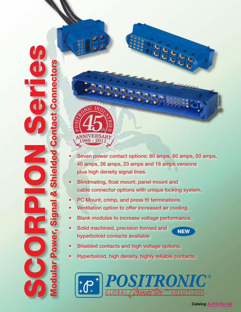
Scorpion
Materials and Finishes:Insulators: , UL 94V-0. Blue color.
Contacts: Precision machined copper alloy with gold upon request. Size 22 PCB straight and right angle (90°) contact also available in precision formed copper alloy and tin over nickel plate at termination end.Mounting Brackets: Brass with tin plate.Push-on Fasteners: Copper alloy with tin plate.Float Mount Bushings: Steel with zinc plate.Mounting clips: Beryllium copper with nickel plate.Jackscrew System: Passivated stainless steel.
Electrical Characteristics:Contact Current Rating (See Page 6 for details of Power Contacts)Standard Conductivity Contacts:Size 8 Contacts: 50 amperes, continuous.Size 12 Contacts: 40 amperes, continuous.Size 16 Contacts: 26 amperes, continuous.Size 18 Contacts: 16 amperes, continuous.Size 22 Contacts: 3 amperes, nominal.Hyperboloid Contacts 0.60mm [0.0236] : 4 amperes, nominal
High Conductivity Contacts:Size 8 Contacts: 80 amperes, continuous.Size 12 Contacts: 60 amperes, continuous.Size 16 Contacts: 40 amperes, continuous.Size 18 Contacts: 23 amperes, continuous.
Initial Contact Resistance (Standard ConductivityContacts) per IEC 512-2, Test 2b:Size 8 Contacts: 0.0006 ohms, maximum.Size 12 Contacts: 0.001 ohms, maximum.Size 16 Contacts: 0.0016 ohms, maximum.Size 18 Contacts: 0.003 ohms, maximum.Size 22 Contacts: 0.005 ohms, maximum.Hyperboloid Contacts 0.60mm [0.0236] : 0.005 ohms, maximum.
Initial Contact Resistance (High ConductivityContacts) per IEC 512-2, Test 2b:Size 8 Contacts: 0.0004 ohms, maximum.Size 12 Contacts: 0.0004 ohms, maximum.Size 16 Contacts: 0.0007 ohms, maximum.Size 18 Contacts: 0.0007 ohms, maximum.
Insulation Resistance per IEC 512-2, Test 3a, Method A: 5 G ohms.
Voltage Proof per IEC 512-2, Test 4a, Method C: For size 8, 12, 16 and 18 contacts, 2200 V r.m.s. typical;for size 22 contacts, 1600 V r.m.s. typical;for Hyperboloid contacts 0.60mm [0.0236], 1200 V r.m.s. typical.
Working Voltage, Clearance and Creepage Distances:
Hot Pluggable [50 Couplings per UL1977, paragraph 15]:Size 12 Contacts: 250 VAC at 25 amperes. Contact sales for details.Size 16 Contacts: Contact sales for availability.
Climatic Characteristic:Working Temperature: -55°C to +125°C.
Mechanical Characteristics:Super Mating System: Integral guide feature allows for misalignment up to 3.80 mm [0.150 inch].
Blind Mating System: Integral guide feature allows for misalignment up to 2.00 mm [0.079 inch].
Locking Latch System: Design of connector body provides locking system for cable to cable, cable to printed board and cable to panel mount applications.
Jackscrew System: Standard threads, 4-40 UNC. Consult sales for other screw sizes
Polarization: Design of connector body provides polarization features.
Removable Contacts: Install contact from rear face of insulator, release from front face of insulator with a contact extraction tool, thereafter extract contact from rear face of insulator. Size 8, Size 12, Size 16, Size 18 and Size 22 female contacts feature “Closed entry” design for highest reliability.
Keying Features: Consult sales for availability.
Removable Contact Retention in Connector Bodyper IEC 512-8, Test 15a: Size 8, Size 12 and Size 16 Contacts: 67N [15 lbs.] minimum.Size 18 Contacts: 45N [10 lbs.] minimum.Size 22 Contacts: 27N [6 lbs.] minimum.
Non Removable Crimp Contact: Insert contact to rear face of insulator. Size 22 female contact has “closed entry” design for highest reliability.
Non Removable Crimp Contact Retention in Connector Bodyper IEC 512-8, Test 15a:Size 22 Contacts: 27N [ 6 lbs.] minimum.
Fixed Contacts: Printed board terminations, both straight and right angle. Size 8, 12, 16, 18 and Hyperboloid 0.60mm [0.0236] female contacts feature “Closed entry” design for highest reliability. Size 22 female contact has “Open Entry” design.
Fixed Contact Retention in Connector Bodyper IEC 512-8, Test 15a:Size 8 Contacts: 67N [15 lbs.] minimum.Size 12 and Size 16 Contacts: 45N [10 lbs.] minimum.Size 18 Contacts: 45N [10 lbs.] minimum.Size 22 Contacts: 27N [ 6 lbs.] minimum.Size 22 Precision Formed Contact: 27N [ 6 lbs.] minimum.Hyperboloid Contacts 0.60mm [0.0236]: 27N [ 6 lbs.] minimum.
Sequential Contact Mating System:Size 8 Contacts: One level. Consult sales for two levels.Size 12 Contacts: Two levels. Consult sales for three levels.Size 16 Contacts: Two levels. Consult sales for three levels.Size 18 Contacts: Two levels. Consult sales for three levels.Size 22 Contacts: One level. Two levels for Printed Board mount connectors.Hyperboloid Contacts 0.60mm [0.0236]: One level.
Printed Board and Panel Mounting Holes:Mounting holes provided in connector body for both printed board and panel mounting. Self-tapping screws or push-on fastener options are available.
Mechanical Operations per IEC 512-5: Size 8, 12, 16 and 18 contacts: 1000 cycles minimum. Size 22 contacts: 500 cycles minimum. Size 22 Precision Formed contact: 250 cycles minimum.Hyperboloid Contacts 0.60mm [0.0236] : Up to 100,000 cycles.
Recognized: UL in process. Consult sales for TÜV.
Technical Characteristics
Positronic Industrieswww.connectpositronic.com
www.positronicasia.com
Information in this catalog is proprietary to Positronic and its subsidiaries. Positronic believes the data contained herein to be reliable. Since the technical information is given free of charge, the user employs such information at his own discretion and risk. Positronic Industries assumes no responsibility for results obtained or damages incurred from use of such information in whole or in part.
Positronic®, Positronic Industries, Inc.®, P+ logo, Positronic Global Connector Solutions®, Connector Excellence® and their logo designs are registered trademarks of Positronic Industries, Inc.PICMG® logo is a registered trademark of the PCI Industrial Computers Manufacturers Group.
15.7mm X 80mm
Blue colored connectors shown in this catalog are a trademark of Positronic Industries, Inc, registered in the US.
A-010 Rev. B4
A-010 Rev. B4
Positronic Industrieswww.connectpositronic.com
www.positronicasia.com
Scorpion Typical Scorpion Modular Connectors
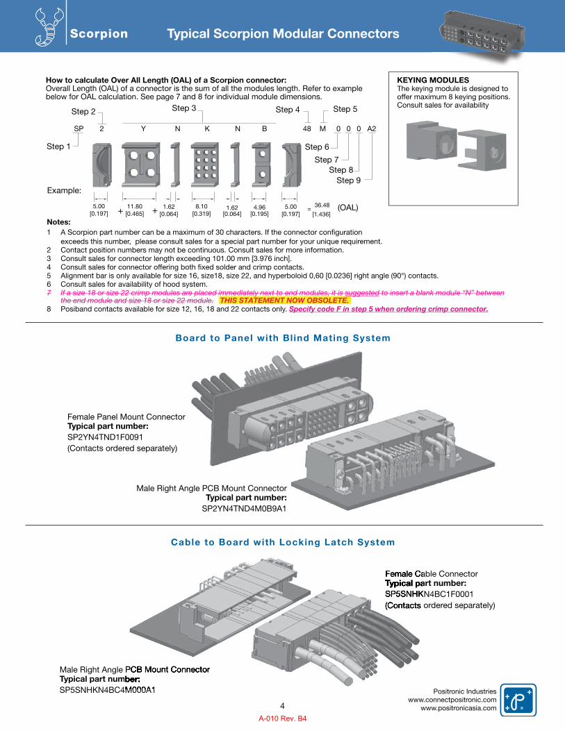
Board to Panel with Bl ind Mating System
Cable to Board with Locking Latch System
Female Panel Mount ConnectorTypical part number: SP2YN4TND1F0091(Contacts ordered separately)
Female Cable ConnectorTypical part number:SP5SNHKN4BC1F0001(Contacts ordered separately)
Male Right Angle PCB Mount ConnectorTypical part number:SP5SNHKN4BC4M000A1
Male Right Angle PCB Mount ConnectorTypical part number:
SP2YN4TND4M0B9A1
Female Cable ConnectorTypical part number:Typical part number:TSP5SNHKN4BC1F0001(Contacts o
Male Right Angle PCB Mount Connectorypical part number:
SP5SNHKN4BC4M000A1
4
SP 2 Y N K N B 48 M 0 0 0 A2
Example:
Step 1
Step 5 Step 3
Step 8Step 9
Step 7
Step 6
Step 2 Step 4
8.10 [0.319]
4.96 [0.195]
1.62 [0.064]
5.00[0.197]
11.80 [0.465]
5.00 [0.197] + + =
36.48
[1.436]
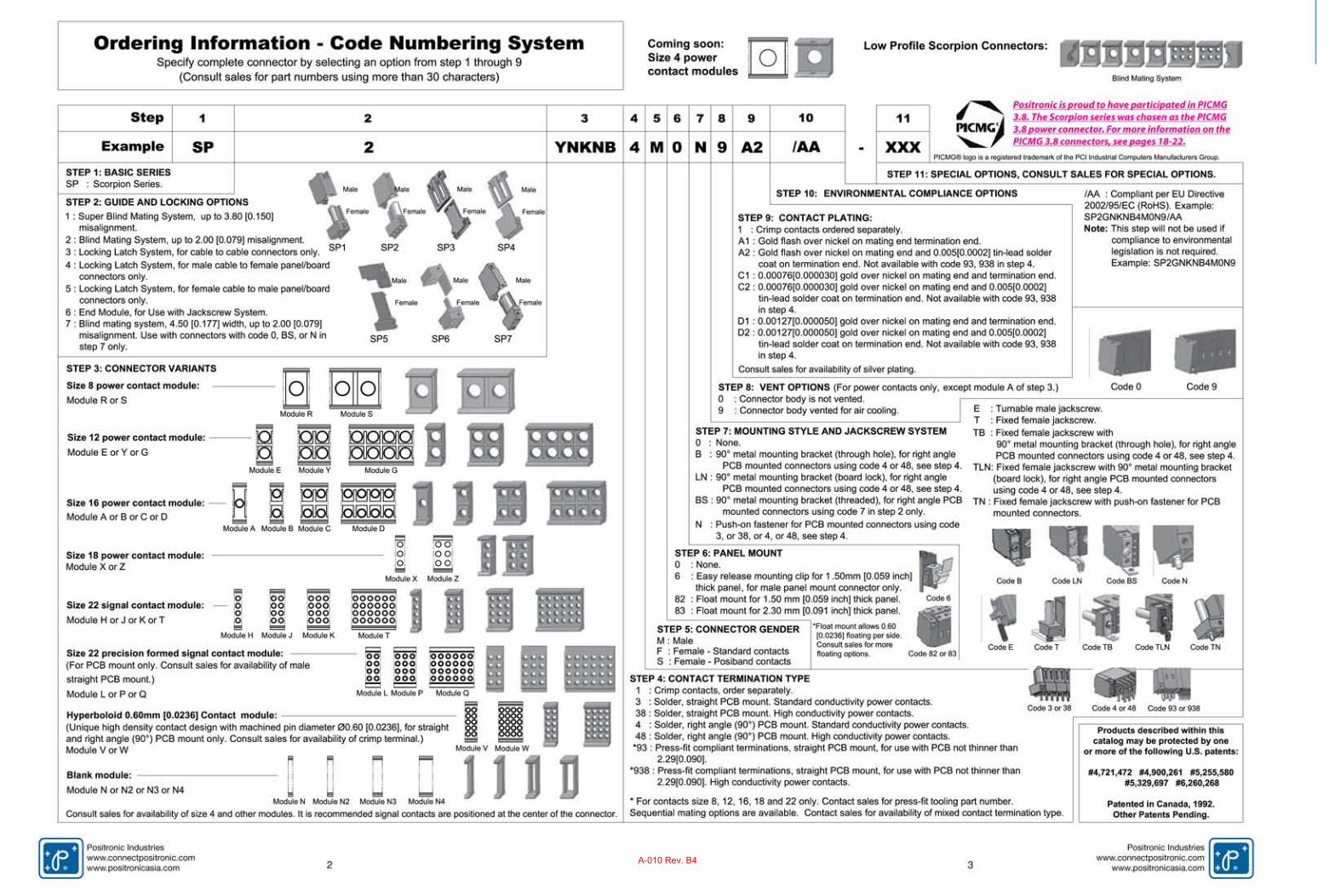
How to calculate Over All Length (OAL) of a Scorpion connector: Overall Length (OAL) of a connector is the sum of all the modules length. Refer to examplebelow for OAL calculation. See page 7 and 8 for individual module dimensions.
KEYING MODULESThe keying module is designed to offer maximum 8 keying positions.Consult sales for availability
(OAL) 1.62[0.064]
Notes: 1 exceeds this number, please consult sales for a special part number for your unique requirement. 2 Contact position numbers may not be continuous. Consult sales for more information. 3 Consult sales for connector length exceeding 101.00 mm [3.976 inch]. 4 5 Alignment bar is only available for size 16, size18, size 22, and hyperboloid 0,60 [0.0236] right angle (90°) contacts. 6 Consult sales for availability of hood system. 7 If a size 18 or size 22 crimp modules are placed immediately next to end modules, it is suggested to insert a blank module “N” between the end module and size 18 or size 22 module. THIS STATEMENT NOW OBSOLETE.8 Posiband contacts available for size 12, 16, 18 and 22 contacts only. Specify code F in step 5 when ordering crimp connector.
A-010 Rev. B4
Positronic Industrieswww.connectpositronic.comwww.positronicasia.com
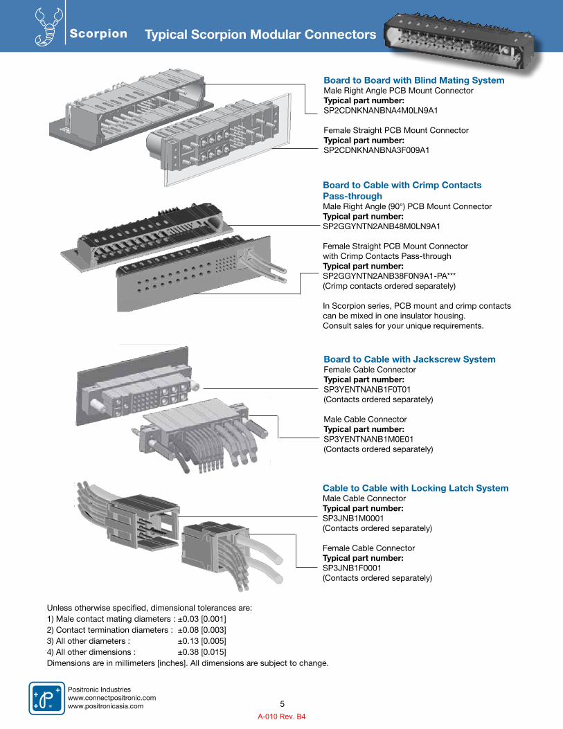
Scorpion Typical Scorpion Modular Connectors
Board to Board with Blind Mating SystemMale Right Angle PCB Mount ConnectorTypical part number:SP2CDNKNANBNA4M0LN9A1
Female Straight PCB Mount ConnectorTypical part number:SP2CDNKNANBNA3F009A1
Board to Cable with Jackscrew SystemFemale Cable ConnectorTypical part number:SP3YENTNANB1F0T01(Contacts ordered separately)
Male Cable ConnectorTypical part number:SP3YENTNANB1M0E01(Contacts ordered separately)
Board to Cable with Crimp Contacts Pass-throughMale Right Angle (90°) PCB Mount ConnectorTypical part number: SP2GGYNTN2ANB48M0LN9A1
Female Straight PCB Mount Connector with Crimp Contacts Pass-throughTypical part number: SP2GGYNTN2ANB38F0N9A1-PA***(Crimp contacts ordered separately)
In Scorpion series, PCB mount and crimp contacts can be mixed in one insulator housing.Consult sales for your unique requirements.
Cable to Cable with Locking Latch SystemMale Cable ConnectorTypical part number:SP3JNB1M0001(Contacts ordered separately)
Female Cable ConnectorTypical part number:SP3JNB1F0001(Contacts ordered separately)
Unless otherwise specified, dimensional tolerances are:1) Male contact mating diameters : ±0.03 [0.001]2) Contact termination diameters : ±0.08 [0.003]3) All other diameters : ±0.13 [0.005]4) All other dimensions : ±0.38 [0.015]Dimensions are in millimeters [inches]. All dimensions are subject to change.
5
A-010 Rev. B4
Positronic Industrieswww.connectpositronic.com
www.positronicasia.com
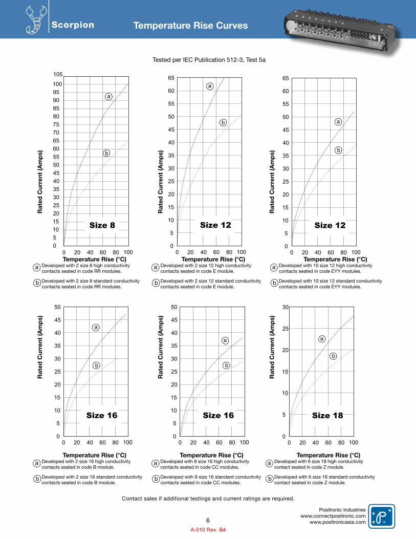
Scorpion Temperature Rise Curves
Tested per IEC Publication 512-3, Test 5a
Temperature Rise (°C)Developed with 2 size 8 high conductivitycontacts seated in code RR modules.
Developed with 2 size 8 standard conductivitycontacts seated in code RR modules.
Temperature Rise (°C)Developed with 2 size 16 high conductivitycontacts seated in code B module.
Developed with 2 size 16 standard conductivity contacts seated in code B module.
Temperature Rise (°C)Developed with 8 size 16 high conductivitycontacts seated in code CC modules.
Developed with 8 size 16 standard conductivitycontacts seated in code CC modules.
Temperature Rise (°C)Developed with 6 size 18 high conductivitycontact seated in code Z module.
Developed with 6 size 18 standard conductivitycontact seated in code Z module.
Temperature Rise (°C)Developed with 2 size 12 high conductivitycontacts seated in code E module.
Developed with 2 size 12 standard conductivitycontacts seated in code E module.
Temperature Rise (°C)Developed with 10 size 12 high conductivitycontacts seated in code EYY modules.
Developed with 10 size 12 standard conductivity contacts seated in code EYY modules.
Rat
ed C
urre
nt (A
mp
s)R
ated
Cur
rent
(Am
ps)
Rat
ed C
urre
nt (A
mp
s)R
ated
Cur
rent
(Am
ps)
Rat
ed C
urre
nt (A
mp
s)R
ated
Cur
rent
(Am
ps)
a
a a a
a a
b
b b b
b b
6
Contact sales if additional testings and current ratings are required.
Size 8
0 20 40 60 80 10005101520253035404550556065707580859095100
105
a
b
Size 12
0 20 40 60 80 1000
5
10
15
20
25
30
35
40
45
50
55
60
65a
b
Size 12
0 20 40 60 80 1000
5
10
15
20
25
30
35
40
45
50
55
60
65
a
b
Size 16
0 20 40 60 80 1000
5
10
15
20
25
30
35
40
45
50
a
b
Size 16
0 20 40 60 80 1000
5
10
15
20
25
30
35
40
45
50
a
b
Size 18
0 20 40 60 80 1000
a
b
5
10
15
20
25
30
A-010 Rev. B4
Positronic Industrieswww.connectpositronic.comwww.positronicasia.com
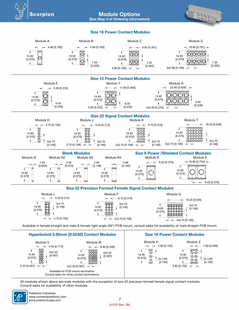
Scorpion Module Options(See Step 3 of Ordering information)
Size 16 Power Contact Modules
Size 12 Power Contact Modules
Size 22 Signal Contact Modules
Blank Modules
Size 18 Power Contact ModulesHyperboloid 0.60mm [0.0236] Contact Modules
All modules shown above are male modules with the exception of size 22 precision formed female signal contact modules.Consult sales for availability of other modules.
Avaliable in female straight and male & female right angle (90°) PCB mount, consult sales for availability of male straight PCB mount.
Available for PCB mount terminationConsult sales for crimp contact terminations
Size 22 Precision Formed Female Signal Contact Modules
Module A
Module E
Module H
Module N
Module L Module P Module Q
Module J
Module N2
Module V
Module K
Module N3
Module XModule W
Module T
Module N4
Module Z
Module Y Module G
Module CModule B Module D
4.96 [0.195]
14.60 [0.575]
4.96 [0.195]
14.60 [0.575]
7.20 [0.283]
9.92 [0.391]
14.60 [0.575]
4.96 [0.195]
7.20 [0.283]
19.84 [0.781]
14.60 [0.575]
3x4.96 [0.195]
7.20 [0.283]
5.90 [0.232]
14.60 [0.575]
6.00 [0.236]
11.80 [0.465]
14.60 [0.575]
5.90 [0.232]6.00
[0.236]
23.60 [0.929]
14.60 [0.575]
3x5.90 [0.232]
6.00 [0.236]
2.70 [0.106]
14.60 [0.575]
3x2.70 [0.106]
5.40 [0.213]
14.60 [0.575]
2.70 [0.106]3x2.70 [0.106]
8.10 [0.319]
14.60 [0.575]
2x2.70 [0.106]3x2.70 [0.106]
16.20 [0.638]
14.60 [0.575]
5x2.70 [0.106]3x2.70 [0.106]
Size 8 Power /Shielded Contact ModulesModule R Module S
9.40 [0.370]
14.60 [0.575]
18.80 [0.740]
14.60 [0.575]
9.40 [0.370]
4.40 [0.173]
14.60 [0.575]
2.20 [0.087]
4x2.20 [0.087]
8.80 [0.346]
14.60 [0.575]
3x2.20 [0.087]
4x2.20 [0.087]
7
5.40 [0.213]
14.60 [0.575]
2.70 [0.106]
3x2.70 [0.106]
8.10 [0.319]
14.60 [0.575]
2x2.70 [0.106]
3x2.70 [0.106]
16.20 [0.638]
14.60 [0.575]
5x2.70 [0.106]
3x2.70 [0.106]
1.62 [0.064]
14.60 [0.575]
14.60 [0.575]
14.60 [0.575]
14.60 [0.575]
2.00 [0.079]
3.46 [0.136]
4.88 [0.192]
3.80 [0.150]
14.60 [0.575] 2x 3.80
[0.150]
7.60 [0.299]
14.60 [0.575]
3.80 [0.150]
2x 3.80 [0.150]
A-010 Rev. B4
Positronic Industrieswww.connectpositronic.com
www.positronicasia.com
Scorpion
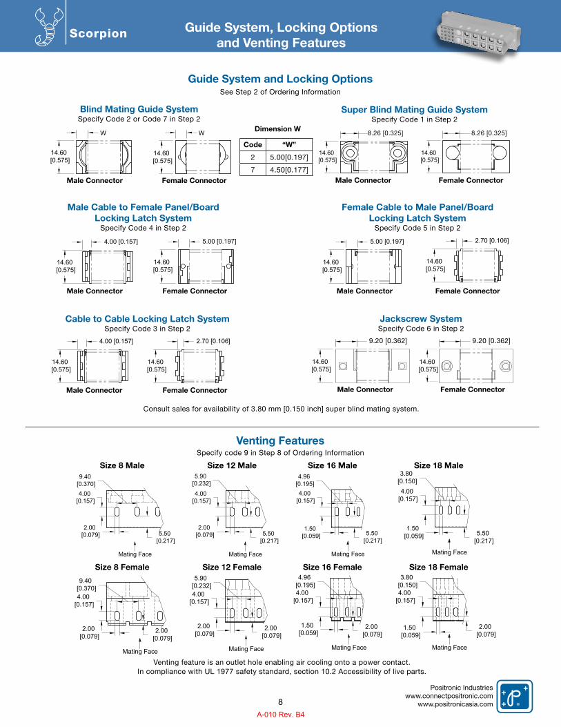
Consult sales for availability of 3.80 mm [0.150 inch] super blind mating system.
Guide System, Locking Optionsand Venting Features
Guide System and Locking OptionsSee Step 2 of Ordering Information
Blind Mating Guide SystemSpecify Code 2 or Code 7 in Step 2
Male Cable to Female Panel/BoardLocking Latch System
Specify Code 4 in Step 2
Female Cable to Male Panel/BoardLocking Latch System
Specify Code 5 in Step 2
Venting FeaturesSpecify code 9 in Step 8 of Ordering Information
Size 8 Male
Male Connector
Male Connector Male Connector
Female Connector
Dimension W
Code “W”
2 5.00[0.197]
7 4.50[0.177]
Female Connector Female Connector
Size 8 Female
Size 12 Male
Size 12 Female
Venting feature is an outlet hole enabling air cooling onto a power contact.In compliance with UL 1977 safety standard, section 10.2 Accessibility of live parts.
Size 18 MaleSize 16 Male
Size 18 FemaleSize 16 Female
14.60 [0.575]
14.60 [0.575]
Cable to Cable Locking Latch SystemSpecify Code 3 in Step 2
Male Connector Female Connector
14.60 [0.575]
4.00 [0.157]
14.60 [0.575]
2.70 [0.106]
14.60 [0.575]
4.00 [0.157]
14.60 [0.575]
5.00 [0.197]
14.60 [0.575]
5.00 [0.197]
14.60 [0.575]
2.70 [0.106]
4.00 [0.157]
2.00 [0.079]
9.40 [0.370]
2.00 [0.079]
Mating Face
4.00 [0.157]
2.00 [0.079]
2.00 [0.079]
5.90 [0.232]
Mating Face
4.00 [0.157]
1.50 [0.059]
2.00 [0.079]
4.96 [0.195]
Mating Face
8
4.00 [0.157]
1.50 [0.059] 5.50
[0.217]
3.80 [0.150]
Mating Face
Mating Face
4.00 [0.157]
1.50 [0.059]
2.00 [0.079]
3.80 [0.150]
Jackscrew SystemSpecify Code 6 in Step 2
Male Connector Female Connector
8.26 [0.325]8.26 [0.325]WW
Super Blind Mating Guide SystemSpecify Code 1 in Step 2
Male Connector Female Connector
14.60 [0.575]
14.60 [0.575]
14.60 [0.575]
9.40 [0.370]
14.60 [0.575]
9.40 [0.370]9.20 [0.362]9.20 [0.362]
4.00 [0.157]
2.00 [0.079] 5.50
[0.217]
9.40 [0.370]
Mating Face
4.00 [0.157]
2.00 [0.079] 5.50
[0.217]
5.90 [0.232]
Mating Face
4.00 [0.157]
1.50 [0.059] 5.50
[0.217]
4.96 [0.195]
Mating Face
A-010 Rev. B4
Positronic Industrieswww.connectpositronic.comwww.positronicasia.com
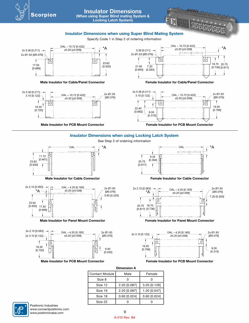
ScorpionInsulator Dimensions
(When using Super Blind mating System & Locking Latch System)
Insulator Dimensions when using Super Blind Mating SystemSpecify Code 1 in Step 2 of ordering information
Insulator Dimensions when using Locking Latch SystemSee Step 2 of ordering information
Dimension A
Contact Module Male Female
Size 8 0 0
Size 12 2.20 [0.087] 3.20 [0.126]
Size 16 2.20 [0.087] 1.20 [0.047]
Size 18 0.60 [0.024] 0.60 [0.024]
Size 22 0 0
9
17.50 [0.689]
23.62 [0.930]
*A2x Ø1.93 [Ø0.076]
OAL 10.72 [0.422] ±0.20 [±0.008]2x 5.36 [0.211]
21.60 [0.850]
2x Ø1.93 [Ø0.076]
*A
20.75 [0.817]
5.36 [0.211]
7.20 [0.283]
18.70 [0.736]
OAL 10.72 [0.422] ±0.20 [±0.008]
Male Insulator for Cable/Panel Connector
Male Insulator for PCB Mount Connector
Male Insulator for Cable Connector
Male Insulator for Panel Mount Connector
Male Insulator for PCB Mount Connector
Female Insulator for Cable/Panel Connector
Female Insulator for PCB Mount Connector
Female Insulator for Cable Connector
Female Insulator for Panel Mount Connector
Female Insulator for PCB Mount Connector
18.30 [0.720]
3.10 [0.122] 2x Ø1.93 [Ø0.076]
2x 5.36 [0.211]OAL 10.72 [0.422]
±0.20 [±0.008]
22.40 [0.882]
19.50 [0.768]
2x Ø1.93 [Ø0.076]
8.00 [0.315]
3.10 [0.122]2x 5.36 [0.211]
OAL 10.72 [0.422]±0.20 [±0.008]
OAL
23.62 [0.930]
11.72 [0.461]
*A
20.75 [0.817]
OAL
9.25 [0.364]
*A
17.50 [0.689]
5.60 [0.220]
23.62 [0.930]
*A2x Ø1.93 [Ø0.076]
2x 2.10 [0.083] OAL 4.20 [0.165] ±0.20 [±0.008]
20.75 [0.817]
18.70 [0.736]
7.20 [0.283]*A
2x Ø1.93 [Ø0.076]
OAL 4.20 [0.165] ±0.20 [±0.008]
2x 2.10 [0.083]
18.30 [0.720] 6.40
[0.252]
2x 3.10 [0.122]2x Ø1.93 [Ø0.076]
OAL 4.20 [0.165] ±0.20 [±0.008]
2x 2.10 [0.083]
19.50 [0.768] 8.00
[0.315]
2x 3.10 [0.122]2x Ø1.93 [Ø0.076]
OAL 4.20 [0.165] ±0.20 [±0.008]
A-010 Rev. B4
Positronic Industrieswww.connectpositronic.com
www.positronicasia.com
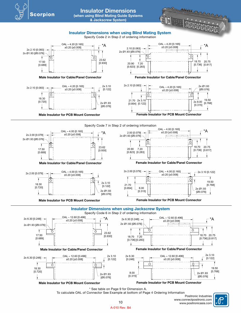
ScorpionInsulator Dimensions
(when using Blind Mating Guide Systems& Jackscrew System)
Insulator Dimensions when using Blind Mating SystemSpecify Code 2 in Step 2 of ordering information
Specify Code 7 in Step 2 of ordering information
Insulator Dimensions when using Jackscrew SystemSpecify Code 6 in Step 2 of ordering information
Male Insulator for Cable/Panel Connector
Male Insulator for PCB Mount Connector
Male Insulator for Cable/Panel Connector
Male Insulator for PCB Mount Connector
Male Insulator for PCB Mount Connector
Male Insulator for Cable/Panel Connector
Female Insulator for Cable/Panel Connector
Female Insulator for PCB Mount Connector
Female Insulator for Cable/Panel Connector
Female Insulator for PCB Mount Connector
Female Insulator for PCB Mount Connector
Female Insulator for Cable/Panel Connector
To calculate OAL of Connector See Example at bottom of Page 4 Ordering Information* See table on Page 9 for Dimension A.
10
17.50 [0.689]
23.62 [0.930]
*A
2x Ø1.93 [Ø0.076]
OAL 4.20 [0.165] ±0.20 [±0.008]
2x 2.10 [0.083]
20.90 [0.823]
2x Ø1.93 [Ø0.076]
*A
20.75 [0.817]
2.10 [0.083]
7.20 [0.283]
18.70 [0.736]
OAL 4.20 [0.165] ±0.20 [±0.008]
18.30 [0.720] 2x Ø1.93
[Ø0.076]
OAL 4.20 [0.165]±0.20 [±0.008]2x 2.10 [0.083] 2x 3.10
[0.122]
21.70 [0.854]
19.50 [0.768]
2x Ø1.93 [Ø0.076]
2x 3.10 [0.122]
2x 2.10 [0.083] OAL 4.20 [0.165]±0.20 [±0.008]
2x 8.00 [0.315]
17.50 [0.689]
23.62 [0.930]
*AOAL 4.00 [0.165] ±0.20 [±0.008]2x 2.00 [0.079]
2x Ø1.93 [Ø0.076]
20.90 [0.823]
*A
20.75 [0.817]
2.00 [0.079]
7.20 [0.283]
18.70 [0.736]
OAL 4.00 [0.165] ±0.20 [±0.008]
2x Ø1.93 [Ø0.076]
18.30 [0.720]
OAL 4.00 [0.165]±0.20 [±0.008]2x 2.00 [0.079]
2x Ø1.93 [Ø0.076]
2x 3.10 [0.122] 21.70
[0.854]
19.50 [0.768]
8.00 [0.315]
2x 2.00 [0.079] OAL 4.00 [0.165]±0.20 [±0.008]
2x Ø1.93 [Ø0.076]
2x 3.10 [0.122]
17.50 [0.689]
23.62 [0.930]
*A2x Ø1.93 [Ø0.076]
OAL 12.60 [0.496] ±0.20 [±0.008]2x 6.30 [0.248] 2x 6.30 [0.248]
18.70 [0.736]
2x Ø1.93 [Ø0.076]*A
20.75 [0.817]7.20
[0.283]
18.70 [0.736]
OAL 12.60 [0.496] ±0.20 [±0.008]
18.30 [0.720]
2x Ø1.93 [Ø0.076]
OAL 12.60 [0.496]±0.20 [±0.008]2x 6.30 [0.248] 2x 3.10
[0.122]
19.50 [0.768]
2x Ø1.93 [Ø0.076]
8.00 [0.315]
2x 6.30 [0.248]
OAL 12.60 [0.496]±0.20 [±0.008]
2x 3.10 [0.122]
A-010 Rev. B4
Positronic Industrieswww.connectpositronic.comwww.positronicasia.com
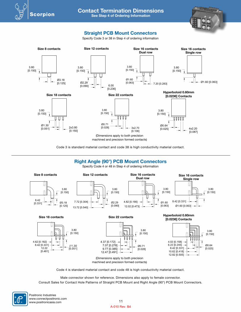
ScorpionContact Termination Dimensions
See Step 4 of Ordering Information
Size 22 contactsSize 18 contacts
(Dimensions apply to both precision machined and precision formed contacts)
(Dimensions apply to both precision machined and precision formed contacts)
Size 22 contacts
Size 12 contacts
Size 12 contacts
Size 8 contacts
Size 8 contacts
Hyperboloid 0.60mm[0.0236] Contacts
Hyperboloid 0.60mm[0.0236] Contacts
Size 18 contacts
Size 16 contacts Dual row
Size 16 contacts Dual row
Size 16 contacts Single row
Size 16 contacts Single row
Straight PCB Mount ConnectorsSpecify Code 3 or 38 in Step 4 of ordering information
Right Angle (90°) PCB Mount ConnectorsSpecify Code 4 or 48 in Step 4 of ordering information
Male connector shown for reference. Dimensions also apply to female connector.
Consult Sales for Contact Hole Patterns of Straight PCB Mount and Right Angle (90°) PCB Mount Connectors.
Code 3 is standard material contact and code 38 is high conductivity material contact.
Code 4 is standard material contact and code 48 is high conductivity material contact.
Ø1.60 [0.063]
3.80 [0.150]
11
3.80 [0.150]
Ø1.30 [0.051] 2x3.80
[0.150]
Ø0.64 [0.025] 4x2.20
[0.087]
3.80 [0.150]
3.80 [0.150]
Ø3.18 [0.125] Ø2.29
[0.090]
3.80 [0.150]
6.00 [0.236]
Ø1.60 [0.063]
3.80 [0.150]
7.20 [0.283]
Ø0.71 [0.028]
3.80 [0.150]
3x2.70[0.106]
8.42 [0.331]
3.80 [0.150]
Ø3.18 [0.125]
7.72 [0.304]
13.72 [0.540]
3.80 [0.150]
Ø2.29 [0.090]
4.82 [0.190] Ø1.60 [0.063]
3.80 [0.150]
12.02 [0.473]
8.42 [0.331]
3.80 [0.150]
Ø1.60 [0.063]
4.62 [0.182]
12.22 [0.481]
3.80 [0.150]
8.42 [0.331]
12.47 [0.491]9.77 [0.385]7.07 [0.278]
4.37 [0.172]
3.80 [0.150]
Ø0.71 [0.028]
3.80 [0.150]
4.02 [0.158]6.22 [0.245]
8.42 [0.331]10.62 [0.418]12.82 [0.505]
Ø0.64 [0.025]
∅1.30[0.051]
A-010 Rev. B4
Positronic Industrieswww.connectpositronic.comwww.positronicasia.com
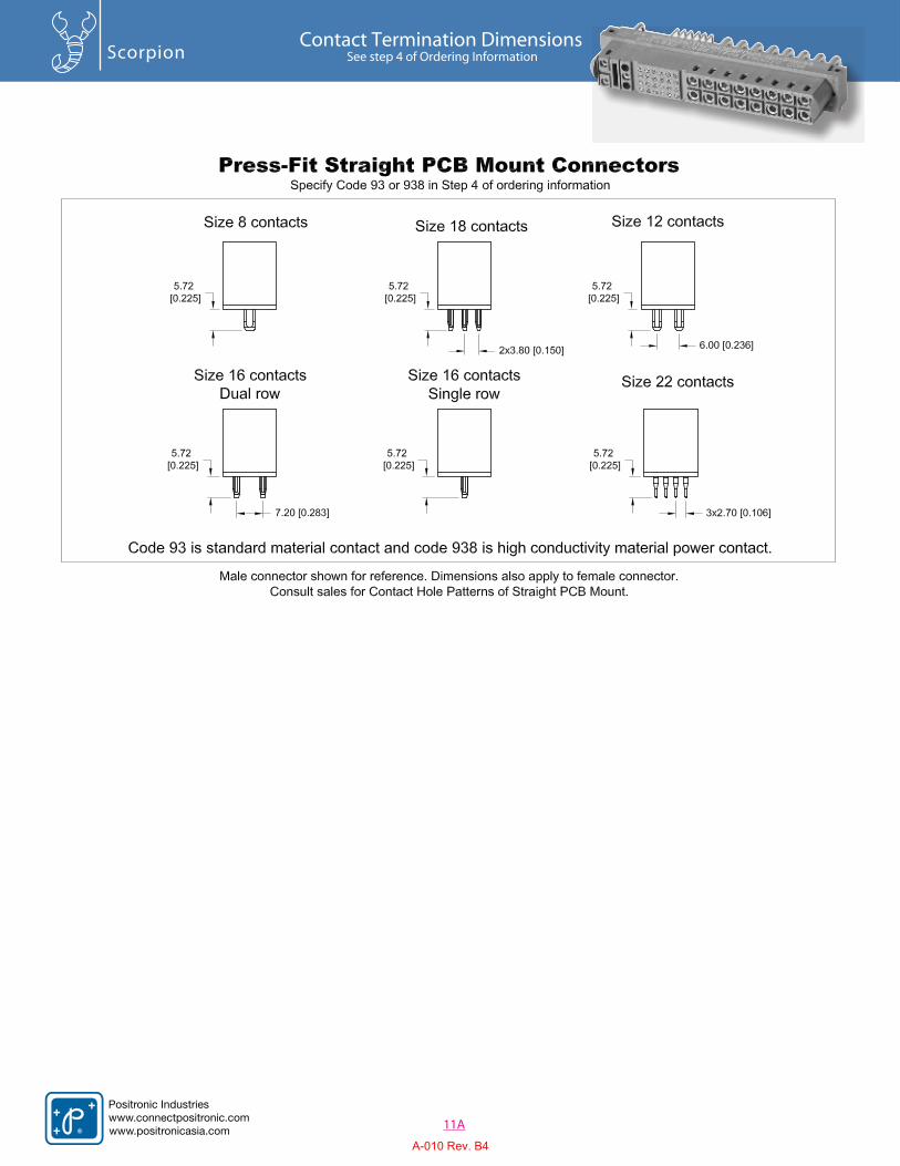
ScorpionContact Termination Dimensions
See step 4 of Ordering Information
11A
Positronic Industrieswww.connectpositronic.comwww.positronicasia.com
A-010 Rev. B4
Positronic Industrieswww.connectpositronic.com
www.positronicasia.com
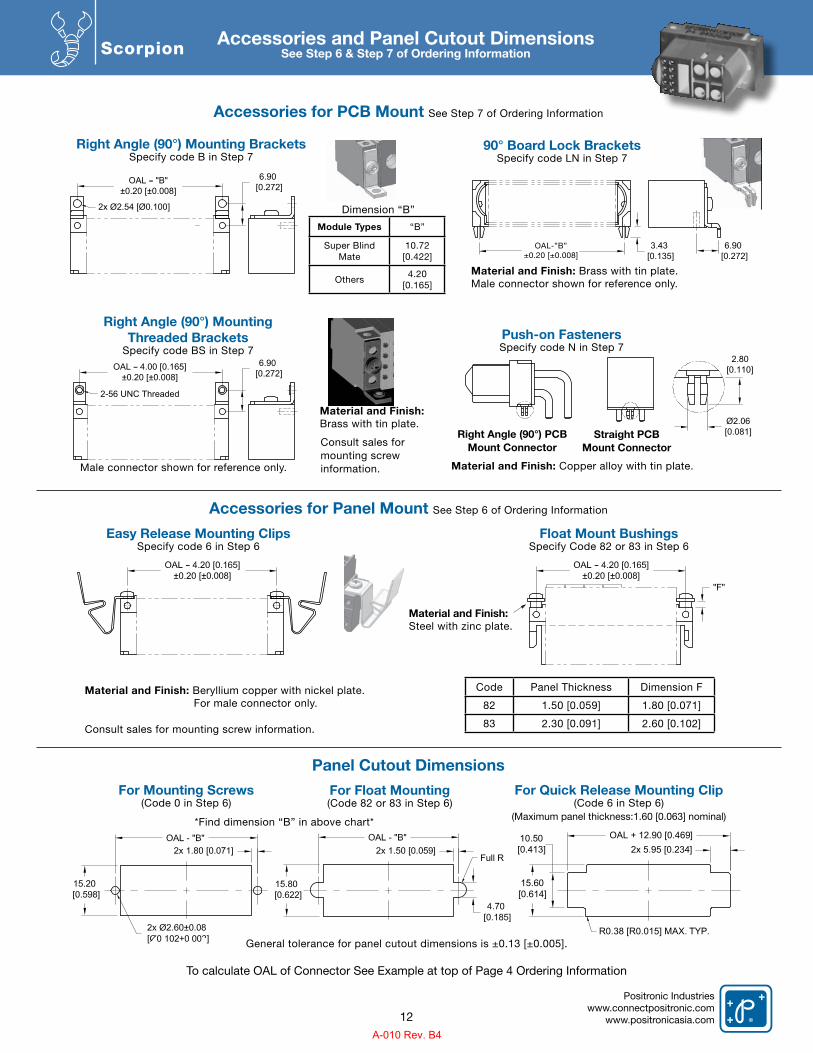
Scorpion Accessories and Panel Cutout DimensionsSee Step 6 & Step 7 of Ordering Information
Right Angle (90°) Mounting BracketsSpecify code B in Step 7
Right Angle (90°) MountingThreaded Brackets
Specify code BS in Step 7
Easy Release Mounting ClipsSpecify code 6 in Step 6
For Mounting Screws(Code 0 in Step 6)
For Float Mounting(Code 82 or 83 in Step 6)
For Quick Release Mounting Clip(Code 6 in Step 6)
(Maximum panel thickness:1.60 [0.063] nominal)
90° Board Lock BracketsSpecify code LN in Step 7
Float Mount BushingsSpecify Code 82 or 83 in Step 6
Material and Finish: Brass with tin plate.Male connector shown for reference only.
Material and Finish: Copper alloy with tin plate.
Consult sales for mounting screw information.
Dimension “B”
Male connector shown for reference only.
Material and Finish: Steel with zinc plate.
Material and Finish: Brass with tin plate.
Material and Finish: Beryllium copper with nickel plate. For male connector only.
Consult sales for mounting screw information.
Accessories for PCB Mount See Step 7 of Ordering Information
Accessories for Panel Mount See Step 6 of Ordering Information
Panel Cutout Dimensions
General tolerance for panel cutout dimensions is ±0.13 [±0.005].
*Find dimension “B” in above chart*
To calculate OAL of Connector See Example at top of Page 4 Ordering Information
Push-on FastenersSpecify code N in Step 7
Right Angle (90°) PCB Mount Connector
Straight PCBMount Connector
Code Panel Thickness Dimension F
82 1.50 [0.059] 1.80 [0.071]
83 2.30 [0.091] 2.60 [0.102]
15.60[0.614]
10.50[0.413]
OAL + 12.90 [0.469]
R0.38 [R0.015] MAX. TYP.
2x 5.95 [0.234]
12
2.80[0.110]
Ø2.06[0.081]
3.43 [0.135]
6.90 [0.272]
2x Ø2.54 [Ø0.100]
6.90 [0.272]
OAL "B"±0.20 [±0.008]
2-56 UNC Threaded
6.90 [0.272]
OAL 4.00 [0.165]±0.20 [±0.008]
Module Types “B”
Super Blind Mate
10.72[0.422]
Others4.20
[0.165]
OAL-”B”±0.20 [±0.008]
A-010 Rev. B4
Positronic Industrieswww.connectpositronic.comwww.positronicasia.com
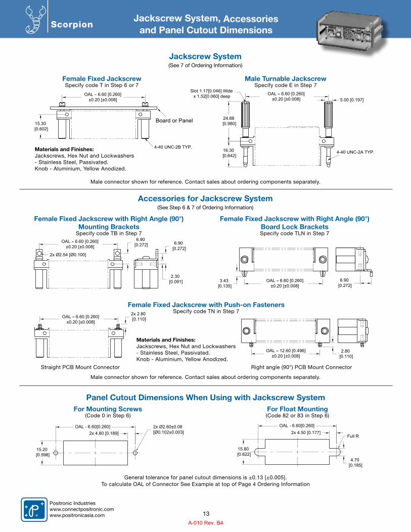
Scorpion
Materials and Finishes: Jackscrews, Hex Nut and Lockwashers- Stainless Steel, Passivated.Knob - Aluminium, Yellow Anodized.
Materials and Finishes: Jackscrews, Hex Nut and Lockwashers- Stainless Steel, Passivated.Knob - Aluminium, Yellow Anodized.
Jackscrew System, Accessoriesand Panel Cutout Dimensions
Jackscrew System (See 7 of Ordering Information)
Accessories for Jackscrew System (See Step 6 & 7 of Ordering Information)
Female Fixed JackscrewSpecify code T in Step 6 or 7
Female Fixed Jackscrew with Right Angle (90°) Mounting Brackets
Specify code TB in Step 7
Female Fixed Jackscrew with Right Angle (90°) Board Lock BracketsSpecify code TLN in Step 7
Female Fixed Jackscrew with Push-on FastenersSpecify code TN in Step 7
Panel Cutout Dimensions When Using with Jackscrew System
Male Turnable JackscrewSpecify code E in Step 7
For Mounting Screws(Code 0 in Step 6)
For Float Mounting(Code 82 or 83 in Step 6)
Straight PCB Mount Connector Right angle (90°) PCB Mount Connector
13
Board or Panel15.30 [0.602]
OAL 6.60 [0.260]±0.20 [±0.008]
4-40 UNC-2B TYP.16.30
[0.642]
OAL 6.60 [0.260]±0.20 [±0.008]
24.88 [0.980]
5.00 [0.197]
Slot 1.17[0.046] Widex 1.52[0.060] deep
4-40 UNC-2A TYP.
2x Ø2.54 [Ø0.100]
6.90 [0.272] 6.90
[0.272]OAL 6.60 [0.260]
±0.20 [±0.008]
2.30 [0.091] 6.90
[0.272]3.43
[0.135]OAL 6.60 [0.260]
±0.20 [±0.008]
2x 2.80 [0.110]OAL 6.60 [0.260]
±0.20 [±0.008]
2.80 [0.110]
OAL 12.60 [0.496]±0.20 [±0.008]
15.20 [0.598]
2x Ø2.60±0.08 [Ø0.102±0.003]
OAL - 6.60[0.260]2x 4.80 [0.189]
15.80 [0.622]
Full R
4.70 [0.185]
2x 4.50 [0.177]OAL - 6.60[0.260]
General tolerance for panel cutout dimensions is ±0.13 [±0.005].To calculate OAL of Connector See Example at top of Page 4 Ordering Information
Male connector shown for reference. Contact sales about ordering components separately.
Male connector shown for reference. Contact sales about ordering components separately.
A-010 Rev. B4
Positronic Industrieswww.connectpositronic.com
www.positronicasia.com
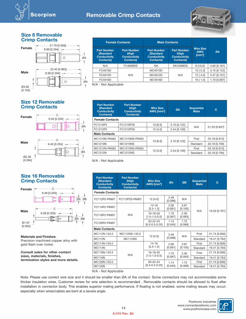
Scorpion Removable Crimp Contacts
Part Number (Standard
Conductivity Contacts)
Part Number(High
ConductivityContacts)
Wire Size AWG [mm²] ØA ØB Sequential
Mate C
Female Contacts
FC112P2-PA907 FC112P2S-PA907 12 [4.0] 2.49 [0.098] N/A
N/A 19.33 [0.761]FC114P2-PA907
N/A
14-16 [2.5-1.5]
2.06 [0.081]
2.67 [0.105]
FC116P2-PA907 16-18-20 [1.5-1.0-0.5]
1.70 [0.067]
2.36 [0.093]
FC120P2-PA907 20-22-24 [0.5-0.3-0.25]
1.14 [0.045]
1.73 [0.068]
Male Contacts
MC112N-133.5 MC112NS-133.512 [4.0] 2.49
[0.098] N/AFirst 21.74 [0.856]
MC112N MC112NS Standard 19.41 [0.764]
MC114N-133.5
N/A
14-16 [2.5-1.5]
2.06 [0.081]
2.67 [0.105]
First 21.74 [0.856]
MC114N Standard 19.41 [0.764]
MC116N-133.5 16-18-20 [1.5-1.0-0.5]
1.70 [0.067]
2.36 [0.093]
First 21.74 [0.856]
MC116N Standard 19.41 [0.764]
MC120N-133.5 20-22-24 [0.5-0.3-0.25]
1.14 [0.045]
1.73 [0.068]
First 21.74 [0.856]
MC120N Standard 19.41 [0.764]
Female
Male
Size 16 RemovableCrimp Contacts
ØBØA
6.48 [0.255]C
Ø1.57 [0.062]
Part Number (Standard
Conductivity Contacts)
Part Number(High
ConductivityContacts)
Wire Size AWG [mm²] ØA Sequential
Mate C
Female Contacts
FC1210P2 FC1210P2S 10 [6.0] 3.10 [0.122]N/A 21.25 [0.837]
FC1212P2 FC1212P2S 12 [4.0] 2.54 [0.100]
Male Contacts
MC1210N-PA563 MC1210NS-PA56310 [6.0] 3.10 [0.122]
First 23.18 [0.912]
MC1210N MC1210NS Standard 20.18 [0.794]
MC1212N-PA563 MC1212NS-PA56312 [4.0] 2.54 [0.100]
First 23.18 [0.912]
MC1212N MC1212NS Standard 20.18 [0.794]
Female
Male
Size 12 RemovableCrimp Contacts
ØA
6.45 [0.254]C
Ø2.38 [0.094]
Female Contacts Male Contacts
Wire Size AWG[mm²]
ØAPart Number (Standard
Conductivity Contacts)
Part Number(High
ConductivityContacts)
Part Number (Standard
Conductivity Contacts)
Part Number(High
ConductivityContacts)
N/A FC4008DS NA MC4008DS 8 [10.0] 4.60 [0.181]
FC4010D
N/A
MC4010D
N/A
10 [ 5.3] 3.10 [0.122]
FC4012D MC4012D 12 [ 4.0] 2.57 [0.101]
FC4016D MC4016D 16 [ 1.5] 1.70 [0.067]
Female
Male
Size 8 RemovableCrimp Contacts
ØA
8.99 [0.354]21.79 [0.858]
ØA
8.99 [0.354]
Ø3.60 [0.142]
22.40 [0.882]
N/A - Not Applicable
N/A - Not Applicable
N/A - Not Applicable
Materials and Finishes: Precision machined copper alloy withgold �ash over nickel.
Consult sales for other contactsizes, materials, finishes,termination styles and more details.
14
Note: Please use correct wire size and it should be smaller than ØA of the contact. Some connectors may not accommodate some
especially when wires/cables are bent at a severe angle.
ØA
6.45 [0.254]C
C6.48 [0.255]
ØBØA
A-010 Rev. B4
Positronic Industrieswww.connectpositronic.comwww.positronicasia.com
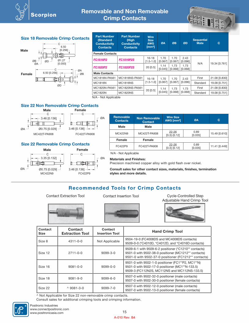
ScorpionRemovable and Non Removable
Crimp Contacts
Size 22 Non Removable Crimp Contacts
Size 18 Removable Crimp Contacts
Recommended Tools for Crimp Contacts
Size 22 Removable Crimp Contacts
Removable Contacts
Non RemovableContact
Wire Size AWG [mm²] ØA C
Male Male
MC422N9 MC422T-PA908 22-26[0.3]-[0.12]
0.89 [0.035] 15.49 [0.610]
Female Female
FC422P9 FC422T-PA908 22-26[0.3]-[0.12]
0.89 [0.035] 11.41 [0.449]
Part Number (Standard
Conductivity Contacts
Part Number (High
Conductivity Contacts
Wire Size AWG [mm²]
ØA ØB ØDSequential
Mate C
Female Contacts
FC1816P2 FC1816P2S 16-18 [1.5-1.0]
1.70[0.067]
1.70[0.067]
2.43[0.096]
N/A 19.34 [0.761]FC1820P2 FC1820P2S 20 [0.5] 1.14
[0.045]1.73
[0.068]1.73
[0.068]
Male Contacts
MC1816N-PA561 MC1816NS-PA561 16-18 [1.5-1.0]
1.70[0.067]
1.70[0.067]
2.43[0.096]
First 21.08 [0.830]
MC1816N MC1816NS Standard 19.08 [0.751]
MC1820N-PA561 MC1820NS-PA56120 [0.5] 1.14
[0.045]1.73
[0.068]1.73
[0.068]First 21.08 [0.830]
MC1820N MC1820NS Standard 19.08 [0.751]
Female
Female
Female
Male
Male
Male
Materials and Finishes: Precision machined copper alloy with gold �ash over nickel.
Contact Extraction Tool Contact Insertion Tool Cycle-Controlled StepAdjustable Hand Crimp Tool
Contact Size
Contact Extraction Tool
Contact Insertion Tool Hand Crimp Tool
Size 8 4311-0-0 Not Applicable9504-19-0 (FC4008DS and MC4008DS contacts)9509-0-0 (*C4010D, *C4012D, and *C4016D contacts)
Size 12 2711-0-0 9099-3-09509-6-1 with 9509-6-2 positioner (*C1210** contacts)9501-0 with 9502-38-0 positioner (MC1212** contacts)9501-0 with 9502-37-0 positioner (FC1212** contacts)
Size 16 9081-0-0 9099-0-09501-0 with 9502-1-0 positioner (FC1**P2, MC1**N)9501-0 with 9502-17-0 positioner (MC1**N-133.5)9509-3 (FC112N2S, MC112NS and MC112NS-133.5)
Size 18 9081-9-0 9099-6-09507-0 with 9502-32-0 positioner (male contacts)9507-0 with 9502-30-0 positioner (female contacts)
Size 22 ^ 9081-3-0 9099-7-09507-0 with 9502-12-0 positioner (male contacts)9507-0 with 9502-13-0 positioner (female contacts)
^ Not Applicable for Size 22 non-removable crimp contacts.Consult sales for additional crimping tools and crimping information.
MC422N9
MC422T-PA908
FC422P9
FC422T-PA908
15
N/A - Not Applicable
N/A - Not Applicable
Consult sales for other contact sizes, materials, finishes, termination styles and more details.
C6.50
[0.256]
Ø1.27 [0.050]
ØDØBØA
C6.50 [0.256]
ØD
ØBØA
Ø0.75 [0.029]ØA
C3.46 [0.136]
C
3.46 [0.136]
ØA
ØA Ø0.75 [0.029]
C3.35 [0.132]
C
3.46 [0.136]
ØA
A-010 Rev. B4
2 3
Positronic Industrieswww.connectpositronic.comwww.positronicasia.com
Positronic Industrieswww.connectpositronic.com
www.positronicasia.com
Positronic Industrieswww.connectpositronic.com
www.positronicasia.com
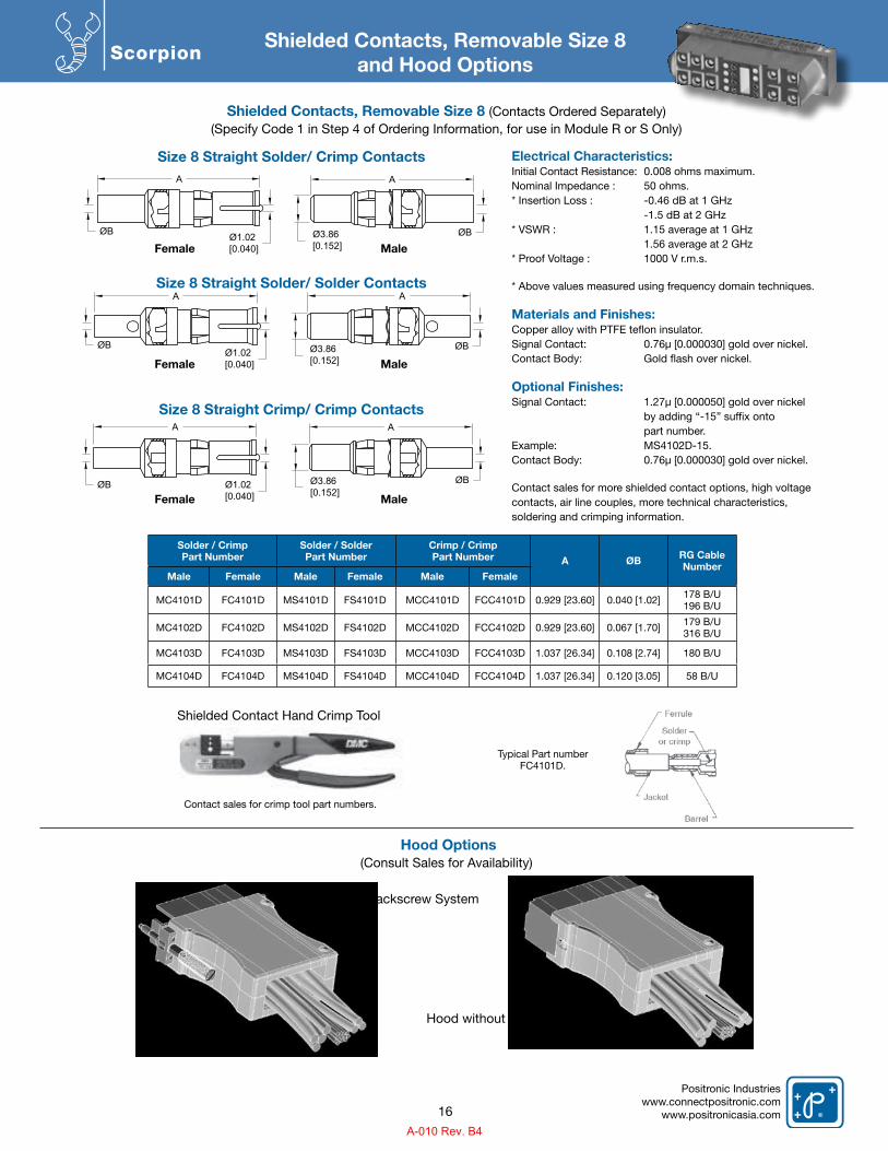
ScorpionShielded Contacts, Removable Size 8
and Hood Options
Size 8 Straight Solder/ Crimp Contacts
Size 8 Straight Solder/ Solder Contacts
Size 8 Straight Crimp/ Crimp Contacts
Female
Female
Female
Male
Male
Male
Shielded Contact Hand Crimp Tool
Contact sales for crimp tool part numbers.
Typical Part numberFC4101D.
A
Ø1.02 [0.040]
ØB ØB
A
Ø3.86 [0.152]
A
Ø3.86 [0.152]
ØB
A
Ø1.02 [0.040]
ØB
A
Ø3.86 [0.152]
ØBØ1.02 [0.040]
A
ØB
Solder / CrimpPart Number
Solder / SolderPart Number
Crimp / CrimpPart Number A ØB RG Cable
NumberMale Female Male Female Male Female
MC4101D FC4101D MS4101D FS4101D MCC4101D FCC4101D 0.929 [23.60] 0.040 [1.02] 178 B/U196 B/U
MC4102D FC4102D MS4102D FS4102D MCC4102D FCC4102D 0.929 [23.60] 0.067 [1.70] 179 B/U316 B/U
MC4103D FC4103D MS4103D FS4103D MCC4103D FCC4103D 1.037 [26.34] 0.108 [2.74] 180 B/U
MC4104D FC4104D MS4104D FS4104D MCC4104D FCC4104D 1.037 [26.34] 0.120 [3.05] 58 B/U
Electrical Characteristics:Initial Contact Resistance: 0.008 ohms maximum.Nominal Impedance : 50 ohms.* Insertion Loss : -0.46 dB at 1 GHz -1.5 dB at 2 GHz* VSWR : 1.15 average at 1 GHz 1.56 average at 2 GHz* Proof Voltage : 1000 V r.m.s.
* Above values measured using frequency domain techniques.
Materials and Finishes:Copper alloy with PTFE teflon insulator.Signal Contact: 0.76μ [0.000030] gold over nickel.Contact Body: Gold flash over nickel.
Optional Finishes:Signal Contact: 1.27μ [0.000050] gold over nickel by adding “-15” suffix onto part number.Example: MS4102D-15.Contact Body: 0.76μ [0.000030] gold over nickel.
Contact sales for more shielded contact options, high voltage contacts, air line couples, more technical characteristics, soldering and crimping information.
Shielded Contacts, Removable Size 8 (Contacts Ordered Separately)(Specify Code 1 in Step 4 of Ordering Information, for use in Module R or S Only)
Hood Options(Consult Sales for Availability)
16
Hood with Jackscrew System
Hood without Jackscrew System
A-010 Rev. B4
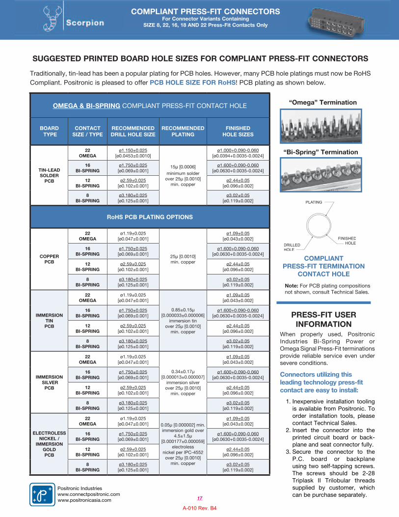
SUGGESTED PRINTED BOARD HOLE SIZES FOR COMPLIANT PRESS-FIT CONNECTORS
Traditionally, tin-lead has been a popular plating for PCB holes. However, many PCB hole platings must now be RoHS Compliant. Positronic is pleased to offer PCB HOLE SIZE FOR RoHS! PCB plating as shown below.
Note: For PCB plating compositions not shown, consult Technical Sales.
OMEGA & BI-SPRING COMPLIANT PRESS-FIT CONTACT HOLE
BOARD TYPE
CONTACTSIZE / TYPE
RECOMMENDED DRILL HOLE SIZE
RECOMMENDED PLATING
FINISHEDHOLE SIZES
TIN-LEAD SOLDER
PCB
22OMEGA
ø1.150±0.025[ø0.0453±0.0010]
15µ [0.0006] minimum solder
over 25µ [0.0010] min. copper
ø1.000+0.090-0.060 [ø0.0394+0.0035-0.0024]
16BI-SPRING
ø1.750±0.025[ø0.069±0.001]
ø1.600+0.090-0.060 [ø0.0630+0.0035-0.0024]
12BI-SPRING
ø2.59±0.025[ø0.102±0.001]
ø2.44±0.05 [ø0.096±0.002]
8BI-SPRING
ø3.180±0.025[ø0.125±0.001]
ø3.02±0.05[ø0.119±0.002]
RoHS PCB PLATING OPTIONS
COPPER PCB
22OMEGA
ø1.19±0.025 [ø0.047±0.001]
25µ [0.0010] min. copper
ø1.09±0.05[ø0.043±0.002]
16BI-SPRING
ø1.750±0.025[ø0.069±0.001]
ø1.600+0.090-0.060 [ø0.0630+0.0035-0.0024]
12BI-SPRING
ø2.59±0.025[ø0.102±0.001]
ø2.44±0.05 [ø0.096±0.002]
8BI-SPRING
ø3.180±0.025[ø0.125±0.001]
ø3.02±0.05[ø0.119±0.002]
IMMERSION TIN PCB
22OMEGA
ø1.19±0.025 [ø0.047±0.001]
0.85±0.15µ[0.000033±0.000006]
immersion tin over 25µ [0.0010]
min. copper
ø1.09±0.05[ø0.043±0.002]
16BI-SPRING
ø1.750±0.025[ø0.069±0.001]
ø1.600+0.090-0.060 [ø0.0630+0.0035-0.0024]
12BI-SPRING
ø2.59±0.025[ø0.102±0.001]
ø2.44±0.05 [ø0.096±0.002]
8BI-SPRING
ø3.180±0.025[ø0.125±0.001]
ø3.02±0.05[ø0.119±0.002]
IMMERSION SILVER
PCB
22OMEGA
ø1.19±0.025 [ø0.047±0.001]
0.34±0.17µ[0.000013±0.000007]
immersion silver over 25µ [0.0010]
min. copper
ø1.09±0.05[ø0.043±0.002]
16BI-SPRING
ø1.750±0.025[ø0.069±0.001]
ø1.600+0.090-0.060 [ø0.0630+0.0035-0.0024]
12BI-SPRING
ø2.59±0.025[ø0.102±0.001]
ø2.44±0.05 [ø0.096±0.002]
8BI-SPRING
ø3.180±0.025[ø0.125±0.001]
ø3.02±0.05[ø0.119±0.002]
ELECTROLESSNICKEL /
IMMERSIONGOLDPCB
22OMEGA
ø1.19±0.025 [ø0.047±0.001] 0.05µ [0.000002] min.
immersion gold over 4.5±1.5µ
[0.000177±0.000059] electroless
nickel per IPC-4552 over 25µ [0.0010]
min. copper
ø1.09±0.05[ø0.043±0.002]
16BI-SPRING
ø1.750±0.025[ø0.069±0.001]
ø1.600+0.090-0.060 [ø0.0630+0.0035-0.0024]
12BI-SPRING
ø2.59±0.025[ø0.102±0.001]
ø2.44±0.05 [ø0.096±0.002]
8BI-SPRING
ø3.180±0.025[ø0.125±0.001]
ø3.02±0.05[ø0.119±0.002]
“Bi-Spring” Termination
“Omega” Termination
When properly used, Positronic Industries Bi-Spring Power or Omega Signal Press-Fit terminations provide reliable service even under severe conditions.
Connectors utilizing this leading technology press-fit contact are easy to install:
1. Inexpensive installation tooling is available from Positronic. To order installation tools, please contact Technical Sales.
2. Insert the connector into the printed circuit board or back-plane and seat connector fully.
3. Secure the connector to the P.C. board or backplane using two self-tapping screws. The screws should be 2-28 Triplask II Trilobular threads supplied by customer, which can be purchase separately.
PRESS-FIT USER INFORMATION
COMPLIANT PRESS-FIT TERMINATION
CONTACT HOLE
COMPLIANT PRESS-FIT CONNECTORSFor Connector Variants Containing
SIZE 8, 22, 16, 18 AND 22 Press-Fit Contacts Only
17
Positronic Industrieswww.connectpositronic.comwww.positronicasia.com
A-010 Rev. B4
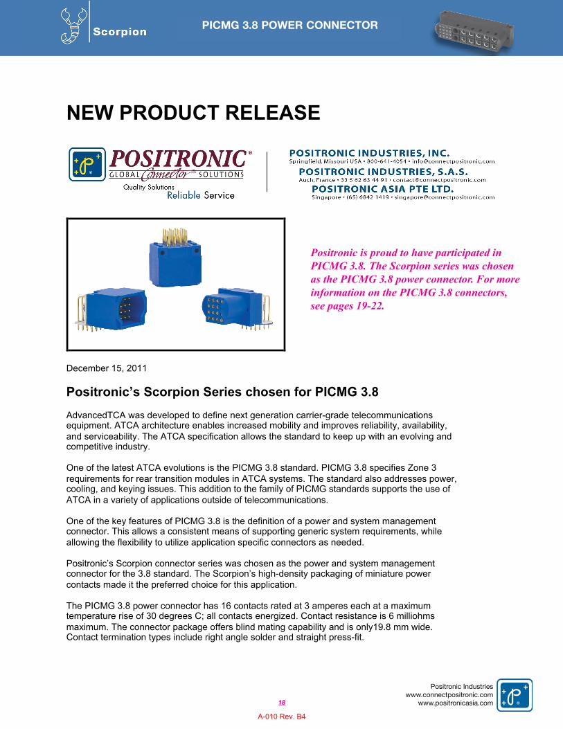
NEW PRODUCT RELEASE
December 15, 2011
Positronic’s Scorpion Series chosen for PICMG 3.8
AdvancedTCA was developed to define next generation carrier-grade telecommunications equipment. ATCA architecture enables increased mobility and improves reliability, availability,
and serviceability. The ATCA specification allows the standard to keep up with an evolving and competitive industry.
One of the latest ATCA evolutions is the PICMG 3.8 standard. PICMG 3.8 specifies Zone 3
requirements for rear transition modules in ATCA systems. The standard also addresses power, cooling, and keying issues. This addition to the family of PICMG standards supports the use of
ATCA in a variety of applications outside of telecommunications.
One of the key features of PICMG 3.8 is the definition of a power and system management connector. This allows a consistent means of supporting generic system requirements, while
allowing the flexibility to utilize application specific connectors as needed.
Positronic’s Scorpion connector series was chosen as the power and system management connector for the 3.8 standard. The Scorpion’s high-density packaging of miniature power
contacts made it the preferred choice for this application.
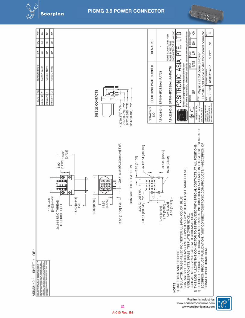
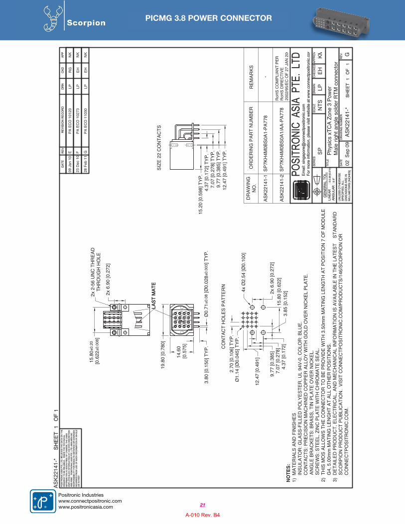
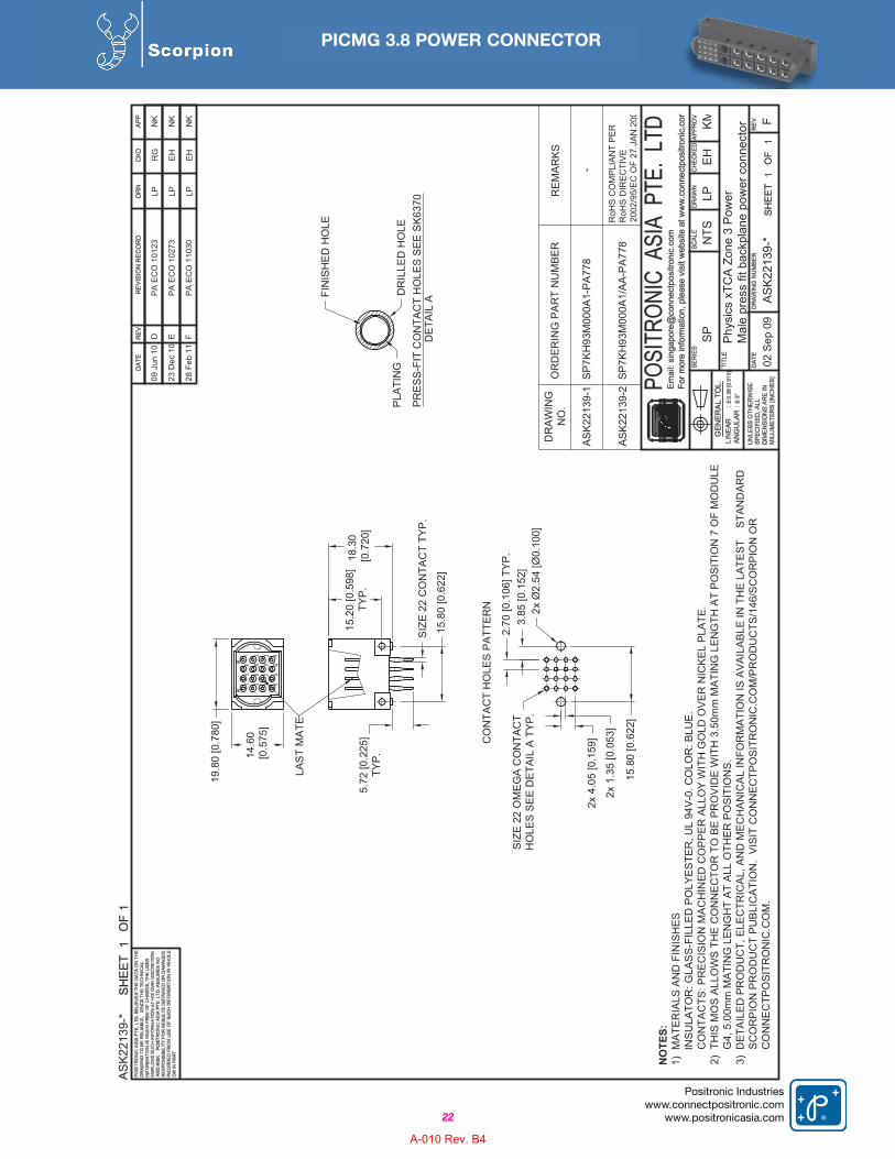
The PICMG 3.8 power connector has 16 contacts rated at 3 amperes each at a maximum temperature rise of 30 degrees C; all contacts energized. Contact resistance is 6 milliohms
maximum. The connector package offers blind mating capability and is only19.8 mm wide. Contact termination types include right angle solder and straight press-fit.
PICMG 3.8 POWER CONNECTOR
18
Positronic Industrieswww.connectpositronic.com
www.positronicasia.com
Positronic is proud to have participated in PICMG 3.8. The Scorpion series was chosen as the PICMG 3.8 power connector. For more information on the PICMG 3.8 connectors, see pages 19-22.
A-010 Rev. B4
PICMG 3.8 POWER CONNECTOR
19
Positronic Industrieswww.connectpositronic.comwww.positronicasia.com
1–
2–
3–
4–
5 6
ZP 0 1 6 F S 4 2 B
STEP
EXAMPLE
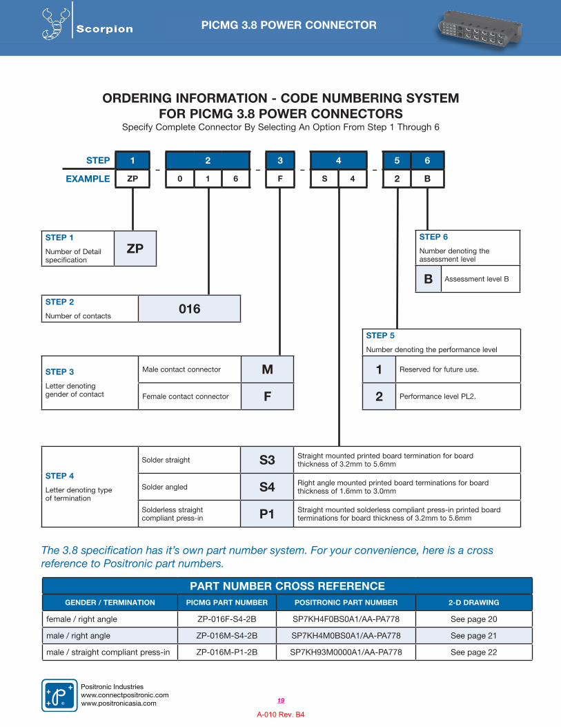
ORDERING INFORMATION - CODE NUMBERING SYSTEMFOR PICMG 3.8 POWER CONNECTORS
Specify Complete Connector By Selecting An Option From Step 1 Through 6
STEP 2
Number of contacts016
STEP 3
Letter denoting gender of contact
Male contact connector M
Female contact connector F
PART NUMBER CROSS REFERENCEGENDER / TERMINATION PICMG PART NUMBER POSITRONIC PART NUMBER 2-D DRAWING
female / right angle ZP-016F-S4-2B SP7KH4F0BS0A1/AA-PA778 See page 20
male / right angle ZP-016M-S4-2B SP7KH4M0BS0A1/AA-PA778 See page 21
male / straight compliant press-in ZP-016M-P1-2B SP7KH93M0000A1/AA-PA778 See page 22
STEP 5
Number denoting the performance level
1 Reserved for future use.
2 Performance level PL2.
STEP 6
Number denoting the assessment level
B Assessment level B
STEP 4
Letter denoting typeof termination
Solder straight S3 Straight mounted printed board termination for board thickness of 3.2mm to 5.6mm
Solder angled S4 Right angle mounted printed board terminations for board thickness of 1.6mm to 3.0mm
Solderless straightcompliant press-in P1 Straight mounted solderless compliant press-in printed board
terminations for board thickness of 3.2mm to 5.6mm
STEP 1
Number of Detail specification
ZP
The 3.8 specification has it’s own part number system. For your convenience, here is a cross reference to Positronic part numbers.
A-010 Rev. B4
ASK2
2140
-*1
1
SPN
TSLP
Phys
ics
xTC
A Zo
ne 3
Pow
er
03 S
EP 0
9AS
K221
40-*
11
G
Fem
ale
right
ang
le s
olde
r fro
nt b
oard
con
nect
o
EHKM
SIZE
22
CO
NTA
CTS
19.8
0 [0
.780
]
14.6
0 [0
.575
]
3.80
[0.1
50] T
YP.
Ø0.
71±0
.08
[Ø0.
028±
0.00
3 ] T
YP.
4.37
[0.1
72]
7.07
[0.2
78]
9.77
[0.3
85]
12.4
7 [0
.491
]2x
6.9
0 [0
.272
]
3.85
[0.1
52]
2.70
[0.1
06] T
YP.
Ø1.
14 [Ø
0.04
5] T
YP.
15.8
0 [0
.622
]
CO
NTA
CT
HO
LES
PATT
ERN
SIZE
22
CO
NTA
CTS
12.4
7 [0
.491
] TYP
.9.
77 [0
.385
] TYP
.7.
07 [0
.278
] TYP
.4.
37 [0
.172
] TYP
.
15.8
0±0.
20 [0
.622
±0.0
08]
6.90
[0.2
72]
18.6
2 [0
.733
]
4x Ø
2.54
[Ø0.
100]
DR
AWIN
GN
O.
ASK2
2140
-1
ASK2
2140
-2
OR
DER
ING
PAR
T N
UM
BER
REM
ARKS
RoH
S C
OM
PLIA
NT
PER
RoH
S D
IREC
TIVE
2002
/95/
EC O
F 27
JAN
200
-SP
7KH
4F0B
S0A1
-PA7
78
SP7K
H4F
0BS0
A1/A
A-PA
778
09 J
un 1
0E
PA E
CO
101
23LP
RG
NK
2x 2
-56
UN
C T
HR
EAD
THR
OU
GH
HO
LE
16.4
0 [0
.646
]TY
P.
04 M
ar 1
1G
PA E
CO
110
39LP
EHN
K
NOTE
S:1)
MAT
ERIA
LS A
ND
FIN
ISH
ESIN
SULA
TOR
: GLA
SS-F
ILLE
D P
OLY
ESTE
R, U
L 94
V-0.
CO
LOR
: BLU
E.C
ON
TAC
TS: P
REC
ISIO
N M
ACH
INED
CO
PPER
ALL
OY
WIT
H G
OLD
OVE
R N
ICKE
L PL
ATE.
ANG
LE B
RAC
KETS
: BR
ASS,
TIN
PLA
TE O
VER
NIC
KEL.
S
CR
EWS:
STE
EL, Z
INC
PLA
TE W
ITH
CH
RO
MAT
E SE
AL.
2)TH
IS M
OS
ALLO
WS
THE
CO
NN
ECTO
R T
O B
E PR
OVI
DED
WIT
H S
PEC
IAL
CO
NTA
CTS
AT
ALL
POSI
TIO
NS.
3)D
ETAI
LED
PR
OD
UC
T, E
LEC
TRIC
AL, A
ND
MEC
HAN
ICAL
INFO
RM
ATIO
N IS
AVA
ILAB
LE IN
TH
E LA
TEST
S
TAN
DAR
DSC
OR
PIO
N P
RO
DU
CT
PUBL
ICAT
ION
. VI
SIT
CO
NN
ECTP
OSI
TRO
NIC
.CO
M/P
RO
DU
CTS/
146/
SCO
RPI
ON
OR
CO
NN
ECTP
OSI
TRO
NIC
.CO
M.
23 D
ec 1
0F
PA E
CO
102
73LP
EHN
K
PICMG 3.8 POWER CONNECTOR
20
Positronic Industrieswww.connectpositronic.com
www.positronicasia.com
A-010 Rev. B4
ASK2
2141
-*1
1
SPN
TSLP
Phys
ics
xTC
A Zo
ne 3
Pow
er
02 S
ep 0
9AS
K221
41-*
11
G
Mal
e rig
ht a
ngle
sol
der R
TM c
onne
ctor
EHKM
12.4
7 [0
.491
] TYP
.9.
77 [0
.385
] TYP
.7.
07 [0
.278
] TYP
.4.
37 [0
.172
] TYP
.
4.37
[0.1
72]
7.07
[0.2
78]
9.77
[0.3
85]
12.4
7 [0
.491
]
2x 6
.90
[0.2
72]
2.70
[0.1
06] T
YP.
Ø1.
14 [Ø
0.04
5] T
YP.
15.8
0 [0
.622
]
CO
NTA
CT
HO
LES
PATT
ERN
19.8
0 [0
.780
]
14.6
0 [0
.575
]
3.80
[0.1
50] T
YP.
Ø0.
71±0
.08
[Ø0.
028±
0.00
3 ] T
YP.
SIZE
22
CO
NTA
CTS
4x Ø
2.54
[Ø0.
100]
3.85
[0.1
52]
15.8
0±0.
20 [0
.622
±0.0
08]
DR
AWIN
GN
O.
ASK2
2141
-1
ASK2
2141
-2
OR
DER
ING
PAR
T N
UM
BER
REM
ARKS
RoH
S C
OM
PLIA
NT
PER
RoH
S D
IREC
TIVE
2002
/95/
EC O
F 27
JAN
200
-SP
7KH
4M0B
S0A1
-PA7
78
SP7K
H4M
0BS0
A1/A
A-PA
778
2x 6
.90
[0.2
72]
09 J
an 1
0E
PA E
CO
101
23LP
RG
NK
2x 2
-56
UN
C T
HR
EAD
THR
OU
GH
HO
LE
LAST
MAT
ELA
ST M
ATE
15.2
0 [0
.598
] TYP
.
NOTE
S:1)
MAT
ERIA
LS A
ND
FIN
ISH
ESIN
SULA
TOR
: GLA
SS-F
ILLE
D P
OLY
ESTE
R, U
L 94
V-0.
CO
LOR
: BLU
E.C
ON
TAC
TS: P
REC
ISIO
N M
ACH
INED
CO
PPER
ALL
OY
WIT
H G
OLD
OVE
R N
ICKE
L PL
ATE.
ANG
LE B
RAC
KETS
: BR
ASS,
TIN
PLA
TE O
VER
NIC
KEL.
S
CR
EWS:
STE
EL, Z
INC
PLA
TE W
ITH
CH
RO
MAT
E SE
AL.
2)TH
IS M
OS
ALLO
WS
THE
CO
NN
ECTO
R T
O B
E PR
OVI
DE
WIT
H 3
.50m
m M
ATIN
G L
ENG
TH A
T PO
SITI
ON
7 O
F M
OD
ULE
G4,
5.0
0mm
MAT
ING
LEN
GH
T AT
ALL
OTH
ER P
OSI
TIO
NS.
3)D
ETAI
LED
PR
OD
UC
T, E
LEC
TRIC
AL, A
ND
MEC
HAN
ICAL
INFO
RM
ATIO
N IS
AVA
ILAB
LE IN
TH
E LA
TEST
S
TAN
DAR
DSC
OR
PIO
N P
RO
DU
CT
PUBL
ICAT
ION
. VI
SIT
CO
NN
ECTP
OSI
TRO
NIC
.CO
M/P
RO
DU
CTS
/146
/SC
OR
PIO
N O
RC
ON
NEC
TPO
SITR
ON
IC.C
OM
.
23 D
ec 1
0F
PA E
CO
102
73LP
EHN
K
28 F
eb 1
1G
PA E
CO
110
30LP
EHN
K
PICMG 3.8 POWER CONNECTOR
21
Positronic Industrieswww.connectpositronic.comwww.positronicasia.com
A-010 Rev. B4
AS
K22
139-
*1
1
SP
NTS
LP
Phy
sics
xTC
A Z
one
3 Po
wer
02 S
ep 0
9A
SK
2213
9-*
11
F
Mal
e pr
ess
fit b
ackp
lane
pow
er c
onne
ctor
EHK
M
NOTE
S:1)
MAT
ERIA
LS A
ND
FIN
ISH
ESIN
SU
LATO
R: G
LAS
S-F
ILLE
D P
OLY
ES
TER
, UL
94V-
0. C
OLO
R: B
LUE.
CO
NTA
CTS
: PR
EC
ISIO
N M
AC
HIN
ED
CO
PP
ER
ALL
OY
WIT
H G
OLD
OVE
R N
ICKE
L PL
ATE.
2)TH
IS M
OS
ALLO
WS
TH
E C
ON
NE
CTO
R T
O B
E P
RO
VID
E W
ITH
3.5
0mm
MAT
ING
LE
NG
TH A
T PO
SITI
ON
7 O
F M
OD
ULE
G4,
5.0
0mm
MA
TIN
G L
EN
GH
T A
T A
LL O
THE
R P
OS
ITIO
NS
.3)
DET
AILE
D P
RO
DU
CT,
ELE
CTR
ICA
L, A
ND
MEC
HA
NIC
AL
INFO
RM
ATIO
N IS
AVA
ILAB
LE IN
TH
E LA
TEST
S
TAN
DAR
DS
CO
RP
ION
PR
OD
UC
T P
UB
LIC
ATI
ON
. V
ISIT
CO
NN
ECTP
OSI
TRO
NIC
.CO
M/P
RO
DU
CTS
/146
/SC
OR
PIO
N O
RC
ON
NE
CTP
OS
ITR
ON
IC.C
OM
.
19.8
0 [0
.780
]
14.6
0 [0
.575
]
2x 1
.35
[0.0
53]
2x 4
.05
[0.1
59]
3.85
[0.1
52]
2.70
[0.1
06] T
YP
.
15.8
0 [0
.622
]
CO
NTA
CT
HO
LES
PAT
TER
N
18.3
0 [0
.720
]
15.8
0 [0
.622
]
2x Ø
2.54
[Ø0.
100]
5.72
[0.2
25]
TYP.
SIZ
E 22
OM
EG
A C
ON
TAC
TH
OLE
S S
EE D
ETAI
L A
TYP.
FIN
ISH
ED
HO
LE
PLA
TIN
GD
RIL
LED
HO
LE
DET
AIL
AP
RE
SS-F
IT C
ON
TAC
T H
OLE
S S
EE S
K637
0S
IZE
22 C
ON
TAC
T TY
P.
DR
AW
ING
NO
.
AS
K22
139-
1
AS
K22
139-
2
OR
DER
ING
PA
RT
NU
MBE
RR
EM
AR
KS
RoH
S C
OM
PLI
ANT
PER
RoH
S D
IREC
TIVE
2002
/95/
EC
OF
27 J
AN 2
00
-S
P7K
H93
M00
0A1-
PA
778
SP
7KH
93M
000A
1/A
A-P
A77
8
LAS
T M
ATE
15.2
0 [0
.598
]TY
P.
28 F
eb 1
1F
PA
ECO
110
30LP
EH
NK
09 J
un 1
0D
PA
ECO
101
23LP
RG
NK
23 D
ec 1
0E
PA
ECO
102
73LP
EH
NK
PICMG 3.8 POWER CONNECTOR
22
Positronic Industrieswww.connectpositronic.com
www.positronicasia.com
A-010 Rev. B4
NORTH AMERICAN SALES OFFICESUnited States, Springfield, MissouriFactory and Sales Office 800 641 4054 [email protected] Rico Sales Office 800 641 4054 [email protected] Sales Office 800 872 7674 [email protected] Sales Office 800 327 8272 [email protected]
EUROPEAN SALES OFFICESFrance, Auch Factory and Sales 33 (0) 5 6263 4491 [email protected] France Sales Office 33 (0) 1 4588 1388 [email protected] France Sales Office 33 (0) 4 6772 8028 [email protected] Sales Office 39 (0) 2 5411 6106 [email protected] Sales Office 49 (0) 23 5163 4739 [email protected] Kingdom Sales Office 44 (0) 7975 682 488 [email protected]
Europe & Middle East Technical Agents:Finland, United Kingdom, Scotland, Israel, Norway, Sweden, Turkey and the Ukraine.
ASIA/PACIFIC LOCATIONSSINGAPORE, Asia/Pacific Headquarters Factory Sales and Engineering Offices +65 6842 1419 [email protected]
ASIA, Direct Sales OfficesChina Factory - Zhuhai +86 756 3626 466 [email protected] Shenzhen +86 755 2601 0941 [email protected] Shanghai +86 158 2907 9779 [email protected] Xian Sales Office +86 029 8839 5306 [email protected] Beijing Sales Office +86 10 8203 7718 [email protected] Sales and Engineering Offices +81 3 5619 8072 [email protected]
India Factory Sales and Engineering Offices +91 20 2439 4810 [email protected] Bangalore Sales Office +91 94 4907 3251 [email protected] New Delhi Sales Office +91 98 6886 6826 [email protected]
Korea Sales Office +82 31 909 8047 [email protected] Sales Office +886 2 2937 8775 [email protected]
ASIA/PACIFIC, Technical AgentsTechnical Agents in Australia, Hong Kong, Malaysia, New Zealand, Philippines, Thailand and Vietnam.
POSITRONIC INDUSTRIES, INC423 N Campbell Avenue, P O Box 8247, Springfield, MO 65801, USATelephone: 1 417 866 2322Fax: 1 417 866 4115Email: [email protected]
POSITRONIC INDUSTRIES, SASZone Industrielle Est, 46 Route d’Engachies, F32020, Auch Cedex 9, FranceTelephone: 33 (0) 5 62 63 44 91Telecopieur: 33 (0) 5 62 63 51 17Email: [email protected]
POSITRONIC ASIA PTE LTD3014A Ubi Road 1 # 07-01 Singapore 408703Telephone: 65 6842 1419 Fax: 65 6842 1421
Email: [email protected]
www.connectpositronic.com
Mod
ula
r P
ow
er,
Sig
nal &
Shie
lded C
onta
ct
Connecto
rsS
CO
RP
ION
Seri
es
®
A-010 Rev. B4