river crossings: silvertown tunnel - london...
TRANSCRIPT

TRANSPORT FOR LONDON
RIVER CROSSINGS: SILVERTOWN TUNNEL
SUPPORTING TECHNICAL DOCUMENTATION
This report is part of a wider suite of documents which outline our approach to traffic, environmental, optioneering and engineering disciplines, amongst others. We would like to know if you have any comments on our approach to this work. To give us your views, please respond to our consultation at www.tfl.gov.uk/silvertown-tunnel
Please note that consultation on the Silvertown Tunnel is running from October – December 2014
SILVERTOWN CROSSING STUDY: TUNNEL
ENGINEERING
Mott MacDonald
June 2012
This report presents the subsequent studies of both bored tunnel and immersed tunnel crossings of the Thames at Silvertown.
Silvertown Crossing Study
Tunnel Engineering
June 2012Transport for London


298348 MNC TUN 001 A
C:\DOCUME~1\tuc06895\OTLocal\PiMS Live\Workbin\592E6A14.0\Silvertown Crossing Study Rev 001 draft for
16 December 2011
Silvertown Crossing Study
Tunnel Engineering
June 2012
Transport for London
Mott MacDonald, Mott MacDonald House, 8-10 Sydenham Road, Croydon CR0 2EE, United Kingdom T +44(0) 20 8774 2000 F +44 (0) 20 8681 5706, W www.mottmac.com
Windsor House, 42-50 Victoria Street, London SW1H OTL


Silvertown Crossing Study
Mott MacDonald, Mott MacDonald House, 8-10 Sydenham Road, Croydon CR0 2EE, United Kingdom T +44(0) 20 8774 2000 F +44 (0) 20 8681 5706, W www.mottmac.com
Revision Date Originator Checker Approver Description
001 24/02/2012 N Tucker /J Baber S Allen M Leggett Draft – for comment
002 22/06/2012 N Tucker/J Baber S Allen M Leggett Final - updated for comments
Issue and revision record
This document is issued for the party which commissioned it and for specific purposes connected with the above-captioned project only. It should not be relied upon by any other party or used for any other purpose.
We accept no responsibility for the consequences of this document being relied upon by any other party, or being used for any other purpose, or containing any error or omission which is due to an error or omission in data supplied to us by other parties.
This document contains confidential information and proprietary intellectual property. It should not be shown to other parties without consent from us and from the party which commissioned it.


298348/MNC/TUN/001/B 22/06/2012 C:\DOCUME~1\BAB58876\OTLocal\PIMS LIVE\Workbin\59C11FC7.0\Silvertown Crossing Study Rev 002.doc
Silvertown Crossing Study
Chapter Title Page
Executive Summary i
1. Introduction 1 1.1 Background________________________________________________________________________ 1 1.2 Scope of this report__________________________________________________________________ 2 1.2.1 Bored tunnel _______________________________________________________________________ 2 1.2.2 Immersed Tunnel ___________________________________________________________________ 3 1.3 Report structure ____________________________________________________________________ 3 1.4 Contributors _______________________________________________________________________ 3
2. Project Constraints 4 2.1 Greenwich Peninsula Development _____________________________________________________ 4 2.2 London Cable Car (LCC) _____________________________________________________________ 4 2.3 Gas Works Foundations ______________________________________________________________ 5 2.4 River Flood Walls ___________________________________________________________________ 5 2.5 Land Ownership ____________________________________________________________________ 5 2.6 Connections to A102 Blackwall Approach ________________________________________________ 6 2.7 Gas Holder ________________________________________________________________________ 6 2.8 DLR Viaduct _______________________________________________________________________ 6 2.9 DLR Thames Wharf Station ___________________________________________________________ 6 2.10 JLE Future Extension ________________________________________________________________ 6 2.11 Royal Victoria Dock Western Entrance ___________________________________________________ 6 2.12 Royal Victoria Dock Drainage __________________________________________________________ 7 2.13 Land Use__________________________________________________________________________ 7 2.14 Project Location ____________________________________________________________________ 7
3. Geotechnical 9 3.1 General ___________________________________________________________________________ 9 3.1.1 Topography________________________________________________________________________ 9 3.1.2 Regional Geology ___________________________________________________________________ 9 3.1.3 Scour Hollows______________________________________________________________________ 9 3.1.4 Hydrogeology ______________________________________________________________________ 9 3.1.5 Expected Ground Conditions _________________________________________________________ 10 3.1.6 Geological Overview of the Greenwich Peninsula _________________________________________ 12 3.1.7 Geological Overview of the London Borough of Newham Silvertown Area_______________________ 12 3.2 Geotechnical Implications for Bored Tunnel ______________________________________________ 13 3.2.1 TBM Selection & Specification ________________________________________________________ 14 3.2.2 Cross Passages ___________________________________________________________________ 14 3.2.3 Low Point Sump ___________________________________________________________________ 14 3.2.4 Cut and Cover_____________________________________________________________________ 15 3.2.5 Open Cut Ramps __________________________________________________________________ 15 3.3 Geotechnical Implications for Immersed Tube Tunnel ______________________________________ 15 3.3.1 The Dredged Trench________________________________________________________________ 15 3.3.2 Marine Temporary Works ____________________________________________________________ 16 3.3.3 Control of settlements _______________________________________________________________ 16
Content

298348/MNC/TUN/001/B 22/06/2012 C:\DOCUME~1\BAB58876\OTLocal\PIMS LIVE\Workbin\59C11FC7.0\Silvertown Crossing Study Rev 002.doc
Silvertown Crossing Study
3.3.4 The Casting Basin__________________________________________________________________ 16 3.3.5 Cut and cover tunnels _______________________________________________________________ 17 3.3.6 Open Cut Ramps __________________________________________________________________ 17 3.3.7 Re-use of materials_________________________________________________________________ 17
4. Bored Tunnel – Design Criteria 18 4.1 General __________________________________________________________________________ 18 4.2 Alignment Development _____________________________________________________________ 18 4.3 Design Criteria ____________________________________________________________________ 19 4.3.1 Design Speed and Stopping Site Distance _______________________________________________ 19 4.3.2 Carriageway Dimensions ____________________________________________________________ 19 4.3.3 Super Elevation____________________________________________________________________ 20 4.3.4 Gradient _________________________________________________________________________ 20 4.4 Tunnel Diameter ___________________________________________________________________ 20 4.5 Minimum Alignment Plan Radius ______________________________________________________ 20 4.6 Minimum Tunnel Crown Cover ________________________________________________________ 20 4.7 Traffic, Equipment and Structure Gauge_________________________________________________ 21 4.7.1 Vertically _________________________________________________________________________ 21 4.7.2 Horizontally _______________________________________________________________________ 21 4.8 Cross Passages ___________________________________________________________________ 21 4.9 Cross Passage Sump _______________________________________________________________ 21 4.10 Tunnel Linings_____________________________________________________________________ 22 4.11 Tunnel Ventilation __________________________________________________________________ 22
5. Bored Tunnel – Environmental Issues 24 5.1 Air Quality ________________________________________________________________________ 24 5.2 Archaeology ______________________________________________________________________ 25 5.3 Biodiversity _______________________________________________________________________ 25 5.4 Ground Contamination ______________________________________________________________ 26 5.4.1 Greenwich________________________________________________________________________ 26 5.4.2 Newham _________________________________________________________________________ 27 5.5 Heritage _________________________________________________________________________ 27 5.6 Landscape & Townscape ____________________________________________________________ 27 5.7 Noise & Vibration __________________________________________________________________ 28 5.8 Waste Management ________________________________________________________________ 29 5.9 Water Resources and Flood Protection _________________________________________________ 30 5.9.1 Surface Water_____________________________________________________________________ 30 5.9.2 Flood Risk________________________________________________________________________ 30 5.9.3 Groundwater ______________________________________________________________________ 31 5.10 Sustainability______________________________________________________________________ 32
6. Bored Tunnel - Fire Life Safety 34 6.1 Introduction _______________________________________________________________________ 34 6.2 Consultations with London Fire Brigade _________________________________________________ 34 6.3 Worst Case Fire Scenario____________________________________________________________ 55 6.3.1 Tunnel Ventilation Strategy___________________________________________________________ 55 6.4 Design Fire Size ___________________________________________________________________ 55 6.4.1 Range of Vehicle Fire Sizes __________________________________________________________ 55 6.4.2 Comparison with selected UK tunnels __________________________________________________ 55

298348/MNC/TUN/001/B 22/06/2012 C:\DOCUME~1\BAB58876\OTLocal\PIMS LIVE\Workbin\59C11FC7.0\Silvertown Crossing Study Rev 002.doc
Silvertown Crossing Study
6.4.3 Recommended Design Fire Size ______________________________________________________ 55 6.5 CFD Modelling ____________________________________________________________________ 55 6.5.1 CFD Results ______________________________________________________________________ 55 6.5.2 Influence of Cross Passage Spacing ___________________________________________________ 55 6.6 Evacuation Analysis ________________________________________________________________ 55 6.6.1 Vehicle Mix and Occupancy__________________________________________________________ 55 6.6.2 Detection and Alarm Times___________________________________________________________ 55 6.6.3 Pre-Movement Time ________________________________________________________________ 55 6.6.4 Movement Time ___________________________________________________________________ 55 6.6.5 Overall Evacuation Timescales________________________________________________________ 55 6.6.6 STEPS Evacuation Simulation ________________________________________________________ 55 6.7 Fire Brigade Intervention_____________________________________________________________ 55 6.7.1 Alerting the Fire Brigade _____________________________________________________________ 55 6.7.2 Fire Brigade Arrival _________________________________________________________________ 55 6.7.3 Dynamic Risk Assessment ___________________________________________________________ 55 6.7.4 Immediate Response _______________________________________________________________ 55 6.7.5 Influence of Cross Passage Spacing ___________________________________________________ 55 6.8 Tunnel Facilities ___________________________________________________________________ 55 6.8.1 Emergency equipment at safety niches and cross passages _________________________________ 55 6.8.2 Traffic surveillance and incident detection systems ________________________________________ 55 6.8.3 Traffic control systems ______________________________________________________________ 55 6.8.4 Communications and warning systems__________________________________________________ 55 6.8.5 Emergency escape routes ___________________________________________________________ 55 6.8.6 Provisions for disabled persons _______________________________________________________ 55 6.8.7 Tunnel and cross passage ventilation___________________________________________________ 55 6.8.8 Drainage system___________________________________________________________________ 55 6.8.9 Structural fire protection _____________________________________________________________ 55 6.8.10 Fire suppression system _____________________________________________________________ 55 6.8.11 Emergency services access and facilities________________________________________________ 55 6.9 Key Issues _______________________________________________________________________ 55
7. Bored Tunnel - Constructability 56 7.1 Running Tunnels___________________________________________________________________ 56 7.2 Tunnel Boring Machine (TBM) Selection ________________________________________________ 56 7.2.1 Slurry TBM _______________________________________________________________________ 57 7.2.2 EPBM ___________________________________________________________________________ 57 7.2.3 TBM Choice ______________________________________________________________________ 58 7.2.4 TBM Features _____________________________________________________________________ 58 7.3 Cut and Cover Tunnels ______________________________________________________________ 58 7.4 Retained Cut Ramps________________________________________________________________ 59 7.5 TBM Drive Strategy_________________________________________________________________ 59 7.6 TBM Delivery _____________________________________________________________________ 61 7.7 TBM Build and Erection _____________________________________________________________ 61 7.8 TBM Reversal and Removal __________________________________________________________ 62 7.9 TBM Logistics _____________________________________________________________________ 62 7.10 TBM Launch Box Configuration and its Effect on Tunnel Logistics_____________________________ 62 7.11 Surface Logistics Segment Delivery and Spoil Disposal_____________________________________ 63 7.11.1 Segment Supply ___________________________________________________________________ 63 7.11.2 Spoil Disposal _____________________________________________________________________ 63 7.11.3 Site Layout and Logistics ____________________________________________________________ 64

298348/MNC/TUN/001/B 22/06/2012 C:\DOCUME~1\BAB58876\OTLocal\PIMS LIVE\Workbin\59C11FC7.0\Silvertown Crossing Study Rev 002.doc
Silvertown Crossing Study
7.12 Impact on River Environment _________________________________________________________ 65 7.13 Work Sites and Land Requirements ____________________________________________________ 65 7.13.1 Site layouts _______________________________________________________________________ 66
8. Cross Passage Construction Methodology 68 8.1 Emergency Cross Passages__________________________________________________________ 68 8.1.1 Cross passage Ground Treatment _____________________________________________________ 69 8.1.2 Sequence and Construction __________________________________________________________ 70 8.2 Low Point Sump ___________________________________________________________________ 71 8.3 Cross Passages Construction Case Histories_____________________________________________ 72
9. Bored Tunnel – Construction Programme 74 9.1 Construction Programme ____________________________________________________________ 74
10. Bored Tunnel – Cost Estimate 77 10.1 Cost Estimate _____________________________________________________________________ 77
11. Immersed Tube Tunnel – Design Solution 81 11.1 General __________________________________________________________________________ 81 11.2 Alignment Development _____________________________________________________________ 82 11.3 Structural Form ____________________________________________________________________ 83 11.3.1 Immersed Tube Tunnel______________________________________________________________ 83 11.3.2 Cut and Cover Tunnels ______________________________________________________________ 84 11.3.3 Ramps __________________________________________________________________________ 84 11.4 Tunnel Finishes____________________________________________________________________ 85 11.5 Service Buildings __________________________________________________________________ 85 11.6 Design Options ____________________________________________________________________ 85 11.6.1 Omission of Central Escape Gallery ____________________________________________________ 85
12. Immersed Tube Tunnel - Design Criteria 86 12.1 General __________________________________________________________________________ 86 12.2 Alignment ________________________________________________________________________ 86 12.3 Carriageway Clearances_____________________________________________________________ 87 12.4 Super Elevation____________________________________________________________________ 87 12.5 Gradient _________________________________________________________________________ 87 12.6 Navigation Clearances ______________________________________________________________ 87 12.7 Vertical Stability and Buoyancy________________________________________________________ 88 12.8 Hydrographic Parameters ____________________________________________________________ 88 12.9 Watertightness ____________________________________________________________________ 89 12.10 Flood Protection ___________________________________________________________________ 89 12.11 Accidental Loads___________________________________________________________________ 89 12.12 Structural Design __________________________________________________________________ 90 12.13 Tunnel Ventilation __________________________________________________________________ 90 12.14 Consultations with the PLA ___________________________________________________________ 90
13. Immersed Tube Tunnel – Environmental Issues 92 13.1 Air Quality ________________________________________________________________________ 92 13.2 Archaeology ______________________________________________________________________ 92
298348/MNC/TUN/001/B 22/06/2012 C:\DOCUME~1\BAB58876\OTLocal\PIMS LIVE\Workbin\59C11FC7.0\Silvertown Crossing Study Rev 002.doc
Silvertown Crossing Study
13.3 Biodiversity _______________________________________________________________________ 92 13.4 Ground Contamination ______________________________________________________________ 93 13.5 Heritage _________________________________________________________________________ 93 13.6 Landscape & Townscape ____________________________________________________________ 94 13.7 Noise & Vibration __________________________________________________________________ 94 13.8 Waste Management ________________________________________________________________ 94 13.9 Water Resources and Flood Protection _________________________________________________ 94 13.9.1 Dredging _________________________________________________________________________ 94 13.9.2 Surface Water_____________________________________________________________________ 94 13.9.3 Flood Risk________________________________________________________________________ 95 13.9.4 Groundwater ______________________________________________________________________ 96 13.10 River Dynamics____________________________________________________________________ 96 13.10.1 Temporary Cofferdams ______________________________________________________________ 96 13.10.2 Dredging _________________________________________________________________________ 97
14. Immersed Tube Tunnel - Fire Life Safety 98 14.1 Introduction _______________________________________________________________________ 98 14.1.1 Evacuation and Intervention Options using the Central Cell __________________________________ 98 14.2 CFD Modelling ___________________________________________________________________ 100 14.2.1 CFD Results _____________________________________________________________________ 101 14.3 Evacuation Analysis _______________________________________________________________ 105 14.4 Key Issues ______________________________________________________________________ 105
15. Immersed Tube Tunnel - Constructability 106 15.1 Overview________________________________________________________________________ 106 15.2 Selection of Tunnel Element Construction Site___________________________________________ 106 15.2.1 Purpose Built Casting Basins ________________________________________________________ 107 15.2.2 Operational Dry Docks _____________________________________________________________ 108 15.2.3 Disused Dry Docks ________________________________________________________________ 109 15.2.4 Use of Tunnel Approaches __________________________________________________________ 110 15.2.5 Towing Elements from a Remote Site__________________________________________________ 111 15.3 Land Works______________________________________________________________________ 112 15.3.1 Greenwich Worksite _______________________________________________________________ 112 15.3.2 Construction of Cut & Cover Tunnels - Greenwich ________________________________________ 113 15.3.3 Silvertown Approach Worksite _______________________________________________________ 114 15.3.4 Construction of Cut & Cover Tunnels - Silvertown ________________________________________ 116 15.3.5 Casting Basin Worksite_____________________________________________________________ 116 15.3.6 Construction of Tunnel Elements _____________________________________________________ 118 15.4 River Works _____________________________________________________________________ 119 15.4.1 Installing Cofferdams ______________________________________________________________ 120 15.4.2 Protection to Cable Car_____________________________________________________________ 122 15.4.3 Dredging ________________________________________________________________________ 123 15.4.4 Tunnel Element Immersion __________________________________________________________ 128 15.4.5 Backfilling _______________________________________________________________________ 132 15.4.6 Impact of River Works on Navigation __________________________________________________ 134 15.5 Impact to Stakeholders _____________________________________________________________ 135 15.6 Impact on Wharf Operations _________________________________________________________ 135 15.6.1 Greenwich Wharfage ______________________________________________________________ 136 15.6.2 Silvertown Wharfs _________________________________________________________________ 137

298348/MNC/TUN/001/B 22/06/2012 C:\DOCUME~1\BAB58876\OTLocal\PIMS LIVE\Workbin\59C11FC7.0\Silvertown Crossing Study Rev 002.doc
Silvertown Crossing Study
16. Immersed Tube Tunnel – Construction Programme 140 16.1 Construction Programme ___________________________________________________________ 140
17. Immersed Tube Tunnel – Cost Estimate 143 17.1 Cost Estimate ____________________________________________________________________ 143
18. Ancillary Works 148 18.1 Tunnel Services Buildings___________________________________________________________ 148 18.2 Power Systems___________________________________________________________________ 148
19. Quantified Risk Assessment 149 19.1 Background______________________________________________________________________ 149 19.1.1 Summary of the Process____________________________________________________________ 149 19.2 Project Risks_____________________________________________________________________ 151 19.3 Project Opportunities ______________________________________________________________ 153 19.4 Quantified Risk Assessment Results __________________________________________________ 155 19.4.1 Opportunities identified for immersed tunnel_____________________________________________ 158 19.5 Quantified Risk Assessment – Modelling Notes __________________________________________ 158
20. Conclusions & Recommendations 167 20.1 Conclusions _____________________________________________________________________ 167 20.1.1 Bored tunnel _____________________________________________________________________ 167 20.1.2 Immersed Tunnel _________________________________________________________________ 167 20.1.3 Programme ______________________________________________________________________ 168 20.1.4 Cost ___________________________________________________________________________ 169 20.2 Recommendations ________________________________________________________________ 169
Appendices 171 Appendix A. Drawings________________________________________________________________________ 172 Appendix B. Bored Tunnel Construction Programme ________________________________________________ 175 Appendix C. ITT Construction Programme ________________________________________________________ 177 Appendix D. QRA Risk Register ________________________________________________________________ 179 Appendix E. CFD Modelling ___________________________________________________________________ 191 E.1. Introduction ______________________________________________________________________ 191 E.2. Model Geometry __________________________________________________________________ 191 E.2.1. Bored Tunnel ____________________________________________________________________ 191 E.2.2. Immersed Tube Tunnel_____________________________________________________________ 192 E.3. Fire Source Properties _____________________________________________________________ 193 E.4. Boundary Conditions_______________________________________________________________ 193 E.5. Tenability Criteria _________________________________________________________________ 193 Appendix F. Minutes of Meetings _______________________________________________________________ 195 Appendix F. 196 Appendix G. Reference Documents _____________________________________________________________ 206

298348/MNC/TUN/001/B 22/06/2012 C:\DOCUME~1\BAB58876\OTLocal\PIMS LIVE\Workbin\59C11FC7.0\Silvertown Crossing Study Rev 002.doc
i
Silvertown Crossing Study
The Silvertown Crossing studies undertaken to date have focussed on a bored tunnel solution with a number options being considered. This study has refined the bored tunnel solution, looking particularly at the issue of cross passages and fire life safety, based on a preferred solution defined by TfL. It has also looked at an immersed tunnel option for the crossing to determine if this is technically feasible and to identify the environmental impacts and impacts to navigation that might determine whether such as option is viable.
Bored Tunnel
Following a review of the previously proposed approach the fundamental tunnel layout of providing emergency escape for tunnel users within the main tunnel bore against the direction of traffic flow and ventilation has been maintained together with a maximum gradient of 4%.
Cross passage construction has been reviewed and it has been determined that cross-passages would be constructed from within the running tunnels. Ground treatment (i.e. grouting & dewatering) would be required but cross passage construction below the river banks and under the river Thames itself is considered feasible. The proposed scheme has been developed on the basis of providing cross-passages at 100m centres as guided by BD78/99 and the London Fire Brigade. There remains an opportunity to reduce the number of cross-passages should mitigation measures acceptable to the LFB be provided.
Immersed Tunnel
The immersed tunnel scheme developed uses the same horizontal alignment at the bored tunnel but has a shallower vertical alignment. The immersed tunnel is formed from four tunnel elements that are constructed in a purpose built casting basin located on the Silvertown approach. Temporary cofferdams are required in the foreshore to enable the immersed tunnel to connect to the cut and cover tunnels, and to serve as an entrance to the casting basin on the Silvertown side.
The land that has been safeguarded by TfL for the project is sufficient for the construction of the permanent works and for siting the casting basin.
The construction method requires the installation of cofferdam in the foreshores, dredging of a trench in the river bed, floating, manoeuvring and immersion of the four tunnel elements, and then backfilling around and above the completed tunnel structure. These works will have an impact on the river users and in particular the immersion of tunnel elements requires short term closure of the river. The various operations have
Executive Summary

298348/MNC/TUN/001/B 22/06/2012 C:\DOCUME~1\BAB58876\OTLocal\PIMS LIVE\Workbin\59C11FC7.0\Silvertown Crossing Study Rev 002.doc
ii
Silvertown Crossing Study
been discussed with the Port of London Authority. The PLA have identified a number of constraints that would need to be considered for the construction, but have not raised an overriding objection to the immersed tunnel. It is expected that closures can be managed and safe navigation be maintained during construction, subject to appropriate planning.
A high level environmental appraisal has been undertaken for the immersed tunnel and has identified some key areas that would need to be resolved with the Environment agency. The temporary loss of habitat on the foreshores is a major concern and compensation measures will need to be agreed. The affect on the river dynamics due to the foreshore cofferdams and the dredged trench will require numerical modelling to accurately predict the effect on current flows and determine the extent of erosion and deposition within the river. Dredging work will need to be licensed and comply with criteria for turbidity and oxygen levels. To avoid impact to fish spawning such works will need to be undertaken during the winter season.
A Fire life Safety review has been undertaken for the immersed tunnel. Longitudinal ventilation is expected to be feasible although there are slight differences in the build up of heat and smoke in the tunnel compared to the bored tunnel solution, due to the different cross section of the tunnel structure. The immersed tunnel is provided with a central gallery that offers some enhanced flexibility compared to the bored tunnel for evacuation and intervention as well as for general operation and maintenance.
Programme
The programme for the bored tunnel option is 52 months and follows from the decision to drive the twin bore tunnel from Silvertown to Greenwich, to rotate the TBM at Greenwich to reverse its direction and subsequently to drive the TBM back to Silvertown where the TBM will be dismantled. This is a decision that is principally a programme decision as it is quicker to rotate the TBM and drive it back the other way than to totally disassemble it, transport it and rebuild it. Establishing the launch chamber at the earliest possible time to enable the construction of the bored tunnel is the main programme driver for the early part of the bored tunnel programme.
The programme for the immersed tunnel is 48 months which is common for a scheme of this size. This takes into account the constraints of dredging only during the winter months. The programme is driven by the sequential activities of building the tunnel elements in the Silvertown approach at the same time as the Greenwich cut and cover tunnel, then immersing the tunnel elements and completing the Silvertown cut and cover tunnel afterwards. If a contractor decided to build the tunnel elements remotely there could be some significant programme savings.

298348/MNC/TUN/001/B 22/06/2012 C:\DOCUME~1\BAB58876\OTLocal\PIMS LIVE\Workbin\59C11FC7.0\Silvertown Crossing Study Rev 002.doc
iii
Silvertown Crossing Study
Cost
The cost of the bored tunnel is expected to £337m. This is the base cost for the scheme without risk applied. The QRA exercise has modelled the various risks that have been identified and concludes the mean cost for the scheme is likely to be £386m.
The cost of the immersed tunnel is expected to £390m. This is the base cost for the scheme without risk applied. The QRA exercise has modelled the various risks that have been identified and concludes the mean cost for the scheme is likely to be £446m.
This analysis shows the bored tunnel to be slightly cheaper than the immersed tunnel. This is primarily because the immersed tunnel includes lengthy cut and cover tunnels at each approach, to match the portal positions of the bored tunnel, and there is a high cost associated with the provision of a casting basin at Silvertown in which to build the tunnel elements.
A number of cost saving opportunities have been identified for the immersed tunnel, including reducing the length of cut and cover tunnels, and building the tunnel elements off-site. If these opportunities could be realised the immersed tunnel has the potential to become the cheaper scheme.
Conclusions
Both immersed and bored tunnel crossings of the River Thames at Silvertown are feasible. For the immersed tunnel navigation issues are believed to be manageable but some significant environmental issues still need to be resolved. The programmes for construction are broadly similar with the immersed tunnel being slightly faster. The bored tunnel; appears to offer a cheaper solution, depending on whether certain opportunities can be realised for the immersed tunnel.
This report provides TfL with a basis to evaluate cost and risk of each solution and determine a strategy for further development of a preferred scheme, for continued consultations with stakeholders and for procurement of the crossing.

298348/MNC/TUN/001/B 22/06/2012 C:\DOCUME~1\BAB58876\OTLocal\PIMS LIVE\Workbin\59C11FC7.0\Silvertown Crossing Study Rev 002.doc
1
Silvertown Crossing Study
1.1 Background
In November 2009 Mott MacDonald was commissioned to develop options for a bored tunnel road link across the river Thames to link Greenwich and Silvertown. Refer to Mott MacDonald report; New Thames River Crossing, Silvertown Tunnel Option – Volume 1, Rev 001, dated 30th November 2009.
The Option 1 presented was for a 2-lane twin TBM bored tunnel with eleven 3.75m ID cross-passages at approximately 100m centres. The lining was an 11.0m ID pre-cast concrete segmental lining. Approach structures (open cut and cut and cover tunnels) together with a ventilation station and stack were provided at each portal. A primary tunnel services building (single storey ~30m x 25m) was indicated at the Greenwich side and a secondary tunnel services building (single storey ~25m x 10m) was indicated at the Silvertown side.
In October 2010 further options were considered and presented in the report; New Thames River Crossing, Silvertown Tunnel Option – Addendum to Volume 1, Rev 1.0, dated 7th October 2010. The following options were considered:
• Option 2 – with emergency escape through tunnel invert.
• Option 3 – with emergency escape through the tunnel and with pedestrian access provided in one of the tunnels.
• Option 4 – with emergency escape through tunnel invert (with departures from BD 78/99).
• Option 5 – with emergency escape at road deck level in fire hardened housing.
• Option 6 – with emergency escape at road deck level in fire hardened housing (with departures from BD 78/99).
• Option 7 – fire suppression system with two cross passages only.
The study concluded that Option 5 should be the preferred scheme (assuming that there is no requirement to provide pedestrian access through the tunnel).
In January 2011 further alignments were considered and presented in the report; New Thames River Crossing, Silvertown Tunnel Option – Alignment Development, Rev 1.0, dated 10th January 2011.
In this report Option 5 was developed to include a twin bore uni-directional 2-lane tunnel not accessible to pedestrians or cyclists. In the event of an incident users would escape via a fire-hardened housing at road level. The alignment was amended to take account of the London Cable Car (LCC) project and the nature of the western entrance to the Royal Victoria Dock.
Following informal discussions between Mott MacDonald and TfL it was determined that the bored tunnel scheme most likely to prove acceptable to TfL and the safety authorities would be a design that is essentially a hybrid of the developed options and that encompasses the following:
1. Introduction

298348/MNC/TUN/001/B 22/06/2012 C:\DOCUME~1\BAB58876\OTLocal\PIMS LIVE\Workbin\59C11FC7.0\Silvertown Crossing Study Rev 002.doc
2
Silvertown Crossing Study
• Emergency escape for tunnel users within the main tunnel bore against the direction of traffic flow and ventilation i.e. no narrow escape passages along the tunnel.
• Intervention passages for the emergency services at approximately 500m intervals, allowing for two cross-passages within the bored tunnel section below the river bank. Greater cross-passage spacing could be mitigated by the provision of a fire suppression system as described in Option 7.
• A maximum gradient of 4%.
Due to the perceived significant negative impact on navigation in the Thames during construction and the environmental impacts of an immersed tube tunnel (ITT), only bored tunnel options were considered in the above reports.
However, an immersed tube tunnel option allows the shallowest crossing of the Thames, a significant consideration because of the constrained approach length on both banks of the river, and TfL has subsequently commissioned Mott MacDonald to carry out a further feasibility study to refine the bored tunnel options and consider an alternative immersed tube tunnel option to provide sufficient information for a decision on the preferred option to be taken.
1.2 Scope of this report
This report presents the subsequent studies of both bored tunnel and immersed tunnel crossings of the Thames at Silvertown commission by TfL in December 2011. Both tunnel options are required to fit with the constraints posed by the existing and proposed developments, including the cable car which crosses in a similar alignment and which includes foundations relatively close to the tunnel. In all options the portals would include a section of cut-and-cover tunnelling close to each portal. On the Silvertown side a section of open cut construction would be provided beyond the tunnel portal.
The scope for the studies is as follows:
1.2.1 Bored tunnel
The key aspects that were required to be investigated are: � Emergency escape for tunnel occupants utilising cross passages i.e. no dedicated escape passage
along the tunnel, allowing a tunnel diameter of circa 12.1m. � Consideration of intervention passages at approximately 500m intervals � Maximum gradient of 4%
Specific deliverables required are: � A cost estimate to be undertaken in collaboration with a relevant civil engineering contractor; � Quantified risk assessment; � A fire life safety strategy appropriate for this stage, including sufficient risk assessment of the proposed
design to allow discussions to be held with the London Fire Brigade; � A review of the proposed worksites for suitability for the construction method assumed, and access to
principal plant and tunnel service buildings; � A plan of the land required for construction and implementation of the tunnel.

298348/MNC/TUN/001/B 22/06/2012 C:\DOCUME~1\BAB58876\OTLocal\PIMS LIVE\Workbin\59C11FC7.0\Silvertown Crossing Study Rev 002.doc
3
Silvertown Crossing Study
The issues regarding the interval for escape passages are described in the fire life safety chapter, along with the conclusions from our discussions with LFB. The issues arising with the construction of the cross passages are dealt with in the chapter on constructability. For completeness we have also included a high level environmental appraisal for the bored tunnel based on previous studies and have summarised the design criteria used in developing the bored tunnel solution.
1.2.2 Immersed Tunnel
The key aspects that were required to be investigated are: � Follow essentially the same alignment of the bored tunnel scheme provided; � Provide two full highway gauge running lanes in each direction; � Maintain adequate clearances from the cable car foundations; � Show the extent of river works required during construction, including (but not limited to) the extent of
trench excavation required (area, depth, duration of works), impact on river flood defences, impact on operability of river wharfage;
� Show the extent of landside works to accommodate the immersed tube and cut and cover approaches � Engage with the Environment Agency to establish the flood risk for the design life of the asset.
Specific deliverables required are: � An outline design for an immersed tunnel crossing � An assessment of the construction on river dynamics; � An assessment of the impact of construction on river navigation; � A high level environmental appraisal of the construction, in particular as regards the ecology of the River
Thames; � Cost estimate to be undertaken in collaboration with a relevant civil engineering contractor; � Quantified risk assessment; � a fire life safety strategy* appropriate for this stage, including sufficient risk assessment of the proposed
design to allow discussions to be held with the London Fire Brigade;
1.3 Report structure
For a comprehensive understanding of the external factors influencing both the bored tunnel solution and the immersed tunnel solution that has been developed, we have included general chapters on project constraints and geotechnical conditions at the start of the report. Thereafter we have presented the bored tunnel solution followed by the immersed tunnel solution, with a combined QRA chapter at the end of the report.
This report does not include highway engineering at each portal or traffic modelling.
1.4 Contributors
This report has been drafted by Mott MacDonald in collaboration with London Bridge Associates (LBA) who has provided input for construction methodology, programming and cost estimation. Specialist contractors including Van Oord (dredging), Strukton Mergor (tunnel element immersion) and Vinci have been consulted for specialist advice. DS&A Risk Analytics has facilitated the Quantified Risk Assessment Process (QRA) and provided input to the QRA section of the report.

298348/MNC/TUN/001/B 22/06/2012 C:\DOCUME~1\BAB58876\OTLocal\PIMS LIVE\Workbin\59C11FC7.0\Silvertown Crossing Study Rev 002.doc
4
Silvertown Crossing Study
The tunnel options are required to fit with the constraints posed by the existing and proposed developments. Key constraints are identified below;
2.1 Greenwich Peninsula Development
The Greenwich Peninsular is an area set for heavy development to high environmental standards. 10,000 homes plus offices and public spaces have been proposed. There is close proximity of some of these structures to the tunnel safeguarding boundary as such should the boundary need to be extended it will have to be assessed against the impact on development plans. The details are indicated on the Landscape Master plan drawing 2338/LD/001 Rev 0. Maximum proposed building heights are shown on the Greenwich Peninsula Cable Car Area Masterplan, DEW 7C PA – 03-150.
Surface structures could be sited within portals to minimise visual impact and approaches could incorporate noise barriers to minimise the effect on surrounding structures. Dependant on the timing of the tunnel construction relative to future development, work areas should be carefully planned to minimise impact on homes and businesses.
2.2 London Cable Car (LCC)
The proposed London Cable Car (LCC) and ship impact protection (SIP) foundation structures significantly influence the alignment of the tunnel, which has been altered to maintain a minimum clear distance of 6.5m between any LCC & SIP foundation piles and the extrados of the tunnel.
The minimum clear distances to the tunnel alignment are expected to be as follows:
• North Intermediate Tower – 14.0m
• South Main Tower – 14.9m
• South Cable Car Station & South Compression Tower– 6.5m
• Ship impact protection – 19.0m
Details of the London Cable Car Project are indicated on the following drawings:
• Cable Profile, Cable Profile and Tower Heights, 001-AR-AED-DWG-0601010- Rev 10.
• North Station (Drive Station), Site Plan, 002-AR-AED-DWG-0601021 - Rev 8.
• North Station, Kiosk and Substation Buildings, 002-AR-AED-DWG-0601125 –Rev 7.
• North Station & North Compression Tower, Pile layout & Reference Table, 002-CS-URS-DWG-0200011 – Rev 10.
• North Tower General Arrangement, 004-CS-BHD-DWG-0300001 Rev C4
• North Tower, Foundation General Arrangement, 004-C5-BHD-DWG-0300002- Rev C2.
2. Project Constraints

298348/MNC/TUN/001/B 22/06/2012 C:\DOCUME~1\BAB58876\OTLocal\PIMS LIVE\Workbin\59C11FC7.0\Silvertown Crossing Study Rev 002.doc
5
Silvertown Crossing Study
• North Intermediate Tower, Foundation General Arrangement, 006-CS-BHD-DWG-0300002 – Rev P3.
• Ship Impact protection System, North Drive Station, General Arrangement, 002-SI-RHG-DWG-9900100 – Rev P7.
• South Station (Return Station), Site Plan – 003-AR-AED-DWG-0601031 – Rev 7.
• South Station & South Compression Tower, Pile Layout & reference table, 003-CS-URS-DWG-0200101 – Rev 9.
• South Tower General Arrangement, 005-CS-BHD-DWG-0300001 – Rev C5.
• South Tower, Foundation General Arrangement, 005-CS-BHD-DWG-0300002- Rev P2.
The specification provided to the prospective Cable Car contractors stipulated maximum permissible loads and ground movements that can be imposed by the Cable Car onto the tunnel. This should ensure that no extraordinary design measures need to be implemented to protect the tunnel. It is required that the Cable Car be designed to accommodate predicted ground movements associated with the construction of the tunnel. As such no further Cable Car mitigation measures, apart from standard structural monitoring during tunnel construction should be necessary.
This provides a constraint to the immersed tunnel scheme, which must ensure that no more severe impact is caused to the cable car foundation than would be caused by the bored tunnel construction.
2.3 Gas Works Foundations
The edge of one of the main historic Gas Works buildings was located above the proposed alignment with the possibility of foundations or items of infrastructure remaining underground. No records have been found detailing the demolition of these buildings. No records have been found detailing the surface remediation of the Greenwich Peninsula. Allowance will need to be made in any cost estimate for the removal of these foundations and infrastructure.
2.4 River Flood Walls
Construction of the immersed tunnel will require the localised demolition of the river flood defence walls to allow the connection with the landside structures. Temporary cofferdams will need to be constructed to maintain flood defence during the works. Flood risk requirements to be agreed with the Environment Agency. Location of cofferdams will need to be agreed by Port of London Authority.
Existing river walls are primarily formed from steel sheet piling and there is a risk of encountering these during bored tunnelling works.
2.5 Land Ownership
Alignment will involve acquisition from various stakeholders which could result in protracted negotiation and possible blockers from objectors unless potential areas of conflicts are identified early. Work areas are likely to impact on a number of stakeholders. Utilising land ownership data, compiled during Cable Car negotiations, when developing land plans will help ensure effects on third parties are minimised and reduce risk from potential objectors.

298348/MNC/TUN/001/B 22/06/2012 C:\DOCUME~1\BAB58876\OTLocal\PIMS LIVE\Workbin\59C11FC7.0\Silvertown Crossing Study Rev 002.doc
6
Silvertown Crossing Study
2.6 Connections to A102 Blackwall Approach
With the proximity of the tunnel approach structure to the listed Blackwall Tunnel approach portal, diaphragm walling / secant piling techniques and bracing systems will be designed to satisfy stringent ground movement limits. Construction planning will be required to ensure site and site access minimises impact on Blackwall Tunnel operations.
2.7 Gas Holder
A single gas holder remains on the Greenwich side and the timeframe for decommissioning is uncertain. Decommissioning may present opportunities for works site if it is carried out ahead of the tunnel works. However, there may be specified works exclusion zones within the proximity of the gas holder.
2.8 DLR Viaduct
North of the of the dock entrance the tunnel passes under the DLR viaduct, during construction of which provision was made for a ‘Blackwall Third Crossing’ under span 2. The following drawings identify the location and form of the pier foundations.
• HA-BRG-PWD-DRG-10020 Rev X0 – Viaduct Spans Layout Plan & Elevation Sheet - 1 of 10
• HA-BRG-PWD-DRG-15000 Rev X0 – Substructure Information Tables Piers Sheet 1 of 2
• HA-BRG-PWD-DRG-15005 Rev X0 – Viaduct Pilecaps General Arrangement Sheet 1 of 3
• HA-BRG-PWD-DRG-15006 Rev X0 – Viaduct Pilecaps General Arrangement Sheet 2 of 3
• HA-BRG-PWD-DRG-15200 Rev X0 – Substructures Pile Reinforcement 30m CFA Pile Option
Previous alignments showed a bored tunnel under the DLR viaduct. This was discounted and the current proposed alignment indicates that the cut and cover section for both the bored and immersed tunnel solution extends beneath the DLR viaduct. Clearance under Span 2 of the viaduct is less than 6m, limiting the use of traditional piling equipment employed on the other cut and cover sections.
2.9 DLR Thames Wharf Station
There are plans to construct a new Thames Wharf DLR station, approximately 100m east of the northern cut and cover approach. This is not considered to be a significant issue with current alignment.
2.10 JLE Future Extension
Provisions exist for Jubilee Line branch from North Greenwich eastward towards the Royal Dock and onwards to Thamesmead. The implementation of Crossrail now means that the realisation of this extension is unlikely but nevertheless the possibility exists.
2.11 Royal Victoria Dock Western Entrance
Contemporary drawings and papers indicate that the Old Western Entrance to the Royal Victoria Dock structure comprises two lock gates and connecting channels. The walls are formed of concrete and brick

298348/MNC/TUN/001/B 22/06/2012 C:\DOCUME~1\BAB58876\OTLocal\PIMS LIVE\Workbin\59C11FC7.0\Silvertown Crossing Study Rev 002.doc
7
Silvertown Crossing Study
walls in excess of 20 feet thick with the lock structures founded on brickwork with timber piles. Associated structures include lock gates, pipes, and miscellaneous mechanical and hydraulic equipment.
The lock has been back-filled and little is known about modifications to the structure before decommissioning or the extent to which the old structures were demolished. However, it is likely that the lock gates remain in-situ, probably closed.
The depth of this structure is such that it would present an unacceptable obstruction to a closed face TBM, thus a cut and cover box is necessary for safe removal the old structures. A secant pile box is the preferred option as it provides greater flexibility in dealing with obstructions in the ground. The bored tunnel TBM launch and reception chamber are located such that tunnelling commences just to the south of the dock entrance. The final structures for both immersed tunnel and bored tunnel through this area are secant pile wall cut and cover structures.
2.12 Royal Victoria Dock Drainage
Two large (approximately 1.8m diameter) rising mains, forming part of the Royal Victoria Dock drainage discharge into the Thames, traverse the alignment of the tunnel in the vicinity of the DLR viaduct. It will be necessary to divert these mains or provide alternative drainage measures for the duration of the cut and cover works. It will be possible to reinstate/relocate the current drainage system after completion of the tunnel works.
2.13 Land Use
Plans identifying land required for construction of the tunnel options have been produced following a review of their alignment and configuration. The land required has been confined to the currently defined safeguarding boundary. The safeguarded area is shown on Drawing MMD-298348-TUN-101 .
The site includes Thames Wharf, Alexandra Wharf and Royal Victoria Dock to the north of the Thames and the area around Edmund Halley Way on the Greenwich Peninsula on the southern side of the Thames. The northern side of the site is located within the London Borough of Newham and the southern side within the London Borough of Greenwich.
The land use on the northern side is mixed residential and recreational use around the perimeter of Royal Victoria Docks and light commercial use to the south of the elevated Silvertown Way and the Docklands Light Rail (DLR). On the south side of the River Thames, the land use is predominantly car parking with the O2 dome and commercial buildings located to the northwest and a leisure facility to the southeast.
There are plans for properties within the safeguarded area at Silvertown to become listed and that could potentially limit the safeguarded area available.
The cut and cover tunnels are located beneath Edmund Halley Way and Millennium Way and these roads would need to be temporarily diverted. There are a number of ways this could be approached; one possible scheme is shown on Drawing MMD-298348-TUN-222. Alternatively the cut and cover structures could be constructed in phases and the roads be diverted accordingly. The possible phasing and location of road diversions would need to be discussed with the O2 operator.
2.14 Project Location

298348/MNC/TUN/001/B 22/06/2012 C:\DOCUME~1\BAB58876\OTLocal\PIMS LIVE\Workbin\59C11FC7.0\Silvertown Crossing Study Rev 002.doc
8
Silvertown Crossing Study
The project location is shown on the map below. Although this does not show the precise alignment as it passes beneath the cable car, it illustrates the principles of how the crossing ties in to the surrounding road network.
Silvertown Crossing Project Location Map
298348/MNC/TUN/001/B 22/06/2012 C:\DOCUME~1\BAB58876\OTLocal\PIMS LIVE\Workbin\59C11FC7.0\Silvertown Crossing Study Rev 002.doc
9
Silvertown Crossing Study
3.1 General
A geotechnical desk study was initiated in August 2010, to assist with the design of a proposed cable car scheme across the River Thames between Royal Victoria Dock on the north side of the river and the Greenwich Peninsula on the south side of the Thames. This geotechnical desk study was expanded in September 2010 to cover the tunnel crossing scheme being designed in the same location. Relevant geotechnical information is contained in the Geotechnical Desk Study Report for the New Thames River Crossings, October 2010 and has been summarised in this section of the report.
3.1.1 Topography
On both sides of the Thames the land is generally relatively flat with ground levels in the region of approximately 1.5 mOD to 5.0 mOD. The bed of the Thames is anticipated to have a gentle dip ranging from -3.0 mOD to -10.0 mOD.
3.1.2 Regional Geology
There is extensive made ground to the northeast and south east of the proposed routes of the Thames river crossings. Superficial sediments exist around the docklands area comprising alluvial deposits of the flood plain of the Thames which rests on the flood plain gravels (Thames River Terrace Deposits). These superficial sediments overlie solid geology which comprises London Clay, the Woolwich Reading Beds and Upnor Formation of the Lambeth Group, Thanet Sand Formation and the Upper Chalk.
Made ground is also present around the perimeter of the Royal Victoria Dock, the Tidal Basin and the former Royal Victoria Dock Western Entrance. Mostly, and originally, made ground was placed to raise the level of land above the original level of the marshes which were prone to regular flooding. Subsequently, made ground is likely to be associated with demolition and redevelopment of sites.
3.1.3 Scour Hollows
Scour hollows represent localised zones in which the geological strata vary swiftly from surrounding geology and are generally characterised by poor geotechnical properties. These features can be present in the London Clay Formation and Lambeth Group. Scours can be formed through periglacial processes which results in conical shaped hollows in the surface of the London Clay and Lambeth Group. Details of local scour holes are described in the referenced Geotechnical Desk Study Report.
3.1.4 Hydrogeology
The nearest surface water features are the Thames and the Royal Victoria Dock. In addition to these two surface water bodies, the River Lea joins the Thames adjacent to the northern approaches for the proposed tunnel alignment.
The hydro-geological regime of the London Basin incorporates two key aquifers:
• A deep aquifer within the Thanet Sand and Upper Chalk and;
• An upper aquifer within the River Terrace Deposits.
3. Geotechnical

298348/MNC/TUN/001/B 22/06/2012 C:\DOCUME~1\BAB58876\OTLocal\PIMS LIVE\Workbin\59C11FC7.0\Silvertown Crossing Study Rev 002.doc
10
Silvertown Crossing Study
The two aquifers are separated by less permeable London Clay and where present cohesive deposits of the Lambeth Group.
The proposed route lies within an area classed as a ‘Minor Aquifer’ with soils classified as having high leaching potential. The Minor Aquifer is understood to relate to the River Terrace Deposits and is likely to be subject to tidal influences due to the proximity to the Thames. The underlying or lower aquifer within the Thanet Sand and Upper Chalk is a ‘Major Aquifer’.
Ground investigations undertaken in the vicinity of the site encountered groundwater at elevations between -1.0 mOD and +1.0 mOD within the River Terrace Deposits. This is consistent with the influence from the river. Groundwater can also be anticipated within the granular layers of the Lambeth Group and Thanet Sand Formation.
In addition, perched groundwater is likely to be present in the superficial deposits due to presence of Alluvium with reduced permeability.
3.1.5 Expected Ground Conditions
Made Ground - can be anticipated to exist on both the northern and southern sides of the Thames as a result of historic redevelopments. The thickness and nature vary across the site and depends on previous development and land use. In addition, the presence of made ground within the Thames, adjacent to the southern mast tower, cannot be discounted given the presence of the former jetty structure. The nature of the made ground used as fill within the entrance lock would be different to that outside the lock which may have undergone compaction over time and due to recent redevelopment works.
The descriptions of made ground in the area consist of loose to medium dense dark grey slightly clayey, silty fine to medium sand with angular to rounded fine to medium size fragments of flint and concrete and fairly compact mixtures of ash, bricks and concrete rubbles. Typical secondary constituents include fragments of polythene, chalk and flint fragments, traces of peat, timber, tile, bone, and cinder. Made ground is likely to be variable, and possibly soft/loose and weak.
Alluvium - alluvium is present along the tunnel crossing. The alluvium rests unconformably on the Thames River Terrace Deposits. It comprises river deposits of primarily silts and clays with seams of sands and gravel. Pockets and beds of peat and organic material are also present which may include gases from decomposition of organic matter.
Alluvium typically comprises soft and firm mottled dark brown mottled black silty clay with occasional small pockets of peat and very soft dark brown clayey peat. Distinct peat layers with thicknesses ranging from 1.2 metres to 4.5 metres occur to the north of the Thames in comparison to clayey peat pockets in the silty clay that were prominent in the boreholes to the south of the Thames.
River Terrace Deposits - are present across much of the docklands area. The River Terrace Deposits are described as gravels with pockets of sands and clays with an estimated thickness of 2.0 metres to 5.0 metres. Typical descriptions of the River Terrace Deposit are medium dense to dense grey brown sandy gravel and loose coarse sandy fine to coarse sub-angular to well rounded flint gravel. Standard Penetration Test (STP) results vary between 9 and 49 (loose to dense gravels), averaging 22.
London Clay Formation - is present across the site beneath the made ground, alluvium and River Terrace Deposits. The London Clay conformably overlies the Harwich Formation and underlies the River Terrace

298348/MNC/TUN/001/B 22/06/2012 C:\DOCUME~1\BAB58876\OTLocal\PIMS LIVE\Workbin\59C11FC7.0\Silvertown Crossing Study Rev 002.doc
11
Silvertown Crossing Study
Deposits. The un-weathered profile is described as mainly grey to blue-grey, stiff, fissured, becoming increasingly stiffer with depth silty to very silty clay. The undrained shear strengths range from 21 kPa to 301 kPa and broadly can be represented by a strength profile of 50 kPa plus 6 kPa per metre depth.
Harwich Formation - occurs at isolated locations around the London docklands area. There are numerous descriptions of former exposures recording very variable thicknesses over very short distances. The borehole records indicate the Harwich Formation has an average thickness of 4 metres and has a sharply defined base which forms an erosive contact on the Lambeth Group. The proportion of the pebbles varies considerably. Calcareous, ferruginous and siliceous cements occur locally in beds massing up to several metres. Harwich Formation is typically described as very dense fine to coarse flint and chert gravel with some fine sands and cobbles.
Lambeth Group - conformably overlies the Thanet Sand and unconformably underlies the Harwich Formation. The Lambeth Group comprises the Woolwich Formation and Reading Beds and the Upnor Formation;
Woolwich Formation - comprises several distinct lithological units which include lower shelly clay unit, laminated beds and upper shelly clay. The lower Shelly clay which occurs in south east of London comprises typically of fine shell fragments in clay soil matrix. Thin beds of colour mottled clay and silt, interpreted as Upper Mottled Clay of the Reading Formation, occur within the laminated beds between Docklands and Stratford. It includes weakly cemented shell beds (up to 0.43 m thick) containing Ostrea, bioturbated sand beds, sands and silts with rip-up clay clasts (less than 5 mm) and clays and silts with sand-filled burrows
Reading Formation - consists of lower and upper mottled clay units. Large and extensive sand units of the Lambeth Group with consistent thickness may be encountered along the route. The lower mottled clay contains carbonate nodules up to 0.5 m in diameter particularly in the top part. They may be hard and splintery or softer and powdery. Upper Mottled Clay is identified mainly as an upper leaf of the Formation lying above the Lower Shelly Clay.
Upnor Formation - occurs at the base of the Lambeth Group. The thickness of the Upnor Formation within the London Basin in a regional context is often less than 3m; however, thickness often ranges from between 6m to 7m within central London and northern Kent. The Upnor Formation consists of fine to medium-grained sand with a variable proportion of glauconitic, beds and stringers of well rounded flint pebbles, and minor amounts of clay. The Upnor Formation is described as green brown silty fine to medium sand becoming very dense to coarse gravel.
In the central and eastern parts of the London Basin some of the sandy beds contain up to 25 per cent glauconite. The clay content of the Upnor Formation is variable with beds up to 300 mm thick, and laminae, of grey clay common in the east of the basin and in London. The Upnor Formation is overlain by the Reading Formation. SPT results varied between 30 and 63, averaging 45, indicative of the material being dense to very dense. In addition, cemented bands of limestone and siltstone were encountered within the Woolwich and Reading Beds.
Thanet Sand - unconformably overlies the erosional surface of the Chalk. It is anticipated to be present across the site and is regionally a coarsing upward sequence of fine grained grey to brownish grey sand. A conglomeratic band of dark greyish black flint pebbles usually occurs at the base of the Thanet Sand known as the Bullheads Beds. These basal Bullheads are a conglomerate up to 0.5 metres thick. It is variable with sporadic rounded flint pebbles up to 50 mm in diameter. The units occasionally contain pellets of glauconite up to 1mm in diameter.

298348/MNC/TUN/001/B 22/06/2012 C:\DOCUME~1\BAB58876\OTLocal\PIMS LIVE\Workbin\59C11FC7.0\Silvertown Crossing Study Rev 002.doc
12
Silvertown Crossing Study
The typical descriptions Thanet Sand include: Dense dark greenish grey silty fine to medium sand in an unweathered state and dense grey occasionally yellowish brown slightly gravely silty fine to medium sand in a weathered state.
Upper Cretaceous Chalk - the White Chalk unconformably underlies the Thanet Sand. The base of the Chalk around the vicinity of the proposed site is approximately 200 metres below ground level. Flints can also be expected within the Chalk and represent very strong brittle inclusions in the Chalk.
3.1.6 Geological Overview of the Greenwich Peninsula
A review of the British Geological Survey (BGS) geological mapping for the area (Sheet 256, North London) and the Geological memoir for London (BGS, 2004) indicates that the site is underlain by Alluvium which is in turn underlain by River Terrace Deposits, London Clay, the Lambeth Group, the Thanet Sand Formation and the Upper Chalk. In addition, made ground is likely to overlie the alluvial deposits across the majority of the site.
A generalised description of the geological succession on the Greenwich Peninsula is presented in the table below. Predicted thicknesses and geological descriptions are based on information provided in the Greenwich Peninsula Environmental Method Statement (Atkins, 2005) and on data in the BGS geological memoir (BGS, 2004).
Table 3.1: Greenwich Peninsula Geological Succession
Geological Unit/Strata Description Approximate Thickness
Made Ground/ Infilled Land Unknown Unknown
Alluvium and peat Soft to firm silty clay and clayey silt with locally developed beds of sand, and peat.
2-6 metres
River Terrace Gravels Sand and fine to coarse gravel. 4-7 metres
London Clay Stiff to very stiff silty clay. 0-15 metres
Laminated beds Thinly interbedded sand silt and clay with scattered bivalves.
Lower Shelly Clay Dark grey/black clay with abundant shells.
Lower Mottled Clay Mottled silty clay and clay.
Lambeth Group
Upnor Formation Fine to medium grained sand with well rounded flint pebbles.
8-20 metres
Thanet Sand Silty fine to medium grained sand, coarsening upward.
15-20 metres
Upper Chalk Firm to soft chalk. Up to 60 metres
Source: (BGS, 2004) and (Atkins, 2005)
3.1.7 Geological Overview of the London Borough of Newham Silvertown Area
The British Geological Survey (BGS) England and Wales 1:50,000 Series geological drift map Sheet 257 Romford (1978) and Geology of London, Special Memoir for 1:50,000 Geological Sheets 256 (North London), 257 (Romford), 270 (South London) and 271 (Dartford) (England and Wales) (2004) indicates that the site is underlain by Alluvium which is in turn underlain by River Terrace Deposits, London Clay, the Lambeth Group, the Thanet Sand Formation and the Upper Chalk. In addition, made ground is likely to overlie the alluvial deposits across the majority of the site.

298348/MNC/TUN/001/B 22/06/2012 C:\DOCUME~1\BAB58876\OTLocal\PIMS LIVE\Workbin\59C11FC7.0\Silvertown Crossing Study Rev 002.doc
13
Silvertown Crossing Study
A generalised description of the geological succession in the Silvertown area is presented in the table below. Predicted thicknesses are based on findings of the above investigations on nearby sites and BGS data.
Table 3.2: Silvertown Geological Succession
Geological Unit/Strata Description Approximate Thickness
Made ground/ Infilled land
Alluvium Generally silty clay and clayey silt with occasional pockets of peat.
2-7 metres
River Terrace Gravels Sands, gravels and sandy gravelly clay. 1-4 metres
London Clay Stiff to very stiff silty clay. 14-17 metres
Laminated beds Thinly interbeded sand silt and clay with scattered bivalves.
Lower Shelly Clay Dark grey/black clay with abundant shells.
Lower Mottled Clay Mottled silty clay and clay.
Lambeth Group
Upnor Formation Fine to medium grained sand with well rounded flint pebbles.
15-20 metres
(Greenwich Peninsula - BGS, 2004)
Thanet Sand Fine grained sand, coarsening upward. 12-18 metres
(Greenwich Peninsula - BGS, 2004)
Chalk Firm to soft chalk. -
Sources: BGS, 2004; URS, 2007; and Soils Ltd, 2002.
3.2 Geotechnical Implications for Bored Tunnel
The TBM launch site would be located to the south of the DLR viaduct. Obstructions from deep buried foundations e.g. piled foundations (possibly those of now redundant structures), or sheet piles and walls of the in-filled entrance to the Royal Victoria Dock may be present.
The TBM may encounter mixed face ground conditions (sands and clays) during excavation through the Lambeth Group soils. Difficult tunnelling conditions might be encountered in the Harwich Formation or Lambeth Group where hard bands of cemented/siliceous material are expected to be found.
Tunnelling induced settlement of over-lying structures and services, such as river walls and the foundations for the cable car towers need to be considered. Excavation induced ground settlement will take place due to construction of the twin bored tunnels and cut and cover structures. This may result in large strains being induced in overlying structures and adjacent subsurface structures and services resulting in unacceptable damage if protective measures are not considered. In particular, the south River Thames quay wall structures, surface road network surface road network e.g. Millennium Way, A102, Edmund Halley Way around the proposed south tunnel portal, Tunnel House listed building around A102 road, and other buildings (shallow and piled) used for commercial and residential purposes could be impacted. At the next stage of scheme development assessments of ground settlement should be made and the extent of any protective measures can be ascertained.
The critical aspects of the geology that affect the methodology are the effect on TBM selection, TBM maintenance and cross passage construction.

298348/MNC/TUN/001/B 22/06/2012 C:\DOCUME~1\BAB58876\OTLocal\PIMS LIVE\Workbin\59C11FC7.0\Silvertown Crossing Study Rev 002.doc
14
Silvertown Crossing Study
3.2.1 TBM Selection & Specification
The TBM drives pass through a succession of River Terrace Deposits, London Clay and Lambeth Beds. These soft ground conditions, with the certainty of water in the River Terrace Deposits and probability of water bearing lenses in the Lambeth Beds, lead to the requirement for a closed face TBM designed to maintain pressure on the face at all times. The low cover which in places consists of the River Terrace Deposits with no clay above the TBM requires very careful control of face pressure to avoid the risk of pressure release to the river or ground surface above the tunnel.
The Lambeth Beds typically contain a hard but discontinuous limestone band. This limestone band of up to 1m thickness will cause wear to the TBM picks which will be designed for the soft ground conditions. The need to maintain and replace these picks will have a significant influence on the preparations for tunnelling and may lead to the need for planned intervention locations where the ground has been pre-treated to allow access to inspect the picks. The risk of damage between planned intervention locations will influence the design of the TBM and will require a facility for carrying out ground treatment ahead of the TBM to allow emergency repairs to be carried out. Both of these requirements will lead to the need for the TBM to be designed with provision for man access ahead of the face and this requires airlocks on the TBM and the provision of a compressed air system on the TBM.
3.2.2 Cross Passages
With cross passages at 100m centres there is nothing to be gained by trying to adjust the cross passage location to suit the geological conditions. There is insufficient precision in the geological information and too great a variety in ground conditions to make this worthwhile. The construction methodology will vary according to location and geology but will need to cope with alluvium and River Terrace Deposits in the crown of some of the cross passage and Lambeth Beds in the lower part of the face of many of the cross passages. Cross passage construction is effectively an open face tunnelling method and therefore the ground will need to be made safe for tunnelling using one or more of a variety of ground support methods. These methods are described in Section 8 .
A low point sump will need to be provided for tunnel drainage. The normal method of constructing such a sump is to sink it from a cross passage. There will therefore be a cross passage at the lowest point of the tunnel alignment with cross passages at 100m in either direction from that point. Where the portal distance is less than a full multiple of 100m from the low point there is some scope for optimising the cross passage locations to make best use of the ground conditions once the full site investigation is complete.
3.2.3 Low Point Sump
The overall geometry appears to require the low point sump to go beneath the Lambeth Beds into the Thanet Sand. The Thanet Sand would be expected to be over pressurised and recharged from the chalk beneath. There appears to be no need to penetrate the Thanet Sand elsewhere. Where extensive works are required in the Thanet Sands widespread dewatering may be considered. On this project that is not required and the ground at the low point sump will need to be treated locally to enable safe construction by an open face shaft construction method.
Connection from the lowest point of each main tunnel bore to the low point sump will need a small pit in the invert of the main tunnel and a connecting pipe from the pit to the low point sump. This connection is likely to be in the base of the Lambeth Beds or the upper reaches of the Thanet sand and will require local treatment which can be carried out in conjunction with treatment for the low point sump.

298348/MNC/TUN/001/B 22/06/2012 C:\DOCUME~1\BAB58876\OTLocal\PIMS LIVE\Workbin\59C11FC7.0\Silvertown Crossing Study Rev 002.doc
15
Silvertown Crossing Study
3.2.4 Cut and Cover
The geological conditions have a significant effect on the design and the temporary works design for the cut and cover sections which are generally deeper for the bored tunnel option than for the immersed tube option. The strata which the diaphragm walls will have to penetrate can have an impact on the choice of diaphragm wall rigs with the rope grabs being less suitable below the River Terrace Deposits and the Hydrofraise rigs being susceptible to clogging in the London Clay. Once the diaphragm walls have been constructed, the construction method is not greatly affected except for the extent of the temporary works propping. Water control will be an issue where the ground at the base of the cut and cover is not London Clay or the stiff clays of the upper Lambeth Beds so some water control provision may be needed where the cut and cover rises out of the clay approaching the open ramps. This is likely to be fairly minor work to cut off water flow along the line of the box by providing temporary transverse water cut off measures and excavating the boxes as closed cells. Where man made obstructions are anticipated it is likely to be preferable to use secant pile walls rather than diaphragm walls as it is much more practical to deal with obstructions using secant piles.
3.2.5 Open Cut Ramps
As for the cut and cover, where the base of the ramp is in the River Terrace Deposits it will be necessary to prevent groundwater flow along the line of the ramp and some minor cut off works are likely to be needed.
3.3 Geotechnical Implications for Immersed Tube Tunnel
The geological conditions will have an influence on a number aspects of the immersed tunnel solution. They will dictate the methods of dredging, the profile of the dredged trench, the ability to install temporary works at the river walls to make connections between the immersed tunnel section and the cut and cover tunnels. The ground conditions are also a major consideration as to whether it is possible to excavate dewatered excavations for the cut and cover tunnels and to form a casting basin on site adjacent to the tunnel crossing. The shallow nature of immersed tunnels means they are often susceptible to variation in settlement due to variable ground conditions close to the surface of the river bed or at the river banks. Careful assessment of the soil strength and potential need to control differential settlements is needed.
3.3.1 The Dredged Trench
The immersed tube tunnel is considerably shallower than the bored tunnel option. The immersed tunnel elements will be founded in London Clay or the strong clays that form the upper strata of the Lambeth Beds so the dredged trench will have its base in clay with some River Terrace Deposits and fluvial deposits above. These materials will influence the side slopes of the trench but are expected to enable side slopes in the region of 1:1.5 to be formed. The thin layer of overlying alluvium will repose at a flatter gradient however. The dredging methodology will need to cope with all the likely materials encountered but a range of plant could be used to excavate the soft materials. The limestone band in the Lambeth beds is unlikely to be found in the dredged trench as this is much shallower that the bored tunnel, but special methods may be required to break and remove obstructions if found.
The presence of unexploded ordnance in the river is a high likelihood and site investigations for the project will need to include for detection of such hazards This will enable any ordnance to be cleared safely in advance of dredging works.

298348/MNC/TUN/001/B 22/06/2012 C:\DOCUME~1\BAB58876\OTLocal\PIMS LIVE\Workbin\59C11FC7.0\Silvertown Crossing Study Rev 002.doc
16
Silvertown Crossing Study
3.3.2 Marine Temporary Works
Where the dredged trench reaches the foreshore the trench sides will be retained by piled walls. The geology affects the design of those walls but does not have a significant effect on the construction methodology other than the sizing of piles and props. Piles will be driven through made ground, alluvium, River Terrace Deposits and into the London Clay and Lambeth Beds as necessary.
3.3.3 Control of settlements
The base of the dredged trench is close to the interface between the London Clay and the Woolwich and reading Beds (Lambeth Group). The tunnel will be founded predominantly in the Woolwich and Reading Beds apart from tunnel element no. 1 at the Greenwich side of the river, which may be founded in London Clay or even the River Terrace Deposits at the very south end of the element at the interface with the cut and cover tunnel. Due to the cohesive nature of the London Clay and Lambeth group the excavated surface may be susceptible to a degree of heave once excavated. Reloading of the formation when the tunnel elements are placed may impart a lesser loading that was present due to the original soils and so the affects of any long term heave will need to be considered.
The interface between immersed tunnel and cut and cover tunnel always presents a risk of differential settlement occurring. Typically the immersed tunnel is at its highest elevation and often encounters weaker founding soils at this interface. The immersed tunnel will also have its maximum depth of fill above it as it passes through the foreshore area or river wall. Added to this the cut and cover tunnels tend to have deep piled foundations and present a stiff point with relatively little scope for settlement. Ensuring that excessive settlement of the immersed tunnel relative to the cut and cover tunnel does not occur is therefore an important design and construction consideration.
The Silvertown interface occurs at a fairly deep level with good founding material in the London clay and Lambeth Group. The Greenwich interface is a potential weak area in that the founding soils beneath the immersed tunnel are the River Terrace Deposits and London Clay. Although these soils have good bearing capacity and low settlement characteristics this will need to be an area of focus in the design. As the tunnel is within sheet piled cofferdam in this area it may be quite straight forward to remove any soft material and replace with granular fill as necessary.
3.3.4 The Casting Basin
The casting basin is a deep excavation typically 15 m deep increasing to 18m deep for about a quarter of the area of the basin. Geological conditions are important in determining the design of the embedded walls and ensuring their stability. The floor of the basin is well below the groundwater level so the walls will need to be water excluding. The base of the casting basin appears to be principally in London Clay but the thickness of the clay will be important in ensuring the stability of the base against the underlying water pressures. The walls will be constructed as combi-pile walls which comprise interlocked steel tubular sections. Piles will be pushed or driven, if necessary with pre-augering, and a suitable method can be chosen to cope with Alluvium, River Terrace Deposits and London Clay and the stiff clays of the Lambeth Beds. Anchoring techniques can be made to work in the River Terrace Deposits although they will work more efficiently in the London Clay. Proving trenches may be necessary to clear any made obstructions in advance of the piling works.
Controlling settlements during construction of the tunnel elements is an important consideration but as the formation will be within the stiff London Clays this is not anticipated to be a problem.

298348/MNC/TUN/001/B 22/06/2012 C:\DOCUME~1\BAB58876\OTLocal\PIMS LIVE\Workbin\59C11FC7.0\Silvertown Crossing Study Rev 002.doc
17
Silvertown Crossing Study
3.3.5 Cut and cover tunnels
The cut and cover tunnels will be generally shallower than for the bored tunnel option, but of the same form. They will be more influenced by the surface strata but this will not significantly change their nature. The high ground water table and the presence of impermeable strata at the underside of the tunnel base slab means that construction using embedded wall techniques is the obvious solution. Selection of appropriate D-wall equipment will be as described for the bored tunnel and dealing with ground water when constructing the tunnel structures in the River Terrace Deposits will require specific measures to cut off longitudinal flow of ground water, as described for the bored tunnel option. This will apply to the majority of the cut and cover tunnel constructed on the Greenwich peninsula and to the shallower lengths of tunnel constructed at Silvertown. The geographical extent of the cut and cover will be increased compared with the cut and cover for the bored tunnels but this will not affect the methodology or change the range of geological horizons in which the work takes place
3.3.6 Open Cut Ramps
As for the cut and cover, where the base of the ramp is in the River Terrace Deposits it will be necessary to prevent groundwater flow along the line of the ramp and some minor cut off works are likely to be needed. The extent will be similar to the extent for the bored tunnel options.
3.3.7 Re-use of materials
For cost effectiveness and sustainability it is essential to check the possibility of re-using material that is excavated from the work. For an immersed tunnel there are large volumes of material arising and large volumes required for backfilling. There is therefore a great benefit is materials can be re-used in the construction. Dredged and land excavated material should be considered.
The dredged material will comprise alluvium River Terrace Deposits, London Clay and the Lambeth Group beds. The cohesive materials will not be suitable for re-use as backfill to the tunnel elements and will need to be disposed of. Terrace gravels may be re-usable but the volumes are small and the cost of storage on site and re-handling (and possibly screening) to place the material as backfill may be prohibitive. It is therefore unlikely these materials will be re-used.
The earthworks excavations on land for the cut and cover tunnel and the casting basin will yield significant quantities of River Terrace deposits and London Clay. This material could be re-usable as fill for the casting basin area if suitable temporary storage can be found as this will not require material with specific engineering properties. Contaminated material in the upper layers will need to be removed and disposed of.

298348/MNC/TUN/001/B 22/06/2012 C:\DOCUME~1\BAB58876\OTLocal\PIMS LIVE\Workbin\59C11FC7.0\Silvertown Crossing Study Rev 002.doc
18
Silvertown Crossing Study
4.1 General
The proposed tunnel provides a dual 2 lane all traffic connection between the A102 on Greenwich Peninsula and the Tidal basin roundabout on Silvertown Way.
The running tunnels are of circular cross section. The tunnels are cross connected by pedestrian cross passages to facilitate intervention in an emergency.
Road Safety Regs 2007 regulations came into force on the 22nd June 2007. They apply in relation to a road tunnel in the UK that is:
a) Over 500m in length and that forms part of the Trans-European Road Network.
b) Whether it is in operation or at the construction stage or the design stage.
The above is based on the EU Directive 2004/54/EC (29th April 2004) on minimum safety standards for road tunnels on the Trans-European Road Network came into force. This Directive is intended to harmonise the technical requirements and organisation of safety across Europe.
The European Parliament has expressed its desire for comparable safety levels to be implemented in all road tunnels across the Europe.
TheEU Directive/UK Road Tunnel Safety Regulation only apply to tunnels on the Trans-European Road Network (TERN) and therefore not the Silvertown Crossing. TfL has adopted the spirit of the EU Directive/RTSR, particularly the requirement to have two separate road bores.
It is assumed the design should adhere to the principles of the HA standards, e.g. BD 78/99 – Design of Road Tunnels. This will be read in conjunction with IAN124/11. As far as applicable at this stage of scheme development the design is in accordance with current prevailing design standards including Eurocodes.
4.2 Alignment Development
The horizontal and vertical alignment of the bored tunnels has been reviewed to take account of the latest design of the London Cable Car.
The alignment is governed by the following:
• Maximising the land available to developers on the Greenwich Peninsula, by keeping the alignment as far south as possible, without encroaching closer than 6.5m to the South Cable Car Station Piles.
• Maximising the clear horizontal distance to the South Main Tower and ship impact protection foundations, keeping the minimum distance to extrados of the tunnel at 6.5m
• Maintaining a separation between the tunnel bores of 12.8m (approx 1 external diameter), except at portals where separation is reduced.
4. Bored Tunnel – Design Criteria

298348/MNC/TUN/001/B 22/06/2012 C:\DOCUME~1\BAB58876\OTLocal\PIMS LIVE\Workbin\59C11FC7.0\Silvertown Crossing Study Rev 002.doc
19
Silvertown Crossing Study
• Maximising cover to the river bed at the tunnel low point.
• Maintaining a minimum clear distance to the DLR piers foundation piles of 3.0m
• Use of cut and cover techniques through the redundant Western Entrance to the Royal Victoria Dock.
• Avoiding encroachment into lands south of the dock entrance, currently occupied by a drinks distribution warehouse.
4.3 Design Criteria
The alignment developed is based upon standards published by the Highways Agency, principally:
• TD 27/05 – Cross-Sections and Headrooms
• BD 78/99 – Design of Road Tunnels
• TD 9/93 – Highway Link Design
In addition the cross-sectional area provided has been bench-marked against the recently complete twin bore A3 Hindhead tunnel.
4.3.1 Design Speed and Stopping Site Distance
The speed limit within the tunnel and on the approach roads is 30mph, giving a design speed according to BD78/99 Table 4.3 of 60km/h. At this speed the desirable stopping site distance (SSD) is 90m.
4.3.2 Carriageway Dimensions
Table 4.1: Carriageway dimensions
Description Dimension Standard Note
Carriageway width 7.3m TD 27/05 Figure 4-4a
Hardstrip Not required BD 78/99 Clause 4.28
Verge width 1.0m BD 78/99 Table 4.5 1.2m to allow for wheelchair use
Maintained headroom 5.03m + S TD 27/05 Table 6-1 New headroom not required – see explanation below *
Sag curve compensation 0.07m TD 27/05 Table 6-2 Sag radius 1300m
Additional clearance 0.25m BD 78/99 Clause 4.25
Walkway headroom 2.3m BD 78/99 Table 4.5
* The ‘maintained headroom’ is provided as opposed to the ‘new construction headroom’ due to the special requirements of road tunnels. Due to difficulties associated with movement services and alteration of walkway levels, relaying of the road surface will be achieved through removal of the old surface, before placement of the new, and as such the additional 270mm allocated for this purpose within the new construction headroom is not required.

298348/MNC/TUN/001/B 22/06/2012 C:\DOCUME~1\BAB58876\OTLocal\PIMS LIVE\Workbin\59C11FC7.0\Silvertown Crossing Study Rev 002.doc
20
Silvertown Crossing Study
4.3.3 Super Elevation
To avoid unnecessary complication with drainage, service ducting and to minimise the tunnel diameter to reduce cost it is recommended that super elevation is maintained at 2.5% throughout the tunnel (BD 78/99 Clause 4.23 & 4.24). Further, to avoid transition zones and flipping of super elevation it is proposed to keep the horizontal radius of curvature to greater than 720m on adverse curves.
4.3.4 Gradient
Longitudinal gradients above 5% are not permitted in new tunnels, unless no other solution is geographically possible (Clause 2.2.2, Directive 2004/54/EC of the European Parliament and of the Council of 29 April 2004 on minimum safety requirements for tunnels in the Trans-European Road Network). However, for this exercise as noted in BD 78/99 Clause 4.22, gradient has been limited to 4% in order to improve the efficiency of smoke removal in case of a fire and reduce the impact on ventilation costs and traffic speeds.
4.4 Tunnel Diameter
The bored tunnel cross section is shown on drawing MMD-298348-TUN-206. The internal lining diameter of 11.0m is determined principally by the demands of the required traffic gauge as defined above. We have allowed a minimum footway width of 1200mm to allow a wheelchair to travel on the footway and turn through a right angle and enter a cross passage exit. The walkway width must be considered in checking sightline distance. A tunnel driving tolerance of +/- 80mm has been allowed which is in line with experience for tunnels of this diameter. A spatial allowance of 250mm has been allowed for internal cladding of the tunnel lining. A cladding has been allowed for to provide a bright pleasing surface finish and as a precaution against rogue seepage ingress through the notionally watertight tunnel lining. This cladding requirement should be considered further.
4.5 Minimum Alignment Plan Radius
The tunnel boring machine for this project would be a closed face machine of the slurry or earth pressure balance type. The segments for ring construction would be erected within the machine tail-skin. The TBM would be approximately 12m long and segment widths of about 1.8m are envisaged. When navigating curves the tunnel boring machine tends to foul the erected segmental lining as it leaves the tail-skin. The design alignment requires a minimum radius of 450m. We have been in contact with TBM manufacturers and their advice is that a suitable TBM can be designed to accommodate a radius of 300m and that a machine designed for that radius will have the necessary ability to correct for any misalignment and remain within the 80mm tolerance noted above.
4.6 Minimum Tunnel Crown Cover
A circular segmental tunnel lining performs best when acting under uniform compression a situation which arises naturally when the tunnel is located at depth. A common rule of thumb for design purposes is that tunnel overburden cover should be at least 1 tunnel diameter. For tunnels beneath the water table, as in the present project, as tunnel cover reduces below a tunnel diameter a few concerns arise;
• the pressure in the ring becomes less uniform and bending becomes significant;
• buoyancy forces can exceed the strength/frictional resistance in the ground above the tunnel
298348/MNC/TUN/001/B 22/06/2012 C:\DOCUME~1\BAB58876\OTLocal\PIMS LIVE\Workbin\59C11FC7.0\Silvertown Crossing Study Rev 002.doc
21
Silvertown Crossing Study
In the present instance it is not possible because of geography and consequent alignment constraints to provide the desired 1 tunnel diameter minimum tunnel crown cover. The minimum cover available is 6.8m at mid river location, river bed level -25mOD, where the minimum water head, coinciding with mean low water Springs -2.9OD, is 28.9m. At the crossing beneath the DLR the crown cover reduces to some 5.3m and in this area it is proposed that the overburden height is increased before commencement of tunnelling to a minimum of 7m commencing from the bored tunnel portal (Chainage 2480) for a length of some 50m until a natural overburden height of 7m is gained.
4.7 Traffic, Equipment and Structure Gauge
The dimensions are generally as those derived above and as adopted for the A3 Hindhead tunnel (completed in 2010) and the dimensions are principally as follows;
4.7.1 Vertically
• 5.03m maintained headroom.
• 250mm clearance allowance for vehicle ‘bounce’, flapping lorry covers and the like.
4.7.2 Horizontally
• 7.3m between kerb faces
• 75mm battered kerb to ease access onto the footway in particular for wheel chair access.
• 1.2m verge with 2300mm headroom to allow wheelchairs to travel on the footway and to negotiate a 90 degree turn into an emergency cross passage.
• 600mm horizontally from edge of kerb for full maintained headroom height to electrical and mechanical equipment.
4.8 Cross Passages
Intervention cross passages are required for the emergency services. The spacing of cross-passages has initially been set at 100m centres based on the requirements of the LFB. These criteria should be reviewed with the intent to maximise the spacing of cross passages due to the difficulty and therefore the effect of constructing them on programme and within budget.
4.9 Cross Passage Sump
A sump is required at the mid point cross-passage. According to BD78/99 7.34; each sump or series of connected sumps needs to be of sufficient capacity to contain an adequate volume of drainage water plus any spillage of flammable or hazardous liquids up to a maximum capacity of one road tanker (approx 40m3). Anticipated flows are calculated from ground water inflows, precipitation and run-off, wall washing and hydrant water. The Highways Agency MCHW Volume 5 Section 7111 calls for road drainage sumps to have sufficient capacity above the high level alarm point sufficient to accommodate a 50m3 road tanker spillage and provide sufficient space over and above that for spillage, for the foam injection system to operate successfully. Currently the tunnel is assumed to be ADR Category E (no tankers permitted), so the provision has been made for a 30m3 capacity sump.
298348/MNC/TUN/001/B 22/06/2012 C:\DOCUME~1\BAB58876\OTLocal\PIMS LIVE\Workbin\59C11FC7.0\Silvertown Crossing Study Rev 002.doc
22
Silvertown Crossing Study
4.10 Tunnel Linings
The main bores will be constructed by TBM and will have a lining of reinforced pre-cast concrete segments. The segments will be bolted longitudinally and radially and will be fitted with gaskets to render the lining nominally watertight. The type of gasket should meet current best practice and would likely comprise a composite EPDM/hydrophilic gasket near the lining extrados.
Both steel fibres and bar reinforcement for reinforcing the concrete segments should be considered at later design stages.
The tunnel geometry is shown on drawing MMD-298348-TUN-209. It is proposed that the tunnel rings will be left and right tapered so that straight alignment is achieved using successive left and right rings and curved alignment achieved using the appropriate combination of left and right tapered rings. Special lining types (straight rings and hybrid linings) would be required at and adjacent to the cross-passages to allow lining hybrid opening sets to be employed. The bored tunnels generally will be located in plan at 24m centres reducing at the launch and reception chambers.
The bored tunnel would be located in water bearing ground with a pressure head of some 20m to 30m. The tunnel would have gaskets which are intended to provide a watertight lining, however, experience shows that while a high proportion of the rings would be watertight it would not prove practical to achieve total water tightness. The odd incidences of rogue seepage ingress could prove unsightly which is undesirable particularly in a well lighted tunnel clearly visible to the public. The tunnel would therefore be internally clad from a height of 1m above carriageway to 4m above carriageway level. The principal performance requirements of the cladding include;
• maintain a reflectance level >60% for a minimum of 15 years
• be soap and water brush washable
• be demountable and re-erectable
• be resistant to carriageway chippings flung up from vehicle tyres
• be exhaust fume, water and salt spray resistant
The requirements for this secondary lining should be investigated further with a view to eliminating the need by providing an effective water-tight lining and by providing adequate reflectance properties by other means e.g. a painted cast in-situ wall, painted segments and non-painted segments.
4.11 Tunnel Ventilation
The tunnel will be ventilated longitudinally in the direction of traffic flow (to ensure ventilation in normal operation and provide smoke control in the event of an emergency) using jet fans located in the tunnel crown in pairs above the traffic envelope.
Exhaust chimneys will be located adjacent to the cut and cover portal on the outbound tunnels to conduct vitiated air vertically clear of adjacent buildings, with fans located in a double stacked configuration.

298348/MNC/TUN/001/B 22/06/2012 C:\DOCUME~1\BAB58876\OTLocal\PIMS LIVE\Workbin\59C11FC7.0\Silvertown Crossing Study Rev 002.doc
23
Silvertown Crossing Study
Based on the Masterplan drawing indicating the building height in the area the chimneys have been assumed to be 45m high. The chimneys would be constructed from concrete with an appropriate architectural finish to be sympathetic with the surrounding development.
Jet fans at the tunnel portals will be reversible so that they may be used in the event of an in-tunnel fire incident to increase the relative pressure in the non-incident tunnel and thereby prevent passage of smoke from incident to the non-incident bore.

298348/MNC/TUN/001/B 22/06/2012 C:\DOCUME~1\BAB58876\OTLocal\PIMS LIVE\Workbin\59C11FC7.0\Silvertown Crossing Study Rev 002.doc
24
Silvertown Crossing Study
Although not specifically requested in the scope document it is useful to include a high level environmental appraisal for the bored tunnel as well as the immersed tunnel solution for comparative purposes. The environmental issues described in this section of the report are largely applicable to both the bored tunnel and immersed tunnel solution. Specific issues related to the bored tunnel are also described here. The specific issues related to the immersed tunnel are described in Chapter 13.
5.1 Air Quality
The London Borough of Newham has identified a number of air quality management areas (AQMA) throughout the borough. Of particular relevance to the proposed scheme is the AQMA designated along the A1020 Silvertown Way which is declared for exceedence of Nitrogen dioxide (NO2) and Particulate Matter (PM10) levels. It should also be noted that the London Borough of Newham Air Quality Action Plan (2003) states that it considers the construction of a package of new river crossings, including a Silvertown Link, in East London as essential for the continued regeneration of the area.
The London Borough of Greenwich has identified a number of AQMAs throughout the borough. Of particular relevance to the proposed scheme is the AQMA designated along the A102 Blackwell Tunnel Approach in the south western section of the study area. This has been declared for exceedence of NO2 and PM10 levels.
Where works are planned within AQMAs it is likely, due to the relatively poor air quality, that the proposed works will be required to demonstrate that there will not be any additional decline in air quality as a result of the works and that they are complying with any air quality improvement actions identified by either the London Borough of Newham or Greenwich.
During the construction of the scheme works will include the removal and storage of excavated materials which has the potential lead to the generation of dust. In addition dust can be liberated by natural wind or through the movement of material by vehicles and site plant. Dust nuisance is generally limited to within 150-200m of the site and dependant on the mitigation measures incorporates at the site, direction of prevailing winds, rainfall and natural screening. Receptors close to site including commercial and residential developments located on the Greenwich Peninsula (current, those under construction, and those which will come forward during the tunnel construction period) and at the western boundary of the Royal Victoria Dock have the potential to be affected by the scheme.
The emission of air pollutants from increases in construction traffic or the combustion of fuel in fixed plant associated with the scheme has the potential to impact on local air quality. During the construction of the scheme HGVs will be required to transport materials to and from the site and site plant required to undertake work on construction site. This has the potential to emit common air pollutants such as NO2 and
PM10.
During operation of the scheme a new road layout will be required at Greenwich Peninsula and Silvertown to allow access to the new Silvertown Crossing. Given that this is likely to result in increases in road traffic there is the potential for deterioration in local air quality with the AQMAs designated by the London Borough of Newham and Greenwich.
The Manual for Roads and Bridges (DMRB) indicates that the effect of traffic on local air quality is generally limited to within 200m of the site or entrance of the road. As such it is anticipated that construction traffic
5. Bored Tunnel – Environmental Issues

298348/MNC/TUN/001/B 22/06/2012 C:\DOCUME~1\BAB58876\OTLocal\PIMS LIVE\Workbin\59C11FC7.0\Silvertown Crossing Study Rev 002.doc
25
Silvertown Crossing Study
will only impact on a limited number of sensitive receptors with 200m of the above ground layout. There will also be emissions associated with the ventilation shafts of the scheme linked with vehicle combustion and dust. Design of the ventilation stacks and the associated emission dispersion should take account of current and future premises in the proximity of the scheme.
5.2 Archaeology
The London Borough of Greenwich designates the area immediately adjacent to the banks of the River Thames on the Greenwich Peninsula an Archaeological Priority Area. On the northern side of the river the entire safeguarding area is located within an Archaeological Priority Area, designated by the London Borough of Newham that extends to the centre of the River Thames.
The proposed bored tunnelling works are anticipated to be at sufficient depths to avoid impacting on archaeological remains however the tunnel portals are likely to result in the removal any archaeological remains situated within the portal footprints. It is anticipated that consultation with English Heritage and further archaeological work will be required to assess the potential impact the scheme will have on archaeological resources prior to the commencement of construction and required mitigation measures such as archaeological watching briefs to be undertaken during the construction of the scheme.
5.3 Biodiversity
The site is not situated within or immediately adjacent to any international or national designated sites for nature conservation. The scheme does, however, lie within two kilometres of one Local Nature Reserve (LNR) and 16 non-statutory Sites of Importance for Nature Conservation (SINC) NBN Gateway (GiGL, 2010). The table below provides a list of these sites;
Table 5.1: Summary of Statutory and Non- Statutory Sites for Nature Conservation
Site Name Borough(s) Conservation Importance
Designation
Mudchute Farm Tower Hamlets Medium LNR
River Thames and Tidal Tributaries Multiple Low SINC
Mudchute Farm and Park Tower Hamlets Low SINC
Greenwich Ecology Park and Southern Park Greenwich Low SINC
Royal Docks Newham Low SINC
Bow Creek Ecology Park Newham Low SINC
East India Dock Basin Tower Hamlets Low SINC
Poplar Dock and Blackwall Basin Tower Hamlets Low SINC
Westcombe Park Railsides Greenwich Low SINC
Millwall and West India Docks Tower Hamlets Low SINC
Fun Forest Newham Low SINC
Stoneyard Lane Tower Hamlets Low SINC
All Saints churchyard, Poplar Tower Hamlets Low SINC
Poplar Park and St. Matthias Old Churchyard Tower Hamlets Low SINC
St. Luke’s Church of England Primary School Wild Area Tower Hamlets Low SINC
Aberfeldy Millennium Green Tower Hamlets Low SINC
Robin Hood Gardens Tower Hamlets Low SINC

298348/MNC/TUN/001/B 22/06/2012 C:\DOCUME~1\BAB58876\OTLocal\PIMS LIVE\Workbin\59C11FC7.0\Silvertown Crossing Study Rev 002.doc
26
Silvertown Crossing Study
The option for a bored tunnel will involve tunnelling beneath the River Thames which is designated as the River Thames & Tidal Tributaries SINC. Given that the River Thames will not be directly affected by the tunnelling option the proposed scheme is likely only to result in indirect effects on ecology within the River Thames from, for example, elevated noise levels or the risk of accidental spillages during construction. The tunnel portal areas will be constructed in areas of land that are not particularly regarded as ecologically sensitive although it is anticipated that a Phase 1 Ecological Surveys will be required to check the potential habitat for the presence of protected species.
The Phase 1 Habitat Survey undertaken as part of the London Cable Car EIA (2010) indicates that much of the area around the Greenwich Peninsula and between the northern banks of the River Thames and Royal Victoria Docks is hardstanding or occupied by buildings/infrastructure. The habitat on the southern shore of the River Thames is described as inter-tidal mudflats and on the northern shore described as shingle / cobbles. (Note: the aforementioned London Cable Car Habitat Survey does not cover the entire area proposed for the Silvertown Crossing Scheme but provides an indication of the ecological potential of the area). In addition, in general terms, the inter-tidal mudflats of the River Thames do support Thames populations of wintering birds. However, surveys conducted by Mott MacDonald on the Greenwich Peninsula during winter 2010/2011 does not indicate that wintering birds are prevalent in this location.
5.4 Ground Contamination
5.4.1 Greenwich
The Greenwich Peninsula was previously dominated by the Southern Metropolitan gasworks which primarily produced town gas. The gasworks grew to 240 acres, the largest in Europe, also producing coke, tar and chemicals as important secondary products. The site had its own extensive railway system connected to the main railway line near Charlton, a large jetty used to unload coal and load coke and two large gas holders. Originally manufacturing gas from coal, the plant began to manufacture gas from oil in the 1960s. Site wide remediation was undertaken during the late 1990s by British Gas and English Partnerships. It is understood that key sources of contamination were removed such as tar tanks and hot spots, groundwater remediation was undertaken and near surface soils were removed or cleaned prior to landscaping. However, it is understood that contaminated materials remain at depth and these could be disturbed during groundworks, potentially leading to the risk of migration of contaminants during the construction phase.
Contaminants associated with gas works include: volatile aromatics such as benzene, toluene, ethylbenzene and xylene (BTEX) compounds; phenolics (phenols and creosols); Polycyclic Aromatic Hydrocarbons (PAHs) which are present in coal tars and coal dust; hydrocarbons; and inorganic compounds such as heavy metals, cyanide, ammoniacal liquors and sulphate, and solid fuel residues including coal, coke, clinker and ash.
During the 1980’s and 1990’s significant ground investigation was undertaken at the former gas works on the Greenwich Peninsula and this was followed by two stages of remediation: ‘statutory’ remediation undertaken by British Gas to remove the most significant contamination, and ‘development’ remediation undertaken by English Partnerships to render the site fit for its current use.
Statutory remediation comprised various methods including excavation and disposal, soil vapour extraction, soil washing, and groundwater treatment. The development remediation included additional removal of soils and installation of barrier systems to prevent migration of, and human contact with, contaminated ground. The areas under roads and car parks were capped by hard standing, and in park areas, a marker sheet was laid above contaminated soils, followed by capillary break, geotextile and 900 millimetres of clay.

298348/MNC/TUN/001/B 22/06/2012 C:\DOCUME~1\BAB58876\OTLocal\PIMS LIVE\Workbin\59C11FC7.0\Silvertown Crossing Study Rev 002.doc
27
Silvertown Crossing Study
Given the nature of the works involved there is the potential for works associated with the construction of the portals to give rise to potentially contaminated material that will require remediation or appropriate disposal. In addition, the ground break required to construct the tunnel portal on the Greenwich Peninsula will breach existing barrier systems put in place during the previous remediation works, which will lead to disturbance of the underlying contaminated soils. This could result in the contamination of controlled waters such as groundwater within the Secondary aquifer and the River Thames. Contamination could migrate horizontally and vertically along newly created preferential pathways such as drainage runs, piles and site investigation boreholes.
In order to mitigated these effects it is likely that further Phase 1 Surveys and Ground Investigations will be required to assess the risk and mitigation measures required for the project.
5.4.2 Newham
The northern side of the river has also historically been occupied by various industrial/commercial land uses which could be expected to have resulted in land contamination. There has been no widespread remediation undertaken in these locations and, as for Greenwich, it can be expected that that further Phase 1 Surveys and Ground Investigations will be required to assess the risk and mitigation measures required for the project.
5.5 Heritage
A review of publicly available information from English Heritage has been undertaken to identify heritage features surrounding the tunnel safe guarded area. The review has identified the presence of following listed premises:
• The Grade II Listed Southern Ventilation Shaft to the Blackwall Tunnel Southbound of 1967;
• The Grade II Listed entrance to the Blackwell Tunnel; and
• A row of eight Grade II Listed Georgian cottages at Nos. 70-84 River Way.
There are no listed structures or properties within the proximity of the works on the northern side of the river.
The proposed bored tunnel will not directly impact or tunnel under, any of the aforementioned listed buildings outlined above.
5.6 Landscape & Townscape
The scheme is located within the Thames estuary river corridor characterised by glacial and floodplain gravels in the lower lying level areas that accommodate the River Thames and the River Lea. Within the study area, the topography is generally low lying with enclosing ridges to the south notably in the Greenwich Park/Blackheath area to the south west, and Nunhead to the south. The Isle of Dogs, Greenwich Peninsular and the Royal Docks areas are low lying and level. The scheme spans the River Thames from the Greenwich Peninsular to the Royal Victoria Dock.
Large scale developments are present including Canary Wharf to the west on the Isle of Dogs, the Blackwall Reach developments, the O2 and associated high rise office developments on the Greenwich

298348/MNC/TUN/001/B 22/06/2012 C:\DOCUME~1\BAB58876\OTLocal\PIMS LIVE\Workbin\59C11FC7.0\Silvertown Crossing Study Rev 002.doc
28
Silvertown Crossing Study
Peninsula, and the recent developments surrounding the Royal Victoria Dock. The Greenwich Peninsula Masterplan includes provision for development in the area south of the tunnel alignment. The scheme lies within the Thames Policy Area which aims to promote high quality of design respecting the special character of the River Thames. There are no Conservation Areas within the study area.
Areas of public open space are limited to Central Park on the Greenwich Peninsula. Infrastructure elements are prominent notably the A102 Road Blackwell Tunnel Approach, Silvertown Way and the DLR. The River Thames in this section supports working wharves and commercial riverside activities. River transport accommodates both commercial and passenger traffic. Greenwich yacht club has riverside mooring along Bugsby’s Reach.
Recreational routes include the Thames path and National Cycle Route 1 following the riverside along the Greenwich Peninsula
Overall, the study area is not tranquil. Major road and rail infrastructure crosses the area together with the presence of London City Airport. The public open spaces are affected either by the airport flight path (the Royal Docks) or elevated road and rail infrastructure (the Royal Docks and Lea Park/East India Dock basin). Central Park is relatively quiet partly due to the vacant development plots adjacent and low traffic levels during the day.
Given the surrounding landscape and that the majority of the bored tunnel option for the Silvertown crossing will be below the ground there are not anticipated to be major landscape impacts outside the areas of the portals. Design guidelines which operate for the Greenwich Peninsula will need to be considered. The high and scale of ventilation shafts, in the context of current and future developments in the area, will also need to be considered.
5.7 Noise & Vibration
Baseline noise maps produced by DEFRA indicate that the existing baseline noise levels in the area are dominated by traffic related noise primarily from the A102 Blackwell Tunnel Approach on the Greenwich Peninsula and the A1020 Silvertown Way and Lower Lea Crossing on the northern side of the River Thames. In addition, noise from aircraft using City Airport to the east and shipping on the River Thames also contribute to background noise levels in the area. The maps show the areas along the banks of the Thames and much of the Greenwich Peninsula have background noise levels of under 60 dB(A) while the aforementioned traffic routes have background noise levels in excess of 75 dB(A).
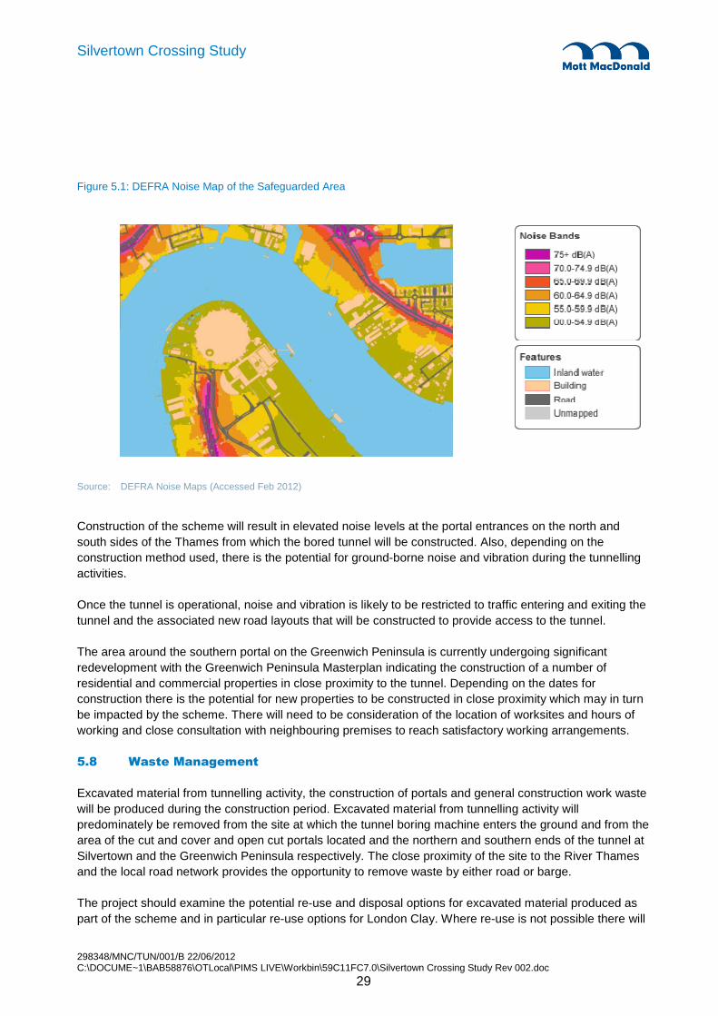
298348/MNC/TUN/001/B 22/06/2012 C:\DOCUME~1\BAB58876\OTLocal\PIMS LIVE\Workbin\59C11FC7.0\Silvertown Crossing Study Rev 002.doc
29
Silvertown Crossing Study
Figure 5.1: DEFRA Noise Map of the Safeguarded Area
Source: DEFRA Noise Maps (Accessed Feb 2012)
Construction of the scheme will result in elevated noise levels at the portal entrances on the north and south sides of the Thames from which the bored tunnel will be constructed. Also, depending on the construction method used, there is the potential for ground-borne noise and vibration during the tunnelling activities.
Once the tunnel is operational, noise and vibration is likely to be restricted to traffic entering and exiting the tunnel and the associated new road layouts that will be constructed to provide access to the tunnel.
The area around the southern portal on the Greenwich Peninsula is currently undergoing significant redevelopment with the Greenwich Peninsula Masterplan indicating the construction of a number of residential and commercial properties in close proximity to the tunnel. Depending on the dates for construction there is the potential for new properties to be constructed in close proximity which may in turn be impacted by the scheme. There will need to be consideration of the location of worksites and hours of working and close consultation with neighbouring premises to reach satisfactory working arrangements.
5.8 Waste Management
Excavated material from tunnelling activity, the construction of portals and general construction work waste will be produced during the construction period. Excavated material from tunnelling activity will predominately be removed from the site at which the tunnel boring machine enters the ground and from the area of the cut and cover and open cut portals located and the northern and southern ends of the tunnel at Silvertown and the Greenwich Peninsula respectively. The close proximity of the site to the River Thames and the local road network provides the opportunity to remove waste by either road or barge.
The project should examine the potential re-use and disposal options for excavated material produced as part of the scheme and in particular re-use options for London Clay. Where re-use is not possible there will

298348/MNC/TUN/001/B 22/06/2012 C:\DOCUME~1\BAB58876\OTLocal\PIMS LIVE\Workbin\59C11FC7.0\Silvertown Crossing Study Rev 002.doc
30
Silvertown Crossing Study
be a requirement to dispose of excavated material, by licensed carriers, to licensed landfill sites and handled in accordance with the Waste Management Regulations.
Site waste management plans will be produced for the scheme (as required in the Site Waste Management Regulations 2008). These will include information regarding the type and quantities of waste to be produced, waste carrier details and plans for the, disposal or re-use of waste and the segregation and control of waste at each site. The assumptions for the quantity and % of contaminated material are contained in the cost estimate sections.
5.9 Water Resources and Flood Protection
5.9.1 Surface Water
There are two main rivers located within the immediate vicinity of the safeguarded area, the River Thames and the River Lea.
The River Thames flows in a southeast ward direction at the location of the development and discharges into the sea approximately 42 kilometres downstream. The Thames is tidal at the proposed development site with a normal tidal height of up to 3.56 metres above ordnance datum (Mean High Water Spring). However, water levels can be significantly higher such as observed on 1 February 1953 when levels in the Thames reached 5.26 metres above ordnance datum following a storm surge in the North Sea.
The Thames has been classified as of moderate ecological status under the Thames River Basin Management Plan - Estuarine. Its chemical status has been recorded as fail, which means that it does not comply with the environmental chemical standards in the Environmental Quality Standards Directive. As the river is tidal at this location, there is a high degree of water mixing and high suspended solids. The highest suspended solids value recorded between 2000 and June 2010 is 551 milligrams per litre (Solid/sus@105) in October 2004 with an average value of 74.5 milligrams per litre (Environment Agency data).
The River Lea flows southwards before it joins the Thames and is located to the west of the Silvertown Portal area of the scheme. The lower reaches of the river are managed under the Thames River Basin Management Plan - Estuarine and have been classified as having moderate ecological status, while the chemical status is classed as fail. Given the nature of the works it is not anticipated that the bored tunnel option will directly impact on any surface watercourses and no works are proposed within the River Thames or the River Lea. Where works are proposed in close proximity to the surface watercourses appropriate mitigation measures, such as those outlined in Environment Agency’s Environmental Good Practice Site Guide and CIRIA guidance 532 Control of water pollution from construction sites: Guidance for consultants and contractors will require to be incorporated into the scheme.
5.9.2 Flood Risk
The scheme is located predominately within Flood Zone 3. However, the site benefits from defences which effectively remove it from the Flood Risk Zone and locate it within the residual risk floodplain.
The River Thames flood protection works, including the Thames Barrier, provides protection in the project area to a safe defence level of 5.23m OD, (e:mail Biggs, Environment Agency to Rock, Mott MacDonald 12/03/2009).

298348/MNC/TUN/001/B 22/06/2012 C:\DOCUME~1\BAB58876\OTLocal\PIMS LIVE\Workbin\59C11FC7.0\Silvertown Crossing Study Rev 002.doc
31
Silvertown Crossing Study
It may be possible to provide localised flood protection by ensuring the road alignment rises to a level of +5.23m at each approach, and that the tunnel portal headwall and walls to the approach ramps are at the same level. In this way flood protection would be assured even if there were a breach of the wider area flood protection. This may be desirable from the point of view of returning the tunnel asset back to service as soon as possible after a flood event. However, the current designs have not accounted for this as the detail of the tie-ins to the adjacent road network would need to be developed first. However the possibility of achieving this will need to be determined in the design of the connecting roads which are outside of the scope of this study. A brief review of the alignment suggests this may be difficult to achieve and a lesser flood protection level may need achieved. If this is considered to be a significant risk the provision of flood gates could be made. However this should be considered as a cost benefit analysis as the cost of installing gates is relatively high and they will have a high maintenance cost throughout the life of the tunnel. Such a study should be carried out at the next stage of scheme development. Currently the provision of flood gates is not intended.
It is noted that the existing Blackwall Tunnels have flood protection gates installed. The intention of these gates is to provide protection to London in the event of a breach of the tunnel linings. The perceived risk arises primarily because of the extremely low ground cover beneath the river in particular with regards to the northbound Blackwall Tunnel. The ground cover to the proposed for the tunnel is more secure and floodgates are not deemed necessary. However, if more detailed design development indicates this to be a risk then protection above the tunnel crown could be provided in the form of river bed stabilising and strengthening ground treatment works. Currently this risk is considered to be small and so no allowance is made.
Where works are undertaken in close proximity to the flood defences along the banks of either the River Thames or the River Lea consent from the Environment Agency for works affecting watercourses and/or flood defences will be required prior to undertaking the works.
Given the nature of the work and the size of the site it is anticipated that a formal flood risk assessment will be undertaken and approved by the Environment Agency.
5.9.3 Groundwater
The River Terrace Gravels below the study area have been classified as a secondary (undifferentiated) aquifer, due to their high permeability but limited extent. The River Terrace Gravels are likely to be hydraulically isolated from the underlying secondary aquifers; the Lambeth Group and Thanet Sand Formation and the principal aquifer, the Chalk Formation by the London Clay. However, as the London Clay is of variable thickness and absent in the southern part of the Greenwich Peninsula, it is possible that there is some degree of connectivity between the alluvial deposits and the underlying aquifer.
The Chalk formation outcrops east of the Thames Barrier downstream of the development site. The eastern side of the study area is within an area of secondary B bedrock aquifer. The secondary B groundwater within the aquifers underlying the London Clay Formation in the study area has been classified as having poor quantitative quality and poor (deteriorating) chemical quality.
There are two groundwater abstractions on the Greenwich side of the scheme as detailed in the table below. These abstractions are located approximately 100m north of the portal.

298348/MNC/TUN/001/B 22/06/2012 C:\DOCUME~1\BAB58876\OTLocal\PIMS LIVE\Workbin\59C11FC7.0\Silvertown Crossing Study Rev 002.doc
32
Silvertown Crossing Study
Table 5.2: Licensed abstractions - Greenwich
Licence No. Operator and/or licence name
Source Daily Rate (m3)
Use Date Issued
28/39/44/0051 Abstraction Point 'A' – Chalk Green Place, Greenwich
Groundwater 3456 Heat Pump April 2009
28/39/44/0051 Abstraction Point 'B' – Chalk Green Place, Greenwich
Groundwater 3456 Heat Pump April 2009
Source: Envirocheck report, Environment Agency data (2010)
There is one abstraction in Newham located approximately 300m north east of the northern portal.
Table 5.3: Licensed abstractions - Newham
Licence No. Operator and/or licence name
Source Daily Rate (m3)
Use Date Issued
Th/037/0054/001 Meadowshire Ltd,
18 Western Gateway, Royal Victoria Dock, London
Groundwater Not supplied
Heat Pump May 2009
The information gathered as part of the London Cable Car project indicated that there not any known abstractions for drinking water.
5.10 Sustainability
The original sustainability objectives as noted below such as biodiversity, landscape and cultural heritage are likely to be less important now that the location of the project has been decided. The following sustainability objectives should however remain in the assessment. Sustain
• Biodiversity - Conserve and enhance, where possible, the protection of existing species and the creation of new habitats.
• Air Quality - Minimise air pollution generation and ensure sensitive receptors are not exposed to unacceptable air pollution levels through avoidance or mitigation measures.
• Noise - Minimise noise generation and ensure sensitive receptors are not exposed to unacceptable noise levels through avoidance or mitigation measures.
• Climate Change - Ensure where possible that low carbon options are taken on board during design/construction and operational phase.
• Transport - Support sustainable population and employment growth by improving transport connectivity and delivering an effective and efficient transport system for goods and people.
• Water - Manage and reduce the risk of flooding associated with the development. Ensure where possible, that ground and surface water quality is conserved and protected.
• Landscape and Open Spaces - Where possible protect and enhance the existing landscape and open spaces.

298348/MNC/TUN/001/B 22/06/2012 C:\DOCUME~1\BAB58876\OTLocal\PIMS LIVE\Workbin\59C11FC7.0\Silvertown Crossing Study Rev 002.doc
33
Silvertown Crossing Study
• Cultural Heritage and Archaeology - Where possible preserve and protect cultural heritage and archaeological assets and ensure that the development compliments the local character.
• Health and Well Being - Improve health and well-being where possible by ensuring that the development does not unduly have a negative impact on the local community – seek to reduce health inequalities.
• Equality and Social Inclusion - Promote equality and social inclusion through the provision of improved transport services and equal access to employment and community services and facilities.
The design as developed to-date contributes in the following respects;
• The vertical alignment is developed to be energy efficient utilising shallow gradients, with a peak of 4% but generally at 2%. The natural sag curve is regenerative in that vehicles naturally coast down the descending gradient while the ascending gradient approaching the roundabouts at either end acts as a natural brake. This energy saving compares favourably with most bridge crossing alignments where the ascending gradient is encountered first. The vertical alignment will also favour change in vehicle propulsion philosophy to electric/hybrid etc.
• Tunnel logistics have been organised, working site location and layout, to allow import and export of materials by barge.
• The tunnel invert may be designed to provide for other utilities thereby maximising the value of the infrastructure asset.
• Designing the alignment to minimise the length of cut and cover tunnel minimises the volume of contaminated arisings likely to be encountered.
298348/MNC/TUN/001/B 22/06/2012 C:\DOCUME~1\BAB58876\OTLocal\PIMS LIVE\Workbin\59C11FC7.0\Silvertown Crossing Study Rev 002.doc
34
Silvertown Crossing Study
6.1 Introduction
This section of the report addresses the fire safety issues associated with the bored tunnel option.
Following significant loss of life in tunnel fires, notably the Mont Blanc, Tauern and St Gotthard tunnel fires in 1999 and 2000, the European Directive 2004/54/EC was introduced in 2004 to define minimum safety requirements for road tunnels across Europe. The Directive is strictly applicable for tunnels longer than 500m located on the Trans European Road Network (TERN route). The Directive was subsequently enacted into UK law by means of the Road Tunnel Safety Regulations 2007 (RTSR). Transport for London considers the Directive as good practice to be followed unless it is not cost effective to do so.
6.2 Consultations with London Fire Brigade
Two meetings have been held with London Fire Brigade (LFB) (on 19/12/2011 and 19/01/2012) to discuss the project and the associated key fire and evacuation issues. The minutes are included in Appendix F . The following points were discussed:
• All dangerous goods vehicles (DGVs) would be prohibited from using the tunnel, corresponding to Category E under the ADR regulations.
• The intention would be to take HGVs away from the Blackwall Tunnel.
• The tunnel would not be allowed to have contra-flow traffic other than during maintenance closures of a single bore during off-peak periods, when traffic may be run in the opposite bore in contra-flow under controlled conditions with speed restrictions imposed as necessary.
• There would be no pedestrians or cyclists.
• The use of cross-passages for intervention is of particular concern to LFB. Their view was that cross-passages should be at 100m intervals unless additional mitigation measures are put in place.
Further discussions with the LFB will be needed with a view to reaching agreement on the principal aspects of the fire safety strategy.
6.3 Worst Case Fire Scenario
The worst case fire scenario should take account of the traffic that is expected to use the tunnel.
The traffic flow information provided in the Network Development and Forecasting Report (May 2010) accounts for cars, LGVs and HGVs. From this, the forecast vehicle distribution comprises 76% cars, 13% LGVs and 11% HGVs.
Assuming that all dangerous goods vehicles (DGVs) will be prohibited from using the tunnel, the worst case scenario would concern an HGV with an easily combustible load. The implications of a relaxation from ADR Category E are discussed in section 6.3.2.
6. Bored Tunnel - Fire Life Safety

298348/MNC/TUN/001/B 22/06/2012 C:\DOCUME~1\BAB58876\OTLocal\PIMS LIVE\Workbin\59C11FC7.0\Silvertown Crossing Study Rev 002.doc
35
Silvertown Crossing Study
The worst case scenario would involve one or more buses/coaches stopped close to the fire, i.e. relatively large numbers of vehicle occupants. In addition, persons with reduced mobility (PRMs) should be expected to be present.
6.3.1 Tunnel Ventilation Strategy
A fundamental issue for fire life safety in the tunnel is the effectiveness of smoke control in the event of a major fire. This concerns the suitability of the tunnel ventilation system.
In an event of fire during normal ‘free flowing’ traffic operations, vehicles ahead of the fire would be able to drive unimpeded out of the tunnel. It is proposed to use a longitudinal ventilation system (e.g. comprising jet fans mounted in pairs spaced along the length of the tunnel) to blow smoke in the direction of traffic movement and thereby ensuring fresh air behind the fire incident to allow safe public egress and fire-fighter access.
However, if a fire occurred during congested traffic operations, there would be vehicles and people ahead of the fire incident. Under these circumstances, a longitudinal ventilation system could not be used because vehicle occupants ahead of the fire would be exposed to smoke. Ideally, traffic congestion should be avoided in the tunnel. At this stage, in agreement with TfL, it has been assumed that a ‘Green Wave’ traffic plan would be implemented using appropriate traffic signals north and south of the river to allow traffic ahead of an incident to drive out of the tunnel without restriction to a designated area. The ‘Green Wave’ traffic plan would be activated automatically upon confirmed detection of a fire and would remain in place until the queue is dispersed.
On the basis that a ‘Green Wave’ traffic plan would be implemented, for the purposes of this study, a build up of traffic behind the fire and traffic driving clear ahead of the fire has been assumed as a realistic scenario.
An effective ‘Green Wave’ traffic plan is crucial to the proposed longitudinal ventilation strategy. The implications of not being able to achieve a ‘Green Wave’ traffic plan would result in having to provide a different ventilation system. To cater for stopped vehicles both ahead of and behind an incident, a smoke extraction system would be needed. This would involve a ceiling extract duct, which would probably require a larger tunnel diameter. It should also be noted that if the design fire size is much greater than 50 MW, then a smoke extraction system would generally be inappropriate because of the greatly increased smoke volumes involved. When extraction is inadequate, even though a significant proportion of smoke may be extracted, the residual smoke can still lead to loss of visibility and tenability.
A longitudinal ventilation system could cater for the largest road tunnel design fires and would offer significant capital and maintenance costs compared to a smoke extraction system along the length of the tunnel.
6.3.2 Implications of allowing dangerous goods
As stated above, it is proposed that all dangerous goods vehicles (DGVs) would be prohibited from using the tunnel, corresponding to Category E under the ADR regulations. This could be relaxed subject to risk analysis for the tunnel. For example, allowing liquid fuel tankers to use the tunnel but prohibiting tankers carrying flammable or toxic gases in bulk, corresponds to Category C under the ADR regulations, which would be the same as for Dartford Crossing.

298348/MNC/TUN/001/B 22/06/2012 C:\DOCUME~1\BAB58876\OTLocal\PIMS LIVE\Workbin\59C11FC7.0\Silvertown Crossing Study Rev 002.doc
36
Silvertown Crossing Study
The passage of petrol and oil tankers through the tunnel would increase the risk of major fires. These would potentially include large pool fires with a peak fire size (peak heat release rate) of 200 MW or more (see Table 6.1). A key mitigation measure for such incidents is an effective drainage system to reduce the size of pools and hence limit the peak fire size. Continuous slot gutter systems are advocated in several European countries, following trials involving continuous and ‘instantaneous’ releases of large liquid volumes and measurements of the resulting pool areas. Consideration would also need to given to increasing the design fire size for the ventilation system.
6.3.3 Cross Passage Spacing
Current practice for new UK road tunnels is to provide cross passages at 100m nominal intervals, in accordance with BD 78/99. From a worldwide perspective, national or international standards are generally used as the starting point for cross passage spacing, with adjustments made sometimes to reflect unusual circumstances or risks. Notably, the US standard NFPA 502 specifies 200m and the EU Directive specifies a minimum spacing of 500m.
Although, compliance with BD 78/99 is not strictly necessary for TfL’s road tunnels, BD 78/99 does represent the UK benchmark in overall terms for the acceptable level of life safety risk.
The implications of increased spacing between cross passages are as follows:
• There may be a perception of increased life safety risk. However, an effective longitudinal ventilation system, in combination with an effective ‘Green Wave’ traffic plan, would negate any actual influence from cross passage spacing. See section 6.5.2 for more details on influence of cross passage spacing.
• Cross passages serve a key intervention function in the event of a fire. The fire brigade would need to have a safe bridgehead from which to fight the fire and this is provided by cross passages.
It should be possible to increase the spacing between cross passages if additional measures are taken in order to achieve an equivalent level of safety. For example, provision of a fixed fire fighting system might compensate for the adverse effects of increased cross passage spacing for fire brigade response.
6.4 Design Fire Size
6.4.1 Range of Vehicle Fire Sizes
The design fire size (peak heat release rate) was used to dimension the tunnel ventilation system and for assessing the life safety consequences of major fires. Information on the range of peak fire sizes for buses and HGVs are available from the recommendations of the European UPTUN research project (Ingason, 2006), given in . It should be noted that this table includes both single and multiple vehicle scenarios.
Table 6.1: Peak fire size recommendations by the UPTUN research project
Peak fire size (MW) Description
10 Small van, 2-3 cars
20 Big van, public bus, multiple vehicles
30 Bus, empty HGV
50 Combustible load on truck
70 HGV load with combustibles (approx 4 tonnes)
100 HGV (average)

298348/MNC/TUN/001/B 22/06/2012 C:\DOCUME~1\BAB58876\OTLocal\PIMS LIVE\Workbin\59C11FC7.0\Silvertown Crossing Study Rev 002.doc
37
Silvertown Crossing Study
Peak fire size (MW) Description
150 HGV with easily combustible load
200 or higher Petrol tanker, multiple HGVs, limited by oxygen
Source: Ingason H. ‘Design fires in tunnels’ (2006)
6.4.2 Summary of practices adopted in different countries
The following table summarises the typical design fire assumptions used in different countries, taken from the PIARC report on ‘Design Fire Characteristics for Road Tunnels’ (2012).
Table 6.2: Design fire sizes adopted in different countries
Country Design fires (MW) Notes
Australia 50 With FFFS (deluge system), for ventilation only
Austria 30 High risk category: 50 MW
France 30 - 200 200 MW when transports of dangerous goods allowed but only applied for longitudinal ventilation
Germany 30 - 100 Depending on length and HGV in tunnel
Greece 100 Longitudinal ventilation
Italy 20 - 200
Japan 30
Netherlands 100 - 200 100 MW if tankers are not allowed, otherwise 200 MW for ventilation system
Norway 20 - 100 Depending on risk class, always longitudinal ventilation
Portugal 10 - 100 Based on traffic type
Russia 50 - 100
Singapore 30 - 200 Depends on vehicle types allowed
Spain ≥ 30
Sweden 100 Longitudinal ventilation
Switzerland 30 Smoke extraction equals 3.3-4 m/s times cross section
UK 30 - 100
USA 30 - 300 300 MW if dangerous goods allowed
Source: PIARC. ‘Design fire characteristics in road tunnels’ (2012)
It is evident from Table 6.2 that:
• Several countries adopt a range of fire sizes depending on the type of vehicle admitted to the tunnel, recognising the possibility of larger fires with HGVs and dangerous goods;
• Countries that only utilise longitudinal ventilation allow for higher design fire sizes. The use of higher fire sizes for longitudinally ventilated tunnels reflects that this mode of ventilation can generally be designed to deal with higher fire sizes at reasonable expense, while transverse ventilation would require very expensive increases in tunnel structure and equipment.
6.4.3 Comparison with selected UK tunnels
The ventilation arrangements at a few road tunnels located on the motorway and trunk road network are outlined in this section, to help illustrate the UK context.

298348/MNC/TUN/001/B 22/06/2012 C:\DOCUME~1\BAB58876\OTLocal\PIMS LIVE\Workbin\59C11FC7.0\Silvertown Crossing Study Rev 002.doc
38
Silvertown Crossing Study
The Holmesdale Tunnel is 650m long and comprises twin bores linked by cross-connections at 100m intervals. The tunnel carries over 120,000 vehicles per day. The normal traffic speed is 70 mph. The tunnel ventilation system comprises Saccardo fan stations at the entry portal of each traffic bore. This system was designed to cater for the following fire sizes:
• 30 MW, with an adverse portal pressure of 30 Pa
• 50 MW, with an adverse portal pressure of 15 Pa
• 100 MW, with an adverse portal pressure of 0 Pa
The Hatfield Tunnel is 1.15 km long and comprises twin bores linked by eight cross passages. Each bore carries three lanes. The tunnel carries approximately 90,000 vehicles per day. The normal speed limit is 70 mph. The tunnel was refurbished in 2011. As part of the works, the jet fan ventilation system has been replaced. The design fire size is 100 MW.
The Dartford West and East Tunnels are approximately 1.43 km long. Each tunnel carries two lanes. The two tunnels carry northbound traffic of approximately 140,000 vehicles per day. The normal speed limit is 50 mph. The tunnel ventilation system uses jet fans for longitudinal smoke control. A peak heat release rate of 100 MW fire has been adopted for the refurbishment planned for 2012.
The Hindhead Tunnel opened to traffic in July 2011. The tunnel is 1.8 km long and comprises twin bores linked by cross passages at intervals of approximately 100m. Each bore carries two lanes. The traffic volume is approximately 35,000 vehicles per day. The normal speed limit is 70 mph. The tunnel ventilation system comprises 20 jet fans mounted in pairs along each bore of the tunnel. The jet fans are fully reversible, with a diameter of approximately 1m. For design purposes, a peak heat release rate of 30 MW fire was adopted. This reflected the recommendation of the UNECE (United Nations Economic Commission for Europe) group of experts in 2001, which addressed safety in road tunnels following the Mont Blanc and Tauern tunnel fires. The use of a smaller design fire size for the Hindhead Tunnel compared to the Holmesdale, Hatfield and Dartford tunnels also reflects to lower traffic levels on the A3; the resulting level of life safety risk from major fires is broadly similar.
Regarding TfL’s road tunnels, the Blackwall Northbound Tunnel refurbishment was designed on the basis of a 100 MW fire.
6.4.4 Recommended Fire Size for Ventilation Design
It is proposed that a fire with a peak fire size of 100 MW is considered for the purposes of sizing the tunnel ventilation system. This would be consistent with current TfL, UK and international practice, noting the prohibition of DGVs.
The nature of conditions in the event of larger fires, corresponding to more extreme HGV fires and multiple vehicle incidents, can be examined as a sensitivity check.
6.4.5 Recommended Structural Fire Resistance
The specification of fire resistance is addressed by reference to standard fire temperature curves. The recommendation of the World Road Association (PIARC) and the International Tunnelling Association (ITA), for an immersed tunnel carrying HGVs and tankers, is for 2 hours fire resistance to the Dutch RWS fire curve. The RWS curve was developed by the Dutch Ministry of Public Works, the Rijkswaterstaat

298348/MNC/TUN/001/B 22/06/2012 C:\DOCUME~1\BAB58876\OTLocal\PIMS LIVE\Workbin\59C11FC7.0\Silvertown Crossing Study Rev 002.doc
39
Silvertown Crossing Study
(RWS) to simulate tankers carrying petrol with a peak heat release rate of 300 MW and lasting for 2 hours. Following this curve (see Figure 6.1), the temperature rapidly exceeds 1200°C and peaks at 1350°C afte r 60 min and then falls gradually to 1200°C after 120 min. For comparison, the ISO 834 curve is used for general building products.
Figure 6.1: Standard fire temperature-time curves
0
200
400
600
800
1000
1200
1400
0 30 60 90 120
Time (min)
Tem
pera
ture
(°C
)
RWS
ISO 834
6.5 CFD Modelling
Computational Fluid Dynamics (CFD) modelling has been undertaken to assess conditions within the tunnel in the event of a fire incident.
The model geometry represents a 600m section of the tunnel (corresponding to the Silvertown end of the southbound tube) with a maximum gradient of 4%. Steep gradients present the worst case scenario for smoke control.
An HGV fire with a peak fire size of 100 MW has been modelled, with ‘time-squared’ growth reaching the peak after 10 minutes. Time-squared fire growth curves are commonly used for fire safety engineering purposes in the UK, for example as given in PD 7974-1 (British Standards, 2003). The fire size is then given by Q = α t2, where Q is the fire size (MW), α is a constant (kW/s2) and t is time (s). For road tunnel applications, it is common practice to refer to a time interval of 5 or 10 minutes for the time taken to reach the peak fire size. For example, the French guidance (CETU, 2003) refers to a ‘standard’ HGV fire growing to 30 MW in 10 minutes.
For longitudinal smoke control, the critical velocity to prevent smoke backlayering is about 2.5 – 3 m/s for fires of order 50 – 100 MW. In line with this, it has been assumed that, upon detection, the tunnel ventilation airflows would increase linearly up to 3 m/s over a period of approximately 5 minutes,reflecting the time taken to energise pairs of jet fans in turn. A serious fire would be detected by the automatic tunnel fire detection system within 1 to 2 minutes (see section 6.6.2 for more details on detection times).
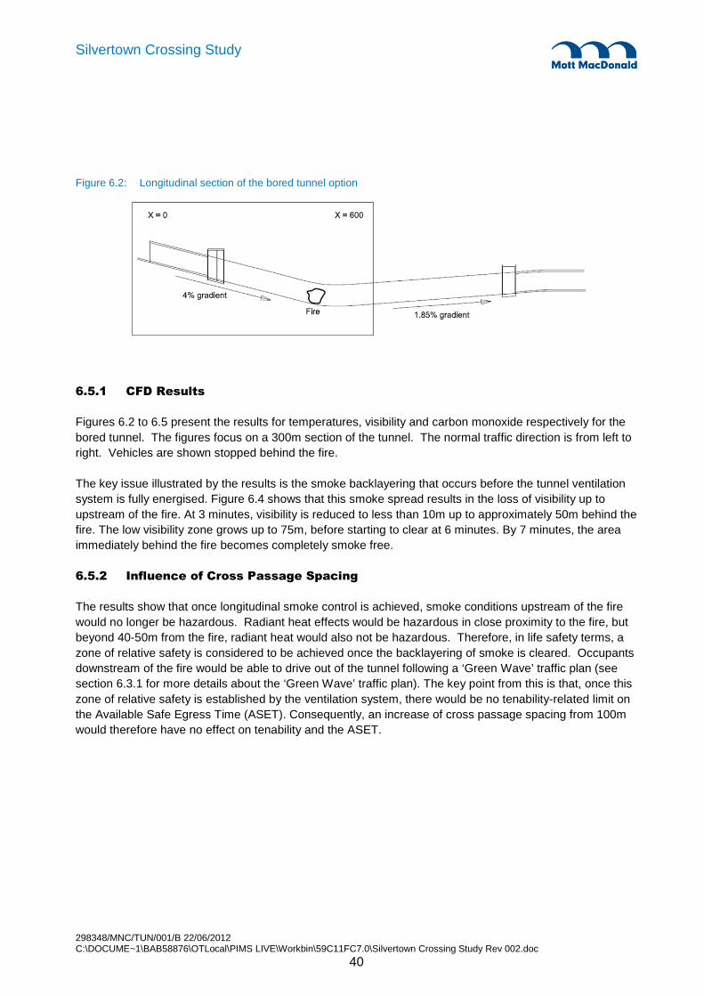
298348/MNC/TUN/001/B 22/06/2012 C:\DOCUME~1\BAB58876\OTLocal\PIMS LIVE\Workbin\59C11FC7.0\Silvertown Crossing Study Rev 002.doc
40
Silvertown Crossing Study
Figure 6.2: Longitudinal section of the bored tunnel option
6.5.1 CFD Results
Figures 6.2 to 6.5 present the results for temperatures, visibility and carbon monoxide respectively for the bored tunnel. The figures focus on a 300m section of the tunnel. The normal traffic direction is from left to right. Vehicles are shown stopped behind the fire.
The key issue illustrated by the results is the smoke backlayering that occurs before the tunnel ventilation system is fully energised. Figure 6.4 shows that this smoke spread results in the loss of visibility up to upstream of the fire. At 3 minutes, visibility is reduced to less than 10m up to approximately 50m behind the fire. The low visibility zone grows up to 75m, before starting to clear at 6 minutes. By 7 minutes, the area immediately behind the fire becomes completely smoke free.
6.5.2 Influence of Cross Passage Spacing
The results show that once longitudinal smoke control is achieved, smoke conditions upstream of the fire would no longer be hazardous. Radiant heat effects would be hazardous in close proximity to the fire, but beyond 40-50m from the fire, radiant heat would also not be hazardous. Therefore, in life safety terms, a zone of relative safety is considered to be achieved once the backlayering of smoke is cleared. Occupants downstream of the fire would be able to drive out of the tunnel following a ‘Green Wave’ traffic plan (see section 6.3.1 for more details about the ‘Green Wave’ traffic plan). The key point from this is that, once this zone of relative safety is established by the ventilation system, there would be no tenability-related limit on the Available Safe Egress Time (ASET). Consequently, an increase of cross passage spacing from 100m would therefore have no effect on tenability and the ASET.

298348/MNC/TUN/001/B 22/06/2012 C:\DOCUME~1\BAB58876\OTLocal\PIMS LIVE\Workbin\59C11FC7.0\Silvertown Crossing Study Rev 002.doc
41
Silvertown Crossing Study
Figure 6.3: Bored Tunnel – Temperatures in vertical section through centre of fire
1 minute
2 minutes
3 minutes
4 minutes
5 minutes
6 minutes
7 minutes
15 minutes

298348/MNC/TUN/001/B 22/06/2012 C:\DOCUME~1\BAB58876\OTLocal\PIMS LIVE\Workbin\59C11FC7.0\Silvertown Crossing Study Rev 002.doc
42
Silvertown Crossing Study
Figure 6.4: Bored Tunnel – Temperatures at 2.0m head height
1 minute
2 minutes
3 minutes
4 minutes
5 minutes
6 minutes
7 minutes
15 minutes

298348/MNC/TUN/001/B 22/06/2012 C:\DOCUME~1\BAB58876\OTLocal\PIMS LIVE\Workbin\59C11FC7.0\Silvertown Crossing Study Rev 002.doc
43
Silvertown Crossing Study
Figure 6.5: Bored Tunnel – Visibility at 2.0m head height
1 minute
2 minutes
3 minutes
4 minutes
5 minutes
6 minutes
7 minutes
15 minutes
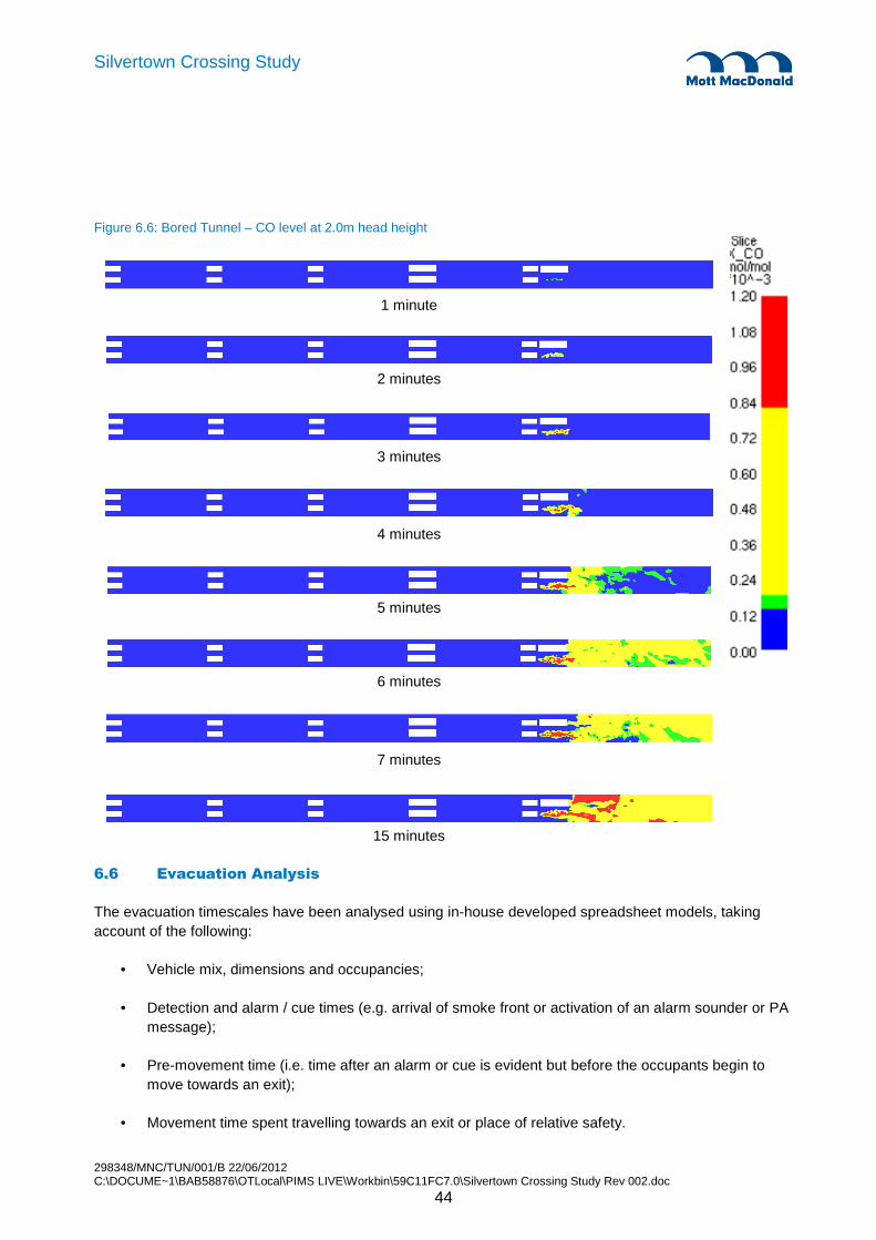
298348/MNC/TUN/001/B 22/06/2012 C:\DOCUME~1\BAB58876\OTLocal\PIMS LIVE\Workbin\59C11FC7.0\Silvertown Crossing Study Rev 002.doc
44
Silvertown Crossing Study
Figure 6.6: Bored Tunnel – CO level at 2.0m head height
1 minute
2 minutes
3 minutes
4 minutes
5 minutes
6 minutes
7 minutes
15 minutes
6.6 Evacuation Analysis
The evacuation timescales have been analysed using in-house developed spreadsheet models, taking account of the following:
• Vehicle mix, dimensions and occupancies;
• Detection and alarm / cue times (e.g. arrival of smoke front or activation of an alarm sounder or PA message);
• Pre-movement time (i.e. time after an alarm or cue is evident but before the occupants begin to move towards an exit);
• Movement time spent travelling towards an exit or place of relative safety.
298348/MNC/TUN/001/B 22/06/2012 C:\DOCUME~1\BAB58876\OTLocal\PIMS LIVE\Workbin\59C11FC7.0\Silvertown Crossing Study Rev 002.doc
45
Silvertown Crossing Study
6.6.1 Vehicle Mix and Occupancy
It is assumed that the traffic comprises 76% cars, 13% LGVs and 11% HGVs. In the absence of specific information, it is assumed that 5% of HGVs are actually buses and coaches. Vehicle occupancy is assumed to be two persons per car, LGV and HGV, and forty persons per bus.
6.6.2 Detection and Alarm Times
Generally, the first indication of an incident will be the detection of one or more stopped vehicles. With an automatic incident detection system (such as a CCTV or radar based system), this would happen almost instantly. An alert would be provided to the operator to investigate.
For tunnels with continuous ‘24/7’ surveillance by operators in a control room, an operator using the CCTV would usually observe an incident within 30 to 60 seconds, depending on the number of tunnels being monitored and the number of cameras. Response could be affected by other events on the road network and therefore relatively slow sometimes.
An automatic fire detection system would detect (and pinpoint) a vehicle fire in the tunnel within 1 to 2 minutes, and possibly faster depending on the technology utilised. Video smoke detection (using the CCTV cameras) would generally provide the fastest response, possibly within 30 seconds. Linear heat detection systems (using a cable along the soffit of the tunnel) are generally slower to respond. Small fires, due to their lower temperatures, will generally take longer to be detected, say within 3-5 minutes.
It is also possible that a tunnel user would raise the alarm by using one of the emergency telephones or fire alarm call-point buttons or by calling from a mobile phone. It is anticipated that when mobile phones are used to report an incident, this may result in emergency services being contacted directly, leaving the tunnel control room out of the communication loop initially.
In general, an alarm would be investigated and confirmed by an operator at the Tunnel Control Centre, and the emergency services notified after a further 1 minute. At this point an evacuation would be initiated using the tunnel PA system and other means.
6.6.3 Pre-Movement Time
The pre-movement time would vary quite widely. Persons close to the incident would be more aware of the situation and would therefore start to move relatively quickly, say within 1-2 minutes.
In contrast, tunnel users in vehicles stopped further away from the fire might not be aware of the hazardous circumstances and, even if they hear a public address (PA) announcement, they may be less inclined to start evacuation promptly. Some drivers may also be reluctant to leave the apparent safety of their vehicles. For such reasons, the pre-movement times of tunnel users away from the immediate vicinity of a fire would probably exceed 5 minutes.
In the case of buses and coaches, it could take an additional 2 to 3 minutes for the last passenger to get off the vehicle.
6.6.4 Movement Time
Tunnel users will be able to evacuate on foot from the incident tunnel via the cross passages, assumed for the present purposes to be spaced at 100m intervals. On that basis, the furthest distance an evacuating
298348/MNC/TUN/001/B 22/06/2012 C:\DOCUME~1\BAB58876\OTLocal\PIMS LIVE\Workbin\59C11FC7.0\Silvertown Crossing Study Rev 002.doc
46
Silvertown Crossing Study
person would need to walk in the incident tunnel in order to reach a place of safety would be 100m. For able-bodied persons, a horizontal walking speed of 1 m/s is assumed. The movement time to reach the first cross passage would therefore be 100m / 60 m/min = 1.6 minutes.
For persons of reduced mobility (PRMs), which includes small children and elderly persons as well as disability-related mobility impairments, “CIBSE Guide E Fire Safety Engineering” [7] suggests that a walking speed of half the speed of an able-bodied person should be assumed, i.e. approximately 0.5 m/s. The movement time to walk 100m would therefore be 100m / 30m/min = 3.3 minutes.
6.6.5 Overall Evacuation Timescales
summarises the key actions and timescales (described in sections 6.6.2 to 6.6.4) in the event of a vehicle fire adjacent to a cross passage (therefore preventing its use for evacuation).. The timescales reflect the range of circumstances and different user groups who may be evacuating in an event of a fire incident. Generally, the majority of the occupants would move quickly.
Table 6.3: Evacuation timescales
Delay for last person to reach cross passage at 100 m behind fire (minutes)
Action Able-bodied PRMs
Detection and alarm 0.5 - 2 0.5 - 2
Alarm investigation and initiation of evacuation 1 1
Pre-movement for persons close to incident 1 – 2 1 - 2
Additional pre-movement time for last bus passenger ≤ 2 ≤ 2
Movement time to reach place of safety ≤ 1.6 ≤ 3.3
Required Safe Egress Time (RSET) ≤ 8.6 ≤ 10.3
6.6.6 STEPS Evacuation Simulation
This simplified approach is supplemented with a pedestrian movement simulation carried out using our in-house developed STEPS software, to illustrate the situation. Key modelling assumptions are summarised below:
• Vehicle mix and occupancy as indicated in section 6.6.1;
• Detection and pre-movement times as given in (using the maximum values in Table 6.3);
• Bus/coach exit rate of 1 person every 3 seconds;
• Walking speed of 0.5 m/s (using the walking speed for PRMs as a conservative assumption).
STEPS is a stochastic model which reflects some of the variability associated with human behaviour.
Any mitigation measures that would be deployed to manage evacuation, such as PA systems, radio re-broadcast systems, tunnel message signs, beacons, sirens, etc would be considered inherent in the assumed pre-movement times. Pre-movement time also reflects factors such as association to other members of a group travelling together and familiarity with the tunnel environment..

298348/MNC/TUN/001/B 22/06/2012 C:\DOCUME~1\BAB58876\OTLocal\PIMS LIVE\Workbin\59C11FC7.0\Silvertown Crossing Study Rev 002.doc
47
Silvertown Crossing Study
The worst case evacuation scenario was assumed to involve a coach, carrying a large number of people, located adjacent to the fire location. The modelling assumptions include consideration of PRMs vacating vehicles and travelling at a reduced speed to reach a cross passage located behind the fire.
Given the stochastic nature of the STEPS program, several simulations are usually carried out in order to obtain an average prediction. In this case, a set of 10 simulations was carried out to obtain the average time taken for evacuees to reach the cross passage located 100m behind the fire. The results are presented in : Figures 6.6 and 6.7 present ‘camera’ and plan views respectively of one of the STEPS simulations.
Table 6.4: Summary of STEPS simulation results –Time to reach a cross passage behind the fire
Run Delay for last person to reach cross passage 100m behind the fire (minutes)
1 10:42
2 10:30
3 10:35
4 10:30
5 10:30
6 10:29
7 10:32
8 10:30
9 10:30
10 10:32
Average 10:32
Figure 6.7: ‘Camera’ view of people evacuating in STEPS simulation
Figure 6.8: Plan view of STEPS simulation
5 minutes

298348/MNC/TUN/001/B 22/06/2012 C:\DOCUME~1\BAB58876\OTLocal\PIMS LIVE\Workbin\59C11FC7.0\Silvertown Crossing Study Rev 002.doc
48
Silvertown Crossing Study
6 minutes
7 minutes
8 minutes
9 minutes
10 minutes
10:3 minutes
In this simulation, people are routed along the walkway rather than using the carriageway. The last person reaches the cross passage after 10.3 minutes from initiation of fire (this includes the 2 minutes detection time, 1 minute investigation time and 2 minutes pre-movement time). The results demonstrate the movement of evacuees along the walkway and into the cross passage without a significant delay in queuing, due to the relatively small number of people involved in a road tunnel evacuation (compared to a typical office building evacuation, for example).
6.7 Fire Brigade Intervention
6.7.1 Alerting the Fire Brigade
As described in section 6.6.2, a fire might be discovered by a member of the public or staff within the tunnel and by their activation of a fire call point the control room will be alerted. The indication of a fire might also be noticed at an early stage by CCTV monitoring of traffic movements or alternatively by the automatic fire detection system. The arrangements for contacting the fire brigade would be from the control room once the nature of the incident has been confirmed.
Cross passage location

298348/MNC/TUN/001/B 22/06/2012 C:\DOCUME~1\BAB58876\OTLocal\PIMS LIVE\Workbin\59C11FC7.0\Silvertown Crossing Study Rev 002.doc
49
Silvertown Crossing Study
It is important that information is transmitted to the fire brigade to identify the location and nature of the incident.
However, when mobile phones are used to report an incident by a member of the public, this may result in emergency services being contacted directly, leaving the tunnel control room out of the communication loop initially.
6.7.2 Fire Brigade Arrival
The closest fire stations to Silvertown Tunnel will be Silvertown fire station on North Woolwich Road, to the north of the river, and East Greenwich fire station on Woolwich Road, to the south of the river. Fire brigade arrival time is assumed to be of the order of 10 minutes to the either end of the tunnel. Evacuation would still be underway at this time.
It is noted that the fire brigade response may not be from one of these fire stations depending on the deployment of their crews at the time.
6.7.3 Dynamic Risk Assessment
The fire officer in charge would initially undertake a dynamic risk assessment to assess the situation and determine the most appropriate course of actions to be undertaken.
The fire officer in charge will communicate with the control room, as well as personally assess the site conditions and will then apply judgement in determining the most appropriate course of action. The decision on how to address the incident with regard to positions of fire appliances and control points would have to be taken quickly.
As the incident develops additional factors could arise, which either require the original decision to be changed or, at least, modified. Decision making may become reactive as the incident develops, events may begin to drive decisions. The situation would be managed through constant monitoring and review of the effectiveness of the incident controls put in place. In this stage of the incident it is vital that communication systems remain operable, together with the command structure to relay information to/from the fire ground to ensure decision making remains firm and effective.
6.7.4 Immediate Response
The response time would depend on the conditions and possible fire spread.
Fire fighters would approach the incident from the non-incident bore via the cross passages. The cross passages would provide safe places for fire fighters to prepare themselves with the necessary protective equipment, including breathing apparatus, and set up their control points for managing the incident response.
The cross passages would not be the only places of relative safety, given that the tunnel environment be tenable behind the fire and zone affected by radiant heat.
6.7.5 Influence of Cross Passage Spacing
Provision of cross passages at 100m intervals would allow for easier fire fighting operations because fire fighters will have shorter distances over which to carry heavy equipment and possibly wear breathing

298348/MNC/TUN/001/B 22/06/2012 C:\DOCUME~1\BAB58876\OTLocal\PIMS LIVE\Workbin\59C11FC7.0\Silvertown Crossing Study Rev 002.doc
50
Silvertown Crossing Study
apparatus (BA). BA sets usually last for a period of 30 minutes. If for instance, a walking speed of 1 m/s (60 m/min) is considered, it would take less than 2 minutes to reach the fire, and allowing for another 2 minutes to return back to the bridgehead, this would allow approximately 25 minutes for fire fighters to carry out fire fighting activities while wearing BA.
If the spacing of cross passages was increased up to 500m, this would potentially allow firefighters only 10 to 15 minutes at the fire. This would make it more difficult for the fire brigade to deal with a major fire. See section 6.3.3 for consideration of other factors influencing the spacing of cross passages.
6.8 Tunnel Facilities
Although the risks of tunnel incidents would be small, a comprehensive range of safety facilities and procedures would need to be put in place in order to mitigate the consequences if serious incidents do occur.
Self-rescue is a key principle for effective life safety, since it is possible that firefighters may not reach the incident until 15 minutes or more after a fire has started. Reflecting this, the design would need to incorporate a range of measures to provide early warning, effective visual and audio communications and clearly identifiable egress routes to help people respond and evacuate quickly when necessary. Attention would also be given to the reliability and continued availability of essential equipment during an incident.
The facilities would include:
• emergency equipment at intervals along both walls of the tunnel;
• traffic surveillance and incident detection systems;
• traffic control systems;
• communications and warning systems;
• emergency escape routes;
• provisions for disabled persons;
• tunnel and cross passage ventilation;
• drainage system;
• structural fire protection; and
• emergency services access and facilities.
6.8.1 Power supplies
Electrical power for the tunnel would be obtained from two independent grid supplies, so that the tunnel would continue to be fully operational even if one supply is lost in an event of a fire. In addition to this, an Uninterruptible Power Supply (UPS) battery system would be provided to enable essential systems to operate for two hours to allow the safe closure of the tunnel. The UPS would provide power for key

298348/MNC/TUN/001/B 22/06/2012 C:\DOCUME~1\BAB58876\OTLocal\PIMS LIVE\Workbin\59C11FC7.0\Silvertown Crossing Study Rev 002.doc
51
Silvertown Crossing Study
systems such as the tunnel emergency lighting, escape route signs and lighting, and the tunnel message system.
6.8.2 Emergency equipment at safety niches and cross passages
An Emergency Point (EP) with equipment for the public to use would be provided at intervals along the tunnel including at each cross passage. Each EP would contain an emergency telephone, a fire alarm call-point button and two portable fire extinguishers. It is good practice to provide a fire alarm call point as they are familiar to everyone from their universal use throughout the built environment and provide a convenient, direct and reliable method of raising a fire alarm.
6.8.3 Traffic surveillance and incident detection systems
Closed Circuit Television (CCTV) cameras would provide full coverage of both bores and all cross passages. This would allow an operator at the tunnel control centre to monitor the whole tunnel. The operator would be able to mobilise the emergency services to the tunnel and direct them to the incident location.
An automatic incident detection system would be installed. The system would be capable of detecting the passage of individual vehicles and would be configured to provide detection of a single stopped vehicle as well as stationary queues of traffic in and on the immediate approaches to the tunnel. Currently both video-based and radar-based technologies are in use.
Automatic fire detection would be provided throughout the tunnel. Current technologies include video-based systems or linear heat detection systems comprising a cable running along the soffit of each tube.
6.8.4 Traffic control systems
A traffic control system would be necessary in an emergency in order to advise approaching drivers of hazards ahead and for restricting use of a lane or carriageway to allow planned maintenance activities to take place safely in the tunnel or on its immediate approaches.
A combination of the following types of automatic variable message signs and signals would be appropriate in the tunnel and at the portals:
• Tunnel message signs with the capability of displaying short text messages would be located above the carriageway at the portals and along each tube of the tunnel, at approximately 200m intervals.
• Tunnel Lane Control Signals would be suspended above each lane throughout each bore of the tunnel, at approximately 200m intervals. They would display an internally illuminated green arrow or red cross. The signals would be used to reinforce any signal settings on the tunnel approaches to warn drivers of hazards that require a lane or carriageway closure.
• Matrix signals would be installed at the tunnel portals above each lane to indicate advisory reduced maximum speed limits, lane restrictions, complete carriageway (tunnel bore) closure, and other events.
• Traffic signals and barriers would also be installed on the approaches to the tunnel.

298348/MNC/TUN/001/B 22/06/2012 C:\DOCUME~1\BAB58876\OTLocal\PIMS LIVE\Workbin\59C11FC7.0\Silvertown Crossing Study Rev 002.doc
52
Silvertown Crossing Study
The remote control of all automatic variable message signs and signals would be through the setting of pre-configured sign plans using the traffic control system.
The plans would provide a traffic management response to credible hazards that could arise in the operation of the tunnel, as well as for establishing traffic management required for routine planned maintenance of the tunnel.
6.8.5 Communications and warning systems
The tunnel would be fitted with a leaky-feeder or aerial system to enable the use of mobile phones, a radio re-broadcast system and radio relay for the emergency services inside the tunnel. This would allow anyone to request help using their mobile phone, without having to leave their vehicle.
Reflecting the importance of self-help and self-rescue, safety messages would be provided for the public in the event of vehicle breakdowns or accidents, traffic congestion or a hazardous event such as a fire. The design should incorporate both audio and visual messaging systems for this purpose:
• A radio re-broadcast system would enable audio messages to be given to road users in the tunnel, by interrupting the most commonly used public broadcast radio frequencies. Clearly, this would only be effective if drivers have switched on their radios. There would be signs on the approaches to the tunnel to advise drivers to do this.
• A Public Address (PA) system would be installed throughout each bore and cross passages to provide audio messages directed at people on foot or in stopped vehicles.
• Fire Action signs would be installed at intervals along the walls of each tube and in the cross passages. These signs would show a combination of standard graphical symbols and simple text messages to advise or warn tunnel users, complementing the PA messages.
6.8.6 Emergency escape routes
In the event of an emergency in one bore, people would be able to evacuate into the non-incident bore via the cross passages. Once in the non-incident bore, people would be directed to one of the portals.
A pair of emergency exit (‘running man’) signs would be provided at 25m intervals along both walls of each tube at a height of 1.2m above the verge. The signs would indicate the nearest available emergency exit (cross passage or portal) in each direction. A low level escape route wayfinding system would be provided along both walls of each tube. These signs and wayfinding system would be internally illuminated, or possibly implemented as photoluminescent signs and strips.
Prominent illuminated emergency exit (‘running man’) signs would be provided above the entries to each cross passage.
Entry to each end of a cross passage would be through a pair of emergency double swing doors with self closers set in a bulkhead separating the cross passage from the adjacent bore of the tunnel. Each bulkhead with door would provide 2 hours fire resistance.
In order to avoid possible risk of evacuees stepping straight into the non-incident tube where there may still be live traffic, consideration will be given to a combination of the following mitigation measures:

298348/MNC/TUN/001/B 22/06/2012 C:\DOCUME~1\BAB58876\OTLocal\PIMS LIVE\Workbin\59C11FC7.0\Silvertown Crossing Study Rev 002.doc
53
Silvertown Crossing Study
• In some road tunnels, e.g. the Holmesdale tunnel, the cross passage doors are locked until it is safe to enter the non-incident tube.
• Alternatively, the cross passage doors can be set back from the carriageway. For example, in the Hindhead tunnel, the cross passage bulkhead and doorset are set back 3m from the face of the tunnel wall. This allows people more time to adjust to the ‘new’ situation in the non-incident tube (i.e. to see and hear any live traffic) before reaching the edge of the carriageway.
• A further alternative, as adopted at the Dublin Port Tunnel, is to provide pedestrian guard rails in front of the cross passage entrances.
• Measures would also be provided to warn the public of the risk of moving traffic by deploying internally illuminated warning signs inside the cross passages, directly above each cross passage doorset. In addition, the cross passage doors would have vision panels, through which people would be able to see whether traffic was still moving in the non-incident bore.
• Although the cross passages would not be used as refuges, it might be appropriate for people to pause in the cross passages briefly (for a couple of minutes) in the event that there is still traffic moving in the non-incident bore..
6.8.7 Provisions for disabled persons
Both audio and visual means of communications and warning would be provided. For instance, moving traffic would be served by radio re-broadcast and tunnel message signs, while the PA system and Fire Action signs would cater for incidents. Mobile phones would function throughout the tunnel bores and allow a disabled person to call for assistance from their vehicle. Consideration would be given to provision of emergency telephones with text displays and keypads to enable motorists with hearing or speech impairments to obtain assistance, however their usefulness should be re-confirmed given the widespread use of mobile phones.
Access to the cross passages would benefit from the 1.2m wide verges on both sides of the carriageways and dropped kerbs at the location of each cross passage.
Arrangements would be put in place to ensure that the cross passage doors can be opened easily without undue effort, although in reality it is highly likely that assistance would be available from other members of the public in the tunnel.
6.8.8 Tunnel and cross passage ventilation
The purpose of the tunnel ventilation system would be to control the air quality within the tunnel during normal traffic operations and the movement of smoke in the event of a fire.
The tunnel ventilation system would probably need to be operated for pollution control only during periods of traffic congestion. Under normal traffic conditions with freely flowing traffic, the ‘piston effect’ generated by traffic movement would ensure that there is a significant airflow in the direction of traffic movement, which would keep pollution concentrations below the relevant air quality criteria.
Should a fire incident occur during normal traffic operations with uni-directional traffic in each bore of the tunnel, the tunnel ventilation system would be used to blow smoke in the direction of traffic movement. This would ensure fresh air upwind of the fire site to allow safe public egress and firefighter access. In
298348/MNC/TUN/001/B 22/06/2012 C:\DOCUME~1\BAB58876\OTLocal\PIMS LIVE\Workbin\59C11FC7.0\Silvertown Crossing Study Rev 002.doc
54
Silvertown Crossing Study
terms of ventilation capacity, more jet fans are needed for smoke control than for pollution control. Provided the ventilation airflow velocity is strong enough, the hot smoke would be prevented from spreading upwind of the fire.
The cross passages would be equipped with suitable ventilation provisions to cater for both normal operations and fire situations.
The ventilation system would be controlled automatically in response to appropriate pollution sensors and the automatic fire detection system provided throughout the tunnel.
6.8.9 Drainage system
The drainage system would play an important role in the event of a major spillage of flammable liquid, since it would have a direct impact on the surface area of the pool of flammable liquid that could be ignited. This would be key if bulk liquid fuel tankers were allowed (ADR category C) but less critical if all DGVs were prohibited (ADR category E). As described in section 6.3.2, continuous slot gutter or kerb entry systems are commonly adopted for this purpose in tunnels in countries such as France. The connections to carrier drains would be equipped with flame traps to prevent fire propagation. The carrier drains would discharge into a sump with pumping facilities. The low point sump in the tunnel would be protected by an automatic inert-foam suppression system to mitigate the risk of an explosion in the confined tunnel environment. The main impounding sump would be located outside of the tunnel at an appropriate distance from the nearest building and would be vented naturally to the atmosphere. The contents of the impounding sump would be pumped as required to road tankers.
6.8.10 Structural fire protection
The structure of the tunnel itself would be designed with passive fire protection to withstand a severe fire without catastrophic consequences, such as a local collapse. For this purpose, the design would assume a fire resistance corresponding to the RWS time-temperature curve for 2 hours. Following this curve, the temperature rises rapidly to over 1000ºC, peaks at 1350ºC and maintains this for two hours. It is anticipated that the passive fire protection of the tunnel lining would be achieved by using a concrete mix with polypropylene fibres.
In addition to the asset protection benefits, this would potentially help to protect tunnel users and fire fighters during an incident, by maintaining the integrity of escape and intervention routes.
6.8.11 Fire suppression system
Fire suppression systems, of the water mist type, have recently been adopted in the tunnels at the Tyne and Dartford crossings. A fixed fire suppression system could likewise be provided in the Silvertown Tunnel. The main benefits of a fire suppression system would be:
• Control of fire growth and fire spread between vehicles;
• Property protection by reducing the severity of a fire, thereby preventing damage and long term disruption of traffic operations; and
• Fires would be controlled until firefighters arrive and make it easier and safer for them to approach and extinguish the fire.
298348/MNC/TUN/001/B 22/06/2012 C:\DOCUME~1\BAB58876\OTLocal\PIMS LIVE\Workbin\59C11FC7.0\Silvertown Crossing Study Rev 002.doc
55
Silvertown Crossing Study
Although, a fire suppression system would provide a perception of enhanced life safety, given the comprehensive range of fire safety measures already adopted in modern road tunnels, the additional benefits are generally modest for the safety of tunnel users. For the Silvertown tunnel, assuming an effective ‘Green Wave’ traffic plan, tunnel users would be protected by the longitudinal smoke control system and other safety measures.
Given the potential challenges for the fire brigade in tackling major tunnel fires, a fire suppression system could be considered as a compensatory measure to balance the risks of increased cross passage spacing.
A decision to install such a system should be based on an assessment of the risks and of the costs and benefits for this specific tunnel, in accordance with the recommendations of PIARC.
6.8.12 Emergency services access and facilities
BD 78/99 specifies fire brigade control panels at the portals, to allow the fire brigade to monitor events in the tunnel and control key systems. For example, the Hindhead Tunnel has such panels installed in the tunnel services buildings at the portals. The panels give an indication of the fire status in each zone. CCTV monitors allow the fire brigade to look at any location along the bores or in any cross passage. The panels also provide the fire brigade with the capability to change the ventilation mode using simple pre-defined options and to maximise the lighting levels in the tunnel. For the Silvertown Tunnel, given the availability of the facilities at LSTOC, there may be less benefit in having these panels. The requirements should be confirmed with LFB.
Each bore would be equipped with a pressurised fire main, with hydrant connections for up to four hoses at each cross passage entry zone. A storage tank would be provided at one of the portals with a water capacity sufficient for 60 minutes of fire fighting, to be agreed with LFB.
6.9 Key Issues
Given the proposed 100 MW design fire size and 4% gradient, the normal ventilation response following initiation of a fire incident would allow smoke backlayering over vehicles stopped behind the fire incident. This would result in a temporary loss of visibility immediately behind the fire up to about 75m and for a period of approximately 7 minutes, potentially making conditions difficult for people to evacuate.
The provision of effective low level lighting and a directional sound beacon system would be important mitigation measures.
In addition, consideration could be given to providing a fixed fire suppression system. Such a system would have to be activated rapidly in order to obtain any benefit for evacuation (see section 6.8.11 for more details on fire suppression system). However, once the ventilation system has achieved longitudinal smoke control, there would be tenable conditions behind the fire.

298348/MNC/TUN/001/B 22/06/2012 C:\DOCUME~1\BAB58876\OTLocal\PIMS LIVE\Workbin\59C11FC7.0\Silvertown Crossing Study Rev 002.doc
56
Silvertown Crossing Study
7.1 Running Tunnels
The ground conditions are challenging comprising mixed geology in the tunnel face including Lambeth beds, London clay and overlying River Terrace Deposits etc. This geology has been successfully mined in the past notably the Jubilee Line Extension which runs close by and the Blackwall and Dartford tunnels also across the Thames. The proposed tunnels at 12.1m outside diameter are larger than previously attempted across the Thames. The Dartford East tunnel has an excavated diameter 10.3m. The proposed outside diameter of 12.1m is large but there is a growing body of similar or larger diameter tunnels in soft ground e.g. the 4th tube Elbe Tunnel in Hamburg (13.75m OD), the Dublin Port Tunnel (11.77m OD) and the Miami Port tunnels about to start construction (12.8m OD).
The proposed tunnels are shallow compared with the majority of tunnels. This has been noted in the Tunnel Design Criteria section but it is also significant in TBM selection and specification as it reduces the range of face pressures within which the TBM can be operated safely and efficiently.
TBM technology has progressed rapidly in recent years and it is now the case that TBM technology is available to overcome most ground conditions including mixed ground conditions. In this respect the Silvertown Crossing tunnels while challenging are not extreme.
7.2 Tunnel Boring Machine (TBM) Selection
The choice of tunnel boring machine is dictated by the nature of the ground to be excavated. The vertical gradient and plan alignment constraints are such that there is negligible freedom to choose the tunnelling medium. While a project specific site investigation remains to be carried out, nevertheless the geology of the area is well known and understood due to extensive tunnelling and civil engineering works effected in the immediate area.
The bored tunnel face will be mixed throughout the length of the drive encountering the geological succession of alluvium, terrace gravels, London Clay, Lambeth beds and Thanet beds. The River Terrace deposits are likely to be water-bearing and there is a likelihood of water-bearing sand and gravel lenses or channels in the Lambeth beds. In the building of the Jubilee Line Extension tunnels in this area, it is worthy of note that EPB tunnelling machines were employed and tunnelling from North Greenwich to Canary Wharf was executed in closed mode and with difficulty.
The mixed ground conditions, the likelihood of encountering water bearing strata beneath the river, and the experience on the Jubilee Line Extension indicate that an EPB type machine could be successfully employed. However, the nearby DLR extension to Lewisham was constructed using a slurry machine in similar ground, albeit slightly lower in the geological succession than the proposed Silvertown crossing, shortly after the construction of the Jubilee Line. It is suggested that although this report will reach a reasoned conclusion on the choice of tunnelling machine, the choice should be re-examined as further specific site investigation information is obtained.
7. Bored Tunnel - Constructability
298348/MNC/TUN/001/B 22/06/2012 C:\DOCUME~1\BAB58876\OTLocal\PIMS LIVE\Workbin\59C11FC7.0\Silvertown Crossing Study Rev 002.doc
57
Silvertown Crossing Study
7.2.1 Slurry TBM
Slurry TBMs support the tunnel face using a slurry (usually a bentonite slurry) pumped into the cutting chamber of the machine ahead of a closed bulkhead. Spoil is transported away from the TBM by pumping via the return slurry line and the spoil is separated from the slurry using a separation plant at the surface. The slurry contains platelets which lock in the interstices of a permeable ground and enable the slurry under pressure to form an impermeable cake at the excavated face of the permeable ground. This restricts and prevents further passage of slurry into the surrounding ground and therefore enables the slurry pressure to balance the surrounding ground pressure.
There is a large source of incoming slurry so any failure of the process will lead to a loss of slurry and a loss of face support. This is a particular risk if major voids are anticipated (i.e. solution features – but not likely to be relevant to this project or man made excavations or conduits) or if there is a short path to the surface whether that is the ground surface or the river bed. Control of face pressure becomes very critical in low cover situations such as Silvertown and any over pressurisation of the TBM face will lead to a high risk of loss of slurry and hence loss of pressure and loss of face support.
The River Terrace deposits are particularly suitable for the use of a slurry TBM but the London Clay and other materials with low permeability are not suited to the use of a slurry TBM. The slurry’s ability to block the interstices of an open material are of no benefit in such ground and the fine particle size makes separation of the spoil from the slurry very difficult.
7.2.2 EPBM
EPB TBMs mobilise the excavated spoil and use the resulting fluidised spoil to provide support to the excavated face. The excavated spoil is retained ahead of a bulkhead on the machine and removal of spoil is via an enclosed Archimedean screw. The screw discharges spoil at atmospheric pressure so there needs to be a pressure gradient along the screw from the face to the open end of the screw. There is a discharge gate which can be controlled from open to fully closed which enables the rate of spoil removal to be controlled. The advance rate of the TBM determines the rate of excavation of spoil and therefore by controlling the discharge from the screw the face pressure can be maintained.
The EPB machine requires the spoil in the screw to act as a plug with a pressure drop along the screw. Open grained materials require a long screw and assistance of fillers injected into the cutterhead to enable face pressure to be maintained.
Open grained materials, particularly in the crown of the excavation are difficult to control. It is very difficult to maintain full face pressure at the top of the face using earth pressure. Often air or conditioning foam will be used to help with spoil mixing and the result is that the ground support at the top of the face comes from, air, foam or liquid and it is possible that material above the cutter head will be dislodged by the cutting action due to inadequate support. Open grained materials at the crown of the tunnel can therefore be a problem.
The River Terrace Deposits are not a uniform open grained gravel so the problem of maintaining the stability at the top of the face and maintaining pressure through the face is not likely to be a major problem. For the majority of the tunnel drive where Terrace Deposits are present they are only present in part of the face, and the clay that forms the remainder of the face will be sufficient to ensure that a plug is formed in the screw.
298348/MNC/TUN/001/B 22/06/2012 C:\DOCUME~1\BAB58876\OTLocal\PIMS LIVE\Workbin\59C11FC7.0\Silvertown Crossing Study Rev 002.doc
58
Silvertown Crossing Study
7.2.3 TBM Choice
The most critical section of the tunnel drives is the section under the river. On the land the infrastructure that is above the line of the tunnels is not especially sensitive to settlement. The prime objective is therefore the selection of the right TBM for the tunnel drive under the river. The predominance of London Clay and the Lambeth beds is well suited to an EPB TBM and therefore dominates the selection decision even though a slurry TBM is more suited to the very beginning and end of each drive.
There are convertible machines, but for these short drives they are not a realistic option as there needs to be duplication of the spoil handling infrastructure. The choice of an EPB machine simplifies spoil handling on the surface and avoids the need for a tunnel spoil separation plant. This should not and does not dominate decision making but it is a significant disadvantage of a slurry machine.
It is suggested the choice of tunnelling machine should be re-examined as further specific site investigation information is obtained.
7.2.4 TBM Features
The TBM will need a high torque in order to work in London Clay in EPB mode. It will need to have facilities to introduce foam and water into the cutting area to condition the clay so that it will behave as a quasi fluid and provide support to the excavated face.
The TBM will need to be able to deal with the potential hard calcrete or limestone bands in the lower mottled beds of the Lambeth group. Irrespective of any pre-prepared intervention locations it will be necessary for the TBM to be equipped to drill angled holes ahead of the face in order to carry out ground treatment ahead of the face in the event of it being necessary to inspect the head and carry out work for repairs or maintenance. There is also a considerable risk of finding timber or steel obstructions on the line of the river wall and elsewhere on land and to deal with these will require unplanned interventions and therefore the ability to carry out ground treatment from the TBM.
In order to carry out interventions, planned or unplanned, it would be necessary to be able to maintain face pressure whilst the spoil is removed from the face. This will require compressed air and therefore airlocks on the TBM and decompression facilities on the surface. With this size of TBM there are likely to be parallel airlocks to allow crews to enter and leave the face at the same time.
7.3 Cut and Cover Tunnels
The bored tunnel approaches comprise open cut ramp and cut and cover tunnels at either end of the bored tunnels. The side walls will be constructed as diaphragm walls or secant piled walls. Diaphragm walls will generally be the solution except for areas where there is a probability of obstructions beneath guide wall level (1.5 to 2m). Secant piles can be constructed in areas of obstructions using a high torque rig with the casing coring through the obstruction.
The cut and cover box depths vary but at their shallowest they are approximately 10m deep. The temporary lateral ground loads during construction will be considerable. It is generally assumed that all boxes will be constructed bottom up but some may be constructed top down, but there will be sections which need to be left open to facilitate TBM operations and these will of necessity be constructed bottom up to allow craneage access during tunnelling. Temporary steel props and/or ground anchors will be needed.

298348/MNC/TUN/001/B 22/06/2012 C:\DOCUME~1\BAB58876\OTLocal\PIMS LIVE\Workbin\59C11FC7.0\Silvertown Crossing Study Rev 002.doc
59
Silvertown Crossing Study
Diaphragm walls will not provide a guaranteed water tight structure. Secant pile walls will only need the soft piles to penetrate the London clay but they will not provide a guaranteed water tight structure. Both methods will require an internal drainage system and cladding to be installed after the box is structurally complete.
Construction of the cut and cover tunnels beneath the DLR will need particular attention. The headroom is nominally about 5m which is not likely to be sufficient for a secant piling rig of sufficient torque capacity or sufficient for a low height D-wall rig. It should be possible to do some limited ground lowering without getting down below the water table and then establishing a piling platform at a lower level to generate sufficient clearance. It is anticipated that a solution can be developed in this area that will have not detrimental impact to the existing DLR structures. The final design and the construction methods will need to be approved by DLR through an AIP process.
7.4 Retained Cut Ramps
The open cut ramps will also comprise diaphragm wall retaining walls and reinforced cast in situ concrete floor slabs. Subject to clearing near surface obstructions during guide trench construction the diaphragm walls should be relatively straightforward for the ramps.
7.5 TBM Drive Strategy
The TBM drive strategy is determined by a number of factors. The principal factors are:-
• Suitability of site to service tunnelling operations.
• Suitability of site for building a TBM.
• Suitability of access to site for heavy loads for TBM assembly
The north side of the river appears to be the most suitable site for servicing the TBM drive. It has most space, it can readily be serviced by barges delivering segments or by road delivery of segments, it can readily be used for spoil removal by ship but the disadvantage is that it has the DLR viaduct. The DLR restrictions can be managed and the Silvertown site is therefore the preferred site to support tunnelling.
The length of the project is not sufficient to justify the capital costs of two TBMs in order to achieve a programme saving, therefore the drive strategy needs to consider the recovery and re-launch of the TBM as well as the initial drive.
Erecting or dismantling a TBM for reuse is a major operation. It is theoretically possible to lift the whole of a TBM (i.e. head, tailskin containing erector and motors) but this is a very large lift and for a 12.5 metre diameter TBM the preference will be to build the TBM in situ on a cradle on a backward projection of the tunnel alignment. This still requires major craneage as the TBM head is a major lift. It also requires working space and lifting zones around the launch location.
The Silvertown site is not ideal but TBM erection is possible in a suitably deepened section of the cut and cover box which will be designed so that in the temporary situation, it is stable without its roof.
After the initial drive there are two possibilities. Dismantle the TBM at Greenwich and transport it in components across the river and repeat the build and launch process from the north side or rotate the TBM at Greenwich and drive it back under the river from Greenwich to Silvertown. If the latter option is taken

298348/MNC/TUN/001/B 22/06/2012 C:\DOCUME~1\BAB58876\OTLocal\PIMS LIVE\Workbin\59C11FC7.0\Silvertown Crossing Study Rev 002.doc
60
Silvertown Crossing Study
there is a further decision to be made as the second drive can be supported by a site infrastructure at Greenwich or can be serviced from Silvertown via the first tunnel.
Rotating the TBM and its back up at Greenwich is not a major operation in terms of craneage. The TBM can be rotated and moved using jacks and skids by specialist contractors and the backup is relatively light and can be pulled out of the first tunnel, lifted by crane and reinstalled behind the TBM.
Setting up the infrastructure to supply segments and handle spoil at Greenwich can be avoided and by using the first tunnel to service the second, the Silvertown infrastructure can be used to service the second drive. This doubles the conveyor length and the segment haulage length, but in tunnelling terms these are short tunnel drives and those costs whilst significant will not offset the additional tunnel support infrastructure cost or offset the programme benefit of turning the TBM round rather than dismantling it, transporting it and rebuilding it.
At both portals extra depth of the cut and cover box is required at both ends for all options and although the strategy options require different box configuration details the total additional work content will be similar.
The restrictions of the DLR and the existence of the old dock passage effectively define the TBM launch position. To avoid driving the TBM though the old dock passage, it has to commence south east of the dock passage and therefore south east of the DLR and the TBM has to be erected close to the DLR and close to or under the shadow of the cable car.
Theoretically the TBM could be built in the cut and cover box north-west of the DLR and pushed down the ramp. This would mean deepening the ramp, leaving the roof off the area to be transitted by the TBM and constructing the whole of the cut and cover box (less roof) prior to the arrival of the TBM. These are all possible but have a major effect on cost or programme or both. It does not eliminate the need to work close to the DLR, but it does reduce the proximity of some major lifting operations. The identified launch location does require heavy lifting of the TBM components close to the DLR but does not require the crane to face the DLR or to operate with the counterweight at the rear of the crane facing the DLR. The non preferred location northwest of the DLR is bounded on one side by the cut and cover box and to the rear by the DLR.
It should be noted that there is a difficulty in launching a TBM on a curve. In any launch situation it is necessary to get to a position where the head of the TBM is in the ground and rings are built and grouted behind the TBM and provide the resistance to the forward thrust of the TBM. This is difficult and is usually achieved using a thrust frame behind the TBM so that the necessary reaction can be provided by the thrust frame. The exit end of the launch box is generally prepared to receive the TBM and to enable a seal to be made around the body of the machine to enable face pressure to be created and maintained. The downward gradient helps slightly but the curvature does not. Steering the TBM requires out of balance forces on the built lining in order to push the outside of the TBM round the outside of the curve and without a substantial number of rings built the necessary out of balance force cannot be achieved. There are solutions. The alignment may need to be adjusted locally but if that is not possible then a solution is to form an underground launch chamber by open face excavation before the TBM is built and to push the machine into the launch chamber without the need for excavation, but using the erector to build rings and using the facilities of the machine to grout those rings to secure them in the launch chamber. The length of the launch chamber would need to be sufficient to enable several rings to be built and grouted before it was necessary for the TBM to begin cutting ground. The cost of this launch chamber has not been included in the base scheme.
Another adverse effect of the curvature is that it dictates the sequence of TBM drives. The EPB machine requires a conveyor. The conveyor needs to extend as the TBM advances. This is normally done using a
298348/MNC/TUN/001/B 22/06/2012 C:\DOCUME~1\BAB58876\OTLocal\PIMS LIVE\Workbin\59C11FC7.0\Silvertown Crossing Study Rev 002.doc
61
Silvertown Crossing Study
cassette which contains multiple returns of the belt. As the TBM is advanced the internal mechanism of the cassette allows each of the returns to shorten to create the additional belt length in the tunnel. When there is no further surplus belt in the cassette, the conveyor belt is cut and a new length of belt is installed in the cassette and joined into the belt. This cassette must continue in a straight line extension of the alignment of the belt on the tunnel wall. This ultimately dictates the choice of the Northbound Tunnel driven southwards as the first drive. It also works for the Southbound tunnel driven northwards. Alternative belt configurations are possible at an additional cost but the chosen drive strategy is the only one that avoids the need for more expensive alternatives.
7.6 TBM Delivery
TBM delivery is likely to be by sea to an East Coast Port and then by road to the Silvertown site. Although the majority of the vehicle movements will be standard articulated lorries and trailers, there will be some special heavy loads for the TBM cutter head. This will be designed to be shipped in segmental form and assembled to form the 12.5m dia. head on site. The road network should be capable of accepting the loads as a nearby site on the Limmo Peninsular will have received similar heavy loads. On site the TBM will need to pass beneath the DLR viaduct. There appears to be 5m headroom. That should be adequate without the need to lower the ground under the viaduct, but that is a contingency. The TBM strategy outlined above does not require TBM delivery or removal via Greenwich. Removal will be the reverse of delivery whether items have a residual value or are removed as scrap from Silvertown.
An alternative approach that could be taken is to bring the TBM to site by river transport. This would require suitable craneage to be established at the quayside for unloading and plant and equipment to transfer the TBM components to the launch shaft.
7.7 TBM Build and Erection
The TBM will be erected in a launch box. This is a specially deepened section of the cut and cover box with the roof omitted. The backup can be installed in a variety of ways. It can be built with the back gantries built first in the launch box and each one pushed back up the cut and cover box to allow the next to be built and when all the backup is built the TBM itself is built in the Launch Box. It can be built in the cut and cover with the roof omitted or it can be built in stages as the TBM is launched initially without the backup with backup gantries added one at a time as the TBM and gantries clear the launch chamber. The optimum choice will become apparent. The important thing is that there are options.
The TBM will be erected on a cradle, either steel or concrete with twin steel sliding surfaces. Behind the TBM there will be a thrust frame to receive the reaction from the TBM through its thrust rams and probably through some temporary rings as the TBM is launched. The end wall of the box will need to have been pre-prepared to receive the TBM. All reinforced concrete will have been removed and a circular opening created in the end wall of the launch box. Within the opening there will be a seal that will form a pressure resistant seal all round the main body of the TBM and the tailskin of the machine as it progresses. The TBM will push forward until the head is through the seal in the box wall and before the TBM reaches the temporary ground support, the head of the TBM will be charged and pressurised (probably with a thick bentonite slurry). Only then will it be able to cut the ground and provide support to the ground. Noting that the ground appears to be River Terrace Deposits, the initial length of the drive may require ground treatment (jet grouting) from the surface.
It is likely that the TBM will not be launched with its full backup. There may therefore need to be stoppages to connect the backup during the first stages of the TBM drive and prior to the full backup being connected,
298348/MNC/TUN/001/B 22/06/2012 C:\DOCUME~1\BAB58876\OTLocal\PIMS LIVE\Workbin\59C11FC7.0\Silvertown Crossing Study Rev 002.doc
62
Silvertown Crossing Study
there may need to be temporary arrangements to allow spoil removal, segment delivery and provision of services.
7.8 TBM Reversal and Removal
At Greenwich it is proposed to turn the TBM through 180degrees and re-launch it back to Silvertown. The TBM will break out of the tunnel though a pre-prepared eye in the deepened reception chamber onto a cradle designed to allow lateral movement and rotation using the services of a specialist heavy moving contractor. The relatively light backup gantries will be picked up by crane and replaced behind the TBM. The process for connecting them to the TBM and commencing the TBM drive will be similar to the initial launch from Silvertown.
TBM removal from Silvertown will be relatively straightforward. The TBM will be driven into the reception chamber, dismantled and removed by crane and when clear of the reception chamber the backup gantries will be drawn into the chamber and dismantled.
7.9 TBM Logistics
An EPB machine nearly always uses conveyors for spoil disposal although rail or rubber tyred spoil disposal can be considered.
Grout can be delivered ready batched in tanks using rail or rubber tyred tunnel haulage systems, but for a relatively short tunnel like Silvertown it is quite practical to batch on the surface and pump to the TBM. There will be a closed loop of supply and return pipes with grout being drawn out of the loop at the TBM as required. The grout will be retarded to avoid set in the supply and return lines and will be activated at the point of injection.
Conventionally in the UK the segments will be supplied to the face by railway. The 4% grade does not preclude this but it does make it an issue in terms of adhesion, and braking. Rubber tyred segment carriers may be a better option.
7.10 TBM Launch Box Configuration and its Effect on Tunnel Logistics
The structural base of the cut and cover at the tunnel launch box, (and the base at any reception box) needs to be low enough to enable the TBM to sit at the correct level for the TBM drive with a support cradle between the underside of the TBM and the top surface of the box base.
The general requirement for the cut and cover box is that the base is just below road level. The road is at a considerable height in the finished tunnel so there is a big difference in level between the base of the deepened launch box and the rest of the cut and cover. This step is likely to be of the order of 5m. It has a significant impact on the methodology for building and connecting the backup to the TBM. If the backup is built in the un-deepened cut and cover the top of the backup may hit the roof or any necessary temporary props. It will be some 5m higher than it should be in relation to the TBM. At a considerable cost this problem can be overcome by deepening the cut and cover base to the same level as the launch box but this is probably not absolutely necessary as the contractor and TBM supplier will find a way of overcoming this problem.
However, this step between the deep launch box and the general cut and cover box has a big effect on segment handling. Rail haulage will have the track near the invert of the tunnel which is well below the level of the un-deepened cut and cover box. Rail track will need to extend a considerable distance outside the

298348/MNC/TUN/001/B 22/06/2012 C:\DOCUME~1\BAB58876\OTLocal\PIMS LIVE\Workbin\59C11FC7.0\Silvertown Crossing Study Rev 002.doc
63
Silvertown Crossing Study
tunnel portal to allow for the length of train that carries the segments and to allow the locomotive to run round its train at the commencement of each journey. That track should be level rather than at 4% gradient to minimise the risk of runaways. A train consisting of 4 segment cars of 6m length each carrying 2 segments, a car for the key segment and miscellaneous materials, a car for pipes and rails and a man-rider and locomotive will be about 50m long and it will require another 15m to run round at either end. That requires a lot of deepened box.
Using rubber tyred segment carriers does not eliminate all the problems but it does reduce them. The safety need for the level area is not as important. By increasing the gradient of the temporary running surface in the tunnel with a ramp the height differentials can be reduced. The segment carrying vehicles can be driven from either end and no running round is necessary. There is much greater operational flexibility. Rails do not need to be taken down the tunnel and pipes can have their own simple rubber tyred vehicle to take them down the tunnel when required. Passing facilities can easily be provided in the tunnel by a simple spoil ramp to raise the temporary running surface sufficiently to allow vehicles to pass.
The costing is sufficient to allow for any one solution to this problem caused by the difference between the level of the cut and cover box and the running tunnel invert.
7.11 Surface Logistics Segment Delivery and Spoil Disposal
7.11.1 Segment Supply
Silvertown Crossing Project will require approximately 10,000 segments to be delivered to site. Each segment is estimated to weigh 11 tonnes. One wagon delivery to site is assumed to have a maximum capacity of two or possibly three segments, equating to approximately 5,000 or 3,500 segment deliveries vehicles to site by road over the duration of the project. To minimise disruption, and reduce carbon emissions, we have considered the River facilities and also nearby Railway facilities.
Rail loading is not practical on the North side of the Thames, due to the requirement to transfer the segments from the Railway to road transport for the final part of the journey to site.
The Silvertown Crossing Project is situated adjacent to the river with a wharf on site. Due to the proximity to the river, segment supply by barge is a logical option. This is a similar situation to that of the Lee Tunnel and Crossrail projects. Segment supplies are likely to come from either Northfleet or Ridham Docks, the suppliers for the current projects. The supplies by barge would be subject to the tides, but for the reasons discussed earlier would be more beneficial to the project than if supplied by road or railway.
The segments will be off-loaded from the barge by a crawler crane and placed in the designated segment storage stack area. This segment storage area only needs to be two segments high to provide a suitable buffer stock. These segments will be moved from the storage area by a gantry crane that also travels over the TBM launch chamber. This is the area assumed to be used for transfer of segments from the surface to the tunnel. By using a gantry crane the risks due to the proximity to the DLR and the Cable car are mitigated.
7.11.2 Spoil Disposal
The construction work for the Silvertown Crossing Project will generate approximately 250,000m3 of material to be excavated from the bored tunnels. This figure equates to approximately 500,000 tonnes of spoil and an estimated 70,000 lorry movements on the roads. There is no suitable railhead for spoil disposal so river disposal is preferred for the reasons discussed in the Segment Supply. Spoil can be
298348/MNC/TUN/001/B 22/06/2012 C:\DOCUME~1\BAB58876\OTLocal\PIMS LIVE\Workbin\59C11FC7.0\Silvertown Crossing Study Rev 002.doc
64
Silvertown Crossing Study
removed by ships, then transported to Wallasea Island. The Thames Wharf site is currently set up to accommodate ships. The disposal of spoil by river is established for the Lee tunnel, will be used for Crossrail and is likely to be used for Tideway. Those projects are likely to have passed the peak demand for disposal of spoil by river by the time the Silvertown project is ready to generate spoil so the capacity should exist and the infrastructure should be available.
Spoil will be transported from the tunnel on a conveyor approximately 1.2m wide. All spoil will be removed from the northbound tunnel on a conveyor and out to the muck bin storage area. Site plans and costing have made an allowance for a lime dosing plant due to the nature of the spoil to be removed and the need for it to behave as a solid when transported by ship. From the muck bin area, spoil will be transported by wheeled loader to a hopper feeding a conveyor and transported to the ship by conveyor. The muck bin will be a partially enclosed area, to protect from the elements it will have the capacity to store seven day’s excavation at a peak advance rate of 120m per week. The tunnel conveyor will be sized to suit the TBM progress when excavating. The ship loading conveyor system will be sized to suit the loading of a ship hence the two separate conveyor systems of different capacities.
The spoil from diaphragm walls and piles at Silvertown after separation should be capable of being disposed of by river as should the spoil from the cut and cover box and ramp once the river based spoil removal arrangements are established.
At Greenwich the volume of spoil is unlikely to justify the cost of the infrastructure for removal using the river. The past history of the Greenwich site means that all spoil is likely to need to be classified prior to removal from site and this also indicates that the best solution is likely to be road haulage.
7.11.3 Site Layout and Logistics
The Silvertown site layout is determined by the need to store and then dispose of spoil and to receive, store and handle segments. In spite of the use of the river the key areas of site need road access including the wharf and the area used for the TBM launch. The DLR viaduct and Cable Car pylon are significant constraints. The layout adopted allows tunnel operations to be independent of river operations as the segment stack and spoil bin provide buffer capacity.
The site layout also provides a route past the approach ramp and cut and cover box so that work on these areas of the site can continue in parallel with the TBM drive once the sections of the cut and cover box that are needed for TBM launch are complete.
The Greenwich site is not a major logistical support site for tunnelling as most operations are serviced from Silvertown. There is a cross conveyor within the deepened section of the cut and cover TBM reception box and this enables the spoil from the second drive to reach the conveyor in the first drive. There is also a conveyor cassette in the reception box.
The grout mixing plant is at Silvertown for the first and second drives with a pump and re-mixer at Greenwich to receive grout from Silvertown and then supply the second drive from Greenwich.
Both sites require spoil separation plant for the diaphragm wall and appropriate office and welfare facilities.
Cross passage ground treatment for the Greenwich site will be from small self contained sites. The marine plant for ground treatment for the cross passage under the river can be serviced from Silvertown.

298348/MNC/TUN/001/B 22/06/2012 C:\DOCUME~1\BAB58876\OTLocal\PIMS LIVE\Workbin\59C11FC7.0\Silvertown Crossing Study Rev 002.doc
65
Silvertown Crossing Study
7.12 Impact on River Environment
For the bored tunnel option a significant amount of spoil would be exported per week. Likewise some peak tunnel segment import rates could be envisaged requiring some many large barge movements per week. Such size and frequency of movement would require further discussion with PLA, although preliminary discussions indicate that this is unlikely to be a significant problem.
The proposed design includes a number of emergency pedestrian cross passages linking the two running tunnels. These tunnels are to be mechanically excavated as opposed to excavated using a TBM. Given the anticipated ground conditions, ground treatment may be required before excavation can commence. The proposed design considers a number of options for ground treatment; including dewatering, grouting from within the running tunnel and jet grouting from a spud pontoon in the river. In addition the ground may need to be treated in advance of TBM excavation to allow for a possible TBM intervention at the face.
The spud pontoon would have a significant impact on river navigation, requiring about 1 month on location for each cross passage and further discussion with PLA would be required. Initial discussions with the PLA indicated that this would be a problem that can be managed rather than a show stopper. The mid river works are harder to manage than at the edge of the river works. The PLA advised that the best time to do this work would be the season between Oct 31st and March 1st.
The jet grouting has the potential to cause significant turbidity potential to the river bed as a direct result of drilling and also arising from escape of cement grout and discussion with Department of the Environment would be required.
7.13 Work Sites and Land Requirements
The bored tunnel scheme requires a major construction site with good infrastructure links in order to erect the TBM and to service the tunnelling operations. The principal requirements are the need to supply segments to the TBM and the need to dispose of spoil.
Silvertown appears to be a more suitable site than Greenwich. The residential developments and the roads that cross the site at Greenwich would be a problem, as would the lack of space that is adjacent to the portal of the bored tunnel section. At the Silvertown site there are problems due to the DLR and the Cable Car but these can be managed. The primary advantage of Silvertown is that it has Thames Wharf as an integral part of the proposed site and that can be used for servicing the project with segment deliveries and spoil removal.
Although a tunnelling site can never be too large for a tunnelling contractor it is unlikely that the bored option will required the whole of the safeguarded site at Silvertown. The site layout plan identifies the area required and that does not include the land to the East that would be required for the Immersed Tube option.
The TBM drive strategy already outlined above eliminates the need to service the second drive from Greenwich so the Greenwich site is principally for the cut and cover box construction, open cut ramp construction and the connection to the road network, but it does have an important role in tunnelling in that major craneage will need to be able to access the TBM reception chamber to facilitate the TBM rotation for the return to Silvertown. However, it does not require all of the safeguarded land.
There is an unquantifiable land requirement at Greenwich. On the assumption that there will need to be some on site classification of spoil waste and some onsite treatment there is a need for a possible spoil

298348/MNC/TUN/001/B 22/06/2012 C:\DOCUME~1\BAB58876\OTLocal\PIMS LIVE\Workbin\59C11FC7.0\Silvertown Crossing Study Rev 002.doc
66
Silvertown Crossing Study
classification area at Greenwich. This is not an absolute imperative but until specific site investigation has been carried out to identify contaminants at Greenwich it would be prudent to maintain all safeguarding at Greenwich for either scheme.
7.13.1 Site layouts
The proposed site layout at Silvertown is dominated by the need to erect the TBM and the need to service it. The TBM drive strategy and the launch chamber location and servicing strategy have already been described.
The selection of TBM and therefore the use of a spoil conveyor have already been described. The conveyor does dominate the site layout decisions. To allow cross passage construction it must be on the non cross passage side of the tunnel. As the tunnel extends the conveyor needs to extend and the mechanism to do that efficiently is a conveyor cassette located as a straight co-linear extension of the alignment of the conveyor in the tunnel. Once beyond the cassette the conveyor needs to rise to climb out of the box and needs to connect to a conveyor which can deposit the spoil in a stockpile. At some point along its length a lime dosing facility is considered essential.
The spoil storage area is capable of taking a week of full rate TBM production to give a reserve and to ensure that external spoil management factors do not delay the TBM drive. At the peak output rates the TBM is producing 20,000 m3 per week (after allowing bulking at 1.6). The storage area has a capacity of approx 20,000m3 with an average height of 4.5m. The area allocated for spoil storage could be increased if necessary without major re-planning of the site layout. Spoil is assumed to be removed by barge from Thames Wharf although with very minor re-planning it could be made to work with road transport. In any event road haulage of spoil is possible if this was necessary. The conveyor from the stockpile to the barge will need a higher duty in terms of rate of spoil handling than the tunnel conveyor and the arrangement consists of a loading bunker which meters spoil onto a conveyor, a transfer point to change alignment and a ship loading conveyor. Transport from the spoil stockpile to the bunker is by wheeled loader although a conveyor forming part of the tunnel system could be used with a dual discharge arrangement so it could load directly to the bunker or onto the stockpile when there is no barge.
Segment delivery is assumed to be by barge but with minor change the layout could work for road delivery. A crawler crane is used to unload the barge and to place the segments either into the storage area or into temporary storage within reach of the gantry crane. The gantry crane redistributes the segments within the stack and picks them from the stack and places them on tunnel transport at the launch chamber. There will probably be two gantry cranes on a common set of rails. This gives the ability to unload a barge whilst still servicing the tunnel. The segment storage area gives capacity for a week of full rate production at 56 rings per week with segments stacked two high. In practice segments can probably be stacked three or four high with an increase in storage buffer or a decrease in the width of the storage area. The gantry crane is shown spanning both tunnels at the launch chamber. It actually only needs to span the first tunnel driven to support the tunnelling logistics but may be of use post tunnelling for TBM backup removal and post tunnelling operations if it spans both tunnels.
The remaining site facilities are fitted into available space and are not location critical. Office and welfare facilities are shown nearest to the road access. A separation plant for bentonite spoil separation for the diaphragm walls and secant pile walls is shown. A concrete batching plant is not likely to be needed.
The Greenwich site layout is not critical. Apart from short term craneage to facilitate turning the TBM round the site is virtually independent of the tunnelling operation. The separation plant for the diaphragm walls needs to be convenient to the diaphragm walls. The need to maintain road traffic routes needs to be

298348/MNC/TUN/001/B 22/06/2012 C:\DOCUME~1\BAB58876\OTLocal\PIMS LIVE\Workbin\59C11FC7.0\Silvertown Crossing Study Rev 002.doc
67
Silvertown Crossing Study
recognised and a possible spoil classification area is indicated. The remaining office, welfare and storage facilities can be arranged in a variety of ways on the available site.
298348/MNC/TUN/001/B 22/06/2012 C:\DOCUME~1\BAB58876\OTLocal\PIMS LIVE\Workbin\59C11FC7.0\Silvertown Crossing Study Rev 002.doc
68
Silvertown Crossing Study
8.1 Emergency Cross Passages
Cross passages have been indicated at 100m centres. The mid river cross-passage coincides with the tunnel low point where a drainage sump and pump are located. Four cross-passages are located directly beneath the river bed and a further six are located under land (albeit very close to the river), see drawing MMD-267759-TUN-001. The cross-passages are some 14m in length connecting between the running tunnels at 24m centre to centre distance separation.
In the past such cross passages have not been constructed on river crossings such as Blackwall tunnels and Dartford tunnels either because they were not considered necessary at the time or because of the challenges posed and the limitations of the technology available.
There are a number of challenges;
• Breaking out of the running tunnel and maintaining the structural integrity of the running tunnel whilst doing so.
• Providing the necessary support for the ground exposed by removing the segments.
• Excavating the cross passages and supporting the excavated profile and the face whilst doing so.
• Dealing with water.
• Completing the junctions with the running tunnel. The junction profile is likely to be an enlargement of the cross passage profile.
• Achieving a water tight junction between the running tunnels and the cross passages.
In the past it was normal practice to construct cross passages with segmental cast iron linings. The segments were able to be man-handled (albeit with winch assistance). Excavation was with hand held pneumatic tools known as clay spades. The ground support was provided by the segments and the face was heavily timbered with reaction to face pressure being taken back to the cast iron lining by steel beams that hold the timber in place. Construction required the opening of a small part of the face at any time.
More recently sprayed concrete linings have been used. Excavation is mechanical using purpose designed excavators and the sprayed concrete is sprayed using robots or hand held nozzles. Face support is provided by a temporary layer of shotcrete which supports the face whilst the perimeter is sprayed and is then removed as the next advance is made. The method is often described as sequential excavation with the excavation sequence tailored to the geometry of the tunnel and the ground conditions.
Both methods can be used effectively in London Clay with no ground treatment. However the range of ground conditions at Silvertown will lead to a requirement for some ground treatment.
8. Cross Passage Construction Methodology

298348/MNC/TUN/001/B 22/06/2012 C:\DOCUME~1\BAB58876\OTLocal\PIMS LIVE\Workbin\59C11FC7.0\Silvertown Crossing Study Rev 002.doc
69
Silvertown Crossing Study
8.1.1 Cross passage Ground Treatment
Four generic construction processes have traditionally been employed;
• Compressed air
• Ground freezing
• Ground improvement by grouting
• Dewatering or depressurisation
Compressed air requires the installation of bulkheads in the running tunnel and the pressurisation of a length of the running tunnel between bulkheads. Compressed air requires the ground to be reasonably impervious to air. It requires a cover of ground above the passage which is sufficient to resist the pressure of the air in the cross passage and it requires the air to be at a pressure to exclude the water. In a situation of low cover and a head of water which may generate a greater pressure than the overburden pressure due to the ground the use of compressed air is not a good option.
There are known health issues when working in compressed air, although on this project the pressures would be modest and would not lead to significant health issues. Compressed air is an option but not one that is expected to be used for cross passages on this project.
Ground freezing is a very expensive, very time consuming option and is a solution of last resort. It does not appear to be necessary.
Ground improvement by grouting is not a single solution, but is a range of solutions for a range of problems. River Terrace deposits in small extents can probably be treated by permeation grouting using holes drilled from the security of the running tunnel or partially completed cross passages with cement based grout injected at controlled locations using perforated tubes and packers to enable injection at the defined the locations.
Where the whole of a cross passage is likely to be in water bearing ground that will not self support for long enough to enable excavation prior to support with the tunnel lining, then ground improvement may be necessary using jet grouting. This is a process of insitu soil mixing using injected grout to improve the strength and reduce the permeability of the ground. It is generally a major operation best carried out from the ground surface with blind drilling to reach the treatment zone and the ground then improved as series of overlapping treated columns of improved ground. This can be done from land or with some difficulty over water using a jack up barge.
There are horizons in the Lambeth group which are strong enough to allow excavation to take place ahead of tunnel lining provided water in sand lenses and channels can be controlled. Local depressurisation by drilling and draining or by drilling and vacuum pumping can be effective in depressurising sand lenses and channels that are isolated from any point of recharge.
The ground conditions are variable over the length of the tunnel, but with appropriate treatment it should be possible to construct all cross passages including enlargements for the junctions with the running tunnels using the sprayed concrete lining method.

298348/MNC/TUN/001/B 22/06/2012 C:\DOCUME~1\BAB58876\OTLocal\PIMS LIVE\Workbin\59C11FC7.0\Silvertown Crossing Study Rev 002.doc
70
Silvertown Crossing Study
The very simplified characteristics of the ground at each cross passage location are summarised in the table below and the planning and costing of the ground treatment works for the cross passages are based on this summary.
Table 8.1: Cross passage Ground Treatment Summary
Chainage Location Ground Conditions Treatment Notes
1400 Greenwich Land Gravel Jet grouting from land above
1500 Greenwich Land Gravel Jet grouting from land above
1600 Greenwich Land Gravel in very crown of junction with London Clay
beneath
Permeation and contact grouting from tunnel
1700 Greenwich Land but close to river wall
Gravel just above crown of junction with London Clay
beneath
Permeation and contact grouting from tunnel
1800 River Lambeth dewatering
1900 River Lambeth dewatering
2000 River with sump Lambeth with sump in Thanet Jet grouting from spud barge
Combine with TBM intervention
2100 River Clay in top half Lambeth in bottom
dewatering
2200 Silvertown land but close to river
Clay in top half Lambeth in bottom
dewatering
2300 Silvertown land Clay none
8.1.2 Sequence and Construction
Jet grouting would be carried out from the land surface on the Greenwich side or form a spud leg barge for the river cross passage and these activities are carried out sufficiently in advance of tunnel construction to ensure they are not on the project critical path.
The in-tunnel works would commence with a small amount of probe drilling from the first running tunnel when there is a sufficient working space to the rear of the TBM to avoid major interference with TBM logistic support operations. This is to prove the ground if untreated, or to prove the effectiveness of the treatment if previously jet grouted.
If necessary a pattern of permeation grouting holes will be drilled but this is only expected in the crown of two cross passage junctions.
The running tunnel would be propped so that when the opening is formed in the side of the running tunnel, the structural continuity of the running tunnel is maintained. This propping can take the form of vertical props either side of the proposed opening or horizontal beams fixed to the retained part of the rings to be partly removed and anchored to the full rings either side of the opening. It can also be full circle steel hoops. The exact configuration will be contractor choice but it is likely that cross passage construction will be on the critical path and the contractor will select a method that allows the propping to be installed with minimal interference with servicing the running tunnel TBM.
The breakout of the concrete tunnel lining on the line of the cross passage will take place once the temporary works are installed and ready to take load. They may be preloaded to minimise subsequent deformation. Provision for subsequent breakout would be made in the running tunnel lining by the provision

298348/MNC/TUN/001/B 22/06/2012 C:\DOCUME~1\BAB58876\OTLocal\PIMS LIVE\Workbin\59C11FC7.0\Silvertown Crossing Study Rev 002.doc
71
Silvertown Crossing Study
of special cast iron segments at the opening which are designed to allow subsequent removal of the panels at the opening. This introduces complexity into the segment manufacturing process and interferes with the use of left right or universal taper rings to create curvature and control alignment. It is possible to break out openings without special opening sets but this would need to be a carefully controlled operation using specialised coring and drilling equipment to avoid damaging segments that are to be retained. It slows cross passage construction but generally saves direct cost in segment manufacturing. The decision needs to be made at project detail design stage. It has been assumed that special cast iron opening sets will be used. This minimises the period required for cross passage construction.
Once the temporary opening has been formed the excavation and support of the cross passage will commence using the sprayed concrete lining method. The passage will probably commence at smaller than the final profile and enlarge through a transition to the full profile and then continue towards the far running tunnel. Once the cross passage has reached the full profile, this is a convenient point to stop and secure the cross passage face and stop work if the other TBM driven running tunnel has not been completed.
Some cross passages will be commenced from the first running tunnel as described. Some will be commenced from the second running tunnel. The general principle is to commence and form the entry from one running tunnel, repeat from the second running tunnel and complete the connection of the passage through from one tunnel to the other. Then enlarge the passage at one junction, waterproof the cross passage and then complete the secondary lining of the cross passage and complete the junction. The cross passage secondary lining can be either sprayed concrete or in situ concrete. It is likely to involve the construction of a concrete ring beam within the already formed enlargement and the framing of the opening in the running tunnel. The decision on the method of forming the secondary lining will depend on design details and the contractor’s preferences. When all the structural cross passage works are complete the propping in the running tunnel can be removed.
Whatever the details of the sequence of works the objective will be to commence work in each running tunnel as early as possible without significantly disrupting the running tunnel operations. The labour to commence cross passage works will be a separate gang to the running tunnel TBM labour, but when both running tunnels are complete the running tunnel labour can be redeployed to speed up the cross passage completion because at this stage of the programme it will be possible to work on a number of cross passages at the same time.
Final non structural works on the cross passages can follow structural completion and subject to access can be integrated with follow on activities.
8.2 Low Point Sump
This is generally constructed from the invert of a cross passage using essentially similar techniques. The cross passage will need to be enlarged to accommodate the necessary equipment so that it can serve the dual purpose of evacuation passage and pumping station.
The connection from the running tunnel to the sump is usually a major nuisance rather than a major problem, but it does require work to form a collection chamber in the invert of the running tunnel and this extends beneath the lining. It also requires a connecting pipe to be installed from the collection chamber to the sump. Space limitations make this difficult to drill using mechanised methods and if the geometry does not enable drilling then it will be constructed in a hand excavated heading with the pipe subsequently surrounded by concrete.

298348/MNC/TUN/001/B 22/06/2012 C:\DOCUME~1\BAB58876\OTLocal\PIMS LIVE\Workbin\59C11FC7.0\Silvertown Crossing Study Rev 002.doc
72
Silvertown Crossing Study
8.3 Cross Passages Construction Case Histories
Cross passages have been constructed successfully in comparable conditions as anticipated for the Silvertown Tunnel Crossing and these are briefly described below;
The Storebaelt Eastern Railway Tunnel - consists of 8 km long, twin bored, sub-sea tunnels between Denmark’s two largest islands. The tunnels were constructed using Earth Pressure Balanced Machines with bolted and gasketed, precast segmental concrete liner. There were 29 cross passages between the two tunnels at 250 m centres measuring 1.85 m wide by 2.1 m high.
The cross passages were excavated in a variety of subsurface conditions: 12 were constructed in glacial till, 16 in marl, and one in mixed face. Several types of ground treatment were employed depending on conditions. The types of treatment included: conventional dewatering, vacuum dewatering; electro-osmosis; ground freezing with both brine and nitrogen; permeation grouting and tube-a-manchette grouting. Where ground freezing was selected, the freeze plant was mounted on the tunnel wall to enable TBM mining operations to continue while the ground treatment was performed.
CTRL C320 - The cross passages were constructed from 3.5m i/d SGI rings with in-situ collars connecting the rings to the running tunnel opening, which is also formed from SGI segments. The clear opening provided in the collars is a nominal 1800 x 2400mm high and pressurised bulkhead doors are installed at both ends of the passages in bye of the junction length collars.
The Thames tunnel cross-passages required extensive techniques to stabilise the chalk strata and ensure security against inundation. Extensive drilling and injection of cement and micro fine cement grouts, in conjunction with pumping tests to agreed acceptance criteria was employed to reduce water flow in the cross passage horizons. To further reduce secondary flows and potential overloading of the propping system, the grout holes were tapped in the running tunnel linings remote from the breakout area, and piped to allow dissipation of the ground water pressure. These was then sealed up after completion of the cross passage.
The running tunnel propping was achieved using circular rolled ‘H’ beams right around the tunnel circumference, and in addition a temporary steel flood door was erected in guides above the breakout area although these were never actually required in practice.

298348/MNC/TUN/001/B 22/06/2012 C:\DOCUME~1\BAB58876\OTLocal\PIMS LIVE\Workbin\59C11FC7.0\Silvertown Crossing Study Rev 002.doc
73
Silvertown Crossing Study
Cross Passage Construction CTRL C320
Water ingress was a problem in the chalk and care had to be taken to divert/pipe the water away during the concreting exercise. These passages required polyurethane injection to stop water leakage.
DLR Tunnel Cross passage – As part of the DLR extension a cross-passage and pumping station was constructed between the two running tunnels under the River Thames. The excavation was wholly within the Thanet Sands with the Woolwich and Reading Beds forming a roof just above the tunnel crown. Water pressure was up to 2.9 bars. The chosen scheme was to use a combination of dewatering and compressed air of less than 1 bar. Freezing was considered feasible but not pursued to complex programming issues. Dewatering comprised two elements; an array of deep vertical wells drilled from the river to abstract from the chalk, an array of sub-horizontal well points installed from the tunnel around the cross-passage. The cross passage was successfully excavated in July 1998.

298348/MNC/TUN/001/B 22/06/2012 C:\DOCUME~1\BAB58876\OTLocal\PIMS LIVE\Workbin\59C11FC7.0\Silvertown Crossing Study Rev 002.doc
74
Silvertown Crossing Study
9.1 Construction Programme
The bored tunnel construction programme is shown in Appendix B .
The programme for the bored tunnel option follows from the decision to drive the twin bore tunnel from Silvertown to Greenwich, to rotate the TBM at Greenwich to reverse its direction and subsequently to drive the TBM back to Silvertown where the TBM will be dismantled. This is a decision that is principally a programme decision as it is quicker to rotate the TBM and drive it back the other way than to totally disassemble it, transport it and rebuild it. Establishing the launch chamber at the earliest possible time to enable the construction of the bored tunnel is the main programme driver for the early part of the bored tunnel programme.
TBM procurement and segment procurement are important early activities. Although they are not critical there is not much float on either of these procurement activities. The TBM section of the bored tunnelling programme is not a tight programme. It is based on working 5 days a week, days and nights with the weekend allocated to maintenance. This demands two tunnel crews. It is possible to go to a three crew pattern that allows tunnelling 7 days a week. The project physical length and therefore programme length does not justify 7 day a week tunnelling. 7 days per week does not give an automatic 40% improvement in production as the necessary maintenance still has to be done and the maintenance puts the TBM crew out of action which introduces cost inefficiency.
The programme contains allowance for early inefficiencies due to incomplete back up, stoppage to install the conveyor cassette, very slow progress on breaking out of the box and dealing with the initial curve, chainage related stoppages for belt and cable extensions which cannot be programmed to take place at weekends, a planned intervention at a predetermined location to inspect and maintain / replace the TBM picks, allowance for slow progress at future cross passage locations due to the need to install opening sets, slow progress on the approach to the reception chamber as well as an allowance for unplanned breakdowns and repairs to the TBM and the supporting logistics.
As far as possible the tunnelling logistics has been separated from the external logistics of supplying the project. There is storage of segments on site beneath the reach of the gantry crane supplying the tunnel. The tunnel conveyor system discharges to a spoil heap which has storage capacity sufficient to accommodate a week of spoil. The conveyor to the ship is serviced by a front loader depositing spoil in a bunker at the foot of the ship loading conveyor system. All other activities on the programme have to be fitted around the bored tunnel activities or be delivered in such a way that they have no avoidable adverse effect on these activities.
There are no seasonal impacts on the programme unlike that of the Immersed Tube Tunnel. The programme can commence at any time and month 1 can be any month in the year.
The Greenwich works appears to have little relation to that of the critical path on the overall programme, provided that the TBM reception chamber is fully constructed including part of the cut and cover to receive the TBM in month 23. The works at Greenwich therefore have to be prepared in sufficient time to receive the TBM prior to the breakthrough of the northbound drive.
There are some complexities at Greenwich due to the need to maintain key roads serving the North Greenwich Peninsular and particularly the O2 and the bus station. This leads to some phasing and
9. Bored Tunnel – Construction Programme

298348/MNC/TUN/001/B 22/06/2012 C:\DOCUME~1\BAB58876\OTLocal\PIMS LIVE\Workbin\59C11FC7.0\Silvertown Crossing Study Rev 002.doc
75
Silvertown Crossing Study
disruption to the cut and cover works but the disruption can be managed without adverse effect on the construction of the Greenwich TBM chamber. At Silvertown free movement of plant and materials is already constrained by the DLR and the London Cable Car. A clear area for segments storage must be available for the gantry crane servicing the storage area and the Bored Tunnel. Conveyors will be erected for spoil removal from the bored tunnel to the muck bin and from the muck bin to the wharf, to maintain this access and also vehicular exit from the tunnel, the cut and cover and open cut sections in Silvertown should ideally be completed prior to the tunnel drive. These activities can be carried out in parallel to constructing the Silvertown TBM chamber thus providing good continuity of work on the cut and cover and open cut sections.
One of the key driving factors of the programme is the construction of the cross-passages. Some of the cross passages have ground treatment by jet grouting either from land or from the river. This will take place prior to the commencement of tunnelling and is therefore clear of the critical path enabling the cross passages to be constructed with only minor time allowance for proving the effectiveness of the jet grouting and for carrying out minor grouting or local dewatering on a cross passage specific basis during construction. There are ten cross-passages to be constructed, each cross passage will take four continuous or discontinuous months for completion based on one month for each junction, one month for the cross passage and the final month for civils finishing works. The cross passages have been marked up on the time chainage programme to reflect this. Due to access restrictions, cross-passages cannot be started until the TBM is approximately 500m beyond the cross-passage or the logistics of servicing the TBM will be compromised. It is also not possible to complete the junction on the opposing side until the southbound bored tunnel TBM and backup have passed the cross-passage location and propping can be installed in the running tunnel without interfering with the logistics support to the running tunnel drive.
The start of the cross passages is important to the programme, but the finish date is even more important. The cross passages themselves are relatively slow steady operations carried out by a small crew working shifts. There has to be a balance between the wish to finish early and the number of resources that can be brought together on the project. The philosophy is therefore to start early, continue during the period of TBM turnaround and the second drive and to be continually seeking to boost resources from outside the project and from the TBM crew during the turnaround and following the completion of the second drive.
Once the TBM tunnelling is complete the logistics become less restrictive but more complex. Whilst the TBM is being removed from the second drive there are two accesses from Greenwich and one from Silvertown and once the TBM has been removed there are two from Silvertown as well. This enables work on the cross passages to continue and enables consideration to be given to filling the invert in order to bring it up to underside of road level. The detail of the final programme will depend on which end of the tunnel is most convenient for the import of fill but the key will be to create an area in one or both tunnels where there are no incomplete cross passages close to one or other of the portals. This will enable fill to commence working back to one of the portals and once a section of fill is complete back to a portal the subsequent activities of drainage channels, kerbs etc can commence as part of getting the tunnel ready for surfacing. When all the ancillary civil engineering type activities are complete through the whole of one bore and the adjacent cut and cover and open cut sections are complete then the surfacing will take place as one continuous linear operation albeit in multiple passes.
M&E works can be phased in with M&E in cross passages being dependent on civil completion of the cross passage and linear M&E works dependent on access possibly initially from the invert but more effectively from the finished or near finished road surface. There are a lot of detail considerations but with 10 months shown on the programme between civil completion of cross passages and commencement of full commissioning there is scope to accommodate the detail within an effective working programme.

298348/MNC/TUN/001/B 22/06/2012 C:\DOCUME~1\BAB58876\OTLocal\PIMS LIVE\Workbin\59C11FC7.0\Silvertown Crossing Study Rev 002.doc
76
Silvertown Crossing Study
The output rates for some of the major activities are important to the logistics and the ability to service the critical activities that determine the overall duration. Some of the output rates are tabulated below:
Table 9.1: Bored Tunnel Output Rates
Activity Quantity Unit Duration (months)
Output (mean per day)
Output (peak per day)
TBM Chamber 107
567
Secant Piles (No.)
Reinforcement (t)
5 10.7
56.7
13
68
Excavation TBM Chamber
27000 M3
Excavation
5 270 324
D-walls 1.2m thick 8400
4800
North C+C M2
North O/C M2
2 210
120
252
144
Base slabs to cut and cover or open cut
5929
889
6160
924
North C+C M3
Reinforcement (t)
North O/C M3
Reinforcement (t)
2 148
22
154
23
185
24
185
28
Top slabs to cut and cover
5390
808.5
North C+C M3
Reinforcement (t)
2 135
20
162
24
Bored tunnel 1020
1020
Northbound (m)
Southbound (m)
5
5
10
10
20
20
Tunnel infill 58168 M3
12 242 291
Note that the relationship between average output and peak output varies depending on the nature of the work. There is always a start up and finishing period of reduced production and the extent of that and any planned interruptions affects the ratio of mean to peak. Generally the ratio is small of the order of 1.2 but for tunnelling it is a lot higher. There will be a learning curve of around 2 months, some planned early stoppages until the full backup is installed in its correct configuration in relation to the TBM, there is a planned major stoppage for an intervention to inspect and maintains the picks on the machine and there are routine stoppages for conveyor and cable extensions. These all increase the ratio of the rate of peak output to the average overall rate.
The programme shows months as the unit of duration. The month is taken as 20 working days when working out activity durations. This effectively builds in allowances for all the standard bank holidays and construction industry holidays. This is considered to be appropriate at this stage of the project development.
An important item that is not shown on the programme is detailed design. The programme is drawn as a construction programme. Irrespective of the procurement route there will need to be time for detailed design. Whilst some detailed design can be done in parallel with the early construction activities it is important that the overall procurement programme allows sufficient time for detailed design whether this takes place before construction procurement or whether the detailed design is procured as part of a design and construction contract.

298348/MNC/TUN/001/B 22/06/2012 C:\DOCUME~1\BAB58876\OTLocal\PIMS LIVE\Workbin\59C11FC7.0\Silvertown Crossing Study Rev 002.doc
77
Silvertown Crossing Study
10.1 Cost Estimate
The bored tunnel construction cost estimate has been developed by London Bridge Associates who are working as an integral part of the Mott Macdonald team on this study.
The major cost elements have been prepared by quantifying and then resourcing the major work items with appropriate allowance made for the setting up costs of each activity, the material costs and the time and quantity related resource costs.
For smaller items, standard quantity based costs have been used and in the detail that follows the basis of pricing is identified.
Certain items have been discussed with industry specialists and where appropriate the pricing has reflected these discussions. These items are also identified in the detail that follows.
The costs are effectively construction costs prepared on the basis of a construction only contract. The costs are current costs at 1st January 2012.
The costs include supervision and management by the contractor .
The costs do include provision of accommodation for the client on site but do not include client staff costs during the period of onsite works. The costs do not include client costs in defining and promoting the scheme and obtaining approvals.
The limit of works is assumed to be the end of the cut and cover box and vent structure at Greenwich – i.e. the Greenwich portal even though this is some 10 metres below ground. At Silvertown the limit of the works is assumed to be where the open ramp reaches ground level. The road works and all M&E works between those limits are included. Provision of external services of electricity, water etc is included but not any offsite construction or other activities that may be necessary for the Silvertown tunnel to perform as part of a wider road network.
The cost of the bored tunnel option is tabulated in summary form below.
10. Bored Tunnel – Cost Estimate
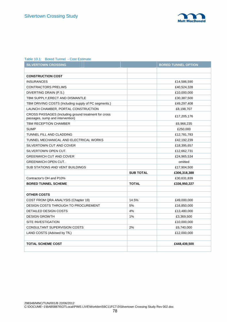
298348/MNC/TUN/001/B 22/06/2012 C:\DOCUME~1\BAB58876\OTLocal\PIMS LIVE\Workbin\59C11FC7.0\Silvertown Crossing Study Rev 002.doc
78
Silvertown Crossing Study
Table 10.1: Bored Tunnel - Cost Estimate
SILVERTOWN CROSSING BORED TUNNEL OPTION
CONSTRUCTION COST
INSURANCES £14,586,590
CONTRACTORS PRELIMS £40,524,328
DIVERTING DRAIN (P.S.) £10,000,000
TBM SUPPLY,ERECT AND DISMANTLE £30,387,500
TBM DRIVING COSTS (Including supply of PC segments.) £49,297,408
LAUNCH CHAMBER, PORTAL CONSTRUCTION £8,198,707
CROSS PASSAGES (Including ground treatment for cross passages, sump and intervention)
£17,205,176
TBM RECEPTION CHAMBER £6,966,235
SUMP £250,000
TUNNEL FILL AND CLADDING £12,781,783
TUNNEL MECHANICAL AND ELECTRICAL WORKS £42,192,239
SILVERTOWN CUT AND COVER £18,395,657
SILVERTOWN OPEN CUT. £12,662,731
GREENWICH CUT AND COVER £24,965,534
GREENWICH OPEN CUT. omitted
SUB STATIONS AND VENT BUILDINGS £17,904,500
SUB TOTAL £306,318,388
Contractor's OH and P10% £30,631,839
BORED TUNNEL SCHEME TOTAL £336,950,227
OTHER COSTS
COST FROM QRA ANALYSIS (Chapter 19) 14.5% £49,000,000
DESIGN COSTS THROUGH TO PROCUREMENT 5% £16,850,000
DETAILED DESIGN COSTS 4% £13,480,000
DESIGN GROWTH 1% £3,369,500
SITE INVESTIGATION £10,000,000
CONSULTANT SUPERVISION COSTS 2% £6,740,000
LAND COSTS (Advised by TfL) £12,000,000
TOTAL SCHEME COST £448,439,500
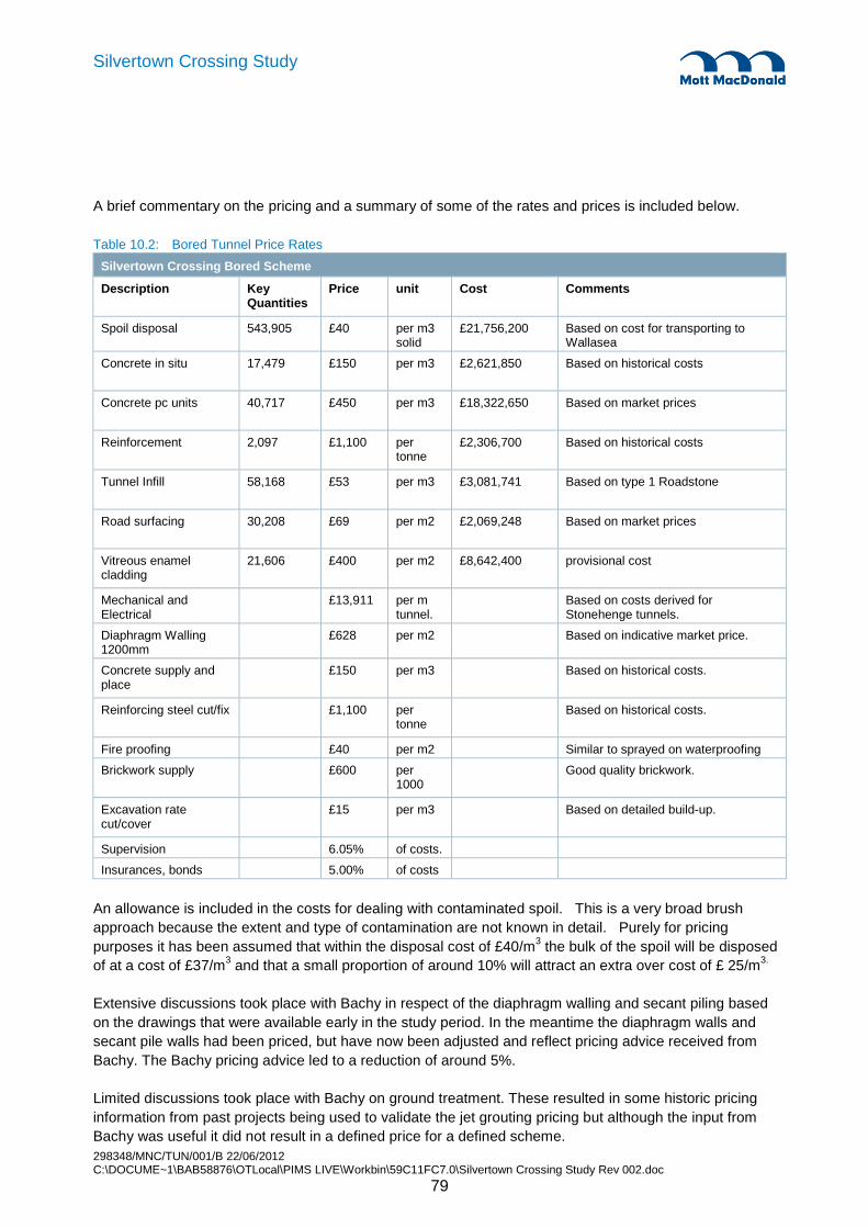
298348/MNC/TUN/001/B 22/06/2012 C:\DOCUME~1\BAB58876\OTLocal\PIMS LIVE\Workbin\59C11FC7.0\Silvertown Crossing Study Rev 002.doc
79
Silvertown Crossing Study
A brief commentary on the pricing and a summary of some of the rates and prices is included below.
Table 10.2: Bored Tunnel Price Rates
Silvertown Crossing Bored Scheme
Description Key Quantities
Price unit Cost Comments
Spoil disposal 543,905 £40 per m3 solid
£21,756,200 Based on cost for transporting to Wallasea
Concrete in situ 17,479 £150 per m3 £2,621,850 Based on historical costs
Concrete pc units 40,717 £450 per m3 £18,322,650 Based on market prices
Reinforcement 2,097 £1,100 per tonne
£2,306,700 Based on historical costs
Tunnel Infill 58,168 £53 per m3 £3,081,741 Based on type 1 Roadstone
Road surfacing 30,208 £69 per m2 £2,069,248 Based on market prices
Vitreous enamel cladding
21,606 £400 per m2 £8,642,400 provisional cost
Mechanical and Electrical
£13,911 per m tunnel.
Based on costs derived for Stonehenge tunnels.
Diaphragm Walling 1200mm
£628 per m2 Based on indicative market price.
Concrete supply and place
£150 per m3 Based on historical costs.
Reinforcing steel cut/fix £1,100 per tonne
Based on historical costs.
Fire proofing £40 per m2 Similar to sprayed on waterproofing
Brickwork supply £600 per 1000
Good quality brickwork.
Excavation rate cut/cover
£15 per m3 Based on detailed build-up.
Supervision 6.05% of costs.
Insurances, bonds 5.00% of costs
An allowance is included in the costs for dealing with contaminated spoil. This is a very broad brush approach because the extent and type of contamination are not known in detail. Purely for pricing purposes it has been assumed that within the disposal cost of £40/m3 the bulk of the spoil will be disposed of at a cost of £37/m3 and that a small proportion of around 10% will attract an extra over cost of £ 25/m3.
Extensive discussions took place with Bachy in respect of the diaphragm walling and secant piling based on the drawings that were available early in the study period. In the meantime the diaphragm walls and secant pile walls had been priced, but have now been adjusted and reflect pricing advice received from Bachy. The Bachy pricing advice led to a reduction of around 5%.
Limited discussions took place with Bachy on ground treatment. These resulted in some historic pricing information from past projects being used to validate the jet grouting pricing but although the input from Bachy was useful it did not result in a defined price for a defined scheme.

298348/MNC/TUN/001/B 22/06/2012 C:\DOCUME~1\BAB58876\OTLocal\PIMS LIVE\Workbin\59C11FC7.0\Silvertown Crossing Study Rev 002.doc
80
Silvertown Crossing Study
The Vitreous Enamel cladding is a cost that may be partly avoidable. If VE cladding is omitted there will be some form of alternative finish but there is scope for a net saving.
The price for substations and ventilation buildings is broad brush pricing. It does include for car parking and service road access to the buildings. It also allows for a modest architectural cladding to the exhaust stacks at each ventilation building.
The cost tabulated above does not include a fire suppression system. Pricing guidance from previous projects has been validated by an estimate for Silvertown from Aquasys and after adding on appropriate allowance for items excluded from the Aquasys estimate a sum of £4M would be an appropriate allowance for the addition of a fire suppression system. However, we believe that an early decision to include a fire suppression system as part of a fully engineered approach to fire safety would not lead to any overall increase in cost.

298348/MNC/TUN/001/B 22/06/2012 C:\DOCUME~1\BAB58876\OTLocal\PIMS LIVE\Workbin\59C11FC7.0\Silvertown Crossing Study Rev 002.doc
81
Silvertown Crossing Study
11.1 General
The immersed tunnel form of construction is less familiar to the majority of scheme promoters and the construction industry in general compared to a bored tunnel solution. Therefore a simple description of the principles behind the construction method is given in this section of the report, followed by a description of the outline design that has been developed.
The essential components of an immersed tunnel are:
• The immersed tunnel is built in the dry, usually in a purpose built casting basin, as a series of tunnel elements that are typically between 100m and 150m in length.
• The tunnel elements are cellular box structures through which the road or railway will pass. They are usually reinforced concrete structures, though historically some tunnels have been built in the US and Asia as steel structures.
• The tunnel elements are sealed at the ends with temporary bulkheads and this enables them to be floated.
• The elements are also fitted with temporary internal ballasting systems that control whether the tunnel floats or sinks.
• The casting basin will be below water level so that it can be flooded and the tunnel elements floated out of it.
• If the casting basin is not at the crossing site the tunnel elements are towed to the site using tugs.
• A trench is dredged in the bed of the waterway into which the tunnel elements can be sunk.
• One or both of the approach tunnels is constructed before the first immersed tunnel is placed.
• The first tunnel element is sunk into position either onto temporary supports or directly onto a gravel bed, up against the approach tunnel.
• The joint between the tunnel element and the approach tunnel is sealed using a heavy rubber “Gina” gasket that runs around the full perimeter of the element section.
• When the tunnel element is placed it traps water between the opposing bulkheads of the element and the approach tunnel, within the Gina gasket.
• When the water is pumped out the out of balance hydrostatic pressure acting on the element forces it to close up to the approach tunnel.
• The remaining tunnel element are immersed in sequence one against the next until the string of tunnel elements is complete.
11. Immersed Tube Tunnel – Design Solution

298348/MNC/TUN/001/B 22/06/2012 C:\DOCUME~1\BAB58876\OTLocal\PIMS LIVE\Workbin\59C11FC7.0\Silvertown Crossing Study Rev 002.doc
82
Silvertown Crossing Study
• Elements can be placed from both approaches towards the middle of the river. Leaving a small gap between the last two elements placed. This is filled with and insitu stitch called a closure joint.
• Alternatively tunnel elements can be placed from one side of the waterway to the other leaving the last tunnel element in a cofferdam in the river wall. The cut and cover tunnel is then completed afterwards.
• The tunnel elements are backfilled within the trench and a layer of rock protection is placed over the structure.
• The internal finishing works can then commence, placing permanent ballast, forming the road or railway and installing cladding and M&E systems.
The solution developed for the Silvertown Tunnel is based on this procedure with the first tunnel element placed against the Greenwich cut and cover tunnel and the last placed on the Silvertown approach in a cofferdam at the river wall.
11.2 Alignment Development
The horizontal alignment of the tunnel follows the alignment that has been safeguarded by TfL. The width of the immersed tunnel structure is less than the twin bored tunnel solution and this has enabled the alignment to be smoothed slightly as it passes beneath the cable car. The tie-in points are as per the bored tunnel in Silvertown and Greenwich.
The vertical alignment of the tunnel has been developed by setting the top of the tunnel roof as a depth of 1.5m below the river bed at the low point of the tunnel. The 1.5m clearance is provided as a minimum to enable a layer of rock protection to be placed over the tunnel to protect it from the impact of falling objects or sinking vessels. To either side of the low point a gradient of 4% is used to bring the tunnel to the surface behind the river walls. Due to constraints on each side of the river the tunnel portals can not be placed at the points to give the minimum crossing length. On the Greenwich approach the future residential developments identified in the Greenwich Masterplan make it undesirable to bring traffic to the surface with a ramp immediately behind the river wall. The tunnel has therefore been extended such that the portal is at the western end of the planned development, at the same position as the bored tunnel solution.
At Silvertown the road could reach ground level immediately beneath the cable car between the north main tower and north intermediate tower. This is seen as undesirable as the intention is to have the air cleaning facility along with ventilation tower at the portal. Immediately west of the cable car there is only a short distance to the DLR viaduct which again is not seen as a viable location to site the tunnel portal. The cut and cover tunnel has therefore been extended past the DLR viaduct to enable traffic to reach ground level to the west of DLR and the portal to be located where the air cleaning facility and associated tower can sensibly be sited.
These extensions of the cut and cover length mean the road does not come directly to the ground surface and hog curves are introduced into the vertical alignment so that the cut and cover tunnels can run just below the ground surface. These constraints have a big influence on the immersed tunnel scheme as an 865m tunnelled length becomes a 1380m tunnelled length, an increase of 60% over what would be the crossing length without the constraints.
The interface between the immersed tunnel and the cut and cover tunnel sections have been developed on the basis of minimising the temporary works extending into the river. The interface on the Greenwich side is

298348/MNC/TUN/001/B 22/06/2012 C:\DOCUME~1\BAB58876\OTLocal\PIMS LIVE\Workbin\59C11FC7.0\Silvertown Crossing Study Rev 002.doc
83
Silvertown Crossing Study
therefore 10m behind the river wall and the interface on the Silvertown side coincides with the line of the river wall.
11.3 Structural Form
11.3.1 Immersed Tube Tunnel
The immersed tunnel structure is a three cell reinforced concrete three cell box structure. The total immersed length between the approach cut and cover tunnels is 488m. This length is subdivided into four tunnel elements, each with an equal length of 122m.
There are two choices available as to the structure of the tunnel elements. They can either be constructed as continuous monolithic structures, or they can be subdivided into a series of match-cast segments. The latter form of structure has been selected as this has been seen to be slightly more cost effective within Europe for shallow river crossings.
The structure will be a watertight construction. To achieve this, the tunnel elements will be divided into five equal length segments with a length of 24m. This length allows cracking due to early thermal and shrinkage effects to be eliminated by the use of concrete cooling techniques during the curing period of the concrete. This is a conventional construction approach for this type of immersed tunnel that has been well demonstrated as effective within Europe. No external waterproofing membrane is required with this method of construction. The joints between each match cast segment will contain a cast-in grout-injectible waterbar combined with a second external waterstop to give double protection against leakage.
In order to float the tunnel element, transport and immerse it into the dredged trench the segments will be clamped together with temporary prestressing. This is within cast-in ducts in the base and roof slab of the tunnel elements. The prestress tendons are grouted as a permanent prestressing arrangement would be, but once the tunnel element is immersed the prestress will be cut in order to allow the tunnel segments to articulate.
Each tunnel element will be connected to the next with an immersion joint that features a double watertight gasket. The initial seal formed during the immersion process will be made with a Gina gasket and the second seal will be fixed following the immersion process and will be an omega gasket. Both seals are mounted on a steel end frame cast into the ends of the tunnel elements. This is a conventional arrangement for immersed tunnels and is a highly reliable system for providing watertightness. Corrosion protection of the steelwork is achieved by the application of a cathodic protection system.
Both the immersion joints and segment joints will allow opening and closing and rotation once the tunnel is constructed. The joints will contain shear keys within each wall and within the roof slab and base slab to ensure no relative movement can occur between adjacent segments or elements either in the vertical or horizontal direction.
The tunnel will have a thick layer of mass concrete placed in its base to serve as ballast and give the structure the necessary weight to achieve a factor of safety against uplift of approximately 1.1 in its completed condition. The ballast concrete will contain a drainage carrier pipe and gulleys to collect water from the road surface arising from washing, fire hydrants or spillages. Liquid will be transferred to the tunnel low point into a collection sump. The sump chamber is formed within the combined depth of the structural base slab and ballast concrete. The chamber will be formed by a series of connected cells to create sufficient storage capacity of approximately 50m3. Covers in the verges can be used to access the sump chamber for cleaning.

298348/MNC/TUN/001/B 22/06/2012 C:\DOCUME~1\BAB58876\OTLocal\PIMS LIVE\Workbin\59C11FC7.0\Silvertown Crossing Study Rev 002.doc
84
Silvertown Crossing Study
The immersed tunnel will be founded on a sand layer pumped beneath the tunnel after each element has been placed, by the sand flow method. No further foundation is anticipated as the quality of ground in the base of the dredged trench is believed to offer good support to the tunnel. Because the tunnel imparts a bearing load in the region of 25-30MPa global settlements will be small and the risk of differential settlement is low. As the tunnel is lighter than the weight of soil removed there could be a degree of heave experienced from the London Clay. This can be accounted for in the design of the structure and some allowance has been made in the internal clearance envelope to accommodate some small differential movements.
11.3.2 Cut and Cover Tunnels
The length of cut and cover construction is 552m on the Greenwich approach and 341m on the Silvertown approach. The approach tunnels will be formed using diaphragm walls as the main retaining wall element of the structure. This allows the footprint of the tunnel to be kept to a minimum which is a particular advantage through the Greenwich approach where adjacent developments are planned. It also enables a simple low cost watertight excavation to be formed as the diaphragm walls will pass down through the permeable surface strata and embed into the underlying impermeable strata. When the ground is excavated within the diaphragm walls the impermeable strata will provide a natural ground water cut-off layer and avoid the need for dewatering to draw down the ground water table and enable dry excavations to be formed. Thus any impact to adjacent properties, facilities or infrastructure is avoided.
After the diaphragm walls are installed the ground between them will excavated, using temporary propping as necessary to support the diaphragm walls. A reinforced concrete base slab and roof slab will be cast to form the tunnel structure. A waterproofing membrane will be laid in advance of casting the base slab and full structural connections will be made between slab and wall. This gives a good watertight connection. Diaphragm walls will feature a waterstop between the panels that gives a good level of watertightness. However as the watertightness of diaphragm wall panels is not as reliable as insitu concrete construction within formwork, an internal wall will be constructed on the inside of the diaphragm walls. This will allow drainage of any seepage though the diaphragm walls to be collected and channelled away, ensuring the internal finish remains dry at all times. In locations such as the crossing of the old Royal Victoria Dock entrance where obstructions are anticipated at depth then secant pile walls are likely to be used instead of diaphragm walls with the leakage controlled by the use of soft piles prior to construction of the main hard piles.
The length of cut and cover tunnel that will be constructed in the casting basin, once the tunnel elements have been removed, will be a conventional insitu RC box structure, very similar to the immersed tunnel section, except that it will not require internal ballast concrete, just a simple road construction on the base slab.
The cut and cover tunnels will be subject to a high water table throughout their length and must be designed to resist uplift due to floating behaviour. If the diaphragm walls or the weight of the structure and backfill do not offer sufficient resistance to this effect then additional tension piles can be installed. From the current study this is not thought to be necessary.
11.3.3 Ramps
The same construction methodology will be used for the open ramp structures that take the road alignment down to the tunnel portal. Diaphragm walls will be used to form the main retaining structure and a structural reinforced concrete slab will be cast between the walls just below the road level. As with the cut and cover

298348/MNC/TUN/001/B 22/06/2012 C:\DOCUME~1\BAB58876\OTLocal\PIMS LIVE\Workbin\59C11FC7.0\Silvertown Crossing Study Rev 002.doc
85
Silvertown Crossing Study
section the tensile resistance of the diaphragm walls will be used to resist uplift and an internal lining wall will be used for drainage and aesthetics.
11.4 Tunnel Finishes
Footways that are a minimum of 1.0m wide with 75mm kerbs will be formed on top of the ballast concrete and a wearing course built up in two layers will be placed directly onto the ballast concrete. The ballast concrete will be finished with a close tolerance screeding blade in order to facilitate this.
The inside faces of the external walls of the tunnel, and the tunnel roof slab will have a passive fire protection material applied. The protection layer will extend down a distance of 1.0m on the internal walls. The fire protection may be a board system or a spray applied system. Both have been used successfully in immersed tunnels around the world and offer a similar level of protection to the structure. A 35mm thickness allowance has been made which will accommodate any of the systems available on the market to provide a level of fire resistance to suit a fire with heat development in accordance with the RWS fire curve or HCM modified hydrocarbon curve.
Over the height of 4m above the back of verge level the tunnel walls will be clad for aesthetic and reflectance purposes. The cladding could be formed from a variety of systems, from a vitreous enamel cladding mounted on a support framework to a simple hard wearing coating that is integral with the fire protection material applied to the walls. Space provision is made for a framed solution.
11.5 Service Buildings
Service buildings are located at each tunnel portal. These are common to both the immersed tunnel solution and the bored tunnel solution and so are not described further here.
11.6 Design Options
11.6.1 Omission of Central Escape Gallery
For short immersed tunnels it is not uncommon to omit a central gallery. Examples are the Medway Tunnel, Bjørvika tunnel (in Oslo, opened 2010) and the Limerick Tunnel (opened 2011). There are operational benefits with the gallery but the lack on one does not make the tunnel intrinsically unsafe. Escape doors are still provided at 100m centres and operational procedures can be developed to manage the safe evacuation of car passengers from the tunnel in the event of a fire.
The option for a tunnel without the gallery clearly reduces cost as the dredging width and the structure width reduces by approximately 2m. All aspects of design and construction of the immersed tunnel are similar and the programme is little affected. The cross section for this solution is show on drawing number MMD-298348-TUN-305.
For the purposes of this study this option has not been carried through the scheme development and costings as it would be un-conservative assumption. However it could present an opportunity in the future, subject to the satisfactory development of the operational strategies.

298348/MNC/TUN/001/B 22/06/2012 C:\DOCUME~1\BAB58876\OTLocal\PIMS LIVE\Workbin\59C11FC7.0\Silvertown Crossing Study Rev 002.doc
86
Silvertown Crossing Study
12.1 General
The proposed tunnel provides a dual 2 lane all traffic connection between the A102 on Greenwich Peninsula and the Tidal basin roundabout on Silvertown Way.
Road Safety Regs 2007 regulations came into force on the 22nd June 2007. They apply in relation to a road tunnel in the UK that is:
a) Over 500m in length and that forms part of the Trans-European Road Network.
b) Whether it is in operation or at the construction stage or the design stage.
The above is based on the EU Directive 2004/54/EC (29th April 2004) on minimum safety standards for road tunnels on the Trans-European Road Network came into force. This Directive is intended to harmonise the technical requirements and organisation of safety across Europe.
The European Parliament has expressed its desire for comparable safety levels to be implemented in all road tunnels across the Europe. The Silvertown tunnels would not lie on the Trans-European Road Network (TERN). Therefore the directive would be applied only were it is reasonable and practical to do so.
The assumption would be to adhere to the principles of the HA standards, e.g. BD 78/77 – Design of Road Tunnels.
12.2 Alignment
The horizontal and vertical alignment of the bored tunnels has been reviewed to take account of the latest design of the London Cable Car. Clearances from the cable car south pier foundation are generally improved compared to the bored tunnel because of the narrower footprint of the structure.
The alignment developed is based upon standards published by the Highways Agency, principally:
• TD 27/05 – Cross-Sections and Headrooms
• BD 78/77 – Design of Road Tunnels
• TD 9/93 – Highway Link Design
The speed limit within the tunnel and on the approach roads is 30mph, giving a design speed according to BD78/99 Table 4.3 of 60km/h. At this speed the desirable stopping site distance (SSD) is 90m.
12. Immersed Tube Tunnel - Design Criteria
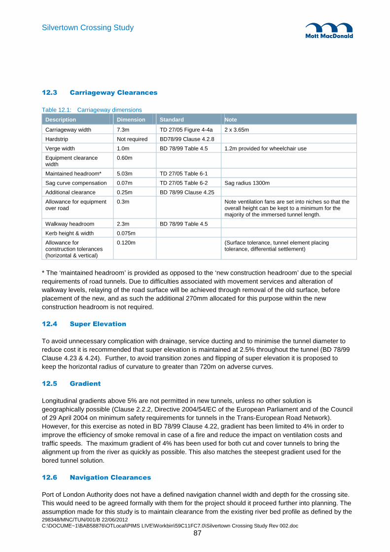
298348/MNC/TUN/001/B 22/06/2012 C:\DOCUME~1\BAB58876\OTLocal\PIMS LIVE\Workbin\59C11FC7.0\Silvertown Crossing Study Rev 002.doc
87
Silvertown Crossing Study
12.3 Carriageway Clearances
Table 12.1: Carriageway dimensions
Description Dimension Standard Note
Carriageway width 7.3m TD 27/05 Figure 4-4a 2 x 3.65m
Hardstrip Not required BD78/99 Clause 4.2.8
Verge width 1.0m BD 78/99 Table 4.5 1.2m provided for wheelchair use
Equipment clearance width
0.60m
Maintained headroom* 5.03m TD 27/05 Table 6-1
Sag curve compensation 0.07m TD 27/05 Table 6-2 Sag radius 1300m
Additional clearance 0.25m BD 78/99 Clause 4.25
Allowance for equipment over road
0.3m Note ventilation fans are set into niches so that the overall height can be kept to a minimum for the majority of the immersed tunnel length.
Walkway headroom 2.3m BD 78/99 Table 4.5
Kerb height & width 0.075m
Allowance for construction tolerances (horizontal & vertical)
0.120m (Surface tolerance, tunnel element placing tolerance, differential settlement)
* The ‘maintained headroom’ is provided as opposed to the ‘new construction headroom’ due to the special requirements of road tunnels. Due to difficulties associated with movement services and alteration of walkway levels, relaying of the road surface will be achieved through removal of the old surface, before placement of the new, and as such the additional 270mm allocated for this purpose within the new construction headroom is not required.
12.4 Super Elevation
To avoid unnecessary complication with drainage, service ducting and to minimise the tunnel diameter to reduce cost it is recommended that super elevation is maintained at 2.5% throughout the tunnel (BD 78/99 Clause 4.23 & 4.24). Further, to avoid transition zones and flipping of super elevation it is proposed to keep the horizontal radius of curvature to greater than 720m on adverse curves.
12.5 Gradient
Longitudinal gradients above 5% are not permitted in new tunnels, unless no other solution is geographically possible (Clause 2.2.2, Directive 2004/54/EC of the European Parliament and of the Council of 29 April 2004 on minimum safety requirements for tunnels in the Trans-European Road Network). However, for this exercise as noted in BD 78/99 Clause 4.22, gradient has been limited to 4% in order to improve the efficiency of smoke removal in case of a fire and reduce the impact on ventilation costs and traffic speeds. The maximum gradient of 4% has been used for both cut and cover tunnels to bring the alignment up from the river as quickly as possible. This also matches the steepest gradient used for the bored tunnel solution.
12.6 Navigation Clearances
Port of London Authority does not have a defined navigation channel width and depth for the crossing site. This would need to be agreed formally with them for the project should it proceed further into planning. The assumption made for this study is to maintain clearance from the existing river bed profile as defined by the

298348/MNC/TUN/001/B 22/06/2012 C:\DOCUME~1\BAB58876\OTLocal\PIMS LIVE\Workbin\59C11FC7.0\Silvertown Crossing Study Rev 002.doc
88
Silvertown Crossing Study
latest bathymetric survey. This offers a water depth of 7m over a width of approximately 200m, and a deeper 10m channel to the Silvertown side of approximately 100m.
The Greenwich side of the river shallows beyond the North Greenwich Pier and the main channel then becomes narrower around the tip of the Greenwich Peninsula. The larger vessels using this stretch of the river therefore cross the tunnel site on the Silvertown side of the channel. The Greenwich side of the channel has mobile shoals that migrate along the river frontage and result in a depth of water that may vary by 1-2m over a short period of time.
The Port of London Authority noted that an additional clearance may be required to enable the river bed mobility to continue unimpeded. This has not been allowed for at the present time as it would be subject to further discussion with the PLA and EA to define the criteria.
12.7 Vertical Stability and Buoyancy
Immersed tunnel
Minimum freeboard when floating 0.3m
Factor safety against uplift in temporary conditions 1.025
Min factor of safety in permanent condition 1 1.06
Min factor of safety in permanent condition incl. rock cover 2 1.1
Cut and cover tunnels
Load factors applied in determining resistance against uplift:
Hydrostatic uplift pressures 1.1
Self weight of structure and fill 0.9
In addition a factor of safety of 2.5 is assumed when taking account of tension pile contribution to resistance to uplift.
12.8 Hydrographic Parameters
The following hydographic parameters have been used.
Tide data:
• MHWS +3.76m
• MHW +3.17m
• MHWN +2.59m
• MW 0 000 (OD)
298348/MNC/TUN/001/B 22/06/2012 C:\DOCUME~1\BAB58876\OTLocal\PIMS LIVE\Workbin\59C11FC7.0\Silvertown Crossing Study Rev 002.doc
89
Silvertown Crossing Study
• MLWN -1.95m
• MLWS -2.90m
• LAT (chart datum) -3.35m
Current Data:
• Maximum current speed is taken as 4 knots.
12.9 Watertightness
Immersed tunnels are designed to be watertight structures. As such no leakage is permitted and any leakage of the initial construction would need to be rectified to preserve the durability of the structure for its intended design life. The form of structure chosen has been constructed as a watertight structure in many locations around Europe.
The cut and cover tunnels, where formed by insitu construction techniques in the area of the casting basin should fulfil the same performance criteria as the immersed tunnel. Where constructed using diaphragm walls and insitu slabs, the diaphragm walls may be permitted a degree of seepage due to the nature of their construction. This would typically be 0.12 litres/day. Diaphragm walls will be lined with a drainage gap between the lining and the diaphragm walls.
12.10 Flood Protection
The existing river walls have a flood protection level of +5.23m AOD. This level will be maintained for the temporary works cofferdams when river walls are removed, and for the reinstated river walls.
12.11 Accidental Loads
The tunnel will need to be designed to withstand the following accidental loads, which is conventional design approach for immersed tunnels:
• Sinking ship (size to be determined according to shipping)
• Falling anchor (size to be determined according to shipping)
• Explosion (100kN/m2 internal overpressure)
• Fire (RWS curve)
• Loss of support (over one segment length)
• Flooding (partial or full flooding of tunnel)
The preliminary tunnel sizing takes these into account and final design for these loads will be possible.

298348/MNC/TUN/001/B 22/06/2012 C:\DOCUME~1\BAB58876\OTLocal\PIMS LIVE\Workbin\59C11FC7.0\Silvertown Crossing Study Rev 002.doc
90
Silvertown Crossing Study
12.12 Structural Design
At this stage of scheme development preliminary sizing of the structure is undertaken only. For immersed tunnels the sizing is based largely on the buoyancy characteristics rather than structural adequacy, but checked using a simple span/depth ratio approach. Ultimately the structure would be designed to Eurocodes and the preliminary sizing presented on the drawings is capable of being developed into a final scheme using those standards.
There are some specific aspects of designing an immersed tunnel structure that will need to be taken into account, but they will not fundamentally change the scheme from the solution presented.
12.13 Tunnel Ventilation
The tunnel will be ventilated longitudinally in the direction of traffic flow (to ensure ventilation in normal operation and provide smoke control in the event of an emergency) using jet fans located in the tunnel roof within niches above the traffic envelope. Fans would be spaced through the cut and cover tunnels and the immersed tunnel but would be kept clear of the main navigation channel to avoid the need for and increased height structure in this zone, and hence any increased depth of dredging.
Exhaust chimneys will be located adjacent to the cut and cover portal on the outbound tunnels to conduct vitiated air vertically clear of adjacent buildings, with fans located in a double stacked configuration. The solution adopted is common with the bored tunnel and the chimneys have been assumed to be 45m high and would be constructed from concrete with an appropriate architectural finish to be sympathetic with the surrounding development.
Jet fans at the tunnel portals will be reversible so that they may be used in the event of an in-tunnel fire incident to increase the relative pressure in the non-incident tunnel and thereby prevent passage of smoke from incident to the non-incident bore.
12.14 Consultations with the PLA
A consultation meeting was held with the Port of London Planning Authority (PLA) on 23 January 2012. Minutes from the meeting and a follow-up letter from the PLA identifying their areas of concern are contained in Appendix F . The main points arising are summarised as:
• River closures though undesirable may be possible to organise over weekends during the winter season.
• Numerical modelling of the river dynamics will be required
• Loss of foreshore habitat and compensation habitat creation will nee to be agreed with the EA
• Towing of tunnel elements by tug along Thames from the mouth of the estuary to the tunnel crossing site would need to be carried out in stages and require significant logistical planning including the identifying/creating of temporary berths along the tow route.
• No significant difficulties were identified associated with towing through the Thames barrier
• River closures might lead to compensation claims from businesses using the river

298348/MNC/TUN/001/B 22/06/2012 C:\DOCUME~1\BAB58876\OTLocal\PIMS LIVE\Workbin\59C11FC7.0\Silvertown Crossing Study Rev 002.doc
91
Silvertown Crossing Study
• Notice of closures would be required 4-6 months in advance.
• Thorough assessment, restrictions and monitoring will be placed in particular relation to oxygen levels and suspended solids in the water column.
• Passage of large ships would be prioritised.

298348/MNC/TUN/001/B 22/06/2012 C:\DOCUME~1\BAB58876\OTLocal\PIMS LIVE\Workbin\59C11FC7.0\Silvertown Crossing Study Rev 002.doc
92
Silvertown Crossing Study
A summary of the key environmental issues for the scheme alignment are highlighted in Section 5 of this report. The following section identifies environmental issues and concerns specifically relating to the immersed tunnel option.
13.1 Air Quality
There are not anticipated to be any additional impacts from the immersed tunnel option other than those identified in Section 5 .
13.2 Archaeology
The baseline archaeological conditions are provided in Section 5 of this report.
Given that the immersed tunnel option, when compared with the bored tunnel, requires a greater area of land to be constructed using either open cut or cut and cover construction methods there is greater potential to disturb archaeological remains within the areas of archaeological potential as designated by the London Boroughs of Greenwich and Newham.
The immersed tunnel will also require a channel to be dredged in the River Thames. This is likely to remove any archaeological resources located within the Archaeological Priority Area designated by the London Borough of Newham which extends to the centre of the River Thames.
It is anticipated that further archaeological work will be required to assess the potential impact the scheme will have on archaeological resources and required mitigation measures such as archaeological watching briefs to be undertaken during the construction of the scheme.
13.3 Biodiversity
The baseline biodiversity conditions are provided in Section 5 of this report.
The need to undertake construction works and dredging within the river to construct an immersed tunnel could result in the deterioration of water quality, elevated suspended sediments in the river and the loss of intertidal mudflats during construction and during operation if permanent structures are needed in the river.
Aquatic species - Studies undertaken as part of London Cable Car show the River Thames and some of its tributaries are well established as providing an important nursery area for many juvenile fish. Fish surveys undertaken by the Environment Agency at Greenwich and Greenwich - Teddington recorded 19 species and 26 species, respectively from 2000 to 2010. These include the river lamprey Lampetra fluviatilis and sea lamprey Petromyzon marinus, European smelt Osmerus eperlanus, atlantic salmon Salmo salar, sea/brown trout Salmo trutta, European eel Anguilla anguilla and Twaite shad Alosa fallax. The construction of an immersed tunnel has the potential to prevent adult fish from migrating upstream to possible spawning grounds and result in mortality in younger fish. In addition, mobilisation of contaminated sediments has the potential to cause some direct toxicological effects leading to impairment of physiological functions in fish.
The PLA and the Environment Agency are particularly sensitive to the combined effects of dredging, outfalls and development during the summer months of June to August when dissolved oxygen levels are
13. Immersed Tube Tunnel – Environmental Issues

298348/MNC/TUN/001/B 22/06/2012 C:\DOCUME~1\BAB58876\OTLocal\PIMS LIVE\Workbin\59C11FC7.0\Silvertown Crossing Study Rev 002.doc
93
Silvertown Crossing Study
at their lowest. In addition the PLA are sensitive to dredging operations fish spawning period of March to May and nursery period of July to September/October. As such the PLA advise that where possible and economically viable, dredging operations should be planned to avoid this period. In the absence of scientific evidence to demonstrate that dredging will not affect juvenile/spawning fish the PLA is taking a precautionary approach in recognising the increased sensitivity during nursery and spawning periods.
Intertidal Habitats - The River Thames is a site of Site of Importance for Nature Conservation. The environmental impact of the proposals needs to be fully considered with the aim of having a positive effect on biodiversity. Any loss of intertidal habitat should be mitigated for like-for-like, in close proximity to the loss.
The option for an immersed tunnel will impact on the River Thames and Tidal Tributaries SINC which supports some habitats of conservation importance (e.g. intertidal mudflats) and ecological important biota (e.g. birds and fish). The potential impacts of this will include:
• the temporary loss of intertidal mudflat habitat and associated benthos from the construction of the immersed tunnel;
• temporary disturbance to intertidal mudflat and associated benthos resulting in temporary disturbance to bird communities caused through installation of the cofferdams;
• a temporary reduction in water quality as a result of an increase in suspended solids and release of contaminant bound sediments causing temporary effects in fish and other biota during the dredging and construction phase of the works; and
• a temporary increase in aquatic noise levels during the installation of the immersed tunnel which could have adverse effects on marine mammals and fish.
Given the objections raised by the environment agency regarding the small loss of intertidal mudflats as a result of the London Cable Car project the use of an immersed tunnel option in likely to result in objections from the Environment Agency and the requirement for substantial mitigation measures such as the provision of like for like compensatory or like for like habitat creation to reduce the effect of the scheme. Obtaining approval to undertake the works and potential costs of such mitigation represent a significant risk to the use of an immersed tunnel.
13.4 Ground Contamination
Ground contamination issues are discussed in Section 5. There is a greater amount of excavation required for the casting basin for the immersed tube option at the Silvertown end.
13.5 Heritage
The baseline heritage conditions and potential impacts are provided in Section 5 of this report.
There are not anticipated to be any significant additional impacts from the immersed tunnel option other than those identified in Section 5 .
298348/MNC/TUN/001/B 22/06/2012 C:\DOCUME~1\BAB58876\OTLocal\PIMS LIVE\Workbin\59C11FC7.0\Silvertown Crossing Study Rev 002.doc
94
Silvertown Crossing Study
13.6 Landscape & Townscape
The baseline landscape and townscape conditions and potential impacts are provided in Section 5 of this report.
There are not anticipated to be any significant additional impacts from the immersed tunnel option other than those identified in Section 5.
13.7 Noise & Vibration
The baseline noise and vibration conditions and potential impacts are provided in Section 5 of this report.
There are not anticipated to be any significant additional impacts from the immersed tunnel option other than those identified in Section 5 .
13.8 Waste Management
The immersed tunnel will result in waste material from both the excavation of the open cut and cut and cover passages at the entrance and exits from the tunnel and from the dredged channel in which the immersed tunnel will be constructed within the River Thames.
The immersed tunnel option will require the construction of a dredged channel. Government policy encourages the beneficial use of dredged material rather than its disposal. In the Thames Estuary, the great majority of dredged material is either retained within the sedimentary system using water injection dredging, or taken to a beneficial use site at either Rainham (Essex) or Cliffe (Kent) which are managed by the RSPB for nature conservation. When applying for an application for a dredging licence contractors are required to consider the eventual location of dredged waste.
13.9 Water Resources and Flood Protection
13.9.1 Dredging
Dredging in the Thames Estuary is regulated by the Port of London Authority (PLA) by means of an application under Section 73 of the Port of London Act 1968. When considering a dredging licence application, the PLA is required by Section 48a of the Harbours Act 1964 to ‘have regard to:
• the conservation of the natural beauty of the countryside and of flora, fauna and geological or physiographical features of interest;
• the desirability of preserving for the public any freedom of access to places of natural beauty; and
• the desirability of maintaining the availability to the public of any facility for visiting or inspecting any building, site or object of archaeological, architectural or historic interest.’
13.9.2 Surface Water
Given the need for dredging and the construction of the immersed tunnel within the River Thames it is anticipated that the Environment Agency will have significant concerns regarding the impact of the scheme on changes to water level, flow paths and dynamics and the movement of sediment within the River. In light
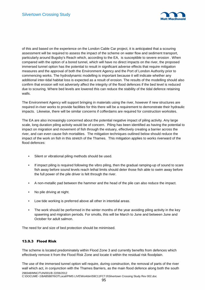
298348/MNC/TUN/001/B 22/06/2012 C:\DOCUME~1\BAB58876\OTLocal\PIMS LIVE\Workbin\59C11FC7.0\Silvertown Crossing Study Rev 002.doc
95
Silvertown Crossing Study
of this and based on the experience on the London Cable Car project, it is anticipated that a scouring assessment will be required to assess the impact of the scheme on water flow and sediment transport, particularly around Bugsby’s Reach which, according to the EA, is susceptible to severe erosion . When compared with the option of a bored tunnel, which will have no direct impacts on the river, the proposed immersed tunnel option has the potential to result in significant adverse effects that require mitigation measures and the approval of both the Environment Agency and the Port of London Authority prior to commencing works. The hydrodynamic modelling is important because it will indicate whether any additional inter-tidal habitat loss is expected as a result of erosion. The results of the modelling should also confirm that erosion will not adversely affect the integrity of the flood defences if the bed level is reduced due to scouring. Where bed levels are lowered this can reduce the stability of the tidal defence retaining walls.
The Environment Agency will support bringing in materials using the river, however if new structures are required in-river works to provide facilities for this there will be a requirement to demonstrate their hydraulic impacts. Likewise, there will be similar concerns if cofferdams are required for construction worksites.
The EA are also increasingly concerned about the potential negative impact of piling activity. Any large scale, long duration piling activity would be of concern. Piling has been identified as having the potential to impact on migration and movement of fish through the estuary, effectively creating a barrier across the river, and can even cause fish mortalities. The mitigation techniques outlined below should reduce the impact of the work on fish in this stretch of the Thames. This mitigation applies to works riverward of the flood defences:
• Silent or vibrational piling methods should be used.
• If impact piling is required following the vibro piling, then the gradual ramping-up of sound to scare fish away before sound levels reach lethal limits should deter those fish able to swim away before the full power of the pile driver is felt through the river.
• A non-metallic pad between the hammer and the head of the pile can also reduce the impact.
• No pile driving at night.
• Low tide working is preferred above all other in intertidal areas.
• The work should be performed in the winter months of the year avoiding piling activity in the key spawning and migration periods. For smolts, this will be March to June and between June and October for adult salmon.
The need for and size of bed protection should be minimised.
13.9.3 Flood Risk
The scheme is located predominately within Flood Zone 3 and currently benefits from defences which effectively remove it from the Flood Risk Zone and locate it within the residual risk floodplain.
The use of the immersed tunnel option will require, during construction, the removal of parts of the river wall which act, in conjunction with the Thames Barriers, as the main flood defence along both the south

298348/MNC/TUN/001/B 22/06/2012 C:\DOCUME~1\BAB58876\OTLocal\PIMS LIVE\Workbin\59C11FC7.0\Silvertown Crossing Study Rev 002.doc
96
Silvertown Crossing Study
and north banks of the river. During this process there will be a requirement to ensure that flood defence provisions are not compromised and approval/consent from the Environment Agency for works affecting watercourses and/or flood defences will be required prior to commencing works.
During the operation of the scheme it is proposed that reliance is placed on the flood protection works and no specific protection works at the tunnel entrances are required or will be provided.
Given the nature of the work and the size of the site it is anticipated that a formal flood risk assessment will be required to be undertaken and approved by the Environment Agency.
In addition, the following points would need to be avoided to prevent increased in relation to flood risk.
• Possible adverse loading and damage to the river walls / flood defences from the proposed structures.
• Loss of operational access to the tidal flood defences for their future raising and renewal. As well as the potential for impacts on the existing river wall structures, the loss of space could restrict options for any replacement river walls in the future.
13.9.4 Groundwater
The baseline groundwater conditions and potential impacts are provided in Section 5 of this report.
There are not anticipated to be any significant additional impacts from the immersed tunnel option other than those identified in Section 5.
13.10 River Dynamics
The two significant construction operations that will have an affect on the river dynamics will be the installation of cofferdams in the foreshore areas and the dredging works. Based out the knowledge of modelling the river for the cable car project the following impacts on the river dynamics can be anticipated.
13.10.1 Temporary Cofferdams
The temporary cofferdams will be required for a period in excess of 2 years. The installation plant will be floating craft and jack up platforms and will not have any significant adverse affect on the river flow regime. However once the cofferdams are installed they will block the river flow over the width of the foreshores.
The extent of the cofferdams has been limited to the edge of the tidal mudflats in order to avoid dredging of the environmentally sensitive mudflat areas. However they have not been extended beyond the low water line as that might cause a significant increase to the blockage of the river flow. In terms of volume the percentage reduction in the channel area is:
• Low water 0%
• High water between 1-1.5%

298348/MNC/TUN/001/B 22/06/2012 C:\DOCUME~1\BAB58876\OTLocal\PIMS LIVE\Workbin\59C11FC7.0\Silvertown Crossing Study Rev 002.doc
97
Silvertown Crossing Study
It is therefore not expected that this change to the channel will affect the flooding behaviour of the river. However detailed modelling will need to be undertaken to evaluate this and confirm the precise impacts and enable discussions to take place with the EA.
Flow speeds will be affected globally to the river flowing through the work sites and locally to the cofferdams where turbulence may be expected. This will be most severe when the cofferdams are first installed and before any dredging work has been carried out. A global increase is expected and there will be some increase in the volume of bed material that is taken into suspension, which would then naturally be deposited when the flow returns to its normal speed. As this additional pick up of material is over a very short distance it will not generate large volumes of deposition. It is anticipated that this can be managed through simple monitoring and survey of the bed behaviour and if necessary by a small amount of maintenance dredging work. Detailed modelling will be necessary, however, to quantify the extent of this behaviour and the magnitude of the materials involved.
Turbulence around the edge of the cofferdam may cause local scour at the channel side of the cofferdam where the wing walls return along the low water line. Again volumes of material picked up and deposited downstream of the cofferdam are expected to be small and can be managed with survey and maintenance dredging. In the sheltered water behind the cofferdam wing walls there is likely to be a degree of sediment deposition. Agreement will be necessary with the EA as to how this is managed. It may be acceptable to allow this to occur provided the rate of deposition is slow and to remove the excess material once the cofferdams are removed and the bed is returned to its previous condition. If the rate of deposition is fast there may need to be some maintenance dredging but any works will need to be carefully considered to ensure the mudflat is not unduly disturbed.
13.10.2 Dredging
The dredged trench will affect the flow regime of the river in that is represents a relatively sudden increase in water depth. This will cause current speeds to reduce and then increase back to their normal levels over the width of the trench, which is a distance of 65-70m. The affect of the cofferdam blockage at the foreshores will be to modify this slightly but the change to the flow area of the channel is heavily dominated by the increased depth due to dredging and so the overall behaviour will be a slowing of the flow through the site.
The phenomenon of trench migration is something that must be considered. This typically occurs where a steady flow in one direction is present, for example in canals and non-tidal waterways. As water passes over the trench the current speed drops and material in suspension is deposited on the downward slope of the trench. As current speed increases again as the trench begins to shallow erosion may occur and material may be picked up into suspension. This material is often deposited a short distance downstream as the watercourse returns to its normal regime. In a tidal waterway this behaviour reverses with each tide and is therefore largely self cancelling. However there could be a degree of deposition outside of the footprint of the dredged trench. As the majority of the dredging will cut through cohesive material the quantities of such material are expected to be negligible and this phenomenon is not expected to cause any issues environmentally.
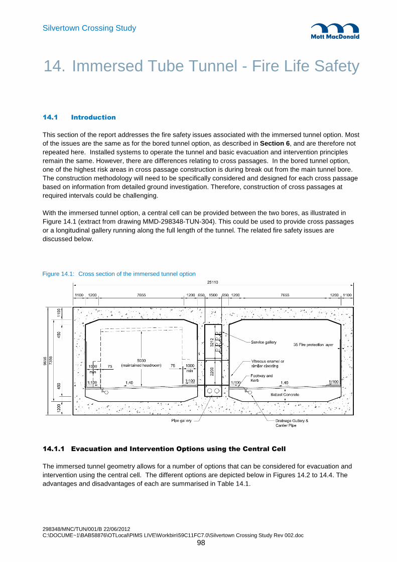
298348/MNC/TUN/001/B 22/06/2012 C:\DOCUME~1\BAB58876\OTLocal\PIMS LIVE\Workbin\59C11FC7.0\Silvertown Crossing Study Rev 002.doc
98
Silvertown Crossing Study
14.1 Introduction
This section of the report addresses the fire safety issues associated with the immersed tunnel option. Most of the issues are the same as for the bored tunnel option, as described in Section 6 , and are therefore not repeated here. Installed systems to operate the tunnel and basic evacuation and intervention principles remain the same. However, there are differences relating to cross passages. In the bored tunnel option, one of the highest risk areas in cross passage construction is during break out from the main tunnel bore. The construction methodology will need to be specifically considered and designed for each cross passage based on information from detailed ground investigation. Therefore, construction of cross passages at required intervals could be challenging.
With the immersed tunnel option, a central cell can be provided between the two bores, as illustrated in Figure 14.1 (extract from drawing MMD-298348-TUN-304). This could be used to provide cross passages or a longitudinal gallery running along the full length of the tunnel. The related fire safety issues are discussed below.
Figure 14.1: Cross section of the immersed tunnel option
14.1.1 Evacuation and Intervention Options using the Central Cell
The immersed tunnel geometry allows for a number of options that can be considered for evacuation and intervention using the central cell. The different options are depicted below in Figures 14.2 to 14.4. The advantages and disadvantages of each are summarised in Table 14.1.
14. Immersed Tube Tunnel - Fire Life Safety
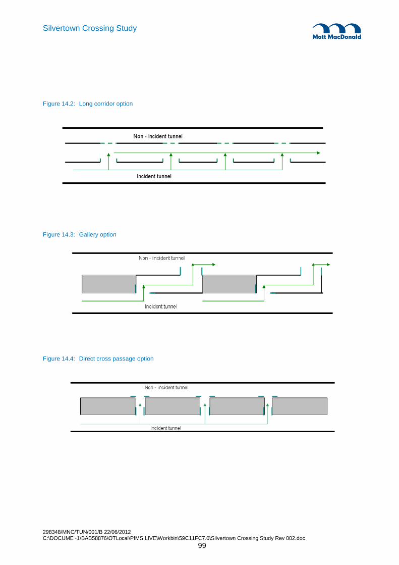
298348/MNC/TUN/001/B 22/06/2012 C:\DOCUME~1\BAB58876\OTLocal\PIMS LIVE\Workbin\59C11FC7.0\Silvertown Crossing Study Rev 002.doc
99
Silvertown Crossing Study
Figure 14.2: Long corridor option
Figure 14.3: Gallery option
Figure 14.4: Direct cross passage option
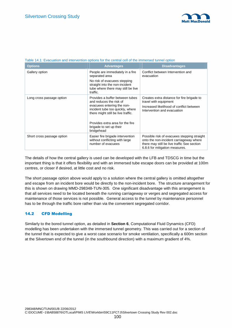
298348/MNC/TUN/001/B 22/06/2012 C:\DOCUME~1\BAB58876\OTLocal\PIMS LIVE\Workbin\59C11FC7.0\Silvertown Crossing Study Rev 002.doc
100
Silvertown Crossing Study
Table 14.1: Evacuation and intervention options for the central cell of the immersed tunnel option
Options Advantages Disadvantages
Gallery option People are immediately in a fire separated area
No risk of evacuees stepping straight into the non-incident tube where there may still be live traffic.
Conflict between Intervention and evacuation
Long cross passage option Provides a buffer between tubes and reduces the risk of evacuees entering the non-incident tube too quickly, where there might still be live traffic.
Provides extra area for the fire brigade to set up their bridgehead
Creates extra distance for fire brigade to travel with equipment
Increased likelihood of conflict between Intervention and evacuation
Short cross passage option Easier fire brigade intervention without conflicting with large number of evacuees
Possible risk of evacuees stepping straight onto the non-incident carriageway where there may still be live traffic See section 6.8.6 for mitigation measures.
The details of how the central gallery is used can be developed with the LFB and TDSCG in time but the important thing is that it offers flexibility and with an immersed tube escape doors can be provided at 100m centres, or closer if desired, at little cost and no risk.
The short passage option above would apply to a solution where the central gallery is omitted altogether and escape from an incident bore would be directly to the non-incident bore. The structure arrangement for this is shown on drawing MMD-298348-TUN-305. One significant disadvantage with this arrangement is that all services need to be located beneath the running carriageway or verges and segregated access for maintenance of those services is not possible. General access to the tunnel by maintenance personnel has to be through the traffic bore rather than via the convenient segregated corridor.
14.2 CFD Modelling
Similarly to the bored tunnel option, as detailed in Section 6 , Computational Fluid Dynamics (CFD) modelling has been undertaken with the immersed tunnel geometry. This was carried out for a section of the tunnel that is expected to give a worst case scenario for smoke ventilation, specifically a 600m section at the Silvertown end of the tunnel (in the southbound direction) with a maximum gradient of 4%.

298348/MNC/TUN/001/B 22/06/2012 C:\DOCUME~1\BAB58876\OTLocal\PIMS LIVE\Workbin\59C11FC7.0\Silvertown Crossing Study Rev 002.doc
101
Silvertown Crossing Study
Figure 14.5: Long section of the immersed tube tunnel
14.2.1 CFD results
Figures 14.6 to 14.9 present the results for temperatures, visibility and carbon monoxide respectively for the immersed tube tunnel. The figures focus on a 235m long extent of the tunnel. The normal traffic direction is from left to right. Vehicles are shown stopped behind the fire.
Visibility is generally the first indicator of loss of tenability. As illustrated in Figure 14.8: � At 2 minutes, approximately 50m of the tunnel behind the fire presents untenable conditions (i.e.
visibility falls below the 10m limit) due to smoke backlayering. � The smoke that has spread behind the fire starts to be pushed back after 4 minutes. � By 6 minutes, the area immediately behind the fire becomes smoke free.

298348/MNC/TUN/001/B 22/06/2012 C:\DOCUME~1\BAB58876\OTLocal\PIMS LIVE\Workbin\59C11FC7.0\Silvertown Crossing Study Rev 002.doc
102
Silvertown Crossing Study
Figure 14.6: Immersed tunnel – Temperature in vertical section through centre of fire
1 minute
2 minutes
3 minutes
4 minutes
5 minutes
6 minutes
15 minutes
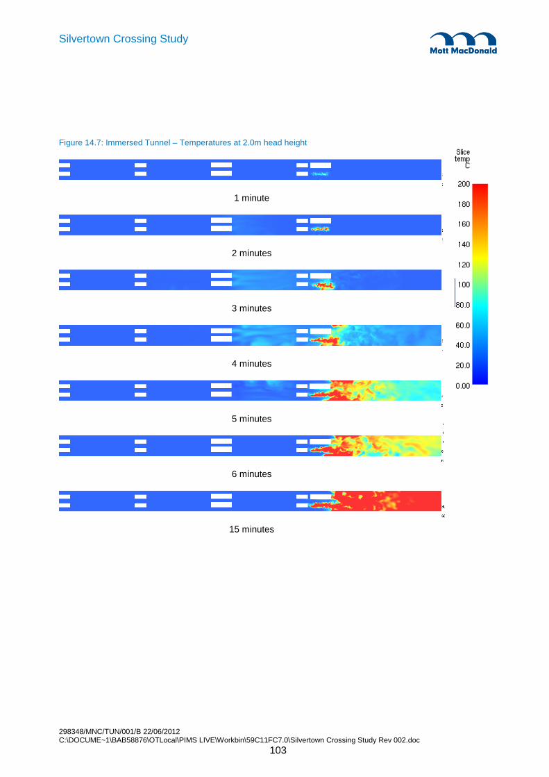
298348/MNC/TUN/001/B 22/06/2012 C:\DOCUME~1\BAB58876\OTLocal\PIMS LIVE\Workbin\59C11FC7.0\Silvertown Crossing Study Rev 002.doc
103
Silvertown Crossing Study
Figure 14.7: Immersed Tunnel – Temperatures at 2.0m head height
1 minute
2 minutes
3 minutes
4 minutes
5 minutes
6 minutes
15 minutes

298348/MNC/TUN/001/B 22/06/2012 C:\DOCUME~1\BAB58876\OTLocal\PIMS LIVE\Workbin\59C11FC7.0\Silvertown Crossing Study Rev 002.doc
104
Silvertown Crossing Study
Figure 14.8: Immersed Tunnel – Visibility at 2.0m head height
1 minute
2 minutes
3 minutes
4 minutes
5 minutes
6 minutes
15 minutes
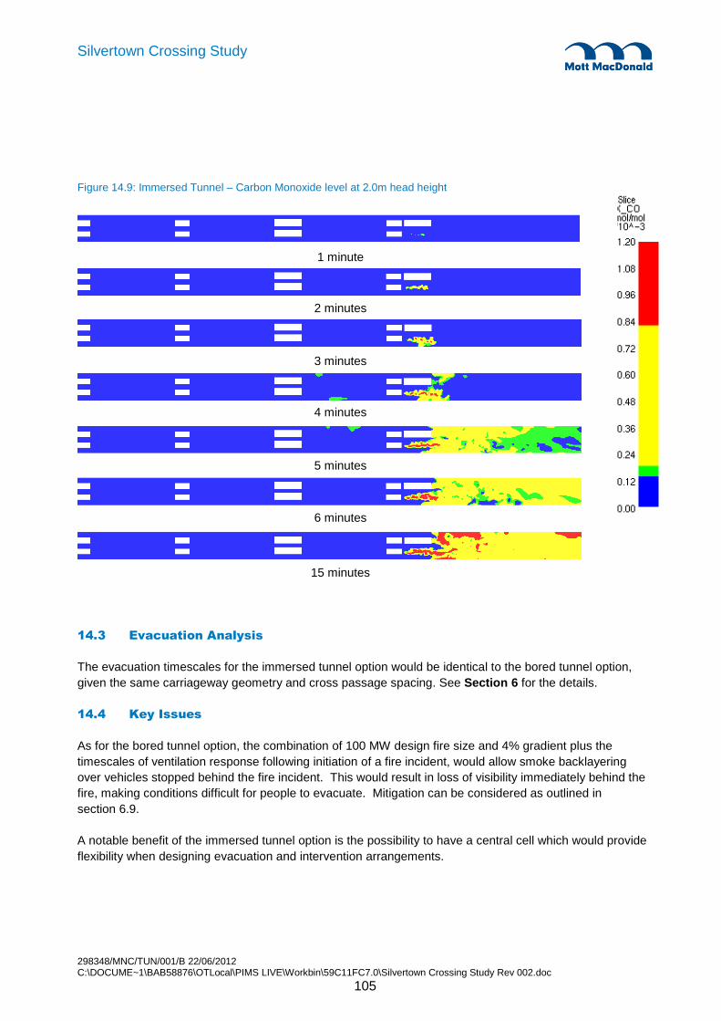
298348/MNC/TUN/001/B 22/06/2012 C:\DOCUME~1\BAB58876\OTLocal\PIMS LIVE\Workbin\59C11FC7.0\Silvertown Crossing Study Rev 002.doc
105
Silvertown Crossing Study
Figure 14.9: Immersed Tunnel – Carbon Monoxide level at 2.0m head height
1 minute
2 minutes
3 minutes
4 minutes
5 minutes
6 minutes
15 minutes
14.3 Evacuation Analysis
The evacuation timescales for the immersed tunnel option would be identical to the bored tunnel option, given the same carriageway geometry and cross passage spacing. See Section 6 for the details.
14.4 Key Issues
As for the bored tunnel option, the combination of 100 MW design fire size and 4% gradient plus the timescales of ventilation response following initiation of a fire incident, would allow smoke backlayering over vehicles stopped behind the fire incident. This would result in loss of visibility immediately behind the fire, making conditions difficult for people to evacuate. Mitigation can be considered as outlined in section 6.9.
A notable benefit of the immersed tunnel option is the possibility to have a central cell which would provide flexibility when designing evacuation and intervention arrangements.

298348/MNC/TUN/001/B 22/06/2012 C:\DOCUME~1\BAB58876\OTLocal\PIMS LIVE\Workbin\59C11FC7.0\Silvertown Crossing Study Rev 002.doc
106
Silvertown Crossing Study
15.1 Overview
The immersed tunnel elements will be constructed in a casting basin on the Silvertown approach. The Greenwich approach tunnel will be constructed in parallel to the construction of the tunnel elements. When the cut and cover tunnel next to the river wall is complete a temporary cofferdam will be constructed around it and the existing river wall will be removed to expose the end of the cut and cover tunnel to the river. Dredging will be carried out in parallel to the tunnel element construction such that when the elements have been completed the temporary cofferdam that serves as an entrance to the casting basin can be removed. The tunnel elements can then be removed from the basin one at a time and immersed progressively from Greenwich to Silvertown.
The last element will be placed such that it sits within the gate of the casting basin on a sill beam. The sill beam is then made continuous with a watertight collar installed around the tunnel which will enable the casting basin to be dewatered again. Once the basin has been dewatered the construction of the cut and cover tunnel will commence through the casting basin. When complete the casting basin will be infilled and the river wall will be reinstated.
A simplified sequence of construction is shown in the high level programme below. The full version of the programme is contained in Appendix C.
15.2 Selection of Tunnel Element Construction Site
One of the key decisions to be made for any immersed tunnel project is the site where the tunnel elements are to be constructed. Often the final choice for this is left to contractors in the design and construct contract, as they can determine the best value solution to this question at the time. However, for the purposes of early planning and preparing preliminary cost estimates, some assumptions need to be made.
15. Immersed Tube Tunnel - Constructability

298348/MNC/TUN/001/B 22/06/2012 C:\DOCUME~1\BAB58876\OTLocal\PIMS LIVE\Workbin\59C11FC7.0\Silvertown Crossing Study Rev 002.doc
107
Silvertown Crossing Study
The options for construction are:
• Purpose built casting basin remote from the crossing site
• An existing operational dry dock
• A disused dry dock refurbished for the purposes of the project
• Use of the tunnel approaches
15.2.1 Purpose Built Casting Basins
Purpose built casting basins require a parcel of land adjacent to a deep waterway that can be purchased or leased. Normally such basin would be open earthworks excavations along a length of coastline or within a port complex. In greenfield sites it can be cost effective to position the site partially on land and partially on reclaimed ground that extends out into the waterway. This can create better access to deep water and optimises the balance of earthworks materials by using the excavated soil as fill for the reclamation.
The criteria to be considered in identifying a site are:
• The site would require good access by land for road transport of materials, plant and labour during the construction of the tunnel elements.
• The site should have deep water close by in order to float the tunnel elements out of the basin. Extensive dredging to provide an access to the basin is undesirable from a cost and environmental perspective.
• The site should have good connections to services – power, water and communications in order to establish the site facilities and service the construction operations.
• The site should be large enough to support offices, workshops, batching plant, and materials storage in addition to the basin area.
• The site should ideally have a natural ground water cut-off from underlying cohesive soils. Cut-off walls can be installed around the perimeter and the base of the excavation can be grouted to make it impervious, but this is expensive. The alternative is to install a dewatering system to draw down the water table so the excavation can be made in the dry, but this will raise environmental issues and may have a detrimental affect of adjacent property.
It is highly unlikely that a parcel of land meeting these criteria can be found in the Thames Estuary, although this study has not endeavoured to search for one. This proved impossible for the Medway Tunnel built in the 1990’s and it is likely the situation will not have changed. If such a parcel of land were to be identified it would need planning consent to enable its use as a construction site, with the associated studies and documentation to support the application. Many immersed tunnel projects have had land identified by the project sponsor where legal agreements have already been made in advance of procuring the construction contract. Whilst this might be possible it has a high level of uncertainty at this early stage of planning and so this solution cannot be relied upon as a basis for scheme development.

298348/MNC/TUN/001/B 22/06/2012 C:\DOCUME~1\BAB58876\OTLocal\PIMS LIVE\Workbin\59C11FC7.0\Silvertown Crossing Study Rev 002.doc
108
Silvertown Crossing Study
Typical earthworks casting basin (Barrendrecht, Netherlands)
15.2.2 Operational Dry Docks
Dry docks have a significant attraction as they require very little set-up time which is greatly beneficial to the construction programme for an immersed tube. Ideally docks would accommodate all tunnel elements at the same time, but the programme saving at the front end of the construction period means there is not necessarily a penalty to the overall programme if the element had to be built in two batches.
There are a number of large operational dry docks around the UK that would have the area and depth to accommodate the construction of tunnel elements. This includes docks in Portsmouth and Southampton, docks on the Tees, Tyne, Humber and Clyde rivers, Devonport, Rosythe and Barrow-in-Furness, to name a few.
There is, however, a significant difficulty in securing the use of an operational dry dock for an immersed tunnel project. Although the facilities may well be large enough and offer road access, services and adjacent quayside areas for construction support activities, they are generally committed to repeat business for ship repair and refurbishment. This is often seasonal work and is difficult to disrupt. If a dock owner turns away business for a year it is likely he will not get it back again the next. Many ship yards carry their own labour force and their skills can not necessarily be used on an immersed tunnel construction project, so this also makes the prospect unattractive to the dock operator.
Some of the larger ship yards such as Harland and Wolf in Belfast, have parts of their facility that are used to construction projects, such as offshore platforms and wind turbine foundations. These may be more approachable but such facilities are few and far between. There is no reason why a dock on the continent could not be used as long sea tows of tunnel elements can be undertaken. This is not particularly costly in terms of the overall project cost and is acceptable to marine insurers provided suitable safeguards are put in place for the towing operation.
The use of this type of facility is best left to a later stage of scheme development to identify and secure. Preliminary arrangements could be made as the detailed procurement planning takes place, or it can be left
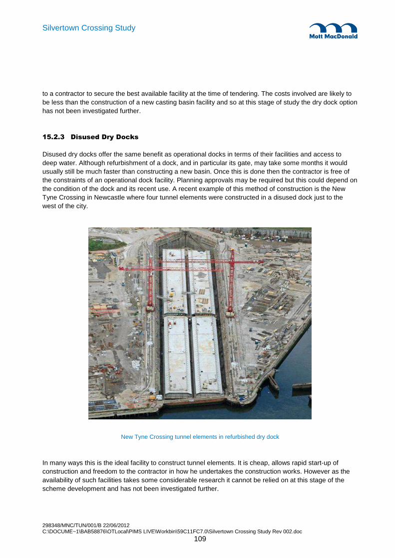
298348/MNC/TUN/001/B 22/06/2012 C:\DOCUME~1\BAB58876\OTLocal\PIMS LIVE\Workbin\59C11FC7.0\Silvertown Crossing Study Rev 002.doc
109
Silvertown Crossing Study
to a contractor to secure the best available facility at the time of tendering. The costs involved are likely to be less than the construction of a new casting basin facility and so at this stage of study the dry dock option has not been investigated further.
15.2.3 Disused Dry Docks
Disused dry docks offer the same benefit as operational docks in terms of their facilities and access to deep water. Although refurbishment of a dock, and in particular its gate, may take some months it would usually still be much faster than constructing a new basin. Once this is done then the contractor is free of the constraints of an operational dock facility. Planning approvals may be required but this could depend on the condition of the dock and its recent use. A recent example of this method of construction is the New Tyne Crossing in Newcastle where four tunnel elements were constructed in a disused dock just to the west of the city.
New Tyne Crossing tunnel elements in refurbished dry dock
In many ways this is the ideal facility to construct tunnel elements. It is cheap, allows rapid start-up of construction and freedom to the contractor in how he undertakes the construction works. However as the availability of such facilities takes some considerable research it cannot be relied on at this stage of the scheme development and has not been investigated further.

298348/MNC/TUN/001/B 22/06/2012 C:\DOCUME~1\BAB58876\OTLocal\PIMS LIVE\Workbin\59C11FC7.0\Silvertown Crossing Study Rev 002.doc
110
Silvertown Crossing Study
15.2.4 Use of Tunnel Approaches
Many immersed tunnels projects have utilised the tunnel approach areas as a temporary casting basin in which to construct the tunnel elements. Recent examples include the Medway tunnel and the Limerick tunnel. The benefits of this approach to construction are:
• Common worksite between tunnel elements and tunnel approach works is more efficient for contractor.
• Excavation is required in any case for the approach cut and cover tunnels, along with associated ground water cut-off measures or dewatering.
• Because the tunnel elements can be immersed in order, with the last element left in the entrance to the basin a mid-river closure joint can be avoided. (The closure joint is the insitu works that fills the gap left between the last two elements that are immersed). This reduces the amount of river construction operations and the disturbance to navigation.
This often makes good use of land made available for the construction and avoids the need to make arrangements with third parties.
Medway tunnel elements build on the line of the approach cut & cover tunnel

298348/MNC/TUN/001/B 22/06/2012 C:\DOCUME~1\BAB58876\OTLocal\PIMS LIVE\Workbin\59C11FC7.0\Silvertown Crossing Study Rev 002.doc
111
Silvertown Crossing Study
There are some issues to deal with as a result of deciding top use the tunnel approaches as a casting basin to build the elements.
• The cut and cover tunnel will not be constructed until after the immersed tunnel elements have been placed. This extends the construction programme over a scheme where elements were cast offsite and the cut and cover tunnels on both sides of the crossing were completed in advance of immersion.
• Excavation will usually be deeper than necessary for the approach cut and cover tunnels. This may mean partially filling the basin before the cut and cover section can be constructed. If piled foundations are needed these may need to be extended through any such fill.
This solution gives a high degree of certainty and at this early stage of project development and is therefore the basis on which the outline scheme has been developed. However, offsite casting options can be explored by contractors at a later stage to bring potentially large cost savings to the project. This is discussed further as part of the QRA in section 19.
15.2.5 Towing Elements from a Remote Site
If at a later stage an option to build tunnel elements remotely is found there will be some logistical problems to solve in regard to towing the tunnel elements to site. The general tow from the casting facility to the mouth of the Thames Estuary will be relatively straight forward but from there on the tow along the Thames will need to consider a series of staged tows. The Port of London Authority has noted the current speed of the Thames at ebb tide in the opposite direction to the tow will probably preclude towing at that time. Therefore towing will be carried out on the flood tide and then possibly within a restricted window that gives adequate water depth for the 9m draft of the tunnel element.
Within each stage of tow the element would have to be taken to a mooring with adequate water depth once the tide has gone out, or to a mooring where the tunnel element can be allowed to ground as the tide goes out. This would require a pre-prepared bed to ensure the element was landed in a controlled manner onto an even foundation, to avoid causing damage to the structure. Finding sites along the river to prepare such moorings will not be easy and may prove impossible. If that were the case the on-site casting of tunnel elements in the tunnel approaches would be the only viable option to pursue. This study has not investigated the possibility of temporary mooring sites along the Thames but this could be done at a later stage of scheme development.
298348/MNC/TUN/001/B 22/06/2012 C:\DOCUME~1\BAB58876\OTLocal\PIMS LIVE\Workbin\59C11FC7.0\Silvertown Crossing Study Rev 002.doc
112
Silvertown Crossing Study
15.3 Land Works
15.3.1 Greenwich Worksite
The Greenwich worksite will be used principally for the land based works of the cut and cover, approach ramp and ancillary buildings. It is possible that after placing of the immersed tube elements the principal civil engineering and M&E fit out activities will be serviced from Greenwich as the cut and cover construction will be continuing at Silvertown. The site logistics are therefore fairly standard in terms of providing support for d-wall construction and associated separation plant, and the excavation, propping and structural concrete works to the cut and cover boxes and ramps.
There are some extensive marine piling works at Greenwich with approximately 300 linear metres of piling probably using a combi pile wall or very heavy section piles or beams used as piles. Although the works are adjacent to and connect to the on-land works at Greenwich there is no requirement to load major items of plant onto marine craft at Greenwich and if necessary materials for the Greenwich marine works can be loaded onto marine plant off site or at Silvertown.
Constraints . The Greenwich site is constrained by the cable car but not to the extent that any of the cut and cover or ramp works require special plant or unusual construction methodologies. At the pylon the cable car is 80m above ground reducing to 50m above mid river. The slope down to the South Station at Greenwich does impose some height restrictions. The cable car pylon does have a significant effect on the marine works and it will be necessary to remove the cable car pylon protection to enable the construction of the necessary channel for the docking of the first immersed tube element with the Greenwich cut and cover box. During construction works the piling for the entry channel can incorporate protection to the pylon and on completion of the marine works the pylon protection can be reinstated.
The pylon foundations do not appear to be a physical obstacle to the works or the temporary works but as the project progresses there will need to be a demonstration that the pylon foundations are not affected by the works.
The safeguarded land appears to be adequate in extent although there is a narrow strip that allows very little working room around the cut and cover box. The land available is adequate to service the volume of construction activity.
Maintaining the existing road corridors does pose some problems. The principal access to the O2 area (Millennium Way) is cut by the works as is the north south link that serves the bus station. Millennium Way is a dual carriageway which appears to have adequate capacity and which can be cut to single carriageway with crossovers for the duration of the works. The cut and cover works beneath Millennium Way can be constructed beneath one carriageway at a time and the road reinstated once the appropriate section of cut and cover box is complete. There will be some temporary works required to uphold the carriageway that is in use adjacent to the excavation for the box. The other road that crosses the cut and cover box is a single carriageway and a temporary diversion will be required to enable construction of the cut and cover box beneath the road.
Access to the site . The site will be serviced by road. The Blackwall Tunnel Approach gives access to the primary road network. There will be major items of construction plant but they will not be dissimilar from the plant that has previously been used to construct the North Greenwich Jubilee Line Station Box.

298348/MNC/TUN/001/B 22/06/2012 C:\DOCUME~1\BAB58876\OTLocal\PIMS LIVE\Workbin\59C11FC7.0\Silvertown Crossing Study Rev 002.doc
113
Silvertown Crossing Study
The main volume of construction traffic will be spoil away and concrete and reinforcement coming in. There are nearby concrete batching plants that are river served for aggregates and that are only a short distance away by road. The volume of spoil to be removed may lead to consideration of removal by river but it is likely to be more practical to remove from North Greenwich by road.
Services. The electrical power demand will not be high. The major items of plant will be self powered diesel plant and no further consideration has been give to temporary power supply. Water and sewerage demand will not be unusual and again no further consideration has been given at this stage other than allowances in the costing.
Storage and workshop areas. The nature of the works does not require major storage areas. However a bentonite separation plant will be required for the diaphragm wall operations. It may also be necessary to classify spoil for removal as waste so there may need to be stockpiling of spoil on site to enable efficient classification prior to disposal.
There will need to be an area for shutter preparation and maintenance and there may be a need to consider reinforcement fabrication. However, rather than prefabricating reinforcement it is more likely that investment will be made in setting up the reinforcement in situ in such a way that maximum in situ productivity can be achieved by the optimising of stages and location of lay downs and the covering of the location where fixing is taking place.
Batching concrete on site is something that a contractor will consider but it is not a fundamental requirement arising from the nature of the work, so concrete is likely to be supplied from nearby ready mix plants with facilities to receive aggregate by river transport.
Offices and welfare facilities. The Greenwich site is a significant construction site but it is likely to be considered as a subproject with the main project offices at Silvertown. In addition to the land based work it may be used by some of the staff involved in the marine works but plant and materials for these works will not generally be handled at Greenwich.
15.3.2 Construction of Cut & Cover Tunnels - Greenwich
The cut and cover box construction will generally be carried out using D-walls to provide the horizontal ground support in the permanent and temporary case. D-wall construction is preceded by guide wall/trench construction which also acts at shallow depth to ensure pre-clearance of obstacles. Further site investigation information may suggest a change to secant pile walls in some locations but this is not a fundamental change to the design concept. The cut and cover box will probably be constructed bottom up with temporary props until the base slab and top slab are in place. It may be possible to construct it top down with the permanent roof providing the highest level of strutting in both the temporary and permanent case. Excavation below the top slab would need to be carefully planned to maintain access and would require selection of plant to suit the low headroom as temporary props are likely to be required above the base slab until the permanent base is in place. The decision to construct bottom up or top down is a decision that will be made once the contract is placed and will be greatly influenced by the detailed ground conditions and the number of obstructions that need to be accommodated along the line of the cut and cover box. Bottom-up is likely to offer greater programme flexibility.
298348/MNC/TUN/001/B 22/06/2012 C:\DOCUME~1\BAB58876\OTLocal\PIMS LIVE\Workbin\59C11FC7.0\Silvertown Crossing Study Rev 002.doc
114
Silvertown Crossing Study
With the base slab and top slabs cast the structure is effectively complete but will need finishing works including drainage channels and screen walls prior to be ready for road works and M&E works.
The open ramp will use similar plant and a simplified construction methodology with only the deeper sections of ramp requiring temporary propping ahead of base slab construction.
As noted, the Greenwich ramp and box may form the logistics access to the immersed tube once the elements are placed due to the ongoing cut and cover works at Silvertown. This means that many of the activities will commence at the Silvertown end of the immersed tube with logistical support from Greenwich with the works generally working back towards Greenwich.
15.3.3 Silvertown Approach Worksite
Constraints . The cable car pylons are a nuisance that will require exclusion areas but clearance to the cable car itself is not a problem. There is 80metres of clearance adjacent to the pylon. The proximity to the DLR viaduct just adds to the restrictions of working beneath the DLR and maintaining access to the casting basin.
The DLR viaduct is a serious problem that has a significant effect on construction beneath the viaduct and has a significant effect on the site layout. The effect on construction methodology will be considered separately. The effect on access is that it is a height problem and a routing problem. As far as access is concerned the height will restrict plant movements on site and the structure will need to be protected by goal posts at authorised cross under points with barriers elsewhere to prevent the use of unauthorised cross under points.
There are stages during the works when two access routes are required to the casting basin from the rest of the site so that when one route is blocked by construction activity on the cut and cover box, the other route can be used. The site layout accommodates two routes although at times it will be necessary to go round the cut and cover and ramp works and travel along the north side to get from the river at Thames Wharf to the casting basin.
The headroom clearance under the DLR can be increased if necessary by local ground lowering although this will require assessment of the DLR viaduct foundations to ensure that any ground lowering has no adverse impact on the foundations.
There is also a drain associated with the Royal Docks and this drain will need protection and diversion to facilitate the progress of the works and the development of the temporary site infrastructure. This work is not shown on the programme although it should be possible to accommodate it once details of the dock drain and the form of replacement are known. It is considered as a line item in the cost plan. It would be worth considering carrying out any necessary work to the dock drain as advance enabling works let as a separate contract ahead of the main works.
Access to the site. Access to the site will be available by road from the principal road network. However to minimise road movements construction spoil can be removed by ship and aggregate and fill can be delivered by barge. There will be a number items of construction plant (particularly D-wall plant and piling plant) that will be abnormal loads but nothing that is unusual on major projects in London that are served by road.

298348/MNC/TUN/001/B 22/06/2012 C:\DOCUME~1\BAB58876\OTLocal\PIMS LIVE\Workbin\59C11FC7.0\Silvertown Crossing Study Rev 002.doc
115
Silvertown Crossing Study
Power supply & other services. The majority of the heavy construction plant will be diesel powered but there is likely to be a concrete batching plant which is electrically powered as well as a range of ancillary plant and pumping plant. The electrical power demand will be far less than the power demand for a TBM and although no specific enquiries have been made of electricity suppliers it is known that the necessary power supply will exist by virtue of the Crossrail works which require the simultaneous driving of three TBMs from nearby Limmo.
Water and sewerage demand will be higher than at Greenwich but for this study no further consideration has been made other than an allowance in the costing.
Storage and workshop areas. There will need to be undercover storage for some specialist materials such as seals which are needed as part of the immersed element construction. There will need to be lay down areas for reinforcement and temporary structural steel. There will need to be workshops for temporary works fabrications and for plant maintenance. This is not the major plant items but the multitude of smaller items such as pumps, concrete vibrators and on site vehicles used for site haulage.
Offices and welfare. It is envisaged that the main project offices will be at Silvertown and that the majority of the welfare facilities will be at Silvertown to satisfy the labour needs of the land based works at Silvertown and most of the marine works. The area nearest the road access and furthest from the works themselves has been allocated for offices and welfare.
Batching plant. It may be possible to manage without a site batching plant but the certainty of supply and ability to control quality and to react to programme requirements means that a site batching plant is the first choice. Contractors tend to subcontract the establishment of the batching plant on site and the supply of concrete to a ready mix company who then manage the process. This gives the combined benefit of the concrete supply expertise of the ready mix company and the dedicated supply that is needed for a major project. At the time of construction contractors will test the market and may reach an agreement to take concrete from the local ready mix market but for planning purposes it is sensible to assume on site batching. For planning it is assumed that aggregate will be delivered by barge to the site rather than by road.
Stockpile areas. It is assumed that spoil will be removed from site by ship and that therefore a route through the site from the casting basin to the wharf will be maintained at all times. The spoil will be generated on a continuous basis during the working day and will be loaded to suit tides and therefore an onsite stockpile will be needed convenient to the wharf. Actual loading of ships will probably be by ship loading conveyor fed from a bunker which can be fed directly by tipping from dump trucks or by front loader from a stockpile.
Rebar storage/fabrication area. There will need to be a rebar storage area. If on site pre- fabrication is worthwhile this will be adjacent to or combined with the storage area. The decision on fabrication will be a contractor decision. There are so many straight bars that off site fabrication is unlikely to be economic, on site fabrication may be possible but introduces additional craneage demands and possibly the final choice will be principally to fabricate in situ but to turn that into a well supported factory type process.

298348/MNC/TUN/001/B 22/06/2012 C:\DOCUME~1\BAB58876\OTLocal\PIMS LIVE\Workbin\59C11FC7.0\Silvertown Crossing Study Rev 002.doc
116
Silvertown Crossing Study
15.3.4 Construction of Cut & Cover Tunnels - Silvertown
The cut and cover tunnels and approach ramp at Silvertown would be relatively straight forward if it were not for a number of complications. The cut and cover structure obstructs access to the casting basin, some of the work must be carried out beneath the DLR and some of the work is in the casting basing and can only be completed once the casting basin has been emptied following float out of the tunnel elements.
The complication with the section of the cut and cover in the casting basin is principally one of programme rather than method although there will be a need to place and compact fill prior to commencing construction of the cut and cover within the former casting basin.
The need to maintain access from the casting basin to the wharf, to the external roads and to the batching plant at the appropriate time is a constraint on the construction of the cut and cover. The D-walls can be constructed working on a relatively short stretch at a time and once a D-wall panel is constructed a site road can run over it. There will therefore need to be some careful planning and phasing of the D-wall works to enable good access to be maintained to the casting basin at all times, but it should be possible.
Following D-wall construction it is likely that the cut and cover box will be completed bottom up with temporary props to maintain stability during construction prior to placing base and roof slabs. This could be done in relatively short lengths to allow a site road to operate nearby and then allow the site traffic to switch over the newly finished box with suitable protection. With some relatively minor temporary works to uphold the edges of excavations it should be possible to complete the majority of the cut and cover outside the casting basin in parallel with the preparation of the casting basin and construction of the immersed tube elements.
The real complication is the DLR. The headroom is nominally about 5m which is not likely to be sufficient for a secant piling rig of sufficient torque capacity or sufficient for a low height D-wall rig. It should be possible to do some limited ground lowering without getting down below the water table and then establishing a piling platform at a lower level to generate sufficient clearance. It is anticipated that a solution can be developed in this area that will have not detrimental impact to the existing DLR structures. The final design and the construction methods will need to be approved by DLR through an AIP process. This solution impinges on the previously described problem of maintaining access through the site at all times. However with the benefit of temporary works to uphold excavations and careful scheduling it should be possible to overcome these problems together.
Apart from these issues the remainder of the cut and cover works at Silvertown outside the casting basin are essentially the same tasks as described at Greenwich.
15.3.5 Casting Basin Worksite
The safeguarded area to the east of the cable car on the Silvertown approach has been chosen for a casting basin location. It offers a number of benefits:
• The land is available.
• A layer of London Clay exists below the level of the casting basin base that will enable an effective ground water cut-off to be achieved and avoid the need for dewatering to lower the ground water table. Beneath the London Clay are the Lambeth beds which are also cohesive in nature.
• Reasonable road access is available to the basin site through the main Silvertown worksite access.

298348/MNC/TUN/001/B 22/06/2012 C:\DOCUME~1\BAB58876\OTLocal\PIMS LIVE\Workbin\59C11FC7.0\Silvertown Crossing Study Rev 002.doc
117
Silvertown Crossing Study
• Utilising the area of the approach for the basin, which has to be excavated in any case is economic.
• Towing elements along the Thames is avoided.
• A mid-river closure joint construction is avoided.
The site offers only just sufficient area for the basin. It will therefore be formed using a combination of earthworks slopes and combi-pile walls around the perimeter. Retaining walls will be anchored where necessary using walings and ground anchors penetrating into the London Clay.
The western side of the basin will be formed by an earthworks slope. Within the slope an access ramp down into the basin will be formed. This may require minor retaining works using sheet piles. The remainder of the basin perimeter will be formed with a combination of earthworks and retaining walls formed with combi-piles. Retained heights will vary between 8m and 18m and walls will be anchored with ground anchors down into the London Clay. The taller walls will have two rows of anchors with waling beams and the shorter walls a single row of anchors.
The steel tubes forming the walls will be driven. If it is not possible to drive them through hard layers then augering may be needed or the use of chisel may be necessary in extreme cases.
Care will need to be taken in the design of the temporary works in the area of the cable car north tower to ensure there is no impact on tower foundation. The combi-pile walls offer a stiff structure and combined with ground anchors will create a wall which should suffer from very little deflection. However there is a degree of movement with every form of retaining structure and the impact the movement may have on the tower foundation piles will need to be assessed in detail to arrive a solution that has no detrimental impact.
Where there are earthworks slopes that are below the MHWL their surface will be treated to make them impermeable, either with a layer of clay material arising from the excavation or with a membrane to ensure the basin can be flooded without loss of water to the surrounding ground. The base of the basin will be provided with a 750mm thick layer of coarse gravel. This will enable the curved profile of the underside of the tunnel to be formed and ensure that water can percolate beneath the tunnel elements and allow float-up.
It is not anticipated that the basin will need any foundation or ground improvement. The London Clay will provide a stiff foundation support to the tunnel elements during their construction. There is one corner of the basin where the clay appears to thin. This is in the area of the basin entrance. There is a risk that ground water cut-off is not as easy to achieve in this area and a degree of sump pumping may be required. These assumptions will need to be evaluated in a subsequent stage of feasibility study.
At the entrance to the basin a deeper zone is to be excavated beneath the southernmost tunnel element. This will allow an element to be floated and moved out of the basin at any tidal condition, which is an advantage to the marine works contractor as it does not constraint activities within the period programmed for warping out tunnel elements and immersing them. Also, just behind the basin entrance a short section of the cut and cover base slab will be constructed to enable the last tunnel element to be braced in position. This is at a depth that allows the tunnel elements to pass over it and to suit the final tunnel alignment.
As mentioned above a ramp access will be provided on the west side for site plant and vehicles. Sufficient space has been allowed between the tunnel elements to ensure cranes, trucks and site vehicles can pass between them. It is assumed that any prefabrication of reinforcement panels will be carried out at a high
298348/MNC/TUN/001/B 22/06/2012 C:\DOCUME~1\BAB58876\OTLocal\PIMS LIVE\Workbin\59C11FC7.0\Silvertown Crossing Study Rev 002.doc
118
Silvertown Crossing Study
level and the panels transported down into the basin for assembly. However there is no real need to allow for major prefabricating activities.
Craneage - The requirement for craneage in the casting basin is principally the need to handle bundles of reinforcement and the need to erect and possibly to move shutters and to move small items of plant. Concrete will be pumped. Ideally the craneage would give coverage of the whole of the casting basin with an adequate capacity at all points. Crawler mounted cranes or other mobile cranes outside the basin will not work. Too much of the perimeter is inaccessible and the batter increases the radius at which cranes will need to operate. Tower cranes at strategic points inside the basin will not work. There are too many restrictions to the free use of the crane and for cranes to reach all points within the basin and to have a useful lifting capacity will require 5 of the largest cranes on the market.
Gantry cranes have been considered but the temporary works cost of providing crane rails and the cost of the bespoke cranes all but eliminates gantry cranes.
The craneage demand is not great so a very low key solution is proposed. An access ramp is provided down into the basin and there is a nominal 5m between units inside the basin. A mobile crane can therefore pass between units at basin floor level. This helps when only the base slabs are under construction but once any wall shutters are in place a crane at the basin bottom level is restricted in what it can reach.
The planning is based on rough terrain mobile cranes which can operate on the basin floor but can also operate on the base pour of any unit that is under construction once the base has been poured. This tends to restrict the work on a particular immersed tube element to a linear type operation which reduces overall programme flexibility. There can if necessary be two linear operations on each unit if the wall and roof pours are commenced from the centre of each unit but the programme does not demand that. With four units that can be constructed virtually in parallel there should be enough flexibility to service each element and maintain production efficiency.
15.3.6 Construction of Tunnel Elements
There is no need for a detailed sequence of construction at this stage as the programme time and flexibility of approach mean that the programme is driven by overall production rates and resources rather than by the need to follow a prescriptive sequence. The elements will be constructed as 5 or 6 segments per element with each segment between 20 to 25 metres long. Simple match-cast debonded joints with cast-in waterstops will be formed between the segments.
Formation will be created in the gravel layer placed in the bottom of the basin excavation. Curvature for the vertical alignment will be created as a series of planes forming chords along the vertical curve, one plane being the length of a tunnel segment. The gravel will be blinded with porous no-fines concrete to allow water percolation through to the underside of the tunnel when the basin is flooded.
The bases will be constructed first, probably working from the end of the basin furthest from the access ramp back to the access ramp. When one of the bases has advanced by a number of pours the wall shutters will be erected. The walls and soffits could be constructed as a single pour for each bay using three travelling shutters to form the two road spaces and the central gallery. A probable alternative would be to form the inner walls and then to use two travelling shutters for the outer wall and the roof. Allowance has been made for purpose built shutters for each element to allow working on four elements at any time

298348/MNC/TUN/001/B 22/06/2012 C:\DOCUME~1\BAB58876\OTLocal\PIMS LIVE\Workbin\59C11FC7.0\Silvertown Crossing Study Rev 002.doc
119
Silvertown Crossing Study
It is anticipated that all four elements will be worked effectively in parallel with around one month’s lag so that resources can be deployed on multiple fronts to provide good labour continuity and good plant utilisation. The one month stagger between completion of the concrete works to the elements then allows one month per element to ready it for handover to the specialist subcontractor for float out.
The form of construction requires watertight concrete to be produced and each wall and roof pour will contain cast-in pipework through which chilled water is passed to control the concrete temperatures during the critical first 2-3 days of curing. There will be monitoring of poured concrete using thermocouples to measure temperature and to allow maturity to be calculated and to inform decisions on when to cease cooling each pour. A small mobile chiller unit with control station will be positioned in the casting basin to service the concrete pours.
Steel end frames will be cast into the ends of each tunnel element in order to mount the Gina gasket required for the immersion process. The I-section frame will be lifted in pieces into the formworks where it will be welded insitu. After casting of the concrete a counterplate will be welded in between the flanges to high accuracy and the void behind grouted. After carrying out any repairs to paintwork the Gina gasket will then be lifted in and clamped to the counterplate. Temporary protective boxes will be placed around the Gina gasket to protect it during the floating and warping of tunnel elements.
Other fitting out works that will be required before floating the elements include the building of ballast tanks within the elements, fitting ballast pipework, the temporary prestressing of the elements including grouting of the ducts, grouting of the segment joint injectible waterstops and mounting of bollards and an access shaft on the roof of the tunnel element.
Ahead of flooding the basin the ballast tanks will be filled and checked to ensure they are leak free and the ballast pumping systems are operational. With the ballast tanks full the basin can then be cleared of temporary plant, equipment and materials and then flooded ready for the floating and immersion process to begin.
15.4 River Works
There are a number of other operations required in the River Thames to construct the immersed tunnel:
• Installing cofferdams
• Installing protective works to the Cable Car
• Dredging
• Immersing tunnel elements
• Backfilling
Each of these is addressed in turn to explain the nature of the works so that the impact they may have, either on the users of the river or the surrounding environment, may be understood.
298348/MNC/TUN/001/B 22/06/2012 C:\DOCUME~1\BAB58876\OTLocal\PIMS LIVE\Workbin\59C11FC7.0\Silvertown Crossing Study Rev 002.doc
120
Silvertown Crossing Study
15.4.1 Installing Cofferdams
At Greenwich it is necessary to connect the first immersed tube element to the Greenwich side cut and cover box that is constructed in advance. The ground at the end of the cut and cover box will need to be supported and this will be done with a pile wall – probably combi-piles because of the heavy duty and these pile will wrap around the D-walls and allow the remainder of the cut and cover box to be constructed independently of further piling or marine works.
With the piling at the end of the box complete the piling will be extended towards the river wall and sealed against the river wall clear of the point at which the river wall will be broken through. The river wall will then be broken out and the combi-piles will continue out into the river. All these works could be carried out as land based works or could be done as marine works.
With the line of combi-piles extending into the river, the piling operation will change from a land based operation to a marine operation to continue the combi-pile wall out through the foreshore into the river. There will be a return on the combi-piles to bring them parallel to the river wall and to allow the main dredging in the river to be carried out to the open cut profile without undermining the river wall. The sequence of major activities is shown on drawing MMD-29348-TUN-311.
The temporary piled wall is required to perform a very heavy duty and therefore is likely to be formed using steel tubular piles with standard sheet piles welded to each side to enable them to be clutched together like sheet piles but to form a much stronger wall that sheet piles alone. There are other forms of high modulus pile including the use of steel beams with crimped flanges that are then connected to form a continuous wall. The final form of the temporary works will depend on the engineering requirement and market conditions at the time but whatever the form of wall the installation methodology will change only in detail.
The duty that the combi-pile wall performs varies, but in places it is required to retain a full height of ground on one side with air on the other side. In the river it is required to retain the foreshore on one side with the river at lowest tide on the other. It is also required to be able to prevent any lateral movement having an adverse effect on the cable car pylon foundations.
The traditional approach for installation would be to use a diesel hammer and leaders, but it is probable that a more modern approach which uses the reaction of adjacent piles and a jacking and vibrating system will be effective. This requires a panel of piles to be set up in a gate or frame, toed in to achieve temporary stability and then jacked in. This will require large crawler cranes to handle and pitch the piles and a large crane to handle the pile driving equipment. There is nothing special about the cranes other than their size.
When the piling is out of reach of land based cranes it will become a marine operation, using floating plant probably with jack legs but it will still require large cranes and use the same piling rigs. A temporary jetty for construction plant may be an alternative idea that a contractor would consider.
These works will cut across the line of the cable car pylon protection which will have to be removed. The combi-pile return will temporarily provide the necessary ship protection to the cable car pylon and on completion of the works the temporary combi pile wall will be removed and the ship protection reinstated.
The removal of combi pile walls is effectively the reverse of installation. There will be an early removal to enable float in of the first immersed tube element with all piles being removed on completion of the backfill to the immersed tube at the Greenwich side and the reinstatement of the river wall.

298348/MNC/TUN/001/B 22/06/2012 C:\DOCUME~1\BAB58876\OTLocal\PIMS LIVE\Workbin\59C11FC7.0\Silvertown Crossing Study Rev 002.doc
121
Silvertown Crossing Study
At Silvertown the piling methodology will be the same although the detail layout will be different because the river wall is a tied sheet piled structure and the foreshore is much narrower and therefore requires a lesser extent of protection. The piles form a temporary exit structure to the casting basin and provide protection to the river wall and reduce the disturbance of the foreshore to the minimum. Although only 15m out into the river, it is likely that all this work will be done entirely as a marine operation.
The piles that form the entrance to the casting basin will be removed prior to float out and with the final immersed tube element in position a temporary connection will be made between the combi pile wall and the sides of the element to allow the casting basin to be emptied.
The remainder of the piles will be removed once the cut and cover section is complete adjacent to the last immersed tube element and the river wall has been reinstated
Typical combi-pile walls forming cofferdams through river walls are shown below;
Typical cofferdams at river wall for an immersed tunnel

298348/MNC/TUN/001/B 22/06/2012 C:\DOCUME~1\BAB58876\OTLocal\PIMS LIVE\Workbin\59C11FC7.0\Silvertown Crossing Study Rev 002.doc
122
Silvertown Crossing Study
15.4.2 Protection to Cable Car
The south tower of the cable car is founded in the river with a pile cap at approximately low water level. The piles to the tower are believed to extend to depth into the Thanet sands and possible the underlying chalk formation below. The tunnel alignment passes immediately east of the foundation.
The tower must be protected from possible ground movement from the construction works and from any plant used in construction. As the ship impact barrier will need to be dismantled temporarily during construction it is essential that an equivalent level of protection is provided for in the temporary works.
Ground movement - A temporary cofferdam will be constructed along the edge of the immersed tunnel alignment to the east of the tower foundation and return around the north side of the foundation along the low water line. This will provide a boundary for the dredging works which is well outside of the exclusion area for the foundations identified on the drawings. The cofferdam will be a stiff combi-wall structure formed from large diameter interlocking steel pipes. These are driven to depth and will be embedded approximately 5m below the depth of dredging that is required.
Dredging will create a step in level either side of the wall causing lateral load to come onto the rear of the wall. This can result in rotation of the wall and flexure of the wall and both of these effects could cause lateral ground movements. They must therefore be controlled in order to ensure there is no impact to the tower foundation. If lateral ground movements were allowed to occur then the tower piles could follow the ground and incline, resulting in an inclination of the tower.
Flexure of the wall is controlled by the stiffness of the wall structure. Although there will be a step in ground level to either side of the wall the wall will always have water on both sides of it so the loading is not that great for a wall of this type. The stiffness of the wall using 1200mm diameter steel pipes will be adequate to prevent any significant flexure from occurring.
Rotation of the wall will be controlled by propping the top of the wall, which is above the water line, across to the opposite side of the cofferdam. The opposite wall is subject to the same loading in the opposite direction so the act of propping the structure prevents rotation from occurring. The only movements that occur will be the result of elastic deformation due to the load in the prop and this will be a very small deformation.
In addition to the control measures described the distance separating the combi-pile wall from the foundation should be considered. The potential lateral ground movements decrease significantly with distance from the wall. The spacing of 20m already goes a long way to mitigating the influence on the tower foundation. However it is still within the zone of influence and so at the next stage of scheme development it would be necessary to set up an analytical model for the foundation and wall and determine the precise movements that might occur and ensure they are suitably controlled. This would allow third party approvals of the proposals to be sought.
Settlement of the tower foundations is not considered to be a problem because the piles supporting the tower extend below the depth of the tunnel. For the immersed tub there is generally a net unloading effect because the weight of the tunnel and fill is often less than the weight of soil that has been removed. This may cause small amount of heave in the London Clay layer but the movements will be small and localised to the base of the trench and so this is not considered to pose a significant risk to the tower.

298348/MNC/TUN/001/B 22/06/2012 C:\DOCUME~1\BAB58876\OTLocal\PIMS LIVE\Workbin\59C11FC7.0\Silvertown Crossing Study Rev 002.doc
123
Silvertown Crossing Study
Impact protection - The current impact protection to the tower is provided by a group of three dolphin structures. A central floating dolphin in located approximately 20m further offshore from the tower foundation and two fixed restraint dolphins which are located on the foreshores to either side of the tower. A tubular steel floating boom on a tensioned arrestor cable spans between the floating dolphin and fixed dolphins on either side. The east leg of this protection will need to be dismantled in order to construct the immersed tunnel. This only requires the tension cable system and floating boom to be removed provided the plant for installing the cofferdam combi-piles can work around the dolphin structures.
The propped cofferdam to the east of the tower will provide an equivalent level of protection from impact from vessels. The cofferdam extends above the waterline and if necessary a capping beam or fendering beam can be fixed to the top of the wall to prevent any sharp impacts to a vessel colliding with it.
The sequence of cofferdam installation and dismantling of the tower impact protection must be considered to ensure there in no significant period where the structure may be left at risk. It will be necessary to dismantle the impact protection ahead of installing the northern end of the cofferdam so a temporary alternative impact protection may be required. However, whilst the jack-up platform on in position for the piling work this will effectively prevent any impact from occurring.
15.4.3 Dredging
The principle of avoiding dredging of the foreshore areas has been followed to protect these environmentally sensitive zones and temporary combi-pile walls will be installed for this purpose. These extend through the foreshore and have wing walls that return along the low water line to ensure the dredging works is confined to the channel.
The material to be dredged is relatively stable and will allow quite steep slopes to be cut by the dredger. The volume of dredged material is as follows;
• Alluvium 15,000m³
• Thant sands and terrace gravels 50,000m³
• London Clay & Lambeth Group 200,000m³
Materials re-use is unlikely as the bulk of the material is London Clay and this will need to be treated as waste and be disposed of. The small volumes of sands and gravels would need treating and stockpiling, cleaning and grading to be re-used and this is unlikely to be cost effective.
Contamination of the alluvium is possible. This is discussed later in the environmental appraisal. Sampling and analysis will be necessary as part of the licensing requirements in order to identify any contaminated material and to arrange for suitable disposal. An assumption has been made for the purposes of costing that 25% of the top 1.0m of material will be contaminated. This gives rise to a volume of approximately 8000 m³ for disposal as contaminated waste.
For material that is found to be non-contaminated, a small Water Injection Dredger (WID) can be utilised to dredge the alluvium at the surface of the river bed. The dredger would operate during ebb tide periods only. The proposed plant is highly manoeuvrable and will have a minimal impact on navigation by other river users.

298348/MNC/TUN/001/B 22/06/2012 C:\DOCUME~1\BAB58876\OTLocal\PIMS LIVE\Workbin\59C11FC7.0\Silvertown Crossing Study Rev 002.doc
124
Silvertown Crossing Study
Typical WID dredger
To dredge within the cofferdam structures and operate below the props, a small cutter suction dredger with extremely low air draught could be used.
Low headroom cutter suction dredger
This type of dredger operates with side wires rather than spuds. The dredged material would be loaded into a large sea going split barge for disposal at the South Falls Disposal site in the outer Thames Estuary. The material would be loaded via a floating pipeline and a multicat would be used to attend to the pipeline. The dredger would be remotely operated and apart from maintenance does not require personnel to be onboard while it is working. Operations would be remotely controlled from a nearby small pontoon. The barge would be one of the large barges that would later on work with the backacter dredger during the main excavation. Again this proposed plant is highly manoeuvrable and will have a minimal impact on navigation by other river users.
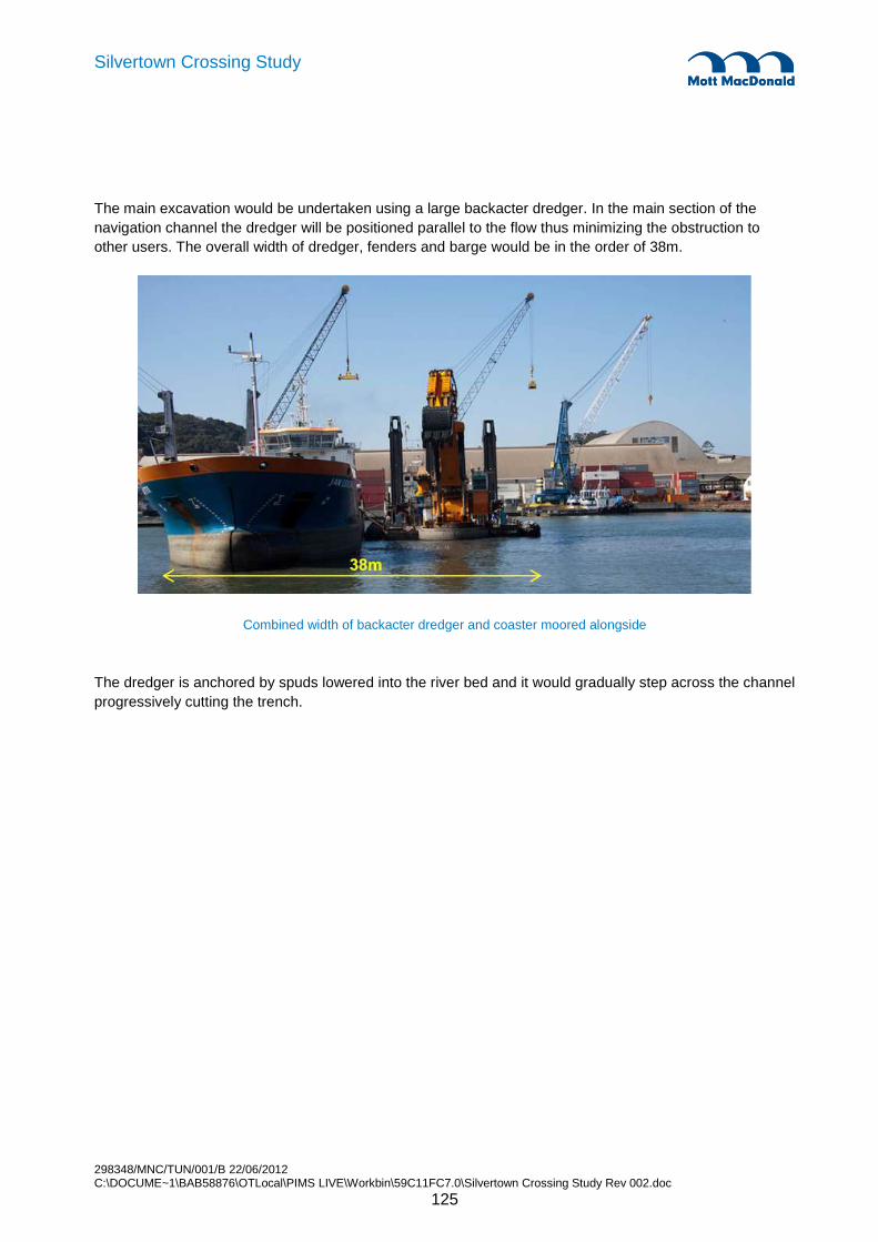
298348/MNC/TUN/001/B 22/06/2012 C:\DOCUME~1\BAB58876\OTLocal\PIMS LIVE\Workbin\59C11FC7.0\Silvertown Crossing Study Rev 002.doc
125
Silvertown Crossing Study
The main excavation would be undertaken using a large backacter dredger. In the main section of the navigation channel the dredger will be positioned parallel to the flow thus minimizing the obstruction to other users. The overall width of dredger, fenders and barge would be in the order of 38m.
Combined width of backacter dredger and coaster moored alongside
The dredger is anchored by spuds lowered into the river bed and it would gradually step across the channel progressively cutting the trench.

298348/MNC/TUN/001/B 22/06/2012 C:\DOCUME~1\BAB58876\OTLocal\PIMS LIVE\Workbin\59C11FC7.0\Silvertown Crossing Study Rev 002.doc
126
Silvertown Crossing Study
Working pattern for backhoe dredger and coaster moving along tunnel trench
After the trench has been dug, it will have to remain open for a period of time. It is likely that during this period the trench will attract some build up of material that is being transported through the estuary, most likely silts. Maintenance of the open trench during this period would be carried out using a large Water Injection Dredger that is capable of bringing the deposited silts back into the natural system by injecting water into them. After the water injection the silts will travel down stream as they would have if no trench were there to deposit in.

298348/MNC/TUN/001/B 22/06/2012 C:\DOCUME~1\BAB58876\OTLocal\PIMS LIVE\Workbin\59C11FC7.0\Silvertown Crossing Study Rev 002.doc
127
Silvertown Crossing Study
WID dredger for maintenance
Dealing with Obstructions - For the main dredging works there are risks of encountering hard obstructions, either man-made such as old piles in the river, or natural obstructions such as pieces of hard material in the Blackheath beds (Harwich formation). This material occurs occasionally at the interface between the London clay and Woolwich and reading beds (Lambeth group) and so may be encountered during dredging work. If this is not possible to break with the backhoe then specialist equipment may need to be brought in to deal with this. Additional marine ground investigation would be necessary at a later stage to get a fuller understanding of the risk of this arising.
Unexploded ordnance in the River is another risk for the dredging operation. Advance surveys can be extremely useful in identifying any larger metallic objects buried in the upper layers of the river bed. A watching brief will be needed during the dredging operation however, for the surface layers to look out for small items that may not be detected by survey. Although this represents a risk the procedures are well developed and understood so that the real risk to construction workers and the public can be minimised.
Logistical planning - A large volume of material will be removed from the river by the dredging operation. This will need to be transferred by barge of coaster down the river to a licensed disposal site. Due to the strong currents that are present at times in the river, barge movements and shipping movements tend to be planned to suit the tidal regime so that vessels use the flood and ebb tides for leaving and entering the city respectively. This reduces the daily window for barge movements. Dredging will continue 24 hours if permitted which may ease coordination to a degree but close coordination with other shipping movements will be required, particularly the regular daily barges carrying waste from the city and any specific project related movements such as materials arising from Thames Tideway project if it happens to be running concurrently.

298348/MNC/TUN/001/B 22/06/2012 C:\DOCUME~1\BAB58876\OTLocal\PIMS LIVE\Workbin\59C11FC7.0\Silvertown Crossing Study Rev 002.doc
128
Silvertown Crossing Study
Environmental issues - The environmental issues associated with dredging must not be overlooked. These are dealt with in detail in the preliminary environmental appraisal but the main points of concern are:
• Spill control and hence controlling turbidity during agitation dredging of alluvium, bulk dredging and maintenance dredging;
• Dredging during winter season to avoid fish migrations;
• Loss of marine habitat;
• Licensed disposal of contaminated materials and non-contaminated materials
These issues will need to be addressed to the satisfaction of the Environment Agency and PLA. This process has been followed and agreement has been achieved previously in the UK for immersed tunnel projects at Conwy, Medway and more recently for the New Tyne Crossing in Newcastle. The Conwy estuary and the River Tyne both have sensitive marine ecologies featuring important fish migrations at specific times of the year. Strict limits on the concentrations of suspended sediments and oxygen levels ion the water were set and adhered to. Often immersed tunnel schemes are dismissed quickly because of concerns in this regard but these two examples show that water quality can be maintained through simple measures.
The dredging work will cause a temporary loss of habitat in the foreshore mudflats. Agreement must be reached with the EA as to whether this can be accepted and what level of compensatory habitat should be established during the period it takes to construct the tunnel and for the habitat to re-establish itself above the tunnel.
15.4.4 Tunnel Element Immersion
A number of specialist pieces of floating plant and temporary works equipment are required to float, manoeuvre and immersed tunnel elements. A specialist marine contractor with experience of this type of work is also needed. In preparing this part of the report assistance has been provided by Strukton Mergor of the Netherlands who have undertaken such works on numerous immersed tunnel projects around the world.
The tunnel crossing at Silvertown is a relatively conventional immersed tunnel and does not require methods or equipment that has not already been tried and tested on other projects. The main pieces of floating plant that will be required are:
• 2 no. catamaran pontoons that will be used for each tunnel element. tThese are used to lower the tunnel elements into position into the dredged trench
• 2 no. anchor platforms with 2 no. river bed anchorages. There are used to anchor the tunnel element and catamaran pontoons to control their lateral position.
In addition there will be a number of small craft required to undertake the works such as multi-purpose vessels for handling winch cables and equipment and work boats for personnel.
Facilities will be established around the casting basin for the immersion operations. These will include pumping equipment for flooding and dewatering of the basin including pumps, pipework or sluices to enable the flooding or dewatering operation to take place in a period of approximately 2 days. Mooring
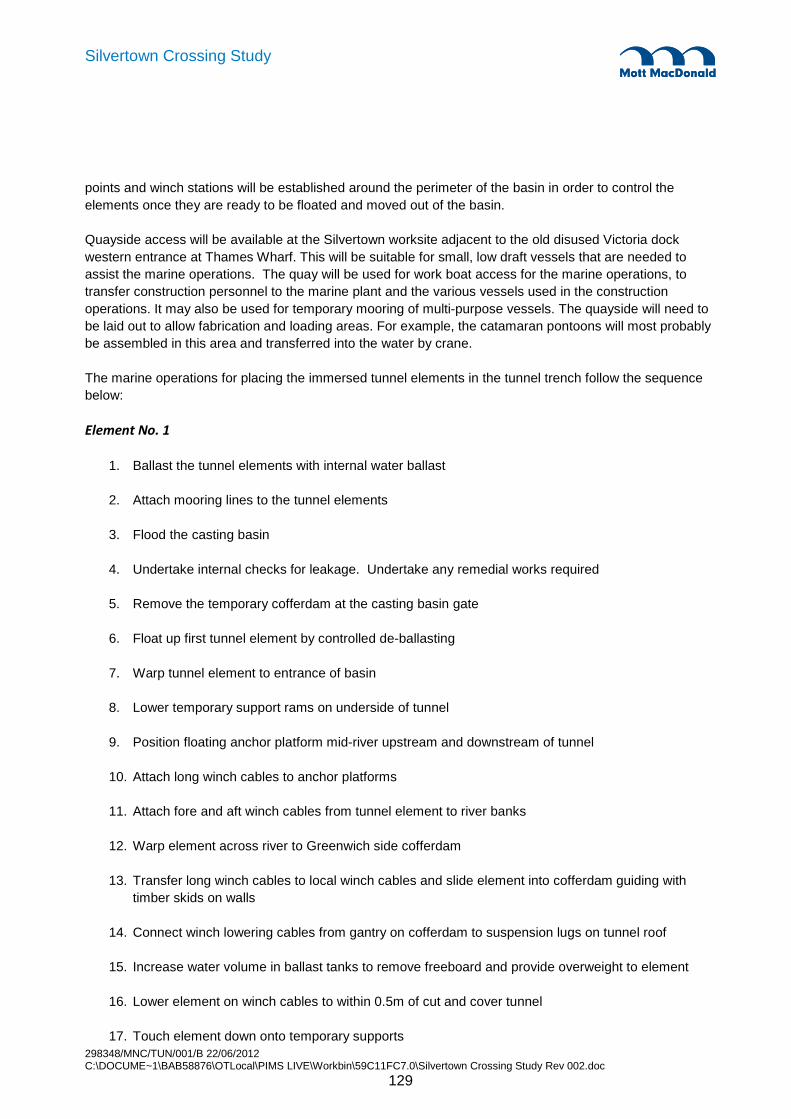
298348/MNC/TUN/001/B 22/06/2012 C:\DOCUME~1\BAB58876\OTLocal\PIMS LIVE\Workbin\59C11FC7.0\Silvertown Crossing Study Rev 002.doc
129
Silvertown Crossing Study
points and winch stations will be established around the perimeter of the basin in order to control the elements once they are ready to be floated and moved out of the basin.
Quayside access will be available at the Silvertown worksite adjacent to the old disused Victoria dock western entrance at Thames Wharf. This will be suitable for small, low draft vessels that are needed to assist the marine operations. The quay will be used for work boat access for the marine operations, to transfer construction personnel to the marine plant and the various vessels used in the construction operations. It may also be used for temporary mooring of multi-purpose vessels. The quayside will need to be laid out to allow fabrication and loading areas. For example, the catamaran pontoons will most probably be assembled in this area and transferred into the water by crane.
The marine operations for placing the immersed tunnel elements in the tunnel trench follow the sequence below:
Element No. 1
1. Ballast the tunnel elements with internal water ballast
2. Attach mooring lines to the tunnel elements
3. Flood the casting basin
4. Undertake internal checks for leakage. Undertake any remedial works required
5. Remove the temporary cofferdam at the casting basin gate
6. Float up first tunnel element by controlled de-ballasting
7. Warp tunnel element to entrance of basin
8. Lower temporary support rams on underside of tunnel
9. Position floating anchor platform mid-river upstream and downstream of tunnel
10. Attach long winch cables to anchor platforms
11. Attach fore and aft winch cables from tunnel element to river banks
12. Warp element across river to Greenwich side cofferdam
13. Transfer long winch cables to local winch cables and slide element into cofferdam guiding with timber skids on walls
14. Connect winch lowering cables from gantry on cofferdam to suspension lugs on tunnel roof
15. Increase water volume in ballast tanks to remove freeboard and provide overweight to element
16. Lower element on winch cables to within 0.5m of cut and cover tunnel
17. Touch element down onto temporary supports
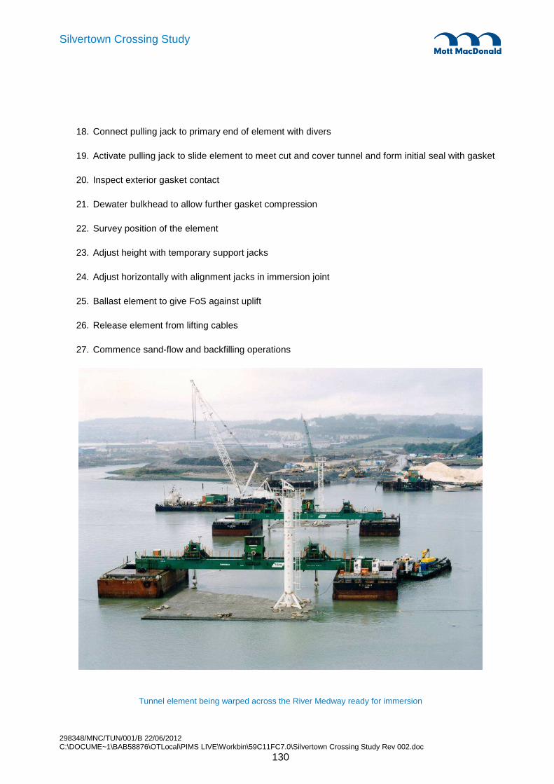
298348/MNC/TUN/001/B 22/06/2012 C:\DOCUME~1\BAB58876\OTLocal\PIMS LIVE\Workbin\59C11FC7.0\Silvertown Crossing Study Rev 002.doc
130
Silvertown Crossing Study
18. Connect pulling jack to primary end of element with divers
19. Activate pulling jack to slide element to meet cut and cover tunnel and form initial seal with gasket
20. Inspect exterior gasket contact
21. Dewater bulkhead to allow further gasket compression
22. Survey position of the element
23. Adjust height with temporary support jacks
24. Adjust horizontally with alignment jacks in immersion joint
25. Ballast element to give FoS against uplift
26. Release element from lifting cables
27. Commence sand-flow and backfilling operations
Tunnel element being warped across the River Medway ready for immersion

298348/MNC/TUN/001/B 22/06/2012 C:\DOCUME~1\BAB58876\OTLocal\PIMS LIVE\Workbin\59C11FC7.0\Silvertown Crossing Study Rev 002.doc
131
Silvertown Crossing Study
Element no. 2, 3 &4
1. Float up tunnel element by controlled de-ballasting
2. Warp tunnel element to entrance of basin
3. As tunnel element exits basin pass beneath catamaran floating pontoon.
4. Attach lowering winch cables to suspension lugs of roof of element
5. Lower temporary support rams on underside of tunnel
6. Position floating anchor platform mid-river upstream and downstream of tunnel
7. Attach long winch cables to anchor platforms
8. Attach fore and aft winch cables from tunnel element to river banks
9. Warp element across river to immersion position
10. Ballast tanks to provide overweight to tunnel element
11. Lower element on winch cables to within 0.5m of cut and cover tunnel
12. Touch element down onto temporary supports
13. Connect pulling jack to primary end of element with divers
14. Activate pulling jack to slide element to meet cut and cover tunnel and form initial seal with gasket
15. Inspect exterior gasket contact
16. Dewater bulkhead to allow further gasket compression
17. Survey position
18. Adjust height with temporary support jacks
19. Adjust horizontally with alignment jacks in immersion joint
20. Ballast element to give FoS against uplift
21. Release element from lifting cables
22. Commence sandflow and backfilling operations

298348/MNC/TUN/001/B 22/06/2012 C:\DOCUME~1\BAB58876\OTLocal\PIMS LIVE\Workbin\59C11FC7.0\Silvertown Crossing Study Rev 002.doc
132
Silvertown Crossing Study
15.4.5 Backfilling
Backfilling requires a number of different operations:
• Pumping sand beneath the tunnel using the sand flow method
• Placing locking fill to the sides of the tunnel to fix lateral position
• Placing general fill to the sides of the tunnel
• Placing filter stone above the sand backfill and across the roof of the tunnel
• Placing rock armour above the tunnel and to 15m either side of the tunnel
Sand flow under the Tunnel Elements - After placing the tunnel elements onto their immersion tiles, a pontoon with a soil/ground pump on board would be used to inject the sand beneath the tunnel element. Such a pump is capable of pumping sand through a pipeline under the tunnel elements, thus grounding them onto a sand layer.
A flattop barge would be used to transport screened sand from an aggregates yard, most likely in the Tilbury area, to the site. Once on site the flattop barge would be moored alongside the pontoon and the sand loaded into the feed hopper for the pump.
Spudleg pontoon for sand flow
Locking Fill and Fill below Filter Layer - The material for the locking fill and fill up to the underside of the filter would be dredged by the Trailing Suction Hopper from and Offshore Crown Licensed Area with the consent of the License Holder. These Licensed Areas are managed by the License holder and are issued by the Crown Estates on behalf of the Crown. The dredger, when dredging on the area, records the position of the ship and dragheads (end of the suction tubes) electronically together with the status of all dredge pumps, bottom doors etc. This information is passed onto the Crown Agents for records. The
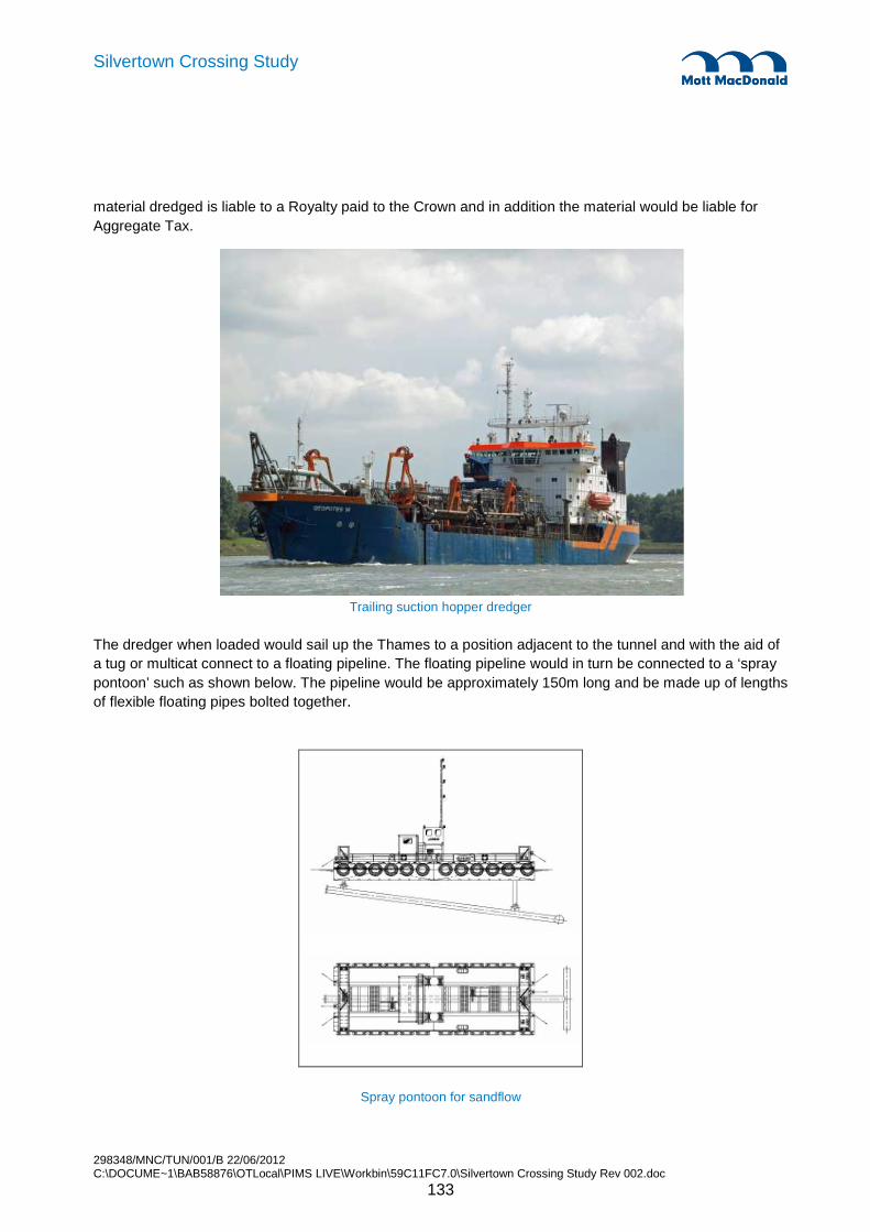
298348/MNC/TUN/001/B 22/06/2012 C:\DOCUME~1\BAB58876\OTLocal\PIMS LIVE\Workbin\59C11FC7.0\Silvertown Crossing Study Rev 002.doc
133
Silvertown Crossing Study
material dredged is liable to a Royalty paid to the Crown and in addition the material would be liable for Aggregate Tax.
Trailing suction hopper dredger
The dredger when loaded would sail up the Thames to a position adjacent to the tunnel and with the aid of a tug or multicat connect to a floating pipeline. The floating pipeline would in turn be connected to a ‘spray pontoon’ such as shown below. The pipeline would be approximately 150m long and be made up of lengths of flexible floating pipes bolted together.
Spray pontoon for sandflow

298348/MNC/TUN/001/B 22/06/2012 C:\DOCUME~1\BAB58876\OTLocal\PIMS LIVE\Workbin\59C11FC7.0\Silvertown Crossing Study Rev 002.doc
134
Silvertown Crossing Study
The Spray Pontoon would be anchored on a system of four anchors and wires during operation. The pontoon would be fitted with positioning equipment such that the operator can see the pontoons position relative to the tunnel elements and side slopes. On a second screen the pipe position would be shown in a vertical display, such that the position is also indicated in cross section relative to the tunnel element and slopes etc. Prior to the TSHD starting its discharge pumps, the pontoon would be positioned in the desired place and the discharge pipe lowered to position. The TSHD would then start pumping water and once the required velocity is reached in the pipeline the sand in the hopper would start to be fluidised with jet pumps and sand discharge commenced. There would be some turbidity in the water, but as the material would contain less than 5% fines, this is not considered to be a problem.
Due to the sailing distance from/to the dredging area the TSHD would be on a 25 hour cycle, that is discharging one load every second high water. When not in position over the trench the spray pontoon and pipeline would be moored along the channel edge, thereby keeping the channel clear. Discharge tome would be about 90 minutes. Consequently disruption to other river users would be minimised. Any trimming required would be carried out by the pontoon prior to placing the filter stone.
Stone Filter Layer and Rock Armour Layer - The rock and stone for the filter and armour layer would be shipped into Tilbury Docks, either by road or rail from UK Quarries or abroad by coaster. The stone would then be back loaded onto small rock transport barges, these barges would be fitted with timber decking to protect the steel deck and also be fitted with low bulwarks to prevent stone accidentally going over the side. The barges would be able to carry something in the order of 1,500 tonnes per load. Each barge would be towed to the tunnel site by tug. The pontoon would be moored on site on a system of 4 anchors, the pontoon would be moored such that when the barge is alongside, the barge would be parallel to the line of the river, in much the same manner as the main dredger and large barges for the excavation, except that in this case the overall with of the unit would be in the order of 24 or 25 metres. The pontoon for this operation would have an excavator mounted, fitted with a position control system. The pontoon would also be fitted with a position control system. The stone would not be dumped, but placed with the excavator bucket. In this manner the there is minimal requirement for any trimming of the top layer and no damage can be done to the tunnel roof. By not using spuds, the pontoon can safely work over all areas of the tunnel, without risk of damage.
Backfill above the Rock Armour Layer - It is not considered necessary to reinstate any backfill above the Armour Protection as this layer is already at or near original river bed levels and siltation will naturally occur and settle in the voids of the rock and soon return the river bed to its previous level. This approach would be discussed and agreed with the EA.
15.4.6 Impact of River Works on Navigation
The marine works activities will need to be coordinated with traffic using the river. Maintaining safe navigation through the construction site for river users is a key concern of the PLA. All movements of vessels and plant will need to be coordinated through the PLA and notice to mariners issued for any change to the navigation channel or markers and to warn of construction works being undertaken in the river.
A mixture of fixed and mobile floating plant is used for the various operations. Other than the immersion activities, which will require a river closure the operations can be carried out with either a temporary reduction in the width of the navigation channel or on the basis that plant will move from the navigation channel for any large vessels passing through the worksite. It is expected that the majority of the vessels

298348/MNC/TUN/001/B 22/06/2012 C:\DOCUME~1\BAB58876\OTLocal\PIMS LIVE\Workbin\59C11FC7.0\Silvertown Crossing Study Rev 002.doc
135
Silvertown Crossing Study
using the river for leisure or commercial purposes will be able to navigate safely with a reduced channel width in conjunction with the appropriate, notices, navigation buoys/markers and coordination.
Cofferdams will be installed on the foreshores most likely by fixed platforms, but these will be out of the main river channel and so not cause an obstruction to navigation.
15.5 Impact to Stakeholders
There will be an impact to a number of important stakeholders for construction of the immersed tunnel. Outside of the London Boroughs of Newham and Greenwich, and TfL there will be specific aspects of the immersed tunnel construction method that will affect in particular:
• Port of London Authority • Environment Agency • Natural England • Thames Estuary Partnership • Docklands Light Railway (DLR) • Emirates Cable Car • Thames Clippers
Each of these Stakeholders will need to be engaged in detailed consultation if the immersed tunnel scheme is to be developed further. A wider group of business enterprises will be affected by any potential river closures. These have not been identified at this time and would need to be consulted at a later stage of scheme development in cooperation with the Port of London Authority.
15.6 Impact on Wharf Operations
The operations in the river or along the river frontage that may be affected are identified in the figure below, along with the likely extent of river closure required for the immersion operation. The impacts from the general marine works construction activities that will have a significant duration – dredging, installing cofferdams and backfilling – along with the impact due to four short closures for immersion of the tunnel elements has been assessed.
To put these activities in perspective the main durations are summarised as: � Installing cofferdams 3 months � Dredging 4 months � Immersing tunnel elements 4 x 48 hour closures of the river at 2 week intervals � Backfilling 3 months � Remove cofferdams 2 months
These operations are largely sequential. However there may be some delay between the operations, particularly the dredging and the activities that follow on afterwards, as the dredging must be carried out during the winter season between 1st September and 31st March. This is described further in Chapter 16 and the overall period over which works in the river may be carried out can be seen on the indicative programme in Appendix C.
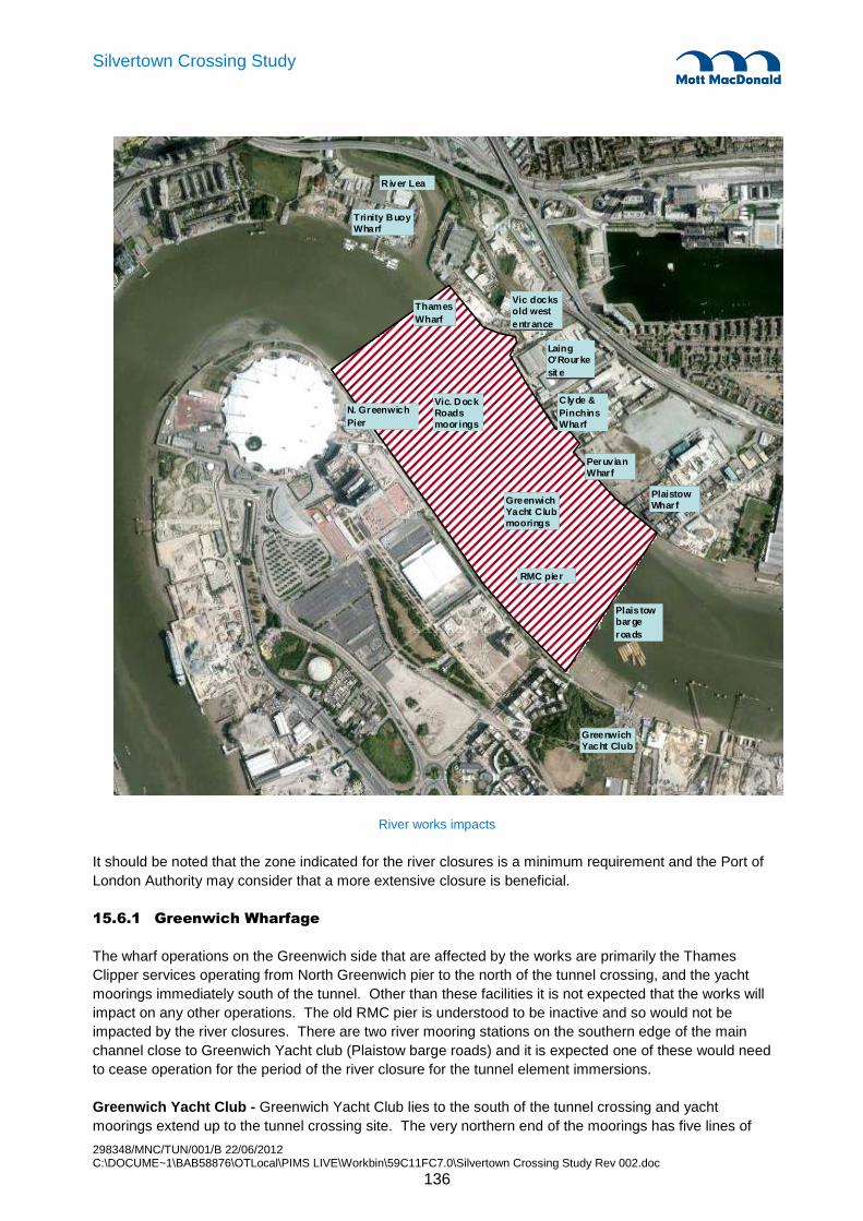
298348/MNC/TUN/001/B 22/06/2012 C:\DOCUME~1\BAB58876\OTLocal\PIMS LIVE\Workbin\59C11FC7.0\Silvertown Crossing Study Rev 002.doc
136
Silvertown Crossing Study
River works impacts
It should be noted that the zone indicated for the river closures is a minimum requirement and the Port of London Authority may consider that a more extensive closure is beneficial.
15.6.1 Greenwich Wharfage
The wharf operations on the Greenwich side that are affected by the works are primarily the Thames Clipper services operating from North Greenwich pier to the north of the tunnel crossing, and the yacht moorings immediately south of the tunnel. Other than these facilities it is not expected that the works will impact on any other operations. The old RMC pier is understood to be inactive and so would not be impacted by the river closures. There are two river mooring stations on the southern edge of the main channel close to Greenwich Yacht club (Plaistow barge roads) and it is expected one of these would need to cease operation for the period of the river closure for the tunnel element immersions.
Greenwich Yacht Club - Greenwich Yacht Club lies to the south of the tunnel crossing and yacht moorings extend up to the tunnel crossing site. The very northern end of the moorings has five lines of
Greenwich Yacht Club
Thames Wharf
N. Greenwich Pier
Vic. Dock Roads moor ings
Clyde & PinchinsWharf
Peruv ian Wharf
Greenwich Yacht Club moorings
RMC pier
Vic docks old west entrance
River Lea
Trinity Buoy Wharf
Laing O’Rourke sit e
Plaistow Whar f
Plais tow barge roads

298348/MNC/TUN/001/B 22/06/2012 C:\DOCUME~1\BAB58876\OTLocal\PIMS LIVE\Workbin\59C11FC7.0\Silvertown Crossing Study Rev 002.doc
137
Silvertown Crossing Study
mooring and approximately 30 moorings would be lost temporarily during the construction works whilst, dredging, immersion and backfilling activities are ongoing. Consultations would need to be held but it is expected that alternative temporary mooring could be provided in the vicinity of the yacht club.
During river closures for the immersion of tunnel elements, access to additional moorings would need to be restricted, along with use of the pier between the yacht club and the tunnel site. The yacht club itself is approximately 600m from the tunnel site and is expected to be far enough away that operation of the club facilities could be maintained.
North Greenwich Pier & Thames Clippers - The Thames clipper service runs from North Greenwich pier to London Bridge, Royal Arsenal Woolwich pier, Greenwich pier and London Bridge pier. Services are frequent and there could be some operational impact whilst the river works are ongoing. The clippers are highly manoeuvrable and Port of London Authority expressed the view that they could maintain operations whilst floating plant are working within the river. The most difficult time for operation will be when the bulk dredging activities are ongoing and movements of barges/coasters collecting dredged materials for disposal would need to be carefully coordinated with the Thames Clipper service and to the satisfaction of the PLA. It is not envisaged that the clipper services would have to be suspended however, except for the immersion operations where the stretch of river to be closed would extend beyond the North Greenwich pier.
15.6.2 Silvertown Wharfs
A number of wharfs operate on the Silvertown side of the river which will be affected to different degrees. Discussions with the Port of London Authority identified key parties and operational issues that have been taken into account in the outline development of the tunnel crossing. One of the areas mentioned by PLA was the mouth of the River Lea ad the immediately adjacent wharves. This has a significant amount of leisure craft usage and would be a difficult and unpopular area to close during the construction works. The general marine activities will not affect river usage or navigation in this area and it is possible to restrict the zone required for the tunnel element immersion to the south of the river mouth.
Thames Wharf - Thames wharf is identified as part of the safeguarded land for the tunnel project and this offers an essential facility for materials import and export by river. The whole of this wharf will therefore need to be utilised as the worksite. The bulk materials required for concrete production, earthworks disposal and the import of materials for backfill to the cut and cover tunnel will be handled at this wharf. Its previous use for waste materials handling shows it is capable of accommodating barges and craneage for these types of activities. The Wharf is in the list of safeguarded wharfs and so will need to be returned to its former use on completion of the works.
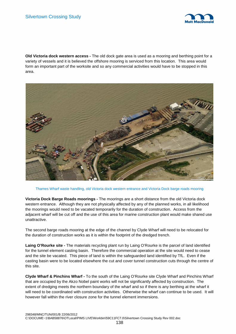
298348/MNC/TUN/001/B 22/06/2012 C:\DOCUME~1\BAB58876\OTLocal\PIMS LIVE\Workbin\59C11FC7.0\Silvertown Crossing Study Rev 002.doc
138
Silvertown Crossing Study
Old Victoria dock western access - The old dock gate area is used as a mooring and berthing point for a variety of vessels and it is believed the offshore mooring is serviced from this location. This area would form an important part of the worksite and so any commercial activities would have to be stopped in this area.
Thames Wharf waste handling, old Victoria dock western entrance and Victoria Dock barge roads mooring
Victoria Dock Barge Roads moorings - The moorings are a short distance from the old Victoria dock western entrance. Although they are not physically affected by any of the planned works, in all likelihood the moorings would need to be vacated temporarily for the duration of construction. Access from the adjacent wharf will be cut off and the use of this area for marine construction plant would make shared use unattractive.
The second barge roads mooring at the edge of the channel by Clyde Wharf will need to be relocated for the duration of construction works as it is within the footprint of the dredged trench.
Laing O’Rourke site - The materials recycling plant run by Laing O’Rourke is the parcel of land identified for the tunnel element casting basin. Therefore the commercial operation at the site would need to cease and the site be vacated. This piece of land is within the safeguarded land identified by TfL. Even if the casting basin were to be located elsewhere the cut and cover tunnel construction cuts through the centre of this site.
Clyde Wharf & Pinchins Wharf - To the south of the Laing O’Rourke site Clyde Wharf and Pinchins Wharf that are occupied by the Akzo Nobel paint works will not be significantly affected by construction. The extent of dredging meets the northern boundary of the wharf and so if there is any berthing at the wharf it will need to be coordinated with construction activities. Otherwise the wharf can continue to be used. It will however fall within the river closure zone for the tunnel element immersions.

298348/MNC/TUN/001/B 22/06/2012 C:\DOCUME~1\BAB58876\OTLocal\PIMS LIVE\Workbin\59C11FC7.0\Silvertown Crossing Study Rev 002.doc
139
Silvertown Crossing Study
Peruvian Wharf and Plaistow Wharf - Further east the Peruvian wharf which is currently a vacant site, although we understand this wharf may be reactivated in the future for aggregate handling as it is a safeguarded wharf, and the Plaistow Wharf further east which is on the Tate & Lyle site will not be affected by the general construction activities but again will fall within the river closure zone.
298348/MNC/TUN/001/B 22/06/2012 C:\DOCUME~1\BAB58876\OTLocal\PIMS LIVE\Workbin\59C11FC7.0\Silvertown Crossing Study Rev 002.doc
140
Silvertown Crossing Study
16.1 Construction Programme
The immersed tube tunnel construction programme is shown in Appendix C .
The programme for the immersed tube tunnel follows from the decision to cast the immersed tube elements in a casting basin on site. Establishing this casting basin at the earliest possible time becomes one of the programme imperatives. The only logical location for the casting basin is on the line of the cut and cover section of tunnel at Silvertown so there is a major civil engineering construction activity to construct the cut and cover section through the former casting basin and this must follow float out of the last element.
Everything else on the programme has to be fitted round these activities or delivered in such a way that it has no avoidable adverse effect on these activities. The works at Greenwich therefore have to be prepared in sufficient time to receive the first of the immersed tube elements as soon as that is ready. This includes the marine works to receive the first element.
The dredging works for the channel must be ready for the immersed tube elements. There is therefore a seasonal impact on the programme as it has been assumed that dredging should be carried out in the winter months to minimise environmental impact on fish spawning and also to allow the works to be carried out when river traffic does not include the seasonal tourist traffic.
As presented the dredging is carried out in one winter and the placing of the elements takes place at the beginning of the following winter. This gives a robust programme as the critical path is through the construction of the elements ready for float out and the dredging is a non-critical activity carried out in advance. There will need to be a secondary sediment sweep dredging operation just ahead of placing the tunnel elements. It is probably possible to carry out the dredging and placing of elements in one winter. This will not shorten the overall programme but it will delay the dredging, reduce its float and risk moving it onto a critical path parallel to constructing the elements.
As presented the commencement of dredging is in November which is month 15 of the programme and preparation of the elements for float out takes place in month 27. Therefore the assumed start date is the beginning of September. There is a little scope for this to move either way but any movement of more than a couple of months either way would lead to a less effective programme. This is something that should be kept in mind as the scheme is further developed.
The Greenwich works might appear to have little relation to the overall programme provided the essential works to receive the first immersed element are completed in time. However, they are important to the overall programme because after the elements are all floated out and the casting basin is emptied, the cut and cover works at Silvertown may prevent access to the immersed tube tunnel from the Silvertown side. It is therefore important to the overall programme that the Greenwich cut and cover and open cut works allow access to the immersed tube section once the immersed tube elements have been installed.
Whilst the need to establish the casting basin and to commence work on the immersed tube elements has been noted above there are activities at Silvertown that are important at an early stage of the programme. It has already been noted that there is a section of cut and cover that must be constructed after the casting basin is emptied. However, there are other Silvertown cut and cover and open ramp works to be
16. Immersed Tube Tunnel – Construction Programme
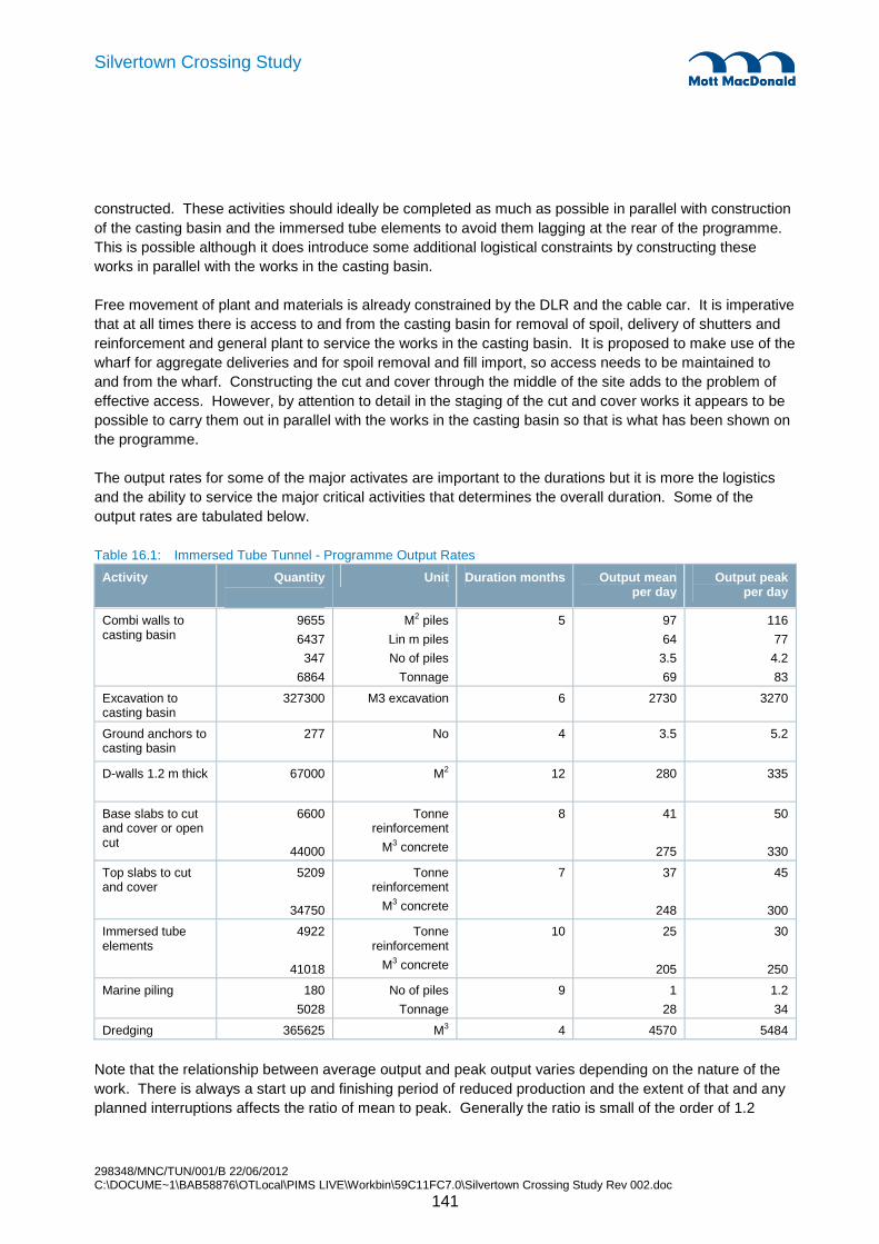
298348/MNC/TUN/001/B 22/06/2012 C:\DOCUME~1\BAB58876\OTLocal\PIMS LIVE\Workbin\59C11FC7.0\Silvertown Crossing Study Rev 002.doc
141
Silvertown Crossing Study
constructed. These activities should ideally be completed as much as possible in parallel with construction of the casting basin and the immersed tube elements to avoid them lagging at the rear of the programme. This is possible although it does introduce some additional logistical constraints by constructing these works in parallel with the works in the casting basin.
Free movement of plant and materials is already constrained by the DLR and the cable car. It is imperative that at all times there is access to and from the casting basin for removal of spoil, delivery of shutters and reinforcement and general plant to service the works in the casting basin. It is proposed to make use of the wharf for aggregate deliveries and for spoil removal and fill import, so access needs to be maintained to and from the wharf. Constructing the cut and cover through the middle of the site adds to the problem of effective access. However, by attention to detail in the staging of the cut and cover works it appears to be possible to carry them out in parallel with the works in the casting basin so that is what has been shown on the programme.
The output rates for some of the major activates are important to the durations but it is more the logistics and the ability to service the major critical activities that determines the overall duration. Some of the output rates are tabulated below.
Table 16.1: Immersed Tube Tunnel - Programme Output Rates
Activity Quantity
Unit Duration months Output mean per day
Output peak per day
Combi walls to casting basin
9655
6437
347
6864
M2 piles
Lin m piles
No of piles
Tonnage
5 97
64
3.5
69
116
77
4.2
83
Excavation to casting basin
327300 M3 excavation 6 2730 3270
Ground anchors to casting basin
277 No 4 3.5 5.2
D-walls 1.2 m thick 67000
M2 12 280 335
Base slabs to cut and cover or open cut
6600
44000
Tonne reinforcement
M3 concrete
8 41
275
50
330
Top slabs to cut and cover
5209
34750
Tonne reinforcement
M3 concrete
7
37
248
45
300
Immersed tube elements
4922
41018
Tonne reinforcement
M3 concrete
10
25
205
30
250
Marine piling 180
5028
No of piles
Tonnage
9 1
28
1.2
34
Dredging 365625 M3 4 4570 5484
Note that the relationship between average output and peak output varies depending on the nature of the work. There is always a start up and finishing period of reduced production and the extent of that and any planned interruptions affects the ratio of mean to peak. Generally the ratio is small of the order of 1.2

298348/MNC/TUN/001/B 22/06/2012 C:\DOCUME~1\BAB58876\OTLocal\PIMS LIVE\Workbin\59C11FC7.0\Silvertown Crossing Study Rev 002.doc
142
Silvertown Crossing Study
The programme shows months as the unit of duration. The month is taken as 20 working days when working out activity durations. This effectively builds in allowances for all the standard bank holidays and construction industry holidays. This is considered to be appropriate at this stage of the project development.
An important item that is not shown on the programme is detailed design. The programme is drawn as a construction programme. Irrespective of the procurement route there will need to be time for detailed design. Whilst some detailed design can be done in parallel with the early construction activities it is important that the overall procurement programme allows sufficient time for detailed design whether this takes place before construction procurement or whether the detailed design is procured as part of a design and construction contract.
The programme is for the scheme with twin road tunnels and a central gallery which is used for emergency access and escape and is also used as a services gallery. This central gallery runs the full length of the immersed tube tunnel including the cut and cover sections. If the central gallery was omitted and the road tunnel cross sections were unchanged there would be a slight time saving for the civil engineering works. However the central gallery is very useful for gaining and early start on the M&E works in a way that is independent of work on the running tunnel civil works and thus the civil engineering time savings will be more than offset by the additional M&E time requirements.

298348/MNC/TUN/001/B 22/06/2012 C:\DOCUME~1\BAB58876\OTLocal\PIMS LIVE\Workbin\59C11FC7.0\Silvertown Crossing Study Rev 002.doc
143
Silvertown Crossing Study
17.1 Cost Estimate
The immersed tube tunnel construction cost estimate has been developed by London Bridge Associates who are working as an integral part of the Mott MacDonald team on this study.
The major cost elements have been prepared by quantifying and then resourcing the major work items with appropriate allowance made for the setting up costs of each activity, the material costs and the time and quantity related resource costs.
For smaller items the costs have used standard quantity based costs and in the detail that follows the basis of pricing is identified.
Certain items have been discussed with industry specialists and where appropriate the pricing has reflected these discussions. These items are also identified in the detail that follows.
The costs are effectively construction costs prepared on the basis of a construction only contract. The costs are current costs at 1st January 2012.
The costs do include supervision and management by the contractor.
The costs do include provision of accommodation for the client on site but do not include client staff costs during the period of onsite works
The limit of works is assumed to be the end of the cut and cover box and vent structure at Greenwich – i.e. the Greenwich portal even though this is some 10 metres below ground. At Silvertown the limit of the works is assumed to be where the open ramp reaches ground level The road works and all M&E works between those limits are included. Provision of external services of electricity, water etc is included but not any offsite construction or other activities that may be necessary for the Silvertown tunnel to perform as part of a wider road network.
The cost of the immersed tube tunnel option is tabulated in summary form below.
17. Immersed Tube Tunnel – Cost Estimate

298348/MNC/TUN/001/B 22/06/2012 C:\DOCUME~1\BAB58876\OTLocal\PIMS LIVE\Workbin\59C11FC7.0\Silvertown Crossing Study Rev 002.doc
144
Silvertown Crossing Study
Table 17.1: Immersed Tube Tunnel –Cost Estimate
SILVERTOWN CROSSING IMMERSED TUBE TUNNEL OPTION.
CONSTRUCTION COST
INSURANCES £16,907,274
CONTRACTORS PRELIMS £37,296,682
DIVERTING DRAIN - P.S. £10,000,000
CASTING BASIN and RIVER WORKS -SILVERTOWN £48,948,861
RIVER WORKS-GREENWICH £7,576,942
DREDGING £22,452,200
CONSTRUCTION OF SUBMERGED UNITS £24,049,553
FLOAT OUT AND POSITION SUBMERGED UNITS £4,618,437
TUNNEL INFILL AND CLADDING TO SUBMERGED UNITS £5,444,965
TUNNEL MECHANICAL AND ELECTRICAL WORKS £43,360,782
SILVERTOWN CUT AND COVER £36,952,819
SILVERTOWN OPEN CUT. £10,692,844
GREENWICH CUT AND COVER £69,188,891
GREENWICH OPEN CUT. Omitted
SUB STATIONS AND VENT BUILDINGS £17,562,500
SUB TOTAL £355,052,748
Contractor's OH and P 10% £35,505,275
IMMERSED TUBE SCHEME
TOTAL £390,558,023
OTHER COSTS
COST FROM QRA ANALYSIS (Chapter 19) 15% £59,000,000
DESIGN COSTS THROUGH TO PROCUREMENT 5% £19,500,000
DETAILED DESIGN COSTS 4% £15,600,000
DESIGN GROWTH 1% £3,905,580
SITE INVESTIGATION £10,000,000
CONSULTANT SUPERVISION COSTS 2% £7,800,000
LAND COSTS (Advised by TfL) £12,000,000
TOTAL SCHEME COST £517,805,580
Three specific opportunities are identified for the immersed tunnel that could result in a major cost reduction for the immersed tunnel. It has not been possible to explore these within the scope of this study but they are documented further in the QRA in Chapter 19.
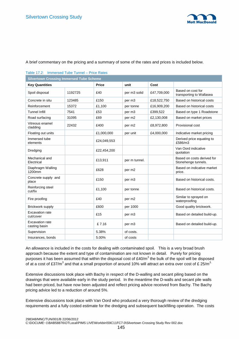
298348/MNC/TUN/001/B 22/06/2012 C:\DOCUME~1\BAB58876\OTLocal\PIMS LIVE\Workbin\59C11FC7.0\Silvertown Crossing Study Rev 002.doc
145
Silvertown Crossing Study
A brief commentary on the pricing and a summary of some of the rates and prices is included below.
Table 17.2: Immersed Tube Tunnel – Price Rates
Silvertown Crossing Immersed Tube Scheme
Key Quantities Price unit Cost
Spoil disposal 1192725 £40 per m3 solid £47,709,000 Based on cost for transporting to Wallasea
Concrete in situ 123485 £150 per m3 £18,522,750 Based on historical costs
Reinforcement 15372 £1,100 per tonne £16,909,200 Based on historical costs
Tunnel Infill 7541 £53 per m3 £399,522 Based on type 1 Roadstone
Road surfacing 31095 £69 per m2 £2,130,008 Based on market prices
Vitreous enamel cladding 22432 £400 per m2 £8,972,800 Provisional cost
Floating out units £1,000,000 per unit £4,000,000 Indicative market pricing
Immersed tube elements £24,049,553 Derived price equating to
£586/m3
Dredging £22,454,200 Van Oord indicative quotation
Mechanical and Electrical £13,911 per m tunnel. Based on costs derived for
Stonehenge tunnels.
Diaphragm Walling 1200mm
£628 per m2 Based on indicative market price.
Concrete supply and place £150 per m3 Based on historical costs.
Reinforcing steel cut/fix £1,100 per tonne Based on historical costs.
Fire proofing £40 per m2 Similar to sprayed on waterproofing
Brickwork supply £600 per 1000 Good quality brickwork.
Excavation rate cut/cover £15 per m3 Based on detailed build-up.
Excavation rate casting basin
£ 7.16 per m3 Based on detailed build-up.
Supervision 5.38% of costs.
Insurances, bonds 5.00% of costs
An allowance is included in the costs for dealing with contaminated spoil. This is a very broad brush approach because the extent and type of contamination are not known in detail. Purely for pricing purposes it has been assumed that within the disposal cost of £40/m3 the bulk of the spoil will be disposed of at a cost of £37/m3 and that a small proportion of around 10% will attract an extra over cost of £ 25/m3.
Extensive discussions took place with Bachy in respect of the D-walling and secant piling based on the drawings that were available early in the study period. In the meantime the D-walls and secant pile walls had been priced, but have now been adjusted and reflect pricing advice received from Bachy. The Bachy pricing advice led to a reduction of around 5%.
Extensive discussions took place with Van Oord who produced a very thorough review of the dredging requirements and a fully costed estimate for the dredging and subsequent backfilling operation. The costs
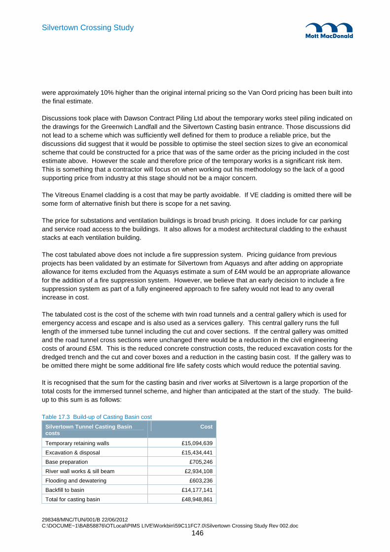
298348/MNC/TUN/001/B 22/06/2012 C:\DOCUME~1\BAB58876\OTLocal\PIMS LIVE\Workbin\59C11FC7.0\Silvertown Crossing Study Rev 002.doc
146
Silvertown Crossing Study
were approximately 10% higher than the original internal pricing so the Van Oord pricing has been built into the final estimate.
Discussions took place with Dawson Contract Piling Ltd about the temporary works steel piling indicated on the drawings for the Greenwich Landfall and the Silvertown Casting basin entrance. Those discussions did not lead to a scheme which was sufficiently well defined for them to produce a reliable price, but the discussions did suggest that it would be possible to optimise the steel section sizes to give an economical scheme that could be constructed for a price that was of the same order as the pricing included in the cost estimate above. However the scale and therefore price of the temporary works is a significant risk item. This is something that a contractor will focus on when working out his methodology so the lack of a good supporting price from industry at this stage should not be a major concern.
The Vitreous Enamel cladding is a cost that may be partly avoidable. If VE cladding is omitted there will be some form of alternative finish but there is scope for a net saving.
The price for substations and ventilation buildings is broad brush pricing. It does include for car parking and service road access to the buildings. It also allows for a modest architectural cladding to the exhaust stacks at each ventilation building.
The cost tabulated above does not include a fire suppression system. Pricing guidance from previous projects has been validated by an estimate for Silvertown from Aquasys and after adding on appropriate allowance for items excluded from the Aquasys estimate a sum of £4M would be an appropriate allowance for the addition of a fire suppression system. However, we believe that an early decision to include a fire suppression system as part of a fully engineered approach to fire safety would not lead to any overall increase in cost.
The tabulated cost is the cost of the scheme with twin road tunnels and a central gallery which is used for emergency access and escape and is also used as a services gallery. This central gallery runs the full length of the immersed tube tunnel including the cut and cover sections. If the central gallery was omitted and the road tunnel cross sections were unchanged there would be a reduction in the civil engineering costs of around £5M. This is the reduced concrete construction costs, the reduced excavation costs for the dredged trench and the cut and cover boxes and a reduction in the casting basin cost. If the gallery was to be omitted there might be some additional fire life safety costs which would reduce the potential saving.
It is recognised that the sum for the casting basin and river works at Silvertown is a large proportion of the total costs for the immersed tunnel scheme, and higher than anticipated at the start of the study. The build-up to this sum is as follows:
Table 17.3 Build-up of Casting Basin cost
Silvertown Tunnel Casting Basin costs
Cost
Temporary retaining walls £15,094,639
Excavation & disposal £15,434,441
Base preparation £705,246
River wall works & sill beam £2,934,108
Flooding and dewatering £603,236
Backfill to basin £14,177,141
Total for casting basin £48,948,861

298348/MNC/TUN/001/B 22/06/2012 C:\DOCUME~1\BAB58876\OTLocal\PIMS LIVE\Workbin\59C11FC7.0\Silvertown Crossing Study Rev 002.doc
147
Silvertown Crossing Study
As can be seen, the casting basin costs are highly dependent on the cost of earthworks excavation and disposal and subsequent backfilling.
298348/MNC/TUN/001/B 22/06/2012 C:\DOCUME~1\BAB58876\OTLocal\PIMS LIVE\Workbin\59C11FC7.0\Silvertown Crossing Study Rev 002.doc
148
Silvertown Crossing Study
18. Ancillary Works
18.1 Tunnel Services Buildings
A primary tunnel services building (single storey ~30m x 25m) has been indicated at the Greenwich side. Access to the ventilation and substation buildings will be required. Hardstanding and parking for 16 vehicles has been provided. The building needs to be serviceable with a 40ft artic and mobile crane with road access to the highway network.
A secondary tunnel services building (single storey ~25m x 10m) has been indicated at the Silvertown side. For this substation we have indicated a hardstanding and parking for 8 vehicles. The building would also be serviceable with a 40ft artic and mobile crane with road access to the highway network.
The substations and the fan housing structures to the vitiated air chimney are located above ground. Some or all of these structures are commonly located below ground in shafts and above the cut and cover tunnel structures. Consideration for integrating and re-locating these structures should be made.
18.2 Power Systems
Security of electrical power supply is paramount. Primary supplies need to be derived from two independent sections of the 11kV network.

298348/MNC/TUN/001/B 22/06/2012 C:\DOCUME~1\BAB58876\OTLocal\PIMS LIVE\Workbin\59C11FC7.0\Silvertown Crossing Study Rev 002.doc
149
Silvertown Crossing Study
19.1 Background
The purpose of the Quantified Risk Assessment (QRA) process was to:
• Identify risks and opportunities for both schemes.
• Quantify the risks and predict the risk exposure of each option in terms of the funding required to cover it. Note: Opportunities (as detailed in Section 18.3) have not been included in the overall calculations or the range of costs for the two options. However the potential opportunity of building the elements off-site has been considered as a separate scenario to show the impact, should this solution be acceptable, as the potential savings would be significant.
Risks were identified and reviewed at two formal risk review workshops involving all key members of the team and TfL.
Further the risk assessment focused on the construction cost of the two schemes and does not include risks for the following stages:
• Scheme Development
• Planning Application
• Procurement
The following costs are also excluded from the cost and risk assessment:
• Client Costs
• Compensation Costs (including Land take)
• Finance Costs
• Differential Inflation
The risk register is included in Appendix D. The risks are restricted to high level risks from a global project perspective. All of the risks identified are considered susceptible to mitigation through management.
19.1.1 Summary of the Process
The initial risk review workshop (held 5th January) was based on the previous risk register for the Bored Tunnel Study (as presented in the Mott McDonalds report “New Thames River Crossing – Silvertown Tunnel Option”, Nov 2009). Each of the existing risks was reviewed against each of the schemes (i.e. whether they were still relevant and if they were applicable also for the Immersed Tunnel Scheme). In addition new generic scheme risks as well as specific risks for each scheme were identified. Following the review the risk register was updated and circulated.
19. Quantified Risk Assessment

298348/MNC/TUN/001/B 22/06/2012 C:\DOCUME~1\BAB58876\OTLocal\PIMS LIVE\Workbin\59C11FC7.0\Silvertown Crossing Study Rev 002.doc
150
Silvertown Crossing Study
The second risk session (held 13th January) used the risk register, the draft cost estimates and the high level programmes for the schemes. The cost estimates were reviewed with regards to overall uncertainty (variability on quantities and rates) that were applied to elements of the cost estimate (as described in Section 18.5). In addition the identified risks were reviewed and where appropriate a quantification was made of the perceived probability of the risk occurring (0-100%) and the associated impact/consequence (expressed as in monetary terms - £).
Following the review the risk register was updated and the cost information imported into a risk model (built in Excel utilising @Risk risk analysis software). This risk model allows the calculation of the overall range of exposure, based on the uncertainties and risks as captured in the risk review (for both of the schemes). From the range of risk exposure a number of statistics can be derived, including the mean/average cost of each scheme and/or confidence levels (e.g. P50 or P80).

298348/MNC/TUN/001/B 22/06/2012 C:\DOCUME~1\BAB58876\OTLocal\PIMS LIVE\Workbin\59C11FC7.0\Silvertown Crossing Study Rev 002.doc
151
Silvertown Crossing Study
19.2 Project Risks
The following is a summary of the key project risks and the associated mitigation measures.
Table 19.1: Project Risks
Silvertown Crossings – Project Risks
Category Risk description Mitigation
Failure to obtain powers and conflicting development requirements.
Engagement with all stakeholder parties. High level or political influencing.
Potential for buildings within safeguarded area on Silvertown side to become listed.
Block listing.
Project delay giving rise to increased development immediately adjacent to tunnel route.
Establish a safeguarded zone. Expedite planning and construction.
Planning & Consent
TfL may have to purchase additional land parcels. Allow additional costs (up to £10-12m)
Compromise on safeguarded area and access requirements. Greater impact for ITT.
More detailed construction planning required.
Additional measures required to avoid objections from the PLA. Greater impact for ITT.
Continued liaison with PLA. Allow additional cost.
PLA imposes a restrictive cap on the number of barge movements per day or per tide etc.
Continued liaison with PLA. Design for barge convoys, maximise barge movements during the night.
PLA may require additional depth below the current bed level of about 1.0m to allow bed erosion and sedimentation to occur. ITT only.
Allow additional cost of extra dredging and backfill
PLA may require additional depth of mud above rock protection to allow anchoring above tunnel. ITT only.
Allow additional cost of extra dredging and backfill.
PLA may not permit closure of the river for immersion. ITT only.
Allow additional cost of developing innovative methods and equipment.
Additional measures required to avoid objections from the LFB. Minimum cross-passage spacing, fire suppression system. Other measures.
Continued liaison with LFB. Allow additional cost.
Additional measures required to deal with close proximity of LCC.
Protection to and monitoring of cable car foundations. Allow additional cost.
Additional measures required to deal with close proximity of DLR.
Allow additional cost.
Stakeholders
Additional measures required to deal with close proximity of other stakeholders. E.g. to remove gas works structures.
Allow additional cost.
Additional measures required to avoid objections from the EA. Impact on marine life, river bed, contamination etc. Greater impact for ITT.
Continued liaison with EA. Allow additional cost.
EA does not allow jet grouting beneath the riverbed to facilitate cross passage construction because of cement and mud pollution. Bored Tunnel only.
Early consultation with EA. Promote Bored tunnel option compared to Immersed tube option.
EA may object to cofferdams due to flow disturbance. ITT only.
Allow additional cost for increase in dredging and protection works to river walls.
EA may object to cofferdams due to loss of mudflat habitat. ITT only.
Allow additional cost for mitigation measures.
EA may object to piling through remediated land with ground membrane.
Allow additional cost and programme for alternative solution.
Environment
Additional measures required to avoid objections from Nature England, Marine Management, Green organisations etc. Greater impact for ITT.
Continued liaison. Allow additional cost.

298348/MNC/TUN/001/B 22/06/2012 C:\DOCUME~1\BAB58876\OTLocal\PIMS LIVE\Workbin\59C11FC7.0\Silvertown Crossing Study Rev 002.doc
152
Silvertown Crossing Study
Silvertown Crossings – Project Risks
Objections due to pollution, noise, dust, light, traffic management, 24 hour working etc.
Additional mitigation measures. Allow additional cost.
Increase in amount of contaminated material. Costs have been based on 50% contaminated material at Greenwich and none at Silvertown. Allow additional costs.
Thames River to be classified as Marine Conservation area resulting in more stringent controls and regulations. Greater impact for ITT.
Allow additional costs to mitigate.
Flooding of tunnel during construction and operation. Consider flood prevention further during detail design.
Thames flood defences are breached and tunnel is flooded.
Locate critical equipment above flood level e.g. tunnel standby generator
Design, scope creep due to conditions imposed by stakeholders, third parties, design development, scheme development, site Investigation works, procurement etc.
Allow additional costs. E.g. to provide fire suppression, fancy portal structures, alignment change, structure changes etc.
Provide independent power supply such as generators. Allow additional cost to provide generators. (Not allowed for in cost estimate).
ADR category E is changed which may increase fire life safety requirements and pumping requirements.
Allow additional cost to provide additional ventilation, tunnel size, additional pumping etc. (Not allowed for in cost estimate).
Architectural finish to towers is more elaborate than allowed for.
Allow additional cost.
Design for 100MW fire increased to 200MW fire. Allow additional cost.
Change to legal requirements and standards or key design parameters.
Allow additional cost.
Green-wave cannot be achieved at exiting portals. Allow additional cost to provide larger tunnel and transverse ventilation system. Revise highway details at portal.
More stringent requirements for discharge of drainage water required.
Allow additional costs.
Design and Approvals
More elaborate launch chamber required to launch TBM on a curved alignment.
Allow additional cost. (Not allowed in cost estimate).
Blow out or failure due to low ground cover to bored tunnel crown.
Detailed Site Investigation and if shown necessary ground treatment. Provide protection at river bed.
TBM failure during tunnel excavation. Good TBM spec, TBM intervention at mid-point.
Hard layers in ground slowing TBM advance and excessive wear on cutters.
More SI, Good TBM spec, TBM intervention at mid-point.
Encounter obstructions during TBM excavation. Allow additional programme and costs.
Encounter obstructions during piling and constructing diaphragm walls.
Allow additional programme and costs.
Utility diversions required are greater than anticipated. Allow additional programme and costs.
Unexploded ordnance encountered. Carry out specialist survey.
Additional river closures required for ITT construction. 5 weekend closures have been assumed. Allow additional programme and costs.
Depth of cohesive soil may be insufficient beneath casting basin to provide adequate ground water cut-off or resistance.
Additional cost for pressure relief and sump pumping (small cost only)
Construction
Hard material may be encountered during dredging / piling
Allow additional cost.
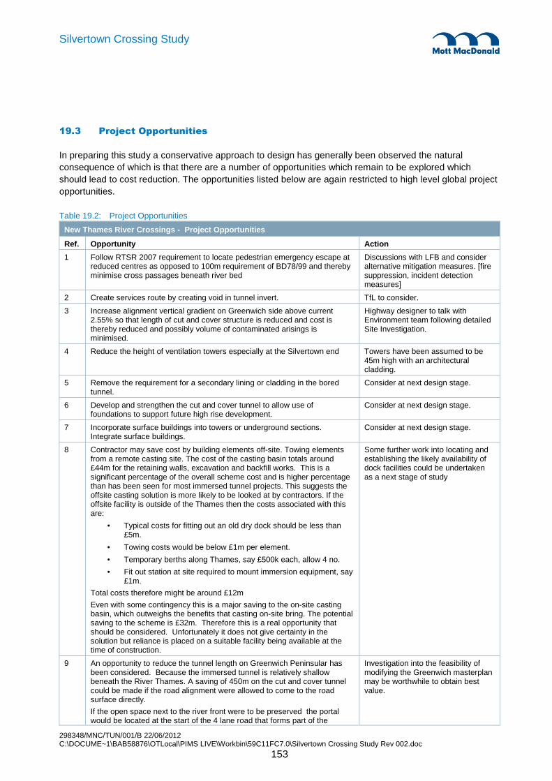
298348/MNC/TUN/001/B 22/06/2012 C:\DOCUME~1\BAB58876\OTLocal\PIMS LIVE\Workbin\59C11FC7.0\Silvertown Crossing Study Rev 002.doc
153
Silvertown Crossing Study
19.3 Project Opportunities
In preparing this study a conservative approach to design has generally been observed the natural consequence of which is that there are a number of opportunities which remain to be explored which should lead to cost reduction. The opportunities listed below are again restricted to high level global project opportunities.
Table 19.2: Project Opportunities
New Thames River Crossings - Project Opportunities
Ref. Opportunity Action
1 Follow RTSR 2007 requirement to locate pedestrian emergency escape at reduced centres as opposed to 100m requirement of BD78/99 and thereby minimise cross passages beneath river bed
Discussions with LFB and consider alternative mitigation measures. [fire suppression, incident detection measures]
2 Create services route by creating void in tunnel invert. TfL to consider.
3 Increase alignment vertical gradient on Greenwich side above current 2.55% so that length of cut and cover structure is reduced and cost is thereby reduced and possibly volume of contaminated arisings is minimised.
Highway designer to talk with Environment team following detailed Site Investigation.
4 Reduce the height of ventilation towers especially at the Silvertown end Towers have been assumed to be 45m high with an architectural cladding.
5 Remove the requirement for a secondary lining or cladding in the bored tunnel.
Consider at next design stage.
6 Develop and strengthen the cut and cover tunnel to allow use of foundations to support future high rise development.
Consider at next design stage.
7 Incorporate surface buildings into towers or underground sections. Integrate surface buildings.
Consider at next design stage.
8 Contractor may save cost by building elements off-site. Towing elements from a remote casting site. The cost of the casting basin totals around £44m for the retaining walls, excavation and backfill works. This is a significant percentage of the overall scheme cost and is higher percentage than has been seen for most immersed tunnel projects. This suggests the offsite casting solution is more likely to be looked at by contractors. If the offsite facility is outside of the Thames then the costs associated with this are:
• Typical costs for fitting out an old dry dock should be less than £5m.
• Towing costs would be below £1m per element.
• Temporary berths along Thames, say £500k each, allow 4 no.
• Fit out station at site required to mount immersion equipment, say £1m.
Total costs therefore might be around £12m
Even with some contingency this is a major saving to the on-site casting basin, which outweighs the benefits that casting on-site bring. The potential saving to the scheme is £32m. Therefore this is a real opportunity that should be considered. Unfortunately it does not give certainty in the solution but reliance is placed on a suitable facility being available at the time of construction.
Some further work into locating and establishing the likely availability of dock facilities could be undertaken as a next stage of study
9 An opportunity to reduce the tunnel length on Greenwich Peninsular has been considered. Because the immersed tunnel is relatively shallow beneath the River Thames. A saving of 450m on the cut and cover tunnel could be made if the road alignment were allowed to come to the road surface directly.
If the open space next to the river front were to be preserved the portal would be located at the start of the 4 lane road that forms part of the
Investigation into the feasibility of modifying the Greenwich masterplan may be worthwhile to obtain best value.

298348/MNC/TUN/001/B 22/06/2012 C:\DOCUME~1\BAB58876\OTLocal\PIMS LIVE\Workbin\59C11FC7.0\Silvertown Crossing Study Rev 002.doc
154
Silvertown Crossing Study
New Thames River Crossings - Project Opportunities planned development. This would require a further 100m of cut and cover but would still constitute a saving of 350m of cut and cover tunnel.
Either of these options would need some minor modification to the Master plan to allow space for side roads to either side of the tunnel crossing. This may or may not be possible depending on how fixed the Masterplan is. Figure 19.1 illustrates the case where the portal is at the closest possible point to the river.
The cost of the cut and cover tunnel construction at Greenwich is approximately £125,000 per m of tunnel. n assessing the potential costs savings for this a pro rata adjustment of total cost for the cut and cover section is not entirely appropriate but it would be reasonable to take 90% of this figure.
For the maximum reduction of 450m the saving would therefore be £50.6m and for the option for preserving the open space the saving would be £39.5m. Note this does not take into account the saving in M&E systems and tunnel finishes.
10 Omission of central gallery. The central gallery provides a route for emergency escape and a route for emergency intervention into the tunnel. It also provides some maintenance access for a limited number of activities. It offers enhanced functionality compared to the bored tunnel in these respects and also some additional flexibility for future upgrading of the tunnel, if it were ever required.
In short immersed tunnels a central gallery is often not provided and the tunnel operation plan is developed to enable safe normal operation as well as safe procedures for dealing with incidents.
The choice of whether the central gallery is provided will depend on a detailed assessment of operating procedures and risks, and the cost-benefit analysis that accompanies this. The outcome could find either option is viable in which case there may be opportunity to save capital cost.
The width of the gallery plus a portion of the dividing wall is approximately 2.0m. The omission of the gallery would allow a £5m cost reduction on the excavation, concreting works, backfilling and finishing works.
Consider at next design stage.
11 Consider use for the casting basin when the tunnel is completed (tied into future development as a basement, u/g parking, marina/public amenity area etc.)
Consider at next design stage.
12 Depth of basin could be reduced further to reduce wall cost. Marine contractor would have to work with tides to exit the basin.
Consider at next design stage.
13 Provide fire suppression system. The cost estimate does not include a fire suppression system. Pricing guidance from previous projects estimate a sum of £4M would be an appropriate allowance for the addition of a fire suppression system. However, we believe that an early decision to include a fire suppression system as part of a fully engineered approach to fire safety could be off-set by savings elsewhere from a fully engineered approach to fire safety.
Consider at next design stage.
14 There is an opportunity for the TBM intervention not to be used. Further Site investigation required.

298348/MNC/TUN/001/B 22/06/2012 C:\DOCUME~1\BAB58876\OTLocal\PIMS LIVE\Workbin\59C11FC7.0\Silvertown Crossing Study Rev 002.doc
155
Silvertown Crossing Study
Figure 19.1: Greenwich end Immersed Tube Tunnel Opportunity
19.4 Quantified Risk Assessment Results
The results of the risk assessment (See modelling notes in Section 18.5) indicate the following range of outturn cost for the two options. The PX% values show the percentile values for the risk exposure, based on the modelled risks. As an example using table 19.3, the P80% indicate that there is an 80% chance that the outturn cost of this option is £394.2m or less for the Bored Tunnel Option.
The two outturn costs are distinctly different which is further illustrated in figure 19.2.

298348/MNC/TUN/001/B 22/06/2012 C:\DOCUME~1\BAB58876\OTLocal\PIMS LIVE\Workbin\59C11FC7.0\Silvertown Crossing Study Rev 002.doc
156
Silvertown Crossing Study
Table 19.3: Results of the QRA
Bored Tunnel Option
Immersed Tunnel Option
Base Cost (excluding Risk Allowances)
£337.0m £390.6m
Average / Mean Cost £386.0m £446.1m
P05% £370.3m £430.6m
P20% £377.3m £439.4m
P50% £386.0m £449.0m
P80% £394.2m £459.8m
P95% £402.0m £469.0m
Figure 19.2: Range of Outturn Cost Comparison of the two Schemes
0.0
0.0
0.0
0.0
0.0
0.0
0.0
0.0
0.0
0.0
340
360
380
400
420
440
460
480
500
Probability
Values in Millions (£)
Comparing the two Schemes - Range of Costs
Immersed Tunnel
Bored Tunnel
The key uncertainties and risks are shown in figures 19.3 (Bored Tunnel Option) and 19.4 (Immersed Tunnel Option). These have been ranked on their influence on the overall cost uncertainty (correlation with the overall cost uncertainty) and are presented in Tornado Charts. Further details on the risks and uncertainties can be found in section 19.5.

298348/MNC/TUN/001/B 22/06/2012 C:\DOCUME~1\BAB58876\OTLocal\PIMS LIVE\Workbin\59C11FC7.0\Silvertown Crossing Study Rev 002.doc
157
Silvertown Crossing Study
Figure 19.3: Key Uncertainties and Risks – Tornado Chart
0 0.1 0.2 0.3 0.4 0.5 0.6
E11 - Estimating Uncertainty / Launch Chamber Portal Construction
E17 - Estimating Uncertainty / Silvertown Cut and Cover
22 - Risk / Overall visual impacts
E21 - Estimating Uncertainty / Sub Stations and Vent Buildings
E09 - Estimating Uncertainty / TBM Supply, Erect and Dismantle
E19 - Estimating Uncertainty / Greenwich Cut and Cover
E18 - Estimating Uncertainty / Silvertown Open Cut
E15 - Estimating Uncertainty / Tunnel Fill and Cladding
E12 - Estimating Uncertainty / Cross Passages
37 - Risk / Unacceptable impact of Chimneys/ventilation shafts
E10 - Estimating Uncertainty / TBM Driving Costs
E23 - Estimating Uncertainty / Overhead and Profit
E03 - Estimating Uncertainty / Diverting Drain
E16 - Estimating Uncertainty / Tunnel Mechanical and Electrical Works
E25 - Estimating Uncertainty / Contractor Risk Premium
Correlation
Figure 19.4: Key Uncertainties and Risks – Tornado Chart – Immersed Tunnel Option Figure
0 0.05 0.1 0.15 0.2 0.25 0.3 0.35 0.4 0.45
19 - Risk / Contaminated Ground
6 - Risk / Overlapping construction period with other projects
14 - Risk / Objections from EA
E18 - Estimating Uncertainty / Silvertown Open Cut
E05 - Estimating Uncertainty / River Works - Greenwich
E08 - Estimating Uncertainty / Float out and Position Submerged Units
E07 - Estimating Uncertainty / Construction of Submerged Units
3 - Risk / Changes to the construction methodology / sequence
E15 - Estimating Uncertainty / Tunnel Fill and Cladding
37 - Risk / Unacceptable impact of Chimneys/ventilation shafts
E17 - Estimating Uncertainty / Silvertown Cut and Cover
E06 - Estimating Uncertainty / Dredging
E19 - Estimating Uncertainty / Greenwich Cut and Cover
E23 - Estimating Uncertainty / Overhead and Profit
E03 - Estimating Uncertainty / Diverting Drain
E16 - Estimating Uncertainty / Tunnel Mechanical and Electrical Works
E04 - Estimating Uncertainty / Casting Basin and River Works - Silvertown
Correlation

298348/MNC/TUN/001/B 22/06/2012 C:\DOCUME~1\BAB58876\OTLocal\PIMS LIVE\Workbin\59C11FC7.0\Silvertown Crossing Study Rev 002.doc
158
Silvertown Crossing Study
19.4.1 Opportunities identified for immersed tunnel
Three specific opportunities are identified for the immersed tunnel that could result in a major cost reduction. These are items 8, 9 & 10 from table 19.2, as the possible savings identified are as follows: � Casting tunnel elements offsite, which offers a saving of £32m � Reduction in length of Greenwich cut and cover tunnel which offers a saving of £40-50m � Omission of central gallery which offers a saving of £5m � Associated prelims costs for the above three items (assuming 25%) is £20m � Total possible saving £97m-£107m
Taking these opportunities into consideration could reduce the total base cost to £283m-293m .
There would also be programme savings associated with e casting of tunnel elements off-site which have not as yet been evaluated. These opportunities may therefore warrant further study to asses their viability fully.
The distribution of cost according to the QRA risk analysis will most likely be similar to the base case but has not been re-calculated at this time for all the opportunities identified.
19.5 Quantified Risk Assessment – Modelling Notes
This Section details how the modelling was carried out for each element.
Table 19.4: Modelling Notes for the QRA
REF ITEM Bored Tunnel Option (Base Cost)
Immersed Tunnel Option
(Base Cost)
Bored Tunnel Option
Estimating Uncertainties
Immersed Tunnel Option
Estimating Uncertainties
E01 Insurances £14.6M £16.9M Assumed to vary with the overall base cost (Sub Total) no risk included to the relative cost of insurances.
Assumed to vary with the overall base cost (Sub Total) no risk included to the relative cost of insurances.
E02 Contractors Prelims £40.5M £37.3M Robust allowances built from first principles. Will vary in line with overall costs.
Robust allowances built from first principles. Will vary in line with overall costs.
E03 Diverting Drain £10.0M £10.0M Scope for the diversion is not yet clearly defined and the item carries considerable risk. Allow a range of £5m to £15m for the overall cost of the works.
Scope for the diversion is not yet clearly defined and the item carries considerable risk. Allow a range of £5m to £15m for the overall cost of the works.

298348/MNC/TUN/001/B 22/06/2012 C:\DOCUME~1\BAB58876\OTLocal\PIMS LIVE\Workbin\59C11FC7.0\Silvertown Crossing Study Rev 002.doc
159
Silvertown Crossing Study
REF ITEM Bored Tunnel Option (Base Cost)
Immersed Tunnel Option
(Base Cost)
Bored Tunnel Option
Estimating Uncertainties
Immersed Tunnel Option
Estimating Uncertainties
E04 Casting Basin and River Works - Silvertown
n/a £48.9M n/a Estimate assumes that all 4 units will be built more of less in parallel. Uncertainties in the estimate for ground conditions, obstructions, and design (temporary) covered by -10% to +15% allowance.
E05 River Works - Greenwich n/a £7.6M n/a High level of uncertainty in the final requirements (especially the removal, temporary solution and reinstatement of ship protection system) - allow a -5% to +30% overall uncertainty on the cost.
E06 Dredging n/a £22.5M n/a Based on current market prices, allow +/-10%.
E07 Construction of Submerged Units
n/a £24.0M n/a Allow overall uncertainty of -5% to 10%.
E08 Float out and Position Submerged Units
n/a £4.6M n/a High level allowance subject to -20% to +50% uncertainty.
E09 TBM Supply, Erect and Dismantle
£30.4M n/a Estimate could be on the high side and overall could reduce with up to 10%, allow a
-10% to ±0% range, with a most likely of 0% increased cost.
n/a
E10 TBM Driving Costs £49.3M n/a Cost uncertainty applied as follows:
(a) Segments - £20m, cost uncertainty could increase with up to 10%.
(b) Spoil disposal - £10m, could increase with up to 25%.
(c) Cost of Interventions - £1m, could range from -10% to +40%.
(d) residual cost, allow +/-10%
n/a
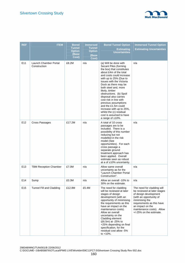
298348/MNC/TUN/001/B 22/06/2012 C:\DOCUME~1\BAB58876\OTLocal\PIMS LIVE\Workbin\59C11FC7.0\Silvertown Crossing Study Rev 002.doc
160
Silvertown Crossing Study
REF ITEM Bored Tunnel Option (Base Cost)
Immersed Tunnel Option
(Base Cost)
Bored Tunnel Option
Estimating Uncertainties
Immersed Tunnel Option
Estimating Uncertainties
E11 Launch Chamber Portal Construction
£8.2M n/a (a) Will be done with Secant Piles (forming the box) that constitutes about £4m of the total and costs could increase with up to 25% (Due to issues with the Victoria Dock as there may be both steel and, more likely, timber obstructions. (b) Spoil disposal also carries cost risk in line with previous assumptions and the £1.5m could increase with up to 25%, whilst the (c) residual cost is assumed to have a range of ±10%.
n/a
E12 Cross Passages £17.2M n/a A total of 10 cross passages are to be included. There is a possibility of this number reducing but not modelled in the risk model (See opportunities). For each cross passage a separate ground treatment approach has been applied. Overall estimate seen as robust at a of ±10% uncertainty.
n/a
E13 TBM Reception Chamber £7.0M n/a Allow same overall uncertainty as for the "Launch Chamber Portal Construction".
n/a
E14 Sump £0.3M n/a Allow an overall -10% to 30% on the estimate.
n/a
E15 Tunnel Fill and Cladding £12.8M £5.4M The need for cladding will be reviewed at later stages of design development (with an opportunity of minimising the requirements as this have an impact on the maintenance costs). Allow an overall uncertainty on the Cladding element (£6.5m) at -25% to +25% depending on final specification, for the residual cost allow -5% to +10%.
The need for cladding will be reviewed at later stages of design development (with an opportunity of minimising the requirements as this have an impact on the maintenance costs). Allow +/-25% on the estimate.

298348/MNC/TUN/001/B 22/06/2012 C:\DOCUME~1\BAB58876\OTLocal\PIMS LIVE\Workbin\59C11FC7.0\Silvertown Crossing Study Rev 002.doc
161
Silvertown Crossing Study
REF ITEM Bored Tunnel Option (Base Cost)
Immersed Tunnel Option
(Base Cost)
Bored Tunnel Option
Estimating Uncertainties
Immersed Tunnel Option
Estimating Uncertainties
E16 Tunnel Mechanical and Electrical Works
£42.2M £43.4M Allow -10% to +15% for the costs. Uncertainty lies in costs of SCADA and LED.
Allow -10% to +15% for the costs. Uncertainty lies in costs of SCADA and LED.
E17 Silvertown Cut and Cover £18.4M £37.0M Relatively straightforward, allow +/-5% on the overall cost.
Relatively straightforward, allow +/-5% on the overall cost.
E18 Silvertown Open Cut £12.7M £10.7M Depending on methodology estimate could be on the high side, allow -20% to +5% on the overall cost.
Depending on methodology estimate could be on the high side, allow -20% to +5% on the overall cost.
E19 Greenwich Cut and Cover £25.0M £69.2M Relatively straightforward, allow +/-5% on the overall cost.
Relatively straightforward, allow +/-5% on the overall cost.
E20 Greenwich Open Cut £0.0M £0.0M Omitted. -
E21 Sub Stations and Vent Buildings
£17.9M £17.6M Additional considerations to be given for maintenance/ operational facilities. Allow costs to increase with up to 10%.
Additional considerations to be given for maintenance/ operational facilities. Allow costs to increase with up to 10%.
E22 Sub Total 1 £306.3M £355.1M - -
E23 Overhead and Profit £30.6M £35.5M Base assumption at 10% allow range of 9..12% in the risk model.
Base assumption at 10% allow range of 9..12% in the risk model.
E24 Sub Total 2 £337.0M £390.6M -
E25 Contractor Risk Premium £33.7M £39.1M Base Assumption at 10% allow range of 8..13% in the risk model.
Base Assumption at 10% allow range of 8..13% in the risk model.
E26 Total Base Cost £370.6M £429.6M - -
Modelled Risks - Full register can be found in Appe ndix D - -
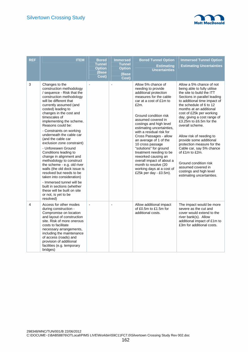
298348/MNC/TUN/001/B 22/06/2012 C:\DOCUME~1\BAB58876\OTLocal\PIMS LIVE\Workbin\59C11FC7.0\Silvertown Crossing Study Rev 002.doc
162
Silvertown Crossing Study
REF ITEM Bored Tunnel Option (Base Cost)
Immersed Tunnel Option
(Base Cost)
Bored Tunnel Option
Estimating Uncertainties
Immersed Tunnel Option
Estimating Uncertainties
3 Changes to the construction methodology / sequence - Risk that the construction methodology will be different that currently assumed (and costed) leading to changes in the cost and timescales of implementing the scheme. Reasons could be:
- Constraints on working underneath the cable car (and the cable car exclusion zone constraint)
- Unforeseen Ground Conditions leading to change in alignment and methodology to construct the scheme - e.g. old river walls (the old dock issue is resolved but needs to be taken into consideration)
- Immersed tunnel will be built in sections (whether these will be built on site or not, is yet to be resolved)
- - Allow 5% chance of needing to provide additional protection measures for the cable car at a cost of £1m to £2m.
Ground condition risk assumed covered in costings and high level estimating uncertainties, with a residual risk for Cross Passages - allow an average of 1 of the 10 cross passage "solutions" for ground treatment needing to be reworked causing an overall impact of about a month to resolve (20 working days at a cost of £25k per day - £0.5m).
Allow a 5% chance of not being able to fully utilise the site to build the ITT Sections in parallel leading to additional time impact of the schedule of 6 to 12 months at an additional cost of £25k per working day, giving a cost range of £3.25m to £6.5m for the overall scheme.
Allow risk of needing to provide some additional protection measure for the Cable car, say 5% chance of £1m to £2m.
Ground condition risk assumed covered in costings and high level estimating uncertainties.
4 Access for other modes during construction - Compromise on location and layout of construction site. Risk of more onerous costs to facilitate necessary arrangements, including the maintenance of access (roads) and provision of additional facilities (e.g. temporary bridges)
- - Allow additional impact of £0.5m to £1.5m for additional costs.
The impact would be more severe as the cut and cover would extend to the river bank(s). Allow additional impact of £1m to £3m for additional costs.

298348/MNC/TUN/001/B 22/06/2012 C:\DOCUME~1\BAB58876\OTLocal\PIMS LIVE\Workbin\59C11FC7.0\Silvertown Crossing Study Rev 002.doc
163
Silvertown Crossing Study
REF ITEM Bored Tunnel Option (Base Cost)
Immersed Tunnel Option
(Base Cost)
Bored Tunnel Option
Estimating Uncertainties
Immersed Tunnel Option
Estimating Uncertainties
5 Mitigation measures required to avoid objections from the PLA - PLA may object to the scheme on the grounds of Environmental Impacts and/or the impact on River Navigation (during construction as well as operations), maintenance dredging, bringing in materials/spoil disposal and general river access. Potential mitigations may be required (Also see risk on River Closures required and the risk of maintenance impact on the tunnel crown).
Further PLA have raised a concern regarding the risk strategy for the cable car that assumes that ships can drop anchor if necessary which may be prevented with an ITT.
- - No additional risk modelled.
Assumed programme takes consideration of initial feedback of doing the dredging and the floating out of the ITT Sections during two consecutive winters.
Allow a 50/50 chance of needing to change the assumed dredging method not to put the sediment back into the river flow (e.g. by using a suction method). Allow the incremental cost to be in the range of £0.5m to £2m.
6 Overlapping construction period with other projects - Delay or advance of other projects impacting on tunnel - overlapping construction periods leading to Cumulative noise, vibration etc. Could have an impact due to the Interface with Master Plan North and South. Risk regarded as relatively small and would impact both options.
- - No major impacts assumed.
Additional interface risk with the Thames Tideway project (if the projects occur at the same time). Would possibly lead to problems associated with the movement of barges. Allow a 20% chance of an increased cost of £1m to £3m.
8 South Station access (impact on) cable car - Constraint to the design and potential changes.
- - Small risk, considered in design. Allow a 5% chance of additional impact of £0.5m to £1m.
Detail to be checked for suitability. Will be resolved during design development. But at this stage a risk. Allow 5% chance of £0.5m to £1m.
9 Potential Thames Wharf DLR station in close proximity to north portal - Need to revise designs to take into account Thames Wharf DLR Station. As there are currently no detailed plans for the station this could lead to changes to the current design.
- - Allow a 5% chance of additional costs ranging from £0.5m to £1m.
Allow a 5% chance of additional costs ranging from £0.5m to £1m.
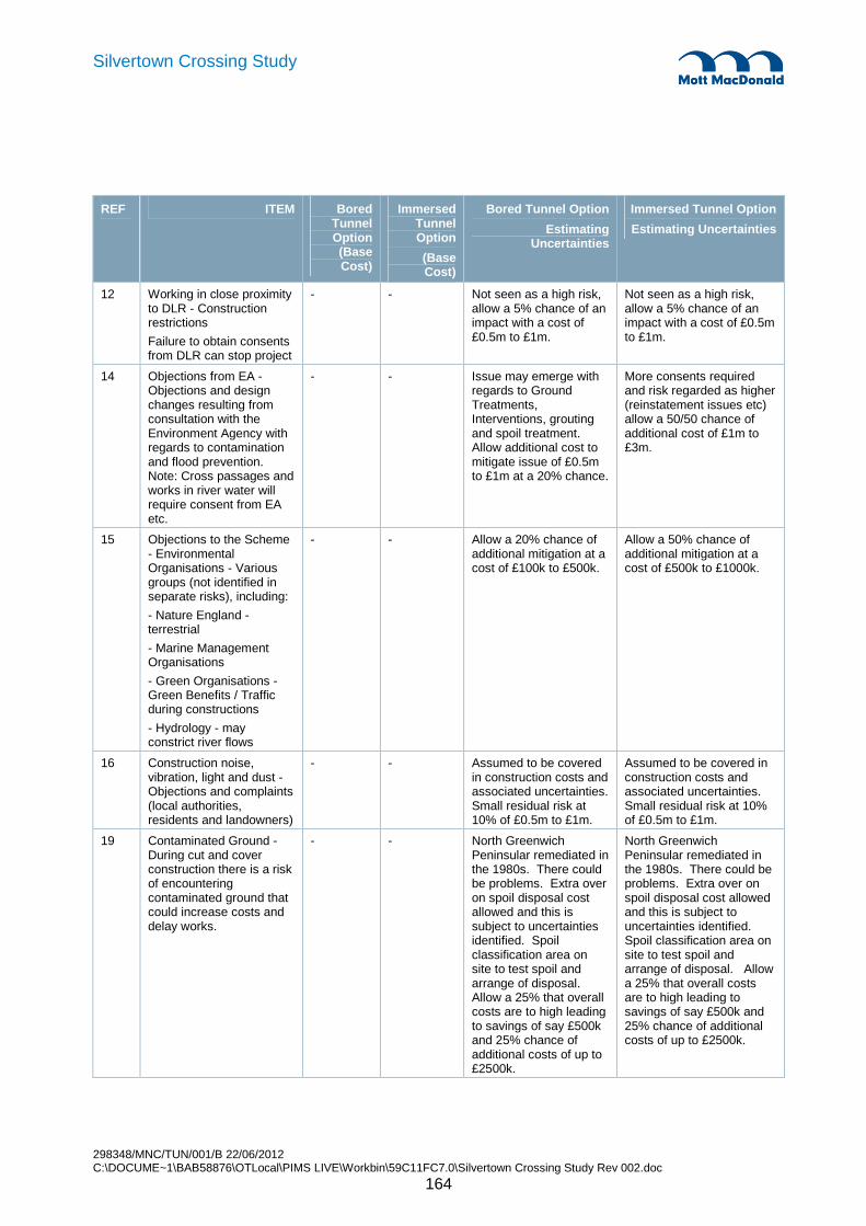
298348/MNC/TUN/001/B 22/06/2012 C:\DOCUME~1\BAB58876\OTLocal\PIMS LIVE\Workbin\59C11FC7.0\Silvertown Crossing Study Rev 002.doc
164
Silvertown Crossing Study
REF ITEM Bored Tunnel Option (Base Cost)
Immersed Tunnel Option
(Base Cost)
Bored Tunnel Option
Estimating Uncertainties
Immersed Tunnel Option
Estimating Uncertainties
12 Working in close proximity to DLR - Construction restrictions
Failure to obtain consents from DLR can stop project
- - Not seen as a high risk, allow a 5% chance of an impact with a cost of £0.5m to £1m.
Not seen as a high risk, allow a 5% chance of an impact with a cost of £0.5m to £1m.
14 Objections from EA - Objections and design changes resulting from consultation with the Environment Agency with regards to contamination and flood prevention. Note: Cross passages and works in river water will require consent from EA etc.
- - Issue may emerge with regards to Ground Treatments, Interventions, grouting and spoil treatment. Allow additional cost to mitigate issue of £0.5m to £1m at a 20% chance.
More consents required and risk regarded as higher (reinstatement issues etc) allow a 50/50 chance of additional cost of £1m to £3m.
15 Objections to the Scheme - Environmental Organisations - Various groups (not identified in separate risks), including:
- Nature England - terrestrial
- Marine Management Organisations
- Green Organisations - Green Benefits / Traffic during constructions
- Hydrology - may constrict river flows
- - Allow a 20% chance of additional mitigation at a cost of £100k to £500k.
Allow a 50% chance of additional mitigation at a cost of £500k to £1000k.
16 Construction noise, vibration, light and dust - Objections and complaints (local authorities, residents and landowners)
- - Assumed to be covered in construction costs and associated uncertainties. Small residual risk at 10% of £0.5m to £1m.
Assumed to be covered in construction costs and associated uncertainties. Small residual risk at 10% of £0.5m to £1m.
19 Contaminated Ground - During cut and cover construction there is a risk of encountering contaminated ground that could increase costs and delay works.
- - North Greenwich Peninsular remediated in the 1980s. There could be problems. Extra over on spoil disposal cost allowed and this is subject to uncertainties identified. Spoil classification area on site to test spoil and arrange of disposal. Allow a 25% that overall costs are to high leading to savings of say £500k and 25% chance of additional costs of up to £2500k.
North Greenwich Peninsular remediated in the 1980s. There could be problems. Extra over on spoil disposal cost allowed and this is subject to uncertainties identified. Spoil classification area on site to test spoil and arrange of disposal. Allow a 25% that overall costs are to high leading to savings of say £500k and 25% chance of additional costs of up to £2500k.

298348/MNC/TUN/001/B 22/06/2012 C:\DOCUME~1\BAB58876\OTLocal\PIMS LIVE\Workbin\59C11FC7.0\Silvertown Crossing Study Rev 002.doc
165
Silvertown Crossing Study
REF ITEM Bored Tunnel Option (Base Cost)
Immersed Tunnel Option
(Base Cost)
Bored Tunnel Option
Estimating Uncertainties
Immersed Tunnel Option
Estimating Uncertainties
20 More onerous Traffic management during construction - There is a risk that the traffic management planned (and coasted) could be more onerous during the construction or the impacts unacceptable due to increased local pollution (due to delays).
- - Allow a 10% chance of additional traffic management cost with an impact of £0.5m to £1m.
Allow a 10% chance of additional traffic management cost with an impact of £0.5m to £1m.
22 Overall visual impacts - Negative visual impact and objections.
Additional cost to provide acceptable solutions.
- - Allow residual risk of further measures being required, 25% chance of £0.5m to £2.5m.
Allow residual risk of further measures being required, 25% chance of £0.5m to £2.5m.
24 Archaeological impact - Archaeological findings may delay construction (Archaeological Priority Area)
- - 5% chance of impact ranging from £1m to £2m.
Higher (need desk surveys in advance to mitigate/control the risk) - programme. In addition a higher impact of marine archaeology. However, assumed to be mitigated in advance allow a 5% chance with an impact of £1m to £2m.
32 Operations / Maintenance - Uncertainty in the need and scope of:
- Adequate facilities
- Access arrangements
- Central Gallery
- - Facilities to be included as part of the base cost. Allow residual risk of £1-2m for the provision of additional facilities not covered for in the base costs.
Facilities to be included as part of the base cost. Allow residual risk of £1-2m for the provision of additional facilities not covered for in the base costs.
37 Unacceptable impact of Chimneys/ventilation shafts - Visual/smoke impact of chimneys/ventilation shafts if needed. Dependant on ventilation solution, air quality requirements, etc.
Objections to planning (additional mitigation to deal with extraction - additional ducts etc)
Failure to obtain powers - delay to project, cessation of project
- - High chance of needing to provide a more visually pleasing solution than currently allowed for. Allow a 50% chance of the cost increasing with up to £5m.
High chance of needing to provide a more visually pleasing solution than currently allowed for. Allow a 50% chance of the cost increasing with up to £5m.

298348/MNC/TUN/001/B 22/06/2012 C:\DOCUME~1\BAB58876\OTLocal\PIMS LIVE\Workbin\59C11FC7.0\Silvertown Crossing Study Rev 002.doc
166
Silvertown Crossing Study
REF ITEM Bored Tunnel Option (Base Cost)
Immersed Tunnel Option
(Base Cost)
Bored Tunnel Option
Estimating Uncertainties
Immersed Tunnel Option
Estimating Uncertainties
41 Change in legal requirements and standards - Change in legal requirements and standards may require revisiting the design.
Delay in programme and increase in cost (could happen during or after design being finalised)
- - Allow a 5% chance of additional costs of up to £1m.
Allow a 5% chance of additional costs of up to £1m.
46 Contaminated spoil - Increased cost in disposing of spoil
Contamination of other land or water
- - Allow increased cost for contaminated material at a 50/50 chance with an impact of £250k to £1000k.
Allow increased cost for contaminated material at a 50/50 chance with an impact of £250k to £1500k.
49 Risk of collapse and settlement impact whilst doing the works - Risk of collapse to the tunnel whilst doing the works and also potential settlement impact on (weakening/collapse) the cable car foundations, rivers walls, tie back anchors and buildings.
- - Catastrophic risks not modelled
Allow a risk of needing to provide mitigation measures (e.g. DLR, Cable Car, River Walls, and buildings). Allow a 20% of £50k to £2000k.
Catastrophic risks not modelled
Allow a risk of needing to provide mitigation measures (e.g. DLR, Cable Car, River Walls, and buildings). Allow a 20% of £50k to £2000k.
52 Diversion of existing utilities - Uncertainty in the scope of utility diversions required and in addition risk of damage to utilities during construction, causing delay to programme (normal utilities but also drainage outfalls at Royal Docks)
- - High level estimating uncertainty for main diversion works, allow residual risk at 20% of additional costs of up to £1m.
High level estimating uncertainty for main diversion works, allow residual risk at 20% of additional costs of up to £1m.
298348/MNC/TUN/001/B 22/06/2012 C:\DOCUME~1\BAB58876\OTLocal\PIMS LIVE\Workbin\59C11FC7.0\Silvertown Crossing Study Rev 002.doc
167
Silvertown Crossing Study
20.1 Conclusions
Constructing 2 lane twin TBM bored tunnels beneath the river Thames between Greenwich and Silvertown, and associated cross passages between the tunnels is considered feasible. Constructing a 4 lane immersed tube tunnel beneath the river Thames between Greenwich and Silvertown is also considered feasible.
20.1.1 Bored tunnel
The key requirements required by TfL in respect to the bored tunnel were:
• Review the previously proposed approach that provided;
o Emergency escape for tunnel users within the main tunnel bore against the direction of traffic flow and ventilation i.e. no narrow escape passages along the tunnel.
o Intervention passages for the emergency services at approximately 500m intervals, allowing for two cross-passages within the bored tunnel section below the river bank.
o A maximum gradient of 4%.
• Advice on constructability of cross-passages.
Following a review of the previously proposed approach the fundamental tunnel layout of providing emergency escape for tunnel users within the main tunnel bore against the direction of traffic flow and ventilation has been maintained together with a maximum gradient of 4%.
Cross passage construction has been reviewed and it has been determined that cross-passages would be constructed from within the running tunnels. Ground treatment (i.e. grouting & dewatering) would be required but cross passage construction below the river banks and under the river Thames itself is considered feasible. The proposed scheme has been developed on the basis of providing cross-passages at 100m centres as guided by BD78/99 and the London Fire Brigade. There remains an opportunity to reduce the number of cross-passages should mitigation measures acceptable to the LFB be provided.
20.1.2 Immersed Tunnel
The key questions raised by TfL in respect to the immersed tube were:
• What would be the impact to the river navigation
• What would be the environmental impact
• What would be the land use requirements
An immersed tube tunnel has a greater impact on the river than the bored tunnel construction. Positive discussions have been held with the Port of London Authority regarding navigation and environmental control, to explain the various operations that are required in the river, to understand the constraints that
20. Conclusions & Recommendations
298348/MNC/TUN/001/B 22/06/2012 C:\DOCUME~1\BAB58876\OTLocal\PIMS LIVE\Workbin\59C11FC7.0\Silvertown Crossing Study Rev 002.doc
168
Silvertown Crossing Study
would need to be observed and to understand any initial objections. The dredging methodology has been developed with the requirements of PLA in mind and it is expected to be able to manage safe navigation through the construction site during this work. Closure of the river to enable immersion of tunnel elements was deemed to be possible with sufficient forward planning and notification to affected parties, and provided this is carried out at times of low river traffic.
The impact on the environment has been assessed and will need some detailed discussions and development of mitigation measures in order for the Environment Agency to be happy with an immersed tunnel scheme. The key areas of concern are:
• Temporary loss of foreshore habitat – EA may require creating of compensatory habitat for the duration of the works and until the habitat has re-established over the completed tunnel. The extent of requirements will need to be agreed with the EA.
• Impact to marine ecology – The dredging works can be suitably controlled, both by the methods chosen and the time at which dredging work is undertaken. Turbidity limits would be set in due course but it is expected they can be complied with based on previous works within the Thames. Dredging during the winter season to avoid fish spawning periods can be accommodated in the programme.
• Change to river dynamics – It is clear that there will be an impact to the river dynamics caused by the obstruction of flow across the foreshores caused by the temporary cofferdams. A qualitative assessment of the impacts indicates it may be possible to mitigate the effects but detailed modelling will be required in order to consult with EA.
The appraisal has been carried out on the basis of understanding the EA’s concerns from the Cable Car project. Now that the preliminary engineering has been developed it would be appropriate to hold follow-up meetings with the EA to engage in more detailed discussions and determine whether suitable mitigation can be provided.
The land use required for the immersed tunnel falls within the safeguarded area identified by TfL. The whole of the area at Silver town will be needed because the casting basin is located in this area.
20.1.3 Programme
For both schemes a construction period of approximately 4 years from start on site is envisaged.
The programme for the bored tunnel option is 52 months and follows from the decision to drive the twin bore tunnel from Silvertown to Greenwich, to rotate the TBM at Greenwich to reverse its direction and subsequently to drive the TBM back to Silvertown where the TBM will be dismantled. This is a decision that is principally a programme decision as it is quicker to rotate the TBM and drive it back the other way than to totally disassemble it, transport it and rebuild it. Establishing the launch chamber at the earliest possible time to enable the construction of the bored tunnel is the main programme driver for the early part of the bored tunnel programme.
The programme for the immersed tunnel is 48 months which is common for a scheme of this size. This takes into account the constraints of dredging only during the winter months. The programme is driven by the sequential activities of building the tunnel elements in the Silvertown approach at the same time as the Greenwich cut and cover tunnel, then immersing the tunnel elements and completing the Silvertown cut

298348/MNC/TUN/001/B 22/06/2012 C:\DOCUME~1\BAB58876\OTLocal\PIMS LIVE\Workbin\59C11FC7.0\Silvertown Crossing Study Rev 002.doc
169
Silvertown Crossing Study
and cover tunnel afterwards. If a contractor decided to build the tunnel elements remotely there could be some significant programme savings.
20.1.4 Cost
The based cost of the bored tunnel is expected to £337m without risk applied. The QRA exercise has modelled the various risks that have been identified and concludes the mean cost for the scheme is likely to be £386m. With other additional costs for land, design, site investigation, construction supervision and design growth the total cost for the scheme, excluding TfL costs is £449m.
The cost of the immersed tunnel is expected to £390m without risk applied. The QRA exercise has modelled the various risks that have been identified and concludes the mean cost for the scheme is likely to be £446m. With other additional costs for land, design, site investigation, construction supervision and design growth the total cost for the scheme, excluding TfL costs is £518m.
This analysis shows the bored tunnel to be cheaper than the immersed tunnel. This is primarily because the immersed tunnel includes lengthy cut and cover tunnels at each approach, to match the portal positions of the bored tunnel and there is a significant cost associated with the provision of the casting basin on site.
A number of cost saving opportunities have been identified for the immersed tunnel, including reducing the length of cut and cover tunnels, and building the tunnel elements off-site. If these opportunities could be realised the immersed tunnel has the potential to become the cheaper scheme.
20.2 Recommendations
It is assumed that, subject to TfL developing the business case and the preliminary engineering, the scheme will progress to a detailed feasibility stage ahead of being taken through a TWA planning process or equivalent. In order to facilitate this process a number of recommendations are made for further study:
Immediate actions
• TfL to decide on the merits of investigating the opportunities identified, in order to confirm their viability or otherwise and obtain greater cost and programme certainty for the crossing scheme.
• Should an immersed tunnel solution be of interest, undertake further discussion with the EA, in advance of progressing to detailed feasibility stage. Other stakeholder engagement can be undertaken with the feasibility work.
Feasibility study stage
• If an immersed tunnel solution is progressed, undertake numerical modelling of the change if river dynamics caused by the presence of cofferdams and the dredged trench in the river, to enable detailed discussions to be held with the EA regarding the immersed tunnel scheme.
• Establish a TDSCG ready for the detailed feasibility stage to address the issue of fire life safety and other matters as defined in BD 78/99.
• Prepare concept design for highway tie-ins at portals in order to fully quantify the cost of the project and finalise technical details such as flood protection works.
298348/MNC/TUN/001/B 22/06/2012 C:\DOCUME~1\BAB58876\OTLocal\PIMS LIVE\Workbin\59C11FC7.0\Silvertown Crossing Study Rev 002.doc
170
Silvertown Crossing Study
• Develop outline solutions for Royal Victoria Dock sewer diversion to enable diversion works contract to be procured as advance works.
• As the scheme progresses to the detailed feasibility stage a detailed Site Investigation should be commissioned.

298348/MNC/TUN/001/B 22/06/2012 C:\DOCUME~1\BAB58876\OTLocal\PIMS LIVE\Workbin\59C11FC7.0\Silvertown Crossing Study Rev 002.doc
171
Silvertown Crossing Study
Appendix A. Drawings________________________________________________________________________ 172 Appendix B. Bored Tunnel Construction Programme ________________________________________________ 175 Appendix C. ITT Construction Programme ________________________________________________________ 177 Appendix D. QRA Risk Register ________________________________________________________________ 179 Appendix E. CFD Modelling ___________________________________________________________________ 191 Appendix F. Minutes of Meetings _______________________________________________________________ 195 Appendix F. 196 Appendix G. Reference Documents _____________________________________________________________ 206
Appendices

298348/MNC/TUN/001/B 22/06/2012 C:\DOCUME~1\BAB58876\OTLocal\PIMS LIVE\Workbin\59C11FC7.0\Silvertown Crossing Study Rev 002.doc
172
Silvertown Crossing Study
Drawing Number
MMD-298348-TUN-
Drawing title
Silvertown Crossing
101 General
Safeguarded Area
102 General
Constraints
103 General
Borehole Data
201 Bored Tunnel Option
Scheme Layout Plan
202 Bored Tunnel Option
Geological Long Section
203 Bored Tunnel Option
Plan and Longitudinal Section Sheet 1
204 Bored Tunnel Option
Plan and Longitudinal Section Sheet 2
205 Bored Tunnel Option
Plan and Longitudinal Section Sheet 3
206 Bored Tunnel Option
Bored Tunnel Cross Section
207 Bored Tunnel Option
Emergency Escape Cross Passages
208 Bored Tunnel Option
Cross Passage & Sump
209 Bored Tunnel Option
Precast Concrete Segmental Lining
Right Hand Taper Ring
210 Bored Tunnel Option
Greenwich Approach Structures Plan
211 Bored Tunnel Option
Greenwich Approach Structures Sections Sheet 1
212 Bored Tunnel Option
Greenwich Approach Structures Sections Sheet 2
213 Bored Tunnel Option
Silvertown Approach Structures Plan Layout
Appendix A. Drawings
298348/MNC/TUN/001/B 22/06/2012 C:\DOCUME~1\BAB58876\OTLocal\PIMS LIVE\Workbin\59C11FC7.0\Silvertown Crossing Study Rev 002.doc
173
Silvertown Crossing Study
214 Bored Tunnel Option
Silvertown Approach Structures Sections Sheet 1
215 Bored Tunnel Option
Silvertown Approach Structures Sections Sheet 2
216 Bored Tunnel Option
Greenwich Vent Station, GA, Sections and Details
217 Bored Tunnel Option
Silvertown Vent Station, GA, Sections and Details
218 Bored Tunnel Option
Tunnel Services Building Greenwich, Primary Substation
219 Bored Tunnel Option
Tunnel Services Building Silvertown, Secondary Substation
220 Bored Tunnel Option
Greenwich Worksite Layout
221 Bored Tunnel Option
Silvertown Worksite Layout
222 Bored Tunnel Option
Greenwich Temporary Diversion
301 Immersed Tunnel Option
Tunnel Alignment Plan
302 Immersed Tunnel Option
Long Section
303 Immersed Tunnel Option
Geological Long Section
304 Immersed Tunnel Option
Typical Cross Sections
305 Immersed Tunnel Option
Alternate Cross Sections
306 Immersed Tunnel Option
Greenwich Approach Structures Plan
307 Immersed Tunnel Option
Cut and Cover Cross Sections, Greenwich Approach
308 Immersed Tunnel Option
Silvertown Approach Structures Plan
309 Immersed Tunnel Option
Cut and Cover Cross Sections, Silvertown Approach
298348/MNC/TUN/001/B 22/06/2012 C:\DOCUME~1\BAB58876\OTLocal\PIMS LIVE\Workbin\59C11FC7.0\Silvertown Crossing Study Rev 002.doc
174
Silvertown Crossing Study
310 Immersed Tunnel Option
Construction Sequence
311 Immersed Tunnel Option
Construction Sequence, Greenwich Approach
312 Immersed Tunnel Option
Greenwich Interface Detail
313 Immersed Tunnel Option
Construction Sequence, Silvertown Approach
314 Immersed Tunnel Option
Silvertown Interface Detail
315 Immersed Tunnel Option
Silvertown Approach, Casting Basin Plan
316 Immersed Tunnel Option
Casting Basin Cross Sections, Sheet 1
317 Immersed Tunnel Option
Casting Basin Cross Sections, Sheet 2
318 Immersed Tunnel Option
Dredging Profile Plan
319 Immersed Tunnel Option
Dredging Profile Cross Sections, Sheet 1
320 Immersed Tunnel Option
Dredging Profile Cross Sections, Sheet 2
321 Immersed Tunnel Option
Tunnel Joint Details
322 Immersed Tunnel Option
Greenwich Worksite Layout
323 Immersed Tunnel Option
Silvertown Worksite Layout

298348/MNC/TUN/001/B 22/06/2012 C:\DOCUME~1\BAB58876\OTLocal\PIMS LIVE\Workbin\59C11FC7.0\Silvertown Crossing Study Rev 002.doc
175
Silvertown Crossing Study
Appendix B. Bored Tunnel Construction Programme

298348/MNC/TUN/001/B 22/06/2012 C:\DOCUME~1\BAB58876\OTLocal\PIMS LIVE\Workbin\59C11FC7.0\Silvertown Crossing Study Rev 002.doc
176
Silvertown Crossing Study

298348/MNC/TUN/001/B 22/06/2012 C:\DOCUME~1\BAB58876\OTLocal\PIMS LIVE\Workbin\59C11FC7.0\Silvertown Crossing Study Rev 002.doc
177
Silvertown Crossing Study
Appendix C. ITT Construction Programme

298348/MNC/TUN/001/B 22/06/2012 C:\DOCUME~1\BAB58876\OTLocal\PIMS LIVE\Workbin\59C11FC7.0\Silvertown Crossing Study Rev 002.doc
178
Silvertown Crossing Study

298348/MNC/TUN/001/B 22/06/2012 C:\DOCUME~1\BAB58876\OTLocal\PIMS LIVE\Workbin\59C11FC7.0\Silvertown Crossing Study Rev 002.doc
179
Silvertown Crossing Study
Appendix D. QRA Risk Register

298348/MNC/TUN/001/B 22/06/2012 C:\DOCUME~1\BAB58876\OTLocal\PIMS LIVE\Workbin\59C11FC7.0\Silvertown Crossing Study Rev 002.doc
180
Silvertown Crossing Study
Appendix D – Risk Register Category Ref Title Description Bored Tunnel Option ITT Option Potential Risk Control Measures /
Actions
Planning & Consent 001 Failure to obtain powers
Depending on the option chosen the planning process would be different, different risks.
Not modelled - Consent route not yet clarified - TfL would like the scheme to go under the Planning Act 2008.
Not modelled - Due to the navigational aspects the scheme would be under the TWA procedure.
Engagement with all stakeholder parties High level or political influencing Design & Mitigation to reduce potential of objections
Planning & Consent 002 Conflicting development proposals along entire alignment
Conflicting development proposals along the alignment could lead to the need (pressure of ) changing the current alignment.
Not modelled - assumed that safeguarding would be a sufficient mitigation. Any changes would be made if they were beneficial for the scheme.
as for Bored Tunnel Early liaison with land owners (TfL and LDA)
Planning & Consent 003 Changes to the construction methodology / sequence
Risk that the construction methodology will be different that currently assumed (and costed) leading to changes in the cost and timescales of implementing the scheme. Reasons could be: - Constraints on working underneath the cable car (and the cable car exclusion zone constraint) - Unforeseen Ground Conditions leading to change in alignment and methodology to construct the scheme - e.g. old river walls (the old dock issue is resolved but needs to be taken into consideration) - Immersed tunnel will be built in sections (whether these will be built on site or not, is yet to be resolved)
Allow 5% chance of needing to provide additional protection measures for the cable car at a cost of £1m to £2m. Ground condition risk assumed covered in costings and high level estimating uncertainties, with a residual risk for Cross Passages - allow an average of 1 of the 10 cross passage "solutions" for ground treatment needing to be reworked causing an overall impact of about a month to resolve (20 working days at a cost of £25k per day - £0.5m).
Allow a 5% chance of not being able to fully utilise the site to build the ITT Sections in parallel leading to additional time impact of the schedule of 6 to 12 months at an additional cost of £25k per working day, giving a cost range of £3.25m to £6.5m for the overall scheme. Allow risk of needing to provide some additional protection measure for the Cable car, say 5% chance of £1m to £2m. Ground condition risk assumed covered in costings and high level estimating uncertainties.
Close liaison with Cable Car Team Mitigation through design and CC operation Advanced detailed investigations Re-align tunnel to avoid obstruction Alter construction technique used

298348/MNC/TUN/001/B 22/06/2012 C:\DOCUME~1\BAB58876\OTLocal\PIMS LIVE\Workbin\59C11FC7.0\Silvertown Crossing Study Rev 002.doc
181
Silvertown Crossing Study Category Ref Title Description Bored Tunnel Option ITT Option Potential Risk Control Measures /
Actions
Stakeholders/Interfaces 004 Access for other modes during construction
Compromise on location and layout of construction site. Risk of more onerous costs to facilitate necessary arrangements, including the maintenance of access (roads) and provision of additional facilities (e.g. temporary bridges)
Allow additional impact of £0.5m to £1.5m for additional costs.
The impact would be more severe as the cut and cover would extend to the river bank(s). Allow additional impact of £1m to £3m for additional costs.
Take access into account during construction planning
Stakeholders/Interfaces 005 Mitigation measures required to avoid objections from the PLA
PLA may object to the scheme on the grounds of Environmental Impacts and/or the impact on River Navigation (during construction as well as operations), maintenance dredging, bringing in materials/spoil disposal and general river access. Potential mitigations may be required (Also see risk on River Closures required and the risk of maintenance impact on the tunnel crown).
No additional risk modelled. Assumed programme takes consideration of initial feedback of doing the dredging and the floating out of the ITT Sections during two consecutive winters. Allow a 50/50 chance of needing to change the assumed dredging method not to put the sediment back into the river flow (e.g. by using a suction method). Allow the incremental cost to be in the range of £0.5m to £2m.
Early liaison with PLA
Stakeholders/Interfaces 006 Overlapping construction period with other projects
Delay or advance of other projects impacting on tunnel - overlapping construction periods leading to Cumulative noise, vibration etc. Could have an impact due to the Interface with Master Plan North and South. Risk regarded as relatively small and would impact both options.
No major impacts assumed. Additional interface risk with the Thames Tideway project (if the projects occur at the same time). Would possibly lead to problems associated with the movement of barges. Allow a 20% chance of an increased cost of £1m to £3m.
Construction phasing plan in liaison with other developers/contractors on site
Stakeholders/Interfaces 007 Proximity to cable car foundations
The proximity to the cable car foundations could lead to the need to do changes to the current design (also see collapse/settlement risk)
Small risk, foundations are known and will be considered in developing the scheme. Residual risk of protection measures covered elsewhere, no additional risk modelled.
Detail to be checked for suitability. Will be resolved during design development. No additional risk modelled.
To be considered as part of detailed design.

298348/MNC/TUN/001/B 22/06/2012 C:\DOCUME~1\BAB58876\OTLocal\PIMS LIVE\Workbin\59C11FC7.0\Silvertown Crossing Study Rev 002.doc
182
Silvertown Crossing Study Category Ref Title Description Bored Tunnel Option ITT Option Potential Risk Control Measures /
Actions
Stakeholders/Interfaces 008 South Station access (impact on) cable car
Constraint to the design and potential changes.
Small risk, considered in design. Allow a 5% chance of additional impact of £0.5m to £1m.
Detail to be checked for suitability. Will be resolved during design development. But at this stage a risk. Allow 5% chance of £0.5m to £1m.
To be considered as part of detailed design.
Stakeholders/Interfaces 009 Potential Thames Wharf DLR station in close proximity to north portal
Need to revise designs to take into account Thames Wharf DLR Station. As there are currently no detailed plans for the station this could lead to changes to the current design.
Allow a 5% chance of additional costs ranging from £0.5m to £1m.
Allow a 5% chance of additional costs ranging from £0.5m to £1m.
Close liaison with DLR throughout the project
Stakeholders/Interfaces 010 London Cruises Risk Potential risk of compensation, not included in the risk assessment.
Potential risk of compensation, not included in the risk assessment.
Liaison with PLA and Relevant Organisations
Stakeholders/Interfaces 011 Jubilee Line Safeguarding
Constraint to the design and potential changes.
To be considered as part of detailed design - not modelled as part of this assessment.
To be considered as part of detailed design - not modelled as part of this assessment.
As described
Stakeholders/Interfaces 012 Working in close proximity to DLR
Construction restrictions Failure to obtain consents from DLR can stop project
Not seen as a high risk, allow a 5% chance of an impact with a cost of £0.5m to £1m.
Not seen as a high risk, allow a 5% chance of an impact with a cost of £0.5m to £1m.
Early liaison with DLR Plan around constraints
Stakeholders/Interfaces 013 National Grid Gasholder
The Gasholder may impact the worksite
Assumed to be decommissioned before the works commences.
Assumed to be decommissioned before the works commences.
Monitor
Environment 014 Objections from EA Objections and design changes resulting from consultation with the Environment Agency with regards to contamination and flood prevention. Note: Cross passages and works in river water will require consent from EA etc.
Issue may emerge with regards to Ground Treatments, Interventions, grouting and spoil treatment. Allow additional cost to mitigate issue of £0.5m to £1m at a 20% chance.
More consents required and risk regarded as higher (reinstatement issues etc) allow a 50/50 chance of additional cost of £1m to £3m.
Stakeholder engagement strategy Optioneering selection

298348/MNC/TUN/001/B 22/06/2012 C:\DOCUME~1\BAB58876\OTLocal\PIMS LIVE\Workbin\59C11FC7.0\Silvertown Crossing Study Rev 002.doc
183
Silvertown Crossing Study Category Ref Title Description Bored Tunnel Option ITT Option Potential Risk Control Measures /
Actions
Environment 015 Objections to the Scheme - Environmental Organisations
Various groups (not identified in separate risks), including: - Nature England - terrestrial - Marine Management Organisations - Green Organisations - Green Benefits / Traffic during constructions - Hydrology - may constrict river flows
Allow a 20% chance of additional mitigation at a cost of £100k to £500k.
Allow a 50% chance of additional mitigation at a cost of £500k to £1000k.
Further liaison with Organisations
Environment 016 Construction noise, vibration, light and dust
Objections and complaints (local authorities, residents and landowners)
Assumed to be covered in construction costs and associated uncertainties. Small residual risk at 10% of £0.5m to £1m.
Assumed to be covered in construction costs and associated uncertainties. Small residual risk at 10% of £0.5m to £1m.
Noise impact assessment and mitigation measures Engagement with residents
Environment 017 Traffic impact higher than forecasted
Traffic backing up in new tunnel (more traffic than designed for) compromising air quality and safety.
Mitigation through greenway not modelled.
Mitigation through greenway not modelled.
Carry out traffic modelling and implement resulting recommended measures Tunnel and adjacent network designed to avoid congestion
Environment 018 Increase cost of disposing excavated material
Risk of increased cost of disposing excavated material, due to higher rates and/or lack of landfill void space.
Covered in estimating uncertainties - not modelled as a separate risk.
Covered in estimating uncertainties - not modelled as a separate risk.
Identify local landfill sites, available void spaces, and other larger projects to re-use material. Develop spoil removal/re-use strategy.
Environment 019 Contaminated Ground During cut and cover construction there is a risk of encountering contaminated ground that could increase costs and delay works.
North Greenwich Peninsular remediated in the 1980s. There could be problems. Extra over on spoil disposal cost allowed and this is subject to uncertainties identified. Spoil classification area on site to test spoil and arrange of disposal. Allow a 25% that overall costs are to high leading to savings of say £500k and 25% chance of additional costs of up to £2500k.
North Greenwich Peninsular remediated in the 1980s. There could be problems. Extra over on spoil disposal cost allowed and this is subject to uncertainties identified. Spoil classification area on site to test spoil and arrange of disposal. Allow a 25% that overall costs are to high leading to savings of say £500k and 25% chance of additional costs of up to £2500k.
Further site investigations

298348/MNC/TUN/001/B 22/06/2012 C:\DOCUME~1\BAB58876\OTLocal\PIMS LIVE\Workbin\59C11FC7.0\Silvertown Crossing Study Rev 002.doc
184
Silvertown Crossing Study Category Ref Title Description Bored Tunnel Option ITT Option Potential Risk Control Measures /
Actions
Environment 020 More onerous Traffic management during construction
There is a risk that the traffic management planned (and costed) could be more onerous during the construction or the impacts unacceptable due to increased local pollution (due to delays).
Allow a 10% chance of additional traffic management cost with an impact of £0.5m to £1m.
Allow a 10% chance of additional traffic management cost with an impact of £0.5m to £1m.
Develop traffic management plan
Environment 021 Listed building on Blackwall approach
Negative visual impact See risk 022. See risk 022. Take building into account during design and construction planning
Environment 022 Overall visual impacts Negative visual impact and objections Additional cost to provide acceptable solutions.
Allow residual risk of further measures being required, 25% chance of £0.5m to £2.5m.
Allow residual risk of further measures being required, 25% chance of £0.5m to £2.5m.
Design so that visual impact is kept to a minimum Through appropriate design visual character can be enhanced
Environment 023 Construction activity in the river (link to consents)
Impact on marine life whilst constructing Contamination found in river bed materials during dredging.
Not modelled as a risk Covered in the risk of needing to change method.
Assess as part of EIA process
Environment 024 Archaeological impact Archaeological findings may delay construction (Archaeological Priority Area)
5% chance of impact ranging from £1m to £2m.
Higher (need desk surveys in advance to mitigate/control the risk) - programme. In addition a higher impact of marine archaeology. However, assumed to be mitigated in advance allow a 5% chance with an impact of £1m to £2m.
Desk study
Environment 025 Impact on air quality from increased traffic
Pollution and reduced air quality locally
See risk 020 See risk 020 More detailed Modelling works
Environment 026 Thames River classified as Marine Conservation area
It is likely that the status of the River Thames may change in 2012 (to something like a Thames Estuary Marine Conservation Area) which would likely put more stringent controls on working in the Thames.
Minor impact Not modelled - impact unknown
Review impacts
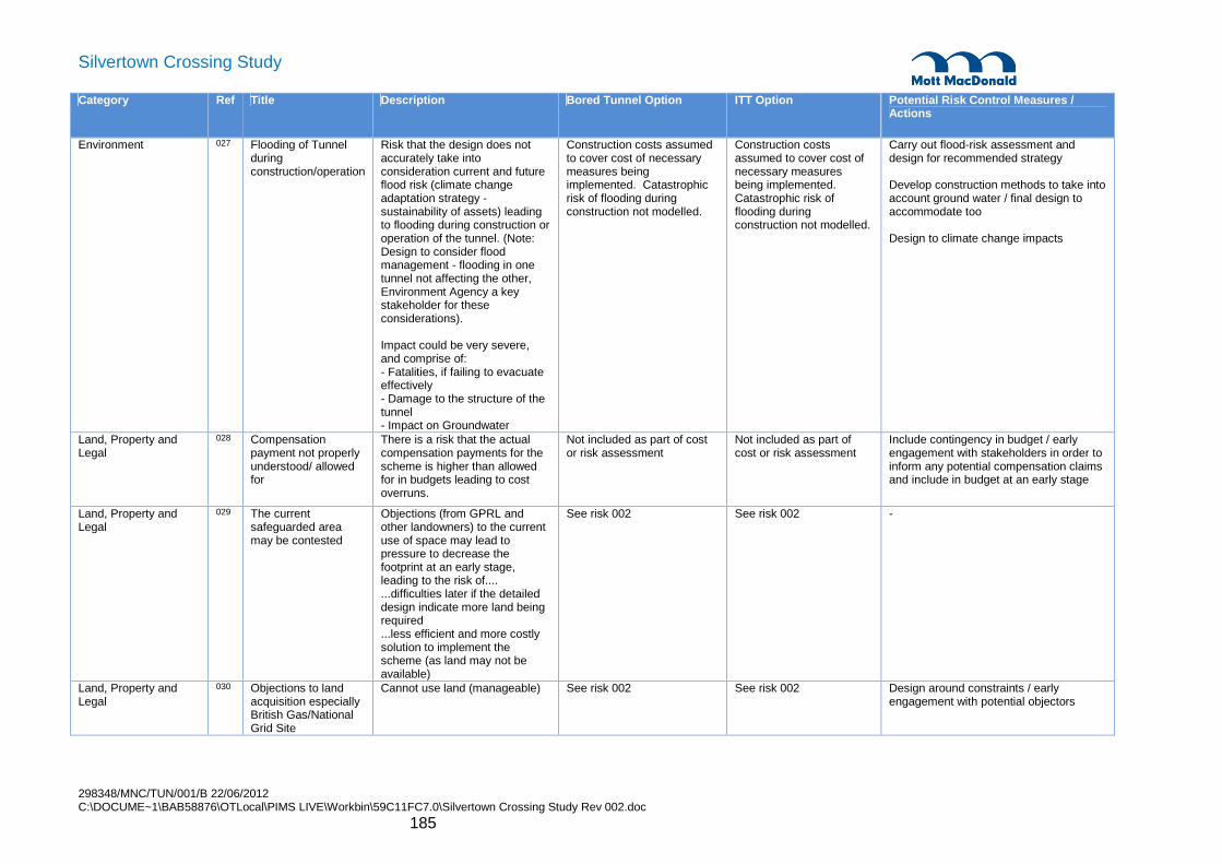
298348/MNC/TUN/001/B 22/06/2012 C:\DOCUME~1\BAB58876\OTLocal\PIMS LIVE\Workbin\59C11FC7.0\Silvertown Crossing Study Rev 002.doc
185
Silvertown Crossing Study Category Ref Title Description Bored Tunnel Option ITT Option Potential Risk Control Measures /
Actions
Environment 027 Flooding of Tunnel during construction/operation
Risk that the design does not accurately take into consideration current and future flood risk (climate change adaptation strategy - sustainability of assets) leading to flooding during construction or operation of the tunnel. (Note: Design to consider flood management - flooding in one tunnel not affecting the other, Environment Agency a key stakeholder for these considerations). Impact could be very severe, and comprise of: - Fatalities, if failing to evacuate effectively - Damage to the structure of the tunnel - Impact on Groundwater
Construction costs assumed to cover cost of necessary measures being implemented. Catastrophic risk of flooding during construction not modelled.
Construction costs assumed to cover cost of necessary measures being implemented. Catastrophic risk of flooding during construction not modelled.
Carry out flood-risk assessment and design for recommended strategy Develop construction methods to take into account ground water / final design to accommodate too Design to climate change impacts
Land, Property and Legal
028 Compensation payment not properly understood/ allowed for
There is a risk that the actual compensation payments for the scheme is higher than allowed for in budgets leading to cost overruns.
Not included as part of cost or risk assessment
Not included as part of cost or risk assessment
Include contingency in budget / early engagement with stakeholders in order to inform any potential compensation claims and include in budget at an early stage
Land, Property and Legal
029 The current safeguarded area may be contested
Objections (from GPRL and other landowners) to the current use of space may lead to pressure to decrease the footprint at an early stage, leading to the risk of.... ...difficulties later if the detailed design indicate more land being required ...less efficient and more costly solution to implement the scheme (as land may not be available)
See risk 002 See risk 002 -
Land, Property and Legal
030 Objections to land acquisition especially British Gas/National Grid Site
Cannot use land (manageable) See risk 002 See risk 002 Design around constraints / early engagement with potential objectors

298348/MNC/TUN/001/B 22/06/2012 C:\DOCUME~1\BAB58876\OTLocal\PIMS LIVE\Workbin\59C11FC7.0\Silvertown Crossing Study Rev 002.doc
186
Silvertown Crossing Study Category Ref Title Description Bored Tunnel Option ITT Option Potential Risk Control Measures /
Actions
Land, Property and Legal
031 Acquisition of and operation on construction sites
Potential CPO and delay to programme / cost
See risk 002 See risk 002 Design around constraints and liaise with land owners
Operations / Maintenance
032 Operations / Maintenance
Uncertainty in the need and scope of: - Adequate facilities - Access arrangements - Central Gallery
Facilities to be included as part of the base cost. Allow residual risk of £1-2m for the provision of additional facilities not covered for in the base costs.
Facilities to be included as part of the base cost. Allow residual risk of £1-2m for the provision of additional facilities not covered for in the base costs.
Detailed review of end user requirements
Design and Approvals 033 Risk of Blowout Risk of blowout. Need to mitigate - based on site investigations.
Very limited use of compressed air. Risk is very small. However the TBM interventions may require the use of compressed air. If it is required there a small risk (less than 1%) of problem leading to additional costs (catastrophic risk) - £10m risk (insured risk). Not modelled.
Not a risk for ITT option Carry out SI and survey Minimise the tunnel design diameter Relax constraint on alignment gradient to greater than 4% Correct TBM specification Construction control
Design and Approvals 034 Failure to Challenge Standards and/or obtain Approval for the emergency escape and intervention plan
Failure to challenge Standards (especially HA Standard BD78/99 - Road Tunnels) leads to more costly solution. LFEPA (TDSCG - Tunnel Design Safety Consultation Group) do not approve emergency escape and intervention plan
HA Standard BD78/99 - Road Tunnels indicating cross passages required every 100m. Cost estimate includes allowances to this effect. No residual risk modelled.
Not a lot of standards (risk based methodology), No risk impact modelled.
Develop relevant cross section and cost Value engineering in detailed design stage. Ongoing peer review to challenge inputs Either comply with BD78/99 in all aspects, or design using a risk-based approach and write a robust analysis (ALARP on evacuation strategy) of the safety case & present it to Fire (LFEPA) and emergency services.
Design and Approvals 035 Changes to Classification of tunnel (ADR Cat E) or hazardous loads entering the tunnel undetected
Design assumption is a ADR Cat E tunnel (hazardous materials are banned from tunnel), but risk that this classification changes and also the residual risk that hazardous loads enter the tunnel undetected (Worst case would be having to mitigate the exposure with toll booths with barriers)
No impact modelled, not believed to have a significant impact on costs (included in cost and estimating uncertainties).
No impact modelled, not believed to have a significant impact on costs (included in cost and estimating uncertainties).
Risk assessments
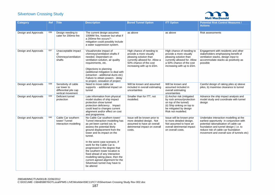
298348/MNC/TUN/001/B 22/06/2012 C:\DOCUME~1\BAB58876\OTLocal\PIMS LIVE\Workbin\59C11FC7.0\Silvertown Crossing Study Rev 002.doc
187
Silvertown Crossing Study Category Ref Title Description Bored Tunnel Option ITT Option Potential Risk Control Measures /
Actions
Design and Approvals 036 Design needing to cater for 200mw fire
The current design assumes 100MW fire, however but what if a 200mw fire occurs? - mitigation could possibly include a water suppression system.
as above as above Risk assessments
Design and Approvals 037 Unacceptable impact of Chimneys/ventilation shafts
Visual/smoke impact of chimneys/ventilation shafts if needed. Dependant on ventilation solution, air quality requirements, etc. Objections to planning (additional mitigation to deal with extraction - additional ducts etc) Failure to obtain powers - delay to project, cessation of project
High chance of needing to provide a more visually pleasing solution than currently allowed for. Allow a 50% chance of the cost increasing with up to £5m.
High chance of needing to provide a more visually pleasing solution than currently allowed for. Allow a 50% chance of the cost increasing with up to £5m.
Engagement with residents and other stakeholders emphasising benefit of ventilation stacks, design input to accommodate stacks as positively as possible
Design and Approvals 038 Sensitivity of cable car tower to differential pile cap vertical movement
Need to move cable car supports - additional impact on tunnel
Will be known and assumed included in overall estimating uncertainties
Will be known and assumed included in overall estimating uncertainties
Careful design of raking piles a) sleeve piles, b) maximise clearance to tunnel
Design and Approvals 039 Deficient tunnel protection
Late information from physical model studies of ship impact protection show tunnel protection deficiency . Impact could lead to changes current alignment and/or effect on cost and programme.
Smaller than for ITT, not modelled.
(i) Anchor risk (mitigated by rock armour/protection on top of the tunnel) (ii) Ship sinking on top to be mitigated by design Risk not modelled.
Advance the ship impact analysis and model study and coordinate with tunnel design
Design and Approvals 040 Cable Car southern tower/ Tunnel interaction modelling
No Cable Car southern tower/ Tunnel interaction modelling has as yet been carried out, to assess the potential likely ground displacement from the tower and its impact on the tunnel. In the worst case scenario, if work for the Cable Car is progressed to the degree that the southern tower location is fixed ahead of any interaction modelling taking place, then the current agreed alignment for the Silvertown tunnel may have to be altered
Issue will be known prior to more detailed design. Not assumed to have an overall detrimental impact on overall costs.
Issue will be known prior to more detailed design. Not assumed to have an overall detrimental impact on overall costs.
Undertake interaction modelling at the earliest opportunity in conjunction with potential rationalisation of cable car foundation and tunnel design ( i.e. to reduce risk of cable car foundation movement and overall size of tunnels etc)

298348/MNC/TUN/001/B 22/06/2012 C:\DOCUME~1\BAB58876\OTLocal\PIMS LIVE\Workbin\59C11FC7.0\Silvertown Crossing Study Rev 002.doc
188
Silvertown Crossing Study Category Ref Title Description Bored Tunnel Option ITT Option Potential Risk Control Measures /
Actions
Design and Approvals 041 Change in legal requirements and standards
Change in legal requirements and standards may require revisiting the design. Delay in programme and increase in cost (could happen during or after design being finalised)
Allow a 5% chance of additional costs of up to £1m.
Allow a 5% chance of additional costs of up to £1m.
Monitoring of changes to legal requirements and standards
Design and Approvals 042 Connection to network need to consider Green Wave
Cannot achieve it, leading to the need for bigger geometry.
No longer an issue with current design assumptions
No longer an issue with current design assumptions
-
Design and Approvals 043 Traffic Congestion / Extraction System
Could lead to structural changes / bigger geometry
Included in design and cost Included in design and cost
-
Design and Approvals 044 Requirements for processing of drainage water
Risk of additional costs for facilities to process/deal with drainage water (including land take)
Included in design and cost Included in design and cost
-
Design and Approvals 045 Changes to key design Parameters
Changes arising from further ground investigations, boreholes etc.
Covered in high level estimating uncertainties
Covered in high level estimating uncertainties
Risk workshops / Review
Ground Conditions 046 Contaminated spoil Increased cost in disposing of spoil Contamination of other land or water
Allow increased cost for contaminated material at a 50/50 chance with an impact of £250k to £1000k.
Allow increased cost for contaminated material at a 50/50 chance with an impact of £250k to £1500k.
Detailed advance site investigation focussing on likely hot spots and ensuring general coverage of excavated areas
Ground Conditions 047 Hard layers (including flint bands) and inclusions in Lambeth Group soils
Interruption of construction Covered in costing approach and overall uncertainties..
Covered in costing approach and overall uncertainties..
TBM needs to accommodate for this
Ground Conditions 048 Obstructions whilst piling (secant piles)
Hitting obstruction leading to overall delays of the works
Covered in estimating uncertainties for the relevant works.
Covered in estimating uncertainties for the relevant works.
Plan for interventions
Ground Conditions 049 Risk of collapse and settlement impact whilst doing the works
Risk of collapse to the tunnel whilst doing the works and also potential settlement impact on (weakening/collapse) the cable car foundations , rivers walls, tie back anchors and buildings.
Catastrophic risks not modelled Allow a risk of needing to provide mitigation measures (e.g. DLR, Cable Car, River Walls, and buildings). Allow a 20% of £50k to £2000k.
Catastrophic risks not modelled Allow a risk of needing to provide mitigation measures (e.g. DLR, Cable Car, River Walls, and buildings). Allow a 20% of £50k to £2000k.
Model effects and accommodate requirements in design or revise layout

298348/MNC/TUN/001/B 22/06/2012 C:\DOCUME~1\BAB58876\OTLocal\PIMS LIVE\Workbin\59C11FC7.0\Silvertown Crossing Study Rev 002.doc
189
Silvertown Crossing Study Category Ref Title Description Bored Tunnel Option ITT Option Potential Risk Control Measures /
Actions
Ground Conditions 050 PLA Maintenance Dredging of river
Risk that maintenance dredging will reduce the tunnel crown cover to less than acceptable levels.
Risk regarded as low, and consultation needs to be held with PLA on regime. Not additional impact modelled.
Not a risk for ITT option Liaison with PLA Dredging restrictions Ensure sufficient cover to start with
Ground Conditions 051 Vessel sinking on tunnel
Weakening of tunnel / damage to tunnel
See above See above Risk assessment and accommodate likely loading in tunnel design
Enabling Works 052 Diversion of existing utilities
Uncertainty in the scope of utility diversions required and in addition risk of damage to utilities during construction, causing delay to programme (normal utilities but also drainage outfalls at Royal Docks)
High level estimating uncertainty for main diversion works, allow residual risk at 20% of additional costs of up to £1m.
High level estimating uncertainty for main diversion works, allow residual risk at 20% of additional costs of up to £1m.
Undertake investigations to locate utilities, engage with utilities providers, devise utilities management plan
Enabling Works 053 Unexploded Ordnance
Addition of cost (timescales) to the scheme in order to safely dispose of any explosive devices found in the area impacted by the tunnel construction
Assumed covered in high level estimating uncertainties for the scheme.
Assumed covered in high level estimating uncertainties for the scheme.
Undertake GI at the earliest opportunity, to reduce the risk of any implications on the project Detailed risk assessment in situ investigations prior to ground investigation and construction works
Construction 054 Terrorism and crime Mitigation measures (increased cost of security) Drivers getting harmed in tunnel Damage to tunnel structure
Not modelled at this stage. Not modelled at this stage. Consulting with BT Police and other key stakeholders for safety input
Construction 055 Uncertainty in the cost estimates
Change in cost e.g. material and human resources, interest rates etc
See separate exercise. See separate exercise. Include contingency in budget
Construction 057 Amount of River Closures required
There is an uncertainty in how many river closures would be required to do the works. Currently it is assumed that about 5 weekend closures would be required for the immersed tunnel option. Additional cost for additional closures, also risk of rejection/delays if late changes are required (e.g. The identification of more closures at a later date, or failure to utilise existing possessions)
Not required Covered in the estimating uncertainty of the cost of Floating and Positioning the submerged units.
Review of construction method

298348/MNC/TUN/001/B 22/06/2012 C:\DOCUME~1\BAB58876\OTLocal\PIMS LIVE\Workbin\59C11FC7.0\Silvertown Crossing Study Rev 002.doc
190
Silvertown Crossing Study Category Ref Title Description Bored Tunnel Option ITT Option Potential Risk Control Measures /
Actions
Construction 058 Limited constricted road access for transport of TBM to launch site
Interruption of construction Not an issue with current assumptions
Not applicable Detailed checking of routes and initiation of improvements if deemed necessary
Construction 059 Blackwall tunnel not able to accommodate transport of large TBM components
Old Blackwall tunnel cannot accommodate transport of large TBM components for 2nd drive from Silvertown. Increased cost and delay on programme
Not an issue with current assumptions, TBM will rotate for the second drive. The reason for this is the difficulty in transporting and disassembling the TBM.
Not applicable Construct TBM turn around chamber at O2 Transfer TBM by barge across river from temporary wharves Use QE2 bridge at Dartford, implement a closure and transport TBM northbound over the bridge.
Construction 060 Restrictions on Road and river traffic
Increased costs and limitations (storing on site) Compensation to LB (heavy vehicles) or restrictions
See traffic management risk See traffic management risk
Construction traffic impact assessment and phasing plan
Construction 061 High Voltage Facilities
Needs to be upgraded. Adequate TBM site electricity assumed in the basic cost estimate and no additional risk modelled.
No additional cost risk modelled.
To be addressed at detailed design stage
Construction 062 Fire/Toxic Spill during construction
- Adequate suppression systems will be included in the cost estimates.
Adequate suppression systems will be included in the cost estimates.
Review suppression systems at later design stage

298348/MNC/TUN/001/B 22/06/2012 C:\DOCUME~1\BAB58876\OTLocal\PIMS LIVE\Workbin\59C11FC7.0\Silvertown Crossing Study Rev 002.doc
191
Silvertown Crossing Study
Appendix E. CFD Modelling
E.1. Introduction
Computational Fluid Dynamics (CFD) modelling has been undertaken to assess conditions within the tunnel in the event of a fire incident. The analysis was carried out using the Fire Dynamics Simulator (FDS) program, version 5.5, developed by the US National Institute of Standards and Technology (NIST). The software solves numerically a form of the Navier-Stokes equations appropriate for low speed, thermally-driven flow with a Large Eddy Simulation (LES) model for turbulence, there is an emphasis on smoke and heat transport from fires. The combustion is modelled through a single step chemical reaction and its products are tracked with a two-parameter mixture fraction model. A radiative transport model is also included. By calculation of the soot and carbon monoxide concentration of the smoke air as it is discharged from the fire, it is possible to evaluate these concentrations throughout the domain. FDS is a de facto worldwide standard tool for simulation of fire growth and spread and has been extensively validated. The FDS User Guide and Technical Reference Guide (NIST, 2010) provide further information and examples of validation.
E.2. Model Geometry
The CFD model represents a 600m long section of the Silvertown tunnel. The fire is located at the bottom of the entry ramp (approximately 400m from the Silvertown entrance portal). This corresponds to the worst case in terms of the potential for smoke back-layering. Figure E.1 and Figure E.2 show the domain used.
The applicability of FDS for modelling road tunnel fires, and the sensitivity to grid size, was demonstrated by Cheong Mun Kit (University of Canterbury, 2009) “Assessment of Vehicle Fire Development in Road Tunnels for Smoke Control Ventilation Design”. It was concluded that “using a grid size of 300 mm for the simulations was appropriate”, giving “fairly consistent predictions in terms of the growth phase of the fire development as compared with the actual fire experiment” and “closer resemblance in terms of peak HRR and fire curve as compared with 150 mm grid size”.
E.2.1. Bored Tunnel
The domain is split into four blocks; within the block of interest (i.e. the block housing the fire) the cell dimension is 0.25m in all directions. In the other three blocks the cell dimension is 0.5m in the x and y directions and 0.25m in the z direction. This creates a multi-block fluid domain consisting of approximately 1.1 million cells. Larger cells are justified away from the incident because these areas do not require as high a level of accuracy. By increasing the cell size away from the area of interest, the computational time can be reduced. The grid sizing adopted for the analysis is considered to be reasonable in the context of the relatively large dimensions of the fire and the large size of the computational domain, allowing for efficient computation of a solution of reasonable accuracy.

298348/MNC/TUN/001/B 22/06/2012 C:\DOCUME~1\BAB58876\OTLocal\PIMS LIVE\Workbin\59C11FC7.0\Silvertown Crossing Study Rev 002.doc
192
Silvertown Crossing Study
Figure E.1: Overview of CFD model for the bored tunnel
E.2.2. Immersed Tube Tunnel
As for the bored tunnel, the domain is split into four blocks; within the block of interest (i.e. the block housing the fire) the cell dimension is 0.25m in all directions. In the other three blocks the cell dimension is 0.5m in the x and y directions and 0.25m in the z direction. The domain comprises a total of approximately 780,000 cells.
Figure E.2: Overview of CFD model for the immersed tube tunnel
Truncated end x = 600m
Silvertown entrance portal
x = 0m
Fire location x = 400m
Downhill Normal traffic
direction
Downhill Normal traffic
direction Fire location x = 400m
Silvertown entrance portal
x = 0m
Truncated end x = 600m

298348/MNC/TUN/001/B 22/06/2012 C:\DOCUME~1\BAB58876\OTLocal\PIMS LIVE\Workbin\59C11FC7.0\Silvertown Crossing Study Rev 002.doc
193
Silvertown Crossing Study
E.3. Fire Source Properties
The fire modelling requires input values for heat of combustion, smoke yield and CO yield. An indicative estimate of these properties based on an assumed composition of a truck and its load and calculating mass-weighted average rates, as presented in Table E.1.
Table E.1: Estimated carbon monoxide and smoke yields from a burning HGV
Material Mass (kg) Heat of Combustion
(MJ/kg)
Smoke yield (kg/kg)
CO yield (kg/kg)
Cab Polyethylene 80 44 0.060 0.024
Polyurethane foam 25 26 0.198 0.042
Fuel Diesel 50 41 0.059 0.019
Tyres Rubber 600 32 0.114 0.021
Flooring Wood 600 18 0.015 0.004
Load Cardboard 1000 17 0.015 0.004
PVC 1000 17 0.172 0.063
Polystyrene 1000 40 0.164 0.06
Mass-weighted average values 25.3 0.101 0.034
Source: SFPE & BS7974
E.4. Boundary Conditions
For both the bored and immersed tunnel models the walls are represented by insulated concrete with a thickness of 1m.
From the time of detection, the overall tunnel ventilation air flow has been ramped up from 0 m/s to 3.0 m/s over 5 minutes.
E.5. Tenability Criteria
A fundamental aspect of using fire modelling is the assessment of tenability. A tenable environment is one in which hazardous conditions are limited to a level that is not life threatening and supports the safe evacuation of passengers. Tenability is generally assessed in terms of visibility, local air temperature, the radiant heat flux from the fire and hot smoke layer, and the carbon monoxide concentration. Tenability criteria for this engineering analysis have been referenced from PD 7974-6: ‘Human factors: Life safety strategies – Occupant evacuation, behaviour and condition (Sub-system 6), The application of fire safety engineering principles to fire safety design of buildings’ (2004). The following criteria will be used to assess tenability at a height of 2m above the road surface.
Conditions at a given location are considered untenable if the visibility deteriorates to 10m.
Conditions at a given location are considered untenable if the local temperature exceeds 60ºC, which corresponds to the maximum air temperature that air can be before it causes damage to the lungs and internal airways of a person.

298348/MNC/TUN/001/B 22/06/2012 C:\DOCUME~1\BAB58876\OTLocal\PIMS LIVE\Workbin\59C11FC7.0\Silvertown Crossing Study Rev 002.doc
194
Silvertown Crossing Study
The tenability limit for exposure of skin to radiant heat is 2.5 kW/m². Below this incident heat flux level, exposure can be tolerated for several minutes. Conditions are also considered untenable due to the effects of radiant heat if the temperature of the hot gas layer directly above is greater than approximately 200°C.
The toxic products of combustion can be irritant and narcotic components which can cause disorientation, incapacitation or death depending on the concentration and length of exposure. Carbon monoxide (CO) concentrations are considered tenable provided they do not exceed 1200 ppm for 5 minutes exposure and 275 ppm for 30 minute exposure.

298348/MNC/TUN/001/B 22/06/2012 C:\DOCUME~1\BAB58876\OTLocal\PIMS LIVE\Workbin\59C11FC7.0\Silvertown Crossing Study Rev 002.doc
195
Silvertown Crossing Study
Appendix F. Minutes of Meetings

298348/MNC/TUN/001/B 22/06/2012 C:\DOCUME~1\BAB58876\OTLocal\PIMS LIVE\Workbin\59C11FC7.0\Silvertown Crossing Study Rev 002.doc
196
Silvertown Crossing Study

298348/MNC/TUN/001/B 22/06/2012 C:\DOCUME~1\BAB58876\OTLocal\PIMS LIVE\Workbin\59C11FC7.0\Silvertown Crossing Study Rev 002.doc
197
Silvertown Crossing Study

298348/MNC/TUN/001/B 22/06/2012 C:\DOCUME~1\BAB58876\OTLocal\PIMS LIVE\Workbin\59C11FC7.0\Silvertown Crossing Study Rev 002.doc
198
Silvertown Crossing Study

298348/MNC/TUN/001/B 22/06/2012 C:\DOCUME~1\BAB58876\OTLocal\PIMS LIVE\Workbin\59C11FC7.0\Silvertown Crossing Study Rev 002.doc
199
Silvertown Crossing Study

298348/MNC/TUN/001/B 22/06/2012 C:\DOCUME~1\BAB58876\OTLocal\PIMS LIVE\Workbin\59C11FC7.0\Silvertown Crossing Study Rev 002.doc
200
Silvertown Crossing Study

298348/MNC/TUN/001/B 22/06/2012 C:\DOCUME~1\BAB58876\OTLocal\PIMS LIVE\Workbin\59C11FC7.0\Silvertown Crossing Study Rev 002.doc
201
Silvertown Crossing Study

298348/MNC/TUN/001/B 22/06/2012 C:\DOCUME~1\BAB58876\OTLocal\PIMS LIVE\Workbin\59C11FC7.0\Silvertown Crossing Study Rev 002.doc
202
Silvertown Crossing Study

298348/MNC/TUN/001/B 22/06/2012 C:\DOCUME~1\BAB58876\OTLocal\PIMS LIVE\Workbin\59C11FC7.0\Silvertown Crossing Study Rev 002.doc
203
Silvertown Crossing Study

298348/MNC/TUN/001/B 22/06/2012 C:\DOCUME~1\BAB58876\OTLocal\PIMS LIVE\Workbin\59C11FC7.0\Silvertown Crossing Study Rev 002.doc
204
Silvertown Crossing Study
Following the meeting with PLA on 23rd January 2012 the following email was received confirming their input:
From: Trimmer, James [[email protected]] Sent: 21 February 2012 18:35
To: Baber, Jonathan Cc: Lawrence, Terry; Jenkins, Nicola
Subject: Proposed Silvertown Crossing
Jonathan
Further to our recent meeting and subsequent e-mails; and with apologies for the delay in responding to
you, I have consulted internally on the proposed approach to an immersed tube tunnel.
In broad terms, we would not immediately discount the approach you described at the meeting and
subsequently by e-mail as being unworkable, particularly if the proposed dredging works extended to tackle
the ends of the Blackwall Shoal. Dredging works would need to be undertaken during the winter months to
avoid the cruise season, although I understand that this is preferred in any event due to environmental
constraints. Other movements of large ships (I am assuming that these works would be undertaken in the
context of reactivated wharves at both Peruvian and Orchard, although with Crossrail spoil having finished)
could be managed by the lifting of the spud legs and temporary moving of the dredger for the duration of
the vessel's passing, but we would work on the basis that the passage of ships was prioritised.
Having discussed the idea briefly with river users (and I would reiterate that these were brief discussions),
the prospect of weekend closures may well disrupt regular passenger and freight services, but if planned
properly and well in advance should be able to be accommodated. Again, any such closures would
preferably be undertaken during the winter months.
The Harbour Master comments that, on the basis that a comparable methodology was used on the Tyne,
he'd like the opportunity to discuss the various issues with his counterpart were this proposal to proceed to
a more detailed consideration. You will be aware that the PLA would seek to ensure that the use of the
river was maximised in relation to the construction and its associated logistics.
You will appreciate that the assessment for such a dredging operation will be both complex and thorough.
It is likely that there will be detailed restrictions on timing in relation to monitoring, particularly for oxygen
levels and suspended solids in the water column. These conditions are currently in place for (admittedly far
larger) dredging operation at London Gateway.
I trust that this is sufficient for your purposes at the moment; you will appreciate that these are the PLA's
preliminary thoughts on the matter from the information we have received.
All the best

298348/MNC/TUN/001/B 22/06/2012 C:\DOCUME~1\BAB58876\OTLocal\PIMS LIVE\Workbin\59C11FC7.0\Silvertown Crossing Study Rev 002.doc
205
Silvertown Crossing Study
Jim
James Trimmer
Head of Planning and Partnerships
Port of London Authority
London River House
Royal Pier Road
Gravesend
Kent DA12 2BG
D/L - 01474 562380
Fax - 01474 562398
Mob - 07713 654595
www.pla.co.uk

298348/MNC/TUN/001/B 22/06/2012 C:\DOCUME~1\BAB58876\OTLocal\PIMS LIVE\Workbin\59C11FC7.0\Silvertown Crossing Study Rev 002.doc
206
Silvertown Crossing Study
Reports
1. New Thames River Crossing, Silvertown Tunnel Option – Volume 1, Rev 001, dated 30th November 2009. Mott MacDonald.
2. New Thames River Crossing, Silvertown Tunnel Option – Addendum to Volume 1, Rev 1.0, dated 7th October 2010. Mott MacDonald.
3. New Thames River Crossing, Silvertown Tunnel Option – Alignment Development, Rev 1.0, dated 10th January 2011. Mott MacDonald.
4. Geotechnical Desk Study, Report for the New Thames River Crossings, Revision A dated 5th October 2010
5. Some borehole data was based upon records provided by British Geological Survey (NERC). http://www.bgs.ac.uk/data/boreholescans/ (Jan 2012)
Drawings
1. Landscape Master plan drawing 2338/LD/001 Rev 0. Battle McCarthy Landscape Architects.
2. Greenwich Peninsula Cable Car Area Masterplan, DEW 7C PA – 03-150.
3. Cable Profile, Cable Profile and Tower Heights, 001-AR –AED-DWG-0601010- Rev 10.
4. North Station (Drive Station), Site Plan, 002-AR-AED-DWG-0601021 - Rev 8.
5. North Station, Kiosk and Substation Buildings, 002-AR-AED-DWG-0601125 –Rev 7.
6. North Station & North Compression Tower, Pile layout & Reference Table, 002-CS-URS-DWG-0200011 – Rev 10.
7. Ship Impact protection System, North Drive Station, General Arrangement, 002-SI-RHG-DWG-9900100 – Rev P7.
8. South Station (Return Station), Site Plan – 003-AR-AED-DWG-0601031 – Rev 7.
9. South Station & South Compression Tower, Pile Layout & reference table, 003-CS-URS-DWG-0200101 – Rev 9.
10. North Tower, Foundation General Arrangement, 004-C5-BHD-DWG-0300002- Rev C2.
Appendix G. Reference Documents
298348/MNC/TUN/001/B 22/06/2012 C:\DOCUME~1\BAB58876\OTLocal\PIMS LIVE\Workbin\59C11FC7.0\Silvertown Crossing Study Rev 002.doc
207
Silvertown Crossing Study
11. South Tower, Foundation General Arrangement, 005-CS-BHD-DWG-0300002- Rev P2.
12. North Intermediate Tower, Foundation General Arrangement, 006-CS-BHD-DWG-0300002 – Rev P3.
13. HA-BRG-PWD-DRG-10020 Rev X0 – Viaduct Spans Layout Plan & Elevation Sheet - 1 of 10
14. HA-BRG-PWD-DRG-15000 Rev X0 – Substructure Information Tables Piers Sheet 1 of 2
15. HA-BRG-PWD-DRG-15005 Rev X0 – Viaduct Pile-caps General Arrangement Sheet 1 of 3
16. HA-BRG-PWD-DRG-15006 Rev X0 – Viaduct Pile-caps General Arrangement Sheet 2 of 3
17. HA-BRG-PWD-DRG-15200 Rev X0 – Substructures Pile Reinforcement 30m CFA Pile Option