risk management program guidance for offsite ... guidance for offsite consequence analysis printed...
TRANSCRIPT

United States Office of Solid Waste EPA 550-B-99-009Environmental Protection and Emergency Response April 1999Agency (5104) www.epa.gov/ceppo/
Chemical Emergency Preparedness and Prevention Office
RM
P SE
RIE
SRISK MANARISK MANARISK MANARISK MANARISK MANAGEMENTGEMENTGEMENTGEMENTGEMENTPROGRAM GUIDPROGRAM GUIDPROGRAM GUIDPROGRAM GUIDPROGRAM GUIDANCEANCEANCEANCEANCEFOR OFFSITEFOR OFFSITEFOR OFFSITEFOR OFFSITEFOR OFFSITECONSEQUENCECONSEQUENCECONSEQUENCECONSEQUENCECONSEQUENCEANALANALANALANALANALYSISYSISYSISYSISYSIS
Printed on recycled paper

This document provides guidance to the owner or operator of processes covered by the Chemical AccidentPrevention Program rule in the analysis of offsite consequences of accidental releases of substances regulatedunder section 112(r) of the Clean Air Act. This document does not substitute for EPA's regulations, nor is ita regulation itself. Thus, it cannot impose legally binding requirements on EPA, States, or the regulatedcommunity, and may not apply to a particular situation based upon the circumstances. This guidance doesnot constitute final agency action, and EPA may change it in the future, as appropriate.

iApril 15, 1999
TABLE OF CONTENTSChapter Page
Table of Potentially Regulated Entities . . . . . . . . . . . . . . . . . . . . . . . . . . . . . . . . . . . . . . . . . . . .viiiRoadmap to Offsite Consequence Analysis Guidance by Type of Chemical . . . . . . . . . . . . . . . . . . x
1 Introduction . . . . . . . . . . . . . . . . . . . . . . . . . . . . . . . . . . . . . . . . . . . . . . . . . . . . . . . . . . . . . . . . . . . 1- 1
1.1 Purpose of this Guidance. . . . . . . . . . . . . . . . . . . . . . . . . . . . . . . . . . . . . . . . . . . . . . . . . . 1-11.2 This Guidance Compared to Other Models. . . . . . . . . . . . . . . . . . . . . . . . . . . . . . . . . . . . 1-41.3 Number of Scenarios to Analyze . . . . . . . . . . . . . . . . . . . . . . . . . . . . . . . . . . . . . . . . . . . . 1-41.4 Modeling Issues. . . . . . . . . . . . . . . . . . . . . . . . . . . . . . . . . . . . . . . . . . . . . . . . . . . . . . . . . 1-51.5 Steps for Performing the Analysis. . . . . . . . . . . . . . . . . . . . . . . . . . . . . . . . . . . . . . . . . . . 1-6
1.5.1 Worst-Case Analysis for Toxic Gases. . . . . . . . . . . . . . . . . . . . . . . . . . . . . . . . . 1-71.5.2 Worst-Case Analysis for Toxic Liquids . . . . . . . . . . . . . . . . . . . . . . . . . . . . . . . . 1-71.5.3 Worst-Case Analysis for Flammable Substances. . . . . . . . . . . . . . . . . . . . . . . . 1-81.5.4 Alternative Scenario Analysis for Toxic Gases . . . . . . . . . . . . . . . . . . . . . . . . . . 1-81.5.5 Alternative Scenario Analysis for Toxic Liquids. . . . . . . . . . . . . . . . . . . . . . . . . 1-91.5.6 Alternative Scenario Analysis for Flammable Substances. . . . . . . . . . . . . . . . . . 1-9
1.6 Additional Sources of Information. . . . . . . . . . . . . . . . . . . . . . . . . . . . . . . . . . . . . . . . . . 1-10
2 Determining Worst-Case Scenario. . . . . . . . . . . . . . . . . . . . . . . . . . . . . . . . . . . . . . . . . . . . . . . . . 2-1
2.1 Definition of Worst-Case Scenario. . . . . . . . . . . . . . . . . . . . . . . . . . . . . . . . . . . . . . . . . . 2-12.2 Determination of Quantity for the Worst-Case Scenario. . . . . . . . . . . . . . . . . . . . . . . . . . 2-32.3 Selecting Worst-Case Scenarios. . . . . . . . . . . . . . . . . . . . . . . . . . . . . . . . . . . . . . . . . . . . . 2-3
3 Release Rates for Toxic Substances. . . . . . . . . . . . . . . . . . . . . . . . . . . . . . . . . . . . . . . . . . . . . . . . 3-1
3.1 Release Rates for Toxic Gases . . . . . . . . . . . . . . . . . . . . . . . . . . . . . . . . . . . . . . . . . . . . . . 3-13.1.1 Unmitigated Releases of Toxic Gas . . . . . . . . . . . . . . . . . . . . . . . . . . . . . . . . . . . 3-23.1.2 Releases of Toxic Gas in Enclosed Space . . . . . . . . . . . . . . . . . . . . . . . . . . . . . . 3-23.1.3 Releases of Liquefied Refrigerated Toxic Gas in Diked Area. . . . . . . . . . . . . . . 3-3
3.2 Release Rates for Toxic Liquids. . . . . . . . . . . . . . . . . . . . . . . . . . . . . . . . . . . . . . . . . . . . 3-43.2.1 Releases of Toxic Liquids from Pipes. . . . . . . . . . . . . . . . . . . . . . . . . . . . . . . . . 3-53.2.2 Unmitigated Releases of Toxic Liquids. . . . . . . . . . . . . . . . . . . . . . . . . . . . . . . . 3-53.2.3 Releases of Toxic Liquids with Passive Mitigation. . . . . . . . . . . . . . . . . . . . . . . 3-73.2.4 Mixtures Containing Toxic Liquids. . . . . . . . . . . . . . . . . . . . . . . . . . . . . . . . . . 3-113.2.5 Release Rate Correction for Toxic Liquids Released at Temperatures
Between 25 C and 50 C . . . . . . . . . . . . . . . . . . . . . . . . . . . . . . . . . . . . . . . . . . 3-12o o
3.3 Release Rates for Common Water Solutions of Toxic Substances and for Oleum. . . . . 3-14
4 Estimation of Worst-Case Distance to Toxic Endpoint . . . . . . . . . . . . . . . . . . . . . . . . . . . . . . . . . 4-1

TABLE OF CONTENTS(Continued)
Chapter Page
iiApril 15, 1999
5 Estimation of Distance to Overpressure Endpoint for Flammable Substances. . . . . . . . . . . . . . . 5-1
5.1 Flammable Substances Not in Mixtures. . . . . . . . . . . . . . . . . . . . . . . . . . . . . . . . . . . . . . 5-15.2 Flammable Mixtures . . . . . . . . . . . . . . . . . . . . . . . . . . . . . . . . . . . . . . . . . . . . . . . . . . . . . 5-2
Reference Tables of Distances for Worst-Case Scenarios. . . . . . . . . . . . . . . . . . . . . . . . . . . . . . . 5-4 Table
Neutrally Buoyant Plume Distances to Toxic Endpoint for Release Rate Divided byEndpoint, F Stability, Wind Speed 1.5 Meters per Second:
1 10-Minute Release, Rural Conditions. . . . . . . . . . . . . . . . . . . . . . . . . . . . . . . . . . . . . . . . 5-42 60-Minute Release, Rural Conditions. . . . . . . . . . . . . . . . . . . . . . . . . . . . . . . . . . . . . . . . 5-53 10-Minute Release, Urban Conditions. . . . . . . . . . . . . . . . . . . . . . . . . . . . . . . . . . . . . . . . 5-64 60-Minute Release, Urban Conditions. . . . . . . . . . . . . . . . . . . . . . . . . . . . . . . . . . . . . . . . 5-7
Dense Gas Distances to Toxic Endpoint, F Stability, Wind Speed 1.5 Meters per Second:5 10-Minute Release, Rural Conditions. . . . . . . . . . . . . . . . . . . . . . . . . . . . . . . . . . . . . . . . 5-86 60-Minute Release, Rural Conditions. . . . . . . . . . . . . . . . . . . . . . . . . . . . . . . . . . . . . . . . 5-97 10-Minute Release, Urban Conditions. . . . . . . . . . . . . . . . . . . . . . . . . . . . . . . . . . . . . . . 5-108 60-Minute Release, Urban Conditions. . . . . . . . . . . . . . . . . . . . . . . . . . . . . . . . . . . . . . . 5-11
Chemical-Specific Distances to Toxic Endpoint, Rural and Urban Conditions, F Stability,Wind Speed 1.5 Meters per Second:
9 Anhydrous Ammonia Liquefied Under Pressure. . . . . . . . . . . . . . . . . . . . . . . . . . . . . . . 5-1210 Non-liquefied Ammonia, Ammonia Liquefied by Refrigeration, or Aqueous
Ammonia . . . . . . . . . . . . . . . . . . . . . . . . . . . . . . . . . . . . . . . . . . . . . . . . . . . . . . . . . . . . . 5-1311 Chlorine . . . . . . . . . . . . . . . . . . . . . . . . . . . . . . . . . . . . . . . . . . . . . . . . . . . . . . . . . . . . . . 5-1412 Sulfur Dioxide (Anhydrous). . . . . . . . . . . . . . . . . . . . . . . . . . . . . . . . . . . . . . . . . . . . . . . 5-15
Vapor Cloud Explosion Distances for Flammable Substances:13 Distance to Overpressure of 1.0 psi for Vapor Cloud Explosions
of 500 - 2,000,000 Pounds of Regulated Flammable Substances. . . . . . . . . . . . . . . . . . 5-16
6 Determining Alternative Release Scenarios. . . . . . . . . . . . . . . . . . . . . . . . . . . . . . . . . . . . . . . . . . . 6-1
7 Estimation of Release Rates for Alternative Scenarios for Toxic Substances. . . . . . . . . . . . . . . . 7-1
7.1 Release Rates for Toxic Gases . . . . . . . . . . . . . . . . . . . . . . . . . . . . . . . . . . . . . . . . . . . . . . 7-17.1.1 Unmitigated Releases of Toxic Gases . . . . . . . . . . . . . . . . . . . . . . . . . . . . . . . . . 7-17.1.2 Mitigated Releases of Toxic Gases . . . . . . . . . . . . . . . . . . . . . . . . . . . . . . . . . . . 7-4

TABLE OF CONTENTS(Continued)
Chapter Page
iiiApril 15, 1999
7.2 Release Rates for Toxic Liquids. . . . . . . . . . . . . . . . . . . . . . . . . . . . . . . . . . . . . . . . . . . . 7-67.2.1 Liquid Release Rate and Quantity Released for Unmitigated Releases. . . . . . . . 7-77.2.2 Liquid Release Rate and Quantity Released for Mitigated Releases. . . . . . . . . 7-107.2.3 Evaporation Rate from Liquid Pool. . . . . . . . . . . . . . . . . . . . . . . . . . . . . . . . . . 7-107.2.4 Common Water Solutions and Oleum. . . . . . . . . . . . . . . . . . . . . . . . . . . . . . . . 7-14
8 Estimation of Distance to the Endpoint for Alternative Scenarios for Toxic Substances. . . . . . . 8-1
9 Estimation of Release Rates for Alternative Scenarios for Flammable Substances. . . . . . . . . . . . 9-1
9.1 Flammable Gases . . . . . . . . . . . . . . . . . . . . . . . . . . . . . . . . . . . . . . . . . . . . . . . . . . . . . . . . 9-19.2 Flammable Liquids. . . . . . . . . . . . . . . . . . . . . . . . . . . . . . . . . . . . . . . . . . . . . . . . . . . . . . . 9-2
10 Estimation of Distance to the Endpoint for Alternative Scenarios for Flammable Substances. . . . . . . . . . . . . . . . . . . . . . . . . . . . . . . . . . . . . . . . . . . . . . . . . . . . . . . . . . . . . . . . . . . 10-1
10.1 Vapor Cloud Fires. . . . . . . . . . . . . . . . . . . . . . . . . . . . . . . . . . . . . . . . . . . . . . . . . . . . . . 10-110.2 Pool Fires. . . . . . . . . . . . . . . . . . . . . . . . . . . . . . . . . . . . . . . . . . . . . . . . . . . . . . . . . . . . . 10-510.3 BLEVEs . . . . . . . . . . . . . . . . . . . . . . . . . . . . . . . . . . . . . . . . . . . . . . . . . . . . . . . . . . . . . . 10-610.4 Vapor Cloud Explosion. . . . . . . . . . . . . . . . . . . . . . . . . . . . . . . . . . . . . . . . . . . . . . . . . . 10-6
Reference Tables of Distances for Alternative Scenarios . . . . . . . . . . . . . . . . . . . . . . . . . . . . . . . 10-9 Table Neutrally Buoyant Plume Distances to Toxic Endpoint for Release Rate Divided by
Endpoint, D Stability, Wind Speed 3.0 Meters per Second:14 10-Minute Release, Rural Conditions. . . . . . . . . . . . . . . . . . . . . . . . . . . . . . . . . . . . . . . 10-915 60-Minute Release, Rural Conditions. . . . . . . . . . . . . . . . . . . . . . . . . . . . . . . . . . . . . . 10-1016 10-Minute Release, Urban Conditions. . . . . . . . . . . . . . . . . . . . . . . . . . . . . . . . . . . . . . 10-1117 60-Minute Release, Urban Conditions. . . . . . . . . . . . . . . . . . . . . . . . . . . . . . . . . . . . . . 10-12
Dense Gas Distances to Toxic Endpoint, D Stability, Wind Speed 3.0 Meters per Second:18 10-Minute Release, Rural Conditions. . . . . . . . . . . . . . . . . . . . . . . . . . . . . . . . . . . . . . 10-1319 60-Minute Release, Rural Conditions. . . . . . . . . . . . . . . . . . . . . . . . . . . . . . . . . . . . . . 10-1420 10-Minute Release, Urban Conditions. . . . . . . . . . . . . . . . . . . . . . . . . . . . . . . . . . . . . . 10-1521 60-Minute Release, Urban Conditions. . . . . . . . . . . . . . . . . . . . . . . . . . . . . . . . . . . . . . 10-16

TABLE OF CONTENTS(Continued)
Chapter Page
ivApril 15, 1999
TableChemical-Specific Distances to Toxic Endpoint, D Stability, Wind Speed 3.0 Meters perSecond:
22 Anhydrous Ammonia Liquefied Under Pressure. . . . . . . . . . . . . . . . . . . . . . . . . . . . . . 10-1723 Non-liquefied Ammonia, Ammonia Liquefied by Refrigeration, or Aqueous
Ammonia . . . . . . . . . . . . . . . . . . . . . . . . . . . . . . . . . . . . . . . . . . . . . . . . . . . . . . . . . . . . 10-1824 Chlorine . . . . . . . . . . . . . . . . . . . . . . . . . . . . . . . . . . . . . . . . . . . . . . . . . . . . . . . . . . . . . 10-1925 Sulfur Dioxide (Anhydrous). . . . . . . . . . . . . . . . . . . . . . . . . . . . . . . . . . . . . . . . . . . . . . 10-20
Neutrally Buoyant Plume Distances to Lower Flammability Limit (LFL) for Release RateDivided by LFL:
26 Rural Conditions, D Stability, Wind Speed 3.0 Meters per Second. . . . . . . . . . . . . . . 10-2127 Urban Conditions, D Stability, Wind Speed 3.0 Meters per Second. . . . . . . . . . . . . . . 10-21
Dense Gas Distances to Lower Flammability Limit:28 Rural Conditions, D Stability, Wind Speed 3.0 Meters per Second. . . . . . . . . . . . . . . 10-2229 Urban Conditions, D Stability, Wind Speed 3.0 Meters per Second. . . . . . . . . . . . . . . 10-23
BLEVE Distances for Flammable Substances:30 Distance to Radiant Heat Dose at Potential Second Degree Burn Threshold Assuming
Exposure for Duration of Fireball from BLEVE. . . . . . . . . . . . . . . . . . . . . . . . . . . . . . 10-24
11 Estimating Offsite Receptors . . . . . . . . . . . . . . . . . . . . . . . . . . . . . . . . . . . . . . . . . . . . . . . . . . . . . 11-1
12 Submitting Offsite Consequence Analysis Information for Risk Management Plan. . . . . . . . . . 12-1
12.1 RMP Data Required for Worst-Case Scenarios for Toxic Substances. . . . . . . . . . . . . . 12-112.2 RMP Data Required for Alternative Scenarios for Toxic Substances. . . . . . . . . . . . . . 12-212.3 RMP Data Required for Worst-Case Scenarios for Flammable Substances. . . . . . . . . . 12-312.4 RMP Data Required for Alternative Scenarios for Flammable Substances. . . . . . . . . . 12-312.5 Submitting RMPs . . . . . . . . . . . . . . . . . . . . . . . . . . . . . . . . . . . . . . . . . . . . . . . . . . . . . . . 12-412.6 Other Required Documentation . . . . . . . . . . . . . . . . . . . . . . . . . . . . . . . . . . . . . . . . . . . . 12-4
APPENDICES
Appendix A: References for Consequence Analysis Methods. . . . . . . . . . . . . . . . . . . . . . . . . . . . . . . . . . A-1
Appendix B: Toxic Substances. . . . . . . . . . . . . . . . . . . . . . . . . . . . . . . . . . . . . . . . . . . . . . . . . . . . . . . . . . B-1
B.1 Data for Toxic Substances. . . . . . . . . . . . . . . . . . . . . . . . . . . . . . . . . . . . . . . . . . . . . . . . . B-1B.2 Mixtures Containing Toxic Liquids. . . . . . . . . . . . . . . . . . . . . . . . . . . . . . . . . . . . . . . . . B-10

TABLE OF CONTENTS(Continued)
APPENDICES Page
vApril 15, 1999
Appendix C: Flammable Substances . . . . . . . . . . . . . . . . . . . . . . . . . . . . . . . . . . . . . . . . . . . . . . . . . . . . . . C-1
C.1 Equation for Estimation of Distance to 1 psi Overpressure for Vapor Cloud Explosions . . . . . . . . . . . . . . . . . . . . . . . . . . . . . . . . . . . . . . . . . . . . . . . . . . . . . . . . . . . . . C-1
C.2 Mixtures of Flammable Substances. . . . . . . . . . . . . . . . . . . . . . . . . . . . . . . . . . . . . . . . . . C-1C.3 Data for Flammable Substances. . . . . . . . . . . . . . . . . . . . . . . . . . . . . . . . . . . . . . . . . . . . . C-2
Appendix D: Technical Background. . . . . . . . . . . . . . . . . . . . . . . . . . . . . . . . . . . . . . . . . . . . . . . . . . . . . . . D-1
D.1 Worst-Case Release Rate for Gases . . . . . . . . . . . . . . . . . . . . . . . . . . . . . . . . . . . . . . . . . D-1D.1.1 Unmitigated Release . . . . . . . . . . . . . . . . . . . . . . . . . . . . . . . . . . . . . . . . . . . . . . D-1D.1.2 Gaseous Release Inside Building . . . . . . . . . . . . . . . . . . . . . . . . . . . . . . . . . . . . . D-1
D.2 Worst-Case Release Rate for Liquids . . . . . . . . . . . . . . . . . . . . . . . . . . . . . . . . . . . . . . . . D-1D.2.1 Evaporation Rate Equation. . . . . . . . . . . . . . . . . . . . . . . . . . . . . . . . . . . . . . . . . . D-1D.2.2 Factors for Evaporation Rate Estimates. . . . . . . . . . . . . . . . . . . . . . . . . . . . . . . . D-2D.2.3 Common Water Solutions and Oleum. . . . . . . . . . . . . . . . . . . . . . . . . . . . . . . . . D-4D.2.4 Releases Inside Buildings. . . . . . . . . . . . . . . . . . . . . . . . . . . . . . . . . . . . . . . . . . . D-5
D.3 Toxic Endpoints. . . . . . . . . . . . . . . . . . . . . . . . . . . . . . . . . . . . . . . . . . . . . . . . . . . . . . . . . D-7
D.4 Reference Tables for Distances to Toxic and Flammable Endpoints. . . . . . . . . . . . . . . . D-8D.4.1 Neutrally Buoyant Gases . . . . . . . . . . . . . . . . . . . . . . . . . . . . . . . . . . . . . . . . . . . D-8D.4.2 Dense Gases . . . . . . . . . . . . . . . . . . . . . . . . . . . . . . . . . . . . . . . . . . . . . . . . . . . . . D-9D.4.3 Chemical-Specific Reference Tables . . . . . . . . . . . . . . . . . . . . . . . . . . . . . . . . . D-10D.4.4 Choice of Reference Table for Dispersion Distances. . . . . . . . . . . . . . . . . . . . . D-10D.4.5 Additional Modeling for Comparison. . . . . . . . . . . . . . . . . . . . . . . . . . . . . . . . D-12
D.5 Worst-Case Consequence Analysis for Flammable Substances. . . . . . . . . . . . . . . . . . . D-12
D.6 Alternative Scenario Analysis for Gases . . . . . . . . . . . . . . . . . . . . . . . . . . . . . . . . . . . . . D-13
D.7 Alternative Scenario Analysis for Liquids. . . . . . . . . . . . . . . . . . . . . . . . . . . . . . . . . . . . D-15D.7.1 Releases from Holes in Tanks. . . . . . . . . . . . . . . . . . . . . . . . . . . . . . . . . . . . . . D-15D.7.2 Releases from Pipes . . . . . . . . . . . . . . . . . . . . . . . . . . . . . . . . . . . . . . . . . . . . . . D-17
D.8 Vapor Cloud Fires. . . . . . . . . . . . . . . . . . . . . . . . . . . . . . . . . . . . . . . . . . . . . . . . . . . . . . D-18
D.9 Pool Fires. . . . . . . . . . . . . . . . . . . . . . . . . . . . . . . . . . . . . . . . . . . . . . . . . . . . . . . . . . . . . D-18
D.10 BLEVEs . . . . . . . . . . . . . . . . . . . . . . . . . . . . . . . . . . . . . . . . . . . . . . . . . . . . . . . . . . . . . . D-21

TABLE OF CONTENTS(Continued)
APPENDICES Page
viApril 15, 1999
D.11 Alternative Scenario Analysis for Vapor Cloud Explosions. . . . . . . . . . . . . . . . . . . . . . D-23
Appendix E: Worksheets for Offsite Consequence Analysis. . . . . . . . . . . . . . . . . . . . . . . . . . . . . . . . . . . . E-1
Worksheet 1. Worst-case Analysis for Toxic Gas . . . . . . . . . . . . . . . . . . . . . . . . . . . . . . . . . . . . . E-1Worksheet 2. Worst-case Analysis for Toxic Liquid . . . . . . . . . . . . . . . . . . . . . . . . . . . . . . . . . . . E-2Worksheet 3. Worst-case Analysis for Flammable Substance. . . . . . . . . . . . . . . . . . . . . . . . . . . . E-5Worksheet 4. Alternative Scenario Analysis for Toxic Gas . . . . . . . . . . . . . . . . . . . . . . . . . . . . . . E-6Worksheet 5. Alternative Scenario Analysis for Toxic Liquid . . . . . . . . . . . . . . . . . . . . . . . . . . . E-9Worksheet 6. Alternative Scenario Analysis for Flammable Substance. . . . . . . . . . . . . . . . . . . E-13
Appendix F: Chemical Accident Prevention Provisions. . . . . . . . . . . . . . . . . . . . . . . . . . . . . . . . . . . . . . . . F-1

viiApril 15, 1999
LIST OF EXHIBITS
Exhibit Page
1 Required Parameters for Modeling . . . . . . . . . . . . . . . . . . . . . . . . . . . . . . . . . . . . . . . . . . . . . . . . . 1-3
2 Generic Reference Tables of Distances for Worst-case Scenarios . . . . . . . . . . . . . . . . . . . . . . . . . 4-3
3 Chemical-Specific Reference Tables of Distances for Worst-case Scenarios . . . . . . . . . . . . . . . . 4-3
4 Generic Reference Tables of Distances for Alternative Scenarios . . . . . . . . . . . . . . . . . . . . . . . . . 8-2
5 Chemical-Specific Reference Tables of Distances for Alternative Scenarios . . . . . . . . . . . . . . . . . 8-2
6 Reference Tables of Distances for Vapor Cloud Fires as Alternative Scenario for FlammableSubstances. . . . . . . . . . . . . . . . . . . . . . . . . . . . . . . . . . . . . . . . . . . . . . . . . . . . . . . . . . . . . . . . . . . 10-2
A-1 Selected References for Information on Consequence Analysis Methods. . . . . . . . . . . . . . . . . . . A-2
B-1 Data for Toxic Gases . . . . . . . . . . . . . . . . . . . . . . . . . . . . . . . . . . . . . . . . . . . . . . . . . . . . . . . . . . . . B-2
B-2 Data for Toxic Liquids. . . . . . . . . . . . . . . . . . . . . . . . . . . . . . . . . . . . . . . . . . . . . . . . . . . . . . . . . . . B-4
B-3 Data for Water Solutions of Toxic Substances and for Oleum. . . . . . . . . . . . . . . . . . . . . . . . . . . . B-7
B-4 Temperature Correction Factors for Liquids Evaporating from Pools at Temperatures Between 25 C and 50 C (77 F and 122 F). . . . . . . . . . . . . . . . . . . . . . . . . . . . . . . . . . . . . . . . . B-8o o o o
C-1 Heats of Combustion for Flammable Substances. . . . . . . . . . . . . . . . . . . . . . . . . . . . . . . . . . . . . . C-3
C-2 Data for Flammable Gases . . . . . . . . . . . . . . . . . . . . . . . . . . . . . . . . . . . . . . . . . . . . . . . . . . . . . . . . C-6
C-3 Data for Flammable Liquids. . . . . . . . . . . . . . . . . . . . . . . . . . . . . . . . . . . . . . . . . . . . . . . . . . . . . . C-9

viiiApril 15, 1999
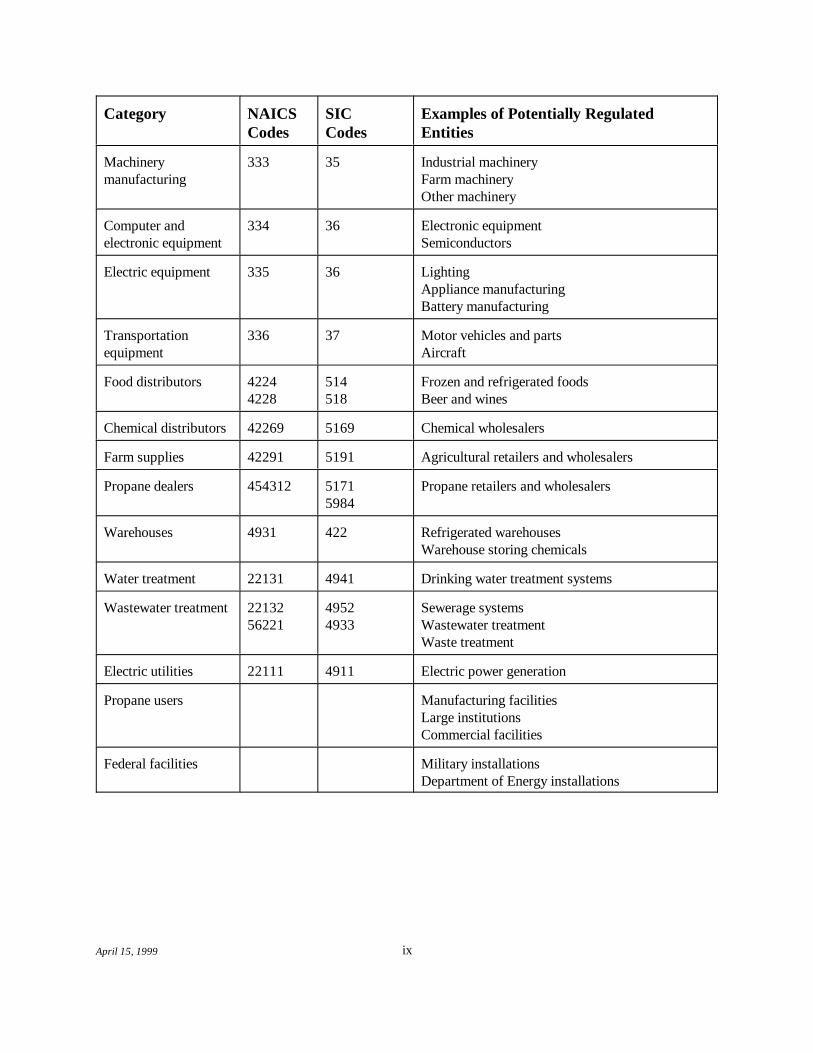
TABLE OF POTENTIALLY REGULATED ENTITIES
This table is not intended to be exhaustive, but rather provides a guide forreaders regarding entities likely to be regulated under 40 CFR part 68. Thistable lists the types of entities that EPA is now aware could potentially beregulated by this rule (see Appendix B of the “General Guidance for RiskManagement Programs” for a more detailed list of potentially affected NAICScodes). Other types of entities not listed in this table could also be affected. Todetermine whether your facility is covered by the risk management program rulesin part 68, you should carefully examine the applicability criteria discussed inChapter 1 of the General Guidance and in 40 CFR 68.10. If you have questionsregarding the applicability of this rule to a particular entity, call theEPCRA/CAA Hotline at (800) 424-9346 (TDD: (800) 553-7672).
Category NAICS SIC Examples of Potentially RegulatedCodes Codes Entities
Chemical 325 28 Petrochemicalsmanufacturers Industrial gas
Alkalies and chlorineIndustrial inorganicsIndustrial organicsPlastics and resinsAgricultural chemicalsSoap, cleaning compoundsExplosivesMiscellaneous chemical manufacturing
Petroleum refineries 32411 2911 Petroleum refineries
Pulp and paper 322 26 Paper millsPulp millsPaper products
Food processors 311 20 Dairy productsFruits and vegetablesMeat productsSeafood products
Polyurethane foam 32615 3086 Plastic foam products
Non-metallic mineral 327 32 Glass and glass productsproducts Other non-metallic mineral products
Metal products 331 33 Primary metal manufacturing 332 34 Fabricated metal products
Category NAICS SIC Examples of Potentially RegulatedCodes Codes Entities
ixApril 15, 1999
Machinery 333 35 Industrial machinerymanufacturing Farm machinery
Other machinery
Computer and 334 36 Electronic equipmentelectronic equipment Semiconductors
Electric equipment 335 36 LightingAppliance manufacturingBattery manufacturing
Transportation 336 37 Motor vehicles and partsequipment Aircraft
Food distributors 4224 514 Frozen and refrigerated foods4228 518 Beer and wines
Chemical distributors 42269 5169 Chemical wholesalers
Farm supplies 42291 5191 Agricultural retailers and wholesalers
Propane dealers 454312 5171 Propane retailers and wholesalers5984
Warehouses 4931 422 Refrigerated warehousesWarehouse storing chemicals
Water treatment 22131 4941 Drinking water treatment systems
Wastewater treatment 22132 4952 Sewerage systems56221 4933 Wastewater treatment
Waste treatment
Electric utilities 22111 4911 Electric power generation
Propane users Manufacturing facilitiesLarge institutions Commercial facilities
Federal facilities Military installationsDepartment of Energy installations

xApril 15, 1999
Roadmap to Offsite Consequence Analysis Guidance by Type of Chemical
Type of Chemical and Release Scenario Applicable Sections and Appendices
Toxic Gas
Worst-Case Scenario
1) Define Worst Case Section 2.12) Select Scenario Sections 2.2 and 2.33) Calculate Release Rates
Unmitigated Section 3.1.1Passive Mitigation Section 3.1.2Refrigerated Section 3.1.3
4) Find Toxic Endpoint Appendix B (Exhibit B-1)5) Determine Reference Table and Distance Section 3.1.3, 3.2.3
Dense or Neutrally Buoyant Plume Chapter 4 and Appendix B (Exhibit B-1)Chemical-Specific Tables (ammonia, chlorine, sulfur dioxide) Chapter 4Urban or Rural Section 2.1 and Chapter 4Release Duration Section 2.1
Alternative Scenario
1) Define Alternative Scenario Chapter 62) Select Scenario Chapter 63) Calculate Release Rates
Unmitigated (from tanks and pipes) Section 7.1.1Active or Passive Mitigation Section 7.1.2
4) Find Toxic Endpoint Appendix B (Exhibit B-1)5) Determine Reference Table and Distance
Dense or Neutrally Buoyant Plume Chapter 8 and Appendix B (Exhibit B-1)Chemical-Specific Tables (ammonia, chlorine, sulfur dioxide) Chapter 8Urban or Rural Section 2.1 and Chapter 8Release Duration Section 7.1

Roadmap to Offsite Consequence Analysis Guidance by Type of Chemical (continued)
Type of Chemical and Release Scenario Applicable Sections and Appendices
xiApril 15, 1999
Toxic Liquid
Worst-Case Scenario
1) Define Worst Case Section 2.12) Select Scenario Sections 2.2 and 2.33) Calculate Release Rates
Releases from Pipes Section 3.2.1Unmitigated Pool Evaporation Section 3.2.2Passive Mitigation (dikes, buildings) Section 3.2.3Release at Ambient Temperature Section 3.2.2, 3.2.3Release at Elevated Temperature Section 3.2.2, 3.2.3Releases of Mixtures Section 3.2.4 and Appendix B (Section B.2)Temperature Corrections for Liquids at 25-50 C Section 3.2.5 and Appendix B (Exhibit B-4)o
Releases of Solutions Section 3.3 and Appendix B (Exhibit B-3)4) Find Toxic Endpoint
For Liquids/Mixtures Appendix B (Exhibit B-2)For Solutions Appendix B (Exhibit B-3)
5) Determine Reference Table and DistanceDense or Neutrally Buoyant Plume (liquids) Chapter 4 and Appendix B (Exhibit B-2)Dense or Neutrally Buoyant Plume (solutions) Chapter 4 and Appendix B (Exhibit B-3)Chemical Specific Table (aqueous ammonia) Chapter 4Urban or Rural Section 2.1 and Chapter 4Release Duration (liquids) Section 3.2.2Release Duration (solutions) Chapter 4

Roadmap to Offsite Consequence Analysis Guidance by Type of Chemical (continued)
Type of Chemical and Release Scenario Applicable Sections and Appendices
xiiApril 15, 1999
Toxic Liquid
Alternative Scenario
1) Define Alternative Scenario Chapter 62) Select Scenario Chapter 63) Calculate Release Rates Section 7.2
Unmitigated (from tanks and pipes) Section 7.2.1Active or Passive Mitigation Section 7.2.2Release at Ambient Temperature Section 7.2.3Release at Elevated Temperature Section 7.2.3Release of Solution Sections 7.2.4 and 3.3 and Appendix B (Exhibit B-3)
4) Find Toxic EndpointFor Liquids/Mixtures Appendix B (Exhibit B-2)For Solutions Appendix B (Exhibit B-3)
5) Determine Reference Table and DistanceDense or Neutrally Buoyant Plume (liquids/mixtures) Chapter 8 and Appendix B (Exhibit B-2)Dense or Neutrally Buoyant Plume (solutions) Chapter 8 and Appendix B (Exhibit B-3)Chemical-Specific Table (aqueous ammonia) Chapter 8Urban or Rural Section 2.1 and Chapter 8Release Duration (liquids/mixtures) Section 7.2Release Duration (solutions) Chapter 8

Roadmap to Offsite Consequence Analysis Guidance by Type of Chemical (continued)
Type of Chemical and Release Scenario Applicable Sections and Appendices
xiiiApril 15, 1999
Flammable Substance
Worst-Case Scenario
1) Define Worst Case Sections 5.1 and 2.12) Select Scenario Sections 5.1, 2.2, and 2.33) Determine Distance to Overpressure Endpoint
For Pure Flammable Substances Section 5.1For Flammable Mixtures Section 5.2
Alternative Scenario
1) Define Alternative Scenario Chapter 62) Select Scenario Chapter 63) For Vapor Cloud Fires
Calculate Release Rates (gases) Section 9.1 and Appendix C (Exhibit C-2)Calculate Release Rates (liquids) Section 9.2 and Appendix C (Exhibit C-3)Find Lower Flammability Limit (gases) Appendix C (Exhibit C-2)Find Lower Flammability Limit (liquids) Appendix C (Exhibit C-3)Dense or Neutrally Buoyant (gases) Appendix C (Exhibit C-2)Dense or Neutrally Buoyant (liquids) Appendix C (Exhibit C-3)Urban or Rural Section 10.1Release Duration Section 10.1Determine Distance Section 10.1
4) For Pool Fires Section 10.2 and Appendix C (Exhibit C-3)5) For BLEVEs Section 10.36) For Vapor Cloud Explosions Section 10.4

xivApril 15, 1999
This page intentionally left blank.

April 15, 1999
1 INTRODUCTION
1.1 Purpose of this Guidance
This document provides guidance on how to conduct the offsite consequence analyses for RiskManagement Programs required under the Clean Air Act (CAA). Section 112(r)(7) of the CAA directed theU. S. Environmental Protection Agency (EPA) to issue regulations requiring facilities with large quantities ofvery hazardous chemicals to prepare and implement programs to prevent the accidental release of thosechemicals and to mitigate the consequences of any releases that do occur. EPA issued that rule,“ChemicalAccident Prevention Provisions” on June 20, 1996. The rule is codified at part 68 of Title 40 of the Code ofFederal Regulations (CFR). If you handle, manufacture, use, or store any of the toxic or flammablesubstances listed in 40 CFR 68.130 above the specified threshold quantities in a process, you are required todevelop and implement a risk management program under part 68 of 40 CFR. The rule applies to a widevariety of facilities that handle, manufacture, store, or use toxic substances, including chlorine and ammonia,and highly flammable substances, such as propane. If you are not sure whether you are subject to the rule,you should review the rule and Chapters 1 and 2 of EPA’s General Guidance for Risk ManagementPrograms (40 CFR part 68), available from EPA at http://www.epa.gov/ceppo/.
If you are subject to the rule, you are required to conduct an offsite consequence analysis to provideinformation to the state, local, and federal governments and the public about the potential consequences of anaccidental chemical release. The offsite consequence analysis consists of two elements:
z A worst-case release scenario, and
z Alternative release scenarios.
To simplify the analysis and ensure comparability, EPA has defined the worst-case scenario as therelease of the largest quantity of a regulated substance from a single vessel or process line failure that resultsin the greatest distance to an endpoint. In broad terms, the distance to the endpoint is the distance a toxicvapor cloud, heat from a fire, or blast waves from an explosion will travel before dissipating to the point thatserious injuries from short-term exposures will no longer occur. Endpoints for regulated substances arespecified in 40 CFR 68.22(a) and Appendix A of part 68 and are presented in Appendices B and C of thisguidance.
Alternative release scenarios are scenarios that are more likely to occur than the worst-case scenarioand that will reach an endpoint offsite, unless no such scenario exists. Within these two parameters, youhave flexibility to choose alternative release scenarios that are appropriate for your site. The rule, in 40 CFR68.28 (b)(2), and the General Guidance for Risk Management Programs (40 CFR part 68), Chapter 4,provide examples of alternative release scenarios that you should consider when conducting the offsiteconsequence analysis.

Chapter 1Introduction
1 - 2April 15, 1999
RMP*Comp™
To assist those using this guidance, the National Oceanic and Atmospheric Administration (NOAA) andEPA have developed a software program, RMP*Comp™, that performs the calculations described inthis document. This software can be downloaded from the EPA/CEPPO Internet website athttp://www.epa.gov/ceppo/ds-epds.htm#comp.
This guidance document provides a simple methodology for conducting offsite consequence analyses. You may use simple equations to estimate release rates and reference tables to determine distances to theendpoint of concern. This guidance provides generic reference tables of distances, applicable to most of theregulated toxic substances, and chemical-specific tables for ammonia, chlorine, and sulfur dioxide. Thisguidance also provides reference tables of distances for consequences of fires and explosions of flammablesubstances. In some cases, the rule allows users of this document to adopt generic assumptions rather than thesite-specific data required if another model is employed (see Exhibit 1).
The methodology and reference tables of distances presented here are optional. You are notrequired to use this guidance. You may use publicly available or proprietary air dispersion models to doyour offsite consequence analysis, subject to certain conditions. If you choose to use models instead of thisguidance, you should review the rule and Chapter 4 of the General Guidance for Risk ManagementPrograms, which outline required conditions for use of models. In selected example analyses, this documentpresents the results of some models to provide a basis for comparison. It also indicates certain conditions of arelease that may warrant more sophisticated modeling than is represented here. However, this guidance doesnot discuss the procedures to follow when using models; if you choose to use models, you should consult theappropriate references or instructions for those models.
This guidance provides distances to endpoints for toxic substances that range from 0.1 miles to 25miles. Other models may not project distances this far (and some may project even longer distances). Onecommonly used model, ALOHA, has an artificial distance cutoff of 6 miles (i.e., any scenario which wouldresult in an endpoint distance beyond 6 miles is reported as “greater than 6 miles”). Although you may useALOHA if it is appropriate for the substance and scenario, you should consider choosing a different model ifthe scenario would normally result in an endpoint distance significantly greater than 6 miles. Otherwise, youshould be prepared to explain the difference between your results and those in this guidance or othercommonly used models. Also, you should be aware that the RMP*Submit system accepts only numericalentries (i.e., it will not accept a “greater than” distance). If you do enter a distance in RMP*Submit that is theresult of a particular model’s maximum distance cutoff (including the maximum distance cutoff in thisguidance), you can explain this in the executive summary of your RMP.

1 - 3April 15, 1999
Exhibit 1Required Parameters for Modeling (40 CFR 68.22)
WORST CASE ALTERNATIVE SCENARIO
Endpoints (§68.22(a))
Endpoints for toxic substances are specified in part 68 Appendix A. Endpoints for toxic substances are specified in part 68 Appendix A.
For flammable substances, endpoint is overpressure of 1 pound per square For flammable substances, endpoint is:inch (psi) for vapor cloud explosions. JOverpressure of 1 psi for vapor cloud explosions, or
JRadiant heat level of 5 kilowatts per square meter (kW/m ) for 402
seconds for heat from fires (or equivalent dose), or JLower flammability limit (LFL) as specified in NFPA documents orother generally recognized sources.
Wind speed/stability (§68.22(b))
This guidance assumes 1.5 meters per second and F stability. For other This guidance assumes wind speed of 3 meters per second and Dmodels, use wind speed of 1.5 meters per second and F stability class stability. For other models, you must use typical meteorologicalunless you can demonstrate that local meteorological data applicable to conditions for your site. the site show a higher minimum wind speed or less stable atmosphere atall times during the previous three years. If you can so demonstrate, theseminimums may be used for site-specific modeling.
Ambient temperature/humidity (§68.22(c))
This guidance assumes 25(C (77(F) and 50 percent humidity. For other This guidance assumes 25(C and 50 percent humidity. For othermodels for toxic substances, you must use the highest daily maximum models, you may use average temperature/humidity data gathered at thetemperature and average humidity for the site during the past three years. site or at a local meteorological station.
Height of release (§68.22(d))
For toxic substances, you must assume a ground level release. This guidance assumes a ground-level release. For other models, releaseheight may be determined by the release scenario.
Surface roughness (§68.22(e))
Use urban (obstructed terrain) or rural (flat terrain) topography, as Use urban (obstructed terrain) or rural (flat terrain) topography, asappropriate. appropriate.
Dense or neutrally buoyant gases (§68.22(f))
Tables or models used for dispersion of regulated toxic substances must Tables or models used for dispersion must appropriately account for gasappropriately account for gas density. If you use this guidance, see Tables density. If you use this guidance, see Tables 14-17 for neutrally1-4 for neutrally buoyant gases and Tables 5-8 for dense gases, or Tables buoyant gases and Tables 18-21 for dense gases, or Tables 22-25 for9-12 for specific chemicals. specific chemicals.
Temperature of released substance (§68.22(g))
You must consider liquids (other than gases liquefied by refrigeration) to Substances may be considered to be released at a process or ambientbe released at the highest daily maximum temperature, from data for the temperature that is appropriate for the scenario. This guidanceprevious three years, or at process temperature, whichever is higher. provides factors for estimation of release rates at 25(C or the boilingAssume gases liquefied by refrigeration at atmospheric pressure to be point of the released substance, and also provides temperaturereleased at their boiling points. This guidance provides factors for correction factors. estimation of release rates at 25(C or the boiling point of the releasedsubstance, and also provides temperature correction factors.

Chapter 1Introduction
1 - 4April 15, 1999
1.2 This Guidance Compared to Other Models
Results obtained using the methods in this document are expected to be conservative (i.e., they willgenerally, but not always, overestimate the distance to endpoints). The chemical-specific reference tables inthis guidance provide less conservative results than the generic reference tables, because the chemical-specifictables were derived using more realistic assumptions and considering more factors.
Complex models that can account for many site-specific factors may give less conservative estimatesof offsite consequences than the simple methods in this guidance. This is particularly true for alternativescenarios, for which EPA has not specified many assumptions. However, complex models may be expensiveand require considerable expertise to use; this guidance is designed to be simple and straightforward. Youwill need to consider these tradeoffs in deciding how to carry out your required consequence analyses. Appendix A provides information on references for some other methods of analysis; these references do notinclude all models that you may use for these analyses. You will find that modeling results will sometimesvary considerably from model to model.
1.3 Number of Scenarios to Analyze
The number and type of analyses you must perform depend on the “Program” level of each of yourprocesses. The rule defines three Program levels. Processes are eligible for Program 1 if, among othercriteria, there are no public receptors within the distance to the endpoint for the worst-case scenario. Becauseno public receptors would be affected by the worst-case release, no further modeling is required for theseprocesses. For processes subject to Program 2 or Program 3, both worst-case release scenarios andalternative release scenarios are required. To determine the Program level of your processes, consult 40 CFR68.10(b), (c), and (d), or Chapter 2 of EPA’s General Guidance for Risk Management Programs (40 CFRpart 68).
Once you have determined the Program level of your processes, you are required to conduct thefollowing offsite consequence analyses:
& One worst-case release scenario for each Program 1 process;
& One worst-case release scenario to represent all regulated toxic substances in Program 2 andProgram 3 processes;
& One worst-case release scenario to represent all regulated flammable substances in Program2 and Program 3 processes;
& One alternative release scenario for each regulated toxic substance in Program 2 andProgram 3 processes; and
& One alternative release scenario to represent all regulated flammable substances in Program2 and Program 3 processes.
NOTE: You may need to analyze additional worst-case scenarios if release scenarios for regulatedflammable or toxic substances from other covered processes at your facility would affect different public

Chapter 1Introduction
1 - 5April 15, 1999
GUIDANCE FOR INDUSTRY-SPECIFIC RISK MANAGEMENT PROGRAMS
EPA developed guidance for industry-specific risk management programs for the following industries:
J Propane storage facilities J WarehousesJ Chemical distributors J Ammonia refrigerationJ Waste water treatment plants J Small propane retailers & users
The industry-specific guidances are available from EPA at http://www.epa.gov/ceppo/.
Industry-specific guidances developed by EPA take the place of this guidance document and the GeneralGuidance for Risk Management Programs for the industries addressed. If an industry-specific programexists for your process(es), you should use it as your basic guidance because it will provide moreinformation that is specific to your process, including dispersion modeling.
receptors. For example, worst-case release scenarios for storage tanks at opposite ends of your facility maypotentially reach different areas where people could be affected. In that case, you will have to conductanalyses of and report on both releases.
1.4 Modeling Issues
The consequences of an accidental chemical release depend on the conditions of the release and theconditions at the site at the time of the release. This guidance provides reference tables of distances, based onresults of modeling, for estimation of worst-case and alternative scenario consequence distances. Worst-caseconsequence distances obtained using these tables are not intended to be precise predictions of the exactdistances that might be reached in the event of an actual accidental release. For this guidance, worst-casedistances are based on modeling results assuming the combination of worst-case conditions required by therule. This combination of conditions occurs rarely and is unlikely to persist for very long. To derive thealternative scenario distances, less conservative assumptions were used for modeling; these assumptions werechosen to represent more likely conditions than the worst-case assumptions. Nevertheless, in an actualaccidental release, the conditions may be very different. Users of this guidance should remember that theresults derived from the methods presented here are rough estimates of potential consequence distances. Other models may give different results; the same model also may give different results if differentassumptions about release conditions and/or site conditions are used.
The reference tables of distances in this guidance provide results to a maximum distance of 25 miles. EPA recognizes that modeling results at such large distances are highly uncertain. Almost no experimentaldata or data from accidents are available at such large distances to compare to modeling results. Most dataare reported for distances well under 10 miles. Modeling uncertainties are likely to increase as distancesincrease because conditions (e.g., atmospheric stability, wind speed, surface roughness) are not likely toremain constant over large distances. Thus, at large distances (e.g., greater than about 6 to 10 miles), themodeling results should be viewed as very coarse estimates of consequence distances. EPA believes,

Chapter 1Introduction
1 - 6April 15, 1999
however, that the results, even at large distances, can provide useful information for comparison purposes. For example, Local Emergency Planning Committees (LEPCs) and other local agencies can use relativedifferences in distance to aid in establishing chemical accident prevention and preparedness priorities amongfacilities in a community. Since worst-case scenario distances are based on modeling conditions that areunlikely to occur, and since modeling of any scenario that results in large distances is very uncertain, EPAstrongly urges communities and industry not to rely on the results of worst-case modeling or any modelingthat results in very large toxic endpoint distances in emergency planning and response activities. Results ofalternative scenario models are apt to provide a more reasonable basis for planning and response.
1.5 Steps for Performing the Analysis
This Chapter presents the steps you should follow in using this guidance to carry out an offsiteconsequence analysis. Before carrying out one or more worst-case and/or alternative release analyses, youwill need to obtain several pieces of information about the regulated substances you have, the areasurrounding your site, and typical meteorological conditions:
& Determine whether each regulated substance is toxic or flammable, as indicated in the rule orAppendices B and C of this guidance.
& For the worst-case analysis, determine the quantity of each substance held in the largestsingle vessel or pipe.
& Collect information about any passive or active (alternative scenarios only) releasemitigation measures that are in place for each substance.
& For toxic substances, determine whether the substance is stored as a gas, as a liquid, as a gasliquefied by refrigeration, or as a gas liquefied under pressure. For alternative scenariosinvolving a vapor cloud fire, you may also need this information for flammable substances.
& For toxic liquids, determine the highest daily maximum temperature of the liquid, based ondata for the previous three years, or process temperature, whichever is higher.
& For toxic substances, determine whether the substance behaves as a dense or neutrallybuoyant gas or vapor (see Appendix B, Exhibits B-1 and B-2). For alternative scenariosinvolving a vapor cloud fire, you will also need this information for flammable substances(see Appendix C, Exhibits C-2 and C-3).
& For toxic substances, determine whether the topography (surface roughness) of your site iseither urban or rural as thse terms are defined by the rule (see 40 CFR 68.22(e)). Foralternative scenarios involving a vapor cloud fire, you will also need this information forflammable substances.
After you have gathered the above information, you will need to take three steps (except forflammable worst-case releases):
(1) Select a scenario;

Chapter 1Introduction
1 - 7April 15, 1999
(2) Determine the release or volatilization rate; and(3) Determine the distance to the endpoint.
For flammable worst-case scenarios, only steps one and three are needed. Sections 1.5.1 through 1.5.6outline the procedures to perform the analyses. In addition to basic procedures, these sections providereferences to sections of this guidance where you will find detailed instructions on carrying out the applicableportion of the analysis. Sections 1.5.1 through 1.5.3 below provide basic steps to analyze worst-casescenarios for toxic gases, toxic liquids, and flammable substances. Sections 1.5.4 through 1.5.6 providebasic steps for alternative scenario analysis. Appendix E of this document provides worksheets that may helpyou to perform the analyses.
1.5.1 Worst-Case Analysis for Toxic Gases
To conduct worst-case analyses for toxic gases, including toxic gases liquefied by pressurization (seeAppendix E, Worksheet 1, for a worksheet that can be used in carrying out this analysis):
Step 1: Determine worst-case scenario. Identify the toxic gas, quantity, and worst-case release scenario, asdefined by the rule (Chapter 2).
Step 2: Determine release rate. Estimate the release rate for the toxic gas, using the parameters required bythe rule. This guidance provides methods for estimating the release rate for:
& Unmitigated releases (Section 3.1.1).
& Releases with passive mitigation (Section 3.1.2).
Step 3: Determine distance to endpoint. Estimate the worst-case consequence distance based on the releaserate and toxic endpoint (defined by the rule) (Chapter 4). This guidance provides reference tables ofdistances (Reference Tables 1-12). Select the appropriate reference table based on the density of thereleased substance, the topography of your site, and the duration of the release (always 10 minutesfor gas releases). Estimate distance to the endpoint from the appropriate table.
1.5.2 Worst-Case Analysis for Toxic Liquids
To conduct worst-case analyses for toxic substances that are liquids at ambient conditions or fortoxic gases that are liquefied by refrigeration alone (see Appendix E, Worksheet 2, for a worksheet for thisanalysis):
Step 1: Determine worst-case scenario. Identify the toxic liquid, quantity, and worst-case release scenario, asdefined by the rule (Chapter 2). To estimate the quantity of liquid released from piping, see Section3.2.1.
Step 2: Determine release rate. Estimate the volatilization rate for the toxic liquid and the duration of therelease, using the parameters required by the rule. This guidance provides methods for estimating thepool evaporation rate for:

Chapter 1Introduction
1 - 8April 15, 1999
& Gases liquefied by refrigeration alone (Sections 3.1.3 and 3.2.3).
& Unmitigated releases (Section 3.2.2).
& Releases with passive mitigation (Section 3.2.3).
& Releases at ambient or elevated temperature (Sections 3.2.2, 3.2.3, and 3.2.5).
& Releases of mixtures of toxic liquids (Section 3.2.4).
& Releases of common water solutions of regulated substances and of oleum (Section 3.3).
Step 3: Determine distance to endpoint. Estimate the worst-case consequence distance based on the releaserate and toxic endpoint (defined by the rule) (Chapter 4). This guidance provides reference tables ofdistances (Reference Tables 1-12). Select the appropriate reference table based on the density of thereleased substance, the topography of your site, and the duration of the release. Estimate distance tothe endpoint from the appropriate table.
1.5.3 Worst-Case Analysis for Flammable Substances
To conduct worst-case analyses for all regulated flammable substances (i.e., gases and liquids) (seeAppendix E, Worksheet 3, for a worksheet for this analysis):
Step 1: Determine worst-case scenario. Identify the appropriate flammable substance, quantity, and worst-case scenario, as defined by the rule (Chapter 2).
Step 2: Determine distance to endpoint. Estimate the distance to the required overpressure endpoint of 1 psifor a vapor cloud explosion of the flammable substance, using the assumptions required by the rule(Chapter 5). This guidance provides a reference table of distances (Reference Table 13) for worst-case vapor cloud explosions. Estimate the distance to the endpoint from the quantity released and thetable.
1.5.4 Alternative Scenario Analysis for Toxic Gases
To conduct alternative release scenario analyses for toxic gases, including toxic gases liquefied bypressurization (see Appendix E, Worksheet 4, for a worksheet for this analysis):
Step 1: Select alternative scenario. Choose an appropriate alternative release scenario for the toxic gas. Thisscenario should have the potential for offsite impacts unless no such scenario exists. (Chapter 6).
Step 2: Determine release rate. Estimate the release rate and duration of the release of the toxic gas, basedon your scenario and site-specific conditions. This guidance provides methods for:
& Unmitigated releases (Section 7.1.1).
& Releases with active or passive mitigation (Section 7.1.2).

Chapter 1Introduction
1 - 9April 15, 1999
Step 3: Determine distance to endpoint. Estimate the alternative scenario distance based on the release rateand toxic endpoint (Chapter 8). This guidance provides reference tables of distances (ReferenceTables 14-25) for alternative scenarios for toxic substances. Select the appropriate reference tablebased on the density of the released substance, the topography of your site, and the duration of therelease. Estimate distance to the endpoint from the appropriate table.
1.5.5 Alternative Scenario Analysis for Toxic Liquids
To conduct alternative release scenario analyses for toxic substances that are liquids at ambientconditions or for toxic gases that are liquefied by refrigeration alone (see Appendix E, Worksheet 5, for aworksheet for this analysis):
Step 1: Select alternative scenario. Choose an appropriate alternative release scenario and release quantityfor the toxic liquid. This scenario should have the potential for offsite impacts (Chapter 6), unless nosuch scenario exists.
Step 2: Determine release rate. Estimate the release rate and duration of the release of the toxic liquid, basedon your scenario and site-specific conditions. This guidance provides methods to estimate the liquidrelease rate and quantity of liquid released for:
& Unmitigated liquid releases (Section 7.2.1).
& Mitigated liquid releases (Section 7.2.2).
The released liquid is assumed to form a pool. This guidance provides methods to estimate the poolevaporation rate and release duration for:
& Unmitigated releases (Section 7.2.3).
& Releases with passive or active mitigation (Section 7.2.3).
& Releases at ambient or elevated temperature (Sections 7.2.3).
& Releases of common water solutions of regulated substances and of oleum (Section 7.2.4).
Step 3: Determine distance to endpoint. Estimate the alternative scenario distance based on the release rateand toxic endpoint (Chapter 8). This guidance provides reference tables of distances (ReferenceTables 14-25) for alternative scenarios for toxic substances. Select the appropriate reference tablebased on the density of the released substance, the topography of your site, and the duration of therelease. Estimate distance to the endpoint from the appropriate table.
1.5.6 Alternative Scenario Analysis for Flammable Substances
To conduct alternative release scenario analyses for all regulated flammable substances (i.e., gasesand liquids) (see Appendix E, Worksheet 6, for a worksheet for this analysis):

Chapter 1Introduction
1 - 10April 15, 1999
Step 1: Select alternative scenario. Identify the flammable substance, and choose the quantity and type ofevent for the alternative scenario consequence analysis (Chapter 6).
Step 2: Determine release rate. Estimate the release rate to air of the flammable gas or liquid, if the scenarioinvolves a vapor cloud fire (Section 9.1 for flammable gases, Section 9.2 for flammable liquids).
Step 3: Determine distance to endpoint. Estimate the distance to the appropriate endpoint (defined by therule). This guidance provides methods for:
& Vapor cloud fires (Section 10.1 and Reference Tables 26-29); select the appropriatereference table based on the density of the released substance and the topography of yoursite, and estimate distance to the endpoint from the appropriate table.
& Pool fires (Section 10.2); estimate distance from the equation and chemical-specific factorsprovided.
& BLEVEs (Section 10.3 and Reference Table 30); estimate distance from the quantity offlammable substance and the table.
& Vapor cloud explosions (Section 10.4 and Reference Table 13); estimate quantity in thecloud from the equation and chemical-specific factors provided, and estimate distance fromthe quantity, the table, and a factor provided for alternative scenarios.
1.6 Additional Sources of Information
EPA’s risk management program requirements may be found at 40 CFR part 68. The relevantsections were published in the Federal Register on January 31, 1994 (59 FR 4478) and June 20, 1996 (61FR 31667). Final rules amending the list of substances and thresholds were published on August 25, 1997(62 FR 45130) and January 6, 1998 (63 FR 640). A consolidated copy of these regulations is available inAppendix F.
EPA is working with industry and local, state, and federal government agencies to assist sources incomplying with these requirements. For more information, refer to the General Guidance for RiskManagement Programs Appendix E (Technical Assistance). Appendices C and D of the General Guidancealso provide points of contact for EPA and Occupational Safety and Health Administration (OSHA) at thestate and federal levels for your questions. Your LEPC also can be a valuable resource.
Finally, if you have access to the Internet, EPA has made copies of the rules, fact sheets, and otherrelated materials available at the home page of EPA's Chemical Emergency Preparedness and PreventionOffice (http://www.epa.gov/ceppo/). Please check the site regularly, as additional materials are posted whenthey become available. If you do not have access to the Internet, you can call EPA’s hotline at (800) 424-9346.

April 15, 1999
In Chapter 2
& 2.1 EPA’s definition of a worst-case scenario.
& 2.2 How to determine the quantity released.
& 2.3 How to identify the appropriate worst-case scenario.
2 DETERMINING WORST-CASE SCENARIOS
2.1 Definition of Worst-Case Scenario
A worst-case release is defined as:
& The release of the largest quantity of a regulated substance from a vessel or process linefailure, and
& The release that results in the greatest distance to the endpoint for the regulated toxic orflammable substance.
You may take administrative controls into account when determining the largest quantity.Administrative controls are written procedures that limit the quantity of a substance that can be stored orprocessed in a vessel or pipe at any one time or, alternatively, procedures that allow the vessel or pipe tooccasionally store larger than usual quantities (e.g., during shutdown or turnaround). Endpoints for regulatedsubstances are specified in the rule (40 CFR 68.22(a), and Appendix A to part 68 for toxic substances). Forthe worst-case analysis, you do not need to consider the possible causes of the worst-case release or theprobability that such a release might occur; the release is simply assumed to take place. You must assume allreleases take place at ground level for the worst-case analysis.
This guidance assumes meteorological conditions for the worst-case scenario of atmospheric stabilityclass F (stable atmosphere) and wind speed 1.5 meters per second (3.4 miles per hour). Ambient airtemperature for this guidance is 25 C (77 F). If you use this guidance, you may assume this ambient o o
temperature for the worst case, even if the maximum temperature at your site in the last three years is higher.
The rule provides two choices for topography, urban and rural. EPA (40 CFR 68.22(e)) has definedurban as many obstacles in the immediate area, where obstacles include buildings or trees. Rural, by EPA’sdefinition, means there are no buildings in the immediate area, and the terrain is generally flat andunobstructed. Thus, if your site is located in an area with few buildings or other obstructions (e.g., hills,trees), you should assume open (rural) conditions. If your site is in an area with many obstructions, even if itis in a remote location that would not usually be considered urban, you should assume urban conditions.
Toxic Gases
Toxic gases include all regulated toxic substances that are gases at ambient temperature (25 C, 77o
F), with the exception of gases liquefied by refrigeration under atmospheric pressure and released into dikedo
areas. For the worst-case consequence analysis, you must assume that a gaseous release of the total quantityoccurs in 10 minutes. You may take passive mitigation measures (e.g., enclosure) into account in the analysisof the worst-case scenario.

Chapter 2Determining Worst-Case Scenarios
2 - 2April 15, 1999
Gases liquefied by refrigeration alone and released into diked areas may be modeled as liquids attheir boiling points and assumed to be released from a pool by evaporation (40 CFR 68.25(c)(2)). Gasesliquefied by refrigeration alone that would form a pool one centimeter or less in depth upon release must bemodeled as gases. (Modeling indicates that pools one centimeter or less deep formed by gases liquefied byrefrigeration would completely evaporate in 10 minutes or less, giving a release rate that is equal to or greaterthan the worst-case release rate for a gaseous release. In this case, therefore, it is appropriate to treat thesesubstances as gases for the worst-case analysis.)
Endpoints for consequence analysis for regulated toxic substances are specified in the rule (40 CFRpart 68, Appendix A). Exhibit B-1 of Appendix B lists the endpoint for each toxic gas. These endpoints areused for air dispersion modeling to estimate the consequence distance.
Toxic Liquids
For toxic liquids, you must assume that the total quantity in a vessel is spilled. This guidanceassumes the spill takes place onto a flat, non-absorbing surface. For toxic liquids carried in pipelines, thequantity that might be released from the pipeline is assumed to form a pool. You may take passive mitigationsystems (e.g., dikes) into account in consequence analysis. The total quantity spilled is assumed to spreadinstantaneously to a depth of one centimeter (0.033 foot or 0.39 inch) in an undiked area or to cover a dikedarea instantaneously. The temperature of the released liquid must be the highest daily maximum temperatureoccurring in the past three years or the temperature of the substance in the vessel, whichever is higher (40CFR 68.25(d)(2)). The release rate to air is estimated as the rate of evaporation from the pool. If liquids atyour site might be spilled onto a surface that could rapidly absorb the spilled liquid (e.g., porous soil), themethods presented in this guidance may greatly overestimate the consequences of a release. Consider usinganother method in such a case.
Exhibit B-2 of Appendix B presents the endpoint for air dispersion modeling for each regulated toxicliquid (the endpoints are specified in 40 CFR part 68, Appendix A).
Flammable Substances
For all regulated flammable substances, you must assume that the worst-case release results in avapor cloud containing the total quantity of the substance that could be released from a vessel or pipeline. For the worst-case consequence analysis, you must assume the vapor cloud detonates. If you use a TNT-equivalent method for your analysis, you must assume a 10 percent yield factor.
The rule specifies the endpoint for the consequence analysis of a vapor cloud explosion of a regulatedflammable substance as an overpressure of 1 pound per square inch (psi). This endpoint was chosen as thethreshold for potential serious injuries to people as a result of property damage caused by an explosion (e.g.,injuries from flying glass from shattered windows or falling debris from damaged houses). (See Appendix D,Section D.5 for additional information on this endpoint.)

Chapter 2Determining Worst-Case Scenarios
2 - 3April 15, 1999
Effect of Required Assumptions
The assumptions required for the worst-case analysis are intended to provide conservative worst-caseconsequence distances, rather than accurate predictions of the potential consequences of a release; that is, inmost cases your results will overestimate the effects of a release. In certain cases, actual conditions could beeven more severe than these worst-case assumptions (e.g., very high process temperature, high processpressure, or unusual weather conditions, such as temperature inversions); in such cases, your results mightunderestimate the effects. However, the required assumptions generally are expected to give conservativeresults.
2.2 Determination of Quantity for the Worst-Case Scenario
EPA has defined a worst-case release as the release of the largest quantity of a regulated substancefrom a vessel or process line failure that results in the greatest distance to a specified endpoint. Forsubstances in vessels, you must assume release of the largest amount in a single vessel. For substances inpipes, you must assume release of the largest amount in a pipe. The largest quantity should be determinedtaking into account administrative controls rather than absolute capacity of the vessel or pipe. Administrativecontrols are written procedures that limit the quantity of a substance that can be stored or processed in avessel or pipe at any one time, or, alternatively, occasionally allow a vessel or pipe to store larger than usualquantities (e.g., during turnaround).
2.3 Selecting Worst-Case Scenarios
Under part 68, a worst-case release scenario analysis must be completed for all covered processes,regardless of program level. The number of worst-case scenarios you must analyze depends on severalfactors. You need to consider only the hazard (toxicity or flammability) for which a substance is regulated(i.e., even if a regulated toxic substance is also flammable, you only need to consider toxicity in your analysis;even if a regulated flammable substance is also toxic, you only need to consider flammability).
For every Program 1 process, you must report the worst-case scenario with the greatest distance to anendpoint. If a Program 1 process has more than one regulated substance held above its threshold, you mustdetermine which substance produces the greatest distance to its endpoint and report on that substance. If aProgram 1 process has both regulated toxics and flammables above their thresholds, you still report only theone scenario that produces the greatest distance to the endpoint. The process is eligible for Program 1 if thereare no public receptors within the distance to an endpoint of the worst-case scenario for the process and theother Program 1 criteria are met. For Program 2 or Program 3 processes, you must analyze and report on oneworst-case analysis representing all toxic regulated substances present above the threshold quantity and oneworst-case analysis representing all flammable regulated substances present above the threshold quantity. You may need to submit an additional worst-case analysis if a worst-case release from elsewhere at the sourcewould potentially affect public receptors different from those affected by the initial worst-case scenario(s).
If you have more than one regulated substance in a class, the substance chosen for the consequenceanalysis for each hazard for Program 2 and 3 processes should be the substance that has the potential to causethe greatest offsite consequences. Choosing the toxic regulated substance that might lead to the greatestoffsite consequences may require a screening analysis of the toxic regulated substances on site, because thepotential consequences are dependent on a number of factors, including quantity, toxicity, and volatility.

Chapter 2Determining Worst-Case Scenarios
2 - 4April 15, 1999
Location (distance to the fenceline) and conditions of processing or storage (e.g., a high temperature process)also should be considered. In selecting the worst-case scenario, you may want to consider the followingpoints:
& Toxic gases with low toxic endpoints are likely to give the greatest distances to the endpointfor a given release quantity; a toxic gas would be a likely choice for the worst-case analysisrequired for Program 2 and 3 processes (processes containing toxic gases are unlikely to beeligible for Program 1).
& Volatile, highly toxic liquids (i.e., liquids with high ambient vapor pressure and low toxicendpoints) also are likely to give large distances to the endpoint (processes containing thistype of substance are unlikely to be eligible for Program 1).
& Toxic liquids with relatively low volatility (low vapor pressure) and low toxicity (large toxicendpoint) in ambient temperature processes may give fairly small distances to the endpoint;you probably would not choose such substances for the worst-case analysis for Program 2 or3 if you have other regulated toxics, but you may want to consider carrying out a worst-caseanalysis to demonstrate potential Program 1 eligibility.
For flammable substances, you must consider the consequences of a vapor cloud explosion in the
analysis. The severity of the consequences of a vapor cloud explosion depends on the quantity of the releasedsubstance in the vapor cloud, its heat of combustion, and other factors that are assumed to be the same for allflammable substances. In most cases, the analysis probably should be based on the regulated flammablesubstance present in the greatest quantity; however, a substance with a high heat of combustion may have agreater potential offsite impact than a larger quantity of a substance with a lower heat of combustion. Insome cases, a regulated flammable substance that is close to the fenceline might have a greater potentialoffsite impact than a larger quantity farther from the fenceline.
You are likely to estimate smaller worst-case distances for flammable substances than for similarquantities of most toxic substances. Because the distance to the endpoint may be relatively small, you mayfind it worthwhile to carry out a worst-case analysis for each process containing flammable substances todemonstrate potential eligibility for Program 1, unless there are public receptors close to the process.

April 15, 1999
In Chapter 3
& 3.1 Estimation of worst-case release rates for toxic gases.
& 3.2 Estimation of release rates for toxic liquids evaporating from pools.
& 3.3 Estimation of release rates for common water solutions of toxic substancesand for oleum.
In Section 3.1
& 3.1.1 Method to estimate worst-case release rates for unmitigated releases(releases directly to the air) of toxic gas.
& 3.1.2 Method to estimate worst-case release rates for toxic gas in enclosures(passive mitigation).
& 3.1.3 Method to estimate worst-case release rates for liquefied refrigeratedtoxic gases in diked areas (as toxic liquid - see Section 3.2.3), includingconsideration of the duration of the release.
3 RELEASE RATES FOR TOXIC SUBSTANCES
This chapter describes simple methods for estimating release rates for regulated toxic substances forthe worst-case scenario. Simple release rate equations are provided, and factors to be used in these equationsare provided (in Appendix B) for each regulated substance. The estimated release rates may be used toestimate dispersion distances to the toxic endpoint for regulated toxic gases and liquids, as discussed inChapter 4.
3.1 Release Rates for Toxic Gases
Regulated substances that are gases at ambient temperature (25 C, 77 F) should be consideredo o
gases for consequence analysis, with the exception of gases liquefied by refrigeration at atmospheric pressure. Gases liquefied under pressure should be treated as gases. Gases liquefied by refrigeration alone and releasedinto diked areas may be treated as liquids at their boiling points if they would form a pool upon release that ismore than one centimeter (0.033 foot) in depth. Gases liquefied by refrigeration alone that would form a poolone centimeter (0.033 foot) or less in depth should be treated as gases. Modeling shows that the evaporationrate from such a pool would be equal to or greater than the rate for a toxic gas, which is assumed to bereleased over 10 minutes; therefore, treating liquefied refrigerated gases as gases rather than liquids in suchcases is reasonable. You may consider passive mitigation for gaseous releases and releases of gases liquefiedby refrigeration.

QR
QS10
Chapter 3Release Rates for Toxic Substances
3 - 2April 15, 1999
(3-1)
Example 1. Gas Release (Diborane)
You have a tank containing 2,500 pounds of diborane gas. Assuming the total quantity in the tank is releasedover a 10-minute period, the release rate (QR), from Equation 3-1, is:
QR = 2,500 pounds/10 minutes = 250 pounds per minute
3.1.1 Unmitigated Releases of Toxic Gas
If no passive mitigation system is in place, estimate the release rate for the release over a 10-minuteperiod of the largest quantity resulting from a pipe or vessel failure, as required by the rule (40 CFR68.25(c)). For a release from a vessel, calculate the release rate as follows:
where: QR = Release rate (pounds per minute)QS = Quantity released (pounds)
3.1.2 Releases of Toxic Gas in Enclosed Space
If a gas is released in an enclosure such as a building or shed, the release rate to the outside air maybe lessened considerably. The dynamics of this type of release are complex; however, you may use thesimplified method presented here to estimate an approximate release rate to the outside air from a release inan enclosed space. The mitigation factor (i.e., 55 percent) presented in this method assumes that the releaseoccurs in a fully enclosed, non-airtight space that is directly adjacent to the outside air. If you are modeling arelease in an interior room that is enclosed within a building, a smaller factor (i.e., more mitigation) may beappropriate. On the other hand, a larger factor (i.e., less mitigation) should be used for a space that has doorsor windows that could be open during a release. If any of these special circumstances apply to your site, youmay want to consider performing site-specific modeling to determine the appropriate amount of passivemitigation. In addition, you should not incorporate the passive mitigation effect of building enclosures intoyour modeling if you have reason to believe the enclosure would not withstand the force of the release or ifthe chemical is handled outside the building (e.g., moved from one building to another building).
For the worst case, assume as before that the largest quantity resulting from a pipe or vessel failure isreleased over a 10-minute period. Determine the unmitigated worst-case scenario release rate of the gas asthe quantity released divided by 10 (Equation 3-1). The release rate from the building will be approximately55 percent of the worst-case scenario release rate (see Appendix D, Section D.1.2 for the derivation of thisfactor). Estimate the mitigated release rate as follows:
QR
QS10
× 0.55
Chapter 3Release Rates for Toxic Substances
3 - 3April 15, 1999
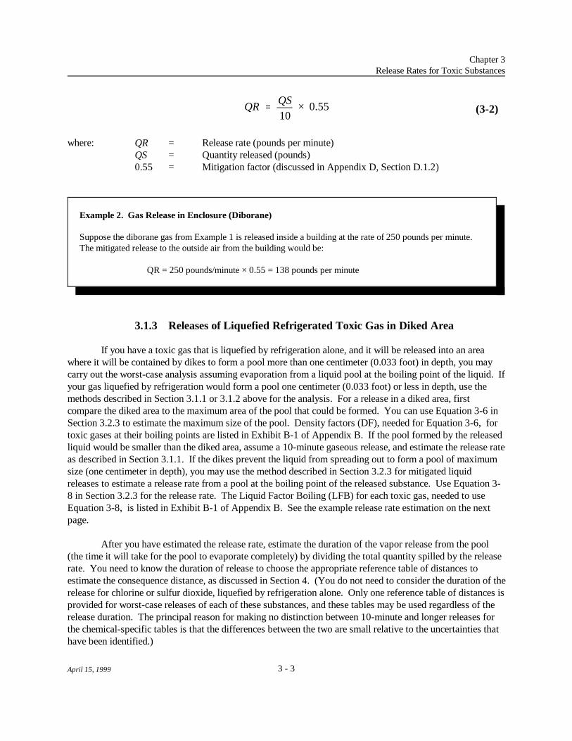
(3-2)
Example 2. Gas Release in Enclosure (Diborane)
Suppose the diborane gas from Example 1 is released inside a building at the rate of 250 pounds per minute. The mitigated release to the outside air from the building would be:
QR = 250 pounds/minute × 0.55 = 138 pounds per minute
where: QR = Release rate (pounds per minute)QS = Quantity released (pounds)0.55 = Mitigation factor (discussed in Appendix D, Section D.1.2)
3.1.3 Releases of Liquefied Refrigerated Toxic Gas in Diked Area
If you have a toxic gas that is liquefied by refrigeration alone, and it will be released into an areawhere it will be contained by dikes to form a pool more than one centimeter (0.033 foot) in depth, you maycarry out the worst-case analysis assuming evaporation from a liquid pool at the boiling point of the liquid. Ifyour gas liquefied by refrigeration would form a pool one centimeter (0.033 foot) or less in depth, use themethods described in Section 3.1.1 or 3.1.2 above for the analysis. For a release in a diked area, firstcompare the diked area to the maximum area of the pool that could be formed. You can use Equation 3-6 inSection 3.2.3 to estimate the maximum size of the pool. Density factors (DF), needed for Equation 3-6, fortoxic gases at their boiling points are listed in Exhibit B-1 of Appendix B. If the pool formed by the releasedliquid would be smaller than the diked area, assume a 10-minute gaseous release, and estimate the release rateas described in Section 3.1.1. If the dikes prevent the liquid from spreading out to form a pool of maximumsize (one centimeter in depth), you may use the method described in Section 3.2.3 for mitigated liquidreleases to estimate a release rate from a pool at the boiling point of the released substance. Use Equation 3-8 in Section 3.2.3 for the release rate. The Liquid Factor Boiling (LFB) for each toxic gas, needed to useEquation 3-8, is listed in Exhibit B-1 of Appendix B. See the example release rate estimation on the nextpage.
After you have estimated the release rate, estimate the duration of the vapor release from the pool(the time it will take for the pool to evaporate completely) by dividing the total quantity spilled by the releaserate. You need to know the duration of release to choose the appropriate reference table of distances toestimate the consequence distance, as discussed in Section 4. (You do not need to consider the duration of therelease for chlorine or sulfur dioxide, liquefied by refrigeration alone. Only one reference table of distances isprovided for worst-case releases of each of these substances, and these tables may be used regardless of therelease duration. The principal reason for making no distinction between 10-minute and longer releases forthe chemical-specific tables is that the differences between the two are small relative to the uncertainties thathave been identified.)

Chapter 3Release Rates for Toxic Substances
3 - 4April 15, 1999
Example 3. Mitigated Release of Gases Liquefied by Refrigeration (Chlorine)
You have a refrigerated tank containing 50,000 pounds of liquid chlorine at ambient pressure. A diked areaaround the chlorine tank of 275 square feet is sufficient to hold all of the spilled liquid chlorine. Once theliquid spills into the dike, it is then assumed to evaporate at its boiling point (-29 F). The evaporation rate ato
the boiling point is determined from Equation 3-8. For the calculation, wind speed is assumed to be 1.5 metersper second and the wind speed factor is 1.4, LFB for chlorine (from Exhibit B-1) is 0.19, and A is 275 squarefeet. The release rate is:
QR = 1.4 × 0.19 × 275 = 73 pounds per minute
The duration of the release does not need to be considered for chlorine.
In Section 3.2
& 3.2.1 Method to estimate the quantity of toxic liquid that could be released froma broken pipe.
& 3.2.2 Method to estimate the release rate of a toxic liquid evaporating from apool with no mitigation (no dikes or enclosures), including:
-- Releases at ambient temperature (25 C),o
-- Releases at elevated temperature, and-- Estimation of the duration of the release.
& 3.2.3 Method to estimate the release rate of a toxic liquid evaporating from apool with passive mitigation, including:
-- Releases in diked areas, -- Releases into other types of containment, and -- Releases into buildings.
& 3.2.4 Estimation of release rates for mixtures containing toxic liquids.
& 3.2.5 Method to correct the estimated release rate for liquids released attemperatures between 25 C and 50 C.o o
3.2 Release Rates for Toxic Liquids
For the worst-case analysis, the release rate to air for toxic liquids is assumed to be the rate ofevaporation from the pool formed by the released liquid. This section provides methods to estimate theevaporation rate. Assume the total quantity in a vessel or the maximum quantity from pipes is released intothe pool. Passive mitigation measures (e.g., dikes) may be considered in determining the area of the pool and

QR QS × 1.4 × LFA × DF
Chapter 3Release Rates for Toxic Substances
3 - 5April 15, 1999
(3-3)
the release rate. To estimate the consequence distance using this guidance, you must estimate how long it willtake for the pool to evaporate (the duration of the release), as well as the release rate, as discussed below.
The rule (40 CFR 68.22(g)) requires you to assume that liquids (other than gases liquefied byrefrigeration) are released at the highest maximum daily temperature for the previous three years or at processtemperature, whichever is higher. This chapter provides methods to estimate the release rate at 25 C (77 F)o o
or at the boiling point, and also provides a method to correct the release rate at 25 C for releases ato
temperatures between 25 C and 50 C.o o
The calculation methods provided in this section apply to substances that are liquids under ambientconditions or gases liquefied by refrigeration alone that are released to form pools deeper than one centimeter(see Section 3.1.3 above). You must treat gases liquefied under other conditions (under pressure or acombination of pressure and refrigeration) or gases liquefied by refrigeration alone that would form pools onecentimeter or less in depth upon release as gas rather than liquid releases (see Sections 3.1.1 and 3.1.2above).
3.2.1 Releases of Toxic Liquids from Pipes
To consider a liquid release from a broken pipe, estimate the maximum quantity that could bereleased assuming that the pipe is full of liquid. To estimate the quantity in the pipe, you need to know thelength of the pipe (in feet) and cross-sectional area of the pipe (in square feet). Note also that liquid may bereleased from both directions at a pipe shear (both in the direction of operational flow and the reversedirection, depending on the location of the shear). Therefore, the length would be the full length of pipecarrying the liquid on the facility grounds. Then, the volume of the liquid in the pipe (in cubic feet) is thelength of the pipe times the cross-sectional area. The quantity in the pipe (in pounds) is the volume dividedby the Density Factor (DF) times 0.033. (DF values are listed in Appendix B, Exhibit B-2. Density inpounds per cubic foot is equal to 1/(DF times 0.033).) Assume the estimated quantity (in pounds) is releasedinto a pool and use the method and equations described below in Section 3.2.2 (unmitigated releases) or 3.2.3(releases with passive mitigation) to determine the evaporation rate of the liquid from the pool.
3.2.2 Unmitigated Releases of Toxic Liquids
If no passive mitigation measures are in place, the liquid is assumed to form a pool one centimeter(0.39 inch or 0.033 foot) deep instantaneously. You may calculate the release rate to air from the pool (theevaporation rate) as discussed below for releases at ambient or elevated temperature.
Ambient Temperature
If the liquid is always at ambient temperature, find the Liquid Factor Ambient (LFA) and the DensityFactor (DF) in Exhibit B-2 of Appendix B. The LFA and DF apply to liquids at 25 C; if your ambiento
temperature is between 25 C and 50 C, you may use the method described here and then apply ao o
Temperature Correction Factor (TCF), as discussed in Section 3.2.5 below, to correct the calculated releaserate. Calculate the release rate of the liquid at 25 C from the following equation:o

QR QS × 1.4 × LFB × DF
Chapter 3Release Rates for Toxic Substances
3 - 6April 15, 1999
Example 4. Unmitigated Liquid Release at Ambient Temperature (Acrylonitrile)
You have a tank containing 20,000 pounds of acrylonitrile at ambient temperature. The total quantity in thetank is spilled onto the ground in an undiked area, forming a pool. Assume the pool spreads out to a depth ofone centimeter. The release rate from the pool (QR) is calculated from Equation 3-3. For the calculation, thewind speed is assumed to be 1.5 meters per second and the wind speed factor is 1.4. From Exhibit B-2,Appendix B, LFA for acrylonitrile is 0.018 and DF is 0.61. Then:
QR = 20,000 × 1.4 × 0.018 × 0.61 = 307 pounds per minute
The duration of the release (from Equation 3-5) would be:
t = 20,000 pounds/307 pounds per minute = 65 minutes
(3-4)
where: QR = Release rate (pounds per minute)QS = Quantity released (pounds)1.4 = Wind speed factor = 1.5 , where 1.5 meters per second (3.4 miles per0.78
hour) is the wind speed for the worst caseLFA = Liquid Factor AmbientDF = Density Factor
Elevated Temperature
If the liquid is at an elevated temperature (above 50 C or at or close to the boiling point), find theo
Liquid Factor Boiling (LFB) and the Density Factor (DF) in Exhibit B-2 of Appendix B (see Appendix D,Section D.2.2, for the derivation of these factors). For temperatures up to 50 C, you may use the methodo
above for ambient temperature and apply the Temperature Correction Factors, as discussed in Section 3.2.5. If the temperature is above 50 C, or the liquid is at or close to its boiling point, or no Temperature Correctiono
Factors are available for your liquid, calculate the release rate of the liquid from the following equation:
where: QR = Release rate (pounds per minute)QS = Quantity released (pounds)1.4 = Wind speed factor = 1.5 , where 1.5 meters per second (3.4 miles per0.78
hour) is the wind speed for the worst caseLFB = Liquid Factor BoilingDF = Density Factor

t QS
QR
Chapter 3Release Rates for Toxic Substances
3 - 7April 15, 1999
Example 5. Unmitigated Release at Elevated Temperature (Acrylonitrile)
You have a tank containing 20,000 pounds of acrylonitrile at an elevated temperature. The total quantity in thetank is spilled onto the ground in an undiked area, forming a pool. Assume the pool spreads out to a depth ofone centimeter. The release rate from the pool is calculated from Equation 3-4. For the calculation, the windspeed factor for 1.5 meters per second is 1.4. From Exhibit B-2, Appendix B, LFB for acrylonitrile is 0.11 andDF is 0.61. Then:
QR = 20,000 × 1.4 × 0.11 × 0.61 = 1,880 pounds per minute
The duration of the release (from Equation 3-5) would be:
t = 20,000 pounds/1880 pounds per minute = 11 minutes
(3-5)
Duration of Release
After you have estimated a release rate as described above, determine the duration of the vaporrelease from the pool (the time it will take for the liquid pool to evaporate completely). If you calculate acorrected release rate for liquids above 25 C, use the corrected release rate, estimated as discussed in Sectiono
3.2.5 below, to estimate the release duration. To estimate the time in minutes, divide the total quantityreleased (in pounds) by the release rate (in pounds per minute) as follows:
where: t = Duration of the release (minutes)QR = Release rate (pounds per minute) (use release rate corrected for
temperature, QR , if appropriate)C
QS = Quantity released (pounds)
You will use the duration of the vapor release from the pool to decide which table is appropriate forestimating distance, as discussed in Chapter 4 below.
3.2.3 Releases of Toxic Liquids with Passive Mitigation
Diked Areas
If the toxic liquid will be released into an area where it will be contained by dikes, compare the dikedarea to the maximum area of the pool that could be formed; the smaller of the two areas should be used indetermination of the evaporation rate. The maximum area of the pool (assuming a depth of one centimeter)is:

A QS × DF
QR 1.4 × LFA × A
QR 1.4 × LFB × A
Chapter 3Release Rates for Toxic Substances
3 - 8April 15, 1999
(3-6)
(3-7)
(3-8)
where: A = Maximum area of pool (square feet) for depth of one centimeterQS = Quantity released (pounds)DF = Density Factor (listed in Exhibit B-2, Appendix B)
Maximum Area Smaller than Diked Area. If the maximum area of the pool is smaller than the dikedarea, calculate the release rate as described for "no mitigation" above.
Diked Area Smaller than Maximum Area. If the diked area is smaller than the maximum pool area,go to Exhibit B-2 in Appendix B to find the Liquid Factor Ambient (LFA), if the liquid is at ambienttemperature, or the Liquid Factor Boiling (LFB), if the liquid is at an elevated temperature. For liquids attemperatures between 25 C and 50 C, you may use the method described here and then apply ao o
Temperature Correction Factor (TCF), as discussed in Section 3.2.5 below, to correct the calculated releaserate. For gases liquefied by refrigeration alone, use LFB from Exhibit B-1. Calculate the release rate fromthe diked area as follows for liquids at ambient temperature:
or, for liquids at elevated temperature or for gases liquefied by refrigeration alone:
where: QR = Release rate (pounds per minute)1.4 = Wind speed factor = 1.5 , where 1.5 meters per second (3.4 miles per0.78
hour) is the wind speed for the worst caseLFA = Liquid Factor Ambient (listed in Exhibit B-2, Appendix B)LFB = Liquid Factor Boiling (listed in Exhibit B-1 (for liquefied gases) or B-2 (for
liquids), Appendix B)A = Diked area (square feet)
Potential Overflow of Diked Area. In case of a large liquid spill, you also need to consider whetherthe liquid could overflow the diked area. Follow these steps:
& Determine the volume of the diked area in cubic feet from surface area times depth or lengthtimes width times depth (in feet).
& Determine the volume of liquid spilled in cubic feet from QS × DF × 0.033 (DF × 0.033 isequal to 1/density in pounds per cubic foot).
& Compare the volume of the diked area to the volume of liquid spilled. If the volume ofliquid is greater than the volume of the diked area:
-- Subtract the volume of the diked area from the total volume spilled to determine thevolume that might overflow the diked area.

Chapter 3Release Rates for Toxic Substances
3 - 9April 15, 1999
Example 6. Mitigated Liquid Release at Ambient Temperature (Bromine)
You have a tank containing 20,000 pounds of bromine at an ambient temperature of 25 C. Assume that theo
total quantity in the tank is spilled into a square diked area 10 feet by 10 feet (area 100 square feet). The dikewalls are four feet high. The area (A) that would be covered to a depth of 0.033 feet (one centimeter) by thespilled liquid is given by Equation 3-6 as the quantity released (QS) times the Density Factor (DF). FromExhibit B-2, Appendix B, DF for bromine is 0.16. Then:
A = 20,000 × 0.16, or 3,200 square feet
The diked area is smaller than the maximum pool area. The volume of bromine spilled is 20,000 × 0.16 ×0.033, or 106 cubic feet. The spilled liquid would fill the diked area to a depth of a little more than one foot,well below the top of the wall. You use the diked area to determine the evaporation rate from Equation 3-7. For the calculation, wind speed is 1.5 meters per second, the wind speed factor is 1.4, LFA for bromine (fromExhibit B-2) is 0.073, and A is 100 square feet. The release rate is:
QR = 1.4 × 0.073 × 100 = 10 pounds per minute
The maximum duration of the release would be:
t = 20,000 pounds/10 pounds per minute = 2,000 minutes
-- Estimate the maximum size of the pool formed by the overflowing liquid (in squarefeet) by dividing the overflow volume (in cubic feet) by 0.033 (the depth of the poolin feet).
-- Add the surface area of the diked area and the area of the pool formed by theoverflow to estimate the total pool area (A).
-- Estimate the evaporation rate from Equation 3-7 or 3-8 above.
After you have estimated the release rate, estimate the duration of the vapor release from the pool bydividing the total quantity spilled by the release rate (Equation 3-5 above).
Other Containment
If the toxic liquid will be contained by other means (e.g., enclosed catch basins or trenches), considerthe total quantity that could be spilled and estimate the surface area of the released liquid that potentiallywould be exposed to the air. Look at the dimensions of trenches or other areas where spilled liquids would beexposed to the air to determine the surface area of pools that could be formed. Use the instructions above toestimate a release rate from the total surface area.

A L × W
QRB 0.1 × QR
Chapter 3Release Rates for Toxic Substances
3 - 10April 15, 1999
(3-9)
(3-10)
Releases into Buildings
If the toxic liquid is released inside a building, compare the area of the pool that would be formed(depending upon floor space or passive mitigation) to the maximum area of the pool that could be formed (ifthe liquid is not contained); the smaller of the two areas should be used in determining the evaporation rate. The maximum area of the pool is determined as described above for releases into diked areas, using Equation3-6. If the toxic liquid would spread to cover the building floor, you determine the area of the building flooras:
where: A = Area (square feet)L = Length (feet)W = Width (feet)
If there are obstacles such as dikes inside the building, determine the size of the pool that would be formedbased on the area defined by the dikes or other obstacles.
The evaporation rate is then determined for a worst-case scenario (i.e., wind speed is 1.5 meters persecond (3.4 miles per hour)), using Equation 3-3 or 3-4, if the liquid spreads to its maximum area, orEquation 3-7 or 3-8, if the pool area is smaller than the maximum. The maximum rate of evaporated liquidexiting the building is taken to be 10 percent of the calculated worst-case scenario evaporation rate (seeAppendix D, Section D.2.4 for the derivation of this factor), as follows:
where: QR = Release rate from buildingB
QR = Release rate from pool, estimated as discussed above0.1 = Mitigation factor, discussed in Appendix D, Section D.2.4
Note that the mitigation factor (i.e., 0.1) presented in this method assumes that the release occurs in afully enclosed, non-airtight space that is directly adjacent to the outside air. It may not apply to a release inan interior room that is enclosed within a building, or to a space that has doors or windows that could be openduring a release. In such cases, you may want to consider performing site-specific modeling to determine theappropriate amount of passive mitigation.

Chapter 3Release Rates for Toxic Substances
3 - 11April 15, 1999
Example 7. Liquid Release Inside Building (Bromine)
Suppose that your tank of bromine from Example 6 is contained inside a storage shed 10 feet by 10 feet (area100 square feet). There are no dikes inside the shed. From Example 6, you see that the area covered by thebromine in an unenclosed space would be 3,200 square feet. The building area is smaller than the maximumpool area; therefore, the building floor area should be used to determine the evaporation rate from Equation 3-7. For the calculation, first determine the worst-case scenario evaporation rate:
QR = 1.4 × 0.073 × 100 = 10 pounds per minute
The release rate to the outside air of the evaporated liquid leaving the building would then be:
QR = 0.1 × 10 pounds per minute = 1 pound per minuteB
3.2.4 Mixtures Containing Toxic Liquids
Mixtures containing regulated toxic substances do not have to be considered if the concentration ofthe regulated substance in the mixture is below one percent by weight or if you can demonstrate that thepartial vapor pressure of the regulated substances in the mixture is below 10 millimeters of mercury (mmHg). Regulated substances present as by-products or impurities would need to be considered if they arepresent in concentrations of one percent or greater in quantities above their thresholds, and their partial vaporpressures are 10 mm Hg or higher. In case of a spill of a liquid mixture containing a regulated toxicsubstance with partial vapor pressure of 10 mm Hg or higher (with the exception of common water solutions,discussed in the next section), you have several options for estimating a release rate:
& Carry out the analysis as described above in Sections 3.2.2 or 3.2.3 using the quantity of theregulated substance in the mixture and the liquid factor (LFA or LFB) and density factor forthe regulated substance in pure form. This is a simple approach that likely will giveconservative results.
& If you know the partial pressure of the regulated substance in the mixture, you may estimatea more realistic evaporation rate. An equation for the evaporation rate is given at the end ofSection B.2 in Appendix B.
-- In this case, estimate a pool size for the entire quantity of the mixture, for anunmitigated release. If you know the density of the mixture, you may use it inestimating the pool size; otherwise, you may assume the density is the same as thepure regulated substance (in most cases, this assumption is unlikely to have a largeeffect on the results).
& You may estimate the partial pressure of the regulated substance in the mixture by themethod described in Section B.2 in Appendix B and use the equation presented there toestimate an evaporation rate. This equation is appropriate to mixtures and solutions in

Chapter 3Release Rates for Toxic Substances
3 - 12April 15, 1999
Example 8. Mixture Containing Toxic Liquid (Acrylonitrile)
You have a tank containing 50,000 pounds of a mixture of acrylonitrile (a regulated substance) and N,N-dimethylformamide (not regulated). The weight of each of the components of the mixture is known(acrylonitrile = 20,000 pounds; N,N-dimethylformamide = 30,000 pounds.) The molecular weight ofacrylonitrile, from Exhibit B-2, is 53.06, and the molecular weight of N,N-dimethylformamide is 73.09. UsingEquation B-3, Appendix B, calculate the mole fraction of acrylonitrile in the solution as follows:
X = (20,000/53.06) r
(20,000/53.06) + (30,000/73.09)
X = 377 r
377 + 410
X = 0.48 r
Estimate the partial vapor pressure of acrylonitrile using Equation B-4 as follows (using the vapor pressure ofacrylonitrile in pure form at 25(C, 108 mm Hg, from Exhibit B-2, Appendix B):
VP = 0.48 × 108 = 51.8 mm Hg m
Before calculating evaporation rate for acrylonitrile in the mixture, you must determine the surface area of thepool formed by the entire quantity of the mixture, using Equation 3-6. The quantity released is 50,000 poundsand the Density Factor for acrylonitrile is 0.61 in Exhibit B-2; therefore:
A = 50,000 × 0.61 = 30,500 square feet
Now calculate the evaporation rate for acrylonitrile in the mixture from Equation B-5 using the VP and Am
calculated above:
QR = 0.0035 × 1.0 × (53.06) × 30,500 × 51.8 E
298
QR = 262 pounds per minute
which the components do not interact with each other. It is probably inappropriate for mostwater solutions. It is likely to overestimate the partial vapor pressure of regulatedsubstances in water solutions in which hydrogen bonding may occur (e.g., solutions of acidsor alcohols). As discussed above, use the pool size for the entire quantity of the mixture foran unmitigated release.
3.2.5 Release Rate Correction for Toxic Liquids Released at TemperaturesBetween 25 C and 50 Co o
If your liquid is at a temperature between 25 C (77 F) and 50 C (122 F), you must use the highero o o o
temperature for the offsite consequence analysis. You may correct the release rate calculated for a pool at 25
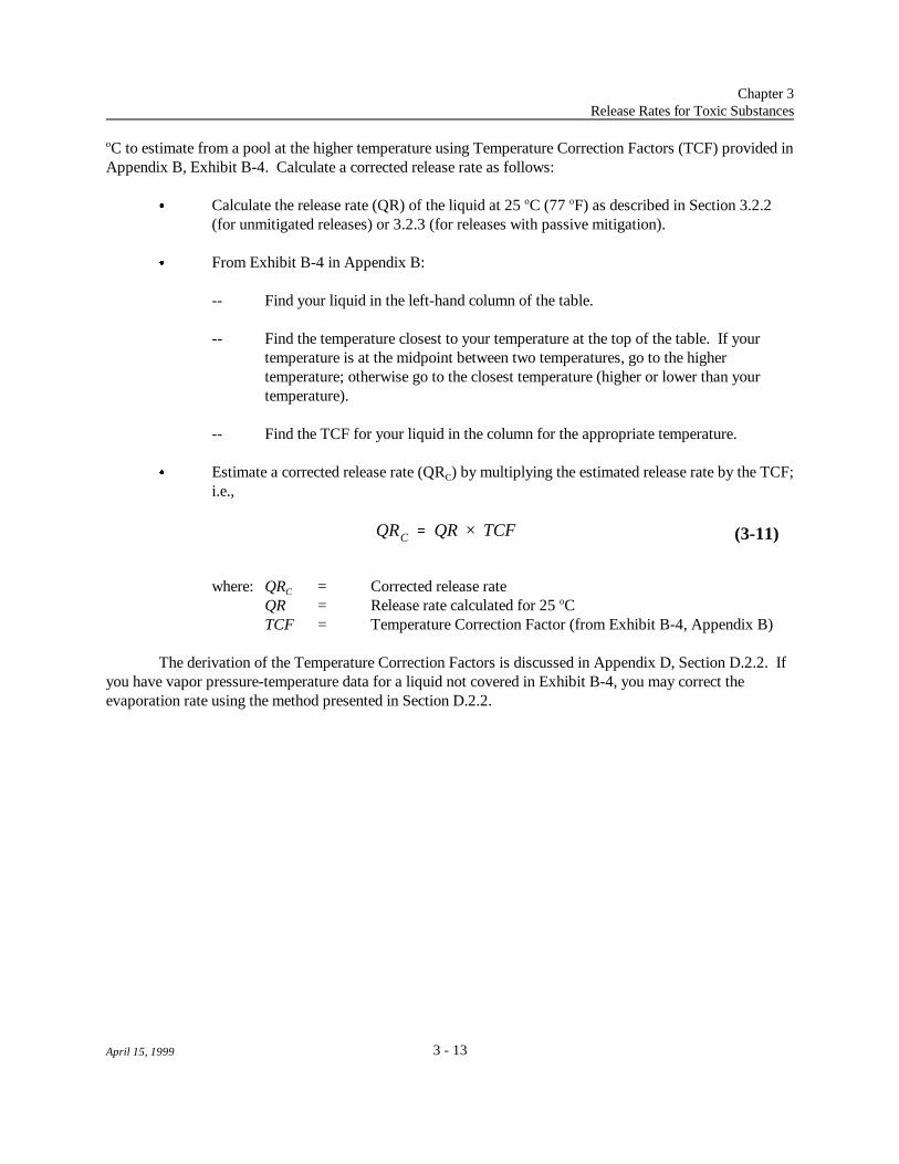
QRC QR × TCF
Chapter 3Release Rates for Toxic Substances
3 - 13April 15, 1999
(3-11)
C to estimate from a pool at the higher temperature using Temperature Correction Factors (TCF) provided ino
Appendix B, Exhibit B-4. Calculate a corrected release rate as follows:
& Calculate the release rate (QR) of the liquid at 25 C (77 F) as described in Section 3.2.2o o
(for unmitigated releases) or 3.2.3 (for releases with passive mitigation).
& From Exhibit B-4 in Appendix B:
-- Find your liquid in the left-hand column of the table.
-- Find the temperature closest to your temperature at the top of the table. If yourtemperature is at the midpoint between two temperatures, go to the highertemperature; otherwise go to the closest temperature (higher or lower than yourtemperature).
-- Find the TCF for your liquid in the column for the appropriate temperature.
& Estimate a corrected release rate (QR ) by multiplying the estimated release rate by the TCF;C
i.e.,
where: QR = Corrected release rateC
QR = Release rate calculated for 25 Co
TCF = Temperature Correction Factor (from Exhibit B-4, Appendix B)
The derivation of the Temperature Correction Factors is discussed in Appendix D, Section D.2.2. Ifyou have vapor pressure-temperature data for a liquid not covered in Exhibit B-4, you may correct theevaporation rate using the method presented in Section D.2.2.

Chapter 3Release Rates for Toxic Substances
3 - 14April 15, 1999
Example 9. Liquid Release at Ambient Temperature Between 25 C and 50 C (Bromine)o o
Assume the tank containing 20,000 pounds of bromine, from Example 6, is at an ambient temperature of 35 Co
(95 F). As in Example 6, the total quantity in the tank is spilled into a diked enclosure that completely containso
the spill. The surface area is 100 square feet. In Example 6, the release rate (QR) at 25 C was calculated fromo
Equation 3-7 to be 10 pounds per minute. To adjust the release rate for the temperature of 35 C, you find theo
Temperature Correction Factor (TCF) for bromine at 35 C from Exhibit B-4 in Appendix B. The TCF at thiso
temperature is 1.5; the corrected release rate (QR ) at 35 C, from Equation 3-11, is Co
QR = 10 × 1.5 = 15 pounds per minuteC
The duration of the release (from Equation 3-5) would be:
t = 20,000 pounds/15 pounds per minute = 1,300 minutes
In Section 3.3
& Methods to estimate the release rates for several common water solutions andfor oleum, including:
-- Evaporation from pools with no mitigation (see 3.2.2),-- Evaporation from pools with dikes (see 3.2.3),-- Releases at elevated temperatures of solutions of gases, and-- Releases at elevated temperatures of solutions of liquids.
3.3 Release Rates for Common Water Solutions of Toxic Substances and forOleum
This section presents a simple method of estimating the release rate from spills of water solutions ofseveral substances. Oleum (a solution of sulfur trioxide in sulfuric acid) also is discussed in this section.
The vapor pressure and evaporation rate of a substance in solution depends on its concentration inthe solution. If a concentrated water solution containing a volatile toxic substance is spilled, the toxicsubstance initially will evaporate more quickly than water from the spilled solution, and the vapor pressureand evaporation rate will decrease as the concentration of the toxic substance in the solution decreases. Atmuch lower concentrations, water may evaporate more quickly than the toxic substance. There is oneconcentration at which the composition of the solution does not change as evaporation occurs. For mostsituations of interest, the concentration exceeds this concentration, and the toxic substance evaporates morequickly than water.
For estimating release rates from solutions, this guidance lists liquid factors (ambient) for severalcommon water solutions at several concentrations that take into account the decrease in evaporation rate withdecreasing concentration. Exhibit B-3 in Appendix B provides LFA and DF values for several concentrations

Chapter 3Release Rates for Toxic Substances
3 - 15April 15, 1999
of ammonia, formaldehyde, hydrochloric acid, hydrofluoric acid, and nitric acid in water solution. Factors foroleum are also included in the exhibit. Chlorine dioxide also may be found in water solutions; however,solutions of chlorine dioxide commonly are below one percent concentration. Solutions below one percentconcentration do not have to be considered. Chlorine dioxide, therefore, is not included in Exhibit B-3. Thesefactors may be used to estimate an average release rate for the listed substances from a pool formed by a spillof solution. Liquid factors are provided for two different wind speeds, because the wind speed affects the rateof evaporation.
For the worst case, use the factor for a wind speed of 1.5 meters per second (3.4 miles per hour). You need to consider only the first 10 minutes of the release for solutions under ambient conditions inestimating the consequence distance, because the toxic component in a solution evaporates fastest during thefirst few minutes of a spill, when its concentration is highest. Modeling indicates that analysis consideringthe first 10 minutes of the release gives a good approximation of the overall consequences of the release. Although the toxic substance will continue to evaporate from the pool after 10 minutes, the rate ofevaporation is so much lower that it can safely be ignored in estimating the consequence distance. (SeeAppendix D, Section D.2.3, for more information.) Estimate release rates as follows:
Ambient Temperature
& Unmitigated. If no passive mitigation measures are in place, and the solution is at ambienttemperature, find the LFA at 1.5 meters per second (3.4 miles per hour) and DF for thesolution in Appendix B, Exhibit B-3. Follow the instructions for liquids presented inSection 3.2.2 above to estimate the release rate of the listed substance in solution. Use thetotal quantity of the solution as the quantity released (QS) in carrying out the calculation ofrelease rate.
& Mitigated. If passive mitigation is in place, and the solution is at ambient temperature, findthe LFA at 1.5 meters per second (3.4 miles per hour) in Appendix B, Exhibit B-3, andfollow the instructions for liquids in Section 3.2.3 above. Use the total quantity of thesolution to estimate the maximum pool area for comparison with the diked area.

Chapter 3Release Rates for Toxic Substances
3 - 16April 15, 1999
Example 10. Evaporation Rate for Water Solution at Ambient Temperature (Hydrochloric Acid)
You have a tank containing 50,000 pounds of 37 percent hydrochloric acid solution, at ambient temperature. For the worst-case analysis, you assume the entire contents of the tank is released, forming a pool. The releaseoccurs in a diked area of 9,000 square feet.
From Exhibit B-3, Appendix B, the Density Factor (DF) for 37 percent hydrochloric acid is 0.42. FromEquation 3-6, the maximum area of the pool would be 50,000 times 0.42, or 21,000 square feet. The dikedarea is smaller; therefore, the diked area should be used in the evaporation rate (release rate) calculation, usingEquation 3-7.
For the calculation using Equation 3-7, you need the pool area (9,000 square feet) and the Liquid FactorAmbient (LFA) for 37 percent hydrochloric acid; you assume a wind speed of 1.5 meters per second, so thewind speed factor is 1.4. From Exhibit B-3, Appendix B, the LFA is 0.0085. From Equation 3-7, the releaserate (QR) of hydrogen chloride from the pool is:
QR = 1.4 × 9,000 × 0.0085 = 107 pounds per minute
You do not need to consider the duration of the release, because only the first ten minutes are considered.
Elevated Temperature
& Known Vapor Pressure. If the solution is at an elevated temperature, the vapor pressure ofthe regulated substance and its release rate from the solution will be much higher. Thisguidance does not include temperature correction factors for evaporation rates of regulatedsubstances from solutions. If you know the partial vapor pressure of the toxic substance insolution at the relevant temperature, you can carry out the calculation of the release rateusing the equations in Appendix D, Sections D.2.1 and D.2.2. As for releases of solutions atambient temperature, you only need to consider the first 10 minutes of the release, becausethe evaporation rate of the toxic substance from the solution will decrease rapidly as itsconcentration decreases.
& Unknown Vapor Pressure. If you do not know the vapor pressure of the substance insolution, as a conservative approach for the worst-case analysis, use the appropriateinstructions, as follows:
-- Solutions containing substances that are gases under ambient conditions. Thelist of regulated substances includes several substances that, in their pure form, aregases under ambient conditions, but that may commonly be found in watersolutions. These substances include ammonia, formaldehyde, hydrogen chloride,and hydrogen fluoride. For a release of a solution of ammonia, formaldehyde,hydrochloric acid, or hydrofluoric acid above ambient temperature, if you do nothave vapor pressure data for the temperature of interest or prefer a simpler method,assume the quantity of the pure substance in the solution is released as a gas over 10

Chapter 3Release Rates for Toxic Substances
3 - 17April 15, 1999
Example 11. Evaporation Rate for Gas in Water Solution at Elevated Temperature (HydrochloricAcid)
You have 50,000 pounds of 37 percent hydrochloric acid solution in a high-temperature process. For theworst-case analysis, you assume the entire contents of the process vessel is released. In this case, because thesolution is at an elevated temperature, you consider the release of gaseous hydrogen chloride from the hotsolution.
The solution would contain 50,000 × 0.37 pounds of hydrogen chloride, or 18,500 pounds. You assume theentire 18,500 pounds is released over 10 minutes. From Equation 3-1, the release rate is 18,500 divided by 10,or 1,850 pounds per minute.
minutes, as discussed in Section 3.1 above. You may determine the amount of puresubstance in the solution from the concentration (e.g., a solution of 37 percenthydrochloric acid by weight would contain a quantity of hydrogen chloride equal to0.37 times the total weight of the solution).
-- Liquids in solution. If you have vapor pressure data for the liquid in solution(including nitric acid in water solution and sulfur trioxide in oleum) at thetemperature of interest, you may use that data to estimate the release rate, asdiscussed above. You only need to consider the first 10 minutes of the evaporation.
For a release of nitric acid solution at a temperature above ambient, if you do nothave vapor pressure data or prefer to use this simpler method, determine thequantity of pure nitric acid in the solution from the concentration. Assume thequantity of pure nitric acid is released at an elevated temperature and estimate arelease rate as discussed in Section 3.2 above, using the LFB. For temperaturesbetween 25 C and 50 C, you may use the LFA and the temperature correctiono o
factors for the pure substance, as described in Section 3.2.5. You do not need toestimate the duration of the release, because you only consider the first 10 minutes.
Similarly, for a release of oleum at an elevated temperature, determine the quantityof free sulfur trioxide in the oleum from the concentration and assume the sulfurtrioxide is released at an elevated temperature. Use the LFB or the LFA andtemperature correction factors for sulfur trioxide to estimate a release rate asdiscussed in Section 3.2. You only need to consider the first 10 minutes of therelease in your analysis.
For a spill of liquid in solution into a diked area, you would need to consider thetotal quantity of solution in determining whether the liquid could overflow the dikedarea (see the steps in Section 3.2.3). If you find that the liquid could overflow thedikes, you would need to consider both the quantity of pure substance remaininginside the diked area and the quantity of pure substance spilled outside the dikedarea in carrying out the release rate analysis as discussed in Section 3.2.3.

Chapter 3Release Rates for Toxic Substances
3 - 18April 15, 1999
Example 12. Evaporation Rate for Liquid in Water Solution at Elevated Temperature (Nitric Acid)
You have 18,000 pounds of 90 percent nitric acid solution in a high temperature process. The solution wouldcontain 18,000 x 0.90 pounds of nitric acid, or 16,200 pounds. You assume 16,200 pounds of pure nitric acidis released at an elevated temperature.
For the calculation using Equation 3-4, you need the quantity released (16,200); the Liquid Factor Boiling(LFB) for nitric acid (0.12 from Exhibit B-2); the Density Factor (DF) for nitric acid (0.32 from Exhibit B-2);and you assume a wind speed of 1.5 meter per second, so the wind speed factor is 1.4. From Equation 3-4, therelease rate (QR) of hot nitric acid is:
QR = 16,200 × 1.4 × 0.12 × 0.32 = 870 pounds per minute
You do not need to estimate the duration of release, because you only consider the first 10 minutes.

April 15, 1999
In Chapter 4
& Reference tables of distances for worst-case releases, including:
-- Generic reference tables (Exhibit 2), and-- Chemical-specific reference tables (Exhibit 3).
& Considerations include:
-- Gas density (neutrally buoyant or dense),-- Duration of release (10 minutes or 60 minutes),-- Topography (rural or urban).
4 ESTIMATION OF WORST-CASE DISTANCE TO TOXICENDPOINT
This guidance provides reference tables giving worst-case distances for neutrally buoyant gases andvapors and for dense gases and vapors for both rural (open) and urban (obstructed) areas. This chapterdescribes these reference tables and gives instructions to help you choose the appropriate table to estimateconsequence distances for the worst-case analysis.
Neutrally buoyant gases and vapors have approximately the same density as air, and dense gases andvapors are heavier than air. Neutrally buoyant and dense gases are dispersed in different ways when they arereleased; therefore, modeling was carried out to develop separate reference tables. These generic referencetables can be used to estimate distances using the specified toxic endpoint for each substance and theestimated release rate to air. In addition to the generic tables, chemical-specific reference tables are providedfor ammonia, chlorine, and sulfur dioxide. These chemical-specific tables were developed based on modelingcarried out for industry-specific guidance documents. All the tables were developed assuming a wind speedof 1.5 meters per second (3.4 miles per hour) and F stability. To use the reference tables, you need the worst-case release rates estimated as described in the previous sections. For liquid pool evaporation, you also needthe duration of the release. In addition, to use the generic tables, you will need to determine the appropriatetoxic endpoint and whether the gas or vapor is neutrally buoyant or dense, using the exhibits in Appendix B. You may interpolate between entries in the reference tables.
Generic reference tables are provided for both 10-minute releases and 60-minute releases. Youshould use the tables for 10-minute releases if the duration of your release is 10 minutes or less; use the tablesfor 60-minute releases if the duration of your release is more than 10 minutes. For the worst-case analysis, allreleases of toxic gases are assumed to last for 10 minutes. You need to consider the estimated duration of therelease (from Equation 3-5) for evaporation of pools of toxic liquids. For evaporation of water solutions oftoxic liquids or of oleum, you should always use the tables for 10-minute releases.
The generic reference tables of distances (Reference Tables 1-8), which should be used forsubstances other than ammonia, chlorine, and sulfur dioxide, are found at the end of Chapter 5. The generictables and the conditions for which each table are applicable are described in Exhibit 2. Chemical-specificreference tables of distances (Reference Tables 9-12) follow the generic reference tables at the end of Chapter5. Each of these chemical-specific tables includes distances for both rural and urban topography. Thesetables are described in Exhibit 3.

Chapter 4Estimation of Worst-Case Distance to Toxic Endpoint
4 - 2April 15, 1999
Remember that these reference tables provide only rough estimates, not accurate predictions, of thedistances that might be reached under worst-case conditions. In particular, although the distances in thetables are as great as 25 miles, you should bear in mind that the larger distances (more than six to ten miles)are very uncertain.
To use the reference tables of distances, follow these steps:
For Regulated Toxic Substances Other than Ammonia, Chlorine, and Sulfur Dioxide
& Find the toxic endpoint for the substance in Appendix B (Exhibit B-1 for toxic gases orExhibit B-2 for toxic liquids).
& Determine whether the table for neutrally buoyant or dense gases and vapors is appropriatefrom Appendix B (Exhibit B-1 for toxic gases or Exhibit B-2 for toxic liquids). A toxic gasthat is lighter than air may behave as a dense gas upon release if it is liquefied underpressure, because the released gas may be mixed with liquid droplets, or if it is cold.Consider the state of the released gas when you decide which table is appropriate.
& Determine whether the table for rural or urban conditions is appropriate.
-- Use the rural table if your site is in an open area with few obstructions.
-- Use the urban table if your site is in an urban or obstructed area. The urban tablesare appropriate if there are many obstructions in the area, even if it is in a remotelocation, not in a city.
& Determine whether the 10-minute table or the 60-minute table is appropriate.
-- Always use the 10-minute table for worst-case releases of toxic gases.
-- Always use the 10-minute table for worst-case releases of common water solutionsand oleum from evaporating pools, for both ambient and elevated temperatures.
-- If you estimated the release duration for an evaporating toxic liquid pool to be 10minutes or less, use the 10-minute table.
-- If you estimated the release duration for an evaporating toxic liquid pool to be morethan 10 minutes, use the 60-minute table.

Chapter 4Estimation of Worst-Case Distance to Toxic Endpoint
4 - 3April 15, 1999
Exhibit 2Generic Reference Tables of Distances for Worst-case Scenarios
Applicable Conditions Reference TableNumber
Gas or Vapor Density Topography Release Duration(minutes)
Neutrally buoyant Rural 10 1
60 2
Urban 10 3
60 4
Dense Rural 10 5
60 6
Urban 10 7
60 8
Exhibit 3Chemical-Specific Reference Tables of Distances for Worst-case Scenarios
Substance TableApplicable Conditions Reference
NumberGas or Vapor Topography Release DurationDensity (minutes)
Anhydrous ammonia Dense Rural, Urban 10 9liquefied under pressure
Non-liquefied ammonia, Neutrally buoyant Rural, Urban 10 10ammonia liquefied byrefrigeration, or aqueousammonia
Chlorine Dense Rural, Urban 10 11
Sulfur dioxide (anhydrous) Dense Rural, Urban 10 12

Chapter 4Estimation of Worst-Case Distance to Toxic Endpoint
4 - 4April 15, 1999
Neutrally Buoyant Gases or Vapors
& If Exhibit B-1 or B-2 indicates the gas or vapor should be considered neutrally buoyant, andother factors would not cause the gas or vapor to behave as a dense gas, divide the estimatedrelease rate (pounds per minute) by the toxic endpoint (milligrams per liter).
& Find the range of release rate/toxic endpoint values that includes your calculated releaserate/toxic endpoint in the first column of the appropriate table (Reference Table 1, 2, 3, or4), then find the corresponding distance to the right (see Example 13 below).
Dense Gases or Vapors
& If Exhibit B-1 or B-2 or consideration of other relevant factors indicates the substanceshould be considered a dense gas or vapor (heavier than air), find the distance in theappropriate table (Reference Table 5, 6, 7, or 8) as follows;
-- Find the toxic endpoint closest to that of the substance by reading across the top ofthe table. If the endpoint of the substance is halfway between two values on thetable, choose the value on the table that is smaller (to the left). Otherwise, choosethe closest value to the right or the left.
-- Find the release rate closest to the release rate estimated for the substance at the leftof the table. If the calculated release rate is halfway between two values on thetable, choose the release rate that is larger (farther down on the table). Otherwise,choose the closest value (up or down on the table).
-- Read across from the release rate and down from the endpoint to find the distancecorresponding to the toxic endpoint and release rate for your substance.
For Ammonia, Chlorine, or Sulfur Dioxide
& Find the appropriate chemical-specific table for your substance (see the descriptions ofReference Tables 9-12 in Exhibit 3).
-- If you have ammonia liquefied by refrigeration alone, you may use Reference Table10, even if the duration of the release is greater than 10 minutes.
-- If you have chlorine or sulfur dioxide liquefied by refrigeration alone, you may usethe chemical-specific reference tables, even if the duration of the release is greaterthan 10 minutes.
& Determine whether rural or urban topography is applicable to your site.
-- Use the rural column in the reference table if your site is in an open area with fewobstructions.

Chapter 4Estimation of Worst-Case Distance to Toxic Endpoint
4 - 5April 15, 1999
Example 13. Gas Release (Diborane)
In Example 1, you estimated a release rate for diborane gas of 250 pounds per minute. From Exhibit B-1, thetoxic endpoint for diborane is 0.0011 mg/L, and the appropriate reference table for diborane is a neutrallybuoyant gas table. Your facility and the surrounding area have many buildings, pieces of equipment, and otherobstructions; therefore, you assume urban conditions. The appropriate reference table is Reference Table 3, fora 10-minute release of a neutrally buoyant gas in an urban area.
The release rate divided by toxic endpoint for this example is 250/0.0011 = 230,000.
From Reference Table 3, release rate divided by toxic endpoint falls between 221,000 and 264,000,corresponding to about 8.1 miles.
-- Use the urban column if your site is in an urban or obstructed area. The urbancolumn is appropriate if there are many obstructions in the area, even if it is in aremote location, not in a city.
& Estimate the consequence distance as follows:
-- In the left-hand column of the table, find the release rate closest to your calculatedrelease rate.
-- Read the corresponding distance from the appropriate column (urban or rural) to theright.
The development of Reference Tables 1-8 is discussed in Appendix D, Sections D.4.1 and D.4.2. The development of Reference Tables 9-12 is discussed in industry-specific risk management programguidance documents and a backup information document that are cited in Section D.4.3. If you think theresults of the method presented here overstate the potential consequences of a worst-case release at your site,you may choose to use other methods or models that take additional site-specific factors into account.
Examples 14 and 15 below include the results of modeling using two other models, the ArealLocations of Hazardous Atmospheres (ALOHA) and the World Bank Hazards Analysis (WHAZAN)systems. These additional results are provided for comparison with the results of the methods presented inthis guidance. The same modeling parameters were used as in the modeling carried out for development ofthe reference tables of distances. Appendix D, Section D.4.5, provides information on the modeling carriedout with ALOHA and WHAZAN.

Chapter 4Estimation of Worst-Case Distance to Toxic Endpoint
4 - 6April 15, 1999
Example 14. Gas Release (Ethylene Oxide)
You have a tank containing 10,000 pounds of ethylene oxide, which is a gas under ambient conditions. Assuming the total quantity in the tank is released over a 10-minute period, the release rate (QR) from Equation3-1 is:
QR = 10,000 pounds/10 minutes = 1,000 pounds per minute
From Exhibit B-1, the toxic endpoint for ethylene oxide is 0.09 mg/L, and the appropriate reference table is thedense gas table. Your facility is in an open, rural area with few obstructions; therefore, you use the table forrural areas.
Using Reference Table 5 for 10-minute releases of dense gases in rural areas, the toxic endpoint of 0.09 mg/Lis closer to 0.1 than 0.075 mg/L. For a release rate of 1,000 pounds per minute, the distance to 0.1 mg/L is 3.6miles.
Additional Modeling for Comparison
The ALOHA model gave a distance of 2.2 miles to the endpoint, using the same assumptions.
The WHAZAN model gave a distance of 2.7 miles to the endpoint, using the same assumptions and the densecloud dispersion model.
Example 15. Liquid Evaporation from Pool (Acrylonitrile)
You estimated an evaporation rate of 307 pounds per minute for acrylonitrile from a pool formed by the releaseof 20,000 pounds into an undiked area (Example 4). You estimated the time for evaporation of the pool as 65minutes. From Exhibit B-2, the toxic endpoint for acrylonitrile is 0.076 mg/L, and the appropriate referencetable for a worst-case release of acrylonitrile is the dense gas table. Your facility is in an urban area. You useReference Table 8 for 60-minute releases of dense gases in urban areas.
From Reference Table 8, the toxic endpoint closest to 0.076 mg/L is 0.075 mg/L, and the closest release rate to307 pounds per minute is 250 pounds per minute. Using these values, the table gives a worst-caseconsequence distance of 2.9 miles.
Additional Modeling for Comparison
The ALOHA model gave a distance of 1.3 miles to the endpoint for a release rate of 307 pounds per minute,using the same assumptions.
The WHAZAN model gave a distance of 1.0 mile to the endpoint for a release rate of 307 pounds per minute,using the same assumptions and the dense cloud dispersion model.

April 15, 1999
In Chapter 5
& Methods to estimate the worst-case consequence distances for releases offlammable substances.
-- 5.1 Vapor cloud explosions of flammable substances that are notmixed with other substances, and
-- 5.2 Vapor cloud explosions of flammable substances in mixtures.
5 ESTIMATION OF DISTANCE TO OVERPRESSURE ENDPOINTFOR FLAMMABLE SUBSTANCES
For the worst-case scenario involving a release of flammable gases and volatile flammable liquids,you must assume that the total quantity of the flammable substance forms a vapor cloud within the upper andlower flammability limits and the cloud detonates. As a conservative worst-case assumption, if you use themethod presented here, you must assume that 10 percent of the flammable vapor in the cloud participates inthe explosion. You need to estimate the consequence distance to an overpressure level of 1 pound per squareinch (psi) from the explosion of the vapor cloud. An overpressure of 1 psi may cause partial demolition ofhouses, which can result in serious injuries to people, and shattering of glass windows, which may cause skinlaceration from flying glass.
This chapter presents a simple method for estimating the distance to the endpoint for a vapor cloudexplosion of a regulated substance. The method presented here for analysis of vapor cloud explosions isbased on a TNT-equivalent model. Other methods are available for analysis of vapor cloud explosions,including methods that consider site-specific conditions. You may use other methods for your worst-caseanalysis if you so choose, provided you assume the total quantity of flammable substance is in the cloud anduse an endpoint of 1 psi. If you use a TNT-equivalent model, you must assume a yield factor of 10 percent. Appendix A includes references to documents and journal articles on vapor cloud explosions that mayprovide useful information on methods of analysis.
5.1 Flammable Substances Not in Mixtures
For the worst-case analysis of a regulated flammable substance that is not in a mixture with othersubstances, you may estimate the consequence distance for a given quantity of a regulated flammablesubstance using Reference Table 13. This table provides distances to 1 psi overpressure for vapor cloudexplosions of quantities from 500 to 2,000,000 pounds. These distances were estimated by a TNT-equivalent model, Equation C-1 in Appendix C, Section C.1, using the worst-case assumptions describedabove and data provided in Exhibit C-1, Appendix C. If you prefer, you may calculate your worst-caseconsequence distance for flammable substances from the heat of combustion of the flammable substance andEquation C-1 or C-2.

Chapter 5Estimation of Distance to Overpressure Endpoint for Flammable Substances
5 - 2April 15, 1999
Example 16. Vapor Cloud Explosion (Propane)
You have a tank containing 50,000 pounds of propane. From Reference Table 13, the distance to 1 psioverpressure is 0.3 miles for 50,000 pounds of propane.
Alternatively, you can calculate the distance to 1 psi using Equation C-2 from Appendix C:
D = 0.0081 × [ 0.1 × 50,000 × (46,333/4,680) ]1/3
D = 0.3 miles
5.2 Flammable Mixtures
If you have more than 10,000 pounds of a mixture of flammable substances that meets the criteriafor listing under CAA section 112(r) (flash point below 22.8 C (73 F), boiling point below 37.8 C (100o o o
F), National Fire Protection Association (NFPA) flammability hazard rating of 4), you may need to carry outo
a worst-case consequence analysis for the mixture. (If the mixture itself does not meet these criteria, it is notcovered, and no analysis is required, even if the mixture contains one or more regulated substances.) Youshould carry out the analysis using the total quantity of all regulated flammable substance or substances in themixture. Non-flammable components should not be included. However, if additional (non-regulated)flammable substances are present in the mixture, you should include them in the quantity used in the analysis.
For simplicity, you may carry out the worst-case analysis based on the predominant regulatedflammable component of the mixture or a major component of the mixture with the highest heat ofcombustion if the whole vapor cloud consists of flammable substances (see Exhibit C-1, Appendix C for dataon heat of combustion). Estimate the consequence distance from Reference Table 13 for the majorcomponent with the highest heat of combustion, assuming that the quantity in the cloud is the total quantityof the mixture. If you have a mixture in which the heats of combustion of the components do not differsignificantly (e.g., a mixture of hydrocarbons), this method is likely to give reasonable results.
Alternatively, you may estimate the heat of combustion of the mixture from the heats of combustionof the components of the mixture using the method described in Appendix C, Section C.2, and then useEquation C-1 or C-2 in Appendix C to determine the vapor cloud explosion distance. This method may beappropriate if you have a mixture that includes components with significantly different heats of combustion(e.g., a mixture of hydrogen and hydrocarbons) that make up a significant portion of the mixture.
Examples 17 and 18 illustrate the two methods of analysis. In Example 17, the heat of combustionof the mixture is estimated, and the distance to the endpoint is calculated from Equation C-2. In Example 18,the component of the mixture with the highest heat of combustion is assumed to represent the entire mixture,and the distance to the endpoint is read from Reference Table 13. For the mixture of two hydrocarbons usedin the example, the methods give very similar results.

Chapter 5Estimation of Distance to Overpressure Endpoint for Flammable Substances
5 - 3April 15, 1999
Example 17. Estimating Heat of Combustion of Mixture for Vapor Cloud Explosion Analysis
You have a mixture of 8,000 pounds of ethylene (the reactant) and 2,000 pounds of isobutane (a catalystcarrier). To carry out the worst-case analysis, estimate the heat of combustion of the mixture from the heats ofcombustion of the components of the mixture. (Ethylene heat of combustion = 47,145 kilojoules per kilogram;isobutane heat of combustion = 45,576). Using Equation C-3, Appendix C:
HC = [ (8,000/2.2) × 47,145 ] + [ (2,000/2.2) × 45,576 ]m
(10,000/2.2) (10,000/2.2)
HC = (37,716) + (9,115)m
HC = 46,831 kilojoules per kilogramm
Now use the calculated heat of combustion for the mixture in Equation C-2 to calculate the distance to 1 psioverpressure for vapor cloud explosion.
D = 0.0081 × [ 0.1 × 10,000 × (46,831/4,680) ]D
D = 0.2 miles
Example 18. Vapor Cloud Explosion of Flammable Mixture (Ethylene and Isobutane)
You have 10,000 pounds of a mixture of ethylene (the reactant) and isobutane (a catalyst carrier). To carry outthe worst-case analysis, assume the quantity in the cloud is the total quantity of the mixture. Use data forethylene because it is the component with the highest heat of combustion. (Ethylene heat of combustion =47,145 kilojoules per kilogram; isobutane heat of combustion = 45,576, from Exhibit C-1, Appendix C). FromReference Table 13, the distance to 1 psi overpressure is 0.2 miles for 10,000 pounds of ethylene; this distancewould also apply to the 10,000-pound mixture of ethylene and isobutane.

5 - 4April 15, 1999
Reference Table 1Neutrally Buoyant Plume Distances to Toxic Endpoint for Release Rate Divided by Endpoint
10-Minute Release, Rural Conditions, F Stability, Wind Speed 1.5 Meters per Second
Release Rate/Endpoint Distance to Release Rate/Endpoint Distance to[(lbs/min)/(mg/L)] Endpoint [(lbs/min)/(mg/L)] Endpoint
(miles) (miles)
0 - 4.4 0.1 16,000 - 18,000 4.8
4.4 - 37 0.2 18,000 - 19,000 5.0
37 - 97 0.3 19,000 - 21,000 5.2
97 - 180 0.4 21,000 - 23,000 5.4
180 - 340 0.6 23,000 - 24,000 5.6
340 - 530 0.8 24,000 - 26,000 5.8
530 - 760 1.0 26,000 - 28,000 6.0
760 - 1,000 1.2 28,000 - 29,600 6.2
1,000 - 1,500 1.4 29,600 - 35,600 6.8
1,500 - 1,900 1.6 35,600 - 42,000 7.5
1,900 - 2,400 1.8 42,000 - 48,800 8.1
2,400 - 2,900 2.0 48,800 - 56,000 8.7
2,900 - 3,500 2.2 56,000 - 63,600 9.3
3,500 - 4,400 2.4 63,600 - 71,500 9.9
4,400 - 5,100 2.6 71,500 - 88,500 11
5,100 - 5,900 2.8 88,500 - 107,000 12
5,900 - 6,800 3.0 107,000 - 126,000 14
6,800 - 7,700 3.2 126,000 - 147,000 15
7,700 - 9,000 3.4 147,000 - 169,000 16
9,000 - 10,000 3.6 169,000 - 191,000 17
10,000 - 11,000 3.8 191,000 - 215,000 19
11,000 - 12,000 4.0 215,000 - 279,000 22
12,000 - 14,000 4.2 279,000 - 347,000 25
14,000 - 15,000 4.4 >347,000 >25*
15,000 - 16,000 4.6
*Report distance as 25 miles

5 - 5April 15, 1999
Reference Table 2Neutrally Buoyant Plume Distances to Toxic Endpoint for Release Rate Divided by Endpoint
60-Minute Release, Rural Conditions, F Stability, Wind Speed 1.5 Meters per Second
Release Rate/Endpoint Distance to Release Rate/Endpoint Distance to[(lbs/min)/(mg/L)] Endpoint [(lbs/min)/(mg/L)] Endpoint
(miles) (miles)
0 - 5.5 0.1 7,400 - 7,700 4.8
5.5 - 46 0.2 7,700 - 8,100 5.0
46 - 120 0.3 8,100 - 8,500 5.2
120 - 220 0.4 8,500 - 8,900 5.4
220 - 420 0.6 8,900 - 9,200 5.6
420 - 650 0.8 9,200 - 9,600 5.8
650 - 910 1.0 9,600 - 10,000 6.0
910 - 1,200 1.2 10,000 - 10,400 6.2
1,200 - 1,600 1.4 10,400 - 11,700 6.8
1,600 - 1,900 1.6 11,700 - 13,100 7.5
1,900 - 2,300 1.8 13,100 - 14,500 8.1
2,300 - 2,600 2.0 14,500 - 15,900 8.7
2,600 - 2,900 2.2 15,900 - 17,500 9.3
2,900 - 3,400 2.4 17,500 - 19,100 9.9
3,400 - 3,700 2.6 19,100 - 22,600 11
3,700 - 4,100 2.8 22,600 - 26,300 12
4,100 - 4,400 3.0 26,300 - 30,300 14
4,400 - 4,800 3.2 30,300 - 34,500 15
4,800 - 5,200 3.4 34,500 - 38,900 16
5,200 - 5,600 3.6 38,900 - 43,600 17
5,600 - 5,900 3.8 43,600 - 48,400 19
5,900 - 6,200 4.0 48,400 - 61,500 22
6,200 - 6,700 4.2 61,500 - 75,600 25
6,700 - 7,000 4.4 >75,600 >25*
7,000 - 7,400 4.6
*Report distance as 25 miles

5 - 6April 15, 1999
Reference Table 3Neutrally Buoyant Plume Distances to Toxic Endpoint for Release Rate Divided by Endpoint
10-minute Release, Urban Conditions, F Stability, Wind Speed 1.5 Meters per Second
Release Rate/Endpoint Distance to Release Rate/Endpoint Distance to[(lbs/min)/(mg/L)] Endpoint [(lbs/min)/(mg/L)] Endpoint
(miles) (miles)
0 - 21 0.1 76,000 - 83,000 4.8
21 - 170 0.2 83,000 - 90,000 5.0
170 - 420 0.3 90,000 - 100,000 5.2
420 - 760 0.4 100,000 - 110,000 5.4
760 - 1,400 0.6 110,000 - 120,000 5.6
1,400 - 2,100 0.8 120,000 - 130,000 5.8
2,100 - 3,100 1.0 130,000 - 140,000 6.0
3,100 - 4,200 1.2 140,000 - 148,000 6.2
4,200 - 6,100 1.4 148,000 - 183,000 6.8
6,100 - 7,800 1.6 183,000 - 221,000 7.5
7,800 - 9,700 1.8 221,000 - 264,000 8.1
9,700 - 12,000 2.0 264,000 - 310,000 8.7
12,000 - 14,000 2.2 310,000 - 361,000 9.3
14,000 - 18,000 2.4 361,000 - 415,000 9.9
18,000 - 22,000 2.6 415,000 - 535,000 11
22,000 - 25,000 2.8 535,000 - 671,000 12
25,000 - 29,000 3.0 671,000 - 822,000 14
29,000 - 33,000 3.2 822,000 - 990,000 15
33,000 - 39,000 3.4 990,000 - 1,170,000 16
39,000 - 44,000 3.6 1,170,000 - 1,370,000 17
44,000 - 49,000 3.8 1,370,000 - 1,590,000 19
49,000 - 55,000 4.0 1,590,000 - 2,190,000 22
55,000 - 63,000 4.2 2,190,000 - 2,890,000 25
63,000 - 69,000 4.4 >2,890,000 >25*
69,000 - 76,000 4.6
*Report distance as 25 miles

5 - 7April 15, 1999
Reference Table 4Neutrally Buoyant Plume Distances to Toxic Endpoint for Release Rate Divided by Endpoint
60-Minute Release, Urban Conditions, F Stability, Wind Speed 1.5 Meters per Second
Release Rate/Endpoint Distance to Release Rate/Endpoint Distance to[(lbs/min)/(mg/L)] Endpoint [(lbs/min)/(mg/L)] Endpoint
(miles) (miles)
0 - 26 0.1 34,000 - 36,000 4.8
26 - 210 0.2 36,000 - 38,000 5.0
210 - 530 0.3 38,000 - 41,000 5.2
530 - 940 0.4 41,000 - 43,000 5.4
940 - 1,700 0.6 43,000 - 45,000 5.6
1,700 - 2,600 0.8 45,000 - 47,000 5.8
2,600 - 3,700 1.0 47,000 - 50,000 6.0
3,700 - 4,800 1.2 50,000 - 52,200 6.2
4,800 - 6,400 1.4 52,200 - 60,200 6.8
6,400 - 7,700 1.6 60,200 - 68,900 7.5
7,700 - 9,100 1.8 68,900 - 78,300 8.1
9,100 - 11,000 2.0 78,300 - 88,400 8.7
11,000 - 12,000 2.2 88,400 - 99,300 9.3
12,000 - 14,000 2.4 99,300 - 111,000 9.9
14,000 - 16,000 2.6 111,000 - 137,000 11
16,000 - 17,000 2.8 137,000 - 165,000 12
17,000 - 19,000 3.0 165,000 - 197,000 14
19,000 - 21,000 3.2 197,000 - 232,000 15
21,000 - 23,000 3.4 232,000 - 271,000 16
23,000 - 24,000 3.6 271,000 - 312,000 17
24,000 - 26,000 3.8 312,000 - 357,000 19
26,000 - 28,000 4.0 357,000 - 483,000 22
28,000 - 30,000 4.2 483,000 - 629,000 25
30,000 - 32,000 4.4 >629,000 >25*
32,000 - 34,000 4.6
*Report distance as 25 miles

5 - 8
Reference Table 5Dense Gas Distances to Toxic Endpoint
10-minute Release, Rural Conditions, F Stability, Wind Speed 1.5 Meters per Second
ReleaseRate
(lbs/min)
Toxic Endpoint (mg/L)
0.0004 0.0007 0.001 0.002 0.0035 0.005 0.0075 0.01 0.02 0.035 0.05 0.075 0.1 0.25 0.5 0.75
Distance (Miles)
1 2.2 1.7 1.5 1.1 0.8 0.7 0.5 0.5 0.3 0.2 0.2 0.2 0.1 0.1 # #
2 3.0 2.4 2.1 1.5 1.1 0.9 0.7 0.7 0.4 0.3 0.3 0.2 0.2 0.1 <0.1 <0.1
5 4.8 3.7 3.0 2.2 1.7 1.5 1.2 1.0 0.7 0.5 0.4 0.3 0.3 0.2 0.1 0.1
10 6.8 5.0 4.2 3.0 2.4 2.1 1.7 1.4 1.0 0.7 0.6 0.5 0.4 0.2 0.2 0.1
30 11 8.7 6.8 5.2 3.9 3.4 2.8 2.4 1.7 1.3 1.1 0.9 0.7 0.4 0.3 0.2
50 14 11 9.3 6.8 5.0 4.2 3.5 3.0 2.2 1.7 1.4 1.1 0.9 0.6 0.4 0.3
100 19 15 12 8.7 6.8 5.8 4.8 4.2 2.9 2.2 1.9 1.6 1.3 0.8 0.5 0.4
150 24 18 15 11 8.1 6.8 5.7 5.0 3.6 2.7 2.3 1.9 1.6 0.9 0.6 0.5
250 >25 22 19 14 11 8.7 7.4 6.2 4.5 3.4 2.8 2.3 2.0 1.2 0.8 0.6
500 * >25 >25 19 14 12 9.9 8.7 6.2 4.7 3.8 3.1 2.7 1.6 1.1 0.9
750 * * * 23 17 15 12 11 7.4 5.5 4.5 3.7 3.2 1.9 1.3 1.0
1,000 * * * >25 20 17 14 12 8.1 6.2 5.2 4.2 3.6 2.2 1.4 1.1
1,500 * * * * 24 20 16 14 9.9 7.4 6.2 5.0 4.3 2.5 1.7 1.3
2,000 * * * * >25 23 19 16 11 8.7 6.8 5.6 4.8 2.9 1.9 1.5
2,500 * * * * * >25 20 18 12 9.3 8.1 6.2 5.3 3.2 2.1 1.6
3,000 * * * * * * 23 20 14 9.9 8.7 6.8 5.6 3.4 2.2 1.7
4,000 * * * * * * >25 22 16 11 9.3 7.4 6.2 3.8 2.5 2.0
5,000 * * * * * * * 25 17 13 11 8.7 6.8 4.2 2.7 2.1
7,500 * * * * * * * >25 20 15 12 9.9 8.7 4.9 3.2 2.5
10,000 * * * * * * * * 24 17 14 11 9.3 5.5 3.6 2.8
15,000 * * * * * * * * >25 20 17 13 11 6.2 4.2 3.2
20,000 * * * * * * * * * 23 19 15 12 7.4 4.7 3.7
50,000 * * * * * * * * * >25 >25 21 18 10 6.6 5.0
75,000 * * * * * * * * * * * >25 21 12 7.6 5.8
100,000 * * * * * * * * * * * * 24 13 8.5 6.4
150,000 * * * * * * * * * * * * >25 15 9.8 7.4
200,000 * * * * * * * * * * * * * 17 11 8.2
* > 25 miles (report distance as 25 miles) # <0.1 mile (report distance as 0.1 mile)

5 - 9
Reference Table 6Dense Gas Distances to Toxic Endpoint
60-minute Release, Rural Conditions, F Stability, Wind Speed 1.5 Meters per Second
ReleaseRate
(lbs/min)
Toxic Endpoint (mg/L)
0.0004 0.0007 0.001 0.002 0.0035 0.005 0.0075 0.01 0.02 0.035 0.05 0.075 0.1 0.25 0.5 0.75
Distance (Miles)
1 3.7 2.7 2.2 1.4 1.0 0.8 0.6 0.5 0.3 0.2 0.2 0.1 0.1 <0.1 # #
2 5.3 4.0 3.2 2.2 1.6 1.2 1.0 0.8 0.5 0.4 0.3 0.2 0.2 0.1 <0.1 <0.1
5 8.7 6.8 5.3 3.7 2.7 2.2 1.7 1.4 0.9 0.6 0.5 0.4 0.3 0.2 0.1 0.1
10 12 9.3 8.1 5.3 4.0 3.3 2.7 2.2 1.4 1.0 0.8 0.6 0.5 0.3 0.2 0.1
30 22 16 14 9.9 7.4 6.1 4.9 4.1 2.9 2.1 1.6 1.2 1.0 0.5 0.3 0.2
50 >25 21 18 12 9.3 8.1 6.2 5.4 3.8 2.7 2.2 1.7 1.4 0.7 0.4 0.3
100 * >25 >25 18 13 11 9.3 7.4 5.5 4.0 3.2 2.5 2.1 1.1 0.7 0.5
150 * * * 22 17 14 11 9.9 6.8 4.9 4.0 3.1 2.7 1.4 0.9 0.6
250 * * * >25 22 18 14 12 8.7 6.2 5.2 4.1 3.5 1.9 1.2 0.9
500 * * * * >25 25 20 17 12 9.3 7.4 5.8 5.0 2.9 1.8 1.3
750 * * * * * >25 25 22 15 11 9.3 7.4 6.1 3.5 2.2 1.7
1,000 * * * * * * >25 25 17 12 11 8.1 6.8 4.0 2.6 2.0
1,500 * * * * * * * >25 20 16 12 9.9 8.7 5.0 3.2 2.5
2,000 * * * * * * * * 24 17 14 11 9.9 5.7 3.7 2.9
2,500 * * * * * * * * >25 20 16 13 11 6.2 4.2 3.2
3,000 * * * * * * * * * 21 17 14 12 6.8 4.5 3.5
4,000 * * * * * * * * * 24 20 16 14 8.1 5.2 4.0
5,000 * * * * * * * * * >25 22 17 15 8.7 5.7 4.4
7,500 * * * * * * * * * * >25 21 18 11 6.8 5.2
10,000 * * * * * * * * * * * 24 20 12 7.4 6.0
15,000 * * * * * * * * * * * >25 24 14 9.3 6.8
20,000 * * * * * * * * * * * * >25 16 9.9 8.1
50,000 * * * * * * * * * * * * * 22 14 11
75,000 * * * * * * * * * * * * * >25 17 13
100,000 * * * * * * * * * * * * * * 18 14
150,000 * * * * * * * * * * * * * * 21 16
200,000 * * * * * * * * * * * * * * 23 18
* > 25 miles (report distance as 25 miles) # <0.1 mile (report distance as 0.1 mile)

5 - 10
Reference Table 7Dense Gas Distances to Toxic Endpoint
10-minute Release, Urban Conditions, F Stability, Wind Speed 1.5 Meters per Second
ReleaseRate
(lbs/min)
Toxic Endpoint (mg/L)
0.0004 0.0007 0.001 0.002 0.0035 0.005 0.0075 0.01 0.02 0.035 0.05 0.075 0.1 0.25 0.5 0.75
Distance (Miles)
1 1.6 1.2 1.1 0.7 0.6 0.4 0.4 0.3 0.2 0.2 0.1 0.1 0.1 # # #
2 2.2 1.7 1.4 1.1 0.8 0.6 0.5 0.4 0.3 0.2 0.2 0.1 0.1 <0.1 # #
5 3.5 2.7 2.2 1.6 1.2 1.0 0.8 0.7 0.5 0.4 0.3 0.2 0.2 0.1 <0.1 #
10 4.9 3.8 3.1 2.2 1.7 1.4 1.2 1.0 0.7 0.5 0.4 0.3 0.2 0.1 0.1 <0.1
30 8.1 6.2 5.3 3.7 2.9 2.4 2.0 1.7 1.2 0.9 0.7 0.6 0.4 0.2 0.1 0.1
50 11 8.1 6.8 4.8 3.7 3.1 2.5 2.1 1.5 1.1 0.9 0.7 0.6 0.3 0.2 0.1
100 15 11 9.3 6.8 5.2 4.2 3.5 3.0 2.1 1.6 1.3 1.0 0.9 0.5 0.3 0.2
150 19 14 12 8.1 6.1 5.2 4.3 3.6 2.5 1.9 1.6 1.2 1.1 0.6 0.4 0.2
250 24 18 15 11 8.1 6.8 5.4 4.6 3.3 2.4 2.0 1.6 1.4 0.7 0.5 0.3
500 >25 >25 21 15 11 9.3 7.4 6.2 4.5 3.4 2.8 2.2 1.9 1.1 0.7 0.5
750 * * >25 18 14 11 9.3 8.1 5.5 4.1 3.3 2.6 2.2 1.3 0.8 0.6
1,000 * * * 21 16 13 11 9.3 6.2 4.6 3.8 3.0 2.5 1.5 0.9 0.7
1,500 * * * >25 19 16 12 11 7.4 5.6 4.6 3.7 3.0 1.7 1.1 0.8
2,000 * * * * 22 18 15 12 8.7 6.2 5.2 4.1 3.5 2.0 1.3 0.9
2,500 * * * * 24 20 16 14 9.9 6.8 5.8 4.7 3.8 2.2 1.4 1.1
3,000 * * * * >25 22 18 16 11 7.4 6.2 5.0 4.2 2.4 1.6 1.2
4,000 * * * * * 25 20 17 12 8.7 6.8 5.6 4.8 2.7 1.7 1.3
5,000 * * * * * >25 23 20 14 9.9 8.1 6.2 5.3 3.0 1.9 1.4
7,500 * * * * * * >25 24 16 12 9.9 7.4 6.2 3.6 2.3 1.7
10,000 * * * * * * * >25 19 14 11 8.7 7.4 4.1 2.6 2.0
15,000 * * * * * * * * 22 16 13 11 8.7 4.9 3.1 2.3
20,000 * * * * * * * * >25 19 15 12 9.9 5.5 3.5 2.7
50,000 * * * * * * * * * >25 23 17 15 8.1 5.1 3.8
75,000 * * * * * * * * * * >25 21 17 9.6 6.0 4.5
100,000 * * * * * * * * * * * 24 20 11 6.8 5.1
150,000 * * * * * * * * * * * >25 23 13 8.1 6.1
200,000 * * * * * * * * * * * * >25 14 8.9 6.7
* > 25 miles (report distance as 25 miles) # <0.1 mile (report distance as 0.1 mile)

5 - 11
Reference Table 8Dense Gas Distances to Toxic Endpoint
60-minute Release, Urban Conditions, F Stability, Wind Speed 1.5 Meters per Second
ReleaseRate
(lbs/min)
Toxic Endpoint (mg/L)
0.0004 0.0007 0.001 0.002 0.0035 0.005 0.0075 0.01 0.02 0.035 0.05 0.075 0.1 0.25 0.5 0.75
Distance (Miles)
1 2.6 1.9 1.5 1.1 0.7 0.6 0.4 0.4 0.2 0.2 0.1 0.1 0.1 # # #
2 3.8 2.9 2.3 1.5 1.1 0.9 0.7 0.6 0.4 0.2 0.2 0.1 0.1 <0.1 # #
5 6.2 4.7 3.9 2.6 1.9 1.5 1.2 0.9 0.6 0.4 0.3 0.2 0.2 0.1 <0.1 #
10 9.3 6.8 5.6 3.9 2.9 2.3 1.8 1.5 0.9 0.7 0.5 0.4 0.3 0.2 0.1 <0.1
30 16 12 9.9 7.4 5.3 4.3 3.4 2.9 1.9 1.3 1.0 0.7 0.6 0.3 0.2 0.1
50 22 16 14 9.3 6.8 5.7 4.5 3.8 2.6 1.8 1.4 1.1 0.9 0.4 0.2 0.2
100 >25 24 20 14 9.9 8.1 6.8 5.7 3.8 2.7 2.2 1.7 1.4 0.7 0.4 0.3
150 * >25 24 17 12 11 8.1 6.8 4.8 3.5 2.8 2.2 1.8 0.9 0.5 0.3
250 * * >25 22 16 14 11 9.3 6.2 4.5 3.7 2.9 2.4 1.2 0.7 0.5
500 * * * >25 24 19 16 13 9.3 6.8 5.4 4.2 3.5 1.9 1.1 0.7
750 * * * * >25 24 19 16 11 8.1 6.8 5.2 4.3 2.4 1.4 1.0
1,000 * * * * * >25 22 19 13 9.3 7.4 6.0 5.0 2.8 1.6 1.2
1,500 * * * * * * >25 24 16 12 9.3 7.4 6.2 3.4 2.1 1.5
2,000 * * * * * * * >25 19 13 11 8.7 7.4 4.0 2.5 1.8
2,500 * * * * * * * * 20 15 12 9.3 8.1 4.5 2.8 2.1
3,000 * * * * * * * * 22 16 13 11 8.7 4.9 3.0 2.2
4,000 * * * * * * * * >25 19 16 12 9.9 5.6 3.5 2.6
5,000 * * * * * * * * * 21 17 14 11 6.2 4.0 3.0
7,500 * * * * * * * * * >25 20 16 14 7.4 4.8 3.6
10,000 * * * * * * * * * * 24 19 16 8.7 5.5 4.2
15,000 * * * * * * * * * * >25 22 19 11 6.8 5.1
20,000 * * * * * * * * * * * >25 21 12 7.4 5.8
50,000 * * * * * * * * * * * * >25 18 11 8.7
75,000 * * * * * * * * * * * * * 21 13 10
100,000 * * * * * * * * * * * * * 24 15 11
150,000 * * * * * * * * * * * * * >25 18 14
200,000 * * * * * * * * * * * * * * 20 15
* > 25 miles (report distance as 25 miles) # <0.1 mile (report distance as 0.1 mile)

5 - 12April 15, 1999
Reference Table 9Distances to Toxic Endpoint for Anhydrous Ammonia Liquefied Under Pressure
F Stability, Wind Speed 1.5 Meters per Second
Release Rate Distance to Endpoint (miles) Release Rate Distance to Endpoint (miles)(lbs/min) (lbs/min)
Rural Urban Rural Urban
1 0.1 <0.1* 1,000 1.8 1.2
2 0.1 0.1 1,500 2.2 1.5
5 0.1 0.1 2,000 2.6 1.7
10 0.2 0.1 2,500 2.9 1.9
15 0.2 0.2 3,000 3.1 2.0
20 0.3 0.2 4,000 3.6 2.3
30 0.3 0.2 5,000 4.0 2.6
40 0.4 0.3 6,000 4.4 2.8
50 0.4 0.3 7,000 4.7 3.1
60 0.5 0.3 7,500 4.9 3.2
70 0.5 0.3 8,000 5.1 3.3
80 0.5 0.4 9,000 5.4 3.4
90 0.6 0.4 10,000 5.6 3.6
100 0.6 0.4 15,000 6.9 4.4
150 0.7 0.5 20,000 8.0 5.0
200 0.8 0.6 25,000 8.9 5.6
250 0.9 0.6 30,000 9.7 6.1
300 1.0 0.7 40,000 11 7.0
400 1.2 0.8 50,000 12 7.8
500 1.3 0.9 75,000 15 9.5
600 1.4 0.9 100,000 18 10
700 1.5 1.0 150,000 22 13
750 1.6 1.0 200,000 ** 15
800 1.6 1.1 250,000 ** 17
900 1.7 1.2 750,000 ** **
*Report distance as 0.1 mile ** More than 25 miles (report distance as 25 miles)
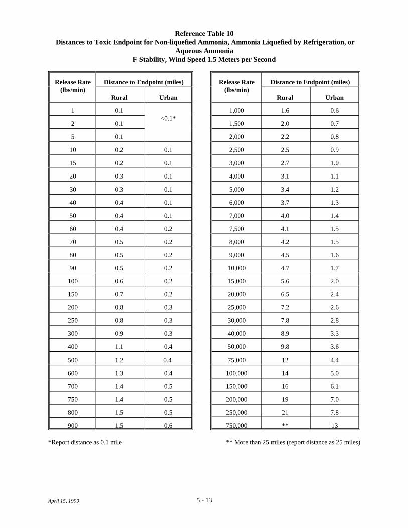
5 - 13April 15, 1999
Reference Table 10 Distances to Toxic Endpoint for Non-liquefied Ammonia, Ammonia Liquefied by Refrigeration, or
Aqueous AmmoniaF Stability, Wind Speed 1.5 Meters per Second
Release Rate Distance to Endpoint (miles) Release Rate Distance to Endpoint (miles)(lbs/min) (lbs/min)
Rural Urban Rural Urban
1 0.1 1,000 1.6 0.6<0.1*
2 0.1 1,500 2.0 0.7
5 0.1 2,000 2.2 0.8
10 0.2 0.1 2,500 2.5 0.9
15 0.2 0.1 3,000 2.7 1.0
20 0.3 0.1 4,000 3.1 1.1
30 0.3 0.1 5,000 3.4 1.2
40 0.4 0.1 6,000 3.7 1.3
50 0.4 0.1 7,000 4.0 1.4
60 0.4 0.2 7,500 4.1 1.5
70 0.5 0.2 8,000 4.2 1.5
80 0.5 0.2 9,000 4.5 1.6
90 0.5 0.2 10,000 4.7 1.7
100 0.6 0.2 15,000 5.6 2.0
150 0.7 0.2 20,000 6.5 2.4
200 0.8 0.3 25,000 7.2 2.6
250 0.8 0.3 30,000 7.8 2.8
300 0.9 0.3 40,000 8.9 3.3
400 1.1 0.4 50,000 9.8 3.6
500 1.2 0.4 75,000 12 4.4
600 1.3 0.4 100,000 14 5.0
700 1.4 0.5 150,000 16 6.1
750 1.4 0.5 200,000 19 7.0
800 1.5 0.5 250,000 21 7.8
900 1.5 0.6 750,000 ** 13
*Report distance as 0.1 mile ** More than 25 miles (report distance as 25 miles)

5 - 14April 15, 1999
Reference Table 11Distances to Toxic Endpoint for Chlorine
F Stability, Wind Speed 1.5 Meters per Second
Release Rate Distance to Endpoint (miles) Release Rate Distance to Endpoint (miles)(lbs/min) (lbs/min)
Rural Urban Rural Urban
1 0.2 0.1 750 5.8 2.6
2 0.3 0.1 800 5.9 2.7
5 0.5 0.2 900 6.3 2.9
10 0.7 0.3 1,000 6.6 3.0
15 0.8 0.4 1,500 8.1 3.8
20 1.0 0.4 2,000 9.3 4.4
30 1.2 0.5 2,500 10 4.9
40 1.4 0.6 3,000 11 5.4
50 1.5 0.6 4,000 13 6.2
60 1.7 0.7 5,000 14 7.0
70 1.8 0.8 6,000 16 7.6
80 1.9 0.8 7,000 17 8.3
90 2.0 0.9 7,500 18 8.6
100 2.2 0.9 8,000 18 8.9
150 2.6 1.2 9,000 19 9.4
200 3.0 1.3 10,000 20 9.9
250 3.4 1.5 15,000 25 12
300 3.7 1.6 20,000 * 14
400 4.2 1.9 25,000 * 16
500 4.7 2.1 30,000 * 18
600 5.2 2.3 40,000 * 20
700 5.6 2.5 50,000 * *
* More than 25 miles (report distance as 25 miles)

5 - 15April 15, 1999
Reference Table 12 Distances to Toxic Endpoint for Anhydrous Sulfur Dioxide
F Stability, Wind Speed 1.5 Meters per Second
Release Rate Distance to Endpoint (miles) Release Rate Distance to Endpoint (miles)(lbs/min) (lbs/min)
Rural Urban Rural Urban
1 0.2 0.1 750 6.6 2.6
2 0.2 0.1 800 6.8 2.7
5 0.4 0.2 900 7.2 2.9
10 0.6 0.2 1,000 7.7 3.1
15 0.7 0.3 1,500 9.6 3.8
20 0.9 0.4 2,000 11 4.5
30 1.1 0.5 2,500 13 5.0
40 1.3 0.5 3,000 14 5.6
50 1.4 0.6 4,000 17 6.5
60 1.6 0.7 5,000 19 7.3
70 1.8 0.7 6,000 21 8.1
80 1.9 0.8 7,000 23 8.8
90 2.0 0.8 7,500 24 9.1
100 2.1 0.9 8,000 25 9.5
150 2.7 1.1 9,000 * 10
200 3.1 1.3 10,000 * 11
250 3.6 1.4 15,000 * 13
300 3.9 1.6 20,000 * 16
400 4.6 1.9 25,000 * 18
500 5.2 2.1 30,000 * 19
600 5.8 2.3 40,000 * 23
700 6.3 2.5 50,000 * *
* More than 25 miles (report distance as 25 miles)
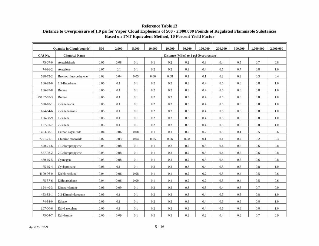
5 - 16April 15, 1999
Reference Table 13Distance to Overpressure of 1.0 psi for Vapor Cloud Explosions of 500 - 2,000,000 Pounds of Regulated Flammable Substances
Based on TNT Equivalent Method, 10 Percent Yield Factor
Quantity in Cloud (pounds) 500 2,000 5,000 10,000 20,000 50,000 100,000 200,000 500,000 1,000,000 2,000,000
CAS No. Chemical Name Distance (Miles) to 1 psi Overpressure
75-07-0 Acetaldehyde 0.05 0.08 0.1 0.1 0.2 0.2 0.3 0.4 0.5 0.7 0.8
74-86-2 Acetylene 0.07 0.1 0.1 0.2 0.2 0.3 0.4 0.5 0.7 0.8 1.0
598-73-2 Bromotrifluoroethylene 0.02 0.04 0.05 0.06 0.08 0.1 0.1 0.2 0.2 0.3 0.4
106-99-0 1,3-Butadiene 0.06 0.1 0.1 0.2 0.2 0.3 0.4 0.5 0.6 0.8 1.0
106-97-8 Butane 0.06 0.1 0.1 0.2 0.2 0.3 0.4 0.5 0.6 0.8 1.0
25167-67-3 Butene 0.06 0.1 0.1 0.2 0.2 0.3 0.4 0.5 0.6 0.8 1.0
590-18-1 2-Butene-cis 0.06 0.1 0.1 0.2 0.2 0.3 0.4 0.5 0.6 0.8 1.0
624-64-6 2-Butene-trans 0.06 0.1 0.1 0.2 0.2 0.3 0.4 0.5 0.6 0.8 1.0
106-98-9 1-Butene 0.06 0.1 0.1 0.2 0.2 0.3 0.4 0.5 0.6 0.8 1.0
107-01-7 2-Butene 0.06 0.1 0.1 0.2 0.2 0.3 0.4 0.5 0.6 0.8 1.0
463-58-1 Carbon oxysulfide 0.04 0.06 0.08 0.1 0.1 0.2 0.2 0.3 0.4 0.5 0.6
7791-21-1 Chlorine monoxide 0.02 0.03 0.04 0.05 0.06 0.08 0.1 0.1 0.2 0.2 0.3
590-21-6 1-Chloropropylene 0.05 0.08 0.1 0.1 0.2 0.2 0.3 0.4 0.5 0.6 0.8
557-98-2 2-Chloropropylene 0.05 0.08 0.1 0.1 0.2 0.2 0.3 0.4 0.5 0.6 0.8
460-19-5 Cyanogen 0.05 0.08 0.1 0.1 0.2 0.2 0.3 0.4 0.5 0.6 0.8
75-19-4 Cyclopropane 0.06 0.1 0.1 0.2 0.2 0.3 0.4 0.5 0.6 0.8 1.0
4109-96-0 Dichlorosilane 0.04 0.06 0.08 0.1 0.1 0.2 0.2 0.3 0.4 0.5 0.6
75-37-6 Difluoroethane 0.04 0.06 0.09 0.1 0.1 0.2 0.2 0.3 0.4 0.5 0.6
124-40-3 Dimethylamine 0.06 0.09 0.1 0.2 0.2 0.3 0.3 0.4 0.6 0.7 0.9
463-82-1 2,2-Dimethylpropane 0.06 0.1 0.1 0.2 0.2 0.3 0.4 0.5 0.6 0.8 1.0
74-84-0 Ethane 0.06 0.1 0.1 0.2 0.2 0.3 0.4 0.5 0.6 0.8 1.0
107-00-6 Ethyl acetylene 0.06 0.1 0.1 0.2 0.2 0.3 0.4 0.5 0.6 0.8 1.0
75-04-7 Ethylamine 0.06 0.09 0.1 0.2 0.2 0.3 0.3 0.4 0.6 0.7 0.9

Reference Table 13 (continued)
Quantity in Cloud (pounds) 500 2,000 5,000 10,000 20,000 50,000 100,000 200,000 500,000 1,000,000 2,000,000
CAS No. Chemical Name Distance (Miles) to 1 psi Overpressure
5 - 17April 15, 1999
75-00-3 Ethyl chloride 0.05 0.08 0.1 0.1 0.2 0.2 0.3 0.4 0.5 0.6 0.8
74-85-1 Ethylene 0.06 0.1 0.1 0.2 0.2 0.3 0.4 0.5 0.7 0.8 1.0
60-29-7 Ethyl ether 0.06 0.09 0.1 0.2 0.2 0.3 0.3 0.4 0.6 0.7 0.9
75-08-1 Ethyl mercaptan 0.05 0.09 0.1 0.2 0.2 0.2 0.3 0.4 0.5 0.7 0.9
109-95-5 Ethyl nitrite 0.05 0.07 0.1 0.1 0.2 0.2 0.3 0.3 0.5 0.6 0.7
1333-74-0 Hydrogen 0.09 0.1 0.2 0.2 0.3 0.4 0.5 0.6 0.9 1.1 1.4
75-28-5 Isobutane 0.06 0.1 0.1 0.2 0.2 0.3 0.4 0.5 0.6 0.8 1.0
78-78-4 Isopentane 0.06 0.1 0.1 0.2 0.2 0.3 0.4 0.5 0.6 0.8 1.0
78-79-5 Isoprene 0.06 0.1 0.1 0.2 0.2 0.3 0.4 0.5 0.6 0.8 1.0
75-31-0 Isopropylamine 0.06 0.09 0.1 0.2 0.2 0.3 0.3 0.4 0.6 0.7 0.9
75-29-6 Isopropyl chloride 0.05 0.08 0.1 0.1 0.2 0.2 0.3 0.4 0.5 0.6 0.8
74-82-8 Methane 0.07 0.1 0.1 0.2 0.2 0.3 0.4 0.5 0.7 0.8 1.0
74-89-5 Methylamine 0.06 0.09 0.1 0.2 0.2 0.3 0.3 0.4 0.6 0.7 0.9
563-45-1 3-Methyl-1-butene 0.06 0.1 0.1 0.2 0.2 0.3 0.4 0.5 0.6 0.8 1.0
563-46-2 2-Methyl-1-butene 0.06 0.1 0.1 0.2 0.2 0.3 0.4 0.5 0.6 0.8 1.0
115-10-6 Methyl ether 0.05 0.09 0.1 0.1 0.2 0.3 0.3 0.4 0.5 0.7 0.9
107-31-3 Methyl formate 0.04 0.07 0.1 0.1 0.2 0.2 0.3 0.3 0.4 0.6 0.7
115-11-7 2-Methylpropene 0.06 0.1 0.1 0.2 0.2 0.3 0.4 0.5 0.6 0.8 1.0
504-60-9 1,3-Pentadiene 0.06 0.1 0.1 0.2 0.2 0.3 0.4 0.5 0.6 0.8 1.0
109-66-0 Pentane 0.06 0.1 0.1 0.2 0.2 0.3 0.4 0.5 0.6 0.8 1.0
109-67-1 1-Pentene 0.06 0.1 0.1 0.2 0.2 0.3 0.4 0.5 0.6 0.8 1.0
646-04-8 2-Pentene, (E)- 0.06 0.1 0.1 0.2 0.2 0.3 0.4 0.5 0.6 0.8 1.0
627-20-3 2-Pentene, (Z)- 0.06 0.1 0.1 0.2 0.2 0.3 0.4 0.5 0.6 0.8 1.0
463-49-0 Propadiene 0.06 0.1 0.1 0.2 0.2 0.3 0.4 0.5 0.6 0.8 1.0
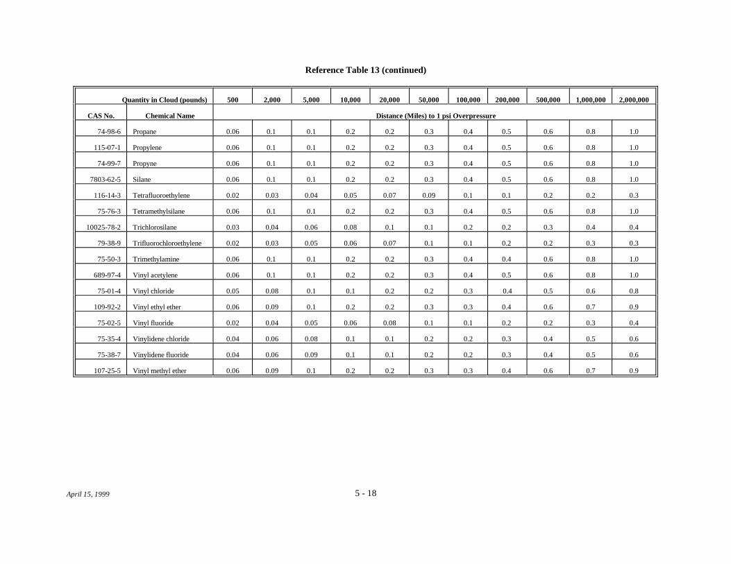
Reference Table 13 (continued)
Quantity in Cloud (pounds) 500 2,000 5,000 10,000 20,000 50,000 100,000 200,000 500,000 1,000,000 2,000,000
CAS No. Chemical Name Distance (Miles) to 1 psi Overpressure
5 - 18April 15, 1999
74-98-6 Propane 0.06 0.1 0.1 0.2 0.2 0.3 0.4 0.5 0.6 0.8 1.0
115-07-1 Propylene 0.06 0.1 0.1 0.2 0.2 0.3 0.4 0.5 0.6 0.8 1.0
74-99-7 Propyne 0.06 0.1 0.1 0.2 0.2 0.3 0.4 0.5 0.6 0.8 1.0
7803-62-5 Silane 0.06 0.1 0.1 0.2 0.2 0.3 0.4 0.5 0.6 0.8 1.0
116-14-3 Tetrafluoroethylene 0.02 0.03 0.04 0.05 0.07 0.09 0.1 0.1 0.2 0.2 0.3
75-76-3 Tetramethylsilane 0.06 0.1 0.1 0.2 0.2 0.3 0.4 0.5 0.6 0.8 1.0
10025-78-2 Trichlorosilane 0.03 0.04 0.06 0.08 0.1 0.1 0.2 0.2 0.3 0.4 0.4
79-38-9 Trifluorochloroethylene 0.02 0.03 0.05 0.06 0.07 0.1 0.1 0.2 0.2 0.3 0.3
75-50-3 Trimethylamine 0.06 0.1 0.1 0.2 0.2 0.3 0.4 0.4 0.6 0.8 1.0
689-97-4 Vinyl acetylene 0.06 0.1 0.1 0.2 0.2 0.3 0.4 0.5 0.6 0.8 1.0
75-01-4 Vinyl chloride 0.05 0.08 0.1 0.1 0.2 0.2 0.3 0.4 0.5 0.6 0.8
109-92-2 Vinyl ethyl ether 0.06 0.09 0.1 0.2 0.2 0.3 0.3 0.4 0.6 0.7 0.9
75-02-5 Vinyl fluoride 0.02 0.04 0.05 0.06 0.08 0.1 0.1 0.2 0.2 0.3 0.4
75-35-4 Vinylidene chloride 0.04 0.06 0.08 0.1 0.1 0.2 0.2 0.3 0.4 0.5 0.6
75-38-7 Vinylidene fluoride 0.04 0.06 0.09 0.1 0.1 0.2 0.2 0.3 0.4 0.5 0.6
107-25-5 Vinyl methyl ether 0.06 0.09 0.1 0.2 0.2 0.3 0.3 0.4 0.6 0.7 0.9

April 15, 1999
In Chapter 6
& Considerations for alternative release scenarios for regulated substances inProgram 2 or Program 3 processes.
& Potential alternative scenarios for releases of flammable substances.
6 DETERMINING ALTERNATIVE RELEASE SCENARIOS
You are required to analyze at least one alternative release scenario for each listed toxic substanceyou have in a Program 2 or Program 3 process above its threshold quantity. You also are required to analyzeone alternative release scenario for flammable substances in Program 2 or 3 processes as a class (i.e., youanalyze one scenario involving a flammable substance as a representative scenario for all the regulatedflammable substances you have on site in Program 2 or Program 3 processes). You do not need to analyze analternative scenario for each flammable substance. For example, if you have five listed substances – chlorine,ammonia, hydrogen chloride, propane, and acetylene – above the threshold in Program 2 or 3 processes, youwill need to analyze one alternative scenario each for chlorine, ammonia, and hydrogen chloride and a singlealternative scenario to cover propane and acetylene (listed flammable substances). Even if you have asubstance above the threshold in several processes or locations, you need only analyze one alternativescenario for it.
According to the rule (40 CFR 68.28), alternative scenarios should be more likely to occur than theworst-case scenario and should reach an endpoint offsite, unless no such scenario exists. Release scenariosconsidered should include, but are not limited to, the following:
& Transfer hose releases due to splits or sudden hose uncoupling;
& Process piping releases from failures at flanges, joints, welds, valves and valve seals, anddrains or bleeds;
& Process vessel or pump releases due to cracks, seal failure, or drain, bleed, or plug failure;
& Vessel overfilling and spill, or overpressurization and venting through relief valves orrupture disks; and
& Shipping container mishandling or puncturing leading to a spill.
Alternative release scenarios for toxic substances should be those that lead to concentrations abovethe toxic endpoint beyond your fenceline. Scenarios for flammable substances should have the potential tocause substantial damage, including on-site damage. Those releases that have the potential to reach thepublic are of the greatest concern. You should consider unusual situations, such as start-up and shut-down, inselecting an appropriate alternative scenario.
For alternative release scenarios, you are allowed to consider active mitigation systems, such asinterlocks, shutdown systems, pressure relieving devices, flares, emergency isolation systems, and fire waterand deluge systems, as well as passive mitigation systems, as described in Sections 3.1.2 and 3.2.3.
For alternative release scenarios for regulated substances used in ammonia refrigeration, chemicaldistribution, propane distribution, warehouses, or POTWs, consult EPA's risk management program guidance

Chapter 6Determining Alternative Release Scenarios
6 - 2April 15, 1999
documents for these industry sectors.
You have a number of options for selecting release scenarios for toxic or flammable substances.
& You may use your worst-case release scenario and apply your active mitigation system tolimit the quantity released and the duration of the release.
& You may use information from your process hazards analysis, if you have conducted one, toselect a scenario.
& You may review your accident history and choose an actual event as the basis of yourscenario.
& If you have not conducted a process hazards analysis, you may review your operations andidentify possible events and failures.
Whichever approach you select, the key information you need to define is the quantity to be releasedand the time over which it will be released; together, these allow you to estimate the release rate and useessentially the same methods you used for the worst-case analysis.
For flammable substances , the choice of alternative release scenarios is somewhat more complicatedthan for toxic substances, because the consequences of a release and the endpoint of concern may vary. Forthe flammable worst case, the consequence of concern is a vapor cloud explosion, with an overpressureendpoint. For alternative scenarios (e.g., fires), other endpoints (e.g., heat radiation) may need to beconsidered.
Possible scenarios involving flammable substances include:
& Vapor cloud fires (flash fires) may result from dispersion of a cloud of flammable vapor andignition of the cloud following dispersion. Such a fire could flash back and could represent asevere heat radiation hazard to anyone in the area of the cloud. This guidance providesmethods to estimate distances to a concentration equal to the lower flammability limit (LFL)for this type of fire. (See Sections 9.1, 9.2, and 10.1.)
& A pool fire, with potential radiant heat effects, may result from a spill of a flammable liquid. This guidance provides a simple method for estimating the distance from a pool fire to aradiant heat level that could cause second degree burns from a 40-second exposure. (SeeSection 10.2).
& A boiling liquid, expanding vapor explosion (BLEVE), leading to a fireball that mayproduce intense heat, may occur if a vessel containing flammable material rupturesexplosively as a result of exposure to fire. Heat radiation from the fireball is the primaryhazard; vessel fragments and overpressure from the explosion also can result. BLEVEs aregenerally considered unlikely events; however, if you think a BLEVE is possible at your site,this guidance provides a method to estimate the distance at which radiant heat effects mightlead to second degree burns. (See Section 10.3.) You also may want to consider models or

Chapter 6Determining Alternative Release Scenarios
6 - 3April 15, 1999
calculation methods to estimate effects of vessel fragmentation. (See Appendix A forreferences that may provide useful information for estimating such effects.)
& For a vapor cloud explosion to occur, rapid release of a large quantity, turbulent conditions(caused by a turbulent release or congested conditions in the area of the release, or both), andother factors are generally necessary. Vapor cloud explosions generally are consideredunlikely events; however, if conditions at your site are conducive to vapor cloud explosions,you may want to consider a vapor cloud explosion as an alternative scenario. This guidanceprovides methods you may use to estimate the distance to 1 psi overpressure for a vaporcloud detonation, based on less conservative assumptions than the worst-case analysis. (SeeSection 10.4.) A vapor cloud deflagration, involving lower flame speeds than a detonationand resulting in less damaging blast effects, is more likely than a detonation. This guidancedoes not provide methods for estimating the effects of a deflagration, but you may use othermethods of analysis if you want to consider such events. (See Appendix A for referencesthat may provide useful information.)
& A jet fire may result from the puncture or rupture of a tank or pipeline containing acompressed or liquefied gas under pressure. The gas discharging from the hole can form ajet that "blows" into the air in the direction of the hole; the jet then may ignite. Jet firescould contribute to BLEVEs and fireballs if they impinge on tanks of flammable substances. A large horizontal jet fire may have the potential to pose an offsite hazard. This guidancedoes not include a method for estimating consequence distances for jet fires. If you want toconsider a jet fire as an alternative scenario, you should consider other models or methodsfor the consequence analysis. (See Appendix A for references that may provide usefulinformation.)
If you carry out an alternative scenario analysis for a flammable mixture (i.e., a mixture that meetsthe criteria for NFPA 4), you need to consider all flammable components of the mixture, not just the regulatedflammable substance or substances in the mixture (see Section 5.2 on flammable mixtures). If the mixturecontains both flammable and non-flammable components, the analysis should be carried out considering onlythe flammable components.
Chapter 7 provides detailed information on calculating release rates for alternative release scenariosfor toxic substances. If you can estimate release rates for the toxic gases and liquids you have on site basedon readily available information, you may skip Chapter 7 and go to Chapter 8. Chapter 8 describes how toestimate distances to the toxic endpoint for alternative scenarios for toxic substances. Chapters 9 providesinformation on calculation release rates for flammable substances. Chapter 10 describes how to estimatedistances to flammable endpoints.

Chapter 6Determining Alternative Release Scenarios
6 - 4April 15, 1999
This page intentionally left blank.

April 15, 1999
In Section 7.1
& 7.1.1 Methods for unmitigated releases of toxic gases, including:
-- Release of toxic gas from a hole in a tank or pipe (for choked flowconditions, or maximum flow rate),
-- Release of toxic gas from a pipe, based on the flow rate through thepipe, or based on a hole in the pipe (using the same method as for ahole in a tank),
-- Puff releases (no method is provided; users are directed to use othermethods),
-- Gases liquefied under pressure, including gaseous releases from holesabove the liquid level in the tank and releases from holes in the liquidspace, and
-- Consideration of duration of releases of toxic gas.
& 7.1.2 Methods for adjusting the estimated release rate to account for active orpassive mitigation, including:
-- Active mitigation to reduce the release duration (e.g., automaticshutoff valves),
-- Active mitigation to reduce the release rate to air, and-- Passive mitigation (using the same method as for worst-case
scenarios).
7 ESTIMATION OF RELEASE RATES FOR ALTERNATIVESCENARIOS FOR TOXIC SUBSTANCES
For the alternative scenario analysis, you may use typical meteorological conditions and typicalambient temperature and humidity for your site. This guidance assumes D atmospheric stability and windspeed of 3.0 meters per second (6.7 miles per hour) as conditions likely to be applicable to many sites.
7.1 Release Rates for Toxic Gases
7.1.1 Unmitigated Releases of Toxic Gases
Gaseous Releases
Gaseous Release from Tank. Instead of assuming release of the entire contents of a vessel containinga toxic gas, you may decide to consider a more likely scenario as developed by the process hazards analysis,such as release from a hole in a vessel or pipe. To estimate a hole size you might assume, for example, thehole size that would result from shearing off a valve or pipe from a vessel containing a regulated substance. If you have a gas leak from a tank, you may use the following simplified equation to estimate a release ratebased on hole size, tank pressure, and the properties of the gas. This equation applies to choked flow, ormaximum gas flow rate. Choked flow generally would be expected for gases under pressure. (See AppendixD, Section D.6 for the derivation of this equation.)
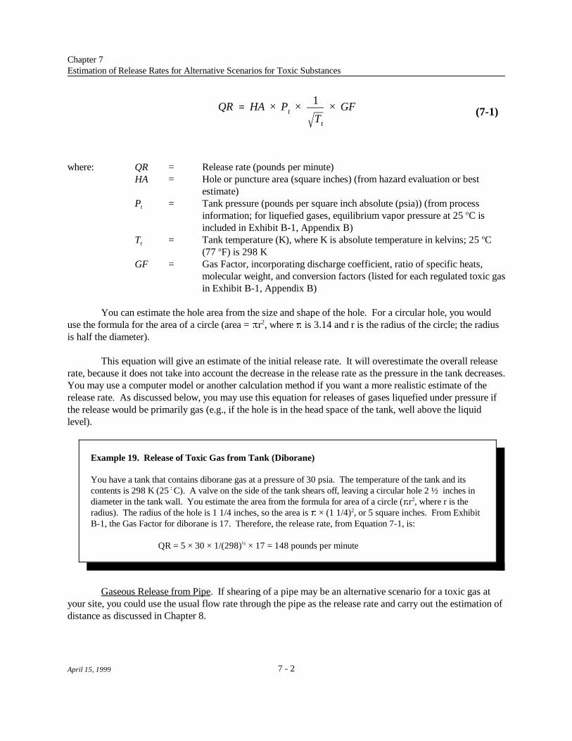
QR HA × Pt ×1
Tt
× GF
Chapter 7Estimation of Release Rates for Alternative Scenarios for Toxic Substances
7 - 2April 15, 1999
(7-1)
Example 19. Release of Toxic Gas from Tank (Diborane)
You have a tank that contains diborane gas at a pressure of 30 psia. The temperature of the tank and itscontents is 298 K (25(C). A valve on the side of the tank shears off, leaving a circular hole 2 ½ inches indiameter in the tank wall. You estimate the area from the formula for area of a circle (%r , where r is the2
radius). The radius of the hole is 1 1/4 inches, so the area is % × (1 1/4) , or 5 square inches. From Exhibit2
B-1, the Gas Factor for diborane is 17. Therefore, the release rate, from Equation 7-1, is:
QR = 5 × 30 × 1/(298) × 17 = 148 pounds per minute½
where: QR = Release rate (pounds per minute)HA = Hole or puncture area (square inches) (from hazard evaluation or best
estimate)P = Tank pressure (pounds per square inch absolute (psia)) (from processt
information; for liquefied gases, equilibrium vapor pressure at 25 C iso
included in Exhibit B-1, Appendix B)T = Tank temperature (K), where K is absolute temperature in kelvins; 25 Ct
o
(77 F) is 298 Ko
GF = Gas Factor, incorporating discharge coefficient, ratio of specific heats,molecular weight, and conversion factors (listed for each regulated toxic gasin Exhibit B-1, Appendix B)
You can estimate the hole area from the size and shape of the hole. For a circular hole, you woulduse the formula for the area of a circle (area = %r , where % is 3.14 and r is the radius of the circle; the radius2
is half the diameter).
This equation will give an estimate of the initial release rate. It will overestimate the overall releaserate, because it does not take into account the decrease in the release rate as the pressure in the tank decreases. You may use a computer model or another calculation method if you want a more realistic estimate of therelease rate. As discussed below, you may use this equation for releases of gases liquefied under pressure ifthe release would be primarily gas (e.g., if the hole is in the head space of the tank, well above the liquidlevel).
Gaseous Release from Pipe. If shearing of a pipe may be an alternative scenario for a toxic gas atyour site, you could use the usual flow rate through the pipe as the release rate and carry out the estimation ofdistance as discussed in Chapter 8.

QR HA × 6.8211.7
DF 2× LH �
669DF
× Pg
Chapter 7Estimation of Release Rates for Alternative Scenarios for Toxic Substances
7 - 3April 15, 1999
(7-2)
If you want to consider a release of toxic gas through a hole in a pipe as an alternative scenario, youmay use the method described above for a gas release from a hole in a tank. This method neglects the effectsof friction along the pipe and, therefore, provides a conservative estimate of the release rate.
Puff Releases. If a gaseous release from a hole in a tank or pipe is likely to be stopped very quickly(e.g., by a block valve), resulting in a puff of toxic gas that forms a vapor cloud rather than a plume, you maywant to consider other methods for determining a consequence distance. A cloud of toxic gas resulting from apuff release will not exhibit the same behavior as a plume resulting from a longer release (e.g., a release over10 minutes).
Liquefied Gases
Gases Liquefied Under Pressure. Gases liquefied under pressure may be released as gases, liquids,or a combination (two-phase), depending on a number of factors, including liquid level and the location of thehole relative to the liquid level. The resulting impact distances can vary greatly.
For releases from holes above the liquid level in a tank of gas liquefied under pressure, the releasecould be primarily gas, or the release may involve rapid vaporization of a fraction of the liquefied gas andpossibly aerosolization (two-phase release). It is complex to determine which type of release (i.e., gas, two-phase) will occur and the likely mix of gases and liquids in a two-phase release. The methods presented inthis guidance do not definitively address this situation. As a rule of thumb, if the head space is large and thedistance between the hole and the liquid level is relatively large given the height of the tank or vessel, youcould assume the release is gaseous and, therefore, use Equation 7-1 above. (Exhibit B-1, Appendix B,includes the equilibrium vapor pressure in psia for listed toxic gases liquefied under pressure at 25 C; thiso
pressure can be used in Equation 7-1.) However, use of this equation will not be conservative if the headspace is small and the release from the hole is two-phased. In situations where you are unsure of whether therelease would be gaseous or two-phase, you may want to consider other models or methods to carry out aconsequence analysis.
For a hole in the liquid space of a tank, you may use Equation 7-2 below to estimate the release rate. Exhibit B-1 in Appendix B gives the equilibrium vapor pressure in psia for listed toxic gases at 25 C; thiso
is the pressure required to liquefy the gas at this temperature. You can estimate the gauge pressure in thetank from the equilibrium vapor pressure by subtracting the pressure of the ambient atmosphere (14.7 psi). Exhibit B-1 also gives the Density Factor (DF) for each toxic gas at its boiling point. This factor can be usedto estimate the density of the liquefied gas (the density at 25 C would not be significantly different from theo
density at the boiling point for most of the listed gases). The equation to estimate the release rate is (seeAppendix D, Section D.7.1, for more information):

Chapter 7Estimation of Release Rates for Alternative Scenarios for Toxic Substances
7 - 4April 15, 1999
where: QR = Release rate (pounds per minute)HA = Hole or puncture area (square inches) (from hazard evaluation or best
estimate)DF = Density Factor (listed for each regulated toxic gas in Exhibit B-1, Appendix
B; 1/(DF x 0.033) is density in pounds per cubic foot) LH = Height of liquid column above hole (inches) (from hazard evaluation or best
estimate)P = Gauge pressure of the tank pressure (pounds per square inch gauge (psig),g
from vapor pressure of gas (listed in Exhibit B-1, Appendix B) minusatmospheric pressure (14.7 psi)
This equation gives the rate of release of liquid through the hole. For a gas liquefied under pressure, assumethat the released liquid will immediately flash into vapor (or a vapor/aerosol mixture) and the release rate toair is the same as the liquid release rate. This equation gives an estimate of the initial release rate. It willoverestimate the overall release rate, because it does not take into account the decrease in the release rate asthe pressure in the tank and the height of the liquid in the tank decrease. You may use a computer model oranother calculation method if you want a more realistic estimate of the release rate.
For a release from a broken pipe of a gas liquefied under pressure, see equations 7-4 to 7-6 below forliquid releases from pipes. Assume the released liquid flashes into vapor upon release and use the calculatedrelease rate as the release rate to air.
Gases Liquefied by Refrigeration. Gases liquefied by refrigeration alone may be treated as liquids. You may use the methods described in Section 7.2 for estimation of release rates.
Duration of Release
The duration of the release is used in choosing the appropriate generic reference table of distances, asdiscussed in Chapter 8. (You do not need to consider the duration of the release to use the chemical-specificreference tables.) You may calculate the maximum duration by dividing the quantity in the tank or thequantity that may be released from pipes by your calculated release rate. You may use 60 minutes as adefault value for maximum release duration. If you know, and can substantiate, how long it is likely to taketo stop the release, you may use that time as the release duration.
7.1.2 Mitigated Releases of Toxic Gases
For gases, passive mitigation may include enclosed spaces, as discussed in Section 3.1.2. Activemitigation for gases, which may be considered in analyzing alternative release scenarios, may include anassortment of techniques including automatic shutoff valves, rapid transfer systems (emergency deinventory),and water/chemical sprays. These mitigation techniques have the effect of reducing either the release rate orthe duration of the release, or both.

QRR (1 FR) × QR
Chapter 7Estimation of Release Rates for Alternative Scenarios for Toxic Substances
7 - 5April 15, 1999
(7-3)
Example 20. Water Spray Mitigation (Hydrogen Fluoride)
A bleeder valve on a hydrogen fluoride (HF) tank opens, releasing 660 pounds per minute of HF. Water spraysare applied almost immediately. Experimental field and laboratory test data indicate that HF vapors could bereduced by 90 percent. The reduced release rate is:
QR = (1 - 0.9) × (660 pounds per minute)R
= 66 pounds per minute
In estimating the consequence distance for this release scenario, you would need to consider the release bothbefore and after application of the water spray and determine which gives the greatest distance to the endpoint. You need to be able to substantiate the time needed to begin the water spray mitigation.
Active Mitigation
Active Mitigation to Reduce Release Duration. An example of a mitigation technique to reduce therelease duration is automatic shutoff valves. If you have an estimate of the rate at which the gas will bereleased and the time it will take to shut off the release, you may estimate the quantity potentially released(release rate times time). You must be able to substantiate the time it will take to shut off the release. If therelease will take place over a period of 10 minutes or more, you may use the release rate to estimate thedistance to the toxic endpoint, as discussed in Chapter 8. For releases stopped in less than 10 minutes,multiply the initial release rate by the duration of release to estimate the quantity released, then divide the newquantity by 10 minutes to estimate a mitigated release rate that you may apply to the reference tablesdescribed in Chapter 8 to estimate the consequence distance. If the release would be stopped very quickly,you might want to consider other methods that will estimate consequence distances for a puff release.
Active Mitigation to Directly Reduce Release Rate to Air. Examples of mitigation techniques todirectly reduce the release rate include scrubbers and flares. Use test data, manufacturer designspecifications, or past experience to determine the fractional reduction of the release rate by the mitigationtechnique. Apply this fraction to the release rate that would have occurred without the mitigation technique. The initial release rate, without mitigation, may be the release rate for the alternative scenario (e.g., a releaserate estimated from the equations presented earlier in this section) or the worst-case release rate. Themitigated release rate is:
where: QR = Reduced release rate (pounds per minute)R
FR = Fractional reduction resulting from mitigationQR = Release rate without mitigation (pounds per minute)

Chapter 7Estimation of Release Rates for Alternative Scenarios for Toxic Substances
7 - 6April 15, 1999
In Section 7.2
& 7.2.1 Methods for estimating the liquid release rate and quantity released fortoxic liquids released without mitigation, including:
-- Release of toxic liquid from a hole in a tank under atmosphericpressure (including toxic gases liquefied by refrigeration alone),
-- Release of toxic liquid from a hole in the liquid space of a pressurizedtank (the user is referred to equations provided in the section on toxicgases or in the technical appendix), and
-- Release of toxic liquid from a broken pipe.
& 7.2.2 Methods for estimating the liquid release rate and quantity released fortoxic liquids released with mitigation measures that reduce the duration of theliquid release or the quantity of liquid released (e.g., automatic shutoff valves),
& 7.2.3 Methods for estimating the evaporation rate of toxic liquids from pools,accounting for:
-- Ambient temperature,-- Elevated temperature, -- Diked areas,-- Releases into buildings,-- Active mitigation to reduce the evaporation rate of the liquid, -- Temperatures between 25 C and 50 C, and o o
-- Duration of the release.
& 7.2.4 Methods for estimating the evaporation rate for common water solutionsof regulated toxic substances and for oleum.
Passive Mitigation
The same simplified method used for worst-case releases may be used for alternative releasescenarios to estimate the release rate to the outside air from a release in an enclosed space. For alternativescenarios, you may use a modified release quantity, if appropriate. You may also adjust the mitigation factorto account for the effects of ventilation, if appropriate for the alternative scenario you have chosen. Use theequations presented in Section 3.1.2 to estimate the release rate to the outside air.
Duration of Release
You should estimate the duration of the release either from your knowledge of the length of time itmay take to stop the release (be prepared to substantiate your time estimate) or by dividing the quantity thatmay be released by your estimated release rate. (You do not need to consider the release duration to use thechemical-specific reference tables of distances.)
7.2 Release Rates for Toxic Liquids

QRL HA × LH × LLF
Chapter 7Estimation of Release Rates for Alternative Scenarios for Toxic Substances
7 - 7April 15, 1999
(7-4)
This section describes methods for estimating liquid release rates from tanks and pipes. The releasedliquid is assumed to form a pool, and the evaporation rate from the pool is estimated as for the worst-casescenario. For the alternative scenario, you may assume the average wind speed in your area in the calculationof evaporation rate, instead of the worst-case wind speed of 1.5 meters per second (3.4 miles per hour). Forthe reference tables in this guidance, the wind speed for alternative scenarios is assumed to be 3.0 meters persecond (6.7 miles per hour).
If you have sufficient information to estimate the quantity of liquid that might be released to anundiked area under an alternative scenario, you may go directly to Section 7.2.3 to estimate the evaporationrate from the pool and the release duration. After you have estimated the evaporation rate and releaseduration, go to Chapter 8 for instructions on estimating distance to the toxic endpoint.
7.2.1 Liquid Release Rate and Quantity Released for Unmitigated Releases
Release from Tank
Tank under Atmospheric Pressure. If you have a liquid stored in a tank at atmospheric pressure(including gases liquefied by refrigeration alone), you may use the following simple equation to estimate theliquid release rate from a hole in the tank below the liquid level. (See Appendix D, Section D.7.1, for thederivation of this equation.)
where: QR = Liquid release rate (pounds per minute)L
HA = Hole or puncture area (square inches) (from hazard evaluation or bestestimate)
LH = Height of liquid column above hole (inches) (from hazard evaluation or bestestimate)
LLF = Liquid Leak Factor incorporating discharge coefficient and liquid density(listed for each toxic liquid in Exhibit B-2, Appendix B).
Remember that this equation only applies to liquids in tanks under atmospheric pressure. Thisequation will give an overestimate of the release rate, because it does not take into account the decrease in therelease rate as the height of the liquid above the hole decreases. You may use a computer model or anothercalculation method if you want a more realistic estimate of the liquid release rate.
You may estimate the quantity that might be released by multiplying the liquid release rate from theabove equation by the time (in minutes) that likely would be needed to stop the release. You should be ableto substantiate the time needed to stop the release. Alternatively, you may assume the release would stopwhen the level of liquid in the tank drops to the level of the hole. You may estimate the quantity of liquidabove that level in the tank from the dimensions of the tank, the liquid level at the start of the leak, and thelevel of the hole. Assume the estimated quantity is released into a pool and use the method and equations inSection 7.2.3 below to determine the evaporation rate of the liquid from the pool and the duration of therelease. As discussed in Section 7.2.3, if you find that your estimated evaporation rate is greater thanestimated liquid release rate, you should use the liquid release rate as the release rate to air.

Va FR × DF × 0.033
Ap
Chapter 7Estimation of Release Rates for Alternative Scenarios for Toxic Substances
7 - 8April 15, 1999
Example 21. Liquid Release from Atmospheric Tank (Allyl Alcohol)
You have a tank that contains 20,000 pounds of allyl alcohol at ambient temperature and pressure. A valve onthe side of the tank shears, leaving a hole in the tank wall 5 square inches in area. The liquid column is 23inches above the hole in the tank. From Exhibit B-2, the Liquid Leak Factor for allyl alcohol is 41. Therefore,from Equation 7-4, the liquid release rate is:
QR = 5 × (23) × 41 = 983 pounds per minuteL½
It takes 10 minutes to stop the release, so 10 minutes × 983 pounds per minute = 9,830 pounds of allyl alcoholreleased.
(7-5)
Pressurized Tank. If you have a liquid stored in a tank under pressure, you may estimate a releaserate for liquid from a hole in the liquid space of the tank using the equation presented above for gasesliquefied under pressure (Equation 7-2 in Section 7.1.1) or the equations in Appendix D, Section D.7.1.
Release from Pipe
If you have a liquid flowing through a pipe at approximately atmospheric pressure, and the pipelineremains at about the same height between the pipe inlet and the pipe break, you can estimate the quantity ofliquid released from the flow rate in the pipe and the time it would take to stop the release by multiplying theflow rate by the time. For liquids at atmospheric pressure, assume the liquid is spilled into a pool and use themethods in Section 7.2.3 below to estimate the release rate to air.
For the release of a liquid under pressure from a long pipeline, you may use the equations below (seeAppendix D, Section D.7.2 for more information on these equations). These equations apply both tosubstances that are liquid at ambient conditions and to gases liquefied under pressure. This method does notconsider the effects of friction in the pipe. First estimate the initial operational flow velocity of the substancethrough the pipe using the initial operational flow rate as follows:
where: V = Initial operational flow velocity (feet per minute)a
FR = Initial operational flow rate (pounds per minute)DF = Density Factor (from Exhibit B-2, Appendix B)A = Cross-sectional area of pipe (square feet)p
You can estimate the cross-sectional area of the pipe from the diameter or radius (half the diameterof the pipe) using the formula for the area of a circle (area = %r , where r is the radius). 2
The release velocity is then calculated based on the initial operational flow, any gravitational

Vb 197 × [28.4 × (PT 14.7) × DF] � [5.97 × (Za Zb)] � [2.58×10⁵ × Va2]
QRL
Vb × Ap
DF × 0.033
Chapter 7Estimation of Release Rates for Alternative Scenarios for Toxic Substances
7 - 9April 15, 1999
(7-6)
(7-7)
acceleration or deceleration effects resulting from changes in the height of the pipeline, and the pressuredifference between the pressure in the pipe and atmospheric pressure, using a form of the Bernoulli equation:
where: V = Release velocity (feet per minute)b
P = Total pressure on liquid in pipe (psia)T
DF = Density factor, see Exhibit B-1 or Exhibit B-2Z = Height of pipeline at inlet (feet)a
Z = Height of pipeline at break (feet)b
V = Operational velocity (feet per minute), calculated from Equation 7-5a
Please note that if the height of the pipe at the release point is higher than the initial pipe height, then Z -Z isa b
negative, and the height term will cause the estimated release velocity to decrease.
The release velocity can then be used to calculate a release rate as follows:
where: QR = Release rate (pounds per minute)L
V = Release velocity (feet per minute)b
DF = Density FactorA = Cross-sectional area of pipe (square feet)p
You may estimate the quantity released into a pool from the broken pipe by multiplying the liquidrelease rate (QR ) from the equation above by the time (in minutes) that likely would be needed to stop theL
release (or to empty the pipeline). Assume the estimated quantity is released into a pool and use the methodand equations described in Section 7.2.3 below to determine the evaporation rate of the liquid from the pool. You must be able to substantiate the time needed to stop the release.
As noted above in Section 7.1.1, for a release from a pipe of gas liquefied under pressure, assumethat the released liquid is immediately vaporized, and use the calculated liquid release rate as the release rateto air. If the release duration would be very short (e.g., because of active mitigation measures), determine thetotal quantity of the release as the release rate times the duration, then estimate a new release rate as thequantity divided by 10. This will give you a release rate that you can use with the 10-minute reference tablesof distances in this guidance to estimate a distance to the endpoint.
In the case of very long pipes, release rates from a shear or hole will be lower than the estimates fromthis method because of pipe roughness and frictional head loss. If friction effects are deemed considerable, anestablished method for calculating frictional head loss such as the Darcy formula may be used.

Chapter 7Estimation of Release Rates for Alternative Scenarios for Toxic Substances
7 - 10April 15, 1999
Example 22. Mitigated Liquid Release
A bromine injection system suffers a hose failure; the greatly lowered system pressure triggers an automaticshutoff valve within 30 seconds of the release. The flow rate out of the ruptured hose is approximately 330pounds per minute. Because the release occurred for only 30 seconds (0.5 minutes), the total quantity spilledwas 330 x 0.5, or 165 pounds.
7.2.2 Liquid Release Rate and Quantity Released for Mitigated Releases
For alternative release scenarios, you are permitted to take credit for both passive and activemitigation systems, or a combination if both are in place. Active mitigation techniques that reduce the rate ofliquid release or the quantity released into the pool are discussed in this section. Active and passivemitigation to reduce the evaporation rate of liquid from a pool are discussed in the next section.
Active Mitigation to Reduce Quantity Released
Examples of mitigation techniques to reduce the quantity released into the pool include automaticshutoff valves and emergency deinventory. You may use the equations in Section 7.2.1 above for calculatingliquid release rate, if applicable. Estimate the approximate time needed to stop the release by the mitigationtechnique (you must be able to justify your estimate). Multiply the release rate times the duration of releaseto estimate quantity released. Assume the estimated quantity is released into a pool and use the method andequations described in Section 7.2.3 below to determine the evaporation rate of the liquid from the pool. Youshould also consider mitigation (active or passive) of evaporation from the pool, if applicable, as discussed inSection 7.2.3 below.
7.2.3 Evaporation Rate from Liquid Pool
After you have estimated the quantity of liquid released, assume that the liquid forms a pool andcalculate the evaporation rate from the pool as described below. You may account for both passive and activemitigation in estimating the release rate. Passive mitigation may include techniques already discussed inSection 3.2.3 such as dikes and trenches. Active mitigation to reduce the release rate of liquid in pools to theair may include an assortment of techniques including foam or tarp coverings and water or chemical sprays. Some methods of accounting for passive and active mitigation are discussed below.
If the calculated evaporation rate from the pool is greater than the liquid release rate you haveestimated from the container, no pool would be formed, and calculating the release rate as the evaporationrate from a pool would not be appropriate. If the pool evaporation rate is greater than the liquid release rate,use the liquid release rate as the release rate to air. Consider this possibility particularly for relatively volatileliquids, gases liquefied by refrigeration, or liquids at elevated temperature that form pools with no mitigation.

QR QS × 2.4 × LFA × DF
QR QS × 2.4 × LFB × DF
Chapter 7Estimation of Release Rates for Alternative Scenarios for Toxic Substances
7 - 11April 15, 1999
(7-8)
Example 23. Evaporation from Pool Formed by Liquid Released from Hole in Tank (Allyl Alcohol)
In Example 21, 9,830 pounds of allyl alcohol were estimated to be released from a hole in a tank. From ExhibitB-2, the Density Factor for allyl alcohol is 0.58, and the Liquid Factor Ambient is 0.0046. Assuming that theliquid is not released into a diked area or inside a building, the evaporation rate from the pool of allyl alcohol,from Equation 7-8, is:
QR = 9,830 × 2.4 × 0.0046 × 0.58 = 63 pounds per minute
(7-9)
Unmitigated
Ambient temperature. For pools with no mitigation, if the liquid is always at ambient temperature,find the Liquid Factor Ambient (LFA) and the Density Factor (DF) in Exhibit B-2 of Appendix B (seeAppendix D, Section D.2.2 for the derivation of these factors). If your ambient temperature is between 25 Co
and 50 C, you may use this method to calculate the release rate, and then use the appropriate Temperatureo
Correction Factor from Exhibit B-4, Appendix B, to adjust the release rate, as described below. For gasesliquefied by refrigeration, use the Liquid Factor Boiling (LFB) and DF from Exhibit B-1. Calculate therelease rate from the following equation for liquids at ambient temperature with no mitigation:
where: QR = Release rate (pounds per minute)QS = Quantity released (pounds)2.4 = Wind speed factor = 3.0 , where 3.0 meters per second (6.7 miles per0.78
hour) is the wind speed for the alternative scenario for purposes of thisguidance
LFA = Liquid Factor AmbientDF = Density Factor
This method assumes that the total quantity of liquid released spreads out to form a pool onecentimeter in depth; it does not take into account evaporation as the liquid is released.
Elevated temperature. For pools with no mitigation, if the liquid is at an elevated temperature (above50 C or at or close to its boiling point), find the Liquid Factor Boiling (LFB) and the Density Factor (DF) ino
Exhibit B-2 of Appendix B (see Appendix D, Section D.2.2, for the derivation of these factors). For liquidsat temperatures between 25 C and 50 C, you may use the method above for ambient temperature and applyo o
the appropriate Temperature Correction Factor from Appendix B, Exhibit B-4, to the result, as discussedbelow. For liquids above 50 C, or close to their boiling points, or with no Temperature Correction Factorso
available, calculate the release rate of the liquid from the following equation:

QR 2.4 × LFA × A
QR 2.4 × LFB × A
Chapter 7Estimation of Release Rates for Alternative Scenarios for Toxic Substances
7 - 12April 15, 1999
(7-10)
(7-11)
where: QR = Release rate (pounds per minute)QS = Quantity released (pounds)2.4 = Wind speed factor = 3.0 , where 3.0 meters per second (6.7 miles per0.78
hour) is the wind speed for the alternative scenario for purposes of thisguidance
LFB = Liquid Factor BoilingDF = Density Factor
Mitigated
Diked Areas. If the toxic liquid will be released into an area where it will be contained by dikes,compare the diked area to the maximum area of the pool that could be formed, as described in Section 3.2.3(see Equation 3-6). Also verify that the quantity spilled will be totally contained by the dikes. The smaller ofthe two areas should be used in determination of the evaporation rate. If the maximum area of the pool issmaller than the diked area, calculate the release rate as described for pools with no mitigation (above). If thediked area is smaller, and the spill will be totally contained, go to Exhibit B-2 in Appendix B to find theLiquid Factor Ambient (LFA), if the liquid is at ambient temperature, or the Liquid Factor Boiling (LFB), ifthe liquid is at an elevated temperature. For temperatures between 25 C and 50 C, you may use theo o
appropriate Temperature Correction Factor from Exhibit B-4, Appendix B, to adjust the release rate, asdescribed below. For gases liquefied by refrigeration, use the LFB. Calculate the release rate from the dikedarea as follows for liquids at ambient temperature:
or, for liquids at elevated temperatures or gases liquefied by refrigeration alone:
where: QR = Release rate (pounds per minute)2.4 = Wind speed factor = 3.0 , where 3.0 meters per second (6.7 miles per0.78
hour) is the wind speed for the alternative scenario for purposes of thisguidance
LFA = Liquid Factor Ambient (listed in Exhibit B-2, Appendix B)LFB = Liquid Factor Boiling (listed in Exhibit B-1 or B-2, Appendix B)A = Diked area (square feet)
Releases Into Buildings. If a toxic liquid is released inside a building, compare the area of thebuilding floor or any diked area that would contain the spill to the maximum area of the pool that could beformed; the smaller of the two areas should be used in determining the evaporation rate, as for the worst-casescenario. The maximum area of the pool is determined from Equation 3-6 in Section 3.2.3 for releases intodiked areas. The area of the building floor is the length times width of the floor (in feet) (Equation 3-9).
If the floor area or diked area is smaller than the maximum pool size, estimate the outdoorevaporation rate from a pool the size of the floor area or diked area from Equation 7-10. If the maximumpool area is smaller, estimate the outdoor evaporation rate from a pool of maximum size from Equation 7-8.

QRRV (1FR) × QR
Chapter 7Estimation of Release Rates for Alternative Scenarios for Toxic Substances
7 - 13April 15, 1999
(7-12)
Estimate the rate of release of the toxic vapor from the building as five percent of the calculated outdoorevaporation rate (multiply your evaporation rate by 0.05). See Appendix D, Section D.2.4 for moreinformation on releases into buildings.
Active Mitigation to Reduce Evaporation Rate. Examples of active mitigation techniques to reducethe evaporation rate from the pool include water sprays and foam or tarp covering. Use test data,manufacturer design specifications, or past experience to determine the fractional reduction of the release rateby the mitigation technique. Apply this fraction to the release rate (evaporation rate from the pool) thatwould have occurred without the mitigation technique, as follows:
where: QR = Reduced evaporation rate (release rate to air) from pool (pounds perRV
minute)FR = Fractional reduction resulting from mitigationQR = Evaporation rate from pool without mitigation (pounds per minute)
Temperature Corrections for Liquids at Temperatures between 25 and 50 C o
If your liquid is at a temperature between 25 C (77 F) and 50 C (122 F), you may use theo o o o
appropriate Temperature Correction Factor (TCF) from Exhibit B-4, Appendix B, to calculate a correctedrelease rate. Calculate the release rate (QR) of the liquid at 25 C (77 F) as described above for unmitigatedo o
releases or releases in diked areas and multiply the release rate by the appropriate TCF as described inSection 3.2.5.
Evaporation Rate Compared to Liquid Release Rate
If you estimated the quantity of liquid in the pool based on an estimated liquid release rate from ahole in a container or pipe, as discussed in Sections 7.2.1 and 7.2.2, compare the evaporation rate with theliquid release rate. If the evaporation rate from the pool is greater than the liquid release rate, use the liquidrelease rate as the release rate to air.
Duration of Release
After you have estimated a release rate as described above, determine the duration of the vaporrelease from the pool (the time it will take for the liquid pool to evaporate completely). To estimate the timein minutes, divide the total quantity released (in pounds) by the release rate (in pounds per minute) (seeEquation 3-5 in Section 3.2.2). If you are using the liquid release rate as the release rate to air, as discussedin the preceding paragraph, estimate a liquid release duration as discussed in Section 7.2.1 or 7.2.2. Theduration could be the time it would take to stop the release or the time it would take to empty the tank or torelease all the liquid above the level of the leak. If you have corrected the release rate for a temperaturesabove 25 C, use the corrected release rate to estimate the duration.o

Chapter 7Estimation of Release Rates for Alternative Scenarios for Toxic Substances
7 - 14April 15, 1999
7.2.4 Common Water Solutions and Oleum
You may use the methods described above in Sections 7.2.1, 7.2.2, and 7.2.3 for pure liquids toestimate the quantity of a solution of a toxic substance or oleum that may be spilled into a pool. LFA, DF,and LLF values for several concentrations of ammonia, formaldehyde, hydrochloric acid, hydrofluoric acid,and nitric acid in water solution and for oleum are listed in Appendix B, Exhibit B-3. The LFA for a windspeed of 3.0 meters per second (6.7 miles per hour) should be used in the release rate calculations foralternative scenarios for pools of solutions at ambient temperature.
For unmitigated releases or releases with passive mitigation, follow the instructions in Section 7.2.3. If active mitigation measures are in place, you may estimate a reduced release rate from the instructions onactive mitigation in Section 7.2.2. Use the total quantity of the solution as the quantity released from thevessel or pipeline (QS) in carrying out the calculation of the release rate to the atmosphere.
If the solution is at an elevated temperature, see Section 3.3. As discussed in Section 3.3, you maytreat the release of the substance in solution as a release of the pure substance. Alternatively, if you havevapor pressure data for the solution at the release temperature, you may estimate the release rate from theequations in Appendix D, Sections D.2.1 and D.2.2.
If you estimated the quantity of solution in the pool based on an estimated liquid release rate from ahole in a container or pipe, as discussed in Sections 7.2.1 and 7.2.2, compare the evaporation rate with theliquid release rate. If the evaporation rate from the pool is greater than the liquid release rate, use the liquidrelease rate as the release rate to air.

April 15, 1999
In Chapter 8
& Reference tables of distances for alternative releases, including:
-- Generic reference tables (Exhibit 4), and-- Chemical-specific reference tables (Exhibit 5).
& Considerations include:
-- Gas density (neutrally buoyant or dense),-- Duration of release (10 minutes or 60 minutes),-- Topography (rural or urban).
8 ESTIMATION OF DISTANCE TO THE ENDPOINT FORALTERNATIVE SCENARIOS FOR TOXIC SUBSTANCES
For estimating consequence distances for alternative scenarios for toxic substances, this guidanceprovides four generic reference tables for neutrally buoyant gases and vapors and four for dense gases. Thegeneric reference tables of distances (Reference Tables 14-21) are found at the end of Chapter 10. Thegeneric tables and the conditions for which each table is applicable are described in Exhibit 4. Four chemical-specific tables also are provided for ammonia, chlorine, and sulfur dioxide. The chemical-specific referencetables follow the generic reference tables at the end of Chapter 10. These tables, and the applicableconditions, are described in Exhibit 5.
All the reference tables of distances for alternative scenarios were developed assuming D stabilityand a wind speed of 3.0 meters per second (6.7 miles per hour) as representative of likely conditions for manysites. Many wind speed and atmospheric stability combinations may be possible at different times indifferent parts of the country. If D stability and 3.0 meters per second are not reasonable conditions for yoursite, you may want to use other methods to estimate distances.
For simplicity, this guidance assumes ground level releases. This guidance, therefore, mayoverestimate the consequence distance if your alternative scenario involves a release above ground level,particularly for neutrally buoyant gases and vapors. If you want to assume an elevated release, you may wantto consider other methods to determine the consequence distance.
The generic reference tables should be used for all toxic substances other than ammonia, chlorine,and sulfur dioxide. To use the generic reference tables, you need to consider the release rates estimated forgases and evaporation from liquid pools and the duration of the release. For the alternative scenarios, theduration of toxic gas releases may be longer than the 10 minutes assumed for the worst-case analysis forgases. You need to determine the appropriate toxic endpoint and whether the gas or vapor is neutrallybuoyant or dense, using the tables in Appendix B and considering the conditions of the release. You mayinterpolate between entries in the reference tables.

Chapter 8Estimation of Distance to the Endpoint for Alternative Scenarios for Toxic Substances
8 - 2April 15, 1999
Exhibit 4Generic Reference Tables of Distances for Alternative Scenarios
Applicable Conditions Reference TableNumber
Gas or Vapor Density Topography Release Duration(minutes)
Neutrally buoyant Rural 10 14
60 15
Urban 10 16
60 17
Dense Rural 10 18
60 19
Urban 10 20
60 21
Exhibit 5Chemical-Specific Reference Tables of Distances for Alternative Scenarios
Substance TableConditions of Release Reference
NumberGas or Vapor Release Duration TopographyDensity (minutes)
Anhydrous ammonia Dense 10-60 Rural, urban 22liquefied under pressure
Non-liquefied ammonia, Neutrally buoyant 10-60 Rural, urban 23ammonia liquefied byrefrigeration, or aqueousammonia
Chlorine Dense 10-60 Rural, urban 24
Sulfur dioxide (anhydrous) Dense 10-60 Rural, urban 25

Chapter 8Estimation of Distance to the Endpoint for Alternative Scenarios for Toxic Substances
8 - 3April 15, 1999
Note the following concerning the use of the chemical-specific reference tables for ammonia,chlorine, and sulfur dioxide:
& The table for anhydrous ammonia (Reference Table 22) applies only to flashing releases ofammonia liquefied under pressure. Use Table 23 for release of ammonia as a gas (e.g.,evaporation from a pool or release from the vapor space of a tank).
& You may use these tables for releases of any duration.
To use the reference tables of distances, follow these steps:
For Regulated Toxic Substances Other than Ammonia, Chlorine, and Sulfur Dioxide
& Find the toxic endpoint for the substance in Appendix B (Exhibit B-1 for toxic gases orExhibit B-2 for toxic liquids).
& Determine whether the table for neutrally buoyant or dense gases and vapors is appropriatefrom Appendix B (Exhibit B-1 for toxic gases or Exhibit B-2, column for alternative case,for toxic liquids). A toxic gas that is lighter than air may behave as a dense gas upon releaseif it is liquefied under pressure, because the released gas may be mixed with liquid droplets,or if it is cold. Consider the state of the released gas when you decide which table isappropriate.
& Determine whether the table for rural or urban conditions is appropriate.
-- Use the rural table if your site is in an open area with few obstructions.
-- Use the urban table if your site is in an urban or obstructed area.
& Determine whether the 10-minute table or the 60-minute table is appropriate.
-- Use the 10-minute table for releases from evaporating pools of common watersolutions and of oleum.
-- If you estimated the release duration for gas release or pool evaporation to be 10minutes or less, use the 10-minute table.
-- If you estimated the release duration for gas release or pool evaporation to be morethan 10 minutes, use the 60-minute table.
Neutrally Buoyant Gases or Vapors
& If Exhibit B-1 or B-2 indicates the gas or vapor should be considered neutrally buoyant, andother factors would not cause the gas or vapor to behave as a dense gas, divide the estimatedrelease rate (pounds per minute) by the toxic endpoint (milligrams per liter).

Chapter 8Estimation of Distance to the Endpoint for Alternative Scenarios for Toxic Substances
8 - 4April 15, 1999
& Find the range of release rate/toxic endpoint values that includes your calculated releaserate/toxic endpoint in the first column of the appropriate table (Reference Table 14, 15, 16,or 17), then find the corresponding distance to the right.
Dense Gases or Vapors
& If Exhibit B-1 or B-2 or consideration of other relevant factors indicates the substanceshould be considered a dense gas or vapor (heavier than air), find the distance in theappropriate table (Reference Table 18, 19, 20, or 21) as follows;
-- Find the toxic endpoint closest to that of the substance by reading across the top ofthe table. If the endpoint of the substance is halfway between two values on thetable, choose the value on the table that is smaller (to the left). Otherwise, choosethe closest value to the right or the left.
-- Find the release rate closest to the release rate estimated for the substance at the leftof the table. If the calculated release rate is halfway between two values on thetable, choose the release rate that is larger (farther down on the table). Otherwise,choose the closest value (up or down on the table).
-- Read across from the release rate and down from the endpoint to find the distancecorresponding to the toxic endpoint and release rate for your substance.
For Ammonia, Chlorine, or Sulfur Dioxide
& Find the appropriate chemical-specific table for your substance (see the descriptions ofReference Tables 22-25 in Exhibit 5).
-- If you have ammonia liquefied by refrigeration alone, you may use Reference Table23, even if the duration of the release is greater than 10 minutes.
-- If you have chlorine or sulfur dioxide liquefied by refrigeration alone, you may usethe chemical-specific reference tables, even if the duration of the release is greaterthan 10 minutes.
& Determine whether rural or urban topography is applicable to your site.
-- Use the rural column in the reference table if your site is in an open area with fewobstructions.
-- Use the urban column if your site is in an urban or obstructed area.
& Estimate the consequence distance as follows:
-- In the left-hand column of the table, find the release rate closest to your calculatedrelease rate.

Chapter 8Estimation of Distance to the Endpoint for Alternative Scenarios for Toxic Substances
8 - 5April 15, 1999
Example 24. Gas Release of Chlorine
Assume that you calculated a release rate of 500 pounds per minute of chlorine from a tank. A chemical-specific table is provided for chlorine, so you do not need to consult Appendix B for information on chlorine. The topography of your site is urban. For a release of chlorine under average meteorology (D stability and 3meters per second wind speed), go to Reference Table 24. The estimated release rate of 500 pounds perminute, with urban topography, corresponds to a consequence distance of 0.4 miles.
Additional Modeling for Comparison
The ALOHA model gave a distance of 3.0 miles to the endpoint, using the same assumptions.
The WHAZAN model gave a distance of 3.2 miles to the endpoint, using the same assumptions and the densecloud dispersion model.
-- Read the corresponding distance from the appropriate column (urban or rural) to theright.
The development of the generic reference tables is discussed in Appendix D, Sections D.4.1 andD.4.2. The development of the chemical-specific reference tables is discussed in industry-specific riskmanagement program guidance documents and a backup information document that are cited in SectionD.4.3. If you think the results of the method presented here overstate the potential consequences of a youralternative release scenario, you may choose to use other methods or models that take additional site-specificfactors into account.
Examples 24 and 25 below include the results of modeling using two other models, ALOHA andWHAZAN, for comparison with the results of the methods presented in this guidance. Appendix D, SectionD.4.5 provides additional information on this modeling.

Chapter 8Estimation of Distance to the Endpoint for Alternative Scenarios for Toxic Substances
8 - 6April 15, 1999
Example 25. Allyl Alcohol Evaporating from Pool
In Example 23, the evaporation rate of allyl alcohol from a pool was calculated as 63 pounds per minute. The totalquantity in the pool was estimated as 9,830 pounds; therefore, the pool would evaporate in 9,830/63 or 156minutes. You would use a 60-minute reference table to estimate the distance to the endpoint. From Exhibit B-2 inAppendix B, the toxic endpoint for allyl alcohol is 0.036 mg/L, and the appropriate reference table for thealternative scenario analysis is a neutrally buoyant plume table. To find the distance from the neutrally buoyantplume tables, you need the release rate divided by the endpoint. In this case, it is 63/0.036, or 1,750. Assumingthe release takes place in a rural location, you use Reference Table 15, applicable to neutrally buoyant plumes, 60-minute releases, and rural conditions. From this table, you estimate the distance as 0.4 mile.
Additional Modeling for Comparison
The ALOHA model gave a distance of 0.7 mile to the endpoint for a release rate of 63 pounds per minute, usingthe same assumptions and the dense gas model.
The WHAZAN model gave a distance of 0.5 mile to the endpoint for a release rate of 63 pounds per minute, usingthe same assumptions and the buoyant plume dispersion model.

April 15, 1999
In Chapter 9
& Methods to estimate a release rate to air for a flammable gas (9.1) or liquid(9.2).
Example 26. Release Rate of Flammable Gas from Hole in Tank (Ethylene)
A pipe tears off a tank containing ethylene. The pipe is in the vapor space of the tank. The release rate fromthe hole can be estimated from Equation 7-1 in Section 7.1. You estimate that the pipe would leave a hole withan area (HA) of 5 square inches. The temperature inside the tank (T , absolute temperature, Kelvin) is 282 K,t
9(C, and the square root of the temperature is 16.8. The pressure in the tank (P ) is approximately 728 poundst
per square inch absolute (psia). From Exhibit C-2, Appendix C, the gas factor (GF) for ethylene is 18. FromEquation 7-1, the release rate (QR) is:
QR = 5 × 728 × (1/16.8) × 18 = 3,900 pounds per minute
9 ESTIMATION OF RELEASE RATES FOR ALTERNATIVESCENARIOS FOR FLAMMABLE SUBSTANCES
9.1 Flammable Gases
Gaseous Release from Tank or Pipe
An alternative scenario for a release of a flammable gas may involve a leak from a vessel or piping. To estimate a release rate for flammable gases from hole size and storage conditions, you may use the methoddescribed above in Section 7.1.1 for toxic gases. This release rate may be used to determine the dispersiondistance to the lower flammability limit (LFL), as described in Section 10.1. Exhibit C-2 in Appendix Cincludes Gas Factors (GF) that may be used in carrying out the calculations for each of the regulatedflammable gases.
Gases Liquefied Under Pressure
A vapor cloud fire is a possible result of a release of a gas liquefied under pressure. You may use themethods described in Section 7.1.1 for toxic gases liquefied under pressure to estimate the release rate from ahole in a tank for a flammable gas liquefied under pressure. The estimated release rate may be used toestimate the dispersion distance to the LFL for a vapor cloud fire.
Flammable gases that are liquefied under pressure may be released very rapidly, with partialvaporization of the liquefied gas and possible aerosol formation. Section 10.4 presents a method forestimating the consequences of a vapor cloud explosion from such a release of a gas liquefied under pressure.

Chapter 9Estimation of Release Rates for Alternative Scenarios for Flammable Substances
9 - 2April 15, 1999
Gases Liquefied by Refrigeration
Flammable gases liquefied by refrigeration alone can be treated as liquids for the alternative scenarioanalysis, as discussed in Section 9.2 and Section 10.2, below.
9.2 Flammable Liquids
You may estimate a release rate for flammable liquids by estimating the evaporation rate from apool. Release rates also can be estimated for flammable gases liquefied by refrigeration alone by this method,if the liquefied gas is likely to form a pool upon release. You first need to estimate the quantity in the pool.
You may use the method discussed in Section 7.2.1 to estimate a rate of liquid release for flammableliquids into a pool from a hole in a tank or from a pipe shear. Exhibit C-3 in Appendix C includes liquid leakfactors (LLF) for calculating release rate from a hole. Note that the LLF is appropriate only for atmospherictanks. LLF values are not provided for liquefied flammable gases; you will need to estimate the quantity inthe pool from other information for liquefied flammable gases.
Once you have an estimate of the quantity of flammable liquid in a pool, you may use the methodspresented in Section 7.2.3 to estimate the evaporation rate from the pool. Liquid factors at ambient andboiling temperature (LFA and LFB) for liquids for the calculation are listed in Exhibit C-3 in Appendix C,and LFBs for liquefied gases are listed in Exhibit C-2. Both passive and active mitigation measures(discussed in Sections 7.2.2 and 7.2.3) may be taken into account. You do not need to estimate the durationof the release, because this information is not used to estimate distance to the LFL, as discussed in the nextchapter.
As for toxic liquids, if the rate of evaporation of the liquid from the pool is greater than the rate ofrelease of the liquid from the container, you should use the liquid release rate, not the pool evaporation rate,as the rate of release to the air. You should expect rapid evaporation rates for liquefied flammable gasesfrom a pool. All of the regulated flammable liquids are volatile, so the evaporation rate from a pool may beexpected to be relatively high, particularly without mitigation.

April 15, 1999
In Chapter 10
& 10.1 Method to estimate the dispersion distance to the LFL for vapor cloudfires.
& 10.2 Method to estimate the distance to the heat radiation endpoint for a poolfire involving a flammable liquid, based on the pool area and factors providedin the appendix.
& 10.3 Method to estimate the distance to the heat radiation endpoint for afireball from a BLEVE, using a reference table of distances.
& 10.4 Alternative scenario analysis for vapor cloud explosions, using lessconservative assumptions than for worst-case vapor cloud explosions.
10 ESTIMATION OF DISTANCE TO THE ENDPOINT FORALTERNATIVE SCENARIOS FOR FLAMMABLE SUBSTANCES
10.1 Vapor Cloud Fires
The distance to the LFL represents the maximum distance at which the radiant heat effects of a vaporcloud fire might have serious consequences. Exhibit C-2, Appendix C, provides LCL data (in volume percentand milligrams per liter) for listed flammable gases; Exhibit C-3 provides these data for flammable liquids. This guidance provides reference tables for the alternative scenario conditions assumed in this guidance (Dstability and wind speed 3.0 meters per second, ground level releases) for estimating the distance to the LCL. Release rate is the primary factor for determining distance to the flammable endpoint. Because the methodsused in this guidance assumes that the vapor cloud release is in a steady state and that vapor cloud fires arenearly instantaneous events, release duration is not a critical factor for estimating vapor cloud fire distances. Thus, the reference tables for flammable substances are not broken out separately by release duration (e.g.,10 minutes, 60 minutes). The development of these tables is discussed further in Appendix D, Section D.4. The reference tables for flammable substances (Reference Tables 26-29 at the end of Chapter 10) are listed inExhibit 6.
To use the reference tables of distances to find the distance to the LFL from the release rate, followthese steps:
& Find the LFL endpoint for the substance in Appendix C (Exhibit C-2 for flammable gases orExhibit C-3 for flammable liquids).
& Determine from Appendix C whether the table for neutrally buoyant or dense gases andvapors is appropriate (Exhibit C-2 for flammable gases or Exhibit C-3 for flammableliquids). A gas that is lighter than air may behave as a dense gas upon release if it isliquefied under pressure, because the released gas may be mixed with liquid droplets, or if itis cold. Consider the state of the released gas when you decide which table is appropriate.

Chapter 10Estimation of Distance to the Endpoint for Alternative Scenarios for Flammable Substances
10 - 2April 15, 1999
& Determine whether the table for rural or urban conditions is appropriate.
-- Use the rural table if your site is in an open area with few obstructions.
-- Use the urban table if your site is in an urban or obstructed area.
Exhibit 6Reference Tables of Distances for Vapor Cloud Fires of Flammable Substances
Applicable Conditions Reference TableNumber
Gas or Vapor Density Topography Release Duration(minutes)
Neutrally buoyant Rural 10 - 60 26
Urban 10 - 60 27
Dense Rural 10 - 60 28
Urban 10 - 60 29
Neutrally Buoyant Gases or Vapors
& If Exhibit C-2 or C-3 indicates the gas or vapor should be considered neutrally buoyant, andother factors would not cause the gas or vapor to behave as a dense gas, divide the estimatedrelease rate (pounds per minute) by the LFL endpoint (milligrams per liter).
& Find the range of release rate/LFL values that includes your calculated release rate/LFL inthe first column of the appropriate table (Reference Table 26 or 27), then find thecorresponding distance to the right.
Dense Gases or Vapors
& If Exhibit C-2 or C-3 or consideration of other relevant factors indicates the substanceshould be considered a dense gas or vapor (heavier than air), find the distance in theappropriate table (Reference Table 28 or 29) as follows:
-- Find the LFL closest to that of the substance by reading across the top of the table. If the LFL of the substance is halfway between two values on the table, choose thevalue on the table that is smaller (to the left). Otherwise, choose the closest value tothe right or the left.
-- Find the release rate closest to the release rate estimated for the substance at the leftof the table. If the calculated release rate is halfway between two values on the
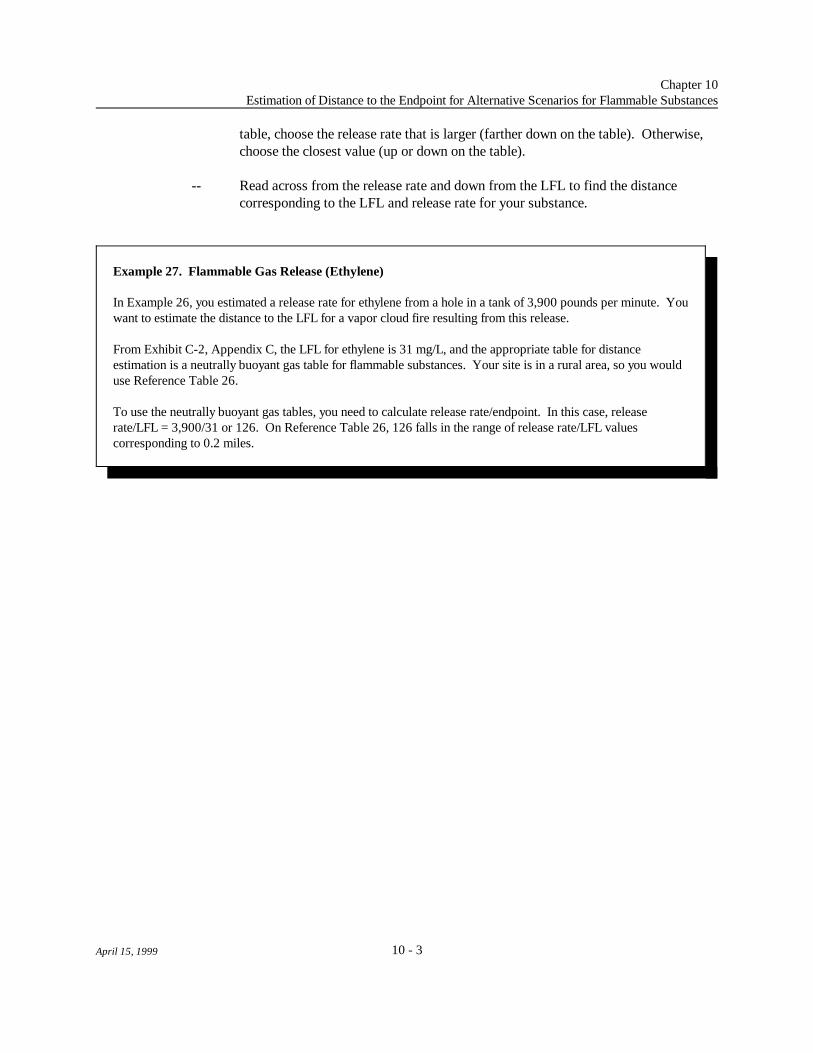
Chapter 10Estimation of Distance to the Endpoint for Alternative Scenarios for Flammable Substances
10 - 3April 15, 1999
Example 27. Flammable Gas Release (Ethylene)
In Example 26, you estimated a release rate for ethylene from a hole in a tank of 3,900 pounds per minute. Youwant to estimate the distance to the LFL for a vapor cloud fire resulting from this release.
From Exhibit C-2, Appendix C, the LFL for ethylene is 31 mg/L, and the appropriate table for distanceestimation is a neutrally buoyant gas table for flammable substances. Your site is in a rural area, so you woulduse Reference Table 26.
To use the neutrally buoyant gas tables, you need to calculate release rate/endpoint. In this case, releaserate/LFL = 3,900/31 or 126. On Reference Table 26, 126 falls in the range of release rate/LFL valuescorresponding to 0.2 miles.
table, choose the release rate that is larger (farther down on the table). Otherwise,choose the closest value (up or down on the table).
-- Read across from the release rate and down from the LFL to find the distancecorresponding to the LFL and release rate for your substance.

Chapter 10Estimation of Distance to the Endpoint for Alternative Scenarios for Flammable Substances
10 - 4April 15, 1999
Example 28. Vapor Cloud Fire from Evaporating Pool of Flammable Liquid
You have a tank containing 20,000 pounds of ethyl ether. A likely scenario for a release might be shearing of apipe from the tank, with the released liquid forming a pool. You want to estimate the consequences of a vaporcloud fire that might result from evaporation of the pool and ignition of the vapor.
You first need to estimate the rate of release of the liquid from the tank. You can do this using Equation 7-4,Section 7.2.1. For this calculation, you need the area of the hole that would result from shearing the pipe (HA),the height of the liquid in the tank above the hole (LH), and the liquid leak factor (LLF) for ethyl ether, fromExhibit C-3 in Appendix C. The pipe diameter is 2 inches, so the cross sectional area of the hole would be 3.1square inches. You estimate that the pipe is 2 feet, or 24 inches, below the level of the liquid when the tank isfull. The square root of LH (24 inches) is 4.9. LLF for ethyl ether is 34. From Equation 7-4, the rate of releaseof the liquid from the hole is calculated as:
QR = 3.1 × 4.9 × 34L
= 520 pounds per minute
You estimate that the release of the liquid could be stopped in about 10 minutes. In 10 minutes, 10 × 520, or5,200 pounds, would be released.
The liquid would be released into an area without dikes. To estimate the evaporation rate from the pool formedby the released liquid, you use Equation 7-8 from Section 7.2.3. To carry out the calculation, you need theLiquid Factor Ambient (LFA) and the Density Factor (DF) for ethyl ether. From Exhibit C-3, Appendix C,LFA for ethyl ether is 0.11 and DF is 0.69. The release rate to air is:
QR = 5,200 × 2.4 × 0.11 × 0.69= 950 pounds per minute
The evaporation rate from the pool is greater than the estimated liquid release rate; therefore, you use the liquidrelease rate of 520 pounds per minute as the release rate to air. To estimate the maximum distance at whichpeople in the area of the vapor cloud could suffer serious injury, estimate the distance to the lower flammabilitylimit (LFL) (in milligrams per liter) for ethyl ether, from the appropriate reference table. From Exhibit C-3,Appendix C, LFL for ethyl ether is 57 mg/L, and the appropriate reference table is a dense gas table. Your siteis in a rural area with few obstructions, so you use Reference Table 28.
From Reference Table 28, the closest LFL is 60 mg/L. The lowest release rate on the table is 1,500 pounds perminute, which is higher than the evaporation rate estimated for the pool of ethyl ether. For a release rate lessthan 1,500 pounds per minute, the distance to the LFL is less than 0.1 miles.
d PFF × A
Chapter 10Estimation of Distance to the Endpoint for Alternative Scenarios for Flammable Substances
10 - 5April 15, 1999
(10-1)
10.2 Pool Fires
Pool fires may be considered as potential alternative scenarios for flammable liquids, including gasesliquefied by refrigeration alone. You may find, however, that other scenarios will give a greater distance tothe endpoint and, therefore, may be more appropriate as alternative scenarios. A "Pool Fire Factor" (PFF)has been derived for each of the regulated flammable liquids and most of the flammable gases to aid in theconsequence analysis. The derivation of these factors is discussed in Appendix D, Section D.9. The PFF,listed in Appendix C, Exhibit C-2 for flammable gases and C-3 for flammable liquids, may be used toestimate a distance from the center of a pool fire where people could potentially receive second degree burnsfrom a 40-second exposure. The heat radiation endpoint for this analysis is 5 kilowatts per square meter(kW/m ). Ambient temperature is assumed to be 25 C (77 F) for calculation of the PFF for flammable2 o o
liquids.
To estimate a distance using the PFF, you first need to estimate the size of the pool, in square feet,that might be formed by the release of a flammable substance. You may use the methods described above fortoxic liquids to estimate pool size. Density factors (DF) for the estimation of pool size in undiked areas maybe found for flammable gases and flammable liquids in Exhibits C-2 and C-3 of Appendix C. For flammablegases, the DF is based on the density at the boiling point. You may want to consider whether the releasedsubstance may evaporate too quickly to form a pool of the maximum size, particularly for liquefied gases.
Distances may be estimated from the PFF and the pool area as follows:
where: d = Distance (feet)PFF = Pool Fire Factor (listed for each flammable substance in Appendix C,
Exhibits C-2 and C-3)A = Pool area (square feet)

Chapter 10Estimation of Distance to the Endpoint for Alternative Scenarios for Flammable Substances
10 - 6April 15, 1999
Example 29. Pool Fire of Flammable Liquid
For a tank containing 20,000 pounds of ethyl ether, you want to estimate the consequences of a pool fire. Youestimate that 15,000 pounds would be released into an area without dikes, forming a pool. Assuming the liquidspreads to a depth of 1 centimeter (0.39 inches), you estimate the area of the pool formed from Equation 3-6,Section 3.2.3. For this calculation, you need the density factor (DF) for ethyl ether; from Exhibit C-3,Appendix C, DF for ethyl ether is 0.69. From Equation 3-6, the area of the pool is:
A = 15,000 × 0.69 = 10,400 square feet
You can use Equation 10-1 to estimate the distance from the center of the burning pool where the heat radiationlevel would reach 5 kW/m . For the calculation, you need the square root of the pool area (A) and the pool fire2
factor (PFF) for ethyl ether. The square root of A, 10,400 square feet, is 102 feet. From Exhibit C-3,Appendix C, PFF for ethyl ether is 4.3. From Equation 10-1, the distance (d) to 5 kW/m is:2
d = 4.3 × 102 = 440 feet (about 0.08 miles)
If you have a gas that is liquefied under pressure or under a combination of pressure andrefrigeration, a pool fire is probably not an appropriate alternative scenario. A fire or explosion involving theflammable gas that is released to the air by a sudden release of pressure is likely to have the potential forserious effects at a greater distance than a pool fire (e.g., see the methods for analysis of BLEVEs and vaporcloud explosions in Sections 10.3 and 10.4 below, or see Appendix A for references that provide moreinformation on consequence analysis for fires and explosions).
10.3 BLEVEs
If a fireball from a BLEVE is a potential release scenario at your site, you may use Reference Table30 to estimate the distance to a potentially harmful radiant heat level. The table shows distances for a rangeof quantities to the radiant heat level that potentially could cause second degree burns to a person exposed forthe duration of the fire. The quantity you use should be the total quantity in a tank that might be involved in aBLEVE. The equations used to derive this table of distances are presented in Appendix D, Section D.10. Ifyou prefer, you may use the equations to estimate a distance for BLEVEs, or you may use a differentcalculation method or model.
10.4 Vapor Cloud Explosion
If you have the potential at your site for the rapid release of a large quantity of a flammable vapor,particularly into a congested area, a vapor cloud explosion may be an appropriate alternative release scenario. For the consequence analysis, you may use the same methods as for the worst case to estimate consequencedistances to an overpressure endpoint of 1 psi (see Section 5.1 and the equation in Appendix C). Instead ofassuming the total quantity of flammable substance released is in the vapor cloud, you may estimate a smaller

QF FFF × QS × 2
Chapter 10Estimation of Distance to the Endpoint for Alternative Scenarios for Flammable Substances
10 - 7April 15, 1999
(10-2)
quantity in the cloud. You could base your estimate of the quantity in the cloud on the release rate estimatedas described above for gases and liquids multiplied by the time required to stop the release.
To estimate the quantity in the cloud for a gas liquefied under pressure (not refrigerated), you mayuse the equation below. This equation incorporates a "flash fraction factor" (FFF), listed in Appendix C,Exhibit C-2 for regulated flammable gases, to estimate the quantity that could be immediately flashed intovapor upon release. A factor of two is included to estimate the quantity that might be carried along as sprayor aerosol. See Appendix D, Section D.11 for the derivation of this equation. The equation is:
where: QF = Quantity flashed into vapor plus aerosol (pounds) (cannot be larger thanQS)
FFF = Flash fraction factor (unitless) (listed in Appendix C, Exhibit C-2) (must beless than 1)
QS = Quantity spilled (pounds)2 = Factor to account for spray and aerosol
For derivation of the FFF, the temperature of the stored gas was assumed to be 25 C (77 F) (excepto o
as noted in Exhibit C-2). You may estimate the flash fraction under other conditions using the equationpresented in Appendix D, Section D.11.
You may estimate the distance to 1 psi for a vapor cloud explosion from the quantity in the cloudusing Reference Table 13 (at the end of the worst-case analysis discussion) or from Equation C-1 inAppendix C. For the alternative scenario analysis, you may use a yield factor of 3 percent, instead of theyield factor of 10 percent used in the worst-case analysis. As discussed in Appendix D, Section D.11, theyield factor of 3 percent is representative of more likely events, based on data from past vapor cloudexplosions. If you use the equation in Appendix C, use 0.03 instead of 0.1 in the calculation. If you useReference Table 13, you can incorporate the lower yield factor by multiplying the distance you read fromReference Table 13 by 0.67.

Chapter 10Estimation of Distance to the Endpoint for Alternative Scenarios for Flammable Substances
10 - 8April 15, 1999
Example 30. Vapor Cloud Explosion (Propane)
You have a tank containing 50,000 pounds of propane liquefied under pressure at ambient temperature. Youwant to estimate the consequence distance for a vapor cloud explosion resulting from rupture of the tank.
You use Equation 10-2 to estimate the quantity that might be released to form a cloud. You base thecalculation on the entire contents of the tank (QS = 50,000 pounds). From Exhibit C-2 of Appendix C, theFlash Fraction Factor (FFF) for propane is 0.38. From Equation 10-2, the quantity flashed into vapor, plus thequantity that might be carried along as aerosol, (QF) is:
QF = 0.38 × 50,000 × 2 = 38,000 pounds
You assume 38,000 pounds of propane is in the flammable part of the vapor cloud. This quantity falls between20,000 pounds and 50,000 pounds in Reference Table 13; 50,000 pounds is the quantity closest to yourquantity. From the table, the distance to 1 psi overpressure is 0.3 mile for 50,000 pounds of propane for a 10percent yield factor. To change the yield factor to 3 percent, you multiply this distance by 0.67; then thedistance becomes 0.2 mile.

10 - 9April 15, 1999
Reference Table 14Neutrally Buoyant Plume Distances to Toxic Endpoint for Release Rate Divided by Endpoint
10-Minute Release, Rural Conditions, D Stability, Wind Speed 3.0 Meters per Second
Release Rate/Endpoint Distance to Release Rate/Endpoint Distance to[(lbs/min)/(mg/L)] Endpoint [(lbs/min)/(mg/L)] Endpoint
(miles) (miles)
0 - 64 0.1 130,000 - 140,000 4.8
64 - 510 0.2 140,000 - 160,000 5.0
510 - 1,300 0.3 160,000 - 180,000 5.2
1,300 - 2,300 0.4 180,000 - 190,000 5.4
2,300 - 4,100 0.6 190,000 - 210,000 5.6
4,100 - 6,300 0.8 210,000 - 220,000 5.8
6,300 - 8,800 1.0 220,000 - 240,000 6.0
8,800 - 12,000 1.2 240,000 - 261,000 6.2
12,000 - 16,000 1.4 261,000 - 325,000 6.8
16,000 - 19,000 1.6 325,000 - 397,000 7.5
19,000 - 22,000 1.8 397,000 - 477,000 8.1
22,000 - 26,000 2.0 477,000 - 566,000 8.7
26,000 - 30,000 2.2 566,000 - 663,000 9.3
30,000 - 36,000 2.4 663,000 - 769,000 9.9
36,000 - 42,000 2.6 769,000 - 1,010,000 11
42,000 - 47,000 2.8 1,010,000 - 1,280,000 12
47,000 - 54,000 3.0 1,280,000 - 1,600,000 14
54,000 - 60,000 3.2 1,600,000 - 1,950,000 15
60,000 - 70,000 3.4 1,950,000 - 2,340,000 16
70,000 - 78,000 3.6 2,340,000 - 2,770,000 17
78,000 - 87,000 3.8 2,770,000 - 3,240,000 19
87,000 - 97,000 4.0 3,240,000 - 4,590,000 22
97,000 - 110,000 4.2 4,590,000 - 6,190,000 25
110,000 - 120,000 4.4 >6,190,000 >25*
120,000 - 130,000 4.6
*Report distance as 25 miles

10 - 10April 15, 1999
Reference Table 15Neutrally Buoyant Plume Distances to Toxic Endpoint for Release Rate Divided by Endpoint
60-Minute Release, Rural Conditions, D Stability, Wind Speed 3.0 Meters per Second
Release Rate/Endpoint Distance to Release Rate/Endpoint Distance to[(lbs/min)/(mg/L)] Endpoint [(lbs/min)/(mg/L)] Endpoint
(miles) (miles)
0 - 79 0.1 100,000 - 108,000 4.8
79 - 630 0.2 108,000 - 113,000 5.0
630 - 1,600 0.3 113,000 - 120,000 5.2
1,600 - 2,800 0.4 120,000 - 126,000 5.4
2,800 - 5,200 0.6 126,000 - 132,000 5.6
5,200 - 7,900 0.8 132,000 - 140,000 5.8
7,900 - 11,000 1.0 140,000 - 150,000 6.0
11,000 - 14,000 1.2 150,000 - 151,000 6.2
14,000 - 19,000 1.4 151,000 - 171,000 6.8
19,000 - 23,000 1.6 171,000 - 191,000 7.5
23,000 - 27,000 1.8 191,000 - 212,000 8.1
27,000 - 32,000 2.0 212,000 - 233,000 8.7
32,000 - 36,000 2.2 233,000 - 256,000 9.3
36,000 - 42,000 2.4 256,000 - 280,000 9.9
42,000 - 47,000 2.6 280,000 - 332,000 11
47,000 - 52,000 2.8 332,000 - 390,000 12
52,000 - 57,000 3.0 390,000 - 456,000 14
57,000 - 61,000 3.2 456,000 - 529,000 15
61,000 - 68,000 3.4 529,000 - 610,000 16
68,000 - 73,000 3.6 610,000 - 699,000 17
73,000 - 79,000 3.8 699,000 - 796,000 19
79,000 - 84,000 4.0 796,000 - 1,080,000 22
84,000 - 91,000 4.2 1,080,000 - 1,410,000 25
91,000 - 97,000 4.4 >1,410,000 >25*
97,000 - 100,000 4.6
*Report distance as 25 miles

10 - 11April 15, 1999
Reference Table 16Neutrally Buoyant Plume Distances to Toxic Endpoint for Release Rate Divided by Endpoint
10-Minute Release, Urban Conditions, D Stability, Wind Speed 3.0 Meters per Second
Release Rate/Endpoint Distance to Endpoint Release Rate/Endpoint Distance to[(lbs/min)/(mg/L)] (miles) [(lbs/min)/(mg/L)] Endpoint
(miles)
0 - 160 0.1 600,000 - 660,000 4.8
160 - 1,400 0.2 660,000 - 720,000 5.0
1,400 - 3,600 0.3 720,000 - 810,000 5.2
3,600 - 6,900 0.4 810,000 - 880,000 5.4
6,900 - 13,000 0.6 880,000 - 950,000 5.6
13,000 - 22,000 0.8 950,000 - 1,000,000 5.8
22,000 - 31,000 1.0 1,000,000 - 1,100,000 6.0
31,000 - 42,000 1.2 1,100,000 - 1,220,000 6.2
42,000 - 59,000 1.4 1,220,000 - 1,530,000 6.8
59,000 - 73,000 1.6 1,530,000 - 1,880,000 7.5
73,000 - 88,000 1.8 1,880,000 - 2,280,000 8.1
88,000 - 100,000 2.0 2,280,000 - 2,710,000 8.7
100,000 - 120,000 2.2 2,710,000 - 3,200,000 9.3
120,000 - 150,000 2.4 3,200,000 - 3,730,000 9.9
150,000 - 170,000 2.6 3,730,000 - 4,920,000 11
170,000 - 200,000 2.8 4,920,000 - 6,310,000 12
200,000 - 230,000 3.0 6,310,000 - 7,890,000 14
230,000 - 260,000 3.2 7,890,000 - 9,660,000 15
260,000 - 310,000 3.4 9,660,000 - 11,600,000 16
310,000 - 340,000 3.6 11,600,000 - 13,800,000 17
340,000 - 390,000 3.8 13,800,000 - 16,200,000 19
390,000 - 430,000 4.0 16,200,000 - 23,100,000 22
430,000 - 490,000 4.2 23,100,000 - 31,300,000 25
490,000 - 540,000 4.4 >31,300,000 >25*
540,000 - 600,000 4.6
*Report distance as 25 miles

10 - 12April 15, 1999
Reference Table 17Neutrally Buoyant Plume Distances to Toxic Endpoint for Release Rate Divided by Endpoint
60-Minute Release, Urban Conditions, D Stability, Wind Speed 3.0 Meters per Second
Release Rate/Endpoint Distance to Release Rate/Endpoint Distance to[(lbs/min)/(mg/L)] Endpoint [(lbs/min)/(mg/L)] Endpoint
(miles) (miles)
0 - 200 0.1 460,000 - 490,000 4.8
200 - 1,700 0.2 490,000 - 520,000 5.0
1,700 - 4,500 0.3 520,000 - 550,000 5.2
4,500 - 8,600 0.4 550,000 - 580,000 5.4
8,600 - 17,000 0.6 580,000 - 610,000 5.6
17,000 - 27,000 0.8 610,000 - 640,000 5.8
27,000 - 39,000 1.0 640,000 - 680,000 6.0
39,000 - 53,000 1.2 680,000 - 705,000 6.2
53,000 - 73,000 1.4 705,000 - 804,000 6.8
73,000 - 90,000 1.6 804,000 - 905,000 7.5
90,000 - 110,000 1.8 905,000 - 1,010,000 8.1
110,000 - 130,000 2.0 1,010,000 - 1,120,000 8.7
130,000 - 150,000 2.2 1,120,000 - 1,230,000 9.3
150,000 - 170,000 2.4 1,230,000 - 1,350,000 9.9
170,000 - 200,000 2.6 1,350,000 - 1,620,000 11
200,000 - 220,000 2.8 1,620,000 - 1,920,000 12
220,000 - 240,000 3.0 1,920,000 - 2,250,000 14
240,000 - 270,000 3.2 2,250,000 - 2,620,000 15
270,000 - 300,000 3.4 2,620,000 - 3,030,000 16
300,000 - 320,000 3.6 3,030,000 - 3,490,000 17
320,000 - 350,000 3.8 3,490,000 - 3,980,000 19
350,000 - 370,000 4.0 3,980,000 - 5,410,000 22
370,000 - 410,000 4.2 5,410,000 - 7,120,000 25
410,000 - 430,000 4.4 >7,120,000 >25*
430,000 - 460,000 4.6
*Report distance as 25 miles

10 - 13
Reference Table 18Dense Gas Distances to Toxic Endpoint
10-minute Release, Rural Conditions, D Stability, Wind Speed 3.0 Meters per Second
ReleaseRate
(lbs/min)
Toxic Endpoint (mg/L)
0.0004 0.0007 0.001 0.002 0.0035 0.005 0.0075 0.01 0.02 0.035 0.05 0.075 0.1 0.25 0.5 0.75
Distance (Miles)
1 0.6 0.4 0.4 0.2 0.2 0.1 0.1 0.1 <0.1 <0.1 # # # # # #
2 0.9 0.6 0.5 0.4 0.3 0.2 0.2 0.1 0.1 0.1 <0.1 <0.1 # # # #
5 1.4 1.1 0.9 0.6 0.4 0.4 0.3 0.2 0.2 0.1 0.1 0.1 <0.1 # # #
10 2.0 1.5 1.2 0.9 0.6 0.5 0.4 0.4 0.2 0.2 0.1 0.1 0.1 <0.1 <0.1 #
30 3.7 2.7 2.2 1.5 1.1 0.9 0.7 0.7 0.5 0.3 0.3 0.2 0.2 0.1 0.1 <0.1
50 5.0 3.7 3.0 2.1 1.9 1.2 1.0 0.9 0.6 0.4 0.4 0.3 0.2 0.2 0.1 0.1
100 7.4 5.3 4.3 3.0 2.3 1.7 1.4 1.2 0.9 0.6 0.6 0.4 0.4 0.2 0.2 0.1
150 8.7 6.8 5.5 3.8 2.8 2.3 1.9 1.6 1.1 0.8 0.7 0.6 0.5 0.3 0.2 0.2
250 12 8.7 7.4 5.0 3.7 3.0 2.4 2.1 1.4 1.1 0.9 0.7 0.5 0.4 0.3 0.2
500 17 13 11 7.4 5.3 4.5 3.6 3.0 2.1 1.6 1.3 1.1 0.9 0.6 0.4 0.3
750 22 16 13 9.3 6.8 5.6 4.5 3.8 2.7 1.9 1.6 1.3 1.1 0.7 0.5 0.4
1,000 >25 19 16 11 8.1 6.8 5.2 4.5 3.1 2.3 2.2 1.5 1.3 0.8 0.6 0.4
1,500 * 23 19 13 9.9 8.1 6.8 5.6 3.9 2.9 2.4 1.9 1.6 1.0 0.7 0.6
2,000 * >25 22 15 12 9.3 7.4 6.8 4.5 3.4 2.7 2.2 1.9 1.2 0.8 0.6
2,500 * * 25 17 13 11 8.7 7.4 5.2 3.8 3.2 2.5 2.1 1.3 0.9 0.7
3,000 * * >25 19 14 12 9.3 8.1 5.7 4.2 3.5 2.8 2.4 1.4 1.0 0.8
4,000 * * * 22 17 14 11 9.3 6.8 4.9 4.1 3.3 2.8 1.7 1.1 0.9
5,000 * * * >25 19 16 12 11 7.4 5.6 4.7 3.7 3.1 2.1 1.3 1.1
7,500 * * * * 24 19 16 13 9.3 6.8 5.8 4.7 4.0 2.4 1.6 1.3
10,000 * * * * >25 22 18 16 11 8.1 6.8 5.3 4.6 2.8 1.9 1.5
15,000 * * * * * >25 22 19 13 9.9 8.1 6.8 5.7 3.5 2.4 1.9
20,000 * * * * * * >25 22 16 11 9.3 7.4 6.8 4.0 2.8 2.2
50,000 * * * * * * * >25 24 18 15 12 10 6.5 4.5 3.6
75,000 * * * * * * * * >25 22 18 15 13 7.8 5.4 4.4
100,000 * * * * * * * * * >25 21 17 14 8.9 6.3 5.0
150,000 * * * * * * * * * * >25 20 17 11 7.4 6.0
200,000 * * * * * * * * * * * 23 19 12 8.5 6.8
* > 25 miles (report distance as 25 miles) # <0.1 mile (report distance as 0.1 mile)

10 - 14
Reference Table 19Dense Gas Distances to Toxic Endpoint
60-minute Release, Rural Conditions, D Stability, Wind Speed 3.0 Meters per Second
ReleaseRate
(lbs/min)
Toxic Endpoint (mg/L)
0.0004 0.0007 0.001 0.002 0.0035 0.005 0.0075 0.01 0.02 0.035 0.05 0.075 0.1 0.25 0.5 0.75
Distance (Miles)
1 0.5 0.4 0.3 0.2 0.2 0.1 0.1 0.1 <0.1 # # # # # # #
2 0.8 0.6 0.5 0.3 0.2 0.2 0.2 0.1 0.1 <0.1 <0.1 <0.1 # # # #
5 1.6 1.0 0.8 0.5 0.4 0.3 0.2 0.2 0.2 0.1 0.1 0.1 <0.1 # # #
10 2.0 1.4 1.2 0.8 0.6 0.5 0.4 0.3 0.2 0.2 0.1 0.1 0.1 <0.1 <0.1 #
30 4.0 2.8 2.2 1.5 1.1 0.9 0.7 0.6 0.4 0.3 0.2 0.2 0.2 0.1 0.1 <0.1
50 5.5 3.9 3.1 2.1 1.5 1.2 1.0 0.8 0.6 0.4 0.3 0.3 0.2 0.1 0.1 0.1
100 8.7 6.1 4.8 3.2 2.2 1.8 1.4 1.2 0.8 0.6 0.5 0.4 0.3 0.2 0.1 0.1
150 12 8.1 6.2 4.1 2.9 2.3 1.8 1.6 1.1 0.7 0.6 0.5 0.4 0.3 0.2 0.1
250 17 11 8.7 5.6 4.0 3.2 2.5 2.1 1.4 1.1 0.9 0.7 0.6 0.4 0.2 0.2
500 >25 19 14 9.3 6.2 5.0 3.9 3.3 2.2 1.6 1.3 1.0 0.9 0.5 0.4 0.3
750 * 25 19 12 8.7 6.8 5.1 4.2 2.8 2.0 1.6 1.3 1.1 0.6 0.4 0.4
1,000 * >25 24 15 11 8.1 6.1 5.2 3.4 2.4 1.9 1.5 1.3 0.7 0.5 0.4
1,500 * * >25 20 14 11 8.1 6.8 4.3 3.0 2.5 1.9 1.7 1.0 0.7 0.5
2,000 * * * 24 17 13 9.9 8.1 5.2 3.7 2.9 2.3 1.9 1.2 0.7 0.6
2,500 * * * >25 19 15 12 9.3 6.0 4.3 3.4 2.7 2.2 1.3 0.9 0.7
3,000 * * * * 22 17 13 11 6.8 4.8 3.8 3.0 2.5 1.5 1.0 0.8
4,000 * * * * >25 21 16 14 8.7 5.8 4.7 3.6 3.0 1.7 1.2 0.9
5,000 * * * * * 25 19 16 9.9 6.8 5.3 4.1 3.5 2.0 1.4 1.1
7,500 * * * * * >25 25 20 13 9.3 6.8 5.4 4.5 2.6 1.7 1.4
10,000 * * * * * * >25 25 16 11 8.7 6.8 5.4 3.1 2.1 1.6
15,000 * * * * * * * >25 21 14 11 8.7 7.4 4.0 2.6 2.1
20,000 * * * * * * * * 25 17 14 11 8.7 4.8 3.1 2.5
50,000 * * * * * * * * >25 >25 25 19 16 8.8 5.6 4.3
75,000 * * * * * * * * * * >25 25 20 11 7.3 5.6
100,000 * * * * * * * * * * * >25 24 14 9.4 6.8
150,000 * * * * * * * * * * * * >25 17 11 8.7
200,000 * * * * * * * * * * * * * 20 13 10
* > 25 miles (report distance as 25 miles) # <0.1 mile (report distance as 0.1 mile)

10 - 15
Reference Table 20Dense Gas Distances to Toxic Endpoint
10-minute Release, Urban Conditions, D Stability, Wind Speed 3.0 Meters per Second
ReleaseRate
(lbs/min)
Toxic Endpoint (mg/L)
0.0004 0.0007 0.001 0.002 0.0035 0.005 0.0075 0.01 0.02 0.035 0.05 0.075 0.1 0.25 0.5 0.75
Distance (Miles)
1 0.5 0.3 0.2 0.2 0.1 0.1 0.1 0.1 <0.1 # # # # # # #
2 0.7 0.5 0.4 0.3 0.2 0.2 0.1 0.1 0.1 <0.1 <0.1 # # # # #
5 1.1 0.8 0.6 0.5 0.3 0.3 0.2 0.2 0.1 0.1 0.1 <0.1 <0.1 # # #
10 2.1 1.2 1.0 0.7 0.5 0.4 0.3 0.3 0.2 0.1 0.1 0.1 0.1 <0.1 # #
30 3.0 2.2 1.9 1.2 0.9 0.8 0.6 0.6 0.4 0.3 0.2 0.2 0.1 0.1 <0.1 #
50 4.1 3.0 2.5 1.6 1.2 1.0 0.8 0.7 0.5 0.3 0.3 0.2 0.2 0.1 0.1 <0.1
100 5.8 4.3 3.5 2.7 1.8 1.4 1.2 1.0 0.7 0.6 0.4 0.4 0.3 0.2 0.1 0.1
150 7.4 5.5 4.5 3.1 2.2 1.9 1.4 1.2 0.9 0.7 0.6 0.4 0.4 0.2 0.2 0.1
250 9.9 7.4 5.8 4.1 3.0 2.5 2.0 1.7 1.1 0.9 0.7 0.6 0.5 0.3 0.2 0.1
500 14 11 8.7 5.9 4.3 3.6 2.9 2.5 1.7 1.2 1.0 0.8 0.7 0.4 0.3 0.2
750 17 13 11 7.4 5.5 4.5 3.6 3.1 2.1 1.6 1.2 1.0 0.9 0.5 0.4 0.3
1,000 20 15 12 8.7 6.2 5.3 4.3 3.5 2.5 1.8 1.5 1.2 1.0 0.6 0.4 0.3
1,500 >25 19 16 11 8.1 6.2 5.2 4.5 3.0 2.2 1.8 1.5 1.2 0.7 0.5 0.4
2,000 * 22 18 12 9.3 7.4 6.2 5.2 3.7 2.7 2.2 1.7 1.4 0.9 0.6 0.5
2,500 * 24 20 14 11 8.7 6.8 6.0 3.8 3.0 2.2 1.9 1.7 1.0 0.7 0.6
3,000 * >25 22 16 11 9.3 7.4 6.8 4.5 3.3 2.7 2.1 1.9 1.1 0.7 0.6
4,000 * * >25 18 14 11 8.7 7.4 5.3 4.0 3.2 2.6 2.1 1.2 0.9 0.7
5,000 * * * 20 15 12 9.9 8.7 5.8 4.4 3.6 2.9 2.4 1.4 0.9 0.7
7,500 * * * >25 19 16 12 11 7.4 5.5 4.5 3.6 3.0 1.8 1.2 0.9
10,000 * * * * 22 18 14 12 8.7 6.2 5.2 4.2 3.6 2.1 1.4 1.1
15,000 * * * * >25 22 18 16 11 8.1 6.8 5.2 4.4 2.6 1.7 1.3
20,000 * * * * * >25 20 18 12 9.3 7.4 6.0 5.2 3.0 2.0 1.6
50,000 * * * * * * >25 >25 20 15 12 9.7 8.3 5.0 3.3 2.6
75,000 * * * * * * * * 25 18 15 12 10 6.1 4.1 3.1
100,000 * * * * * * * * >25 21 17 14 12 7.0 4.7 3.7
150,000 * * * * * * * * * >25 21 17 14 8.5 5.7 4.5
200,000 * * * * * * * * * * 24 19 16 9.7 6.5 5.1
* > 25 miles (report distance as 25 miles) # <0.1 mile (report distance as 0.1 mile)

10 - 16
Reference Table 21Dense Gas Distances to Toxic Endpoint
60-minute Release, Urban Conditions, D Stability, Wind Speed 3.0 Meters per Second
ReleaseRate
(lbs/min)
Toxic Endpoint (mg/L)
0.0004 0.0007 0.001 0.002 0.0035 0.005 0.0075 0.01 0.02 0.035 0.05 0.075 0.1 0.25 0.5 0.75
Distance (Miles)
1 0.4 0.3 0.2 0.2 0.1 0.1 0.1 <0.1 # # # # # # # #
2 0.7 0.5 0.4 0.2 0.2 0.2 0.1 0.1 <0.1 <0.1 # # # # # #
5 1.1 0.8 0.7 0.4 0.3 0.2 0.2 0.2 0.1 0.1 <0.1 <0.1 <0.1 # # #
10 1.7 1.2 1.0 0.7 0.5 0.4 0.3 0.3 0.2 0.1 0.1 0.1 0.1 <0.1 # #
30 3.3 2.4 1.9 1.3 0.9 0.7 0.6 0.5 0.3 0.2 0.2 0.2 0.1 0.1 <0.1 #
50 4.7 3.3 2.6 1.7 1.2 1.0 0.8 0.7 0.4 0.3 0.3 0.2 0.2 0.1 0.1 <0.1
100 7.4 5.2 4.1 2.7 1.9 1.5 1.2 1.0 0.7 0.5 0.4 0.3 0.3 0.2 0.1 0.1
150 9.9 6.8 5.3 3.4 2.4 1.9 1.5 1.3 0.9 0.6 0.5 0.4 0.3 0.2 0.1 0.1
250 14 9.3 7.4 4.7 3.4 2.7 2.1 1.7 1.1 0.8 0.7 0.5 0.4 0.3 0.2 0.1
500 22 16 12 7.4 5.2 4.2 3.2 2.7 1.7 1.2 1.0 0.8 0.7 0.4 0.2 0.2
750 >25 20 16 9.9 6.8 5.4 4.2 3.5 2.2 1.6 1.3 1.0 0.9 0.5 0.3 0.3
1,000 * 24 19 12 8.1 6.8 5.0 4.2 2.7 1.8 1.6 1.2 1.0 0.6 0.4 0.3
1,500 * >25 >25 16 11 8.7 6.8 5.5 3.5 1.9 2.0 1.6 1.3 0.7 0.5 0.4
2,000 * * * 19 14 11 8.1 6.8 4.2 3.0 2.2 1.9 1.6 0.9 0.6 0.4
2,500 * * * 23 16 12 9.3 7.4 4.9 3.4 2.7 2.1 1.7 1.0 0.6 0.5
3,000 * * * >25 18 14 11 8.7 5.5 3.8 3.0 2.4 2.0 1.1 0.7 0.6
4,000 * * * * 22 17 13 11 6.8 4.7 3.1 2.8 2.4 1.3 0.9 0.7
5,000 * * * * >25 20 16 12 8.1 5.3 4.3 3.3 2.7 1.5 1.0 0.7
7,500 * * * * * 25 20 17 11 6.8 5.6 4.3 3.5 2.0 1.2 0.9
10,000 * * * * * >25 24 20 13 8.7 6.8 5.2 4.3 2.4 1.5 1.1
15,000 * * * * * * >25 >25 17 11 8.7 6.8 5.6 3.0 1.9 1.5
20,000 * * * * * * * * 20 14 11 8.1 6.8 3.6 2.3 1.7
50,000 * * * * * * * * >25 >25 20 15 13 6.6 4.0 3.1
75,000 * * * * * * * * * * >25 20 16 8.7 5.3 3.9
100,000 * * * * * * * * * * * 24 20 10 6.3 4.7
150,000 * * * * * * * * * * * >25 >25 14 8.2 6.1
200,000 * * * * * * * * * * * * * 16 9.9 7.3
* > 25 miles (report distance as 25 miles) # <0.1 mile (report distance as 0.1 mile)

10 - 17April 15, 1999
Reference Table 22Distances to Toxic Endpoint for Anhydrous Ammonia Liquefied Under Pressure
D Stability, Wind Speed 3.0 Meters per Second
Release Rate Distance to Endpoint (miles) Release Rate Distance to Endpoint (miles)(lbs/min) (lbs/min)
Rural Urban Rural Urban
<10 <0.1* 900 0.6 0.2
<0.1*
10 0.1 1,000 0.6 0.2
15 0.1 1,500 0.7 0.3
20 0.1 2,000 0.8 0.3
30 0.1 2,500 0.9 0.3
40 0.1 3,000 1.0 0.4
50 0.1 4,000 1.2 0.4
60 0.2 0.1 5,000 1.3 0.5
70 0.2 0.1 7,500 1.6 0.5
80 0.2 0.1 10,000 1.8 0.6
90 0.2 0.1 15,000 2.2 0.7
100 0.2 0.1 20,000 2.5 0.8
150 0.2 0.1 25,000 2.8 0.9
200 0.3 0.1 30,000 3.1 1.0
250 0.3 0.1 40,000 3.5 1.1
300 0.3 0.1 50,000 3.9 1.2
400 0.4 0.2 75,000 4.8 1.4
500 0.4 0.2 100,000 5.4 1.6
600 0.5 0.2 150,000 6.6 1.9
700 0.5 0.2 200,000 7.6 2.1
750 0.5 0.2 250,000 8.4 2.3
800 0.5 0.2
* Report distance as 0.1 mile

10 - 18April 15, 1999
Reference Table 23Distances to Toxic Endpoint for Non-liquefied Ammonia, Ammonia Liquefied by Refrigeration, or
Aqueous AmmoniaD Stability, Wind Speed 3.0 Meters per Second
Release Rate Distance to Endpoint (miles) Release Rate Distance to Endpoint (miles)(lbs/min) (lbs/min)
Rural Urban Rural Urban
<8 <0.1* 800 0.7 0.2
<0.1*
8 0.1 900 0.7 0.3
10 0.1 1,000 0.8 0.3
15 0.1 1,500 1.0 0.4
20 0.1 2,000 1.2 0.4
30 0.1 2,500 1.2 0.4
40 0.1 3,000 1.5 0.5
50 0.2 0.1 4,000 1.8 0.6
60 0.2 0.1 5,000 2.0 0.7
70 0.2 0.1 7,500 2.2 0.7
80 0.2 0.1 10,000 2.5 0.8
90 0.2 0.1 15,000 3.1 1.0
100 0.2 0.1 20,000 3.6 1.2
150 0.3 0.1 25,000 4.1 1.3
200 0.3 0.1 30,000 4.4 1.4
250 0.4 0.2 40,000 5.1 1.6
300 0.4 0.2 50,000 5.8 1.8
400 0.4 0.2 75,000 7.1 2.2
500 0.5 0.2 100,000 8.2 2.5
600 0.6 0.2 150,000 10 3.1
700 0.6 0.2 200,000 12 3.5
750 0.6 0.2
* Report distance as 0.1 mile

10 - 19April 15, 1999
Reference Table 24Distances to Toxic Endpoint for Chlorine
D Stability, Wind Speed 3.0 Meters per Second
Release Rate Distance to Endpoint (miles) Release Rate Distance to Endpoint (miles)(lbs/min) (lbs/min)
Rural Urban Rural Urban
1 <0.1* 750 1.2 0.4<0.1*
2 0.1 800 1.2 0.5
5 0.1 900 1.2 0.5
10 0.2 0.1 1,000 1.3 0.5
15 0.2 0.1 1,500 1.6 0.6
20 0.2 0.1 2,000 1.8 0.6
30 0.3 0.1 2,500 2.0 0.7
40 0.3 0.1 3,000 2.2 0.8
50 0.3 0.1 4,000 2.5 0.8
60 0.4 0.2 5,000 2.8 0.9
70 0.4 0.2 7,500 3.4 1.2
80 0.4 0.2 10,000 3.9 1.3
90 0.4 0.2 15,000 4.6 1.6
100 0.5 0.2 20,000 5.3 1.8
150 0.6 0.2 25,000 5.9 2.0
200 0.6 0.3 30,000 6.4 2.1
250 0.7 0.3 40,000 7.3 2.4
300 0.8 0.3 50,000 8.1 2.7
400 0.8 0.4 75,000 9.8 3.2
500 1.0 0.4 100,000 11 3.6
600 1.0 0.4 150,000 13 4.2
700 1.1 0.4 200,000 15 4.8
* Report distance as 0.1 mile

10 - 20April 15, 1999
Reference Table 25Distances to Toxic Endpoint for Sulfur DioxideD Stability, Wind Speed 3.0 Meters per Second
Release Rate Distance to Endpoint (miles) Release Rate Distance to Endpoint (miles)(lbs/min) (lbs/min)
Rural Urban Rural Urban
1 <0.1* 750 1.3 0.5<0.1*
2 0.1 800 1.3 0.5
5 0.1 900 1.4 0.5
10 0.2 0.1 1,000 1.5 0.5
15 0.2 0.1 1,500 1.9 0.6
20 0.2 0.1 2,000 2.2 0.7
30 0.2 0.1 2,500 2.3 0.8
40 0.3 0.1 3,000 2.7 0.8
50 0.3 0.1 4,000 3.1 1.0
60 0.4 0.2 5,000 3.3 1.1
70 0.4 0.2 7,500 4.0 1.3
80 0.4 0.2 10,000 4.6 1.4
90 0.4 0.2 15,000 5.6 1.7
100 0.5 0.2 20,000 6.5 1.9
150 0.6 0.2 25,000 7.3 2.1
200 0.6 0.2 30,000 8.0 2.3
250 0.7 0.3 40,000 9.2 2.6
300 0.8 0.3 50,000 10 2.9
400 0.9 0.4 75,000 13 3.5
500 1.0 0.4 100,000 14 4.0
600 1.1 0.4 150,000 18 4.7
700 1.2 0.4 200,000 20 5.4
* Report distance as 0.1 mile

10 - 21April 15, 1999
Reference Table 26Neutrally Buoyant Plume Distances to Lower Flammability Limit (LFL)
For Release Rate Divided by LFLRural Conditions, D Stability, Wind Speed 3.0 Meters per Second
Release Rate/Endpoint Distance to Release Rate/Endpoint Distance to[(lbs/min)/(mg/L)] Endpoint [(lbs/min)/(mg/L)] Endpoint
(miles) (miles)
0 - 28 0.1 2,700 - 3,300 0.9
28 - 40 0.1 3,300 - 3,900 1.0
40 - 60 0.1 3,900 - 4,500 1.1
60 - 220 0.2 4,500 - 5,200 1.2
220 - 530 0.3 5,200 - 5,800 1.3
530 - 860 0.4 5,800 - 6,800 1.4
860 - 1,300 0.5 6,800 - 8,200 1.6
1,300 - 1,700 0.6 8,200 - 9,700 1.8
1,700 - 2,200 0.7 9,700 - 11,000 2.0
2,200 - 2,700 0.8 11,000 - 13,000 2.2
Reference Table 27Neutrally Buoyant Plume Distances to Lower Flammability Limit (LFL)
For Release Rate Divided by LFLUrban Conditions, D Stability, Wind Speed 3.0 Meters per Second
Release Rate/Endpoint Distance to Release Rate/Endpoint Distance to[(lbs/min)/(mg/L)] Endpoint [(lbs/min)/(mg/L)] Endpoint
(miles) (miles)
0 - 68 0.1 5,500 - 7,300 0.7
68 - 100 0.1 7,300 - 9,200 0.8
100 - 150 0.1 9,200 - 11,000 0.9
150 - 710 0.2 11,000 - 14,000 1.0
710 - 1,500 0.3 14,000 - 18,000 1.2
1,500 - 2,600 0.4 18,000 - 26,000 1.4
2,600 - 4,000 0.5 26,000 - 31,000 1.6
4,000 - 5,500 0.6 31,000 - 38,000 1.8

10 - 22April 15, 1999
Reference Table 28Dense Gas Distances to Lower Flammability Limit
Rural Conditions, D Stability, Wind Speed 3.0 Meters per Second
ReleaseRate
(lbs/min)
Lower Flammability Limit (mg/L)
27 30 35 40 45 50 60 70 100 >100
Distance (Miles)
<1,500 # # # # # # # # # #
1,500 <0.1 <0.1 # # # # # # # #
2,000 0.1 0.1 <0.1 # # # # # # #
2,500 0.1 0.1 0.1 <0.1 # # # # # #
3,000 0.1 0.1 0.1 0.1 <0.1 <0.1 # # # #
4,000 0.1 0.1 0.1 0.1 0.1 0.1 <0.1 # # #
5,000 0.1 0.1 0.1 0.1 0.1 0.1 0.1 <0.1 # #
7,500 0.2 0.1 0.1 0.1 0.1 0.1 0.1 0.1 <0.1 #
10,000 0.2 0.2 0.1 0.1 0.1 0.1 0.1 0.1 0.1 <0.1
# < 0.1 mile (report distance as 0.1 mile)

10 - 23April 15, 1999
Reference Table 29Dense Gas Distances to Lower Flammability Limit
Urban Conditions, D Stability, Wind Speed 3.0 Meters per Second
ReleaseRate
(lbs/min)
Lower Flammability Limit (mg/L)
27 30 35 40 >40
Distance (Miles)
<5,000 # # # # #
5,000 <0.1 <0.1 # # #
7,500 0.1 0.1 <0.1 # #
10,000 0.1 0.1 0.1 <0.1 #
# < 0.1 mile (report distance as 0.1 mile)

10 - 24April 15, 1999
Reference Table 30Distance to Radiant Heat Dose at Potential Second Degree Burn Threshold Assuming Exposure for Duration of Fireball from BLEVE
(Dose = [5 kW/m ] x Exposure Time)2 4/3
Quantity in Fireball (pounds) 1,000 5,000 10,000 20,000 30,000 50,000 75,000 100,000 200,000 300,000 500,000
Duration of Fireball (seconds) 3.5 5.9 7.5 9.4 10.8 12.7 14.8 15.5 17.4 18.7 20.3
CAS No. Chemical Name Distance (miles) at which Exposure for Duration of Fireball May Cause Second Degree Burns
75-07-0 Acetaldehyde 0.04 0.08 0.1 0.1 0.2 0.2 0.3 0.3 0.4 0.5 0.6
74-86-2 Acetylene 0.05 0.1 0.1 0.2 0.2 0.3 0.4 0.4 0.5 0.6 0.8
598-73-2 Bromotrifluoroethylene 0.01 0.02 0.03 0.04 0.05 0.06 0.07 0.08 0.1 0.1 0.2
106-99-0 1,3-Butadiene 0.05 0.1 0.1 0.2 0.2 0.3 0.4 0.4 0.5 0.6 0.8
106-97-8 Butane 0.05 0.1 0.1 0.2 0.2 0.3 0.4 0.4 0.5 0.6 0.8
106-98-9 1-Butene 0.05 0.1 0.1 0.2 0.2 0.3 0.4 0.4 0.5 0.6 0.8
107-01-7 2-Butene 0.05 0.1 0.1 0.2 0.2 0.3 0.4 0.4 0.5 0.6 0.8
25167-67-3 Butene 0.05 0.1 0.1 0.2 0.2 0.3 0.4 0.4 0.5 0.6 0.8
590-18-1 2-Butene-cis 0.05 0.1 0.1 0.2 0.2 0.3 0.4 0.4 0.5 0.6 0.8
624-64-6 2-Butene-trans 0.05 0.1 0.1 0.2 0.2 0.3 0.4 0.4 0.5 0.6 0.8
463-58-1 Carbon oxysulfide 0.02 0.05 0.06 0.09 0.1 0.1 0.2 0.2 0.2 0.3 0.3
7791-21-1 Chlorine monoxide 0.01 0.02 0.02 0.03 0.03 0.04 0.05 0.06 0.08 0.09 0.1
557-98-2 2-Chloropropylene 0.03 0.07 0.1 0.1 0.2 0.2 0.2 0.3 0.4 0.4 0.5
590-21-6 1-Chloropropylene 0.03 0.07 0.1 0.1 0.2 0.2 0.2 0.3 0.4 0.4 0.5
460-19-5 Cyanogen 0.03 0.07 0.1 0.1 0.2 0.2 0.2 0.3 0.4 0.4 0.5
75-19-4 Cyclopropane 0.05 0.1 0.1 0.2 0.2 0.3 0.4 0.4 0.5 0.6 0.8
4109-96-0 Dichlorosilane 0.02 0.04 0.06 0.08 0.1 0.1 0.2 0.2 0.2 0.3 0.3
75-37-6 Difluoroethane 0.02 0.05 0.07 0.1 0.1 0.1 0.2 0.2 0.3 0.3 0.4
124-40-3 Dimethylamine 0.04 0.09 0.1 0.2 0.2 0.3 0.3 0.4 0.5 0.5 0.7
463-82-1 2,2-Dimethylpropane 0.05 0.1 0.1 0.2 0.2 0.3 0.4 0.4 0.5 0.6 0.8
74-84-0 Ethane 0.05 0.1 0.1 0.2 0.2 0.3 0.4 0.4 0.5 0.6 0.8
107-00-6 Ethyl acetylene 0.05 0.1 0.1 0.2 0.2 0.3 0.4 0.4 0.5 0.6 0.8

Reference Table 30 (continued)
Quantity in Fireball (pounds) 1,000 5,000 10,000 20,000 30,000 50,000 75,000 100,000 200,000 300,000 500,000
Duration of Fireball (seconds) 3.5 5.9 7.5 9.4 10.8 12.7 14.8 15.5 17.4 18.7 20.3
CAS No. Chemical Name Distance (miles) at which Exposure for Duration of Fireball May Cause Second Degree Burns
10 - 25April 15, 1999
75-04-7 Ethylamine 0.04 0.09 0.1 0.2 0.2 0.3 0.3 0.4 0.5 0.5 0.7
75-00-3 Ethyl chloride 0.03 0.07 0.09 0.1 0.2 0.2 0.2 0.3 0.3 0.4 0.5
74-85-1 Ethylene 0.05 0.1 0.1 0.2 0.2 0.3 0.4 0.4 0.5 0.6 0.8
60-29-7 Ethyl ether 0.04 0.09 0.1 0.2 0.2 0.2 0.3 0.3 0.5 0.5 0.7
75-08-1 Ethyl mercaptan 0.04 0.08 0.1 0.2 0.2 0.2 0.3 0.3 0.4 0.5 0.6
109-95-5 Ethyl nitrite 0.03 0.06 0.09 0.1 0.1 0.2 0.2 0.3 0.3 0.4 0.5
1333-74-0 Hydrogen 0.08 0.2 0.2 0.3 0.4 0.5 0.6 0.6 0.9 1.0 1.2
75-28-5 Isobutane 0.05 0.1 0.1 0.2 0.2 0.3 0.4 0.4 0.5 0.6 0.8
78-78-4 Isopentane 0.05 0.1 0.1 0.2 0.2 0.3 0.4 0.4 0.5 0.6 0.8
78-79-5 Isoprene 0.05 0.1 0.1 0.2 0.2 0.3 0.4 0.4 0.5 0.6 0.7
75-31-0 Isopropylamine 0.04 0.09 0.1 0.2 0.2 0.3 0.3 0.4 0.5 0.6 0.7
75-29-6 Isopropyl chloride 0.04 0.07 0.1 0.1 0.2 0.2 0.3 0.3 0.4 0.4 0.5
74-82-8 Methane 0.05 0.1 0.1 0.2 0.2 0.3 0.4 0.4 0.6 0.6 0.8
74-89-5 Methylamine 0.04 0.08 0.1 0.2 0.2 0.2 0.3 0.3 0.4 0.5 0.6
563-45-1 3-Methyl-1-butene 0.05 0.1 0.1 0.2 0.2 0.3 0.4 0.4 0.5 0.6 0.8
563-46-2 2-Methyl-1-butene 0.05 0.1 0.1 0.2 0.2 0.3 0.4 0.4 0.5 0.6 0.7
115-10-6 Methyl ether 0.04 0.08 0.1 0.2 0.2 0.2 0.3 0.3 0.4 0.5 0.6
107-31-3 Methyl formate 0.03 0.06 0.08 0.1 0.1 0.2 0.2 0.2 0.3 0.4 0.4
115-11-7 2-Methylpropene 0.05 0.1 0.1 0.2 0.2 0.3 0.4 0.4 0.5 0.6 0.8
504-60-9 1,3-Pentadiene 0.05 0.1 0.1 0.2 0.2 0.3 0.3 0.4 0.5 0.6 0.7
109-66-0 Pentane 0.05 0.1 0.1 0.2 0.2 0.3 0.4 0.4 0.5 0.6 0.8
109-67-1 1-Pentene 0.05 0.1 0.1 0.2 0.2 0.3 0.4 0.4 0.5 0.6 0.8
646-04-8 2-Pentene, (E)- 0.05 0.1 0.1 0.2 0.2 0.3 0.4 0.4 0.5 0.6 0.8

Reference Table 30 (continued)
Quantity in Fireball (pounds) 1,000 5,000 10,000 20,000 30,000 50,000 75,000 100,000 200,000 300,000 500,000
Duration of Fireball (seconds) 3.5 5.9 7.5 9.4 10.8 12.7 14.8 15.5 17.4 18.7 20.3
CAS No. Chemical Name Distance (miles) at which Exposure for Duration of Fireball May Cause Second Degree Burns
10 - 26April 15, 1999
627-20-3 2-Pentene, (Z)- 0.05 0.1 0.1 0.2 0.2 0.3 0.4 0.4 0.5 0.6 0.8
463-49-0 Propadiene 0.05 0.1 0.1 0.2 0.2 0.3 0.4 0.4 0.5 0.6 0.8
74-98-6 Propane 0.05 0.1 0.1 0.2 0.2 0.3 0.4 0.4 0.5 0.6 0.8
115-07-1 Propylene 0.05 0.1 0.1 0.2 0.2 0.3 0.4 0.4 0.5 0.6 0.8
74-99-7 Propyne 0.05 0.1 0.1 0.2 0.2 0.3 0.4 0.4 0.5 0.6 0.8
7803-62-5 Silane 0.05 0.1 0.1 0.2 0.2 0.3 0.4 0.4 0.5 0.6 0.7
116-14-3 Tetrafluoroethylene 0.01 0.02 0.02 0.03 0.04 0.05 0.06 0.07 0.09 0.1 0.1
75-76-3 Tetramethylsilane 0.05 0.1 0.1 0.2 0.2 0.3 0.3 0.4 0.5 0.6 0.7
10025-78-2 Trichlorosilane 0.01 0.03 0.04 0.06 0.07 0.08 0.1 0.1 0.2 0.2 0.2
79-38-9 Trifluorochloroethylene 0.01 0.02 0.03 0.04 0.05 0.06 0.07 0.08 0.1 0.1 0.2
75-50-3 Trimethylamine 0.04 0.09 0.1 0.2 0.2 0.3 0.3 0.4 0.5 0.6 0.7
689-97-4 Vinyl acetylene 0.05 0.1 0.1 0.2 0.2 0.3 0.4 0.4 0.5 0.6 0.8
75-01-4 Vinyl chloride 0.03 0.07 0.09 0.1 0.2 0.2 0.2 0.3 0.3 0.4 0.5
109-92-2 Vinyl ethyl ether 0.04 0.09 0.1 0.2 0.2 0.2 0.3 0.3 0.4 0.5 0.6
75-02-5 Vinyl fluoride 0.01 0.02 0.03 0.04 0.05 0.06 0.08 0.09 0.1 0.1 0.2
75-35-4 Vinylidene chloride 0.02 0.05 0.07 0.09 0.1 0.1 0.2 0.2 0.3 0.3 0.4
75-38-7 Vinylidene fluoride 0.02 0.05 0.07 0.09 0.1 0.1 0.2 0.2 0.3 0.3 0.4
107-25-5 Vinyl methyl ether 0.04 0.08 0.1 0.2 0.2 0.2 0.3 0.3 0.4 0.5 0.6

April 15, 1999
In Chapter 11
& How to estimate the number of offsite receptors potentially affected by yourworst-case and alternative scenarios.
& Where to find the data you need.
How to obtain Census data and LandView
Census data can be found in publications of the Bureau of the Census, available in public libraries, includingCounty and City Data Book. LandView ®III is a desktop mapping system that includes database extracts from EPA, the Bureau of the Census,the U.S. Geological Survey, the Nuclear Regulatory Commission, the Department of Transportation, and theFederal Emergency Management Agency. These databases are presented in a geographic context on maps thatshow jurisdictional boundaries, detailed networks of roads, rivers, and railroads, census block group and tractpolygons, schools, hospitals, churches, cemeteries, airports, dams, and other landmark features.
CD-ROM for IBM-compatible PCSCD-TGR95-LV3-KIT $99 per disc (by region) or $549 for 11 disc set
U.S. Department of CommerceBureau of the CensusP.O. Box 277943Atlanta, GA 30384-7943 Phone: 301-457-4100 (Customer Services -- orders)Fax: (888) 249-7295 (toll-free)Fax: (301) 457-3842 (local)Phone: (301) 457-1128 (Geography Staff -- content)http://www.census.gov/ftp/pub/geo/www/tiger/
Further information on LandView and other sources of Census data is available at the Bureau of the Census website at www.census.gov.
11 ESTIMATING OFFSITE RECEPTORS
The rule requires that you estimate residential populations within the circle defined by the endpointfor your worst-case and alternative release scenarios. In addition, you must report in the RMP whethercertain types of public receptors and environmental receptors are within the circles.
To estimate residential populations, you may use the most recent Census data or any other source ofdata that you believe is more accurate. Local authorities may be able to provide information on offsitereceptors. You are not required to update Census data or conduct any surveys to develop your estimates. Census data are available in public libraries and in the LandView system, which is available on CD-ROM(see box below). The rule requires that you estimate populations to two significant digits. For example, ifthere are 1,260 people within the circle, you may report 1,300 people. If the number of people is between 10and 100, estimate to the nearest 10. If the number of people is less than 10, provide the actual number.

Chapter 11Estimating Offsite Receptors
11 - 2April 15, 1999
Census data are presented by Census tract. If your circle covers only a portion of the tract, youshould develop an estimate for that portion. The easiest way to do this is to determine the population densityper square mile (total population of the Census tract divided by the number of square miles in the tract) andapply that density figure to the number of square miles within your circle. Because there is likely to beconsiderable variation in actual densities within a Census tract, this number will be approximate. The rule,however, does not require you to correct the number.
Other public receptors must be noted in the RMP. If there are any schools, residences, hospitals,prisons, public recreational areas, or commercial, office, or industrial areas within the circle, you must reportthat. Any of these locations inhabited or occupied by the public at any time without restriction by the sourceis a public receptor. You are not required to develop a list of all institutions and areas; you must simplycheck off which types of receptors are within the circle. Most of these institutions or areas can be identifiedfrom local street maps. Recreational areas include public swimming pools, public parks, and other areas thatare used for recreational activities (e.g., baseball fields). Commercial and industrial areas include shoppingmalls, strip malls, downtown business areas, industrial parks, etc. See EPA’s General Guidance for RiskManagement Programs (40 CFR part 68) for further information on identifying public receptors.
Environmental receptors are defined as national or state parks, forests, or monuments; officiallydesignated wildlife sanctuaries, preserves, or refuges; and Federal wilderness areas. All of these can beidentified on local U.S. Geological Survey (USGS) maps (see box below). You are not required to locateeach of these specifically. You are only required to check off in the RMP that these specific types of areas arewithin the circle. If any part of one of these receptors is within your circles, you must note that in the RMP.
Important: The rule does not require you to assess the likelihood, type, or severity of potentialimpacts on either public or environmental receptors. Identifying them as within the circle simply indicatesthat they could be adversely affected by the release.

Chapter 11Estimating Offsite Receptors
11 - 3April 15, 1999
How to obtain USGS maps
The production of digital cartographic data and graphic maps comprises the largest component of the USGSNational Mapping Program. The USGS's most familiar product is the 1:24,000-scale Topographic QuadrangleMap. This is the primary scale of data produced, and depicts greater detail for a smaller area thanintermediate-scale (1:50,000 and 1:100,000) and small-scale (1:250,000, 1:2,000,000 or smaller) products, whichshow selectively less detail for larger areas.
U.S. Geological Survey508 National Center12201 Sunrise Valley DriveReston, VA 20192Phone: (703) 648-4000http://mapping.usgs.gov
To order USGS maps by fax, select, print, and complete one of the online forms and fax to 303-202-4693.
A list of the nearest commercial dealers is available at: http://mapping.usgs.gov/esic/usimage/dealers.html
For more information or ordering assistance, call 1-800-HELP-MAP, or write:
USGS Information ServicesBox 25286Denver, CO 80225
For additional information, contact any USGS Earth Science Information Center or call 1-800-USA-MAPS.

Chapter 11Estimating Offsite Receptors
11 - 4April 15, 1999
This page intentionally left blank.

April 12, 1999
In Chapter 12
& 12.1 Information you are required to submit for worst-case scenarios for toxicsubstances.
& 12.2 Information you are required to submit for alternative scenarios for toxicsubstances.
& 12.3 Information you are required to submit for worst-case scenarios forflammable substances.
& 12.4 Information you are required to submit for alternative scenarios forflammable substances.
12 SUBMITTING OFFSITE CONSEQUENCE ANALYSISINFORMATION FOR RISK MANAGEMENT PLAN
For the offsite consequence analysis (OCA) component of the RMP you must provide information onyour worst-case and alternative release scenario(s) for toxic and flammable regulated chemicals held abovethe threshold quantity. The requirements for what information you must submit differ if your source hasProgram 1, Program 2, or Program 3 processes.
If your source has Program 1 processes, you must submit information on a worst-case releasescenario for each Program 1 process. If your source has Program 2 or Program 3 processes, you mustprovide information on one worst-case release for all toxic regulated substances present above the thresholdquantity and one worst-case release scenario for all flammable regulated substances present above thethreshold quantity. You may need to submit an additional worst-case scenario if a worst-case release fromanother part of the source would potentially affect public receptors different from those potentially affectedby the initial worst-case scenario(s) for flammable and toxic regulated substances.
In addition to a worst-case release scenario, sources with Program 2 and Program 3 processes mustalso provide information on alternative release scenarios. Alternative releases are releases that could occur,other than the worst-case, that may result in concentrations, overpressures, or radiant heat that reachendpoints offsite. You must present information on one alternative release scenario for each regulated toxicsubstance, including the substance used for the worst-case release, held above the threshold quantity and onealternative release scenario to represent all flammable substances held above the threshold quantity. Thetypes of documentation to submit are presented below for worst-case scenarios involving toxic substances,alternative scenarios involving toxic substances, worst-case scenarios involving flammable substances, andalternative scenarios involving flammable substances.
12.1 RMP Data Required for Worst-Case Scenarios for Toxic Substances
For worst-case scenarios involving toxic substances, you will have to submit the followinginformation. See the RMP*Submit User Manual for complete instructions.
& Chemical name;& Percentage weight of the regulated liquid toxic substance (if present in a mixture);

Chapter 12Submitting Offsite Consequence Analysis Information for Risk Management Plan
12 - 2April 12, 1999
& Physical state of the chemical released (gas, liquid, refrigerated gas, gas liquefied bypressure);
& Model used (OCA or industry-specific guidance reference tables or modeling; name of othermodel used);
& Scenario (gas release or liquid spill and vaporization);& Quantity released (pounds);& Release rate (pounds per minute);& Duration of release (minutes) (10 minutes for gases; if you used OCA guidance for liquids,
indicate either 10 or 60 minutes);& Wind speed (meters per second) and stability class (1.5 meters per second and F stability
unless you can show higher minimum wind speed or less stable atmosphere at all timesduring the last three years);
& Topography (rural or urban);& Distance to endpoint (miles, rounded to two significant digits);& Population within distance to endpoint (residential population rounded to two significant
digits);& Public receptors within the distance to endpoint (schools, residences, hospitals, prisons,
recreation areas, commercial, office or industrial areas);& Environmental receptors within the distance to endpoint (national or state parks, forests, or
monuments; officially designated wildlife sanctuaries, preserves, or refuges; Federalwilderness areas); and
& Passive mitigation measures considered (dikes, enclosures, berms, drains, sumps, other).
12.2 RMP Data Required for Alternative Scenarios for Toxic Substances
For alternative scenarios involving toxic substances held above the threshold quantity in a Program 2or Program 3 process, you will have to submit the following information. See the Risk Management PlanData Elements Guide for complete instructions.
& Chemical name;& Percentage weight of the regulated liquid toxic substance (if present in a mixture);& Physical state of the chemical released (gas, liquid, refrigerated gas, gas liquefied by
pressure);& Model used (OCA or industry-specific guidance reference tables or modeling; name of other
model used);& Scenario (transfer hose failure, pipe leak, vessel leak, overfilling, rupture disk/relief valve,
excess flow valve, other);& Quantity released (pounds);& Release rate (pounds per minute);& Duration of release (minutes) (if you used OCA guidance, indicate either 10 or 60 minutes);& Wind speed (meters per second) and stability class (3.0 meters per second and D stability if
you use OCA guidance, otherwise use typical meteorological conditions at your site);& Topography (rural or urban);& Distance to endpoint (miles, rounded to two significant digits);& Population within distance to endpoint (residential population rounded to two significant
digits);

Chapter 12Submitting Offsite Consequence Analysis Information for Risk Management Plan
12 - 3April 12, 1999
& Public receptors within the distance to endpoint (schools, residences, hospitals, prisons,recreation areas, commercial, office, or industrial areas);
& Environmental receptors within the distance to endpoint (national or state parks, forests, ormonuments; officially designated wildlife sanctuaries, preserves, or refuges; Federalwilderness areas);
& Passive mitigation measures considered (dikes, enclosures, berms, drains, sumps, other); and& Active mitigation measures considered (sprinkler system, deluge system, water curtain,
neutralization, excess flow valve, flares, scrubbers, emergency shutdown system, other).
12.3 RMP Data Required for Worst-Case Scenarios for Flammable Substances
For worst-case scenarios involving flammable substances, you will have to submit the followinginformation. See the Risk Management Plan Data Elements Guide for complete instructions.
& Chemical name;& Model used (OCA or industry-specific guidance reference tables or modeling; name of other
model used);& Scenario (vapor cloud explosion);& Quantity released (pounds);& Endpoint used (for vapor cloud explosions use 1 psi);& Distance to endpoint (miles, rounded to two significant digits);& Population within distance to endpoint (residential population rounded to two significant
digits);& Public receptors within the distance to endpoint (schools, residences, hospitals, prisons,
recreation areas, commercial, office, or industrial areas);& Environmental receptors within the distance to endpoint (national or state parks, forests, or
monuments, officially designated wildlife sanctuaries, preserves, or refuges, Federalwilderness areas); and
& Passive mitigation measures considered (blast walls, other).
12.4 RMP Data Required for Alternative Scenarios for Flammable Substances
For alternative scenarios involving flammable substances held above the threshold quantity in aProgram 2 or Program 3 process, you will have to submit the following information. See the RiskManagement Plan Data Elements Guide for complete instructions.
& Chemical name;& Model used (OCA or industry-specific guidance reference tables or modeling; name of other
model used);& Scenario (vapor cloud explosion, fireball, BLEVE, pool fire, jet fire, vapor cloud fire, other);& Quantity released (pounds);& Endpoint used (for vapor cloud explosions, the endpoint is 1 psi overpressure; for a fireball
the endpoint is 5 kw/m for 40 seconds. A lower flammability limit (expressed as a2
percentage) may be listed as specified in NFPA documents or other generally recognizedsources; these are listed in the OCA Guidance);
& Distance to endpoint (miles, rounded to two significant digits);

Chapter 12Submitting Offsite Consequence Analysis Information for Risk Management Plan
12 - 4April 12, 1999
& Population within distance to endpoint (residential population rounded to two significantdigits);
& Public receptors within the distance to endpoint (schools, residences, hospitals, prisons,recreation areas, commercial, office, or industrial areas);
& Environmental receptors within the distance to endpoint (national or state parks, forests, ormonuments, officially designated wildlife sanctuaries, preserves, or refuges, Federalwilderness areas);
& Passive mitigation measures considered (e.g., dikes, fire walls, blast walls, enclosures,other); and
& Active mitigation measures considered (e.g., sprinkler system, deluge system, water curtain,
excess flow valve, other).
12.5 Submitting RMPs
EPA’s automated tool for submitting RMPs, RMP*Submit is available free from the EPCRA hotline(on disk) or can be downloaded from www.epa.gov/ceppo/. The RMP*Submit User’s Manual providesdetailed instructions for each data element. RMP*Submit does the following:
& Provides a user-friendly, PC-based RMP Submission System available on diskettes and viathe Internet;
& Uses a standards-based, open systems architecture so private companies can createcompatible software; and
& Performs data quality checks, accept limited graphics, and provide on-line help includingdefining data elements and providing instructions.
The software runs on Windows 3.1 and above. There will not be a DOS or MAC version.
If you are unable to submit electronically for any reason, just fill out the Electronic Waiver formavailable in the RMP*Submit User’s Manual and send it in with your RMP. See the RMP*Submit User’sManual for more information on the Electronic Waiver.
12.6 Other Required Documentation
Besides the information you are required to submit in your RMP, you must maintain other records ofyour offsite consequence analysis on site. Under 40 CFR 68.39, you must maintain the following records:
& For worst-case scenarios, a description of the vessel or pipeline and substance selected as theworst case, the assumptions and parameters used, and the rationale for selection. Assumptions include any administrative controls and any passive mitigation systems thatwere used to limit the quantity that could be released. You must document that anticipatedeffects of these controls and systems on the release quantity and rate.
& For alternative release scenarios, a description of the scenarios identified, the assumptionsand parameters used, and the rationale for selection of the specific scenarios. Assumptionsinclude any administrative controls and any passive mitigation systems that were used to

Chapter 12Submitting Offsite Consequence Analysis Information for Risk Management Plan
12 - 5April 12, 1999
limit the quantity that could be released. You must document that anticipated effects ofthese controls and systems on the release quantity and rate.
& Documentation of estimated quantity released, release rate, and duration of the release.& Methodology used to determine distance to an endpoint.& Data used to estimate populations and environmental receptors potentially affected.
You are required to maintain these records for five years.

Chapter 12Submitting Offsite Consequence Analysis Information for Risk Management Plan
12 - 6April 12, 1999
This page intentionally left blank.

April 15, 1999
APPENDIX A
REFERENCES FOR CONSEQUENCE ANALYSIS METHODS

April 15, 1999
APPENDIX A REFERENCES FOR CONSEQUENCE ANALYSISMETHODS
Exhibit A-1 lists references that may provide useful information for modeling or calculation methodsthat could be used in the offsite consequence analyses. This exhibit is not intended to be a complete listing ofreferences that may be used in the consequence analysis; any appropriate model or method may be used.
Appendix AReferences for Consequence Analysis Methods
A - 2April 15, 1999
Exhibit A-1Selected References for Information on Consequence Analysis Methods
Center for Process Safety of the American Institute of Chemical Engineers (AIChE). Guidelines forEvaluating the Characteristics of Vapor Cloud Explosions, Flash Fires, and BLEVEs. New York:AIChE, 1994.
Center for Process Safety of the American Institute of Chemical Engineers (AIChE). Guidelines for Use ofVapor Cloud Dispersion Models, Second Ed. New York: AIChE, 1996.
Center for Process Safety of the American Institute of Chemical Engineers (AIChE). InternationalConference and Workshop on Modeling and Mitigating the Consequences of Accidental Releasesof Hazardous Materials, September 26-29, 1995. New York: AIChE, 1995.
Federal Emergency Management Agency, U.S. Department of Transportation, U.S. Environmental ProtectionAgency. Handbook of Chemical Hazard Analysis Procedures. 1989.
Madsen, Warren W. and Robert C. Wagner. "An Accurate Methodology for Modeling the Characteristics ofExplosion Effects." Process Safety Progress, 13 (July 1994), 171-175.
Mercx, W.P.M., D.M. Johnson, and J. Puttock. "Validation of Scaling Techniques for Experimental VaporCloud Explosion Investigations." Process Safety Progress, 14 (April 1995), 120.
Mercx, W.P.M., R.M.M. van Wees, and G. Opschoor. "Current Research at TNO on Vapor Cloud ExplosionModelling." Process Safety Progress, 12 (October 1993), 222.
Prugh, Richard W. "Quantitative Evaluation of Fireball Hazards." Process Safety Progress, 13 (April1994), 83-91.
Scheuermann, Klaus P. "Studies About the Influence of Turbulence on the Course of Explosions." ProcessSafety Progress, 13 (October 1994), 219.
TNO Bureau for Industrial Safety, Netherlands Organization for Applied Scientific Research. Methods forthe Calculation of the Physical Effects. The Hague, the Netherlands: Committee for the Preventionof Disasters, 1997.
TNO Bureau for Industrial Safety, Netherlands Organization for Applied Scientific Research. Methods forthe Calculation of the Physical Effects of the Escape of Dangerous Material (Liquids and Gases). Voorburg, the Netherlands: TNO (Commissioned by Directorate-General of Labour), 1980.
TNO Bureau for Industrial Safety, Netherlands Organization for Applied Scientific Research. Methods forthe Calculation of the Physical Effects Resulting from Releases of Hazardous Materials. Rijswijk,the Netherlands: TNO (Commissioned by Directorate-General of Labour), 1992.
TNO Bureau for Industrial Safety, Netherlands Organization for Applied Scientific Research. Methods forthe Determination of Possible Damage to People and Objects Resulting from Releases of

Appendix AReferences for Consequence Analysis Methods
A - 3April 15, 1999
Hazardous Materials. Rijswijk, the Netherlands: TNO (Commissioned by Directorate-General ofLabour), 1992.
Touma, Jawad S., et al. "Performance Evaluation of Dense Gas Dispersion Models." Journal of AppliedMeteorology, 34 (March 1995), 603-615.
U.S. Environmental Protection Agency, Federal Emergency Management Agency, U.S. Department ofTransportation. Technical Guidance for Hazards Analysis, Emergency Planning for ExtremelyHazardous Substances. December 1987.
U.S. Environmental Protection Agency, Office of Air Quality Planning and Standards. Workbook ofScreening Techniques for Assessing Impacts of Toxic Air Pollutants. EPA-450/4-88-009. September 1988.
U.S. Environmental Protection Agency, Office of Air Quality Planning and Standards. Guidance on theApplication of Refined Dispersion Models for Hazardous/Toxic Air Release. EPA-454/R-93-002. May 1993.
U.S. Environmental Protection Agency, Office of Pollution Prevention and Toxic Substances. FlammableGases and Liquids and Their Hazards. EPA 744-R-94-002. February 1994.

April 15, 1999
APPENDIX B
TOXIC SUBSTANCES

April 15, 1999
APPENDIX B TOXIC SUBSTANCES
B.1 Data for Toxic Substances
The exhibits in this section of Appendix B provide the data needed to carry out the calculations forregulated toxic substances using the methods presented in the text of this guidance. Exhibit B-1 presentsdata for toxic gases, Exhibit B-2 presents data for toxic liquids, and Exhibit B-3 presents data for severaltoxic substances commonly found in water solution and for oleum. Exhibit B-4 provides temperaturecorrection factors that can be used to correct the release rates estimated for pool evaporation of toxic liquidsthat are released at temperatures between 25 C to 50 C.o o
The derivation of the factors presented in Exhibits B-1 - B-4 is discussed in Appendix D. The dataused to develop the factors in Exhibits B-1 and B-2 are primarily from Design Institute for Physical PropertyData (DIPPR), American Institute of Chemical Engineers, Physical and Thermodynamic Properties of PureChemicals, Data Compilation. Other sources, including the National Library of Medicine’s HazardousSubstances Databank (HSDB) and the Kirk-Othmer Encyclopedia of Chemical Technology, were used forExhibits B-1 and B-2 if data were not available from the DIPPR compilation. The factors in Exhibit B-3were developed using data primarily from Perry's Chemical Engineers' Handbook and the Kirk-OthmerEncyclopedia of Chemical Technology. The temperature correction factors in Exhibit B-4 were developedusing vapor pressure data derived from the vapor pressure coefficients in the DIPPR compilation.

B - 2April 15, 1999
Exhibit B-1Data for Toxic Gases
CAS Molecular Ratio of Toxic Endpoint Li quid Factor Density Gas Vapor ReferenceNumber Chemical Name Weight Specific Boiling Factor (DF) Factor Pressure Table
Heats (LFB) (Boiling) (GF) @25 C (psia)
a
k o
b
mg/L ppm Basis
7664-41-7 Ammonia (anhydrous) 17.03 1.31 0.14 200 ERPG-2 0.073 0.71 14 145 Buoyantc d
7784-42-1 Arsine 77.95 1.28 0.0019 0.6 EHS-LOC (IDLH) 0.23 0.30 30 239 Dense
10294-34-5 Boron trichloride 117.17 1.15 0.010 2 EHS-LOC (Tox ) 0.22 0.36 36 22.7 Densee
7637-07-2 Boron trifluoride 67.81 1.20 0.028 10 EHS-LOC (IDLH) 0.25 0.31 28 Densef
7782-50-5 Chlorine 70.91 1.32 0.0087 3 ERPG-2 0.19 0.31 29 113 Dense
10049-04-4 Chlorine dioxide 67.45 1.25 0.0028 1 EHS-LOC 0.15 0.30 28 24.3 Denseequivalent (IDLH)g
506-77-4 Cyanogen chloride 61.47 1.22 0.030 12 EHS-LOC 0.14 0.41 26 23.7 Denseequivalent (Tox)h
19287-45-7 Diborane 27.67 1.17 0.0011 1 ERPG-2 0.13 1.13 17 Buoyantf d
75-21-8 Ethylene oxide 44.05 1.21 0.090 50 ERPG-2 0.12 0.55 22 25.4 Dense
7782-41-4 Fluorine 38.00 1.36 0.0039 2.5 EHS-LOC (IDLH) 0.35 0.32 22 Densef
50-00-0 Formaldehyde (anhydrous) 30.03 1.31 0.012 10 ERPG-2 0.10 0.59 19 75.2 Densec
74-90-8 Hydrocyanic acid 27.03 1.30 0.011 10 ERPG-2 0.079 0.72 18 14.8 Buoyantd
7647-01-0 Hydrogen chloride 36.46 1.40 0.030 20 ERPG-2 0.15 0.41 21 684 Dense(anhydrous)c
7664-39-3 Hydrogen fluoride 20.01 1.40 0.016 20 ERPG-2 0.066 0.51 16 17.7 Buoyant(anhydrous)c
i
7783-07-5 Hydrogen selenide 80.98 1.32 0.00066 0.2 EHS-LOC (IDLH) 0.21 0.25 31 151 Dense
7783-06-4 Hydrogen sulfide 34.08 1.32 0.042 30 ERPG-2 0.13 0.51 20 302 Dense
74-87-3 Methyl chloride 50.49 1.26 0.82 400 ERPG-2 0.14 0.48 24 83.2 Dense
74-93-1 Methyl mercaptan 48.11 1.20 0.049 25 ERPG-2 0.12 0.55 23 29.2 Dense
10102-43-9 Nitric oxide 30.01 1.38 0.031 25 EHS-LOC (TLV ) 0.21 0.38 19 Densej f
75-44-5 Phosgene 98.92 1.17 0.00081 0.2 ERPG-2 0.20 0.35 33 27.4 Dense

Endpointppm
Endpointmg/L × 1,000 × 24.5
Molecular Weight
Exhibit B-1 (continued)
CAS Molecular Ratio of Toxic Endpoint Li quid Factor Density Gas Vapor ReferenceNumber Chemical Name Weight Specific Boiling Factor (DF) Factor Pressure Table
Heats (LFB) (Boiling) (GF) @25 C (psia)
a
k o
b
mg/L ppm Basis
B - 3April 15, 1999
7803-51-2 Phosphine 34.00 1.29 0.0035 2.5 ERPG-2 0.15 0.66 20 567 Dense
7446-09-5 Sulfur dioxide (anhydrous) 64.07 1.26 0.0078 3 ERPG-2 0.16 0.33 27 58.0 Dense
7783-60-0 Sulfur tetrafluoride 108.06 1.30 0.0092 2 EHS-LOC (Tox ) 0.25 0.25 36 293 Densee
(at -73 C)o
Notes:
Toxic endpoints are specified in Appendix A to 40 CFR part 68 in units of mg/L. To convert from units of mg/L to mg/m , multiply by 1,000. To convert mg/L toa 3
ppm, use the following equation:
"Buoyant" in the Reference Table column refers to the tables for neutrally buoyant gases and vapors; "Dense" refers to the tables for dense gases and vapors. Seeb
Appendix D, Section D.4.4, for more information on the choice of reference tables. See Exhibit B-3 of this appendix for data on water solutions.c
Gases that are lighter than air may behave as dense gases upon release if liquefied under pressure or cold; consider the conditions of release when choosing thed
appropriate table. LOC is based on the IDLH-equivalent level estimated from toxicity data.e
Cannot be liquefied at 25 C.f o
Not an EHS; LOC-equivalent value was estimated from one-tenth of the IDLH.g
Not an EHS; LOC-equivalent value was estimated from one-tenth of the IDLH-equivalent level estimated from toxicity data.h
Hydrogen fluoride is lighter than air, but may behave as a dense gas upon release under some circumstances (e.g., release under pressure, high concentration in thei
released cloud) because of hydrogen bonding; consider the conditions of release when choosing the appropriate table. LOC based on Threshold Limit Value (TLV) - Time-weighted average (TWA) developed by the American Conference of Governmental Industrial Hygienistsj
(ACGIH). Use GF for gas leaks under choked (maximum) flow conditions. k

B - 4April 15, 1999
Exhibit B-2Data for Toxic Liquids
CAS Chemical Name Weight at 25 C Factor FactorNumber (mm Hg) (DF) (LLF)
Molecular Pressure Density LeakVapor Toxic Endpoint Li quid Factors Liquid Reference Table
o
a
I
b
mg/L ppm Basis Ambient Boiling Worst Alternative(LFA) (LFB) Case Case
107-02-8 Acrolein 56.06 274 0.0011 0.5 ERPG-2 0.047 0.12 0.58 40 Dense Dense
107-13-1 Acrylonitrile 53.06 108 0.076 35 ERPG-2 0.018 0.11 0.61 39 Dense Dense
814-68-6 Acrylyl chloride 90.51 110 0.00090 0.2 EHS-LOC (Tox ) 0.026 0.15 0.44 54 Dense Densec
107-18-6 Allyl alcohol 58.08 26.1 0.036 15 EHS-LOC (IDLH) 0.0046 0.11 0.58 41 Dense Buoyantd
107-11-9 Allylamine 57.10 242 0.0032 1 EHS-LOC (Tox ) 0.042 0.12 0.64 36 Dense Densec
7784-34-1 Arsenous trichloride 181.28 10 0.01 1 EHS-LOC (Tox ) 0.0037 0.21 0.23 100 Dense Buoyantc d
353-42-4 Boron trifluoride compound 113.89 11 0.023 5 EHS-LOC (Tox ) 0.0030 0.16 0.49 48 Dense Buoyantwith methyl ether (1:1)
c d
7726-95-6 Bromine 159.81 212 0.0065 1 ERPG-2 0.073 0.23 0.16 150 Dense Dense
75-15-0 Carbon disulfide 76.14 359 0.16 50 ERPG-2 0.075 0.15 0.39 60 Dense Dense
67-66-3 Chloroform 119.38 196 0.49 100 EHS-LOC (IDLH) 0.055 0.19 0.33 71 Dense Dense
542-88-1 Chloromethyl ether 114.96 29.4 0.00025 0.05 EHS-LOC (Tox ) 0.0080 0.17 0.37 63 Dense Densec
107-30-2 Chloromethyl methyl ether 80.51 199 0.0018 0.6 EHS-LOC (Tox ) 0.043 0.15 0.46 51 Dense Densec
4170-30-3 Crotonaldehyde 70.09 33.1 0.029 10 ERPG-2 0.0066 0.12 0.58 41 Dense Buoyantd
123-73-9 Crotonaldehyde, (E)- 70.09 33.1 0.029 10 ERPG-2 0.0066 0.12 0.58 41 Dense Buoyantd
108-91-8 Cyclohexylamine 99.18 10.1 0.16 39 EHS-LOC (Tox ) 0.0025 0.14 0.56 41 Dense Buoyantc d
75-78-5 Dimethyldichlorosilane 129.06 141 0.026 5 ERPG-2 0.042 0.20 0.46 51 Dense Dense
57-14-7 1,1-Dimethylhydrazine 60.10 157 0.012 5 EHS-LOC (IDLH) 0.028 0.12 0.62 38 Dense Dense
106-89-8 Epichlorohydrin 92.53 17.0 0.076 20 ERPG-2 0.0040 0.14 0.42 57 Dense Buoyantd
107-15-3 Ethylenediamine 60.10 12.2 0.49 200 EHS-LOC (IDLH) 0.0022 0.13 0.54 43 Dense Buoyantd
151-56-4 Ethyleneimine 43.07 211 0.018 10 EHS-LOC (IDLH) 0.030 0.10 0.58 40 Dense Dense
110-00-9 Furan 68.08 600 0.0012 0.4 EHS-LOC (Tox ) 0.12 0.14 0.52 45 Dense Densec
302-01-2 Hydrazine 32.05 14.4 0.011 8 EHS-LOC (IDLH) 0.0017 0.069 0.48 48 Buoyant Buoyantd d

Exhibit B-2 (continued)
CAS Chemical Name Weight at 25 C Factor FactorNumber (mm Hg) (DF) (LLF)
Molecular Pressure Density LeakVapor Toxic Endpoint Li quid Factors Liquid Reference Table
o
a
I
b
mg/L ppm Basis Ambient Boiling Worst Alternative(LFA) (LFB) Case Case
B - 5April 15, 1999
13463-40-6 Iron, pentacarbonyl- 195.90 40 0.00044 0.05 EHS-LOC (Tox ) 0.016 0.24 0.33 70 Dense Densec
78-82-0 Isobutyronitrile 69.11 32.7 0.14 50 ERPG-2 0.0064 0.12 0.63 37 Dense Buoyantd
108-23-6 Isopropyl chloroformate 122.55 28 0.10 20 EHS-LOC (Tox ) 0.0080 0.17 0.45 52 Dense Densec
126-98-7 Methacrylonitrile 67.09 71.2 0.0027 1 EHS-LOC (TLV ) 0.014 0.12 0.61 38 Dense Densee
79-22-1 Methyl chloroformate 94.50 108 0.0019 0.5 EHS-LOC (Tox ) 0.026 0.16 0.40 58 Dense Densec
60-34-4 Methyl hydrazine 46.07 49.6 0.0094 5 EHS-LOC (IDLH) 0.0074 0.094 0.56 42 Dense Buoyantd
624-83-9 Methyl isocyanate 57.05 457 0.0012 0.5 ERPG-2 0.079 0.13 0.52 45 Dense Dense
556-64-9 Methyl thiocyanate 73.12 10 0.085 29 EHS-LOC (Tox ) 0.0020 0.11 0.45 51 Dense Buoyantc d
75-79-6 Methyltrichlorosilane 149.48 173 0.018 3 ERPG-2 0.057 0.22 0.38 61 Dense Dense
13463-39-3 Nickel carbonyl 170.73 400 0.00067 0.1 EHS-LOC (Tox ) 0.14 0.26 0.37 63 Dense Densec
7697-37-2 Nitric acid (100%) 63.01 63.0 0.026 10 EHS-LOC (Tox ) 0.012 0.12 0.32 73 Dense Densef c
79-21-0 Peracetic acid 76.05 13.9 0.0045 1.5 EHS-LOC (Tox ) 0.0029 0.12 0.40 58 Dense Buoyantc d
594-42-3 Perchloromethylmercaptan 185.87 6 0.0076 1 EHS-LOC (IDLH) 0.0023 0.20 0.29 81 Dense Buoyantd
10025-87-3 Phosphorus oxychloride 153.33 35.8 0.0030 0.5 EHS-LOC (Tox ) 0.012 0.20 0.29 80 Dense Densec
7719-12-2 Phosphorus trichloride 137.33 120 0.028 5 EHS-LOC (IDLH) 0.037 0.20 0.31 75 Dense Dense
110-89-4 Piperidine 85.15 32.1 0.022 6 EHS-LOC (Tox ) 0.0072 0.13 0.57 41 Dense Buoyantc d
107-12-0 Propionitrile 55.08 47.3 0.0037 1.6 EHS-LOC (Tox ) 0.0080 0.10 0.63 37 Dense Buoyantc d
109-61-5 Propyl chloroformate 122.56 20.0 0.010 2 EHS-LOC (Tox ) 0.0058 0.17 0.45 52 Dense Buoyantc d
75-55-8 Propyleneimine 57.10 187 0.12 50 EHS-LOC (IDLH) 0.032 0.12 0.61 39 Dense Dense
75-56-9 Propylene oxide 58.08 533 0.59 250 ERPG-2 0.093 0.13 0.59 40 Dense Dense
7446-11-9 Sulfur trioxide 80.06 263 0.010 3 ERPG-2 0.057 0.15 0.26 91 Dense Dense
75-74-1 Tetramethyllead 267.33 22.5 0.0040 0.4 EHS-LOC (IDLH) 0.011 0.29 0.24 96 Dense Dense
509-14-8 Tetranitromethane 196.04 11.4 0.0040 0.5 EHS-LOC (IDLH) 0.0045 0.22 0.30 78 Dense Buoyantd

Endpointppm
Endpointmg/L × 1,000 × 24.5
Molecular Weight
Exhibit B-2 (continued)
CAS Chemical Name Weight at 25 C Factor FactorNumber (mm Hg) (DF) (LLF)
Molecular Pressure Density LeakVapor Toxic Endpoint Li quid Factors Liquid Reference Table
o
a
I
b
mg/L ppm Basis Ambient Boiling Worst Alternative(LFA) (LFB) Case Case
B - 6April 15, 1999
7550-45-0 Titanium tetrachloride 189.69 12.4 0.020 2.6 ERPG-2 0.0048 0.21 0.28 82 Dense Buoyantd
584-84-9 Toluene 2,4-diisocyanate 174.16 0.017 0.0070 1 EHS-LOC (IDLH) 0.000006 0.16 0.40 59 Buoyant Buoyantd d
91-08-7 Toluene 2,6-diisocyanate 174.16 0.05 0.0070 1 EHS-LOC (IDLH ) 0.000018 0.16 0.40 59 Buoyant Buoyantg d d
26471-62-5 Toluene diisocyanate 174.16 0.017 0.0070 1 EHS-LOC equivalent 0.000006 0.16 0.40 59 Buoyant Buoyant(unspecified isomer) (IDLH )h
d d
75-77-4 Trimethylchlorosilane 108.64 231 0.050 11 EHS-LOC (Tox ) 0.061 0.18 0.57 41 Dense Densec
108-05-4 Vinyl acetate monomer 86.09 113 0.26 75 ERPG-2 0.026 0.15 0.53 45 Dense Dense
Notes: Toxic endpoints are specified in the Appendix A to 40 CFR part 68 in units of mg/L. To convert from units of mg/L to mg/m , multiply by 1,000. To convert mg/La 3
to ppm, use the following equation:
"Buoyant" in the Reference Table column refers to the tables for neutrally buoyant gases and vapors; "Dense" refers to the tables for dense gases and vapors. Seeb
Appendix D, Section D.4.4, for more information on the choice of reference tables. LOC is based on IDLH-equivalent level estimated from toxicity data.c
Use dense gas table if substance is at an elevated temperature.d
LOC based on Threshold Limit Value (TLV) - Time-weighted average (TWA) developed by the American Conference of Governmental Industrial Hygienistse
(ACGIH). See Exhibit B-3 of this appendix for data on water solutions.f
LOC for this isomer is based on IDLH for toluene 2,4-diisocyanate.g
Not an EHS; LOC-equivalent value is based on IDLH for toluene 2,4-diisocyanate.h
Use the LLF only for leaks from tanks at atmospheric pressure.i

B - 7April 15, 1999
Exhibit B-3Data for Water Solutions of Toxic Substances and for Oleum
For Wind Speeds of 1.5 and 3.0 Meters per Second (m/s)
CAS Substance Molecular Concen- Pressure (mm Hg) (LFA) Factor LeakNumber in Solution Weight tration (DF) Factor
Regulated Toxic Endpoint Initial 10-min. Avera ge Vapor Li quid Factor at 25 C Density Li quid Reference Tablea
(Wt %) (LLF)
o b
mg/L ppm Basis 1.5 m/s 3.0 m/s 1.5 m/s 3.0 m/s Worst Alternative
7664-41-7 Ammonia 17.03 0.14 200 ERPG-2 30 332 248 0.026 0.019 0.55 43 Buoyant Buoyant
24 241 184 0.019 0.014 0.54 44 Buoyant Buoyant
20 190 148 0.015 0.011 0.53 44 Buoyant Buoyant
50-00-0 Formaldehyde 30.027 0.012 10 ERPG-2 37 1.5 1.4 0.0002 0.0002 0.44 53 Buoyant Buoyant
7647-01-0 Hydrochloric 36.46 0.030 20 ERPG-2 38 78 55 0.010 0.0070 0.41 57 Dense Buoyant acid
d
37 67 48 0.0085 0.0062 0.42 57 Dense Buoyant d
36 56 42 0.0072 0.0053 0.42 57 Dense Buoyant c d
34 38 29 0.0048 0.0037 0.42 56 Dense Buoyant c d
30 13 12 0.0016 0.0015 0.42 55 Buoyant Buoyant c d d
7664-39-3 Hydrofluoric 20.01 0.016 20 ERPG-2 70 124 107 0.011 0.010 0.39 61 Buoyant Buoyantacid
50 16 15 0.0014 0.0013 0.41 58 Buoyant Buoyant
7697-37-2 Nitric acid 63.01 0.026 10 EHS- 90 25 22 0.0046 0.0040 0.33 71 Dense Buoyant LOC
(IDLH)
d
85 17 16 0.0032 0.0029 0.33 70 Dense Buoyant d
80 10.2 10 0.0019 0.0018 0.33 70 Dense Buoyant d
8014-95-7 Oleum - based 80.06 0.010 3 ERPG-2 30 (SO ) 3.5 (SO ) 3.4 (SO ) 0.0008 0.0007 0.25 93 Buoyant Buoyant on SO (SO )3 3
3 3 3d d
Notes:
Toxic endpoints are specified in the Appendix A to 40 CFR part 68 in units of mg/L. See Notes to Exhibit B-1 or B-2 for converting to other units.a
"Buoyant" in the Reference Table column refers to the tables for neutrally buoyant gases and vapors; "Dense" refers to the tables for dense gases and vapors. Seeb
Appendix D, Section D.4.4, for more information on the choice of reference tables. Hydrochloric acid in concentrations below 37 percent is not regulated.c
Use dense gas table if substance is at an elevated temperature.d

B - 8April 15, 1999
Exhibit B-4Temperature Correction Factors for Liquids Evaporating from Pools at Temperatures
Between 25 C and 50 C (77 F and 122 F) o o o o
CAS Chemical Name PointNumber ( C)
Boiling Temperature Correction Factor (TCF)
o 30 C 35 C 40 C 45 C 50 Co
(86 F) (95 F) (104 F) (113 F) (122 F)o
o
o
o
o
o
o
o
o
107-02-8 Acrolein 52.69 1.2 1.4 1.7 2.0 2.3
107-13-1 Acrylonitrile 77.35 1.2 1.5 1.8 2.1 2.5
814-68-6 Acrylyl chloride 75.00 ND ND ND ND ND
107-18-6 Allyl alcohol 97.08 1.3 1.7 2.2 2.9 3.6
107-11-9 Allylamine 53.30 1.2 1.5 1.8 2.1 2.5
7784-34-1 Arsenous trichloride 130.06 ND ND ND ND ND
353-42-4 Boron trifluoride compound with 126.85 ND ND ND ND NDmethyl ether (1:1)
7726-95-6 Bromine 58.75 1.2 1.5 1.7 2.1 2.5
75-15-0 Carbon disulfide 46.22 1.2 1.4 1.6 1.9 LFB
67-66-3 Chloroform 61.18 1.2 1.5 1.8 2.1 2.5
542-88-1 Chloromethyl ether 104.85 1.3 1.6 2.0 2.5 3.1
107-30-2 Chloromethyl methyl ether 59.50 1.2 1.5 1.8 2.1 2.5
4170-30-3 Crotonaldehyde 104.10 1.3 1.6 2.0 2.5 3.1
123-73-9 Crotonaldehyde, (E)- 102.22 1.3 1.6 2.0 2.5 3.1
108-91-8 Cyclohexylamine 134.50 1.3 1.7 2.1 2.7 3.4
75-78-5 Dimethyldichlorosilane 70.20 1.2 1.5 1.8 2.1 2.5
57-14-7 1,1-Dimethylhydrazine 63.90 ND ND ND ND ND
106-89-8 Epichlorohydrin 118.50 1.3 1.7 2.1 2.7 3.4
107-15-3 Ethylenediamine 36.26 1.3 1.8 LFB LFB LFB
151-56-4 Ethyleneimine 55.85 1.2 1.5 1.8 2.2 2.7
110-00-9 Furan 31.35 1.2 LFB LFB LFB LFB
302-01-2 Hydrazine 113.50 1.3 1.7 2.2 2.9 3.6
13463-40-6 Iron, pentacarbonyl- 102.65 ND ND ND ND ND
78-82-0 Isobutyronitrile 103.61 1.3 1.6 2.0 2.5 3.1
108-23-6 Isopropyl chloroformate 104.60 ND ND ND ND ND
126-98-7 Methacrylonitrile 90.30 1.2 1.5 1.8 2.2 2.6
79-22-1 Methyl chloroformate 70.85 1.3 1.6 1.9 2.4 2.9
60-34-4 Methyl hydrazine 87.50 ND ND ND ND ND
624-83-9 Methyl isocyanate 38.85 1.2 1.4 LFB LFB LFB
556-64-9 Methyl thiocyanate 130.00 ND ND ND ND ND
75-79-6 Methyltrichlorosilane 66.40 1.2 1.4 1.7 2.0 2.4

Exhibit B-4 (continued)
CAS Chemical Name PointNumber ( C)
Boiling Temperature Correction Factor (TCF)
o 30 C 35 C 40 C 45 C 50 Co
(86 F) (95 F) (104 F) (113 F) (122 F)o
o
o
o
o
o
o
o
o
B - 9April 15, 1999
13463-39-3 Nickel carbonyl 42.85 ND ND ND ND ND
7697-37-2 Nitric acid 83.00 1.3 1.6 2.0 2.5 3.1
79-21-0 Peracetic acid 109.85 1.3 1.8 2.3 3.0 3.8
594-42-3 Perchloromethylmercaptan 147.00 ND ND ND ND ND
10025-87-3 Phosphorus oxychloride 105.50 1.3 1.6 1.9 2.4 2.9
7719-12-2 Phosphorus trichloride 76.10 1.2 1.5 1.8 2.1 2.5
110-89-4 Piperidine 106.40 1.3 1.6 2.0 2.4 3.0
107-12-0 Propionitrile 97.35 1.3 1.6 1.9 2.3 2.8
109-61-5 Propyl chloroformate 112.40 ND ND ND ND ND
75-55-8 Propyleneimine 60.85 1.2 1.5 1.8 2.1 2.5
75-56-9 Propylene oxide 33.90 1.2 LFB LFB LFB LFB
7446-11-9 Sulfur trioxide 44.75 1.3 1.7 LFB LFB LFB
75-74-1 Tetramethyllead 110.00 ND ND ND ND ND
509-14-8 Tetranitromethane 125.70 1.3 1.7 2.2 2.8 3.5
7550-45-0 Titanium tetrachloride 135.85 1.3 1.6 2.0 2.6 3.2
584-84-9 Toluene 2,4-diisocyanate 251.00 1.6 2.4 3.6 5.3 7.7
91-08-7 Toluene 2,6-diisocyanate 244.85 ND ND ND ND ND
26471-62-5 Toluene diisocyanate (unspecified 250.00 1.6 2.4 3.6 5.3 7.7isomer)
75-77-4 Trimethylchlorosilane 57.60 1.2 1.4 1.7 2.0 2.3
108-05-4 Vinyl acetate monomer 72.50 1.2 1.5 1.9 2.3 2.7
Notes:
ND: No data available.LFB: Chemical above boiling point at this temperature; use LFB for analysis.
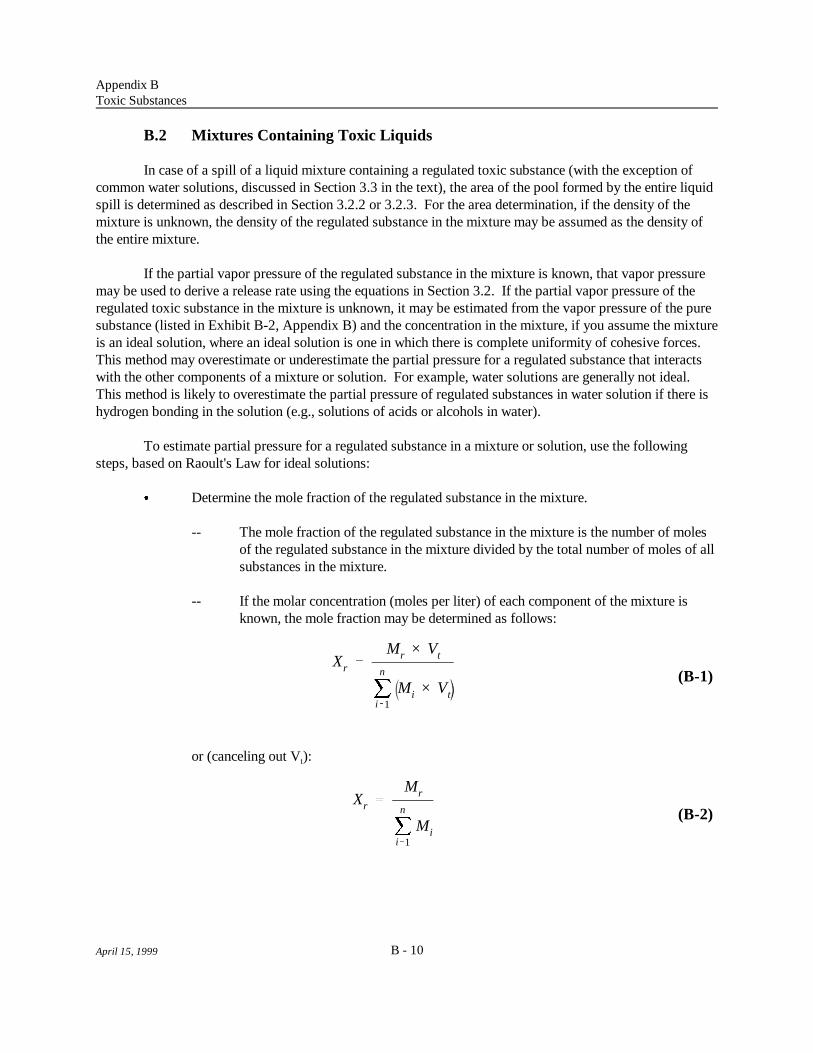
Xr Mr × Vt
Mn
i1
Mi × Vt
Xr Mr
Mn
i1
Mi
Appendix BToxic Substances
B - 10April 15, 1999
(B-1)
(B-2)
B.2 Mixtures Containing Toxic Liquids
In case of a spill of a liquid mixture containing a regulated toxic substance (with the exception ofcommon water solutions, discussed in Section 3.3 in the text), the area of the pool formed by the entire liquidspill is determined as described in Section 3.2.2 or 3.2.3. For the area determination, if the density of themixture is unknown, the density of the regulated substance in the mixture may be assumed as the density ofthe entire mixture.
If the partial vapor pressure of the regulated substance in the mixture is known, that vapor pressuremay be used to derive a release rate using the equations in Section 3.2. If the partial vapor pressure of theregulated toxic substance in the mixture is unknown, it may be estimated from the vapor pressure of the puresubstance (listed in Exhibit B-2, Appendix B) and the concentration in the mixture, if you assume the mixtureis an ideal solution, where an ideal solution is one in which there is complete uniformity of cohesive forces. This method may overestimate or underestimate the partial pressure for a regulated substance that interactswith the other components of a mixture or solution. For example, water solutions are generally not ideal. This method is likely to overestimate the partial pressure of regulated substances in water solution if there ishydrogen bonding in the solution (e.g., solutions of acids or alcohols in water).
To estimate partial pressure for a regulated substance in a mixture or solution, use the followingsteps, based on Raoult's Law for ideal solutions:
& Determine the mole fraction of the regulated substance in the mixture.
-- The mole fraction of the regulated substance in the mixture is the number of molesof the regulated substance in the mixture divided by the total number of moles of allsubstances in the mixture.
-- If the molar concentration (moles per liter) of each component of the mixture isknown, the mole fraction may be determined as follows:
or (canceling out V ):t

Xr Mr
Mr � M2 � M3
Xr
Wr
MWr
Mn
i1
Wi
MWi
Xr
Wr
MWr
Wr
MWr
�
W2
MW2
�
W3
MW3
Appendix BToxic Substances
B - 11April 15, 1999
(B-3)
(B-4)
(B-5)
where: X = Mole fraction of regulated substance in mixture (unitless)r
M = Molar concentration of regulated substance in mixture (moles per liter)r
V = Total volume of mixture (liters)t
n = Number of components of mixture M = Molar concentration of each component of mixture (moles per liter)i
For a mixture with three components, this would correspond to:
where: X = Mole fraction of regulated substance in mixture (unitless)r
M = Molar concentration of regulated substance (first component) in mixturer
(moles per liter)M = Molar concentration of second component of mixture (moles per liter)2
M = Molar concentration of any other components of mixture (moles per liter)3
-- If the weight of each of the components of the mixture is known, the mole fractionof the regulated substance in the mixture may be calculated as follows:
where: X = Mole fraction of the regulated substancer
W = Weight of the regulated substancer
MW = Molecular weight of the regulated substancer
n = Number of components of the mixture W = Weight of each component of the mixturei
MW = Molecular weight of each component of the mixturei
(Note: Weights can be in any consistent units.)
For a mixture with three components, this corresponds to:

VPm Xr × VPp
QR
0.0035 ×U 0.78 × MW2/3 × A × VPT
Appendix BToxic Substances
B - 12April 15, 1999
(B-6)
(B-7)
where: X = Mole fraction of the regulated substancer
W = Weight of the regulated substance (first component of the mixture)r
MW = Molecular weight of the regulated substancer
W = Weight of the second component of the mixture2
MW = Molecular weight of the second component of the mixture2
W = Weight of the third component of the mixture3
MW = Molecular weight of the third component of the mixture 3
(Note: Weights can be in any consistent units.)
& Estimate the partial vapor pressure of the regulated substance in the mixture as follows:
where: VP = Partial vapor pressure of the regulated substance in the mixture (millimetersm
of mercury (mm Hg))X = Mole fraction of the regulated substance (unitless)r
VP = Vapor pressure of the regulated substance in pure form at the samep
temperature as the mixture (mm Hg) (vapor pressure at 25 C is given ino
Exhibit B-1, Appendix B)
The evaporation rate for the regulated substance in the mixture is determined as for pure substances,with VP as the vapor pressure. If the mixture contains more than one regulated toxic substance, carry outm
the analysis individually for each of the regulated components. The release rate equation is:
where: QR = Evaporation rate (pounds per minute)U = Wind speed (meters per second)MW = Molecular weight (given in Exhibit B-2, Appendix B)A = Surface area of pool formed by the entire quantity of the mixture (square
feet) (determined as described in 3.2.2)VP = Vapor pressure (mm Hg) (VP from Equation B-4 above)m
T = Temperature (Kelvin (K); temperature in C plus 273, or 298 for 25 C)o o
See Appendix D, Section D.2.1 for more discussion of the evaporation rate equation. Equation B-7is derived from Equation D-1.
Worst-case consequence distances to the toxic endpoint may be estimated from the release rate usingthe tables and instructions presented in Chapter 4.

April 15, 1999
APPENDIX C
FLAMMABLE SUBSTANCES

D 17 × 0.1 × Wf ×HCf
HCTNT
1/3
Dmi 0.0081 × 0.1 × Wlb ×HCf
HCTNT
1/3
April 15, 1999
(C-1)
(C-2)
APPENDIX C FLAMMABLE SUBSTANCES
C.1 Equation for Estimation of Distance to 1 psi Overpressure for Vapor CloudExplosions
For a worst-case release of flammable gases and volatile flammable liquids, the release rate is notconsidered. The total quantity of the flammable substance is assumed to form a vapor cloud. The entirecontents of the cloud is assumed to be within the flammability limits, and the cloud is assumed to explode. For the worst-case, analysis, 10 percent of the flammable vapor in the cloud is assumed to participate in theexplosion (i.e., the yield factor is 0.10). Consequence distances to an overpressure level of 1 pound persquare inch (psi) may be determined using the following equation, which is based on the TNT-equivalencymethod:
where: D = Distance to overpressure of 1 psi (meters)W = Weight of flammable substance (kilograms or pounds/2.2)f
Hc = Heat of combustion of flammable substance (kilojoules per kilogram)f
(listed in Exhibit C-1)HC = Heat of explosion of trinitrotoluene (TNT) (4,680 kilojoules per kilogram)TNT
The factor 17 is a constant for damages associated with 1.0 psi overpressures. The factor 0.1represents an explosion efficiency of 10 percent. To convert distances from meters to miles, multiplyby 0.00062.
Alternatively, use the following equation for quantity in pounds and distance in miles:
where: D = Distance to overpressure of 1 psi (miles)mi
W = Weight of flammable substance (pounds)lb
These equations were used to derive Reference Table 13 for worst-case distances to the overpressureendpoint (1 psi) for vapor cloud explosions.
C.2 Mixtures of Flammable Substances
For a mixture of flammable substances, you may estimate the heat of combustion of the mixture fromthe heats of combustion of the components of the mixture using the equation below and then use the equationgiven in the previous section of this appendix to determine the vapor cloud explosion distance. The heat ofcombustion of the mixture may be estimated as follows:

HCm
Wx
Wm
× HCx �Wy
Wm
× HCy
Appendix CFlammable Substances
C - 2April 15, 1999
(C-3)
where: HC = Heat of combustion of mixture (kilojoules per kilogram)m
W = Weight of component "X" in mixture (kilograms or pounds/2.2)x
W = Total weight of mixture (kilograms or pounds/2.2)m
HC = Heat of combustion of component "X" (kilojoules per kilogram)x
W = Weight of component "Y" in mixture (kilograms or pounds/2.2)y
HC = Heat of combustion of component "Y" (kilojoules per kilogram)y
Heats of combustion for regulated flammable substances are listed in Exhibit C-1 in the next section(Section C.3) of this appendix.
C.3 Data for Flammable Substances
The exhibits in this section of Appendix C provide the data needed to carry out the calculations forregulated flammable substances using the methods presented in the text of this guidance. Exhibit C-1presents heat of combustion data for all regulated flammable substances, Exhibit C-2 presents additional datafor flammable gases, and Exhibit C-3 presents additional data for flammable liquids. The heats ofcombustion in Exhibit C-1 and the data used to develop the factors in Exhibits C-2 and C-3 are primarilyfrom Design Institute for Physical Property Data, American Institute of Chemical Engineers, Physical andThermodynamic Properties of Pure Chemicals, Data Compilation. The derivation of the factors presentedin Exhibits C-2 and C-3 is discussed in Appendix D.

C - 3April 15, 1999
Exhibit C-1Heats of Combustion for Flammable Substances
CAS No. Chemical Name State CombustionPhysical Heat of
at 25 C (kjoule/kg)o
75-07-0 Acetaldehyde Gas 25,072
74-86-2 Acetylene [Ethyne] Gas 48,222
598-73-2 Bromotrifluoroethylene [Ethene, bromotrifluoro-] Gas 1,967
106-99-0 1,3-Butadiene Gas 44,548
106-97-8 Butane Gas 45,719
25167-67-3 Butene Gas 45,200*
590-18-1 2-Butene-cis Gas 45,171
624-64-6 2-Butene-trans [2-Butene, (E)] Gas 45,069
106-98-9 1-Butene Gas 45,292
107-01-7 2-Butene Gas 45,100*
463-58-1 Carbon oxysulfide [Carbon oxide sulfide (COS)] Gas 9,126
7791-21-1 Chlorine monoxide [Chlorine oxide] Gas 1,011*
590-21-6 1-Chloropropylene [1-Propene, 1-chloro-] Liquid 23,000*
557-98-2 2-Chloropropylene [1-Propene, 2-chloro-] Gas 22,999
460-19-5 Cyanogen [Ethanedinitrile] Gas 21,064
75-19-4 Cyclopropane Gas 46,560
4109-96-0 Dichlorosilane [Silane, dichloro-] Gas 8,225
75-37-6 Difluoroethane [Ethane, 1,1-difluoro-] Gas 11,484
124-40-3 Dimethylamine [Methanamine, N-methyl-] Gas 35,813
463-82-1 2,2-Dimethylpropane [Propane, 2,2-dimethyl-] Gas 45,051
74-84-0 Ethane Gas 47,509
107-00-6 Ethyl acetylene [1-Butyne] Gas 45,565
75-04-7 Ethylamine [Ethanamine] Gas 35,210
75-00-3 Ethyl chloride [Ethane, chloro-] Gas 19,917
74-85-1 Ethylene [Ethene] Gas 47,145

Exhibit C-1 (continued)
CAS No. Chemical Name State CombustionPhysical Heat of
at 25 C (kjoule/kg)o
C - 4April 15, 1999
60-29-7 Ethyl ether [Ethane, 1,1'-oxybis-] Liquid 33,775
75-08-1 Ethyl mercaptan [Ethanethiol] Liquid 27,948
109-95-5 Ethyl nitrite [Nitrous acid, ethyl ester] Gas 18,000
1333-74-0 Hydrogen Gas 119,950
75-28-5 Isobutane [Propane, 2-methyl] Gas 45,576
78-78-4 Isopentane [Butane, 2-methyl-] Liquid 44,911
78-79-5 Isoprene [1,3-Butadiene, 2-methyl-] Liquid 43,809
75-31-0 Isopropylamine [2-Propanamine] Liquid 36,484
75-29-6 Isopropyl chloride [Propane, 2-chloro-] Liquid 23,720
74-82-8 Methane Gas 50,029
74-89-5 Methylamine [Methanamine] Gas 31,396
563-45-1 3-Methyl-1-butene Gas 44,559
563-46-2 2-Methyl-1-butene Liquid 44,414
115-10-6 Methyl ether [Methane, oxybis-] Gas 28,835
107-31-3 Methyl formate [Formic acid, methyl ester] Liquid 15,335
115-11-7 2-Methylpropene [1-Propene, 2-methyl-] Gas 44,985
504-60-9 1,3-Pentadiene Liquid 43,834
109-66-0 Pentane Liquid 44,697
109-67-1 1-Pentene Liquid 44,625
646-04-8 2-Pentene, (E)- Liquid 44,458
627-20-3 2-Pentene, (Z)- Liquid 44,520
463-49-0 Propadiene [1,2-Propadiene] Gas 46,332
74-98-6 Propane Gas 46,333
115-07-1 Propylene [1-Propene] Gas 45,762
74-99-7 Propyne [1-Propyne] Gas 46,165
7803-62-5 Silane Gas 44,307

Exhibit C-1 (continued)
CAS No. Chemical Name State CombustionPhysical Heat of
at 25 C (kjoule/kg)o
C - 5April 15, 1999
116-14-3 Tetrafluoroethylene [Ethene, tetrafluoro-] Gas 1,284
75-76-3 Tetramethylsilane [Silane, tetramethyl-] Liquid 41,712
10025-78-2 Trichlorosilane [Silane, trichloro-] Liquid 3,754
79-38-9 Trifluorochloroethylene [Ethene, chlorotrifluoro-] Gas 1,837
75-50-3 Trimethylamine [Methanamine, N,N-dimethyl-] Gas 37,978
689-97-4 Vinyl acetylene [1-Buten-3-yne] Gas 45,357
75-01-4 Vinyl chloride [Ethene, chloro-] Gas 18,848
109-92-2 Vinyl ethyl ether [Ethene, ethoxy-] Liquid 32,909
75-02-5 Vinyl fluoride [Ethene, fluoro-] Gas 2,195
75-35-4 Vinylidene chloride [Ethene, 1,1-dichloro-] Liquid 10,354
75-38-7 Vinylidene fluoride [Ethene, 1,1-difluoro-] Gas 10,807
107-25-5 Vinyl methyl ether [Ethene, methoxy-] Gas 30,549
Estimated heat of combustion*

C - 6April 15, 1999
Exhibit C-2Data for Flammable Gases
CAS Molecular Specific Limits (Vol %) LFL Factor Factor Factor Reference Factor FractionNumber Chemical Name Weight Heats (mg/L) (GF) Boilin g (Boiling) Table (PFF) Factor
Ratio of Flammabilit y Gas Liquid Density Pool Fire Flash
g
(LFB) (DF) (FFF)
a
fLower Upper(LFL) UFL
75-07-0 Acetaldehyde 44.05 1.18 4.0 60.0 72 22 0.11 0.62 Dense 2.7 0.018
74-86-2 Acetylene 26.04 1.23 2.5 80.0 27 17 0.12 0.78 Buoyant 4.8 0.23b f
598-73-2 Bromotrifluoroethylene 160.92 1.11 37.0 41 0.25 0.29 Dense 0.42 0.15c c c c c c c
106-99-0 1,3-Butadiene 54.09 1.12 2.0 11.5 44 24 0.14 0.75 Dense 5.5 0.15
106-97-8 Butane 58.12 1.09 1.5 9.0 36 25 0.14 0.81 Dense 5.9 0.15
25167-67-3 Butene 56.11 1.10 1.7 9.5 39 24 0.14 0.77 Dense 5.6 0.14
590-18-1 2-Butene-cis 56.11 1.12 1.6 9.7 37 24 0.14 0.76 Dense 5.6 0.11
624-64-6 2-Butene-trans 56.11 1.11 1.8 9.7 41 24 0.14 0.77 Dense 5.6 0.12
106-98-9 1-Butene 56.11 1.11 1.6 9.3 37 24 0.14 0.78 Dense 5.7 0.17
107-01-7 2-Butene 56.11 1.10 1.7 9.7 39 24 0.14 0.77 Dense 5.6 0.12
463-58-1 Carbon oxysulfide 60.08 1.25 12.0 29.0 290 26 0.18 0.41 Dense 1.3 0.29
7791-21-1 Chlorine monoxide 86.91 1.21 23.5 NA 830 31 0.19 NA Dense 0.15 NA
557-98-2 2-Chloropropylene 76.53 1.12 4.5 16.0 140 29 0.16 0.54 Dense 3.3 0.011
460-19-5 Cyanogen 52.04 1.17 6.0 32.0 130 24 0.15 0.51 Dense 2.5 0.40
75-19-4 Cyclopropane 42.08 1.18 2.4 10.4 41 22 0.13 0.72 Dense 5.4 0.23
4109-96-0 Dichlorosilane 101.01 1.16 4.0 96.0 160 33 0.20 0.40 Dense 1.3 0.084
75-37-6 Difluoroethane 66.05 1.14 3.7 18.0 100 27 0.17 0.48 Dense 1.6 0.23
124-40-3 Dimethylamine 45.08 1.14 2.8 14.4 52 22 0.12 0.73 Dense 3.7 0.090
463-82-1 2,2-Dimethylpropane 72.15 1.07 1.4 7.5 41 27 0.16 0.80 Dense 6.4 0.11
74-84-0 Ethane 30.07 1.19 2.9 13.0 36 18 0.14 0.89 Dense 5.4 0.75
107-00-6 Ethyl acetylene 54.09 1.11 2.0 32.9 44 24 0.13 0.73 Dense 5.4 0.091
75-04-7 Ethylamine 45.08 1.13 3.5 14.0 64 22 0.12 0.71 Dense 3.6 0.040

Exhibit C-2 (continued)
CAS Molecular Specific Limits (Vol %) LFL Factor Factor Factor Reference Factor FractionNumber Chemical Name Weight Heats (mg/L) (GF) Boilin g (Boiling) Table (PFF) Factor
Ratio of Flammabilit y Gas Liquid Density Pool Fire Flash
g
(LFB) (DF) (FFF)
a
fLower Upper(LFL) UFL
C - 7April 15, 1999
75-00-3 Ethyl chloride 64.51 1.15 3.8 15.4 100 27 0.15 0.53 Dense 2.6 0.053
74-85-1 Ethylene 28.05 1.24 2.7 36.0 31 18 0.14 0.85 Buoyant 5.4 0.63b f
109-95-5 Ethyl nitrite 75.07 1.30 4.0 50.0 120 30 0.16 0.54 Dense 2.0 NA
1333-74-0 Hydrogen 2.02 1.41 4.0 75.0 3.3 5.0 NAe e d e
75-28-5 Isobutane 58.12 1.09 1.8 8.4 43 25 0.15 0.82 Dense 6.0 0.23
74-82-8 Methane 16.04 1.30 5.0 15.0 33 14 0.15 1.1 Buoyant 5.6 0.87f
74-89-5 Methylamine 31.06 1.19 4.9 20.7 62 19 0.10 0.70 Dense 2.7 0.12
563-45-1 3-Methyl-1-butene 70.13 1.08 1.5 9.1 43 26 0.15 0.77 Dense 6.0 0.030
115-10-6 Methyl ether 46.07 1.15 3.3 27.3 64 22 0.14 0.66 Dense 3.4 0.22
115-11-7 2-Methylpropene 56.11 1.10 1.8 8.8 41 24 0.14 0.77 Dense 5.7 0.18
463-49-0 Propadiene 40.07 1.16 2.1 2.1 34 21 0.13 0.73 Dense 5.2 0.20
74-98-6 Propane 44.10 1.13 2.0 9.5 36 22 0.14 0.83 Dense 5.7 0.38
115-07-1 Propylene 42.08 1.15 2.0 11.0 34 21 0.14 0.79 Dense 5.5 0.35
74-99-7 Propyne 40.07 1.16 1.7 39.9 28 21 0.12 0.72 Dense 4.9 0.18
7803-62-5 Silane 32.12 1.24 19 Dense 0.41c c c c e e e f
116-14-3 Tetrafluoroethylene 100.02 1.12 11.0 60.0 450 33 0.29 0.32 Dense 0.25 0.69
79-38-9 Trifluorochloroethylene 116.47 1.11 8.4 38.7 400 35 0.26 0.33 Dense 0.34 0.27
75-50-3 Trimethylamine 59.11 1.10 2.0 11.6 48 25 0.14 0.74 Dense 4.8 0.12
689-97-4 Vinyl acetylene 52.08 1.13 2.2 31.7 47 24 0.13 0.69 Dense 5.4 0.086
75-01-4 Vinyl chloride 62.50 1.18 3.6 33.0 92 26 0.16 0.50 Dense 2.4 0.14
75-02-5 Vinyl fluoride 46.04 1.20 2.6 21.7 49 23 0.17 0.57 Dense 0.28 0.37
75-38-7 Vinylidene fluoride 64.04 1.16 5.5 21.3 140 27 0.22 0.42 Dense 1.8 0.50

Exhibit C-2 (continued)
CAS Molecular Specific Limits (Vol %) LFL Factor Factor Factor Reference Factor FractionNumber Chemical Name Weight Heats (mg/L) (GF) Boilin g (Boiling) Table (PFF) Factor
Ratio of Flammabilit y Gas Liquid Density Pool Fire Flash
g
(LFB) (DF) (FFF)
a
fLower Upper(LFL) UFL
C - 8April 15, 1999
107-25-5 Vinyl methyl ether 58.08 1.12 2.6 39.0 62 25 0.17 0.57 Dense 3.7 0.093
Notes:
NA: Data not available "Buoyant" in the Reference Table column refers to the tables for neutrally buoyant gases and vapors; "Dense" refers to the tables for dense gases and vapors. Seea
Appendix D, Section D.4.4, for more information on the choice of reference tables. Gases that are lighter than air may behave as dense gases upon release if liquefied under pressure or cold; consider the conditions of release when choosing theb
appropriate table. Reported to be spontaneously combustible.c
Much lighter than air; table of distances for neutrally buoyant gases not appropriate.d
Pool formation unlikely.e
Calculated at 298 K (25 C) with the following exceptions:f o
Acetylene factor at 250 K as reported in TNO, Methods for the Calculation of the Physical Effects of the Escape of Dangerous Material (1980).Ethylene factor calculated at critical temperature, 282 K.Methane factor calculated at critical temperature, 191 K.Silane factor calculated at critical temperature, 270 K.
Use GF for gas leaks under choked (maximum) flow conditions. g

C - 9April 15, 1999
Exhibit C-3Data for Flammable Liquids
CAS Chemical Name Molecular (Vol%) (mg/L) Factor Factor Table FactorNumber Weight (LLF) (PFF)
Flammabilit y Limit LFL Li quid Factors Density Li quid Leak Reference Pool Fire
a
b
Lower Upper Ambient Boilin g(LFL) (UFL) (LFA) (LFB)
590-21-6 1-Chloropropylene 76.53 4.5 16.0 140 0.11 0.15 0.52 45 Dense 3.2
60-29-7 Ethyl ether 74.12 1.9 48.0 57 0.11 0.15 0.69 34 Dense 4.3
75-08-1 Ethyl mercaptan 62.14 2.8 18.0 71 0.10 0.13 0.58 40 Dense 3.3
78-78-4 Isopentane 72.15 1.4 7.6 41 0.14 0.15 0.79 30 Dense 6.1
78-79-5 Isoprene 68.12 2.0 9.0 56 0.11 0.14 0.72 32 Dense 5.5
75-31-0 Isopropylamine 59.11 2.0 10.4 48 0.10 0.13 0.71 33 Dense 4.1
75-29-6 Isopropyl chloride 78.54 2.8 10.7 90 0.11 0.16 0.57 41 Dense 3.1
563-46-2 2-Methyl-1-butene 70.13 1.4 9.6 40 0.12 0.15 0.75 31 Dense 5.8
107-31-3 Methyl formate 60.05 5.9 20.0 140 0.10 0.13 0.50 46 Dense 1.8
504-60-9 1,3-Pentadiene 68.12 1.6 13.1 44 0.077 0.14 0.72 33 Dense 5.3
109-66-0 Pentane 72.15 1.3 8.0 38 0.10 0.15 0.78 30 Dense 5.8
109-67-1 1-Pentene 70.13 1.5 8.7 43 0.13 0.15 0.77 31 Dense 5.8
646-04-8 2-Pentene, (E)- 70.13 1.4 10.6 40 0.10 0.15 0.76 31 Dense 5.6
627-20-3 2-Pentene, (Z)- 70.13 1.4 10.6 40 0.10 0.15 0.75 31 Dense 5.6
75-76-3 Tetramethylsilane 88.23 1.5 NA 54 0.17 0.17 0.59 40 Dense 6.3
10025-78-2 Trichlorosilane 135.45 1.2 90.5 66 0.18 0.23 0.37 64 Dense 0.68
109-92-2 Vinyl ethyl ether 72.11 1.7 28.0 50 0.10 0.15 0.65 36 Dense 4.2
75-35-4 Vinylidene chloride 96.94 7.3 NA 290 0.15 0.18 0.44 54 Dense 1.6
Notes:
NA: Data not available. Use the LLF only for leaks from tanks at atmospheric pressure.a
"Dense" in the Reference Table column refers to the tables for dense gases and vapors. See Appendix D, Section D.4.4, for more information on the choice ofb
reference tables.

April 15, 1999
APPENDIX D
TECHNICAL BACKGROUND

April 15, 1999
APPENDIX D TECHNICAL BACKGROUND
D.1 Worst-Case Release Rate for Gases
D.1.1 Unmitigated Release
The assumption that the total quantity of toxic gas is released in 10 minutes is the same assumptionused in EPA's Technical Guidance for Hazards Analysis (1987).
D.1.2 Gaseous Release Inside Building
The mitigation factor for gaseous release inside a building is based on a document entitled, RiskMitigation in Land Use Planning: Indoor Releases of Toxic Gases, by S.R. Porter. This paper presentedthree release scenarios and discussed the mitigating effects that would occur in a building with a volume of1,000 cubic meters at three different building air exchange rates. There is a concern that a building may notbe able to withstand the pressures of a very large release. However, this paper indicated that release rates ofat least 2,000 pounds per minute could be withstood by a building.
Analyzing the data in this paper several ways, the value of 55 percent emerged as representing themitigation that could occur for a release scenario into a building. Data are provided on the maximum releaserate in a building and the maximum release rate from a building. Making this direct comparison at the lowermaximum release rate (3.36 kg/s) gave a release rate from the building of 55 percent of the release rate intothe building. Using information provided on another maximum release rate (10.9 kg/min) and accounting forthe time for the release to accumulate in the building, approximately 55 percent emerged again.
The choice of building ventilation rates affects the results. The paper presented mitigation for threedifferent ventilation rates, 0.5, 3, and 10 air changes per hour. A ventilation rate of 0.5 changes per hour isrepresentative of specially designed, “gas-tight” buildings, based on the Porter reference. EPA decided thatthis ventilation rate was appropriate for this analysis. A mitigation factor of 55 percent may be used in theevent of a gaseous release which does not destroy the building into which it is released. This factor mayoverstate the mitigation provided by a building with a higher ventilation rate.
For releases of ammonia, chlorine, and sulfur dioxide, factors specific to the chemicals, theconditions of the release, and building ventilation rates have been developed to estimate mitigation of releasesin buildings. For information on these factors and estimation of mitigated release rates, see BackupInformation for the Hazard Assessments in the RMP Offsite Consequence Analysis Guidance, theGuidance for Wastewater Treatment Facilities and the Guidance for Ammonia Refrigeration - AnhydrousAmmonia, Aqueous Ammonia, Chlorine and Sulfur Dioxide. See also the industry-specific guidancedocuments for ammonia refrigeration and POTWs.
D.2 Worst-Case Release Rate for Liquids
D.2.1 Evaporation Rate Equation
The equation for estimating the evaporation rate of a liquid from a pool is from the TechnicalGuidance for Hazards Analysis, Appendix G. The same assumptions are made for determination of

QR
0.284 × U 0.78 × MW2/3 × A × VP82.05 × T
LFA
0.284 × MW2/3 × VP82.05 × 298
Appendix DTechnical Background
D - 2April 15, 1999
(D-1)
(D-2)
maximum pool area (i.e., the pool is assumed to be 1 centimeter (0.033 feet) deep). The evaporation rateequation has been modified to include a different mass transfer coefficient for water, the reference compound. For this document, a value of 0.67 centimeters per second is used as the mass transfer coefficient, instead ofthe value of 0.24 cited in the Technical Guidance for Hazards Analysis. The value of 0.67 is based onDonald MacKay and Ronald S. Matsugu, "Evaporation Rates of Liquid Hydrocarbon Spills on Land andWater," Canadian Journal of Chemical Engineering, August 1973, p. 434. The evaporation equationbecomes:
where: QR = Evaporation rate (pounds per minute)U = Wind speed (meters per second)MW = Molecular weight (given in Exhibits B-1 and B-2, Appendix B, for toxic
substances and Exhibits C-2 and C-3, Appendix C, for flammablesubstances)
A = Surface area of pool formed by the entire quantity of the mixture (squarefeet) (determined as described in Section 3.2.2 of the text)
VP = Vapor pressure (mm Hg)T = Temperature of released substance (Kelvin (K); temperature in C plus 273,o
or 298 for 25 C)o
D.2.2 Factors for Evaporation Rate Estimates
Liquid Factors. The liquid factors, Liquid Factor Ambient (LFA) and Liquid Factor Boiling (LFB),used to estimate the evaporation rate from a liquid pool (see Section 3.2 of this guidance document), arederived as described in the Technical Guidance for Hazards Analysis, Appendix G, with the followingdifferences:
& The mass transfer coefficient of water is assumed to be 0.67, as discussed above; the valueof the factor that includes conversion factors, the mass transfer coefficient for water, and themolecular weight of water to the one-third power, given as 0.106 in the Technical Guidanceis 0.284 in this guidance.
& Density of all substances was assumed to be the density of water in the Technical Guidance;the density was included in the liquid factors. For this guidance document, density is notincluded in the LFA and LFB values presented in the tables; instead, a separate DensityFactor (DF) (discussed below) is provided to be used in the evaporation rate estimation.
With these modifications, the LFA is:
where: MW = Molecular weight

LFB
0.284 × MW2/3 × 76082.05 × BP
DF
1d × 0.033
TCFT
VPT × 298
VP298 × T
Appendix DTechnical Background
D - 3April 15, 1999
(D-3)
(D-4)
(D-5)
VP = Vapor pressure at ambient temperature (mm Hg)298 K (25 C) = Ambient temperature and temperature of released substanceo
LFB is:
where: MW = Molecular weight760 = Vapor pressure at boiling temperature (mm Hg)BP = Boiling point (K)
LFA and LFB values were developed for all toxic and flammable regulated liquids, and LFB values,to be used for analysis of gases liquefied by refrigeration, were developed for toxic and flammable gases.
Density Factor. Because some of the regulated liquids have densities very different from that ofwater, the density of each substance was used to develop a Density Factor (DF) for the determination ofmaximum pool area for the evaporation rate estimation. DF values were developed for toxic and flammableliquids at ambient temperature and for toxic and flammable gases at their boiling points. The density factoris:
where: DF = Density factor (1/(lbs/ft ))2
d = Density of the substance in pounds per cubic foot0.033 = Depth of pool for maximum area (feet)
Temperature Correction Factors. Temperature correction factors were developed for toxic liquidsreleased at temperatures above 25 C, the temperature used for development of the LFAs. The temperatureo
correction factors are based on vapor pressures calculated from the coefficients provided in Physical andThermodynamic Properties of Pure Chemicals, Data Compilation, developed by the Design Institute forPhysical Property Data (DIPPR), American Institute of Chemical Engineers. The factors are calculated asfollows:
where: TCF = Temperature Correction Factor at temperature TT
VP = Vapor pressure at temperature TT
VP = Vapor pressure at 298 K298
T = Temperature (K) of released substance
Factors were developed at intervals of 5 C for temperatures up to 50 C. o o

Appendix DTechnical Background
D - 4April 15, 1999
No correction factor was deemed necessary for changes in the density of the regulated toxic liquidswith changes in temperature, although the density could affect the pool area and release rate estimates. Analysis of the temperature dependence of the density of these liquids indicated that the changes in densitywith temperature were very small compared to the changes in vapor pressure with temperature.
D.2.3 Common Water Solutions and Oleum
Water solutions of regulated toxic substances must be analyzed somewhat differently from pure toxicliquids. Except for solutions of relatively low concentration, the evaporation rate varies with theconcentration of the solution. At one specific concentration, the composition of the liquid does not change asevaporation occurs. For concentrated solutions of volatile substances, the evaporation rate from a pool maydecrease, very rapidly in some cases, as the toxic substance volatilizes and its concentration in the pooldecreases. To analyze these changes, EPA used spreadsheets to estimate the vapor pressure, concentration,and release rate at various time intervals for regulated toxic substances in water solution evaporating frompools. In addition to the spreadsheet analysis, EPA used the ALOHA model with an additional step-functionfeature (not available in the public version). With this step-function feature, changes in the release rate couldbe incorporated and the effects of these changes on the consequence distance analyzed. The results of thespreadsheet calculations and the model were found to be in good agreement. The distance results obtainedfrom the spreadsheet analysis and the model for various solutions were compared with the results fromvarious time averages to examine the sensitivity of the results. An averaging time of 10 minutes was found togive reasonable agreement with the step-function model for most substances at various concentrations. Thespreadsheet analysis also indicated that the first 10 minutes of evaporation was the most important, and theevaporation rate in the first 10 minutes likely could be used to estimate the distance to the endpoint.
Oleum is a solution of sulfur trioxide in sulfuric acid. Sulfur trioxide evaporating from oleumexhibits release characteristics similar to those of toxic substances evaporating from water solutions. Analysis of oleum releases, therefore, was carried out in the same way as for water solutions.
NOAA developed a computerized calculation method to estimate partial vapor pressures and releaserates for regulated toxic substance in solution as a function of concentration, based on vapor pressure datafrom Perry's Chemical Engineers' Handbook and other sources. Using this method and spreadsheetcalculations, EPA estimated partial vapor pressures and evaporation rates at one-minute intervals over 10minutes for solutions of various concentrations. The 10-minute time period was chosen based on theALOHA results and other calculations. For each one-minute interval, EPA estimated the concentration of thesolution based on the quantity evaporated in the previous interval and estimated the partial vapor pressurebased on the concentration. These estimated vapor pressures were used to calculate an average vaporpressure over the 10-minute period; this average vapor pressure was used to derive Liquid Factor Ambient(LFA) values, as described above for liquids. Use of these factors is intended to give an evaporation rate thataccounts for the decrease in evaporation rate expected to take place as the solution evaporates.
Density Factors (DF) were developed for solutions of various concentrations from data in Perry'sChemical Engineers' Handbook and other sources, as discussed above for liquids.
Because solutions do not have defined boiling points, EPA did not develop Liquid Factor Boiling(LFB) values for solutions. As a simple and conservative approach, the quantity of a regulated substance in asolution at an elevated temperatures is treated as a pure substance. The LFB for the pure substance, or the

QR U 0.78 × (LFA, LFB) × A
Appendix DTechnical Background
D - 5April 15, 1999
(D-6)
LFA and a temperature correction factor, is used to estimate the initial evaporation rate of the regulatedsubstance from the solution. Only the first 10 minutes of evaporation are considered, as for solutions atambient temperatures, because the release rate would decrease rapidly as the substance evaporates and theconcentration in the solution decreases. This approach will likely give an overestimate of the release rate andof the consequence distance.
D.2.4 Releases Inside Buildings
If a liquid is released inside a building, its release to the outside air will be mitigated in two ways. First, the evaporation rate of the liquid may be much lower inside a building than outside. This is due to windspeed, which directly affects the evaporation rate. The second mitigating factor is that the building providesresistance to discharge of contaminated air to the outdoors.
In this method, a conservative wind speed, U, of 0.1 meter per second (m/s) was assumed in thebuilding. (See end of text for a justification of this wind speed.) For a release outdoors in a worst-casescenario, U is set to 1.5 m/s, and for an alternative scenario, U is set to 3 m/s. The evaporation rate equationis:
where: QR = Release rate (pounds per minute (lbs/min))U = Wind speed (meters per second (m/s))LFA = Liquid Factor AmbientLFB = Liquid Factor BoilingA = Area of pool (square feet (ft ))2
As can be seen, if U inside a building is only 0.1, then the evaporation rate inside a building will be muchlower than a corresponding evaporation rate outside (assuming the temperature is the same). The rate willonly be (0.1/1.5) , about 12 percent of the rate for a worst case, and (0.1/3) , about seven percent of the0.78 0.78
rate for an alternative case.
The evaporated liquid mixes with and contaminates the air in the building. What EPA is ultimatelyinterested in is the rate at which this contaminated air exits the building. In order to calculate the release ofcontaminated air outside the building, EPA adapted a method from an UK Health and Safety Executive paperentitled, Risk Mitigation in Land Use Planning: Indoor Releases of Toxic Gases, by S.R. Porter. EPAassumed that the time for complete evaporation of the liquid pool was one hour. The rate at whichcontaminated air was released from the building during liquid evaporation (based on the paper) was assumedto be equal to the evaporation rate plus the building ventilation rate (no pressure buildup in building). Thebuilding ventilation rate was set equal to 0.5 air changes per hour. This ventilation rate is representative of aspecially designed, “gas-tight” building. (The mitigation factor developed based on this type of buildingwould overstate the mitigation provided by a building with higher ventilation rates.) EPA used a buildingwith a volume of 1,000 cubic meters (m ) and a floor area of 200 m (2,152 ft ) as an example for this3 2 2
analysis. EPA assumed that the liquid pool would cover the entire building floor, representing a conservativescenario.

Appendix DTechnical Background
D - 6April 15, 1999
To provide a conservative estimate, EPA calculated the evaporation rate for a spill of a volatileliquid, carbon disulfide (CS ), under ambient conditions inside the building:2
QR = 0.1 × 0.075 × 2,152 = 26.8 pounds per minute (lbs/min)0.78
Next, this evaporation rate was converted to cubic meters per minute (m /min) using the ideal gas3
law (the molecular weight of CS is 76.1):2
26.8 lbs/min × 454 grams per pound (g/lb) × 1 mole CS/76.1 g × 0.0224 m /mole = 3.58 m /min.23 3
The ventilation rate of the building is 0.5 changes per hour, which equals 500 m per hour, or 8.333
m /min. Therefore, during evaporation, contaminated air is leaving the building at a rate of 8.33 + 3.58, or3
11.9 m /min. 3
EPA used an iterative calculation for carbon disulfide leaving a building using the above calculatedparameters. During the first minute of evaporation, 26.8 lbs of pure carbon disulfide evaporates, and EPAassumed this evenly disperses through the building so that the concentration of CS in the building air is2
0.0268 lbs/m (assuming 1000 m volume in the building). Contaminated air is exiting the building at a rate3 3
of 11.9 m /min, so EPA deduced that 11.9 × 0.0268 = 0.319 lbs of carbon disulfide exit the building in the3
first minute, leaving 26.5 lbs still evenly dispersed inside. Since this release occurs over one minute, therelease rate of the carbon disulfide to the outside is 0.319 lbs/min. During the second minute, another 26.8lbs of pure carbon disulfide evaporates and disperses, so that the building now contains 26.8 + 26.5 = 53.3lbs of carbon disulfide, or 0.0533 lbs/m . Contaminated air is still exiting the building at a rate of 11.93
m /min, so 11.9 × 0.05328 = 0.634 lbs of carbon disulfide are released, leaving 52.6 lbs inside. Again, this3
release occurs over one minute so that the rate of carbon disulfide exiting the building in terms ofcontaminated air is 0.634 lbs/min. EPA continued to perform this estimation over a period of one hour. Therate of release of carbon disulfide exiting the building in the contaminated air at the sixty minute mark is 13.7lbs/min. This represents the maximum rate of carbon disulfide leaving the building. After all of the carbondisulfide is evaporated, there is a drop in the concentration of carbon disulfide in the contaminated air leavingthe building because the evaporation of carbon disulfide no longer contributes to the overall contamination ofthe air.
Note that if the same size pool of carbon disulfide formed outside, the release rate for a worst-casescenario would be:
QR = 1.5 × 0.075 × 2,152 = 221 lbs/min.0.78
and for an alternative case:
QR = 3 × 0.075 × 2,152 = 380 lbs/min.0.78
The maximum release rate of carbon disulfide in the contaminated building air, assuming a 1,000 m3
building with a building exchange rate of 0.5 air changes per hour, was only about 6 percent (13.7 ÷ 221lbs/min x 100) of the worst-case scenario rate, and only about 3.6 percent (13.7 ÷ 380 lbs/min x 100) of thealternative scenario rate. EPA set an overall building mitigation factor equal to 10 percent and five percent,respectively, in order to be conservative. Please note that (at a constant ventilation rate of 0.5 changes per

Appendix DTechnical Background
D - 7April 15, 1999
hour) as the size of the building increases, the maximum rate of contaminated air leaving the building willdecrease, although only slightly, because of the balancing effect of building volume and ventilation rate. Obviously, a higher ventilation rate will yield a higher maximum release rate of contaminated air from thebuilding.
For a release inside a building, EPA assumed a building air velocity of 0.1 m/s. This conservativevalue was derived by setting the size of the ventilation fan equal to 1.0 m . This fan is exchanging air from2
the building with the outside at a rate of 0.5 changes per hour. For a 1,000 m building, this value becomes3
500 m /hour, or 0.14 m /s. Dividing 0.14 m /s by the area of the fan yields a velocity of 0.14 m/s, which was3 3 3
rounded down to 0.1 m/s.
D.3 Toxic Endpoints
The toxic endpoints for regulated toxic substances, which are specified in the RMP Rule, arepresented in Appendix B, Exhibits B-1, B-2, and B-3. The endpoints were chosen as follows, in order ofpreference:
(1) Emergency Response Planning Guideline 2 (ERPG-2), developed by the American IndustrialHygiene Association, if available;
(2) Level of Concern (LOC) derived for extremely hazardous substances (EHSs) regulatedunder section 302 of the Emergency Planning and Community Right-to-Know Act (EPCRA)(see the Technical Guidance for Hazards Analysis for more information on LOCs); theLOC for EHSs is based on:
-- One-tenth of the Immediately Dangerous to Life and Health (IDLH) level,developed by the National Institute of Occupational Safety and Health (NIOSH),using IDLH values developed before 1994,
or, if no IDLH value is available,
-- One-tenth of an estimated IDLH derived from toxicity data; the IDLH is estimatedas described in Appendix D of the Technical Guidance for Hazards Analysis.
Note that the LOCs were not updated using IDLHs published in 1994 and later,because NIOSH revised its methodology for the IDLHs. The EHS LOCs based onearlier IDLHs were reviewed by EPA’s Science Advisory Board, and EPA decidedto retain the methodology that was reviewed.
ERPG-2 is defined as the maximum airborne concentration below which it is believed nearly allindividuals could be exposed for up to one hour without experiencing or developing irreversible or otherserious health effects or symptoms that could impair an individual's ability to take protective action.
IDLH (pre-1994) concentrations were defined in the NIOSH Pocket Guide to Chemical Hazards asrepresenting the maximum concentration from which, in the event of respirator failure, one could escapewithin 30 minutes without a respirator and without experiencing any escape-impairing (e.g., severe eye

Appendix DTechnical Background
D - 8April 15, 1999
irritation) or irreversible health effects. (As noted above, LOCs for EHSs were not updated to reflect 1994and later IDLHs.)
The estimated IDLH is derived from animal toxicity data, in order of preferred data, as follows:
& From median lethal concentration (LC ) (inhalation): 0.1 x LC50 50
& From lowest lethal concentration (LC ) (inhalation): 1 x LCLO LO
& From median lethal dose (LD ) (oral): 0.01 x LD50 50
& From lowest lethal dose (LD ) (oral): 0.1 x LDLO LO
The toxic endpoints based on LOCs for EHSs presented in the tables in Appendix B are, in somecases, different from the LOCs listed in the Technical Guidance for Hazards Analysis, because some of theLOCs were updated based on IDLHs that were published after the development of the LOCs (and before1994) or on new or revised toxicity data.
D.4 Reference Tables for Distances to Toxic and Flammable Endpoints
D.4.1 Neutrally Buoyant Gases
Toxic Substances. Reference tables for distances to toxic endpoints for neutrally buoyant gases andvapors were derived from the Gaussian model using the longitudinal dispersion coefficients based on work byBeals (Guide to Local Diffusion of Air Pollutants, Technical Report 214. Scott Air Force Base, Illinois:U.S. Air Force, Air Weather Service, 1971). The reasons for using the Beals dispersion coefficients arediscussed below.
Longitudinal dispersion (dispersion in the along-wind direction) is generated mostly by vertical windshear. Wind shear results from the tendency of the wind speed to assume a wind profile—the speed is lowestnext to the ground and increases with height until it reaches an asymptotic value at approximately a fewhundred feet above the surface. To account for shear-driven dispersion, any air dispersion model intended formodeling short-duration releases must include either (a) a formulation that accounts, either implicitly orexplicitly, for the height-dependence of wind speed or (b) some type of parameterization that converts sheareffect into ) , the standard deviation function in the along-wind direction.x
Because the standard Gaussian formula does not incorporate ) (it includes only ) and ) , thex y z
crosswind and horizontal functions), very few alternate ways to formulate ) have been proposed. Thex
simplest method was proposed by Turner (Workbook of Atmospheric Dispersion Estimates, Report PB-191482. Research Triangle Park, North Carolina: Office of Air Programs, U.S. Environmental ProtectionAgency, 1970), who suggested simply setting ) equal to ) . Textbooks such as that by Pasquill and Smithx y
(Atmospheric Diffusion, 3rd ed. New York: Halstead Press, 1983) describe a well-known analytic model. However, this model is more complex than a Gaussian model because according to it, dispersion depends onwind shear and the vertical variation of the vertical diffusion coefficient. Wilson (Along-wind Diffusion ofSource Transients, Atmospheric Environment 15:489-495, 1981) proposed another method in which ) isx

Appendix DTechnical Background
D - 9April 15, 1999
determined as a function of wind shear, but in a form that can then be used in a Gaussian model. However, itis now believed that Wilson's formulation gives ) values that are too large.x
To avoid the problems of the analytic method and Wilson's formulation, we chose to include aformulation for ) derived from work by Beals (1971). We had three reasons for doing so. First, in terms ofx
magnitude, Beals' ) fell in the midrange of the alternative formulations that we reviewed. Second, Beals' )x x
indirectly accounts for wind shear by using (unpublished) experimental data. Third, both the ALOHA andDEGADIS models incorporate the Beals methodology.
When a substance is dispersed downwind, the concentration in the air changes over time. To assessthe health effects of potential exposure to the substance, the average concentration of the substance oversome time period is determined. Averaging time is the time interval over which the instantaneousconcentration of the hazardous material in the vapor cloud is averaged. Averaging time should generally beequal to or shorter than either the release duration or cloud duration and, if possible, should reflect theexposure time associated with the toxic exposure guideline of interest. The exposure time associated with thetoxic endpoints specified under the RMP Rule include 30 minutes for the Immediately Dangerous to Life andHealth (IDLH) level and 60 minutes for the Emergency Response Planning Guideline (ERPG). For theneutrally buoyant tables, the 10-minute release scenario was modeled using a 10-minute averaging time. The60-minute release scenario was modeled using a 30-minute averaging time to be consistent with the 30-minute exposure time associated with the IDLH. A 60-minute averaging time may have underpredictedconsequence distances and, therefore, was not used for development of the distance tables for this guidance.
Cloud dispersion from a release of finite duration (10 and 60-minute releases) is calculated using anequation specified in the NOAA publication ALOHA 5.0 Theoretical Description, Technical MemorandumTM
NOS ORCA 65, August 1992.
Flammable Substances. The reference tables of distances for vapor cloud fires of neutrally buoyantflammable substances were derived using the same model as for toxic substances, as described above. Theendpoint for modeling was the lower flammability limit (LFL). For flammable substances, an averaging timeof 0.1 minute (six seconds) was used, because fires are considered to be nearly instantaneous events.
Distances of interest for flammable substances are generally much shorter than for toxic substance,because the LFL concentrations are much larger than the toxic endpoints. For the short distances found inmodeling the flammable substances, modeling results were found to be the same for 10-minute and longerreleases; therefore, one table of distances for rural conditions and one table for urban conditions, applicablefor both 10-minute and longer releases, were developed for flammable substances.
D.4.2 Dense Gases
Toxic Substances. The reference tables for dense gases were developed using the widely acceptedSLAB model, developed by Lawrence Livermore National Laboratory. SLAB solves conservation equationsof mass, momentum, energy, and species for continuous, finite duration, and instantaneous releases. Thereference tables were based on the evaporating pool algorithm.
For the reference tables were developed based on modeling releases of hydrogen chloride (HCl). HClwas chosen based on a SLAB modeling analysis of a range of dispersion behavior for releases of regulated

Appendix DTechnical Background
D - 10April 15, 1999
dense gases or vapors with different molecular weights. This analysis showed that releases of HCl generallyprovided conservative results under a variety of stability/wind speed combinations, release rates, and toxicendpoints.
Similar to the modeling of neutrally buoyant plumes, the 10-minute release scenario of toxicchemicals was modeled using a 10-minute averaging time. The 60-minute release scenario was modeledusing a 30-minute averaging time to be consistent with the 30-minute exposure time associated with theIDLH.
For all dense gas tables, the reference height for the wind speed was 10 meters. Relative humiditywas assumed to be 50 percent, and the ambient temperature was 25 C. The source area was the smallesto
value that still enabled the model to run for all release rates. The surface roughness factor was one meter forurban scenarios and three centimeters for rural scenarios.
Flammable Substances. For the reference tables for dispersion of dense flammable gases and vapors,for analysis of vapor cloud fires, the same model was used as for toxic substances, as described above, andthe same assumptions were made. For the dispersion of flammable chemicals, averaging time should be verysmall (i.e., no more than a few seconds), because flammable vapors need only be exposed to an ignitionsource for a short period of time to initiate the combustion process. Thus, both the 10-minute and 60-minutereference tables for flammable substances use an averaging time of 10 seconds. The 10-minute and 60-minute tables were combined for flammable substances because the modeling results were found to be thesame.
D.4.3 Chemical-Specific Reference Tables
The chemical-specific reference tables of distances for ammonia, chlorine, and sulfur dioxide weredeveloped for EPA’s risk management program guidance for ammonia refrigeration and for POTWs. Forinformation on the chemical-specific modeling and development of the chemical-specific reference tables, seeBackup Information for the Hazard Assessments in the RMP Offsite Consequence Analysis Guidance, theGuidance for Wastewater Treatment Facilities and the Guidance for Ammonia Refrigeration - AnhydrousAmmonia, Aqueous Ammonia, Chlorine and Sulfur Dioxide. See also the industry-specific guidancedocuments for ammonia refrigeration and POTWs.
The modeling carried out for aqueous ammonia also is applied in this guidance to ammonia releasedas a neutrally buoyant plume in other situations. The tables of distances derived from this modeling wouldapply to evaporation of ammonia from a water solution, evaporation of ammonia liquefied by refrigeration, orammonia releases from the vapor space of a vessel, because the ammonia would behave as a neutrallybuoyant plume (or possibly buoyant in some cases).
D.4.4 Choice of Reference Table for Dispersion Distances
Gases. Exhibit B-1 of Appendix B indicates whether the reference tables for neutrally buoyant ordense gases should be used for each of the regulated toxic gases. Exhibit C-2, Appendix C, provides thisinformation for flammable gases. The choice of reference table presented in these exhibits is based on themolecular weight of the regulated substance compared to air; however, a number of factors that may cause asubstance with a molecular weight similar to or smaller than the molecular weight of air to behave as a dense

Appendix DTechnical Background
D - 11April 15, 1999
gas should be considered in selecting the appropriate table. For example, a cold gas may behave as a densegas, even if it is lighter than air at ambient temperature. Gases liquefied under pressure may be released as amixture of vapor and liquid droplets; because of presence of liquid mixed with the vapor, a gas that is lighterthan air may behave as a dense gas in such a release. A gas that polymerizes or forms hydrogen bonds (e.g.,hydrogen fluoride) also may behave as a dense gas.
Liquids and Solutions. Exhibits B-2 and B-3, Appendix B, and Exhibit C-3, Appendix C, indicatethe reference table of distances to be used for each regulated liquid. The methodology presented in thisguidance for consequence analysis for liquids and solutions assumes evaporation from a pool. All of theliquids regulated under CAA section 112(r) have molecular weights greater than the molecular weight of air;therefore, their vapor would be heavier than air. However, because the vapor from a pool will mix with air asit evaporates, the initial density of the vapor with respect to air may not in all cases indicate whether the vaporreleased from a pool should be modeled as a dense gas or a neutrally buoyant gas. If the rate of release fromthe pool is relatively low, the vapor-air mixture that is generated may be neutrally buoyant even if the vapor isdenser than air, because the mixture may contain a relatively small fraction of the denser-than-air vapor; i.e.,it may be mostly air. This may be the case particularly for some of the regulated toxic liquids with relativelylow volatility. All of the regulated flammable substances have relatively high volatility; the reference tablesfor dense gases are assumed to be appropriate for analyzing dispersion of these flammable liquids.
To identify toxic liquids with molecular weight greater than air that might behave as neutrallybuoyant gases when evaporating from a pool, EPA used the ALOHA model for pool evaporation of a numberof substances with a range of molecular weights and vapor pressures. Modeling was carried out for Fstability and wind speed 1.5 meters per second (worst-case conditions) and for D stability and wind speed 3.0meters per second (alternative-case conditions). Pool spread to a depth of one centimeter was assumed. Additional modeling was carried out for comparison assuming different pool areas and depths. Themolecular weight-vapor pressure combinations at which ALOHA used the neutrally buoyant gas model wereused to develop the reference table choices given in Exhibit B-2 (for liquids) and B-3 (for solutions) inAppendix B. The neutrally buoyant tables should generally give reasonable results for pool evaporationunder ambient conditions when indicated for liquids. At elevated temperatures, however, evaporation rateswill be greater, and the dense gas tables should be used.
The liquids for which the neutrally buoyant table is identified for the worst case probably can beexpected to behave as neutrally buoyant vapors when evaporating from pools under ambient conditions inmost situations, but there may be cases when they exhibit dense gas behavior. Other liquids, for which theneutrally buoyant tables are not indicated for the worst case, might release neutrally buoyant vapors undersome conditions (e.g., relatively small pools, temperature not much above 25 C). Similarly, the liquids foro
which the neutrally buoyant tables are indicated as appropriate for alternative scenario analysis probably canbe considered to behave as neutrally buoyant vapors under the alternative scenario conditions in most cases;however, there may be cases where they will behave as dense gases, and there may be other liquids that insome cases would exhibit neutrally buoyant behavior when evaporating. The reference table choices shownin Exhibit B-2 are intended to reflect the most likely behavior of the substances; they will not predictbehavior of the listed substances evaporating under all conditions.

Appendix DTechnical Background
D - 12April 15, 1999
D.4.5 Additional Modeling for Comparison
Modeling was carried out for two worst-case examples and two alternative-case examples, using twodifferent models, for comparison with the results obtained from the methods and distance tables in thisguidance. This modeling is discussed below.
ALOHA Model. The Areal Locations of Hazardous Atmospheres (ALOHA) system was developedjointly by NOAA and EPA. ALOHA Version 5.2.1 was used for the comparison modeling. The parametersfor ALOHA modeling were the same as specified in this guidance document for worst-case and alternativescenarios. The substances modeled are included in ALOHA’s chemical database, so no chemical data wereentered for modeling. For consistency with the methodology used to develop the reference tables of distances,a wind speed height of 10 meters was selected for ALOHA modeling.
For all of the substances modeled, the direct source model was chosen for ALOHA modeling, and therelease rate estimated using the guidance methodology was entered as the release rate for ALOHA. ALOHAselected the dense gas model to estimate the distances to the endpoints in all cases.
WHAZAN Model. The World Bank Hazard Analysis (WHAZAN) system was developed byTechnica International in collaboration with the World Bank. The 1988 version of WHAZAN was used forthe comparison modeling. The parameters for atmospheric stability, wind speed, and ambient temperatureand humidity were the same as specified in this guidance document. For surface roughness, WHAZANrequires entry of a “roughness parameter,” rather than a height. Based on the discussion of this parameter inthe WHAZAN Theory Manual, a roughness parameter of 0.07 (corresponding to flat land, few trees) waschosen as equivalent to the surface roughness of 3 centimeters used to represent rural topography in modelingto develop the distance tables for this guidance. A roughness parameter of 0.17 (for woods or rural area orindustrial site) was chosen as equivalent to 1 meter, which was used to develop the urban distance tables. Data were added to the WHAZAN chemical database for acrylonitrile and allyl alcohol; ethylene oxide andchlorine were already included in the database.
For WHAZAN modeling of the gases ethylene oxide and chlorine and the liquid acrylonitrile, theWHAZAN dense cloud dispersion model was used. For the alternative-case release of allyl alcohol, thebuoyant plume dispersion model was used for consistency with the guidance methodology. The release ratesestimated using the guidance methodology were entered as the release rates for all of the WHAZANmodeling.
The WHAZAN dense cloud dispersion requires a “volume dilution factor” as one of its inputs. Thisfactor was not explained; it was presumed to account for dilution of pressurized gases with air upon release. For the gases modeled, the default dilution factor of 60 was used; for acrylonitrile, a dilution factor of 0 wasentered. This factor appears to have little effect on the distance results.
D.5 Worst-Case Consequence Analysis for Flammable Substances
The equation used for the vapor cloud explosion analysis for the worst case involving flammablesubstances is given in Appendix C. This equation is based on the TNT-equivalency method of the UK Healthand Safety Executive, as presented in the publication of the Center for Chemical Process Safety of theAmerican Institute of Chemical Engineers (AIChE), Guidelines for Evaluating the Characteristics of Vapor

m Cd Ah 2p0'0�
�1
p1
p0
2�
p1
p0
��1�
Appendix DTechnical Background
D - 13April 15, 1999
(D-7)
Cloud Explosions, Flash Fires, and BLEVEs (1994). The assumption was made for the worst case that thetotal quantity of the released substance is in the flammable part of the cloud. The AIChE document lists thisassumption as one of a number that have been used for vapor cloud explosion blast prediction; it was chosenas a conservative assumption for the worst-case analysis. The yield factor of 10 percent was a conservativeworst-case assumption, based on information presented in the AIChE document. According to the AIChEdocument, reported values for TNT equivalency for vapor cloud explosions range from a fraction of onepercent to tens of percent; for most major vapor cloud explosions, the range is one to ten percent.
The endpoint for the vapor cloud explosion analysis, 1 psi, is reported to cause damage such asshattering of glass windows and partial demolition of houses. Skin laceration from flying glass also isreported. This endpoint was chosen for the consequence analysis because of the potential for serious injuriesto people from the property damage that might result from an explosion.
The TNT equivalent model was chosen as the basis for the consequence analysis because of itssimplicity and wide use. This model does not take into account site-specific factors and many chemical-specific factors that may affect the results of a vapor cloud explosion. Other methods are available for vaporcloud explosion modeling; see the list of references in Appendix A for some publications that includeinformation on other vapor cloud explosion modeling methods.
D.6 Alternative Scenario Analysis for Gases
The equation for estimating release rate of a gas from a hole in a tank is based on the equations forgas discharge rate presented in the Handbook of Chemical Hazard Analysis Procedures by the FederalEmergency Management Agency (FEMA), DOT, and EPA, and equations in EPA's Workbook of ScreeningTechniques for Assessing Impacts of Toxic Air Pollutants. The equation for an instantaneous dischargeunder non-choked flow conditions is:
where: m = Discharge rate (kg/s)C = Discharge coefficientd
A = Opening area (m )h2
� = Ratio of specific heatsp = Tank pressure (Pascals)0
p = Ambient pressure (Pascals)1
' = Density (kg/m )03
Under choked flow conditions (maximum flow rate), the equation becomes:

m Cd Ah �p0'02
��1
��1�1
'
p0 MW
R Tt
m Cd Ah p01
Tt
�2
��1
��1�1 MW
8314
GF 132.2 × 6,895 × 6.4516×104 × 0.8 �2
��1
��1�1 MW
8314
Appendix DTechnical Background
D - 14April 15, 1999
(D-8)
(D-9)
(D-10)
(D-11)
For development of the equation and gas factors presented in this guidance, density (') was rewrittenas a function of pressure and molecular weight, based on the ideal gas law:
where: MW = Molecular weight (kilograms per kilomole)R = Gas constant (8,314 Joules per degree-kilomole)T = Tank temperature (K)t
The choked flow equation can be rewritten:
To derive the equation presented in the guidance, all the chemical-specific properties, constants, andappropriate conversion factors were combined into the "Gas Factor" (GF). The discharge coefficient wasassumed to have a value of 0.8, based on the screening value recommended in EPA's Workbook of ScreeningTechniques for Assessing Impacts of Toxic Air Pollutants. The GF was derived as follows:
where: 132.2 = Conversion factor for lbs/min to kg/s6,895 = Conversion factor for psi to Pascals (p )0
6.4516 x 10 = Conversion factor for square inches to square meters (A )-4h
GF values were calculated for all gases regulated under CAA section 112(r) and are listed inAppendix B, Exhibit B-1, for toxic gases and Appendix C, Exhibit C-2, for flammable gases.

QR HA × Pt ×1
Tt
× GF
m AhCd 'l 2g'l HL Hh � 2 P0 Pa
QR 132.2×6.4516×104×0.8×HA 16.018×d×[2×9.8×16.018×d×LH×0.0254�2Pg×6895]
Appendix DTechnical Background
D - 15April 15, 1999
(D-12)
(D-13)
(D-14)
From the equation for choked flow above and the equation for the GF above, the initial release ratefor a gas from a hole in a tank can be written as:
where: QR = Release rate (pounds per minute)HA = Hole area (square inches)P = Tank pressure (psia)t
T = Tank temperature (K)t
D.7 Alternative Scenario Analysis for Liquids
D.7.1 Releases from Holes in Tanks
The equation for estimating release rate of a liquid from a hole in a tank is based on the equations forliquid release rate presented in the Handbook of Chemical Hazard Analysis Procedures by FEMA, DOT,and EPA and EPA's Workbook of Screening Techniques for Assessing Impacts of Toxic Air Pollutants. The equation for the instantaneous release rate is:
where: m = Discharge rate (kilograms per second)A = Opening area (square meters)h
C = Discharge coefficient (unitless)d
g = Gravitational constant (9.8 meters per second squared)' = Liquid density (kilograms per cubic meter)l
P = Storage pressure (Pascals)0
P = Ambient pressure (Pascals)a
H = Liquid height above bottom of container (meters)L
H = Height of opening (meters)h
A version of this equation is presented in the guidance for use with data found in Appendix B, forgases liquefied under pressure. The equation in the text was derived using the conversion factors listed belowand density factors and equilibrium vapor pressure or tank pressure values listed in Appendix B, Exhibit B-1.Equation D-13 becomes:

QR HA × 6.82 0.7
DF2× LH �
669DF
× Pg
m AhCd'l 2g HL Hh
LLF 132.2 × 6.4516 × 104 × 0.1594 × 0.8 × 2 × 9.8 × 'l
Appendix DTechnical Background
D - 16April 15, 1999
(D-15)
(D-16)
(D-17)
where: QR = Release rate (pounds per minute)HA = Hole area (square inches)132.2 = Conversion factor for kilograms per second to pounds per minute6.4516 x 10 = Conversion factor for square inches to square meters (HA)-4
0.8 = Discharge coefficient (0.8)d = Liquid density (pounds per cubic foot); can derived by using the
density factor: 1/(DFx0.033)16.018 = Conversion factor for pounds per cubic feet to kilograms per cubic
meters (D)9.8 = Gravitational constant (meters per second squared)LH = Height of liquid above hole (inches)2.54 x 10 = Conversion factor for inches to meters (LH)-2
P = Gauge pressure in tank (psi)g
6,895 = Conversion factor for psi to Pascals (P )g
After combining the conversion factors and incorporating the density factor (DF), this equation becomes:
For liquids stored at ambient pressure, Equation D-13 becomes:
To derive the equation presented in the guidance for liquids under ambient pressure, all the chemical-specific properties, constants, and conversion factors were combined into the "Liquid Leak Factor" (LLF). The discharge coefficient was assumed to have a value of 0.8, based on the screening value recommended inEPA's Workbook of Screening Techniques for Assessing Impacts of Toxic Air Pollutants. The LLF wasderived as follows:
where: LLF = Liquid Leak Factor (pounds per minute-inches )2.5
132.2 = Conversion factor for kilograms per second to pounds per minute(m)
6.4516 x 10 = Conversion factor for square inches to square meters (A )-4h
0.1594 = Conversion factor for square root of inches to square root of meters(H - H )L h
0.8 = Discharge coefficient (0.8) 9.8 = Gravitational constant (meters per second squared)' = Liquid density (kilograms per cubic meter)l

QRL HA × LH × LLF
(Pa Pb)
D�
g (Za Zb)
gc
(Vb2 Va
2)
2gc
Vb 2 gc (Pa Pb)
D� 2 g (Za Zb) � Va
2
Appendix DTechnical Background
D - 17April 15, 1999
(D-18)
(D-19)
(D-20)
LLF values were calculated for all liquids regulated under CAA section 112(r) and are listed inAppendix B, Exhibit B-2, for toxic liquids and Appendix C, Exhibit C-3, for flammable liquids.
From the equation for liquid release rate from a hole in a tank at ambient pressure and the equationfor the LLF, the initial release rate for a liquid from a tank under atmospheric pressure can be written as:
where: QR = Liquid release rate (pounds per minute)L
HA = Hole area (square inches)LH = Height of liquid above hole (inches)
D.7.2 Releases from Pipes
The equation used to estimate releases of liquids from pipes is the Bernoulli equation. It assumesthat the density of the liquid is constant and does not account for losses in velocity due to wall friction. Theequation follows:
where: P = Pressure at pipe inlet (Pascals)a
P = Pressure at pipe outlet (Pascals)b
Z = Height above datum plane at pipe inlet (meters)a
Z = Height above datum plane at pipe release (meters)b
g = Gravitational acceleration (9.8 meters per second squared)g = Newton's law proportionality factor (1.0)c
V = Operational velocity (meters per second)a
V = Release velocity (meters per second)b
D = Density of liquid (kilograms per cubic meter)
Isolating V yields:b
To develop the equation presented in the text, conversion factors for English units and constantswere incorporated as follows:

Vb1972×6895×(PT14.7)×DF×0.033
16.08� (2×9.8×0.3048×(ZaZb) � 0.005082×Va
2
q
f m Hc -a
4%x2
Appendix DTechnical Background
D - 18April 15, 1999
(D-21)
(D-22)
where: V = Release velocity (feet per minute)b
197 = Conversion factor for meters per second to feet per minute 6895 = Conversion factor for psi to PascalsP = Total pipe pressure (psi)T
14.7 = Atmospheric pressure (psi)16.08 = Conversion factor for pounds per cubic foot to kilograms per cubic meterDF = Density factor (1/(0.033 DF)= density in pounds per cubic foot)9.8 = Gravitational acceleration (meters per second )2
0.3048 = Conversion factor for feet to metersZ -Z = Change in pipe elevation, inlet to outlet (feet)a b
0.00508= Conversion factor for feet per minute to meters per secondV = Operational velocity (feet per minute)a
D.8 Vapor Cloud Fires
Factors for leaks from tanks for flammable substances (GF and LLF) were derived as described fortoxic substances (see above).
The endpoint for estimating impact distances for vapor cloud fires of flammable substances is thelower flammability limit (LFL). The LFL is one of the endpoints for releases of flammable substancesspecified in the RMP Rule. It was chosen to provide a reasonable, but not overly conservative, estimation ofthe possible extent of a vapor cloud fire.
D.9 Pool Fires
A factor used for estimating the distance to a heat radiation level from a pool fire that could causesecond degree burns from a 40-second exposure was developed based on equations presented in the AIChEdocument, Guidelines for Evaluating the Characteristics of Vapor Cloud Explosions, Flash Fires, andBLEVEs and in the Netherlands TNO document, Methods for the Determination of Possible Damage toPeople and Objects Resulting from Releases of Hazardous Materials (1992). The AIChE and TNOdocuments present a point-source model that assumes that a selected fraction of the heat of combustion isemitted as radiation in all directions. The radiation per unit area received by a target at some distance fromthe point source is given by:

m
0.0010Hc A
Hv � Cp (Tb Ta)
x Hc 0.4
0.0010A
Hv � Cp(Tb Ta)
4%q
Appendix DTechnical Background
D - 19April 15, 1999
(D-23)
(D-24)
where: q = Radiation per unit area received by the receptor (Watts per square meter)m = Rate of combustion (kilograms per second)- = Atmospheric transmissivitya
H = Heat of combustion (Joules per kilogram)c
f = Fraction of heat of combustion radiatedx = Distance from point source to receptor (meters)
The fraction of combustion energy dissipated as thermal radiation (f in the equation above) isreported to range from 0.1 to 0.4. To develop factors for estimating distances for pool fires, this fraction wasassumed to be 0.4 for all the regulated flammable substances. The heat radiation level (q) was assumed to be5 kilowatts (5,000 Watts) per square meter. This level is reported to cause second degree burns from a 40-second exposure. One of the endpoints for releases of flammable substances specified in the RMP Rule is 5kilowatts per square meter for 40 seconds. It was assumed that people would be able to escape from the heatin 40 seconds. The atmospheric transmissivity (- ) was assumed equal to one.a
For a pool fire of a flammable substance with a boiling point above the ambient temperature, thecombustion rate can be estimated by the following empirical equation:
where: m = Rate of combustion (kilograms per second)H = Heat of combustion (Joules per kilogram)c
H = Heat of vaporization (Joules per kilogram)v
C = Liquid heat capacity (Joules per kilogram-degree K)p
A = Pool area (square meters)T = Boiling temperature (K)b
T = Ambient temperature (K)a
0.0010 = Constant
Combining Equations D-22 and D-23 (above), and assuming a heat radiation level of 5,000 Wattsper square meter, gives the following equation for liquid pools of substances with boiling points aboveambient temperature:
or

x Hc0.0001A
5,000% (Hv � Cp(Tb Ta))
m
0.0010Hc A
Hv
x Hc0.0001A
5,000% Hv
Appendix DTechnical Background
D - 20April 15, 1999
(D-25)
(D-26)
(D-27)
where: x = Distance from point source to receptor (meters)q = Radiation per unit area received by the receptor = 5,000 Watts per square
meterH = Heat of combustion (Joules per kilogram)c
f = Fraction of heat of combustion radiated = 0.4H = Heat of vaporization (Joules per kilogram)v
C = Liquid heat capacity (Joules per kilogram-degree Kelvin)p
A = Pool area (square meters)T = Boiling temperature (K)b
T = Ambient temperature (K)a
0.0010 = Constant
For a pool fire of a flammable substance with a boiling point below the ambient temperature (i.e.,liquefied gases) the combustion rate can be estimated by the following equation, based on the TNOdocument:
where: m = Rate of combustion (kilograms per second)H = Heat of vaporization (Joules per kilogram)v
H = Heat of combustion (Joules per kilogram)c
A = Pool area (square meters)0.0010 = Constant
Then the equation for distance at which the radiation received equals 5,000 Watts per square meter becomes:
where: x = Distance from point source to receptor (meters)5,000 = Radiation per unit area received by the receptor (Watts per square meter)H = Heat of combustion (Joules per kilogram)c
H = Heat of vaporization (Joules per kilogram)v
A = Pool area (square meters)0.0001 = Derived constant (see equations D-20 and D-21)

PFF Hc0.0001
5,000% [Hv � Cp(Tb 298)]
PFF Hc0.0001
5,000% Hv
q
2.2 -a R Hc mf0.67
4%L 2
Appendix DTechnical Background
D - 21April 15, 1999
(D-28)
(D-29)
(D-30)
A "Pool Fire Factor" (PFF) was calculated for each regulated flammable liquid and gas (to be appliedto gases liquefied by refrigeration) to allow estimation of the distance to the heat radiation level that wouldlead to second degree burns. For the derivation of this factor, ambient temperature was assumed to be 298 K(25 C). Other factors are discussed above. The PFF for liquids with boiling points above ambiento
temperature was derived as follows:
where: 5,000 = Radiation per unit area received by the receptor (Watts per square meter)H = Heat of combustion (Joules per kilogram)c
H = Heat of vaporization (Joules per kilogram)v
C = Liquid heat capacity (Joules per kilogram-degree K)p
T = Boiling temperature (K)b
298 = Assumed ambient temperature (K)0.0001 = Derived constant (see above)
For liquids with boiling points below ambient temperature, the PFF is derived as follows:
where: 5,000 = Radiation per unit area received by the receptor (Watts per square meter)H = Heat of combustion (Joules per kilogram)c
H = Heat of vaporization (Joules per kilogram)v
0.0001 = Derived constant (see above)
Distances where exposed people could potentially suffer second degree burns can be estimated as thePFF multiplied by the square root of the pool area (in square feet), as discussed in the text.
D.10 BLEVEs
Reference Table 30, the table of distances for BLEVEs, was developed based on equations presentedin the AIChE document, Guidelines for Evaluating the Characteristics of Vapor Cloud Explosions, FlashFires, and BLEVEs. The Hymes point-source model for a fireball, as cited in the AIChE document, uses thefollowing equation for the radiation received by a receptor:
where: q = Radiation received by the receptor (Watts per square meter)m = Mass of fuel in the fireball (kg)f

tc 0.45 mf1/3 for mf < 30,000kg
tc 2.6 mf1/6 for mf > 30,000kg
Dose t q4/3
Appendix DTechnical Background
D - 22April 15, 1999
(D-31)
(D-32)
(D-33)
- = Atmospheric transmissivitya
H = Heat of combustion (Joules per kilogram)c
R = Radiative fraction of heat of combustionL = Distance from fireball center to receptor (meters)% = 3.14
Hymes (as cited by AIChE) suggests the following values for R:
R = 0.3 for vessels bursting below relief valve pressureR = 0.4 for vessels bursting at or above relief valve pressure
For development of Reference Table 30, the following conservative assumptions were made:
R = 0.4- = 1a
The effects of radiant heat on an exposed person depend on both the intensity of the radiation and theduration of the exposure. For development of the table of distances for BLEVEs, it was assumed that thetime of exposure would equal the duration of the fireball. The AIChE document gives the followingequations for duration of a fireball:
and
where: m = Mass of fuel (kg)f
t = Combustion duration (seconds)c
According to several sources (e.g., Eisenberg, et al., Vulnerability Model, A Simulation System forAssessing Damage Resulting from Marine Spills; Mudan, Thermal Radiation Hazards from HydrocarbonPool Fires (citing K. Buettner)), the effects of thermal radiation are generally proportional to radiationintensity to the four-thirds power times time of exposure. Thus, a thermal "dose" can be estimated using thefollowing equation:
where: t = Duration of exposure (seconds)q = Radiation intensity (Watts/m )2
The thermal "dose" that could cause second-degree burns was estimated assuming 40 seconds as theduration of exposure and 5,000 Watts/m as the radiation intensity. The corresponding dose is 3,420,0002
(Watts/m ) -second.2 4/3

q
3,420,000t
34
3,420,000t
3/4
2.2 -a R Hc mf0.67
4%L 2
L
2.2 -a R Hc mf0.67
4%3,420,000
t
3/4
Appendix DTechnical Background
D - 23April 15, 1999
(D-34)
(D-35)
(D-36)
For estimating the distance from a fireball at which a receptor might receive enough thermal radiationto cause second degree burns, the dose estimated above was substituted into the equation for radiationreceived from a fireball:
where: L = Distance from fireball center to receptor (meters)q = Radiation received by the receptor (Watts per square meter)m = Mass of fuel in the fireball (kg)f
- = Atmospheric transmissivity (assumed to be 1)a
H = Heat of combustion (Joules per kilogram)c
R = Radiative fraction of heat of combustion (assumed to be 0.4)t = Duration of the fireball (seconds) (estimated from the equations above);
assumed to be duration of exposure
Equation D-36 was used to develop the reference table for BLEVEs presented in the text (ReferenceTable 30).
D.11 Alternative Scenario Analysis for Vapor Cloud Explosions
According to T.A. Kletz, in "Unconfined Vapor Cloud Explosions" (Eleventh Loss PreventionSymposium, sponsored by AIChE, 1977), unconfined vapor cloud explosions almost always result from therelease of flashing liquids. For this reason, the quantity in the cloud for the alternative scenario vapor cloudexplosion in this guidance is based on the fraction flashed from the release of a flammable gas liquefied underpressure. The guidance provides a method to estimate the quantity in the cloud from the fraction flashed intovapor plus the quantity that might be carried along as aerosol. The recommendation to use twice the quantityflashed as the mass in the cloud (so long as it does not exceed the total amount of flammable substanceavailable) is based on the method recommended by the UK Health and Safety Executive (HSE), as cited in theAIChE document, Guidelines for Evaluating the Characteristics of Vapor Cloud Explosions, Flash Fires,and BLEVEs. The factor of two is intended to allow for spray and aerosol formation.

Xvap,a Xvap,b
Tb
Tl
�
TbCl
hv
lnTl
Tb
FFF
TbCl
hv
ln298Tb
Appendix DTechnical Background
D - 24April 15, 1999
(D-37)
(D-38)
The equation for the flash fraction, for possible use in for the alternative scenario analysis, is basedon the Netherlands TNO document, Methods for the Calculation of the Physical Effects of the Escape ofDangerous Material (1980), Chapter 4, "Spray Release." The following equation is provided:
where: X = Weight fraction of vapor after expansionvap,a
X = Weight fraction of vapor before expansion (assumed to be 0 for calculationvap,b
of the flash fraction)T = Boiling temperature of gas compressed to liquid (K)b
T = Temperature of stored gas compressed to liquid (K)l
C = Specific heat of gas compressed to liquid (Joules/kilogram-K)l
h = Heat of evaporation of gas compressed to liquid (Joules/kilogram)v
To develop a Flash Fraction Factor (FFF) for use in consequence analysis, compressed gases wereassumed to be stored at 25 C (298 K) (except in cases where the gas could not be liquefied at thato
temperature). The equation for FFF is:
where: T = Boiling temperature of gas compressed to liquid (K)b
C = Specific heat of gas compressed to liquid (Joules/kilogram-K)l
h = Heat of evaporation of gas compressed to liquid (Joules/kilogram)v
298 = Temperature of stored gas compressed to liquid (K)
The recommendation to use a yield factor of 0.03 for the alternative scenario analysis for vapor cloudexplosions also is based on the UK HSE method cited by AIChE. According to the AIChE document, thisrecommendation is based on surveys showing than most major vapor cloud explosions have developedbetween 1 percent and 3 percent of available energy.

April 15, 1999
APPENDIX E
WORKSHEETS FOR OFFSITE CONSEQUENCE ANALYSIS
Using the Methods in this Guidance

E - 1April 15, 1999
WORKSHEET 1WORST-CASE ANALYSIS FOR TOXIC GAS
1. Select Scenario (defined by rule for worst case as release of largest quantityGuidanceover 10 minutes) Reference
& Identify toxic gas Chapter 2Name: CAS number: - - Section 3.1
& Identify largest quantity inlargest vessel or pipeline
Quantity (pounds):
& Identify worst-casemeteorological conditions
Atmospheric stability class: FWind speed: 1.5 m/sAmbient temperature: 25 Co
Relative humidity: 50%
2. Determine Release Rate
& Estimate release rate Section 3.1.1Quantity/10 min, exceptgases liquefied byrefrigeration in some cases
Release rate (lbs/min): Will release always take place in enclosure?
(If yes, go to next step)
& Revise release rate to Section 3.1.2account for passive mitigation(enclosure)
Can release cause failure of enclosure? (If yes, use unmitigated release rate)Factor to account for enclosure: 0.55Mitigated release rate (lbs/min):
3. Determine Distance to the Endpoint Specified by Rule
& Identify endpoint Exhibit B-1Endpoint (mg/L):
& Determine gas density Exhibit B-1Consider conditions (e.g.,liquefied under pressure)
Dense: Neutrally buoyant:
& Determine site topography Section 2.1Rural and urban defined byrule
Rural: Urban:
& Determine appropriate Chapter 4reference table of distances ReferenceUse 10-minute tables Tables 1-12
Reference table used (number):
& Find distance on reference Chapter 4table Reference
Release rate/endpoint (neutrally buoyant):
Distance to endpoint (mi): Tables 1-12

E - 2April 15, 1999
WORKSHEET 2WORST-CASE ANALYSIS FOR TOXIC LIQUID
1. Select Scenario (defined by rule for worst case as release of largest quantity toGuidanceform an evaporating pool) Reference
& Identify toxic liquid Chapter 2& Identify concentration for Section 3.2solutions or mixtures Section 3.2.4
Name: CAS number: - - Concentration in solution or mixture (wt %):
for mixtures& Identify largest quantity inlargest vessel or pipeline
Quantity (pounds): Quantity of regulated substance in mixture:
& Identify worst-casemeteorological conditions
Atmospheric stability class: FWind speed: 1.5 m/sAmbient temperature: 25 Co
Relative humidity: 50%
2. Determine Release Rate
& Determine temperature of Section 3.2spilled liquid Section 3.1.3Must be highest maximumdaily temperature or processtemperature, or boiling pointfor gases liquefied byrefrigeration
Temperature of liquid ( C): o
& Determine appropriate Section 3.2,liquid factors for release rate Exhibits B-2,estimation B-4
LFA : LFB : DF: TCF: Section 3.3,
Exhibit B-3for watersolutions
Estimate Maximum Pool Area
& Estimate maximum pool Section 3.2.3area Equation 3-6Spilled liquid forms pool 1cm deep
Maximum pool area (ft ): 2

WORKSHEET 2 (continued)
E - 3April 15, 1999
Estimate Pool Area for Spill into Diked Area
& Estimate diked area Section 3.2.3Consider failure of dikes oroverflow of diked area
Diked area (ft ): 2
Is diked area smaller than maximum area? ____(If no, use maximum area to estimate release rate)Diked volume (ft ): 3
Spilled volume (ft ): 3
Is spilled volume smaller than diked volume?___(If no, estimate overflow)Overflow volume (ft ): 3
Overflow area (ft ): 2
& Choose pool area for release Section 3.2.3rate estimationMaximum area, diked area,or sum of diked area andoverflow area
Pool area (ft ): 2
Estimate Release Rate from Pool
& Estimate release rate for Section 3.2.2undiked pool (maximum pool Section 3.2.4area) (mixtures)Based on quantity spilled, Equation 3-3LFA or LFB, and DF or 3-4
Release rate (lbs/min):
& Estimate release rate for Section 3.2.2diked pool (use pool area Section 3.2.4from previous section) (mixtures)Based on pool area and LFA Equation 3-7or LFB or 3-8
Release rate (lbs/min):
& Revise release rate for Section 3.2.3release in building Equations 3-9,Apply factor to release rate 3-10
Release rate if outside (lbs/min) (Use release rate for undiked or diked pool) Factor to account for enclosure: 0.1Revised release rate (lbs/min):
& Revise release rate for Section 3.2.5temperature Equation 3-11Apply appropriate TCF torelease rate
Revised release rate (lbs/min):
& Estimate duration of release Section 3.2.2Release duration (min): Equation 3-5

WORKSHEET 2 (continued)
E - 4April 15, 1999
3. Determine Distance to the Endpoint
& Identify endpoint Exhibit B-2Specified by rule
Endpoint (mg/L):
& Determine vapor density Exhibit B-2Dense: Neutrally buoyant:
& Determine site topography Section 2.1Rural and urban defined byrule
Rural: Urban:
& Determine appropriate Chapter 4reference table of distances ReferenceBased on release duration, Tables 1-12vapor density, topography
Reference table used (number):
& Find distance on reference Chapter 4table Reference
Release rate/endpoint (neutrally buoyant): Distance to endpoint (mi):
Tables 1-12

E - 5April 15, 1999
WORKSHEET 3WORST-CASE ANALYSIS FOR FLAMMABLE SUBSTANCE
1. Select Scenario (defined by rule for worst case as vapor cloud explosion of Guidancelargest quantity) Reference
& Identify flammable Chapter 2substance Section 3.1
Name: CAS number: - -
& Identify largest quantity inlargest vessel or pipelineConsider total quantity offlammable substance,including non-regulatedsubstances in flammablemixtures
Quantity (pounds):
2. Determine Distance to the Endpoint (endpoint specified by the rule as 1 psi overpressure;yield factor assumed to be 10% for TNT-equivalent model)
& Estimate distance to 1 psi Chapter 5using Reference Table ReferenceFind quantity, read distance Table 13from table
Distance to 1 psi (mi):
& Alternatively, estimate For pure substance: Chapter 5distance to 1 psi using Appendix C.1equation Appendix C.2
Heat of combustion (kJ/kg): For mixture:
Heat of combustion of major component(kJ/kg): Heats of combustion of other components(kJ/kg): , ,
Distance to 1 psi (mi).
Exhibit C-1

E - 6April 15, 1999
WORKSHEET 4ALTERNATIVE SCENARIO ANALYSIS FOR TOXIC GAS
1. Select Scenario GuidanceReference
& Identify toxic gas Chapter 6Name: CAS number: - - Chapter 7
Section 7.1& Identify conditions ofstorage or processing of toxicgasTreat gases liquefied byrefrigeration as liquids
Non-liquefied pressurized gas: Gas liquefied under pressure: In tank: In pipeline: Other (describe):
& Develop alternativescenario � More likely than worstcase � Should reach endpointoff site
Describe scenario:
& Identify averagemeteorological conditions
Atmospheric stability class: DWind speed: 3.0 m/sAmbient temperature: 25 Co
Relative humidity: 50%
2. Determine Release Rate
& Estimate gas release rate Section 7.1.1from hole in tank (choked/ Equation 7-1maximum flow) for Exhibit B-1 � Pressurized gas � Gas liquefied underpressure released from vaporspace
Hole area (in ): 2
Tank pressure (psia): Tank temperature (K): GF: Release rate (lbs/min):
& Estimate flashing liquid Section 7.1.2release rate from hole in tank Equation 7-2 � Gas liquefied under Exhibit B-1pressure released from liquidspace
Hole area (in ): 2
Tank pressure (psig): DF: Liquid height above hole (in): Release rate (lbs/min):

WORKSHEET 4 (continued)
E - 7April 15, 1999
& Estimate flashing liquid Sections 7.1.1release rate from break in and 7.2.1long pipeline Exhibit B-1 � Gas liquefied underpressure completely fillingpipeline
Initial flow rate (lbs/min): DF: Initial flow velocity (ft/min): Pipe pressure (psi): Change in pipe elevation (ft): Cross-sectional pipe area (ft ): 2
Release rate (lbs/min):
& Estimate release duration Section 7.1.1Time to stop release (min): Time to empty tank or pipe (min): Default release duration: 60 min
& Revise release rate for Section 7.1.2passive mitigation (enclosure) Section 3.1.2
Release rate if outside (lbs/min): Factor to account for enclosure: 0.55Revised release rate (lbs/min):
& Revise release rate foractive mitigation
Active mitigation technique used: Time to stop release using active technique(min): Fractional release rate reduction by activetechnique: Revised release rate (lb/min):
& Estimate release duration Section 7.1.2(mitigated release)
Release duration (min):
& Other release rateestimation
Release rate (lb/min): Method of release rate estimation (describe): Release duration (min):
3. Determine Distance to the Endpoint
& Identify endpoint Exhibit B-1Specified by rule
Endpoint (mg/L):
& Determine gas density Exhibit B-1Consider conditions (e.g.,liquefied under pressure,refrigeration)
Dense: Neutrally buoyant:
& Determine site topography Section 2.1Rural and urban defined byrule
Rural: Urban:

WORKSHEET 4 (continued)
E - 8April 15, 1999
& Determine appropriate Chapter 8reference table of distances ReferenceBased on release duration, Tables 14-25vapor density, andtopography
Reference table used (number):
& Find distance on reference Chapter 8table Reference
Release rate/endpoint (neutrally buoyant): Distance to endpoint (mi):
Tables 14-25

E - 9April 15, 1999
WORKSHEET 5ALTERNATIVE SCENARIO ANALYSIS FOR TOXIC LIQUID
1. Select Scenario GuidanceReference
& Identify toxic liquid Include Chapter 6gases liquefied by Chapter 7refrigeration Section 7.2& Identify concentration forsolutions or mixtures
Name: CAS number: - - Concentration in solution or mixture (wt %):
& Identify conditions ofstorage or processing of toxicliquid
Atmospheric tank: Pressurized tank: Pipeline: Other (describe):
& Develop alternativescenario � More likely than worstcase � Should reach endpointoff site
Describe scenario:
& Identify meteorologicalconditions
Atmospheric stability class: FWind speed: 3.0 m/sAmbient temperature: 25 Co
Relative humidity: 50%
2. Determine Release Rate
Determine Liquid Release Rate and Quantity Released into Pool
& Estimate liquid release rate Section 7.2.1from hole in atmospheric tank Equation 7-4
Hole area (in ): 2
LLF : Liquid height above hole (in): Liquid release rate (lbs/min):
Exhibit B-2
& Estimate liquid release rate Section 7.2.1from break in long pipeline Equations 7-5
Initial flow rate (lbs/min): DF: Initial flow velocity (ft/min): Pipe pressure (psi): Change in pipe elevation (ft): Cross-sectional pipe area (ft ): 2
Liquid release rate (lbs/min):
- 7-7Exhibit B-2
& Estimate liquid release Section 7.2.1duration
Time to stop release (min): Time to empty tank to level of hole (min):

WORKSHEET 5 (continued)
E - 10April 15, 1999
& Revise liquid release Section 7.2.2duration for active mitigation
Active mitigation technique (describe): Time to stop release (min):
& Estimate quantity of liquid Sections 7.2.1,released into pool 7.2.2, 7.2.3Liquid release rate timesduration
Quantity of liquid released (lbs):
Determine Pool Area and Evaporation Rate from Pool
& Determine temperature of Section 7.2.3spilled liquid
Temperature of liquid ( C): o
& Determine appropriate Sections 7.2.3,liquid factors for release rate 3.2, andestimation Exhibits B-2,
LFA : LFB : DF: TCF: B-4
Section 3.3and Exhibit B-3 for watersolutions
Estimate Maximum Pool Area
& Estimate maximum pool Section 7.2.3,area 3.2.3 EquationSpilled liquid forms pool 1 3-6cm deep
Maximum pool area (ft ): 2
Estimate Pool Area for Spill into Diked Area
& Estimate diked area Section 7.2.3,Consider possibility of failure 3.2.3of dikes or overflow of dikedarea
Diked area (ft ): 2
Is diked area smaller than maximum area? ____(If no, use maximum area to estimate release rate)Diked volume (ft ): 3
Spilled volume (ft ): 3
Is spilled volume smaller than diked volume?___(If no, estimate overflow)Overflow volume (ft ): 3
Overflow area (ft ): 2
& Choose pool area for Section 7.2.3,evaporation rate estimation 3.2.3Maximum area, diked area,or sum of diked area andoverflow area
Pool area (ft ): 2

WORKSHEET 5 (continued)
E - 11April 15, 1999
Estimate Release Rate from Pool
& Estimate release rate for Section 7.2 3undiked pool Section 3.2.4Based on quantity spilled, (mixtures)LFA or LFB, and DF Equation 7-8
Release rate (lbs/min):
or 7-9
& Estimate release rate for Sections 7.2.3,diked pool (use pool area 3.2.2from previous section) Section 3.2.4Based on pool area and LFA (mixtures)or LFB Equation 7-10
Release rate (lbs/min):
or 7-11
& Revise release rate for Sections 7.2.3,temperature 3.2.5Apply appropriate TCF to Equation 3-11release rate
Revised release rate (lbs/min):
& Revise release rate for Sections 7.2.3,release in building 3.2.3Apply factor to release rate
Release rate if outside (lbs/min): Factor to account for enclosure: 0.05Revised release rate (lbs/min):
& Revise release rate for Section 7.2.3active mitigation technique
Active mitigation technique used: Fractional release rate reduction by activetechnique: Revised release rate (lb/min):
& Compare liquid release rate Section 7.2.3and pool evaporation rate& Choose smaller release rateas release rate for analysis
Release rate (lb/min):
3. Determine Distance to the Endpoint
& Identify endpoint Exhibit B-2Specified by rule
Endpoint (mg/L):
& Determine vapor density Exhibit B-2Dense: Neutrally buoyant:
& Determine site topography Section 2.1Rural and urban defined byrule
Rural: Urban:

WORKSHEET 5 (continued)
E - 12April 15, 1999
& Determine appropriate Chapter 8reference table of distances ReferenceBased on release duration, Tables 14-25vapor density, andtopography
Reference table used (number):
& Find distance on reference Chapter 8table Reference
Release rate/endpoint (neutrally buoyant): Distance to endpoint (mi):
Tables 14-25

E - 13April 15, 1999
WORKSHEET 6ALTERNATIVE SCENARIO ANALYSIS FOR FLAMMABLE SUBSTANCE
1. Select Scenario GuidanceReference
& Identify flammable Chapter 6substance
Name: CAS number: - -
& Identify conditions ofstorage or processing offlammable substance
Treat gases liquefied byrefrigeration as liquids
Non-liquefied pressurized gas: Gas liquefied under pressure: Gas liquefied by refrigeration: Liquid under atmospheric pressure: Liquid under pressure greater than atmospheric: Other (describe):
& Identify appropriatescenario (describe): � Vapor cloud fire � Pool fire � BLEVE/fireball � Vapor cloud explosion � Other (not covered byOCA Guidance)
Alternative scenario/type of fire or explosion
2. Determine Release Rate
Determine Release Rate for Vapor Cloud Fire
& For gas releases and Section 9.1flashing liquid releases, see Section 7.1Worksheet 4 Equations 7-1,
Release rate (lbs/min):
7-2, 7-3Exhibit C-2
& For liquid releases (non- Section 9.2flashing), see Worksheet 5 Section 7.2
Liquid release rate (lbs/min): Liquid release duration (min): Quantity in pool (lbs): Release rate to air (lbs/min):
Equations 7-4-7-12Exhibit C-3
Determine Pool Area for Pool Fire
Estimate pool area: See Sections 10.2Worksheet 5 Section 7.2
Quantity in pool (lbs): Pool area (ft ): 2
Exhibits C-2,C-3

WORKSHEET 6 (continued)
E - 14April 15, 1999
Determine Quantity for BLEVE
Determine quantity in tank Section 10.3Quantity (lbs):
Determine Quantity for Vapor Cloud Explosion
Determine quantity in tank Section 10.4Quantity (lbs):
3. Determine Distance to the Endpoint
& Identify endpoint suitable Chapter 6for scenario Exhibits C-2,
� LFL C-3� 5 kW/m for 402
seconds� 1 psi overpressure
Endpoint:
Determine Distance to LFL for Vapor Cloud Fire
& Determine vapor density Exhibit B-2Dense: Neutrally buoyant:
& Determine site topography Section 2.1Rural and urban defined byrule
Rural: Urban:
& Determine appropriate Section 10.1reference table of distances ReferenceBased on vapor density and Tables 26-29topography
Reference table used (number):
& Find distance on reference Section 10.1table Reference
Release rate/endpoint (neutrally buoyant): Distance to LFL (mi):
Tables 26-29
Determine Distance to Heat Radiation Endpoint for Pool Fire
& Calculate distance to 5 Section 10.2kW/m Equation 10-12
PFF: Pool area (ft ): 2
Distance (ft):

WORKSHEET 6 (continued)
E - 15April 15, 1999
Determine Distance to Heat Radiation Endpoint for BLEVE
Determine distance for Section 10.3radiation from fireball Referenceequivalent to 5 kW/m for 40 Table 302
seconds
Quantity (lbs): Distance (mi):
Determine Distance to Overpressure Endpoint For Vapor Cloud Explosion
Determine distance to 1 psi Section 10.4Quantity in cloud can be Exhibit C-2less than total quantity ReferenceYield factor can be less Table 13than 10%
FFF : Quantity flashed: Yield factor: Distance to 1 psi (mi):

APPENDIX F
CHEMICAL ACCIDENT PREVENTION PROVISIONS
As codified at 40 CFR part 68 as of July 1, 1998

36
40 CFR Ch. I (7–1–98 Edition)Pt. 67, App. A
local agent, any noncompliance pen-alties owed by the source owner or op-erator shall be paid to the State orlocal agent.
APPENDIX A TO PART 67—TECHNICALSUPPORT DOCUMENT
NOTE: EPA will make copies of appendix Aavailable from: Director, Stationary SourceCompliance Division, EN–341, 401 M Street,SW., Washington, DC 20460.
[54 FR 25259, June 20, 1989]
APPENDIX B TO PART 67—INSTRUCTIONMANUAL
NOTE: EPA will make copies of appendix Bavailable from: Director, Stationary SourceCompliance Division, EN–341, 401 M Street,SW., Washington, DC 20460.
[54 FR 25259, June 20, 1989]
APPENDIX C TO PART 67—COMPUTERPROGRAM
NOTE: EPA will make copies of appendix Cavailable from: Director, Stationary SourceCompliance Division, EN–341, 401 M Street,SW., Washington, DC 20460.
[54 FR 25259, June 20, 1989]
PART 68—CHEMICAL ACCIDENTPREVENTION PROVISIONS
Subpart A—General
Sec.68.1 Scope.68.2 Stayed provisions.68.3 Definitions.68.10 Applicability.68.12 General requirements.68.15 Management.
Subpart B—Hazard Assessment
68.20 Applicability.68.22 Offsite consequence analysis param-
eters.68.25 Worst-case release scenario analysis.68.28 Alternative release scenario analysis.68.30 Defining offsite impacts—population.68.33 Defining offsite impacts—environ-
ment.68.36 Review and update.68.39 Documentation.68.42 Five-year accident history.
Subpart C—Program 2 Prevention Program
68.48 Safety information.68.50 Hazard review.68.52 Operating procedures.
68.54 Training.68.56 Maintenance.68.58 Compliance audits.68.60 Incident investigation.
Subpart D—Program 3 Prevention Program
68.65 Process safety information.68.67 Process hazard analysis.68.69 Operating procedures.68.71 Training.68.73 Mechanical integrity.68.75 Management of change.68.77 Pre-startup review.68.79 Compliance audits.68.81 Incident investigation.68.83 Employee participation.68.85 Hot work permit.68.87 Contractors.
Subpart E—Emergency Response
68.90 Applicability.68.95 Emergency response program.
Subpart F—Regulated Substances forAccidental Release Prevention
68.100 Purpose.68.115 Threshold determination.68.120 Petition process.68.125 Exemptions.68.130 List of substances.
Subpart G—Risk Management Plan
68.150 Submission.68.155 Executive summary.68.160 Registration.68.165 Offsite consequence analysis.68.168 Five-year accident history.68.170 Prevention program/Program 2.68.175 Prevention program/Program 3.68.180 Emergency response program.68.185 Certification.68.190 Updates.
Subpart H—Other Requirements
68.200 Recordkeeping.68.210 Availability of information to the
public.68.215 Permit content and air permitting
authority or designated agency require-ments.
68.220 Audits.
APPENDIX A TO PART 68—TABLE OF TOXICENDPOINTS
AUTHORITY: 42 U.S.C. 7412(r), 7601(a)(1),7661–7661f.
SOURCE: 59 FR 4493, Jan. 31, 1994, unlessotherwise noted.
VerDate 25<JUN>98 07:40 Jul 22, 1998 Jkt 179149 PO 00000 Frm 00032 Fmt 8010 Sfmt 8010 Y:\SGML\179149T.XXX pfrm02 PsN: 179149T

37
Environmental Protection Agency § 68.2
Subpart A—General
§ 68.1 Scope.
This part sets forth the list of regu-lated substances and thresholds, thepetition process for adding or deletingsubstances to the list of regulated sub-stances, the requirements for owners oroperators of stationary sources con-cerning the prevention of accidentalreleases, and the State accidental re-lease prevention programs approvedunder section 112(r). The list of sub-stances, threshold quantities, and acci-dent prevention regulations promul-gated under this part do not limit inany way the general duty provisionsunder section 112(r)(1).
§ 68.2 Stayed provisions.
(a) Notwithstanding any other provi-sion of this part, the effectiveness ofthe following provisions is stayed fromMarch 2, 1994 to December 22, 1997.
(1) In Sec. 68.3, the definition of ‘‘sta-tionary source,’’ to the extent thatsuch definition includes naturally oc-curring hydrocarbon reservoirs ortransportation subject to oversight orregulation under a state natural gas orhazardous liquid program for which thestate has in effect a certification toDOT under 49 U.S.C. 60105;
(2) Section 68.115(b)(2) of this part, tothe extent that such provision requiresan owner or operator to treat as a regu-lated flammable substance:
(i) Gasoline, when in distribution orrelated storage for use as fuel for inter-nal combustion engines;
(ii) Naturally occurring hydrocarbonmixtures prior to entry into a petro-leum refining process unit or a naturalgas processing plant. Naturally occur-ring hydrocarbon mixtures include anyof the following: condensate, crude oil,field gas, and produced water, each asdefined in paragraph (b) of this section;
(iii) Other mixtures that contain aregulated flammable substance andthat do not have a National Fire Pro-tection Association flammability haz-ard rating of 4, the definition of whichis in the NFPA 704, Standard Systemfor the Identification of the Fire Haz-ards of Materials, National Fire Pro-tection Association, Quincy, MA, 1990,available from the National Fire Pro-
tection Association, 1 BatterymarchPark, Quincy, MA 02269–9101; and
(3) Section 68.130(a).(b) From March 2, 1994 to December
22, 1997, the following definitions shallapply to the stayed provisions de-scribed in paragraph (a) of this section:
Condensate means hydrocarbon liquidseparated from natural gas that con-denses because of changes in tempera-ture, pressure, or both, and remainsliquid at standard conditions.
Crude oil means any naturally occur-ring, unrefined petroleum liquid.
Field gas means gas extracted from aproduction well before the gas enters anatural gas processing plant.
Natural gas processing plant meansany processing site engaged in the ex-traction of natural gas liquids fromfield gas, fractionation of natural gasliquids to natural gas products, orboth. A separator, dehydration unit,heater treater, sweetening unit, com-pressor, or similar equipment shall notbe considered a ‘‘processing site’’ un-less such equipment is physically lo-cated within a natural gas processingplant (gas plant) site.
Petroleum refining process unit meansa process unit used in an establishmentprimarily engaged in petroleum refin-ing as defined in the Standard Indus-trial Classification code for petroleumrefining (2911) and used for the follow-ing: Producing transportation fuels(such as gasoline, diesel fuels, and jetfuels), heating fuels (such as kerosene,fuel gas distillate, and fuel oils), or lu-bricants; separating petroleum; or sep-arating, cracking, reacting, or reform-ing intermediate petroleum streams.Examples of such units include, but arenot limited to, petroleum based solventunits, alkylation units, catalytichydrotreating, catalytic hydrorefining,catalytic hydrocracking, catalytic re-forming, catalytic cracking, crude dis-tillation, lube oil processing, hydrogenproduction, isomerization, polymeriza-tion, thermal processes, and blending,sweetening, and treating processes. Pe-troleum refining process units includesulfur plants.
Produced water means water ex-tracted from the earth from an oil ornatural gas production well, or that is
VerDate 25<JUN>98 07:40 Jul 22, 1998 Jkt 179149 PO 00000 Frm 00033 Fmt 8010 Sfmt 8010 Y:\SGML\179149T.XXX pfrm02 PsN: 179149T

38
40 CFR Ch. I (7–1–98 Edition)§ 68.3
separated from oil or natural gas afterextraction.
[59 FR 4493, Jan. 31, 1994, as amended at 61FR 31731, June 20, 1996]
§ 68.3 Definitions.
For the purposes of this part:Accidental release means an unantici-
pated emission of a regulated sub-stance or other extremely hazardoussubstance into the ambient air from astationary source.
Act means the Clean Air Act asamended (42 U.S.C. 7401 et seq.)
Administrative controls mean writtenprocedural mechanisms used for hazardcontrol.
Administrator means the adminis-trator of the U.S. Environmental Pro-tection Agency.
AIChE/CCPS means the American In-stitute of Chemical Engineers/Centerfor Chemical Process Safety.
API means the American PetroleumInstitute.
Article means a manufactured item,as defined under 29 CFR 1910.1200(b),that is formed to a specific shape or de-sign during manufacture, that has enduse functions dependent in whole or inpart upon the shape or design duringend use, and that does not release orotherwise result in exposure to a regu-lated substance under normal condi-tions of processing and use.
ASME means the American Societyof Mechanical Engineers.
CAS means the Chemical AbstractsService.
Catastrophic release means a majoruncontrolled emission, fire, or explo-sion, involving one or more regulatedsubstances that presents imminent andsubstantial endangerment to publichealth and the environment.
Classified information means ‘‘classi-fied information’’ as defined in theClassified Information Procedures Act,18 U.S.C. App. 3, section 1(a) as ‘‘anyinformation or material that has beendetermined by the United States Gov-ernment pursuant to an executiveorder, statute, or regulation, to requireprotection against unauthorized disclo-sure for reasons of national security.’’
Condensate means hydrocarbon liquidseparated from natural gas that con-denses due to changes in temperature,
pressure, or both, and remains liquid atstandard conditions.
Covered process means a process thathas a regulated substance present inmore than a threshold quantity as de-termined under § 68.115.
Crude oil means any naturally occur-ring, unrefined petroleum liquid.
Designated agency means the state,local, or Federal agency designated bythe state under the provisions of§ 68.215(d) .
DOT means the United States De-partment of Transportation.
Environmental receptor means naturalareas such as national or state parks,forests, or monuments; officially des-ignated wildlife sanctuaries, preserves,refuges, or areas; and Federal wilder-ness areas, that could be exposed atany time to toxic concentrations, radi-ant heat, or overpressure greater thanor equal to the endpoints provided in§ 68.22(a) , as a result of an accidentalrelease and that can be identified onlocal U. S. Geological Survey maps.
Field gas means gas extracted from aproduction well before the gas enters anatural gas processing plant.
Hot work means work involving elec-tric or gas welding, cutting, brazing, orsimilar flame or spark-producing oper-ations.
Implementing agency means the stateor local agency that obtains delegationfor an accidental release preventionprogram under subpart E, 40 CFR part63. The implementing agency may, butis not required to, be the state or localair permitting agency. If no state orlocal agency is granted delegation,EPA will be the implementing agencyfor that state.
Injury means any effect on a humanthat results either from direct expo-sure to toxic concentrations; radiantheat; or overpressures from accidentalreleases or from the direct con-sequences of a vapor cloud explosion(such as flying glass, debris, and otherprojectiles) from an accidental releaseand that requires medical treatment orhospitalization.
Major change means introduction of anew process, process equipment, or reg-ulated substance, an alteration of proc-ess chemistry that results in anychange to safe operating limits, or
VerDate 25<JUN>98 07:40 Jul 22, 1998 Jkt 179149 PO 00000 Frm 00034 Fmt 8010 Sfmt 8010 Y:\SGML\179149T.XXX pfrm02 PsN: 179149T

39
Environmental Protection Agency § 68.3
other alteration that introduces a newhazard.
Mechanical integrity means the proc-ess of ensuring that process equipmentis fabricated from the proper materialsof construction and is properly in-stalled, maintained, and replaced toprevent failures and accidental re-leases.
Medical treatment means treatment,other than first aid, administered by aphysician or registered professionalpersonnel under standing orders from aphysician.
Mitigation or mitigation system meansspecific activities, technologies, orequipment designed or deployed to cap-ture or control substances upon loss ofcontainment to minimize exposure ofthe public or the environment. Passivemitigation means equipment, devices,or technologies that function withouthuman, mechanical, or other energyinput. Active mitigation means equip-ment, devices, or technologies thatneed human, mechanical, or other en-ergy input to function.
NFPA means the National Fire Pro-tection Association.
Natural gas processing plant (gas plant)means any processing site engaged inthe extraction of natural gas liquidsfrom field gas, fractionation of mixednatural gas liquids to natural gas prod-ucts, or both, classified as North Amer-ican Industrial Classification System(NAICS) code 211112 (previously Stand-ard Industrial Classification (SIC) code1321).
Offsite means areas beyond the prop-erty boundary of the stationary source,and areas within the property bound-ary to which the public has routine andunrestricted access during or outsidebusiness hours.
OSHA means the U.S. OccupationalSafety and Health Administration.Owner or operator means any personwho owns, leases, operates, controls, orsupervises a stationary source.
Petroleum refining process unit meansa process unit used in an establishmentprimarily engaged in petroleum refin-ing as defined in NAICS code 32411 forpetroleum refining (formerly SIC code2911) and used for the following: Pro-ducing transportation fuels (such asgasoline, diesel fuels, and jet fuels),heating fuels (such as kerosene, fuel
gas distillate, and fuel oils), or lubri-cants; Separating petroleum; or Sepa-rating, cracking, reacting, or reform-ing intermediate petroleum streams.Examples of such units include, but arenot limited to, petroleum based solventunits, alkylation units, catalytichydrotreating, catalytic hydrorefining,catalytic hydrocracking, catalytic re-forming, catalytic cracking, crude dis-tillation, lube oil processing, hydrogenproduction, isomerization, polymeriza-tion, thermal processes, and blending,sweetening, and treating processes. Pe-troleum refining process units includesulfur plants.
Population means the public.Process means any activity involving
a regulated substance including anyuse, storage, manufacturing, handling,or on-site movement of such sub-stances, or combination of these activi-ties. For the purposes of this defini-tion, any group of vessels that areinterconnected, or separate vesselsthat are located such that a regulatedsubstance could be involved in a poten-tial release, shall be considered a sin-gle process.
Produced water means water ex-tracted from the earth from an oil ornatural gas production well, or that isseparated from oil or natural gas afterextraction.
Public means any person except em-ployees or contractors at the station-ary source.
Public receptor means offsite resi-dences, institutions (e.g., schools, hos-pitals), industrial, commercial, and of-fice buildings, parks, or recreationalareas inhabited or occupied by the pub-lic at any time without restriction bythe stationary source where membersof the public could be exposed to toxicconcentrations, radiant heat, or over-pressure, as a result of an accidentalrelease.
Regulated substance is any substancelisted pursuant to section 112(r)(3) ofthe Clean Air Act as amended, in§ 68.130.
Replacement in kind means a replace-ment that satisfies the design speci-fications.
RMP means the risk managementplan required under subpart G of thispart.
VerDate 25<JUN>98 07:40 Jul 22, 1998 Jkt 179149 PO 00000 Frm 00035 Fmt 8010 Sfmt 8010 Y:\SGML\179149T.XXX pfrm02 PsN: 179149T

40
40 CFR Ch. I (7–1–98 Edition)§ 68.10
SIC means Standard Industrial Clas-sification.
Stationary source means any build-ings, structures, equipment, installa-tions, or substance emitting stationaryactivities which belong to the same in-dustrial group, which are located onone or more contiguous properties,which are under the control of thesame person (or persons under commoncontrol), and from which an accidentalrelease may occur. The term station-ary source does not apply to transpor-tation, including storage incident totransportation, of any regulated sub-stance or any other extremely hazard-ous substance under the provisions ofthis part. A stationary source includestransportation containers used forstorage not incident to transportationand transportation containers con-nected to equipment at a stationarysource for loading or unloading. Trans-portation includes, but is not limitedto, transportation subject to oversightor regulation under 49 CFR parts 192,193, or 195, or a state natural gas orhazardous liquid program for which thestate has in effect a certification toDOT under 49 U.S.C. section 60105. Astationary source does not include nat-urally occurring hydrocarbon res-ervoirs. Properties shall not be consid-ered contiguous solely because of arailroad or pipeline right-of-way.
Threshold quantity means the quan-tity specified for regulated substancespursuant to section 112(r)(5) of theClean Air Act as amended, listed in§ 68.130 and determined to be present ata stationary source as specified in§ 68.115 of this part.
Typical meteorological conditionsmeans the temperature, wind speed,cloud cover, and atmospheric stabilityclass, prevailing at the site based ondata gathered at or near the site orfrom a local meteorological station.
Vessel means any reactor, tank,drum, barrel, cylinder, vat, kettle,boiler, pipe, hose, or other container.
Worst-case release means the releaseof the largest quantity of a regulatedsubstance from a vessel or process linefailure that results in the greatest dis-tance to an endpoint defined in§ 68.22(a).
[59 FR 4493, Jan. 31, 1994, as amended at 61FR 31717, June 20, 1996; 63 FR 644, Jan. 6, 1998]
§ 68.10 Applicability.
(a) An owner or operator of a station-ary source that has more than athreshold quantity of a regulated sub-stance in a process, as determinedunder § 68.115, shall comply with the re-quirements of this part no later thanthe latest of the following dates:
(1) June 21, 1999;(2) Three years after the date on
which a regulated substance is firstlisted under § 68.130; or
(3) The date on which a regulatedsubstance is first present above athreshold quantity in a process.
(b) Program 1 eligibility require-ments. A covered process is eligible forProgram 1 requirements as provided in§ 68.12(b) if it meets all of the followingrequirements:
(1) For the five years prior to thesubmission of an RMP, the process hasnot had an accidental release of a regu-lated substance where exposure to thesubstance, its reaction products, over-pressure generated by an explosion in-volving the substance, or radiant heatgenerated by a fire involving the sub-stance led to any of the following off-site:
(i) Death;(ii) Injury; or(iii) Response or restoration activi-
ties for an exposure of an environ-mental receptor;
(2) The distance to a toxic or flam-mable endpoint for a worst-case releaseassessment conducted under Subpart Band § 68.25 is less than the distance toany public receptor, as defined in§ 68.30; and
(3) Emergency response procedureshave been coordinated between the sta-tionary source and local emergencyplanning and response organizations.
(c) Program 2 eligibility require-ments. A covered process is subject toProgram 2 requirements if it does notmeet the eligibility requirements of ei-ther paragraph (b) or paragraph (d) ofthis section.
(d) Program 3 eligibility require-ments. A covered process is subject toProgram 3 if the process does not meetthe requirements of paragraph (b) ofthis section, and if either of the follow-ing conditions is met:
VerDate 25<JUN>98 07:40 Jul 22, 1998 Jkt 179149 PO 00000 Frm 00036 Fmt 8010 Sfmt 8010 Y:\SGML\179149T.XXX pfrm02 PsN: 179149T

41
Environmental Protection Agency § 68.12
(1) The process is in SIC code 2611,2812, 2819, 2821, 2865, 2869, 2873, 2879, or2911; or
(2) The process is subject to theOSHA process safety managementstandard, 29 CFR 1910.119.
(e) If at any time a covered processno longer meets the eligibility criteriaof its Program level, the owner or oper-ator shall comply with the require-ments of the new Program level thatapplies to the process and update theRMP as provided in § 68.190.
(f) The provisions of this part shallnot apply to an Outer ContinentalShelf (‘‘OCS’’) source, as defined in 40CFR 55.2.
[61 FR 31717, June 20, 1996, as amended at 63FR 645, Jan. 6, 1998]
§ 68.12 General requirements.(a) General requirements. The owner
or operator of a stationary source sub-ject to this part shall submit a singleRMP, as provided in §§ 68.150 to 68.185.The RMP shall include a registrationthat reflects all covered processes.
(b) Program 1 requirements. In addi-tion to meeting the requirements ofparagraph (a) of this section, the owneror operator of a stationary source witha process eligible for Program 1, as pro-vided in § 68.10(b), shall:
(1) Analyze the worst-case releasescenario for the process(es), as providedin § 68.25; document that the nearestpublic receptor is beyond the distanceto a toxic or flammable endpoint de-fined in § 68.22(a); and submit in theRMP the worst-case release scenario asprovided in § 68.165;
(2) Complete the five-year accidenthistory for the process as provided in§ 68.42 of this part and submit it in theRMP as provided in § 68.168;
(3) Ensure that response actions havebeen coordinated with local emergencyplanning and response agencies; and
(4) Certify in the RMP the following:‘‘Based on the criteria in 40 CFR 68.10,the distance to the specified endpointfor the worst-case accidental releasescenario for the following process(es) isless than the distance to the nearestpublic receptor: [list process(es)]. With-in the past five years, the process(es)has (have) had no accidental releasethat caused offsite impacts provided inthe risk management program rule (40
CFR 68.10(b)(1)). No additional meas-ures are necessary to prevent offsiteimpacts from accidental releases. Inthe event of fire, explosion, or a releaseof a regulated substance from the proc-ess(es), entry within the distance tothe specified endpoints may pose a dan-ger to public emergency responders.Therefore, public emergency respond-ers should not enter this area except asarranged with the emergency contactindicated in the RMP. The undersignedcertifies that, to the best of my knowl-edge, information, and belief, formedafter reasonable inquiry, the informa-tion submitted is true, accurate, andcomplete. [Signature, title, datesigned].’’
(c) Program 2 requirements. In addi-tion to meeting the requirements ofparagraph (a) of this section, the owneror operator of a stationary source witha process subject to Program 2, as pro-vided in § 68.10(c), shall:
(1) Develop and implement a manage-ment system as provided in § 68.15;
(2) Conduct a hazard assessment asprovided in §§ 68.20 through 68.42;
(3) Implement the Program 2 preven-tion steps provided in §§ 68.48 through68.60 or implement the Program 3 pre-vention steps provided in §§ 68.65through 68.87;
(4) Develop and implement an emer-gency response program as provided in§§ 68.90 to 68.95; and
(5) Submit as part of the RMP thedata on prevention program elementsfor Program 2 processes as provided in§ 68.170.
(d) Program 3 requirements. In addi-tion to meeting the requirements ofparagraph (a) of this section, the owneror operator of a stationary source witha process subject to Program 3, as pro-vided in § 68.10(d) shall:
(1) Develop and implement a manage-ment system as provided in § 68.15;
(2) Conduct a hazard assessment asprovided in §§ 68.20 through 68.42;
(3) Implement the prevention re-quirements of §§ 68.65 through 68.87;
(4) Develop and implement an emer-gency response program as provided in§§ 68.90 to 68.95 of this part; and
(5) Submit as part of the RMP thedata on prevention program elements
VerDate 25<JUN>98 07:40 Jul 22, 1998 Jkt 179149 PO 00000 Frm 00037 Fmt 8010 Sfmt 8010 Y:\SGML\179149T.XXX pfrm02 PsN: 179149T

42
40 CFR Ch. I (7–1–98 Edition)§ 68.15
for Program 3 processes as provided in§ 68.175.
[61 FR 31718, June 20, 1996]
§ 68.15 Management.(a) The owner or operator of a sta-
tionary source with processes subjectto Program 2 or Program 3 shall de-velop a management system to overseethe implementation of the risk man-agement program elements.
(b) The owner or operator shall as-sign a qualified person or position thathas the overall responsibility for thedevelopment, implementation, and in-tegration of the risk management pro-gram elements.
(c) When responsibility for imple-menting individual requirements ofthis part is assigned to persons otherthan the person identified under para-graph (b) of this section, the names orpositions of these people shall be docu-mented and the lines of authority de-fined through an organization chart orsimilar document.
[61 FR 31718, June 20, 1996]
Subpart B—Hazard Assessment
SOURCE: 61 FR 31718, June 20, 1996, unlessotherwise noted.
§ 68.20 Applicability.The owner or operator of a station-
ary source subject to this part shallprepare a worst-case release scenarioanalysis as provided in § 68.25 of thispart and complete the five-year acci-dent history as provided in § 68.42. Theowner or operator of a Program 2 and 3process must comply with all sectionsin this subpart for these processes.
§ 68.22 Offsite consequence analysisparameters.
(a) Endpoints. For analyses of offsiteconsequences, the following endpointsshall be used:
(1) Toxics. The toxic endpoints pro-vided in appendix A of this part.
(2) Flammables. The endpoints forflammables vary according to the sce-narios studied:
(i) Explosion. An overpressure of 1psi.
(ii) Radiant heat/exposure time. A ra-diant heat of 5 kw/m2 for 40 seconds.
(iii) Lower flammability limit. Alower flammability limit as provided inNFPA documents or other generallyrecognized sources.
(b) Wind speed/atmospheric stabilityclass. For the worst-case release analy-sis, the owner or operator shall use awind speed of 1.5 meters per second andF atmospheric stability class. If theowner or operator can demonstratethat local meteorological data applica-ble to the stationary source show ahigher minimum wind speed or less sta-ble atmosphere at all times during theprevious three years, these minimumsmay be used. For analysis of alter-native scenarios, the owner or operatormay use the typical meteorologicalconditions for the stationary source.
(c) Ambient temperature/humidity.For worst-case release analysis of aregulated toxic substance, the owner oroperator shall use the highest dailymaximum temperature in the previousthree years and average humidity forthe site, based on temperature/humid-ity data gathered at the stationarysource or at a local meteorological sta-tion; an owner or operator using theRMP Offsite Consequence AnalysisGuidance may use 25°C and 50 percenthumidity as values for these variables.For analysis of alternative scenarios,the owner or operator may use typicaltemperature/humidity data gathered atthe stationary source or at a local me-teorological station.
(d) Height of release. The worst-caserelease of a regulated toxic substanceshall be analyzed assuming a groundlevel (0 feet) release. For an alternativescenario analysis of a regulated toxicsubstance, release height may be deter-mined by the release scenario.
(e) Surface roughness. The owner oroperator shall use either urban or ruraltopography, as appropriate. Urbanmeans that there are many obstacles inthe immediate area; obstacles includebuildings or trees. Rural means thereare no buildings in the immediate areaand the terrain is generally flat andunobstructed.
(f) Dense or neutrally buoyant gases.The owner or operator shall ensurethat tables or models used for disper-sion analysis of regulated toxic sub-stances appropriately account for gasdensity.
VerDate 25<JUN>98 07:40 Jul 22, 1998 Jkt 179149 PO 00000 Frm 00038 Fmt 8010 Sfmt 8010 Y:\SGML\179149T.XXX pfrm02 PsN: 179149T

43
Environmental Protection Agency § 68.25
(g) Temperature of released sub-stance. For worst case, liquids otherthan gases liquified by refrigerationonly shall be considered to be releasedat the highest daily maximum tem-perature, based on data for the pre-vious three years appropriate for thestationary source, or at process tem-perature, whichever is higher. For al-ternative scenarios, substances may beconsidered to be released at a processor ambient temperature that is appro-priate for the scenario.
§ 68.25 Worst-case release scenarioanalysis.
(a) The owner or operator shall ana-lyze and report in the RMP:
(1) For Program 1 processes, oneworst-case release scenario for eachProgram 1 process;
(2) For Program 2 and 3 processes:(i) One worst-case release scenario
that is estimated to create the greatestdistance in any direction to an end-point provided in appendix A of thispart resulting from an accidental re-lease of regulated toxic substancesfrom covered processes under worst-case conditions defined in § 68.22;
(ii) One worst-case release scenariothat is estimated to create the greatestdistance in any direction to an end-point defined in § 68.22(a) resulting froman accidental release of regulated flam-mable substances from covered proc-esses under worst-case conditions de-fined in § 68.22; and
(iii) Additional worst-case releasescenarios for a hazard class if a worst-case release from another covered proc-ess at the stationary source potentiallyaffects public receptors different fromthose potentially affected by the worst-case release scenario developed underparagraphs (a)(2)(i) or (a)(2)(ii) of thissection.
(b) Determination of worst-case releasequantity. The worst-case release quan-tity shall be the greater of the follow-ing:
(1) For substances in a vessel, thegreatest amount held in a single vessel,taking into account administrativecontrols that limit the maximum quan-tity; or
(2) For substances in pipes, the great-est amount in a pipe, taking into ac-
count administrative controls thatlimit the maximum quantity.
(c) Worst-case release scenario—toxicgases. (1) For regulated toxic sub-stances that are normally gases at am-bient temperature and handled as a gasor as a liquid under pressure, the owneror operator shall assume that thequantity in the vessel or pipe, as deter-mined under paragraph (b) of this sec-tion, is released as a gas over 10 min-utes. The release rate shall be assumedto be the total quantity divided by 10unless passive mitigation systems arein place.
(2) For gases handled as refrigeratedliquids at ambient pressure:
(i) If the released substance is notcontained by passive mitigation sys-tems or if the contained pool wouldhave a depth of 1 cm or less, the owneror operator shall assume that the sub-stance is released as a gas in 10 min-utes;
(ii) If the released substance is con-tained by passive mitigation systemsin a pool with a depth greater than 1cm, the owner or operator may assumethat the quantity in the vessel or pipe,as determined under paragraph (b) ofthis section, is spilled instantaneouslyto form a liquid pool. The volatiliza-tion rate (release rate) shall be cal-culated at the boiling point of the sub-stance and at the conditions specifiedin paragraph (d) of this section.
(d) Worst-case release scenario—toxicliquids. (1) For regulated toxic sub-stances that are normally liquids atambient temperature, the owner or op-erator shall assume that the quantityin the vessel or pipe, as determinedunder paragraph (b) of this section, isspilled instantaneously to form a liquidpool.
(i) The surface area of the pool shallbe determined by assuming that theliquid spreads to 1 centimeter deep un-less passive mitigation systems are inplace that serve to contain the spilland limit the surface area. Where pas-sive mitigation is in place, the surfacearea of the contained liquid shall beused to calculate the volatilizationrate.
(ii) If the release would occur onto asurface that is not paved or smooth,the owner or operator may take into
VerDate 25<JUN>98 07:40 Jul 22, 1998 Jkt 179149 PO 00000 Frm 00039 Fmt 8010 Sfmt 8010 Y:\SGML\179149T.XXX pfrm02 PsN: 179149T
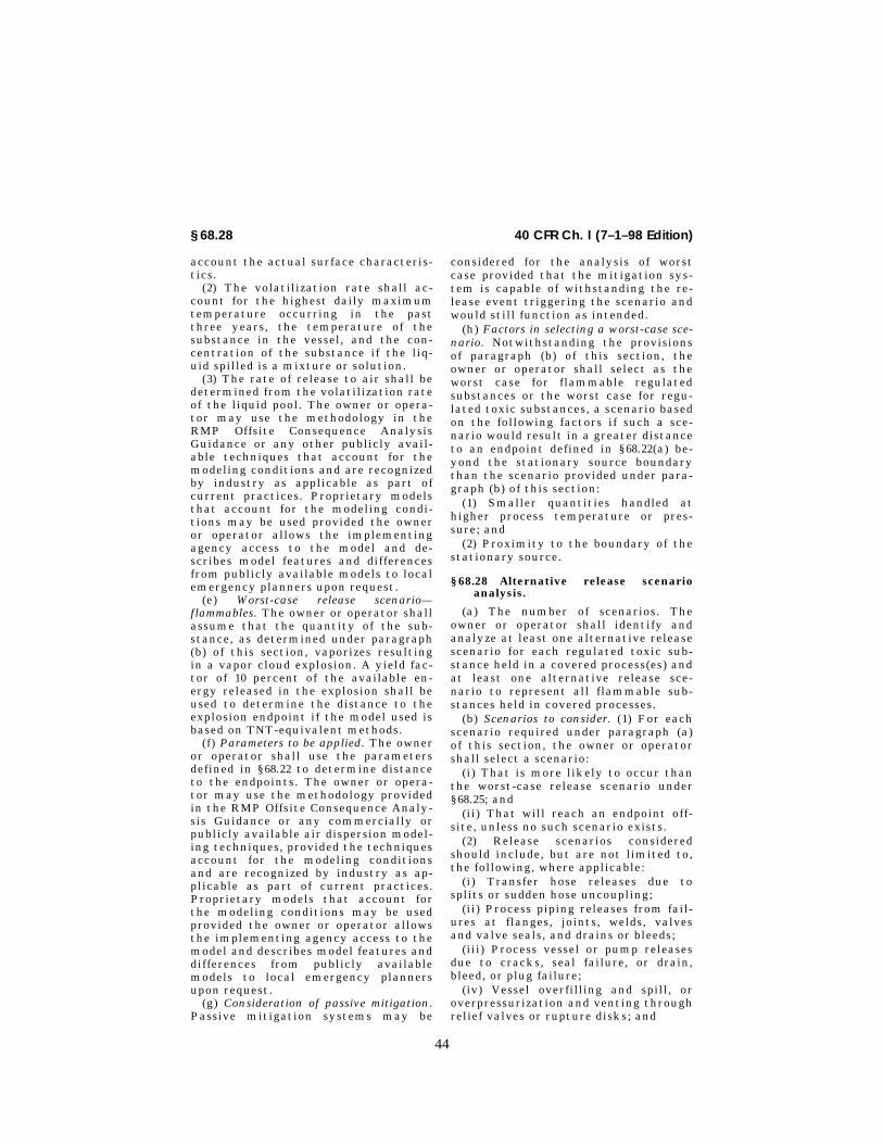
44
40 CFR Ch. I (7–1–98 Edition)§ 68.28
account the actual surface characteris-tics.
(2) The volatilization rate shall ac-count for the highest daily maximumtemperature occurring in the pastthree years, the temperature of thesubstance in the vessel, and the con-centration of the substance if the liq-uid spilled is a mixture or solution.
(3) The rate of release to air shall bedetermined from the volatilization rateof the liquid pool. The owner or opera-tor may use the methodology in theRMP Offsite Consequence AnalysisGuidance or any other publicly avail-able techniques that account for themodeling conditions and are recognizedby industry as applicable as part ofcurrent practices. Proprietary modelsthat account for the modeling condi-tions may be used provided the owneror operator allows the implementingagency access to the model and de-scribes model features and differencesfrom publicly available models to localemergency planners upon request.
(e) Worst-case release scenario—flammables. The owner or operator shallassume that the quantity of the sub-stance, as determined under paragraph(b) of this section, vaporizes resultingin a vapor cloud explosion. A yield fac-tor of 10 percent of the available en-ergy released in the explosion shall beused to determine the distance to theexplosion endpoint if the model used isbased on TNT-equivalent methods.
(f) Parameters to be applied. The owneror operator shall use the parametersdefined in § 68.22 to determine distanceto the endpoints. The owner or opera-tor may use the methodology providedin the RMP Offsite Consequence Analy-sis Guidance or any commercially orpublicly available air dispersion model-ing techniques, provided the techniquesaccount for the modeling conditionsand are recognized by industry as ap-plicable as part of current practices.Proprietary models that account forthe modeling conditions may be usedprovided the owner or operator allowsthe implementing agency access to themodel and describes model features anddifferences from publicly availablemodels to local emergency plannersupon request.
(g) Consideration of passive mitigation.Passive mitigation systems may be
considered for the analysis of worstcase provided that the mitigation sys-tem is capable of withstanding the re-lease event triggering the scenario andwould still function as intended.
(h) Factors in selecting a worst-case sce-nario. Notwithstanding the provisionsof paragraph (b) of this section, theowner or operator shall select as theworst case for flammable regulatedsubstances or the worst case for regu-lated toxic substances, a scenario basedon the following factors if such a sce-nario would result in a greater distanceto an endpoint defined in § 68.22(a) be-yond the stationary source boundarythan the scenario provided under para-graph (b) of this section:
(1) Smaller quantities handled athigher process temperature or pres-sure; and
(2) Proximity to the boundary of thestationary source.
§ 68.28 Alternative release scenarioanalysis.
(a) The number of scenarios. Theowner or operator shall identify andanalyze at least one alternative releasescenario for each regulated toxic sub-stance held in a covered process(es) andat least one alternative release sce-nario to represent all flammable sub-stances held in covered processes.
(b) Scenarios to consider. (1) For eachscenario required under paragraph (a)of this section, the owner or operatorshall select a scenario:
(i) That is more likely to occur thanthe worst-case release scenario under§ 68.25; and
(ii) That will reach an endpoint off-site, unless no such scenario exists.
(2) Release scenarios consideredshould include, but are not limited to,the following, where applicable:
(i) Transfer hose releases due tosplits or sudden hose uncoupling;
(ii) Process piping releases from fail-ures at flanges, joints, welds, valvesand valve seals, and drains or bleeds;
(iii) Process vessel or pump releasesdue to cracks, seal failure, or drain,bleed, or plug failure;
(iv) Vessel overfilling and spill, oroverpressurization and venting throughrelief valves or rupture disks; and
VerDate 25<JUN>98 07:40 Jul 22, 1998 Jkt 179149 PO 00000 Frm 00040 Fmt 8010 Sfmt 8010 Y:\SGML\179149T.XXX pfrm02 PsN: 179149T

45
Environmental Protection Agency § 68.39
(v) Shipping container mishandlingand breakage or puncturing leading toa spill.
(c) Parameters to be applied. Theowner or operator shall use the appro-priate parameters defined in § 68.22 todetermine distance to the endpoints.The owner or operator may use eitherthe methodology provided in the RMPOffsite Consequence Analysis Guidanceor any commercially or publicly avail-able air dispersion modeling tech-niques, provided the techniques ac-count for the specified modeling condi-tions and are recognized by industry asapplicable as part of current practices.Proprietary models that account forthe modeling conditions may be usedprovided the owner or operator allowsthe implementing agency access to themodel and describes model features anddifferences from publicly availablemodels to local emergency plannersupon request.
(d) Consideration of mitigation. Ac-tive and passive mitigation systemsmay be considered provided they arecapable of withstanding the event thattriggered the release and would still befunctional.
(e) Factors in selecting scenarios.The owner or operator shall considerthe following in selecting alternativerelease scenarios:
(1) The five-year accident historyprovided in § 68.42; and
(2) Failure scenarios identified under§ 68.50 or § 68.67.
§ 68.30 Defining offsite impacts—popu-lation.
(a) The owner or operator shall esti-mate in the RMP the population withina circle with its center at the point ofthe release and a radius determined bythe distance to the endpoint defined in§ 68.22(a).
(b) Population to be defined. Popu-lation shall include residential popu-lation. The presence of institutions(schools, hospitals, prisons), parks andrecreational areas, and major commer-cial, office, and industrial buildingsshall be noted in the RMP.
(c) Data sources acceptable. The owneror operator may use the most recentCensus data, or other updated informa-tion, to estimate the population poten-tially affected.
(d) Level of accuracy. Population shallbe estimated to two significant digits.
§ 68.33 Defining offsite impacts—envi-ronment.
(a) The owner or operator shall list inthe RMP environmental receptorswithin a circle with its center at thepoint of the release and a radius deter-mined by the distance to the endpointdefined in § 68.22(a) of this part.
(b) Data sources acceptable. Theowner or operator may rely on infor-mation provided on local U.S. Geologi-cal Survey maps or on any data sourcecontaining U.S.G.S. data to identifyenvironmental receptors.
68.36 Review and update.
(a) The owner or operator shall re-view and update the offsite con-sequence analyses at least once everyfive years.
(b) If changes in processes, quantitiesstored or handled, or any other aspectof the stationary source might reason-ably be expected to increase or de-crease the distance to the endpoint bya factor of two or more, the owner oroperator shall complete a revised anal-ysis within six months of the changeand submit a revised risk managementplan as provided in § 68.190.
§ 68.39 Documentation.
The owner or operator shall maintainthe following records on the offsiteconsequence analyses:
(a) For worst-case scenarios, a de-scription of the vessel or pipeline andsubstance selected as worst case, as-sumptions and parameters used, andthe rationale for selection; assump-tions shall include use of any adminis-trative controls and any passive miti-gation that were assumed to limit thequantity that could be released. Docu-mentation shall include the antici-pated effect of the controls and mitiga-tion on the release quantity and rate.
(b) For alternative release scenarios,a description of the scenarios identi-fied, assumptions and parameters used,and the rationale for the selection ofspecific scenarios; assumptions shallinclude use of any administrative con-trols and any mitigation that were as-sumed to limit the quantity that could
VerDate 25<JUN>98 07:40 Jul 22, 1998 Jkt 179149 PO 00000 Frm 00041 Fmt 8010 Sfmt 8010 Y:\SGML\179149T.XXX pfrm02 PsN: 179149T

46
40 CFR Ch. I (7–1–98 Edition)§ 68.42
be released. Documentation shall in-clude the effect of the controls andmitigation on the release quantity andrate.
(c) Documentation of estimatedquantity released, release rate, and du-ration of release.
(d) Methodology used to determinedistance to endpoints.
(e) Data used to estimate populationand environmental receptors poten-tially affected.
§ 68.42 Five-year accident history.
(a) The owner or operator shall in-clude in the five-year accident historyall accidental releases from coveredprocesses that resulted in deaths, inju-ries, or significant property damage onsite, or known offsite deaths, injuries,evacuations, sheltering in place, prop-erty damage, or environmental dam-age.
(b) Data required. For each accidentalrelease included, the owner or operatorshall report the following information:
(1) Date, time, and approximate dura-tion of the release;
(2) Chemical(s) released;(3) Estimated quantity released in
pounds;(4) The type of release event and its
source;(5) Weather conditions, if known;(6) On-site impacts;(7) Known offsite impacts;(8) Initiating event and contributing
factors if known;(9) Whether offsite responders were
notified if known; and(10) Operational or process changes
that resulted from investigation of therelease.
(c) Level of accuracy. Numerical esti-mates may be provided to two signifi-cant digits.
Subpart C—Program 2 PreventionProgram
SOURCE: 61 FR 31721, June 20, 1996, unlessotherwise noted.
§ 68.48 Safety information.(a) The owner or operator shall com-
pile and maintain the following up-to-date safety information related to the
regulated substances, processes, andequipment:
(1) Material Safety Data Sheets thatmeet the requirements of 29 CFR1910.1200(g);
(2) Maximum intended inventory ofequipment in which the regulated sub-stances are stored or processed;
(3) Safe upper and lower tempera-tures, pressures, flows, and composi-tions;
(4) Equipment specifications; and(5) Codes and standards used to de-
sign, build, and operate the process.(b) The owner or operator shall en-
sure that the process is designed incompliance with recognized and gen-erally accepted good engineering prac-tices. Compliance with Federal or stateregulations that address industry-spe-cific safe design or with industry-spe-cific design codes and standards may beused to demonstrate compliance withthis paragraph.
(c) The owner or operator shall up-date the safety information if a majorchange occurs that makes the informa-tion inaccurate.
§ 68.50 Hazard review.
(a) The owner or operator shall con-duct a review of the hazards associatedwith the regulated substances, process,and procedures. The review shall iden-tify the following:
(1) The hazards associated with theprocess and regulated substances;
(2) Opportunities for equipment mal-functions or human errors that couldcause an accidental release;
(3) The safeguards used or needed tocontrol the hazards or prevent equip-ment malfunction or human error; and
(4) Any steps used or needed to detector monitor releases.
(b) The owner or operator may usechecklists developed by persons or or-ganizations knowledgeable about theprocess and equipment as a guide toconducting the review. For processesdesigned to meet industry standards orFederal or state design rules, the haz-ard review shall, by inspecting allequipment, determine whether theprocess is designed, fabricated, and op-erated in accordance with the applica-ble standards or rules.
VerDate 25<JUN>98 07:40 Jul 22, 1998 Jkt 179149 PO 00000 Frm 00042 Fmt 8010 Sfmt 8010 Y:\SGML\179149T.XXX pfrm02 PsN: 179149T

47
Environmental Protection Agency § 68.56
(c) The owner or operator shall docu-ment the results of the review and en-sure that problems identified are re-solved in a timely manner.
(d) The review shall be updated atleast once every five years. The owneror operator shall also conduct reviewswhenever a major change in the proc-ess occurs; all issues identified in thereview shall be resolved before startupof the changed process.
§ 68.52 Operating procedures.(a) The owner or operator shall pre-
pare written operating procedures thatprovide clear instructions or steps forsafely conducting activities associatedwith each covered process consistentwith the safety information for thatprocess. Operating procedures or in-structions provided by equipment man-ufacturers or developed by persons ororganizations knowledgeable about theprocess and equipment may be used asa basis for a stationary source’s operat-ing procedures.
(b) The procedures shall address thefollowing:
(1) Initial startup;(2) Normal operations;(3) Temporary operations;(4) Emergency shutdown and oper-
ations;(5) Normal shutdown;(6) Startup following a normal or
emergency shutdown or a major changethat requires a hazard review;
(7) Consequences of deviations andsteps required to correct or avoid devi-ations; and
(8) Equipment inspections.(c) The owner or operator shall en-
sure that the operating procedures areupdated, if necessary, whenever amajor change occurs and prior to start-up of the changed process.
§ 68.54 Training.(a) The owner or operator shall en-
sure that each employee presently op-erating a process, and each employeenewly assigned to a covered processhave been trained or tested competentin the operating procedures provided in§ 68.52 that pertain to their duties. Forthose employees already operating aprocess on June 21, 1999, the owner oroperator may certify in writing thatthe employee has the required knowl-
edge, skills, and abilities to safelycarry out the duties and responsibil-ities as provided in the operating pro-cedures.
(b) Refresher training. Refreshertraining shall be provided at leastevery three years, and more often ifnecessary, to each employee operatinga process to ensure that the employeeunderstands and adheres to the currentoperating procedures of the process.The owner or operator, in consultationwith the employees operating the proc-ess, shall determine the appropriatefrequency of refresher training.
(c) The owner or operator may usetraining conducted under Federal orstate regulations or under industry-specific standards or codes or trainingconducted by covered process equip-ment vendors to demonstrate compli-ance with this section to the extentthat the training meets the require-ments of this section.
(d) The owner or operator shall en-sure that operators are trained in anyupdated or new procedures prior tostartup of a process after a majorchange.
§ 68.56 Maintenance.
(a) The owner or operator shall pre-pare and implement procedures tomaintain the on-going mechanical in-tegrity of the process equipment. Theowner or operator may use proceduresor instructions provided by coveredprocess equipment vendors or proce-dures in Federal or state regulations orindustry codes as the basis for station-ary source maintenance procedures.
(b) The owner or operator shall trainor cause to be trained each employeeinvolved in maintaining the on-goingmechanical integrity of the process. Toensure that the employee can performthe job tasks in a safe manner, eachsuch employee shall be trained in thehazards of the process, in how to avoidor correct unsafe conditions, and in theprocedures applicable to the employ-ee’s job tasks.
(c) Any maintenance contractor shallensure that each contract maintenanceemployee is trained to perform themaintenance procedures developedunder paragraph (a) of this section.
VerDate 25<JUN>98 07:40 Jul 22, 1998 Jkt 179149 PO 00000 Frm 00043 Fmt 8010 Sfmt 8010 Y:\SGML\179149T.XXX pfrm02 PsN: 179149T

48
40 CFR Ch. I (7–1–98 Edition)§ 68.58
(d) The owner or operator shall per-form or cause to be performed inspec-tions and tests on process equipment.Inspection and testing procedures shallfollow recognized and generally accept-ed good engineering practices. The fre-quency of inspections and tests of proc-ess equipment shall be consistent withapplicable manufacturers’ rec-ommendations, industry standards orcodes, good engineering practices, andprior operating experience.
§ 68.58 Compliance audits.(a) The owner or operator shall cer-
tify that they have evaluated compli-ance with the provisions of this sub-part at least every three years to ver-ify that the procedures and practicesdeveloped under the rule are adequateand are being followed.
(b) The compliance audit shall beconducted by at least one personknowledgeable in the process.
(c) The owner or operator shall de-velop a report of the audit findings.
(d) The owner or operator shallpromptly determine and document anappropriate response to each of thefindings of the compliance audit anddocument that deficiencies have beencorrected.
(e) The owner or operator shall retainthe two (2) most recent complianceaudit reports. This requirement doesnot apply to any compliance audit re-port that is more than five years old.
§ 68.60 Incident investigation.(a) The owner or operator shall inves-
tigate each incident which resulted in,or could reasonably have resulted in acatastrophic release.
(b) An incident investigation shall beinitiated as promptly as possible, butnot later than 48 hours following theincident.
(c) A summary shall be prepared atthe conclusion of the investigationwhich includes at a minimum:
(1) Date of incident;(2) Date investigation began;(3) A description of the incident;(4) The factors that contributed to
the incident; and,(5) Any recommendations resulting
from the investigation.(d) The owner or operator shall
promptly address and resolve the inves-
tigation findings and recommenda-tions. Resolutions and corrective ac-tions shall be documented.
(e) The findings shall be reviewedwith all affected personnel whose jobtasks are affected by the findings.
(f) Investigation summaries shall beretained for five years.
Subpart D—Program 3 PreventionProgram
SOURCE: 61 FR 31722, June 20, 1996, unlessotherwise noted.
§ 68.65 Process safety information.
(a) In accordance with the scheduleset forth in § 68.67, the owner or opera-tor shall complete a compilation ofwritten process safety information be-fore conducting any process hazardanalysis required by the rule. The com-pilation of written process safety infor-mation is to enable the owner or opera-tor and the employees involved in oper-ating the process to identify and under-stand the hazards posed by those proc-esses involving regulated substances.This process safety information shallinclude information pertaining to thehazards of the regulated substancesused or produced by the process, infor-mation pertaining to the technology ofthe process, and information pertain-ing to the equipment in the process.
(b) Information pertaining to thehazards of the regulated substances inthe process. This information shallconsist of at least the following:
(1) Toxicity information;(2) Permissible exposure limits;(3) Physical data;(4) Reactivity data:(5) Corrosivity data;(6) Thermal and chemical stability
data; and(7) Hazardous effects of inadvertent
mixing of different materials thatcould foreseeably occur.
NOTE TO PARAGRAPH (b): Material SafetyData Sheets meeting the requirements of 29CFR 1910.1200(g) may be used to comply withthis requirement to the extent they containthe information required by this subpara-graph.
(c) Information pertaining to thetechnology of the process.
VerDate 25<JUN>98 10:48 Jul 29, 1998 Jkt 179149 PO 00000 Frm 00044 Fmt 8010 Sfmt 8010 Y:\SGML\179149T.XXX pfrm02 PsN: 179149T

49
Environmental Protection Agency § 68.67
(1) Information concerning the tech-nology of the process shall include atleast the following:
(i) A block flow diagram or simplifiedprocess flow diagram;
(ii) Process chemistry;(iii) Maximum intended inventory;(iv) Safe upper and lower limits for
such items as temperatures, pressures,flows or compositions; and,
(v) An evaluation of the consequencesof deviations.
(2) Where the original technical in-formation no longer exists, such infor-mation may be developed in conjunc-tion with the process hazard analysisin sufficient detail to support the anal-ysis.
(d) Information pertaining to theequipment in the process.
(1) Information pertaining to theequipment in the process shall include:
(i) Materials of construction;(ii) Piping and instrument diagrams
(P&ID’s);(iii) Electrical classification;(iv) Relief system design and design
basis;(v) Ventilation system design;(vi) Design codes and standards em-
ployed;(vii) Material and energy balances for
processes built after June 21, 1999; and(viii) Safety systems (e.g. interlocks,
detection or suppression systems).(2) The owner or operator shall docu-
ment that equipment complies withrecognized and generally accepted goodengineering practices.
(3) For existing equipment designedand constructed in accordance withcodes, standards, or practices that areno longer in general use, the owner oroperator shall determine and documentthat the equipment is designed, main-tained, inspected, tested, and operatingin a safe manner.
§ 68.67 Process hazard analysis.(a) The owner or operator shall per-
form an initial process hazard analysis(hazard evaluation) on processes cov-ered by this part. The process hazardanalysis shall be appropriate to thecomplexity of the process and shallidentify, evaluate, and control the haz-ards involved in the process. The owneror operator shall determine and docu-ment the priority order for conducting
process hazard analyses based on a ra-tionale which includes such consider-ations as extent of the process hazards,number of potentially affected employ-ees, age of the process, and operatinghistory of the process. The process haz-ard analysis shall be conducted as soonas possible, but not later than June 21,1999. Process hazards analyses com-pleted to comply with 29 CFR1910.119(e) are acceptable as initialprocess hazards analyses. These processhazard analyses shall be updated andrevalidated, based on their completiondate.
(b) The owner or operator shall useone or more of the following meth-odologies that are appropriate to deter-mine and evaluate the hazards of theprocess being analyzed.
(1) What-If;(2) Checklist;(3) What-If/Checklist;(4) Hazard and Operability Study
(HAZOP);(5) Failure Mode and Effects Analysis
(FMEA);(6) Fault Tree Analysis; or(7) An appropriate equivalent meth-
odology.(c) The process hazard analysis shall
address:(1) The hazards of the process;(2) The identification of any previous
incident which had a likely potentialfor catastrophic consequences.
(3) Engineering and administrativecontrols applicable to the hazards andtheir interrelationships such as appro-priate application of detection meth-odologies to provide early warning ofreleases. (Acceptable detection meth-ods might include process monitoringand control instrumentation withalarms, and detection hardware such ashydrocarbon sensors.);
(4) Consequences of failure of engi-neering and administrative controls;
(5) Stationary source siting;(6) Human factors; and(7) A qualitative evaluation of a
range of the possible safety and healtheffects of failure of controls.
(d) The process hazard analysis shallbe performed by a team with expertisein engineering and process operations,and the team shall include at least oneemployee who has experience andknowledge specific to the process being
VerDate 25<JUN>98 07:40 Jul 22, 1998 Jkt 179149 PO 00000 Frm 00045 Fmt 8010 Sfmt 8010 Y:\SGML\179149T.XXX pfrm02 PsN: 179149T

50
40 CFR Ch. I (7–1–98 Edition)§ 68.69
evaluated. Also, one member of theteam must be knowledgeable in thespecific process hazard analysis meth-odology being used.
(e) The owner or operator shall estab-lish a system to promptly address theteam’s findings and recommendations;assure that the recommendations areresolved in a timely manner and thatthe resolution is documented; docu-ment what actions are to be taken;complete actions as soon as possible;develop a written schedule of whenthese actions are to be completed; com-municate the actions to operating,maintenance and other employeeswhose work assignments are in theprocess and who may be affected by therecommendations or actions.
(f) At least every five (5) years afterthe completion of the initial processhazard analysis, the process hazardanalysis shall be updated and revali-dated by a team meeting the require-ments in paragraph (d) of this section,to assure that the process hazard anal-ysis is consistent with the currentprocess. Updated and revalidated proc-ess hazard analyses completed to com-ply with 29 CFR 1910.119(e) are accept-able to meet the requirements of thisparagraph.
(g) The owner or operator shall re-tain process hazards analyses and up-dates or revalidations for each processcovered by this section, as well as thedocumented resolution of recommenda-tions described in paragraph (e) of thissection for the life of the process.
§ 68.69 Operating procedures.
(a) The owner or operator shall de-velop and implement written operatingprocedures that provide clear instruc-tions for safely conducting activitiesinvolved in each covered process con-sistent with the process safety infor-mation and shall address at least thefollowing elements.
(1) Steps for each operating phase:(i) Initial startup;(ii) Normal operations;(iii) Temporary operations;(iv) Emergency shutdown including
the conditions under which emergencyshutdown is required, and the assign-ment of shutdown responsibility toqualified operators to ensure that
emergency shutdown is executed in asafe and timely manner.
(v) Emergency operations;(vi) Normal shutdown; and,(vii) Startup following a turnaround,
or after an emergency shutdown.(2) Operating limits:(i) Consequences of deviation; and(ii) Steps required to correct or avoid
deviation.(3) Safety and health considerations:(i) Properties of, and hazards pre-
sented by, the chemicals used in theprocess;
(ii) Precautions necessary to preventexposure, including engineering con-trols, administrative controls, and per-sonal protective equipment;
(iii) Control measures to be taken ifphysical contact or airborne exposureoccurs;
(iv) Quality control for raw materialsand control of hazardous chemical in-ventory levels; and,
(v) Any special or unique hazards.(4) Safety systems and their func-
tions.(b) Operating procedures shall be
readily accessible to employees whowork in or maintain a process.
(c) The operating procedures shall bereviewed as often as necessary to as-sure that they reflect current operat-ing practice, including changes that re-sult from changes in process chemicals,technology, and equipment, andchanges to stationary sources. Theowner or operator shall certify annu-ally that these operating proceduresare current and accurate.
(d) The owner or operator shall de-velop and implement safe work prac-tices to provide for the control of haz-ards during operations such as lockout/tagout; confined space entry; openingprocess equipment or piping; and con-trol over entrance into a stationarysource by maintenance, contractor,laboratory, or other support personnel.These safe work practices shall applyto employees and contractor employ-ees.
§ 68.71 Training.(a) Initial training. (1) Each employee
presently involved in operating a proc-ess, and each employee before being in-volved in operating a newly assignedprocess, shall be trained in an overview
VerDate 25<JUN>98 07:40 Jul 22, 1998 Jkt 179149 PO 00000 Frm 00046 Fmt 8010 Sfmt 8010 Y:\SGML\179149T.XXX pfrm02 PsN: 179149T

51
Environmental Protection Agency § 68.73
of the process and in the operating pro-cedures as specified in § 68.69. Thetraining shall include emphasis on thespecific safety and health hazards,emergency operations including shut-down, and safe work practices applica-ble to the employee’s job tasks.
(2) In lieu of initial training for thoseemployees already involved in operat-ing a process on June 21, 1999 an owneror operator may certify in writing thatthe employee has the required knowl-edge, skills, and abilities to safelycarry out the duties and responsibil-ities as specified in the operating pro-cedures.
(b) Refresher training. Refresher train-ing shall be provided at least everythree years, and more often if nec-essary, to each employee involved inoperating a process to assure that theemployee understands and adheres tothe current operating procedures of theprocess. The owner or operator, in con-sultation with the employees involvedin operating the process, shall deter-mine the appropriate frequency of re-fresher training.
(c) Training documentation. The owneror operator shall ascertain that eachemployee involved in operating a proc-ess has received and understood thetraining required by this paragraph.The owner or operator shall prepare arecord which contains the identity ofthe employee, the date of training, andthe means used to verify that the em-ployee understood the training.
§ 68.73 Mechanical integrity.
(a) Application. Paragraphs (b)through (f) of this section apply to thefollowing process equipment:
(1) Pressure vessels and storagetanks;
(2) Piping systems (including pipingcomponents such as valves);
(3) Relief and vent systems and de-vices;
(4) Emergency shutdown systems;(5) Controls (including monitoring
devices and sensors, alarms, and inter-locks) and,
(6) Pumps.(b) Written procedures. The owner or
operator shall establish and implementwritten procedures to maintain the on-going integrity of process equipment.
(c) Training for process maintenanceactivities. The owner or operator shalltrain each employee involved in main-taining the on-going integrity of proc-ess equipment in an overview of thatprocess and its hazards and in the pro-cedures applicable to the employee’sjob tasks to assure that the employeecan perform the job tasks in a safemanner.
(d) Inspection and testing. (1) Inspec-tions and tests shall be performed onprocess equipment.
(2) Inspection and testing proceduresshall follow recognized and generallyaccepted good engineering practices.
(3) The frequency of inspections andtests of process equipment shall be con-sistent with applicable manufacturers’recommendations and good engineeringpractices, and more frequently if deter-mined to be necessary by prior operat-ing experience.
(4) The owner or operator shall docu-ment each inspection and test that hasbeen performed on process equipment.The documentation shall identify thedate of the inspection or test, the nameof the person who performed the in-spection or test, the serial number orother identifier of the equipment onwhich the inspection or test was per-formed, a description of the inspectionor test performed, and the results ofthe inspection or test.
(e) Equipment deficiencies. The owneror operator shall correct deficiencies inequipment that are outside acceptablelimits (defined by the process safety in-formation in § 68.65) before further useor in a safe and timely manner whennecessary means are taken to assuresafe operation.
(f) Quality assurance. (1) In the con-struction of new plants and equipment,the owner or operator shall assure thatequipment as it is fabricated is suit-able for the process application forwhich they will be used.
(2) Appropriate checks and inspec-tions shall be performed to assure thatequipment is installed properly andconsistent with design specificationsand the manufacturer’s instructions.
(3) The owner or operator shall as-sure that maintenance materials, spareparts and equipment are suitable forthe process application for which theywill be used.
VerDate 25<JUN>98 07:40 Jul 22, 1998 Jkt 179149 PO 00000 Frm 00047 Fmt 8010 Sfmt 8010 Y:\SGML\179149T.XXX pfrm02 PsN: 179149T

52
40 CFR Ch. I (7–1–98 Edition)§ 68.75
§ 68.75 Management of change.(a) The owner or operator shall estab-
lish and implement written proceduresto manage changes (except for ‘‘re-placements in kind’’) to process chemi-cals, technology, equipment, and proce-dures; and, changes to stationarysources that affect a covered process.
(b) The procedures shall assure thatthe following considerations are ad-dressed prior to any change:
(1) The technical basis for the pro-posed change;
(2) Impact of change on safety andhealth;
(3) Modifications to operating proce-dures;
(4) Necessary time period for thechange; and,
(5) Authorization requirements forthe proposed change.
(c) Employees involved in operating aprocess and maintenance and contractemployees whose job tasks will be af-fected by a change in the process shallbe informed of, and trained in, thechange prior to start-up of the processor affected part of the process.
(d) If a change covered by this para-graph results in a change in the processsafety information required by § 68.65 ofthis part, such information shall be up-dated accordingly.
(e) If a change covered by this para-graph results in a change in the operat-ing procedures or practices required by§ 68.69, such procedures or practicesshall be updated accordingly.
§ 68.77 Pre-startup review.(a) The owner or operator shall per-
form a pre-startup safety review fornew stationary sources and for modi-fied stationary sources when the modi-fication is significant enough to re-quire a change in the process safety in-formation.
(b) The pre-startup safety reviewshall confirm that prior to the intro-duction of regulated substances to aprocess:
(1) Construction and equipment is inaccordance with design specifications;
(2) Safety, operating, maintenance,and emergency procedures are in placeand are adequate;
(3) For new stationary sources, aprocess hazard analysis has been per-formed and recommendations have
been resolved or implemented beforestartup; and modified stationarysources meet the requirements con-tained in management of change,§ 68.75.
(4) Training of each employee in-volved in operating a process has beencompleted.
§ 68.79 Compliance audits.(a) The owner or operator shall cer-
tify that they have evaluated compli-ance with the provisions of this sectionat least every three years to verifythat the procedures and practices de-veloped under the standard are ade-quate and are being followed.
(b) The compliance audit shall beconducted by at least one personknowledgeable in the process.
(c) A report of the findings of theaudit shall be developed.
(d) The owner or operator shallpromptly determine and document anappropriate response to each of thefindings of the compliance audit, anddocument that deficiencies have beencorrected.
(e) The owner or operator shall retainthe two (2) most recent complianceaudit reports.
§ 68.81 Incident investigation.(a) The owner or operator shall inves-
tigate each incident which resulted in,or could reasonably have resulted in acatastrophic release of a regulated sub-stance.
(b) An incident investigation shall beinitiated as promptly as possible, butnot later than 48 hours following theincident.
(c) An incident investigation teamshall be established and consist of atleast one person knowledgeable in theprocess involved, including a contractemployee if the incident involved workof the contractor, and other personswith appropriate knowledge and experi-ence to thoroughly investigate andanalyze the incident.
(d) A report shall be prepared at theconclusion of the investigation whichincludes at a minimum:
(1) Date of incident;(2) Date investigation began;(3) A description of the incident;(4) The factors that contributed to
the incident; and,
VerDate 25<JUN>98 10:35 Jul 29, 1998 Jkt 179149 PO 00000 Frm 00048 Fmt 8010 Sfmt 8010 Y:\SGML\179149T.XXX pfrm02 PsN: 179149T

53
Environmental Protection Agency § 68.87
(5) Any recommendations resultingfrom the investigation.
(e) The owner or operator shall estab-lish a system to promptly address andresolve the incident report findings andrecommendations. Resolutions and cor-rective actions shall be documented.
(f) The report shall be reviewed withall affected personnel whose job tasksare relevant to the incident findings in-cluding contract employees where ap-plicable.
(g) Incident investigation reportsshall be retained for five years.
§ 68.83 Employee participation.(a) The owner or operator shall de-
velop a written plan of action regard-ing the implementation of the em-ployee participation required by thissection.
(b) The owner or operator shall con-sult with employees and their rep-resentatives on the conduct and devel-opment of process hazards analyses andon the development of the other ele-ments of process safety management inthis rule.
(c) The owner or operator shall pro-vide to employees and their representa-tives access to process hazard analysesand to all other information requiredto be developed under this rule.
§ 68.85 Hot work permit.(a) The owner or operator shall issue
a hot work permit for hot work oper-ations conducted on or near a coveredprocess.
(b) The permit shall document thatthe fire prevention and protection re-quirements in 29 CFR 1910.252(a) havebeen implemented prior to beginningthe hot work operations; it shall indi-cate the date(s) authorized for hotwork; and identify the object on whichhot work is to be performed. The per-mit shall be kept on file until comple-tion of the hot work operations.
§ 68.87 Contractors.(a) Application. This section applies
to contractors performing maintenanceor repair, turnaround, major renova-tion, or specialty work on or adjacentto a covered process. It does not applyto contractors providing incidentalservices which do not influence processsafety, such as janitorial work, food
and drink services, laundry, delivery orother supply services.
(b) Owner or operator responsibilities.(1) The owner or operator, when select-ing a contractor, shall obtain andevaluate information regarding thecontract owner or operator’s safetyperformance and programs.
(2) The owner or operator shall in-form contract owner or operator of theknown potential fire, explosion, ortoxic release hazards related to thecontractor’s work and the process.
(3) The owner or operator shall ex-plain to the contract owner or operatorthe applicable provisions of subpart Eof this part.
(4) The owner or operator shall de-velop and implement safe work prac-tices consistent with § 68.69(d), to con-trol the entrance, presence, and exit ofthe contract owner or operator andcontract employees in covered processareas.
(5) The owner or operator shall peri-odically evaluate the performance ofthe contract owner or operator in ful-filling their obligations as specified inparagraph (c) of this section.
(c) Contract owner or operator respon-sibilities. (1) The contract owner or op-erator shall assure that each contractemployee is trained in the work prac-tices necessary to safely perform his/her job.
(2) The contract owner or operatorshall assure that each contract em-ployee is instructed in the known po-tential fire, explosion, or toxic releasehazards related to his/her job and theprocess, and the applicable provisionsof the emergency action plan.
(3) The contract owner or operatorshall document that each contract em-ployee has received and understood thetraining required by this section. Thecontract owner or operator shall pre-pare a record which contains the iden-tity of the contract employee, the dateof training, and the means used to ver-ify that the employee understood thetraining.
(4) The contract owner or operatorshall assure that each contract em-ployee follows the safety rules of thestationary source including the safework practices required by § 68.69(d).
(5) The contract owner or operatorshall advise the owner or operator of
VerDate 25<JUN>98 07:40 Jul 22, 1998 Jkt 179149 PO 00000 Frm 00049 Fmt 8010 Sfmt 8010 Y:\SGML\179149T.XXX pfrm02 PsN: 179149T

54
40 CFR Ch. I (7–1–98 Edition)§ 68.90
any unique hazards presented by thecontract owner or operator’s work, orof any hazards found by the contractowner or operator’s work.
Subpart E—Emergency Response
SOURCE: 61 FR 31725, June 20, 1996, unlessotherwise noted.
§ 68.90 Applicability.
(a) Except as provided in paragraph(b) of this section, the owner or opera-tor of a stationary source with Pro-gram 2 and Program 3 processes shallcomply with the requirements of § 68.95.
(b) The owner or operator of station-ary source whose employees will notrespond to accidental releases of regu-lated substances need not comply with§ 68.95 of this part provided that theymeet the following:
(1) For stationary sources with anyregulated toxic substance held in aprocess above the threshold quantity,the stationary source is included in thecommunity emergency response plandeveloped under 42 U.S.C. 11003;
(2) For stationary sources with onlyregulated flammable substances held ina process above the threshold quantity,the owner or operator has coordinatedresponse actions with the local fire de-partment; and
(3) Appropriate mechanisms are inplace to notify emergency responderswhen there is a need for a response.
§ 68.95 Emergency response program.
(a) The owner or operator shall de-velop and implement an emergency re-sponse program for the purpose of pro-tecting public health and the environ-ment. Such program shall include thefollowing elements:
(1) An emergency response plan,which shall be maintained at the sta-tionary source and contain at least thefollowing elements:
(i) Procedures for informing the pub-lic and local emergency response agen-cies about accidental releases;
(ii) Documentation of proper first-aidand emergency medical treatment nec-essary to treat accidental human expo-sures; and
(iii) Procedures and measures foremergency response after an accidentalrelease of a regulated substance;
(2) Procedures for the use of emer-gency response equipment and for itsinspection, testing, and maintenance;
(3) Training for all employees in rel-evant procedures; and
(4) Procedures to review and update,as appropriate, the emergency responseplan to reflect changes at the station-ary source and ensure that employeesare informed of changes.
(b) A written plan that complies withother Federal contingency plan regula-tions or is consistent with the ap-proach in the National ResponseTeam’s Integrated Contingency PlanGuidance (‘‘One Plan’’) and that,among other matters, includes the ele-ments provided in paragraph (a) of thissection, shall satisfy the requirementsof this section if the owner or operatoralso complies with paragraph (c) of thissection.
(c) The emergency response plan de-veloped under paragraph (a)(1) of thissection shall be coordinated with thecommunity emergency response plandeveloped under 42 U.S.C. 11003. Uponrequest of the local emergency plan-ning committee or emergency responseofficials, the owner or operator shallpromptly provide to the local emer-gency response officials informationnecessary for developing and imple-menting the community emergency re-sponse plan.
Subpart F—Regulated Substancesfor Accidental Release Prevention
SOURCE: 59 FR 4493, Jan. 31, 1994, unlessotherwise noted. Redesignated at 61 FR 31717,June 20, 1996.
§ 68.100 Purpose.This subpart designates substances
to be listed under section 112(r)(3), (4),and (5) of the Clean Air Act, as amend-ed, identifies their threshold quan-tities, and establishes the requirementsfor petitioning to add or delete sub-stances from the list.
§ 68.115 Threshold determination.(a) A threshold quantity of a regu-
lated substance listed in § 68.130 is
VerDate 25<JUN>98 07:40 Jul 22, 1998 Jkt 179149 PO 00000 Frm 00050 Fmt 8010 Sfmt 8010 Y:\SGML\179149T.XXX pfrm02 PsN: 179149T

55
Environmental Protection Agency § 68.115
present at a stationary source if thetotal quantity of the regulated sub-stance contained in a process exceedsthe threshold.
(b) For the purposes of determiningwhether more than a threshold quan-tity of a regulated substance is presentat the stationary source, the followingexemptions apply:
(1) Concentrations of a regulated toxicsubstance in a mixture. If a regulatedsubstance is present in a mixture andthe concentration of the substance isbelow one percent by weight of themixture, the amount of the substancein the mixture need not be consideredwhen determining whether more than athreshold quantity is present at thestationary source. Except for oleum,toluene 2,4-diisocyanate, toluene 2,6-diisocyanate, and toluene diisocyanate(unspecified isomer), if the concentra-tion of the regulated substance in themixture is one percent or greater byweight, but the owner or operator candemonstrate that the partial pressureof the regulated substance in the mix-ture (solution) under handling or stor-age conditions in any portion of theprocess is less than 10 millimeters ofmercury (mm Hg), the amount of thesubstance in the mixture in that por-tion of the process need not be consid-ered when determining whether morethan a threshold quantity is present atthe stationary source. The owner or op-erator shall document this partial pres-sure measurement or estimate.
(2) Concentrations of a regulated flam-mable substance in a mixture. (i) Generalprovision. If a regulated substance ispresent in a mixture and the con-centration of the substance is belowone percent by weight of the mixture,the mixture need not be consideredwhen determining whether more than athreshold quantity of the regulatedsubstance is present at the stationarysource. Except as provided in para-graph (b)(2) (ii) and (iii) of this section,if the concentration of the substance isone percent or greater by weight of themixture, then, for purposes of deter-mining whether a threshold quantity ispresent at the stationary source, theentire weight of the mixture shall betreated as the regulated substance un-less the owner or operator can dem-onstrate that the mixture itself does
not have a National Fire ProtectionAssociation flammability hazard rat-ing of 4. The demonstration shall be inaccordance with the definition of flam-mability hazard rating 4 in the NFPA704, Standard System for the Identi-fication of the Hazards of Materials forEmergency Response, National FireProtection Association, Quincy, MA,1996. Available from the National FireProtection Association, 1Batterymarch Park, Quincy, MA 02269–9101. This incorporation by referencewas approved by the Director of theFederal Register in accordance with 5U.S.C. 552(a) and 1 CFR part 51. Copiesmay be inspected at the EnvironmentalProtection Agency Air Docket (6102),Attn: Docket No. A–96–O8, WatersideMall, 401 M. St. SW., Washington DC;or at the Office of Federal Register at800 North Capitol St., NW, Suite 700,Washington, DC. Boiling point andflash point shall be defined and deter-mined in accordance with NFPA 30,Flammable and Combustible LiquidsCode, National Fire Protection Asso-ciation, Quincy, MA, 1996. Availablefrom the National Fire Protection As-sociation, 1 Batterymarch Park, Quin-cy, MA 02269–9101. This incorporationby reference was approved by the Di-rector of the Federal Register in ac-cordance with 5 U.S.C. 552(a) and 1 CFRpart 51. Copies may be inspected at theEnvironmental Protection Agency AirDocket (6102), Attn: Docket No. A–96–O8, Waterside Mall, 401 M. St. SW.,Washington DC; or at the Office of Fed-eral Register at 800 North Capitol St.,NW., Suite 700, Washington, DC. Theowner or operator shall document theNational Fire Protection Associationflammability hazard rating.
(ii) Gasoline. Regulated substances ingasoline, when in distribution or relat-ed storage for use as fuel for internalcombustion engines, need not be con-sidered when determining whethermore than a threshold quantity ispresent at a stationary source.
(iii) Naturally occurring hydrocarbonmixtures. Prior to entry into a naturalgas processing plant or a petroleum re-fining process unit, regulated sub-stances in naturally occurring hydro-carbon mixtures need not be consideredwhen determining whether more than a
VerDate 25<JUN>98 07:40 Jul 22, 1998 Jkt 179149 PO 00000 Frm 00051 Fmt 8010 Sfmt 8010 Y:\SGML\179149T.XXX pfrm02 PsN: 179149T

56
40 CFR Ch. I (7–1–98 Edition)§ 68.120
threshold quantity is present at a sta-tionary source. Naturally occurringhydrocarbon mixtures include anycombination of the following: conden-sate, crude oil, field gas, and producedwater, each as defined in § 68.3 of thispart.
(3) Articles. Regulated substances con-tained in articles need not be consid-ered when determining whether morethan a threshold quantity is present atthe stationary source.
(4) Uses. Regulated substances, whenin use for the following purposes, neednot be included in determining whethermore than a threshold quantity ispresent at the stationary source:
(i) Use as a structural component ofthe stationary source;
(ii) Use of products for routine jani-torial maintenance;
(iii) Use by employees of foods, drugs,cosmetics, or other personal items con-taining the regulated substance; and
(iv) Use of regulated substancespresent in process water or non-contactcooling water as drawn from the envi-ronment or municipal sources, or useof regulated substances present in airused either as compressed air or as partof combustion.
(5) Activities in laboratories. If a regu-lated substance is manufactured, proc-essed, or used in a laboratory at a sta-tionary source under the supervision ofa technically qualified individual as de-fined in § 720.3(ee) of this chapter, thequantity of the substance need not beconsidered in determining whether athreshold quantity is present. This ex-emption does not apply to:
(i) Specialty chemical production;(ii) Manufacture, processing, or use
of substances in pilot plant scale oper-ations; and
(iii) Activities conducted outside thelaboratory.
[59 FR 4493, Jan. 31, 1994. Redesignated at 61FR 31717, June 20, 1996, as amended at 63 FR645, Jan. 6, 1998]
§ 68.120 Petition process.(a) Any person may petition the Ad-
ministrator to modify, by addition ordeletion, the list of regulated sub-stances identified in § 68.130. Based onthe information presented by the peti-tioner, the Administrator may grant ordeny a petition.
(b) A substance may be added to thelist if, in the case of an accidental re-lease, it is known to cause or may bereasonably anticipated to cause death,injury, or serious adverse effects tohuman health or the environment.
(c) A substance may be deleted fromthe list if adequate data on the healthand environmental effects of the sub-stance are available to determine thatthe substance, in the case of an acci-dental release, is not known to causeand may not be reasonably anticipatedto cause death, injury, or serious ad-verse effects to human health or theenvironment.
(d) No substance for which a nationalprimary ambient air quality standardhas been established shall be added tothe list. No substance regulated undertitle VI of the Clean Air Act, as amend-ed, shall be added to the list.
(e) The burden of proof is on the peti-tioner to demonstrate that the criteriafor addition and deletion are met. A pe-tition will be denied if this demonstra-tion is not made.
(f) The Administrator will not acceptadditional petitions on the same sub-stance following publication of a finalnotice of the decision to grant or denya petition, unless new data becomesavailable that could significantly af-fect the basis for the decision.
(g) Petitions to modify the list ofregulated substances must contain thefollowing:
(1) Name and address of the peti-tioner and a brief description of the or-ganization(s) that the petitioner rep-resents, if applicable;
(2) Name, address, and telephonenumber of a contact person for the pe-tition;
(3) Common chemical name(s), com-mon synonym(s), Chemical AbstractsService number, and chemical formulaand structure;
(4) Action requested (add or delete asubstance);
(5) Rationale supporting the petition-er’s position; that is, how the sub-stance meets the criteria for additionand deletion. A short summary of therationale must be submitted alongwith a more detailed narrative; and
VerDate 25<JUN>98 07:40 Jul 22, 1998 Jkt 179149 PO 00000 Frm 00052 Fmt 8010 Sfmt 8010 Y:\SGML\179149T.XXX pfrm02 PsN: 179149T

57
Environmental Protection Agency § 68.130
(6) Supporting data; that is, the peti-tion must include sufficient informa-tion to scientifically support the re-quest to modify the list. Such informa-tion shall include:
(i) A list of all support documents;(ii) Documentation of literature
searches conducted, including, but notlimited to, identification of the data-base(s) searched, the search strategy,dates covered, and printed results;
(iii) Effects data (animal, human, andenvironmental test data) indicatingthe potential for death, injury, or seri-ous adverse human and environmentalimpacts from acute exposure followingan accidental release; printed copies ofthe data sources, in English, should beprovided; and
(iv) Exposure data or previous acci-dent history data, indicating the po-tential for serious adverse humanhealth or environmental effects froman accidental release. These data mayinclude, but are not limited to, phys-ical and chemical properties of the sub-stance, such as vapor pressure; model-ing results, including data and assump-tions used and model documentation;and historical accident data, citingdata sources.
(h) Within 18 months of receipt of apetition, the Administrator shall pub-lish in the FEDERAL REGISTER a noticeeither denying the petition or grantingthe petition and proposing a listing.
§ 68.125 Exemptions.
Agricultural nutrients. Ammonia usedas an agricultural nutrient, when heldby farmers, is exempt from all provi-sions of this part.
§ 68.130 List of substances.
(a) Regulated toxic and flammablesubstances under section 112(r) of theClean Air Act are the substances listedin Tables 1, 2, 3, and 4. Threshold quan-tities for listed toxic and flammablesubstances are specified in the tables.
(b) The basis for placing toxic andflammable substances on the list ofregulated substances are explained inthe notes to the list.
TABLE 1 TO § 68.130.—LIST OF REGULATEDTOXIC SUBSTANCES AND THRESHOLD QUAN-TITIES FOR ACCIDENTAL RELEASE PREVENTION
[Alphabetical Order—77 Substances]
Chemical name CAS No.Thresholdquantity
(lbs)
Basis forlisting
Acrolein [2-Propenal].
107–02–8 5,000 b
Acrylonitrile [2-Propenenitrile].
107–13–1 20,000 b
Acrylyl chloride [2-Propenoyl chlo-ride].
814–68–6 5,000 b
Allyl alcohol [2-Propen-l-ol].
107–18–61 15,000 b
Allylamine [2-Propen-l-amine].
107–11–9 10,000 b
Ammonia (anhy-drous).
7664–41–7 10,000 a, b
Ammonia (conc20% or greater).
7664–41–7 20,000 a, b
Arsenous tri-chloride.
7784–34–1 15,000 b
Arsine .................. 7784–42–1 1,000 bBoron trichloride
[Borane,trichloro-].
10294–34–5 5,000 b
Boron trifluoride[Borane,trifluoro-].
7637–07–2 5,000 b
Boron trifluoridecompound withmethyl ether(1:1) [Boron,trifluoro [oxybis[metane]]-, T-4-.
353–42–4 15,000 b
Bromine ............... 7726–95–6 10,000 a, bCarbon disulfide .. 75–15–0 20,000 bChlorine ............... 7782–50–5 2,500 a, bChlorine dioxide
[Chlorine oxide(ClO2)].
10049–04–4 1,000 c
Chloroform [Meth-ane, trichloro-].
67–66–3 20,000 b
Chloromethylether [Methane,oxybis[chloro-].
542–88–1 1,000 b
Chloromethylmethyl ether[Methane,chloromethoxy-].
107–30–2 5,000 b
Crotonaldehyde[2-Butenal].
4170–30–3 20,000 b
Crotonaldehyde,(E)- [2-Butenal,(E)-].
123–73–9 20,000 b
Cyanogen chlo-ride.
506–77–4 10,000 c
Cyclohexylamine[Cyclohexanam-ine].
108–91–8 15,000 b
Diborane .............. 19287–45–7 2,500 bDimethyldichloros-
ilane [Silane,dichlorodimeth-yl-].
75–78–5 5,000 b
1,1-Dimethylhydraz-ine [Hydrazine,1,1-dimethyl-].
57–14–7 15,000 b
VerDate 25<JUN>98 07:40 Jul 22, 1998 Jkt 179149 PO 00000 Frm 00053 Fmt 8010 Sfmt 8010 Y:\SGML\179149T.XXX pfrm02 PsN: 179149T

58
40 CFR Ch. I (7–1–98 Edition)§ 68.130
TABLE 1 TO § 68.130.—LIST OF REGULATEDTOXIC SUBSTANCES AND THRESHOLD QUAN-TITIES FOR ACCIDENTAL RELEASE PREVEN-TION—Continued
[Alphabetical Order—77 Substances]
Chemical name CAS No.Thresholdquantity
(lbs)
Basis forlisting
Epichlorohydrin[Oxirane,(chloromethyl)-].
106–89–8 20,000 b
Ethylenediamine[1,2-Ethanediamine].
107–15–3 20,000 b
Ethyleneimine[Aziridine].
151–56–4 10,000 b
Ethylene oxide[Oxirane].
75–21–8 10,000 a, b
Fluorine ............... 7782–41–4 1,000 bFormaldehyde
(solution).50–00–0 15,000 b
Furan ................... 110–00–9 5,000 bHydrazine ............ 302–01–2 15,000 bHydrochloric acid
(conc 37% orgreater).
7647–01–0 15,000 d
Hydrocyanic acid 74–90–8 2,500 a, bHydrogen chloride
(anhydrous)[Hydrochloricacid].
7647–01–0 5,000 a
Hydrogen fluoride/Hydrofluoricacid (conc 50%or greater)[Hydrofluoricacid].
7664–39–3 1,000 a, b
Hydrogen sele-nide.
7783–07–5 500 b
Hydrogen sulfide 7783–06–4 10,000 a, bIron,
pentacarbonyl-[Iron carbonyl(Fe(CO)5), (TB-5-11)-].
13463–40–6 2,500 b
Isobutyronitrile[Propanenitrile,2-methyl-].
78–82–0 20,000 b
Isopropylchloroformate[Carbonochlori-dic acid, 1-methylethylester].
108–23–6 15,000 b
Methacrylonitrile[2-Propenenitrile,2-methyl-].
126–98–7 10,000 b
Methyl chloride[Methane,chloro-].
74–87–3 10,000 a
Methylchloroformate[Carbonochlori-dic acid,methylester].
79–22–1 5,000 b
Methyl hydrazine[Hydrazine,methyl-].
60–34–4 15,000 b
Methyl isocyanate[Methane,isocyanato-].
624–83–9 10,000 a, b
TABLE 1 TO § 68.130.—LIST OF REGULATEDTOXIC SUBSTANCES AND THRESHOLD QUAN-TITIES FOR ACCIDENTAL RELEASE PREVEN-TION—Continued
[Alphabetical Order—77 Substances]
Chemical name CAS No.Thresholdquantity
(lbs)
Basis forlisting
Methyl mercaptan[Methanethiol].
74–93–1 10,000 b
Methylthiocyanate[Thiocyanicacid, methylester].
556–64–9 20,000 b
Methyltrichlorosil-ane [Silane,trichloromethyl-].
75–79–6 5,000 b
Nickel carbonyl .... 13463–39–3 1,000 bNitric acid (conc
80% or greater).7697–37–2 15,000 b
Nitric oxide [Nitro-gen oxide (NO)].
10102–43–9 10,000 b
Oleum (FumingSulfuric acid)[Sulfuric acid,mixture withsulfur trioxide] 1.
8014–95–7 10,000 e
Peracetic acid[Ethaneperoxoicacid].
79–21–0 10,000 b
Perchloromethyl-mercaptan[Methanesulfen-yl chloride,trichloro-].
594–42–3 10,000 b
Phosgene [Car-bonic dichloride].
75–44–5 500 a, b
Phosphine ........... 7803–51–2 5,000 bPhosphorus
oxychloride[Phosphorylchloride].
10025–87–3 5,000 b
Phosphorus tri-chloride [Phos-phorous tri-chloride].
7719–12–2 15,000 b
Piperidine ............ 110–89–4 15,000 bPropionitrile
[Propanenitrile].107–12–0 10,000 b
Propylchloroformate[Carbonochlori-dic acid,propylester].
109–61–5 15,000 b
Propyleneimine[Aziridine, 2-methyl-].
75–55–8 10,000 b
Propylene oxide[Oxirane, meth-yl-].
75–56–9 10,000 b
Sulfur dioxide (an-hydrous).
7446–09–5 5,000 a, b
Sulfur tetrafluoride[Sulfur fluoride(SF4), (T-4)-].
7783–60–0 2,500 b
Sulfur trioxide ...... 7446–11–9 10,000 a, bTetramethyllead
[Plumbane,tetramethyl-].
75–74–1 10,000 b
Tetranitromethane[Methane,tetranitro-].
509–14–8 10,000 b
VerDate 25<JUN>98 07:40 Jul 22, 1998 Jkt 179149 PO 00000 Frm 00054 Fmt 8010 Sfmt 8010 Y:\SGML\179149T.XXX pfrm02 PsN: 179149T

59
Environmental Protection Agency § 68.130
TABLE 1 TO § 68.130.—LIST OF REGULATEDTOXIC SUBSTANCES AND THRESHOLD QUAN-TITIES FOR ACCIDENTAL RELEASE PREVEN-TION—Continued
[Alphabetical Order—77 Substances]
Chemical name CAS No.Thresholdquantity
(lbs)
Basis forlisting
Titanium tetra-chloride [Tita-nium chloride(TiCl4) (T-4)-].
7550–45–0 2,500 b
Toluene 2,4-diisocyanate[Benzene, 2,4-diisocyanato-1-methyl-] 1.
584–84–9 10,000 a
Toluene 2,6-diisocyanate[Benzene, 1,3-diisocyanato-2-methyl-] 1.
91–08–7 10,000 a
Toluenediisocyanate(unspecifiedisomer) [Ben-zene, 1,3-diisocyanatome-thyl-] 1.
26471–62–5 10,000 a
TABLE 1 TO § 68.130.—LIST OF REGULATEDTOXIC SUBSTANCES AND THRESHOLD QUAN-TITIES FOR ACCIDENTAL RELEASE PREVEN-TION—Continued
[Alphabetical Order—77 Substances]
Chemical name CAS No.Thresholdquantity
(lbs)
Basis forlisting
Trimethylchlorosil-ane [Silane,chlorotrimethyl-].
75–77–4 10,000 b
Vinyl acetatemonomer [Ace-tic acid ethenylester].
108–05–4 15,000 b
1 The mixture exemption in § 68.115(b)(1) does not apply tothe substance.
NOTE: Basis for Listing:a Mandated for listing by Congress.b On EHS list, vapor pressure 10 mmHg or greater.c Toxic gas.d Toxicity of hydrogen chloride, potential to release hydro-
gen chloride, and history of accidents.e Toxicity of sulfur trioxide and sulfuric acid, potential to
release sulfur trioxide, and history of accidents.
TABLE 2 TO § 68.130.—LIST OF REGULATED TOXIC SUBSTANCES AND THRESHOLD QUANTITIES FORACCIDENTAL RELEASE PREVENTION
[CAS Number Order—77 Substances]
CAS No. Chemical nameThresholdquantity
(lbs)
Basis forlisting
50–00–0 ..................... Formaldehyde (solution) .................................................................................... 15,000 b57–14–7 ..................... 1,1-Dimethylhydrazine [Hydrazine, 1,1-dimethyl-] ............................................. 15,000 b60–34–4 ..................... Methyl hydrazine [Hydrazine, methyl-] .............................................................. 15,000 b67–66–3 ..................... Chloroform [Methane, trichloro-] ........................................................................ 20,000 b74–87–3 ..................... Methyl chloride [Methane, chloro-] .................................................................... 10,000 a74–90–8 ..................... Hydrocyanic acid ............................................................................................... 2,500 a, b74–93–1 ..................... Methyl mercaptan [Methanethiol] ...................................................................... 10,000 b75–15–0 ..................... Carbon disulfide ................................................................................................. 20,000 b75–21–8 ..................... Ethylene oxide [Oxirane] ................................................................................... 10,000 a, b75–44–5 ..................... Phosgene [Carbonic dichloride] ......................................................................... 500 a, b75–55–8 ..................... Propyleneimine [Aziridine, 2-methyl-] ................................................................ 10,000 b75–56–9 ..................... Propylene oxide [Oxirane, methyl-] ................................................................... 10,000 b75–74–1 ..................... Tetramethyllead [Plumbane, tetramethyl-] ......................................................... 10,000 b75–77–4 ..................... Trimethylchlorosilane [Silane, chlorotrimethyl-] ................................................. 10,000 b75–78–5 ..................... Dimethyldichlorosilane [Silane, dichlorodimethyl-] ............................................ 5,000 b75–79–6 ..................... Methyltrichlorosilane [Silane, trichloromethyl-] .................................................. 5,000 b78–82–0 ..................... Isobutyronitrile [Propanenitrile, 2-methyl-] ......................................................... 20,000 b79–21–0 ..................... Peracetic acid [Ethaneperoxoic acid] ................................................................ 10,000 b79–22–1 ..................... Methyl chloroformate [Carbonochloridic acid, methylester] .............................. 5,000 b91–08–7 ..................... Toluene 2,6-diisocyanate [Benzene, 1,3-diisocyanato-2-methyl-]1 ................... 10,000 a106–89–8 ................... Epichlorohydrin [Oxirane, (chloromethyl)-] ........................................................ 20,000 b107–02–8 ................... Acrolein [2-Propenal] ......................................................................................... 5,000 b107–11–9 ................... Allylamine [2-Propen-1-amine] .......................................................................... 10,000 b107–12–0 ................... Propionitrile [Propanenitrile] ............................................................................... 10,000 b107–13–1 ................... Acrylonitrile [2-Propenenitrile] ............................................................................ 20,000 b107–15–3 ................... Ethylenediamine [1,2-Ethanediamine] ............................................................... 20,000 b107–18–6 ................... Allyl alcohol [2-Propen-1-ol] ............................................................................... 15,000 b107–30–2 ................... Chloromethyl methyl ether [Methane, chloromethoxy-] ..................................... 5,000 b108–05–4 ................... Vinyl acetate monomer [Acetic acid ethenyl ester] ........................................... 15,000 b108–23–6 ................... Isopropyl chloroformate [Carbonochloridic acid, 1-methylethyl ester] .............. 15,000 b108–91–8 ................... Cyclohexylamine [Cyclohexanamine] ................................................................ 15,000 b109–61–5 ................... Propyl chloroformate [Carbonochloridic acid, propylester] ................................ 15,000 b110–00–9 ................... Furan .................................................................................................................. 5,000 b110–89–4 ................... Piperidine ........................................................................................................... 15,000 b123–73–9 ................... Crotonaldehyde, (E)- [2-Butenal, (E)-] ............................................................... 20,000 b
VerDate 25<JUN>98 07:40 Jul 22, 1998 Jkt 179149 PO 00000 Frm 00055 Fmt 8010 Sfmt 8010 Y:\SGML\179149T.XXX pfrm02 PsN: 179149T

60
40 CFR Ch. I (7–1–98 Edition)§ 68.130
TABLE 2 TO § 68.130.—LIST OF REGULATED TOXIC SUBSTANCES AND THRESHOLD QUANTITIES FORACCIDENTAL RELEASE PREVENTION—Continued
[CAS Number Order—77 Substances]
CAS No. Chemical nameThresholdquantity
(lbs)
Basis forlisting
126–98–7 ................... Methacrylonitrile [2-Propenenitrile, 2-methyl-] ................................................... 10,000 b151–56–4 ................... Ethyleneimine [Aziridine] ................................................................................... 10,000 b302–01–2 ................... Hydrazine ........................................................................................................... 15,000 b353–42–4 ................... Boron trifluoride compound with methyl ether (1:1) [Boron,
trifluoro[oxybis[methane]]-, T-4-.15,000 b
506–77–4 ................... Cyanogen chloride ............................................................................................. 10,000 c509–14–8 ................... Tetranitromethane [Methane, tetranitro-] ........................................................... 10,000 b542–88–1 ................... Chloromethyl ether [Methane, oxybis[chloro-] ................................................... 1,000 b556–64–9 ................... Methyl thiocyanate [Thiocyanic acid, methyl ester] ........................................... 20,000 b584–84–9 ................... Toluene 2,4-diisocyanate [Benzene, 2,4-diisocyanato-1-methyl-]1 ................... 10,000 a594–42–3 ................... Perchloromethylmercaptan [Methanesulfenyl chloride, trichloro-] ..................... 10,000 b624–83–9 ................... Methyl isocyanate [Methane, isocyanato-] ........................................................ 10,000 a, b814–68–6 ................... Acrylyl chloride [2-Propenoyl chloride] .............................................................. 5,000 b4170–30–3 ................. Crotonaldehyde [2-Butenal] ............................................................................... 20,000 b7446–09–5 ................. Sulfur dioxide (anhydrous) ................................................................................. 5,000 a, b7446–11–9 ................. Sulfur trioxide ..................................................................................................... 10,000 a, b7550–45–0 ................. Titanium tetrachloride [Titanium chloride (TiCl4) (T-4)-] ................................... 2,500 b7637–07–2 ................. Boron trifluoride [Borane, trifluoro-] ................................................................... 5,000 b7647–01–0 ................. Hydrochloric acid (conc 37% or greater) ........................................................... 15,000 d7647–01–0 ................. Hydrogen chloride (anhydrous) [Hydrochloric acid] .......................................... 5,000 a7664–39–3 ................. Hydrogen fluoride/Hydrofluoric acid (conc 50% or greater) [Hydrofluoric acid] 1,000 a, b7664–41–7 ................. Ammonia (anhydrous) ....................................................................................... 10,000 a, b7664–41–7 ................. Ammonia (conc 20% or greater) ....................................................................... 20,000 a, b7697–37–2 ................. Nitric acid (conc 80% or greater) ...................................................................... 15,000 b7719–12–2 ................. Phosphorus trichloride [Phosphorous trichloride] .............................................. 15,000 b7726–95–6 ................. Bromine .............................................................................................................. 10,000 a, b7782–41–4 ................. Fluorine .............................................................................................................. 1,000 b7782–50–5 ................. Chlorine .............................................................................................................. 2,500 a, b7783–06–4 ................. Hydrogen sulfide ................................................................................................ 10,000 a, b7783–07–5 ................. Hydrogen selenide ............................................................................................. 500 b7783–60–0 ................. Sulfur tetrafluoride [Sulfur fluoride (SF4), (T-4)-] .............................................. 2,500 b7784–34–1 ................. Arsenous trichloride ........................................................................................... 15,000 b7784–42–1 ................. Arsine ................................................................................................................. 1,000 b7803–51–2 ................. Phosphine .......................................................................................................... 5,000 b8014–95–7 ................. Oleum (Fuming Sulfuric acid) [Sulfuric acid, mixture with sulfur trioxide]1 ....... 10,000 e10025–87–3 ............... Phosphorus oxychloride [Phosphoryl chloride] ................................................. 5,000 b10049–04–4 ............... Chlorine dioxide [Chlorine oxide (ClO2)] ........................................................... 1,000 c10102–43–9 ............... Nitric oxide [Nitrogen oxide (NO)] ..................................................................... 10,000 b10294–34–5 ............... Boron trichloride [Borane, trichloro-] .................................................................. 5,000 b13463–39–3 ............... Nickel carbonyl .................................................................................................. 1,000 b13463–40–6 ............... Iron, pentacarbonyl- [Iron carbonyl (Fe(CO)5), (TB-5-11)-] ............................... 2,500 b19287–45–7 ............... Diborane ............................................................................................................ 2,500 b26471–62–5 ............... Toluene diisocyanate (unspecified isomer) [Benzene, 1,3-diisocyanatomethyl-
1]1.10,000 a
1 The mixture exemption in § 68.115(b)(1) does not apply to the substance.NOTE: Basis for Listing:a Mandated for listing by Congress.b On EHS list, vapor pressure 10 mmHg or greater.c Toxic gas.d Toxicity of hydrogen chloride, potential to release hydrogen chloride, and history of accidents.e Toxicity of sulfur trioxide and sulfuric acid, potential to release sulfur trioxide, and history of accidents.
TABLE 3 TO § 68.130.—LIST OF REGULATED FLAMMABLE SUBSTANCES AND THRESHOLD QUANTITIESFOR ACCIDENTAL RELEASE PREVENTION
[Alphabetical Order—63 Substances]
Chemical name CAS No.Thresholdquantity
(lbs)
Basis forlisting
Acetaldehyde .................................................................................................................. 75–07–0 10,000 gAcetylene [Ethyne] .......................................................................................................... 74–86–2 10,000 fBromotrifluorethylene [Ethene, bromotrifluoro-] .............................................................. 598–73–2 10,000 f1,3-Butadiene .................................................................................................................. 106–99–0 10,000 fButane ............................................................................................................................. 106–97–8 10,000 f1-Butene ......................................................................................................................... 106–98–9 10,000 f2-Butene ......................................................................................................................... 107–01–7 10,000 fButene ............................................................................................................................. 25167–67–3 10,000 f
VerDate 25<JUN>98 07:40 Jul 22, 1998 Jkt 179149 PO 00000 Frm 00056 Fmt 8010 Sfmt 8010 Y:\SGML\179149T.XXX pfrm02 PsN: 179149T

61
Environmental Protection Agency § 68.130
TABLE 3 TO § 68.130.—LIST OF REGULATED FLAMMABLE SUBSTANCES AND THRESHOLD QUANTITIESFOR ACCIDENTAL RELEASE PREVENTION—Continued
[Alphabetical Order—63 Substances]
Chemical name CAS No.Thresholdquantity
(lbs)
Basis forlisting
2-Butene-cis .................................................................................................................... 590–18–1 10,000 f2-Butene-trans [2-Butene, (E)] ....................................................................................... 624–64–6 10,000 fCarbon oxysulfide [Carbon oxide sulfide (COS)] ........................................................... 463–58–1 10,000 fChlorine monoxide [Chlorine oxide] ............................................................................... 7791–21–1 10,000 f2-Chloropropylene [1-Propene, 2-chloro-] ...................................................................... 557–98–2 10,000 g1-Chloropropylene [1-Propene, 1-chloro-] ...................................................................... 590–21–6 10,000 gCyanogen [Ethanedinitrile] .............................................................................................. 460–19–5 10,000 fCyclopropane .................................................................................................................. 75–19–4 10,000 fDichlorosilane [Silane, dichloro-] .................................................................................... 4109–96–0 10,000 fDifluoroethane [Ethane, 1,1-difluoro-] ............................................................................. 75–37–6 10,000 fDimethylamine [Methanamine, N-methyl-] ..................................................................... 124–40–3 10,000 f2,2-Dimethylpropane [Propane, 2,2-dimethyl-] ............................................................... 463–82–1 10,000 fEthane ............................................................................................................................. 74–84–0 10,000 fEthyl acetylene [1-Butyne] .............................................................................................. 107–00–6 10,000 fEthylamine [Ethanamine] ................................................................................................ 75–04–7 10,000 fEthyl chloride [Ethane, chloro-] ...................................................................................... 75–00–3 10,000 fEthylene [Ethene] ........................................................................................................... 74–85–1 10,000 fEthyl ether [Ethane, 1,1’-oxybis-] ................................................................................... 60–29–7 10,000 gEthyl mercaptan [Ethanethiol] ......................................................................................... 75–08–1 10,000 gEthyl nitrite [Nitrous acid, ethyl ester] ............................................................................. 109–95–5 10,000 fHydrogen ........................................................................................................................ 1333–74–0 10,000 fIsobutane [Propane, 2-methyl] ....................................................................................... 75–28–5 10,000 fIsopentane [Butane, 2-methyl-] ...................................................................................... 78–78–4 10,000 gIsoprene [1,3-Butadinene, 2-methyl-] ............................................................................. 78–79–5 10,000 gIsopropylamine [2-Propanamine] .................................................................................... 75–31–0 10,000 gIsopropyl chloride [Propane, 2-chloro-] .......................................................................... 75–29–6 10,000 gMethane .......................................................................................................................... 74–82–8 10,000 fMethylamine [Methanamine] ........................................................................................... 74–89–5 10,000 f3-Methyl-1-butene ........................................................................................................... 563–45–1 10,000 f2-Methyl-1-butene ........................................................................................................... 563–46–2 10,000 gMethyl ether [Methane, oxybis-] ..................................................................................... 115–10–6 10,000 fMethyl formate [Formic acid, methyl ester] .................................................................... 107–31–3 10,000 g2-Methylpropene [1-Propene, 2-methyl-] ........................................................................ 115–11–7 10,000 f1,3-Pentadinene .............................................................................................................. 504–60–9 10,000 fPentane ........................................................................................................................... 109–66–0 10,000 g1-Pentene ....................................................................................................................... 109–67–1 10,000 g2-Pentene, (E)- ............................................................................................................... 646–04–8 10,000 g2-Pentene, (Z)- ............................................................................................................... 627–20–3 10,000 gPropadiene [1,2-Propadiene] .......................................................................................... 463–49–0 10,000 fPropane .......................................................................................................................... 74–98–6 10,000 fPropylene [1-Propene] .................................................................................................... 115–07–1 10,000 fPropyne [1-Propyne] ....................................................................................................... 74–99–7 10,000 fSilane .............................................................................................................................. 7803–62–5 10,000 fTetrafluoroethylene [Ethene, tetrafluoro-] ....................................................................... 116–14–3 10,000 fTetramethylsilane [Silane, tetramethyl-] ......................................................................... 75–76–3 10,000 gTrichlorosilane [Silane, trichloro-] ................................................................................... 10025–78–2 10,000 gTrifluorochloroethylene [Ethene, chlorotrifluoro-] ............................................................ 79–38–9 10,000 fTrimethylamine [Methanamine, N,N-dimethyl-] .............................................................. 75–50–3 10,000 fVinyl acetylene [1-Buten-3-yne] ...................................................................................... 689–97–4 10,000 fVinyl chloride [Ethene, chloro-] ....................................................................................... 75–01–4 10,000 a, fVinyl ethyl ether [Ethene, ethoxy-] ................................................................................. 109–92–2 10,000 gVinyl fluoride [Ethene, fluoro-] ........................................................................................ 75–02–5 10,000 fVinylidene chloride [Ethene, 1,1-dichloro-] ..................................................................... 75–35–4 10,000 gVinylidene fluoride [Ethene, 1,1-difluoro-] ...................................................................... 75–38–7 10,000 fVinyl methyl ether [Ethene, methoxy-] ........................................................................... 107–25–5 10,000 f
NOTE: Basis for Listing:a Mandated for listing by Congress.f Flammable gas.g Volatile flammable liquid.
VerDate 25<JUN>98 07:40 Jul 22, 1998 Jkt 179149 PO 00000 Frm 00057 Fmt 8010 Sfmt 8010 Y:\SGML\179149T.XXX pfrm02 PsN: 179149T

62
40 CFR Ch. I (7–1–98 Edition)§ 68.130
TABLE 4 TO § 68.130.—LIST OF REGULATED FLAMMABLE SUBSTANCES AND THRESHOLD QUANTITIESFOR ACCIDENTAL RELEASE PREVENTION
[CAS Number Order—63 Substances]
CAS No. Chemical name CAS No.Thresholdquantity
(lbs)
Basis forlisting
60–29–7 ..................... Ethyl ether [Ethane, 1,1′-oxybis-] ........................................... 60–29–7 10,000 g74–82–8 ..................... Methane ................................................................................. 74–82–8 10,000 f74–84–0 ..................... Ethane .................................................................................... 74–84–0 10,000 f74–85–1 ..................... Ethylene [Ethene] ................................................................... 74–85–1 10,000 f74–86–2 ..................... Acetylene [Ethyne] ................................................................. 74–86–2 10,000 f74–89–5 ..................... Methylamine [Methanamine] .................................................. 74–89–5 10,000 f74–98–6 ..................... Propane .................................................................................. 74–98–6 10,000 f74–99–7 ..................... Propyne [1-Propyne] .............................................................. 74–99–7 10,000 f75–00–3 ..................... Ethyl chloride [Ethane, chloro-] .............................................. 75–00–3 10,000 f75–01–4 ..................... Vinyl chloride [Ethene, chloro-] .............................................. 75–01–4 10,000 a, f75–02–5 ..................... Vinyl fluoride [Ethene, fluoro-] ................................................ 75–02–5 10,000 f75–04–7 ..................... Ethylamine [Ethanamine] ....................................................... 75–04–7 10,000 f75–07–0 ..................... Acetaldehyde .......................................................................... 75–07–0 10,000 g75–08–1 ..................... Ethyl mercaptan [Ethanethiol] ................................................ 75–08–1 10,000 g75–19–4 ..................... Cyclopropane ......................................................................... 75–19–4 10,000 f75–28–5 ..................... Isobutane [Propane, 2-methyl] ............................................... 75–28–5 10,000 f75–29–6 ..................... Isopropyl chloride [Propane, 2-chloro-] .................................. 75–29–6 10,000 g75–31–0 ..................... Isopropylamine [2-Propanamine] ........................................... 75–31–0 10,000 g75–35–4 ..................... Vinylidene chloride [Ethene, 1,1-dichloro-] ............................ 75–35–4 10,000 g75–37–6 ..................... Difluoroethane [Ethane, 1,1-difluoro-] .................................... 75–37–6 10,000 f75–38–7 ..................... Vinylidene fluoride [Ethene, 1,1-difluoro-] .............................. 75–38–7 10,000 f75–50–3 ..................... Trimethylamine [Methanamine, N, N-dimethyl-] ..................... 75–50–3 10,000 f75–76–3 ..................... Tetramethylsilane [Silane, tetramethyl-] ................................. 75–76–3 10,000 g78–78–4 ..................... Isopentane [Butane, 2-methyl-] .............................................. 78–78–4 10,000 g78–79–5 ..................... Isoprene [1,3,-Butadiene, 2-methyl-] ...................................... 78–79–5 10,000 g79–38–9 ..................... Trifluorochloroethylene [Ethene, chlorotrifluoro-] ................... 79–38–9 10,000 f106–97–8 ................... Butane .................................................................................... 106–97–8 10,000 f106–98–9 ................... 1-Butene ................................................................................. 106–98–9 10,000 f196–99–0 ................... 1,3-Butadiene ......................................................................... 106–99–0 10,000 f107–00–6 ................... Ethyl acetylene [1-Butyne] ..................................................... 107–00–6 10,000 f107–01–7 ................... 2-Butene ................................................................................. 107–01–7 10,000 f107–25–5 ................... Vinyl methyl ether [Ethene, methoxy-] ................................... 107–25–5 10,000 f107–31–3 ................... Methyl formate [Formic acid, methyl ester] ........................... 107–31–3 10,000 g109–66–0 ................... Pentane .................................................................................. 109–66–0 10,000 g109–67–1 ................... 1-Pentene ............................................................................... 109–67–1 10,000 g109–92–2 ................... Vinyl ethyl ether [Ethene, ethoxy-] ......................................... 109–92–2 10,000 g109–95–5 ................... Ethyl nitrite [Nitrous acid, ethyl ester] .................................... 109–95–5 10,000 f115–07–1 ................... Propylene [1-Propene] ........................................................... 115–07–1 10,000 f115–10–6 ................... Methyl ether [Methane, oxybis-] ............................................. 115–10–6 10,000 f115–11–7 ................... 2-Methylpropene [1-Propene, 2-methyl-] ............................... 115–11–7 10,000 f116–14–3 ................... Tetrafluoroethylene [Ethene, tetrafluoro-] .............................. 116–14–3 10,000 f124–40–3 ................... Dimethylamine [Methanamine, N-methyl-] ............................. 124–40–3 10,000 f460–19–5 ................... Cyanogen [Ethanedinitrile] ..................................................... 460–19–5 10,000 f463–49–0 ................... Propadiene [1,2-Propadiene] ................................................. 463–49–0 10,000 f463–58–1 ................... Carbon oxysulfide [Carbon oxide sulfide (COS)] ................... 463–58–1 10,000 f463–82–1 ................... 2,2-Dimethylpropane [Propane, 2,2-dimethyl-] ...................... 463–82–1 10,000 f504–60–9 ................... 1,3-Pentadiene ....................................................................... 504–60–9 10,000 f557–98–2 ................... 2-Chloropropylene [1-Propene, 2-chloro-] ............................. 557–98–2 10,000 g563–45–1 ................... 3-Methyl-1-butene .................................................................. 563–45–1 10,000 f563–46–2 ................... 2-Methyl-1-butene .................................................................. 563–46–2 10,000 g590–18–1 ................... 2-Butene-cis ........................................................................... 590–18–1 10,000 f590–21–6 ................... 1-Chloropropylene [1-Propene, 1-chloro-] ............................. 590–21–6 10,000 g598–73–2 ................... Bromotrifluorethylene [Ethene, bromotrifluoro-] ..................... 598–73–2 10,000 f624–64–6 ................... 2-Butene-trans [2-Butene, (E)] ............................................... 624–64–6 10,000 f627–20–3 ................... 2-Pentene, (Z)- ....................................................................... 627–20–3 10,000 g646–04–8 ................... 2-Pentene, (E)- ....................................................................... 646–04–8 10,000 g689–97–4 ................... Vinyl acetylene [1-Buten-3-yne] ............................................. 689–97–4 10,000 f1333–74–0 ................. Hydrogen ................................................................................ 1333–74–0 10,000 f4109–96–0 ................. Dichlorosilane [Silane, dichloro-] ............................................ 4109–96–0 10,000 f7791–21–1 ................. Chlorine monoxide [Chlorine oxide] ....................................... 7791–21–1 10,000 f7803–62–5 ................. Silane ..................................................................................... 7803–62–5 10,000 f10025–78–2 ............... Trichlorosilane [Silane,trichloro-] ............................................ 10025–78–2 10,000 g25167–67–3 ............... Butene .................................................................................... 25167–67–3 10,000 f
Note: Basis for Listing: a Mandated for listing by Congress. f Flammable gas. g Volatile flammable liquid.
[59 FR 4493, Jan. 31, 1994. Redesignated at 61 FR 31717, June 20, 1996, as amended at 62 FR 45132,Aug. 25, 1997; 63 FR 645, Jan. 6, 1998]
VerDate 25<JUN>98 07:40 Jul 22, 1998 Jkt 179149 PO 00000 Frm 00058 Fmt 8010 Sfmt 8006 Y:\SGML\179149T.XXX pfrm02 PsN: 179149T

63
Environmental Protection Agency § 68.165
Subpart G—Risk ManagementPlan
SOURCE: 61 FR 31726, June 20, 1996, unlessotherwise noted.
§ 68.150 Submission.
(a) The owner or operator shall sub-mit a single RMP that includes the in-formation required by §§ 68.155 through68.185 for all covered processes. TheRMP shall be submitted in a methodand format to a central point as speci-fied by EPA prior to June 21, 1999.
(b) The owner or operator shall sub-mit the first RMP no later than thelatest of the following dates:
(1) June 21, 1999;(2) Three years after the date on
which a regulated substance is firstlisted under § 68.130; or
(3) The date on which a regulatedsubstance is first present above athreshold quantity in a process.
(c) Subsequent submissions of RMPsshall be in accordance with § 68.190.
(d) Notwithstanding the provisions of§§ 68.155 to 68.190, the RMP shall ex-clude classified information. Subject toappropriate procedures to protect suchinformation from public disclosure,classified data or information excludedfrom the RMP may be made availablein a classified annex to the RMP for re-view by Federal and state representa-tives who have received the appro-priate security clearances.
§ 68.155 Executive summary.
The owner or operator shall providein the RMP an executive summary thatincludes a brief description of the fol-lowing elements:
(a) The accidental release preventionand emergency response policies at thestationary source;
(b) The stationary source and regu-lated substances handled;
(c) The worst-case release scenario(s)and the alternative release scenario(s),including administrative controls andmitigation measures to limit the dis-tances for each reported scenario;
(d) The general accidental releaseprevention program and chemical-spe-cific prevention steps;
(e) The five-year accident history;
(f) The emergency response program;and
(g) Planned changes to improve safe-ty.
§ 68.160 Registration.(a) The owner or operator shall com-
plete a single registration form and in-clude it in the RMP. The form shallcover all regulated substances handledin covered processes.
(b) The registration shall include thefollowing data:
(1) Stationary source name, street,city, county, state, zip code, latitude,and longitude;
(2) The stationary source Dun andBradstreet number;
(3) Name and Dun and Bradstreetnumber of the corporate parent com-pany;
(4) The name, telephone number, andmailing address of the owner or opera-tor;
(5) The name and title of the personor position with overall responsibilityfor RMP elements and implementation;
(6) The name, title, telephone num-ber, and 24-hour telephone number ofthe emergency contact;
(7) For each covered process, thename and CAS number of each regu-lated substance held above the thresh-old quantity in the process, the maxi-mum quantity of each regulated sub-stance or mixture in the process (inpounds) to two significant digits, theSIC code, and the Program level of theprocess;
(8) The stationary source EPA identi-fier;
(9) The number of full-time employ-ees at the stationary source;
(10) Whether the stationary source issubject to 29 CFR 1910.119;
(11) Whether the stationary source issubject to 40 CFR part 355;
(12) Whether the stationary sourcehas a CAA Title V operating permit;and
(13) The date of the last safety in-spection of the stationary source by aFederal, state, or local governmentagency and the identity of the inspect-ing entity.
§ 68.165 Offsite consequence analysis.(a) The owner or operator shall sub-
mit in the RMP information:
VerDate 25<JUN>98 07:40 Jul 22, 1998 Jkt 179149 PO 00000 Frm 00059 Fmt 8010 Sfmt 8010 Y:\SGML\179149T.XXX pfrm02 PsN: 179149T

64
40 CFR Ch. I (7–1–98 Edition)§ 68.168
(1) One worst-case release scenariofor each Program 1 process; and
(2) For Program 2 and 3 processes,one worst-case release scenario to rep-resent all regulated toxic substancesheld above the threshold quantity andone worst-case release scenario to rep-resent all regulated flammable sub-stances held above the threshold quan-tity. If additional worst-case scenariosfor toxics or flammables are requiredby § 68.25(a)(2)(iii), the owner or opera-tor shall submit the same informationon the additional scenario(s). Theowner or operator of Program 2 and 3processes shall also submit informationon one alternative release scenario foreach regulated toxic substance heldabove the threshold quantity and onealternative release scenario to rep-resent all regulated flammable sub-stances held above the threshold quan-tity.
(b) The owner or operator shall sub-mit the following data:
(1) Chemical name;(2) Physical state (toxics only);(3) Basis of results (give model name
if used);(4) Scenario (explosion, fire, toxic gas
release, or liquid spill and vaporiza-tion);
(5) Quantity released in pounds;(6) Release rate;(7) Release duration;(8) Wind speed and atmospheric sta-
bility class (toxics only);(9) Topography (toxics only);(10) Distance to endpoint;(11) Public and environmental recep-
tors within the distance;(12) Passive mitigation considered;
and(13) Active mitigation considered (al-
ternative releases only);
§ 68.168 Five-year accident history.The owner or operator shall submit
in the RMP the information providedin § 68.42(b) on each accident covered by§ 68.42(a).
§ 68.170 Prevention program/Program2.
(a) For each Program 2 process, theowner or operator shall provide in theRMP the information indicated inparagraphs (b) through (k) of this sec-
tion. If the same information applies tomore than one covered process, theowner or operator may provide the in-formation only once, but shall indicateto which processes the information ap-plies.
(b) The SIC code for the process.(c) The name(s) of the chemical(s)
covered.(d) The date of the most recent re-
view or revision of the safety informa-tion and a list of Federal or state regu-lations or industry-specific designcodes and standards used to dem-onstrate compliance with the safety in-formation requirement.
(e) The date of completion of themost recent hazard review or update.
(1) The expected date of completionof any changes resulting from the haz-ard review;
(2) Major hazards identified;(3) Process controls in use;(4) Mitigation systems in use;(5) Monitoring and detection systems
in use; and(6) Changes since the last hazard re-
view.(f) The date of the most recent review
or revision of operating procedures.(g) The date of the most recent re-
view or revision of training programs;(1) The type of training provided—
classroom, classroom plus on the job,on the job; and
(2) The type of competency testingused.
(h) The date of the most recent re-view or revision of maintenance proce-dures and the date of the most recentequipment inspection or test and theequipment inspected or tested.
(i) The date of the most recent com-pliance audit and the expected date ofcompletion of any changes resultingfrom the compliance audit.
(j) The date of the most recent inci-dent investigation and the expecteddate of completion of any changes re-sulting from the investigation.
(k) The date of the most recentchange that triggered a review or revi-sion of safety information, the hazardreview, operating or maintenance pro-cedures, or training.
VerDate 25<JUN>98 07:40 Jul 22, 1998 Jkt 179149 PO 00000 Frm 00060 Fmt 8010 Sfmt 8010 Y:\SGML\179149T.XXX pfrm02 PsN: 179149T

65
Environmental Protection Agency § 68.190
§ 68.175 Prevention program/Program3.
(a) For each Program 3 process, theowner or operator shall provide the in-formation indicated in paragraphs (b)through (p) of this section. If the sameinformation applies to more than onecovered process, the owner or operatormay provide the information onlyonce, but shall indicate to which proc-esses the information applies.
(b) The SIC code for the process.(c) The name(s) of the substance(s)
covered.(d) The date on which the safety in-
formation was last reviewed or revised.(e) The date of completion of the
most recent PHA or update and thetechnique used.
(1) The expected date of completionof any changes resulting from the PHA;
(2) Major hazards identified;(3) Process controls in use;(4) Mitigation systems in use;(5) Monitoring and detection systems
in use; and(6) Changes since the last PHA.(f) The date of the most recent review
or revision of operating procedures.(g) The date of the most recent re-
view or revision of training programs;(1) The type of training provided—
classroom, classroom plus on the job,on the job; and
(2) The type of competency testingused.
(h) The date of the most recent re-view or revision of maintenance proce-dures and the date of the most recentequipment inspection or test and theequipment inspected or tested.
(i) The date of the most recentchange that triggered management ofchange procedures and the date of themost recent review or revision of man-agement of change procedures.
(j) The date of the most recent pre-startup review.
(k) The date of the most recent com-pliance audit and the expected date ofcompletion of any changes resultingfrom the compliance audit;
(l) The date of the most recent inci-dent investigation and the expecteddate of completion of any changes re-sulting from the investigation;
(m) The date of the most recent re-view or revision of employee participa-tion plans;
(n) The date of the most recent re-view or revision of hot work permitprocedures;
(o) The date of the most recent re-view or revision of contractor safetyprocedures; and
(p) The date of the most recent eval-uation of contractor safety perform-ance.
§ 68.180 Emergency response program.
(a) The owner or operator shall pro-vide in the RMP the following informa-tion:
(1) Do you have a written emergencyresponse plan?
(2) Does the plan include specific ac-tions to be taken in response to an ac-cidental releases of a regulated sub-stance?
(3) Does the plan include proceduresfor informing the public and localagencies responsible for responding toaccidental releases?
(4) Does the plan include informationon emergency health care?
(5) The date of the most recent re-view or update of the emergency re-sponse plan;
(6) The date of the most recent emer-gency response training for employees.
(b) The owner or operator shall pro-vide the name and telephone number ofthe local agency with which the plan iscoordinated.
(c) The owner or operator shall listother Federal or state emergency planrequirements to which the stationarysource is subject.
§ 68.185 Certification.(a) For Program 1 processes, the
owner or operator shall submit in theRMP the certification statement pro-vided in § 68.12(b)(4).
(b) For all other covered processes,the owner or operator shall submit inthe RMP a single certification that, tothe best of the signer’s knowledge, in-formation, and belief formed after rea-sonable inquiry, the information sub-mitted is true, accurate, and complete.
§ 68.190 Updates.(a) The owner or operator shall re-
view and update the RMP as specifiedin paragraph (b) of this section andsubmit it in a method and format to a
VerDate 25<JUN>98 07:40 Jul 22, 1998 Jkt 179149 PO 00000 Frm 00061 Fmt 8010 Sfmt 8010 Y:\SGML\179149T.XXX pfrm02 PsN: 179149T

66
40 CFR Ch. I (7–1–98 Edition)§ 68.200
central point specified by EPA prior toJune 21, 1999.
(b) The owner or operator of a sta-tionary source shall revise and updatethe RMP submitted under § 68.150 asfollows:
(1) Within five years of its initial sub-mission or most recent update requiredby paragraphs (b)(2) through (b)(7) ofthis section, whichever is later.
(2) No later than three years after anewly regulated substance is first list-ed by EPA;
(3) No later than the date on which anew regulated substance is firstpresent in an already covered processabove a threshold quantity;
(4) No later than the date on which aregulated substance is first presentabove a threshold quantity in a newprocess;
(5) Within six months of a changethat requires a revised PHA or hazardreview;
(6) Within six months of a changethat requires a revised offsite con-sequence analysis as provided in § 68.36;and
(7) Within six months of a changethat alters the Program level that ap-plied to any covered process.
(c) If a stationary source is no longersubject to this part, the owner or oper-ator shall submit a revised registrationto EPA within six months indicatingthat the stationary source is no longercovered.
Subpart H—Other Requirements
SOURCE: 61 FR 31728, June 20, 1996, unlessotherwise noted.
§ 68.200 Recordkeeping.The owner or operator shall maintain
records supporting the implementationof this part for five years unless other-wise provided in subpart D of this part.
§ 68.210 Availability of information tothe public.
(a) The RMP required under subpartG of this part shall be available to thepublic under 42 U.S.C. 7414(c).
(b) The disclosure of classified infor-mation by the Department of Defenseor other Federal agencies or contrac-tors of such agencies shall be con-
trolled by applicable laws, regulations,or executive orders concerning the re-lease of classified information.
§ 68.215 Permit content and air per-mitting authority or designatedagency requirements.
(a) These requirements apply to anystationary source subject to this part68 and parts 70 or 71 of this chapter.The 40 CFR part 70 or part 71 permit forthe stationary source shall contain:
(1) A statement listing this part asan applicable requirement;
(2) Conditions that require the sourceowner or operator to submit:
(i) A compliance schedule for meet-ing the requirements of this part bythe date provided in § 68.10(a) or;
(ii) As part of the compliance certifi-cation submitted under 40 CFR70.6(c)(5), a certification statementthat the source is in compliance withall requirements of this part, includingthe registration and submission of theRMP.
(b) The owner or operator shall sub-mit any additional relevant informa-tion requested by the air permittingauthority or designated agency.
(c) For 40 CFR part 70 or part 71 per-mits issued prior to the deadline forregistering and submitting the RMPand which do not contain permit condi-tions described in paragraph (a) of thissection, the owner or operator or airpermitting authority shall initiate per-mit revision or reopening according tothe procedures of 40 CFR 70.7 or 71.7 toincorporate the terms and conditionsconsistent with paragraph (a) of thissection.
(d) The state may delegate the au-thority to implement and enforce therequirements of paragraph (e) of thissection to a state or local agency oragencies other than the air permittingauthority. An up-to-date copy of anydelegation instrument shall be main-tained by the air permitting authority.The state may enter a written agree-ment with the Administrator underwhich EPA will implement and enforcethe requirements of paragraph (e) ofthis section.
(e) The air permitting authority orthe agency designated by delegation oragreement under paragraph (d) of thissection shall, at a minimum:
VerDate 25<JUN>98 07:40 Jul 22, 1998 Jkt 179149 PO 00000 Frm 00062 Fmt 8010 Sfmt 8010 Y:\SGML\179149T.XXX pfrm02 PsN: 179149T

67
Environmental Protection Agency § 68.220
(1) Verify that the source owner oroperator has registered and submittedan RMP or a revised plan when re-quired by this part;
(2) Verify that the source owner oroperator has submitted a source cer-tification or in its absence has submit-ted a compliance schedule consistentwith paragraph (a)(2) of this section;
(3) For some or all of the sources sub-ject to this section, use one or moremechanisms such as, but not limitedto, a completeness check, source au-dits, record reviews, or facility inspec-tions to ensure that permitted sourcesare in compliance with the require-ments of this part; and
(4) Initiate enforcement action basedon paragraphs (e)(1) and (e)(2) of thissection as appropriate.
§ 68.220 Audits.
(a) In addition to inspections for thepurpose of regulatory development andenforcement of the Act, the imple-menting agency shall periodicallyaudit RMPs submitted under subpart Gof this part to review the adequacy ofsuch RMPs and require revisions ofRMPs when necessary to ensure com-pliance with subpart G of this part.
(b) The implementing agency shallselect stationary sources for auditsbased on any of the following criteria:
(1) Accident history of the stationarysource;
(2) Accident history of other station-ary sources in the same industry;
(3) Quantity of regulated substancespresent at the stationary source;
(4) Location of the stationary sourceand its proximity to the public and en-vironmental receptors;
(5) The presence of specific regulatedsubstances;
(6) The hazards identified in theRMP; and
(7) A plan providing for neutral, ran-dom oversight.
(c) Exemption from audits. A station-ary source with a Star or Merit rank-ing under OSHA’s voluntary protectionprogram shall be exempt from auditsunder paragraph (b)(2) and (b)(7) of thissection.
(d) The implementing agency shallhave access to the stationary source,supporting documentation, and any
area where an accidental release couldoccur.
(e) Based on the audit, the imple-menting agency may issue the owneror operator of a stationary source awritten preliminary determination ofnecessary revisions to the stationarysource’s RMP to ensure that the RMPmeets the criteria of subpart G of thispart. The preliminary determinationshall include an explanation for thebasis for the revisions, reflecting indus-try standards and guidelines (such asAIChE/CCPS guidelines and ASME andAPI standards) to the extent that suchstandards and guidelines are applica-ble, and shall include a timetable fortheir implementation.
(f) Written response to a preliminary de-termination. (1) The owner or operatorshall respond in writing to a prelimi-nary determination made in accord-ance with paragraph (e) of this section.The response shall state the owner oroperator will implement the revisionscontained in the preliminary deter-mination in accordance with the time-table included in the preliminary de-termination or shall state that theowner or operator rejects the revisionsin whole or in part. For each rejectedrevision, the owner or operator shallexplain the basis for rejecting such re-vision. Such explanation may includesubstitute revisions.
(2) The written response under para-graph (f)(1) of this section shall be re-ceived by the implementing agencywithin 90 days of the issue of the pre-liminary determination or a shorterperiod of time as the implementingagency specifies in the preliminary de-termination as necessary to protectpublic health and the environment.Prior to the written response being dueand upon written request from theowner or operator, the implementingagency may provide in writing addi-tional time for the response to be re-ceived.
(g) After providing the owner or oper-ator an opportunity to respond underparagraph (f) of this section, the imple-menting agency may issue the owneror operator a written final determina-tion of necessary revisions to the sta-tionary source’s RMP. The final deter-mination may adopt or modify the re-visions contained in the preliminary
VerDate 25<JUN>98 07:40 Jul 22, 1998 Jkt 179149 PO 00000 Frm 00063 Fmt 8010 Sfmt 8010 Y:\SGML\179149T.XXX pfrm02 PsN: 179149T

68
40 CFR Ch. I (7–1–98 Edition)§ 68.220
determination under paragraph (e) ofthis section or may adopt or modifythe substitute revisions provided in theresponse under paragraph (f) of thissection. A final determination thatadopts a revision rejected by the owneror operator shall include an expla-nation of the basis for the revision. Afinal determination that fails to adopta substitute revision provided underparagraph (f) of this section shall in-clude an explanation of the basis forfinding such substitute revision unrea-sonable.
(h) Thirty days after completion ofthe actions detailed in the implemen-tation schedule set in the final deter-mination under paragraph (g) of thissection, the owner or operator shall be
in violation of subpart G of this partand this section unless the owner oroperator revises the RMP preparedunder subpart G of this part as requiredby the final determination, and sub-mits the revised RMP as requiredunder § 68.150.
(i) The public shall have access to thepreliminary determinations, responses,and final determinations under thissection in a manner consistent with§ 68.210.
(j) Nothing in this section shall pre-clude, limit, or interfere in any waywith the authority of EPA or the stateto exercise its enforcement, investiga-tory, and information gathering au-thorities concerning this part underthe Act.
VerDate 25<JUN>98 07:40 Jul 22, 1998 Jkt 179149 PO 00000 Frm 00064 Fmt 8010 Sfmt 8010 Y:\SGML\179149T.XXX pfrm02 PsN: 179149T

69
Environmental Protection Agency Pt. 68, App. A
AP
PE
ND
IXA
TO
PA
RT
68—
TA
BLE
OF
TO
XIC
EN
DP
OIN
TS
[As
defin
ed in
§68
.22
of t
his
part
]
CA
S N
o.C
hem
ical
nam
eT
oxic
end
-po
int
(mg/
L)
107–
02–8
......
......
......
......
......
......
......
Acr
olei
n [2
-Pro
pena
l]...
......
......
......
......
......
......
......
......
......
......
......
......
......
......
......
......
......
......
......
......
......
......
......
......
......
......
......
......
......
...0.
0011
107–
13–1
......
......
......
......
......
......
......
Acr
ylon
itrile
[2-
Pro
pene
nitr
ile]
......
......
......
......
......
......
......
......
......
......
......
......
......
......
......
......
......
......
......
......
......
......
......
......
......
......
......
.....
0.07
681
4–68
–6...
......
......
......
......
......
......
...A
cryl
yl c
hlor
ide
[2-P
rope
noyl
chl
orid
e]...
......
......
......
......
......
......
......
......
......
......
......
......
......
......
......
......
......
......
......
......
......
......
......
......
......
0.00
090
107–
18–6
......
......
......
......
......
......
......
Ally
l alc
ohol
[2-
Pro
pen-
1-ol
]...
......
......
......
......
......
......
......
......
......
......
......
......
......
......
......
......
......
......
......
......
......
......
......
......
......
......
......
.....
0.03
610
7–11
–9...
......
......
......
......
......
......
...A
llyla
min
e [2
-Pro
pen-
1-am
ine]
......
......
......
......
......
......
......
......
......
......
......
......
......
......
......
......
......
......
......
......
......
......
......
......
......
......
......
....
0.00
3276
64–4
1–7
......
......
......
......
......
......
....
Am
mon
ia (
anhy
drou
s)...
......
......
......
......
......
......
......
......
......
......
......
......
......
......
......
......
......
......
......
......
......
......
......
......
......
......
......
......
......
..0.
1476
64–4
1–7
......
......
......
......
......
......
....
Am
mon
ia (
conc
20%
or
grea
ter)
......
......
......
......
......
......
......
......
......
......
......
......
......
......
......
......
......
......
......
......
......
......
......
......
......
......
......
0.14
7784
–34–
1...
......
......
......
......
......
......
.A
rsen
ous
tric
hlor
ide
......
......
......
......
......
......
......
......
......
......
......
......
......
......
......
......
......
......
......
......
......
......
......
......
......
......
......
......
......
......
..0.
010
7784
–42–
1...
......
......
......
......
......
......
.A
rsin
e...
......
......
......
......
......
......
......
......
......
......
......
......
......
......
......
......
......
......
......
......
......
......
......
......
......
......
......
......
......
......
......
......
......
...0.
0019
1029
4–34
–5...
......
......
......
......
......
.....
Bor
on t
richl
orid
e [B
oran
e, t
richl
oro-
]...
......
......
......
......
......
......
......
......
......
......
......
......
......
......
......
......
......
......
......
......
......
......
......
......
......
....
0.01
076
37–0
7–2
......
......
......
......
......
......
....
Bor
on t
riflu
orid
e [B
oran
e, t
riflu
oro-
]...
......
......
......
......
......
......
......
......
......
......
......
......
......
......
......
......
......
......
......
......
......
......
......
......
......
.....
0.02
835
3–42
–4...
......
......
......
......
......
......
...B
oron
trif
luor
ide
com
poun
d w
ith m
ethy
l eth
er (
1:1)
[B
oron
, tr
ifluo
ro[o
xybi
s[m
etha
ne]]-
, T
-4...
......
......
......
......
......
......
......
......
......
......
......
.0.
023
7726
–95–
6...
......
......
......
......
......
......
.B
rom
ine
......
......
......
......
......
......
......
......
......
......
......
......
......
......
......
......
......
......
......
......
......
......
......
......
......
......
......
......
......
......
......
......
......
...0.
0065
75–1
5–0
......
......
......
......
......
......
......
..C
arbo
n di
sulfi
de...
......
......
......
......
......
......
......
......
......
......
......
......
......
......
......
......
......
......
......
......
......
......
......
......
......
......
......
......
......
......
.....
0.16
7782
–50–
5...
......
......
......
......
......
......
.C
hlor
ine
......
......
......
......
......
......
......
......
......
......
......
......
......
......
......
......
......
......
......
......
......
......
......
......
......
......
......
......
......
......
......
......
......
...0.
0087
1004
9–04
–4...
......
......
......
......
......
.....
Chl
orin
e di
oxid
e [C
hlor
ine
oxid
e (C
lO2)
]...
......
......
......
......
......
......
......
......
......
......
......
......
......
......
......
......
......
......
......
......
......
......
......
......
...0.
0028
67–6
6–3
......
......
......
......
......
......
......
..C
hlor
ofor
m [
Met
hane
, tr
ichl
oro-
]...
......
......
......
......
......
......
......
......
......
......
......
......
......
......
......
......
......
......
......
......
......
......
......
......
......
......
....
0.49
542–
88–1
......
......
......
......
......
......
......
Chl
orom
ethy
l eth
er [
Met
hane
, ox
ybis
[chl
oro-
]...
......
......
......
......
......
......
......
......
......
......
......
......
......
......
......
......
......
......
......
......
......
......
......
.0.
0002
510
7–30
–2...
......
......
......
......
......
......
...C
hlor
omet
hyl m
ethy
l eth
er [
Met
hane
, ch
loro
met
hoxy
-]...
......
......
......
......
......
......
......
......
......
......
......
......
......
......
......
......
......
......
......
......
.....
0.00
1841
70–3
0–3
......
......
......
......
......
......
....
Cro
tona
ldeh
yde
[2-B
uten
al]
......
......
......
......
......
......
......
......
......
......
......
......
......
......
......
......
......
......
......
......
......
......
......
......
......
......
......
......
..0.
029
123–
73–9
......
......
......
......
......
......
......
Cro
tona
ldeh
yde,
(E
)-,
[2-B
uten
al,
(E)-
]...
......
......
......
......
......
......
......
......
......
......
......
......
......
......
......
......
......
......
......
......
......
......
......
......
......
0.02
950
6–77
–4...
......
......
......
......
......
......
...C
yano
gen
chlo
ride
......
......
......
......
......
......
......
......
......
......
......
......
......
......
......
......
......
......
......
......
......
......
......
......
......
......
......
......
......
......
....
0.03
010
8–91
–8...
......
......
......
......
......
......
...C
yclo
hexy
lam
ine
[Cyc
lohe
xana
min
e]...
......
......
......
......
......
......
......
......
......
......
......
......
......
......
......
......
......
......
......
......
......
......
......
......
......
..0.
1619
287–
45–7
......
......
......
......
......
......
..D
ibor
ane
......
......
......
......
......
......
......
......
......
......
......
......
......
......
......
......
......
......
......
......
......
......
......
......
......
......
......
......
......
......
......
......
......
..0.
0011
75–7
8–5
......
......
......
......
......
......
......
..D
imet
hyld
ichl
oros
ilane
[S
ilane
, di
chlo
rodi
met
hyl-]
......
......
......
......
......
......
......
......
......
......
......
......
......
......
......
......
......
......
......
......
......
......
....
0.02
657
–14–
7...
......
......
......
......
......
......
.....
1,1-
Dim
ethy
lhyd
razi
ne [
Hyd
razi
ne,
1,1-
dim
ethy
l-]...
......
......
......
......
......
......
......
......
......
......
......
......
......
......
......
......
......
......
......
......
......
......
.0.
012
106–
89–8
......
......
......
......
......
......
......
Epi
chlo
rohy
drin
[O
xira
ne,
(chl
orom
ethy
l)-]
......
......
......
......
......
......
......
......
......
......
......
......
......
......
......
......
......
......
......
......
......
......
......
......
...0.
076
107–
15–3
......
......
......
......
......
......
......
Eth
ylen
edia
min
e [1
,2-E
than
edia
min
e]...
......
......
......
......
......
......
......
......
......
......
......
......
......
......
......
......
......
......
......
......
......
......
......
......
......
.0.
4915
1–56
–4...
......
......
......
......
......
......
...E
thyl
enei
min
e [A
zirid
ine]
......
......
......
......
......
......
......
......
......
......
......
......
......
......
......
......
......
......
......
......
......
......
......
......
......
......
......
......
......
.0.
018
75–2
1–8
......
......
......
......
......
......
......
..E
thyl
ene
oxid
e [O
xira
ne]
......
......
......
......
......
......
......
......
......
......
......
......
......
......
......
......
......
......
......
......
......
......
......
......
......
......
......
......
......
.0.
090
7782
–41–
4...
......
......
......
......
......
......
.F
luor
ine
......
......
......
......
......
......
......
......
......
......
......
......
......
......
......
......
......
......
......
......
......
......
......
......
......
......
......
......
......
......
......
......
......
...0.
0039
50–0
0–0
......
......
......
......
......
......
......
..F
orm
alde
hyde
(so
lutio
n)...
......
......
......
......
......
......
......
......
......
......
......
......
......
......
......
......
......
......
......
......
......
......
......
......
......
......
......
......
....
0.01
211
0–00
–9...
......
......
......
......
......
......
...F
uran
......
......
......
......
......
......
......
......
......
......
......
......
......
......
......
......
......
......
......
......
......
......
......
......
......
......
......
......
......
......
......
......
......
......
.0.
0012
302–
01–2
......
......
......
......
......
......
......
Hyd
razi
ne...
......
......
......
......
......
......
......
......
......
......
......
......
......
......
......
......
......
......
......
......
......
......
......
......
......
......
......
......
......
......
......
......
...0.
011
7647
–01–
0...
......
......
......
......
......
......
.H
ydro
chlo
ric a
cid
(con
c 37
% o
r gr
eate
r)...
......
......
......
......
......
......
......
......
......
......
......
......
......
......
......
......
......
......
......
......
......
......
......
......
...0.
030
74–9
0–8
......
......
......
......
......
......
......
..H
ydro
cyan
ic a
cid
......
......
......
......
......
......
......
......
......
......
......
......
......
......
......
......
......
......
......
......
......
......
......
......
......
......
......
......
......
......
......
.0.
011
7647
–01–
0...
......
......
......
......
......
......
.H
ydro
gen
chlo
ride
(anh
ydro
us)
[Hyd
roch
loric
aci
d]...
......
......
......
......
......
......
......
......
......
......
......
......
......
......
......
......
......
......
......
......
......
....
0.03
076
64–3
9–3
......
......
......
......
......
......
....
Hyd
roge
n flu
orid
e/H
ydro
fluor
ic a
cid
(con
c 50
% o
r gr
eate
r) [
Hyd
roflu
oric
aci
d]...
......
......
......
......
......
......
......
......
......
......
......
......
......
......
....
0.01
677
83–0
7–5
......
......
......
......
......
......
....
Hyd
roge
n se
leni
de...
......
......
......
......
......
......
......
......
......
......
......
......
......
......
......
......
......
......
......
......
......
......
......
......
......
......
......
......
......
......
.0.
0006
677
83–0
6–4
......
......
......
......
......
......
....
Hyd
roge
n su
lfide
......
......
......
......
......
......
......
......
......
......
......
......
......
......
......
......
......
......
......
......
......
......
......
......
......
......
......
......
......
......
......
.0.
042
1346
3–40
–6...
......
......
......
......
......
.....
Iron
, pe
ntac
arbo
nyl-
[Iron
car
bony
l (F
e(C
O)5
), (
TB
–5–1
1)-]
......
......
......
......
......
......
......
......
......
......
......
......
......
......
......
......
......
......
......
......
0.00
044
78–8
2–0
......
......
......
......
......
......
......
..Is
obut
yron
itrile
[P
ropa
neni
trile
, 2-
met
hyl-]
......
......
......
......
......
......
......
......
......
......
......
......
......
......
......
......
......
......
......
......
......
......
......
......
....
0.14
108–
23–6
......
......
......
......
......
......
......
Isop
ropy
l chl
orof
orm
ate
[Car
bono
chlo
ride
acid
, 1-
met
hyle
thyl
est
er]
......
......
......
......
......
......
......
......
......
......
......
......
......
......
......
......
......
....
0.10
126–
98–7
......
......
......
......
......
......
......
Met
hacr
ylon
itrile
[2-
Pro
pene
nitr
ile,
2-m
ethy
l-]...
......
......
......
......
......
......
......
......
......
......
......
......
......
......
......
......
......
......
......
......
......
......
......
.0.
0027
VerDate 25<JUN>98 07:40 Jul 22, 1998 Jkt 179149 PO 00000 Frm 00065 Fmt 8010 Sfmt 8010 Y:\SGML\179149T.XXX pfrm02 PsN: 179149T

70
40 CFR Ch. I (7–1–98 Edition)Pt. 68, App. A
AP
PE
ND
IXA
TO
PA
RT
68—
TA
BLE
OF
TO
XIC
EN
DP
OIN
TS—
Con
tinue
d[A
s de
fined
in §
68.2
2 of
thi
s pa
rt]
CA
S N
o.C
hem
ical
nam
eT
oxic
end
-po
int
(mg/
L)
74–8
7–3
......
......
......
......
......
......
......
..M
ethy
l chl
orid
e [M
etha
ne,
chlo
ro-]
......
......
......
......
......
......
......
......
......
......
......
......
......
......
......
......
......
......
......
......
......
......
......
......
......
......
...0.
8279
–22–
1...
......
......
......
......
......
......
.....
Met
hyl c
hlor
ofor
mat
e [C
arbo
noch
lorid
ic a
cid,
met
hyle
ster
]...
......
......
......
......
......
......
......
......
......
......
......
......
......
......
......
......
......
......
......
.....
0.00
1960
–34–
4...
......
......
......
......
......
......
.....
Met
hyl h
ydra
zine
[H
ydra
zine
, m
ethy
l-]...
......
......
......
......
......
......
......
......
......
......
......
......
......
......
......
......
......
......
......
......
......
......
......
......
......
0.00
9462
4–83
–9...
......
......
......
......
......
......
...M
ethy
l iso
cyan
ate
[Met
hane
, is
ocya
nato
-]...
......
......
......
......
......
......
......
......
......
......
......
......
......
......
......
......
......
......
......
......
......
......
......
......
0.00
1274
–93–
1...
......
......
......
......
......
......
.....
Met
hyl m
erca
ptan
[M
etha
neth
iol]
......
......
......
......
......
......
......
......
......
......
......
......
......
......
......
......
......
......
......
......
......
......
......
......
......
......
......
0.04
955
6–64
–9...
......
......
......
......
......
......
...M
ethy
l thi
ocya
nate
[T
hioc
yani
c ac
id,
met
hyl e
ster
]...
......
......
......
......
......
......
......
......
......
......
......
......
......
......
......
......
......
......
......
......
......
.....
0.08
575
–79–
6...
......
......
......
......
......
......
.....
Met
hyltr
ichl
oros
ilane
[S
ilane
, tr
ichl
orom
ethy
l-]...
......
......
......
......
......
......
......
......
......
......
......
......
......
......
......
......
......
......
......
......
......
......
......
0.01
813
463–
39–3
......
......
......
......
......
......
..N
icke
l car
bony
l...
......
......
......
......
......
......
......
......
......
......
......
......
......
......
......
......
......
......
......
......
......
......
......
......
......
......
......
......
......
......
......
.0.
0006
776
97–3
7–2
......
......
......
......
......
......
....
Nitr
ic a
cid
(con
c 80
% o
r gr
eate
r)...
......
......
......
......
......
......
......
......
......
......
......
......
......
......
......
......
......
......
......
......
......
......
......
......
......
......
...0.
026
1010
2–43
–9...
......
......
......
......
......
.....
Nitr
ic o
xide
[N
itrog
en o
xide
(N
O)]
......
......
......
......
......
......
......
......
......
......
......
......
......
......
......
......
......
......
......
......
......
......
......
......
......
......
.....
0.03
180
14–9
5–7
......
......
......
......
......
......
....
Ole
um (
Fum
ing
Sul
furic
aci
d) [
Sul
furic
aci
d, m
ixtu
re w
ith s
ulfu
r tr
ioxi
de]
......
......
......
......
......
......
......
......
......
......
......
......
......
......
......
......
....
0.01
079
–21–
0...
......
......
......
......
......
......
.....
Per
acet
ic a
cid
[Eth
anep
erox
oic
acid
]...
......
......
......
......
......
......
......
......
......
......
......
......
......
......
......
......
......
......
......
......
......
......
......
......
......
..0.
0045
594–
42–3
......
......
......
......
......
......
......
Per
chlo
rom
ethy
lmer
capt
an [
Met
hane
sulfe
nyl c
hlor
ide,
tric
hlor
o-]
......
......
......
......
......
......
......
......
......
......
......
......
......
......
......
......
......
......
....
0.00
7675
–44–
5...
......
......
......
......
......
......
.....
Pho
sgen
e [C
arbo
nic
dich
lorid
e]...
......
......
......
......
......
......
......
......
......
......
......
......
......
......
......
......
......
......
......
......
......
......
......
......
......
......
.....
0.00
081
7803
–51–
2...
......
......
......
......
......
......
.P
hosp
hine
......
......
......
......
......
......
......
......
......
......
......
......
......
......
......
......
......
......
......
......
......
......
......
......
......
......
......
......
......
......
......
......
.....
0.00
3510
025–
87–3
......
......
......
......
......
......
..P
hosp
horu
s ox
ychl
orid
e [P
hosp
hory
l chl
orid
e]...
......
......
......
......
......
......
......
......
......
......
......
......
......
......
......
......
......
......
......
......
......
......
......
0.00
3077
19–1
2–2
......
......
......
......
......
......
....
Pho
spho
rus
tric
hlor
ide
[Pho
spho
rous
tric
hlor
ide]
......
......
......
......
......
......
......
......
......
......
......
......
......
......
......
......
......
......
......
......
......
......
.....
0.02
811
0–89
–4...
......
......
......
......
......
......
...P
iper
idin
e...
......
......
......
......
......
......
......
......
......
......
......
......
......
......
......
......
......
......
......
......
......
......
......
......
......
......
......
......
......
......
......
......
...0.
022
107–
12–0
......
......
......
......
......
......
......
Pro
pion
itrile
[P
ropa
neni
trile
]...
......
......
......
......
......
......
......
......
......
......
......
......
......
......
......
......
......
......
......
......
......
......
......
......
......
......
......
.....
0.00
3710
9–61
–5...
......
......
......
......
......
......
...P
ropy
l chl
orof
orm
ate
[Car
bono
chlo
ridic
aci
d, p
ropy
lest
er]
......
......
......
......
......
......
......
......
......
......
......
......
......
......
......
......
......
......
......
......
...0.
010
75–5
5–8
......
......
......
......
......
......
......
..P
ropy
lene
imin
e [A
zirid
ine,
2-m
ethy
l-]...
......
......
......
......
......
......
......
......
......
......
......
......
......
......
......
......
......
......
......
......
......
......
......
......
......
..0.
1275
–56–
9...
......
......
......
......
......
......
.....
Pro
pyle
ne o
xide
[O
xira
ne,
met
hyl-]
......
......
......
......
......
......
......
......
......
......
......
......
......
......
......
......
......
......
......
......
......
......
......
......
......
......
..0.
5974
46–0
9–5
......
......
......
......
......
......
....
Sul
fur
diox
ide
(anh
ydro
us)
......
......
......
......
......
......
......
......
......
......
......
......
......
......
......
......
......
......
......
......
......
......
......
......
......
......
......
......
....
0.00
7877
83–6
0–0
......
......
......
......
......
......
....
Sul
fur
tetr
aflu
orid
e [S
ulfu
r flu
orid
e (S
F4)
, (T
-4)-
]...
......
......
......
......
......
......
......
......
......
......
......
......
......
......
......
......
......
......
......
......
......
......
...0.
0092
7446
–11–
9...
......
......
......
......
......
......
.S
ulfu
r tr
ioxi
de...
......
......
......
......
......
......
......
......
......
......
......
......
......
......
......
......
......
......
......
......
......
......
......
......
......
......
......
......
......
......
......
...0.
010
75–7
4–1
......
......
......
......
......
......
......
..T
etra
met
hylle
ad [
Plu
mba
ne,
tetr
amet
hyl-]
......
......
......
......
......
......
......
......
......
......
......
......
......
......
......
......
......
......
......
......
......
......
......
......
....
0.00
4050
9–14
–8...
......
......
......
......
......
......
...T
etra
nitr
omet
hane
[M
etha
ne,
tetr
anitr
o-]
......
......
......
......
......
......
......
......
......
......
......
......
......
......
......
......
......
......
......
......
......
......
......
......
......
0.00
4077
50–4
5–0
......
......
......
......
......
......
....
Tita
nium
tet
rach
lorid
e [T
itani
um c
hlor
ide
(TiC
l4)
(T-4
)-]
......
......
......
......
......
......
......
......
......
......
......
......
......
......
......
......
......
......
......
......
......
0.02
058
4–84
–9...
......
......
......
......
......
......
...T
olue
ne 2
,4-d
iisoc
yana
te [
Ben
zene
, 2,
4-di
isoc
yana
to-1
-met
hyl-]
......
......
......
......
......
......
......
......
......
......
......
......
......
......
......
......
......
......
....
0.00
7091
–08–
7...
......
......
......
......
......
......
.....
Tol
uene
2,6
-diis
ocya
nate
[B
enze
ne,
1,3-
diis
ocya
nato
-2-m
ethy
l-]...
......
......
......
......
......
......
......
......
......
......
......
......
......
......
......
......
......
......
.0.
0070
2647
1–62
–5...
......
......
......
......
......
.....
Tol
uene
diis
ocya
nate
(un
spec
ified
isom
er)
[Ben
zene
, 1,
3-di
isoc
yana
tom
ethy
l-]...
......
......
......
......
......
......
......
......
......
......
......
......
......
......
..0.
0070
75–7
7–4
......
......
......
......
......
......
......
..T
rimet
hylc
hlor
osila
ne [
Sila
ne,
chlo
rotr
imet
hyl-]
......
......
......
......
......
......
......
......
......
......
......
......
......
......
......
......
......
......
......
......
......
......
......
..0.
050
108–
05–4
......
......
......
......
......
......
......
Vin
yl a
ceta
te m
onom
er [
Ace
tic a
cid
ethe
nyl e
ster
]...
......
......
......
......
......
......
......
......
......
......
......
......
......
......
......
......
......
......
......
......
......
.....
0.26
[61
FR
317
29, J
un
e 20
, 19
96, as
am
ended
at
62 F
R 4
5132
, A
ug. 25
, 19
97]
VerDate 25<JUN>98 14:03 Jul 30, 1998 Jkt 179149 PO 00000 Frm 00066 Fmt 8010 Sfmt 8010 Y:\SGML\179149T.XXX pfrm07 PsN: 179149T

fede
ral r
egiste
r
963
WednesdayJanuary 6, 1999
Part IV
EnvironmentalProtection Agency40 CFR Part 68Accidental Release PreventionRequirements; Risk ManagementPrograms Under Clean Air Act Section112(r)(7), Amendments; Final Rule

964 Federal Register / Vol. 64, No. 3 / Wednesday, January 6, 1999 / Rules and Regulations
ENVIRONMENTAL PROTECTIONAGENCY
40 CFR Part 68
[FRL–6214–9]
RIN 2050–AE46
Accidental Release PreventionRequirements; Risk ManagementPrograms Under Clean Air Act Section112(r)(7); Amendments
AGENCY: Environmental ProtectionAgency (EPA).ACTION: Final rule.
SUMMARY: This action modifies thechemical accident prevention rulecodified in 40 CFR Part 68. Thechemical accident prevention rulerequires owners and operators ofstationary sources subject to the rule tosubmit a risk management plan (RMP)by June 21, 1999, to a central locationspecified by EPA. In this action, EPA is
amending the rule to: add fourmandatory and five optional RMP dataelements, establish specific proceduresfor protecting confidential businessinformation when submitting RMPs,adopt the government’s use of a newindustry classification system, and maketechnical corrections and clarificationsto Part 68. However, as stated in theproposed rule for these amendments,this action does not address issuesconcerning public access to offsiteconsequence analysis data in the RMP.DATES: The rule is effective February 5,1999.ADDRESSES: Supporting material used indeveloping the proposed rule and finalrule is contained in Docket A–98–08.The docket is available for publicinspection and copying between 8:00a.m. and 5:30 p.m., Monday throughFriday (except government holidays) atRoom 1500, 401 M Street SW,Washington, DC 20460. A reasonable feemay be charged for copying.
FOR FURTHER INFORMATION CONTACT: SicyJacob or John Ferris, ChemicalEmergency Preparedness andPrevention Office, EnvironmentalProtection Agency (5104), 401 M StreetSW, Washington, DC 20460, (202) 260–7249 or (202) 260–4043, respectively; orthe Emergency Planning andCommunity Right-to-Know Hotline at800–424–9346 (in the Washington, DCmetropolitan area, (703) 412–9810). Youmay wish to visit the ChemicalEmergency Preparedness andPrevention Office (CEPPO) Internet site,at www.epa.gov/ceppo.
SUPPLEMENTARY INFORMATION:
Regulated Entities
Entities potentially regulated by thisaction are those stationary sources thathave more than a threshold quantity ofa regulated substance in a process.Regulated categories and entitiesinclude:
Category Examples of regulated entities
Chemical Manufacturers ..................................... Basic chemical manufacturing, petrochemicals, resins, agricultural chemicals, pharmaceuticals,paints, cleaning compounds.
Petroleum ............................................................ Refineries.Other Manufacturing ........................................... Paper, electronics, semiconductors, fabricated metals, industrial machinery, food processors.Agriculture ........................................................... Agricultural retailers.Public Sources .................................................... Drinking water and waste water treatment systems.Utilities ................................................................. Electric utilities.Other ................................................................... Propane retailers and users, cold storage, warehousing, and wholesalers.Federal Sources .................................................. Military and energy installations.
This table is not meant to beexhaustive, but rather provides a guidefor readers to indicate those entitieslikely to be regulated by this action. Thetable lists entities EPA is aware of thatcould potentially be regulated by thisaction. Other entities not listed in thetable could also be regulated. Todetermine whether a stationary source isregulated by this action, carefullyexamine the provisions associated withthe list of substances and thresholdsunder § 68.130 and the applicabilitycriteria under § 68.10. If you havequestions regarding applicability of thisaction to a particular entity, consult thehotline or persons listed in thepreceding FOR FURTHER INFORMATIONCONTACT section.
Table of Contents
I. Introduction and BackgroundA. Statutory AuthorityB. Background
II. Summary of the Final RuleIII. Discussion of Issues
A. NAICS CodesB. RMP Data ElementsC. Prevention Program ReportingD. Confidential Business InformationE. Other Issues
F. Technical CorrectionsIV. Section-by-Section Discussion of the
Final RuleV. Judicial ReviewVI. Administrative Requirements
A. DocketB. Executive Order 12866C. Executive Order 12875D. Executive Order 13045E. Executive Order 13084F. Regulatory FlexibilityG. Paperwork ReductionH. Unfunded Mandates Reform ActI. National Technology Transfer and
Advancement ActJ. Congressional Review Act
I. Introduction and Background
A. Statutory Authority
These amendments are beingpromulgated under sections 112(r) and301(a)(1) of the Clean Air Act (CAA) asamended (42 U.S.C. 7412(r), 7601(a)(1)).
B. Background
The 1990 CAA Amendments addedsection 112(r) to provide for theprevention and mitigation of accidentalchemical releases. Section 112(r)mandates that EPA promulgate a list of‘‘regulated substances,’’ with threshold
quantities. Processes at stationarysources that contain a thresholdquantity of a regulated substance aresubject to accidental release preventionregulations promulgated under CAAsection 112(r)(7). EPA promulgated thelist of regulated substances on January31, 1994 (59 FR 4478) (the ‘‘List Rule’’)and the accidental release preventionregulations creating the riskmanagement program requirements onJune 20, 1996 (61 FR 31668) (the ‘‘RMPRule’’). Together, these two rules arecodified as 40 CFR Part 68. EPAamended the List Rule on August 25,1997 (62 FR 45132), to change the listedconcentration of hydrochloric acid. OnJanuary 6, 1998 ( 63 FR 640), EPAamended the List Rule to delist Division1.1 explosives (classified by DOT), toclarify certain provisions related toregulated flammable substances and toclarify the transportation exemption.
Part 68 requires that sources withmore than a threshold quantity of aregulated substance in a processdevelop and implement a riskmanagement program that includes afive-year accident history, offsiteconsequence analyses, a prevention

965Federal Register / Vol. 64, No. 3 / Wednesday, January 6, 1999 / Rules and Regulations
program, and an emergency responseprogram. In Part 68, processes aredivided into three categories (Programs1 through 3). Processes that have nopotential impact on the public in thecase of accidental releases have minimalrequirements (Program 1). Processes inPrograms 2 and 3 have additionalrequirements based on the potential foroffsite consequences associated with theworst-case accidental release and theiraccident history. Program 3 is alsotriggered if the processes are subject toOSHA’s Process Safety Management(PSM) Standard. By June 21, 1999,sources must submit to a locationdesignated by EPA, a risk managementplan (RMP) that summarizes theirimplementation of the risk managementprogram.
When EPA promulgated the riskmanagement program regulations, itstated that it intended to work towardelectronic submission of RMPs. TheAccident Prevention Subcommittee ofthe CAA Advisory Committee convenedan Electronic Submission Workgroup toexamine technical and practical issuesassociated with creating a nationalelectronic repository for RMPs. Basedon workgroup recommendations, EPA isin the process of developing twosystems, a user-friendly PC-basedsubmission system (RMP*Submit) and adatabase of RMPs (RMP*Info).
The Electronic SubmissionWorkgroup also recommended that EPAadd some mandatory and optional dataelements to the RMP and asked EPA toclarify how confidential businessinformation (CBI) submitted in the RMPwould be handled. Based on theserecommendations and requests forclarifications, EPA proposedamendments to Part 68 on April 17,1998 (63 FR 19216). These amendmentsproposed to replace the use of StandardIndustrial Classification (SIC) codeswith the North American IndustryClassification System (NAICS) codes,add four mandatory data elements to theRMP, add five optional data elements tothe RMP, establish specificrequirements for submission ofinformation claimed CBI, and maketechnical corrections and clarificationsto the rule. EPA received 47 writtencomments on the proposed rule.Today’s rule reflects EPA’sconsideration of all comments; majorissues raised by commenters and EPA’sresponses are discussed in Section III ofthis preamble. A summary of allcomments submitted and EPA’sresponses can be found in a documententitled, Accidental Release PreventionRequirements; Risk ManagementPrograms Under Clean Air Act Section112(r)(7); Amendments: Summary and
Response to Comments, in the Docket(see ADDRESSES).
II. Summary of the Final Rule
NAICS CodesOn January 1, 1997, the U.S.
Government, in cooperation with thegovernments of Canada and Mexico,adopted a new industry classificationsystem, the North American IndustryClassification System (NAICS), toreplace the Standard IndustrialClassification (SIC) codes (April 9, 1997,62 FR 17288). The applicability of somePart 68 requirements (i.e., Program 3prevention requirements) is determined,in part, by SIC codes, and Part 68 alsorequires the reporting of SIC codes inthe RMP. Therefore, EPA is revising Part68 to replace all references to ‘‘SICcode’’ with ‘‘NAICS code.’’ In addition,EPA is replacing, as proposed, the nineSIC codes subject to Program 3prevention program requirements withten NAICS codes, as follows:NAICS Sector32211 Pulp mills32411 Petroleum refineries32511 Petrochemical manufacturing325181 Alkalies and chlorine325188 All other inorganic chemical
manufacturing325192 Other cyclic crude and intermediate
manufacturing325199 All other basic organic chemical
manufacturing325211 Plastics and resins325311 Nitrogen fertilizer32532 Pesticide and other agricultural
chemicals
NAICS codes are either five or six digits,depending on the degree to which thesector is subdivided.
RMP Data Elements
As proposed, EPA is adding four newdata elements to the RMP: latitude/longitude method and description, CAATitle V permit number, percentageweight of a toxic substance in a liquidmixture, and NAICS code for eachprocess that had an accidental releasereported in the five-year accidenthistory. EPA is also adding five optionaldata elements: local emergencyplanning committee (LEPC) name,source or parent company e-mailaddress, source homepage address,phone number at the source for publicinquiries, and status under OSHA’sVoluntary Protection Program (VPP).
Prevention Program Reporting
EPA is not revising Sections 68.170and 68.175 as proposed. Preventionprogram reporting, therefore, will not bechanged to require a preventionprogram for each portion of a process forwhich a Process Hazard Analysis (PHA)
or hazard review was conducted.Instead, EPA plans to create functionswithin RMP*Submit to providestationary sources with a flexible way ofexplaining the scope and content ofeach prevention program theyimplement at their facility.
Confidential Business InformationEPA is clarifying how confidential
business information (CBI) submitted inthe RMP will be handled. EPA hasdetermined that the informationrequired by certain RMP data elementsdoes not meet the criteria for CBI andtherefore may not be claimed as such.The Agency is also requiring submissionof substantiation at the time a CBI claimis filed.
Finally, EPA is promulgating severalof the technical corrections andclarifications, as proposed in theFederal Register, April 17, 1998 (63 FR19216).
III. Discussion of IssuesEPA received 47 comments on the
proposed rule. The commentersincluded chemical manufacturers,petroleum refineries, environmentalgroups, trade associations, a stateagency, and members of the public. Themajor issues raised by commenters areaddressed briefly below. The Agency’scomplete response to commentsreceived on this rulemaking is availablein the docket (see ADDRESSES). Thedocument is titled Accidental ReleasePrevention Requirements; RiskManagement Programs Under Clean AirAct Section 112(r)(7); Amendments:Summary and Response to Comments.
A. NAICS CodesTwo commenters asked that sources
be given the option to use either SICcodes or NAICS codes, or both, in theirinitial RMP because the NAICS systemis new and may not be familiar tosources. EPA disagrees with thissuggestion. EPA intends to provideseveral outreach mechanisms to assistsources in identifying their new NAICScode. RMP*Submit will provide a ‘‘picklist’’ that will make it easier for sourcesto find the appropriate code. Also,selected NAICS codes are included inthe General Guidance for RiskManagement Programs (July 1998) andin the industry-specific guidancedocuments that EPA is developing. EPAwill also utilize the Emergency Planningand Community Right-to-Know Hotlineat 800–424–9346 (or 703–412–9810) andits web site at www.epa.gov/ceppo/, toassist sources in determining thesource’s NAICS codes. EPA also notesthat the Internal Revenue Service isplanning to require businesses to

966 Federal Register / Vol. 64, No. 3 / Wednesday, January 6, 1999 / Rules and Regulations
provide NAICS-based activity codes ontheir 1998 tax returns, so many sourceswill have become familiar with theirNAICS codes by the June 1999 RMPdeadline.
EPA believes it is necessary andappropriate to change from SIC codes toNAICS codes at this time. EPArecognizes that NAICS codes weredeveloped for statistical purposes by theOffice of Management and Budget(OMB). In the notice of April 9, 1997 (62FR 17288) OMB stated that the ‘‘[u]se ofNAICS for nonstatistical purposes (e.g.,administrative, regulatory, or taxation)will be determined by the agency oragencies that have chosen to use the SICfor nonstatistical purposes.’’ EPA hasdetermined that NAICS is appropriate inthis rule for several reasons. First, thereason the SIC codes were replaced byNAICS codes is because the SIC codesno longer accurately represent today’sindustries. The SIC codes will becomemore obsolete over time because OMBwill no longer be supporting the SICcodes; therefore, no new or modifiedSIC codes will be developed to reflectfuture changes in industries. Second, asthe SIC codes become obsolete, mostusers of SIC codes will likely change toNAICS codes over time, so future datasharing and consistency will beenhanced by use of NAICS codes in theRMP program. Third, through thisrulemaking process, EPA has analyzedspecific conversions of SIC codes toNAICS codes for the RMP program andwas able to identify NAICS codes thatwere applicable to fulfilling thepurposes of this rule. Finally, becausethe RMP reporting requirement is new,it is reasonable to begin the programwith NAICS codes now rather thanconverting to them later.
Three commenters expressed supportfor the ten NAICS codes that EPAproposed to use in place of the nine SICcodes referenced in section 68.10(d)(1)of Part 68 and one commenter partiallyobjected. Section 68.10(d)(1) providesthat processes in the referenced codesare subject to Program 3 requirements (ifnot eligible for Program 1). Onecommenter objected to EPA’s proposalto replace the SIC code for pulp andpaper mills with only the NAICS codefor pulp mills that do not also producepaper or paperboard. The commenterasked EPA to reexamine the accidenthistory of paper and paperboard mills.As discussed in the preamble of theproposed rule, EPA reviewed theaccident history data prior to proposingthe new NAICS codes. Neither facilitiesthat classify themselves as paper mills(NAICS Code 322121) nor paperboardmills (NAICS code 32213) met theaccident history criteria that EPA used
to select industrial sectors for Program3.
EPA notes that a pulp process at apaper or a paperboard mill may still besubject to Program 3 as long as theprocess contains more than a thresholdquantity of a regulated substance and isnot eligible for Program 1. Section68.10(d)(1) uses industrial codes toclassify processes, not facilities as awhole. Since section 68.10(d)(1) willcontinue to list the code for pulp mills,pulpmaking processes will continue tobe subject to Program 3. In addition,under section 68.10(d)(2), paperprocesses will be in Program 3 (unlesseligible for Program 1) if they are subjectto OSHA’s Process Safety Management(PSM) standard. Most pulp and paperprocesses are, in fact, subject to thisstandard.
One commenter objected to assigningNAICS codes to a process rather thanthe source as a whole. EPA first notesthat the requirement to assign a SICcode to a process was adopted in theoriginal RMP rulemaking two years ago.Today’s rule does not change thatrequirement except to substitute NAICSfor SIC codes. In any event, EPA istoday modifying Part 68 to clarify thatsources provide the NAICS code that‘‘most closely corresponds to theprocess.’’ EPA believes that assigning anindustry code to a process will helpimplementing agencies and the publicunderstand what the covered processdoes; using the code makes it possibleto provide this information withoutrequiring a detailed explanation fromthe source. In addition, the primaryNAICS code for a source as a whole maynot reflect the activity of the coveredprocess.
B. RMP Data ElementsEPA proposed to add, as optional
RMP data elements: local emergencyplanning committee (LEPC), source (orparent company) E-mail address, sourcehomepage address, phone number at thesource for public inquiries, and OSHAVoluntary Protection Program (VPP)status. EPA also proposed to add, asmandatory data elements: method anddescription of latitude/longitude, TitleV permit number, percent weight of atoxic substance in a liquid mixture, andNAICS code (only in the five-yearaccident history section).
Commenters generally supported thenew optional data elements. Onecommenter requested that the optionalelements be made mandatory. EPAdisagrees with this comment. While theelements are useful, many sourcescovered by this rule will not have e-mailaddresses or home pages. The RMP willprovide both addresses and phone
numbers so that the public will havemethods to reach the source. EPA haslearned that in some areas there are nofunctioning LEPCs, therefore, at thistime, EPA will not add this as amandatory data element. However, inmost cases, the LEPC for an area can bedetermined by contacting the localgovernment or the State EmergencyResponse Commission (SERC) for whichthe area is located. Therefore, reportingthese data elements will remainoptional at this time.
One commenter supported adding thelisting of local emergency planningcommittee in the RMP data elements asan optional data element. Thecommenter stated that, although it is anoptional data element, this listing willenhance the ability of local respondersand emergency planners to adequatelyprepare and train for emergency events.
Of the data elements that wereproposed to be mandatory, onecommenter objected to the addition oflatitude/longitude method anddescription. The commenter stated thatit was not clear in the proposal why themethod and description information isneeded. EPA is seeking latitude/longitude method and description inaccordance with its Locational DataPolicy. Several EPA regulations requiresources to provide their latitude andlongitude, so that EPA can more readilylocate facilities and communicate databetween Agency offices. Sharing of databetween EPA offices reducesduplication of information. Latitude/longitude method and descriptionprovides information needed by EPAoffices, and other users of the data, torectify discrepancies that may appear inthe latitude and longitude informationprovided by the source under variousEPA requirements. Documentation ofthe method by which the latitude andlongitude are determined and adescription of the location pointreferenced by the latitude and longitude(e.g., administration building) willpermit data users to evaluate theaccuracy of those coordinates, thusaddressing EPA data sharing andintegration objectives.
EPA believes this information willalso facilitate EPA-State coordination ofenvironmental programs, including thechemical accident prevention rule. TheState/EPA Data Management Program isa successful multi-year initiative linkingState environmental regulatory agenciesand EPA in cooperative action. TheProgram’s goals include improvementsin data quality and data integrationbased on location identification.Therefore, as proposed, the latitude/longitude method and description willbe added to the existing RMP data

967Federal Register / Vol. 64, No. 3 / Wednesday, January 6, 1999 / Rules and Regulations
elements. RMP*Submit will provide alist of methods and descriptions fromwhich sources may choose.
EPA also proposed to require thatsources report the percentage weight(weight percent) of a toxic substance ina mixture in the offsite consequenceanalysis (OCA) and the accident historysections of the RMP. This information isnecessary for users of RMP data tounderstand how worst case andalternative release scenarios have beenmodeled. EPA has decided to requirereporting of the weight percent of toxicsubstance in a liquid mixture becausethis information is necessary tounderstand the volatilization rate,which determines the downwinddispersion distance of the substance.The volatilization rate is affected by thevapor pressure of the substance in themixture. For example, a spill of 70percent hydrofluoric acid (HF) willvolatilize more quickly than a spill ofthe same quantity of HF in a 50 percentsolution; consequently, over a 10-minute period, the 70 percent solutionwill travel further. Reviewers of theRMP data, including local emergencyplanning committees, need to know theweight percent to be able to evaluate theresults reported in the offsiteconsequence analysis and the impactsreported in the accident history.Without knowing the weight percent ofthe substance in the mixture, users ofthe data may compare scenarios orincidents that appear to involve thesame chemical in the same physicalstate, but in fact involve the samechemical held in a different physicalstate.
One commenter stated that for gasmixtures, percentage by volume (orvolume percent) should be required tobe reported rather than weight percent.In this final rule, EPA does not requirereporting of the weight percent (orvolume percent) of a regulatedsubstance in a gas mixture. If a sourcehandles regulated substances in agaseous mixture (e.g., chlorine withhydrogen chloride), the quantity of aparticular regulated substance in themixture is what is reported in the RMP,since that is what would be releasedinto the air. Its percentage weight in themixture is irrelevant.
Another commenter objected to thisdata element, claiming that it couldresult in reverse engineering and createa competitive disadvantage. EPA doesnot believe that this requirement wouldcreate a competitive disadvantage, sincesimilar information is available to thepublic under Emergency Planning andCommunity Right-to-Know Act (EPCRA)of 1986. Even so, if it were to have suchan effect, sources can claim this element
as CBI if it can meet the criteria for CBIclaims in 40 CFR Part 2. Anothercommenter stated that the public wouldbe concerned if the percentages did notadd to 100, in the event that the sourcehandles both regulated and non-regulated substances. EPA believes thatbecause a source must model only onesubstance in a release scenario, thesource need not report the percentagesof the other substances in the mixture.Therefore, it is expected that the weightpercent for mixtures would not alwaysadd up to 100, because the mixturecould contain non-regulated substances.
A third commenter suggested thatrequiring sources to report percentageweight of a toxic substance in a liquidmixture would create confusion withthe reporting of mixtures containingflammable regulated substances.
In the January 6, 1998 rule (63 FR640), EPA clarified that flammableregulated substances in mixtures areonly covered by the RMP rule if theentire mixture meets the National FireProtection Association (NFPA) criteriaof 4, thus the entire mixture becomesthe regulated substance. As a result, thepercentage of flammables in a mixture isnot relevant under the rule and therequirement to report the percentageweight will only apply to toxicsubstances in a liquid mixture.
Finally, in the Federal Register noticeof June 20, 1996 (61 FR 31688), EPAclarified the relationship between therisk management program and the airpermit program under Title V of theCAA for sources subject to bothrequirements. Under section502(b)(5)(A), permitting authoritiesmust have the authority to assurecompliance by all covered sources witheach applicable CAA standard,regulation or requirement, including theregulations implementing section112(r)(7). Requiring sources covered byTitle V and section 112(r) to providetheir Title V permit number will helpTitle V permitting authorities assurethat each source is complying with theRMP rule.
In summary, with the exception ofadding the phrase ‘‘that most closelycorresponds to the process’’ in sections68.42(b)(4), 68.160(b)(7), 68.170(b), and68.175(b), EPA has decided to finalizethe optional and mandatory dataelements as they were proposed.
C. Prevention Program ReportingThe final RMP rule, issued June 20,
1996 (61 FR 31668), requires sources toreport their prevention program for each‘‘process.’’ Because the applicabledefinition of ‘‘process’’ is broad,multiple production and storage unitsmight be a single, complex ‘‘process.’’
However, the Agency realizes that someelements of a source’s preventionprogram for a process may not beapplicable to every portion of theprocess. In such a situation, reportingprevention program information for theprocess as a whole could be misleadingwithout an explanation of whichprevention program element applies towhich part of the process. In order to getmore specific information on whichprevention program practices apply todifferent production and storage unitswithin a process, EPA proposed torevise the rule to require preventionprogram reporting for each part of theprocess for which a separate processhazard analysis (PHA) or hazard reviewwas conducted. EPA further proposeddeleting the second sentence from bothsections 68.170(a) and 68.175(a), whichpresently states that, ‘‘[i]f the sameinformation applies to more than onecovered process, the owner or operatormay provide the information only once,but shall indicate to which process theinformation applies.’’
A number of industry commentersobjected to the proposed revisions aswrongly assuming that a one-to-onerelationship exists between a preventionprogram and a PHA. The commentersasserted that EPA’s proposed revisiondid not reflect how facilities conductPHAs or implement preventionmeasures and would cause significantduplicate reporting, creatingunnecessary extra work for facilitypersonnel. One commenter explainedthat depending on a source’scircumstances, it might conduct a PHAfor each production line, including allof its different units, or it might conducta PHA for each common element of itsdifferent production lines. Accordingly,the commenters claimed that EPA’sproposal to require the owner/operatorto submit separate prevention programinformation for every portion of aprocess covered by a PHA would resultin multiple submissions of much of thesame material, and would add no valueto process safety or accidental releaseprevention. Commenters also opposedthe deletion of the second sentence insections 68.170(a) and 68.175(a). Onecommenter noted that many of theelements of the prevention program willnot only be common to a process, butwill be common to an entire stationarysource. Thus commenters argued thatEPA’s proposals would result inredundant submittals and place anunjustified burden on the regulatedcommunity.
EPA acknowledges that PHAs do notnecessarily determine the scope ofprevention program measures.Moreover, EPA agrees that duplicative

968 Federal Register / Vol. 64, No. 3 / Wednesday, January 6, 1999 / Rules and Regulations
1 It is important to note that, as discussed inSection III. E of this preamble, this rule does notaddress issues concerning public access to offsiteconsequence analysis data in the RMP.
2 Information is CBI if (1) the business hasasserted a claim which has not expired, beenwaived, or been withdrawn; (2) the business hasshown that it has taken and will continue to takereasonable steps to protect the information fromdisclosure; (3) the information is not and has notbeen reasonably obtainable by the public (otherthan governmental bodies) by use of legitimatemeans; (4) no statute requires disclosure of theinformation; and (5) disclosure of the informationis likely to cause substantial harm to the business’competitive position. 40 CFR section 2.208.
reporting should be reduced as much aspossible. At the same time, EPA,implementing agencies, and other usersof RMP data need to have informationthat is detailed enough to understandthe hazards posed by, and the safetypractices used for, particular parts ofprocesses and equipment. EPArecognizes that some aspects ofprevention programs are likely to beimplemented facility-wide, rather thanon a process or unit basis, whereas otheraspects may apply to a particularprocess or only to particular unitswithin a process. For example, mostsources are likely to develop anemployee participation plan and asystem for hot work permits facility-wide, rather than on a process or unitbasis. For sources having processes thatinclude several units (e.g., multiplereactors or purification systems), thehazards, process controls, andmitigation systems may vary among theindividual units. For example, one mayhave a deluge fire control system whileanother may have a runaway reactionquench system.
EPA has concluded that its proposedchanges to prevention programreporting would not lead sources toprepare RMPs that accurately andefficiently communicate the hazardsposed by different aspects of coveredprocesses and the safety practices usedto address those hazards. The Agencynow believes that no rule changes arenecessary to ensure that RMPs conveythat information. The current rulealready requires prevention programreporting, and the issue has been howto efficiently convey that information insufficient detail. EPA believes that itselectronic program for submitting RMPscan be designed to provide for sufficientspecificity in prevention programreporting without requiring duplicativereporting. In particular, the Agencyplans to create a comment/text field inRMP*Submit for specifying which partsof a prevention program apply to whichportions of a particular process. Forexample, if a deluge system only appliesto a certain part of the overall process,the source would indicate in thecomment/text screen the portions of theprocess to which the deluge systemapplies.
To reduce the burden of reporting,EPA also plans to create a function inRMP*Submit which will allow a sourceto automatically copy preventionprogram data previously entered for oneprocess to fill blank fields in anotherprocess’s prevention program. Thesource could then edit any of the dataelements that are different. For example,where the prevention programs for twoprocesses are identical (e.g., two
identical storage tanks that areconsidered separate processes), thesource could copy the data entered forone to fill in the blank field for theother. If some of the data elements varybetween the prevention programs, thesource will be able to autofill andchange only those items that varyamong processes or units.
Although the autofill option willminimize the burden of reportingcommon data elements for those sourcesfiling electronically, EPA has decidednot to delete the sentence, in bothsections 68.170(a) and 68.175(a), whichstates, ‘‘[i]f the same information appliesto more than one covered process, theowner or operator may provide theinformation only once, but shallindicate to which processes theinformation applies ’’, as proposed.
D. Confidential Business Information(CBI)
1. Background
A central element of the chemicalaccident prevention program asestablished by the Clean Air Act andimplemented by Part 68 is providingstate and local governments and thepublic with information about the riskof chemical accidents in theircommunities and what stationarysources are doing to prevent suchaccidents. As explained in the preambleto the final RMP rule (61 FR 31668, June20, 1996), every covered stationarysource is required to develop andimplement a risk management programand provide information about thatprogram in its RMP. Under CAA section112(r)(7)(B)(iii), a source’s RMP must beregistered with EPA and also submittedto the Federal Chemical Safety andHazard Investigation Board (‘‘theBoard’’), the state in which the sourceis located, and any local entityresponsible for emergency response orplanning. That section also providesthat RMPs ‘‘shall be available to thepublic under section 114(c)’’ of theCAA. Section 114(c) gives the publicaccess to information obtained underthe Clean Air Act except for information(other than emission data) that woulddivulge trade secrets.
As noted previously, in the final RMPrule EPA announced its plan to developa centralized system for submittingelectronic versions of RMPs that wouldreduce the paperwork burden on bothindustry and receiving agencies andprovide ready public access to RMPdata. Under the system, a coveredsource would submit its RMP oncomputer diskette, which would beentered into a central database that allinterested parties could access
electronically. The system would thusmake it possible for a single RMPsubmission to reach all interestedparties, including those identified insection 112(r)(7)(B)(iii).1
An important assumption underlyingthe Agency’s central submission planwas that RMPs would rarely, if ever,contain confidential businessinformation (CBI). Followingpublication of the final rule, concernswere raised that at least some of theinformation required to be reported inRMPs could be CBI in the case ofparticular sources. While the June 20,1996 rule provided for protection of CBIunder section 114(c) (see section68.210(a)), EPA was asked to addresshow CBI would be protected in thecontext of the electronic programs beingdeveloped for RMP submission andpublic access.
In the April 17, 1998 proposal torevise the RMP rule, EPA made severalproposals concerning protection of CBI.It first reviewed the informationrequirements for RMPs (sections68.155–185) and proposed to find thatcertain required data elements wouldnot entail divulging information thatcould meet the test for CBI set forth inthe Agency’s comprehensive CBIregulations at 40 CFR Part 2.2Information provided in response tothose requirements could not beclaimed CBI. EPA also requestedcomment on whether some informationthat might be claimed as CBI (e.g.,worst-case release rate or duration)would be ‘‘emission data’’ and thuspublicly available under section 114(c)even if CBI.
EPA administers a variety of statutespertaining to the protection of theenvironment, each with its own datacollection requirements andrequirements for disclosure ofinformation to the public. In theimplementation of these statutes, theAgency collects emission, chemical,process, waste stream, financial, andother data from facilities in many, if notmost, sectors of American business.Companies may consider some of thisinformation vital to their competitive

969Federal Register / Vol. 64, No. 3 / Wednesday, January 6, 1999 / Rules and Regulations
3 Section 302 of EPCRA (codified in 40 CFR Part355) requires any facility having more than athreshold planning quantity of an extremelyhazardous substance (EHS) to notify its stateemergency response commission (SERC) and localemergency planning committee (LEPC) that thefacility is subject to emergency planning. The vastmajority of toxic substances listed in 40 CFRSection 68.130 were taken from the EHS list.Section 303 of EPCRA requires LEPCs to prepare anemergency response plan for the community that isunder their jurisdiction. Section 303 of EPCRA alsorequires that facilities subject to section 302 shallprovide any information required by their LEPCnecessary for developing and implementing theemergency plan. Section 304 of EPCRA requires animmediate notification of a release of an EHS orHazardous Substances listed in 40 CFR Section302.4 above a reportable quantity to state and localentities. Section 304 also requires a written follow-up which includes among other things, thechemical name, quantity released and any knownor anticipated health risks associated with the
release. Sections 311 and 312 of EPCRA (codifiedin 40 CFR Part 370) require facilities that are subjectto OSHA Hazard Communication Standard (HCS),to provide information to its SERC, LEPC and localfire department. This information includes thehazards posed by its chemicals, and inventoryinformation, including average daily amount,maximum quantity and general location. Section313 of EPCRA (codified in 40 CFR Part 372)requires certain facilities that are in specificindustries (including chemical manufacturers) andthat manufacture, process, or otherwise use a toxicchemical above specified threshold amounts toreport, among other things, the annual quantity ofthe toxic chemical entering each environmentalmedium. Most facilities covered by CAA 112(r) arecovered by one or more of these sections of EPCRA.Section 322 of EPCRA (codified in Part 350) allowsfacilities to claim only the chemical identity astrade secret.
position, and claim it as confidentialbusiness information (CBI).
In the course of implementingstatutes, the Agency may have a need tocommunicate some or all of theinformation it collects to the public asthe basis for a rulemaking, to itscontractors, or in response to requestspursuant to the Freedom of InformationAct (FOIA). Information found to be CBIis exempt from disclosure under FOIA.To manage both CBI claims and FOIArequests, EPA has promulgated in 40CFR Part 2, Subpart B a set ofprocedures for reviewing CBI claims,releasing information found not to beCBI, and where authorized, disclosingCBI. Subpart B lists the criteria thatinformation must meet in order to beconsidered CBI, as well as the specialhandling requirements the Agency mustfollow when disclosing CBI toauthorized representatives.
For RMP requirements that mightentail divulging CBI, EPA proposed thata source be required to substantiate aCBI claim to EPA at the time that itmakes the claim. Under EPA’s Part 2regulations, a source claiming CBIgenerally is required to substantiate theclaim only when EPA needs to make theinformation public as part of someproceeding (e.g., a rulemaking) or EPAreceives a request from the public (e.g.,under the Freedom of Information Act(FOIA)) for the information. In view ofthe public information function of RMPsand the interest already expressed bymembers of the public in them, EPAproposed ‘‘up-front substantiation’’ ofCBI claims to ensure that informationnot meeting CBI criteria would be madeavailable to the public as soon aspossible. This approach of requiring up-front substantiation is the same as thatused for trade secret claims filed underthe Emergency Planning andCommunity Right-to-Know Act (EPCRA)of 1986.3
In addition, EPA proposed that anysource claiming CBI submit twoversions of its RMP: (1) a redacted(‘‘sanitized’’), electronic version, whichwould become part of RMP*Info, and (2)an unsanitized (unredacted) paper copyof the RMP (see proposed section68.151(c)). The electronic database ofRMPs would contain only the redactedversion unless and until EPA ruledagainst all or part of the source’s CBIclaim, in keeping with the Part 2procedures. In this way, the publicwould have access only to the non-CBIelements of sources’ RMPs. EPA furtherstated that state and local agenciescould receive the unredacted RMPs byrequesting them from EPA under thePart 2 regulations. Those regulationsauthorize EPA to provide CBI to anagency having implementationresponsibilities under the CAA if theagency either demonstrates that it hasthe authority under state or local law tocompel such information directly fromthe source or that it will ‘‘provideadequate protection to the interests ofaffected businesses’’ (40 CFR2.301(h)(3)).
The following sections of thispreamble summarize and respond to thecomments EPA received on the CBI-related aspects of its proposal. At theoutset, however, EPA wants toemphasize that it does not anticipatemany CBI claims being made inconnection with RMPs. The Agencydeveloped the RMP data elements withthe issue of CBI in mind. It sought todefine data elements that would providebasic information about a source’s riskmanagement program without requiringit to reveal CBI. To have done otherwisewould have risked creating RMPs thatwere largely unavailable to the public.EPA continues to believe that therequired RMP data elements will rarelyrequire that a business divulge CBI. TheAgency will carefully monitor the CBIclaims made. If it appears that thenumber of claims being made isjeopardizing the public information
objective of the chemical accidentprevention program, EPA will considerways of revising RMPs, includingfurther rulemakings or revising theunderlying program, to ensure thatimportant health and safety informationis available to the public.
2. RMP Data Elements Found Not CBI
Fifteen commenters representingenvironmental groups and members ofthe public opposed allowing some or allRMP data to be claimed as CBI in lightof the public’s interest in theinformation RMPs will provide. Anumber of commenters urged EPA notto allow the following RMP dataelements (and supporting documents) tobe claimed as CBI:
• Mitigation measures considered bythe firm in its offsite consequenceanalysis,
• Major process hazards identified bythe firm,
• Process controls in use,• Mitigation systems in use,• Monitoring and detection systems
in use, and• Changes since the last hazard
review.In addition, one commenter
contended that even chemical identityand quantity should be ineligible forCBI protection, since the requirement tosubmit an RMP only applies to facilitiesusing a few well-known, extremelyhazardous chemicals, and the public’sright to know should always outweigha company’s claim to CBI.
Along the same lines, a number ofcommenters urged EPA to develop a‘‘corporate sunshine rule’’ that wouldallow confidentiality concerns to beoverridden if the protected informationis needed by the public and experts tounderstand and assess safety issues.Another commenter recommended thata business claiming a chemical’sidentity as CBI should be required toprovide the generic name of thechemical and information about itsadverse health effects so the public candetermine the potential risks.
One commenter argued that some ofthe RMP data that EPA suggested couldreveal CBI, (e.g., release rate), were not‘‘emission data,’’ because the worst casescenario data are theoretical estimates,and do not represent any real emissions,past or present.
Representatives of the chemical andpetroleum industries disagreed withEPA’s proposal to list the data elementsthat EPA believed could not reveal CBIin any case. These commenters assertedthat EPA could not anticipate all theways in which information required bya data element might reveal CBI, andaccordingly urged the Agency to make

970 Federal Register / Vol. 64, No. 3 / Wednesday, January 6, 1999 / Rules and Regulations
case-by-case determinations on CBIclaims. They also contended that‘‘emission data’’ under section 114(c)does not extend to data on possible, asopposed to actual, emissions, and thusthat RMP information concerningpotential accidental releases would notqualify as ‘‘emission data,’’ which mustbe made available to the public.
As pointed out above, an importantpurpose of the chemical accidentprevention program required by section112(r) is to inform the public of the riskof accidents in their communities andthe methods sources are employing toreduce such risks. EPA thereforebelieves that as much RMP data aspossible should be available to thepublic as soon as possible. However,section 112(r)(7)(B)(iii) requires thatRMPs be made ‘‘available to the publicunder section 114(c),’’ which providesfor protection of trade secretinformation (other than emission data).Given the statute’s direction to protectwhatever trade secret information iscontained in an RMP, EPA is notauthorized to release such informationeven when the public’s need for suchinformation arguably outweighs abusiness’ interest in its confidentiality.The Agency also cannot issue a‘‘corporate sunshine rule’’ that conflictswith existing law requiring EPA (andother agencies) to protect trade secretinformation.
As explained above (and in moredetail in the proposed rule), EPAexamined each RMP data element todetermine which would requireinformation that might, depending on abusiness’ circumstances, meet the CBIcriteria set forth in EPA’s regulationsimplementing section 114(c) and otherinformation-related legal requirements.The point of this exercise was to bothprotect potential trade secretinformation and promote the publicinformation purpose of RMPs byidentifying which RMP informationmight reveal CBI in a particular case andby precluding CBI claims forinformation that could not reveal CBI inany case. EPA presented the results ofits analysis and an explanation of whycertain data elements could entail thereporting of CBI depending on abusiness’ circumstances and why otherscould not. No commenter provided anyspecific examples or explanations thatcontradicted the Agency’s rationale forits determinations of which dataelements could or could not result inreporting of CBI.
However, EPA is deleting from the listof 40 CFR Part 68.151(b)(1) the referenceto 40 CFR Part 68.160(b)(9), to allow forthe possibility of the number of full-time employees at the stationary sourceto be claimed as CBI. Upon further
review, EPA was unable to determinethat providing the number of employeesat the stationary source could neverentail divulging information that couldmeet the test for CBI set forth in theAgency’s comprehensive CBIregulations at 40 CFR Part 2. Therefore,EPA has removed this element from thelist of data elements that can not beclaimed CBI in Part 68. With thisexception, EPA is promulgating the listof RMP data elements for which CBIclaims are precluded, as proposed(Section 68.151(b)).
EPA’s justifications for its specific CBIfindings appear in an appendix to thispreamble. A more detailed analysis ofall RMP data elements and CBIdeterminations is available in the docket(see ADDRESSES). The Agency continuesto find no reasonable basis foranticipating that the listed elements willin any case require a business to revealCBI that is not ‘‘emission data.’’ Theinformation required by each of thelisted data elements either fails to meetthe criteria for CBI set forth in EPA’sCBI regulations at Part 2 or meets thePart 2 definition of ‘‘emission data.’’ Inmany cases, the information is availableto the public through other reports filedwith EPA, states, or local agencies (e.g.,reports required by Emergency Planningand Community Right-to-Know Act(EPCRA) sections 312 and 313 providegeneral facility identificationinformation and reports of mostaccidental releases are available throughseveral Federal databases includingEPA’s Emergency Release NotificationSystem and Accidental ReleaseInformation Program databases).
In order to preclude CBI claims forother data elements, the Agency wouldhave to show that the informationrequired by a data element either was‘‘emission data’’ under section 114(c) orcould not, under any circumstances,reveal CBI. As explained below, EPAdoes not believe such a showing can bemade for any of the data elements noton the list. Therefore, CBI claims madefor information required by dataelements not on the list will beevaluated on a case-by-case basisaccording to the procedures containedin 40 CFR Part 2 (except thatsubstantiation will have to accompanythe claims, as discussed below).
The Agency agrees with thecommenters who argued thatinformation about potential accidentalreleases is not ‘‘emission data’’ undersection 114(c). EPA’s existing policystatement (see 56 FR 7042, Feb. 21,1991) on what information may beconsidered ‘‘emission data’’ wasdeveloped to implement sections 110and 114(a) of the CAA, which theAgency generally invokes when it seeks
to gather technical data from a sourceabout its actual emissions to the air.While the policy is not explicitlylimited in its scope, EPA believes itwould be inappropriate to apply it toRMP data elements concerninghypothetical, as opposed to actual,releases to the air. Under the definitionof ‘‘emission data’’ contained in Part 2,information is ‘‘emission data’’ if it is (1)‘‘necessary to determine the identity,amount, frequency, concentration, orother characteristics * * * of anyemission which has been emitted by thesource,’’ (2) ‘‘necessary to determine theidentity, amount, frequency,concentration, or other characteristics* * * of the emissions which, under anapplicable standard or limitation, thesource was authorized to emit;’’ or (3)general facility identificationinformation regarding the source whichdistinguishes it from other sources (40CFR section 2.301(a)(2)(i) (emphasisadded)). Under these criteria, EPA hasconcluded that only the RMP dataelements relating to source-levelregistration information (sections68.160(b)(1)–(6), (8)–(13)) and the five-year accident history (section 68.168)are ‘‘emission data.’’ Of the RMP dataelements, only the five-year accidenthistory involves actual, past emissionsto the environment; the other dataelements would not, therefore, qualifyas ‘‘emission data’’ under the first prongof the Part 2 definition. Moreover, thedata elements relating to a source’soffsite consequence analysis, preventionprogram and emergency responseprogram do not attempt to identify orotherwise reflect ‘‘authorized’’emissions; the data elements insteadreflect the source’s potential foraccidental releases. Accordingly, thesedata elements would not be ‘‘emissiondata’’ under the second prong of thedefinition. As for the third prong, someof the source-level data are ‘‘emissiondata’’ because they help identify asource. Most other RMP data elementsare reported on a process level and arenot generally used to distinguish onesource from another.
The Agency believes it is unable toshow that the remaining data elementscould not, under any circumstances,reveal CBI. EPA continues to believethat it is theoretically possible for theremaining data elements (the elementsnot listed in section 68.151(b)) to revealCBI either directly or through reverseengineering, depending on thecircumstances of a particular case. Atthe same time, EPA believes that, inpractice, the remaining data elementswill rarely reveal CBI. The purpose of
971Federal Register / Vol. 64, No. 3 / Wednesday, January 6, 1999 / Rules and Regulations
the data in the RMP is for a source toarticulate its hazards, and the steps ittakes to prevent accidental releases. Ingeneral, the kinds of informationspecifying the source’s hazards and riskmanagement program are not likely tobe competitively sensitive.
In particular, covered processes at thevast majority of stationary sourcessubject to the RMP rule are too commonand well-known to support a CBI claimfor information related to suchprocesses. For example, covered publicdrinking water and wastewatertreatment plants generally use commonregulated substances in standardprocesses (i.e., chlorine used fordisinfection). Also, covered processes atmany sources involve the storage ofregulated substances that the sourcessell (e.g., propane, ammonia), so theprocesses are already public knowledge.Other covered processes involve the useof well-known combinations ofregulated substances such asrefrigerants. RMP information regardingthese types of processes should notinclude CBI.
Even in the case of unusual or uniqueprocesses, it is generally unlikely thatRMP information could be used toreveal CBI through reverse engineering.To begin with, required RMPinformation is general enough that it isunlikely to provide a basis for reverseengineering a process. For example, asource must report in its RMP whetheroverpressurization is a hazard andwhether relief valves are used to controlpressure, but it is not required to reportinformation on actual pressures used,flow rates, chemical composition, or theconfiguration of equipment. Moreover,while RMP information may providesome data that could be used in anattempt to discover CBI informationthrough reverse engineering, it typicallywill not provide enough data for suchan attempt to succeed, because thesource is not required to provide adetailed description of the chemistry orproduction volume of the process.Businesses claiming CBI based on thethreat of reverse engineering will berequired to show how reverseengineering could in fact succeed withthe information that the RMP wouldotherwise make public, together withother publicly available information. Abusiness unable to do so will have itsclaim denied.
While EPA is requiring that a sourceclaiming a chemical’s identity as CBIprovide the generic category or classname of the chemical, the RMP does notrequire sources to provide informationabout the adverse health effects of thechemical. Chemicals were included inthe section 112(r) program because they
are acutely toxic or flammable; healtheffects related to chronic exposure werenot considered because they areaddressed by other rules (see List Ruleat 59 FR 4481). EPA believes thatgeneric names are sufficient to indicatethe general health concerns from short-term exposures. Should a member of thepublic desire more information, EPAencourages the use of EPCRA section322(h), which provides a means for thepublic to obtain information about theadverse health effects of a chemicalcovered by that statute, where thechemical’s identity has been claimed atrade secret. The public will find thisprovision of EPCRA useful because mostsources subject to the RMP rule are alsosubject to EPCRA.
3. Up-front Substantiation of CBI ClaimsOne commenter supported the
proposal to require CBI claims to besubstantiated at the time they are made.Another commenter stated that there isno compelling need to require up-frontsubstantiation. The commenter statedthat up-front substantiation would placea sizable burden on both industry andEPA and would be in direct conflictwith the Paperwork Reduction Act. Thecommenter claimed that, with theexception of EPCRA, where a submitteris allowed to claim only one dataelement—chemical identity—as CBI, itis EPA’s standard procedure not torequire submitters to provide writtensubstantiation unless a record has beenrequested. Further, the commenterstated that the Agency has not shownany reason for departing from thatprocedure in this rule.
EPA believes that requiring up-frontsubstantiation of CBI claims made forRMP data has ample precedent, is fullyconsistent with the Agency’s CBIregulations and the PaperworkReduction Act, and is critical toachieving the public informationpurposes of the accident preventionprogram. EPCRA is not the onlyexample of an up-front substantiationrequirement. The Agency has alsorequired up-front substantiation inseveral other regulatory contexts,including those where, like here,providing the public with health andsafety information is an importantobjective [see e.g., 40 CFR section725.94, 40 CFR section 710.38, and 40CFR section 720.85 (regulationspromulgated under Toxic SubstancesControl Act)].
Even under its general CBIregulations, the Agency need not waitfor a request to release data to requirebusinesses to substantiate their CBIclaims. When EPA expects to get arequest to release data claimed
confidential, the Agency is to initiate‘‘at the earliest practicable time’’ theregulations’’ procedures for making CBIdeterminations (40 CFR section2.204(a)(3)). Those procedures includecalling on affected businesses tosubstantiate their claims (see 40 CFRsection 2.204(e)). Since state and localagencies, environmental groups,academics and others have alreadyindicated their interest in obtainingcomplete RMP data (see commentsreceived on this rulemaking, availablein the DOCKET), EPA fully expects toget requests for RMP data claimed CBI.Consequently, even if EPA did notestablish an up-front substantiationrequirement in this rule, under theAgency’s general CBI regulations itcould require businesses claiming CBIfor RMP data to substantiate their claimswithout first receiving a request torelease the data. Establishing an up-front requirement in this rule willsimply allow EPA to obtainsubstantiation of CBI claims withouthaving to request it in every instance.
Requiring up-front substantiation forRMP CBI claims is consistent with thePaperwork Reduction Act. Any burdenposed by this requirement has alreadybeen evaluated as part of theInformation Collection Request (ICR)associated with this rulemaking. EPAdisagrees that up-front substantiationwill impose a substantial or undueburden. As noted above, under EPA’scurrent CBI regulations, a sourceclaiming CBI could and probably wouldbe required to provide substantiation forits claim, in view of the public interestin RMP information. A requirement tosubmit substantiation with the claimshould thus make little difference to thesource. Moreover, a source presumablydoes not make any claim of CBI lightly.Before filing a CBI claim, the sourcemust first determine whether the claimmeets the criteria specified in 40 CFRsection 2.208. Up-front substantiationonly requires that the source documentthat determination at the time it files itsclaim. Since it would be sensible for asource to document the basis of its CBIclaim for its own purposes (e.g., in thecase of a request for substantiation),EPA expects that many sources alreadyprepare documentation for their CBIclaims by the time they file them. Also,submitting substantiation at the time ofclaim reduces any additional burdenlater, such as reviewing the Agency’srequest, retrieving the relevantinformation, etc. Therefore, providingdocumentation at the time of filingshould impose no additional burden.
In view of the public informationfunction of RMPs, EPA believes that up-front substantiation is clearly warranted

972 Federal Register / Vol. 64, No. 3 / Wednesday, January 6, 1999 / Rules and Regulations
4 Section 2.301(h)(3) provides that a State or localgovernment may obtain CBI from EPA under twocircumstances: (1) it provides EPA a writtenopinion from its chief legal officer or counselstating that the State or local agency has theauthority under applicable State or local law tocompel the business to disclose the informationdirectly; or (2) the businesses whose information isdisclosed are informed and the State or localgovernment has shown to a EPA legal office’ssatisfaction that its disclosure of the informationwill be governed by State or local law and by‘‘procedures which will provide adequateprotection to the interests of affected businesses.’’
5 EPA does not believe that submission of an RMPcontaining CBI to the statutorily specified entitieswould defeat a source’s ability to claim informationas CBI for purposes of section 114(c) and EPA’s CBIregulations. Under those regulations, informationthat has been released to the public cannot beclaimed CBI. Release of a RMP containing CBI tothe entities specified by section 112(r)(7)(B)(iii),including LEPCs, would not constitute such arelease. EPCRA similarly provides that disclosure oftrade secret information to an LEPC does notprevent a facility from claiming the informationconfidential (see EPCRA section 322(b)(1)).
for CBI claims made for RMP data. Up-front substantiation will ensure thatsources filing claims have carefullyconsidered whether the data they seekto protect in fact meets the criteria forprotection. Given the public interestalready expressed in RMP data, EPAexpects that CBI claims for RMP datawill have to be substantiated at somepoint. Up-front substantiation will saveEPA and the public time and resourcesthat would otherwise be required torespond to each CBI claim with arequest for substantiation. EPA istherefore promulgating the up-frontsubstantiation requirement as proposed.
4. State and Local Agency Access toUnredacted RMPs
One commenter objected to EPA’sstatement in the proposal that it wouldprovide unredacted (unsanitized)versions of the RMPs to a state and localagency only upon meeting the criteriarequired by the EPA’s CBI rules at 40CFR Part 2.4 The commenter, anassociation of fire fighters, argued thatthe Agency’s position was inconsistentwith CAA section 112(r)(7)(B)(iii),which provides that RMPs ‘‘shall . . . besubmitted to the Chemical Safety andHazard Investigation Board [a federalagency], to the State in which thestationary source is located, and to anylocal agency or entity havingresponsibility for planning for orresponding to accidental releases whichmay occur at such source . . . .’’ Thecommenter claimed that this provisionentitles the specified entities, includinglocal fire departments, to receiveunredacted RMPs without having tomake the showings required by EPA’sCBI regulations.
EPA is not resolving this issue today.The Agency has reviewed the relevantstatutory text and legislative history, aswell as analogous provisions of EPCRA,and believes that arguments can bemade on both sides of this issue. Whilesection 112(r)(7)(B)(iii) calls for RMPs tobe submitted to states, local entities andthe Board, it is not clear that Congressintended CBI contained in RMPs to beprovided to those entities withoutensuring appropriate protection of CBI.
At stake in resolving this issue are twoimportant interests—local responders’interest in unrestricted access toinformation that may be critical to theirsafety and effectiveness in responding toemergencies and businesses’ interest inprotecting sensitive information fromtheir competitors. Before making a finaldecision on this issue, EPA believes itwould benefit from further public input.Because EPA stated that it would notprovide unredacted RMPs to states andlocal agencies, those interested inprotecting CBI may not have consideredit necessary to lay out the legal andpolicy arguments supporting theirviews. State and local agencies, many ofwhich in the past have expressedconcern about the potentialadministrative burden of receivingRMPs directly from sources, also did notcomment on the issue. EPA hastherefore decided to accept additionalcomments on this issue alone.(Additional comments on any otherissues addressed in this rulemaking willnot be considered or addressed, sincethe Agency is taking final action onthem here.) Comments should be mailedto the persons listed in the precedingFOR FURTHER INFORMATION CONTACTsection. In the meantime, unredactedRMPs will be available to states, localagencies and the Board under the termsof the Agency’s existing CBI regulationsat 40 CFR section 2.301(h)(3) (for stateand local agencies) and 40 CFR section2.209(c) (for the Board).
Section 112(r)(7)(B)(iii) states inrelevant part:
[RMPs] shall also be submitted to theChemical Safety and Hazard InvestigationBoard, to the State in which the stationarysource is located, and to any local agency orentity having responsibility for planning foror responding to accidental releases whichmay occur at such source, and shall beavailable to the public under section 114(c)of [the Act].
Section 114(c) provides for the publicavailability of any information obtainedby EPA under the Clean Air Act, exceptfor information (other than emissionsdata) that would divulge trade secrets.
From a public policy perspective,there are some obvious advantages toreading section 112(r)(7)(B)(iii) in theway the commenter suggests. Local firedepartments and other local respondersare typically the first to arrive at thescene of chemical accidents in theirjurisdictions. RMP information that firstresponders could find helpful includechemical identity, chemical quantity,and potential source of an accident.Under EPA’s regulations, however, anyor all of this information could beclaimed CBI. In addition, state and localauthorities are often in the best position
to assess the adequacy of a source’s riskmanagement program and to initiate adialogue with the facility should itsRMP indicate a need for improvement.However, state and local authorities’ability to provide this contribution tocommunity safety would be impeded tothe extent a source claimed keyinformation as CBI. While states andlocal agencies may obtain informationclaimed CBI under EPA’s CBIregulations (assuming they can make therequisite showing), the time required toobtain the necessary authority orfindings from state or local and EPAofficials could be substantial.
At the same time, there are also publicpolicy reasons for ensuring protection ofCBI contained in RMPs. Congress has inmany statutes, including the CAA andEPCRA, provided for the protection oftrade secrets to safeguard thecompetitive position of privatebusinesses. Businesses’ ability tomaintain the confidentiality of tradesecrets helps ensure competition in theU.S. economy and U.S. businesses’competitive position in the worldeconomy. Protection of trade secretsalso encourages innovation, which is animportant contributor to economicgrowth.
A reading of section 112(r)(7)(B)(iii)that demands submission of unredactedRMPs to states, local entities, and theBoard may lead to widespread publicaccess to information claimed CBI. Forpurposes of section 112(r)(7)(B)(iii),‘‘any local agency or entity havingresponsibility for planning for orresponding to accidental releases’’includes local emergency planningcommittees (LEPCs) established underEPCRA. Section 301(c) of EPCRAprovides that LEPCs must includerepresentatives from both the public andprivate sectors, including the media andfacilities subject to EPCRArequirements. Submission of anunredacted RMP to an LEPC would thusentail release of CBI to some membersof the public and potentially evencompetitors.5 More generally, localagencies may not be subject to any legalrequirement to protect CBI and may lackthe knowledge and resources to addressCBI claims. Arguably, it would be

973Federal Register / Vol. 64, No. 3 / Wednesday, January 6, 1999 / Rules and Regulations
anomalous for Congress to require EPAto protect trade secrets contained inRMPs against release to the public onlyto risk divulging the same informationby requiring submission of unredactedRMPs to a broad range of entities thatmay not have the need or capacity toprotect CBI themselves. It would alsoappear inconsistent with the approachCongress took to protecting trade secretsin EPCRA, where Congress did notprovide for release of trade secretchemical identity information to localagencies.
Relatedly, many state and localagencies objected to EPA’s originalproposal in the RMP proposedrulemaking (58 FR 54190, October 20,1993) that sources submit RMPs directlyto States, local agencies, and the Board,as well as EPA. They noted thatmanaging the information contained inRMPs would be difficult without asignificant expenditure of typicallyscarce resources. Many states and localagencies thus supported EPA’s finaldecision to develop an electronicsubmission and distribution system thatwould allow covered sources to submittheir RMPs to EPA, which would makethem available to states, local agencies,and the Board, as well as the generalpublic. If the statute is read to requiresubmission of RMP information to stateand local agencies, and the Board, to theextent it is claimed as CBI, the resourceconcerns raised by State and localagencies commenters likely would beraised to that extent again.
EPA also questions the extent towhich states, local entities and theBoard would be disadvantaged if theydid not receive unredacted RMPswithout making the showings requiredby EPA’s CBI regulations. As notedearlier, EPA expects that relatively littleRMP information will be CBI. RMP datawill only rarely contain CBI, and the up-front substantiation will minimize thenumber of CBI claims it receives byensuring that sources carefully examinethe basis for any claims beforesubmitting them. Consequently, theAgency believes that a state or localagency will rarely confront a redactedRMP.
Moreover, EPCRA provides state andlocal entities, including firedepartments, with access to much of thepertinent data already. EPA’sregulations under EPCRA cover auniverse of sources and chemicals thatincludes most, if not all, the sources andsubstances covered by the RMP rule.The EPCRA regulations requirereporting of some of the sameinformation required by the RMP rule,including chemical identity. EPCRAwithholds from public release only
chemical identities that are trade secretsand the location of specific chemicalswhere a facility so requests. In practice,relatively few facilities have requestedtrade secret protection for a chemical’sidentity.
Additionally, EPCRA section 312(f)empowers local fire departments toconduct on-site inspections at facilitiessubject to EPCRA section 312(a) andobtain information on chemicallocation. Most facilities subject toEPCRA section 312(a) are also subject tothe RMP rule. On-site inspections couldalso provide information on hazards andmitigation measures. In addition,EPCRA section 303(d)(3) authorizesLEPCs, which include representatives offire departments, to request fromfacilities covered by EPCRA section302(b) such information as may benecessary to prepare an emergencyresponse plan and to include suchinformation in the plan as appropriate.Some sources subject to the RMP ruleare also covered by EPCRA section302(b).
In light of the points made above, EPAquestions whether section112(r)(7)(B)(iii) should be interpreted torequire submission of unredacted RMPscontaining CBI to the statutorilyspecified entities without provisionbeing made for protecting CBI. EPAinvites the public to provide anyadditional comment or informationrelevant to interpreting the submissionrequirement of section 112(r)(7)(B)(iii).
5. Other CBI IssuesTwo commenters disagreed with
EPA’s statement that a source cannotmake a CBI claim for informationavailable to the public under EPCRA oranother statute. They claimed that arequest for information under EPCRAcannot supersede the CBI provisionsapplicable to data collected under theauthorities of the CAA or ToxicSubstances Control Act or any otherregulatory program.
EPA does not agree with thiscomment. Claims of CBI may not beupheld if the information is properlyobtainable or made public under otherstatutes or authorities. For example,chemical quantity on site is available tothe public under EPCRA Tier IIreporting. In addition, under EPCRAsection 303(d)(3), LEPCs have theauthority to request any informationthey need to develop and implementcommunity emergency response plans.If information obtained through such arequest is included in the communityplan, it will become available to thepublic under EPCRA section 324.Information obtainable or made publicunder EPCRA would not be eligible for
CBI protection under 40 CFR section2.208, which specifically excludes fromCBI protection information alreadyavailable to the public. Filing a CBIclaim under the CAA or another statutedoes not protect information if it islegitimately requested and made publicunder other federal, state, or local law.Information obtainable or made public(through proper means) under existingstatutes cannot be CBI under EPA’s CBIregulations.
6. Actions TakenIn summary, the Agency is adding
two sections (68.151 and 68.152) to Part68. Section 68.151 sets forth theprocedures for a source to follow whenasserting a CBI claim and lists dataelements that can not be claimed as CBI.This section also requires sources filingCBI claims to provide the informationclaimed confidential, in a format to bespecified by EPA, instead of theunsanitized paper copy of the RMP asdiscussed in the proposal. Section68.152 sets forth the procedures forsubstantiating CBI claims. Sourcesclaiming CBI are required to submittheir substantiation of their claims at thesame time they submit their RMPs.
E. Other IssuesTwo commenters asked why EPA had
proposed to drop the phrase ‘‘if used’’in section 68.165(b)(3) where the ruleasks for the basis of the offsiteconsequence analysis results. EPA hasdecided to retain the language, sincesources will have a choice of usingeither EPA’s RMP guidance documentsor a model. Where a model is used, thesource will have to provide the name ofthe model. These commenters alsoasked why EPA proposed to drop(alternative releases only) from section68.165(b)(13). EPA has also decided toretain the parenthetical language.
One commenter stated that EPAshould allow sources to submit RMPseither electronically or in hard copy.The commenter stated that not allowinghard copy submissions will beburdensome on many sources who havenever filed an electronic report to thegovernment before. As stated in theApril proposal, EPA is allowing sourcesto submit RMPs on paper. Papersubmitters are asked to fill out a simplepaper form to tell EPA why they areunable to file electronically.
Two commenters objected to placingoffsite consequence analysis (OCA) data,particularly worst-case releasescenarios, on the Internet, for securityreasons. Issues related to public accessto OCA data are beyond the scope ofthis rulemaking, as this action is limitedto the issues discussed above. It does

974 Federal Register / Vol. 64, No. 3 / Wednesday, January 6, 1999 / Rules and Regulations
not include decisions regarding how thepublic will access the OCA dataelements of the RMPs. Statements in thepreamble about EPA providing publicaccess to RMP data are not intended toaddress which portions of the RMP datawill be electronically available.
A number of commenters wereconcerned about a statement EPA madein the preamble to the proposed ruleregarding the definition of ‘‘process’’,and stated that EPA’s interpretation of‘‘process’’ is not consistent with theinterpretation the Occupational Safetyand Health Administration (OSHA) usesin its process safety management (PSM)standard (29 CFR 1910.119). In thisrulemaking, EPA did not propose anychanges to the definition of process noris it adopting any changes to thedefinition. As EPA stated in thepreamble to the final RMP rule, it willinterpret ‘‘process’’ consistently withOSHA’s interpretation of that term (29CFR 1910.119). Therefore, if a source issubject to the PSM rule, the limits of itsprocess(es) for purposes of OSHA PSMwill be the limits of its process(es) forpurposes of RMP (except in casesinvolving atmospheric storage tankscontaining flammable regulatedsubstances, which are exempt from PSMbut not RMP). If a source is not coveredby OSHA PSM and is complicated froman engineering perspective, it shouldconsider contacting its implementingagency for advice on determiningprocess boundaries. EPA and OSHA arecoordinating the agencies’ approach tocommon issues, such as theinterpretation of ‘‘process’’.
F. Technical CorrectionsWhen Part 68 was promulgated, the
text of section 68.79(a), was drawn fromthe OSHA PSM standard, but it was notrevised to reflect the different structureof EPA’s rule. The OSHA PSM standardis contained in a single section; EPA’sProgram 3 prevention program iscontained in a subpart. Rather thanreferencing ‘‘this section,’’ theparagraph should have referenced the‘‘subpart.’’ Therefore, as proposed, EPAis changing ‘‘section’’ to ‘‘subpart’’ insection 68.79(a).
Under section 68.180(b), EPAintended that all covered sources reportthe name and telephone number of theagency with which they coordinateemergency response activities, even ifthe source is not required to have anemergency response plan. However, therule refers only to coordinating theemergency plan. In this action, EPA isrevising this section to refer to the localagency with which emergency responseactivities and the emergency responseplan is coordinated.
IV. Section-by-Section Discussion of theFinal Rule
In Section 68.3, Definitions, thedefinition of SIC is removed andreplaced by the definition of NAICS.
Section 68.10, Applicability, isrevised to replace the SIC codes withNAICS codes, as discussed above.
Section 68.42, Five-Year AccidentHistory, is revised to require thepercentage concentration by weight ofregulated toxic substances released in aliquid mixture and the five- or six-digitNAICS code that most closelycorresponds to the process that had therelease. The phrase ‘‘five- or six-digit’’has been added before the NAICS codeto clarify the level of detail required forNAICS code reporting.
Section 68.79, Compliance Audits, theword ‘‘section’’ in paragraph (a) isreplaced by ‘‘subpart.’’
Section 68.150, Submission, is revisedby adding a paragraph to state thatprocedures for asserting CBI claims anddetermining the sufficiency of suchclaims are provided in new Sections68.151 and 68.152.
Section 68.151 is added to set forththe procedures to assert a CBI claim andlist data elements that may not beclaimed as CBI, as discussed above.
Section 68.152 is added to set forthprocedures for substantiating CBIclaims, as proposed.
Section 68.160, Registration, isrevised by adding the requirements toreport the method and description oflatitude and longitude, replacing SICcodes with five- or six-digit NAICScodes, and adding the requirement toreport Title V permit number, whenapplicable. This section is also revisedto include optional data elements. Thephrase ‘‘five- or six-digit’’ has beenadded before NAICS code to clarify thelevel of detail required for NAICS codereporting.
Section 68.165, Offsite ConsequenceAnalysis, is revised by adding therequirement that the percentage weightof a regulated toxic substance in a liquidmixture be reported.
Section 68.170, Prevention Program/Program 2, is revised to replace SICcodes with five- or six-digit NAICScodes, as is Section 68.175.
Section 68.180, Emergency ResponseProgram, is revised to clarify thatparagraph (b) covers both thecoordination of response activities andplans, as proposed.
V. Judicial Review
The proposed rule amending theaccidental release preventionrequirements; under section 112(r)(7)was proposed in the Federal Register on
April 17, 1998. This Federal Registeraction announces EPA’s final decisionon the amendments. Under section307(b)(1) of the CAA, judicial review ofthis action is available only by filing apetition for review in the U.S. Court ofAppeals for the District of ColumbiaCircuit on or before March 8, 1999.Under section 307(b)(2) of the CAA, therequirements that are the subject oftoday’s action may not be challengedlater in civil or criminal proceedingsbrought by EPA to enforce theserequirements.
VI. Administrative Requirements
A. Docket
The docket is an organized andcomplete file of all the informationconsidered by the EPA in thedevelopment of this rulemaking. Thedocket is a dynamic file, because itallows members of the public andindustries involved to readily identifyand locate documents so that they caneffectively participate in the rulemakingprocess. Along with the proposed andpromulgated rules and their preambles,the contents of the docket serve as therecord in the case of judicial review.(See section 307(d)(7)(A) of the CAA.)
The official record for thisrulemaking, as well as the publicversion, has been established for thisrulemaking under Docket No. A–98–08(including comments and datasubmitted electronically). A publicversion of this record, includingprinted, paper versions of electroniccomments, which does not include anyinformation claimed as CBI, is availablefor inspection from 8:00 a.m. to 5:30p.m., Monday through Friday, excludinglegal holidays. The official rulemakingrecord is located at the address inADDRESSES at the beginning of thisdocument.
B. Executive Order 12866
Under Executive Order (E.O.) 12866,[58 FR 51,735 (October 4, 1993)], theAgency must determine whether theregulatory action is ‘‘significant’’, andtherefore subject to OMB review and therequirements of the E.O. The Orderdefines ‘‘significant regulatory action’’as one that is likely to result in a rulethat may:
(1) Have an annual effect on theeconomy of $100 million or more oradversely affect in a material way theeconomy, a sector of the economy,productivity, competition, jobs, theenvironment, public health or safety, orstate, local or tribal government orcommunities;

975Federal Register / Vol. 64, No. 3 / Wednesday, January 6, 1999 / Rules and Regulations
(2) Create a serious inconsistency orotherwise interfere with an action takenor planned by another agency;
(3) Materially alter the budgetaryimpact of entitlements, grants, user fees,or loan programs or the rights andobligations of recipients thereof; or
(4) Raise novel legal or policy issuesarising out of legal mandates, thePresident’s priorities, or the principlesset forth in the E.O.
Pursuant to the terms of ExecutiveOrder 12866, OMB has notified EPAthat it considers this a ‘‘significantregulatory action’’ within the meaningof the Executive Order. EPA hassubmitted this action to OMB forreview. Changes made in response toOMB suggestions or recommendationswill be documented in the publicrecord.
C. Executive Order 12875Under Executive Order 12875, EPA
may not issue a regulation that is notrequired by statute and that creates amandate upon a State, local or tribalgovernment, unless the Federalgovernment provides the fundsnecessary to pay the direct compliancecosts incurred by those governments, orEPA consults with those governments. IfEPA complies by consulting, ExecutiveOrder 12875 requires EPA to provide tothe Office of Management and Budget adescription of the extent of EPA’s priorconsultation with representatives ofaffected State, local and tribalgovernments, the nature of theirconcerns, copies of any writtencommunications from the governments,and a statement supporting the need toissue the regulation. In addition,Executive Order 12875 requires EPA todevelop an effective process permittingelected officials and otherrepresentatives of State, local and tribalgovernments ‘‘to provide meaningfuland timely input to the development ofregulatory proposals containingsignificant unfunded mandates.’’
EPA has concluded that this rule maycreate a nominal mandate on State, localor tribal governments and that theFederal government will not provide thefunds necessary to pay the direct costsincurred by these governments incomplying with the mandate.Specifically, some public entities maybe covered sources and will have to addthe new data elements to their RMP. Indeveloping this rule, EPA consultedwith state, local and tribal governmentsto enable them to provide meaningfuland timely input in the development ofthis rule. Even though this rule revisesPart 68 in a way that does notsignificantly change the burdenimposed by the underlying rule, EPA
has taken efforts to involve state andlocal entities in this regulatory effort.Specifically, much of the rule respondsto issues raised by the ElectronicSubmission Workgroup discussedabove, which includes State and localgovernment stakeholders. In addition,EPA has recently conducted seminarswith tribal governments; however, therewere no concerns raised on any issuesthat are covered in this rule. EPAdiscussed the need for issuing thisregulation in sections II and III in thispreamble. Also, EPA provided OMBwith copies of the comments to theproposed rule.
D. Executive Order 13045Executive Order 13045: ‘‘Protection of
Children from Environmental HealthRisks and Safety Risks’’ (62 FR 19885,April 23, 1997) applies to any rule that:(1) is determined to be ‘‘economicallysignificant’’ as defined under E.O.12866, and (2) concerns anenvironmental health or safety risk thatEPA has reason to believe may have adisproportionate effect on children. Ifthe regulatory action meets both criteria,the Agency must evaluate theenvironmental health or safety effects ofthe planned rule on children, andexplain why the planned regulation ispreferable to other potentially effectiveand reasonably feasible alternativesconsidered by the Agency.
This final rule is not subject to theE.O. 13045 because it is not‘‘economically significant’’ as defined inE.O. 12866, and because it does notinvolve decisions based onenvironmental health or safety risks.
E. Executive Order 13084Under Executive Order 13084, EPA
may not issue a regulation that is notrequired by statute, that significantly oruniquely affects the communities ofIndian tribal governments, and thatimposes substantial direct compliancecosts on those communities, unless theFederal government provides the fundsnecessary to pay the direct compliancecosts incurred by the tribalgovernments, or EPA consults withthose governments. If EPA complies byconsulting, Executive Order 13084requires EPA to provide to the Office ofManagement and Budget, in a separatelyidentified section of the preamble to therule, a description of the extent of EPA’sprior consultation with representativesof affected tribal governments, asummary of the nature of their concerns,and a statement supporting the need toissue the regulation. In addition,Executive Order 13084 requires EPA todevelop an effective process permittingelected and other representatives of
Indian tribal governments ‘‘to providemeaningful and timely input in thedevelopment of regulatory policies onmatters that significantly or uniquelyaffect their communities.’’
Today’s rule does not significantly oruniquely affect the communities ofIndian tribal governments. Two of theamendments made by this rule, theaddition of RMP data elements and theconversion of SIC codes to NAICScodes, impose only minimal burden onany sources that may be owned oroperated by tribal governments, such asdrinking water and waste watertreatment systems. The thirdamendment made by this rule addressesthe procedures for submission ofconfidential business information in theRMP. The sources that are mentionedabove handle chemicals that are knownto public (e.g., chlorine for use ofdisinfection, propane used for fuel, etc.).EPA does not, therefore, expect RMPinformation on these types of processesto include CBI, so any costs related toCBI will not fall on Indian tribalgovernments. Accordingly, therequirements of section 3(b) ofExecutive Order 13084 do not apply tothis rule.
Notwithstanding the non-applicabilityof E. O. 13084, EPA has recentlyconducted seminars with the tribalgovernments. However, there were noconcerns raised on any issues that arecovered in this rule.
F. Regulatory FlexibilityEPA has determined that it is not
necessary to prepare a regulatoryflexibility analysis in connection withthis final rule. EPA has also determinedthat this action will not have asignificant economic impact on asubstantial number of small entities.Two of the amendments made by thisrule, the addition of RMP data elementsand the conversion of SIC codes toNAICS codes, impose only minimalburden on small entities. Moreover,those small businesses that claim CBIwhen submitting the RMP will not faceany costs beyond those imposed by theexisting CBI regulations. Evenconsidering the costs of CBIsubstantiation, however, there is nosignificant economic impact on asubstantial number of small entities.EPA estimates that very few smallentities (approximately 500) will claimCBI and that these few entities representa small fraction of the small entities(less than 5 percent) affected by theRMP rule. Finally, EPA estimates thatthose small businesses filing CBI willexperience a cost which is significantlyless than one percent of their annualsales. For a more detailed analysis of the
976 Federal Register / Vol. 64, No. 3 / Wednesday, January 6, 1999 / Rules and Regulations
6 EPA intends to provide several outreachmechanisms to assist sources in identifying theirnew NAICS code. RMP*Submit will provide a‘‘pick list’’ that will make it easier for sources tofind the appropriate code. Also, selected NAICScodes are included in the General Guidance for RiskManagement Programs (July 1998) and in theindustry-specific guidance documents that EPA isdeveloping. EPA will also utilize the EmergencyPlanning and Community Right-to-Know Hotline at800–424–9346 (or 703–412–9810) to assist sourcesin determining the source’s NAICS codes.
small entity impacts of CBI submission,see Document Number, IV-B–02,available in the docket for thisrulemaking (see ADDRESSES section).
G. Paperwork Reduction
1. GeneralThe information collection
requirements in this rule have beensubmitted for approval to the Office ofManagement and Budget (OMB) underthe Paperwork Reduction Act, 44 U.S.C.3501 et seq. An Information CollectionRequest (ICR) document has beenprepared by EPA (ICR No. 1656.05) anda copy may be obtained from SandyFarmer, by mail at Office of Policy,Regulatory Information Division, U.S.Environmental Protection Agency(2137), 401 M St, SW, Washington, DC20460, by e-mail [email protected] or bycalling (202) 260–2740. A copy may alsobe downloaded off the Internet at http://www.epa.gov/icr. The informationrequirements are not effective untilOMB approves them.
The submission of the RMP ismandated by section 112(r)(7) of theCAA and demonstrates compliance withPart 68 consistent with section 114(c) ofthe CAA. The information collected alsowill be made available to state and localgovernments and the public to enhancetheir preparedness, response, andprevention activities. Certaininformation in the RMP may be claimedas confidential business informationunder 40 CFR Part 2 and Part 68.
This rule will impose very littleburden on affected sources. First, EPAestimates that the new data elementswill require only a nominal burden, .25hours for a typical source, becauselatitude and longitude method anddescription will be selected from a listof options, the Title V permit number isavailable to any source to which Title Vapplies, and the percentage weight of atoxic substance in a liquid mixture isusually provided by the supplier of themixture. Second, the NAICS codeprovision is simply a change from onecode to another.6 Third, as discussedabove in the preamble, EPA believesthat the CBI provisions of this rule willadd no additional burden beyond whatsources otherwise would face in
complying with the CBI rules in 40 CFRPart 2. The Agency has calculated theburden of substantiations made forpurposes of this rule below.
Burden means the total time, effort, orfinancial resources expended by personsto generate, maintain, retain, or discloseor provide information to or for aFederal agency. This includes the timeneeded to review instructions; develop,acquire, install, and utilize technologyand system for the purposes ofcollecting, validating, and verifyinginformation, processing andmaintaining information, and disclosingand providing information; adjust theexisting ways to comply with anypreviously applicable instructions andrequirements; train personnel to be ableto respond to a collection ofinformation; search data sources;complete and review the collection ofinformation; and transmit or otherwisedisclose the information.
An agency may not conduct orsponsor, and a person is not required torespond to a collection of informationunless it displays a currently valid OMBcontrol number. The OMB controlnumbers for EPA’s regulations are listedin 40 CFR Part 9 and 48 CFR Chapter15.
2. CBI BurdenIn the Notice of Proposed Rulemaking
for these amendments, EPA proposed toamend existing 40 CFR Part 68 to addtwo sections which would clarify theprocedures for submitting RMPs thatcontain confidential businessinformation (CBI). As proposed, CBIwould be handled in much the sameway as it presently is under other EPAprograms, except that EPA wouldrequire sources claiming CBI to submitdocumentation substantiating their CBIclaims at the time such claims weremade and EPA also would not permitCBI claims for certain data elementswhich clearly are not CBI. Aside fromthese procedural changes, however, theproposed rule was substantivelyidentical to the existing rules governingthe substantiation of CBI claims,presently codified in 40 CFR Part 2.
At the time it proposed theseamendments, EPA estimated the publicreporting burden for CBI claims to be 15hours for chemical manufacturers withProgram 3 processes, the only kinds offacilities that EPA expects to be able toclaim CBI for any RMP data elements.This estimate was premised upon EPA’sassessment that it would require 8.5hours per claim to develop and submitthe CBI substantiation and 6.5 hours tocomplete an unsanitized version of theRMP, for a total of 15 hours. EPA alsoestimated that approximately 20 percent
of the 4000 chemical manufacturers (outof 64,200 stationary sources estimated tobe covered by the RMP rule) may fileCBI claims (800 sources). The 800sources represent a conservativeprojection based on the Agency’sexperience under EPCRA program.Consequently, the total annual publicreporting burden for filing CBI claimswas estimated to be approximately12,000 hours over three years (800facilities multiplied by an averageburden of 15 hours), or an annualburden of 4,000 hours (InformationCollection Request No. 1656.04).
a. Comment received. EPA receivedone comment on the ICR developed forthe proposed rule, opposing up-frontsubstantiation of any CBI claims. Thecommenter stated that ‘‘[t]his is a majordeparture from standard EPA procedure,and would impose a substantial andunjustified burden for several years.’’The commenter further added that up-front substantiation would significantlyincrease the burden of this rule, and thatup-front substantiation unnecessarilyincreases the volume and potential lossof CBI documents. The commenter alsostated that the estimate of 15 hours forchemical manufacturers ‘‘seemsunreasonably low,’’ and cited the EPAburden estimate of 27.7 to 33.2 hoursper claim (with an average of 28.8)under the trade secret provisions ofEPCRA.
In the preamble to the proposed rule,EPA estimated that 20 percent of the4,000 chemical manufacturers will file aCBI claim. The commenter contendsthat ‘‘[t]he EPA analysis * * * excludesfacilities in other industries that willneed to file CBI claims.’’
Finally, the commenter stated thatclaiming multiple data elements as CBIwill increase reporting burden.
b. EPA response. Burden Estimates:EPA disagrees with these comments. Aspointed out above, the requirement tosubmit up-front substantiation of CBIclaims imposes no additional burden. Inaddition, the total burden of the CBIprovisions of this rule are notunderstated. EPA has re-examined itsanalysis in light of the commenter’sconcerns and has determined—contraryto the commenter’s claim—that itsinitial estimate of the total burdenassociated with preparing and claimingCBI was likely too conservative. Asexplained below, the Agency’s bestavailable information indicates that theprocess of documenting and submittinga claim of CBI should impose a burdenof approximately 9.5 hours per CBIclaimant.
First, EPA believes that therequirement to submit, at the time asource claims information as CBI,

977Federal Register / Vol. 64, No. 3 / Wednesday, January 6, 1999 / Rules and Regulations
substantiation demonstrating that thematerial truly is CBI imposes no burdenon sources beyond that which presentlyexists under EPA’s CBI regulations inPart 2. In order to decide whether theymight properly claim CBI for a givenpiece of information, a source mustdetermine if the criteria stated in section2.208 of 40 CFR Part 2 are satisfied.Naturally, a source goes through thisprocess before a CBI claim is made. EPAagrees that most programs do notrequire the information that forms thebasis for the substantiation to besubmitted at the time of the claim;however, a facility must still determinewhether or not a claim can besubstantiated. Because existing rulesrequire sources to formulate a legitimatebasis for claiming CBI, even if thoserules do not require immediatedocumentation, and because the Agencyfully expects requests for RMPinformation which will necessitatesources’ submitting suchdocumentation, EPA believes that up-front submission will not increase theburden of the regulation.
Second, in response to thecommenter’s claim that the Agency hadunderestimated the total burdenassociated with CBI claims, EPAundertook a review of recentinformation collection requests (ICRs)covering data similar to that required tobe submitted in an RMP. Initially, EPAexamined the ICR prepared for Part 2itself (ICR No. 1665.02, OMB ControlNo. 2020–0003). Under an analysiscontained in the Statement of Supportfor the ICR, the Agency estimated thatit takes approximately 9.4 hours tosubstantiate claims of CBI, preparedocumentation, and submit suchdocumentation to EPA. Next, theAgency reviewed a survey conducted bythe Agency (under Office ofManagement and Budget clearance#2070–0034), to present the averageburden associated with indicatingconfidential business informationclaims for certain data elements underthe proposed inventory update rule(IUR) amendment under TSCA section8. This survey specifically askedaffected industry how long it would taketo prepare CBI claims for two dataelements—chemical identity andproduction volume range information.Part 68 also requires similar information(e.g., chemical identity and maximumquantity in a process) to be included ina source’s RMP and, indeed, EPAanticipates that they will be the dataelements most likely to be claimed CBI.The average burden estimates forchemical identity were between 1.82and 3.13 hours, and the average burden
estimates for production volume inranges were between 0.87 and 2.08hours. Thus, assuming that the averagesource claims both chemical identityand the maximum quantity in a processas CBI, a conservative estimate for thereporting burden would be 5.21 hours.Finally, EPA examined the burdenestimate upon which it relied atproposal. That estimate predicted thatthe average CBI claim would take 15hours, of which 8.5 would bedeveloping and submitting the CBIclaim, and 6.5 would be completing anunsanitized version of the RMP. In viewof EPA’s current plan not to require asource claiming CBI to submit a full,unsanitized RMP, but instead to submitonly the particular elements claimed asCBI, the Agency expects the latterburden to decrease to 1 hour, for a totalburden of 9.5 hours.
In light of its extensive research of theburden hours involved in preparing andsubmitting CBI claims, EPA believesthat the total burden estimate was notunderstated in the April proposal.Rather, other ICRs and the ICR proposal,combined with the changes to themethod of documenting CBI claims,indicate that a burden estimate between5.21 and 9.5 hours is appropriate forthis final rule. EPA has selected themost conservative of these, 9.5 hours, inits ICR for this final rule.
EPA rejected one ICR’s burdenestimate as being inapplicable to thepresent rulemaking. Although thecommenter urged the Agency to adoptthe estimate associated with trade secretclaims under EPCRA (28 hours), EPAbelieves that the estimates discussedabove are more accurate for severalreasons. First, the EPCRA figures arebased upon a survey with a very smallsample size, as compared to the TSCAsurvey cited previously. Second, most(if not all) of the facilities submittingRMPs are likely to already be reportingunder sections 311 and 312 or section313 of EPCRA, and many of themanufacturers submitting an RMP aresubject to TSCA reporting requirements;thus, most sources likely to claim CBIfor an RMP data element will havealready done some analysis of whetheror not such information would reveallegitimately confidential matter.
Other Facilities Can Claim CBI: TheAgency does not agree with thecommenter’s claim that facilities otherthan chemical manufacturers might beexpected to claim CBI for informationcontained in their RMPs. The otherindustries affected by the RMP rule (e.g.,propane retailers, publicly ownedtreatment works) will not be disclosingin the RMP information that is likely tocause substantial harm to the business’s
competitive position. For example,covered public drinking water andwastewater treatment plants generallyuse common regulated substances instandard processes (i.e., chlorine usedfor disinfection). Also, coveredprocesses at many sources involve thestorage of regulated substances that thesources sell (e.g., propane, ammonia), sothe processes are already publicknowledge. Other covered processesinvolve the use of well-knowncombinations of regulated substancessuch as refrigerants. Therefore, it is notlikely that these businesses would claiminformation as CBI.
As a point of comparison, EPA notesthat of the 869,000 facilities that areestimated to be required to report undersections 311 and 312 of EPCRA,approximately 58 facilities havesubmitted trade secret claims for underthose sections. For this reason, EPAbelieves the estimate of 800 sourcesmay, in fact, be an overestimate of thenumber of sources claiming CBI.
Reporting Multiple Data Elements:The Agency disagrees with thecommenters assertion that it hasunderestimated the reporting burden onsources’ claiming multiple dataelements as CBI. The burden figuresstated above are based on the Agency’sestimates of the average number of dataelements that a typical source will likelyclaim CBI.
Public reporting of the new RMP dataelements is estimated to require anaverage of .25 hours for all sources(64,200 sources) and substantiating CBIclaims is estimated to takeapproximately 9.5 hours for certainchemical manufacturing sources (800sources). The aggregate increase inburden over that estimated in theprevious Information Collection Request(ICR) for part 68 is estimated to be about23,650 hours over three years, or anannual burden of 7,883 hours for thethree years covered by the ICR.
H. Unfunded Mandates Reform ActTitle II of the Unfunded Mandates
Reform Act of 1995 (UMRA), P.L. 104–4, establishes requirements for Federalagencies to assess the effects of theirregulatory actions on State, local, andtribal governments and the privatesector. Under section 202 of the UMRA,EPA generally must prepare a writtenstatement, including a cost-benefitanalysis, for proposed and final ruleswith ‘‘Federal mandates’’ that mayresult in expenditures to State, local,and tribal governments, in the aggregate,or to the private sector, of $100 millionor more in any one year. Beforepromulgating an EPA rule for which awritten statement is needed, section 205

978 Federal Register / Vol. 64, No. 3 / Wednesday, January 6, 1999 / Rules and Regulations
of the UMRA generally requires EPA toidentify and consider a reasonablenumber of regulatory alternatives andadopt the least costly, most cost-effective or least burdensome alternativethat achieves the objectives of the rule.The provisions of section 205 do notapply when they are inconsistent withapplicable law. Moreover, section 205allows EPA to adopt an alternative otherthan the least costly, most cost-effectiveor least burdensome alternative if theAdministrator publishes with the finalrule an explanation why that alternativewas not adopted. Before EPA establishesany regulatory requirements that maysignificantly or uniquely affect smallgovernments, including tribalgovernments, it must have developedunder section 203 of the UMRA a smallgovernment agency plan. The plan mustprovide for notifying potentiallyaffected small governments, enablingofficials of affected small governmentsto have meaningful and timely input inthe development of EPA regulatoryproposals with significant Federalintergovernmental mandates, andinforming, educating, and advisingsmall governments on compliance withthe regulatory requirements.
EPA has determined that this ruledoes not contain a Federal mandate thatmay result in expenditures of $100million or more for state, local, and
tribal governments, in the aggregate, orthe private sector in any one year. TheEPA has determined that the totalnationwide capital cost for these ruleamendments is zero and the annualnationwide cost for these amendmentsis less than $1 million. Thus, today’srule is not subject to the requirementsof sections 202 and 205 of the UnfundedMandates Act.
EPA has determined that this rulecontains no regulatory requirements thatmight significantly or uniquely affectsmall governments. Small governmentsare unlikely to claim informationconfidential, because sources owned oroperated by these entities (e.g., drinkingwater and waste water treatmentsystems), handle chemicals that areknown to public. The new dataelements and the conversion of SICcodes to NAICS codes impose onlyminimal burden on these entities.
I. National Technology Transfer andAdvancement Act
Section 12(d) of the NationalTechnology Transfer and AdvancementAct of 1995 (‘‘NTTAA’’), Pub L. 104–113, section 12(d)(15 U.S.C. 272 note),directs EPA to use voluntary consensusstandards in its regulatory activitiesunless to do so would be inconsistentwith applicable law or otherwiseimpractical. Voluntary consensusstandards are technical standards (e.g.,
materials specifications, test methods,sampling procedures, businesspractices) that are developed or adoptedby voluntary consensus standardsbodies. The NTTAA requires EPA toprovide Congress, through OMB,explanations when the Agency decidesnot to use available and applicablevoluntary consensus standards.
This action does not involve technicalstandards. Therefore, EPA did notconsider the use of any voluntaryconsensus standards.
J. Congressional Review Act
The Congressional Review Act, 5U.S.C. section 801 et seq., as added bythe Small Business RegulatoryEnforcement Fairness Act of 1996,generally provides that before a rulemay take effect, the agencypromulgating the rule must submit arule report, which includes a copy ofthe rule, to each House of the Congressand to the Comptroller General of theUnited States. EPA will submit a reportcontaining this rule and other requiredinformation to the U.S. Senate, the U.S.House of Representatives, and theComptroller General of the UnitedStates prior to publication of the rule inthe Federal Register. This action is nota ‘‘major rule’’ as defined by 5 U.S.C.section 804(2). This rule will beeffective February 5, 1999.
APPENDIX TO PREAMBLE—DATA ELEMENTS THAT MAY NOT BE CLAIMED AS CBI
Rule element Comment
68.160(b)(1) Stationary source name, street,city, county, state, zip code, latitude, and lon-gitude, method for obtaining latitude and lon-gitude, and description of location that lati-tude and longitude represent.
This information is filed with EPA and other agencies under other regulations and is madeavailable to the public and, therefore, does not meet the criteria for CBI claims. It is alsoavailable in business and other directories.
68.160(b)(2) Stationary source Dun and Brad-street number.
68.160(b)(3) Name and Dun and Bradstreetnumber of the corporate parent company.
68.160(b)(4) The name, telephone number, andmailing address of the owner/operator.
68.160(b)(5) The name and title of the personor position with overall responsibility for RMPelements and implementation.
This information provides no information that would affect a source’s competitive position.
68.160(b)(6) The name, title, telephone number,and 24-hour telephone number of the emer-gency contact.
This information is filed with state and local agencies under EPCRA and is made available tothe public and, therefore, does not meet the criteria for CBI claims.
68.160(b)(7) Program level and NAICS code ofthe process.
This information provides no information that would affect a source’s competitive position.
68.160(b)(8) The stationary source EPA identi-fier.
This information provides no information that would affect a source’s competitive position.
68.160(b)(10) Whether the stationary source issubject to 29 CFR 1910.119.
This information provides no information that would affect a source’s competitive position.
68.160(b)(11) Whether the stationary source issubject to 40 CFR Part 355.
Sources are required to notify the state and local agencies if they are subject to this rule; thisinformation is available to the public and, therefore, does not meet the criteria for CBIclaims.
68.160(b)(12) If the stationary source has aCAA Title V operating permit, the permit num-ber.
This information will be known to state and federal air agencies and is available to the publicand, therefore, does not meet the criteria for CBI claims.

979Federal Register / Vol. 64, No. 3 / Wednesday, January 6, 1999 / Rules and Regulations
APPENDIX TO PREAMBLE—DATA ELEMENTS THAT MAY NOT BE CLAIMED AS CBI—Continued
Rule element Comment
68.160(b)(13) The date of the last safety in-spection and the identity of the inspecting en-tity.
This information provides no information that would affect a source’s competitive position.
68.165(b)(4) Basis of the results (give modelname if used).
Without the chemical name and quantity, this reveals no business information.
68.165(b)(9) Wind speed and atmospheric sta-bility class (toxics only).
This information provides no information that would affect a source’s competitive position.
68.165(b)(10) Topography (toxics only) ............. Without the chemical name and quantity, this reveals no business information.68.165(b)(11) Distance to an endpoint ............... By itself, this information provides no confidential information. Other elements that would re-
veal chemical identity or quantity may be claimed as CBI.68.165(b)(12) Public and environmental recep-
tors within the distance.By itself, this information provides no confidential information. Other elements that would re-
veal chemical identity or quantity may be claimed as CBI.68.168 Five-year accident history ....................... Sources are required to report most of these releases and information (chemical released,
quantity, impacts) to the federal, state, and local agencies under CERCLA and EPCRA;these data are available to the public and, therefore, do not meet the criteria for CBI claims.Much of this information is also available from the public media.
68.170(b), (d), (e)(1), and (f)–(k)68.175(b), (d), (e)(1), and (f)–(p)
NAICS code, prevention program compli-ance dates and information.
NAICS codes and the prevention program compliance dates and information provide no infor-mation that would affect a source’s competitive position.
68.180 Emergency response program ............... This information provides no information that would affect a source’s competitive position.
List of Subjects in 40 CFR Part 68
Environmental protection,Administrative practice and procedure,Air pollution control, Chemicals,Hazardous substances,Intergovernmental relations, Reportingand recordkeeping requirements.
Dated: December 29, 1998.Carol M. Browner,Administrator.
For the reasons set out in thepreamble, title 40, chapter I, subchapterC, part 68 of the Code of FederalRegulations is amended to read asfollows:
PART 68—CHEMICAL ACCIDENTPREVENTION PROVISIONS
1. The authority citation for Part 68continues to read as follows:
Authority: 42 U.S.C. 7412(r), 7601(a)(1),7661–7661f.
2. Section 68.3 is amended byremoving the definition of SIC and byadding in alphabetical order thedefinition for NAICS to read as follows:
§ 68.3 Definitions.
* * * * *NAICS means North American
Industry Classification System.* * * * *
3. Section 68.10 is amended byrevising paragraph (d)(1) to read asfollows:
§ 68.10 Applicability.
* * * * *(d) * * *(1) The process is in NAICS code
32211, 32411, 32511, 325181, 325188,
325192, 325199, 325211, 325311, or32532; or* * * * *
4. Section 68.42 is amended byrevising paragraph (b)(3), redesignatingparagraphs (b)(4) through (b)(10) asparagraphs (b)(5) through (b)(11) and byadding a new paragraph (b)(4) to read asfollows:
§ 68.42 Five-year accident history.* * * * *
(b) * * *(3) Estimated quantity released in
pounds and, for mixtures containingregulated toxic substances, percentageconcentration by weight of the releasedregulated toxic substance in the liquidmixture;
(4) Five- or six-digit NAICS code thatmost closely corresponds to the process;* * * * *
5. Section 68.79 is amended byrevising paragraph (a) to read as follows:
§ . 68.79 Compliance audits.(a) The owner or operator shall certify
that they have evaluated compliancewith the provisions of this subpart atleast every three years to verify thatprocedures and practices developedunder this subpart are adequate and arebeing followed.* * * * *
6. Section 68.150 is amended byadding paragraph (e) to read as follows:
§ 68.150 Submission.* * * * *
(e) Procedures for asserting thatinformation submitted in the RMP isentitled to protection as confidentialbusiness information are set forth in§§ 68.151 and 68.152.
7. Section 68.151 is added to read asfollows:
§ 68.151 Assertion of claims ofconfidential business information.
(a) Except as provided in paragraph(b) of this section, an owner or operatorof a stationary source required to reportor otherwise provide information underthis part may make a claim ofconfidential business information forany such information that meets thecriteria set forth in 40 CFR 2.301.
(b) Notwithstanding the provisions of40 CFR part 2, an owner or operator ofa stationary source subject to this partmay not claim as confidential businessinformation the following information:
(1) Registration data required by§ 68.160(b)(1) through (b)(6) and (b)(8),(b)(10) through (b)(13) and NAICS codeand Program level of the process setforth in § 68.160(b)(7);
(2) Offsite consequence analysis datarequired by § 68.165(b)(4), (b)(9), (b)(10),(b)(11), and (b)(12).
(3) Accident history data required by§ 68.168;
(4) Prevention program data requiredby § 68.170(b), (d), (e)(1), (f) through (k);
(5) Prevention program data requiredby § 68.175(b), (d), (e)(1), (f) through (p);and
(6) Emergency response program datarequired by § 68.180.
(c) Notwithstanding the proceduresspecified in 40 CFR part 2, an owner oroperator asserting a claim of CBI withrespect to information contained in itsRMP, shall submit to EPA at the time itsubmits the RMP the following:
(1) The information claimedconfidential, provided in a format to bespecified by EPA;

980 Federal Register / Vol. 64, No. 3 / Wednesday, January 6, 1999 / Rules and Regulations
(2) A sanitized (redacted) copy of theRMP, with the notation ‘‘CBI’’substituted for the information claimedconfidential, except that a genericcategory or class name shall besubstituted for any chemical name oridentity claimed confidential; and
(3) The document or documentssubstantiating each claim of confidentialbusiness information, as described in§ 68.152.
8. Section 68.152 is added to read asfollows:
§ 68.152 Substantiating claims ofconfidential business information.
(a) An owner or operator claiming thatinformation is confidential businessinformation must substantiate that claimby providing documentation thatdemonstrates that the claim meets thesubstantive criteria set forth in 40 CFR2.301.
(b) Information that is submitted aspart of the substantiation may beclaimed confidential by marking it asconfidential business information.Information not so marked will betreated as public and may be disclosedwithout notice to the submitter. Ifinformation that is submitted as part ofthe substantiation is claimedconfidential, the owner or operator mustprovide a sanitized and unsanitizedversion of the substantiation.
(c) The owner, operator, or seniorofficial with management responsibilityof the stationary source shall sign acertification that the signer haspersonally examined the informationsubmitted and that based on inquiry ofthe persons who compiled theinformation, the information is true,accurate, and complete, and that thoseportions of the substantiation claimed asconfidential business informationwould, if disclosed, reveal trade secretsor other confidential businessinformation.
9. Section 68.160 is amended byrevising paragraphs (b)(1), (b)(7), and
(b)(12) and adding paragraphs (b)(14)through (b)(18) to read as follows:
§ 68.160 Registration.* * * * *
(b) * * *(1) Stationary source name, street,
city, county, state, zip code, latitude andlongitude, method for obtaining latitudeand longitude, and description oflocation that latitude and longituderepresent;* * * * *
(7) For each covered process, thename and CAS number of eachregulated substance held above thethreshold quantity in the process, themaximum quantity of each regulatedsubstance or mixture in the process (inpounds) to two significant digits, thefive- or six-digit NAICS code that mostclosely corresponds to the process, andthe Program level of the process;* * * * *
(12) If the stationary source has a CAATitle V operating permit, the permitnumber; and* * * * *
(14) Source or Parent Company E-MailAddress (Optional);
(15) Source Homepage address(Optional)
(16) Phone number at the source forpublic inquiries (Optional);
(17) Local Emergency PlanningCommittee (Optional);
(18) OSHA Voluntary ProtectionProgram status (Optional);
10. Section 68.165 is amended byrevising paragraph (b) to read as follows:
§ 68.165 Offsite consequence analysis.* * * * *
(b) The owner or operator shallsubmit the following data:
(1) Chemical name;(2) Percentage weight of the chemical
in a liquid mixture (toxics only);(3) Physical state (toxics only);(4) Basis of results (give model name
if used);
(5) Scenario (explosion, fire, toxic gasrelease, or liquid spill and evaporation);
(6) Quantity released in pounds;(7) Release rate;(8) Release duration;(9) Wind speed and atmospheric
stability class (toxics only);(10) Topography (toxics only);(11) Distance to endpoint;(12) Public and environmental
receptors within the distance;(13) Passive mitigation considered;
and(14) Active mitigation considered
(alternative releases only);11. Section 68.170 is amended by
revising paragraph (b) to read as follows:
§ 68.170 Prevention program/Program 2.
* * * * *(b) The five- or six-digit NAICS code
that most closely corresponds to theprocess.* * * * *
12. Section 68.175 is amended byrevising paragraph (b) to read as follows:
§ 68.175 Prevention program/Program 3.
* * * * *(b) The five- or six-digit NAICS code
that most closely corresponds to theprocess.* * * * *
13. Section 68.180 is amended byrevising paragraph (b) to read as follows:
§ 68.180 Emergency response program.
* * * * *(b) The owner or operator shall
provide the name and telephonenumber of the local agency with whichemergency response activities and theemergency response plan iscoordinated.* * * * *[FR Doc. 99–231 Filed 1–5–99; 8:45 am]BILLING CODE 6560–50–P