rip mvdc wall bushing pwhr - ge grid solutions...• the composite insulators sheds are made by...
TRANSCRIPT

GRID SOLUTIONS
Rev. Description Date Prepared Controlled
0 Emission 21/03/2016 AF LP
1 Minor typo corrections 01/04/2017 AF LP
2 New shock indicator 20/08/2019 MC MC
IS 2661 GB
GE
Pro
pri
eta
ry I
nfo
rma
tio
n—
Cla
ss I
II (
Co
nfid
en
tia
l)
Exp
ort
Co
ntr
olle
d—
U.S
. G
ove
rnm
en
t a
pp
rova
l is
re
qu
ire
d p
rio
r to
exp
ort
fro
m t
he
U.S
., r
e-e
xp
ort
fro
m a
th
ird
co
un
try,
or
rele
ase
to
a f
ore
ign
na
tio
na
l w
he
reve
r lo
ca
ted
.
RIP MVDC WALL BUSHING
PWHR
OPERATING, MAINTENANCE AND INSTALLATION
INSTRUCTIONS

Via Mario Villa, 210
Sesto San Giovanni, MI 20099 Italy
Tel. 02-24105.001
IS 2661 GB
Page 2 of 13
LIST OF CONTENTS 1 Introduction ................................................................................................................................ 3
2 Safety ........................................................................................................................................ 3
2.1 Preliminary operative information ........................................................................................ 4
3 Transport and storage conditions .............................................................................................. 5
3.1 Transport instructions ......................................................................................................... 5
3.2 Lifting instructions ............................................................................................................... 5
3.3 Storage conditions .............................................................................................................. 6
4 Technical characteristics ............................................................................................................ 6
5 Bushing preparation and installation .......................................................................................... 7
5.1 Controls at the arrival .......................................................................................................... 7
5.2 Bushing unpacking ............................................................................................................. 8
5.3 Bushing installation ............................................................................................................. 9
6 Power factor tap ...................................................................................................................... 10
7 Composite insulators maintenance .......................................................................................... 10
8 General maintenance plan ....................................................................................................... 12
9 Disposal at the end of life ........................................................................................................ 13

Via Mario Villa, 210
Sesto San Giovanni, MI 20099 Italy
Tel. 02-24105.001
IS 2661 GB
Page 3 of 13
1 Introduction These instructions are applicable to the RIP insulated MV wall bushings of the series PWHR and provide all information relevant to:
• Safety aspects.
• Transport conditions.
• Technical characteristics.
• Controls at the arrival and preparation activities.
• Service and maintenance plan and procedures.
The PWHR (MVDC) wall bushings are manufactured and tested in compliance with the following standards: IEC 62199 Bushing for DC application.
IEC 60137 Insulated bushings for alternating voltages above 1000V
2 Safety In this document important safety requirements are highlighted by the word CAUTION and important operative instructions are evidenced by the word NOTE. This manual must be available to the personnel responsible of the installation, operation and maintenance of the bushings. The wall bushing is a medium voltage DC device, with RIP insulation, that has to be installed at relevant height through the wall of the valve building. The preparation and the installation of the bushing and the periodical maintenance operations must be performed by qualified operators. The operators must be trained to operate in accordance with the guidelines described in this instruction manual. Every operator must use the prescribed tools and the prescribed safety devices. Non-compliance with the following procedures and instructions can result in serious and dangerous situations for the personnel and in risks of damages of the equipment and the property.

Via Mario Villa, 210
Sesto San Giovanni, MI 20099 Italy
Tel. 02-24105.001
IS 2661 GB
Page 4 of 13
Main safety risks related to the bushing handling and its operative conditions are:
• Transport and handling of heavy and large parts.
• Lifting and moving of heavy and not well-balanced components.
• Work operations under the crane and suspended materials.
• Work at height. All operation at height must be performed on a suitable certified platform.
• Risk of falling of heavy parts during the installation.
• Risks deriving from un-proper balancing of the masses that can cause un-expected rotation during the installation on the wall.
• Risks due to the use of un-proper tools or wrong operations. • Severe electrical shock risk related to the extremely high voltage AC/DC level of the equipment.
• Severe electrical shock risk due to un-proper realization of the bushing grounding connections.
• Severe electrical shock risks deriving by the fact that the composite insulator and the other main parts of the bushing could remain electrically charged at high voltage for a long period of time after the plant de-energizing and the bushing grounding. Before starting any work on the de-energized bushing, check the discharge by touching all surface of both indoor and outdoor side composite insulators and all other parts of the bushing with an insulated grounding rod which length must be ≥ 3m. Operators must wear protective insulating gloves and boots and helmet with protective transparent face shield.
2.1 Preliminary operative information
The following notes are mandatory for personnel involved in wall bushing assembly. All problems detected during the bushing installation must be reported to the Foreman and to GE Grid Solutions RPV.
• It is mandatory to use clean safety gloves and protective clothes, helmets and safety shoes during all bushing moving, assembly, hauling and installation operations.
• Work in quote will be done by trained operators on adequate and certified moving platforms. Workers that will operate in quote must use the above prescribed safety devices and in addition they must wear certified safety harnesses.
• Lifting equipment must be adequate and certified.
• Tools and pieces of clothes or no-fibre fabric used during the installation must be clean.
• The composite insulators sheds are made by silicone that can be mechanically damaged if not properly handled. Protect the insulators with clean plastic foils during the bushing installation and report to Foreman and to GE Grid Solutions RPV any event which could have caused a damage of the composite insulators.

Via Mario Villa, 210
Sesto San Giovanni, MI 20099 Italy
Tel. 02-24105.001
IS 2661 GB
Page 5 of 13
3 Transport and storage conditions The bushing is shipped in a wooden box suitable for marine transport, designed to provide protection of the bushing in accordance with the specified transport conditions. The complete crate must be lifted, loaded on vehicles and transported with great care to prevent damages of the bushing or its accessories. Centre of gravity and lifting points are painted on the crate walls, stacking of crates is not allowed. Shock indicators of suitable sensitivity are fixed on the crate walls. They turn the status when the shock exceeds the indicator trigger level. GE Grid Solutions RPV will not respond of any damage due to un-proper operations. Removal or damage of the shock recorders will cause the interruption of the warranty. 3.1 Transport instructions The bushing can be transported by truck, ship, airplane. In order to prevent dangerous movement of the crate during the transport, it is responsibility of the transport company to carefully fix it on the vehicle by suitable retain systems like ropes, synthetic pulling bands or any other method. The maximum allowed transport acceleration along the three axis is 3g (29.43 m/s2). In case of transport by truck along very bad roads (‘bumpy roads) the speed must be adequately reduced to max 30 km/h. Trucks to be used for road transportation must have a platform of enough dimensions to accommodate the overall crate. Crate overhang from any platform and hauling are not allowed. During the transport by road or ship the good must be protected from rain, sea water and other exceptional environment conditions by tarpaulins, not provided by GE Grid Solutions RPV, suitable to full cover the crate. Sea transportation on the ship main deck is allowed. Transportation in ship hold is preferred. 3.2 Lifting instructions The crate can be lifted by a single crane. The lifting points are indicated on the crate and are reinforced by steel plates (Figure 1).
Figure 1 – Single crane lifting arrangement sample
Lifting operation must be done by qualified operators and with certified ropes and equipment. Lifting by forklift is allowed.

Via Mario Villa, 210
Sesto San Giovanni, MI 20099 Italy
Tel. 02-24105.001
IS 2661 GB
Page 6 of 13
3.3 Storage conditions For short period storage, up to 1 month, the package can be stored outside, just protected by a suitable tarpaulin. The storage area must have a concrete floor made in such a way to ensure enough drainage of water. For long time period storage, it is necessary that the crate is placed inside a suitable warehouse and that a periodical check of the bushing and of the crate conditions is activated.
4 Technical characteristics PWHR bushings are based on RIP technology (resin impregnated paper and aluminium layers for capacitive grading). The electric field is controlled by suitable electrodes that are placed outside the bushing. The internal electrical strength capability is ensured by the RIP core and its polyurethane coating, while the external withstand capability is ensured by composite insulators of adequate length and creepage distance. The bushing is made by two sections, the indoor and the outdoor side, that are designed to withstand the different environmental conditions present inside and outside the valve building. The bushing is designed and tested in accordance with the IEC 62199 and IEC 60137 standard. Each section is based on:
• A composite insulator with silicone sheds.
• An internal aluminium conductor;
• The top flanges;
• The top toroidal electrical shields. The two sections joined by the central flange make the complete bushing. The sealing joints between the parts are designed as humidity-proof by using the double gasket concept. The bushing is designed in accordance to the customer requests with different environmental conditions and it can operate at low temperatures down to -50° C. The RIP technical solution offers a lot of advantages because it’s completely oil free, full dry explosion-proof solution and it has not environment impact in case of fire. The bushing can be installed on the wall with different angles from the horizontal, as previously agreed with the customer.

Via Mario Villa, 210
Sesto San Giovanni, MI 20099 Italy
Tel. 02-24105.001
IS 2661 GB
Page 7 of 13
5 Bushing preparation and installation All operators involved in components unpacking and assembly have to be careful to not damage the objects. During the unpacking operation it is necessary to check that all components supplied by GE Grid Solutions RPV are available and not damaged during the transportation. All incoming goods must be stored in a covered area and prepared for the installation. 5.1 Controls at the arrival Before proceeding with the unpacking operation, it is necessary to perform the following controls:
• Check the wooden crate status.
• Check the external visual impact indicator(s) (Figure 2)
• Open the crate and inspect packaging and goods inside (see next paragraph 5.2).
• Check the composite insulators status, the top terminals and the relevant accessories.
• Check the bushing instruments and the status of the electric wiring (if present).
Figure 2 – Visual external shock indicator
The activation of the shock indicator (RED coloured) or any damage of the crate and of the goods inside must be reported to GE Grid Solutions RPV Supervisor.

Via Mario Villa, 210
Sesto San Giovanni, MI 20099 Italy
Tel. 02-24105.001
IS 2661 GB
Page 8 of 13
5.2 Bushing unpacking Unpacking operation and the subsequent activities must be performed in a clean and controlled environment ambient. A closed and confined area with a concrete floor and adequate lifting facilities is necessary for all the preparation operation. Next Figure 3 and Figure 4 show the bushing arranged in its transport crate. Inside the crate the bushing stands on three wooden supports and it is locked by locking belts. Additional intermediate belts support the composite insulator to a wooden structure.
Figure 3 – Bushing crate inside view
Figure 4 – Bushing inside the crate top view
After the opening of the crate, the visual inspection of the bushing and the removal of the locking ropes and locking blocks, the bushing can be lifted. Lifting operation must be performed by qualified operators, by using adequate synthetic lifting ropes and cranes.
Outdoor Side Indoor Side
Outdoor Side
Indoor Side
Via Mario Villa, 210
Sesto San Giovanni, MI 20099 Italy
Tel. 02-24105.001
IS 2661 GB
Page 9 of 13
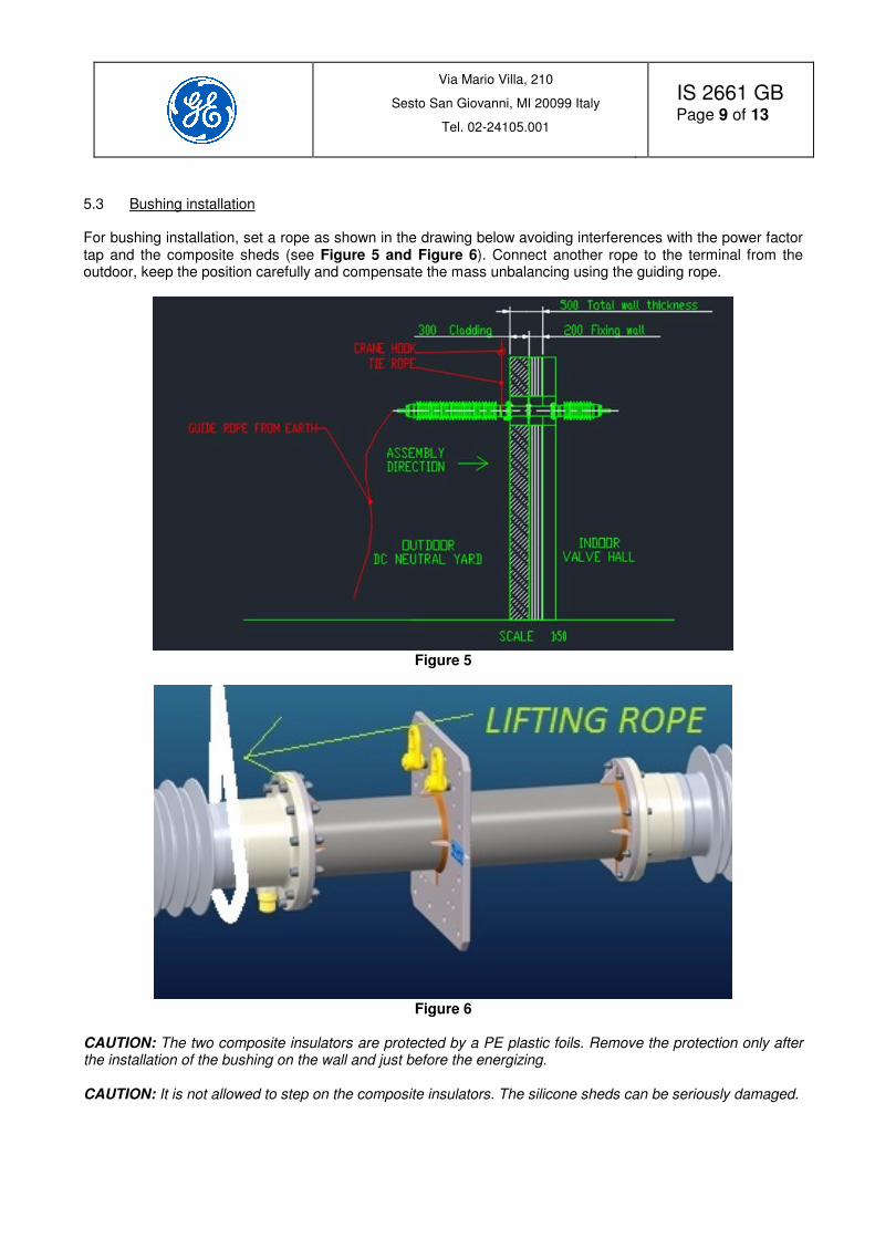
5.3 Bushing installation For bushing installation, set a rope as shown in the drawing below avoiding interferences with the power factor tap and the composite sheds (see Figure 5 and Figure 6). Connect another rope to the terminal from the outdoor, keep the position carefully and compensate the mass unbalancing using the guiding rope.
Figure 5
Figure 6
CAUTION: The two composite insulators are protected by a PE plastic foils. Remove the protection only after the installation of the bushing on the wall and just before the energizing. CAUTION: It is not allowed to step on the composite insulators. The silicone sheds can be seriously damaged.

Via Mario Villa, 210
Sesto San Giovanni, MI 20099 Italy
Tel. 02-24105.001
IS 2661 GB
Page 10 of 13
6 Power factor tap The bushing is equipped with one PF tap, used for capacitance, tan-delta and partial discharge measurements during the tests. In operation it must be accurately closed with its metal cap that ensures also the grounding connection.
Figure 7 – Power factor tap CAUTION: PF tap cap MUST be accurately closed. Missing the cap could be dangerous and it can cause an electrical discharge at bushing energization.
7 Composite insulators maintenance Composite insulators manufactured by qualified and experienced suppliers, require very limited maintenance. The silicone used for the sheds is highly hydrophobic and it has the property to transfer this characteristic to the pollution layer. For this reason, it is not necessary to proceed with frequent washing operation which may progressively weaken the ability of silicone to regenerate its hydrophobicity. Washing must be done only when strictly necessary, i.e. in case of a heavy pollution of the composite insulator. Keep in mind that after washing, the silicone recovers its hydrophobicity in one or two days. The composite insulator maintenance and repair procedure is described into the component manual: see reference in the summary prepared for the specific wall bushing. The composite manufacturer can provide a repairing kit and also a technical support for the repairing activity. Useful indications about the composite insulator maintenance plan main actions are shown in Error! Reference source not found.1. CAUTION: Severe electrical shock risks deriving by the fact that the composite insulator and the other main parts of the bushing remain electrically charged at high voltage for a long period of time after the plant de-energizing and the bushing grounding. Before starting any work on the de-energized bushing, check the discharge by touching all surface of both indoor and outdoor side composite insulators and all other parts of the bushing with an insulated grounding rod which length must be ≥ 3m. Operators must wear protective insulating gloves and boots and helmet with protective transparent face shield. CAUTION: Bushing washing must be performed with the bushing de-energized. Live washing is not allowed due to the high risk of fatal electrical shocks and dangerous flashovers across the composite insulator. CAUTION: Inspection of indoor side of the bushing with the plant energized must be done by qualified technicians, fully in accordance with the safety rules specific for the access to the valve hall. It is recommended to perform all Table 1 listed actions, as a reference starting point, at the first bushing energizing.
Grounding cap
Spring loaded contact
PF tap insulator
Contact pin

Via Mario Villa, 210
Sesto San Giovanni, MI 20099 Italy
Tel. 02-24105.001
IS 2661 GB
Page 11 of 13
Time base
Vis
ual
insp
ecti
on
UV
cam
era
an
d
infr
are
d
exam
inati
on
Wett
ab
ilit
y
6 Months X 1 Year X X When plant is off X X
Table 1 - Composite insulator maintenance plan
Visual inspection: Carefully check that the composite insulators sheds do not show any mechanical damages and significant tracking or erosion due to electrical stress. Visually evaluate also the pollution status and identify the areas of concentrated contamination. Take note of the position of the areas of evidences, to be carefully analysed and taken under control during future inspections. In case of evidence of incipient erosion / tracking, plan an immediate washing action. UV camera and infrared examination: Scan all the surface of the composite insulators with an UV camera to identify possible areas of intense UV emissions on the sheds, on the toroid and the incoming line cables. To perform this test, the camera must be properly set in order to avoid false signals and background noise. In addition, an infrared scan on the line terminal and the incoming cables can reveal incipient hot spots phenomenon that can evolve into a serious damage on the electrical connection and then of the bushing itself. In case of significant variation of the UV and IR emission, plan the following actions: UV emission: Immediate washing action on the interested part, in the meanwhile control all electrical connections. IR emission: Immediate control of all electrical connections. Wettability: The hydrophobicity of the composite insulator can be checked by following the methodology described in IEC TS 62073 – 2003 Guidance on the measurement of wettability on insulator surfaces. The simplest way to assess the wettability is the Method C - Spray method. Wettability level up to WC4 is acceptable for normal operation. In case of further degradation of wettability level (WC5 and WC6) proceed with an accurate washing and drying and then repeat the test. If wettability remains low but there are no evidences of tracking or erosion keep the bushing in operation but follows the intensive maintenance plan of Table 2. .

Via Mario Villa, 210
Sesto San Giovanni, MI 20099 Italy
Tel. 02-24105.001
IS 2661 GB
Page 12 of 13
Time base
Vis
ual
insp
ecti
on
UV
cam
era
an
d
infr
are
d
exam
inati
on
Wett
ab
ilit
y
3 Months X 1/2 Year X X When plant is off X X
Table 2 – Composite insulator intensive maintenance plan
8 General maintenance plan The general maintenance plan is described in the next Table 3.
Component Time base Description Notes
Composite insulators See chapter 7 Inspection and maintenance See chapter 7
Toroid When plant is off Clean the surface and check for scratches or deformation. Check the fixing bolts to the flanges.
Anticipate the controls if UV camera reveals corona inception.
Current terminals and head plates
When plant is off
Check for evidence of hot spots. Check the terminals and tighten the connecting bolts to the bushing flange. Check the cable clamps and the bolting to the terminal.
Anticipate the controls if IR camera reveals hot spots. Contact GE Grid Solutions RPV in case of evidence of hot spots during the inspection.
Grounding terminals When plant is off
Check for evidence of hot spots. Check the connection integrity and the bolt locking. Verify the effectiveness of the grounding.
Contact GE Grid Solutions RPV in case of evidence of hot spots.
Bushing locking to the wall
When plant is off Check that all bolts are properly locked to the wall support.
Power factors taps When plant is off
Open the taps and clean inside. Check the internal spring-loaded contact and clean it. Perform a Megger 1 kV insulation test Rins > 1 MOhm. Carefully close and tighten the cap.
CAUTION: PF tap cap MUST be accurately closed. Missing the cap could be dangerous and it can cause an electrical discharge at bushing energization.
Table 3 – Bushing general maintenance plan

Via Mario Villa, 210
Sesto San Giovanni, MI 20099 Italy
Tel. 02-24105.001
IS 2661 GB
Page 13 of 13
9 Disposal at the end of life At the end of the bushing operative life all parts can be recycled or disposed as follows in Table 4.
Part Material Action
Central flange Aluminium Dispose or thermo-destruction
Indoor and outdoor side flanges Aluminium Dismount and recycle
Toroid – External shields Aluminium Dismount and recycle
Composite insulators with flanges
Fibreglass Dispose or thermo-destruction
Silicone Dispose or thermo-destruction
Aluminium Dispose or thermo-destruction
Central winding core Resin Dispose or thermo-destruction
Terminals Aluminium Dispose or thermo-destruction
Gaskets EPDM rubber Dispose or thermo-destruction
Polyurethane Polymeric Dispose or thermo-destruction
Table 4 – Disposal at the end of life