assembly of westminster summerhouse - sheds, garden sheds, log
TRANSCRIPT
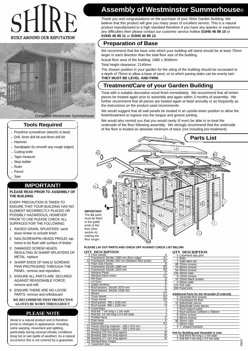
Assembly of Westminster Summerhouse©
Thank you and congratulations on the purchase of your Shire Garden Building. We believe that this product will give you many years of excellent service. This is a natural product manufactured to a high standard therefore if you have any queries or experience any difficulties then please contact our customer service hotline 01945 46 89 10 or01945 46 89 11 or 01945 46 89 12.
Preparation of BaseWe recommend that the base onto which your building will stand should be at least 75mm larger in each direction than the total floor size of the building. Actual floor area of the building: 1980 x 3040mmTotal height clearance: 2140mmThe chosen position in your garden for the siting of the building should be excavated toa depth of 75mm to allow a base of sand, on to which paving slabs can be evenly laid - THEY MUST BE LEVEL AND FIRM.
Treatment/Care of your Garden BuildingTreat with a suitable decorative wood finish immediately. We recommend that all timber pieces be treated again prior to assembly and again within 3 months of assembly. We further recommend that all pieces are treated again at least annually or as frequently as the instructions on the product used recommends.We would suggest that all wall panels be treated in an upside-down position to allow the finish/treatment to ingress into the tongue and groove jointing.We would also remind you that you would rarely (if ever) be able to re-treat the underside of the floor following assembly. We strongly recommend that the underside of the floor is treated an absolute minimum of twice (not including pre-treatment).
Completed Westminster Summerhouse
Tools RequiredPosidrive screwdriver (electric is best)Drill, 6mm drill bit and 8mm drill bitHammerSandpaper (to smooth any rough edges)Cutting knifeTape measureStep ladderRulerPencilSaw
IMPORTANT!PLEASE READ PRIOR TO ASSEMBLY OFTHE BUILDINGEVERY PRECAUTION IS TAKEN TOENSURE THAT YOUR BUILDING HAS NOELEMENT INCORRECTLY PLACED ORPOSSIBLY HAZARDOUS, HOWEVERPRIOR TO USE PLEASE CHECK ALLSURFACES FOR THE FOLLOWING:1 RAISED GRAIN, SPLINTERS: sand
down timber to smooth finish2 NAIL/SCREW/PIN HEADS PROUD: tap
home to be flush with surface of timber3 DAMAGED SCREW HEADS
RESULTING IN SHARP SPLINTERS OFMETAL: replace
4 SHARP ENDS OF NAILS/ SCREWS/PINS PROTRUDING THROUGH THEPANEL: remove and reposition.
5 ENSURE ALL PARTS ARE SECUREDAGAINST REASONABLE FORCE:remove and refit
6 ENSURE THERE ARE NO LOOSEPARTS: remove and refit/discard
WE RECOMMEND THAT PROTECTIVEGLOVES BE WORN THROUGHOUT
QTY DESCRIPTION3 Floor panels A2 Framework 34x46x 1980 mm (floor edge) A1
10 Framework 34x46x 345 mm (between floor joists) A26 Plain Side Panels B2 Framework 44x44x 1980 mm B34 Framework 34x34x 1620 mm B42 Window Panel C2 Window frame insert C13 RH Door D1 LH Door E2 Gable sections F4 Roof bearers 34x34x 2070 mm G2 Roof bearers 34x34x 1036 mm G4 Blocks G12 Truss 44x44 G24 Truss 44x44 G36 Roof panels 795 x 1105 mm H2 Roof panels 985 x 1105 mm H9 Coverstrips I1 Roll felt 7 mtr long x 1 mtr wide J1 Roll felt 3.5 mtr long x 0.5 mtr wide J2 Profiled facia K2 Plain facia K2 Diamonds K1
12 Panes Glazing material – 268 x 373 mm L12 Panes Glazing material – 323 x 373 mm L12 Beading 270 mm long approx M24 Beading 325 mm long approx M48 Beading 377 mm long approx M10 Window/door hinges2 Casement stay
PLEASE LAY OUT PARTS AND CHECK OFF AGAINST CHECK LIST BELOW:
Wood is a natural product and is thereforeprone to changes in appearance, includingsome warping, movement and splitting,particularly during unusual climatic conditions(long hot or wet spells of weather). As a naturaloccurrence this is not covered by a guarantee.
PLEASE NOTE
BUI T AROUND OUR REPUTATION
QTY DESCRIPTION4 Casement stay pins2 Bolts1 Gate latch set
88 25mm screws74 60mm screws54 80mm screws
134 40mm nails8 10mm screws
10 25mm black screws4 50mm nails
170 Felt nails168 Panel pins
Additional Parts for the Verandah (if ordered)5 Verandah floor boards5 Framework for floor
10 Balustrade pieces2 Balustrade cover pieces2 Roof support poles2 Roof sections 1105mm x 336mm8 25mm screws4 80mm screws
98 40mm nails2 60mm nails4 ‘L’ shaped brackets
Felt for Building and Verandah is now:1 Roll felt 8 mtr long x 1 mtr wide1 Roll felt 4 mtr long x 0.5 mtr wide
Parts List
D
D
B3
H3
H
G
G2G2G3 G3
G1
J
J
H H
H2
B3
B4B4
B4
F
L1F
K
K1 K1
K
A
A1
A2
A
I
I
I
B
B
B
B
D
D BL
MC
C1
09/0
7
IMPORTANT. The A1 parts must be fitted to the gable ends of the floor (See section A) making the floor longer.

Assembly of Building - PLEASE READ INSTRUCTIONS PRIOR TO ASSEMBLY
B - Fit Window Insert C1 (from top)
1Place one hinge on the innerrebate part of the top of the window. The rounded part of the hinge should sit above the outer edge of the window. Screw the inner piece into position using the pre drilled holes in the hinge and 2x 25mm screws. Repeat.
A - Floor Assembly
1 Take one floor panel 'A' and a piece of framework 34x46x1980 mmapprox 'A1'. Place the framework on the OPEN edge of the floor so that the framework is flush and level withthe boarding and joists. Look where the floor joist meet the framework and mark. Drill at these marks. Secure to floor using 6x 60 mm screws.
2. Repeat item 1with onemore floorsection.
3. Place floors on your firm levelbase, board side up. Take 5 pieces framework 'A2', 34x46x345 'A2'and place between each floor joist. Nail half of thewidest part tothe floor using3x 40 mm nailsper piece.
4. Once allframeworksare fittedbetweenfloor joistsslide anotherfloor on top of the framework and secure again using 3x 40 mm nails per floor joist.
2Place the window into the aperture. Secure the window to the panel using 3x 25mm screws per hinge, again through the predrilled holes in the hinge. Repeat.
3Open the window and fit a further 2x 25mm screws per hinge next to the one already fitted in Step 1. Repeat.
5Fit theCasementStay on thewindow using2x 25mm screws.
6Mark where the ‘pins’ will be placed.
7Secure into position using 4x 25mm screws - 2 in each pin.
4Fitting theCasementStay. Placethe casementstay centrallyon the inside of the window. Place the 2 pins under the casement stay. Position so that it is not resting on the framework of the panel and not so high that the pins are of no use.
E - Wall Assembly
F - Gable Assembly
1. Decide where the window panel is to go. Place one side panel 'B' on the floor at the right hand corner.Place a further panel 'B' inside the panel already in place. THEPANELS ALONG THE BACKWALL SHOULD EXTEND FROMFLOOR EDGE TO FLOOR EDGE. The panels to go at the side screwTO and fit INSIDE the panels to go at the back.
2. Drill 2 holes, one to the top andone to the bottom. Do not drill into adjacent panels. Secure thepanels together using 2x 60 mm screws.
3. Repeat for all plain side panels and also complete front assembly.
1. Put floor on firm level base, then assemble front on floor.
2. Three ‘doors’ are the same, one is different. Two of the three are theouter ‘wing’ panels ‘D’. Take oneand add one piece of 44x44 x 1620 mm long to both long sides. Position centrally along edge leaving an equal gap at the top and bottom.
3. Take 2 pieces 44x44x 1980 mmand 2 pieces 44x44 x 1620 mm.Lay out as a frame the long piecestop and bottom. Place the shortpieces inside the longer pieces.Drill/screw through the corner of thelonger piece into the short pieceusing 1x 80 mm screw. Repeat atother end and at other side.
4. Place one of the 3 ‘doors’ ‘D’ in the left hand side of the frame. Takeanother piece of 1620 mm frame and place under and tight to the ‘door’. Drill/screw into position using 1x 80 mm screw at each end.Place ‘door’ ‘D’ centrally in gap.Drill 4 guide holes along the length of the outer frame, repeat on inner frame. Secure ‘door’ into position using 4x 80 mm in each post. Repeat at other side.
5. Three hinges ‘C2’ need to spaced along the door – one centrally, one towards the top and one toward the bottom. Place one hinge ‘C2’ on the inner rebated part of the edgeof one door ‘E’. Screw the inner piece of one into position using the pre drilled holes in the hinge and2x 25 m screws. Repeat for the hinges on each door.
6. Place the doors ‘D’ & ‘E’ on thefloor of the building facing upwards. Place ‘door’ assembly on top of the doors so that the doors fit insidethe aperture.
7. Secure the doors to the panelusing 1x 25 mm screw per hinge through the predrilled centre holes of each hinge. Repeat for all hinges.
1. Place one gablesection 'F' on top of the backwalls. Drill 4 times along the length and secure using 4x 60 mm screws.
2. Repeat at front.
G - Fiting Trusses
C - Front Assembly
1. Take one small block ‘G1’ with one end angled and the other square. Drill through the bock twice. Repeat with other block.
2 Measure and mark 75 mm from top of framework of adjoining sidepanels. Place the block flush to theframework of one side panel. The lower part of the angled part of theblock ‘G1’ should be placed on the mark. Screw into position using 2x 80 mm screws. Repeat.
3 Drill through the top of the trussapprox 2 cm from the outer edge. Place the truss on top of two opposite blocks and secure using 1x 80 mm screw at each side. Repeat.
D - Truss Assembly
1 Using a gable (part F pack A) as a template lay two pieces of truss (G2) and one piece of truss (G3) on top of the gable to form an ‘A’shape. This is so you can get the correct angle for your truss.
2 Drill/ Screw truss at the ridge using 2 x 80mm screws.
3 Drill/ Screw bracing bar (G3) into (G2) using 2 x 80mm screws ateach end.
4 Secure to the backgable using 3x 40mm nails into eachgable.
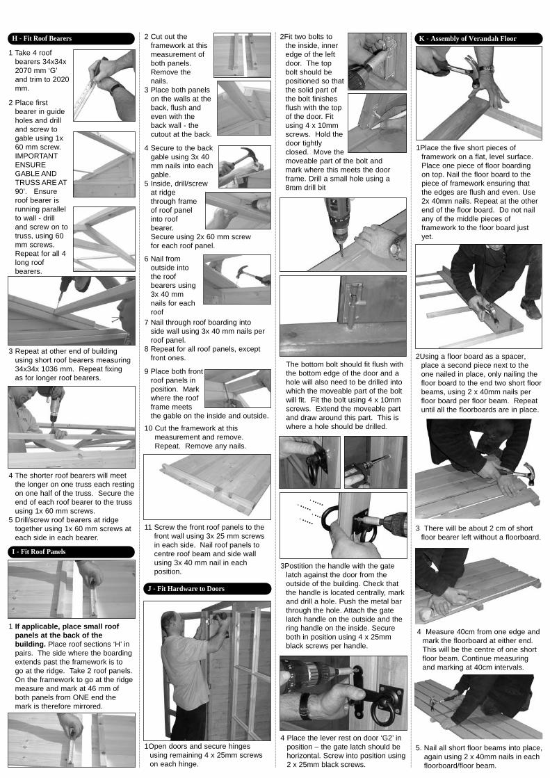
5 Inside, drill/screwat ridgethrough frameof roof panelinto roofbearer.Secure using 2x 60 mm screw for each roof panel.
K - Assembly of Verandah Floor
1Place the five short pieces of framework on a flat, level surface. Place one piece of floor boarding on top. Nail the floor board to the piece of framework ensuring that the edges are flush and even. Use 2x 40mm nails. Repeat at the otherend of the floor board. Do not nail any of the middle pieces of framework to the floor board justyet.
2Using a floor board as a spacer, place a second piece next to the one nailed in place, only nailing the floor board to the end two short floor beams, using 2 x 40mm nails per floor board per floor beam. Repeat until all the floorboards are in place.
5. Nail all short floor beams into place, again using 2 x 40mm nails in eachfloorboard/floor beam.
3 There will be about 2 cm of shortfloor bearer left without a floorboard.
4 Measure 40cm from one edge and mark the floorboard at either end. This will be the centre of one short floor beam. Continue measuring and marking at 40cm intervals.
2Fit two bolts tothe inside, inneredge of the leftdoor. The topbolt should bepositioned so thatthe solid part ofthe bolt finishesflush with the topof the door. Fitusing 4 x 10mmscrews. Hold thedoor tightlyclosed. Move themoveable part of the bolt and mark where this meets the door frame. Drill a small hole using a 8mm drill bit.
11 Screw the front roof panels to the front wall using 3x 25 mm screws in each side. Nail roof panels tocentre roof beam and side wall using 3x 40 mm nail in each position.
10 Cut the framework at thismeasurement and remove. Repeat. Remove any nails.
9 Place both frontroof panels inposition. Markwhere the roofframe meetsthe gable on the inside and outside.
7 Nail through roof boarding into side wall using 3x 40 mm nails per roof panel.
8 Repeat for all roof panels, except front ones.
6 Nail fromoutside intothe roofbearers using3x 40 mmnails for eachroof
The bottom bolt should fit flush with the bottom edge of the door and a hole will also need to be drilled into which the moveable part of the bolt will fit. Fit the bolt using 4 x 10mm screws. Extend the moveable partand draw around this part. This is where a hole should be drilled.
3Postition the handle with the gate latch against the door from the outside of the building. Check that the handle is located centrally, mark and drill a hole. Push the metal bar through the hole. Attach the gate latch handle on the outside and the ring handle on the inside. Secure both in position using 4 x 25mm black screws per handle.
4 Place the lever rest on door ‘G2’ in position – the gate latch should behorizontal. Screw into position using 2 x 25mm black screws.
J - Fit Hardware to Doors
I - Fit Roof Panels
2 Cut out theframework at this measurement of both panels. Remove thenails.
3 Place both panelson the walls at the back, flush and even with the back wall - the cutout at the back.
1 If applicable, place small roof panels at the back of thebuilding. Place roof sections ‘H’ inpairs. The side where the boardingextends past the framework is to go at the ridge. Take 2 roof panels.On the framework to go at the ridge measure and mark at 46 mm of both panels from ONE end themark is therefore mirrored.
1Open doors and secure hinges using remaining 4 x 25mm screws on each hinge.
2 Place firstbearer in guide holes and drill and screw to gable using 1x 60 mm screw. IMPORTANT ENSUREGABLE AND TRUSS ARE AT90’. Ensure roof bearer is running parallel to wall - drilland screw on to truss, using 60 mm screws. Repeat for all 4 long roof bearers.
3 Repeat at other end of buildingusing short roof bearers measuring 34x34x 1036 mm. Repeat fixing as for longer roof bearers.
4 The shorter roof bearers will meetthe longer on one truss each resting on one half of the truss. Secure the end of each roof bearer to the truss using 1x 60 mm screws.
5 Drill/screw roof bearers at ridgetogether using 1x 60 mm screws at each side in each bearer.
1 Take 4 roofbearers 34x34x 2070 mm ‘G’ and trim to 2020mm.
H - Fit Roof Bearers
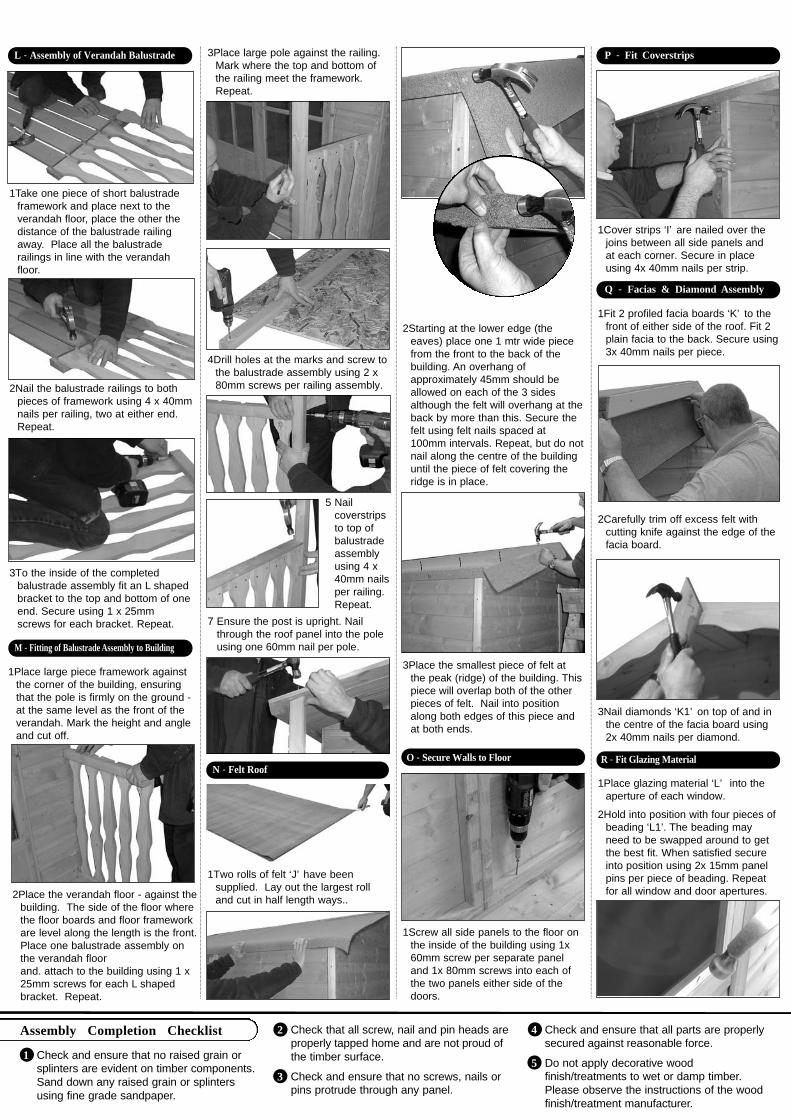
1 Check and ensure that no raised grain or splinters are evident on timber components.Sand down any raised grain or splinters using fine grade sandpaper.
2 Check that all screw, nail and pin heads are properly tapped home and are not proud ofthe timber surface.
3 Check and ensure that no screws, nails or pins protrude through any panel.
4 Check and ensure that all parts are properly secured against reasonable force.
5 Do not apply decorative wood finish/treatments to wet or damp timber.Please observe the instructions of the wood finish/treatment manufacturer.
Assembly Completion Checklist
3Place the smallest piece of felt atthe peak (ridge) of the building. This piece will overlap both of the otherpieces of felt. Nail into position along both edges of this piece and at both ends.
2Starting at the lower edge (the eaves) place one 1 mtr wide piece from the front to the back of the building. An overhang of approximately 45mm should be allowed on each of the 3 sides although the felt will overhang at the back by more than this. Secure the felt using felt nails spaced at100mm intervals. Repeat, but do not nail along the centre of the building until the piece of felt covering the ridge is in place.
1Screw all side panels to the floor on the inside of the building using 1x 60mm screw per separate panel and 1x 80mm screws into each of the two panels either side of the doors.
O - Secure Walls to Floor
Q - Facias & Diamond Assembly
1Fit 2 profiled facia boards ‘K’ to the front of either side of the roof. Fit 2 plain facia to the back. Secure using 3x 40mm nails per piece.
P - Fit Coverstrips
1Cover strips ‘I’ are nailed over the joins between all side panels and at each corner. Secure in place using 4x 40mm nails per strip.
2Carefully trim off excess felt with cutting knife against the edge of the facia board.
3Nail diamonds ‘K1’ on top of and in the centre of the facia board using 2x 40mm nails per diamond.
R - Fit Glazing Material
1Place glazing material ‘L’ into the aperture of each window.
2Hold into position with four pieces of beading ‘L1’. The beading mayneed to be swapped around to get the best fit. When satisfied secure into position using 2x 15mm panel pins per piece of beading. Repeat for all window and door apertures.
N - Felt Roof
1Two rolls of felt ‘J’ have been supplied. Lay out the largest roll and cut in half length ways..
1Place large piece framework against the corner of the building, ensuring that the pole is firmly on the ground - at the same level as the front of the verandah. Mark the height and angle and cut off.
2Place the verandah floor - against the building. The side of the floor where the floor boards and floor framework are level along the length is the front. Place one balustrade assembly on the verandah floorand. attach to the building using 1 x 25mm screws for each L shaped bracket. Repeat.
4Drill holes at the marks and screw to the balustrade assembly using 2 x 80mm screws per railing assembly.
M - Fitting of Balustrade Assembly to Building
5 Nail coverstripsto top of balustrade assembly using 4 x 40mm nails per railing. Repeat.
3Place large pole against the railing. Mark where the top and bottom of the railing meet the framework. Repeat.
7 Ensure the post is upright. Nailthrough the roof panel into the pole using one 60mm nail per pole.
2Nail the balustrade railings to both pieces of framework using 4 x 40mm nails per railing, two at either end. Repeat.
3To the inside of the completed balustrade assembly fit an L shaped bracket to the top and bottom of one end. Secure using 1 x 25mm screws for each bracket. Repeat.
1Take one piece of short balustrade framework and place next to the verandah floor, place the other the distance of the balustrade railing away. Place all the balustrade railings in line with the verandah floor.
L - Assembly of Verandah Balustrade