richard e. kingston
TRANSCRIPT

MFN 09-307 Docket No. 52-010 May 11, 2009 U.S. Nuclear Regulatory Commission 11555 Rockville Pike Document Control Desk Rockville, MD 20852 Subject: Response to Portion of NRC Request for Additional Information
Letter No. 334 Related to ESBWR Design Certification Application – Site Characteristics - RAI Number 2.3-4 S05
The purpose of this letter is to submit the GE Hitachi Nuclear Energy (GEH) responses to the U.S. Nuclear Regulatory Commission (NRC) Request for Additional Information (RAIs) sent by NRC letter No. 334, dated April 16, 2009 (Reference 1). GEH response to RAI 2.3-4 S05 is provided in Enclosure 1. Enclosure 2 provides any affected DCD Sections. Sincerely,
Richard E. Kingston Vice President, ESBWR Licensing
GE Hitachi Nuclear Energy Richard E. Kingston Vice President, ESBWR Licensing
PO Box 780 3901 Castle Hayne Road, M/C A-65 Wilmington, NC 28402 USA T 910 819 6192 F 910 362 6192

MFN 09-307 Page 2 of 2
Reference:
1. MFN 09-274 - Letter from U.S. Nuclear Regulatory Commission to Mr. Jerald G. Head, GEH, Request For Additional Information Letter No. 334 Related To ESBWR Design Certification Application, dated April 16, 2009
Enclosure:
1. MFN 09-307 -Response to NRC Request for Additional Information Letter No. 334 Related to ESBWR Design Certification Application – DCD Tier 2 Chapter 2 - Site Characteristics - RAI Number 2.3-4 S05
. 2. MFN 09-307 -Response to NRC Request for Additional Information Letter
No. 334 Related to ESBWR Design Certification Application – DCD Tier 2 Chapter 2 – Site Characteristics - RAI Number 2.3-4 S05DCD Markups.
cc: AE Cubbage USNRC (with enclosure)
JG Head GEH/Wilmington (with enclosure) DH Hinds GEH/Wilmington (with enclosure) RM Wachowiak GEH/Wilmington (with enclosure) EDRF Section 0000-0101-7519 (RAI 2.3-4 S05)

ENCLOSURE 1
MFN 09-307
Partial Response to NRC RAI Letter No. 334 Related to ESBWR Design Certification Application1
DCD Tier 2 Chapter 2 – Site Characteristics
RAI Number 2.3-4 S05
1 Original Response, Supplement 1, Supplement 2, Supplement 3 and Supplement 4 previously submitted under MFNs 06-206, 06-206 S01, 07-628, 08-076 and 08-919 without DCD updates are included to provide historical continuity during review.

MFN-09-307 Page 1 of 11 Enclosure 1
NRC RAI 2.3-4
What is the basis for the maximum rainfall rate and maximum snow load for the roof design given in DCD tier 2, Table 2.0-1? Is the maximum rainfall rate assumed to be over a period of five minutes?
GE Response
The maximum rainfall rate and maximum snow loads were taken from the Advanced Light Water Reactor Utility Requirements Document (URD), Volume III, Table 1.2-6. These values are also the same as those that were applied during design certification of the Advanced Boiling Water Reactor (ABWR).
As Indicated in the text of Table 2.0-1 for Subsection 2.3.1, the maximum rainfall rate in the URD was obtained from National Weather Service Publication HMR No. 52 using the probable maximum precipitation (PMP) for 1 hour over a 2.6x10⁶ m2 (1 sq. mile) area with a PMP ratio of 5 minutes to 1 hour of 0.32.
DCD Impact
A markup of DCD Table 2.0-1 to clarify that the URD is the source of these values was provided in MFN 06-206.

MFN-09-307 Page 2 of 11 Enclosure 1
NRC RAI 2.3-4 S01
E-mail from Andrea Johnson.
Comments on response to RAI 2.3-4:
This RAI addresses the design values and bases for winter precipitation loads to be included in the combination of (1) normal live loads and (2) extreme live loads.
Tier 1 Table 5.1-1 and Tier 2 Table 2.0-1 of DCD Revision 3 state that the maximum design roof load of 2873 Pa (60 lbf/ft2) accommodates snow load and probable maximum winter precipitation as specified in ASCE 7-02 and HMR-52. The March 24, 1975 Site Analysis Branch Position on Winter Precipitation Loads (ML050470024) states that (1) winter precipitation loads to be included in the combination of normal live loads should be based on the weight of the 100-year snowpack or snowfall, whichever is greater, recorded at ground level, and (2) winter precipitation loads to be included in the combination of extreme live loads should be based on the addition of the weight of the 100-year snowpack at ground level plus the weight of the 48-hour Probable Maximum Winter Precipitation (PMWP) at ground level for the month corresponding to the selected snowpack. Modifications to this procedure are allowed for certain areas where it can be satisfactorily demonstrated that the PMWP could neither fall nor remain entirely on top of the antecedent snowpack and/or roofs.
Consequently, please update the DCD to provide the design values and bases for winter precipitation loads to be included in the combination of (1) normal live loads and (2) extreme live loads. Note that the 48-hour PMWP should be based on data presented in HMR-53.
GE Response The roof load design bases for concrete structures is 2873 Pa (60 psf) which is multiplied by the Load Factors indicated depending on the particular combination and is combined with other loads as shown on DCD Table 3.8-15.
The rain and snow loads are described in Section 3G.1.5.2.1.2.
The live load represents a 100-year return ground snow load of 2394 Pa (50 psf) that on the roof is 60% of that based on exposure and thermal conditions (ASCE 7 Commentary). Therefore, the basic roof snow load is 1436 Pa (30 psf). The lower lip of roof scuppers is 100 mm (4 in) above the roof and assuming all primary roof drains are clogged, this added load is 996 Pa (21 psf).
The PMWP is based on the 48-hour PMWP in HMR 53 Section 6 example calculation for December, January, February and the drainage system (roof drains and scuppers independently) will be sized accordingly. Therefore, the total maximum conservative loading (rain + snowpack) would be 2442 Pa (51 psf), which is less than the design live load of 2873 Pa (60 psf).
DCD Impact A markup of DCD Tier 2 Table 3G.1-2 to clarify that the ground snow load represents a 100-year recurrence interval was provided in MFN 06-206, Supplement 1.

MFN-09-307 Page 3 of 11 Enclosure 1
NRC RAI 2.3-4 S02
In its response to supplemental RAI 2.3-4 dated May 8, 2007, the applicant stated that the roof design maximum 48-hr. winter rainfall standard plant site design parameter of 91.4 cm (36 in.) would result in an additional weight of 10 cm (4 in.) of water on the roof because the lower lip of the roof scuppers is 10 cm (4 in.) above the roof. Assuming all primary roof drains are clogged, the additional weight of water on the roof would be 996 Pa (21 psf). However, the applicant should also provide an additional roof design 48-hour probable maximum winter precipitation (PMWP) standard plant design parameter to account for the additional weight if at least part of the 48-hour PMWP falls as frozen precipitation (e.g., snow and/or ice) and therefore remains on the roof.
GEH Response
As stated in our response to NRC RAI 2.3-4 S01, total conservative loading for rain plus snowpack for the ESBWR Standard Plant is 2442 Pa (51 psf), which is less than the design live load of 2873 Pa (60 psf) at the roof. This design live load is specified in DCD Tier 2, Revision 4, Table 2.0-1 as the ESBWR Standard Plant Site Parameter of Maximum Roof Load. Thus, a margin of 431 Pa (9 psf) is provided for any additional increase in snow load as rain percolates through the snowpack and potential increase due to frozen precipitation.
Per Section 7.10 of ASCE 7-02, the rain-on-snow surcharge associated with rain percolating through a snowpack is 239 Pa (5 psf). Hence, a margin of 192 Pa (4 psf) remains to account for any frozen precipitation for the ESBWR Standard Plant.
The values for rain-on-snow surcharge and frozen precipitation are not shown individually in DCD Tier 2, Revision 4, Table 2.0-1 as ESBWR Standard Plant Site Parameters because the Maximum Roof Load of 2873 Pa (60 psf) is already specified in DCD Tier 2 Tables 2.0-1 and 3G.1-2. As required in DCD Tier 2, Revision 4, Subsection 2.0.1, Item 2.0.1-A, each COL applicant will demonstrate in their COL application how the site characteristics of 100-year snowpack plus 48-hour PMWP (including frozen precipitation) are combined to fall within the ESBWR DCD site parameter value for Maximum Roof Load.
DCD Impact
No DCD change was made in response to this RAI Supplement.

MFN-09-307 Page 4 of 11 Enclosure 1
NRC RAI 2.3-4 S03
Footnote 5 to DCD Tier 2 Table 2.0-1 states that the roof scuppers and drains are designed independently to limit water accumulation on the roof to no more than 100 mm (4 in) during PMWP conditions. Please provide details of the design of the roof scuppers and drains demonstrating that an antecedent 100-year recurrence interval ground level snow pack of 2394 Pa (50 lbf/ft2) will not clog both the roof scuppers and drains and prevent no more than 100 mm (4 in) of water accumulating on the roof.
GEH Response
In the ESBWR Standard Plant, roofs are provided with two independent drainage systems. The roof drains form the primary drainage system and the scuppers form the secondary drainage system. As required by the International Plumbing Code (invoked by IBC-2003) and ASCE 7-02, only the blockage of the primary system is postulated when designing the secondary system and for calculating the rain load on the roof.
Figures 2.3-4(1) and (2) show typical sketches of the roof drain and overflow scupper. The design of the roof scuppers and drains follows ASCE 7-02. The elevation of the overflow scupper is set such that the average water depth does not exceed 100 mm (4 in.) in case the roof drains are clogged by snow, ice, or other obstructions.
DCD Tier 2 Table 2.0-1, Note 5 and Table 3G.1-2, Note** will be clarified to state that the depth of water considered on the roof is an average depth.
DCD Impact
Markups of DCD Tier 2 Table 2.0-1, Note 5 and Table 3G.1-2, Note** were provided in MFN 08-076.

MFN-09-307 Page 5 of 11 Enclosure 1
Figure 2.3-4(1) Typical Sketch of Roof Drain

MFN-09-307 Page 6 of 11 Enclosure 1
Figure 2.3-4(2) Typical Sketch of Overflow Scupper

MFN-09-307 Page 7 of 11 Enclosure 1
NRC RAI 2.3-4 S04
Specify and identify the normal and extreme liquid and frozen precipitation events used in the design of the roofs of safety related structures in accordance with the Proposed Interim Staff Guidance (ISG) DC/COL-ISG-07, “Interim Staff Guidance on Assessment of Normal and Extreme Winter Precipitation Loads on the Roofs of Seismic Category I Structures.” These events should be identified as site parameters in DCD Tier 1 Table 5.1-1 and Tier 2 Table 2.0-1. Provide a basis for the chosen site parameter values, including ensuring the postulated site parameter values are representative of a reasonable number of sites that have been or may be considered for a COL application. Also describe the design and analysis method used to accommodate the resulting loads.
GEH Response
This NRC RAI addresses the normal and extreme liquid and frozen precipitation events used in the design of the roofs of safety related structures in accordance with the Proposed Interim Staff Guidance (ISG) DC/COL-ISG-07, “Interim Staff Guidance on Assessment of Normal and Extreme Winter Precipitation Loads on the Roofs of Seismic Category I Structures.”
As indicated in DCD Tier 2 Table 2.0-1, the maximum rainfall rate is based on probable maximum precipitation (PMP) for one hour over 2.6 km2
(one square mile) with a ratio of 5 minutes to one hour PMP of 0.32 as found in National Weather Service Publication Hydrometeorology Report No. 52 (HMR-52). The maximum rainfall rate selected for design is 49.3 cm/hr (19.4 in/hr). The maximum short term rate selected is 15.7 cm (6.2 in) in 5 minutes. The roof scuppers and drains are designed independently to handle the PMP or 48-hour probable maximum winter precipitation (PMWP) with no more than an average depth of 100 mm (4 in) of water accumulation on the roof.
Normal winter precipitation event is equal to highest ground-level weight among (1) the 100-year return period snowpack, (2) the historical maximum snowpack, (3) the 100-year return period snowfall event, or (4) the historical maximum snowfall event in the site region. The normal ground snow load of 2394 Pa (50 psf) for a 100-year return period conidered in the DCD Tier 2 Table 2.0-1 envelopes all sites currently being considered for ESBWR COL applications. The corresponding roof load, pf, is calculated to be 38.5 psf in accordance with ASCE 7-02, Equation 7-1.
0.7f e t gp C C Ip=
where
Ce = exposure factor = 1.1 for sheltered roof in Terrain Category C
Ct = thermal factor = 1.0
I = importance factor = 1.0 for 100-year return peiord
Pg = 100-year ground snow load = 50 psf

MFN-09-307 Page 8 of 11 Enclosure 1
This is the roof live load associated with normal winter precipitation event. It is less than the design live load of 2873Pa (60 psf) at the roof considered in all loading combinations for Seismic Category I structures as shown in DCD Tier 2 Tables 3.8-15 and 3.8-16.
The extreme winter precipitation roof load as defined in DC/COL-ISG-07 is the roof load due to the normal winter precipitation event plus the roof load due to the extreme winter precipitation event which is the higher roof load resulting from either the extreme frozen winter precipitation event or the extreme liquid winter precipitation event. The industry comments on this ISG (Reference 1) recommend that the bullet “An additional site characteristic for evaluating extreme load winter precipitation events should be provided to account for additional weight if at least part of the 48-hour PMWP falls as frozen precipitation” on page 4 under “Issues” be deleted. The extreme liquid winter precipitation is associated with the maximum 48-hour winter rainfall as defined in DCD Tier 2 Table 2.0-1. Its effect on the roof is accounted for in a form of an average depth of 4” of water. The resulting liquid weight is 21 psf. The extreme winter precipitation roof load is thus 59.5 psf which is the sum of 38.5 psf for normal winter precipitation and 21 psf for extreme liquid winter precipitation. It is still less than the 60 psf roof design live load. In accordance with the ISG, the extreme winter precipitation roof load is considered as an extreme live load and treated similarly to other extreme environmental loads such as SSE or tornado in loading combinations. In other words the extreme winter precipitation roof load, treated as live load, is combined with other applicable loads excluding SSE or tornado as an additional load combination case for the extreme environmental category in DCD Tier 2 Tables 3-8-15 and 3.8-16. The roof of ESBWR Seismic Category I buildings are designed to a much more severe loading due to SSE or tornado in the extreme environmental load combination category. Take the tornado load for example, the roof is designed to a pressure drop equal to 2.4 psi or 345.6 psf. For the extreme winter precipitation roof load to reach 345.6 psf will require the extreme frozen winter precipitation roof load equal to 307.1 psf (i.e., 345.6-38.5 for normal winter precipitation). This is much higher than any conceivable frozen winter precipitation anywhere. Therfore, the extreme frozen winter precipitation event is not controlling in the ESBWR design.
Reference
1. NEI Letter to NRC, Industry Comments on Interim Staff Guidance on Winter Precipitation Loads for Seismic Category 1 Structures (ISG-7), dated October 15, 2008.
DCD Impact
No DCD change was made in response to this RAI Supplement.

MFN-09-307 Page 9 of 11 Enclosure 1
NRC RAI 2.3-4 S05
In its response to RAI 2.3-4 S04 (MFN 08-919 dated December 8, 2008), GEH assumed weight of 4 inches of water in addition to snow load on roof due to normal winter precipitation for computing extreme winter precipitation roof load. Based on the pictorial layout of the roof drain and the scuppers, the staff could not conclude if the roof scuppers would be available for draining water from roof in case of rain after an antecedent snow fall. In that case, the combined snowpack and water on roof may be as high as the height of the solid parapet, and may be more critical.
Also, while justifying possible roof load due to frozen precipitation during an extreme winter precipitation event, GEH compared the roof design having been done for 345.6 psf load due to tornado pressure drop, and concluded that “the extreme frozen winter precipitation event is not controlling in the ESBWR design.” Since load due to pressure drop acts in a direction opposite to the roof live load, and since dead load of roof is available to offset load due to tornado pressure drop, a direct comparison of these two loads without considering effect due to dead load was not understood. GEH needs to calculate the value of extreme frozen winter precipitation and demonstrate how it is enveloped by other loading combinations.
Accordingly, the staff requests GEH to address the following in the DCD:
1. Identify the normal roof load considering normal winter precipitation event which should be treated as live load in all loading combinations.
2. Identify the extreme roof load considering extreme winter precipitation event.
3. Include in the DCD a loading combination for consideration of the extreme roof load for design, or provide justification why it is not necessary.
GEH Response
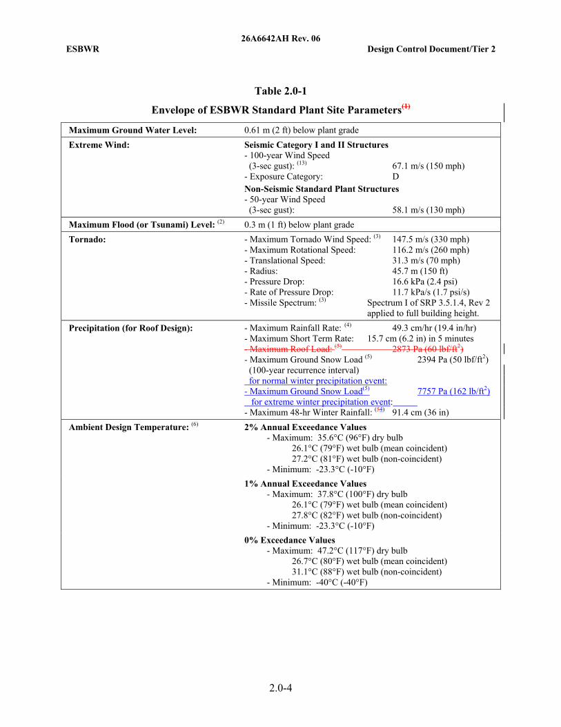
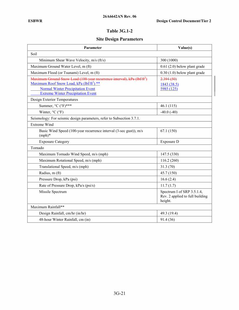
1. The roof load considering a normal winter precipitation event, which should be treated as a normal live load in all loading combinations, is 38.5 lb/ft2, which corresponds to the maximum 50 lb/ft2 ground snow load (100-year recurrence interval) in Revision 5 of DCD Tier 1 Table 5.1-1 and DCD Tier 2 Table 2.0-1. For clarification, the parameter heading “Maximum Ground Snow Load (100-year recurrence interval)” will be changed to “Maximum Ground Snow Load (100-year recurrence interval) for normal winter precipitation event” in Revision 6 of DCD Tier 1 Table 5.1-1 and DCD Tier 2 Table 2.0-1. The maximum roof snow load for the normal winter precipitation event of 38.5 lb/ft2 will be replacing the corresponding maximum ground snow load of 50 lb/ft2 in Revision 6 of DCD Tier 2 Table 3G.1-2.
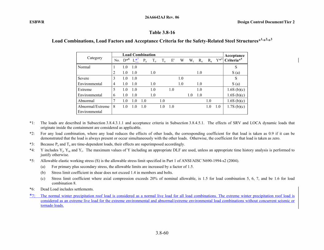
2. The roof load considering an extreme winter precipitation event, which should be treated as an extreme live load in the extreme environmental and abnormal/extreme environmental loading combinations without concurrent seismic and tornado loads, is 125 lb/ft2, and its corresponding ground snow load will be added as a standard plant site parameter in Revision 6 of DCD Tier 1 Table 5.1-1 and DCD Tier 2 Table 2.0-1. The maximum roof
MFN-09-307 Page 10 of 11 Enclosure 1
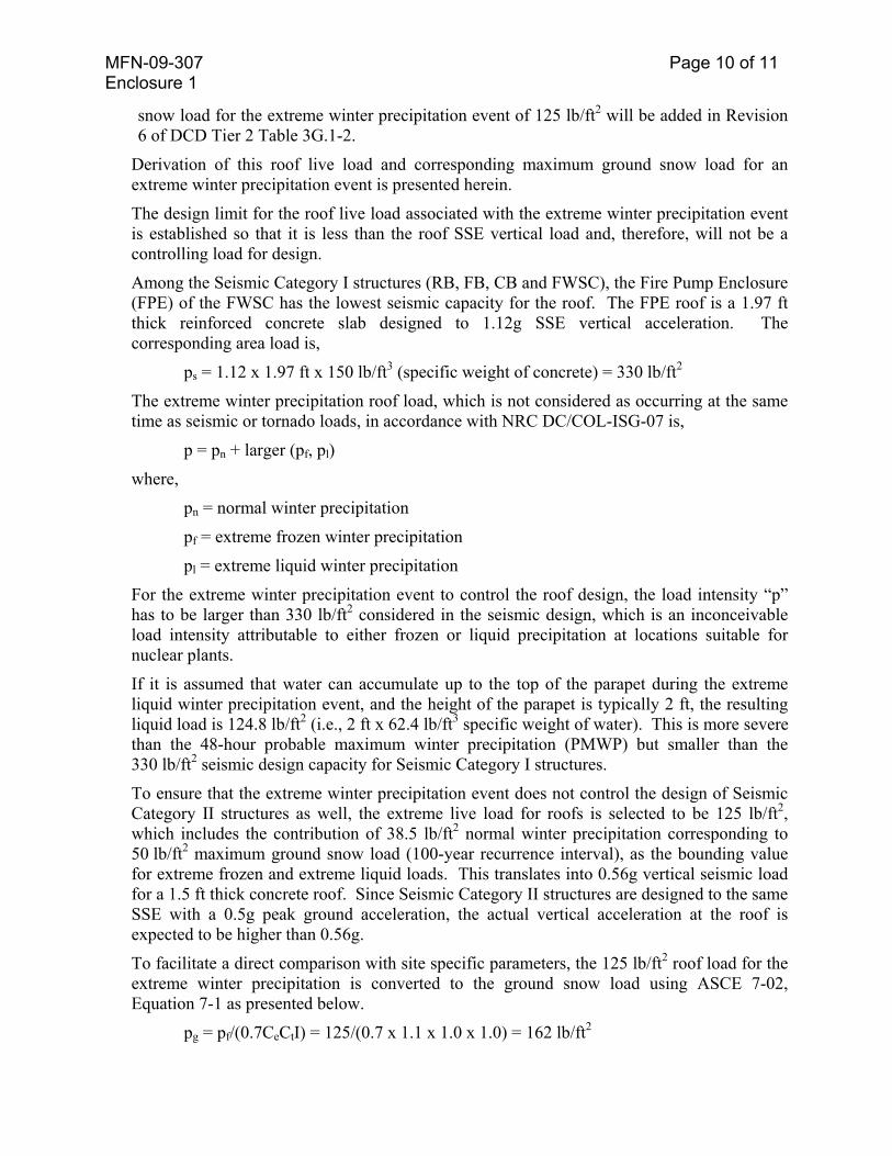
snow load for the extreme winter precipitation event of 125 lb/ft2 will be added in Revision 6 of DCD Tier 2 Table 3G.1-2.
Derivation of this roof live load and corresponding maximum ground snow load for an extreme winter precipitation event is presented herein.
The design limit for the roof live load associated with the extreme winter precipitation event is established so that it is less than the roof SSE vertical load and, therefore, will not be a controlling load for design.
Among the Seismic Category I structures (RB, FB, CB and FWSC), the Fire Pump Enclosure (FPE) of the FWSC has the lowest seismic capacity for the roof. The FPE roof is a 1.97 ft thick reinforced concrete slab designed to 1.12g SSE vertical acceleration. The corresponding area load is,
ps = 1.12 x 1.97 ft x 150 lb/ft3 (specific weight of concrete) = 330 lb/ft2
The extreme winter precipitation roof load, which is not considered as occurring at the same time as seismic or tornado loads, in accordance with NRC DC/COL-ISG-07 is,
p = pn + larger (pf, pl)
where,
pn = normal winter precipitation
pf = extreme frozen winter precipitation
pl = extreme liquid winter precipitation
For the extreme winter precipitation event to control the roof design, the load intensity “p” has to be larger than 330 lb/ft2 considered in the seismic design, which is an inconceivable load intensity attributable to either frozen or liquid precipitation at locations suitable for nuclear plants.
If it is assumed that water can accumulate up to the top of the parapet during the extreme liquid winter precipitation event, and the height of the parapet is typically 2 ft, the resulting liquid load is 124.8 lb/ft2 (i.e., 2 ft x 62.4 lb/ft3 specific weight of water). This is more severe than the 48-hour probable maximum winter precipitation (PMWP) but smaller than the 330 lb/ft2 seismic design capacity for Seismic Category I structures.
To ensure that the extreme winter precipitation event does not control the design of Seismic Category II structures as well, the extreme live load for roofs is selected to be 125 lb/ft2, which includes the contribution of 38.5 lb/ft2 normal winter precipitation corresponding to 50 lb/ft2 maximum ground snow load (100-year recurrence interval), as the bounding value for extreme frozen and extreme liquid loads. This translates into 0.56g vertical seismic load for a 1.5 ft thick concrete roof. Since Seismic Category II structures are designed to the same SSE with a 0.5g peak ground acceleration, the actual vertical acceleration at the roof is expected to be higher than 0.56g.
To facilitate a direct comparison with site specific parameters, the 125 lb/ft2 roof load for the extreme winter precipitation is converted to the ground snow load using ASCE 7-02, Equation 7-1 as presented below.
pg = pf/(0.7CeCtI) = 125/(0.7 x 1.1 x 1.0 x 1.0) = 162 lb/ft2

MFN-09-307 Page 11 of 11 Enclosure 1
where,
Ce = exposure factor = 1.1 for sheltered roof in Terrain Category C
Ct = thermal factor = 1.0
I = importance factor = 1.0
3. DCD Tier 2 Sections 3.8 and 3G will be updated in Revision 6 to document the roof live loads for both normal and extreme winter precipitation events and associated load combinations. Table 2.3-4(1) is a summary of the roof live loads and ground snow loads. Since roof loads are more of a structural design parameter, they will be deleted from the standard plant site parameters in DCD Tier 1 Table 5.1-1 and DCD Tier 2 Table 2.0-1. Since roof scupper and drain design information is more of a structural design issue and is addressed in DCD Tier 2 Table 3G.1-2, Note **, it will be deleted from DCD Tier 2 Table 2.0-1, Notes 4 and 5.
Table 2.3-4(1) Summary of Roof Live Loads and Ground Snow Loads
Roof Live Load Ground Snow Load Event
lb/ft2 Pa lb/ft2 Pa
Normal winter precipitation 38.5 1843 50 2394
Extreme winter precipitation 125 5985 162 7757
DCD Impact
DCD Tier 1 Table 5.1-1 and DCD Tier 2 Table 2.0-1, Table 3.8-15, Table 3.8-16, Table 3G.1-2 and DCD Tier 2 Subsections 2.0.2, 3G.1.5.2.1.2, 3G.2.5.2.1.2, 3G.3.5.2.1.2 and 3G.4.5.2.1.2 will be revised as noted in the attached markups.

MFN 09-307
Enclosure 2
Response to NRC Request for Additional
Information Letter No. 334 Related to ESBWR Design Certification Application –
DCD Tier 2 Chapter 2 – Site Characteristics
RAI Number 2.3-4 S05 DCD Markups

26A6641AB Rev. 06 ESBWR Design Control Document/Tier 1
5.1-2
Table 5.1-1
Envelope of ESBWR Standard Plant Site Parameters (1)
Maximum Ground Water Level: 0.61 m (2 ft) below plant grade Extreme Wind: Seismic Category I and II Structures
- 100-year Wind Speed (3-sec gust): 67.1 m/s (150 mph) - Exposure Category: D Non-Seismic Standard Plant Structures - 50-year Wind Speed (3-sec gust): 58.1 m/s (130 mph)
Maximum Flood (or Tsunami) Level: 0.3 m (1 ft) below plant grade Tornado: - Maximum Tornado Wind Speed: 147.5 m/s (330 mph)
- Maximum Rotational Speed: 116.2 m/s (260 mph) - Translational Speed: 31.3 m/s (70 mph) - Radius: 45.7 m (150 ft) - Pressure Drop: 16.6 kPa (2.4 psi) - Rate of Pressure Drop: 11.7 kPa/s (1.7 psi/s) - Missile Spectrum: Spectrum I of SRP 3.5.1.4,
Rev 2 applied to full building height.
Precipitation (for Roof Design): - Maximum Rainfall Rate: 49.3 cm/hr (19.4 in/hr) - Maximum Short Term Rate: 15.7 cm (6.2 in) in
5 minutes - Maximum Roof Load: 2873 Pa (60 lbf/ft2) - Maximum Ground Snow Load 2394 Pa (50 lb/ft2)
(100-year recurrence interval): for normal winter precipitation event:
- Maximum Ground Snow Load 7757 Pa (162 lb/ft2) for extreme winter precipitation event:
- Maximum 48-hr Winter Rainfall: 91.4 cm (36 in) Ambient Design Temperature: 2% Annual Exceedance Values
- Maximum: 35.6°C (96°F) dry bulb 26.1°C (79°F) wet bulb (mean coincident) 27.2°C (81°F) wet bulb (non-coincident) - Minimum: -23.3°C (-10°F)
1% Annual Exceedance Values - Maximum: 37.8°C (100°F) dry bulb 26.1°C (79°F) wet bulb (mean coincident) 27.8°C (82°F) wet bulb (non-coincident) - Minimum: -23.3°C (-10°F)
0% Exceedance Values - Maximum: 47.2°C (117°F) dry bulb 26.7°C (80°F) wet bulb (mean coincident) 31.1°C (88°F) wet bulb (non-coincident) - Minimum: -40°C (-40°F)

26A6642AH Rev. 06 ESBWR Design Control Document/Tier 2
2.0-2
• Hazards in Site Vicinity
• Required Stability of Slopes
• Meteorological Dispersion (Values at Exclusion Area Boundary [EAB] and Low Population Zone [LPZ] at appropriate time intervals for short and long term)
The site parameters include a requirement that liquefaction not occur underneath Seismic Category I structures, systems, and components (SSCs) resulting from a site-specific SSE. In addition, although the ESBWR design is independent of a particular site and takes into consideration the 0.3g Regulatory Guide 1.60 spectra and representative high frequency ground spectra in Central and Eastern U.S., the evaluation of each site for liquefaction potential and slope stability uses the site-specific SSE.
The design basis for protection against missiles is specified in the DCD Tier 2 Section 3.5, such that external missiles are adequately addressed in the design for buildings and structures, and the building/structure design is verified by appropriate Inspections, Tests, Analyses and Acceptance Criteria (ITAAC).
The site characteristics information for each site is addressed in the Combined License (COL) applicant’s final safety analysis report (FSAR) in accordance with 10 CFR 52.79. See Subsection 2.0.1, Item 2.0-1-A. Appendix 2A provides ARCON96 source/receptor inputs for use by COL applicants in the confirmation of site-specific X/Q values. Appendix 2B provides the ventilation stack gaseous effluent release pathway information used in calculating the standard plant long term X/Q values.
The guidance in NUREG-0800 identifies information needed for evaluation of a proposed site. See Subsection 2.0.1, Items 2.0-2-A through 2.0-30-A.
2.0.1 COL Information
2.0-1-A Site Characteristics Demonstration A COL applicant referencing the ESBWR DCD demonstrates that site characteristics for a given site fall within the ESBWR DCD site parameter values per 10 CFR 52.79. (Section 2.0)
2.0-2-A through 2.0-30-A Standard Review Plan Conformance A COL applicant will provide information in accordance with NRC guidance in NUREG-0800, Standard Review Plan (SRP) sections for site characteristics. A COL applicant follows applicable NRC guidance for preparing the COL application, depending upon whether the applicant will reference an Early Site Permit or not. (Section 2.0 and Table 2.0-2 – see Table 2.0-2 for detailed COL item numbering by SRP section)
2.0.2 References
2.0-1 GE Hitachi Nuclear Energy, “ESBWR Certification Probabilistic Risk Assessment,” NEDO-33201, Class I (Non-proprietary), Revision 3, May 2008.
2.0-2 American Society of Civil Engineers, Minimum Design Loads for Buildings and Other Structures, ASCE 7-02, 2002.(Deleted)

26A6642AH Rev. 06 ESBWR Design Control Document/Tier 2
2.0-3
2.0-3 National Weather Service Publication Hydrometeorology Report No. 52 (HMR-52)
2.0-4 Electric Power Research Institute, “Advanced Light Water Reactor Utility Requirements Document,” Revision 6, May 1997.
2.0-5 U. S. Nuclear Regulatory Commission, "A Risk-Informed Approach to Defining the Design Basis Tornado for New Reactor Licensing," SECY 04-0200, October 26, 2004.
2.0-6 National Weather Service Publication Hydrometeorology Report No. 53 (HMR-53)
2.0-7 U. S. Nuclear Regulatory Commission, "Interim Staff Guidance on Seismic Issues Associated with High Frequency Ground Motion in Design Certification and Combined License Applications," COL/DC-ISG-1, May 2008.
2.0-8 Nuclear Energy Institute, “Consistent Site-Response/ Soil-Structure Interaction Analysis and Evaluation,” Draft White Paper, October 10, 2008.
2.0-9 U. S. Nuclear Regulatory Commission, “Interim Staff Guidance on Assessment of Normal and Extreme Winter Precipitation Loads on the Roofs of Seismic Category I Structures,” COL/DC-ISG-7.
26A6642AH Rev. 06 ESBWR Design Control Document/Tier 2
2.0-4
Table 2.0-1
Envelope of ESBWR Standard Plant Site Parameters(1)
Maximum Ground Water Level: 0.61 m (2 ft) below plant grade Extreme Wind: Seismic Category I and II Structures
- 100-year Wind Speed (3-sec gust): (13) 67.1 m/s (150 mph) - Exposure Category: D Non-Seismic Standard Plant Structures - 50-year Wind Speed (3-sec gust): 58.1 m/s (130 mph)
Maximum Flood (or Tsunami) Level: (2) 0.3 m (1 ft) below plant grade Tornado: - Maximum Tornado Wind Speed: (3) 147.5 m/s (330 mph)
- Maximum Rotational Speed: 116.2 m/s (260 mph) - Translational Speed: 31.3 m/s (70 mph) - Radius: 45.7 m (150 ft) - Pressure Drop: 16.6 kPa (2.4 psi) - Rate of Pressure Drop: 11.7 kPa/s (1.7 psi/s) - Missile Spectrum: (3) Spectrum I of SRP 3.5.1.4, Rev 2 applied to full building height.
Precipitation (for Roof Design): - Maximum Rainfall Rate: (4) 49.3 cm/hr (19.4 in/hr) - Maximum Short Term Rate: 15.7 cm (6.2 in) in 5 minutes - Maximum Roof Load: (5) 2873 Pa (60 lbf/ft2) - Maximum Ground Snow Load (5) 2394 Pa (50 lbf/ft2) (100-year recurrence interval) for normal winter precipitation event: - Maximum Ground Snow Load(5) 7757 Pa (162 lb/ft2) for extreme winter precipitation event: - Maximum 48-hr Winter Rainfall: (54) 91.4 cm (36 in)
Ambient Design Temperature: (6) 2% Annual Exceedance Values - Maximum: 35.6°C (96°F) dry bulb 26.1°C (79°F) wet bulb (mean coincident) 27.2°C (81°F) wet bulb (non-coincident) - Minimum: -23.3°C (-10°F)
1% Annual Exceedance Values - Maximum: 37.8°C (100°F) dry bulb 26.1°C (79°F) wet bulb (mean coincident) 27.8°C (82°F) wet bulb (non-coincident) - Minimum: -23.3°C (-10°F)
0% Exceedance Values - Maximum: 47.2°C (117°F) dry bulb 26.7°C (80°F) wet bulb (mean coincident) 31.1°C (88°F) wet bulb (non-coincident) - Minimum: -40°C (-40°F)

26A6642AH Rev. 06 ESBWR Design Control Document/Tier 2
2.0-9
Notes for Table 2.0-1:
(1) (Deleted)The design of the Radwaste Building uses a set of design parameters that are specified in Regulatory Guide 1.143, Table 2, Class RW-IIa instead of the corresponding values given in this table for all parameters except as follows: (1) Tornado: Winds Speeds, Radius, Pressure Drop, and Rate of Pressure Drop; (2) Seismology: Horizontal and Vertical Ground Spectra: See Figures 2.0-1 and 2.0-2.
(2) Probable maximum flood level (PMF), as defined in Table 1.2-6 of Volume III of Reference 2.0-4.
(3) Maximum speed selected is based on Attachment 1 of Reference 2.0-5, which summarizes the NRC Interim Position on Regulatory Guide 1.76. Concrete structures designed to resist Spectrum I missiles of SRP 3.5.1.4, Rev. 2, also resist missiles postulated in Regulatory Guide 1.76, Revision 1.
(4) Based on probable maximum precipitation (PMP) for one hour over 2.6 km2 (one square mile) with a ratio of 5 minutes to one hour PMP of 0.32 as found in Reference 2.0-3. Roof scuppers and drains are designed independently to limit water accumulation on the roof to no more than 100 mm (4 in) during PMP conditions.The 48-hour probable maximum winter precipitation (PMWP) is based on Reference 2.0-6. See also Table 3G.1-2.
(5) Maximum design roof load accommodates snow load and 48-hour probable maximum winter precipitation (PMWP) in References 2.0-2 and 2.0-6. Roof scuppers and drains are designed independently to limit water accumulation on the roof to no more than an average depth of 100 mm (4 in) during PMWP conditions. See Reference 2.0-9 for the definition of normal winter precipitation and extreme winter precipitation events. See also Table 3G.1-2.
(6) Zero percent exceedance values are based on conservative estimates of historical high and low values for potential sites. Consistent with Reference 2.0-4, they represent historical limits excluding peaks of less than two hours. One and two percent annual exceedance values were selected in order to bound the values presented in Reference 2.0-4 and available Early Site Permit applications.
(7) At foundation level of Seismic Category I structures. For minimum dynamic bearing capacity site-specific application, use the larger value or a linearly interpolated value of the applicable range of shear wave velocities at the foundation level. The shear wave velocities of soft, medium and hard soils are 300 m/sec (1000 ft/sec), 800 m/sec (2600 ft/sec) and greater than or equal to 1700 m/sec (5600 ft/sec), respectively.
(8) This is the equivalent uniformminimum shear wave velocity of the supporting foundation material associated with seismic strains for lower bound soil properties at minus one sigma from the mean. (Veq) over the entire soil column at seismic strain, which is a lower bound value after taking into account uncertainties. Veq is calculated to achieve the same wave traveling time over the depth equal to the embedment depth plus 2 times the largest

26A6642AJ Rev. 06 ESBWR Design Control Document/Tier 2
3.8-59
Table 3.8-15
Load Combinations, Load Factors and Acceptance Criteria for the Safety-Related Reinforced Concrete Structures*1,*2,*3
Load Combination Category No. D F L*6 H Pa To Ta E' W Wt Ro Ra Y*4
Acceptance Criteria*5
Normal 1 1.4 1.4 1.7 1.7 1.7 U 2 1.05 1.05 1.3 1.3 1.3 1.3 U Severe 3 1.4 1.4 1.7 1.7 1.7 1.7 U Environmental 4 1.05 1.05 1.3 1.3 1.3 1.3 1.3 U 5 1.2 1.2 1.7 U Extreme 6 1.0 1.0 1.0 1.0 1.0 1.0 1.0 U Environmental 7 1.0 1.0 1.0 1.0 1.0 1.0 1.0 U Abnormal 8 1.0 1.0 1.0 1.0 1.5 1.0 1.0 U Abnormal/Extreme Environmental
9 1.0 1.0 1.0 1.0 1.0 1.0 1.0 1.0 1.0 U
*1: The loads are described in Subsection 3.8.4.3.1.1 and acceptance criteria in Subsection 3.8.4.5.1. The effects of SRV and LOCA dynamic loads that
originate inside the containment are considered as applicable. *2: For any load combination, where any load reduces the effects of other loads, the corresponding coefficient for that load is taken as 0.9 if it can be
demonstrated that the load is always present or occur simultaneously with the other loads. Otherwise, the coefficient for that load is taken as zero. *3: Because Pa and Ta are time-dependent loads, their effects are superimposed accordingly. *4: Y includes Yj, Ym and Yr. The maximum value of Y including an appropriate DLF is used, unless an appropriate time history analysis is performed to
justify otherwise. *5: U = Required section strength based on the strength design method per ACI 349. *6: The normal winter precipitation roof load is considered as a normal live load for all load combinations. The extreme winter precipitation roof load is
considered as an extreme live load for the extreme environmental and abnormal/extreme environmental load combinations without concurrent seismic or tornado loads.
26A6642AJ Rev. 06 ESBWR Design Control Document/Tier 2
3.8-60
Table 3.8-16
Load Combinations, Load Factors and Acceptance Criteria for the Safety-Related Steel Structures*1,*2,*3
Load Combination
Category No. D*6 L*7 Pa To Ta E' W Wt Ro Ra Y*4Acceptance Criteria*5
Normal 1 1.0 1.0 S 2 1.0 1.0 1.0 1.0 S (a) Severe 3 1.0 1.0 1.0 S Environmental 4 1.0 1.0 1.0 1.0 1.0 S (a) Extreme 5 1.0 1.0 1.0 1.0 1.0 1.6S (b)(c) Environmental 6 1.0 1.0 1.0 1.0 1.0 1.6S (b)(c) Abnormal 7 1.0 1.0 1.0 1.0 1.0 1.6S (b)(c) Abnormal/Extreme Environmental
8 1.0 1.0 1.0 1.0 1.0 1.0 1.0 1.7S (b)(c)
*1: The loads are described in Subsection 3.8.4.3.1.1 and acceptance criteria in Subsection 3.8.4.5.1. The effects of SRV and LOCA dynamic loads that
originate inside the containment are considered as applicable. *2: For any load combination, where any load reduces the effects of other loads, the corresponding coefficient for that load is taken as 0.9 if it can be
demonstrated that the load is always present or occur simultaneously with the other loads. Otherwise, the coefficient for that load is taken as zero. *3: Because Pa and Ta are time-dependent loads, their effects are superimposed accordingly. *4: Y includes Yj, Ym and Yr. The maximum values of Y including an appropriate DLF are used, unless an appropriate time history analysis is performed to
justify otherwise. *5: Allowable elastic working stress (S) is the allowable stress limit specified in Part 1 of ANSI/AISC N690-1994-s2 (2004).
(a) For primary plus secondary stress, the allowable limits are increased by a factor of 1.5. (b) Stress limit coefficient in shear does not exceed 1.4 in members and bolts. (c) Stress limit coefficient where axial compression exceeds 20% of nominal allowable, is 1.5 for load combination 5, 6, 7, and be 1.6 for load
combination 8. *6: Dead Load includes settlements. *7: The normal winter precipitation roof load is considered as a normal live load for all load combinations. The extreme winter precipitation roof load is
considered as an extreme live load for the extreme environmental and abnormal/extreme environmental load combinations without concurrent seismic or tornado loads.

26A6642AN Rev. 06 ESBWR Design Control Document/Tier 2
3G-5
3G.1.4.2 Foundation Models The foundation soil is represented by soil springs. The spring constants for rocking and translations are determined based on the following soil parameters which correspond to the Soft Site conditions described in Appendix 3A.
• Shear wave velocity: 300 m/s (1000 ft/s)
• Unit weight: 0.0196 MN/m3 (125 lbf/ft3)
• Shear modulus: 180 MN/m2 (26110 psi)
• Poisson’s Ratio: 0.478
Soil springs are attached to the bottom of the foundation mat, and the constraints by side soil are not included in the model. The values of the soil springs used in the analysis are shown in Table 3G.1-1. The springs have perfectly elastic stiffness.
These spring values are multiplied by the foundation mat nodal point tributary areas to compute the spring constants assigned to the base slab nodal points.
3G.1.5 Structural Analysis and Design
3G.1.5.1 Site Design Parameters The key site design parameters are located in Table 3G.1-2.
3G.1.5.2 Design Loads, Load Combinations, and Material Properties
3G.1.5.2.1 Design Loads
3G.1.5.2.1.1 Dead Load (D) and Live Load (L and Lo) The weights of structures are evaluated using the following unit weights.
• reinforced concrete: 23.5 kN/m3 (150 lbf/ft3)
• plain concrete: 22.5 kN/m3 (143 lbf/ft3)
• steel: 77.0 kN/m3 (490 lbf/ft3)
Weights of major equipment, miscellaneous structures, piping, and commodities are summarized in Tables 3G.1-3 through 3G.1-5.
Live loads on the RB floor and roof slabs are described in Subsection 3.8.4.3.1.1.
For the computation of global seismic loads, the value of floor live load is limited to the expected live load, Lo, during normal plant operation. The values of Lo are 25% of the above full floor live loads, L, when used in combination with seismic and dead loads as described in Subsection 3.8.4.3.1.1.
3G.1.5.2.1.2 Snow and Rain Load
The snow load and rain load is applied to the roof slabs and is taken as shown in Table 3G.1-2. One hundred percent of the snow load is applied when combined with seismic loads.
26A6642AN Rev. 06 ESBWR Design Control Document/Tier 2
3G-21
Table 3G.1-2
Site Design Parameters
Parameter Value(s) Soil Minimum Shear Wave Velocity, m/s (ft/s) 300 (1000) Maximum Ground Water Level, m (ft) 0.61 (2.0) below plant grade Maximum Flood (or Tsunami) Level, m (ft) 0.30 (1.0) below plant grade Maximum Ground Snow Load (100-year recurrence interval), kPa (lbf/ft2) Maximum Roof Snow Load, kPa (lbf/ft2) ** Normal Winter Precipitation Event Extreme Winter Precipitation Event
2.394 (50) 1843 (38.5) 5985 (125)
Design Exterior Temperatures Summer, °C (°F)*** 46.1 (115) Winter, °C (°F) -40.0 (-40) Seismology: For seismic design parameters, refer to Subsection 3.7.1. Extreme Wind Basic Wind Speed (100-year recurrence interval (3-sec gust)), m/s
(mph)* 67.1 (150)
Exposure Category Exposure D Tornado Maximum Tornado Wind Speed, m/s (mph) 147.5 (330) Maximum Rotational Speed, m/s (mph) 116.2 (260) Translational Speed, m/s (mph) 31.3 (70) Radius, m (ft) 45.7 (150) Pressure Drop, kPa (psi) 16.6 (2.4) Rate of Pressure Drop, kPa/s (psi/s) 11.7 (1.7) Missile Spectrum Spectrum I of SRP 3.5.1.4,
Rev. 2 applied to full building height.
Maximum Rainfall** Design Rainfall, cm/hr (in/hr) 49.3 (19.4) 48-hour Winter Rainfall, cm (in) 91.4 (36)

26A6642AN Rev. 06 ESBWR Design Control Document/Tier 2
3G-22
Note * Equivalent to 62.6 m/s (140 mi/hr) 50-year recurrence interval wind speed (3-sec gust) with importance factor of 1.15 per ASCE 7-02.
** Based on probable maximum precipitation (PMP) for one hour over 2.6 km2 (one square mile) with a ratio of 5 minutes to one hour PMP of 0.32 as found in National Weather Source Publication Hydrometeorology Report No. 52 (HMR-52). 49.3 cm/hr (19.4 in/hr) for maximum rainfall rate is selected for design. The maximum short term rate selected is 15.7 cm (6.2 in) in 5 minutes. The roof scuppers and drains are designed independently to handle the PMP or 48-hour probable maximum winter precipitation (PMWP) with no more than an average depth of 100 mm (4 in) of water accumulation on the roof. The roof is designed forsnow load, corresponding to 100-year ground snow load, for the normal winter precipitation event is less than the design live load of 2873 Pa (60 lbf/ft2psf) as live load category on all Seismic Category I structures and accommodates design roof snow load and 48-hour PMWP for all load combinations. The roof is also capable of withstanding extreme live load for the extreme winter precipitation event because it is less than the SSE vertical load considered in the roof design. ASCE 7-02 requirements for snow are used to analyze the various roof geometries and heights. The conversion between the ground snow load and roof snow load is based on ASCE 7-02 Equation 7-1 using 1.1 exposure factor for sheltered roof in Terrain Category C, 1.0 thermal factor and 1.0 importance factor.
*** Steady state; 47.2°C (117°F) allowed for short term.

26A6642AN Rev. 06 ESBWR Design Control Document/Tier 2
3G-197
model is shown in Figures 3G.2-4 to 3G.2-11. The model includes the whole (360°) portion of the CB taking the application of nonaxisymmetrical loads into consideration.
The nodal points are defined by a right hand Cartesian coordinate system X, Y, Z. This system, called the global coordinate system, has its origin located at the north-west corner of the CB at EL 0 mm. The positive X axis is in the south direction; the Y axis is in the east direction; the Z axis is vertical upward. This coordinate system is shown in Figure 3G.2-4.
3G.2.4.2 Foundation Models The foundation soil is represented by soil springs. The spring constants for rocking and translations are determined based on the following soil parameters which correspond to the Soft Site conditions described in Appendix 3A:
• Shear wave velocity: 300 m/s (1000 ft/s)
• Unit weight: 0.0196 MN/m3 (125 lbf/ft3)
• Shear modulus: 180 MN/m2 (26110 psi)
• Poisson’s Ratio: 0.478
Soil springs are attached to the bottom of the foundation mat, and the constraints by side soil are not included in the model. The values of the soil springs used in the analysis are shown in Table 3G.2-1. The springs have perfectly elastic stiffness.
These spring values are multiplied by the foundation mat nodal point tributary areas to compute the spring constants assigned to the base slab nodal points.
3G.2.5 Structural Analysis and Design
3G.2.5.1 Site Design Parameters The key site design parameters are described in Subsection 3G.1.5.1.
3G.2.5.2 Design Loads, Load Combinations, and Material Properties
3G.2.5.2.1 Design Loads
3G.2.5.2.1.1 Dead Load (D) and Live Load (L and Lo)
The weights of structures are evaluated using the following unit weights.
• reinforced concrete: 23.5 kN/m3 (150 lbf/ft3)
• steel: 77.0 kN/m3 (490 lbf/ft3)
Weights of major equipment, miscellaneous structures, piping, and commodities are summarized in Tables 3G.2-2 and 3G.2-3.
Live loads on the CB floor and roof slabs are described in Subsection 3.8.4.3.2.
3G.2.5.2.1.2 Snow and Rain Load
The snow and rain load is applied to the roof slab and is taken as shown in Table 3G.1-2. One hundred percent of the snow load is applied when combined with seismic loads.

26A6642AN Rev. 06 ESBWR Design Control Document/Tier 2
3G-249
3G.3.5 Structural Analysis and Design
3G.3.5.1 Site Design Parameters The key site design parameters are described in Subsection 3G.1.5.1.
3G.3.5.2 Design Loads, Load Combinations, and Material Properties
3G.3.5.2.1 Design Loads
This section presents only the loads which are applied to the FB directly. Other loads which are applied to the RCCV only but have effects on FB structures because of common foundation mat, like Pa and Ta, are also considered in the FB design. The containment hydrodynamic loads are also considered but their effects are negligibly small on the FB design.
3G.3.5.2.1.1 Dead Load (D) and Live Load (L and Lo)
The weights of structures are evaluated using the following unit weights.
• reinforced concrete: 23.5 kN/m3 (150 lbf/ft3)
• steel: 77.0 kN/m3 (490 lbf/ft3)
Weights of major equipment, miscellaneous structures, piping, and commodities are summarized in Tables 3G.3-1 and 3G.3-2.
Live loads on the FB floor and roof slabs are described in Subsection 3.8.4.3.3.
3G.3.5.2.1.2 Snow and Rain Load
The snow and rain load is applied to the roof slab and is taken as shown in Table 3G.1-2. One hundred percent of the snow load is applied when combined with seismic loads.
3G.3.5.2.1.3 Lateral Soil Pressure at Rest
The lateral soil pressure at rest is applied to the walls below grade and is based on soil properties given in Table 3G.1-2. Pressures to be applied to the walls are provided in Figure 3G.1-19.
3G.3.5.2.1.4 Wind Load (W)
The wind load is applied to the roof slab and external walls above grade and is based on basic wind speed given in Table 3G.1-2.
3G.3.5.2.1.5 Tornado Load (Wt)
The tornado load is applied to roof slab and external walls above grade and its characteristics are given in Table 3G.1-2. The tornado load, Wt is further defined by the combinations described in Subsection 3G.1.5.2.1.5.
3G.3.5.2.1.6 Thermal Load
Thermal loads for the FB are evaluated for the normal operating conditions and accident conditions. The accident thermal load, Ta, includes the thermal effects in the spent fuel pool which may occur due to loss of Fuel and Auxiliary Pools Cooling System (FAPCS) cooling function. The effect is included in the load combination Nos. 8 and 9 in Table 3.8-15.

26A6642AN Rev. 06 ESBWR Design Control Document/Tier 2
3G-278
3G.4.4.2 Foundation Models The foundation soil is represented by soil springs. The spring constants for rocking and translations are determined based on the following soil parameters which correspond to the Soft Site conditions described in Appendix 3A:
• Shear wave velocity: 300 m/s (1000 ft/s)
• Unit weight: 0.0196 MN/m3 (125 lbf/ft3)
• Shear modulus: 180 MN/m2 (26110 psi)
• Poisson’s Ratio: 0.478
Soil springs are attached to the bottom of the foundation mat, and the constraints by side soil are not included in the model. The values of the soil springs used in the analysis are shown in Table 3G.4-1. The springs have perfectly elastic stiffness.
These spring values are multiplied by the foundation mat nodal point tributary areas to compute the spring constants assigned to the base slab nodal points.
3G.4.5 Structural Analysis and Design
3G.4.5.1 Site Design Parameters The key site design parameters are described in Subsection 3G.1.5.1.
3G.4.5.2 Design Loads, Load Combinations, and Material Properties
3G.4.5.2.1 Design Loads
3G.4.5.2.1.1 Dead Load (D) and Live Load (L and Lo)
The weights of structures are evaluated using the following unit weights.
• reinforced concrete: 23.5 kN/m3 (150 lbf/ft3)
• steel: 77.0 kN/m3 (490 lbf/ft3)
Weights of major equipment, miscellaneous structures, piping, and commodities are summarized in Tables 3G.4-2 and 3G.4-3.
Live loads on the FWSC floor and roof slabs are described in Subsection 3.8.4.3.5.
3G.4.5.2.1.2 Snow and Rain Load
The snow and rain load is applied to the roof slab and is taken as shown in Table 3G.1-2. One hundred percent of the snow load is applied when combined with seismic loads.
3G.4.5.2.1.3 Lateral Soil Pressure
Lateral soil pressure is not considered since the effect of lateral soil pressure against the solid concrete basemat is neglibible.
3G.4.5.2.1.4 Wind Load (W)
Wind load is applied to the roof slab and external walls above grade and is based on basic wind speed given in Table 3G.1-2.