rheology and morphology of model immiscible polymer blends...
TRANSCRIPT

Rheology and morphology of model immiscible polymerblends with monodisperse spherical particles at the
interface
Shailesh Nagarkar and Sachin S. Velankara)
Department of Chemical Engineering, University of Pittsburgh, Pittsburgh,Pennsylvania 15261
(Received 16 November 2012; final revision received 25 March 2013;published 16 April 2013)
Synopsis
We show that the addition of solid particles to droplet–matrix blends of immiscible polymers
induces massive changes in the rheology and the flow-induced structure even at loadings as low as
0.1 vol. %. Experiments were conducted using blends of polyethylene oxide (PEO, dispersed phase),
polyisobutylene (PIB, continuous phase), and 470 nm monodisperse silica particles with two
different surface wettabilities. Rheological experiments were conducted under molten conditions,
while the morphology was characterized at room temperature using scanning electron microscopy.
We are able to image the morphology at both lengthscales: The >20 lm lengthscale of the dispersed
phase, as well as the submicron lengthscale of the particles. Rheological experiments along different
trajectories in the ternary particle/PEO/PIB composition diagram reveal that addition of �1 vol. %
particles that are preferentially wetted by the PIB induces a large increase in steady shear viscosity,
severe shear-thinning, and yield-like behavior. However if the particles are equally wetted by PEO
and PIB, these effects are greatly diminished. Remarkably, addition of very low loadings (�0.1 vol.
%) of particles reduces the viscosity under some conditions regardless of wettability. These
rheological changes are interpreted in terms of three observations from morphological studies: That
particles greatly enhance coalescence at low volume loadings, that particles jam the interface at
higher loadings, and that particles bridge across drops and glue them together into large clusters. The
first two of these effects occur regardless of particle wettability, whereas the last occurs only with
particles that are preferentially wetted by the continuous phase. VC 2013 The Society of Rheology.[http://dx.doi.org/10.1122/1.4801757]
I. INTRODUCTION
The structure and rheology of blends of immiscible polymers have been examined for
more than three decades. The effects of the various parameters (volume fraction of the
two polymers, relative viscosity and viscoelasticity of the two phases, flow strength, and
compatibilizers) on the structure and rheology have all been studied in detail. There is
now a fairly comprehensive understanding of flow-induced structural evolution and of
the corresponding structure–rheology relationships in these systems, and much of this
research has been reviewed in books and review articles [Utracki and Shi (1992); Tucker
and Moldenaers (2002); Bucknall and Paul (2009)].
a)Author to whom correspondence should be addressed; electronic mail: [email protected]
VC 2013 by The Society of Rheology, Inc.J. Rheol. 57(3), 901-926 May/June (2013) 0148-6055/2013/57(3)/901/26/$30.00 901
Downloaded 06 Jun 2013 to 150.212.78.237. Redistribution subject to SOR license or copyright; see http://www.journalofrheology.org/masthead

In recent years, there has been significant research on ternary systems composed of
two immiscible homopolymers, and a small fraction (few percent) of solid particles that
adsorb to the interface between the homopolymers. Much of that research has been
reviewed recently [Fenouillot et al. (2009)]. Some of the early research examined the
preferential localization of carbon black at the interface between immiscible homopoly-
mers [Sumita et al. (1991); Gubbels et al. (1994); Soares et al. (1995)]. One noteworthy
result from these experiments was that high electrical conductivity could be realized at
very low particle loadings if the particles were located at the interface of a bicontinuous
structure. There have been several more recent studies of nanoclays [Gelfer et al. (2003);
Ray and Okamoto (2003); Ray et al. (2004); Si et al. (2006); Fang et al. (2007); Hong
et al. (2007); DeLeo et al. (2011a)], fumed silica [Vermant et al. (2004); Thareja and
Velankar (2006); Elias et al. (2008); Vermant et al. (2008); Tong et al. (2010); Liu et al.(2012)], and other particles [Li et al. (2009); Hwang et al. (2012)] localizing at the inter-
face between immiscible polymers. Many of these studies showed that addition of par-
ticles improved dispersion, e.g., in the case of droplet–matrix blends, addition of particles
reduced the drop size. In this regard, the role of particles is analogous to conventional
compatibilizers—block copolymers that are adsorbed at the interface between poly-
mers—which also reduce drop size. Accordingly, such particles may be regarded as par-
ticulate compatibilizers. With conventional compatibilizers, the improved dispersion
often results from their ability to prevent coalescence [Sundararaj and Macosko (1995);
Van Puyvelde et al. (2001)]. Analogously, particles were also found to suppress coales-
cence, e.g., fumed silica particles were able to stop flow-induced coalescence at loadings
of �1% [Vermant et al. (2004)]. Later research by the same group [Vandebril et al.(2010)] suggests that the interfacial rheology of the particles plays a significant role in co-
alescence suppression and morphological stabilization.
Beyond improving dispersion however, adding particles to two-phase polymer blends
can induce other remarkable effects. The first is that the effect of particles on coalescence
is not symmetric: A given particle may be able to prevent coalescence in an A-in-B drop-
let/matrix blend but not in a B-in-A blend. This was noted by Vermant [Vermant et al.(2004)] with fumed silica particles. Later experiments by our group using a wider variety
of particles showed even more extreme asymmetry: A given particle type could either
reduce or increase drop size as compared to the particle-free blend depending on which
phase was the continuous phase, i.e., particles have the ability to both hinder as well as
actively promote coalescence [Thareja et al. (2010)]. Such asymmetric effects are also
known with conventional block copolymer compatibilizers [Van Hemelrijck et al.(2005); Martin and Velankar (2007); DeLeo et al. (2011b); Gong and Leal (2012)].
A second remarkable effect due to particle addition is interfacial jamming. Since par-
ticles adsorb almost irreversibly at the interface [Binks (2002)], if the interfacial particle
coverage is sufficiently high, they can jam the interface giving nonspherical drops. This
phenomenon is well-known in small-molecule systems [Asekomhe et al. (2005);
Subramaniam et al. (2005); Monteux et al. (2007); Cheng and Velankar (2009); Pawar
et al. (2011)], but has also been noted in polymer blends with clay nanoparticles [Si et al.(2006)]. Interfacial jamming has also been proposed as a way to stabilize a bicontinuous
morphology: The essential idea is to create a bicontinuous morphology with sufficiently
high particle coverage at the interface that structural coarsening can be arrested [Stratford
et al. (2005)]. One approach to realizing such a “bijel” morphology is to induce spinodal
decomposition of a ternary particle/polymer/polymer system [Gam et al. (2011)]. One
may also achieve the initial bicontinuous morphology by blending a two-phase system
under suitable conditions and allowing it to coarsen until the interface jams [Cheng
(2009)].
902 S. NAGARKAR AND S. S. VELANKAR
Downloaded 06 Jun 2013 to 150.212.78.237. Redistribution subject to SOR license or copyright; see http://www.journalofrheology.org/masthead

A third surprising observation is that addition of particles can sometimes generate a
string-like morphology: In droplet–matrix blends in shear flow, droplets were found to be
highly deformed along the flow direction [Cheng (2009); Tong et al. (2010)].
Finally droplet–matrix blends with added particles can also show the unusual phenom-
enon of particle bridging when a single particle adsorbs simultaneously on two drops at
once [Horozov and Binks (2006)]. When several such particles bridge across drops, they
glue drops together into clusters with major structural and rheological consequences
[Thareja and Velankar (2006); Thareja and Velankar (2008); Vermant et al. (2008);
Walker et al. (2011); Nagarkar and Velankar (2012)].
In summary, numerous structural changes have been noted due to particle addition:
Coalescence suppression or promotion in droplet–matrix blends, jamming due to interfa-
cial crowding, and bridging. Nevertheless, as compared to the comprehensive under-
standing of particle-free binary polymer blends, our understanding of ternary polymer/
polymer/particle systems remains poor. In particular, the dependence of flow-induced
structure on particle loading, particle size, and particle wettability is all poorly under-
stood. Most glaringly, the relationships between the rheology and the structure are not
well understood at all. Indeed, this deficiency is not limited to particle-containing
polymeric systems: More generally, rheology of ternary systems composed of two fluids
(even oil/water) and one particulate species is poorly characterized. In contrast to the vast
literature on particle–matrix suspensions and droplet–matrix emulsions, there is relatively
little knowledge about what happens when particles and droplets are both present. The
small-amplitude oscillatory behavior has been measured in several cases and there have
been attempts to apply the Palierne emulsion model to the frequency response behavior
of these systems [Vermant et al. (2004); Elias et al. (2008); Thareja and Velankar
(2008)]. But beyond linear viscoelastic behavior, there is very little information; even the
most basic issue of dependence of viscosity on the ternary composition is not known. As
we shall show in this paper, the dependence of viscosity on composition shows remark-
able trends that do not appear to have been recognized previously.
The approach in this paper is to examine model ternary systems composed of rheologi-
cally simple bulk fluids and spherical monodisperse particles. The literature on binary
blends [Almusallam et al. (2000); Grizzuti et al. (2000); Tucker and Moldenaers (2002);
Jansseune et al. (2003)] shows enormous success in elucidating flow-induced structure
and rheology relationship using polymers (often polydimethylsiloxane, PDMS and polyi-
sobutylene, PIB) that are nearly Newtonian liquids at room temperature. Since the poly-
mers are liquid at room temperature, long experiments are possible without thermal
degradation. Since the bulk fluids are Newtonian, all non-Newtonian effects can be
ascribed unambiguously to interfacial phenomena. More recently, similar success has
been achieved in ternary systems composed of two immiscible polymers and a compati-
bilizer [Van Hemelrijck et al. (2004); Martin and Velankar (2007); DeLeo et al. (2011b);
Gong and Leal (2012)]. It is therefore reasonable to attempt the same approach (using
rheologically simple room temperature-liquid systems) to particle-containing blends, and
indeed some of the work cited above took this approach. However elucidating the flow–-
structure–rheology relationships requires characterizing the structure, and this poses
major challenges in a system that is liquid at room temperature. The two-phase structure
is often on the order of 5–100 lm in size and can be characterized by in situ optical mi-
croscopy using a transparent shear cell—at least as long as light scattering is not too
severe. However, the particle-scale structure is usually on the 0.1–5 lm scale and is diffi-
cult to characterize. Cryo-electron microscopy has been used for this purpose but it is
experimentally challenging [Vermant et al. (2004); Binks et al. (2005); Madivala et al.(2009); Vandebril et al. (2010)]. Confocal imaging has been conducted successfully in
903PARTICLE/LIQUID/LIQUID TERNARY BLENDS
Downloaded 06 Jun 2013 to 150.212.78.237. Redistribution subject to SOR license or copyright; see http://www.journalofrheology.org/masthead

oil/water systems, but it requires fluorescent labeling of the particles and/or polymers,
and refractive index matching the polymers and particles; furthermore, it can work only
with particles that are roughly 1 lm or larger [Dinsmore et al. (2002); Tarimala and
Dai (2004); Lee et al. (2012)]. Particle-scale characterization by transmission electron
microscopy (TEM) or scanning electron microscopy (SEM) has been conducted with
polymer blends that are solid at room temperature (see many of the citations in the sec-
ond paragraph of this paper), but in such cases the polymers and particles used are fairly
complex and do not permit the clean experimental interpretation possible in model
systems.
We have developed a new experimental system that addresses these challenges. It is
composed of polyethylene oxide (PEO) and PIB as the bulk phases, and monodisperse
spherical silica as the particles [Nagarkar and Velankar (2012)]. The melting temperature
of PEO is relatively low (65 �C) allowing flow experiments to be conducted at 80 �C—a
temperature at which thermal degradation is slow. The molecular weight of each compo-
nent is relatively low and hence both fluids are nearly Newtonian under experimental
conditions. Upon cooling, the PEO can be crystallized, thus quenching the morphology;
removal of the PIB in a selective solvent then allows the structure to be examined by
SEM. This system preserves most of the advantages of the room temperature-liquid
blends, but offers the additional advantage of allowing structural characterization on the
scale of particles. In addition, since the particles are spherical and monodisperse, the
complications associated with the high aspect ratios of nanoclays or the complex struc-
ture of fumed silicas can be avoided. Finally, the surface wettability and hence contact
angle can be varied by chemical modification of the particles. Specifically, modification
of the particles with octadecyltrichlorosilane (OTS) made them preferentially wetted by
the PIB phase, whereas modification with dichlorodimethylsilane (DCDMS) made them
roughly equally wetted by both PDMS and PIB [Nagarkar and Velankar (2012)].
In a previous publication [Nagarkar and Velankar (2012)] using this experimental sys-
tem, we reported the following observations: (1) Particles promote coalescence regard-
less of wettability; (2) OTS-modified particles bridge across drops and create a bridged
network of drop clusters; (3) at low particle loadings (�0.1 vol. %), the OTS-modified
particles are not distributed uniformly on the interface; instead they are heavily concen-
trated in the bridged region between the drops; (4) at higher particle loadings (�1 vol.
%), the surface coverage of OTS-modified particles on the interface is much higher, and
bridging and jamming both occur; and (5) the corresponding blends show gel-like behav-
ior in small-amplitude oscillatory experiments. Figure 1 summarizes the physical picture
of the morphology that resulted from these observations. The SEM images supporting
this physical picture were provided previously, and a limited set of images will be shown
later in this paper (Fig. 9). The goal of this paper is to describe the nonlinear rheology of
these systems. We will also highlight the differences between blends containing the
OTS-modified particles described previously, and blends containing DCDMS-particles.
II. MATERIALS AND METHODS
The materials and methods are identical to those used previously. Briefly, the blends
are composed of PEO, PIB, and monodisperse Stober silica particles of diameter 470 nm.
The surface of the particles was modified with OTS or DCDMS by methods described
previously. Figure 2 shows the SEM images of the particles adsorbed at the PEO/PIB
interface, and the large difference in wettability is obvious. The values of contact angle
(measured through the PEO phase) of roughly 150� and roughly 90� were calculated pre-
viously [Nagarkar and Velankar (2012)].
904 S. NAGARKAR AND S. S. VELANKAR
Downloaded 06 Jun 2013 to 150.212.78.237. Redistribution subject to SOR license or copyright; see http://www.journalofrheology.org/masthead

The blend preparation protocol was identical to that used previously. Blends were des-
ignated as Ex-y where “E” represents the dispersed phase (PEO), x is the weight percent
of PEO (15, 25, 35, or 45) on a particle-free basis, and y is weight percentage of particles
in the blend rounded to the nearest 0.01%. Most of the results in this paper refer to blends
with OTS-modified particles, and hence the sample designation does not mention the sil-
ane used. In Sec. III E, blends containing DCDMS-modified particles are discussed, and
in the corresponding discussion, we will specify the surface modifier explicitly. Finally,
for convenience we will use the terms “OTS-particles” instead of “OTS-modified parti-
cles,” and “OTS-blends” instead of “blends containing OTS-modified particles.”
The compositions of the various blends studied here are shown in the composition dia-
grams of Fig. 3. We will discuss the rheological properties along each of the three traces
in the ternary composition diagram: (1) The dotted blue line which corresponds to raising
FIG. 1. Schematic of effect of OTS-particles in polymer blends. (A) is a particle-free sample and particle con-
centration rises going from (B) to (D). (B) At low particle loadings, particles are preferentially adsorbed in the
bridging region, and drop size is larger than in the particle-free blend. (C) Increased particle loading leads to a
heavily bridged structure. (D) Further increase in particle loading reduces drop size.
FIG. 2. High resolution images of particles adsorbed on the surface of PEO drops. Images were taken after the
PIB was removed in a selective solvent. (A) OTS-modified and (B) DCDMS-modified particles.
905PARTICLE/LIQUID/LIQUID TERNARY BLENDS
Downloaded 06 Jun 2013 to 150.212.78.237. Redistribution subject to SOR license or copyright; see http://www.journalofrheology.org/masthead

particle loading while keeping the weight ratio of the drop phase to the continuous phase
fixed, (2) the horizontal green line which varies drop loading while holding the particle
loading fixed, and (3) the dashed red “diagonal” line which varies the continuous phase
loading. The last trajectory corresponds to raising the particle loading and the drop load-
ing in a fixed proportion. We emphasize that the particle loadings are low, typically under
1 vol. %, and addition of particles to the matrix phase did not have a measurable effect
on the bulk rheology. Thus, all the effects of particle addition can be attributable to inter-
facial phenomena.
The blends were sheared in a controlled stress rheometer (AR 2000, TA Instruments)
at 80 �C using a cone and plate geometry with 1� cone and a diameter of 40 mm. The
shear history for the most of the data presented in this paper is shown in Fig. S1
(Supplementary Material). Briefly, the sample was presheared at a stress of 250 Pa, and
FIG. 3. (A) Ternary composition diagram. (B) Magnified view of the bottom left corner of the composition dia-
gram. Experiments are conducted along the three lines indicated. Black points correspond to compositions
tested.
906 S. NAGARKAR AND S. S. VELANKAR
Downloaded 06 Jun 2013 to 150.212.78.237. Redistribution subject to SOR license or copyright; see http://www.journalofrheology.org/masthead

then shearing was continued at a stress of 50 Pa for 2000 strain units. At the end of shear-
ing, small-amplitude oscillatory experiments were conducted. These were discussed pre-
viously [Nagarkar and Velankar (2012)] and will not be mentioned further in this paper.
The experiments of Sec. III D used a different shear history, which will be explained sep-
arately. The morphology of the blends was examined as described previously. Briefly,
the blends were cooled to �35 �C in the rheometer to freeze the PEO drops, the continu-
ous phase removed with n-octane, and the frozen PEO drops examined by SEM.
III. RESULTS: RHEOLOGY OF BLENDS CONTAINING PARTICLES
A. Steady shear viscosity of blends containing OTS-modified particles
Upon applying a fixed stress to the blends, the viscosity shows a complex transient
with time (discussed in Sec. III B) before reaching a steady value. These steady shear vis-
cosities are discussed in this section. Independently mixed batches of E35-1.75 blend
were examined four times and showed reproducibility to within 15%. Several other sam-
ples were examined two times and showed comparable reproducibility.
Figures 4(A) and 4(B) illustrate the effect of particle loading on the steady shear vis-
cosity of the E35-y and E15-y blends, respectively, at two different stress levels.
Focusing first on the particle-free blends, the viscosities of E35-0 and E15-0 are indicated
by the horizontal lines. In both these blends, the viscosity at 250 Pa is slightly lower than
at 50 Pa, indicative of shear-thinning. Such shear-thinning has been previously attributed
to the orientation of the interface along the shear direction [Choi and Schowalter (1975);
Doi and Ohta (1991)] and this will be discussed further in Sec. IV.
With addition of OTS-particles following the dotted blue line trajectories in Fig. 3, the
following trends may be noted for both E15-y and E35-y blends. First, at the lower stress
level of 50 Pa, the viscosity of the blends increases sharply over that of the particle-free
blend. The magnitude of the increase is large: As little as 3.5 wt. % (roughly 1.6 vol. %)
of particles increase the viscosity of the E35 blends roughly twofold. A comparable parti-
cle loading in either phase does not cause a measurable viscosity increase, and indeed
Einstein’s equation predicts that the viscosity would rise by less than 5%. Second, the
particle-containing blends are severely shear-thinning: Raising the stress from 50 to
250 Pa reduces the viscosity of the E35-3.5 by almost twofold—a much greater decrease
than for the particle-free blend E35-0. Third and most remarkable, at the higher stress
level of 250 Pa, the trend in viscosity with particle loading is not monotonic: Blends with
a very low particle loading (e.g., E35-0.35) are less viscous than the corresponding
particle-free blend (E35-0), but at higher particle loadings, the viscosity increases to
above that of the particle-free blend. Section III E will show that such behavior occurs
with the DCDMS-blends as well.
Figure 4(C) traces the viscosity of the blends as the continuous phase fraction is
reduced, which corresponds to the dashed red trajectory in Fig. 3. The viscosities of the
particle-free blends (corresponding to the lower edge of the ternary diagram in Fig. 3) are
in excellent agreement with the Phan-Thien–Pham model [Phan-Thien and Pham
(1997)]. Similar good agreement was shown previously [Martin and Velankar (2007)] for
particle-free blends. For the particle-containing blends, the viscosity increases sharply.
This is not surprising in light of Figs. 4(A) and 4(B): Since drop loading and particle
loading each raise the viscosity, increasing both of them proportionately (as happens
along the dashed red trajectory in Fig. 3) may be expected to raise the viscosity as well.
In Sec. IV A we will discuss the morphology of blends and note that for the E35-0.07
and E35-0.17 blends at low stress [the points circled in Fig. 4(A)], the drop size is
907PARTICLE/LIQUID/LIQUID TERNARY BLENDS
Downloaded 06 Jun 2013 to 150.212.78.237. Redistribution subject to SOR license or copyright; see http://www.journalofrheology.org/masthead

FIG. 4. Dependence of viscosity on particle loading at (A) 50 Pa stress, and (B) 250 Pa stress. (C) Dependence
of viscosity on fraction of the continuous phase.
908 S. NAGARKAR AND S. S. VELANKAR
Downloaded 06 Jun 2013 to 150.212.78.237. Redistribution subject to SOR license or copyright; see http://www.journalofrheology.org/masthead

especially large because the particles promote coalescence. Some of these drops are on
the order of the rheometer gap size. Accordingly, these two viscosity values may be
affected by confinement effects.
B. Transient creep viscosity of blends with OTS-modified particles
Figures 5(A)–5(C) show the time-evolution of the viscosity during the last creep step
of the shear history along each of the three trajectories in the ternary composition
FIG. 5. Viscosity during creep at 50 Pa. (A) Effect of particle loading for E35-y blends, (B) effect of drop load-
ing at two fixed particle loadings, and (C) effect of continuous phase loading.
909PARTICLE/LIQUID/LIQUID TERNARY BLENDS
Downloaded 06 Jun 2013 to 150.212.78.237. Redistribution subject to SOR license or copyright; see http://www.journalofrheology.org/masthead

diagram. In all cases, at long times the viscosity reaches an approximately invariant
value, and it is these values that were reported in Fig. 4. However Fig. 5 shows that this
steady viscosity is not always approached in a monotonic fashion; in many cases, the vis-
cosity shows an overshoot at short shearing times before leveling off. Figure 5(A) shows
that for the E35-y blends, the magnitude of the overshoot increases significantly with par-
ticle loading if drop loading is held fixed. Figure 5(B) compares blends at different drop
loadings while particle loading is held fixed, i.e., along the horizontal line trajectories in
Fig. 3. Comparing E35-1.75 vs E15-1.75 for instance, it is clear that reducing drop load-
ing at fixed particle loading reduces the magnitude of the overshoot. Finally Fig. 5(C)
shows that reducing the continuous phase loading (dashed red line trajectories) signifi-
cantly increases the magnitude of the overshoot. Incidentally, when the same results of
Figs. 5(A)–5(C) are plotted as a function of strain (not shown), the peak in viscosity
appears at strains slightly under 1 strain unit.
Viscosity overshoots are often indicative of breakdown of some large-scale structure
in the fluid [Mujumdar et al. (2002)], and in this case, presumably the structure of
particle-bridged drop clusters. This will be discussed further later in the paper. In this
context however, we have conducted additional experiments on the E35-0.35 blend in
which the sheared sample was allowed to stand for extended periods ranging from 30 s to
32 min before initiating creep. There was no significant difference in the overshoot
behavior, i.e., under quiescent conditions, there do not appear to be significant changes in
the transient creep viscosity. Referring to Fig. 1, this suggests that quiescent annealing
does not induce significant changes in drop size or in cluster formation. Previously we
have observed [DeLeo and Velankar (2008)] viscosity overshoots in similar blends, but
with reactive compatibilizer rather than particles, but in that case, the magnitude of the
overshoot increased significantly with quiescent rest time.
C. Recovery after cessation of shear for blends with OTS-modifiedparticles
The elastic recoil after cessation of shear was measured after each of the creep steps.
Figure 6 shows the recovery vs time after the very last shearing step at 50 Pa. Figure 6(A)
shows the effect of particle loading at a fixed dispersed phase loading of 35%. The
particle-free blend E35-0 shows an ultimate recovery of roughly 0.15, somewhat lower
than the recovery observed previously for similar systems [Wang and Velankar (2006a,
2006b)]. Upon addition of particles [dotted blue trajectory of Fig. 3(A)], two trends are
evident: (1) Particles greatly increase the ultimate recovery, and (2) particles greatly
increase the time needed for full recovery. Indeed in some cases, we are not confident
that full recovery was completed within the 3 min of the recovery step.
Figure 6(B) shows the effect of continuous phase loading (dashed red line from Fig. 3)
on the elastic recoil. As the fraction of continuous phase decreases (i.e., the drop and par-
ticle loadings both increase in tandem), the creep recovery increases significantly.
The recoil for the E15-y blends is difficult to measure since it is very small; further-
more since these blends have fairly low viscosities, the recoveries are affected signifi-
cantly by the residual torque of the rheometer. For this reason, we are unable to compare
the E35-y and E15-y blends at a fixed particle loading (horizontal green line trajectory in
Fig. 3).
The experimental protocol of Fig. S1 also gives recovery after cessation of shear
at 250 Pa. These results are not shown in detail; however, Fig. S2 illustrates the main
trend for some selected blends: The recovery is far faster at the higher stress level. In
particle-free blends, such faster recovery can be interpreted readily: Previous models
910 S. NAGARKAR AND S. S. VELANKAR
Downloaded 06 Jun 2013 to 150.212.78.237. Redistribution subject to SOR license or copyright; see http://www.journalofrheology.org/masthead

[Vinckier et al. (1999); Wang and Velankar (2006a)] for the recovery of droplet–ma-
trix blends show that the retardation time depends on the mean drop size. Thus, the
faster recovery of E35-0 at 250 Pa is consistent with a smaller drop size: Upon reduc-
ing the stress to 50 Pa, flow-induced coalescence raises the drop size, and slows the re-
covery. The behavior of the particle-containing blends is more difficult to interpret
since it must involve deformation and recovery of the drops which are clustered to-
gether. Nevertheless, the faster recovery of particle-containing blends at higher stress
level is consistent with having smaller drops at higher stress, and SEM images (Fig. 9)
presented later do show that the individual drops in the clusters reduce in size at higher
stress.
D. Stress ramp experiments
Sections III A and III B made two observations regarding blends with OTS-modified
particles: (1) particle addition makes the blends highly shear-thinning (Fig. 4), and
FIG. 6. Creep recovery upon cessation of shear. (A) Effect of particle loading in the E35-y blends, and (B)
effect of continuous phase loading.
911PARTICLE/LIQUID/LIQUID TERNARY BLENDS
Downloaded 06 Jun 2013 to 150.212.78.237. Redistribution subject to SOR license or copyright; see http://www.journalofrheology.org/masthead
(2) the viscosity transient during creep shows an overshoot at short shearing times (Fig.
5). Both observations indicate that the blends may possess a yield stress, and this was
tested directly by subjecting the blends to a shear history of Fig. S3. The idea underly-
ing this shear history is to create an initial morphology by shearing for an extended pe-
riod at a fixed stress (either 500 Pa or 50 Pa), and then examining the structural
breakdown by a stress ramp. Figure S3 shows that the ramp consists of increasing the
stress continuously from 0.5 Pa to 500 Pa in a logarithmic fashion over 10 min. This
same shear-and-ramp protocol was applied three times in succession to verify reprodu-
cibility. Below, we will only show the results of the first stress ramp at 500 Pa. The lat-
ter two stress ramps show good reproducibility, albeit with slightly lower viscosity
prior to the yield point.
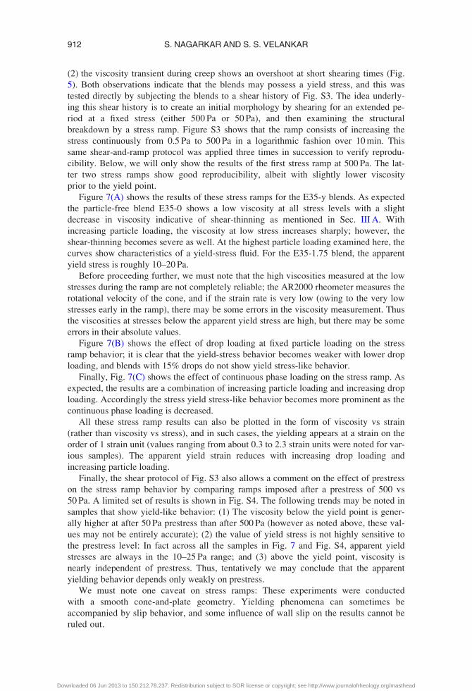
Figure 7(A) shows the results of these stress ramps for the E35-y blends. As expected
the particle-free blend E35-0 shows a low viscosity at all stress levels with a slight
decrease in viscosity indicative of shear-thinning as mentioned in Sec. III A. With
increasing particle loading, the viscosity at low stress increases sharply; however, the
shear-thinning becomes severe as well. At the highest particle loading examined here, the
curves show characteristics of a yield-stress fluid. For the E35-1.75 blend, the apparent
yield stress is roughly 10–20 Pa.
Before proceeding further, we must note that the high viscosities measured at the low
stresses during the ramp are not completely reliable; the AR2000 rheometer measures the
rotational velocity of the cone, and if the strain rate is very low (owing to the very low
stresses early in the ramp), there may be some errors in the viscosity measurement. Thus
the viscosities at stresses below the apparent yield stress are high, but there may be some
errors in their absolute values.
Figure 7(B) shows the effect of drop loading at fixed particle loading on the stress
ramp behavior; it is clear that the yield-stress behavior becomes weaker with lower drop
loading, and blends with 15% drops do not show yield stress-like behavior.
Finally, Fig. 7(C) shows the effect of continuous phase loading on the stress ramp. As
expected, the results are a combination of increasing particle loading and increasing drop
loading. Accordingly the stress yield stress-like behavior becomes more prominent as the
continuous phase loading is decreased.
All these stress ramp results can also be plotted in the form of viscosity vs strain
(rather than viscosity vs stress), and in such cases, the yielding appears at a strain on the
order of 1 strain unit (values ranging from about 0.3 to 2.3 strain units were noted for var-
ious samples). The apparent yield strain reduces with increasing drop loading and
increasing particle loading.
Finally, the shear protocol of Fig. S3 also allows a comment on the effect of prestress
on the stress ramp behavior by comparing ramps imposed after a prestress of 500 vs
50 Pa. A limited set of results is shown in Fig. S4. The following trends may be noted in
samples that show yield-like behavior: (1) The viscosity below the yield point is gener-
ally higher at after 50 Pa prestress than after 500 Pa (however as noted above, these val-
ues may not be entirely accurate); (2) the value of yield stress is not highly sensitive to
the prestress level: In fact across all the samples in Fig. 7 and Fig. S4, apparent yield
stresses are always in the 10–25 Pa range; and (3) above the yield point, viscosity is
nearly independent of prestress. Thus, tentatively we may conclude that the apparent
yielding behavior depends only weakly on prestress.
We must note one caveat on stress ramps: These experiments were conducted
with a smooth cone-and-plate geometry. Yielding phenomena can sometimes be
accompanied by slip behavior, and some influence of wall slip on the results cannot be
ruled out.
912 S. NAGARKAR AND S. S. VELANKAR
Downloaded 06 Jun 2013 to 150.212.78.237. Redistribution subject to SOR license or copyright; see http://www.journalofrheology.org/masthead
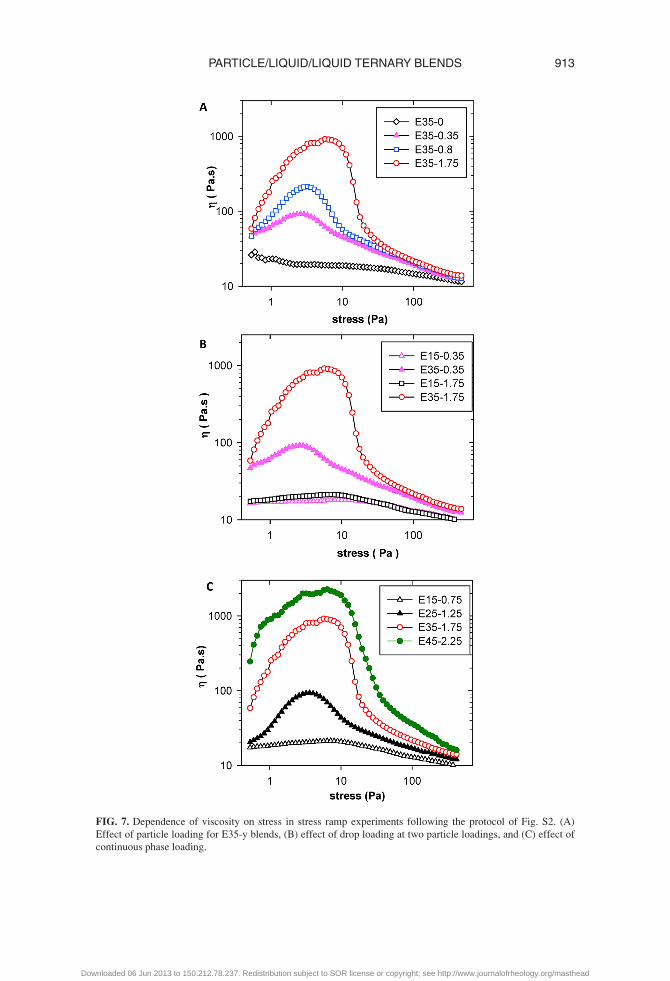
FIG. 7. Dependence of viscosity on stress in stress ramp experiments following the protocol of Fig. S2. (A)
Effect of particle loading for E35-y blends, (B) effect of drop loading at two particle loadings, and (C) effect of
continuous phase loading.
913PARTICLE/LIQUID/LIQUID TERNARY BLENDS
Downloaded 06 Jun 2013 to 150.212.78.237. Redistribution subject to SOR license or copyright; see http://www.journalofrheology.org/masthead

E. Effects of particle wettability: Rheology of blends with DCDMS-modifiedparticles
In Sec. IV, we will interpret the results of the rheology in terms of structural character-
istics of the blends. Specifically, we will comment on the major role played by particle
bridging. As a prelude to that discussion, it is useful to examine the rheology of a blend
in which particles adsorb at the interface but cannot bridge. Previously we had shown
that DCDMS-modified particles adsorb roughly symmetrically at the interface, and there-
fore are incapable of bridging [Nagarkar and Velankar (2012)]. This section briefly
describes the rheology of the corresponding blends. These experiments have only been
performed on the E35-y series of blends (dotted blue trajectory in Fig. 3) with particle
loadings up to 3.5 wt. %.
Figure 8(A) shows that the viscosity of the blends with the DCDMS-modified particles is
significantly lower than of blends with the OTS-modified particles. Once again, the viscosity
behavior is not monotonic with particle addition: The viscosity reduces at low particle load-
ing as compared to the particle-free blend, before rising again at higher particle loading.
Figure 8(B) shows that the blend with DCDMS-modified particles shows a slight vis-
cosity overshoot during creep experiments; however, the magnitude of the overshoot is
substantially smaller than for the blends containing OTS-modified particles.
Finally Fig. 8(C) shows that in the stress ramp experiment, the blends containing
DCDMS-modified particles show modest shear-thinning, but not the extreme yield-like
behavior of the blends containing OTS-modified particles.
IV. DISCUSSION
Before proceeding, we will summarize the chief rheological consequences of adding
interfacially active particles to the blends. It is noteworthy that in all cases, the volume
fraction of particles was low, usually less than 1 vol. %, and the particles do not affect
the bulk rheology of the phases significantly. Thus, all the effects listed below can be
unambiguously attributed to the interfacial activity of the particles. These effects are as
follows:
(1) At very low particle loadings, both particle types can reduce the viscosity of blends,
especially at higher stress levels. At higher particle loadings, the viscosity rises again.
The OTS-particles can induce large increases in viscosity.
(2) Addition of OTS-particles makes the blends highly shear-thinning, and these blends
show apparent yield-like behavior.
(3) During startup of steady flow, OTS-blends show an overshoot in viscosity during
fixed-stress creep experiments.
(4) OTS-particles make the blends more elastic, at least as judged by elastic recoil upon
cessation of shear.
(5) The effects of particles depend severely on wettability; blends containing DCDMS-
modified particles show rheological behavior that is different—even qualitatively—
from blends containing OTS-modified particles.
A. Morphology
We now discuss the microstructural origins of these rheological effects. Figure 9(A)
shows the structure of the PEO drops (after they have been solidified) for the E35-1.75
blend. The drops are obviously nonspherical, and at higher magnification [Fig. 9(B)],
914 S. NAGARKAR AND S. S. VELANKAR
Downloaded 06 Jun 2013 to 150.212.78.237. Redistribution subject to SOR license or copyright; see http://www.journalofrheology.org/masthead

FIG. 8. Effect of particle wettability on rheological properties. (A) Steady shear viscosity at 50 Pa stress, (B)
viscosity transient during steady creep, and (C) viscosity dependence on stress during stress ramp.
915PARTICLE/LIQUID/LIQUID TERNARY BLENDS
Downloaded 06 Jun 2013 to 150.212.78.237. Redistribution subject to SOR license or copyright; see http://www.journalofrheology.org/masthead
many drops are seen to have facets or shallow craters. While images such as Fig. 9(A)
provide an accurate picture of drop sizes and shapes, they do not provide an accurate
description of the morphology quenched from molten conditions. We showed previously
[Nagarkar and Velankar (2012)] that in fact the morphology upon quenching consists of
these same drops heavily clustered together due to particle-bridging. The shallow craters
or facets in Fig. 9(B) correspond to regions that had been bridged. Most of these clusters
are disrupted during selective solvent extraction of PIB, although occasional clusters are
still visible. Even higher magnification at particle-scale resolution [Fig. 9(C)] reveals a
tight packing of particles. Figure 9 refers to the E35-1.75 sample; similar imaging at
much lower particle loading (not shown) reveals that the drops are far larger, sometimes
comparable to the rheometer gap. Furthermore, at low particle loadings, there are not suf-
ficient particles to cover the entire surface: Instead, the particles are preferentially located
in the bridging regions leaving much of the drop surfaces particle-free. Finally, while our
previous research did not discuss the effect of stress, a comparison of Fig. 9(A) (after
50 Pa stress) and Fig. 9(D) (after 500 Pa stress) shows a significant decrease in drop size
as stress increases. Similar SEM images across a much wider range of compositions
[Nagarkar and Velankar (2012)] led to the physical picture of Fig. 1. To summarize, addi-
tion of OTS-modified particles has two morphological consequences. The first is that the
OTS-modified particles can bridge across PEO drops. Bridging occurs at all drop load-
ings and has profound effects on the morphology; most importantly, it glues together the
drops into clusters. The second (not evident from Fig. 9, but shown previously) is an
increase in flow-induced coalescence: Even at particle loadings as low as 0.07 wt. % (the
lowest loading examined), particles were able to greatly increase the drop size.
FIG. 9. SEM images of E35-1.75 with OTS-modified particles. (A)–(C) After shearing at 50 Pa stress for 2000
strain units. (D) After shearing at 500 Pa stress for 2000 strain. The scalebars on the top left of each image are
200 lm in (A) and (D), and 10 lm in (B) and (C). Note that (A) and (D) are nearly the same magnification and
the difference in drop size is readily apparent.
916 S. NAGARKAR AND S. S. VELANKAR
Downloaded 06 Jun 2013 to 150.212.78.237. Redistribution subject to SOR license or copyright; see http://www.journalofrheology.org/masthead

Our previous article did not present structural characteristics of blends containing
DCDMS-modified particles in detail, and we will do so here. Figure 10(A) shows the dis-
persed phase from E35-1.75-DCDMS sample after being subjected to a stress of 50 Pa.
The morphology is altogether different from Fig. 9. First, the size-scale of this structure
is significantly larger than the 300 lm gap at the edge of the cone-plate geometry. It is no
longer clear whether there are discrete drops in the sample; many of the drops appear to
have coalesced together giving the appearance of a bicontinuous structure. The facets or
shallow craters evident in the OTS-blends are not evident. At much higher magnification
[Fig. 10(B)], the particle surface appears to be tightly packed with particles. It must be
emphasized that this sample, which has only �33 vol. % of dispersed phase, is not likely
to be bicontinuous in reality; Fig. 10 is just one portion of the dispersed phase and not
representative of the overall morphology.
It is of interest to examine the dependence of the morphology of the DCDMS blends at
other blend compositions. However, the large size-scale of the morphology in Fig. 10 is
likely to be heavily influenced by the gap size, and indeed under these conditions, the
SEM images are not highly reproducible: In some cases, we see long string-like phases
rather than a morphology that resembles bicontinuity. Therefore, we have conducted addi-
tional experiments examining the effect of particle loading and drop loading, but at a
higher stress level of 500 Pa, at which the size-scale of the morphology is smaller, and
therefore less affected by (although still not altogether independent of) the rheometer gap.
Figure 11 shows the effect of particle loading on E35-y DCDMS-blends quenched af-
ter shearing at 500 Pa. The particle-free blend E35-0-DCDMS [Fig. 11(A)] shows a mor-
phology composed of small spherical drops with the largest drops being much less than
100 lm in diameter. Addition of 0.35 wt. % particles [Fig. 11(B)] greatly increases
the drop size showing that the DCDMS particles strongly promote coalescence. This
was reported in our previous research as well. At this loading, particle-scale images
[Fig. 11(B1)] show particles on the interface, but the coverage is far short of complete.
FIG. 10. E35-1.75 with DCDMS particles after shearing at 50 Pa. (A) Drop-scale structure, and (B) particle-
scale structure at the interface. Scalebar on the top left of each image is 500 lm in (A) and 10 lm in (B). The
lower right image is a magnified view of the top left corner of (B).
917PARTICLE/LIQUID/LIQUID TERNARY BLENDS
Downloaded 06 Jun 2013 to 150.212.78.237. Redistribution subject to SOR license or copyright; see http://www.journalofrheology.org/masthead

FIG. 11. Morphology of E35 blends with DCDMS-modified particles at various particle loadings after shearing
at 500 Pa. (A) is the particle free blend, whereas particle loading increases from (B) to (D). Right column of
images is at higher magnification. Scalebars are 500 lm in the left column and 5 lm in the right column.
918 S. NAGARKAR AND S. S. VELANKAR
Downloaded 06 Jun 2013 to 150.212.78.237. Redistribution subject to SOR license or copyright; see http://www.journalofrheology.org/masthead
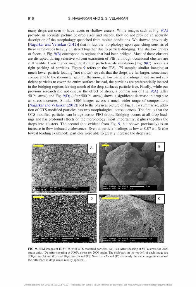
At a higher particle loading [Figs. 11(C) and 11(C1)], a string-like morphology appears,
and the interface appears jammed with particles. To our knowledge, this is the first dem-
onstration of a flow-induced interfacially jammed blend morphology. With an even
higher particle loading [Figs. 11(D) and 11(D1)], the size-scale of the morphology
reduces significantly and the aspect ratio of the drops reduces sharply although they are
still not spherical.
These images suggest the following physical picture (Fig. 12) for the effect of
DCDMS particles on the structure of the blends. At low particle loadings, the particles
greatly promote coalescence. Since the particle loading is too low to cover the interface
completely, drops are spherical. The drop size is chiefly controlled by a steady state bal-
ance between flow-induced breakup and flow-induced coalescence. As particle loading
increases, the surface coverage increases to the point where the drops are forced to take
on a nonspherical shape so that the larger surface area required for accommodating the
particles can be maintained with the same drop volume. We speculate that under these
conditions, the morphology can be either string-like or bicontinuous depending on the
stress level. Finally, at even higher particle loading, the continuing need to accommodate
all the particles on the interface forces a decrease in the size-scale of the dispersed phase.
Finally, we discuss the reasons for the promotion of flow-induced coalescence. As
mentioned in the introduction, we had previously noted instances of particle-induced coa-
lescence in polymer blends [Thareja et al. (2010)], and had speculated that the
“bridging–dewetting” mechanism was involved. Consider two drops colliding when the
upper drop already has a particle adsorbed at the equilibrium contact angle in the region
of the thin film separating the drops [Fig. 13(A)]. During the collision, the particle
bridges across the thin film and adsorbs on both drops simultaneously; at this instant, the
lower contact line is not at the equilibrium contact angle [Figs. 13(B) and 13(D)], and
therefore must recede across the particle. Whether this particle bridge is stable or not
FIG. 12. Schematic of the effect of adding DCDMS-modified particles in polymer blends. (A) is the particle-
free sample, and the particle concentration rises going from (B) to (D). (B) At low particle loadings, the inter-
face is not fully covered and the particles promote coalesence. At higher particle loadings [(C) and (D)], the
interface is jammed and drop size reduces.
919PARTICLE/LIQUID/LIQUID TERNARY BLENDS
Downloaded 06 Jun 2013 to 150.212.78.237. Redistribution subject to SOR license or copyright; see http://www.journalofrheology.org/masthead

depends on how far the contact line recedes, i.e., on the wettability of the particle. If the
particle is preferentially wetted by the drop phase [Fig. 13(B)], the lower contact line
recedes across the particle until the two contact lines meet and coalescence occurs [Fig.
13(C)]. Such particles promote coalescence, and bridging–dewetting is commonly
accepted as the mechanism underlying the antifoaming capability of highly hydrophobic
bubbles [Garrett (1993); Pugh (1996)], or coalescence promotion by particles that are
preferentially wetted by the drop phase [Mizrahi and Barnea (1970); Dickinson (2006)].
If the particles are preferentially wetted by the continuous phase [Fig. 13(D)], the contact
line recedes until the lower interface makes the equilibrium contact angle, and then a sta-
ble bridge is formed [Fig. 13(E)]. In this case, the drops are glued together and coales-
cence can be hindered.
In our previous research [Thareja et al. (2010)], the contact angles of the particles
were unknown and hence bridging–dewetting was proposed as a hypothesis. In the pres-
ent case however, the contact angles of the particles are known from the particle-scale
SEM images (Fig. 2), and hence the bridging–dewetting mechanism may be examined
more critically. The DCDMS-particles are roughly equally wetted by the two phases, and
hence bridging–dewetting can indeed explain the coalescence promotion. In contrast, the
OTS-particles are preferentially wetted by the continuous phase and hence stable bridg-
ing is expected, and indeed bridged clusters were observed at all compositions. Thus in
the case of OTS-particles, bridging–dewetting, at least in the simplistic form of Fig. 13,
cannot readily explain the promotion of coalescence. Indeed, our observations of coales-
cence promotion seem to contradict previous reports that particles wetted by the continu-
ous phase bridge across drops and prevent coalescence [Ashby et al. (2004); Stancik and
Fuller (2004); Horozov and Binks (2006)]. We speculate that in our OTS-particle case,
the accelerated coalescence results from the fact that the region outside the bridged
monolayer is particle-free and hence susceptible to coalescence; accordingly, the pertur-
bations in this region during applied flow are sufficient to rupture the thin film separating
FIG. 13. (A) Collision of two drops with particles adsorbed on the interface. (B) If the particle is preferentially
wetted by the drops, h< 90� is desired. Thus upon initial collision, the contact line recedes across the particle
until the two contact lines meet (C) and coalescence occurs. (D) If the particle is preferentially wetted by the
continuous phase, h> 90� is desired. The contact line recedes until the desired contact angle is reached (E) and
a stable bridge is formed.
920 S. NAGARKAR AND S. S. VELANKAR
Downloaded 06 Jun 2013 to 150.212.78.237. Redistribution subject to SOR license or copyright; see http://www.journalofrheology.org/masthead

the drops. Coalescence is promoted chiefly because bridging offers a means of holding
the drops in close proximity. Thus flow-induced coalescence can be suppressed only at
higher surface coverages when the entire drop surface—even the region outside of the
bridged monolayer—is nearly covered with particles. In contrast, quiescent coalescence
can be suppressed even when the region outside the bridged monolayer is particle-free
[Horozov and Binks (2006)]. This explanation is speculative; other potential explana-
tions, such as a change in the van der Waals attraction between the drops due to particle
adsorption, cannot be ruled out.
B. Rheology
Figures 1 and 12 allow a clear interpretation of the rheology of the ternary blends. We
will focus first on most extreme rheological consequence of addition of particles—the
yield-like behavior. Since the blends with DCDMS-modified particles do not show such
behavior, we may attribute such behavior to the fact that the OTS-modified particles
bridge drops into clusters. While our structural characterization is not able to obtain the
morphology in situ after flow, the fact that a yield stress exists suggests that the clusters
form a percolating network. Indeed similar yield behavior was noted [Lee et al. (2012)]
due to particle bridging in oil/water systems, albeit at far higher particle loadings (8–17
vol. % as compared to �1 vol. % in this paper). In that paper, owing to the higher particle
loading, the morphology appeared similar to a polyhedral foam. We may also draw a
strong analogy to the highly nonlinear viscosity vs stress relationship in wet granular sys-
tems. The most familiar example of this is the yield stress developed by sand by adding a
small amount of water; the water drops form menisci [Fig. 14(B)] that connect together
the particles into percolating clusters, allowing sand castles to be constructed. Similar
yielding behavior has been examined in particle suspensions containing a small amount
of a second fluid that partially wets the particles [Cavalier and Larche (2002); Koos and
Willenbacher (2011)]. Such wet granular systems or suspensions in pendular or capillary
states are also ternary fluid/fluid/particle systems similar to the polymer blends here, but
in a different region of the ternary composition diagram (Fig. 3). Indeed, as illustrated in
Fig. 14, our particle-bridged drops may be considered the exact opposite of menisci-
bridged particles, and it is not surprising to see similar rheological behavior.
In addition to the yield stress, another notable difference between the DCDMS and
the OTS-blends is the overshoot of viscosity during startup of shear. Overshoots
are commonly seen across a wide variety of systems, and previous articles [e.g.,
Groot and Agterof (1994); Whittle and Dickinson (1997); Carrier and Petekidis (2009);
FIG. 14. (A) A particle bridge between two drops. (B) A liquid bridge between two particles. Note that in both
cases, the particles are preferentially wetted by the lighter shaded fluid (blue in electronic version).
921PARTICLE/LIQUID/LIQUID TERNARY BLENDS
Downloaded 06 Jun 2013 to 150.212.78.237. Redistribution subject to SOR license or copyright; see http://www.journalofrheology.org/masthead

Koga et al. (2009)] have cited examples of a variety of systems, e.g., molten polymers,
hard sphere suspensions, fiber suspensions, attractive suspensions, associating polymers,
emulsions, and foams, which show such viscosity behavior, although most of this litera-
ture conducts experiments at a specified rate rather than stress. Such overshoots can often
be attributed to the breakdown of some associated structure prior upon applying flow,
and indeed, the point of maximum viscosity can be regarded as a definition of the yield
point [Moller et al. (2006)]. Our own group has seen viscosity overshoots in polymer
blends with reactive compatibilizer, a system in which optical microscopy showed forma-
tion of large drop clusters [DeLeo and Velankar (2008); DeLeo et al. (2011b)] qualita-
tively similar to those seen here.
Finally, there has been at least one article [Herzig et al. (2007)] showing that particle-
stabilized bicontinuous morphologies (bijels) show a yield stress as well. In that case, the
yield-like behavior cannot be attributed to bridging since the particles are roughly sym-
metrically adsorbed on the interface analogous to the DCDMS-modified particles.
Instead, the yielding behavior was attributed to the fact that the bicontinuous structure
allows the interfacial particles to form a percolating network. Analogously, DCDMS-
blends might also show yield-like behavior if a bicontinuous jammed morphology were
to be realized, e.g., by shearing blends with roughly equal volume fraction of PEO and
PIB. We have not conducted experiments in this region of parameter space.
One last aspect of the rheology worthy of comment concerns the nonmonotonic
behavior of viscosity with particle loading: In Fig. 5, we pointed out that the viscosity of
blends at low particle loadings (e.g., E35-0.35) was lower than of the corresponding
particle-free blend (E35-0), especially at high stress. This is true for the blends containing
DCDMS-particles as well [Fig. 8(A)], and hence cannot be attributed to bridging-induced
clusters. We believe that this unusual behavior is attributable to flow-induced coales-
cence. Specifically, it is well-known that the steady shear viscosity of blends depends on
the orientation of the drops, which in turn depends on capillary number Ca, which is the
ratio of the viscous stress to the Laplace pressure [Frankel and Acrivos (1970); Choi and
Schowalter (1975)]. At small Ca values, the drops remain nearly spherical and the orien-
tation is negligible. With increasing Ca, the drops deform and orient along the flow direc-
tion. These changes in orientation induce shear-thinning as viscosity reduces from its
zero shear value to a lower value that depends on the capillary number. Since a low level
of particle addition was shown to greatly increase the drop size, we suggest that the corre-
spondingly high capillary numbers reduce the viscosity to values below that of the
particle-free blend. As the particle loading increases, the drop size (and hence Ca)
reduces, and the viscosity increases again. Certainly, the more complex effects of par-
ticles—bridging and stabilization of nonspherical drops—would also contribute to the
viscosity increase as particle loading increases.
V. CONCLUSIONS
In summary, we have examined the effect of small (�1 vol. %) of particles to model
polymer blends with a droplet–matrix morphology. We find that the rheological changes
due to particle addition include large increases in the viscosity, highly shear-thinning (or
yield-like) behavior, and overshoots in viscosity during startup of steady shear. We inter-
pret the results in terms of the morphological changes—the bridging and jamming phe-
nomena that occur due to the OTS-particles, and the jamming phenomena due to
DCDMS particles. Both particle types are able to promote flow-induced drop coalescence
at low particle loadings, which is unexpected in light of previous results that bridging
particles stabilize drops against coalescence.
922 S. NAGARKAR AND S. S. VELANKAR
Downloaded 06 Jun 2013 to 150.212.78.237. Redistribution subject to SOR license or copyright; see http://www.journalofrheology.org/masthead
In a qualitative sense, the foremost conclusions of this paper are (1) particles affect
the morphology and rheology of polymer blends even at low volumetric loadings as low
as 0.1 vol. %, and (2) the effects of morphology and rheology depend severely on the
wettability of the particles. These results are likely to apply not just to polymer blends,
but also to small-molecule systems (oil/water) although in that case charge interactions
will likely play a significant role as well. It is remarkable that even though particle/liquid
suspensions and liquid/liquid emulsions have been studied for decades, the rheology of
ternary particle/liquid/liquid systems remains poorly characterized.
ACKNOWLEDGMENTS
This research was funded by NSF-CBET Grant #0932901. The authors are grateful to
Dr. Luling Wang and Professor Sanford Asher for guiding the synthesis of the silica par-
ticles, and to Scott Crawford for assistance with preparing the blends.
References
Almusallam, A. S., R. G. Larson, and M. J. Solomon, “A constitutive model for the prediction of ellipsoidal
droplet shapes and stresses in immiscible blends,” J. Rheol. 44, 1055–1083 (2000).
Asekomhe, S. O., R. Chiang, J. H. Masliyah, and J. A. W. Elliott, “Some observations on the contraction behav-
ior of a water-in-oil drop with attached solids,” Ind. Eng. Chem. Res. 44, 1241–1249 (2005).
Ashby, N. P., B. P. Binks, and V. N. Paunov, “Bridging interaction between a water drop stabilised by solid par-
ticles and a planar oil/water interface,” Chem. Commun. 40, 436–437 (2004).
Binks, B. P., “Particles as surfactants—similarities and differences,” Curr. Opin. Colloid Interface Sci. 7, 21–41
(2002).
Binks, B. P., J. H. Clint, and C. P. Whitby, “Rheological behavior of water-in-oil emulsions stabilized by hydro-
phobic bentonite particles,” Langmuir 21, 5307–5316 (2005).
Bucknall, C. B., and D. R. Paul, “Notched impact behavior of polymer blends: Part 1: New model for particle
size dependence,” Polymer 50, 5539–5548 (2009).
Carrier, V., and G. Petekidis, “Nonlinear rheology of colloidal glasses of soft thermosensitive microgel parti-
cles,” J. Rheol. 53, 245–273 (2009).
Cavalier, K., and F. Larche, “Effects of water on the rheological properties of calcite suspensions in dio-
ctylphthalate,” Colloids Surf., A 197, 173–181 (2002).
Cheng, H. L., Ph.D. thesis, University of Pittsburgh, Pittsburgh, PA, 2009.
Cheng, H. L., and S. S. Velankar, “Interfacial jamming of particle-laden interfaces studied in a spinning drop
tensiometer,” Langmuir 25, 4412–4420 (2009).
Choi, S. J., and W. R. Schowalter, “Rheological properties of non-dilute suspensions of deformable particles,”
Phys. Fluids 18, 420–427 (1975).
DeLeo, C., C. A. Pinotti, M. d. C. Goncalves, and S. Velankar, “Preparation and characterization of clay nano-
composites of plasticized starch and polypropylene polymer blends,” J. Polym. Environ. 19, 689–697
(2011a).
DeLeo, C., K. Walsh, and S. Velankar, “Effect of compatibilizer concentration and weight fraction on model
immiscible blends with interfacial crosslinking,” J. Rheol. 55, 713–731 (2011b).
DeLeo, C. L., and S. S. Velankar, “Morphology and rheology of compatibilized polymer blends: Diblock com-
patibilizers vs crosslinked reactive compatibilizers,” J. Rheol. 52, 1385–1404 (2008).
Dickinson, E., “Interfacial particles in food emulsions and foams,” in Colloidal Particles at Liquid Interfaces,
edited by B. P. Binks and T. S. Horozov (Cambridge University Press, Cambridge, 2006).
Dinsmore, A. D., M. F. Hsu, M. G. Nikolaides, M. Marquez, A. R. Bausch, and D. A. Weitz, “Colloidosomes:
Selectively permeable capsules composed of colloidal particles,” Science 298, 1006–1009 (2002).
Doi, M., and T. Ohta, “Dynamics and rheology of complex interfaces. I.,” J. Chem. Phys. 95, 1242–1248
(1991).
923PARTICLE/LIQUID/LIQUID TERNARY BLENDS
Downloaded 06 Jun 2013 to 150.212.78.237. Redistribution subject to SOR license or copyright; see http://www.journalofrheology.org/masthead

Elias, L., F. Fenouillot, J. C. Majest�e, P. Alcouffe, and P. Cassagnau, “Immiscible polymer blends
stabilized with nano-silica particles: Rheology and effective interfacial tension,” Polymer 49, 4378–4385
(2008).
Fang, Z., C. Harrats, N. Moussaif, and G. Groeninckx, “Location of a nanoclay at the interface in an immiscible
poly(epsilon-caprolactone)/poly(ethylene oxide) blend and its effect on the compatibility of the
components,” J. Appl. Polym. Sci. 106, 3125–3135 (2007).
Fenouillot, F., P. Cassagnau, and J. C. Majeste, “Uneven distribution of nanoparticles in immiscible fluids:
Morphology development in polymer blends,” Polymer 50, 1333–1350 (2009).
Frankel, D. A., and A. Acrivos, “The constitutive equation for a dilute emulsion,” J. Fluid Mech. 44, 65–78
(1970).
Gam, S., A. Corlu, H. J. Chung, K. Ohno, M. J. A. Hore, and R. J. Composto, “A jamming morphology map of
polymer blend nanocomposite films,” Soft Matter 7, 7262–7268 (2011).
Garrett, P. R., “Mode of action of antifoams,” in Defoaming, edited by P. R. Garrett (Marcel Dekker, New
York, 1993).
Gelfer, M. Y., H. H. Song, L. Z. Liu, B. S. Hsiao, B. Chu, M. Rafailovich, M. Y. Si, and V. Zaitsev, “Effects of
organoclays on morphology and thermal and rheological properties of polystyrene and poly(methyl methac-
rylate) blends,” J. Polym. Sci., Part B: Polym. Phys. 41, 44–54 (2003).
Gong, Y., and L. G. Leal, “Role of symmetric grafting copolymer on suppression of drop coalescence,”
J. Rheol. 56, 397–433 (2012).
Grizzuti, N., G. Buonocore, and G. Iorio, “Viscous behavior and mixing rules for an immiscible polymer blend,”
J. Rheol. 44, 149–164 (2000).
Groot, R. D., and W. G. M. Agterof, “Monte-Carlo study of associative polymer networks. 2. Rheologic
aspects,” J. Chem. Phys. 100, 1657–1664 (1994).
Gubbels, F., R. Jerome, P. Teyssie, E. Vanlathem, R. Deltour, A. Calderone, V. Parente, and J. L. Bredas,
“Selective localization of carbon black in immiscible polymer blends: A useful tool to design electrical con-
ductive composites,” Macromolecules 27, 1972–1974 (1994).
Herzig, E. M., K. A. White, A. B. Schofield, W. C. K. Poon, and P. S. Clegg, “Bicontinuous emulsions stabi-
lized solely by colloidal particles,” Nature Mater. 6, 966–971 (2007).
Hong, J., Y. Kim, K. Ahn, S. Lee, and C. Kim, “Interfacial tension reduction in PBT/PE/clay nanocomposite,”
Rheol. Acta 46, 469–478 (2007).
Horozov, T. S., and B. P. Binks, “Particle-stabilized emulsions: A bilayer or a bridging monolayer?,” Angew.
Chem., Int. Ed. Engl. 45, 773–776 (2006).
Hwang, T. Y., Y. Yoo, and J. W. Lee, “Electrical conductivity, phase behavior, and rheology of polypropylene/
polystyrene blends with multi-walled carbon nanotube,” Rheol. Acta 51, 623–636 (2012).
Jansseune, T., P. Moldenaers, and J. Mewis, “Morphology and rheology of concentrated biphasic blends in
steady shear flow,” J. Rheol. 47, 829–845 (2003).
Koga, T., F. Tanaka, I. Kaneda, and F. M. Winnik, “Stress buildup under start-up shear flows in self-assembled
transient networks of telechelic associating polymers,” Langmuir 25, 8626–8638 (2009).
Koos, E., and N. Willenbacher, “Capillary forces in suspension rheology,” Science 331, 897–900 (2011).
Lee, M. N., H. K. Chan, and A. Mohraz, “Characteristics of pickering emulsion gels formed by droplet
bridging,” Langmuir 28, 3085–3091 (2012).
Li, W. J., K. K. Jozsef, and R. Thomann, “Compatibilization effect of TiO2 nanoparticles on the phase structure
of PET/PP/TiO2 nanocomposites,” J. Polym. Sci., Part B: Polym. Phys. 47, 1616–1624 (2009).
Liu, X. Q., Y. Wang, W. Yang, Z. Y. Liu, Y. Luo, B. H. Xie, and M. B. Yang, “Control of morphology and
properties by the selective distribution of nano-silica particles with different surface characteristics in PA6/
ABS blends,” J. Mater. Sci. 47, 4620–4631 (2012).
Madivala, B., S. Vandebril, J. Fransaer, and J. Vermant, “Exploiting particle shape in solid stabilized
emulsions,” Soft Matter 5, 1717–1727 (2009).
Martin, J. D., and S. S. Velankar, “Effects of compatibilizer on immiscible polymer blends near phase inver-
sion,” J. Rheol. 51, 669–692 (2007).
Mizrahi, J., and E. Barnea, “Effects of solid additives on the formation and separation of emulsions,” Br. Chem.
Eng. 15, 497–503 (1970).
924 S. NAGARKAR AND S. S. VELANKAR
Downloaded 06 Jun 2013 to 150.212.78.237. Redistribution subject to SOR license or copyright; see http://www.journalofrheology.org/masthead

Moller, P. C. F., J. Mewis, and D. Bonn, “Yield stress and thixotropy: On the difficulty of measuring yield
stresses in practice,” Soft Matter 2, 274–283 (2006).
Monteux, C., J. Kirkwood, H. Xu, E. Jung, and G. G. Fuller, “Determining the mechanical response of particle-
laden fluid interfaces using surface pressure isotherms and bulk pressure measurements of droplets,” Phys.
Chem. Chem. Phys. 9, 6344–6350 (2007).
Mujumdar, A., A. N. Beris, and A. B. Metzner, “Transient phenomena in thixotropic systems,” J. Non-
Newtonian Fluid Mech. 102, 157–178 (2002).
Nagarkar, S. P., and S. S. Velankar, “Morphology and rheology of ternary fluid/fluid/solid systems,” Soft matter
8, 8464–8477 (2012).
Pawar, A. B., M. Caggioni, R. Ergun, R. W. Hartel, and P. T. Spicer, “Arrested coalescence in Pickering
emulsions,” Soft Matter 7, 7710–7716 (2011).
Phan-Thien, N., and D. C. Pham, “Differential multiphase models for polydispersed suspensions and particulate
solids,” J. Non-Newtonian Fluid Mech. 72, 305–318 (1997).
Pugh, R. J., “Foaming, foam films, antifoaming and defoaming,” Adv. Colloid Interface Sci. 64, 67–142 (1996).
Ray, S. S., and M. Okamoto, “Polymer/layered silicate nanocomposites: A review from preparation to proc-
essing,” Prog. Polym. Sci. 28, 1539–1641 (2003).
Ray, S. S., S. Pouliot, M. Bousmina, and L. A. Utracki, “Role of organically modified layered silicate as an
active interfacial modifier in immiscible polystyrene/polypropylene blends,” Polymer 45, 8403–8413
(2004).
Si, M., T. Araki, H. Ade, A. L. D. Kilcoyne, R. Fisher, J. C. Sokolov, and M. H. Rafailovich, “Compatibilizing
bulk polymer blends by using organoclays,” Macromolecules 39, 4793–4801 (2006).
Soares, B. G., F. Gubbels, R. Jerome, P. Teyssie, E. Vanlathem, and R. Deltour, “Electrical-conductivity in car-
bon black-loaded polystyrene-polyisoprene blends: Selective localization of carbon-black at the interface,”
Polym. Bull. 35, 223–228 (1995).
Stancik, E. J., and G. G. Fuller, “Connect the drops: Using solids as adhesives for liquids,” Langmuir 20,
4805–4808 (2004).
Stratford, K., R. Adhikari, I. Pagonabarraga, J.-C. Desplat, and M. E. Cates, “Colloidal jamming at interfaces: A
route to fluid-bicontinuous gels,” Science 309, 2198–2201 (2005).
Subramaniam, A. B., M. Abkarian, L. Mahadevan, and H. A. Stone, “Non-spherical bubbles,” Nature 438, 930
(2005).
Sumita, M., K. Sakata, S. Asai, K. Miyasaka, and H. Nakagawa, “Dispersion of fillers and the electrical conduc-
tivity of polymer blends filled with carbon black,” Polym. Bull. 25, 265–271 (1991).
Sundararaj, U., and C. W. Macosko, “Drop breakup and coalescence in polymer blends: The effects of concen-
tration and compatibilization,” Macromolecules 28, 2647–2657 (1995).
Tarimala, S., and L. L. Dai, “Structure of microparticles in solid-stabilized emulsions,” Langmuir 20,
3492–3494 (2004).
Thareja, P., K. Moritz, and S. S. Velankar, “Interfacially active particles in droplet/matrix blends of model im-
miscible homopolymers: Particles can increase or decrease drop size,” Rheol. Acta 49, 285–298 (2010).
Thareja, P., and S. Velankar, “Particle-induced bridging in immiscible polymer blends,” Rheol. Acta 46,
405–412 (2006).
Thareja, P., and S. Velankar, “Rheology of immiscible blends with particle-induced drop clusters,” Rheol. Acta
47, 189–200 (2008).
Tong, W., Y. Huang, C. Liu, X. Chen, Q. Yang, and G. Li, “The morphology of immiscible PDMS/PIB blends
filled with silica nanoparticles under shear flow,” Colloid Polym. Sci. 288, 753–760 (2010).
Tucker, C. L., and P. Moldenaers, “Microstructural evolution in polymer blends,” Annu. Rev. Fluid Mech. 34,
177–210 (2002).
Utracki, L. A., and Z. H. Shi, “Development of polymer blend morphology during compounding in a twin-
screw extruder. Part I: Droplet dispersion and coalescence—a review,” Polym. Eng. Sci. 32, 1824–1833
(1992).
Van Hemelrijck, E., P. Van Puyvelde, C. W. Macosko, and P. Moldenaers, “The effect of block copolymer
architecture on the coalescence and interfacial elasticity in compatibilized polymer blends,” J. Rheol. 49,
783–798 (2005).
925PARTICLE/LIQUID/LIQUID TERNARY BLENDS
Downloaded 06 Jun 2013 to 150.212.78.237. Redistribution subject to SOR license or copyright; see http://www.journalofrheology.org/masthead

Van Hemelrijck, E., P. Van Puyvelde, S. Velankar, C. W. Macosko, and P. Moldenaers, “Interfacial elasticity
and coalescence suppression in compatibilized polymer blends,” J. Rheol. 48, 143–158 (2004).
Van Puyvelde, P., S. Velankar, and P. Moldenaers, “Rheology and morphology of compatibilized polymer
blends,” Curr. Opin. Colloid Interface Sci. 6, 457–463 (2001).
Vandebril, S., J. Vermant, and P. Moldenaers, “Efficiently suppressing coalescence in polymer blends using
nanoparticles: Role of interfacial rheology,” Soft Matter 6, 3353–3362 (2010).
Vermant, J., G. Cioccolo, K. Golapan Nair, and P. Moldenaers, “Coalescence suppression in model immiscible
polymer blends by nano-sized colloidal particles,” Rheol. Acta 43, 529–538 (2004).
Vermant, J., S. Vandebril, C. Dewitte, and P. Moldenaers, “Particle-stabilized polymer blends,” Rheol. Acta 47,
835–839 (2008).
Vinckier, I., P. Moldenaers, and J. Mewis, “Elastic recovery of immiscible blends 1. Analysis after steady state
shear flow,” Rheol. Acta 38, 65–72 (1999).
Walker, E. M., D. S. Frost, and L. L. Dai, “Particle self-assembly in oil-in-ionic liquid Pickering emulsions,”
J. Colloid Interface Sci. 363, 307–313 (2011).
Wang, J., and S. Velankar, “Strain recovery of model immiscible blends without compatibilizer,” Rheol. Acta
45, 297–304 (2006a).
Wang, J., and S. Velankar, “Strain recovery of model immiscible blends: Effects of added compatibilizer,”
Rheol. Acta 45, 741–753 (2006b).
Whittle, M., and E. Dickinson, “Stress overshoot in a model particle gel,” J. Chem. Phys. 107, 10191–10200
(1997).
See supplementary material at http://dx.doi.org/10.1122/1.4801757 for information on shear history used in the
experiments, and for additional rheological results on creep recovery and on stress ramps.
926 S. NAGARKAR AND S. S. VELANKAR
Downloaded 06 Jun 2013 to 150.212.78.237. Redistribution subject to SOR license or copyright; see http://www.journalofrheology.org/masthead