rfid-enabled location determination within indoor environments · rfid-enabled location...
TRANSCRIPT

RFID-Enabled Location Determination
Within Indoor Environments
Kevin Curran, Stephen Norrby
School of Computing and Intelligent Systems University of Ulster, Faculty of Engineering, Northern Ireland, UK
Email: [email protected]
Abstract
The ability to track the real-time location and movement of items or people offers a broad range of useful
applications in areas such as safety, security and the supply chain. Current location determination technologies,
however, have limitations that heavily restrict how and where these applications are implemented, including the
cost, accuracy of the location calculation and the inherent properties of the system. The Global Positioning
System (GPS), for example, cannot function indoors and is useful only over large-scaled areas such as an entire
city.
Radio Frequency Identification (RFID) is an automatic identification technology which has seen increasingly
prominent use over the last few decades. The technology uses modulated Radio Frequency signals to transfer
data between its two main components, the reader and the transponder. Its many applications include supply
chain management, asset tracking, security clearance and automatic toll collection. In recent years,
advancements in the technology have allowed the location of transponders to be calculated while interfacing
with the reader. This paper documents an investigation into using an active RFID based solution for tracking.
1 Introduction Accurate location determination systems have been a luxury for large scientific institutions and military installations for some time, but such systems are much too complex and expensive for use in smaller areas such as schools, clinics and even the common household. Similar systems, available commercially, have limitations that make it difficult to accurately determine the location of an object or person in these areas. Many systems that track subjects in real time have severe limitations when tracking individuals in a smaller area, such as a room, building or garden. GPS devices require line of sight with satellites in order to be tracked correctly, meaning devices cannot be tracked indoors or in some areas surrounded by tall buildings. The degree of accuracy to which GPS provides location information is also inadequate for applications that monitor areas with specific boundaries between where an individual is allowed and where they are not. Mobile phone tracking is expensive and works only in more developed areas in range of multiple cell towers. Position estimation, to within an average of fifty metres, is much too inaccurate to track subjects over a small area. Implementing a location determination system using ZigBee received-signal-strength (RSS) has the advantage that the system can work indoors, however the cost of implementation is rather high and the complex network infrastructure may need constant maintenance. Place Lab is an open source solution but since it relies on a centralised list of “landmarks” to work correctly, it would not be suited to smaller areas such as inside buildings (at room level). Hence, a system that could deliver quick and accurate position information (i.e. to within half a metre) at minimal cost could have many extremely useful applications, such as monitoring the safety of children in school, the whereabouts of patients in a hospital or even tracking inmates in a prison. Radio Frequency Identification (RFID) is an automatic identification technology that is widely used across a multitude of applications, including security, safety and asset tracking. A modulated radio frequency signal is used to transfer data from transponders, attached to people, animals or objects, to a reader in the vicinity. Recently, systems have been developed that can calculate the location of a tag, as well as read the data it contains. This major development in RFID technology could allow for the installation of cheap, accurate and reliable location tracking systems to greatly improve safety in schools, clinics and many other areas.

Technologies that determine the current location of a person or object have very useful applications in many areas, including security, safety systems, location-based information services, mapping and the tracking of people, animals and goods. The first highly successful location determination technology was Radio Detection and Ranging, more commonly known as radar. Many engineers and scientists, including Nikola Tesla, had worked on the principles of radar in the early part of the twentieth century. Several systems were patented in the 1930s in the United States, Germany and France. However, the British were the first to use radar as a defence from enemy aircraft attacks, with Robert Watson-Watt’s 1935 patent GB593017. The Second World War brought about a large push in radar research on both the allied and axis sides. Radar systems work by transmitting a very short, high-intensity burst of radio waves at a high frequency. After transmission, the transmitter is disabled and the receiver is turned on. The receiver listens for an echo created by any object (e.g. an aeroplane) within range of the transmitter. The distance of the object from the transmitter can be estimated by measuring the time taken for the echo to arrive. Modern radar systems can also measure the Doppler shift of the echo to estimate the speed of the object. Figure 1 shows the components of a typical radar system.
Figure 1 - A Radar System
This paper outlines the use of RFID-radar technology to track the location of items or people indoors. The RFID based tracking system allows items/people to be tagged with long-range and short-range RFID tags. An RFID-radar system is used to provide 2D position location with identity, range and tracking information, thus keeping the user informed of each person’s location. The user may define areas within the monitored zone as “unsanctioned,” and the system alerts the user if any tracked individual enters any of these unsanctioned areas.
2 Location Determination Technologies There are a number of popular, accessible and versatile technologies available, each with their own advantages and disadvantages for particular applications.
2.1 GPS The Global Positioning System (GPS) is a Global Navigation Satellite System (GNSS), employing a network of twenty-four satellites launched by the United States Department of Defence. Originally intended for military use, it was declared free for civilian use in 1983 by President Ronald Reagan, after Korean Air Lines Flight 007 was shot down by the Soviet Air Force after mistakenly entering Soviet airspace - it was believed that the disaster may have been averted if the flight crew had access to better navigation systems (Pellerin, 2006). GPS satellites circle the Earth twice a day at a very precise orbit. Each satellite contains an atomic clock, and transmits data to the ground at synchronised intervals. The data contains the exact time and the satellite’s position in the form of an ephemeris. GPS receivers also contain a clock and, since the speed of the satellite signal transmission is a known constant, they calculate the distance to each satellite in range by comparing the transmission time sent by the satellite to the reception time given by the receiver’s clock. Once the receiver knows the distance to and position of at least three satellites, it can calculate its position on the ground using a method known as trilateration, similar to triangulation. GPS is used in navigational systems for automobiles, aircraft, ships, spacecraft and even pedestrians, mapping and surveying, geophysics and archaeology, emergency

location, location-based games, mobile satellite communications, weather predication, photographic “Geocoding” and social Networking. Military uses include missile guidance, target tracking, troop movement coordination and reconnaissance.
2.2 Mobile Cellular Systems
Mobile phones, when switched on, send out a signal to cell towers within its vicinity. By comparing the time for the signal to arrive and relative signal strengths from multiple towers, an estimated location of the handset can be obtained. Some mobile phone companies have begun to offer customers location-based services and applications, such as O2’s “Friend Finder” and “Find My Nearest ATM.” 1 Commercial products such as that of LocateMobiles.com are also available, which allow users to register online and track a specific handset on any of the UK’s four major network operators. The location, accurate to within fifty metres, is plotted on a map of the UK and Ireland. A number of limitations are to be noted when considering this approach. Firstly, the accuracy of the location estimation is only to within an average of 50m2, depending on the surrounding landscape and the number of nearby phone masts. This means that this method would be best suited to applications that monitor a wide area, such as a city or county. Another limitation is that mobile phone location queries often work on a subscription or pay-by-query basis. This would not be a cost-effective approach for any application requiring almost real-time updates of a subject’s current location.
2.3 ZigBee ZigBee is based on the IEEE 802.15.4 standard for Wireless Personal Area Networks (WPANs). The ZigBee standard is regulated by the ZigBee Alliance, a group with over 150 members worldwide. ZigBee is similar in concept to other WPANs such as the well-known “Bluetooth,” however it is designed to provide connectivity between small packet devices, while Bluetooth concerns connectivity between large packet user devices such as mobile phones and laptop computers. Thus, ZigBee devices are much less complex than comparable Bluetooth devices and, as such, are a fraction of the cost3. ZigBee is ideal for radio-frequency applications that require secure networking, long battery life and a low data rate. ZigBee WPANs have typical communication speeds of up to 250Kbps, and can support up to 255 devices in a single network. ZigBee is also compatible with most common network topologies, such as mesh networks, star networks and peer-to-peer networks. Common applications for ZigBee include heating, ventilation and air conditioning, lighting systems, intrusion detection, wireless smoke detectors, automatic meter reading and medical monitoring.4 A ZigBee mesh structure can be used to track mobile nodes, effectively giving the real-time location of the carrier of the mobile device. This is achieved with a network of static nodes at fixed points around the tracking area. The position of a mobile node can be triangulated by comparing the received-signal-strengths of at least three static nodes in the vicinity. Accuracy in location estimation is usually to within five metres, due to noise and measurement resolution (Cambridge Consultants, 2006).
2.4 Wi-Fi / Place Lab
Place Lab is a collaborative effort between Intel Research Seattle and other academic institutions which relies on the existing wireless network infrastructure. The Place Lab software uses an online database of the coordinates of known wireless base stations, known as landmarks. Components within the software known as “spotters” retrieve a list of landmarks within the vicinity of the device being used. A second component, known as a “mapper,” attempts to associate the list of landmarks retrieved by the spotters with entries in the database. A final component, called the “tracker,” triangulates the device’s position by using the output from the mapper and the relative signal strengths. Experiments show that the accuracy of the position estimation approaches 20m when the device can detect 4 or 5 distinct beacons in a ten second window. Figure 2 shows a computer with Place Lab software detecting nearby beacons A, B and C. The advantage of Place Lab is that it is free to use and the hardware needed is minimal. Place Lab is also a good choice for users concerned with privacy, as their position is calculated client-side. Place Lab, however, requires quite a number of entries in the database for a user’s location in order to provide accurate position information over a wide area. Some large cities, such as
1 http://www.o2.co.uk/privacy.html 2 http://www.locatemobiles.com 3 http://www.wisegeek.com/what-is-zigbee.htm 4 http://www.zigbee.org/en/about/faq.asp

Seattle, have a large landmark database. It is unlikely, however, to find many landmarks for smaller, less developed areas (McMullan et al., 2007).
2.5 Ubisense
Ubisense is a real-time location system that uses ultra-wideband RF technology to provide positional information accurate to 15cm. The ultra-wideband technology’s advantage over conventional RFID and WiFi is its ability to operate in challenging environments by penetrating walls and other obstacles. The system consists of active tags whose ultra-wideband pulses are used in location calculations, a fixed infrastructure of sensors that receive the pulses from the tags and software to process location data and relay it to users and other related systems. Potential applications include determining the location of a pallet of goods in a warehouse where there may be many obstacles, and allowing the association of data read by a barcode reader with the device’s location at any point in time.
2.6 Ekahau Positioning Engine The Ekahau Positioning Engine (EPE) is a software-based real-time location system, whose patented algorithm uses signal strength calibration to calculate the location of devices with “floor-, room- and door-level accuracy.” EPE is capable of detecting a variety of devices, including Ekahau Wi-Fi Tags, Laptops, PDAs, barcode scanners, passive RFID scanners and other Wi-Fi-enabled devices5. Since EPE is software-based, an existing Wi-Fi infrastructure can be location-enabled with a matter of hours, enabling rapid implementation at an affordable cost. EPE supports all standard 802.11a/b/g access points and a single server can track thousands of assets through multiple buildings. EPE also comes with a Software Development Kit to allow development of custom applications that utilise the EPE system6.
3 Radio Frequency Identification (RFID)
Radio Frequency Identification, is a technology used for the automatic identification and tracking of goods, animals and people. A typical system consists of a three parts – a transponder, a reader, and a controlling application. Transponders hold data on whatever person or object they are attached to, usually containing a unique code used for identification, such as a serial number. When within an appropriate range of a reader, the transponders transmit this data to the reader using radio waves. The reader decodes this radio signal into digital information, which is then relayed to a computer application that makes use of it. RFID technology is extremely widespread, used in many different applications such as security systems, public transport payment systems, the tracking of commercial goods, and livestock identification.
3.1 History of RFID RFID is a relatively old technology, dating back to World War II. Both allied and axis forces had been using Radar technology, which gave an early warning of incoming fighter planes. The problem was that there was no way to identify which of the “dots” on the Radar screen were friendly and which were hostile. German fighters used a crude system where pilots rolled their planes when returning to base. This altered the radio signal reflected back to their base’s Radar system, informing the Radar crew that the incoming planes were friendly7. The British developed the IFF (Identify Friend or Foe) system, which used transponders fitted to allied planes. These transponders broadcasted a signal identifying the aircraft as friendly when “interrogated” by a coded RADAR signal from base. Commercial applications appeared in the 1960s, such as the popular anti-theft system known as Electronic Article Surveillance (EAS). This system used only 1-bit-capacity tags, but provided a cheap and effective countermeasure against theft. RFID development and research increased dramatically into
5 http://www.ekahau.com/?id=4500 6 http://www.ekahau.com/?id=4510 7 http://www.rfidjournal.com/article/view/1338/1/129

the 1970s, with notable developments such as “Short-range radio-telemetry for electronic identification using
modulated backscatter” presented by Alfred Koelle, Steven Depp and Robert Freyman of Los Alamos Scientific Laboratory, Northwestern University. Los Alamos also had teams developing systems for animal tagging and vehicle tracking, in collaboration with other organisations such as the United States Federal Highway Administration. By the late 1980’s, RFID systems were becoming quite widespread in a number of applications such as animal tracking, secure personnel access and toll collection. RFID road toll collection systems were first employed in Europe, such as those in France, Spain, Italy and Norway. The United States followed shortly afterwards with a system developed for the Dallas North Turnpike in 1989. The 1990s saw most toll roads in the United States equipped with RFID. In 1991, the first electronic tolling system that allowed vehicles to pass collection points without the need to slow down was deployed on a highway in Oklahoma. Other notable systems were those of the Kansas turnpike and the Georgia 400, which used multi-protocol readers that were compatible with their own new “Title 21” tags, as well as the older ones of neighbouring systems. Texas Instruments introduced TIRIS (Texas Instruments Registration and Identification System), initially fitted to vehicles as engine immobilisers. The system was modified for a multitude of different applications, including fuel dispensation and the detection of counterfeit casino chips (Landt, 2001). Nowadays, RFID is a part of everyday life. Millions of workers use RFID tags to gain access into company premises, pay tolls on highways, pay parking fees, borrow library books and even play games. Some critics are concerned that RFID tagging will be so ubiquitous in the near future as to be almost Orwellian in nature (Lomas, 2006).
3.2 Components of an RFID System The following is an overview of the major components of an RFID system.
3.2.1 RFID Tag/Transponder The tag, or transponder, is the device attached to a person, animal or object containing information used for identification. The vast majority of tags comprise of an integrated circuit and an antenna. The integrated circuit performs a number of functions, including power control, data storage, data processing, and the modulation and demodulation of radio frequency signals. The data stored usually depends on the protocol used for the communication between the tag and the application receiving data from the reader. A typical tag’s memory could include a unique tag ID, a security password and a Cyclic Redundancy Check (CRC) code, used for error detection. The integrated circuit is connected to an antenna. The shape and size of the antenna is determined by the application of the RFID tag and its designated frequency. Coiled antennas are used in low-frequency and high-frequency “passive tags,” while dipole antennas are employed in Ultra High Frequency tags. The type and design of antenna used is important in balancing the effectiveness and cost of tags. For example, single-dipole antennas are cheaper to produce than dual-dipole antennas, but they rely heavily on their orientation in order to be successfully read by a reader. The integrated circuit and antenna are connected together using a substrate, usually a thin, flexible plastic. An effective substrate is durable and protects the circuit, antenna and their connection from static build-up and physical damage. The substrate and its components are often covered in a type of packaging that offers further protection and allows the tag to be implemented effectively, e.g. casing safe enough for “under-the-skin” implants (Tedjasaputra, 2006). Three different classes of RFID tags exist, describing the source of the tag’s power – passive, active and semi-
passive. Passive tags use no internal power supply, and instead capture the tiny electrical current induced in their antennas by the incoming radio signal (or carrier signal) in a capacitor, a process called inductive coupling. The coiled antenna. The capacitor’s stored energy is then used to power the integrated logic circuits and send a modulated response to the reader. Depending on the operational frequency of the passive tag, two methods of modulation are used. In tags that operate on a frequency less than 100MHz, charge from the capacitor is released to the antenna in varying strengths over time, changing the radio frequency emitted. The reader receives the data by demodulating the signal using these variances. In higher-frequency tags, a method known as backscattering is utilised, in which the resistance of the antenna is modified by the tag, causing an RF signal to be emitted. The reader receives the tag’s data by demodulating the backscatter signal. The operational frequency and antenna design affects the range within which a passive tag

can be read, which can be from 10cm to up to a few metres. Due to their simplistic design, passive tags are inexpensive, long-lasting, and can be so small that they fit inside a sheet of paper8. A contactless smart card is a special type of passive RFID tag where the data is read when it is in close proximity to a reader. The card does not have to be in contact with the reader in order to be read. Its applications include secure access control and loyalty card systems in retail stores. Active tags contain an internal battery that provides a power source for the integrated circuit and antenna. This gives active tags the following advantages over passive tags:
• Autonomy from the reader - Active tags can transmit their own RF signals, rather than have to backscatter one from a reader.
• Increased range – Active tags can typically be read from hundreds of metres away.
• Increased power of signal – The power source boosts the signal, allowing active tags to be read even when underwater or in metal containers.
• Increased storage capacity – More detailed data can be stored about an object, allowing some tags to give information without having to use a serial number to retrieve data from a database.
However, the addition of a power source gives active tags some disadvantages to passive tags:
• More expensive – Active tags cost a lot more to produce because of the increased complexity of the circuit and component design.
• Increased size – The internal power source increases the minimum size of the tag, which may limit possible applications.
• Shorter shelf-life – Active tags need much more maintenance than passive tags, as the internal batteries lose power eventually, meaning that the tag will cease to work until they are replaced. Today, however, batteries in active tags can provide power for up to ten years.
Semi-passive tags are similar to active tags, in that they both contain internal power supplies. They, however, only use it to supply power to the microprocessor and any sensors the tag uses; it is not used to transmit an RF signal. Signals are backscattered to the reader in the same way as a passive tag. Semi-passive tags, while more expensive, generally have faster response times and greater data storage capacity that passive tags due to the battery-assisted circuitry. The battery also usually lasts longer than one contained in an active tag as it is not used to broadcast signals (Weinstein, 2005).
3.2.2 Reader The reader can come in many different forms, such as a in a hand-held portable device (as shown in Figure 2), fixed in a “portal” that reads any tags passing through, or mounted on a conveyor belt, reading tags as they pass by. Readers send out a signal that interrogates any tags in its vicinity. This interrogation can be as simple as a request for all data contained in a tag’s memory, or it can request specific data from different portions of memory. Some readers can also write data to tags that have writeable memory.
Figure 2 - A Hand-Held Portable RFID Reader 9
8 http://news.bbc.co.uk/1/hi/technology/6389581.stm 9 http://www.mobiledataforce.com/Products/pointsyncRFID_Overview.stm

Readers receive a signal back from a tag it has interrogated, demodulates the signal and then decodes it into digital data. This data is then passed onto a computer system for processing. While not precise terms, readers can be classified as either “intelligent” or “dumb.” Intelligent readers are those that can operate on different protocols and filter data they receive. They are usually frequency agile, meaning they can read tags functioning on different frequencies at the same time. A dumb reader can usually only read one type of tag on one frequency using a single protocol. Reader collision is a problem that arises when a signal from one reader interferes with the signal of another, due to overlap. A solution to this problem is Time Division Multiple Access (TDMA), which basically tells the readers to read at different times. However, any system using TDMA has to compensate for duplicate tag reads, as both readers will read the same tag at different times. Another method of combating reader collision is to operate in “dense reader” mode, where a reader switches to a different channel within a frequency range if it detects another reader in close proximity operating on the same channel as its own10.
3.2.3 Software Intelligent readers are often computers in themselves, while more simple readers are networked to a separate computer system. Readers only read data from tags, which would be useless without an application that makes use of it. For example, a reader may pass a serial number of an item onto a database application that retrieves data to display it on a screen, modifies the stock number, sets a “sold” flag as to not trigger a shop’s security system, sets a “loaned” flag for a book in a library, etc. Most reader software will also include functions for the direct control of the reader itself, writing data to tags, error correction and the handling of duplicate tag reads.
3.3 Types of Memory Tags incorporate different types of memory, namely read-only, read-write, and write-once-read-many. Passive tags usually employ read-only memory, which has its data written during the microchip’s manufacturing process. Once written, the data cannot be edited or erased, making the chips very secure and tamperproof. The memory capacity of most passive tags is very small, around twenty bits (or more if needed), so the data stored is usually a unique tag identification number. Write-Once-Read-Many (WORM) memory is similar to read-only, except that the programming is left to the user, rather than done during manufacturing. Once the user has programmed the memory, it can be said to be the same as read-only memory. Most active tags contain read-write memory, which is also user-programmable, but allows much more flexibility as data can be read and rewritten at all times. Read-Write memory means that tags can store a lot more detailed information, which can be changed during each stage of the tracking process of an item. It also allows tags to be reused for different applications later on. Active tags commonly have a memory capacity from 64 bytes to 32Kb, but some hold as much as 1Mb.
3.4 Frequency RFID systems, because they generate and emit electromagnetic waves, are classed as radio systems. Thus, they are subject to regulation from the national radio regulatory body. They must operate on a frequency that does not hinder or disrupt any other radio devices or services, especially television, radio, mobile phones and the radio systems used by the emergency services. There are four main frequency ranges used by RFID systems, illustrated in Table 1:
Frequency Read Range Tag Type Average
Tag Cost
Applications
125KHz – 134KHz (Low Frequency)
1 Foot Passive £0.50 Car Keys, Animal Identification
13.56MHz (High Frequency)
3 Feet Passive £0.25 Smart Cards, Library Systems
10 http://www.rfidjournal.com/faq/19

915MHz – U.S. 868MHz – Europe (UHF)
30 Feet (pass) 300 Feet (act)
Active and Passive £0.25 Commercial Goods Tracking
2.45GHz (Microwave)
100 Feet Active and Passive £12 Motorway tolling systems
Table 1 - Main Frequency Ranges Used for RFID
When choosing what frequency to use, one must consider the environment in which the system is situated, the range at which the tags are to be read and any materials that the RF signals must travel through. Each frequency has its own merits and drawbacks, depending on the application.
• Low-frequency tags are less power hungry and operate very well in environments containing metals, liquids, dirt and mud. Their read-range, however, is very short, often less than one foot (Scher, 2004).
• High-frequency tags have a better read range, ~3 feet, and they work better on metal objects.11
• Ultra-High-Frequency (UHF) tags offer much larger read ranges and data transfer rates than high-frequency and low-frequency tags, but there is a large increase in power consumption and a decrease in penetrative ability through certain materials. Large volumes of UHF tags can be identified at the same time, but tags often require a clear path to the reader to be read correctly (Lahiri, 2006).
• RFID tags using microwave frequencies have faster read-rates than UHF but are much more expensive. Microwaves penetrate non-conductive materials very well, but they are absorbed by water. Signals from microwave tags can usually only be read from a certain direction, depending on where the reader is “pointed” (Scher, 2004).
3.5 Standards Standards in RFID dictate guidelines that must be followed to allow interoperability between different systems. There are standards that deal with the air interface protocol (i.e. the method of communication between tags and readers), data formatting (how data is stored on a tag), and the applications of the RFID systems. Two major organisations involved in creating standards for RFID systems are the International Organisation for Standardisation (ISO) and the Auto-ID Center. The ISO is a worldwide body made up of representatives from national standards organisations. Table 2 shows a list of ISO standards relating to RFID.
Standard Details Notes ISO 11784 Identification of animals Code structure
ISO 11785 Identification of animals Technical concept
ISO 14223 Identification of animals Air interface
ISO/IEC 14443 Proximity ID Cards 1 – Physical Characteristics 2 – Power & Signal Interfaces 3 – Anti-collision & Initialisation 4 – Transmission Protocol
ISO/IEC 15961 RFID for item management Application Interface
ISO/IEC 15962 RFID for item management Data encoding rules & logical memory functions
ISO/IEC 15693 Vicinity ID Cards 1 – Physical Characteristics 2 – Air Interface & Initialisation 3 – Anti-collision & Transmission Control
ISO/IEC 18000 RFID for item management 1 – Foundation for all air interface definitions in ISO/IEC 18000 2 – Air interface communications below 135khz (Type A = 125kHz; Type B = 134.2kHz) 3 – Air interface communications at 13.56MHz 4 – Air interface communications at 2.45GHz 5 – Withdrawn 6 – Air interface communications at 860MHz to 960MHz 7 – Air interface communications at 433MHz
ISO IEC TR 18046 RFID device performance test methods
N/A
ISO/IEC TR 18047 RFID device conformance test methods
3 – Test methods for air interface communications at 13.56MHz 4 – Test methods for air interface communications at 2.45GHz
ISO 18185 Electronic seal tags N/A
11 http://www.rfidjournal.com/faq/17/61

ISO/IEC 19762 Automatic Identification & Data Capture techniques
3 – RFID
ISO 23389 Freight Containers Read-Write RFID
Table 2 - ISO Standards Relating to RFID (RFIDWizards.com, 2007)
3.5.1 The Auto-ID Center The Auto-ID Center is responsible for a number of important standards in RFID. They were set up as a research group at the Massachusetts Institute of Technology in 1999 to develop the Electronic Product Code (EPC) and related technologies for the tracking of products through the global supply chain12. Their objective was to create a cost-effective RFID system that utilised disposable tags, as manufacturers were unlikely to retrieve any tags they put in their products, and operated in the UHF band, to give a suitable read-range for supply chain applications. In order for the RFID system to be used globally - one company could read another company’s tag - the Auto-ID Center developed its own standardised air-interface protocols, namely Class 0 and Class 1.
• The Class 0 standard describes the interface, protocol, operational algorithms, and tag requirements operating at a 900MHz frequency. The tags are read-only and are programmed at the factory.
• The Class 1 standard describes the interface, protocol and tag requirements operating at a frequency of 13.56MHz. The tags are passive and were originally Write-Once-Read-Many (WORM) tags, but most are Read-Many-Write-Many in reality.
0 1 – 0 0 0 0 A 8 9 – 0 0 0 1 6 F – 0 0 0 1 6 9 D C 0
Figure 3 - Example EPC and its Components (Brock, 2001)
In 2003, the Auto-ID Centre split into two separate bodies – Auto-ID Labs, which remained at MIT, and EPCGlobal, which became a subsidiary of the Uniform Code Council (UCC) and Electronic Article Numbering International (EAN). In September of the same year, the Class 0 and Class 1 EPC protocols were handed off to EPCglobal, provided that they would be available to all manufacturers and end-users, royalty-free. The protocols were subsequently ratified by EPCglobal’s Board of Governors. In December 2004, the Class 1 Generation 2 protocol was approved by EPCglobal, which had many advantages over the original Class 1, as well as conforming more to ISO standards.
Field Name Field Size Description
Header 8 bits Identifies the encoding scheme
EPC Manager 28 bits Identifies the manufacturer
Object Class 24 bits Identifies the product class
Serial Number 36 bits Unique ID for the physical product
Table 3 - Data Components in an Electronic Product Code (Myerson, 2007) Generation 2 tags’ advantages over Class 1 tags include improved tag identification, better equipment compatibility, much faster and more reliable tag reading, better tag security with the ability to lock and kill a tag using a reader, better storage capacity and less expensive. While a barcode will identify the manufacturer and class of a product, the Electronic Product Code uniquely identifies each physical product within this class. Figure 3 shows an example of an EPC. Table 3 describes the data components in an Electronic Product Code (Myerson, 2007).
12 http://www.rfidjournal.com/article/articleview/1335/1/129/
Header
8 bits
EPC Manager 28 bits
Object Class 24 bits
Serial Number 36 bits
3.6 Advantages & Limitations of RFID
RFID systems offer many advantages over a broad range of applications. These advantages include:
• RFID tags do not need to be in any physical contact with the reader in order to be read. This speeds up operation and eliminates wear and tear on the tags and the reader.
• Tags can be read in the absence of line of sight of a reader. Readers can also read tags through certain materials that are “RF-lucent” for the frequency being used.
• Tags with read-write capabilities can have their data rewritten many times. This enables tags to be reused and enhances applications with dynamic tag-writing.
• Tags can have read ranges from an inch to more than one hundred feet, allowing applications to use tags that work within an optimal read range
• The storage capacity passive tags can range from a few hundred bits to a few thousand bytes. Active tags can store any amount of data, as its dimensions are not restricted, provided that the tag is deployable.
• Readers can read multiple tags within a very short period of time
• RFID tags can be equipped with other components, such as sensors, to perform other functions
• Many tags are durable enough to survive rough conditions such as heat, humidity and mechanical vibration (Lahiri, 2006).
RFID does suffer from certain limitations and these include:
• Limited penetration of RF signals, even through “RF-lucent” materials;
• Some environments, such as those with RF-opaque and RF-absorbent materials, hinder the technology at certain operational frequencies and, in some cases, prevent it from working at all;
• A bottleneck still exists on the number of tags that can be read within a particular period of time;
• Improper hardware choice and setup can severely hinder an RFID solution. For example, reader collision may occur if multiple readers are not installed correctly;
• Because RFID uses electromagnetic waves, systems can easily be disrupted using jamming devices at the right frequency;
• RFID technology has come into some controversy over privacy. Opponents suggest that RFID, with tags being so small to be barely noticeable, can be used to track individuals without their consent. There are also concerns over the fact that RFID tags attached to products remain functional long after consumer purchase, and can be scanned without their knowledge. Another privacy issue is that if, in future, each retail item is to have its own uniquely-identified tag, every purchased item could be associated with a particular credit card number.
• Even with the cost of some tags being around a few pence each when bought in bulk, RFID is still regarded to be too expensive to implement in many applications, such as item-level stock tracking in retail (Lahiri, 2006).
3.7 Modern applications of RFID The use of RFID technology has become lucrative in many applications. The following sections describe some key applications and the areas in which they benefit from RFID.
3.7.1 Passports A number of countries have issued passports containing RFID tags over the past decade. Most RFID tags contain at least 32kb of EEPROM and, to ensure compatibility with different countries, adhere to the ISO/IEC 14443 proximity card standard, among others. Data stored on the tags may include biometric data in the form of facial recognition, fingerprint recognition and/or iris recognition. Tags may also store travel history, i.e. the time, date and place of entries to and exits from each country, unique chip identification number and digital

signature to protect the stored data from alteration13. This data is used to better authenticate a traveller’s citizenship of a country, and also greatly increases the difficulty in producing a counterfeit passport.
3.7.2 Transportation Charges
Many transportation authorities have introduced RFID proximity cards for cashless payment of fares on buses, trains and subways. Most work by allowing the passenger to use cash to “top up” the card at a machine in the station, giving a certain number of journeys. Examples include the Massachusetts Bay Transportation Authority’s CharlieCard and the Octopus Card in Hong Kong. The latter has since evolved to be used for many applications such as payment at vending machines, supermarkets and car parks. RFID tags are also used on many motorways for toll collection, often without the need for the driver to stop or slow down at all. Such systems include the “Eazy Pass” on the M1 Motorway outside Dublin, Ireland and the DART-Tag on the Dartford Crossing outside London.
3.7.3 Security RFID security systems are employed at many retail stores to alert staff of the attempted theft of an item. Each item contains an RFID tag, either concealed within the packaging or placed in plain sight, acting as a deterrent to shoplifters. RFID readers act as a “gate” that one must walk through to exit the shop. If these readers detect a tag on an item passing through, an alarm is tripped, indicating the attempted theft. To stop legitimately-bought items from tripping the alarm when customers exit the shop, each items tag is deactivated or “killed” at the counter so it will no longer send any information back to the readers. Similar systems are used in libraries, where a book that hasn’t been borrowed at the counter will trip an alarm if it passes through the gates at the exit. However, the tags are not destroyed to allow passage through the gates, as in the retail systems, as the tags need to be reused once the borrower returns the book. Instead, the readers retrieve a unique ID from the tag and consult the library’s database server to conclude whether the alarm needs to be triggered14. Modern cars are equipped with immobilisers that prevent them from being “hotwired” by allowing the engine to start only when the car’s genuine key is being used. Car keys contain RFID tags which store a unique serial number. A reader retrieves this serial number from the car key and compares it to the expected number. If they do not match, the immobiliser is enabled. RFID systems are used by many businesses and organisations to control access to restricted areas, where authorised personnel are given RFID proximity cards. An RFID reader is attached to a system that controls the locking mechanism of a gate or door. The system will only open the lock when a proximity card with a valid ID passes in front of the reader. This type of system allows different levels of security clearance with the same type of card for all personnel.
3.7.4 Supply Chain Much success has been had with the use of RFID systems in the monitoring of goods as they pass through the supply chain. Figure 4 shows a simple diagram depicting the several stages in the supply chain from the manufacturer to the consumer:
Figure 4 - Stages in the Supply Chain
An item can be equipped with an RFID tag to be tracked as it passes through the following points in the chain:
13 http://travel.state.gov/passport/eppt/eppt_2788.html 14 http://www.biblio-tech.com/html/rfid.html
Manufacturer
Retailer
Distributor
Consumer
Transportation
Transportation

1. At the manufacturer’s shipping dock as it is loaded onto a truck; 2. At the receiving dock of the distributor 3. At the distributor’s shipping dock as it is loaded onto a truck; 4. At the retailer’s as the pallet is unloaded; 5. At the sales counter when a consumer buys the product (Lahiri, 2006)
RFID tags offer a number of advantages over barcodes, another popular method for controlling stock in the supply chain:
• They do not require line of sight to be read;
• They can be read at any orientation;
• Multiple tags can be read simultaneously;
• They have a larger read range
• They can store more data, e.g. the time and date it arrives and leaves a certain part of the supply chain;
• Less labour is required as reading is more automated (UPS Supply Chain Solutions, 2005). RFID use is becoming more widespread in the supply chain. Over the past few years, the U.S. retail giant Wal-Mart issued a directive requiring over one hundred of its top suppliers to be compliant with their RFID stock tracking system15. These tags are embedded in pallets and cases to be read in warehouses. Many shipping companies also use RFID tags to track trucks, trailers and shipping containers. Some retailers have considered the potential of using item-level RFID tags in-store. This would allow every item in a trolley to be read at once, calculating the total cost in seconds, whereas a barcode reader would take much longer scanning each item individually.
3.7.5 Healthcare RFID has a number of useful applications in the healthcare and pharmaceutical industries. Pharmaceutical companies can use RFID tags to detect products that are counterfeit, expired or tampered with. They are also useful in clinical trials by improving the tracking of drug usage throughout the testing phase, helping to speed up the approval process by regulatory bodies (UPS Supply Chain Solutions, 2005). Hospitals may make use of RFID tags to keep track of their medical equipment assets, or on their surgical equipment to confirm that each item is fit for use after being properly cleaned and repackaged. Patients can also wear tags (e.g. on wristbands) that contain emergency medical data and also allow them to be tracked throughout the hospital. Some staff may wear RFID tags in order for quick location should an emergency arise (UPS Supply Chain Solutions, 2005). The management of controlled substances and pathogens can be monitored efficiently and safely using an RFID tracking system. RFID tracking can also help to ensure that laboratory specimens, such as blood and biopsy samples, are properly identified (Crounse, 2007).
3.7.6 Animal Tracking and Identification Many farms use RFID systems to track and identify their livestock, where tags are usually attached to the animal’s ear. Each tag contains a unique ID which can then be used to retrieve specific information about the animal from a database, such as the herd it came from, date of birth, inoculations it has had, and blood relations. This becomes especially useful during transportation of the animals, where misidentification of specific animals can have severe financial and health-related consequences. RFID tags are also used to track animal movements, such as the migratory patterns of birds. In 2006, a company named Smart-Tek, based in British Columbia, Canada, successfully completed a test by using RFID to track birds in China, with the objective to map the spread of bird flu (Jones, 2007). A similar system could help prevent the spread of mad cow disease among cattle herds. The state of Colorado in the United States is exploring the possibility of using RFID to track and protect its elk herds (Ou-yang, 2007). Many pet-owners have RFID tags implanted into their pets, which stores the name of the dog, the name of the owner and their contact information. In the event that the pet goes missing, veterinarians or animal rescuers can read the information on the tag using a portable reader.
15 http://www.rfidjournal.com/article/view/642/1/1

3.8 RFID Radar and Location Based Determination
RFID has seen widespread use across many different applications. The vast majority of these applications, however, only use the data contained in tags within the reader’s zone, rather than the location of the tag at any given time. RFID’s potential as a location-determination technology has become increasingly prominent with the development of “RFID-Radar” systems and their installation in places such as prisons, schools and hospitals.
3.8.1 Prisoner Monitoring Several states in America have employed RFID systems to improve security and automate the monitoring of prison inmates. The Los Angeles County Sheriff Department spent $1.5 million U.S. dollars deploying Alanco Technologies’ TSI Prism system at one of their correctional facilities in 2005. The TSI Prism system uses tamper-proof, active RFID tags worn as wristbands by inmates, and RFID readers throughout the jail. Each tag links each inmate to a particular profile in the system, which can be used to restrict them to certain parts of the jail, or keep them away from other particular prisoners. The system alerts prison staff if inmates enter restricted areas or move within a certain range of inmates they are required to stay away from. The ultimate aim is to reduce violence between inmates, deter escape attempts and to monitor their whereabouts at all times16. Alanco’s TSI Prism system has also been deployed in Minnesota, Michigan, Illinois and Ohio, with other states to follow suit17.
3.8.2 Child Safety In 2005, a trial was conducted in Yokohama City, Japan, to monitor the safety and whereabouts of school children as they travelled to and from school. Each participating child wore a 2.4GHz RFID tag complying with the 802.11 Wi-Fi standard. Software known as AeroScout determined the location of the child based on the signal strength of the tag received by Cisco Wi-Fi access points, acting as RFID readers, around the city. The software then used the tag’s unique Media Access Control (MAC) address to record the location in a centralised database. The tags could be read up to one thousand feet away, and location estimation was accurate to within ten metres. Each tag also had a call-button which a child could press if they were distressed or in need of assistance. When pressed, the child’s parents or guardian received an email notification along with an image of a map showing the location of the child. The system could be set up to notify parents or guardians if their child passed a certain Wi-Fi access point18. The Legoland theme park in Denmark introduced the “KidSpotter” system in 2004, where young children are fitted with RFID wristbands when they enter the park. The system tracks these wristbands anywhere within the park’s boundaries, meaning that parents can be alerted of a child’s whereabouts via SMS if their child goes astray.
3.8.3 Alzheimer’s Patients Several tracking systems for patients suffering from Alzheimer’s disease and dementia exist in hospitals and nursing homes around the world. These patients wear wristbands containing RFID tags that are detected by readers all around the premises. If a patient tries to leave without being discharged, or enters a potentially dangerous area, staff members are alerted to their whereabouts and are able to facilitate their safe return. Another similar system is that used by Project Lifesaver, an American non-profit organisation that employs search teams equipped with RFID readers to scan for and locate RFID tags contained in wristbands worn by patients that wander away from home19.
4 RFID Radar Location Determination Prototype
16 http://www.networkworld.com/news/2007/061807-us-state-turns-to-rfid.html 17 http://www.rfidjournal.com/article/view/1601/1/1 18 http://www.rfidjournal.com/article/articleview/2050/1/1/ 19 http://www.projectlifesaver.org/public_html/aboutus.htm

RFID has seen widespread use across many different applications. The vast majority of these applications, however only use the data contained in tags within the reader’s zone, rather than the location of the tag at any given time. Radio Frequency Identification tags can be easily added into most everyday objects. Trolley Scan’s RFID-radar (rfid-radar.com, 2007) is an example of an indoor RFID based location determination system that has the accuracy capability of less than fifty centimetres in an area up to one hundred meters deep, however this depends on the tags used and may be as little as ten meters. The system can track up to fifty tags and locate their location within a few seconds. The system has three main components, the reader, the antenna array and the tags. The reader measures the distance of the signals from the tags, the antenna array for energising the tags and finally the tags themselves. Trolley Scan RFID-radar system claims that it can:
• Monitor a zone of up to 100m deep, to an accuracy of less than half a metre
• All tags in reading zone can be scanned within a matter of seconds
• The reader can map out the location of all transponders in the reading zone in one, two or three dimensions and many readers can work in close proximity with minimal interference due to the bandwidth being only 10kHz at UHF frequencies
The reader connects to the computer via an RS232 port. It measures the distance of signals travelling from transponders and provides an energy field to power them. Two or three receiver channels in the reader allow the angle of the signal’s arrival to be calculated. The reader’s processor can make up to ten thousand range measurements per second and its operational frequency can be set anywhere in the range of 860MHz to 960MHz. The processing module can report the identity, position in 2D or 3D space, and movement at one-second intervals of any tags in the reader zone. Its location accuracy is within half a meter and its pointing accuracy is to within one degree. The tags are passive backscatter Ecotag UHF transponders. The credit-card-sized 200uW EcochipTags have a range of ten meters, while the 5uW stick tags have a maximum operating range of forty meters. The antenna array contains one transmit antenna for energising the passive transponders and one antenna for each receiver, giving a total of three antennas in the array. The system works by measuring the distance the signal travels from each transponder within the reading zone on two receivers. By comparing the ranges on both receivers, the angle of arrival can be calculated, allowing the system to show the range and direction of a tag at the time of reading. By measuring the range many times per seconds, the system can plot the path of moving transponders. Tag location data is streamed to a computer connected to the equipment using an RS-232 port. An example stream, showing data for multiple tags, is shown in Figure 5.
22:45:08 BCBBB0005 21.78 -19.2 - 22:45:08 BCBBB5002 23.53 -0.5 - 22:45:08 BCBBB0026 24.09 31.6 - 22:45:09 BCBBB0004 39.43 -15.5 - 22:45:09 BCBBB0002 11.73 -3.1 - 22:45:09 BBBBB0000 47.88 8.8 - 22:45:09 BCBBB0027 27.01 -22.1 - 22:45:09 BCBBB0026 24.10 32.4 - 22:45:09 BCBBB0002 11.73 -3.0 - 22:45:09 BCBBB0004 39.43 -16.0 - 22:45:09 BCBBB5002 23.53 -2.1 - 22:45:09 BCBBB0005 21.78 -21.5 -
Figure 5: RFID Radar Screen Output
The columns, from left to right in Figure 5, indicate the time of the tag report, the tag ID, the range of the tag in meters and the angle of the tag from the reader’s centre-line. The ‘P’ at the end indicates that the radar has temporarily lost contact with the tag since the last report cycle. Figure 6 shows a graphical representation of the location of the tags in the above data stream, in the demo program supplied with the unit.

Figure 6 - Trolley Scan RFID-Radar Software GUI We evaluated the base performance of the RFID-radar by comparing the estimated location with the true location of tags in an indoor scenario. Tag Reading range however is affected by goods placed in the path between antenna and tag. The RFID-radar comes with two types of speed tags. The single speed tag they claim can work at up to 51 Kmh and the dual speed tag works at up to 12 Kmh. The RFID reader utilizes an array of adjacent antennas. One transmits an RF constant field to energize the passive transponders, while others depending on the spatial tracking, receive RF signals from transponders. A receiving antenna determines a tag location in one dimension, and two are needed for 2D with three for 3D. RFID-radar has two receiving antennas and it determines location in 2D. Dipoles couple to radiation polarized along their axes, so the visibility of a tag with a simple dipole-like antenna is orientation-dependent. Tags with two orthogonal or nearly-orthogonal antennas, often known as dual-dipole tags, are much less dependent on orientation and polarization of the reader antenna, but are larger and more expensive than single-dipole tags. We tested just single-dipole tags, so the measurements were strictly dependent on their polarization. The antenna was horizontal to the ground and also the tags had to be horizontal to the ground. As the manual refers, when one of the antennas has the wrong polarisation, especially the energiser antenna and the transponder, then no energy is transferred to the transponder and as a result it does not work. The RFID-radar includes three patch antennas in total, which are used to provide a service in close proximity to metal surfaces, but the structure is 2 cm thick, and the need to provide a ground layer and ground connection increases the cost relative to simpler single-layer structures. The radio frequency environment is a hostile environment for signal strength-based location systems. This is because signal propagation is characterised by reflections, diffractions, and scattering of radio waves caused by structures within the building. Multipath (distortion of a signal due to many different paths to get to the receiver) is an enemy of narrow-band radio. It causes fading where wave interference is destructive. Some UWB systems use "rake" receiver techniques to recover multipath generated copies of the original pulse to improve performance on receiver. Other UWB systems use channel equalization techniques to achieve the same purpose. Narrow band receivers as in RFID-radar can use similar techniques, but are limited due to the poorer resolution capabilities of the narrow band systems. Multipath within buildings is strongly influenced by the layout of the building, the construction material used, and the number of people in the building. As the number of people in the building varies, the propagation characteristics of RF signals change as well. This is because the human body is made up of water and water absorbs RF signals. At different times of the day, a different number of humans may be present in the building causing the signal strength at the various locations in the building to vary considerably. As a consequence, a Radio Map created at any one particular time may not accurately reflect the environment at a different time. This can reduce the accuracy of the RADAR system considerably.
For this reason an appropriate indoor test scenario was chosen to test the systems accuracy and we also verified the performance of the system through the following characteristics. With regards to the actual location estimates, we looked for sufficient precision so that the reported position should be within the range accuracy stated by the maker and systems operation should not interfere with other systems nor crash in active environments. With regard to tracking performance the tracking system should not make jumps that the tracked object would never perform and the trace of the target on screen (or in database) should resemble the actual motion of the target. Additionally, the tracking should show a delay that remains steady and systems operation should not be limited to just a handful of moving nodes and should allow additional nodes to migrate in and fade out. To respect all these constraints, the experiments were carried out in the first floor of MG building in the Magee Campus of the University of Ulster, in a room without humans but containing office furniture (desks,

chairs, bookcases and similar). All experiments for the RFID radar were carried out in the same lab as the system could not penetrate walls. Dots on the map in Figure 7 are the calibrated locations.
(2,1)
(0,0)
(2,0)
(0,1) (0,2) (0,3) (0,4) (0,5)
(1,0) (1,3)
(2,2) (2,3)
(1,5) (1,4) (1,1)
(2,4)
(1,2)
(4,0)
(3,0) (3,1)
(4,2) (4,1)
(3,3) (3,2)
(2,5)
(3,4)
(4,4) (4,5)
(3,5)
(4,3)
RADAR
ANTENNA
READER Obstacle1
Obstacle2
Obs tacle3 Obstacle4
Obs tacle5
Figure 7: Room MG281 with all calibrated locations
One design consideration for the evaluation was how the system would translate positional data from the RFID-Radar system to a graphical representation shown on our prototype map. The system was “calibrated” for the area to be monitored, by placing a transponder at the far edge of the area and storing its range information. This “total range,” shown in Figure 8 was then used in calculations to depict the relative position of transponders to the equipment on the on-screen map. Figure 8 shows the layout of a simple room to be monitored using the RFID-Radar system. A transponder is placed on the far wall, giving the relative location data of the “far edge” of the monitored area. The location data is stored in the program and is assigned to the corresponding edge of the map in the GUI. The transponder used in the calibration process is no longer needed and can be reassigned to an individual to be tracked by the system.
Total Range / Centre Line
Monitored Area
Transponder
Angle
Range Reading
John Smith
On-Screen Map
Real-World
Tracker
RFID Radar Antenna
Original
Transponder
position for
calibration
Figure 8: Tracking a Transponder after Calibration
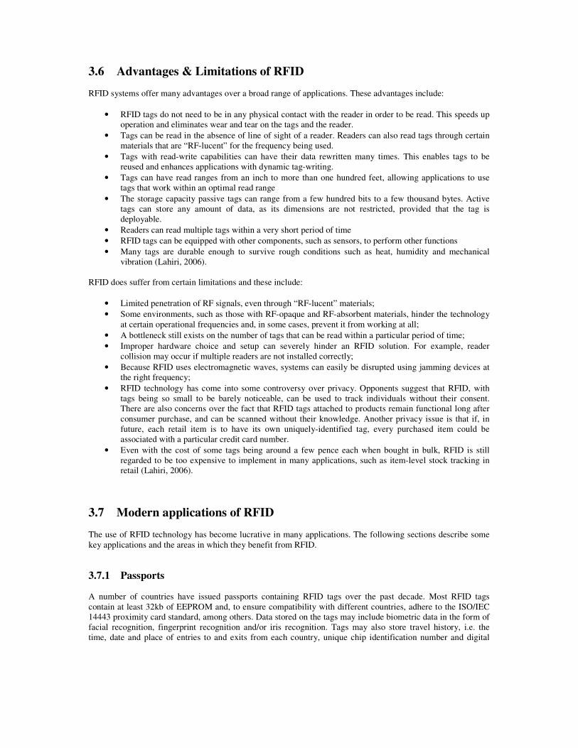
Figure 9 shows how we translated location data from a transponder onto the map in the GUI. It can be seen that a transponder’s range and angle reading, together with the centre line, creates an imaginary right-angled
triangle. With trigonometric calculations, and the known total range, the triangle could be scaled down so that the icon depicting the tag will appear on the map in the location corresponding to the real tag’s location.
6m (Range of Tag)
15°
.
Person with Tag
On-Screen Map
Antenna
Radar System Tag Tracked On Screen
Centre-Line
Figure 9: Overview of System
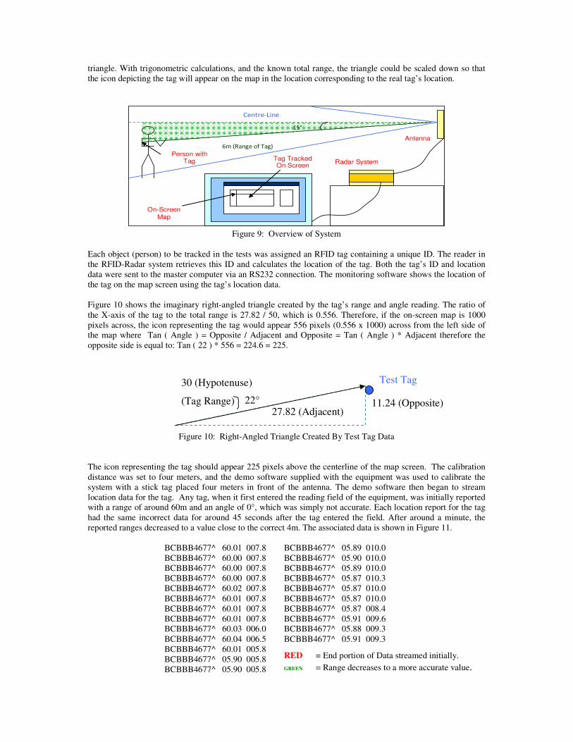
Each object (person) to be tracked in the tests was assigned an RFID tag containing a unique ID. The reader in the RFID-Radar system retrieves this ID and calculates the location of the tag. Both the tag’s ID and location data were sent to the master computer via an RS232 connection. The monitoring software shows the location of the tag on the map screen using the tag’s location data. Figure 10 shows the imaginary right-angled triangle created by the tag’s range and angle reading. The ratio of the X-axis of the tag to the total range is 27.82 / 50, which is 0.556. Therefore, if the on-screen map is 1000 pixels across, the icon representing the tag would appear 556 pixels (0.556 x 1000) across from the left side of the map where Tan ( Angle ) = Opposite / Adjacent and Opposite = Tan ( Angle ) * Adjacent therefore the opposite side is equal to: Tan ( 22 ) * 556 = 224.6 = 225.
Figure 10: Right-Angled Triangle Created By Test Tag Data The icon representing the tag should appear 225 pixels above the centerline of the map screen. The calibration distance was set to four meters, and the demo software supplied with the equipment was used to calibrate the system with a stick tag placed four meters in front of the antenna. The demo software then began to stream location data for the tag. Any tag, when it first entered the reading field of the equipment, was initially reported with a range of around 60m and an angle of 0°, which was simply not accurate. Each location report for the tag had the same incorrect data for around 45 seconds after the tag entered the field. After around a minute, the reported ranges decreased to a value close to the correct 4m. The associated data is shown in Figure 11.
BCBBB4677^ 60.01 007.8 BCBBB4677^ 60.00 007.8 BCBBB4677^ 60.00 007.8 BCBBB4677^ 60.00 007.8 BCBBB4677^ 60.02 007.8 BCBBB4677^ 60.01 007.8 BCBBB4677^ 60.01 007.8 BCBBB4677^ 60.01 007.8 BCBBB4677^ 60.03 006.0 BCBBB4677^ 60.04 006.5 BCBBB4677^ 60.01 005.8 BCBBB4677^ 05.90 005.8 BCBBB4677^ 05.90 005.8
BCBBB4677^ 05.89 010.0 BCBBB4677^ 05.90 010.0 BCBBB4677^ 05.89 010.0 BCBBB4677^ 05.87 010.3 BCBBB4677^ 05.87 010.0 BCBBB4677^ 05.87 010.0 BCBBB4677^ 05.87 008.4 BCBBB4677^ 05.91 009.6 BCBBB4677^ 05.88 009.3 BCBBB4677^ 05.91 009.3
27.82 (Adjacent) 11.24 (Opposite)
30 (Hypotenuse)
(Tag Range) 22°
Test Tag
RED = End portion of Data streamed initially.
GREEN = Range decreases to a more accurate value.

Figure 11: Associated data from radar
The angle reports were sometimes erratic, with values fluctuating in a range of 0° - 6°. This was not a major problem at the small test range of 4m as a change of angle that small would not make a very noticeable difference in its mapped location. However, at large ranges, e.g. 30m, even a small fluctuation in the angle value could significantly affect its position on the map. Once the tag’s range reports settled on a value near 4m, moving the tag further from or closer to the antenna did not increase or decrease the range. Once the tag was moved, the “RANGE” command had to be submitted to the equipment to recalculate the new range, which took an average of 30 seconds. Sometimes the newly-calculated range was inaccurate, e.g. increasing from 4m to 9m when moving the tag closer to the antenna. The main problem unearthed was that the reader was not able to report a correct range or a Tag ID for those locations which were not in line of sight (LoS) with the antennas. LoS is a requirement too restrictive since in a typical indoor environment there are lots of obstacles between the tags and the Antennas. In the room there are some metal obstacles drawn in grey in Figure 12. For static measurements (i.e. objects were not moving), the average error distance of RFID-radar was found to be 4.19m.
( 2 ,1 )
( 0 ,0 )
( 2 ,0 )
( 0 ,1 ) ( 0 ,2 ) ( 0 ,3 ) ( 0 ,4 ) ( 0 ,5 )
(1 ,0 ) ( 1 ,3 )
( 2 ,2 ) ( 2 ,3 )
( 1 ,5 ) ( 1 ,4 ) ( 1 ,1 )
( 2 ,4 )
( 1 ,2 )
( 4 ,0 )
( 3 ,0 ) ( 3 ,1 )
( 4 ,2 ) ( 4 ,1 )
( 3 ,3 ) ( 3 ,2 )
( 2 ,5 )
( 3 ,4 )
( 4 ,4 ) ( 4 ,5 )
( 3 ,5 )
( 4 ,3 )
A N TE N N A
R E A D ER O bst acl e1
O bsta cl e2
O bst acl e3 O bst acl e4
O bsta cl e5
Figure 12: Locations where RFID-radar failed to locate tags in red (Good spots are in bold green)
Problems for the failure of the reader reporting the range came from Obstacle1 and Obstacle2 (the first one is Lab furniture and the second one a structural vertical building column). Of course in a normal office, there will often be obstacles (objects sizeable compared to the wavelength of the operating frequency, from a couple of centimetres upwards) made of wood or metal. Figure 12 shows the locations in red where the radar failed to log the tag. The bold lines in green highlight locations (2,0), (2,1), (2,2), (2,4) and (2,5) where the Radar had good measurements from the tags. Table 4 shows a sample of locations and measurements.
Location Tag ID Range
(m)
Angle
(grad)
Real
Range(m)
AvgRange
accuracy(m)
(0,2) BCBBB4691 12.09 17.63 18.11 24.19 18.84
0.0 0.0 0.0 0.0 0.0
13.82 (18.17) 4.35
(0,3) BCBBB4677 11.88 18.44 15.00 15.34 9.12
0.0 0.0 0.0 0.0 0.0
11.17 (13.95) 2.78
(0,4) BCBBB4685 12.91 20.67
-16.9 -16.9
9.70 (14.25) 4.55

14.47 12.23 10.97
-13.8 -16.9 -14.8
(4,5) BCBBB4684 10.75 10.74 13.33 13.36 13.15
-10.1 -11.8 -10.0 -9.8 -10.9
6.47 (12.26) 5.79
Table 4: Locations with poor measurements Finally, we tested the ability to track relatively fast moving objects. When the distance of the Tags to the antenna is small, the Accuracy should be high, however when the read range starts increasing uncertainty is introduced into the system. Here we used the single speed Claymore tag. The path navigated for tests shown in Figure 13 was traversed at a very slow walking pace. The average length of each walk was 2 minutes and the sampling rate was 30s. Obstacles caused the reader to lose the tag thus the accuracy of measurements was poor. We found the radar to require~10-20s to determine the exact position of tags. We found this seriously limiting and would only recommend for static situations where transponders are relatively stationary. However, in reality devices to be tracked are not fixed to a location21. Here we found the average error distance for slowly moving devices was 10m.
Figure 13: Room MG281 with the test navigation path
We noticed an initial delay in reporting a tag’s location. These observations may be an indicator that the accuracy of the RFID-Radar equipment is adversely affected in smaller environments where obstacles and interference from other technology may hinder measurement. Range and angle readings often failed to be updated correctly when the tag was moved around. Furthermore, because of frequent fluctuations in the range and angle data supplied by the RFID-Radar equipment, the icons on the map, representing the real-world tags, appeared to “jump” around the point on the map, even if the tag itself was stationary, especially at large ranges.
5 Conclusion We found the equipment yielded too many inaccurate readings to use the prototype in any practical way. Trolley Scan’s RFID-radar transponders were relatively cheap however and the reader can map out the location of all transponders in the reading zone in one, two or three dimensions. Drawbacks were that signals from transponders can be interfered with or may not be read correctly through certain “RF-lucent” materials. For instance, while the claimed reading range of the reader is one hundred meters, the actual range with 5uW passive stick-type transponders is around forty meters. The number of transponders in the reading zone is limited to fifty and only the current range of Ecotag transponders is supported. Finally tags are accurately tracked only when moving under a certain speed and it has to be stated that there is not a strong user-base or development community

Even with accurate tag location data, there is a delay of nearly a minute when calculating the location of a new tag that has entered the radar’s field of view, and a similar delay when updating tag data when the tag has moved. These delays would mean that RFID-Radar would be impractical for applications that require accurate real-time locations of moving objects or people over large areas. The RFID-Radar equipment would function best in a large, open environment, with few obstacles and no interference from other RF devices. Suitable applications may include locating stock in an open-plan warehouse, or the location of a parked car in a car park. Delays in updating tag positions would not be critical in these situations, as the tags would most likely be stationary when using the system. RFID technology used in location determination systems may become much more widespread in the future, with new developments such as Ultra-Wideband tags that significantly improve performance and efficiency in indoor environments
6 References Brock, D. L. (2001), The Electronic Product Code (EPC) – Available at : http://interval.hu-berlin.de/downloads/rfid/EPC/MIT-AUTOID-WH-002.pdf
Cambridge Consultants (2006), Zonal Location and Asset Tracking with ZigBee Technology (using RSSI) – Available at : http://www.zigbee.org/imwp/idms/popups/pop_download.asp?contentID=9567
Crounse, Dr. B. (2007), RFID: Increasing patient safety, reducing healthcare costs – Available at : http://www.microsoft.com/industry/healthcare/providers/businessvalue/housecalls/rfid.mspx Jones, K. (2006), Using RFID tags to track bird flu, EE Times (TechWeb) – Online at : http://www.eetimes.com/news/latest/showArticle.jhtml;jsessionid=1K5RGLBMKOARWQSNDBECKHSCJUMEKJVN?articleID=183702439 Lahiri, S. (2005), RFID Sourcebook, IBM Press, ISBN 0131851373 Landt, Dr. J. (2001), Shrouds of Time – The History of RFID – Available at: http://www.transcore.com/pdf/AIM%20shrouds_of_time.pdf Lomas, N. (2006) How Orwellian Can You Get – RFID For Air Travellers – Available at : http://networks.silicon.com/lans/0,39024663,39163311,00.htm McMullan C., Cahill D., Fry D. (2007) Place Lab Geopositioning System - Available at : http://ntrg.cs.tcd.ie/undergrad/4ba2.05/group1/index.html
Myerson, J. (2006), RFID In the Supply Chain, CRC Press, ISBN 0849330181
Ou-yang J. (2007), RFID Will Revolutionize the World - Available at : http://www.cse.ohio-state.edu/~ouyang/RFID%20Technology.htm
Pellerin, C. (2006), United States Updates Global Positioning System Technology - Available at : http://usinfo.state.gov/xarchives/display.html?p=washfile-english&y=2006&m=February&x=20060203125928lcnirellep0.5061609
RFID-Radar.com (2007) – Available at : http://www.rfid-radar.com
RFIDWizards.com (2007), ISO RFID Standards: A Complete List – Available at : http://www.rfidwizards.com/index.php?option=com_content&task=view&id=242&Itemid=174
RSA Laboratories (2007), RFID, A Vision of the Future – Available at : http://www.rsa.com/rsalabs/node.asp?id=2117
Scher, B. (2004), Understanding RFID Frequencies – Available at : http://www.rfidusa.com/superstore/pdf/Understanding_RFID_Frequencies.pdf
Stockman, H. (1948), “Communications by Means of Reflected Power”, Proceedings of the IRE, pp1196-1204
Tedjasaputra, A. (2006) RFID Tag Attachments – Available at : http://www.rfid-asia.info/2006/12/rfid-tag-attachments.htm
UPS Supply Chain Solutions, RFID In Healthcare, 2005 – Available at : http://www.ups-scs.com/solutions/white_papers/wp_RFID_in_healthcare.pdf Weinstein, R. (2005), RFID: A Technical Overview and its Application to the Enterprise - Available at : http://ieeexplore.ieee.org/iel5/6294/32043/01490473.pdf?tp=&arnumber=1490473&isnumber=32043 Wideman, R. Max, Project Life Spans in the 1990s, 2004 – Available at : http://www.maxwideman.com/papers/plc-models/1990s.