rf safety overview for installation/services personnel - rf safety...alcatel-lucent – wireless...
TRANSCRIPT
RF Safety Overview for Installation/Services Personnel
Rooftop Wireless Base Stations
Paul A. TestagrossaAlcatel-Lucent – Wireless CTOInternational Telecommunication Safety Conference
Denver, CO Sept 14 – 16, 2010

Content
1. Introduction – Background & historical activity in wireless area
2. FCC RF Guidelines
3. Typical wireless base station configurationsTowersRooftopsAntennas
4. Antenna compliance boundary (exclusion zone)
5. Rooftop RF environmentMeasurement dataRF Personal Monitors
6. RF Signage
7. Conclusions

Copyright © 2010 Alcatel-Lucent. All rights reserved.3 | International Telecommunication Safety Conference| Sept 2010
Introduction – Background & historical activity in wireless area

Copyright © 2010 Alcatel-Lucent. All rights reserved.4 | International Telecommunication Safety Conference| Sept 2010
Background & historical activity in wireless area
Historically, Bell Labs philosophy has been to be proactive in ensuring the safety and compliance of our wireless telecommunication products and systems, including:
Satellite communications (satcom)
Point-to-point microwave radio (terrestrial radio)
Personal wireless communications (cellular)Leading roles in safety standard development for human exposure to electromagnetic energy
IEEE Int’l Committee on Electromagnetic Safety (ICES)
IEC TC106

Copyright © 2010 Alcatel-Lucent. All rights reserved.5 | International Telecommunication Safety Conference| Sept 2010
Background & historical activity in wireless area
C95.1-2005 “IEEE Standard for Safety Levels with Respect to Human Exposure to Radio Frequency Electromagnetic Fields, 3 kHz to 300 GHz
C95.2-1999: “IEEE Standard for Radio-Frequency Energy and Current Flow Symbols" (Reaffirmed in 2005)
C95.3-2002: "IEEE Recommended Practice for Measurements & Computations of Radio Frequency Electromagnetic Fields with Respect to Human Exposure to such Fields, 100 kHz to 300 GHz“
C95.4-2002: "IEEE Recommended Practice for Determining Safe Distances from Radio Frequency Transmitting Antennas when Using Electric Blasting Caps“
C95.6-2002 “IEEE Standard for Safety Levels with Respect to Human Exposure to Electromagnetic Fields, 0—3 kHz
C95.7 -2005: "IEEE Recommended Practice for Radio Frequency Safety Programs.“
http://www.ices-emfsafety.org/

Copyright © 2010 Alcatel-Lucent. All rights reserved.6 | International Telecommunication Safety Conference| Sept 2010
FCC RF Safety Guidelines
Copyright © 2010 Alcatel-Lucent. All rights reserved.7 | International Telecommunication Safety Conference| Sept 2010
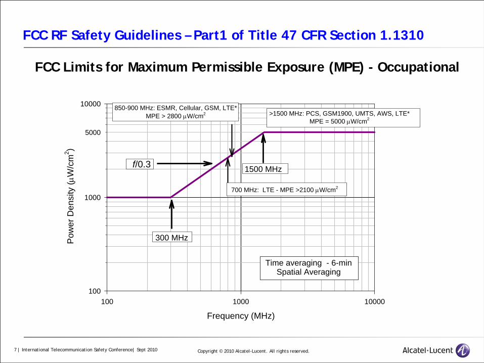
FCC RF Safety Guidelines – Part1 of Title 47 CFR Section 1.1310
FCC Limits for Maximum Permissible Exposure (MPE) - Occupational
Frequency (MHz)
100 1000 10000
Pow
er D
ensi
ty (μ
W/c
m2 )
100
1000
10000 850-900 MHz: ESMR, Cellular, GSM, LTE*MPE > 2800 μW/cm2 >1500 MHz: PCS, GSM1900, UMTS, AWS, LTE*
MPE = 5000 μW/cm2
700 MHz: LTE - MPE >2100 μW/cm2
5000
300 MHz
f/0.3 1500 MHz
Time averaging - 6-minSpatial Averaging

Copyright © 2010 Alcatel-Lucent. All rights reserved.8 | International Telecommunication Safety Conference| Sept 2010
FCC RF Safety Guidelines
Copyright © 2010 Alcatel-Lucent. All rights reserved.9 | International Telecommunication Safety Conference| Sept 2010
FCC RF Safety Guidelines - OET Bulletin 65

Copyright © 2010 Alcatel-Lucent. All rights reserved.10 | International Telecommunication Safety Conference| Sept 2010
FCC RF Safety Guidelines - Telecom Act of 1996
The Telecommunications Act of 1996 is the applicable Federal law with respect to consideration of environmental effects of RF emissions in the siting of wireless facilities. With respect to personal communication services, e.g., cellular, PCS, Section 704 of the Telecommunications Act of 1996 states the following:
"No State or local government or instrumentality thereof may regulate the placement, construction, and modification of personal wireless service facilities on the basis of the environmental effects of radio frequency emissions to the extent that such facilities comply with the Commission's regulations concerning such emissions."

Copyright © 2010 Alcatel-Lucent. All rights reserved.11 | International Telecommunication Safety Conference| Sept 2010
Typical wireless base-station configurations

Copyright © 2010 Alcatel-Lucent. All rights reserved.12 | International Telecommunication Safety Conference| Sept 2010
Wireless base-station configurations - Towers
Antennas
Equipment huts

Copyright © 2010 Alcatel-Lucent. All rights reserved.13 | International Telecommunication Safety Conference| Sept 2010
Wireless base-station configurations – Rooftop
Antennas
outdoor equipment cabinets – equipment huts

Copyright © 2010 Alcatel-Lucent. All rights reserved.14 | International Telecommunication Safety Conference| Sept 2010
Wireless base-station configurations – Antennas
Omni-directional base-stationOmni-directional antenna (whip)
Isotropic antenna pattern
Sectorized base-stationdirectional antenna (panel)beam-type antenna pattern
Front plane (aperture)
Back plane

Copyright © 2010 Alcatel-Lucent. All rights reserved.15 | International Telecommunication Safety Conference| Sept 2010
Wireless base-station configurations – Antennas
ISOTROPIC emission pattern Directional-type emission pattern
Copyright © 2010 Alcatel-Lucent. All rights reserved.16 | International Telecommunication Safety Conference| Sept 2010
Antenna compliance boundary(standoff distance, exclusion zone)

Copyright © 2010 Alcatel-Lucent. All rights reserved.17 | International Telecommunication Safety Conference| Sept 2010
Antenna compliance boundary – directional antenna
Dup
Dfront
Ddown
Dback
Dside
Dside
General Public boundary
Occupational boundary
DsideDside
Dfront
Occupationalboundary
GeneralPublic boundary Antenna
AntennaDback
Specifications:Freq = 869 MHzAntenna length = 6 ftHBW = 650
Input power = 100 W
Occupational Compliance Boundary (Dfront) = 5.5 ft
General Public Compliance Boundary (Dfront) = 27.5 ft
zone around antenna beyond which the safety guidelines for worker or the general public are not exceeded

Copyright © 2010 Alcatel-Lucent. All rights reserved.18 | International Telecommunication Safety Conference| Sept 2010
Antenna compliance boundary – directional antenna
ADD PLOT
Power Density (mW/cm2)
0.01 0.1 1 10
Hei
ght (
cm)
25
35
45
55
65
75
85
95
105
115
125
135
145
155
165
175
Cellular Radio Antenna - Spatial Average Measurements(input power normalized to 12 watts)
5 cm20 cm50 cm1 m
top of radome
bottom of radome
Spatial Average0.98 mW/cm2 @ 5 cm
0.37 mW/cm2 @ 20 cm0.16 mW/cm2 @ 50 cm
0.08 mW/cm2 @ 1 m

Copyright © 2010 Alcatel-Lucent. All rights reserved.19 | International Telecommunication Safety Conference| Sept 2010
Rooftop RF environment

Copyright © 2010 Alcatel-Lucent. All rights reserved.20 | International Telecommunication Safety Conference| Sept 2010
Rooftop RF environment – measurements
To perform an accurate assessment and to determine compliance requires knowledge of:
Near-field region (fields are complex)
Far-field region (free-space region)
Instrumentation
Broadband (isotropic, datalogging)
Narrowband (frequency - identify sources)
Time Averaging
Spatial Averaging

Copyright © 2010 Alcatel-Lucent. All rights reserved.21 | International Telecommunication Safety Conference| Sept 2010
Rooftop RF environment – measurement data
Cable-tray crossover platformMaximum level measured
1760 μW/cm2
Bottom of antenna (2ft above platform)70 μW/cm2
FCC Occupational Limit: 2700-5000 μW/cm 2
NOTE: Spatial and time averaging will further reduce levels to well
below FCC limits

Copyright © 2010 Alcatel-Lucent. All rights reserved.22 | International Telecommunication Safety Conference| Sept 2010
Rooftop RF environment – measurement data
test probe
Time (HH:MM)
Pow
er D
ensi
ty (μ
W/c
m2 )
1
10
100
1000
10000
4:30 pm 5:004:45
Minimum valuesAverage valuesMaximum values
Probe placed on equipment platform in front of cellular radio antennas
2900 μW/cm2 - Controlled/Occupational MPE at 869 MHz

Copyright © 2010 Alcatel-Lucent. All rights reserved.23 | International Telecommunication Safety Conference| Sept 2010
Rooftop RF environment – measurement data
test probe
Time (HH:MM)Po
wer
Den
sity
(μW
/cm
2 )
0.1
1
10
100
1000
10000
1:30 pm 2:451:45 2:00
Minimum valuesAverage valuesMaximum values
5000 μW/cm2 - Controlled/Occupational MPE at 1930 MHz
2:302:15
Probe placed between BTS equipment and antennas - both mounted on same steel dunage support
Outdoor equipment cabinets
Copyright © 2010 Alcatel-Lucent. All rights reserved.24 | International Telecommunication Safety Conference| Sept 2010
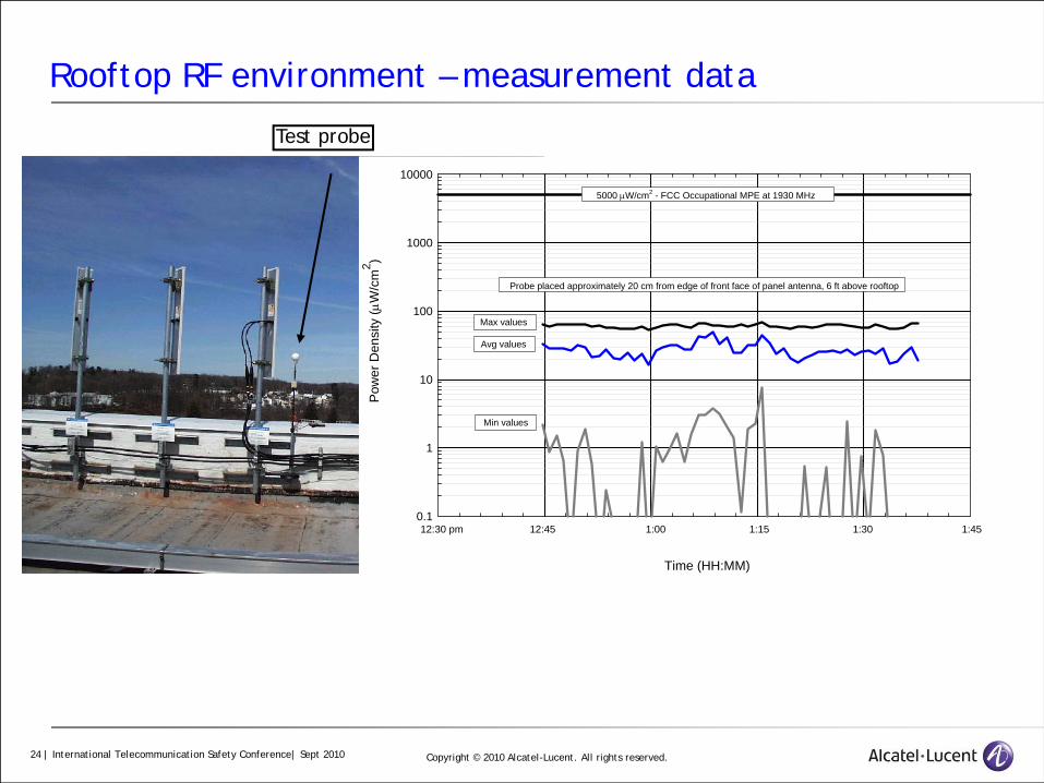
Rooftop RF environment – measurement data
Time (HH:MM)
Pow
er D
ensi
ty (μ
W/c
m2 )
0.1
1
10
100
1000
10000
12:30 pm 1:3012:45 1:00 1:15 1:45
Probe placed approximately 20 cm from edge of front face of panel antenna, 6 ft above rooftop
Min values
Avg values
Max values
5000 μW/cm2 - FCC Occupational MPE at 1930 MHz
Test probe

Copyright © 2010 Alcatel-Lucent. All rights reserved.25 | International Telecommunication Safety Conference| Sept 2010
Rooftop RF environment – measurement data
Time (HH:MM)
Pow
er D
ensi
ty (μ
W/c
m2 )
1
10
100
1000
FCC MPE - 2837 μW/cm2*
11:00 am 11:45 12:00 pm11:15 11:30
5000
Min valuesAvg valuesMax values
GSM850 and UMTS (3G)
Test probe

Copyright © 2010 Alcatel-Lucent. All rights reserved.26 | International Telecommunication Safety Conference| Sept 2010
Rooftop RF environment – RF Personal Monitor
Wear the monitor properlyOn your torso – not lower than belt levelOutside your clothingFacing outward – clip toward bodyFace toward source

Copyright © 2010 Alcatel-Lucent. All rights reserved.27 | International Telecommunication Safety Conference| Sept 2010
Rooftop RF environment – RF Personal Monitor
MONITOR WILL NOT DETECT SIGNALS FROM BEHIND•Monitor must face toward source•Do not remain motionless for extended periods if location of source unknown/questionable
+90/-65o
±90o

Copyright © 2010 Alcatel-Lucent. All rights reserved.28 | International Telecommunication Safety Conference| Sept 2010
Rooftop RF environment – RF Personal Monitor
Do not panic if monitor alarmsWhen monitor alarms (audible/vibrator)
- Move out of immediate area
- Move to an area where monitor no longer alarms
10 50 20010020
% STD

Copyright © 2010 Alcatel-Lucent. All rights reserved.29 | International Telecommunication Safety Conference| Sept 2010
Rooftop RF environment – RF Personal Monitor
Are antennas mounted above head height?
yes no
Can you maintainstand-off distances?
yes no
Can you confirm thatantennas are receive-only?
yes no
Can you power-downantennas?
yes no
Use personal monitoring
Power-down antennas
Maintain stand-offdistances
No otherrequirements
No otherrequirements
Are commercial broadcast antenna co-located?
yes no
Use personal monitoring
Visual Assessment Of Work Area
Copyright © 2010 Alcatel-Lucent. All rights reserved.30 | International Telecommunication Safety Conference| Sept 2010
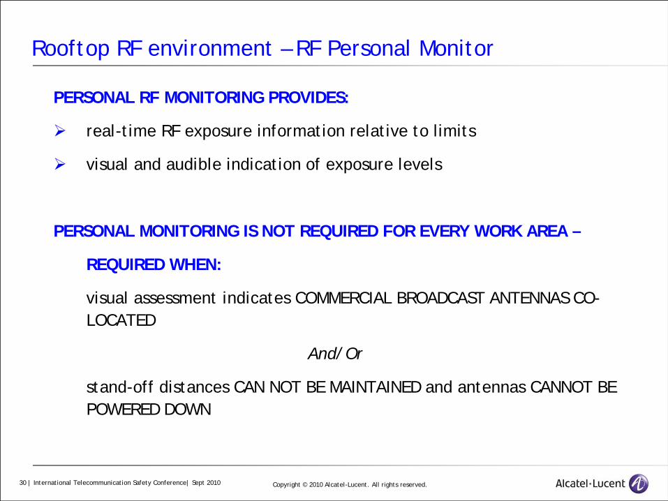
Rooftop RF environment – RF Personal Monitor
PERSONAL RF MONITORING PROVIDES:
real-time RF exposure information relative to limits
visual and audible indication of exposure levels
PERSONAL MONITORING IS NOT REQUIRED FOR EVERY WORK AREA –
REQUIRED WHEN:
visual assessment indicates COMMERCIAL BROADCAST ANTENNAS CO-LOCATED
And/Or
stand-off distances CAN NOT BE MAINTAINED and antennas CANNOT BE POWERED DOWN
Copyright © 2010 Alcatel-Lucent. All rights reserved.31 | International Telecommunication Safety Conference| Sept 2010
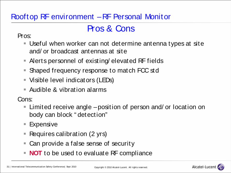
Rooftop RF environment – RF Personal Monitor
Pros:Useful when worker can not determine antenna types at site and/or broadcast antennas at siteAlerts personnel of existing/elevated RF fieldsShaped frequency response to match FCC stdVisible level indicators (LEDs) Audible & vibration alarms
Cons:Limited receive angle – position of person and/or location on body can block “detection”ExpensiveRequires calibration (2 yrs)Can provide a false sense of securityNOT to be used to evaluate RF compliance
Pros & Cons
Copyright © 2010 Alcatel-Lucent. All rights reserved.32 | International Telecommunication Safety Conference| Sept 2010
RF Signage

Copyright © 2010 Alcatel-Lucent. All rights reserved.33 | International Telecommunication Safety Conference| Sept 2010
RF Signage
DANGER & WARNING signs Reserved for situations where serious injury or
“death” can occur(TV Broadcast tower)
NOTICE signsStatement of policy
relating the safety of people/property
CAUTION signsIndicates potentially hazardous situations –
minor to moderate injury may occur

Copyright © 2010 Alcatel-Lucent. All rights reserved.34 | International Telecommunication Safety Conference| Sept 2010
RF Signage
General PublicExposure
(safety factor of 50)
OccupationalExposure
(safety factor of 10)
10 x Occ Exp

Copyright © 2010 Alcatel-Lucent. All rights reserved.35 | International Telecommunication Safety Conference| Sept 2010
RF Signage
INCORRECT use of signs

Copyright © 2010 Alcatel-Lucent. All rights reserved.36 | International Telecommunication Safety Conference| Sept 2010
RF SignageINCORRECT use of signs
INCORRECT wording

Copyright © 2010 Alcatel-Lucent. All rights reserved.37 | International Telecommunication Safety Conference| Sept 2010
RF Signage
CORRECT use of signs
Antennas behind RF transparent enclosure

Copyright © 2010 Alcatel-Lucent. All rights reserved.38 | International Telecommunication Safety Conference| Sept 2010
RF Signage
CORRECT use of signs
Specify Work Practices

Copyright © 2010 Alcatel-Lucent. All rights reserved.39 | International Telecommunication Safety Conference| Sept 2010
Conclusions

Copyright © 2010 Alcatel-Lucent. All rights reserved.40 | International Telecommunication Safety Conference| Sept 2010
Conclusions – Rooftop Wireless RF EnvironmentsRF environments where service/installation personnel have access must comply with FCC RF exposure limits for occupational exposure
time & spatial averagingtrained work force
Antennas used in rooftop installations, i.e., typically directional:most of energy emitted from antenna’s front surface – narrow vertical beamcompliance boundary (exclusion zone): for directional antennas – area in front of antenna & to a less degree, sides of antenna; areas above, below and behind of antenna are normally below FCC limits
RF instrumentation – broadband isotropic survey devices required for accurate assessment of complex RF environments & to determine compliance
RF personal monitors – pros & cons
RF Signage – Can be wrong!!!
TRAINING, training, training – this is the MOST important aspect of any RF safety program

Copyright © 2010 Alcatel-Lucent. All rights reserved.41 | International Telecommunication Safety Conference| Sept 2010
www.alcatel-lucent.comwww.alcatel-lucent.com