rf & microwave cable assemblies
TRANSCRIPT

RF & Microwave cable assembliesC291
AS 9100 CERTIFIED
B


www.radiall.com
B-3
CONTENTS
Introduction . . . . . . . . . . . . . . . . . . . . . . . . . . . . . . . . . . . . . . . . . . . . . . . . . . . . . . . . . . . . . . . . . . . . . . . . . . . . . . . . . . . . . . . . . . . . . . . . . . . . . . . . . . . . . . . . . . . . . . . . . . . . . . . . . . . . . . . . . . . . . . . . . . . . . . . . . . . B-4Specify the right cable for your application . . . . . . . . . . . . . . . . . . . . . . . . . . . . . . . . . . . . . . . . . . . . . . . . . . . . . . . . . . . . . . . . . . . . . . . . . . . . . . . . . . . . . . . . . . . . . . . . . . . . . . . . . . . . . . . . . B-5Finder guide cables vs insertion loss . . . . . . . . . . . . . . . . . . . . . . . . . . . . . . . . . . . . . . . . . . . . . . . . . . . . . . . . . . . . . . . . . . . . . . . . . . . . . . . . . . . . . . . . . . . . . . . . . . . . . . . . . . . . . . . . . B-6 to B-7
Flexible cables0.8/50 S cable (132390 type) . . . . . . . . . . . . . . . . . . . . . . . . . . . . . . . . . . . . . . . . . . . . . . . . . . . . . . . . . . . . . . . . . . . . . . . . . . . . . . . . . . . . . . . . . . . . . . . . . . . . . . . . . . . . . . . . . . . . . . . . . . . . . . . . . . . . . . B-81/50 S cable (50VMTX type) . . . . . . . . . . . . . . . . . . . . . . . . . . . . . . . . . . . . . . . . . . . . . . . . . . . . . . . . . . . . . . . . . . . . . . . . . . . . . . . . . . . . . . . . . . . . . . . . . . . . . . . . . . . . . . . . . . . . . . . . . . . . . . . . . . . . . . . B-81/75 S cable (75VMTX type) . . . . . . . . . . . . . . . . . . . . . . . . . . . . . . . . . . . . . . . . . . . . . . . . . . . . . . . . . . . . . . . . . . . . . . . . . . . . . . . . . . . . . . . . . . . . . . . . . . . . . . . . . . . . . . . . . . . . . . . . . . . . . . . . . . . . . . . . B-92/50 S cable (RG178-KX21A-RG178 non mag) . . . . . . . . . . . . . . . . . . . . . . . . . . . . . . . . . . . . . . . . . . . . . . . . . . . . . . . . . . . . . . . . . . . . . . . . . . . . . . . . . . . . . . . . . . . . . . . . . . . . . . . B-9 to B-102/50 D cable (124416 type) . . . . . . . . . . . . . . . . . . . . . . . . . . . . . . . . . . . . . . . . . . . . . . . . . . . . . . . . . . . . . . . . . . . . . . . . . . . . . . . . . . . . . . . . . . . . . . . . . . . . . . . . . . . . . . . . . . . . . . . . . . . . . . . . . . . . . . . B- 102/75 S cable (296775 type) . . . . . . . . . . . . . . . . . . . . . . . . . . . . . . . . . . . . . . . . . . . . . . . . . . . . . . . . . . . . . . . . . . . . . . . . . . . . . . . . . . . . . . . . . . . . . . . . . . . . . . . . . . . . . . . . . . . . . . . . . . . . . . . . . . . . . . . . B- 1 12.6/50 S cable (RG174-KX3B-RG316-KX22A) . . . . . . . . . . . . . . . . . . . . . . . . . . . . . . . . . . . . . . . . . . . . . . . . . . . . . . . . . . . . . . . . . . . . . . . . . . . . . . . . . . . . . . . . . . . . . . . . . . . . . . . . . . B-11 to B-122.6/50 D cable (RD316) . . . . . . . . . . . . . . . . . . . . . . . . . . . . . . . . . . . . . . . . . . . . . . . . . . . . . . . . . . . . . . . . . . . . . . . . . . . . . . . . . . . . . . . . . . . . . . . . . . . . . . . . . . . . . . . . . . . . . . . . . . . . . . . . . . . . . . . . . . . . . B- 132.6/75 S cable (RG179) . . . . . . . . . . . . . . . . . . . . . . . . . . . . . . . . . . . . . . . . . . . . . . . . . . . . . . . . . . . . . . . . . . . . . . . . . . . . . . . . . . . . . . . . . . . . . . . . . . . . . . . . . . . . . . . . . . . . . . . . . . . . . . . . . . . . . . . . . . . . . . B- 154.6/75 D cable (HD 0.6/2.8-mini RG59 type) . . . . . . . . . . . . . . . . . . . . . . . . . . . . . . . . . . . . . . . . . . . . . . . . . . . . . . . . . . . . . . . . . . . . . . . . . . . . . . . . . . . . . . . . . . . . . . . . . . . . . . . . . . . . . . . . . . . B- 155/50 S cable (RG58-KX15) . . . . . . . . . . . . . . . . . . . . . . . . . . . . . . . . . . . . . . . . . . . . . . . . . . . . . . . . . . . . . . . . . . . . . . . . . . . . . . . . . . . . . . . . . . . . . . . . . . . . . . . . . . . . . . . . . . . . . . . . . . . . . . . . . . . . . . . . . . B- 165/50 D cable (RG142-RG223-RG400-KX23) . . . . . . . . . . . . . . . . . . . . . . . . . . . . . . . . . . . . . . . . . . . . . . . . . . . . . . . . . . . . . . . . . . . . . . . . . . . . . . . . . . . . . . . . . . . . . B-16 and B-18 to B-196/75 S cable (RG59-KX6A) . . . . . . . . . . . . . . . . . . . . . . . . . . . . . . . . . . . . . . . . . . . . . . . . . . . . . . . . . . . . . . . . . . . . . . . . . . . . . . . . . . . . . . . . . . . . . . . . . . . . . . . . . . . . . . . . . . . . . . . . . . . . . . . . . . . . . . . . . B-216/75 D cable (HD 0.8/3.7-RG59 type) . . . . . . . . . . . . . . . . . . . . . . . . . . . . . . . . . . . . . . . . . . . . . . . . . . . . . . . . . . . . . . . . . . . . . . . . . . . . . . . . . . . . . . . . . . . . . . . . . . . . . . . . . . . . . . . . . . . . . . . . . . . . B-227/75 D cable (HD 1.0/4.8-RG6 type) . . . . . . . . . . . . . . . . . . . . . . . . . . . . . . . . . . . . . . . . . . . . . . . . . . . . . . . . . . . . . . . . . . . . . . . . . . . . . . . . . . . . . . . . . . . . . . . . . . . . . . . . . . . . . . . . . . . . . . . . . . . . . . B-2210/50 S cable (RG213-KX4) . . . . . . . . . . . . . . . . . . . . . . . . . . . . . . . . . . . . . . . . . . . . . . . . . . . . . . . . . . . . . . . . . . . . . . . . . . . . . . . . . . . . . . . . . . . . . . . . . . . . . . . . . . . . . . . . . . . . . . . . . . . . . . . . . . . . . . . . B-2310/50 D cable (RG393) . . . . . . . . . . . . . . . . . . . . . . . . . . . . . . . . . . . . . . . . . . . . . . . . . . . . . . . . . . . . . . . . . . . . . . . . . . . . . . . . . . . . . . . . . . . . . . . . . . . . . . . . . . . . . . . . . . . . . . . . . . . . . . . . . . . . . . . . . . . . . . B-2311/50 D cable (RG214-KX13) . . . . . . . . . . . . . . . . . . . . . . . . . . . . . . . . . . . . . . . . . . . . . . . . . . . . . . . . . . . . . . . . . . . . . . . . . . . . . . . . . . . . . . . . . . . . . . . . . . . . . . . . . . . . . . . . . . . . . . . . . . . . . . . . . . . . . . . B-2511/75 D cable (RG216) . . . . . . . . . . . . . . . . . . . . . . . . . . . . . . . . . . . . . . . . . . . . . . . . . . . . . . . . . . . . . . . . . . . . . . . . . . . . . . . . . . . . . . . . . . . . . . . . . . . . . . . . . . . . . . . . . . . . . . . . . . . . . . . . . . . . . . . . . . . . . . . . B-26
ECO low loss flexible cables2.6/50 S cable (ECO316-ECO316X) . . . . . . . . . . . . . . . . . . . . . . . . . . . . . . . . . . . . . . . . . . . . . . . . . . . . . . . . . . . . . . . . . . . . . . . . . . . . . . . . . . . . . . . . . . . . . . . . . . . . . . . . . . . . . . . . . . . . B-12 to B-132.6/50 D cable (ECO316D-ECO316DX) . . . . . . . . . . . . . . . . . . . . . . . . . . . . . . . . . . . . . . . . . . . . . . . . . . . . . . . . . . . . . . . . . . . . . . . . . . . . . . . . . . . . . . . . . . . . . . . . . . . . . . . . . . . . . . . . . . . . . . . . . . . . B- 145/50 D cable (ECO142-ECO142X-Power142) . . . . . . . . . . . . . . . . . . . . . . . . . . . . . . . . . . . . . . . . . . . . . . . . . . . . . . . . . . . . . . . . . . . . . . . . . . . . . . . . . . . . . . . . . . . . . . . . . . . . . . . . B-17 to B-186/50 D cable (ECO230) . . . . . . . . . . . . . . . . . . . . . . . . . . . . . . . . . . . . . . . . . . . . . . . . . . . . . . . . . . . . . . . . . . . . . . . . . . . . . . . . . . . . . . . . . . . . . . . . . . . . . . . . . . . . . . . . . . . . . . . . . . . . . . . . . . . . . . . . . . . . . . B-2010/50 D cable (ECO393-ECO393X). . . . . . . . . . . . . . . . . . . . . . . . . . . . . . . . . . . . . . . . . . . . . . . . . . . . . . . . . . . . . . . . . . . . . . . . . . . . . . . . . . . . . . . . . . . . . . . . . . . . . . . . . . . . . . . . . . . . . . . . . . . . . . . . B-24
LMR low loss flexible cables5/50 D cable (LMR200) . . . . . . . . . . . . . . . . . . . . . . . . . . . . . . . . . . . . . . . . . . . . . . . . . . . . . . . . . . . . . . . . . . . . . . . . . . . . . . . . . . . . . . . . . . . . . . . . . . . . . . . . . . . . . . . . . . . . . . . . . . . . . . . . . . . . . . . . . . . . B-2010.3/50 D cable (LMR400) . . . . . . . . . . . . . . . . . . . . . . . . . . . . . . . . . . . . . . . . . . . . . . . . . . . . . . . . . . . . . . . . . . . . . . . . . . . . . . . . . . . . . . . . . . . . . . . . . . . . . . . . . . . . . . . . . . . . . . . . . . . . . . . . . . . . . . . . . . B-2515.2/50 D cable (LMR600) . . . . . . . . . . . . . . . . . . . . . . . . . . . . . . . . . . . . . . . . . . . . . . . . . . . . . . . . . . . . . . . . . . . . . . . . . . . . . . . . . . . . . . . . . . . . . . . . . . . . . . . . . . . . . . . . . . . . . . . . . . . . . . . . . . . . . . . . . . B-26
SHF Ultra low loss cables . . . . . . . . . . . . . . . . . . . . . . . . . . . . . . . . . . . . . . . . . . . . . . . . . . . . . . . . . . . . . . . . . . . . . . . . . . . . . . . . . . . . . . . . . . . . . . . . . . . . . . . . . . . . . . B-37 to B-38
Corrugated cablesCable 1/4" spiral (HCF 1/4"-50 AlCu) . . . . . . . . . . . . . . . . . . . . . . . . . . . . . . . . . . . . . . . . . . . . . . . . . . . . . . . . . . . . . . . . . . . . . . . . . . . . . . . . . . . . . . . . . . . . . . . . . . . . . . . . . . . . . . . . . . . . . . . . . . . . B-27Cable 3/8" spiral (HCF 3/8" CuH-50 AlCu) . . . . . . . . . . . . . . . . . . . . . . . . . . . . . . . . . . . . . . . . . . . . . . . . . . . . . . . . . . . . . . . . . . . . . . . . . . . . . . . . . . . . . . . . . . . . . . . . . . . . . . . . . . . . . . . . . . . . . B-27Cable 1/2" spiral (HCF 1/2" CuH-50 AlCu) . . . . . . . . . . . . . . . . . . . . . . . . . . . . . . . . . . . . . . . . . . . . . . . . . . . . . . . . . . . . . . . . . . . . . . . . . . . . . . . . . . . . . . . . . . . . . . . . . . . . . . . . . . . . . . . . . . . . . . B-28
Semi-rigid and hand-formable cables.047" cable (SR copper-SR tinned copper) . . . . . . . . . . . . . . . . . . . . . . . . . . . . . . . . . . . . . . . . . . . . . . . . . . . . . . . . . . . . . . . . . . . . . . . . . . . . . . . . . . . . . . . . . . . . . . . . . . . . . . . B-28 to B-29.085" cable (Handformable unjacketed-SR RG405/KS1-SR tinned copper-SR non magnetic-SR aluminium) . . . . . . . . . . . . . . . . . . . . . B-29 to B-31.141" cable (Handformable unjacketed-Handformable FEP jacketed-SR RG402/KS2
SR tinned copper-SR silvered copper-SR non magnetic-SR aluminium) . . . . . . . . . . . . . . . . . . . . . . . . . . . . . . . . . . . . . . . . . . . . . . . . . . B-32 to B-35.250" cable (SR RG401/KS3-SR aluminium) . . . . . . . . . . . . . . . . . . . . . . . . . . . . . . . . . . . . . . . . . . . . . . . . . . . . . . . . . . . . . . . . . . . . . . . . . . . . . . . . . . . . . . . . . . . . . . . . . . . . . . . . B-35 to B-36
Pages
Cab
le a
ssem
blie
s
Radiall cable groups
Example for flexible cables: 5/50 S
Example for corrugated cables: 1/2 spiral
Example for semi-rigid & handformable cables: .141"
cable outer diameter in mm (2.6 mm, 5 mm, 10 mm, 11 mm,…)characteristic impedance (50Ω, 75Ω)number of shields (S=single, D=double)
cable outer conductor diameter in fraction of inch (1/4", 3/8", 1/2",…)
cable outer conductor diameter in inches(.085", .141", .250",…)

www.radiall.com
B-4
Radiall is highly recognized as a leading manufacturer of coaxial connectors, cable and cable assemblies.
Radiall has the best manufacturing technology and processes. As a result, we are one of the only manufacturers that have fully mastered foam PTFE wrapping technology. This capability enables us to supply cable assemblies featuring the highest level of performance, stability and repeatability.
In addition, Radiall has high precision stripping and cutting machines, soldering and cleaning equipment.
Radiall offers five standard ranges of cable for a wide variety of applications for the telecom, military, instrumentation, medical and broadcast markets.
Cab
le a
ssem
blie
s INTRODUCTION
REqUIREmENTS fOR DESIgNINg a CUSTOm CablE-aSSEmblyStart with identifying the needed components and the required information for your cable assembly:
- coaxial cable (p/n or description)- connector 1 (p/n or description)- optional boot 1 or heatshrink sleeve 1 (p/n or description)- connector 2 (p/n or description)- optional boot or sleeve 2 (p/n or description)- length: radiall standard = overall length (or please specify if length between reference planes)
+ length tolerance (radiall standard = ±2%)- marking: Radiall standard = RADIALL + p/n + batch code (or please specify if different)- connectors orientation (if needed for right-angle or panel connectors)
If you need a pigtail, you will also need the following dimensions and information:
- stripping A dimension- stripping B dimension- stripping C dimension- tinned inner conductor (if needed)- tinned braid (if needed)

www.radiall.com
B-5
Cab
le a
ssem
blie
sSpECIfy ThE RIghT CablE fOR yOUR applICaTION
RG flexible cablesStandardized by MIL-C-17 US government specification since the 40’s, these familiar P/N’s are mainly used for military RF and microwave applications.
Every electrical, mechanical and environmental performance is controlled and in compliance with the relevant standard.
KX cables are equivalent to RG cables under french standards (NF).
These cables will be of perfect use with dynamic applications (bending moment) or needing flexibility for ease of connection.
RADIALL Eco-friendly low loss cablesThese high performance custom cables have been designed for optimized electrical and environmental requirements.
Cost effective compared with RG cables, they are the perfect alternative to fulfill your needs.
These cables are halogen free and flame retardant to meet safety environmental regulations.
Hand-formable cablesUsing a tin-dipped braid technology, these cables are a compromise between performance and flexibility.
They allow easy routing during installation (without spring-back effect) and multiple repositions on site.
Preserving high performance level (low loss and high shielding efficiency,) they are a good cost-effective alternative to semi-rigid cables.
Corrugated cablesThe outer conductor of these cables is constituted of a corrugated tube (spiral or ringed winding).
This construction allows perfect shielding and some bendability while respecting large bending radius.
The hight performance level of these cables enable them to be used in outdoor long length transmission lines.
Semi-rigid cablesThe solid tubing technology allows definitive and high precision forming. These cables use only high grade insulation material and feature optimal shielding effectiveness. They provide the highest electrical performance (e.g: the lowest insertion loss)
KS cables are equivalent to semi-rigid RG cables under French standards (NF).
These cables can also be used for cosmetic aspect where straight and clear cable path must be demonstrated.
flexibility attenuation

www.radiall.com
B-6
Cab
le a
ssem
blie
s fINDER gUIDE - CablES VS INSERTION lOSS
STaNDaRD flEXIblE CablESCable group Cable p/n Cable type
1 GHz(VHF/UHF)dB/m dB/ft
2 GHz(band L)dB/m dB/ft
3 GHz(band S)dB/m dB/ft
6 GHz(band C)dB/m dB/ft
8 GHz(band C)dB/m dB/ft
12.4 GHz(band X)dB/m dB/ft
18 GHz(band Ku)dB/m dB/ft
0.8/50 S C291 042 066 132390 type 2.41/0.73 3.51/1.06 4.93/1.491/50 S C291 050 066 50 VMTX type 2.12/0.64 3.36/1.02 4.45/1.351/75 S C291 055 076 75 VMTX type 2.22/0.67 3.14/0.95
2/50 SC291 145 007/017 RG178/KX21 1.54/0.47 2.20/0.67 2.72/0.82
C291 140 087 RG178 non mag type 1.34/0.41 1.92/0.58 2.37/0.722/50 D C291 146 087 124416 type 1.34/0.41 1.92/0.58 2.37/0.722/75 S C291 147 060 296775 type 1.38/0.42 1.98/0.60 2.46/0.75
2.6/50 SC291 150 000/010 RG174/KX3B 1.07/0.32C291 170 007/017 RG316/KX22A 0.86/0.26 1.24/0.38 1.54/0.47
2.6/50 D C291 185 067 RD316 0.86/0.26 1.24/0.38 1.54/0.472.6/75 S C291 210 007 RG179 0.95/0.29 1.37/0.41 1.70/0.515/50 S C291 305 000/010 RG58/KX15 0.67/0.20
5/50 D
C291 320 007 RG142 0.44/0.13 0.65/0.20 0.81/0.25 1.22/0.37 1.45/0.44 1.90/0.58C291 330 000 RG223 0.46/0.14 0.67/0.20 0.85/0.26 1.27/0.38 1.51/0.46 1.97/0.60C291 324 007 RG400 0.52/0.16 0.76/0.23 0.95/0.29 1.42/0.43 1.68/0.51 2.19/0.66C291 322 017 KX23 0.48/0.14 0.70/0.21 0.89/0.27 1.35/0.41 1.61/0.49C291 325 270 POWER142 0.41/0.12 0.58/0.18 0.72/0.22
6/75 SC291 360 000 RG59 0.44/0.13C291 361 012 KX6A 0.48/0.15
10/50 S C291 510 000/010 RG213/KX4 0.24/0.0710/50 D C291 511 007 RG393 0.23/0.07 0.35/0.11 0.45/0.14 0.71/0.21 0.86/0.26 1.07(11)/0.32(11)11/50 D C291 600 000/010 RG214/KX13 0.24/0.07 0.36/0.11 0.47/0.14 0.73/0.22 0.89/0.27 1.1(11)/0.33(11)11/75 D C291 610 000 RG216 0.32/0.10 0.48/0.14 0.60/0.18
(11) = 11 GHz
lOW-lOSS ECO-fRIENDly flEXIblE CablES (alternative to RG cables - in accordance with RoHS regulation)
Cable group Cable p/n Cable type
1 GHz(VHF/UHF)dB/m dB/ft
2 GHz(band L)dB/m dB/ft
3 GHz(band S)dB/m dB/ft
6 GHz(band C)dB/m dB/ft
8 GHz(band C)dB/m dB/ft
12.4 GHz(band X)dB/m dB/ft
18 GHz(band Ku)dB/m dB/ft
2.6/50 SC291 999 904 ECO316 0.76/0.23 1.09/0.33 1.34/0.41C291 171 089 ECO316X 0.96/0.29 1.45/0.44 1.85/0.56
2.6/50 DC291 999 905 ECO316D 0.76/0.23 1.09/0.33 1.34/0.41C291 217 020 ECO316DX 0.86/0.26 1.30/0.40 1.68/0.51 2.64/0.80
5/50 DC291 325 290 ECO142 0.41/0.12 0.58/0.18 0.72/0.22C291 320 180 ECO142X 0.54/0.16 0.83/0.25 1.07/0.32 1.70/0.51
6/50 D C291 326 490 ECO230 0.28/0.08 0.40/0.12 0.50/0.15 0.59/0.18(4)
10/50 DC291 491 060 ECO393 0.16/0.05 0.24/0.07 0.30/0.09C291 512 020 ECO393X 0.29/0.09 0.47/0.14 0.64/0.19 1.11/0.34
(4) = 4 GHz
lOW-lOSS flEXIblE CablESCable group Cable p/n Cable type
1 GHz(VHF/UHF)dB/m dB/ft
2 GHz(band L)dB/m dB/ft
3 GHz(band S)dB/m dB/ft
6 GHz(band C)dB/m dB/ft
8 GHz(band C)dB/m dB/ft
12.4 GHz(band X)dB/m dB/ft
18 GHz(band Ku)dB/m dB/ft
LMR200 C291 316 070 LMR200 0.34/0.10 0.49/0.15 0.61/0.18 0.88/0.27LMR400 C291 516 070 LMR400 0.14/0.04 0.20/0.06 0.25/0.07 0.37/0.11LMR600 C291 626 070 LMR600 0.09/0.03 0.13/0.04 0.16/0.05 0.25/0.07
: Service+ program fast delivery

www.radiall.com
B-7
STaNDaRD flEXIblE hD CablESCable group Cable p/n Cable type
1 GHz(VHF/UHF)dB/m dB/ft
2 GHz(band L)dB/m dB/ft
3 GHz(band S)dB/m dB/ft
4.5 GHz(band C)dB/m dB/ft
8 GHz(band C)dB/m dB/ft
12.4 GHz(band X)dB/m dB/ft
18 GHz(band Ku)dB/m dB/ft
4.6/75 D C291 333 039 HD 0.6/2.8 mini RG59 type 0.34/0.10 0.50/0.15 0.62/0.19
6/75 D C291 360 093 HD 0.8/3.7 RG59 type 0.25/0.07 0.35/0.11 0.44/0.13 0.54/0.16
7/75 D C291 384 083 HD 1.0/4.8 RG6 type 0.19/0.06 0.28/0.08 0.35/0.11 0.44/0.13
CORRUgaTED CablES (spiral outer shielding)
Cable group Cable p/n Cable type
2 GHz(band L)dB/m dB/ft
3 GHz(band S)dB/m dB/ft
6 GHz(band C)dB/m dB/ft
8 GHz(band C)dB/m dB/ft
12.4 GHz(band X)dB/m dB/ft
18 GHz(band Ku)dB/m dB/ft
20 GHz(band Ku)dB/m dB/ft
Celiflex 1/4" C291 993 170 HCF 1/4"-50 AlCu 0.27/0.08 0.34/0.10 0.51/0.15 0.60/0.18 0.78/0.24 0.99/0.30 1.06/0.32
Celiflex 3/8" C291 996 170 HCF 3/8" CuH-50 AlCu 0.19/0.06 0.24/0.07 0.36/0.11 0.43/0.13 0.54(11.7)/ 0.16(11.7)
Celiflex 1/2" C291 994 170 HCF 1/2" CuH-50 AlCu 0.16/0.05 0.20/0.06 0.30/0.09 0.36/0.11 0.42(10)/ 0.13(11.7)
(11.7) = 11.7 GHz (10) = 10 GHz
haND-fORmablE aND SEmI-RIgID CablESCable group Cable p/n Cable type
2 GHz(band L)dB/m dB/ft
3 GHz(band S)dB/m dB/ft
6 GHz(band C)dB/m dB/ft
8 GHz(band C)dB/m dB/ft
12.4 GHz(band X)dB/m dB/ft
18 GHz(band Ku)dB/m dB/ft
20 GHz(band Ku)dB/m dB/ft
.047"C291 855 001 SR copper 1.64/0.50 2.03/0.61 2.93/0.89 3.43/1.04 4.73/1.32 5.39/1.63 5.72/1.73C291 855 065 SR tinned copper 1.64/0.50 2.03/0.61 2.93/0.89 3.43/1.04 4.73/1.32 5.39/1.63 5.72/1.73
.085"
C291 844 065 Handformable unjacketed 0.97/0.29 1.21/0.37 1.78/0.54 2.10/0.64 2.71/0.82 3.39/1.03 3.62/1.10
C291 850 001 SR RG405/KS1 0.94/0.29 1.18/0.36 1.73/0.53 2.05/0.62 2.64/0.80 3.31/1.00 3.53/1.07C291 850 005 SR tinned copper 0.94/0.29 1.18/0.36 1.73/0.53 2.05/0.62 2.64/0.80 3.31/1.00 3.53/1.07C291 851 001 SR non magnetic 0.94/0.29 1.18/0.36 1.73/0.53 2.05/0.62 2.64/0.80 3.31/1.00 3.53/1.07C291 844 187 SR aluminium 0.98/0.30 1.22/0.37 1.80/0.54 2.12/0.64 2.73/0.83 3.41/1.03 3.64/1.10
.141"
C291 864 065 Handformable unjacketed 0.57/0.17 0.72/0.22 1.09/0.33 1.30/0.39 1.71/0.52 2.18/0.66 2.34/0.71
C291 866 378 Handformable FEP jacketed 0.63/0.19 0.80/0.24 1.20/0.36 1.42/0.43 1.87/0.57 2.37/0.72 2.54/0.77
C291 860 001 SR RG402/KS2 0.50/0.15 0.64/0.19 0.97/0.30 1.17/0.35 1.55/0.47 1.99/0.06 2.14/0.65C291 862 005 SR tinned copper 0.50/0.15 0.64/0.19 0.97/0.30 1.17/0.35 1.55/0.47 1.99/0.06 2.14/0.65C291 861 066 SR silvered copper 0.50/0.15 0.64/0.19 0.97/0.30 1.17/0.35 1.55/0.47 1.99/0.06 2.14/0.65C291 861 061 SR non magnetic 0.50/0.15 0.64/0.19 0.97/0.30 1.17/0.35 1.55/0.47 1.99/0.60 2.14/0.65C291 864 187 SR aluminium 0.53/0.16 0.67/0.20 1.02/0.31 1.23/0.37 1.62/0.49 2.08/0.63 2.23/0.38
.250"C291 870 001 SR RG401/KS3 0.31/0.09 0.41/0.12 0.64/0.20 0.79/0.24 1.08/0.33 1.42/0.43 1.54/0.47C291 874 187 SR aluminium 0.33/0.10 0.43/0.13 0.68/0.21 0.83/0.25 1.13/0.34 1.48/0.45 1.60/0.49
: Service+ program fast delivery
Cab
le a
ssem
blie
sfINDER gUIDE - CablES VS INSERTION lOSS

www.radiall.com
B-8
CONSTRUCTION / DImENSIONS material mm inches
center conductor solid SPC(1) 0.16 0.006dielectric solid PFA(2) 0.50 0.020
inner shield SPC(1) braid 0.70 0.028outer shield - - -
jacket white FEP(3) 0.83 max 0.033 max
ElECTRICal ChaRaCTERISTICS characteristic impedance 50Ω ± 3Ωoperating frequency range DC - 3 GHz
shielding effectiveness 40 dBvoltage withstanding 18 000 V rms
peak power 6 kWcapacitance 98.7 pF / m 29.9 pF / ft
velocity of propagation 69 % (4.8 ns / m)
mEChaNICal ChaRaCTERISTICS recommended minimum
bending radius 4 mm 0.157 inch
weight 1.8 g / m 0.001 Ibs / ft
ENVIRONmENTal ChaRaCTERISTICS operating temperature range -50 / +200 °C -58 / +392 °F
fire resistance yes (UL94V0)halogen free no
fREqUENCy / aTTENUaTION (typ.) / CW maX pOWER (sea level / 40 °C)
GHz dB / m dB / ft Watts0.1 0.64 0.19 450.2 0.88 0.27 340.3 1.90 0.58 280.4 1.28 0.39 220.5 1.48 0.45 201.0 2.41 0.73 141.5 3.03 0.92 122.0 3.51 1.06 102.5 4.20 1.27 93.0 4.93 1.49 8
(1) SPC = Silver Plated Copper(2) PFA = PerFluoroAlkoxy(3) FEP = Fluorinated Ethylene Propylene
CONSTRUCTION / DImENSIONS material mm inches
center conductor solid SPC(1) 0.17 0.007dielectric solid PTFE(2) 0.52 0.020
inner shield SPC(1) braid 0.70 0.028outer shield - - -
jacket white FEP(3) 1.17 0.046
ElECTRICal ChaRaCTERISTICS characteristic impedance 50Ω ± 5Ωoperating frequency range DC - 3 GHz
shielding effectiveness 40 dBvoltage withstanding 19 000 V rms
peak power 7 kWcapacitance 94 pF / m 28.5 pF / ft
velocity of propagation 69 % (4.8 ns / m)
mEChaNICal ChaRaCTERISTICS recommended minimum
bending radius 6 mm 0.236 inch
weight 3 g / m 0.002 Ibs / ft
ENVIRONmENTal ChaRaCTERISTICS operating temperature range -90 / +200 °C -130 / +392 °F
fire resistance yes (UL94V0)halogen free no
fREqUENCy / aTTENUaTION (typ.) / CW maX pOWER (sea level / 40 °C)
GHz dB / m dB / ft Watts0.1 0.54 0.16 820.2 0.80 0.24 580.3 1.01 0.31 450.4 1.20 0.36 390.5 1.37 0.42 341.0 2.12 0.64 251.5 2.76 0.84 212.0 3.36 1.02 172.5 3.91 1.19 153.0 4.45 1.35 14
attenuation calculation (dB/m) (1.51 x √f GHz) + (0.61 x f GHz)
(1) SPC = Silver Plated Copper(2) PTFE = PolyTetraFluoroEthylene(3) FEP = Fluorinated Ethylene Propylene
The very small outer diameter and bending moment of this cable allow very easy routing during installation.
Its very light weight makes it perfect to be used in all miniature and space saving applications.
The insulation and jacket materials allow this cable to be used in severe thermal conditions.
The very small outer diameter and bending moment of this cable allow very easy routing during installation.
Its very light weight makes it perfect to be used in all miniature and space saving applications.
The insulation and jacket materials allow this cable to be used in severe thermal conditions.
APPLICATION NOTE APPLICATION NOTE
Cab
le a
ssem
blie
s flEXIblE CablE 0.8/50 S(132390 type)
flEXIblE CablE 1/50 S(50 VMTX type)
p/N: C291 042 066 p/N: C291 050 066
Note: typical attenuation for a couple of connectors (dB) = 0.045 x √f (GHz)

www.radiall.com
B-9
CONSTRUCTION / DImENSIONS material mm inches
center conductor solid SPCCS(1) 0.10 0.004dielectric solid PTFE(2) 0.57 0.022
inner shield SPC(3) braid 0.80 0.031outer shield - - -
jacket white FEP(4) 1.22 0.048
ElECTRICal ChaRaCTERISTICS characteristic impedance 80Ω ± 8Ωoperating frequency range DC - 2 GHz
shielding effectiveness 40 dBvoltage withstanding 2 600 V rms
peak power 0.9 kWcapacitance 60 pF / m 18.3 pF / ft
velocity of propagation 69 % (4.8 ns / m)
mEChaNICal ChaRaCTERISTICS recommended minimum
bending radius 6.1 mm 0.240 inch
weight 3 g / m 0.002 Ibs / ft
ENVIRONmENTal ChaRaCTERISTICS operating temperature range -90 / +200 °C -130 / +392 °F
fire resistance yes (UL94V0)halogen free no
fREqUENCy / aTTENUaTION (typ.) / CW maX pOWER (sea level / 40 °C)
GHz dB / m dB / ft Watts0.1 0.70 0.21 860.2 0.99 0.30 640.3 1.21 0.37 500.4 1.40 0.42 410.5 1.57 0.47 380.6 1.71 0.52 350.8 1.98 0.60 301.0 2.22 0.67 261.5 2.71 0.82 212.0 3.14 0.95 18
attenuation calculation (dB/m) (2.21 x √f GHz) + (0.005 x f GHz)
(1) SPCCS = Silver Plated Copper covered steel(2) PTFE = PolyTetraFluoroEthylene(3) SPC = Silver Plated Copper(4) FEP = Fluorinated Ethylene Propylene
Due to its 75 ohms characteristic impedance, this cable is rather dedicated to TV/Video application.The very small outer diameter and bending moment allow very easy routing during installation.Its very light weight makes it perfect to be used in all miniature, space saving and dynamic applications.Usable in severe thermal conditions.
APPLICATION NOTE
flEXIblE CablE 1/75 S(75 VMTX type)
p/N: C291 055 076
Cab
le a
ssem
blie
s
CONSTRUCTION / DImENSIONS material mm inches
center conductor stranded SPCCS(1) 0.30 0.012dielectric solid PTFE(2) 0.84 0.033
inner shield SPC(3) braid 1.30 0.051outer shield - - -
jacket brown FEP(4) 1.78 0.07
ElECTRICal ChaRaCTERISTICS characteristic impedance 50Ω ± 3Ωoperating frequency range DC - 3 GHz
shielding effectiveness 40 dBvoltage withstanding 2 000 V rms
peak power 1 kWcapacitance 96 pF / m 29 pF / ft
velocity of propagation 70 % (4.8 ns / m)
mEChaNICal ChaRaCTERISTICS recommended minimum
bending radius 7 mm 0.275 inch
weight 8 g / m 0.0053 Ibs / ft
ENVIRONmENTal ChaRaCTERISTICS operating temperature range -55 / +200 °C -67 / +392 °F
fire resistance yes (CSA FT6 / IEC 332-2)halogen free no
fREqUENCy / aTTENUaTION (typ.) / CW maX pOWER (sea level / 25 °C)
GHz dB / m dB / ft Watts0.1 0.48 0.14 1900.2 0.68 0.21 1340.3 0.83 0.25 1100.5 1.08 0.33 851.0 1.54 0.47 601.5 1.90 0.57 492.0 2.20 0.67 422.5 2.47 0.75 383.0 2.72 0.82 35
attenuation calculation (dB/m) (1.50 x √f GHz) + (0.04 x f GHz)power calculation (W) 60 / √f GHz
(1) SPCCS = Silver Plated Copper covered steel(2) PTFE = PolyTetraFluoroEthylene(3) SPC = Silver Plated Copper(4) FEP = Fluorinated Ethylene Propylene
Due to its small diameter and its stranded inner conductor, RG 178 / KX21A is used for applications requiring high flexibility.
Its very low bending moment allows an easy routing during installation.
The insulation and jacket materials allow this cable to be used in severe thermal conditions.
APPLICATION NOTE
flEXIblE CablE 2/50 S(RG178 - KX21A)
p/N: C291 145 007(MIL-C-17/93-RG178)
p/N: C291 145 017(NF-C-93/550-KX21A)
: Service+ program = fast deliveryNote: typical attenuation for a couple of connectors (dB) = 0.045 x √f (GHz)
www.radiall.com
B-10
CONSTRUCTION / DImENSIONS material mm inches
center conductor solid SPC(1) 0.29 0.011dielectric solid PTFE(2) 0.84 0.033
inner shield SPC braid 1.27 0.050outer shield SPC braid 1.60 0.063
jacket brown FEP(3) 2.10 0.083
ElECTRICal ChaRaCTERISTICS characteristic impedance 50Ω ± 2Ωoperating frequency range DC - 3 GHz
shielding effectiveness 80 dBvoltage withstanding 3 000 V rms
peak power 1.8 kWcapacitance 105 pF / m 32 pF / ft
velocity of propagation 69 % (4.8 ns / m)
mEChaNICal ChaRaCTERISTICS recommended minimum
bending radius 12.5 mm 0.49 inch
weight 12.5 g / m 0.0083 Ibs / ft
ENVIRONmENTal ChaRaCTERISTICS operating temperature range -90 / +200 °C -130 / +392 °F
fire resistance yes (UL94V0)halogen free no
fREqUENCy / aTTENUaTION (typ.) / CW maX pOWER (sea level / 40 °C)
GHz dB / m dB / ft Watts0.1 0.42 0.13 2530.2 0.59 0.18 1790.3 0.72 0.22 1460.5 0.94 0.28 1131.0 1.34 0.41 801.5 1.65 0.50 652.0 1.92 0.58 572.5 2.16 0.65 513.0 2.37 0.72 46
attenuation calculation (dB/m) (1.30 x √f GHz) + (0.04 x f GHz)power calculation (W) 80 / √f GHz
(1) SPC = Silver Plated Copper(2) PTFE = PolyTetraFluoroEthylene(3) FEP = Fluorinated Ethylene Propylene
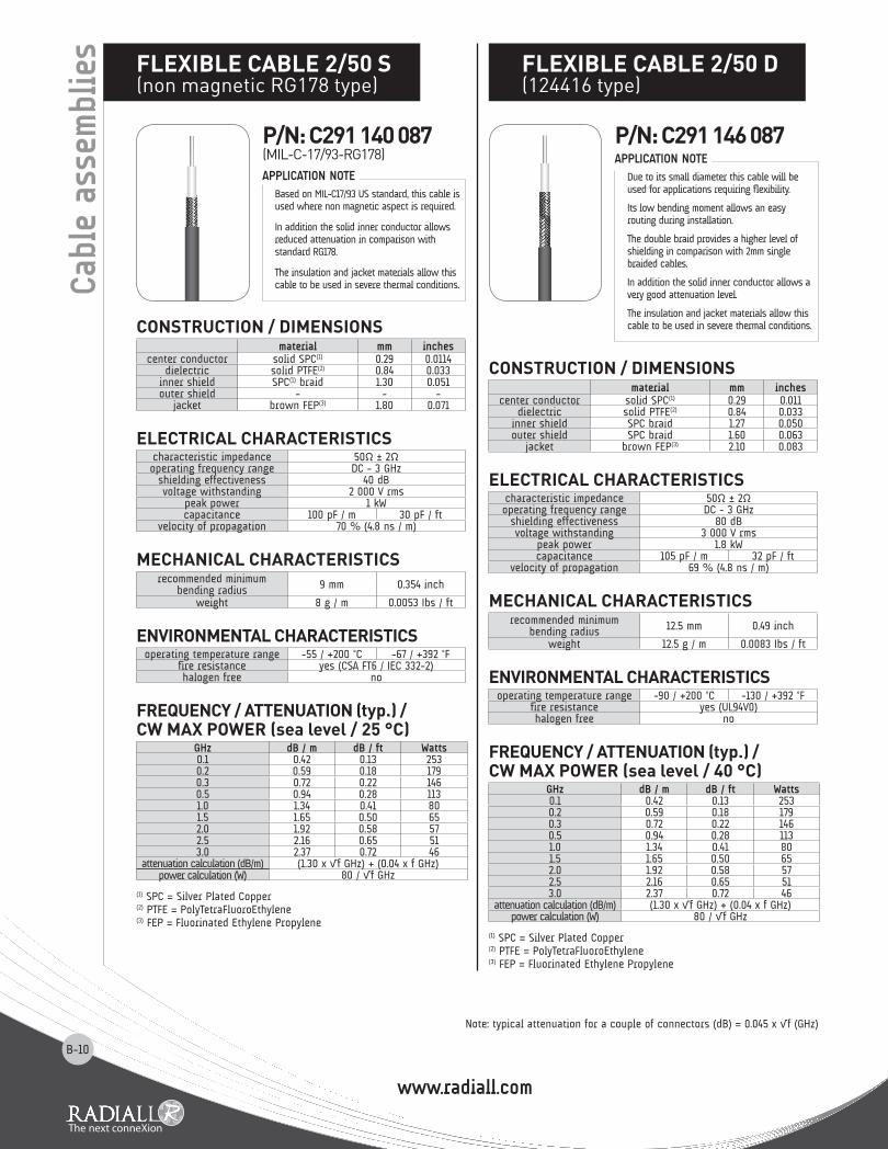
Due to its small diameter this cable will be used for applications requiring flexibility.
Its low bending moment allows an easy routing during installation.
The double braid provides a higher level of shielding in comparison with 2mm single braided cables.
In addition the solid inner conductor allows a very good attenuation level.
The insulation and jacket materials allow this cable to be used in severe thermal conditions.
APPLICATION NOTE
Cab
le a
ssem
blie
s flEXIblE CablE 2/50 D(124416 type)
p/N: C291 146 087
Note: typical attenuation for a couple of connectors (dB) = 0.045 x √f (GHz)
CONSTRUCTION / DImENSIONS material mm inches
center conductor solid SPC(1) 0.29 0.0114dielectric solid PTFE(2) 0.84 0.033
inner shield SPC(1) braid 1.30 0.051outer shield - - -
jacket brown FEP(3) 1.80 0.071
ElECTRICal ChaRaCTERISTICS characteristic impedance 50Ω ± 2Ωoperating frequency range DC - 3 GHz
shielding effectiveness 40 dBvoltage withstanding 2 000 V rms
peak power 1 kWcapacitance 100 pF / m 30 pF / ft
velocity of propagation 70 % (4.8 ns / m)
mEChaNICal ChaRaCTERISTICS recommended minimum
bending radius 9 mm 0.354 inch
weight 8 g / m 0.0053 Ibs / ft
ENVIRONmENTal ChaRaCTERISTICS operating temperature range -55 / +200 °C -67 / +392 °F
fire resistance yes (CSA FT6 / IEC 332-2)halogen free no
fREqUENCy / aTTENUaTION (typ.) / CW maX pOWER (sea level / 25 °C)
GHz dB / m dB / ft Watts0.1 0.42 0.13 2530.2 0.59 0.18 1790.3 0.72 0.22 1460.5 0.94 0.28 1131.0 1.34 0.41 801.5 1.65 0.50 652.0 1.92 0.58 572.5 2.16 0.65 513.0 2.37 0.72 46
attenuation calculation (dB/m) (1.30 x √f GHz) + (0.04 x f GHz)power calculation (W) 80 / √f GHz
(1) SPC = Silver Plated Copper(2) PTFE = PolyTetraFluoroEthylene(3) FEP = Fluorinated Ethylene Propylene
Based on MIL-C17/93 US standard, this cable is used where non magnetic aspect is required.
In addition the solid inner conductor allows reduced attenuation in comparison with standard RG178.
The insulation and jacket materials allow this cable to be used in severe thermal conditions.
APPLICATION NOTE
flEXIblE CablE 2/50 S(non magnetic RG178 type)
p/N: C291 140 087(MIL-C-17/93-RG178)

www.radiall.com
B-11
CONSTRUCTION / DImENSIONS material mm inches
center conductor solid SPCCS(1) 0.17 0.007dielectric solid PE(2) 1.00 0.039
inner shield SPC(3) braid 1.32 0.052outer shield - - -
jacket black LSZH PE(4) 1.90 0.075
ElECTRICal ChaRaCTERISTICS characteristic impedance 75Ω ± 5Ωoperating frequency range DC - 3 GHz
shielding effectiveness 50 dB minvoltage withstanding 8 000 V rms
peak power 400 Wcapacitance 67 pF / m 20.1 pF / ft
velocity of propagation 66 % (5 ns / m)
mEChaNICal ChaRaCTERISTICS recommended minimum
bending radius 10 mm 0.394 inch
weight 6.6 g / m 0.0044 lbs / ft
ENVIRONmENTal ChaRaCTERISTICS operating temperature range -60 / +85 °C -40 / +185 °F
fire resistance nohalogen free yes (IEC 754-2)
fREqUENCy / aTTENUaTION (typ. / 25 °C) / CW maX pOWER (sea level / 40 °C)
GHz dB / m dB / ft Watts0.1 0.42 0.13 410.2 0.60 0.18 290.3 0.74 0.22 230.4 0.86 0.26 200.6 1.06 0.32 161.0 1.38 0.42 121.5 1.70 0.52 102.0 1.98 0.60 82.5 2.23 0.68 73.0 2.46 0.75 6
attenuation calculation (dB/m) (1.317 x √f GHz) + (0.06 x f GHz)
(1) SPCCS = Silver Plated Copper covered steel(2) PE = PolyEthylene(3) SPC = Silver Plated Copper(4) LSZH PE = Low Smoke Zero Halogen PolyEthylene
CONSTRUCTION / DImENSIONS material mm inches
center conductor stranded CCS(1) 0.48 0.019dielectric solid PE(2) 1.52 0.060
inner shield TC(3) braid 2.21 0.087outer shield - - -
jacket black PVC(4) 2.79 0.110
ElECTRICal ChaRaCTERISTICS characteristic impedance 50Ω ± 2Ωoperating frequency range DC - 1 GHz
shielding effectiveness 40 dBvoltage withstanding 2 000 V rms
peak power 1.4 kWcapacitance 97.5 pF / m 29.5 pF / ft
velocity of propagation 66 % (5 ns / m)
mEChaNICal ChaRaCTERISTICS recommended minimum
bending radius 10 mm 0.394 inch
weight 13 g / m 0.0088 Ibs / ft
ENVIRONmENTal ChaRaCTERISTICS operating temperature range -40 / +85 °C -40 / +185 °F
fire resistance nohalogen free no
fREqUENCy / aTTENUaTION (typ.) / CW maX pOWER (sea level / 25 °C)
GHz dB / m dB / ft Watts0.05 0.23 0.07 720.1 0.33 0.10 510.2 0.47 0.14 360.3 0.58 0.17 290.5 0.75 0.23 230.6 0.82 0.25 210.7 0.89 0.27 190.8 0.95 0.29 181.0 1.07 0.32 16
attenuation calculation (dB/m) (1.03 x √f GHz) + (0.04 x f GHz)power calculation (W) 16 / √f GHz
(1) CCS = Copper Covered Steel(2) PE = PolyEthylene(3) TC = Tinned Copper(4) PVC = PolyVinyl Chloride
Due to its 75 ohms characteristic impedance, this cable is rather dedicated to TV/Video and networks application.Its small diameter and light weight make it perfect to be used in all miniature, space saving and dymamic applications. For cost effectiveness reasons and for low
frequency applications, RG174 may be used instead of RG316 when environmental conditions like operating temperature allow it.This cable is compatible with a large range of connector series.
APPLICATION NOTE
APPLICATION NOTE
flEXIblE CablE 2/75 S(296775 type)
flEXIblE CablE 2.6/50 S(RG174 - KX3B)
p/N: C291 147 060 p/N: C291 150 000(MIL-C-17/119-RG174)
p/N: C291 150 010(NF-C-93/550-KX3B)
: Service+ program = fast deliveryNote: typical attenuation for a couple of connectors (dB) = 0.045 x √f (GHz)
Cab
le a
ssem
blie
s
Cost effective solution

www.radiall.com
B-12
CONSTRUCTION / DImENSIONS material mm inches
center conductor stranded SPCCS(1) 0.53 0.021dielectric solid PTFE(2) 1.52 0.060
inner shield SPC(3) braid 1.98 0.078outer shield - - -
jacket brown FEP(4) 2.49 0.098
ElECTRICal ChaRaCTERISTICS characteristic impedance 50Ω ± 2Ωoperating frequency range DC - 3 GHz
shielding effectiveness 40 dBvoltage withstanding 2 000 V rms
peak power 1.8 kWcapacitance 96 pF / m 29 pF / ft
velocity of propagation 70 % (4.8 ns / m)
mEChaNICal ChaRaCTERISTICS recommended minimum
bending radius 10 mm 0.394 inch
weight 17 g / m 0.0110 Ibs / ft
ENVIRONmENTal ChaRaCTERISTICS operating temperature range -55 / +200 °C -67 / +392 °F
fire resistance yes (CSA FT6 / IEC 332-2)halogen free no
fREqUENCy / aTTENUaTION (typ.) / CW maX pOWER (sea level / 25 °C)
GHz dB / m dB / ft Watts0.1 0.26 0.08 4110.2 0.37 0.11 2910.3 0.46 0.14 2370.5 0.60 0.18 1841.0 0.86 0.26 1301.5 1.06 0.32 1062.0 1.24 0.38 922.5 1.40 0.42 823.0 1.54 0.47 75
attenuation calculation (dB/m) (0.82 x √f GHz) + (0.04 x f GHz)power calculation (W) 130 / √f GHz
(1) SPCCS = Silver Plated Copper covered steel(2) PTFE = PolyTetraFluoroEthylene(3) SPC = Silver Plated Copper(4) FEP = Fluorinated Ethylene Propylene
RG316 is one of the most popular RG cables.
This cable has a good flexibility and a better attenuation than RG174.
Usable in severe thermal conditions, this cable is compatible with a large range of connector series.
APPLICATION NOTE
Cab
le a
ssem
blie
s flEXIblE CablE 2.6/50 S(RG316 - KX22A)
p/N: C291 170 007(MIL-C-17/113-RG316)
p/N: C291 170 017(NF-C-93/550-KX22A)
: Service+ program = fast deliveryNote: typical attenuation for a couple of connectors (dB) = 0.045 x √f (GHz)
lOW lOSS flEXIblE CablE 2.6/50 S (ECO316: alternative to RG316)
p/N: C291 999 904
CONSTRUCTION / DImENSIONS material mm inches
center conductor solid OFC(1) 0.55 0.022dielectric foam PE(2) 1.55 0.061
inner shield OFC(1) braid 1.90 0.075outer shield - - -
jacket black LSZH PE(3) 2.45 0.096
ElECTRICal ChaRaCTERISTICS characteristic impedance 50Ω ± 2Ωoperating frequency range DC - 3 GHz
shielding effectiveness 50 dBvoltage withstanding 2 000 V rms
peak power 1.4 kWcapacitance 84 pF / m 25.5 pF / ft
velocity of propagation 80 % (4.15 ns / m)
mEChaNICal ChaRaCTERISTICS recommended minimum
bending radius 15 mm 0.590 inch
weight 10 g / m 0.0066 Ibs / ft
ENVIRONmENTal ChaRaCTERISTICS operating temperature range -40 / +85 °C -40 / +185 °F
fire resistance yes (UL1581 VW1 / IEC 332-1)halogen free yes (IEC 754-2)
fREqUENCy / aTTENUaTION (typ.) / CW maX pOWER (sea level / 25 °C)
GHz dB / m dB / ft Watts0.1 0.24 0.07 1200.2 0.33 0.10 850.3 0.41 0.12 690.5 0.53 0.16 541.0 0.76 0.23 381.5 0.94 0.28 312.0 1.09 0.33 272.5 1.22 0.37 243.0 1.34 0.41 22
attenuation calculation (dB/m) (0.74 x √f GHz) + (0.02 x f GHz)power calculation (W) 38 / √f GHz
(1) OFC = Oxygen Free Copper(2) PE = PolyEthylene(3) LSZH PE = Low Smoke Zero Halogen PolyEthylene
Designed by RADIALL, ECO316 is an advantageous alternative solution to RG316:• Advantageous in term of electrical performance: its optimized construction allows better attenuation and screening effectiveness than RG316 and RG 174.• Advantageous in term of environmental aspect: halogen and sulphur free, this cable does not emit any toxic substance when submitted to fire. The flame retardant jacket allows ECO316 to meet fire resistance standards.• Advantageous in term of price: ECO316 design has integrated all RADIALL knowledge to reach the best performances with a very competitive price.ECO316 is UL style 1375 approved.This cable is compatible with a large range of connector series.
ECO-Friendly cableCost effective solution
APPLICATION NOTE

www.radiall.com
B-13
CONSTRUCTION / DImENSIONS material mm inches
center conductor stranded SPC(1) 0.54 0.021dielectric X foam PE(2) 1.54 0.061
inner shield SPC(1) braid 2.05 0.081jacket blue LSZH PE(3) 2.52 0.099
ElECTRICal ChaRaCTERISTICS characteristic impedance 50Ω ± 2Ωoperating frequency range DC - 3 GHz
shielding effectiveness 35 dBvoltage withstanding 3 000 V rms
capacitance 94.5 pF / m 28.7 pF / ftvelocity of propagation 71 % (4.7 ns / m)
mEChaNICal ChaRaCTERISTICS recommended minimum
bending radius 5 mm 0.197 inch
weight 16 g / m 0.011 Ibs / ft
ENVIRONmENTal ChaRaCTERISTICS operating temperature range -40 / +105 °C -40 / +221 °F
fire resistance yes (UL1581 VW1 / IEC 332-1)halogen free yes (IEC 754-2)
fREqUENCy / aTTENUaTION (typ.) / CW maX pOWER (sea level / 20 °C)
GHz dB / m dB / ft Watts0.1 0.27 0.08 2850.3 0.49 0.15 1640.5 0.65 0.20 1270.6 0.72 0.22 1160.8 0.84 0.26 1011.0 0.96 0.29 901.5 1.22 0.37 732.0 1.45 0.44 642.5 1.66 0.50 573.0 1.85 0.56 52
attenuation calculation (dB/m) (0.81 x √f GHz) + (0.15 x f GHz)power calculation (W) 90 / √f GHz
(1) SPC = Silver Plated Copper(2) X foam PE = Crosslink foam PolyEthylene(3) LSZH PE = Low Smoke Zero Halogen PolyEthylene
Designed by RADIALL, ECO316X is an advantageous alternative solution to ECO316 when higher power level is required: • Advantageous in term of electrical performance: the crosslink foam polyethylene used as dielectric material allows higher temperature level (thus power range) than ECO316. • Advantageous in term of environmental aspect: halogen and sulphur free, this cable does not emit any toxic substance when submitted to fire. The flame retardant jacket allows ECO316X to meet fire resistance standards. • Advantageous in term of price: ECO316X design has integrated all RADIALL knowledge to reach the best performances with a very competitive price. ECO316X is UL style 1375 and 3651 approved This cable is compatible with a large range of standard connector series.
ECO-Friendly cableCost effective solution
APPLICATION NOTE
lOW lOSS flEXIblE CablE 2.6/50 S (ECO316X)
CONSTRUCTION / DImENSIONS material mm inches
center conductor stranded SPC(1) 0.53 0.021dielectric solid PTFE(2) 1.52 0.060
inner shield SPC(1) braid 1.90 0.075outer shield SPC(1) braid 2.30 0.091
jacket brown FEP(3) 2.80 0.110
ElECTRICal ChaRaCTERISTICS characteristic impedance 50Ω ± 2Ωoperating frequency range DC - 3 GHz
shielding effectiveness 60 dBvoltage withstanding 2 000 V rms
peak power 1.8 kWcapacitance 96 pF / m 29 pF / ft
velocity of propagation 70 % (4.8 ns / m)
mEChaNICal ChaRaCTERISTICS recommended minimum
bending radius 15 mm 0.590 inch
weight 27 g / m 0.0181 lbs / ft
ENVIRONmENTal ChaRaCTERISTICS operating temperature range -55 / +200 °C -67 / +392 °F
fire resistance yes (CSA FT6 / IEC 332-2)halogen free no
fREqUENCy / aTTENUaTION (typ.) / CW maX pOWER (sea level / 25 °C)
GHz dB / m dB / ft Watts0.1 0.26 0.08 4110.2 0.37 0.11 2910.3 0.46 0.14 2370.5 0.60 0.18 1841.0 0.86 0.26 1301.5 1.06 0.32 1062.0 1.24 0.38 922.5 1.40 0.42 823.0 1.54 0.47 75
attenuation calculation (dB/m) (0.82 x √f GHz) + (0.04 x f GHz)power calculation (W) 130 / √f GHz
(1) SPC = Silver Plated Copper(2) PTFE = PolyTetraFluoroEthylene(3) FEP = Fluorinated Ethylene Propylene
Based on the RG 316 construction, RD316 has an outer shield braid which allows higher screening effectiveness and better mechanical resistance.Usable in severe thermal conditions, this cable is compatible with a large range of connector series.
APPLICATION NOTE
flEXIblE CablE 2.6/50 D(RD316)
p/N: C291 185 067 p/N: C291 171 083
: Service+ program = fast deliveryNote: typical attenuation for a couple of connectors (dB) = 0.045 x √f (GHz)
Cab
le a
ssem
blie
s

www.radiall.com
B-14
lOW lOSS flEXIblE CablE 2.6/50 D (ECO316D: alternative to RD316)
CONSTRUCTION / DImENSIONS material mm inches
center conductor solid OFC(1) 0.55 0.022dielectric foam PE(2) 1.55 0.061
inner shield OFC(1) braid 1.90 0.075outer shield OFC(1) braid 2.30 0.091
jacket black LSZH PE(3) 2.80 0.110
ElECTRICal ChaRaCTERISTICS characteristic impedance 50Ω ± 2Ωoperating frequency range DC - 3 GHz
shielding effectiveness 65 dBvoltage withstanding 2 000 V rms
peak power 1.4 kWcapacitance 84 pF / m 25.5 pF / ft
velocity of propagation 80 % (4.15 ns / m)
mEChaNICal ChaRaCTERISTICS recommended minimum
bending radius 15 mm 0.590 inch
weight 16 g / m 0.0106 lbs / ft
ENVIRONmENTal ChaRaCTERISTICS operating temperature range -40 / +85 °C -40 / +185 °F
fire resistance yes (UL 1581 VW1 / IEC 332-1)halogen free yes (IEC 754-2)
fREqUENCy / aTTENUaTION (typ.) / CW maX pOWER (sea level / 25 °C)
GHz dB / m dB / ft Watts0.1 0.24 0.07 1200.2 0.33 0.10 850.3 0.41 0.12 690.5 0.53 0.16 541.0 0.76 0.23 381.5 0.94 0.28 312.0 1.09 0.33 272.5 1.22 0.37 243.0 1.34 0.41 22
attenuation calculation (dB/m) (0.74 x √f GHz) + (0.02 x f GHz)power calculation (W) 38 / √f GHz
(1) OFC = Oxygen Free Copper(2) PE = PolyEthylene
(3) LSZH PE = Low Smoke Zero Halogen PolyEthylene
Designed by RADIALL, ECO316D is an advantageous alternative solution to RD316:
• Advantageous in term of electrical performance: its optimized construction allows better attenuation and screening effectiveness than RD316.
• Advantageous in term of environmental aspect: halogen and sulphur free, this cable does not emit any toxic substance when submitted to fire. The flame retardant jacket allows ECO316D to meet fire resistance standards.
• Advantageous in term of price: ECO316D design has integrated all RADIALL knowledge to reach the best performances with a very competitive price. ECO316D is UL style 1375 approved.
This cable is compatible with a large range of connector series.
ECO-Friendly cableCost effective solution
APPLICATION NOTE
p/N: C291 999 905
Cab
le a
ssem
blie
s lOW lOSS flEXIblE CablE 2.6/50 D (ECO316DX)
CONSTRUCTION / DImENSIONS material mm inches
center conductor stranded SPC(1) 0.54 0.021dielectric X foam PE(2) 1.54 0.061
inner shield SPC(1) braid 2.03 0.080outer shield SPC(1) braid 2.50 0.098
jacket black with blue stripeLSZH PE(3) 3.16 0.124
ElECTRICal ChaRaCTERISTICS characteristic impedance 50Ω ± 2Ωoperating frequency range DC - 6 GHz
shielding effectiveness 70 dB (DC - 5 GHz)voltage withstanding 1 500 V rms
capacitance 94.5 pF / m 28.7 pF / ftvelocity of propagation 71 % (4.7 ns / m)
mEChaNICal ChaRaCTERISTICS recommended minimum
bending radius 5 mm 0.196 inch
weight 21 g / m 0.0140 Ibs / ft
ENVIRONmENTal ChaRaCTERISTICS operating temperature range -40 / +105 °C -40 / +221 °F
fire resistance yes (UL1581 VW1 / IEC 332-1)halogen free yes (IEC 754-2)
fREqUENCy / aTTENUaTION (typ.) / CW maX pOWER (sea level / 25 °C)
GHz dB / m dB / ft Watts0.5 0.58 0.17 1271.0 0.86 0.26 901.5 1.09 0.33 732.0 1.30 0.40 642.5 1.50 0.45 573.0 1.68 0.51 523.5 1.85 0.56 484.0 2.02 0.61 455.0 2.34 0.71 406.0 2.64 0.80 37
attenuation calculation (dB/m) (0.71 x √f GHz) + (0.15 x f GHz)power calculation (W) 90 / √f GHz
(1) SPC = Silver Plated Copper(2) X foam PE = Crosslink foam PolyEthylene(3) LSZH PE = Low Smoke Zero Halogen PolyEthylene
Designed by RADIALL, ECO316DX is an advantageous alternative solution to ECO316D when higher power level is required: • Advantageous in term of electrical performance: the crosslink foam polyethylene used as dielectric material allows higher temperature level (thus power range) than ECO316D. • Advantageous in term of environmental aspect: halogen and sulphur free, this cable does not emit any toxic substance when submitted to fire. The flame retardant jacket allows ECO316DX to meet fire resistance standards. • Advantageous in term of price: ECO316DX design has integrated all RADIALL knowledge to reach the best performances with a very competitive price. ECO316DX is UL style 1375 and 3651 approved. This cable is compatible with a large range of standard connector series.
ECO-Friendly cableCost effective solution
APPLICATION NOTE
p/N: C291 217 020
: Service+ program = fast deliveryNote: typical attenuation for a couple of connectors (dB) = 0.045 x √f (GHz)

www.radiall.com
B-15
Cab
le a
ssem
blie
s
CONSTRUCTION / DImENSIONS material mm inches
center conductor solid BC(1) 0.60 0.024dielectric foam PE(2) 2.80 0.110
inner shield Triplex tape Al(3)/PES(4)/Al 2.90 0.114outer shield TC(5) braid 3.30 0.130
jacket purple LSZH PE(6) 4.60 0.181
ElECTRICal ChaRaCTERISTICS characteristic impedance 75Ω ± 3Ωoperating frequency range DC - 3 GHz
shielding effectiveness -voltage withstanding 1 500 V rms
peak power -capacitance 56 pF / m 17.07 pF / ft
velocity of propagation 78 % (4.3 ns / m)
mEChaNICal ChaRaCTERISTICS recommended minimum
bending radius 37 mm 1.46 inch
weight 24 g / m 0.0161 lbs / ft
ENVIRONmENTal ChaRaCTERISTICS operating temperature range -20 / +70 °C -4 / +158 °F
fire resistance yes (IEC 60332-1)halogen free yes (IEC 60754-1 & -2)
fREqUENCy / aTTENUaTION (typ.) / CW maX pOWER (sea level / 25 °C)
GHz dB / m dB / ft Watts0.05 0.073 0.022 -0.1 0.103 0.031 -0.5 0.238 0.072 -0.8 0.305 0.092 -1.0 0.343 0.104 -1.5 0.426 0.129 -2.0 0.499 0.151 -2.5 0.563 0.171 -3.0 0.623 0.189 -
attenuation calculation (dB/m) (0.32 x √f GHz) + (0.023 x f GHz)
(1) BC = Bare Copper(2) PE = PolyEthylene(3) Al = Aluminum(4) PES = PolyESter(5) TC = Tinned Copper(6) LSZH PE = Low Smoke Zero Halogen PolyEthylene
Due to its 75 ohms characteristic impedance, this cable is rather dedicated to HDTV/Video application.
APPLICATION NOTE
flEXIblE CablE 4.6/75 D(HD 0.6/2.8 - mini RG59 type)
p/N: C291 333 039
CONSTRUCTION / DImENSIONS material mm inches
center conductor stranded SPCCS(1) 0.30 0.012dielectric solid PTFE(2) 1.60 0.063
inner shield SPC(3) braid 2.00 0.079outer shield - - -
jacket brown FEP(4) 2.54 0.100
ElECTRICal ChaRaCTERISTICS characteristic impedance 75Ω ± 3Ωoperating frequency range DC - 3 GHz
shielding effectiveness 40 dBvoltage withstanding 2 000 V rms
peak power 1.6 kWcapacitance 69 pF / m 21 pF / ft
velocity of propagation 70 % (4.8 ns / m)
mEChaNICal ChaRaCTERISTICS recommended minimum
bending radius 10 mm 0.400 inch
weight 14.5 g / m 0.0097 lbs / ft
ENVIRONmENTal ChaRaCTERISTICS operating temperature range -55 / +200 °C -67 / +392 °F
fire resistance yes (CSA FT6 / IEC 332-2)halogen free no
fREqUENCy / aTTENUaTION (typ.) / CW maX pOWER (sea level / 25 °C)
GHz dB / m dB / ft Watts0.1 0.29 0.09 7910.2 0.41 0.13 5590.3 0.51 0.15 4560.5 0.66 0.20 3541.0 0.95 0.29 2501.5 1.17 0.36 2042.0 1.37 0.41 1172.5 1.54 0.47 1583.0 1.70 0.51 144
attenuation calculation (dB/m) (0.91 x √f GHz) + (0.04 x f GHz)power calculation (W) 250 / √f GHz
(1) SPCCS = Silver Plated Copper Covered Steel(2) PTFE = PolyTetraFluoroEthylene(3) SPC = Silver Plated Copper(4) FEP = Fluorinated Ethylene Propylene
Due to its 75 ohms characteristic impedance, RG179 is rather dedicated to TV/Video application.
Its small internal stranded inner conductor diameter allows high flexibility for an easy routing.
Usable in severe thermal conditions.
APPLICATION NOTE
flEXIblE CablE 2.6/75 S(RG179)
p/N: C291 210 007 (MIL-C-17/94-RG179)
: Service+ program = fast deliveryNote: typical attenuation for a couple of connectors (dB) = 0.045 x √f (GHz)
www.radiall.com
B-16
CONSTRUCTION / DImENSIONS material mm inches
center conductor stranded TC(1) 0.90 0.035dielectric solid PE(2) 2.95 0.116
inner shield TC(1) braid 3.66 0.144outer shield - - -
jacket black PVC(3) 4.95 0.195
ElECTRICal ChaRaCTERISTICS characteristic impedance 50Ω ± 2Ωoperating frequency range DC - 1 GHz
shielding effectiveness 40 dBvoltage withstanding 5 000 V rms
peak power 2.6 kWcapacitance 96 pF / m 29 pF / ft
velocity of propagation 66 % (5 ns / m)
mEChaNICal ChaRaCTERISTICS recommended minimum
bending radius 20 mm 0.787 inch
weight 35 g / m 0.0234 Ibs / ft
ENVIRONmENTal ChaRaCTERISTICS operating temperature range -40 / +85 °C -40 / +185 °F
fire resistance nohalogen free no
fREqUENCy / aTTENUaTION (typ.) / CW maX pOWER (sea level / 25 °C)
GHz dB / m dB / ft Watts0.05 0.14 0.04 2460.1 0.20 0.06 1740.2 0.29 0.09 1230.3 0.36 0.11 1000.5 0.47 0.14 780.6 0.51 0.16 710.7 0.56 0.17 660.8 0.60 0.18 611.0 0.67 0.20 55
attenuation calculation (dB/m) (0.63 x √f GHz) + (0.04 x f GHz)power calculation (W) 55 / √f GHz
(1) TC = Tinned Copper(2) PE = PolyEthylene(3) PVC = PolyVinyl Chloride
CONSTRUCTION / DImENSIONS material mm inches
center conductor solid SPCCS(1) 0.94 0.037dielectric solid PTFE(2) 2.95 0.116
inner shield SPC(3) braid - -outer shield SPC(3) braid 4.19 0.165
jacket brown FEP(4) 4.95 0.195
ElECTRICal ChaRaCTERISTICS characteristic impedance 50Ω ± 2Ωoperating frequency range DC - 12.4 GHz
shielding effectiveness 65 dB (DC - 3GHz)voltage withstanding 5 000 V rms
peak power 3.4 kWcapacitance 97 pF / m 29.3 pF / ft
velocity of propagation 70 % (4.8 ns / m)
mEChaNICal ChaRaCTERISTICS recommended minimum
bending radius 25 mm 0.984 inch
weight 64 g / m 0.043 Ibs / ft
ENVIRONmENTal ChaRaCTERISTICS operating temperature range -55 / +200 °C -67 / +392 °F
fire resistance yes (CSA FT6 / IEC 332-2)halogen free no
fREqUENCy / aTTENUaTION (typ.) / CW maX pOWER (sea level / 25 °C)
GHz dB / m dB / ft Watts0.5 0.30 0.09 6651.0 0.44 0.13 4701.5 0.55 0.17 3842.0 0.65 0.20 3323.0 0.81 0.25 2716.0 1.22 0.37 1928.0 1.45 0.44 16610.0 1.66 0.50 14912.4 1.90 0.58 133
attenuation calculation (dB/m) (0.40 x √f GHz) + (0.04 x f GHz)power calculation (W) 470 / √f GHz
(1) SPCCS = Silver Plated Copper Covered Steel(2) PTFE = PolyTetraFluoroEthylene(3) SPC = Silver Plated Copper(4) FEP = Fluorinated Ethylene Propylene
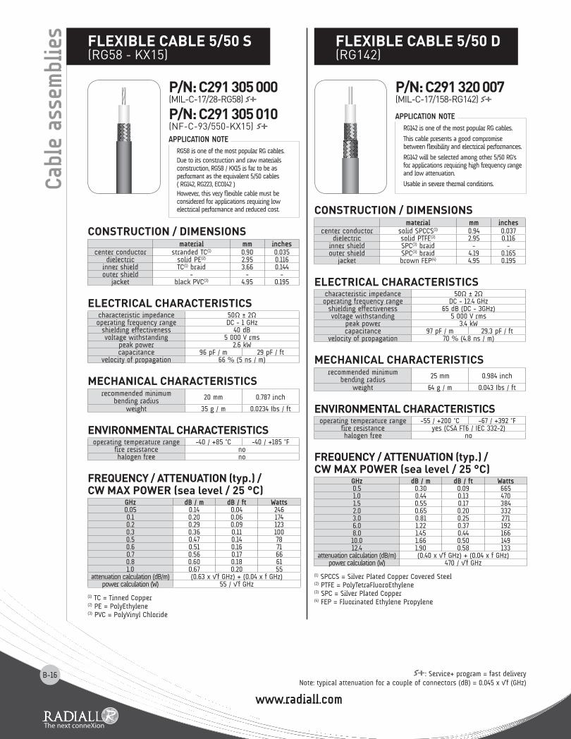
RG142 is one of the most popular RG cables.
This cable presents a good compromise between flexibility and electrical performances.
RG142 will be selected among other 5/50 RG's for applications requiring high frequency range and low attenuation.
Usable in severe thermal conditions.
RG58 is one of the most popular RG cables.Due to its construction and raw materials construction, RG58 / KX15 is far to be as performant as the equivalent 5/50 cables ( RG142, RG223, ECO142 )However, this very flexible cable must be considered for applications requiring low electrical performance and reduced cost.
APPLICATION NOTE
APPLICATION NOTE
Cab
le a
ssem
blie
s flEXIblE CablE 5/50 S(RG58 - KX15)
flEXIblE CablE 5/50 D(RG142)
p/N: C291 320 007(MIL-C-17/158-RG142)
p/N: C291 305 000(MIL-C-17/28-RG58)
p/N: C291 305 010(NF-C-93/550-KX15)
: Service+ program = fast deliveryNote: typical attenuation for a couple of connectors (dB) = 0.045 x √f (GHz)

www.radiall.com
B-17: Service+ program = fast deliveryNote: typical attenuation for a couple of connectors (dB) = 0.045 x √f (GHz)
Cab
le a
ssem
blie
slOW lOSS flEXIblE CablE 5/50 D (ECO142: alternative to RG142)
CONSTRUCTION / DImENSIONS material mm inches
center conductor solid OFC(1) copper 0.95 0.037dielectric foam PE(2) 2.85 0.112
inner shield Al(3) foil 3.10 0.122outer shield TC(4) braid 3.50 0.138
jacket black LSZH PE(5) 4.50 0.177
ElECTRICal ChaRaCTERISTICS characteristic impedance 50Ω ± 2Ωoperating frequency range DC - 3 GHz
shielding effectiveness 80 dB (DC - 3 GHz)voltage withstanding 5 000 V rms
peak power 2.7 kWcapacitance 87 pF / m 26.4 pF / ft
velocity of propagation 77 % (4.3 ns / m)
mEChaNICal ChaRaCTERISTICS recommended minimum
bending radius 15 mm 0.590 inch
weight 36 g / m 0.0242 lbs / ft
ENVIRONmENTal ChaRaCTERISTICS operating temperature range -40 / +85 °C -40 / +185 °F
fire resistance yes (UL1581 VW1 / IEC 332-1)halogen free yes (IEC 754-2)
fREqUENCy / aTTENUaTION (typ.) / CW maX pOWER (sea level / 25 °C)
GHz dB / m dB / ft Watts0.1 0.12 0.04 4110.2 0.18 0.05 2910.3 0.22 0.07 2370.5 0.28 0.09 1841.0 0.41 0.12 1301.5 0.50 0.15 1062.0 0.58 0.18 922.5 0.66 0.20 823.0 0.73 0.22 75
attenuation calculation (dB/m) (0.385 x √f GHz) + (0.02 x f GHz)power calculation (W) 130 / √f GHz
(1) OFC = Oxygen Free Copper(2) PE = PolyEthylene(3) Al = Aluminum(4) TC = Tinned Copper(5) LSZH PE = Low Smoke Zero Halogen PolyEthylene
Designed by RADIALL, ECO142 is an advantageous alternative solution to RG142:
• Advantageous in term of electrical performance: its optimized construction allows better attenuation and screening effectiveness than RG142.
• Advantageous in term of environmental aspect: halogen and sulphur free, this cable does not emit any toxic substance when submitted to fire. The flame retardant jacket allows ECO142 to meet fire resistance standards.
• Advantageous in term of price: ECO142 design has integrated all RADIALL knowledge to reach the best performances with a very competitive price. ECO142 is UL style 1375 approved.
This cable is compatible with a large range of connector series.
ECO-Friendly cableCost effective solution
APPLICATION NOTE
p/N: C291 325 290
lOW lOSS flEXIblE CablE 5/50 D (ECO142X)
CONSTRUCTION / DImENSIONS material mm inches
center conductor solid SPC(1) 0.95 0.037dielectric X foam PE(2) 2.98 0.117
inner shield SPC(1) braid 3.64 0.143outer shield SPC(1) braid 4.30 0.169
jacket black with blue stripeLSZH PE(3) 5.00 0.197
ElECTRICal ChaRaCTERISTICS characteristic impedance 50Ω ± 2Ωoperating frequency range DC - 6 GHz
shielding effectiveness 75 dB (DC - 5 GHz)voltage withstanding 5 000 V rms
capacitance 94.5 pF / m 28.7 pF / ftvelocity of propagation 71 % (4.7 ns / m)
mEChaNICal ChaRaCTERISTICS recommended minimum
bending radius 30 mm 1.18 inch
weight 60 g / m 0.0433 Ibs / ft
ENVIRONmENTal ChaRaCTERISTICS operating temperature range -40 / +105 °C -40 / +221 °F
fire resistance yes (UL1581 VW1 / IEC 332-1)halogen free yes (IEC 754-2)
fREqUENCy / aTTENUaTION (typ.) / CW maX pOWER (sea level / 25 °C)
GHz dB / m dB / ft Watts0.5 0.36 0.11 3541.0 0.54 0.16 2501.5 0.69 0.21 2042.0 0.83 0.25 1772.5 0.95 0.29 1583.0 1.07 0.32 1443.5 1.18 0.36 1344.0 1.29 0.39 1255.0 1.50 0.45 1126.0 1.70 0.51 102
attenuation calculation (dB/m) (0.44 x √f GHz) + (0.103 x f GHz)power calculation (W) 250 / √f GHz
(1) SPC = Silver Plated Copper(2) X foam PE = Crosslink foam PolyEthylene(3) LSZH PE = Low Smoke Zero Halogen PolyEthylene
Designed by RADIALL, ECO142X is an advantageous alternative solution to ECO142 when higher power level is required: • Advantageous in term of electrical performance: the crosslink foam polyethylene used as dielectric material allows higher temperature level (thus power range) than ECO142. • Advantageous in term of environmental aspect: halogen and sulphur free, this cable does not emit any toxic substance when submitted to fire. The flame retardant jacket allows ECO142X to meet fire resistance standards. • Advantageous in term of price: ECO142X design has integrated all RADIALL knowledge to reach the best performances with a very competitive price. ECO142X is UL style 1375 and 3651 approved. This cable is compatible with a large range of standard connector series.
ECO-Friendly cableCost effective solution
APPLICATION NOTE
p/N: C291 320 180

www.radiall.com
B-18
Cab
le a
ssem
blie
s lOW lOSS flEXIblE CablE 5/50 D (POWER142: alternative to RG142)
p/N: C291 325 270
CONSTRUCTION / DImENSIONS material mm inches
center conductor solid SPC(1) 0.92 0.036dielectric solid PTFE(2) 2.97 0.117
inner shield Al(3) foil 3.20 0.126outer shield TC(4) braid 3.60 0.142
jacket black LSZH PE(5) 4.50 0.177
ElECTRICal ChaRaCTERISTICS characteristic impedance 50Ω ± 2Ωoperating frequency range DC - 3 GHz
shielding effectiveness 90 dB (DC - 3 GHz)voltage withstanding 5 000 V rms
peak power 3.4 kWcapacitance 97 pF / m 29.3 pF / ft
velocity of propagation 69 % (4.8 ns / m)
mEChaNICal ChaRaCTERISTICS recommended minimum
bending radius 25 mm 0.980 inch
weight 40 g / m 0.0269 lbs / ft
ENVIRONmENTal ChaRaCTERISTICS operating temperature range -40 / +105 °C -40 / +221 °F
fire resistance yes (UL1581 VW1 / IEC 332-1)halogen free no
fREqUENCy / aTTENUaTION (typ.) / CW maX pOWER (sea level / 40 °C)
GHz dB / m dB / ft Watts0.2 0.18 0.05 4700.4 0.26 0.08 3320.6 0.32 0.10 2710.8 0.37 0.11 2351.0 0.41 0.12 2101.5 0.50 0.15 1712.0 0.58 0.18 1482.5 0.66 0.20 1333.0 0.72 0.22 121
attenuation calculation (dB/m) (0.402 x √f GHz) + (0.008 x f GHz)power calculation (W) 210 / √f GHz
(1) SPC = Silver Plated Copper(2) PTFE = PolyTetraFluoroEthylene
(3) Al = Aluminum(4) TC = Tinned Copper
(5) LSZH PE = Low Smoke Zero Halogen PolyEthylene
Designed by RADIALL, POWER142 is an advantageous alternative solution to ECO142 when high power level is required:
• Advantageous in term of electrical performance: its optimized construction allows better attenuation and screening effectiveness than RG142 and higher power level than ECO142.
• Advantageous in term of environmental aspect: the flame retardant jacket allows POWER142 to meet fire resistance standards.
• Advantageous in term of price: POWER142 design has integrated all RADIALL knowledge to reach the best performances with a very competitive price. POWER142 is UL style 1375 approved.
This cable is compatible with a large range of connector series.
APPLICATION NOTE
CONSTRUCTION / DImENSIONS material mm inches
center conductor solid SPC(1) 0.89 0.035dielectric solid PE(2) 2.95 0.116
inner shield SPC(1) braid - -outer shield SPC(1) braid 4.19 0.165
jacket black PVC(3) 5.38 0.212
ElECTRICal ChaRaCTERISTICS characteristic impedance 50Ω ± 2Ωoperating frequency range DC - 12.4 GHz
shielding effectiveness 65 dB (DC - 3 GHz)voltage withstanding 5 000 V rms
peak power 2.6 kWcapacitance 96 pF / m 29 pF / ft
velocity of propagation 66 % (5 ns / m)
mEChaNICal ChaRaCTERISTICS recommended minimum
bending radius 25 mm 0.984 inch
weight 55 g / m 0.0370 lbs / ft
ENVIRONmENTal ChaRaCTERISTICS operating temperature range -40 / +85 °C -40 / +185 °F
fire resistance nohalogen free no
fREqUENCy / aTTENUaTION (typ.) / CW maX pOWER (sea level / 25 °C)
GHz dB / m dB / ft Watts0.5 0.32 0.10 711.0 0.46 0.14 501.5 0.57 0.17 412.0 0.67 0.20 353.0 0.85 0.26 296.0 1.27 0.38 208.0 1.51 0.46 1810.0 1.73 0.52 1612.4 1.97 0.60 14
attenuation calculation (dB/m) (0.42 x √f GHz) + (0.04 x f GHz)power calculation (W) 50 / √f GHz
(1) SPC = Silver Plated Copper(2) PE = PolyEthylene(3) PVC = PolyVinyl Chloride
RG223 is one of the most popular RG cables.
This cable presents a good compromise between flexibility and electrical performances.
RG223 can be used instead of RG142 for cost reasons in applications that do not require high temperature resistance.
APPLICATION NOTE
flEXIblE CablE 5/50 D (RG223)
p/N: C291 330 000(MIL-C-17/84-RG223)
: Service+ program = fast deliveryNote: typical attenuation for a couple of connectors (dB) = 0.045 x √f (GHz)
www.radiall.com
B-19
CONSTRUCTION / DImENSIONS material mm inches
center conductor stranded SPC(1) 0.98 0.039dielectric solid PTFE(2) 2.95 0.116
inner shield SPC(1) braid - -outer shield SPC(1) braid 4.19 0.165
jacket brown FEP(3) 4.95 0.195
ElECTRICal ChaRaCTERISTICS characteristic impedance 50Ω ± 2Ωoperating frequency range DC - 12.4 GHz
shielding effectiveness 65 dB (DC - 3 GHz)voltage withstanding 5 000 V rms
peak power 3.4 kWcapacitance 97 pF / m 29.3 pF / ft
velocity of propagation 70 % (4.8 ns / m)
mEChaNICal ChaRaCTERISTICS recommended minimum
bending radius 20 mm 0.79 inch
weight 66 g / m 0.0442 lbs / ft
ENVIRONmENTal ChaRaCTERISTICS operating temperature range -55 / +200 °C -67 / +392 °F
fire resistance yes (CSA FT6 / IEC 332-2)halogen free no
fREqUENCy / aTTENUaTION (typ.) / CW maX pOWER (sea level / 25 °C)
GHz dB / m dB / ft Watts0.5 0.36 0.11 6651.0 0.52 0.16 4701.5 0.65 0.20 3842.0 0.76 0.23 3323.0 0.95 0.29 2716.0 1.42 0.43 1928.0 1.68 0.51 16610.0 1.92 0.58 14912.4 2.19 0.66 133
attenuation calculation (dB/m) (0.48 x √f GHz) + (0.04 x f GHz)power calculation (W) 470 / √f GHz
(1) SPC = Silver Plated Copper(2) PTFE = PolyTetraFluoroEthylene(3) FEP = Fluorinated Ethylene Propylene
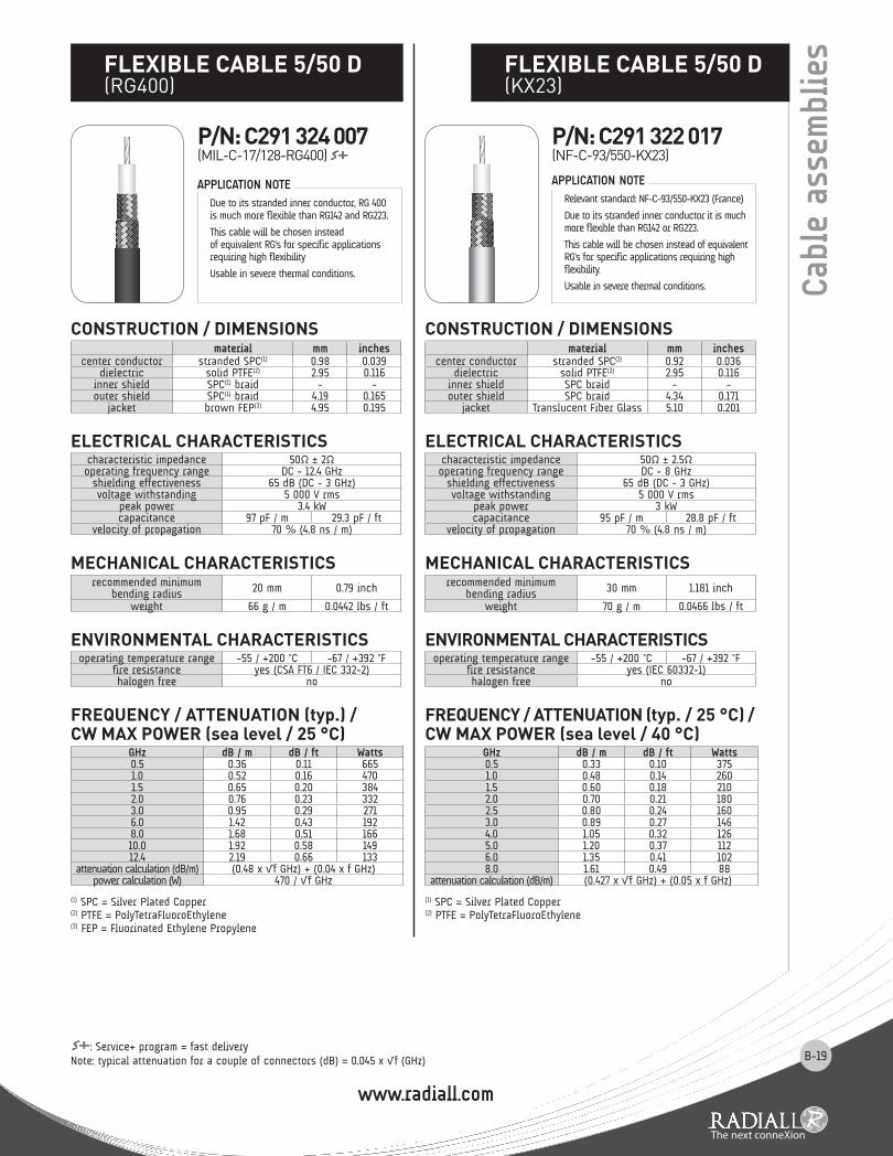
Due to its stranded inner conductor, RG 400 is much more flexible than RG142 and RG223.
This cable will be chosen instead of equivalent RG's for specific applications requiring high flexibility
Usable in severe thermal conditions.
APPLICATION NOTE
flEXIblE CablE 5/50 D (RG400)
p/N: C291 324 007(MIL-C-17/128-RG400)
CONSTRUCTION / DImENSIONS material mm inches
center conductor stranded SPC(1) 0.92 0.036dielectric solid PTFE(2) 2.95 0.116
inner shield SPC braid - -outer shield SPC braid 4.34 0.171
jacket Translucent Fiber Glass 5.10 0.201
ElECTRICal ChaRaCTERISTICS characteristic impedance 50Ω ± 2.5Ωoperating frequency range DC - 8 GHz
shielding effectiveness 65 dB (DC - 3 GHz)voltage withstanding 5 000 V rms
peak power 3 kWcapacitance 95 pF / m 28.8 pF / ft
velocity of propagation 70 % (4.8 ns / m)
mEChaNICal ChaRaCTERISTICS recommended minimum
bending radius 30 mm 1.181 inch
weight 70 g / m 0.0466 lbs / ft
ENVIRONmENTal ChaRaCTERISTICS operating temperature range -55 / +200 °C -67 / +392 °F
fire resistance yes (IEC 60332-1)halogen free no
fREqUENCy / aTTENUaTION (typ. / 25 °C) / CW maX pOWER (sea level / 40 °C)
GHz dB / m dB / ft Watts0.5 0.33 0.10 3751.0 0.48 0.14 2601.5 0.60 0.18 2102.0 0.70 0.21 1802.5 0.80 0.24 1603.0 0.89 0.27 1464.0 1.05 0.32 1265.0 1.20 0.37 1126.0 1.35 0.41 1028.0 1.61 0.49 88
attenuation calculation (dB/m) (0.427 x √f GHz) + (0.05 x f GHz)
(1) SPC = Silver Plated Copper(2) PTFE = PolyTetraFluoroEthylene
Relevant standard: NF-C-93/550-KX23 (France)
Due to its stranded inner conductor it is much more flexible than RG142 or RG223.
This cable will be chosen instead of equivalent RG's for specific applications requiring high flexibility.
Usable in severe thermal conditions.
APPLICATION NOTE
flEXIblE CablE 5/50 D(KX23)
p/N: C291 322 017(NF-C-93/550-KX23)
Cab
le a
ssem
blie
s
: Service+ program = fast deliveryNote: typical attenuation for a couple of connectors (dB) = 0.045 x √f (GHz)

www.radiall.com
B-20
Cab
le a
ssem
blie
s lOW lOSS flEXIblE CablE 6/50 D (ECO230)
p/N: C291 326 490
Note: typical attenuation for a couple of connectors (dB) = 0.045 x √f (GHz)
CONSTRUCTION / DImENSIONS material mm inches
center conductor OFC(1) copper 1.46 0.057dielectric foam PE(2) 4.07 0.160
inner shield Al(3) foil 4.27 0.168outer shield TC(4) braid 4.75 0.187
jacket black LSZH(5) PE 5.90 0.232
ElECTRICal ChaRaCTERISTICS characteristic impedance 50Ω ± 2Ωoperating frequency range DC - 4 GHz
shielding effectiveness 90 dB (DC - 3 GHz)voltage withstanding 3 000 V rms
peak power 3.3 kWcapacitance 84 pF / m 25.5 pF / ft
velocity of propagation 79 % (4.2 ns / m)
mEChaNICal ChaRaCTERISTICS recommended minimum
bending radius 25 mm 0.98 inch
weight 62 g / m 0.0417 lbs / ft
ENVIRONmENTal ChaRaCTERISTICS operating temperature range -40 / +85 °C -40 / +185 °F
fire resistance yes (UL1581 VW1 / IEC 332-1)halogen free yes (IEC 754-2)
fREqUENCy / aTTENUaTION (typ.) / CW maX pOWER (sea level / 40 °C)
GHz dB / m dB / ft Watts0.2 0.12 0.04 3910.4 0.17 0.05 2770.6 0.21 0.06 2260.8 0.25 0.08 1961.0 0.28 0.08 1751.5 0.35 0.10 1432.0 0.40 0.12 1242.5 0.45 0.14 1113.0 0.50 0.15 1014.0 0.59 0.18 88
attenuation calculation (dB/m) (0.264 x √f GHz) + (0.015 x f GHz)power calculation (W) 175 / √f GHz
(1) OFC = Oxygen Free Copper(2) PE = PolyEthylene(3) Al = Aluminum(4) TC = Tinned Copper(5) LSZH PE = Low Smoke Zero Halogen PolyEthylene
Designed by RADIALL, ECO230 is an advantageous alternative solution to 5 mm dia. cables when higher power level is required:
• Advantageous in term of electrical performance: its optimized construction allows better attenuation and screening effectiveness than RG cables.
• Advantageous in term of environmental aspect: halogen and sulphur free, this cable does not emit any toxic substance when submitted to fire. The flame retardant jacket allows ECO230 to meet fire resistance standards.
• Advantageous in term of price: ECO230 design has integrated all RADIALL knowledge to reach the best performances with a very competitive price.
ECO230 is UL style 1375 approved.
APPLICATION NOTE
CONSTRUCTION / DImENSIONS material mm inches
center conductor solid copper 1.12 0.044dielectric foam PE(1) 2.95 0.116
inner shield Al(2) foil 3.07 0.121outer shield TC(3) braid 3.66 0.144
jacket black PE(1) 4.95 0.195
ElECTRICal ChaRaCTERISTICS characteristic impedance 50Ω ± 2Ω
cut-off frequency 39 GHzrecommend. operat. freq. range DC - 6 GHz
shielding effectiveness > 90 dBvoltage withstanding 1 000 V DC
peak power 2.5 kWcapacitance 80.3 pF / m 24.5 pF / ft
velocity of propagation 83 % (4.0 ns / m)
mEChaNICal ChaRaCTERISTICS recommended minimum
bending radius 12.7 mm 0.50 inch
weight 30 g / m 0.022 lbs / ft
ENVIRONmENTal ChaRaCTERISTICS operating temperature range -40 / +85 °C -40 / +185 °F
fire resistance nohalogen free no
fREqUENCy / aTTENUaTION (typ.) / CW Typ pOWER (sea level / 40 °C)
GHz dB / m dB / ft Watts0.1 0.11 0.03 5600.5 0.24 0.07 2401.0 0.34 0.10 1701.5 0.42 0.13 1402.0 0.49 0.15 1202.5 0.55 0.17 1103.0 0.61 0.18 1004.0 0.71 0.22 805.0 0.80 0.24 706.0 0.88 0.27 65
attenuation calculation (dB/m) (0.333 x √f GHz) + (0.011 x f GHz)
(1) PE = PolyEthylene(2) Al = Aluminum
(3) TC = Tinned Copper
This LMR200 type cable can be considered as an alternative to equivalent diameter corrugated cables.The main advantage is greater flexibility and bendability allowing easy routing during the installation.The foam dielectric provides excellent loss and low return loss levels.The double screen construction (Aluminum foil + tinned copper braid) offers a high level of shielding as well as low leakage.This cable will be advised for feeder and jumper assemblies in cellular networks as well as applications requiring easy routing.
APPLICATION NOTE
lOW lOSS flEXIblE CablE 5/50 D (LMR200 type)
p/N: C291 316 070
www.radiall.com
B-21: Service+ program = fast deliveryNote: typical attenuation for a couple of connectors (dB) = 0.045 x √f (GHz)
Cab
le a
ssem
blie
s
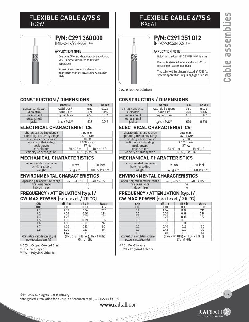
Due to its 75 ohms characteristic impedance, RG59 is rather dedicated to TV/Video application.
Its solid inner conductor allows better attenuation than the equivalent KX solution (KX6).
APPLICATION NOTE
flEXIblE CablE 6/75 S (RG59)
CONSTRUCTION / DImENSIONS material mm inches
center conductor solid CCS(1) 0.57 0.022dielectric solid PE(2) 3.71 0.146
inner shield copper braid 4.50 0.177outer shield - - -
jacket black PVC(3) 6.15 0.242
ElECTRICal ChaRaCTERISTICS characteristic impedance 75Ω ± 3Ωoperating frequency range DC - 1 GHz
shielding effectiveness 40 dBvoltage withstanding 7 000 V rms
peak power 2.7 kWcapacitance 60 pF / m 18.2 pF / ft
velocity of propagation 66 % (5 ns / m)
mEChaNICal ChaRaCTERISTICS recommended minimum
bending radius 30 mm 1.18 inch
weight 47 g / m 0.0315 lbs / ft
ENVIRONmENTal ChaRaCTERISTICS operating temperature range -40 / +85 °C -40 / +185 °F
fire resistance nohalogen free no
fREqUENCy / aTTENUaTION (typ.) / CW maX pOWER (sea level / 25 °C)
GHz dB / m dB / ft Watts0.05 0.09 0.03 3350.1 0.13 0.04 2370.2 0.19 0.06 1680.3 0.23 0.07 1370.5 0.30 0.09 1060.6 0.33 0.10 970.7 0.36 0.11 900.8 0.39 0.12 841.0 0.44 0.13 75
attenuation calculation (dB/m) (0.40 x √f GHz) + (0.04 x f GHz)power calculation (W) 75 / √f GHz
(1) CCS = Copper Covered Steel(2) PE = PolyEthylene(3) PVC = PolyVinyl Chloride
p/N: C291 360 000(MIL-C-17/29-RG59)
Relevant standard: NF-C-93/550-KX6 (France)
Due to its stranded inner conductor, KX6 is much more flexible than RG59.
This cable will be chosen instead of RG59 for specific applications requiring high flexibility.
APPLICATION NOTE
flEXIblE CablE 6/75 S (KX6A)
CONSTRUCTION / DImENSIONS material mm inches
center conductor stranded copper 0.60 0.024dielectric solid PE(1) 3.70 0.146
inner shield copper braid 4.50 0.177outer shield - - -
jacket green PVC(2) 6.10 0.240
ElECTRICal ChaRaCTERISTICS characteristic impedance 75Ω ± 3Ωoperating frequency range DC - 1 GHz
shielding effectiveness 40 dBvoltage withstanding 7 000 V rms
peak power 2.7 kWcapacitance 63 pF / m 19 pF / ft
velocity of propagation 66 % (5 ns / m)
mEChaNICal ChaRaCTERISTICS recommended minimum
bending radius 25 mm 0.98 inch
weight 48 g / m 0.0320 lbs / ft
ENVIRONmENTal ChaRaCTERISTICS operating temperature range -40 / +85 °C -40 / +185 °F
fire resistance nohalogen free no
fREqUENCy / aTTENUaTION (typ.) / CW maX pOWER (sea level / 25 °C)
GHz dB / m dB / ft Watts0.05 0.10 0.03 3000.1 0.14 0.04 2120.2 0.20 0.06 1500.3 0.25 0.08 1220.5 0.33 0.10 950.6 0.36 0.11 860.7 0.40 0.12 800.8 0.43 0.13 751.0 0.48 0.15 67
attenuation calculation (dB/m) (0.44 x √f GHz) + (0.04 x f GHz)power calculation (W) 67 / √f GHz
(1) PE = PolyEthylene(2) PVC = PolyVinyl Chloride
Cost effective solution
p/N: C291 351 012(NF-C-93/550-KX6)

www.radiall.com
B-22
CONSTRUCTION / DImENSIONS material mm inches
center conductor solid BC(1) 0.81 0.032dielectric FHD PE(2) 3.68 0.145
inner shield Al(3) tape 3.81 0.150outer shield TC(4) braid 4.37 0.172
jacket blue PVC(5) 5.92 0.233
ElECTRICal ChaRaCTERISTICS characteristic impedance 75Ω ± 1.5Ωoperating frequency range DC - 4.5 GHz
shielding effectiveness -voltage withstanding 300 V rms
peak power -capacitance 53.5 pF / m 16.3 pF / ft
velocity of propagation 83 % (4.0 ns / m)
mEChaNICal ChaRaCTERISTICS recommended minimum
bending radius 63.5 mm 2.5 inch
weight 46 g / m 0.031 lbs / ft
ENVIRONmENTal ChaRaCTERISTICS operating temperature range -30 / +75 °C -22 / +167 °F
fire resistance yes (UL1666 Vertical Shaft)halogen free no
fREqUENCy / aTTENUaTION (typ.) / CW maX pOWER (sea level / 25 °C)
GHz dB / m dB / ft Watts0.5 0.173 0.052 -1.0 0.247 0.075 -1.5 0.304 0.092 -2.0 0.353 0.107 -2.5 0.397 0.120 -3.0 0.437 0.132 -3.5 0.473 0.143 -4.0 0.508 0.154 -4.5 0.541 0.164 -
attenuation calculation (dB/m) (0.24 x √f GHz) + (0.007 x f GHz)
(1) BC = Bare Copper(2) FHD PE = Foam High Density PolyEthylene(3) Al = Aluminum(4) TC = Tinned Copper(5) PVC = PolyVinyl Chloride
Due to its 75 ohms characteristic impedance, this cable is rather dedicated to HDTV/Video application.
APPLICATION NOTE
CONSTRUCTION / DImENSIONS material mm inches
center conductor solid BC(1) 1.02 0.040dielectric FHD PE(2) 4.56 0.180
inner shield Al(3) tape 4.70 0.185outer shield TC(4) braid 5.26 0.207
jacket blue PVC(5) 6.95 0.274
ElECTRICal ChaRaCTERISTICS characteristic impedance 75Ω ± 1.5Ωoperating frequency range DC - 4.5 GHz
shielding effectiveness -voltage withstanding 300 V rms
peak power -capacitance 53.15 pF / m 16.2 pF / ft
velocity of propagation 82 % (4.1 ns / m)
mEChaNICal ChaRaCTERISTICS recommended minimum
bending radius 69.85 mm 2.75 inch
weight 59.5 g / m 0.04 lbs / ft
ENVIRONmENTal ChaRaCTERISTICS operating temperature range -30 / +75 °C -22 / +167 °F
fire resistance yes (UL1666 Vertical Shaft)halogen free no
fREqUENCy / aTTENUaTION (typ.) / CW maX pOWER (sea level / 25 °C)
GHz dB / m dB / ft Watts0.5 0.134 0.040 -1.0 0.193 0.058 -1.5 0.240 0.073 -2.0 0.281 0.085 -2.5 0.318 0.096 -3.0 0.352 0.107 -3.5 0.384 0.116 -4.0 0.414 0.125 -4.5 0.443 0.134 -
attenuation calculation (dB/m) (0.179 x √f GHz) + (0.014 x f GHz)
(1) BC = Bare Copper(2) FHD PE = Foam High Density PolyEthylene(3) Al = Aluminum(4) TC = Tinned Copper(5) PVC = PolyVinyl Chloride
Due to its 75 ohms characteristic impedance, this cable is rather dedicated to HDTV/Video application.
APPLICATION NOTE
Cab
le a
ssem
blie
s flEXIblE CablE 6/75 D(HD 0.8/3.7 - RG59 type)
flEXIblE CablE 7/75 D(HD 1.0/4.8 - RG6 type)
p/N: C291 360 093 p/N: C291 384 083
Note: typical attenuation for a couple of connectors (dB) = 0.045 x √f (GHz)

www.radiall.com
B-23
: Service+ program = fast deliveryNote: typical attenuation for a couple of connectors (dB) = 0.045 x √f (GHz)
Cab
le a
ssem
blie
s
CONSTRUCTION / DImENSIONS material mm inches
center conductor stranded SPC(1) 2.39 0.094dielectric solid PTFE(2) 7.24 0.285
inner shield SPC(1) braid - -outer shield SPC(1) braid 8.90 0.350
jacket brown FEP(3) 9.91 0.390
ElECTRICal ChaRaCTERISTICS characteristic impedance 50Ω ± 2Ωoperating frequency range DC - 11 GHz
shielding effectiveness 65 dB (DC - 3 GHz)voltage withstanding 10 000 V rms
peak power 8.3 kWcapacitance 96 pF / m 29 pF / ft
velocity of propagation 70 % (4.8 ns / m)
mEChaNICal ChaRaCTERISTICS recommended minimum
bending radius 40 mm 1.57 inch
weight 235 g / m 0.1567 lbs / ft
ENVIRONmENTal ChaRaCTERISTICS operating temperature range -55 / +200 °C -67 / +392 °F
fire resistance yes (CSA FT6 / IEC 332-2)halogen free no
fREqUENCy / aTTENUaTION (typ.) / CW maX pOWER (sea level / 25 °C)
GHz dB / m dB / ft Watts0.5 0.15 0.05 1 2731.0 0.23 0.07 9001.5 0.29 0.09 7352.0 0.35 0.11 6363.0 0.45 0.14 5206.0 0.71 0.21 3678.0 0.86 0.26 31810.0 1.00 0.30 28511.0 1.07 0.32 271
attenuation calculation (dB/m) (0.19 x √f GHz) + (0.04 x f GHz)power calculation (W) 900 / √f GHz
(1) SPC = Silver Plated Copper(2) PTFE = PolyTetraFluoroEthylene(3) FEP = Fluorinated Ethylene Propylene
RG393 is one of the most popular RG cables.
This cable may be used for high frequency range and severe thermal conditions applications.
APPLICATION NOTE
flEXIblE CablE 10/50 D (RG393)
p/N: C291 511 007(MIL-C-17/174-RG393)
Cost effective solution
CONSTRUCTION / DImENSIONS material mm inches
center conductor standed copper 2.26 0.089dielectric solid PE(1) 7.24 0.285
inner shield copper braid 8.13 0.320outer shield - - -
jacket black PVC(2) 10.30 0.406
ElECTRICal ChaRaCTERISTICS characteristic impedance 50Ω ± 2Ωoperating frequency range DC - 1 GHz
shielding effectiveness 40 dBvoltage withstanding 10 000 V rms
peak power 6.5 kWcapacitance 96 pF / m 29 pF / ft
velocity of propagation 66 % (5 ns / m)
mEChaNICal ChaRaCTERISTICS recommended minimum
bending radius 40 mm 1.57 inch
weight 148 g / m 0.0999 lbs / ft
ENVIRONmENTal ChaRaCTERISTICS operating temperature range -40 / +85 °C -40 / +185 °F
fire resistance nohalogen free no
fREqUENCy / aTTENUaTION (typ.) / CW maX pOWER (sea level / 25 °C)
GHz dB / m dB / ft Watts0.05 0.05 0.01 8050.1 0.07 0.02 5690.2 0.10 0.03 4020.3 0.12 0.04 3290.5 0.16 0.05 2550.6 0.18 0.05 2320.7 0.20 0.06 2150.8 0.21 0.06 2011.0 0.24 0.07 180
attenuation calculation (dB/m) (0.20 x √f GHz) + (0.04 x f GHz)power calculation (W) 180 / √f GHz
(1) PE = PolyEthylene(2) PVC = PolyVinyl Chloride
Due to its construction and raw materials selection, RG213 is a cost effectiveness solution in the 10 mm cable range.
This cable may be considered for low frequencies applications that do not require a high level of screening effectiveness.
APPLICATION NOTE
flEXIblE CablE 10/50 S(RG213 - KX4)
p/N: C291 510 000(MIL-C-17/74-RG213)
p/N: C291 510 010(NF-C-93/550-KX4)

www.radiall.com
B-24
Cab
le a
ssem
blie
s lOW lOSS flEXIblE CablE 10/50 D (ECO393: alternative to RG393)
: Service+ program = fast deliveryNote: typical attenuation for a couple of connectors (dB) = 0.045 x √f (GHz)
CONSTRUCTION / DImENSIONS material mm inches
center conductor solid OFC(1) 2.40 0.094dielectric foam PE(2) 7.25 0.285
inner shield Al(3) foil 7.35 0.289outer shield TC(4) braid 7.85 0.309
jacket black LSZH PE(5) 9.10 0.358
ElECTRICal ChaRaCTERISTICS characteristic impedance 50Ω ± 2Ωoperating frequency range DC - 3 GHz
shielding effectiveness 80 dB (DC - 3 GHz)voltage withstanding 10 000 V rms
peak power 6.6 kWcapacitance 88 pF / m 26.6 pF / ft
velocity of propagation 75 % (4.4 ns / m)
mEChaNICal ChaRaCTERISTICS recommended minimum
bending radius 40 mm 1.57 inch
weight 130 g / m 0.0875 lbs / ft
ENVIRONmENTal ChaRaCTERISTICS operating temperature range -40 / +85 °C -40 / +185 °F
fire resistance yes (UL1581 VW1 / IEC 332-1)halogen free yes (IEC 754-2)
fREqUENCy / aTTENUaTION (typ.) / CW maX pOWER (sea level / 25 °C)
GHz dB / m dB / ft Watts0.1 0.05 0.01 1 2650.2 0.07 0.02 8940.3 0.08 0.03 7300.5 0.11 0.03 5661.0 0.16 0.05 4001.5 0.20 0.06 3272.0 0.24 0.07 2832.5 0.27 0.08 2533.0 0.30 0.09 231
attenuation calculation (dB/m) (0.14 x √f GHz) + (0.02 x f GHz)power calculation (W) 400 / √f GHz
(1) OFC = Oxygen Free Copper(2) PE = PolyEthylene
(3) Al = Aluminum(4) TC = Tinned Copper
(5) LSZH PE = Low Smoke Zero Halogen PolyEthylene
Designed by RADIALL, ECO393 is an advantageous alternative solution to RG393:
• Advantageous in term of electrical performance: its optimized construction allows better attenuation and screening effectiveness than RG393
• Advantageous in term of environmental aspect: halogen and sulphur free, this cable does not emit any toxic substance when submitted to fire. The flame retardant jacket allows ECO393 to meet fire resistance standards.
• Advantageous in term of price: ECO393 design has integrated all RADIALL knowledge to reach the best performance with a very competitive price. ECO393 is UL style 1375 approved.
This cable is compatible with a large range of connector series.
ECO-Friendly cableCost effective solution
APPLICATION NOTE
p/N: C291 491 060
lOW lOSS flEXIblE CablE 10/50 D (ECO393X)
p/N: C291 512 020
CONSTRUCTION / DImENSIONS material mm inches
center conductor stranded SPC(1) 2.35 0.093dielectric X foam PE(2) 7.20 0.283
inner shield SPC(1) braid 7.89 0.311outer shield SPC(1) braid 8.57 0.337
jacket black LSZH PE(3) 10.00 0.394
ElECTRICal ChaRaCTERISTICS characteristic impedance 50Ω ± 2Ωoperating frequency range DC - 6 GHz
shielding effectiveness 78 dB (DC - 3 GHz)voltage withstanding 5 000 V rms
capacitance 94 pF / m 28.1 pF / ftvelocity of propagation 71 % (4.7 ns / m)
mEChaNICal ChaRaCTERISTICS recommended minimum
bending radius 50 mm 1.97 inch
weight 180 g / m 0.120 Ibs / ft
ENVIRONmENTal ChaRaCTERISTICS operating temperature range -40 / +105 °C -40 / +221 °F
fire resistance yes (UL1581 VW1)halogen free yes (IEC 754-2)
fREqUENCy / aTTENUaTION (typ.) / CW maX pOWER (sea level / 25 °C)
GHz dB / m dB / ft Watts0.5 0.18 0.05 6931.0 0.29 0.09 4901.5 0.38 0.12 4002.0 0.47 0.14 3462.5 0.56 0.17 3103.0 0.64 0.19 2833.5 0.72 0.22 2624.0 0.80 0.24 2455.0 0.96 0.29 2196.0 1.11 0.34 200
attenuation calculation (dB/m) (0.17 x √f GHz) + (0.115 x f GHz)power calculation (W) 490 / √f GHz
(1) SPC = Silver Plated Copper(2) X foam PE = Crosslink foam PolyEthylene(3) LSZH PE = Low Smoke Zero Halogen PolyEthylene
Designed by RADIALL, ECO393X is an advantageous alternative solution to ECO393 when higher power level is required:• Advantageous in term of electrical performance: the crosslink foam polyethylene used as dielectric material allows higher temperature level (thus power range) than ECO393.• Advantageous in term of environmental aspect: halogen and sulphur free, this cable does not emit any toxic substance when submitted to fire. The flame retardant jacket allows ECO393X to meet fire resistance standards.• Advantageous in term of price: ECO393X design has integrated all RADIALL knowledge to reach the best performances with a very competitive price. ECO393X is UL style 3651 approved.This cable is compatible with a large range of standard connector series.
ECO-Friendly cableCost effective solution
APPLICATION NOTE

www.radiall.com
B-25: Service+ program = fast deliveryNote: typical attenuation for a couple of connectors (dB) = 0.045 x √f (GHz)
Cab
le a
ssem
blie
s
CONSTRUCTION / DImENSIONS material mm inches
center conductor standed SPC(1) 2.25 0.089dielectric solid PE(2) 7.24 0.285
inner shield SPC(1) braid - -outer shield SPC(1) braid 8.89 0.350
jacket black PVC(3) 10.80 0.425
ElECTRICal ChaRaCTERISTICS characteristic impedance 50Ω ± 2Ωoperating frequency range DC - 11 GHz
shielding effectiveness 65 dB (DC - 3 GHz)voltage withstanding 10 000 V rms
peak power 6.5 kWcapacitance 96 pF / m 29 pF / ft
velocity of propagation 66 % (5 ns / m)
mEChaNICal ChaRaCTERISTICS recommended minimum
bending radius 40 mm 1.57 inch
weight 174 g / m 0.1170 lbs / ft
ENVIRONmENTal ChaRaCTERISTICS operating temperature range -40 / +85 °C -40 / +185 °F
fire resistance nohalogen free no
fREqUENCy / aTTENUaTION (typ.) / CW maX pOWER (sea level / 25 °C)
GHz dB / m dB / ft Watts0.5 0.16 0.05 2551.0 0.24 0.07 1801.5 0.30 0.09 1472.0 0.36 0.11 1273.0 0.47 0.14 1046.0 0.73 0.22 738.0 0.89 0.27 6410.0 1.03 0.31 5711.0 1.10 0.33 54
attenuation calculation (dB/m) (0.20 x √f GHz) + (0.04 x F GHz)power calculation (W) 180 / √f GHz
(1) SPC = Silver Plated Copper(2) PE = PolyEthylene(3) PVC = PolyVinyl Chloride
RG214 is one of the most popular RG cables.
For economical reasons and when thermal conditions allow it, this cable may be used instead of RG393.
APPLICATION NOTE
lOW lOSS flEXIblE CablE 10.3/50 D (LMR400 type)
flEXIblE CablE 11/50 D(RG214 - KX13)
p/N: C291 600 000(MIL-C-17/75-RG214)
p/N: C291 600 010(NF-C-93/550-KX13)
CONSTRUCTION / DImENSIONS material mm inches
center conductor solid AICC(1) 2.74 0.108dielectric foam PE(2) 7.24 0.285
inner shield Al(3) foil 7.39 0.291outer shield TC(4) braid 8.13 0.320
jacket black PE(2) 10.29 0.405
ElECTRICal ChaRaCTERISTICS characteristic impedance 50Ω ± 2Ω
cut-off frequency 16.2 GHzrecommend. operat. freq. range DC - 6 GHz
shielding effectiveness > 90 dBvoltage withstanding 2 500 V DC
peak power 16 kWcapacitance 78.4 pF / m 23.9 pF / ft
velocity of propagation 85 % (3.9 ns / m)
mEChaNICal ChaRaCTERISTICS recommended minimum
bending radius 25.4 mm 1.00 inch
weight 100 g / m 0.068 lbs / ft
ENVIRONmENTal ChaRaCTERISTICS operating temperature range -40 / +85 °C -40 / +185 °F
fire resistance nohalogen free no
fREqUENCy / aTTENUaTION (typ.) / CW Typ pOWER (sea level / 40 °C)
GHz dB / m dB / ft Watts0.1 0.04 0.01 1 8100.5 0.09 0.03 7901.0 0.14 0.04 5401.5 0.17 0.05 4402.0 0.20 0.06 3702.5 0.22 0.07 3353.0 0.25 0.07 3004.0 0.29 0.09 2505.0 0.33 0.10 2206.0 0.37 0.11 200
attenuation calculation (dB/m) (0.127 x √f GHz) + (0.009 x f GHz)
(1) AlCC = Aluminum Covered Copper(2) PE = PolyEthylene(3) Al = Aluminum(4) TC = Tinned Copper
This LMR400 type cable can be considered as an alternative to equivalent diameter corrugated cables.
The main advantage is greater flexibility and bendability allowing easy routing during the installation.
The foam dielectric provides excellent loss and low return loss levels.
The double screen construction (Aluminum foil + tinned copper braid) offers a high level of shielding as well as low leakage.
This cable will be advised for feeder and jumper assemblies in cellular networks as well as applications requiring easy routing.
APPLICATION NOTE
p/N: C291 516 070

www.radiall.com
B-26
CONSTRUCTION / DImENSIONS material mm inches
center conductor stranded TC(1) 1.21 0.048dielectric solid PE(2) 7.24 0.285
inner shield copper braid - -outer shield copper braid 8.89 0.350
jacket black PVC(3) 10.80 0.425
ElECTRICal ChaRaCTERISTICS characteristic impedance 75Ω ± 3Ωoperating frequency range DC - 3 GHz
shielding effectiveness 65 dBvoltage withstanding 10 000 V rms
peak power 5.3 kWcapacitance 66 pF / m 20 pF / ft
velocity of propagation 66 % (5 ns / m)
mEChaNICal ChaRaCTERISTICS recommended minimum
bending radius 50 mm 1.97 inch
weight 165 g / m 0.1104 lbs / ft
ENVIRONmENTal ChaRaCTERISTICS operating temperature range -40 / +85 °C -40 / +185 °F
fire resistance nohalogen free no
fREqUENCy / aTTENUaTION (typ.) / CW maX pOWER (sea level / 25 °C)
GHz dB / m dB / ft Watts0.1 0.09 0.03 3950.2 0.13 0.04 2800.3 0.17 0.05 2280.5 0.22 0.07 1771.0 0.32 0.10 1251.5 0.40 0.12 1022.0 0.48 0.14 882.5 0.54 0.16 793.0 0.60 0.18 72
attenuation calculation (dB/m) (0.28 x √f GHz) + (0.04 x f GHz)power calculation (W) 125 / √f GHz
(1) TC = Tinned Copper(2) PE = PolyEthylene(3) PVC = PolyVinyl Chloride
CONSTRUCTION / DImENSIONS material mm inches
center conductor solid AlCC(1) 4.47 0.176dielectric foam PE(2) 11.56 0.455
inner shield Al(3) foil 11.71 0.461outer shield TC(4) braid 12.45 0.490
jacket black PE(2) 14.99 0.590
ElECTRICal ChaRaCTERISTICS characteristic impedance 50Ω ± 2Ω
cut-off frequency 10.3 GHzrecommend. operat. freq. range DC - 6 GHz
shielding effectiveness > 90 dBvoltage withstanding 4 000 V DC
peak power 40 kWcapacitance 76.6 pF / m 23.4 pF / ft
velocity of propagation 87 % (3.8 ns / m)
mEChaNICal ChaRaCTERISTICS recommended minimum
bending radius 38.1 mm 1.50 inch
weight 200 g / m 0.131 lbs / ft
ENVIRONmENTal ChaRaCTERISTICS operating temperature range -40 / +85 °C -40 / +185 °F
fire resistance nohalogen free no
fREqUENCy / aTTENUaTION (typ.) / CW Typ pOWER (sea level / 40 °C)
GHz dB / m dB / ft Watts0.1 0.03 0.008 2 9700.5 0.06 0.018 1 2701.0 0.09 0.026 8701.5 0.11 0.033 7002.0 0.13 0.039 5902.5 0.15 0.044 5303.0 0.16 0.049 4704.0 0.19 0.058 4005.0 0.22 0.066 3506.0 0.25 0.074 310
attenuation calculation (dB/m) (0.078 x √f GHz) + (0.009 x f GHz)
(1) AICC = Aluminum Covered Copper(2) PE = PolyEthylene(3) Al = Aluminum(4) TC = Tinned Copper
Due to its 75 ohms characteristic impedance, RG 216 is rather dedicated to TV/Video application.
This LMR600 cable can be considered as an alternative to equivalent diameter corrugated cables.
The main advantage is greater flexibility and bendability allowing easy routing during the installation.
The foam dielectric provides excellent loss and low return loss levels.
The double screen construction (Aluminum foil + tinned copper braid) offers a high level of shielding as well as low leakage.
This cable will be advised for feeder and jumper assemblies in cellular networks as well as applications requiring easy routing.
APPLICATION NOTE
APPLICATION NOTE
Cab
le a
ssem
blie
s flEXIblE CablE 11/75 D (RG216)
lOW lOSS flEXIblE CablE 15.2/50 D (LMR600 type)
p/N: C291 610 000(MIL-C-17/77-RG216)
p/N: C291 626 070
Note: typical attenuation for a couple of connectors (dB) = 0.045 x √f (GHz)

www.radiall.com
B-27Note: typical attenuation for a couple of connectors (dB) = 0.045 x √f (GHz)
Cab
le a
ssem
blie
s
CONSTRUCTION / DImENSIONS material mm inches
center conductor solid AlCC(1) 2.60 0.102dielectric foam PE(2) 6.30 0.248
corrugated inner shield spiral copper tube 9.10 0.358outer shield - - -
jacket black LSZH PE(3) 10.20 0.402
ElECTRICal ChaRaCTERISTICS characteristic impedance 50Ω ± 1Ωoperating frequency range DC - 13.4 GHz
shielding effectiveness 110 dBvoltage withstanding 4 500 V rms
peak power 11.9 kWcapacitance 82 pF / m 24.8 pF / ft
velocity of propagation 82 % (4.1 ns / m)
mEChaNICal ChaRaCTERISTICS recommended minimum
bending radius 25.0 mm 0.984 inch
weight 120 g / m 0.080 lbs / ft
ENVIRONmENTal ChaRaCTERISTICS operating temperature range -40 / +85 °C -40 / +185 °F
fire resistance yes (UL 1581 VW1 / IEC 332-1)halogen free yes (IEC 754-2)
fREqUENCy / aTTENUaTION (typ. / 25 °C) / CW maX pOWER (sea level / 40 °C)
GHz dB / m dB / ft Watts0.5 0.09 0.03 8101.0 0.13 0.04 5601.5 0.17 0.05 4492.0 0.19 0.06 3843.0 0.24 0.07 3064.0 0.29 0.09 2606.0 0.36 0.11 2058.0 0.43 0.13 17310.0 0.49 0.15 15212.4 0.56 0.17 133
attenuation calculation (dB/m) (0.123 x √f GHz) + (0.01 x f GHz)
(1) AlCC = Aluminum Covered Copper(2) PE = PolyEthylene(3) LSZH PE = Low Smoke Zero Hallogen PolyEthylene
The outer conductor of this cable is constituted of a corrugated tube (spiral winding).
This construction allows perfect shielding and bendability while respecting large bending radius.
The foam dielectric provides excellent loss and low return loss levels.
This cable will be advised for feeder and jumper assemblies in cellular networks as well as applications requiring high performance level on long distances.
The anti-UV LSZH (Low Smoke Zero Hallogen)material is also flame retardant and allows this cable to be used for indoor public areas as well as outoor installations.
APPLICATION NOTE
CORRUgaTED CablE 1/4" (Cellflex 1/4" Spiral)
CORRUgaTED CablE 3/8" (Cellflex 3/8" Spiral)
p/N: C291 996 170(Cellflex HCF 3/8" CuH-50 AlCu)
CONSTRUCTION / DImENSIONS material mm inches
center conductor solid AlCC(1) 1.90 0.075dielectric foam PE(2) 4.30 0.169
corrugated inner shield spiral copper tube 6.50 0.256outer shield - - -
jacket black LSZH PE(3) 7.80 0.307
ElECTRICal ChaRaCTERISTICS characteristic impedance 50Ω ± 1Ωoperating frequency range DC - 20.4 GHz
shielding effectiveness 110 dBvoltage withstanding 3 100 V rms
peak power 5.5 kWcapacitance 82 pF / m 24.8 pF / ft
velocity of propagation 82 % (4.1 ns / m)
mEChaNICal ChaRaCTERISTICS recommended minimum
bending radius 25.0 mm 0.984 inch
weight 70 g / m 0.047 lb / ft
ENVIRONmENTal ChaRaCTERISTICS operating temperature range -40 / +85 °C -40 / +185 °F
fire resistance yes (UL 1581 VW1 / IEC 332-1)halogen free yes (IEC 754-2)
fREqUENCy / aTTENUaTION (typ. / 25 °C) / CW maX pOWER (sea level / 40 °C)
GHz dB / m dB / ft Watts1.0 0.19 0.06 3392.0 0.27 0.08 2323.0 0.34 0.10 1854.0 0.40 0.12 1566.0 0.51 0.15 1248.0 0.60 0.18 10410.0 0.69 0.21 9112.4 0.78 0.24 7918.0 0.99 0.30 6320.0 1.06 0.32 59
attenuation calculation (dB/m) (0.17 x √f GHz) + (0.015 x f GHz)(1) AlCC = Aluminum Covered Copper(2) PE = PolyEthylene(3) LSZH PE = Low Smoke Zero Hallogen PolyEthylene
The outer conductor of this cable is constituted of a corrugated tube (spiral winding).
This construction allows perfect shielding and bendability while respecting large bending radius.
The foam dielectric provides excellent loss and low return loss levels.
This cable will be advised for feeder and jumper assemblies in cellular networks as well as applications requiring high performance level on long distances.
The anti-UV LSZH (Low Smoke Zero Hallogen) material is also flame retardant and allows this cable to be used for indoor public areas as well as outoor installations.
APPLICATION NOTE
p/N: C291 993 170(Cellflex HCF 1/4" - 50 AlCu)

www.radiall.com
B-28
CONSTRUCTION / DImENSIONS material mm inches
center conductor solid AlCC(1) 3.60 0.142dielectric foam PE(2) 8.30 0.327
corrugated inner shield spiral copper tube 12.30 0.484outer shield - - -
jacket black LSZH PE(3) 13.50 0.531
ElECTRICal ChaRaCTERISTICS characteristic impedance 50Ω ± 1Ωoperating frequency range DC - 11.7 GHz
shielding effectiveness 110 dBvoltage withstanding 5 845 V rms
peak power 20.5 kWcapacitance 82 pF / m 24.8 pF / ft
velocity of propagation 82 % (4.1 ns / m)
mEChaNICal ChaRaCTERISTICS recommended minimum
bending radius 32.0 mm 1.260 inch
weight 210 g / m 0.140 lbs / ft
ENVIRONmENTal ChaRaCTERISTICS operating temperature range -40 / +85 °C -40 / +185 °F
fire resistance yes (UL 1581 VW1 / IEC 332-1)halogen free yes (IEC 754-2)
fREqUENCy / aTTENUaTION (typ. / 25 °C) / CW maX pOWER (sea level / 40 °C)
GHz dB / m dB / ft Watts0.5 0.08 0.02 1 1201.0 0.11 0.03 7701.5 0.14 0.04 6162.0 0.16 0.05 5252.5 0.18 0.06 4613.0 0.20 0.06 4174.0 0.24 0.07 3536.0 0.30 0.09 2788.0 0.36 0.11 23410.0 0.42 0.13 204
attenuation calculation (dB/m) (0.10 x √f GHz) + (0.01 x f GHz)(1) AlCC = Aluminum Covered Copper(2) PE = PolyEthylene(3) LSZH PE = Low Smoke Zero Hallogen PolyEthylene
The outer conductor of this cable is constituted of a corrugated tube (spiral winding).
This construction allows perfect shielding and bendability while respecting large bending radius.
The foam dielectric provides excellent loss and low return loss levels.
This cable will be advised for feeder and jumper assemblies in cellular networks as well as applications requiring high performance level on long distances.
The anti-UV LSZH (Low Smoke Zero Hallogen) material is also flame retardant and allows this cable to be used for indoor public areas as well as outoor installations.
APPLICATION NOTE
CORRUgaTED CablE 1/2" (Cellflex 1/2" Spiral)
p/N: C291 994 170(Cellflex HCF 1/2" CuH-50 AlCu)
This is the smallest semi-rigid cable size proposed by RADIALL.
Its reduced size allows it to be easily handformable during integration operations.
APPLICATION NOTE
Cab
le a
ssem
blie
s SEmI-RIgID CablE .047 (Copper)
Note: typical attenuation for a couple of connectors (dB) = 0.045 x √f (GHz)
CONSTRUCTION / DImENSIONS material mm inches
center conductor solid SPCCS(1) 0.29 0.011dielectric solid PTFE(2) 0.94 0.037
inner shield copper tubing 1.19 0.047outer shield - - -
jacket - - -
ElECTRICal ChaRaCTERISTICS characteristic impedance 50Ω ± 2.5Ωoperating frequency range DC - 20 GHz
shielding effectiveness 110 dBvoltage withstanding 2 000 V rms
peak power 1.1 kWcapacitance 100 pF / m 30 pF / ft
velocity of propagation 70 % (4.8 ns / m)
mEChaNICal ChaRaCTERISTICS recommended minimum
bending radius 3.17 mm 0.125 inch
weight 6.0 g / m 0.0040 lbs / ft
ENVIRONmENTal ChaRaCTERISTICS operating temperature range -40 / +100 °C -40 / +212 °F
fire resistance not applicablehalogen free no
fREqUENCy / aTTENUaTION (typ.) / CW maX pOWER (sea level / 25 °C)
GHz dB / m dB / ft Watts1.0 1.14 0.35 302.0 1.64 0.50 213.0 2.03 0.61 176.0 2.93 0.89 128.0 3.43 1.04 1110.0 3.88 1.18 9.512.4 4.37 1.32 8.518.0 5.39 1.63 7.120.0 5.72 1.73 6.7
attenuation calculation (dB/m) (1.10 x √f GHz) + (0.04 x f GHz)power calculation (W) 30 / √f GHz
(1) SPCCS = Silver Plated Copper Covered Steel(2) PTFE = PolyTetraFluoroEthylene
p/N: C291 855 001(MIL-C-17/151-00001)

www.radiall.com
B-29
CONSTRUCTION / DImENSIONS material mm inches
center conductor solid SPCCS(1) 0.29 0.011dielectric solid PTFE(2) 0.94 0.037
inner shield TC(3) tubing 1.19 0.047outer shield - - -
jacket - - -
ElECTRICal ChaRaCTERISTICS characteristic impedance 50Ω ± 2.5Ωoperating frequency range DC - 20 GHz
shielding effectiveness 110 dBvoltage withstanding 2 000 V rms
peak power 1.1 kWcapacitance 100 pF / m 30 pF / ft
velocity of propagation 70 % (4.8 ns / m)
mEChaNICal ChaRaCTERISTICS recommended minimum
bending radius 3.17 mm 0.125 inch
weight 6.0 g / m 0.0040 lbs / ft
ENVIRONmENTal ChaRaCTERISTICS operating temperature range -40 / +100 °C -40 / +212 °F
fire resistance not applicablehalogen free no
fREqUENCy / aTTENUaTION (typ.) / CW maX pOWER (sea level / 25 °C)
GHz dB / m dB / ft Watts1.0 1.14 0.35 302.0 1.64 0.50 213.0 2.03 0.61 176.0 2.93 0.89 128.0 3.43 1.04 1110.0 3.88 1.18 9.512.4 4.37 1.32 8.518.0 5.39 1.63 7.120.0 5.72 1.73 6.7
attenuation calculation (dB/m) (1.10 x √f GHz) + (0.04 x f GHz)power calculation (W) 30 / √f GHz
(1) SPCCS = Silver Plated Copper Covered Steel(2) PTFE = PolyTetraFluoroEthylene(3) TC = Tinned Copper
This is the smallest semi-rigid cable size proposed by RADIALL.Its reduced size allows it to be easily handformable during integration operations.Due to the outer conductor coating (tin), this cable will be used instead of standard .047 copper for applications requiring high corrosion resistance and improved solderability.
APPLICATION NOTE
SEmI-RIgID CablE .047(Tinned copper)
p/N: C291 855 065(MIL-C-17/151-00002 TyPE)
Note: typical attenuation for a couple of connectors (dB) = 0.045 x √f (GHz)
Cab
le a
ssem
blie
shaND-fORmablE CablE .085 (unjacketed)
CONSTRUCTION / DImENSIONS material mm inches
center conductor solid SPCCS(1) 0.51 0.020dielectric solid PTFE(2) 1.63 0.064
inner shield copper foil - -outer shield TS(3) braid 2.21 0.087
jacket - - -
ElECTRICal ChaRaCTERISTICS characteristic impedance 50Ω ± 2Ωoperating frequency range DC - 20 GHz
shielding effectiveness 90 dBvoltage withstanding 5 000 V rms
peak power 1.9 kWcapacitance 97.5 pF / m 29.5 pF / ft
velocity of propagation 70 % (4.8 ns / m)
mEChaNICal ChaRaCTERISTICS recommended minimum
bending radius 3.2(4) / 9.5(5) mm 0.125(4) / 0.375(5) inch
weight 17.8 g / m 0.0119 lbs / ft
ENVIRONmENTal ChaRaCTERISTICS operating temperature range -65 / +150 °C -85 / +302 °F
fire resistance not applicablehalogen free no
fREqUENCy / aTTENUaTION (typ.) / CW maX pOWER (sea level / 25 °C)
GHz dB / m dB / ft Watts1.0 0.67 0.20 1002.0 0.97 0.29 713.0 1.21 0.37 586.0 1.78 0.54 418.0 2.10 0.64 3510.0 2.39 0.72 3212.4 2.71 0.82 2818.0 3.39 1.03 2420.0 3.62 1.10 22
attenuation calculation (dB/m) (0.63 x √f GHz) + (0.04 x f GHz)power calculation (W) 100 / √f GHz
(1) SPCCS = Silver Plated Copper Covered Steel(2) PTFE = PolyTetraFluoroEthylene(3) TS = Tin Soaked(4) one time(5) repeated
This handformable cable is a good alternative to RG405 for applications requiring an easy routing on equipment.
Due to the outer conductor construction, this cable can be hand formed with exceptional ease with no spring back effect.
Cable can be reshaped, eliminating the need for costly drawings.
Attenuation is a little bit higher than the RG405's one but temperature range is wider.
APPLICATION NOTE
p/N: C291 844 065

www.radiall.com
B-30
CONSTRUCTION / DImENSIONS material mm inches
center conductor solid SPCCS(1) 0.51 0.020dielectric solid PTFE(2) 1.68 0.066
inner shield copper tubing 2.20 0.087outer shield - - -
jacket - - -
ElECTRICal ChaRaCTERISTICS characteristic impedance 50Ω ± 1.5Ωoperating frequency range DC - 20 GHz
shielding effectiveness 110 dBvoltage withstanding 5 000 V rms
peak power 1.9 kWcapacitance 100 pF / m 30 pF / ft
velocity of propagation 70 % (4.8 ns / m)
mEChaNICal ChaRaCTERISTICS recommended minimum
bending radius 3.17 mm 0.125 inch
weight 20.0 g / m 0.0135 lbs / ft
ENVIRONmENTal ChaRaCTERISTICS operating temperature range -40 / +125 °C -40 / +257 °F
fire resistance not applicablehalogen free no
fREqUENCy / aTTENUaTION (typ.) / CW maX pOWER (sea level / 25 °C)
GHz dB / m dB / ft Watts1.0 0.65 0.20 1002.0 0.94 0.29 713.0 1.18 0.36 586.0 1.73 0.53 418.0 2.05 0.62 3510.0 2.33 0.71 3212.4 2.64 0.80 2818.0 3.31 1.00 2420.0 3.53 1.07 22
attenuation calculation (dB/m) (0.61 x √f GHz) + (0.04 x f GHz)power calculation (W) 100 / √f GHz
(1) SPCCS = Silver Plated Copper Covered Steel(2) PTFE = PolyTetraFluoroEthylene
CONSTRUCTION / DImENSIONS material mm inches
center conductor solid SPCCS(1) 0.51 0.020dielectric solid PTFE(2) 1.68 0.066
inner shield TPC(3) 2.20 0.087outer shield - - -
jacket - - -
ElECTRICal ChaRaCTERISTICS characteristic impedance 50Ω ± 1.5Ωoperating frequency range DC - 20 GHz
shielding effectiveness 110 dBvoltage withstanding 5 000 V DC
peak power 1.9 kWcapacitance 100 pF / m 30 pF / ft
velocity of propagation 70 % (4.8 ns / m)
mEChaNICal ChaRaCTERISTICS recommended minimum
bending radius 3.17 mm 0.125 inch
weight 20.0 g / m 0.0135 lbs / ft
ENVIRONmENTal ChaRaCTERISTICS operating temperature range -40 / +125 °C -40 / +257 °F
fire resistance not applicablehalogen free no
fREqUENCy / aTTENUaTION (typ.) / CW maX pOWER (sea level / 25 °C)
GHz dB / m dB / ft Watts1.0 0.65 0.20 1002.0 0.94 0.29 713.0 1.18 0.36 586.0 1.73 0.53 418.0 2.05 0.62 3510.0 2.33 0.71 3212.4 2.64 0.80 2818.0 3.31 1.00 2420.0 3.53 1.07 22
attenuation calculation (dB/m) (0.61 x √f GHz) + (0.04 x f GHz)power calculation (W) 100 / √f GHz
(1) SPCCS = Silver Plated Copper Covered Steel(2) PTFE = PolyTetraFluoroEthylene(3) TPC = Tin Plated Copper
RG405 is one of the most popular semi-rigid RG cables.RG405 will be prefered to flexible RG316 or RD316 for applications requiring high frequency range, low attenuation, high screening effectiveness, very smallbending radius and/or no spring back effect.
Due to the outer conductor coating (tin), this cable will be used instead of RG405 for applications requiring high corrosion resistance and improved solderability.
APPLICATION NOTEAPPLICATION NOTE
Cab
le a
ssem
blie
s SEmI-RIgID CablE .085 (RG405 - KS1)
SEmI-RIgID CablE .085(Tinned copper)
p/N: C291 850 001(MIL-C-17/133-RG405) (NF-C-93/551-KS1)
p/N: C291 850 005(MIL-C-17/133-00007)
Note: typical attenuation for a couple of connectors (dB) = 0.045 x √f (GHz)

www.radiall.com
B-31
CONSTRUCTION / DImENSIONS material mm inches
center conductor solid SPCCS(1) 0.51 0.020dielectric solid PTFE(2) 1.68 0.066
inner shield TPAI(2) tubing 2.20 0.087outer shield - - -
jacket - - -
ElECTRICal ChaRaCTERISTICS characteristic impedance 50Ω ± 1Ωoperating frequency range DC - 20 GHz
shielding effectiveness 110 dBvoltage withstanding 5 000 V rms
peak power 1.9 kWcapacitance 100 pF / m 30 pF / ft
velocity of propagation 70 % (4.8 ns / m)
mEChaNICal ChaRaCTERISTICS recommended minimum
bending radius 1.8 mm 0.07 inch
weight 10.7 g / m 0.0072 lbs / ft
ENVIRONmENTal ChaRaCTERISTICS operating temperature range -40 / +125 °C -40 / +257 °F
fire resistance not applicablehalogen free no
fREqUENCy / aTTENUaTION (typ.) / CW maX pOWER (sea level / 25 °C)
GHz dB / m dB / ft Watts1.0 0.68 0.20 1002.0 0.98 0.30 713.0 1.22 0.37 586.0 1.80 0.54 418.0 2.12 0.64 3510.0 2.41 0.73 3212.4 2.73 0.83 2818.0 3.41 1.03 2420.0 3.64 1.10 22
attenuation calculation (dB/m) (0.635 x √f GHz) + (0.04 x f GHz)power calculation (W) 100 / √f GHz
(1) SPCCS = Silver Plated Copper Covered Steel(2) PTFE = PolyTetraFluoroEthylene(3) TPAl = Tin Plated Aluminum
Based on RG405 standard, this cable will be selected for application requiring easy conformability and/or application requiring reduced weight. Due to the aluminum outer conductor, this cable can be hand formed with exceptional ease with no spring back effect.Cable can be reshaped, eliminating the need for costly drawings.The outer conductor material (aluminum) slightly increases the attenuation compared to standard RG405.
APPLICATION NOTE
SEmI-RIgID CablE .085(Aluminum)
p/N: C291 844 187(MIL-C-17/133-00013)
Note: typical attenuation for a couple of connectors (dB) = 0.045 x √f (GHz)
Cab
le a
ssem
blie
s
Based on RG405 standard, this cable is used where non magnetic aspect is required.
APPLICATION NOTE
SEmI-RIgID CablE .085 (Non magnetic)
CONSTRUCTION / DImENSIONS material mm inches
center conductor solid SPC(1) 0.51 0.020dielectric solid PTFE(2) 1.68 0.066
inner shield copper tubing 2.20 0.087outer shield - - -
jacket - - -
ElECTRICal ChaRaCTERISTICS characteristic impedance 50Ω ± 1.5Ωoperating frequency range DC - 20 GHz
shielding effectiveness 110 dBvoltage withstanding 5 000 V rms
peak power 1.9 kWcapacitance 100 pF / m 30 pF / ft
velocity of propagation 70 % (4.8 ns / m)
mEChaNICal ChaRaCTERISTICS recommended minimum
bending radius 3.17 mm 0.125 inch
weight 20.0 g / m 0.0135 lbs / ft
ENVIRONmENTal ChaRaCTERISTICS operating temperature range -40 / +125 °C -40 / +257 °F
fire resistance not applicablehalogen free no
fREqUENCy / aTTENUaTION (typ.) / CW maX pOWER (sea level / 25 °C)
GHz dB / m dB / ft Watts1.0 0.65 0.20 1002.0 0.94 0.29 713.0 1.18 0.36 586.0 1.73 0.53 418.0 2.05 0.62 3510.0 2.33 0.71 3212.4 2.64 0.80 2818.0 3.31 1.00 2420.0 3.53 1.07 22
attenuation calculation (dB/m) (0.61 x √f GHz) + (0.04 x f GHz)power calculation (W) 100 / √f GHz
(1) SPC = Silver Plated Copper(2) PTFE = PolyTetraFluoroEthylene
p/N: C291 851 001(MIL-C-17/133-00008)

www.radiall.com
B-32
Cab
le a
ssem
blie
s
CONSTRUCTION / DImENSIONS material mm inches
center conductor solid SPCCS(1) 0.92 0.036dielectric solid PTFE(2) 2.95 0.116
inner shield copper tape - -outer shield TS(3) braid 3.50 0.138
jacket - - -
ElECTRICal ChaRaCTERISTICS characteristic impedance 50Ω ± 2Ωoperating frequency range DC - 20 GHz
shielding effectiveness 90 dBvoltage withstanding 5 000 V rms
peak power 3.4 kWcapacitance 97.5 pF / m 29.5 pF / ft
velocity of propagation 70 % (4.8 ns / m)
mEChaNICal ChaRaCTERISTICS recommended minimum
bending radius 6.4(4) / 19(5) mm 0.25(4) / 0.75(5) inch
weight 33 g / m 0.0221 lbs / ft
ENVIRONmENTal ChaRaCTERISTICS operating temperature range -65 / +150 °C -85 / +302 °F
fire resistance not applicablehalogen free no
fREqUENCy / aTTENUaTION (typ.) / CW maX pOWER (sea level / 25 °C)
GHz dB / m dB / ft Watts1.0 0.39 0.12 3152.0 0.57 0.17 2233.0 0.72 0.22 1826.0 1.09 0.33 1298.0 1.30 0.39 11110.0 1.49 0.45 10012.4 1.71 0.52 8918.0 2.18 0.66 7420.0 2.34 0.71 70
attenuation calculation (dB/m) (0.345 x √f GHz) + (0.04 x f GHz)power calculation (W) 315 / √f GHz
(1) SPCCS = Silver Plated Copper Covered Steel(2) PTFE = PolyTetraFluoroEthylene(3) TS = Tin Soaked(4) one time(5) repeated
This handformable cable is a good alternative to RG402 for applications requiring an easy routing on equipment.Due to the outer conductor construction, this cable can be hand formed with exceptional ease with no spring back effect.Cable can be reshaped, eliminating the need for costly drawings.Attenuation is a little bit higher than the RG402's one but temperature range is wider.
APPLICATION NOTE
haND-fORmablE CablE .141 (Unjacketed)
p/N: C291 864 065
This jacketed cable will be used instead of standard unjacketed .141 for applications requiring electrical insulation and/or protection against environmental aggressions (chemical, humidity...).
The FEP jacket allows this cable to be used under severe thermal conditions.
The jacket makes the spring back effect slightly increasing.
APPLICATION NOTE
haND-fORmablE CablE .141 (Jacketed)
CONSTRUCTION / DImENSIONS material mm inches
center conductor solid SPC(1) 0.92 0.036dielectric solid PTFE(2) 2.98 0.117
inner shield TS(3) braid 3.50 0.138outer shield - - -
jacket black FEP(4) 4.05 0.159
ElECTRICal ChaRaCTERISTICS characteristic impedance 50Ω ± 2Ωoperating frequency range DC - 20 GHz
shielding effectiveness 90 dBvoltage withstanding 5 000 V rms
peak power 3.4 kWcapacitance 97.5 pF / m 29.5 pF / ft
velocity of propagation 70 % (4.8 ns / m)
mEChaNICal ChaRaCTERISTICS recommended minimum
bending radius 11(5) / 33(6) mm 0.43(5) / 1.3(6) inch
weight 38 g / m 0.0254 lbs / ft
ENVIRONmENTal ChaRaCTERISTICS operating temperature range -65 / +150 °C -85 / +302 °F
fire resistance yes (CSA FT6 / IEC 332-2)halogen free no
fREqUENCy / aTTENUaTION (typ.) / CW maX pOWER (sea level / 25 °C)
GHz dB / m dB / ft Watts1.0 0.43 0.13 3152.0 0.63 0.19 2233.0 0.80 0.24 1826.0 1.20 0.36 1298.0 1.42 0.43 11110.0 1.63 0.49 10012.4 1.87 0.57 8918.0 2.37 0.72 7420.0 2.54 0.77 70
attenuation calculation (dB/m) (0.390 x √f GHz) + (0.04 x f GHz)power calculation (W) 315 / √f GHz
(1) SPC = Silver Plated Copper(2) PTFE = PolyTetraFluoroEthylene(3) TS = Tin Soaked(4) FEP = Fluorinated Ethylene Propylene(5) one time(6) repeated
p/N: C291 866 378
: Service+ program = fast deliveryNote: typical attenuation for a couple of connectors (dB) = 0.045 x √f (GHz)

www.radiall.com
B-33
CONSTRUCTION / DImENSIONS material mm inches
center conductor solid SPCCS(1) 0.92 0.036dielectric solid PTFE(2) 2.98 0.117
inner shield copper tubing 3.58 0.141outer shield - - -
jacket - - -
ElECTRICal ChaRaCTERISTICS characteristic impedance 50Ω ± 1Ωoperating frequency range DC - 20 GHz
shielding effectiveness 110 dBvoltage withstanding 5 000 V rms
peak power 3.4 kWcapacitance 89 pF / m 27 pF / ft
velocity of propagation 70 % (4.8 ns / m)
mEChaNICal ChaRaCTERISTICS recommended minimum
bending radius 6.35 mm 0.250 inch
weight 46 g / m 0.0309 lbs / ft
ENVIRONmENTal ChaRaCTERISTICS operating temperature range -40 / +125 °C -40 / +257 °F
fire resistance not applicablehalogen free no
fREqUENCy / aTTENUaTION (typ.) / CW maX pOWER (sea level / 25 °C)
GHz dB / m dB / ft Watts1.0 0.34 0.10 3152.0 0.50 0.15 2233.0 0.64 0.19 1826.0 0.97 0.30 1298.0 1.17 0.35 11110.0 1.35 0.41 10012.4 1.55 0.47 8918.0 1.99 0.60 7420.0 2.14 0.65 70
attenuation calculation (dB/m) (0.30 x √f GHz) + (0.04 x f GHz)power calculation (W) 315 / √f GHz
(1) SPCCS = Silver Plated Copper Covered Steel(2) PTFE = PolyTetraFluoroEthylene
RG402 is one of the most popular semi-rigid RG cables.
RG402 will be prefered to flexible RG142 for applications requiring high frequency range, low attenuation, high screening effectiveness, very small bending radius and/or no spring back effect.
APPLICATION NOTE
SEmI-RIgID CablE .141 (RG402 - KS2)
p/N: C291 860 001(MIL-C-17/130-RG402) (NF-C-93/551-KS2)
Note: typical attenuation for a couple of connectors (dB) = 0.045 x √f (GHz)
Cab
le a
ssem
blie
s
CONSTRUCTION / DImENSIONS material mm inches
center conductor solid SPCCS(1) 0.92 0.036dielectric solid PTFE(2) 2.98 0.117
inner shield TPC(3) 3.58 0.141outer shield - - -
jacket - - -
ElECTRICal ChaRaCTERISTICS characteristic impedance 50Ω ± 1Ωoperating frequency range DC - 20 GHz
shielding effectiveness 110 dBvoltage withstanding 5 000 V rms
peak power 3.4 kWcapacitance 89 pF / m 27 pF / ft
velocity of propagation 70 % (4.8 ns / m)
mEChaNICal ChaRaCTERISTICS recommended minimum
bending radius 1.90 mm 0.075 inch
weight 46 g / m 0.0309 lbs / ft
ENVIRONmENTal ChaRaCTERISTICS operating temperature range -40 / +125 °C -40 / +257 °F
fire resistance not applicablehalogen free no
fREqUENCy / aTTENUaTION (typ.) / CW maX pOWER (sea level / 25 °C)
GHz dB / m dB / ft Watts1.0 0.34 0.10 3152.0 0.50 0.15 2233.0 0.64 0.19 1826.0 0.97 0.30 1298.0 1.17 0.35 11110.0 1.35 0.41 10012.4 1.55 0.47 8918.0 1.99 0.60 7420.0 2.14 0.65 70
attenuation calculation (dB/m) (0.30 x √f GHz) + (0.04 x f GHz)power calculation (W) 315 / √f GHz
(1) SPCCS = Silver Plated Copper Covered Steel(2) PTFE = PolyTetraFluoroEthylene(3) TPC = Tin Plated Copper
Due to the outer conductor coating (tin), this cable will be used instead of RG402 for applications requiring high corrosion resistance and improved solderability.
This cable is also an economical alternative solution to .141 silvered copper.
APPLICATION NOTE
SEmI-RIgID CablE .141(Tinned copper)
p/N: C291 862 005(MIL-C-17/130-00005)

www.radiall.com
B-34
CONSTRUCTION / DImENSIONS material mm inches
center conductor solid SPC(1) 0.92 0.036dielectric solid PTFE(2) 2.98 0.117
inner shield SPC(1) tubing 3.58 0.141outer shield - - -
jacket - - -
ElECTRICal ChaRaCTERISTICS characteristic impedance 50Ω ± 1Ωoperating frequency range DC - 20 GHz
shielding effectiveness 110 dBvoltage withstanding 5 000 V rms
peak power 3.4 kWcapacitance 89 pF / m 27 pF / ft
velocity of propagation 70 % (4.8 ns / m)
mEChaNICal ChaRaCTERISTICS recommended minimum
bending radius 1.90 mm 0.075 inch
weight 46 g / m 0.0309 lbs / ft
ENVIRONmENTal ChaRaCTERISTICS operating temperature range -40 / +125 °C -40 / +257 °F
fire resistance not applicablehalogen free no
fREqUENCy / aTTENUaTION (typ.) / CW maX pOWER (sea level / 25 °C)
GHz dB / m dB / ft Watts1.0 0.34 0.10 3152.0 0.50 0.15 2233.0 0.64 0.19 1826.0 0.97 0.30 1298.0 1.17 0.35 11110.0 1.35 0.41 10012.4 1.55 0.47 8918.0 1.99 0.60 7420.0 2.14 0.65 70
attenuation calculation (dB/m) (0.30 x √f GHz) + (0.04 x f GHz)power calculation (W) 315 / √f GHz
(1) SPC = Silver Plated Copper(2) PTFE = PolyTetraFluoroEthylene
Based on RG402 standard, this cable is used where non magnetic aspect is required.
In addition, due to the outer conductor coating (silver), this cable will be used instead of RG402 for applications requiring high corrosion resistance and improved solderability.
APPLICATION NOTE
Cab
le a
ssem
blie
s SEmI-RIgID CablE .141(Silvered copper)
CONSTRUCTION / DImENSIONS material mm inches
center conductor solid SPC(1) 0.92 0.036dielectric solid PTFE(2) 2.98 0.117
inner shield copper tubing 3.58 0.141outer shield - - -
jacket - - -
ElECTRICal ChaRaCTERISTICS characteristic impedance 50Ω ± 1Ωoperating frequency range DC - 20 GHz
shielding effectiveness 110 dBvoltage withstanding 5 000 V rms
peak power 3.4 kWcapacitance 89 pF / m 27 pF / ft
velocity of propagation 70 % (4.8 ns / m)
mEChaNICal ChaRaCTERISTICS recommended minimum
bending radius 2.54 mm 0.100 inch
weight 46 g / m 0.0309 lbs / ft
ENVIRONmENTal ChaRaCTERISTICS operating temperature range -40 / +125 °C -40 / +257 °F
fire resistance not applicablehalogen free no
fREqUENCy / aTTENUaTION (typ.) / CW maX pOWER (sea level / 25 °C)
GHz dB / m dB / ft Watts1.0 0.34 0.10 3152.0 0.50 0.15 2233.0 0.64 0.19 1826.0 0.97 0.30 1298.0 1.17 0.35 11110.0 1.35 0.41 10012.4 1.55 0.47 8918.0 1.99 0.60 7420.0 2.14 0.65 70
attenuation calculation (dB/m) (0.30 x √f GHz) + (0.04 x f GHz)power calculation (W) 315 / √f GHz
(1) SPC = Silver Plated Copper(2) PTFE = PolyTetraFluoroEthylene
Based on RG402 standard, this cable is used where non magnetic aspect is required.
APPLICATION NOTE
SEmI-RIgID CablE .141(Non magnetic)
p/N: C291 861 061p/N: C291 861 066
Note: typical attenuation for a couple of connectors (dB) = 0.045 x √f (GHz)

www.radiall.com
B-35
Cab
le a
ssem
blie
s
Note: typical attenuation for a couple of connectors (dB) = 0.045 x √f (GHz)
Based on RG402 standard, this cable will be selected for application requiring easy conformability and/or application requiring reduced weight.Due to the aluminum outer conductor, this cable can be hand formed with exceptional ease with no spring back effect.Cable can be reshaped, eliminating the need for costly drawings. The outer conductor material (aluminum) slightly increases the attenuation compared to standard RG402.
APPLICATION NOTE
SEmI-RIgID CablE .141 (Aluminum)
CONSTRUCTION / DImENSIONS material mm inches
center conductor solid SPCCS(1) 0.92 0.036dielectric solid PTFE(2) 2.98 0.117
inner shield TPAl(3) 3.58 0.141outer shield - - -
jacket - - -
ElECTRICal ChaRaCTERISTICS characteristic impedance 50Ω ± 1Ωoperating frequency range DC - 20 GHz
shielding effectiveness 110 dBvoltage withstanding 5 000 V rms
peak power 3.4 kWcapacitance 89 pF / m 27 pF / ft
velocity of propagation 70 % (4.8 ns / m)
mEChaNICal ChaRaCTERISTICS recommended minimum
bending radius 3.17 mm 0.125 inch
weight 30 g / m 0.0185 lbs / ft
ENVIRONmENTal ChaRaCTERISTICS operating temperature range -40 / +125 °C -40 / +257 °F
fire resistance not applicablehalogen free no
fREqUENCy / aTTENUaTION (typ.) / CW maX pOWER (sea level / 25 °C)
GHz dB / m dB / ft Watts1.0 0.36 0.11 3152.0 0.53 0.16 2233.0 0.67 0.20 1826.0 1.02 0.31 1298.0 1.23 0.37 11110.0 1.41 0.43 10012.4 1.62 0.49 8918.0 2.08 0.63 7420.0 2.23 0.68 70
attenuation calculation (dB/m) (0.32 x √f GHz) + (0.04 x f GHz)power calculation (W) 315 / √f GHz
(1) SPCCS = Silver Plated Copper Covered Steel(2) PTFE = PolyTetraFluoroEthylene(3) TPAl = Tin Plated Aluminum
p/N: C291 864 187(MIL-C-17/130-00009)
CONSTRUCTION / DImENSIONS material mm inches
center conductor solid SPC(1) 1.63 0.064dielectric solid PTFE(2) 5.31 0.209
inner shield copper tubing 6.35 0.250outer shield - - -
jacket - - -
ElECTRICal ChaRaCTERISTICS characteristic impedance 50Ω ± 0.5Ωoperating frequency range DC - 18 GHz
shielding effectiveness 110 dBvoltage withstanding 7 500 V rms
peak power 6.1 kWcapacitance 89 pF / m 27 pF / ft
velocity of propagation 70 % (4.8 ns / m)
mEChaNICal ChaRaCTERISTICS recommended minimum
bending radius 9.53 mm 0.375 inch
weight 140 g / m 0.0945 lbs / ft
ENVIRONmENTal ChaRaCTERISTICS operating temperature range -40 / +90 °C -40 / +194 °F
fire resistance not applicablehalogen free no
fREqUENCy / aTTENUaTION (typ.) / CW maX pOWER (sea level / 25 °C)
GHz dB / m dB / ft Watts1.0 0.21 0.06 9002.0 0.31 0.09 6363.0 0.41 0.12 5206.0 0.64 0.20 3678.0 0.79 0.24 31810.0 0.92 0.28 28512.4 1.08 0.33 25618.0 1.42 0.43 21220.0 1.54 0.47 201
attenuation calculation (dB/m) (0.165 x √f GHz) + (0.04 x f GHz)power calculation (W) 900 / √f GHz
(1) SPC = Silver Plated Copper(2) PTFE = PolyTetraFluoroEthylene
RG401 will be used for application requiring very low attenuation, high power and high screening effectiveness.
Caution must be paid to the reduced operating temperature range.
APPLICATION NOTE
SEmI-RIgID CablE .250(RG401 - KS3)
p/N: C291 870 001(MIL-C-17/129-RG401) (NF-C-93/551-KS3)

www.radiall.com
B-36
CONSTRUCTION / DImENSIONS material mm inches
center conductor solid SPC(1) 1.63 0.064dielectric solid PTFE(2) 5.31 0.209
inner shield TPAl(3) tubing 6.35 0.250outer shield - - -
jacket - - -
ElECTRICal ChaRaCTERISTICS characteristic impedance 50Ω ± 1Ωoperating frequency range DC - 18 GHz
shielding effectiveness 110 dBvoltage withstanding 7 500 V rms
peak power 6.1 kWcapacitance 89 pF / m 27 pF / ft
velocity of propagation 70 % (4.8 ns / m)
mEChaNICal ChaRaCTERISTICS recommended minimum
bending radius 9.53 mm 0.375 inch
weight 79.5 g / m 0.0530 lbs / ft
ENVIRONmENTal ChaRaCTERISTICS operating temperature range -40 / +100 °C -40 / +212 °F
fire resistance not applicablehalogen free no
fREqUENCy / aTTENUaTION (typ.) / CW maX pOWER (sea level / 25 °C)
GHz dB / m dB / ft Watts1.0 0.22 0.07 5502.0 0.33 0.10 3893.0 0.43 0.13 3186.0 0.68 0.21 2258.0 0.83 0.25 19410.0 0.97 0.29 17412.4 1.13 0.34 15618.0 1.48 0.45 13020.0 1.60 0.49 123
attenuation calculation (dB/m) (0.18 x √f GHz) + (0.04 x f GHz)power calculation (W) 550 / √f GHz
(1) SPC = Silver Plated Copper(2) PTFE = PolyTetraFluoroEthylene(3) TPAl = Tin Plated Aluminum
Based on RG401 standard, this cable will be selected for application requiring easy conformability and/or application requiring reduced weight.Due to the aluminum outer conductor, this cable can be hand formed with exceptional ease with no spring back effect.Cable can be reshaped, eliminating the need for costly drawings.The outer conductor material (aluminum) slightly increases the attenuation compared to standard RG401.
APPLICATION NOTE
Cab
le a
ssem
blie
s SEmI-RIgID CablE .250 (Aluminum)
p/N: C291 874 187
Note: typical attenuation for a couple of connectors (dB) = 0.045 x √f (GHz)

www.radiall.com
B-37
SHF
Cabl
eUlTRa lOW lOSS Shf CablE RaNgE
alSO aVaIlablE WITh STRaNDED INNER CONDUCTOR
OThER aVaIlablE VERSIONS
A/10Armored cable
Crush resistant 1000N/10cm
SHF5MA/10 and SHF8MA/10
ODOutdoor cable
UV resistant SHF5OD, SHF5MOD, SHF8OD and SHF8MOD
LW-2Light weight cable
44 g/m for SHF5M (13.3 g/ft) 92 g/m for SHF8M (28.04 g/ft)
SHF5MLW-2 and SHF8MLW-2
AF-2Air Frame cable
51 g/m for SHF5M (15.4 g/ft)100 g/m for SHF8M (30.48 g/ft)
SHF5MAF-2 and SHF8MAF-2Hermetically sealed @ 150°C 15 Km (50,000 ft) fluid resistant
More flexible SHF3, SHF5 and SHF8
SHF2.4MDC - 40GHz
4.59 dB/m @ 40 GHz139 dB/100ft
14 g/m4.3 g/ft
SHF3MDC - 40GHz
3.11 dB/m @ 40 GHz (1.91 @ 18 GHz)94 dB/100ft (58 @ 18 GHz)
35 g/m10.6 g/ft
SHF4.2MDC - 30GHz
2.24 dB/m @ 30 GHz (1.63 @ 18 GHz)68 dB/100ft (49 @ 18 GHz)
45 g/m13.6 g/ft
SHF5MDC - 26.5GHz
1.27 dB/m @ 26.5 GHz (1.02 @ 18 GHz)38 dB/100ft (31 @ 18 GHz)
60 g/m18.2 g/ft
SHF8MDC - 18GHz
0.68 dB/m @ 18 GHz 21 dB/100ft
130 g/m39.4g/ft
SHF13DC - 9.5GHz
0.33 dB/m @ 9.5 GHz10dB/100ft
280 g/m84.8 g/ft

www.radiall.com
B-38
SHF
Cabl
e UlTRa lOW lOSS Shf CablE RaNgE
Attenuation (dB/m) ghz
Typi
cal
Shf2.4m Shf3m Shf4.2m Shf5m Shf8m Shf131.0 0.62 0.39 0.32 0.23 0.15 0.092.0 0.89 0.56 0.46 0.32 0.21 0.144.0 1.28 0.81 0.68 0.46 0.30 0.206.0 1.59 1.01 0.85 0.57 0.37 0.268.0 1.86 1.19 1.01 0.66 0.44 0.30
12.4 2.36 1.53 1.30 0.84 0.5518.0 2 91 1.91 1.63 1.0226.5 3.62 2.41 2.07 1.2740.0 4.59 3.11
(*) CW max power calculated at sea level / 40°C and V.S.W R. 1:1
Power (W) ghz
CW m
ax p
ower
(*)
Shf2.4m Shf3m Shf4.2m Shf5m Shf8m Shf131.0 260 400 630 850 1600 25002.0 180 280 450 600 1100 18004.0 130 200 310 420 800 13006.0 105 160 260 340 650 10008.0 90 140 220 300 560 900
12.4 75 120 180 240 45018.0 60 90 150 200 38026.5 50 80 140 19040.0 35 60
Phase change vs temperature
Attenuation (dB/100 ft)ghz
Typi
cal
Shf2.4m Shf3m Shf4.2m Shf5m Shf8m Shf131.0 18.90 11.73 9.75 6.86 4.42 2.872.0 27.08 16.95 14.15 9.79 6.34 4.184.0 39.01 24.69 20.73 14.02 9.14 6.166.0 48.45 30.91 26.06 17.34 11.37 7.788.0 56.60 36 34 30.74 20.19 13.29 9.21
12.4 71.96 46.73 39.76 25.50 16.9218.0 88.56 58.17 49.77 31.1926.5 110.30 73.42 63.23 38.5640.0 140.05 94.75
2
5.00
4.50
4.00
3.50
3.00
2.50
2.00
1.50
1.00
0.50
0.00
50
00
4 6 8 10 12 14 16 18 20 22 24 26 28 30 32 34 36 38 40
SHF2.4M
SHF3M
SHF4.2M
SHF5M
SHF8M
SHF13
Frequency (GHz)
Attenuation
dB/m
(W
0 20 40
5
4.
0
300
600
900
1200
1500
1800
2100
2400
2700
36
Atte tion
Frequency (GHz)
Max Power
(W)
dB/m
4 8 12 16 20 24 28 32 36 40
SHF2.4M
SHF3M
SHF4.2M
SHF5M
SHF8M
SHF13
. 0
0
0
3.5
3 00
1
0.5
0
0
300
0
900
200
50
o
SHF5M - SHF8M (Typ.)
Temperature (°C)
M P er
(PP
M)
S F 2
-1 000
-800
-600
-400
-200
0
200
400
600
800
1 000
1 200
1 400
1 600
1 800
2 000
-80 -60 -40 -20 0 20 40 60 80 100 120 140)

COAXIAL, RF & MICROWAVE
2011 COMPANY PROFILESimply Your Best ConnectionRadiall is a global leader in the design, development and
manufacturing of leading edge interconnect solutions. Dedicated
to understanding its customers’ needs since 1952, Radiall has
earned the reputation of being “the best of the best” in engineering
ingenuity by providing a constant flow of creative system solutions
serving the telecommunications, aerospace, defense, instrumentation,
automotive, industrial, medical and broadcast markets.
The Best End-to-End Interconnect SolutionsWe offer an extensive range of solutions that supports the most demanding signal transmission applications.
4G wireless infrastructure, active array radars, IED’s detection, electrical wiring in aircrafts, soldier tactical radios,
in-vehicle communications networks, and magnetic resonance imaging systems are just a few of the complex
applications that we support.
Best Value-added Services• Collaboration: We work closely with your engineers to understand your business, your technical needs, and your
budgetary issues;
• Wide Product Range: We manage our product lines thru the entire lifecycle in order to offer you a wide selection of
standard products at an affordable cost;
• Custom Products: We can tailor products to specific equipment and application needs;
• Global Presence: We’re everywhere you need us, with worldwide sales, engineering support, R&D in North America,
Europe, and Asia, and manufacturing facilities strategically located in the United States, Mexico, France, India, and China;
• Responsive Support and Service: From the design stage, planning to post-installation support, we’re with you at every
step, whether you need sales support or engineering expertise;
• On-time Delivery: We support your logistical needs so you get the products when and where you need them;
• Warranty: We proudly stand behind our products.
Certifications and EnvironmentalRadiall is ISO 9001: 2008 certified and dedicated to continuous improvement
programs that have resulted in also being AS9100, TS16949 and ISO 14001
certified. In addition, Radiall is committed to investing in its people, future
technologies and the environment, such as being RoHS (Restriction of Hazardous Substances) and REACH (Registration,
Evaluation, Authorization and Restriction of Chemical substances) compliant.
• RF coaxial connectors• Fiber optic connectors and transceivers• Coaxial and fiber optic cable assemblies and harnesses• High frequency microwave components• Coaxial switches, including the smallest and most reliable SPDT relay
• Multipin rectangular connectors• Rack and panel connectors• Antennas for tactical networks, aerospace and instrumentation
Technical information and sales contacts are available at : www.radiall.com
www.radiall.com
COAXIAL, RF & MICROWAVEFull Line Catalog
www.radiall.com
Cable designation
Cable Group / Ω
Imp.Ω
Cable dimensions mm (inch) Radiall cable if applicable
Core type Core Insulator Screen Outer P/N RemarkRG 174 A/U 2.6 / 50 S 50 7 x 0.16 0.48 (.019) 1.52 (.060) S 2.79 (.110) C291 150 000 PVC jacketRG 178 B/U 2 / 50 S 50 7 x 0.1 0.30 (.012) 0.84 (.033) S 1.78 (.070) C291 145 007 FEP jacketRG 178 B/U 2 / 50 S 50 7 x 0.1 0.30 (.012) 0.84 (.033) S 1.83 (.072) C291 145 060 PVC jacketRG 178 non m. 2 / 50 S 50 7 x 0.1 0.29 (.011) 0.84 (.033) S 1.80 (.071) C291 140 087 non magnetic / FEP jacketRG 179 B/U 2.6 / 75 S 75 7 x 0.1 0.30 (.012) 1.60 (.063) S 2.54 (.010) C291 210 007 FEP jacketRG 187 A/U 2.6 / 75 S 75 7 x 0.1 0.30 (.012) 1.60 (.063) S 2.79 (.110) C291 211 006 PTFE jacketRG 188 A/U 2.6 / 50 S 50 7 x 0.17 0.51 (.020) 1.52 (.060) S 2.79 (.110) C291 160 006 PTFE jacketRG 196 A/U 2 / 50 S 50 7 x 0.1 0.30 (.012) 0.86 (.034) S 2.03 (.080) C291 110 006 PTFE jacketRG 212 /U 8 / 50 D 50 solid 1.41 (.056) 4.70 (.185) D 8.43 (.331) naRG 213 /U 10 / 50 S 50 7 x 0.75 2.26 (.089) 7.24 (.285) S 10.30 (.406) C291 510 000 PVC jacketRG 214 /U 11 / 50 D 50 7 x 0.75 2.25 (.089) 7.24 (.285) D 10.80 (.425) C291 600 000 PVC jacket
RG 215 10 / 50 S 50 7 x 0.75 2.25 (.089) 7.25 (.285) S 10.29 (.405) naRG 216 /U 11 / 75 D 75 7 x 0.4 1.21 (.048) 7.24 (.285) D 10.80 (.425) C291 610 000 PVC jacketRG 217 /U 14 / 50 D 50 solid 2.69 (.106) 9.40 (.370) D 13.84 (.545) C291 620 000 PVC jacketRG 218 /U 22 / 50 S 50 solid 4.95 (.195) 17.27 (.680) S 22.10 (.870) C291 630 000 PVC jacketRG 223 /U 5 / 50 D 50 solid 0.89 (.035) 2.95 (.116) D 5.38 (.212) C291 330 000 PVC jacketRG 225 /U 11 / 50 D 50 7 x 0.8 2.38 (.094) 7.24 (.285) D 10.90 (.429) C291 605 007 glass fiber jacketRG 303 /U 5 / 50 S 50 solid 0.94 (.037) 2.95 (.116) S 4.32 (.170) naRG 316 /U 2.6 / 50 S 50 7 x 0.17 0.53 (.021) 1.52 (.060) S 2.49 (.098) C291 170 007 FEP jacket
RD 316 2.6 / 50 D 50 7 x 0.17 0.53 (.021) 1.52 (.060) D 2.80 (.110) C291 185 067 FEP jacketRG 393 10 / 50 D 50 7 x 0.81 2.39 (.094) 7.24 (.285) D 9.91 (.390) C291 511 007 FEP jacketRG 400 5 / 50 / D 50 19 x 0.19 0.98 (.039) 2.95 (.116) D 4.95 (.195) C291 324 007 FEP jacket
Flexible cable BT approvedRD 179 2.6 / 75 D 75 7 x 0.10 0.30 (.012) 1.6 (.063) D 3.07 (.121) C291 230 080 LSOH jacketBT 3002 3.6 / 75 D 75 solid 0.31 (.012) 1.95 (.077) D 3.55 (.140) C291 246 046 FEP jacketBT 2002 5 / 75 D 75 7 x 0.20 0.60 (.024) 2.5 (.098) D 5.1 (.200) C291 333 080 FEP jacket
Semi rigid cables MIL-C-17 standardRG 401 /U .250" 50 solid 1.63 (.064) 5.31 (.209) -- 6.35 (.250) C291 870 001 copper tubingRG 401 alu .250" 50 solid 1.63 (.064) 5.31 (.209) -- 6.35 (.250) C291 874 187 tinned alu tubingRG 402 /U .141" 50 solid 0.92 (.036) 2.98 (.117) -- 3.58 (.141) C291 860 001 copper tubingRG 402 tin .141" 50 solid 0.92 (.036) 2.98 (.117) -- 3.58 (.141) C291 862 005 tinned copper tubingRG 402 silver .141" 50 solid 0.92 (.036) 2.98 (.117) -- 3.58 (.141) C291 861 066 silvered copper tubingRG 402 alu .141" 50 solid 0.92 (.036) 2.98 (.117) -- 3.58 (.141) C291 864 187 tinned alu tubing
RG 402 non m. .141" 50 solid 0.92 (.036) 2.98 (.117) -- 3.58 (.141) C291 861 061 non magnetic / copper tubingRG 405 /U .085" 50 solid 0.51 (.020) 1.68 (.066) -- 2.20 (.087) C291 850 001 copper tubingRG 405 tin .085" 50 solid 0.51 (.020) 1.68 (.066) -- 2.20 (.087) C291 850 005 tinned copper tubingRG 405 alu .085" 50 solid 0.51 (.020) 1.68 (.066) -- 2.20 (.087) C291 844 187 tinned alu tubing
RG 405 non m. .085" 50 solid 0.51 (.020) 1.68 (.066) -- 2.20 (.087) C291 851 001 non magnetic / copper tubing.047" .047" 50 solid 0.29 (.011) 0.94 (.037) -- 1.19 (.047) C291 855 001 copper tubing
.047" tin .047" 50 solid 0.29 (.011) 0.94 (.037) -- 1.19 (.047) C291 855 065 tinned copper tubingHand-formable cable
Hand-formable .085" 50 solid 0.51 (.020) 1.63 (.064) -- 2.21 (.087) C291 844 065 tin soaked braidHand-formable .141" 50 solid 0.92 (.036) 2.95 (.116) -- 3.50 (.138) C291 864 065 tin soaked braidHand-formable .141" 50 solid 0.92 (.036) 2.98 (.117) -- 4.05 (.159) C291 866 378 FEP jacketHand-formable .141" 50 solid 0.92 (.036) 2.98 (.117) -- 4.50 (.177) C291 866 270 LSZH jacket
Corrugated cables (with helical or ringed/annular copper tube)Flexible 1/4" 50 solid 2.38 (.094) 6.40 (.252) -- 8.70 (.343) na ringed/annular tubeFlexible 1/2" 50 solid 4.80 (.189) 11.6 (.457) -- 16.35 (.644) C291 972 085 ringed/annular tubeFlexible 7/8" 50 solid 9.13 (.359) 22.5 (.866) -- 27.7 (1.091) na ringed/annular tubeFlexible 1 1/4" 50 solid 12.7 (.500) 32.5 (1.28) -- 39.5 (1.55) na ringed/annular tubeFlexible 1 5/8" 50 solid 17.3 (.681) 43.5 (1.71) -- 50.5 (1.99) na ringed/annular tube
Super flexible 1/4" 50 solid 1.90 (.075) 4.70 (.185) -- 7.40 (.291) C291 993 080 helical tubeSuper flexible 3/8" 50 solid 2.60 (.102) 6.30 (.248) -- 10.8 (.425) C291 996 070 helical tubeSuper flexible 1/2" 50 solid 3.60 (.142) 8.70 (.343) -- 13.2 (.520) C291 994 080 helical tubeSuper flexible 7/8" 50 tube 9.04 (.356) 23.62 (.930) -- 27.48 (1.082) C291 996 580 helical tube
Note: S = single braid. D = dual braid. For more information about cables manufactured by Radiall, please consult our online catalog.
www.radiall.com
D1C
004X
E -
2010
Nov
embe
r Ed
ition
AEROspace AUTOMOTIVE DEFENSE INDUSTRIAL INSTRUMENTATION SPACE TELECOMMEDICAL
India - RADIALL India Pvt. Ltd
S.A.
.
.
.
.
Poi
ntVi
rgul
e +3
3 3
44 2
3 48
48