precision rf & microwave components product catalog1.pdf · precision rf & microwave...
TRANSCRIPT

ANRITSU Corporation Head OfficeAtsugi, Japan
ANRITSU CompanyMorgan Hill, California, U.S.A.
To locate your local sales office visit:www.us.anritsu.com
ANRITSU LimitedLuton, United Kingdom
Precision
RF
&M
icrowave
Com
ponents2010
Edition
Product Catalog
Precision RF &Microwave ComponentsThe Industry Leader for High Frequency Components andThin Film Fabrication Services
ANRITSU Corporation5-1-1 Onna, Atsugi-shi, Kanagawa, 243-8555 JapanPhone: +81-46-223-1111Fax: +81-46-296-1264- U.S.A.ANRITSU Company1155 East Collins Boulevard, Suite 100 Richardson, Texas 75081, U.S.A.Toll Free: 1-800-ANRITSU (267-4878)Phone: +1-972-644-1777Fax: +1-972-671-1877
- CanadaANRITSU Electronics Ltd.700 Silver Seven Road, Suite 120, Kanata,Ontario K2V 1C3, CanadaPhone: +1-613-591-2003Fax: +1-613-591-1006- BrazilANRITSU Electrônica Ltda.Praca Amadeu Amaral, 27-1 Andar01327-010 Paraiso, São Paulo, BrazilPhone: +55-11-3283-2511Fax: +55-11-3288-6940- MexicoAnritsu Company, S.A. de C.V.Av. Ejército Nacional No. 579 Piso 9, Col. Granada11520 México, D.F. MéxicoPhone: +52-55-1101-2370Fax: +52-55-5254-3147
- U.K.ANRITSU EMEA Ltd.200 Capability Green, Luton, Bedfordshire LU1 3LU, U.K.Phone: +44-1582-433200Fax: +44-1582-731303
- FranceANRITSU S.A.9, Avenue du Québec-SILEC 72091961 COURTABOEUF CEDEX, FrancePhone: +33-1-60-92-15-50Fax: +33-1-64-46-10-65- GermanyANRITSU GmbHNemetschek Haus, Konrad-Zuse-Platz 1 81829 München, GermanyPhone: +49 (0) 89 442308-0Fax: +49 (0) 89 442308-55
- ItalyANRITSU S.p.A.Via Elio Vittorini, 129, 00144 Roma, ItalyPhone: +39-06-509-9711Fax: +39-06-502-2425- SwedenANRITSU ABBorgafjordsgatan 13, 164 40 KISTA, SwedenPhone: +46-8-534-707-00Fax: +46-8-534-707-30- FinlandANRITSU ABTeknobulevardi 3-5, FI-01530 VANTAA, FinlandPhone: +358-20-741-8100Fax: +358-20-741-8111- DenmarkANRITSU A/SKirkebjerg Allé 90 DK-2605 Brøndby, DenmarkPhone: +45-72112200Fax: +45-72112210- SpainAnritsu EMEA Ltd.Oficina de Representación en EspañaEdificio VeganovaAvda de la Vega, nº 1 (edf 8, pl1, of 8)28108 ALCOBENDAS - Madrid, SpainPhone: +34-914905761Fax: +34-914905762- RussiaAnritsu EMEA Ltd.Representation Office in RussiaTverskaya Str 16/2 Bld. 1, 7th Floor.Russia, 125009, MoscowPhone: +7-495-363-1694Fax: +7-495-935-8962- United Arab EmiratesANRITSU EMEA Ltd.Dubai Liaison OfficeP O Box 500413 - Dubai Internet CityAl Thuraya Building, Tower 1, Suit 701, 7th FloorDubai, United Arab EmiratesPhone: +971-4-3670352Fax: +971-4-3688460
- SingaporeANRITSU Pte Ltd.60 Alexandra Terrace, #02-08, The Comtech (Lobby A)Singapore 118502Phone: +65-6282-2400Fax: +65-6282-2533- IndiaANRITSU Pte Ltd.India Branch Office3rd Floor, Shri Lakshminarayan Niwas, #2726, 80 ft Road,HAL 3rd Stage, Bangalore - 560 075, IndiaPhone: +91-80-4058-1300Fax: +91-80-4058-3545- P. R. China (Hong Kong)ANRITSU Company Ltd.Units 4 & 5, 28th Floor, Greenfield Tower, Concordia Plaza,No. 1 Science Musuem Road, Tsim Sha Tsui East,Kowloon, Hong KongPhone: +852-2301-4980Fax: +852-2301-3545- P. R. China (Beijing)ANRITSU Company Ltd.Beijing Representative OfficeRoom 2008, Beijing Fortune Building, No. 5 , Dong-San-Huan Bei Road,Chao-Yang District, Beijing 100004, P.R. ChinaPhone: +86-10-6590-9230Fax: +86-10-6590-9235- KoreaANRITSU Corporation, Ltd.8F Hyunjuk Bldg. 832-41, Yeoksam-Dong,Kangnam-ku, Seoul, 135-080, KoreaPhone: +82-2-553-6603Fax: +82-2-553-6604- AustraliaANRITSU Pty Ltd.Unit 21/170 Ferntree Gully Road, Notting HillVictoria, 3168, AustraliaPhone: +61-3-9558-8177Fax: +61-3-9558-8255- TaiwanANRITSU Company Inc.7F, No. 316, Sec. 1, Neihu Rd., Taipei 114, TaiwanPhone: +886-2-8751-1816Fax: +886-2-8751-1817
Please Contact:
Catalog No. 11410-00235, Rev. H Printed in United States 2009-10 ©2009 Anritsu Company. All Rights Reserved.
®Anritsu All trademarks are registered trademarks oftheir respective companies. Data subject to change without notice. For the most recent specifications visit:www.us.anritsu.com

POWER CONVERSION TABLE
For further information about these products and more, contact us at 1-800-ANRITSU or visit www.anritsu.com For further information about these products and more, contact us at 1-800-ANRITSU or visit www.anritsu.com
RF MEASUREMENT CHART
• The first three columns are conversion tables for return loss,reflection coefficient, and SWR.
• The last four columns are values for interactions of a small phasor Xwith a large phasor (unity reference) expressed in dB related to reference.
The RF Measurement Chart can be used to determine the uncertainty due tobridge/autotester VNA directivity. The “X dB Below Reference” columnrepresents the difference between the directivity and the measured reflection(return loss). The “ref + X dB” and “ref – X dB” values are the algebraic sumof the error signal and the measured reflected signal as their phase relationshipvaries over 360˚. Therefore, the peak-to-peak ripple (1 ± X) is the totalmeasurement uncertainty caused by the error signal.
For example, if a 30 dB return loss is measured with a 40 dB directivity
autotester, the X dB Below Reference value is 10 dB. Ref + X dB is 2.3866 dBand ref – X dB is 3.3018 dB. The actual return loss is between 27.6134 dB(– 30 + 2.3866) and 33.3018 dB (– 30 – 3.3018). The peak to peak ripple on aswept measurement will be 5.6884 dB. If the error and directivity signals areequal, ref +X dB equals 6 dB (voltage doubled causes 6 dB change) and ref – X dB becomes infinite, since the two signals are equal in amplitude and180° out of phase (zero voltage).
X(Ref+X)
(Ref-X)(Ref)
Phasor InteractionAbove ANSI Standard tolerance applies to all components unless otherwise noted.
ANSI StandardX mm ±5 mm
X.X mm ±0.5 mm
X.XX mm ±0.15 mm
X.XXX mm ±0.05 mm
Relative to Unity ReferenceSWR Reflection Coefficient Return Loss (dB) X dB Below Reference Ref +X (dB) Ref –X (dB) Ref ±X (dB)
17.3910 0.8913 1 1 5.5350 19.2715 24.80658.7242 0.7943 2 2 5.0780 13.7365 18.81455.8480 0.7079 3 3 4.6495 10.6907 15.34024.4194 0.6310 4 4 4.2489 8.6585 12.90733 5698 0.5623 5 5 3.8755 7.1773 11.05283.0095 0.5012 6 6 3.5287 6.0412 9.56992.6146 0.4467 7 7 3.2075 5.1405 8.34802.3229 0.3981 8 8 2.9108 4.4096 7.32042.0999 0.3548 9 9 2.6376 3.8063 6.44391.9250 0.3162 10 10 2.3866 3.3018 5.68841.7849 0.2818 11 11 2.1567 2.8756 5.03221.6709 0.2512 12 12 1.9465 2.5126 4.45901.5769 0.2239 13 13 1.7547 2.2013 3.95611.4985 0.1995 14 14 1.5802 1.9331 3.51331.4326 0.1778 15 15 1.4216 1.7007 3.12241.3767 0.1585 16 16 1.2778 1.4988 2.77661.3290 0.1413 17 17 1.1476 1.3227 2.47031.2880 0.1259 18 18 1.0299 1.1687 2.19861.2528 0.1122 19 19 0.9237 1.0337 1.95741.2222 0.1000 20 20 0.8279 0.9151 1.74301.1957 0.0891 21 21 0.7416 0.8108 1.55241.1726 0.0794 22 22 0.6639 0.7189 1.38281.1524 0.0708 23 23 0.5941 0.6378 1.23191.1347 0.0631 24 24 0.5314 0.5661 1.09751.1192 0.0562 25 25 0.4752 0.5027 0.97791.1055 0.0501 26 26 0.4248 0.4466 0.87141.0935 0.0447 27 27 0.3798 0.3969 0.77651.0829 0.0398 28 28 0.3391 0.3529 0.69191.0736 0.0355 29 29 0.3028 0.3138 0.61661.0653 0.0316 30 30 0.2704 0.2791 0.54951.0580 0.0282 31 31 0.2414 0.2483 0.48971.0515 0.0251 32 32 0.2155 0.2210 0.43651.0458 0.0224 33 33 0.1923 0.1967 0.38901.0407 0.0200 34 34 0.1716 0.1751 0.34671.0362 0.0178 35 35 0.1531 0.1558 0.30901.0322 0.0158 36 36 0.1366 0.1388 0.27531.0287 0.0141 37 37 0.1218 0.1236 0.24541.0255 0.0126 38 38 0.1087 0.1100 0.21871.0227 0.0112 39 39 0.0969 0.0980 0.19491.0202 0.0100 40 40 0.0864 0.0873 0.17371.0180 0.0089 41 41 0.0771 0.0778 0.15481.0160 0.0079 42 42 0.0687 0.0693 0.13801.0143 0.0071 43 43 0.0613 0.0617 0.12301.0127 0.0063 44 44 0.0546 0.0550 0.10961.0113 0.0056 45 45 0.0487 0.0490 0.09771.0101 0.0050 46 46 0.0434 0.0436 0.08711.0090 0.0045 47 47 0.0387 0.0389 0.07761.0080 0.0040 48 48 0.0345 0.0346 0.06921.0071 0.0035 49 49 0.0308 0.0309 0.06161.0063 0.0032 50 50 0.0274 0.0275 0.05491.0057 0.0028 51 51 0.0244 0.0245 0.04901.0050 0.0025 52 52 0.0218 0.0218 0.04361.0045 0.0022 53 53 0.0194 0.0195 0.03891.0040 0.0020 54 54 0.0173 0.0173 0.03471.0036 0.0018 55 55 0.0154 0.0155 0.03091.0032 0.0016 56 56 0.0138 0.0138 0.02751.0028 0.0014 57 57 0.0123 0.0123 0.02451.0025 0.0013 58 58 0.0109 0.0109 0.02191.0022 0.0011 59 59 0.0097 0.0098 0.01951.0020 0.0010 60 60 0.0087 0.0087 0.0174
Power (dBm) P (mW) Volts ms
into 50 ΩVolts Peak
VoltsPeak to Peak
–60 0.00000100 0.000224 0.000316 0.00063
–59 0.00000126 0.000251 0.000355 0.00071
–58 0.00000158 0.000282 0.000398 0.00080
–57 0.00000200 0.000316 0.000447 0.00089
–56 0.00000251 0.000354 0.000501 0.00100
–55 0.00000316 0.000398 0.000562 0.00112
–54 0.00000398 0.000446 0.000631 0.00126
–53 0.00000501 0.000501 0.000708 0.00142
–52 0.00000631 0.000562 0.000794 0.00159
–51 0.00000794 0.000630 0.000891 0.00178
–50 0.00000100 0.000707 0.001000 0.00200
–49 0.00000126 0.000793 0.001122 0.00224
–48 0.00000158 0.000890 0.001259 0.00252
–47 0.00000200 0.00100 0.001413 0.00283
–46 0.00000251 0.00112 0.001585 0.00317
–45 0.00000316 0.00126 0.001778 0.00356
–44 0.00000398 0.00141 0.001995 0.00399
–43 0.00000501 0.00158 0.002239 0.00448
–42 0.00000631 0.00178 0.002512 0.00502
–41 0.00000794 0.00199 0.002818 0.00564
–40 0.00000100 0.00224 0.003162 0.00632
–39 0.00000126 0.00251 0.003548 0.00710
–38 0.00000158 0.00282 0.003981 0.00796
–37 0.00000200 0.00316 0.004467 0.00893
–36 0.00000251 0.00354 0.005012 0.0100
–35 0.00000316 0.00398 0.005623 0.0112
–34 0.00000398 0.00446 0.006310 0.0126
–33 0.00000501 0.00501 0.007079 0.0142
–32 0.00000631 0.00562 0.007943 0.0159
–31 0.00000794 0.00630 0.008913 0.0178
–30 0.0010 0.00707 0.010000 0.0200
–29 0.0013 0.00793 0.011220 0.0224
–28 0.0016 0.00890 0.012589 0.0252
–27 0.0020 0.00999 0.014125 0.0283
–26 0.0025 0.01121 0.015849 0.0317
–25 0.0032 0.01257 0.017783 0.0356
–24 0.0040 0.01411 0.019953 0.0399
–23 0.0050 0.01583 0.022387 0.0448
–22 0.0063 0.01776 0.025119 0.0502
–21 0.0079 0.01993 0.028184 0.0564
–20 0.0100 0.02236 0.031623 0.0632
–19 0.0126 0.02509 0.035481 0.0710
–18 0.0158 0.02815 0.039811 0.0796
–17 0.0200 0.03159 0.044668 0.0893
–16 0.0251 0.03544 0.050119 0.1002
–15 0.0316 0.03976 0.056234 0.1125
–14 0.0398 0.04462 0.063096 0.1262
–13 0.0501 0.05006 0.070795 0.1416
–12 0.0631 0.05617 0.079433 0.1589
–11 0.0794 0.06302 0.089125 0.1783
–10 0.1000 0.07071 0.100000 0.2000
Power (dBm) P (mW) Volts ms
into 50 ΩVolts Peak
VoltsPeak to Peak
–9 0.1259 0.07934 0.112 0.2244
–8 0.1585 0.08902 0.126 0.2518
–7 0.1995 0.09988 0.141 0.2825
–6 0.2512 0.11207 0.158 0.3170
–5 0.3162 0.12574 0.178 0.3557
–4 0.3981 0.14109 0.200 0.3991
–3 0.5012 0.15830 0.224 0.4477
–2 0.6310 0.17762 0.251 0.5024
–1 0.7943 0.19929 0.282 0.5637
0 1.0000 0.22361 0.316 0.6325
1 1.259 0.25089 0.355 0.7096
2 1.585 0.28150 0.398 0.7962
3 1.995 0.31585 0.447 0.8934
4 2.512 0.35439 0.501 1.0024
5 3.162 0.39764 0.562 1.1247
6 3.981 0.44615 0.631 1.2619
7 5.012 0.50059 0.708 1.4159
8 6.310 0.56167 0.794 1.5887
9 7.943 0.63021 0.891 1.7825
10 10.000 0.70711 1.000 2.0000
11 12.589 0.79339 1.122 2.2440
12 15.849 0.89019 1.259 2.5179
13 19.953 0.99881 1.413 2.8251
14 25.119 1.12069 1.585 3.1698
15 31.623 1.25743 1.778 3.5566
16 39.811 1.41086 1.995 3.9905
17 50.119 1.58301 2.239 4.4774
18 63.096 1.77617 2.512 5.0238
19 79.433 1.99290 2.818 5.6368
20 100.000 2.23607 3.162 6.3246
21 125.893 2.50891 3.548 7.0963
22 158.489 2.81504 3.981 7.9621
23 199.526 3.15853 4.467 8.9337
24 251.189 3.54393 5.012 10.0237
25 316.228 3.97635 5.623 11.2468
26 398.107 4.46154 6.310 12.6191
27 501.187 5.00593 7.079 14.1589
28 630.957 5.61675 7.943 15.8866
29 794.328 6.30210 8.913 17.8250
30 1000.000 7.07107 10.000 20.0000
31 1258.925 7.93387 11.220 22.4404
32 1584.893 8.90195 12.589 25.1785
33 1995.262 9.98815 14.125 28.2508
34 2511.886 11.20689 15.849 31.6979
35 3162.278 12.57433 17.783 35.5656
36 3981.072 14.10864 19.953 39.9052
37 5011.872 15.83015 22.387 44.7744
38 6309.573 17.76172 25.119 50.2377
39 7943.282 19.92898 28.184 56.3677
40 10000.000 22.36068 31.623 63.2456
41 12589.254 25.08910 35.481 70.9627
For further information about these products and more, contact us at 1-800-ANRITSU or visit www.anritsu.com 1
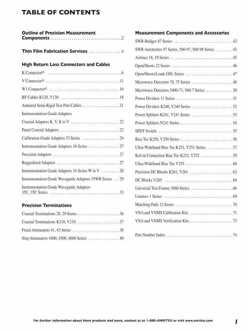
TABLE OF CONTENTS
Outline of Precision Measurement Components . . . . . . . . . . . . . . . . . . . . . . . . . . . . . . . . . .2
Thin Film Fabrication Services . . . . . . . . . . . . . . . 4
High Return Loss Connectors and Cables
K Connector® . . . . . . . . . . . . . . . . . . . . . . . . . . . . . . . . . . . . . . 6
V Connector® . . . . . . . . . . . . . . . . . . . . . . . . . . . . . . . . . . . . . . 11
W1 Connector® . . . . . . . . . . . . . . . . . . . . . . . . . . . . . . . . . . . . 16
RF Cables K120, V120 . . . . . . . . . . . . . . . . . . . . . . . . . . . . . . 18
Armored Semi-Rigid Test Port Cables . . . . . . . . . . . . . . . . . . . 21
Instrumentation Grade Adapters
Coaxial Adapters K, V, K to V . . . . . . . . . . . . . . . . . . . . . . . . . 22
Panel Coaxial Adapters . . . . . . . . . . . . . . . . . . . . . . . . . . . . . . 23
Calibration Grade Adapters 33 Series . . . . . . . . . . . . . . . . . . . 24
Instrumentation Grade Adapters 34 Series . . . . . . . . . . . . . . . . 27
Precision Adapters . . . . . . . . . . . . . . . . . . . . . . . . . . . . . . . . . . 27
Ruggedized Adapters . . . . . . . . . . . . . . . . . . . . . . . . . . . . . . . . 27
Instrumentation Grade Adapters 34 Series W to V . . . . . . . . . 28
Instrumentation Grade Waveguide Adapters 35WR Series . . . 29
Instrumentation Grade Waveguide Adapters 35U, 35C Series . . . . . . . . . . . . . . . . . . . . . . . . . . . . . . . . . . . . 33
Precision Terminations
Coaxial Terminations 28, 29 Series . . . . . . . . . . . . . . . . . . . . . 36
Coaxial Terminations K210, V210 . . . . . . . . . . . . . . . . . . . . . . 37
Fixed Attenuators 41, 43 Series . . . . . . . . . . . . . . . . . . . . . . . . 38
Step Attenuators 4400, 4500, 4600 Series . . . . . . . . . . . . . . . . 40
Measurement Components and Accessories
SWR Bridges 87 Series . . . . . . . . . . . . . . . . . . . . . . . . . . . . . . 42
SWR Autotesters 97 Series, 560-97, 560-98 Series . . . . . . . . . 43
Airlines 18, 19 Series . . . . . . . . . . . . . . . . . . . . . . . . . . . . . . . . 45
Open/Shorts 22 Series . . . . . . . . . . . . . . . . . . . . . . . . . . . . . . . 46
Open/Shorts/Loads OSL Series . . . . . . . . . . . . . . . . . . . . . . . . 47
Microwave Detectors 70, 75 Series . . . . . . . . . . . . . . . . . . . . . 48
Microwave Detectors 5400-71, 560-7 Series . . . . . . . . . . . . . . 50
Power Dividers 11 Series . . . . . . . . . . . . . . . . . . . . . . . . . . . . . 51
Power Dividers K240, V240 Series . . . . . . . . . . . . . . . . . . . . . 52
Power Splitters K241, V241 Series . . . . . . . . . . . . . . . . . . . . . 53
Power Splitters N241 Series . . . . . . . . . . . . . . . . . . . . . . . . . . . 54
SPDT Switch . . . . . . . . . . . . . . . . . . . . . . . . . . . . . . . . . . . . . . 55
Bias Tee K250, V250 Series . . . . . . . . . . . . . . . . . . . . . . . . . . . 56
Ultra-Wideband Bias Tee K251, V251 Series . . . . . . . . . . . . . 57
Kelvin Connection Bias Tee K252, V252 . . . . . . . . . . . . . . . . 59
Ultra-Wideband Bias Tee V255 . . . . . . . . . . . . . . . . . . . . . . . . 60
Precision DC Blocks K261, V261 . . . . . . . . . . . . . . . . . . . . . . 62
DC Blocks V265 . . . . . . . . . . . . . . . . . . . . . . . . . . . . . . . . . . . 64
Universal Test Fixture 3680 Series . . . . . . . . . . . . . . . . . . . . . 66
Limiters 1 Series . . . . . . . . . . . . . . . . . . . . . . . . . . . . . . . . . . . 69
Matching Pads 12 Series . . . . . . . . . . . . . . . . . . . . . . . . . . . . . 70
VNA and VNMS Calibration Kits . . . . . . . . . . . . . . . . . . . . . . 71
VNA and VNMS Verification Kits . . . . . . . . . . . . . . . . . . . . . . 73
Part Number Index . . . . . . . . . . . . . . . . . . . . . . . . . . . . . . . . . . 74

For further information about these products and more, contact us at 1-800-ANRITSU or visit www.anritsu.com
OUTLINE OF PRECISION MEASUREMENT COMPONENTS
2
Precision Components-PrecisionMeasurementsAnritsu is a leader in the design and production of precisionmicrowave components.
• Precision Coaxial Connector Systems to 110 GHz• Precision Coaxial and Waveguide to Coax Adapters• High Directivity SWR Autotesters and Bridges• RF Detectors• Precision Terminations and Air lines• Precision Fixed Attenuators• Precision Step Attenuators• Precision Power Dividers and Splitters• Precision Bias Tees• Broadband Microwave Limiters
Connector Design LeadershipAnritsu is the leader of high frequency microwave connectortechnology and is driven by an ongoing commitment to exceedcustomer needs. Anritsu created and trademarked the K Connector®
with coverage to 40 GHz, along with a complete family of 40 GHztest equipment. It was an immediate success and today is usedon many commercial components, test fixtures, and military systems.
The V Connector® offers coaxial coverage to 65 GHz and uses a1.85 mm geometry endorsed by the International ElectrotechnicalCommission (IEC). It mates with commercially available 2.4 mmconnectors.
The W1 Connector™ provides mode-free performance to 110 GHz anduses a 1.00 mm coaxial connector front side interface.
Coaxial and Waveguide to Coax AdaptersA series of precision measurement adapters are available to adapt oneconnector type to another. Poor adapter VSWR (or poor return loss)can be a major source of measurement error and, therefore adapters,must be carefully selected. Anritsu precision adapters typically have 6-12 dB better return loss than competitive units. Waveguide-to-CoaxAdapters are available to 65 GHz.
Precision Terminations and Air LinesAnritsu is recognized as the leader in the field of impedance standards.Anritsu air lines and terminations are unsurpassed for accuracy andimpedance match. Not only do these products increase measurementaccuracy, they also provide the only method of certifying the performanceof SWR Autotesters, bridges, directional couplers, and other devices.
Precision Fixed AttenuatorsAnritsu attenuators offer superior performance in a low cost package.The low VSWR (excellent return loss) minimizes signal reflections andsimultaneously reduces ripple effects in the output frequency response.This assures flat, consistent attenuation characteristics regardless ofother devices reflection characteristics. One of the simplest ways toimprove impedance match is to insert a precision attenuator betweenthe device under test and the source or RF detector. The 41K and 41VSeries attenuators are specifically designed for such applicationswhere accuracy is a basic requirement.
In addition to being available as individual units of 3, 6, 10, or 20 dB,the 41K and 41V Series Fixed Attenuators are also available in setswith certified calibration data. Available frequency ranges cover DC to26.5 GHz, 40 GHz, or 65 GHz.
Many other attenuator applications have as their principal objectivethe reduction of power. Since the attenuator might not be inserted at ameasurement point, the measurement precision discussed earlier is notrequired. In such a power-reducing system application, attenuators areoften required in large quantities, making price an important consideration.The 43K Series includes models covering DC to 26.5 GHz, and DC to40 GHz. All are available with 3, 6, 10, or 20 dB attenuation values. Allhave the Anritsu K Connectors and are compatible with SMA connectors.
Whatever your fixed attenuator needs might be, Anritsu providesthe solution.

For further information about these products and more, contact us at 1-800-ANRITSU or visit www.anritsu.com 3
Precision Step AttenuatorsAnritsu offers low loss, high precision step attenuators. Theseprogrammable step attenuators are available with 10 dB steps from0 to 70 dB or 0 to 110 dB ranges. DC to 40 GHz frequency rangeensures the broadest attenuation and frequency coverage available.Contact Anritsu for needs above 40 GHz or for custom step sizes.
Precision Power Dividers and SplittersAnritsu produces precision V Connector® dividers and splittersto 65 GHz and precision K Connector® dividers and splittersto 40 GHz.
All Anritsu power dividers are 3-resistor symmetrical designswith excellent amplitude and phase tracking. Anritsu powersplitters are 2-resistor designs, used to accurately split signalsfor ratio measurements.
Precision Bias TeesAnritsu Bias Tees are used to combine DC and RF for active devicemeasurements. Low RF throughline loss and low SWR ensurenegligible effect on measurements from 50 kHz to 65 GHz.
Broadband Microwave LimitersAnritsu broadband microwave limiters provide the widest frequencyrange available in a limiter. Designed to protect sensitive microwaveequipment, these limiters incorporate unique single-side limiting toprovide soft limiting characteristics over 10 MHz to 26.5 GHz.
High Directivity SWR Autotestersand BridgesSWR Autotesters and SWR Bridges are directional measurementdevices that separate the incident and the reflected signals of a deviceunder test. The reflected component can then be compared to theincident signal to determine the difference between the device’simpedance and its characteristic impedance.
An SWR bridge has a precision termination inside the bridge,eliminating the need for an external reference. An autotester furthersimplifies the user interface by incorporating a detector into the RFoutput that provides a DC output proportional to the DUT mismatch.
The directivity of the SWR Autotester or bridge is the measure of howwell the incident and reflected signals can be separated. For example,40 dB directivity means that the error signal in the output is 40 dBbelow a full reflection signal.
Anritsu’s high directivity bridges and autotesters set the standards forreflection measurements. High directivity translates to accuratemeasurements. Anritsu high directivity bridges are available for GPC-7, 50 ½ and 75 ½ Type N. High directivity autotestersare available with GPC-7, Type N, and SMA, 3.5, K Connectors®,
and V Connectors®.
RF DetectorsJust as directivity is the principal error contributor in reflectionmeasurements, the impedance match of the signal source and RFdetector is a significant error contributor intransmission measurements.
Anritsu offers a complete line of coaxial RF detectors covering from100 kHz to 50 GHz with the lowest SWR available. The excellentimpedance match of the detectors, along with that of the test porton the SWR Autotesters and bridges, minimize errors when makingsimultaneous transmission and measurements.
Calibration and Verification KitsAnritsu offers calibration kits which contain all of the precisioncomponents and tools required to calibrate an Anritsu VNA in aconnector style of your choice.
SpecialsAnritsu also manufactures assemblies and components to meetspecific customer requirements in both coaxial and waveguidestructures. These include such components as Connectors, Bias Tee,Step Attenuator, Detector, Power Sensors, Waveguide, CoaxialAdapters, and RF Cables etc.
When requesting quotations on special assemblies, as a minimumplease provide this information: frequency range, electricalcharacteristics, mechanical details and outline dimensions if any.

For further information about these products and more, contact us at 1-800-ANRITSU or visit www.anritsu.com
THIN FILM FABRICATION SERVICES
4
The Anritsu-USA Company is a global provider of RF and Microwavesolutions, wireless and digital components, and instruments for R&D,manufacturing, installation, and maintenance functions. The AnritsuThin Film Fab has over a 20 year track record in meeting the thin filmcircuit needs of its corporate parent. The Anritsu thin film services aresetup to fabricate thin film circuits to very precise requirements, andcontribute to Anritsu’s great success in the Wireless RF andMicrowave fields.
We are proud to offer the Anritsu Thin Film Fabrication Services asyour one-stop shop for any of your thin film fabrication needs. Weoffer customer specific services; including thin film depositions,resistor laser trimming, substrate laser drilling, photolithographypatterning and device singulation services. We can also turn your CADdesigns from the prototype level to high volume manufacturing withina very short period of time. Please refer to the Anritsu web site atwww.anritsu.com, call Anritsu at 408-778-2000, ext 1298, or [email protected] for more information.
Process Design ServicesAnritsu’s engineers have extensive experience with circuit processingtechnologies, and will be available to work with your designers incoming up with with the optimal fabrication processes to achieve yourcircuit design. In many cases, circuits can be fabricated and madeready for testing within five working days. Anritsu’s staff and facilitiesstand ready to assist you in further optimizing your deviceperformance, and bring your first prototypes to the manufacturingvolume that you need.
Substrate MaterialsThe following substrate materials are available: alumina, aluminumnitride, fused silica, glass, quartz, sapphire,and silicon.
Layout Design / Mask ProductionOur talented team of CAD professionals will help to layout yourengineering and prototype arrays and work closely with the mask shopto quickly release the mask set to meet your needs.
MetallizationThe following metals areavailable for thin filmdeposition by sputtering orelectroplating: Titanium,Titanium-Tungsten, Nickel,Gold, Copper, andPalladium.
PhotolithographyWe can routinely achieve accurate patterning of feature sizes down to0.001” (25.4 µm), and on a custom basis, down to 0.0004 in. (10 µm).Two photolithography processes are available: subtractive process(Etchback) or semi-additive process (Pattern Plate).
One Stop Shop • Rapid Prototyping • On Time Delivery • Competitive Pricing*
* Thin film fabrication services are available to U.S. customers only .

For further information about these products and more, contact us at 1-800-ANRITSU or visit www.anritsu.com 5
Insulation / PassivationPatterned polyimide and BCB films are available for use as a soldermask, thin film capacitor and insulating layer.
Filled Vias and Plated Through-HolesOption of solid filled vias, plated through-holes and edge wrap-aroundtechniques are available.
Laser Cutting and DrillingOur CO2 laser system can create features of virtually any planar shapewith positional accuracy of 0.001 in.
Resistor FilmsOur standard resistancelayer is Tantalum Nitride. Awide variety of sheetresistivities is available,with excellent temperaturecoefficients and long-termstability values.
Laser TrimmingOur laser trimmer can adjust resistor values up to an absolute toleranceof 0.1%.
SingulationSingulation is done using fully automatic dicing saws and diamondbased blades. Standard tolerance is ± 0.001 in. (2.5 µm).
Inspection andTestingOur products are 100% DCtested and inspected tomeet and exceed customerrequirements. Our QualityAssurance program isISO9001 certified and meetmost existing military andaerospace requirements.
Devices that we can manufacture include:• Circuits for microwave applications• Multilayer systems (MCM-D)• Thin film sensors• Resistor networks• Attenuator circuits for microwave applications• Hybrid circuits and power hybrids
Markets we serve:• Telecommunications• Defense• Automotive• Civil Aviation and Space• Calibration Industry• Biotechnology and Medical
* Thin film fabrication services are available to U.S. customers only .

The K Connector® is a precision coaxial connector system thatoperates up to 40 GHz. It is compatible with SMA, WSMA, and3.5 mm connectors. It is well suited to applications in components,systems, or instrumentation.
Visit www.anritsu.com for the latest information including installationinstructions, outline drawings, and RoHS compliance status.
K Connector® features• Excellent performance up to 40 GHz• Performance exceeding SMA below 18 GHz• Superior reliability• Compatibility with SMA, WSMA, and 3.5 mm• Complete testability on existing network analyzers• Components with -R suffix are RoHS compliant
Exceptional reliability and repeatabilityMicrowave connector reliability is affected by insertion force,outer conductor strength, stress relief while mating, and matingalignment. The K Connector exhibits exceptional performancein all of these areas.
For further information about these products and more, contact us at 1-800-ANRITSU or visit www.anritsu.com6
K CONNECTOR®
DC to 40 GHz
For proper seating, a standard SMA or 3.5 mm connector can requirein excess of 27N* of insertion force, In contrast, the K Connectorrequires only 2.3N*. The reduced wear on the female centerconductor improves reliability. In addition, the K Connectors outerconductor is four times thicker than that of SMA. Taken together,the lower insertion force and the thicker wall offer more reliableconnections than available from an SMA connector. Life tests showthat the K Connector makes greater than 10,000 connections withnegligible change in electrical characteristics.
All K Connectors, including the cable connectors, incorporate a featurethat eliminates a major cause of connector failure; misalignment ofthe male pin with respect to the female contacts. To solve the problemsthe K Connector male pin is deliberately made shorter than theSMA or 3.5 mm pin. With this arrangement, the outer housing isproperly aligned prior to the mating of the center conductors. Thus aproper, non-destructive alignment before mating is ensured.
The effect of pin gap on a connection is often overlooked, but is thedominant source of error in many connection systems. Pin gap isthe short length of smaller diameter caused when a connector pairis mated. Pin gap causes a discontinuity at the connector interface.The K Connector has considerably less susceptibility to pin gap thaneither SMA or 3.5 mm connectors.
Many connector manufacturers specify connector performanceassuming no pin gap, an unrealistic assumption. K Connectorsare specified assuming pin gap to be at its maximum tolerance,to provide you the assurance of real-world specifications.
CompatibilityThe K Connector interfaces electrically and mechanicallywith 3.5 mm connectors, including SMA and 3.5 mm withoutdegradation in performance.
Launcher designAt the heart of the K Connector product line are the launchers.As their name implies, the launchers “launch” (make the transition)from a microwave circuit (microstrip, suspended substrate, stripline,or coplanar waveguide) to a coaxial connector and an outsidetransmission line. The key to making the transition withoutcompromising electrical and mechanical objectives is the glassbead in the launcher assembly.
*Force is measured in Newtons (N).
SMA3.5
0
-10
-20
-30
-40Pin
Gap
Ret
urn
Loss
(dB
)
Frequency (GHz)20 30 40
K
Pin Gap
Male Center
Pin
Female Center
Pin
SMA/APC-3.5
K Connector
Shortened Male Pin Eliminates Damage to Female K Connector
Effect of Pin Gap

For further information about these products and more, contact us at 1-800-ANRITSU or visit www.anritsu.com 7
K CONNECTOR®
DC to 40 GHz
Low-reflection beadThe K Connector®’s standard glass bead has a 0.30 mm centerconductor and readily connects to fragile devices. The bead isappropriate for most applications employing Duroid® and ceramic(Alumina) microstrip, such as the 0.25 mm wide transmission lineon a 0.25 mm thick Alumina substrate. Applications using suspendedsubstrate geometry are equally well satisfied. The bead isconstructed of Corning 7070 glass and has a gold-plated centerconductor and a gold-plated Kovar® collar.
The outstanding design of the bead is largely accountable for theexcellent performance of the K Connector launchers. Because thesmall 0.30 mm pin introduces minimal discontinuity, return loss istypically better than 20 dB at 40 GHz and better than 25 dB below18 GHz. In addition, the design provides for soldering the bead toachieve a hermetic seal. 310°C max. soldering temperatureis recommended.
Both the sparkplug (screw-in) and the flange-mount K Connectorlaunchers offer an additional advantage over existing designs. Theselaunchers do not use an epoxy pin to secure the center conductor, asused in some SMA designs. Without an epoxy pin, the outerconductor remains solid, and thereby eliminates the leakage pathcommon to pin-captivated designs. Furthermore, K launchers have awall thickness that is four times that of typical launchers (0.8 vs.0.2 mm). The heavier wall results in superior resistance to over-torquing. Finally, the K Connector launcher can be removed forrepair without removal of the glass bead. This ensures that duringremoval the critical microcircuit-to-glass bead interface is notdisturbed, hermeticity is preserved, and the micro-circuit will not besubjected to the additional stress caused by heating to solderingtemperature. Hardware locking compound such as “RemovableLoctite®” should be used to further secure the screw-in launcher inits housing.
Complete familyVirtually every interface need can be satisfied by one or more ofthe K Connector items offered. There are six different models ofK Connector launchers. Two sparkplug (screw-in) launchers areavailable, the K102F-R female version and the K102M-R maleversion. Both screw into the housing that encloses the microwavecircuit, and, like all Anritsu launchers, they can be easily removedfor replacement or repair without unsoldering the glass bead and itsinterface to the microwave circuit.
When the housing that encloses the microwave circuit is not thickenough to support a threaded, screw-in launcher, flush-mounted(flange) launchers are required. Models with two mounting holes areavailable in both male and female versions, K103M-R and K103F-R.Two other models, the K104F-R and K104M-R, have four mountingholes. Mounting hole spacing is identical to that of similar SMAflange launchers. The glass bead interface, of course, is the samedesign used for the sparkplug launcher.
Cable connectorsBoth male and female cable connectors are available. The cableconnectors, K101M-R and K101F-R, use gold-plated, beryllium-copper center conductors for optimum performance and wearcharacteristics, Typical return loss at 40 GHz for finished cablesexceeds 16 dB (1.35 SWR).
Ø5.3
1/4 X 36 UNS-2A THD0.00 0.13
0.00 0.10
Ø 4.60 4.65
Ø4.65
.22
10.4
1.93 Ø1.27
Ø.97
R .203
R .41 BLEND 1.07
1.60
Ø1.27
Ø7.7 7.9 HEX Ø7.9 FLATS 7.1 1/4-36 UNS-2A
0.13 0.28
Ø4.55Ø2.92 Ø.91
2.9
0.00 0.10
0.00 0.10
16.24.44
Ø4.65
Dimensions in millimeters
K Connector® interface dimensions in metric measurements
Frequency (GHz)
Ret
urn
Loss
(dB
)
25
30
35
40
450 4 8 12 16 2420 28 32 36 40
WSMA + K
3.5 mm + KSMA + K
Return Loss Characteristics
Solder
Solder or Bond
Solder
0.30 mm
1.42 mm
1.98 mm ± 0.03
Bead
Microstrip, Coplanar Waveguide, Suspended Substrate
+0.08–0.00
Transition from Microcircuit to External Transmission Line
For further information about these products and more, contact us at 1-800-ANRITSU or visit www.anritsu.com8
K CONNECTOR®
DC to 40 GHz
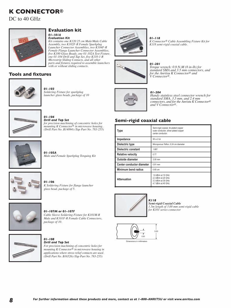
Evaluation kit01-101AEvaluation KitKit contains one K120 25 cm Male/Male CableAssembly, two K102F-R Female SparkplugLauncher Connector Assemblies, two K104F-RFemale Flange Launcher Connector Assemblies,five K100 Glass Beads, one 01-102A Test Fixture,one 01-104 Drill and Tap Set, five K110-1-RMicrostrip Sliding Contacts, and all otherparts and fixtures required to assemble launcherswith or without sliding contacts.
01-104Drill and Tap Setfor precision machining of concentric holes formounting K Connector® in microwave housing.(Drill Part No. B14094) (Tap Part No. 783-255)
01-105AMale and Female Sparkplug Torquing Kit
01-106K Soldering Fixture for flange launcher glass bead, package of 5.
01-107M or 01-107FCable Sleeve Soldering Fixture for K101M-RMale and K101F-R Female Cable Connectors, package of 10.
01-108Drill and Tap SetFor precision machining of concentric holes formounting K Connector® in microwave housing inapplications where stress relief contacts are used.(Drill Part No. B16526) (Tap Part No. 783-255)
3.00
0.81
Dimensions in millimeters
K118Semi-rigid Coaxial Cable1.5m length of 3.00 mm semi-rigid cablefor K101 series connector
Semi-rigid coaxial cable
Tools and fixtures
01-103Soldering Fixture for sparkplug launcher glass beads, package of 10
TypeSemi-rigid coaxial, tin-plated copper outer conductor, silver-plated copper center conductor.
Impedance 50 ± 2 Ω
Dielectric type Microporous Teflon, 0.24 cm diameter
Dielectric constant 1.687
Relative velocity 0.77
Outside diameter 3.00 mm
Center conductor diameter 0.81 mm
Minimum bend radius 0.65 cm
Attenuation1.6 dB/m at 10 GHz2.3 dB/m at 20 GHz3.3 dB/m at 30 GHz4.7 dB/m at 40 GHz
01-201 Torque wrench: 0.9 N-M (8 in-lb) forstandard SMA and 3.5 mm connectors, andfor the Anritsu K Connector® andV Connector®.
01-118K Connector® Cable Assembling Fixture Kit forK118 semi-rigid coaxial cable.
01-204 Handy stainless steel connector wrench forstandard SMA, 3.5 mm, and 2.4 mmconnectors, and for the Anristu K Connector®and V Connector®.

For further information about these products and more, contact us at 1-800-ANRITSU or visit www.anritsu.com 9
K CONNECTOR®
DC to 40 GHz
7.9 HEX 11.08.4 Ø4.06 for K101M-R
Ø3.05 for K101M-085-R
Ø3.02 for K101M-RØ2.26 for K101M-085-RDimensions in millimeters
K101M-R➃➅
K Male In-Line CableConnector, DC-40 GHzfor 3 mm cableK101M-085-R➃
for 2.16 mm cable
12.95.3
.5
Ø4.65Ø3.04
1/4-36 UNS-2A
7.9 HEX
Dimensions in millimeters
K101F-R➄➅
K Female In-Line CableConnector, DC-40 GHz for3 mm cable
16.2
8.4 .13 .28
Ø4.65
1/4-36 UNS-2A
7.1 FLATS
7.9 HEXDimensions in millimeters
K102M-R➂
K Male SparkplugLauncher Connector, DC-40 GHz
10.4
Ø5.33
.15
.30
Ø4.65Ø5.33
1/4-36 UNS-2A Dimensions in millimeters
K102F-R➂
K Female SparkplugLauncher Connector, DC-40 GHz
9.65.1 .05
.20
Ø5.3 Ø4.1
1.7
1/4-36 UNS-2A
5.7
2.8
15.9
12.2
2X Ø2.6 THRU
Dimensions in millimeters
K103F-RK Female FlangeLauncher, two-hole,DC-40 GHz
Launchers and cable connectors
13.1
8.4
7.9 HEX
.05
.20
Ø4.14
1.7
6.60
1.8
12.2 15.9
2X Ø2.6Dimensions in millimeters
K103M-RK Male Flange Launcher, two-hole, DC-40 GHz
Coupling nut tightening torque 1.36 N-m max
Material Passivated stainless steel with heat-treated beryllium coppercenter conductors
Pin depth 0.000 to -0.13 mm for male and female connectors
Temperature range -55°C to +125°C (200°C available; contact factory)
➀ Use with 01-104 or 01-108 Drill and Tap Sets➁ Use with 01-103 or 01-106 Soldering Fixtures➂ Use with 01-105A Male and Female Sparkplug
Torquing Kit➃ Use with 01-107M Cable Sleeve Fixture➄ Use with 01-107F Cable Sleeve Fixture➅ Use with 01-118 Cable Assembly Fixture Kit
9.6
5.1.05 .20
Ø5.3
1/4-36 UNS-2A
1.7
Ø4.1
8.64X Ø2.6 THRU
8.6
Ø15.912.7 SQ.Dimensions in millimeters
K104F-RK Female Flange Launcher, four-hole, DC-40 GHz
14.7
8.4.05 .20
7.92 HEX
1.7
Ø4.1
8.64X Ø2.6 THRU
8.6
12.7Ø15.9
Dimensions in millimeters
K104M-RK Male Flange Launcher, four-hole, DC-40 GHz

For further information about these products and more, contact us at 1-800-ANRITSU or visit www.anritsu.com10
K CONNECTOR®
DC to 40 GHz
Ordering informationPlease specify model/order number, name, and quantity when ordering.
Model/Order No. Name01-101A K Connector® (evaluation kit)
01-103 Soldering fixture for sparkplug launcher glass bead
01-104 Drill and tap set
01-105A Male and female sparkplug torquing kit
01-106 Soldering fixture for flange launcher glass bead
01-107F Cable sleeve soldering fixture, female connector
01-107M Cable sleeve soldering fixture, male connector
01-108 Drill and tap set
01-118 Cable assembling fixture for K118 semi-rigid coax cable
01-201 Torque wrench, for SMA, 3.5mm, and K Connector and V Connector
01-204 Anritsu stainless steel connector wrench
K110-1-R* Microstrip stress relief contact
K110-2-R* Stripline stress relief contact
K110-3-R* Microstrip stress relief contact
K101M-R K(m) in-line cable connector, DC to 40 GHz for K118 cable
K101M-085-R K(m) in-line cable connector, DC to 40 GHz for V085 cable
K101F-R K(f) in-line cable connector, DC to 40 GHz
K102M-R K(m) sparkplug launcher connector, DC to 40 GHz
K102F-R K(f) sparkplug launcher connector, DC to 40 GHz
K103M-RK(m) flange launcher connector, DC to 40 GHz, 2 mounting holes
K103F-R K(f) flange launcher connector, DC to 40 GHz, 2 mounting holes
K104M-RK(m) flange launcher connector, DC to 40 GHz, 4 mounting holes
K104F-R K(f) flange launcher connector, DC to 40 GHz, 4 mounting holes
K118Coaxial cable, 1.5m of 3.00 mm semi-rigid cable for K101 series connector
S110-1*Microstrip and coplaner waveguide stress relief contact for 0.38 mm glass feedthru center conductor
S110-3*Microstrip and coplaner waveguide stress relief contact for 0.38 mm glass feedthru center conductor
Stress relief contactsStress Relief Contacts provide an elegant yet simple solutionto relieving stress at the interface of the microcircuit and itsconnecting coaxial conductor. These contacts simply slide ontothe standard K100 and K100B glass bead pins.
.711
.305
.152 ±.030
.038
Dimensions in millimeters
.711
.305
.038.410
Dimensions in millimeters
.711
.203 .305
.406
.038
Dimensions in millimeters
K110-1-R➀ Microstrip andCoplaner Waveguide
K110-3-R➀ Microstrip
K110-2-R➀ Stripline
Frequency range DC to 40 GHz
Material 0.025 mm heat-treated BeCu
Plating Bondable gold over nickel
➀ Use with 01-108 Drill and Tap Set
3.18
0.74
1.40
1.93
0.305 DIA.Dimensions in millimeters
3.18
0.74
1.40
1.93
0.305 DIA.Dimensions in millimeters
K100➀➁
Glass Beads for K102, K103, and K104 connectorsNote: Glass Beads are not available through Anritsu.They can be purchased from Advanced Technology Group.101 Roundhill Drive, Rockaway, New Jersey 07866Tel: 973-627-6955, Fax: 973-627-5980www.advtechgr.com
K100B➀➁
High Hermeticity* Glass Beads for K102, K103,and K104 connectorsNote: Glass Beads are not available through Anritsu.They can be purchased from Advanced Technology Group.101 Roundhill Drive, Rockaway, New Jersey 07866Tel: 973-627-6955, Fax: 973-627-5980www.advtechgr.com
*Glass Bead Hermeticity Spec: Hermetic to 1 x 10⁻⁸ std cc He/sec at 1 atm differential
.038
Dimensions in millimeters.229
.152 ±.030
.711
S110-1 Microstrip and CoplanerWaveguide for 0.38 mm glassfeedthru center conductor
.038
Dimensions in millimeters
.711
.203 .305
.406
S110-3 Microstrip and CoplanerWaveguide for 0.38 mm glassfeedthru center conductor
*Sold in multiples of 10 only.

For further information about these products and more, contact us at 1-800-Anritsu or visit www.anritsu.com 11
V CONNECTOR®
DC to 65 GHz
The V Connector® is a reliable 1.85 mm device that operates upto 65 GHz. It is compatible with 2.4 mm connectors and isassembled using procedures that are similar to those used onK Connectors. It is well suited to applications in components,systems, or instrumentation.
Visit www.anritsu.com for the latest information including installationinstructions, outline drawings, and RoHS compliance status.
V Connector® features• Excellent performance up to 65 GHz• Low VSWR• Superior reliability• Low Loss• Components with -R suffix are RoHS compliant
Exceptional reliability and repeatabilityMicrowave connector reliability is affected by insertion force, outerconductor strength, stress relief while mating, and mating alignment.The V Connector exhibits exceptional performance in all of these areas.
For proper seating, the V Connector requires only 1/2 the insertionforce of a 2.4 mm connector. The reduced wear on the centerconductor equates to greater reliability. All V Connectors, including thecable connectors, incorporate another feature that eliminates a majorcause of connector failure: misalignment of the male pin with respectto the female. To solve the problem, the V Connector male pin isdeliberately made sufficiently short to prevent damage to the femaleconnector by misalignment. With this arrangement, the outer housingmust be properly aligned prior to the mating of the center conductors.Thus a proper, non-destructive alignment before mating is ensured.
The effect of pin gap on a connection is often overlooked, but isthe dominant source of error in many connection systems. Pin gap isthe short length of smaller diameter created when a connector pairis mated. Pin gap causes a discontinuity at the connector interface.The V Connector has considerably less susceptibility to pin gapthan 2.4 mm connectors.
Many connector manufacturers specify connector performanceassuming no pin gap, an unrealistic assumption. V Connectorsare specified assuming pin gap to be at its maximum tolerance, toprovide you the assurance of real-world specifications.
-10
-20
-30
-40Pin
Gap
Ret
urn
Loss
(dB
)
10 20Frequency (GHz)
30 40 50 60 70
Pin Gap
Male Center
Pin
Female Center
Pin
2.4 mm
V
Effect of Pin Gap
V Connector
Shortened Male Pin Eliminates Damage to Female V Connector
Launcher designAt the heart of the V Connector product line are the launchers.As their name implies, the launchers make the transition from amicrowave circuit (microstrip, suspended substrate, stripline, orcoplanar waveguide) to a coaxial connector and an outsidetransmission line. The key to making the transition withoutcompromising electrical and mechanical objectives is the glassbead in the launcher assembly.
Low-reflection glass beadThe V Connector’s standard glass bead has a unique 0.24 mm centerconductor and readily connects to fragile devices. The bead isappropriate for most applications employing Duroid and ceramic(Alumina) microstrip, such as the 0.25 mm wide center conductoron a 0.25 mm thick Alumina substrate. Applications usingsuspended substrate geometry are equally well satisfied. The bead isconstructed of Corning 7070 glass and has a gold-plated centerconductor and a gold-plated Kovar® collar.
The outstanding design of the bead is largely accountable for theexcellent performance of the V Connector launchers. In addition,the design provides for soldering the bead to achieve a hermeticseal. A max soldering temperature of 310°C is recommended. TheV Connector® launchers can be removed for repair withoutremoval of the glass bead. This ensures that during removal thecritical microcircuit-to-glass bead interface is not disturbed, thathermeticity is preserved, and that the microcircuit will not besubjected to the additional stress caused by heating to solderingtemperature. Hardware locking compound such as RemovableLoctite® should be used to further secure the launcher in its housing.

Complete familyThere are four different models of V Connector launchers. Twotypes of sparkplug (screw-in) launchers are available: the V102F-Rfemale version and the V102M-R male version. Both screw into thehousing that encloses the microwave circuit. And, like all Anritsulaunchers, they can be easily removed for replacement or repairwithout unsoldering the glass bead and its interface tothe microwave circuit.
For further information about these products and more, contact us at 1-800-Anritsu or visit www.anritsu.com12
V CONNECTOR®
DC to 65 GHz
Solder
Solder or Bond
Solder
Bead
Microstrip, Coplanar Waveguide, Suspended Substrate
1.42 mm
1.78 mm ± 0.02
+0.08–0.00
Transition from Microcircuit to Outside Transmission Line
Ø3.18
0.00 0.10
M6.0 X 0.75-6G
Ø7.9 FLATS 7.1
7.9 HEX
4.410.95.6
3.42.3
Ø.5
Ø4.7
Ø1.86
Ø.80
Ø7.7 0.00 0.10
0.00 0.10
0.00 0.10
M6.0 X 0.75-6G M7.0 X 0.75-6G
Ø4.78
Ø5.8 ±.1Ø1.85
Ø.8
3.04.9
11.5
3.9
Ø3.18
.19 TYPE BOTH
M + F
Dimensions in millimeters
V Connector interface dimensions
Evaluation kit01-301V Connector Evaluation Kit containsone V120MM - 25CM Male/MaleCable Assembly, two V102F FemaleSparkplug Launcher ConnectorAssemblies, two V103F Female FlangeLauncher Connector Assemblies, twoV101M-R Male In-line Cable ConnectorAssemblies, five V100 Glass Beads,one 01-304 Drill and Tap Set, one 01-302 Test Fixture, two 01-303Soldering Fixtures.
Tools and fixtures01-303Soldering Fixture for sparkplug launcherglass beads, package of 10.
01-304Drill and Tap Set for precision machining ofconcentric holes for mounting V Connectorin microwave housing. (Drill Part No. 783-568)(Tap Part No. 783-569)
When the housing that encloses the microwave circuit is not thickenough to support a threaded, screw-in launcher, flush-mounted(flange) launchers are required. Models with two mounting holesare available in both male and female versions, V103M-R andV103F-R. The mounting hole spacing is identical to that of similarSMA flange launchers. The glass bead interface, of course, is thesame design used for the sparkplug launcher.
Cable connectorsTo complement the high performance V085 cable, both male andfemale cable connectors are available. Typical return loss at 65 GHzfor finished cables exceeds 16 dB (1.35 SWR).
The V Connector® coaxial cable connectors use a 2.16 mm cablewith a microporous Teflon dielectric and a copper center conductor.The cable assemblies use the center conductor of the coax as themale pin. This is similar to the UT-141 SMA-type assembly and2.4 mm cable assemblies. The microporous Teflon dielectric hasmaximum phase stability and minimum insertion loss. This typeof cable assembly allows for easy assembly and maximum RFperformance; however, since the male pin is copper, the cableassemblies are not suitable for repeated connections. In applicationswhere the cable will be subject to more than 100 connections,we recommend that a connector saver be used.

For further information about these products and more, contact us at 1-800-Anritsu or visit www.anritsu.com 13
V CONNECTOR®
DC to 65 GHz
01-105AK and V Connector® Male and FemaleSparkplug Torquing Kit.
Semi-rigid coaxial cable
Launchers and cable connectors
V085semirigid coaxial cable1.5m length of 2.16 mm semirigid cable for V101 series connector
2.16
0.51
Dimensions in millimeters
01-309V Connector Cable Assembling Fixturefor V085 semi-rigid cable.
01-306Soldering Fixture for flange launcher glassbead, package of 5.
01-308Drill and Tap set for precision machining ofconcentric holes for mounting V Connector inmicrowave housing in applications wherestress-relief contacts are used.(Drill Part No. 55300) (Tap Part No. 783-569)
01-307M or 01-307FCable Sleeve Soldering Fixture for V101M-RMale and V101F-R Female Cable Connectors,package of 10.
Stress relief contactsStress Relief Contacts provide an elegant yet simple solutionto relieving stress at the interface of the microcircuit and itsconnecting coaxial conductor. These contacts simply slide onto thestandard glass bead pins and can be soldered, bonded or parallel-gapwelded to a circuit trace.
.165 ±.030
.038 ±.008
.254 .635
Dimensions in millimeters
V110-1-RMicrostrip and Coplanar Waveguidewhen using the V110-1, use 01-308Drill and Tap set to make therequired concentric holes.
Frequency range DC to 67 GHz
Material 0.025 mm heat-treated BeCu
Plating Bondable gold
Return loss (launchers only) 15 dB up to 65 GHz
Coupling nut tightening torque 1.36 N-m max
Material Passivated stainless steel with heat-treated beryllium copper center conductors
Pin depth 0.000 to -0.130 mm for male and female connectors
Temperature range -55°C to +125°C
TypeSemi-rigid coaxial, tin-plated copper outer conductor, silver-plated copper center conductor.
Impedance 50 ± 2 Ω
Dielectric type Microporous Teflon, 0.14 cm diameter
Dielectric constant 1.687
Relative velocity 0.77
Outside diameter 2.16 mm
Center conductor diameter 0.51 mm
Minimum bend radius 0.65 cm
Attenuation
2.3 dB/m at 10 GHz3.6 dB/m at 20 GHz4.3 dB/m at 30 GHz5.2 dB/m at 40 GHz7.2 dB/m at 60 GHz
01-204 Handy stainless steel connector wrench forstandard SMA, 3.5 mm, and 2.4 mm connectors,and for the Anritsu K Connector® and VConnector®.
01-201 Torque wrench: 0.9 N-M (8 in-lb) forstandard SMA and 3.5 mm connectors,and for the Anritsu K Connector® andV Connector®.

For further information about these products and more, contact us at 1-800-Anritsu or visit www.anritsu.com14
V CONNECTOR®
DC to 65 GHz
M7 X 0.75-6G
Ø5.8
11.5.19
Ø3.18
1.6 2X Ø2.6
15.9
12.2
5.69Dimensions in millimeters
V103F-RV Female FlangeLauncher, two-hole,DC-65 GHz
7.9 HEX
11.3
8.76
Ø2.26Ø4.06
Dimensions in millimeters
V101M-R➁➃
V Male In-Line CableConnector, DC-65 GHzfor V085 cable
Ø5.8
11.4
M7 X 0.75-6G
Ø2.26Ø3.18
7.9 HEX8.9 Dimensions in millimeters
M6 X 0.75-6G
Ø3.18
10.9
15.3
4.4
7.12
7.9 HEX
Dimensions in millimeters
V102M-R➀
V Male SparkplugLauncherConnector, DC-65 GHz
M7 X 0.75-6GM6 X 0.75-6G
Ø5.8
4.9
11.5
.19
Ø3.18Ø4.83 ±.05
Ø7.00
Dimensions in millimeters
V102F-R➀
V Female SparkplugLauncher Connector, DC-65 GHz
7.9 HEX
12.4
.19
Ø3.18
1.62X Ø2.6
15.912.2
5.7Dimensions in millimeters
V101F-R➂➃
V Female In-Line CableConnector, DC-65 GHzfor V085 cable
V103M-RV Male Flange Launcher, two-hole, DC-65 GHz
➀ Use with 01-105A Male and Female Sparkplug Torquing Kit➁ Use with 01-307M Cable Sleeve Fixture➂ Use with 01-307F Cable Sleeve Fixture➃ Use with 01-309 Cable Assembling Fixture
7.9 HEX
12.2
.19
Ø3.18
1.6
2X Ø2.6
15.912.2
5.7
Dimensions in millimeters
V103M-012V Male Flange Launcher,two-hole for 0.30 mmglass bead pin, DC-65 GHz
M7 X 0.75-6G
2X Ø2.6
15.9
12.2
Dimensions in millimeters
5.7
Ø3.18
.1911.3
1.6
V103F-012V Female FlangeLauncher, two-hole for0.30 mm glass bead pin, DC-65 GHz

For further information about these products and more, contact us at 1-800-Anritsu or visit www.anritsu.com 15
V CONNECTOR®
DC to 65 GHz
Ordering informationPlease specify model/order number, name, and quantity when ordering.
Model/Order No. Name
01-105A Male and female sparkplug torquing kit
01-201 Torque wrench, for SMA, 3.5mm, and K Connector and V Connector
01-204 Anritsu stainless steel connector wrench
01-301 V Connector® (evaluation kit)
01-303 Soldering fixture for sparkplug launcher glass bead
01-304 Drill and tap set
01-306 Soldering fixture for flange launcher glass bead
01-307M Cable sleeve soldering fixture, male connector
01-307F Cable sleeve soldering fixture, female connector
01-308 Drill and tap set
01-309 Cable assembling fixture
V085 Coaxial cable, 152 cm (5 feet) length of 2.16 mm semi-rigid cable
V101M-R V(m) in-line cable connector, DC to 65 GHz
V101F-R V(f) in-line cable connector, DC to 65 GHz
V102M-R V(m) sparkplug launcher connector, DC to 65 GHz
V102F-R V(f) sparkplug launcher connector, DC to 65 GHz
V103M-R V(m) flange launcher connector, DC to 65 GHz, 2 mounting holes
V103M-012V(m) flange launcher, 2 mounting holes for 0.30 mm glass bead pin, DC to 65 GHz
V103F-012V(f) flange launcher, 2 mounting holes for 0.30 mm glass bead pin, DC to 65 GHz
V103F-R V(f) flange launcher connector, DC to 65 GHz, 2 mounting holes
V110-1-R* Microstrip stress relief contact
➀ Use with 01-303 or 01-306 Soldering Fixtures➁ Use with 01-304 or 01-308 Drill and Tap Sets
2.79 ± 0.18
0.66 ± 0.10
1.73 ± 0.05
1.40 ± 0.05
Ø 0.24 ± 0.03
Dimensions in millimeters
2.79 ± 0.18
0.66 ± 0.10
1.73 ± 0.05
1.40 ± 0.05
Ø 0.24 ± 0.03
Dimensions in millimeters
V100➀➁
Glass Beads for V102, and V103 connectors(package of 5)Note: Glass Beads are not available through Anritsu.They can be purchased from Advanced Technology Group.101 Roundhill Drive, Rockaway, New Jersey 07866Tel: 973-627-6955, Fax: 973-627-5980www.advtechgr.com
V100B➀➁
High Hermeticity* Glass Beads for V102, andV103 connectors (package of 5)Note: Glass Beads are not available through Anritsu.They can be purchased from Advanced Technology Group.101 Roundhill Drive, Rockaway, New Jersey 07866Tel: 973-627-6955, Fax: 973-627-5980www.advtechgr.com
*Glass Bead Hermeticity Spec: Hermetic to 1 x 10⁻⁸ std cc He/sec at 1 atm differential
Environmental informationTests are performed per MIL-STD-202F.
Operating TemperatureRange
–55°C to +125°
Temperature Shock –55°C to +150°
Humidity 95% at 40°C, 96 hours, Test 103B, Condition B
Shock 100 G peak sawtooth, method 213, Test condition 1
Vibration
Sinewave: 10 Hz to 2000 Hz, 0.06” DA, method 204, test condition D
Random: 50 Hz to 2000 Hz, 11.6 Grms, Power Spectral Density 0.1Grms 2 Hz, Method 214, Test Condition 1, Letter D
Salt Spray 5% concentration for 48 hours, Method 101D, Condition B
Voltage withstanding 500 Vac RMS, 60 seconds, method 301
*Sold in multiples of 10 only.

For further information about these products and more, contact us at 1-800-Anritsu or visit www.anritsu.com16
W1 CONNECTOR®
DC to 110 GHz
The W1 Connector® Family is a complete coaxial connector systemwith mode-free performance to 110 GHz. Based on the 1.00 mmcoaxial connector front side interface as specified by IEEE Std 287,the W1 Connector is well suited for high frequency applicationsranging from components to systems and instrumentation.
Visit www.anritsu.com for the latest information including installationinstructions, outline drawings, and RoHS compliance status.
W1 Connector® features• Excellent RF Performance to 110 GHz• 50 Ω Impedance• Low VSWR• Industry Standard 1 mm Interface
Connector LaunchersThe W1 Connector® launcher family includes both male and femaleW1 Connectors. The W1 Connector® has an air dielectric interfacesimilar to K and V connectors. The center conductor is supported byAnritsu’s proprietary low-loss high temperature support bead on oneend and a glass bead (W1-102F and W1-102M ) or a Teflon bead(W1-105F and W1-105M) on the other end. The use of the hightemperature support bead allows the connector to be subjected to
temperature ranges up to 200°C for a short period. The centerconductor extends outside of the connector and allows the user tomake a direct pin overlap connection to the microwave circuit. Thethreads on the backside of the W1 Connector® allow the user toinstall the W1 Connector® by screwing it into the housing wall.Since Anritsu’s proprietary low-loss high temperature plastic bead isused, the user can solder the connector which has the glass bead intothe housing to achieve a hermetic connection.
Flange Mount ConnectorW1 two-hole Flange Mount female Connector is also available. Thecenter conductor of the connector is supported by a PPO® bead onthe front-end and by a Teflon bead on the back end. The centerconductor extends outside the connector, allowing for a direct pinoverlap connection to the microwave circuit.
Cable ConnectorBoth the male and female cable connectors are available. Typicalreturn loss at 110 GHz for finished cables exceeds 16 dB (1.35 SWR).
01-504, W1-6 mmTorque Wrench
01-506, W1-7 mmTorque Wrench
Tools
4.8 HEX
13.5
3.6 2.4 6.0 HEX
Dimensions in millimeters
W1-101MW1 Male In-line CableConnector, DC-110 GHz
6.0 HEX
M4 X 0.7-6G
3.9
13.6
3.6
4.8 HEX
Dimensions in millimeters
6.00 HEX1.57
13.67
5.57
1.9
Ø.127
.33
M7 X 0.75-6g
7.00
Ø4.48 Ø2.45Dimensions in millimeters
W1-102M, W1-105MW1 Male SparkplugConnector, DC-110 GHz
W1-101FW1 Female In-lineCable Connector, DC-110 GHz
Connectors
01-505, W1-6-7 mmOpen end Wrench

W1 CONNECTOR®
DC to 110 GHz
W047-2Semi-rigid coaxial cable,1.52 m length of 1.19mm semi-rigid cable forW1-101 series connector
1.19
0.318
Dimensions in millimeters
For further information about these products and more, contact us at 1-800-Anritsu or visit www.anritsu.com 17
Impedance 50 Ω
Frequency DC to 110 GHz
Insertion Loss 0.70 dB typical
Return Loss 1.38 to 110 GHz typical1.24 to 110 GHz typical (W1-101F, W1-101M)
Insulation Resistance >1200 MΩ
Center Conductor ContactResistance
6 mΩ typical
Maximum Power CW 6 W
Frontside Pin Depth 0 to 0.076 mm maximum
Backside Pin Protrusion 0.33 mm typical for W1-102F, W1-102M, W1-105F, W1-105M, 0.61 mm typical for W1-103F
Torque Coupling Nut 4 in-lb maximum
Torque W1 ConnectorInstallation
5 in-lb maximum
Hermeticity (W1-102F,W1-102M)
1 x 10⁻⁸ std cc He/sec at atmosphere differential
Environmental informationTests are performed per MIL-STD-202F.
Operating TemperatureRange
0° to +55°C
Storage TemperatureRange
-54° to +125°C for W1-102F, W1-102M, W1-105F, W1-105M-54° to +85°C for W1-103F
Humidity 25° to -40° and 25° to 125°C, method 107G, condition B
Shock 100G peak sawtooth, method 213, test condition 1
VibrationSinewave: 10 Hz to 2000 Hz, 0.06” DA, method 204, test condition DRandom: 50 Hz to 2000 Hz, 11.6 Grams, Power Spectral Density 0.1Grams2/Hz, Method 214, Test Condition 1, Letter D
Salt Spray 5% concentration for 48 hours, Method 101D, Condition B
Dielectric WithstandingVoltage
500 Vac RMS, 60 seconds, method 301
Specifications
W-101FW1-101M
Outer Conductor: Passivated Stainless SteelCenter Conductor: Beryllium-copper, gold plated over nickel per Mil-G-45204CCoupling Nut: Passivated Stainless SteelSleeve: Beryllium-copper, gold plated over nickel per Mil-G-45204CLock Screw: Passivated Stainless Steel
W1-102FW1-102M
Outer Conductor: Beryllium-copper, gold plated over nickel per Mil-G-45204CCenter Conductor: Beryllium-copper, gold plated over nickel per Mil-G-45204CCoupling Nut: Passivated Stainless SteelGlass Bead Center Pin: Kovar, gold pated over nickel per Mil-G-45204CGlass Bead Outer Conductor: Kovar, gold pated over nickel per Mil-G-45204CGlass Bead Dielectric: Corning 7070 GlassPlastic Bead Dielectric: Proprietary
W1-103FOuter Conductor: Passivated stainless steelCenter Conductor: Beryllium-copper, gold plated over nickel per Mil-G-45204CCoupling Nut: Passivated Stainless SteelPlastic Support Bead Dielectric: Polyphenylene Oxide Noryl
W1-105FW1-105M
Outer Conductor: Passivated stainless steelCenter Conductor: Beryllium-copper, gold plated over nickel per Mil-G-45204CCoupling Nut: Passivated Stainless SteelPlastic Support Bead Dielectric: Proprietary
Materials
Ordering informationPlease specify model/order number, name, and quantity when ordering.
Model/Order No. Name
W1-101F W1 Male In-line Cable Connector, DC-110 GHz
W1-101M W1 Female In-line Cable Connector, DC-110 GHz
W1-102F W1 Female Sparkplug Connector, Hermetic, DC-110 GHz
W1-102M W1 Male Sparkplug Connector, Hermetic, DC-110 GHz
W1-103F W1 Female Flange Connector, DC-110 GHz
W1-105F W1 Female Sparkplug Connector, DC-110 GHz
W1-105M W1 Male Sparkplug Connector, DC-110 GHz
W047-2 Semi-rigid Coaxial Cable
01-504 W1 6 mm Torque Wrench
01-505 W1 6-7mm Open end Wrench
01-506 W1 7 mm Torque Wrench
W1-102F, W1-105FW1 Female SparkplugConnector, DC-110 GHz
4.6
2.3
3.56
7.11
2X R5.12X Ø1.70
Ø3.00
M4 X 0.7-6G
Ø1.75Ø.13
7.0
1.3
2.13
.61
Dimensions in millimeters
W1-103FW1 Female FlangeConnector, DC-110 GHz
7.00
Ø4.48 Ø2.45M4 X 0.7-6g
M7 X 0.75-6g
2.81.57
12.275.57
1.9
Ø.127
.33Dimensions in millimeters

For further information about these products and more, contact us at 1-800-Anritsu or visit www.anritsu.com18
RF CABLESK120, V120 DC to 65 GHz
Semi-rigid RF cable features• Up to 65 GHz frequency ranges• Type N, K Connector®, and V Connector®• K Connector® compatibility with SMA and 3.5 mm• V Connector® compatibility with 2.4 mm
Specifications
K120 V120
Semi-rigid coaxial cable specificationsfor K Connectors®
Contact Anritsu Company for low loss, low VSWR cable bendingservices.
Semi-rigid coaxial cable specificationsfor V Connectors®
Temperature range: –55°C to +125°C
ModelFrequency
range (GHz)
Impedance (Ω) Length Connectors
N120-6 DC to 18 50 15 cm N(m) - N(m)
NS120MF-6 DC to 18 50 15 cm N(m) - SMA(f)
K120MM DC to 40 50 See table K(m) - K(m)
K120MF DC to 40 50 See table K(m) - K(f)
K120FF DC to 40 50 See table K(f) - K(f)
V120MM DC to 65 50 See table V(m) - V(m)
V120MF DC to 65 50 See table V(m) - V(f)
V120FF DC to 65 50 See table V(f) - V(f)
TypeSemi-rigid coaxial, tin-plated copper outer conductor, silver-plated copper center conductor.
Impedance 50 ± 2 Ω
Dielectric type Microporous Teflon, 0.24 cm diameter
Dielectric constant 1.687
Relative velocity 0.77
Outside diameter 3.00 mm
Center conductor diameter 0.81 mm
Minimum bend radius 0.65 cm
Attenuation1.6 dB/m at 10 GHz2.3 dB/m at 20 GHz3.3 dB/m at 30 GHz4.7 dB/m at 40 GHz
K118 semirigid coaxial cable 1.52 m length of 3.00 mmSemirigid cable for K101 series connector
TypeSemi-rigid coaxial, tin-plated copper outer conductor, silver-plated copper center conductor.
Impedance 50 ± 2 Ω
Dielectric type Microporous Teflon, 0.14 cm diameter
Dielectric constant 1.687
Relative velocity 0.77
Outside diameter 2.18 mm
Center conductor diameter 0.51 mm
Minimum bend radius 0.65 cm
Attenuation
2.3 dB/m at 10 GHz3.6 dB/m at 20 GHz4.3 dB/m at 30 GHz5.2 dB/m at 40 GHz7.2 dB/m at 60 GHz

RF CABLESK120, V120 DC to 65 GHz
Cable assembly part number reference
13.0 mm13.0 mm
(1/4-36 UNS-2A)(1/4-36 UNS-2A)
XXXXXX
"L"
K101F
K118
K101F
Dimensions in millimeters
K120FF outline
V120FF outline
V120MM outlineV120MF outline
11.0 mm 13.0 mm
"L"
XXXXXX
K118
K101F(1/4-36 UNS-2A)
K101M(1/4-36 UNS-2B)
7.9 mm HEX
Dimensions in millimeters
11.4 mm11.4 mmV085
XXXXXX
V-FEMALE V-FEMALE
"L"
Dimensions in millimeters
V-FEMALEV-MALE
"L"
V085 11.4 mm11.3 mm
XXXXXX
Dimensions in millimeters
V-MALEV-MALE
"L"
XXXXXX
V08511.3 mm 11.3 mm
Dimensions in millimeters
K120MF outline
(1/4-36 UNS-2B)
(1/4-36 UNS-2B)
XXXXXX
"L"
11.0 mm11.0 mm
K101M
K101M
K118
Dimensions in millimeters
K120MM outline
"L"
12.7 mm
XXXXXX
29 mm
semi-rigid
SMA Female
3.58 mm
N MaleDimensions in millimeters
NS120MF-6 outline
XXXXXX
29 mm29 mm
"L"
3.58 mm semi-rigid
N MaleN Male
Dimensions in millimeters
N120-6 outline
Length Metric cable assemblies
cm K120MM K120MF K120FF V120MM V120MF V120FF5 K120MM-5CM K120MF-5CM K120FF-5CM V120MM-5CM V120MM-5CM V120FF-5CM
10 K120MM-10CM K120MF-10CM K120FF-10CM V120MM-10CM V120MM-10CM V120FF-10CM
15 K120MM-15CM K120MF-15CM K120FF-15CM V120MM-15CM V120MM-15CM V120FF-15CM
20 K120MM-20CM K120MF-20CM K120FF-20CM V120MM-20CM V120MM-20CM V120FF-20CM
25 K120MM-25CM K120MF-25CM K120FF-25CM V120MM-25CM V120MM-25CM V120FF-25CM
30 K120MM-30CM K120MF-30CM K120FF-30CM V120MM-30CM V120MM-30CM V120FF-30CM
35 K120MM-35CM K120MF-35CM K120FF-35CM V120MM-35CM V120MM-35CM V120FF-35CM
40 K120MM-40CM K120MF-40CM K120FF-40CM V120MM-40CM V120MM-40CM V120FF-40CM
45 K120MM-45CM K120MF-45CM K120FF-45CM V120MM-45CM V120MM-45CM V120FF-45CM
50 K120MM-50CM K120MF-50CM K120FF-50CM V120MM-50CM V120MM-50CM V120FF-50CM
60 K120MM-60CM K120MF-60CM K120FF-60CM V120MM-60CM V120MM-60CM V120FF-60CM
70 K120MM-70CM K120MF-70CM K120FF-70CM V120MM-70CM V120MM-70CM V120FF-70CM
80 K120MM-80CM K120MF-80CM K120FF-80CM V120MM-80CM V120MM-80CM V120FF-80CM
90 K120MM-90CM K120MF-90CM K120FF-90CM V120MM-90CM V120MM-90CM V120FF-90CM
100 K120MM-100CM K120MF-100CM K120FF-100CM V120MM-100CM V120MM-100CM V120FF-100CM
125 K120MM-125CM K120MF-125CM K120FF-125CM V120MM-125CM V120MM-125CM V120FF-125CM
150 K120MM-150CM K120MF-150CM K120FF-150CM V120MM-150CM V120MM-150CM V120FF-150CM
For further information about these products and more, contact us at 1-800-Anritsu or visit www.anritsu.com 19

For further information about these products and more, contact us at 1-800-Anritsu or visit www.anritsu.com
RF CABLESK120, V120 DC to 65 GHz
Ordering informationPlease specify model/order number, name and quantity when ordering.
Model/Order No. Name
Cable, semi-rigid
N120-6 001 to 18 GHz, 50 Ω, 15 cm, N(m) to N(m)
NS120MF-6 0.01 to 18 GHz, 50 Ω, 15 cm, N(m) to SMA(f)
K120MM-5CM DC to 40 GHz, 50 Ω, 5 cm, K(m) to K(m)
K120MM-10CM DC to 40 GHz, 50 Ω, 10 cm, K(m) to K(m)
K120MM-15CM DC to 40 GHz, 50 Ω, 15 cm, K(m) to K(m)
K120MM-20CM DC to 40 GHz, 50 Ω, 20 cm, K(m) to K(m)
K120MM-25CM DC to 40 GHz, 50 Ω, 25 cm, K(m) to K(m)
K120MM-30CM DC to 40 GHz, 50 Ω, 30 cm, K(m) to K(m)
K120MM-35CM DC to 40 GHz, 50 Ω, 35 cm, K(m) to K(m)
K120MM-40CM DC to 40 GHz, 50 Ω, 40 cm, K(m) to K(m)
K120MM-45CM DC to 40 GHz, 50 Ω, 45 cm, K(m) to K(m)
K120MM-50CM DC to 40 GHz, 50 Ω, 50 cm, K(m) to K(m)
K120MM-60CM DC to 40 GHz, 50 Ω, 60 cm, K(m) to K(m)
K120MM-70CM DC to 40 GHz, 50 Ω, 70 cm, K(m) to K(m)
K120MM-80CM DC to 40 GHz, 50 Ω, 80 cm, K(m) to K(m)
K120MM-90CM DC to 40 GHz, 50 Ω, 90 cm, K(m) to K(m)
K120MM-100CM DC to 40 GHz, 50 Ω, 100 cm, K(m) to K(m)
K120MM-125CM DC to 40 GHz, 50 Ω, 125 cm, K(m) to K(m)
K120MM-150CM DC to 40 GHz, 50 Ω, 150 cm, K(m) to K(m)
K120MF-5CM DC to 40 GHz, 50 Ω, 5 cm, K(m) to K(f)
K120MF-10CM DC to 40 GHz, 50 Ω, 10 cm, K(m) to K(f)
K120MF-15CM DC to 40 GHz, 50 Ω, 15 cm, K(m) to K(f)
K120MF-20CM DC to 40 GHz, 50 Ω, 20 cm, K(m) to K(f)
K120MF-25CM DC to 40 GHz, 50 Ω, 25 cm, K(m) to K(f)
K120MF-30CM DC to 40 GHz, 50 Ω, 30 cm, K(m) to K(f)
K120MF-35CM DC to 40 GHz, 50 Ω, 35 cm, K(m) to K(f)
K120MF-40CM DC to 40 GHz, 50 Ω, 40 cm, K(m) to K(f)
K120MF-45CM DC to 40 GHz, 50 Ω, 45 cm, K(m) to K(f)
K120MF-50CM DC to 40 GHz, 50 Ω, 50 cm, K(m) to K(f)
K120MF-60CM DC to 40 GHz, 50 Ω, 60 cm, K(m) to K(f)
K120MF-70CM DC to 40 GHz, 50 Ω, 70 cm, K(m) to K(f)
K120MF-80CM DC to 40 GHz, 50 Ω, 80 cm, K(m) to K(f)
K120MF-90CM DC to 40 GHz, 50 Ω, 90 cm, K(m) to K(f)
K120MF-100CM DC to 40 GHz, 50 Ω, 100 cm, K(m) to K(f)
K120MF-125CM DC to 40 GHz, 50 Ω, 125 cm, K(m) to K(f)
K120MF-150CM DC to 40 GHz, 50 Ω, 150 cm, K(m) to K(f)
K120FF-5CM DC to 40 GHz, 50 Ω, 5 cm, K(f) to K(f)
K120FF-10CM DC to 40 GHz, 50 Ω, 10 cm, K(f) to K(f)
K120FF-15CM DC to 40 GHz, 50 Ω, 15 cm, K(f) to K(f)
K120FF-20CM DC to 40 GHz, 50 Ω, 20 cm, K(f) to K(f)
K120FF-25CM DC to 40 GHz, 50 Ω, 25 cm, K(f) to K(f)
K120FF-30CM DC to 40 GHz, 50 Ω, 30 cm, K(f) to K(f)
K120FF-35CM DC to 40 GHz, 50 Ω, 35 cm, K(f) to K(f)
K120FF-40CM DC to 40 GHz, 50 Ω, 40 cm, K(f) to K(f)
K120FF-45CM DC to 40 GHz, 50 Ω, 45 cm, K(f) to K(f)
K120FF-50CM DC to 40 GHz, 50 Ω, 50 cm, K(f) to K(f)
K120FF-60CM DC to 40 GHz, 50 Ω, 60 cm, K(f) to K(f)
K120FF-70CM DC to 40 GHz, 50 Ω, 70 cm, K(f) to K(f)
K120FF-80CM DC to 40 GHz, 50 Ω, 80 cm, K(f) to K(f)
K120FF-90CM DC to 40 GHz, 50 Ω, 90 cm, K(f) to K(f)
K120FF-100CM DC to 40 GHz, 50 Ω, 100 cm, K(f) to K(f)
K120FF-125CM DC to 40 GHz, 50 Ω, 125 cm, K(f) to K(f)
K120FF-150CM DC to 40 GHz, 50 Ω, 150 cm, K(f) to K(f)
Model/Order No. Name
Cable, semi-rigid
V120MM-5CM DC to 65 GHz, 50 Ω, 5 cm, V(m) to V(m)
V120MM-10CM DC to 65 GHz, 50 Ω, 10 cm, V(m) to V(m)
V120MM-15CM DC to 65 GHz, 50 Ω, 15 cm, V(m) to V(m)
V120MM-20CM DC to 65 GHz, 50 Ω, 20 cm, V(m) to V(m)
V120MM-25CM DC to 65 GHz, 50 Ω, 25 cm, V(m) to V(m)
V120MM-30CM DC to 65 GHz, 50 Ω, 30 cm, V(m) to V(m)
V120MM-35CM DC to 65 GHz, 50 Ω, 35 cm, V(m) to V(m)
V120MM-40CM DC to 65 GHz, 50 Ω, 40 cm, V(m) to V(m)
V120MM-45CM DC to 65 GHz, 50 Ω, 45 cm, V(m) to V(m)
V120MM-50CM DC to 65 GHz, 50 Ω, 50 cm, V(m) to V(m)
V120MM-60CM DC to 65 GHz, 50 Ω, 60 cm, V(m) to V(m)
V120MM-70CM DC to 65 GHz, 50 Ω, 70 cm, V(m) to V(m)
V120MM-80CM DC to 65 GHz, 50 Ω, 80 cm, V(m) to V(m)
V120MM-90CM DC to 65 GHz, 50 Ω, 90 cm, V(m) to V(m)
V120MM-100CM DC to 65 GHz, 50 Ω, 100 cm, V(m) to V(m)
V120MM-125CM DC to 65 GHz, 50 Ω, 125 cm, V(m) to V(m)
V120MM-150CM DC to 65 GHz, 50 Ω, 150 cm, V(m) to V(m)
V120MF-5CM DC to 65 GHz, 50 Ω, 5 cm, V(m) to V(f)
V120MF-10CM DC to 65 GHz, 50 Ω, 10 cm, V(m) to V(f)
V120MF-15CM DC to 65 GHz, 50 Ω, 15 cm, V(m) to V(f)
V120MF-20CM DC to 65 GHz, 50 Ω, 20 cm, V(m) to V(f)
V120MF-25CM DC to 65 GHz, 50 Ω, 25 cm, V(m) to V(f)
V120MF-30CM DC to 65 GHz, 50 Ω, 30 cm, V(m) to V(f)
V120MF-35CM DC to 65 GHz, 50 Ω, 35 cm, V(m) to V(f)
V120MF-40CM DC to 65 GHz, 50 Ω, 40 cm, V(m) to V(f)
V120MF-45CM DC to 65 GHz, 50 Ω, 45 cm, V(m) to V(f)
V120MF-50CM DC to 65 GHz, 50 Ω, 50 cm, V(m) to V(f)
V120MF-60CM DC to 65 GHz, 50 Ω, 60 cm, V(m) to V(f)
V120MF-70CM DC to 65 GHz, 50 Ω, 70 cm, V(m) to V(f)
V120MF-80CM DC to 65 GHz, 50 Ω, 80 cm, V(m) to V(f)
V120MF-90CM DC to 65 GHz, 50 Ω, 90 cm, V(m) to V(f)
V120MF-100CM DC to 65 GHz, 50 Ω, 100 cm, V(m) to V(f)
V120MF-125CM DC to 65 GHz, 50 Ω, 125 cm, V(m) to V(f)
V120MF-150CM DC to 65 GHz, 50 Ω, 150 cm, V(m) to V(f)
V120FF-5CM DC to 65 GHz, 50 Ω, 5 cm, V(f) to V(f)
V120FF-10CM DC to 65 GHz, 50 Ω, 10 cm, V(f) to V(f)
V120FF-15CM DC to 65 GHz, 50 Ω, 15 cm, V(f) to V(f)
V120FF-20CM DC to 65 GHz, 50 Ω, 20 cm, V(f) to V(f)
V120FF-25CM DC to 65 GHz, 50 Ω, 25 cm, V(f) to V(f)
V120FF-30CM DC to 65 GHz, 50 Ω, 30 cm, V(f) to V(f)
V120FF-35CM DC to 65 GHz, 50 Ω, 35 cm, V(f) to V(f)
V120FF-40CM DC to 65 GHz, 50 Ω, 40 cm, V(f) to V(f)
V120FF-45CM DC to 65 GHz, 50 Ω, 45 cm, V(f) to V(f)
V120FF-50CM DC to 65 GHz, 50 Ω, 50 cm, V(f) to V(f)
V120FF-60CM DC to 65 GHz, 50 Ω, 60 cm, V(f) to V(f)
V120FF-70CM DC to 65 GHz, 50 Ω, 70 cm, V(f) to V(f)
V120FF-80CM DC to 65 GHz, 50 Ω, 80 cm, V(f) to V(f)
V120FF-90CM DC to 65 GHz, 50 Ω, 90 cm, V(f) to V(f)
V120FF-100CM DC to 65 GHz, 50 Ω, 100 cm, V(f) to V(f)
V120FF-125CM DC to 65 GHz, 50 Ω, 125 cm, V(f) to V(f)
V120FF-150CM DC to 65 GHz, 50 Ω, 150 cm, V(f) to V(f)
20
For further information about these products and more, contact us at 1-800-ANRITSU or visit www.anritsu.com 21
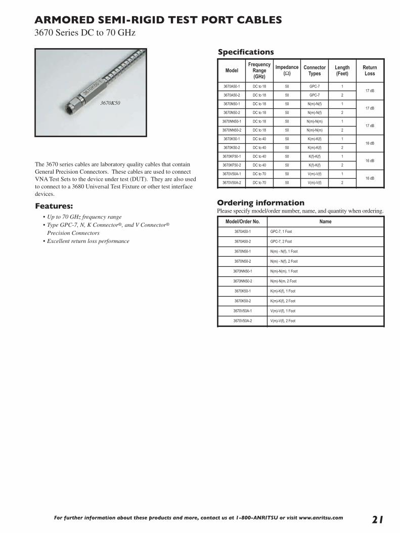
ARMORED SEMI-RIGID TEST PORT CABLES3670 Series DC to 70 GHz
3670K50
The 3670 series cables are laboratory quality cables that containGeneral Precision Connectors. These cables are used to connectVNA Test Sets to the device under test (DUT). They are also usedto connect to a 3680 Universal Test Fixture or other test interfacedevices.
Features:• Up to 70 GHz frequency range• Type GPC-7, N, K Connector®, and V Connector®
Precision Connectors• Excellent return loss performance
Ordering informationPlease specify model/order number, name, and quantity when ordering.
Specifications
Model/Order No. Name
3670A50-1 GPC-7, 1 Foot
3670A50-2 GPC-7, 2 Foot
3670N50-1 N(m) - N(f), 1 Foot
3670N50-2 N(m) - N(f), 2 Foot
3670NN50-1 N(m)-N(m), 1 Foot
3670NN50-2 N(m)-N(m, 2 Foot
3670K50-1 K(m)-K(f), 1 Foot
3670K50-2 K(m)-K(f), 2 Foot
3670V50A-1 V(m)-V(f), 1 Foot
3670V50A-2 V(m)-V(f), 2 Foot
ModelFrequency
Range (GHz)
Impedance(Ω)
ConnectorTypes
Length (Feet)
Return Loss
3670A50-1 DC to 18 50 GPC-7 117 dB
3670A50-2 DC to 18 50 GPC-7 2
3670N50-1 DC to 18 50 N(m)-N(f) 117 dB
3670N50-2 DC to 18 50 N(m)-N(f) 2
3670NN50-1 DC to 18 50 N(m)-N(m) 117 dB
3670NN50-2 DC to 18 50 N(m)-N(m) 2
3670K50-1 DC to 40 50 K(m)-K(f) 116 dB
3670K50-2 DC to 40 50 K(m)-K(f) 2
3670KF50-1 DC to 40 50 K(f)-K(f) 116 dB
3670KF50-2 DC to 40 50 K(f)-K(f) 2
3670V50A-1 DC to 70 50 V(m)-V(f) 116 dB
3670V50A-2 DC to 70 50 V(m)-V(f) 2

For further information about these products and more, contact us at 1-800-Anritsu or visit www.anritsu.com22
COAXIAL ADAPTERSK, V, K to V DC to 65 GHz
K230B
V230
K222B
K224B
The K220 and 34V Series of precision adapters enable accuratemeasurements with K or V connectors. Every adapter is fullyspecified and 100% tested to ensure low reflections and optimumperformance over the DC to 65 GHz range.
Precision K and V adapter features• K Connector® DC to 40 GHz frequency range• V Connector® DC to 65 GHz frequency range• Low SWR and insertion loss
K220B
7.93 HEX 6.35 DIA. 5.33 ACROSS FLATS
K MALE CONNECTOR (1/4 - 36 UNS - 2B) 2X
7.0 5.84
20.6
Dimensions in Millimeters
K220B outline
Specifications
K222B
6.35 DIA.5.33 ACROSS FLATS
K FEMALE CONNECTOR (1/4 - 36 UNS - 2A) 2X
7.0 5.84
19.1
Dimensions in Millimeters
K222B outline
K224B
7.93 HEX 6.35 DIA. 5.33 ACROSS FLATSK FEMALE CONNECTOR (1/4 - 36 UNS - 2A)
7.0 5.84
19.8
Dimensions in Millimeters
K MALE CONN. (1/4 - 36 UNS - 2B)
K224B outline
31.7
8.6411
34VK50
Dimensions in Millimeters
7.92 DIAV-MALE CONNECTOR M7.0 X .75 6H
K-MALE CONNECTOR(1/4 -36 UNS-2B)
34VK50 outline
24.4
34VFKF50
8.647
VF-FEMALE CONNECTOR(M7.0 X .75-6G)
7.92 DIA KF-FEMALE CONNECTOR(1/4-36 UNS-2A)
Dimensions in Millimeters
34VFKF50 outline
34VV50
31.4
11 8.64
Dimensions in Millimeters
V MALE CONNECTOR M7.0 X .75-6H 2X
7.92 DIA
34VV50 outline
34VFVF50
23.6
7 8.64
7.92 DIAV FEMALE CONNECTORM7.0 X .75-6G 2X
Dimensions in Millimeter
34VFVF50 outline
Dimensions in Millimeters
8.6411
27.5
34VVF50
V MALE CONNECTOR M7.0 X .75-6H
V FEMALE CONNECTORM7.0 X .75-6G
7.92 DIA
34VVF50 outline
8.6411
34VKF50
28.5
Dimensions in Millimeters
7.92 DIA K-FEMALE CONNECTOR(1/4-36 UNS-2A)
V-MALE CONNECTORM7.0 X .75 - 6G
34VKF50 outline
727.8
8.64
34VFK50
7.92 DIAK-MALE CONNECTOR(1/4 -36 UNS-2B)
VF-FEMALE CONNECTOR(M7.0 X .75-6G)
Dimensions in Millimeters
34VFK50 outline
Temperature range: –55°C to +125°C
Model Frequency range (GHz) Connectors SWR
K220BK222BK224B
DC to 40K(m) to K(m)K(f) to K(f)
K(f) to K(m)1.12
34VK5034VKF50
DC to 40V(m) to K(m)V(m) to K(f)
1.3
34VFK5034VFKF50
DC to 40V(f) to K(m)V(f) to K(f)
1.3
34VV5034VFVF5034VVF50
DC to 65V(m) to V(m)V(f) to V(f)
V(m) to V(f)1.5

COAXIAL ADAPTERSK, V, K to V DC to 65 GHz
K-MALE CONNECTOR (1/4 - 36 UNS - 2B) 2X
8.64 ACROSS FLAT
6.60 ±0.50 5.84
20.6
Dimensions in Millimeters
3/8 - 32 UNEF - 2A
12.7 DIA.
1.02
8.76
9.5 mm CLEAR
MOUNTING HOLE
K230B outline
8.64 ACROSS FLAT 3/8 - 32 UNEF-2A
19.1
Dimensions in Millimeters
K FEMALE CONNECTOR1/4 - 36 UNS-2A 2X
6.67 ±0.50 5.841.02
8.76
9.5 mm CLEAR
MOUNTING HOLE
12.7 DIA.
8.76
9.5 mmCLEAR
MOUNTING HOLE 19.6Dimensions in Millimeters
1.025.847.5
7.92 HEX
8.64 ACROSS FLAT3/8 - 32 UNEF - 2A
K-MALE CONNECTOR (1/4 - 36 UNS - 2B)
K FEMALE CONNECTOR1/4 - 36 UNS-2A
12.7 DIA.
K232B outline
K234B outline
The K230 Series is the panel-mount version of the K220 SeriesAdapters. These units mount in a standard 9.5 mm “D” hole.
K and V panel adapter features• Precision, panel-mounted feedthru adapter• Broad, DC to 65 GHz frequency range
K panel adapter specifications
Ordering informationPlease specify model/order number, name and quantity when ordering.
11.56
31.7
1.028.64
12.7 DIA.
17.1
V MALE CONNECTORM7.0 X .75-6G
V MALE CONNECTORM7.0 X .75-6H
3/8-32 UNS-2A
8.76
9.5 mmCLEAR
MOUNTING HOLE
Dimensions in Millimeters
V230 outline22.9
7.14 8.641.02
3/8-32 UNS-2A
V FEMALE CONNECTORM7.0 X .75-6H
V FEMALE CONNECTORM7.0 X .75-6G
8.76
9.5 mmCLEAR
MOUNTING HOLE
Dimensions in Millimeters
12.7 DIA.
17.1
7.14 8.641.02
27.3
3/8-32 UNS-2A
V FEMALE CONNECTORM7.0 X .75-6G
V MALE CONNECTORM7.0 X .75-6H
Dimensions in Millimeters
8.76
9.5 mmCLEAR
MOUNTING HOLE
12.7 DIA.
17.1
V232 outline
V234 outline
Model Frequency range (GHz) Connectors SWRK230B
DC to 40
K(m) to K(m)
1.12K232B K(f) to K(f)
K234B K(f) to K(m)
Model Frequency range (GHz) Connectors SWRV230
DC to 65
V(m) to V(m)
1.5V232 V(f) to V(f)
V234 V(f) to V(m)
Model/Order No. Name
Precision adapter
K220B DC to 40 GHz, 50 Ω, K(m)-K(m)
K222B DC to 40 GHz, 50 Ω, K(f)-K(f)
K224B DC to 40 GHz, 50 Ω, K(m)-K(f)
K230B DC to 40 GHz, 50 Ω, K(m)-K(m)
K232B DC to 40 GHz, 50 Ω, K(f)-K(f)
K234B DC to 40 GHz, 50 Ω, K(f)-K(m)
34VK50 DC to 46.5 GHz, 50 Ω, V(m)-K(m)
34VKF50 DC to 40 GHz, 50 Ω, V(m)-K(f)
34VFK50 DC to 40 GHz, 50 Ω, V(f)-K(m)
34VFKF50 DC to 40 GHz, 50 Ω, V(f)-K(f)
34VV50 DC to 65 GHz, 50 Ω, V(m)-V(m)
34VVF50 DC to 65 GHz, 50 Ω, V(m)-V(f)
34VFVF50 DC to 65 GHz, 50 Ω, V(f)-V(f)
V230 DC to 65 GHz, 50 Ω, V(m)-V(m)
V232 DC to 65 GHz, 50 Ω, V(f)-V(f)
V234 DC to 65 GHz, 50 Ω, V(f)-V(m)
V panel adapter specifications
For further information about these products and more, contact us at 1-800-Anritsu or visit www.anritsu.com 23

For further information about these products and more, contact us at 1-800-ANRITSU or visit www.anritsu.com24
CALIBRATION GRADE ADAPTERS33 Series DC to 110 GHz
The 33 Series of precision phase equal adapters enable accuratemeasurements with Anritsu V Connector®, K Connector®, W1Connector®, WSMA, and Type N interfaces. Every adapter is fullyspecified and 100% tested to ensure low reflections and optimumphase performance over a broad frequency range.
Features• Low SWR and insertion loss• DC to 110 GHz, with W1 Connector® interface• DC to 70 GHz, with V Connector® interface• DC to 40 GHz, with K Connector® interface• 50 Ω impedance
33VV50C
33KK50B
33VFVF50C
33KFKF50B
33KKF50B
33VVF50C
1/4-36 UNS-2A 7.92 DIA 1/4-36 UNX-2B
8.4
25.7
9.9
7.9
Dimensions in Millimeters
33SSF50 outline
7.1
2X1/4-36 UNS-2A 7.92 DIA
9.9
24.8
Dimensions in Millimeters
33SFSF50 outline
Ø22.2
18.5 20.1
59.3
12.7
2X5/8-24 UNEF-2B
Ø15.7 19.0
Dimensions in Millimeters
33NN50B outline
7.9
2X1/4-36 UNX-2B 7.92 DIA
26.7
9.9
Dimensions in Millimeters
33SS50 outline
72.6
18.5 27.3
15.7
2X5/8-24 UNEF-2A
12.7
Dimensions in Millimeters
33NFNF50B outline
19.0
Ø22.2
Ø15.7
12.7
5/8-24 UNEF-2B
5/8-24 UNEF-2A 18.5 20.6
65.9
12.7
Dimensions in Millimeters
33NNF50B outline
33SS50

For further information about these products and more, contact us at 1-800-ANRITSU or visit www.anritsu.com 25
CALIBRATION GRADE ADAPTERS33 Series DC to 110 GHz
33KFKF50B
7.0 5.84
19.1
Dimensions in Millimeters
6.35 DIA
K-FEMALE CONNECTOR(1/4-36 UNS-2A)2X
33KFKF50B outline
Dimensions in Millimeters
33VV50C
26.015.3
V-MALE CONNECTORM7.0 X .75-6H 2X 7.87 DIA
33VV50C outline
33VVF50C
26.9
16.0
Dimensions in Millimeters
V MALE CONNECTORM7 X .75-6H
V-FEMALE CONNECTORM7.0 X .750-6G
7.87 DIA
33VVF50C outline
27.5
16.0
Dimensions in Millimeters
33VFVF50C
V-FEMALE CONNECTORM7.0 X .75-6G 2X 7.87 DIA
33VFVF50C outline
33KKF50B
Dimensions in Millimeters
20.0
7.5 5.84
K-FEMALE CONNECTOR(1/4-36 UNS-2A)
K-MALE CONNECTOR(1/4-36 UNS-2B) 6.35 DIA
33KKF50B outline
5.807.5
20.8
33KK50B
K-MALE CONNECTOR(1/4-36 UNS-2B)2X
Ø 6.357.90 HEX2X
Dimensions in Millimeters
33KK50B outline
Ø8.00
6.00 7.00
16.60
6.66 3.24
Dimensions in Millimeters
33WW50Precision W1 Male to W1 Male Adapter,DC to 110 GHz
Ø8.00
6.00 7.00
Ø7.00
16.71
2.82.21 6.70
Dimensions in Millimeters
33WWF50Precision W1 Male to W1 Female Adapter, DC to 110 GHz
Ø7.00
6.007.00
Ø8.00
16.82
2.82.21
2.8
Dimensions in Millimeters
33WFWF50Precision W1 Female to W1 Female Adapter,DC to 110 GHz
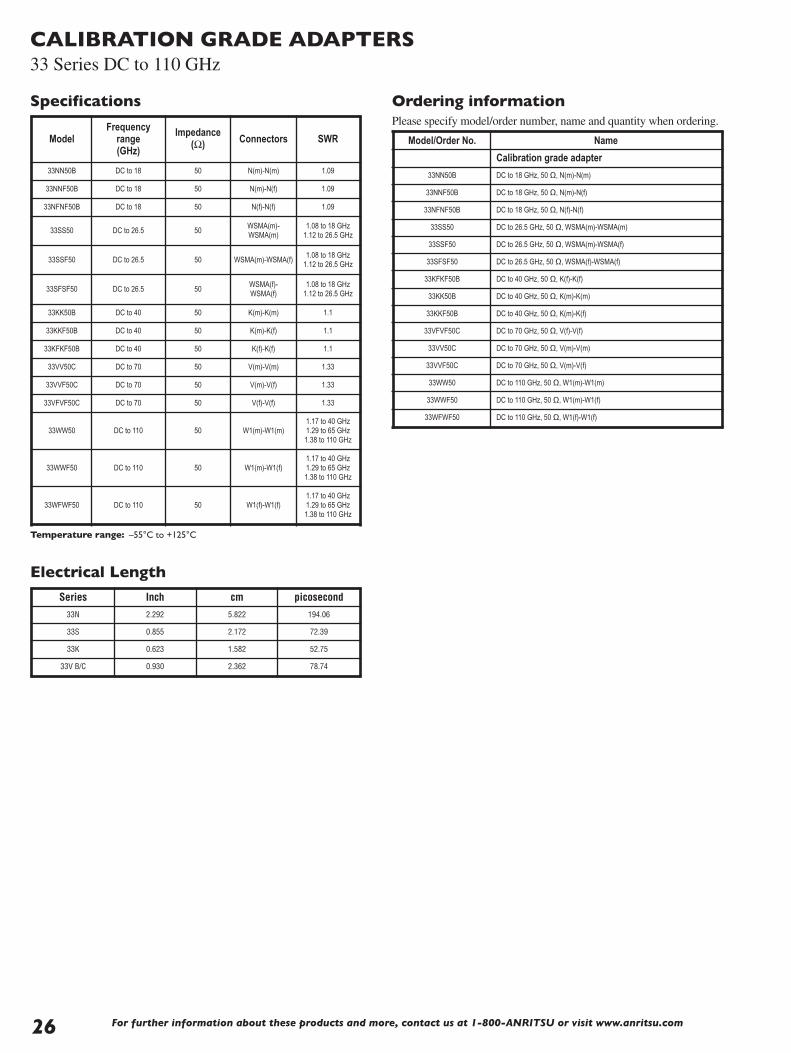
For further information about these products and more, contact us at 1-800-ANRITSU or visit www.anritsu.com26
CALIBRATION GRADE ADAPTERS33 Series DC to 110 GHz
Temperature range: –55°C to +125°C
ModelFrequency
range (GHz)
Impedance(Ω) Connectors SWR
33NN50B DC to 18 50 N(m)-N(m) 1.09
33NNF50B DC to 18 50 N(m)-N(f) 1.09
33NFNF50B DC to 18 50 N(f)-N(f) 1.09
33SS50 DC to 26.5 50WSMA(m)-WSMA(m)
1.08 to 18 GHz1.12 to 26.5 GHz
33SSF50 DC to 26.5 50 WSMA(m)-WSMA(f)1.08 to 18 GHz
1.12 to 26.5 GHz
33SFSF50 DC to 26.5 50WSMA(f)-WSMA(f)
1.08 to 18 GHz1.12 to 26.5 GHz
33KK50B DC to 40 50 K(m)-K(m) 1.1
33KKF50B DC to 40 50 K(m)-K(f) 1.1
33KFKF50B DC to 40 50 K(f)-K(f) 1.1
33VV50C DC to 70 50 V(m)-V(m) 1.33
33VVF50C DC to 70 50 V(m)-V(f) 1.33
33VFVF50C DC to 70 50 V(f)-V(f) 1.33
33WW50 DC to 110 50 W1(m)-W1(m)1.17 to 40 GHz1.29 to 65 GHz1.38 to 110 GHz
33WWF50 DC to 110 50 W1(m)-W1(f)1.17 to 40 GHz1.29 to 65 GHz1.38 to 110 GHz
33WFWF50 DC to 110 50 W1(f)-W1(f)1.17 to 40 GHz1.29 to 65 GHz1.38 to 110 GHz
Ordering informationPlease specify model/order number, name and quantity when ordering.
Model/Order No. Name
Calibration grade adapter
33NN50B DC to 18 GHz, 50 Ω, N(m)-N(m)
33NNF50B DC to 18 GHz, 50 Ω, N(m)-N(f)
33NFNF50B DC to 18 GHz, 50 Ω, N(f)-N(f)
33SS50 DC to 26.5 GHz, 50 Ω, WSMA(m)-WSMA(m)
33SSF50 DC to 26.5 GHz, 50 Ω, WSMA(m)-WSMA(f)
33SFSF50 DC to 26.5 GHz, 50 Ω, WSMA(f)-WSMA(f)
33KFKF50B DC to 40 GHz, 50 Ω, K(f)-K(f)
33KK50B DC to 40 GHz, 50 Ω, K(m)-K(m)
33KKF50B DC to 40 GHz, 50 Ω, K(m)-K(f)
33VFVF50C DC to 70 GHz, 50 Ω, V(f)-V(f)
33VV50C DC to 70 GHz, 50 Ω, V(m)-V(m)
33VVF50C DC to 70 GHz, 50 Ω, V(m)-V(f)
33WW50 DC to 110 GHz, 50 Ω, W1(m)-W1(m)
33WWF50 DC to 110 GHz, 50 Ω, W1(m)-W1(f)
33WFWF50 DC to 110 GHz, 50 Ω, W1(f)-W1(f)
Specifications
Series Inch cm picosecond
33N 2.292 5.822 194.06
33S 0.855 2.172 72.39
33K 0.623 1.582 52.75
33V B/C 0.930 2.362 78.74
Electrical Length

For further information about these products and more, contact us at 1-800-ANRITSU or visit www.anritsu.com 27
INSTRUMENTATION GRADE ADAPTERS34 Series DC to 60 GHz
The 34 Series of precision adapters enable accurate measurementswith GPC-7, Type N, or WSMA interfaces. Every adapter is fullyspecified and 100% tested to ensure low reflections and optimumperformance over a broad frequency range.
Precision adapter features• Low SWR and insertion loss• GPC-7, Type N, and WSMA connectors• Convenient transition with minimal effect on signal• 50 Ω or 75 Ω impedance
Specifications
34RSN50
34RKRK5034ASF50
34NN50A
ModelFrequency
range(GHz)
Impedance(Ω) Connectors SWR Dimensions
L(cm) x dia(cm)
34NN75B DC to 3 75 N(m) to N(m) 1.1 6.0 x 2.2
34AN5034ANF50
DC to 18 50GPC-7 to N(m)GPC-7 to N(f)
1.024.2 x 2.24.2 x 2.2
34AS5034ASF50
DC to 18 50
GPC-7 toWSMA(m)GPC-7 toWSMA(f)
1.0333.8 x 2.23.8 x 2.2
34NN50A34NFNF50
DC to 18 50N(m) to N(m)N(f) to N(f)
1.16.0 x 2.24.7 x 1.6
34NK5034NKF5034NFK5034NFKF50
DC to 18 50
N(m) to K(m)N(m) to K(f)N(f) to K(m)N(f) to K(f)
1.12
3.8 x 2.23.8 x 2.23.8 x 1.63.8 x 1.6
34SFSF50 DC to 26.5 50WSMA(f) to
WSMA(f)
1.11 to18.5 GHz
1.18 to26.5 GHz
1.6 x 0.8
Model Frequencyrange (GHz) Connectors SWR Dimensions
L(cm) x dia(cm)
34RSN50 DC to 18 RS(m) to N(m) 1.40 5.1 x 2.2
34RKNF50 DC to 18 RK(m) to N(f) 1.40 5.1 x 1.7
34RVNF50 DC to 18 RV(m) to N(f) 1.40 5.1 x 1.7
34RKRK50 DC to 40 RK(m) to RK(m) 2.00 5.8 x 1.7
34RVRK50 DC to 40 RV(m) to RK(m) 2.00 5.8 x 1.7
34RVRV50 DC to 60 RV(m) to RV(m) 2.30 5.8 x 1.7
Impedance: 50 ΩTemperature range: 0°C to +75°C
Anritsu Instrument Connector
34R Series Adapter
Ordering informationPlease specify model/order number, name, and quantity when ordering.
Model/Order No. Name
Precision adapter34NN75B DC to 3 GHz, 75 Ω, N(m)-N(m)
34AN50 DC to 18 GHz, 50 Ω, GPC-7-N(m)
34ANF50 DC to 18 GHz, 50 Ω, GPC-7-N(f)
34AS50 DC to 18 GHz, 50 Ω, GPC-7-WSMA(m)
34ASF50 DC to 18 GHz, 50 Ω, GPC-7-WSMA(f)
34NN50A DC to 18 GHz, 50 Ω, N(m)-N(m)
34NFNF50 DC to 18 GHz, 50 Ω, N (f)-N(f)
34NK50 DC to 18 GHz, 50 Ω, N (m)-K(m)
34NKF50 DC to 18 GHz, 50 Ω, N(m)-K(f)
34NFK50 DC to 18 GHz, 50 Ω, N (f)-K(m)
34NFKF50 DC to 18 GHz, 50 Ω, N(f)-K(f)
34SFSF50 DC to 26.5 GHz, 50 Ω, WSMA(f)-WSMA(f)
34RSN50 DC to 18 GHz, 50 Ω, RS(m) to N(m)
34RKNF50 DC to 18 GHz, 50 Ω, RK(m) to N(f)
34RVNF50 DC to 18 GHz, 50 Ω, RV(m) to N(f)
34RKRK50 DC to 40 GHz, 50 Ω, RK(m) to RK(m)
34RVRK50 DC to 40 GHz, 50 Ω, RV(m) to RK(m)
34RVRV50 DC to 60 GHz, 50 Ω, RV(m) to RV(m)
Specifications
The 34R Series precision adapters provide a rugged, rigid connectionbetween Anritsu instruments with WSMA, K Connector®, or V Connector® outputs and Anritsu SWR Autotesters and SWR Bridgesor other instruments.
The adapters have an outside diameter equal to that of a Type Nconnector, adding mechanical strength to the test setup and makinginstallation convenient and fast.
Ruggedized adapter features• Enhance reliability of microwave test setup• Easy-to-grasp Type N outside diameter• Rigid test connections for improved test data repeatability

For further information about these products and more, contact us at 1-800-ANRITSU or visit www.anritsu.com28
INSTRUMENTATION GRADE ADAPTERS34 Series W to V DC to 65 GHz
34WVF50
34WFVF50
These 34 Series of precision adapters enable accurate measurementwith W1 Connector® and V Connector® interfaces.
Precision adapter features• Low SWR and insertion loss• W1 and V Connectors®• 50 Ω Impedance
Specifications
Ordering informationPlease specify model/order number, name, and quantity when ordering.
23.98
11.696.96
7.92 HEX
6.00 HEX
Dimensions in millimeters
34WV50 outline
21.88
11.70 4.85
7.92 HEX
M4 X .7-6G
Dimensions in millimeters
34WFV50 outline
19.90
7.62 6.94
M7 X .75-6G 7.92 HEX
6.00 HEX
Dimensions in millimeters
34WVF50 outline
17.82
7.63 4.85
M7 X .75-6G7.92 HEX
M4 X .7-6G
Dimensions in millimeters
34WFVF50 outline
ModelFrequency
Range (GHz)
Impedance(Ω) Connectors Insertion
Loss SWR
34WV50 DC to 65 GHz 50 W1(m) to V(m) 0.5 dB 1.22
34WFV50 DC to 65 GHz 50 W1(f) to V(m) 0.5 dB 1.22
34WVF50 DC to 65 GHz 50 W1(m) to V(f) 0.5 dB 1.22
34WFVF50 DC to 65 GHz 50 W1(f) to V(f) 0.5 dB 1.22
Model/Order No. Name
Precision adapter
34WV50 DC to 65 GHz, 50 Ω, W1(m) to V(m)
34WFV50 DC to 65 GHz, 50 Ω, W1(f) to V(m)
34WVF50 DC to 65 GHz, 50 Ω, W1(m) to V(f)
34WFVF50 DC to 65 GHz, 50 Ω, W1(f) to V(f)

For further information about these products and more, contact us at 1-800-ANRITSU or visit www.anritsu.com 29
INSTRUMENTATION GRADE WAVEGUIDE ADAPTERS35WR Series 18 to 110 GHz
35WR42K 35WR19K
35WR22V 35WR19V
The 35 Series precision adapters transform standard or double-ridgewaveguide to coaxial K Connector® and V Connector®, and W1Connector®, interfaces, thus enabling convenient millimeter wavecoaxial measurements.
Features• 18 to 65 GHz frequency coverage• K Connector® compatibility with SMA and 3.5 mm• V Connector® compatibility with 2.4 mm• W1 Connector® compatibility with 1.0 mm• Standard and double-ridge designs
Specifications
Ordering informationPlease specify model/order number, name, and quantity when ordering.
Model Frequencyrange (GHz) Connectors W/G flange SWR
35WRD180K35WRD180KF
18 to 40WRD180 to K(m)WRD180 to K(f)
N/A 1.25
35WR42K35WR42KF
18 to 26.5WR42 to K(m)WR42 to K(f)
595 1.25
35WR28K35WR28KF
26.5 to 40WR28 to K(m)WR28 to K(f)
599 1.25
35WR22K35WR22KF
33 to 50WR22 to K(m)WR22 to K(f)
383 1.30
35WR22V35WR22VF
33 to 50WR22 to V(m)WR22 to V(f)
383 1.30
35WR19K35WR19KF
40 to 50Usable to 54
WR19 to K(m)WR19 to K(f)
383 1.30
35WR19V35WR19VF
40 to 60WR19 to V(m)WR19 to V(f)
383 1.30
35WR15V35WR15VF
50 to 65WR15 to V(m)WR15 to V(f)
385 1.30
35WR10W35WR10WF
75 to 110WR10 to W(m)WR10 to W(f)
387 1.38
Model/Order No. Name
Precision waveguide to coax adapter
35WRD180K 18 to 40 GHz, WRD180 (double ridge waveguide) to K(m)
35WRD180KF 18 to 40 GHz, WRD180 (double ridge waveguide) to K(f)
35WR42K 18 to 26.5 GHz, WR42-K(m)
35WR42KF 18 to 26.5 GHz, WR42-K(f)
35WR28K 26.5 to 40 GHz, WR28-K(m)
35WR28KF 26.5 to 40 GHz, WR28-K(f)
35WR22K 33 to 50 GHz, WR22-K(m)
35WR22KF 33 to 50 GHz, WR22-K(f)
35WR22V 33 to 50 GHz, WR22-V(m)
35WR22VF 33 to 50 GHz, WR22-V(f)
35WR19K 40 to 50 GHz (usable to 54 GHz), WR19-K(m)
35WR19KF 40 to 50 GHz (usable to 54 GHz), WR19-K(f)
35WR19V 40 to 60 GHz, WR19-V(m)
35WR19VF 40 to 60 GHz, WR19-V(f)
35WR15V 50 to 65 GHz (usable to 67 GHz), WR15-V(m)
35WR15VF 50 to 65 GHz (usable to 67 GHz), WR15-V(f)
35WR10W 75 to 110, WR10 to W(m)
35WR10WF 75 to 110, WR10 to W(f)
Outline drawings for the 35 Series Waveguide-to-Coaxial Adapters,18 to 110 GHz, are shown on the following three pages.
Impedance: 50 ΩTemperature range: –55°C to +125°C
35WR10W
35WR10WF

For further information about these products and more, contact us at 1-800-ANRITSU or visit www.anritsu.com30
INSTRUMENTATION GRADE WAVEGUIDE ADAPTERS35WR Series 18 to 110 GHz
Outline Drawings
B
CA
ED
ALIGNMENT PIN2 PLACES(WR180 ONLY)
MALE OR FEMALE, K CONNECTOR
4.37
4.77 TYPICAL
2.95 DIA. THRU4 PLACES
35WR42K, 35WR42KF
4.31 17.0 22.23 SQ.
16.26
10.67
ALIGNMENT PIN2 PLACES2.44 DIA. THRU
2 PLACES
35WRD180K, 35WRD180KF
7.927.92
7.311.83
1.45
3.40 14.22 22.23 SQ.
7.11
4-40 UNC-2B2 PLACES
35WR28K, 35WR28KF
2.95 DIA. THRU4 PLACES
19.05 SQ.13.463.56
7.11
12.7 Dimension in millimeters
Dimension in millimeters
Dimension in millimeters
35WRD180K, 35WRD180KF, 35WR42K, 35WR42KF, 35WR28K, 35WR28KF outlines
Model Dimensions (mm)
A B C D E
35WRD180K 13.20 27.9 14.43 28.40 23.80
35WRD180KF 13.20 22.9 14.43 28.40 23.80
35WR42K 13.20 27.9 14.43 28.14 23.93
35WR42KF 13.20 22.9 14.43 28.14 23.93
35WR28K 10.67 27.9 14.86 28.78 23.93
35WR28KF 10.67 22.9 14.86 28.78 23.88

For further information about these products and more, contact us at 1-800-ANRITSU or visit www.anritsu.com 31
INSTRUMENTATION GRADE WAVEGUIDE ADAPTERS35WR Series 18 to 110 GHz
Outline Drawings
ALIGNMENT PIN2 PLACES
2.46 DIA. THRU2 PLACES
35WR22K, 35WR22KF, 35WR22V, 35WR22VF
28.57 DIA.2.84
23.82 DIA.
5.69
2.46 DIA. THRU2 PLACES
ALIGNMENT PIN2 PLACES
35WR19K, 35WR19KF, 35WR19V, 35WR19VF
28.57 DIA.
23.82 DIA.
2.39
4.77
ED
B
CA
MALE OR FEMALE, K OR V CONNECTOR
ALIGNMENT PIN2 PLACES
3.96
ALIGNMENT PIN2 PLACES
1.7 DIA. THRU2 PLACES
35WR15V, 35WR15VF
19.05 DIA.
14.3 DIA.
1.88
3.76
Dimension in millimeters
Dimension in millimeters
Dimension in millimeters
35WR22K, 35WR22KF, 35WR22V, 35WR22VF, 35WR19K, 35WR19KF, 35WR19V, 35WR19VF, 35WR15V, and 35WR15VF outlines
Model Dimensions (mm)
A B C D E
35WR22K 12.70 26.9 14.73 25.76 21.44
35WR22KF 12.70 21.6 14.73 25.76 21.44
35WR22V 12.70 26.9 14.73 25.76 21.44
35WR22VF 12.70 21.6 14.73 25.76 21.44
35WR19K 12.70 26.9 14.73 25.76 21.44
35WR19KF 12.70 21.6 14.73 25.76 21.44
35WR19V 12.70 27.9 14.73 25.76 21.44
35WR19VF 12.70 22.6 14.73 25.76 21.44
35WR15V 12.70 24.4 12.19 26.97 21.62
35WR15VF 12.70 20.3 12.19 26.97 21.62

For further information about these products and more, contact us at 1-800-ANRITSU or visit www.anritsu.com32
INSTRUMENTATION GRADE WAVEGUIDE ADAPTERS35WR Series 18 to 110 GHz
Outline Drawings
Ø19.05
2X 4.0
30.62
23.03
18.00
11.00
Ø8.00
ALIGNMENT PINS Dimensions in millimeters
35WR10W outline
Ø19.05
ALIGNMENT PINS
30.62
23.03
16.5611.0
Ø8.00
2X 4.0
Dimensions in millimeters
35WR10WF outline

For further information about these products and more, contact us at 1-800-ANRITSU or visit www.anritsu.com 33
INSTRUMENTATION GRADE WAVEGUIDE ADAPTERS 35U, 35C Series 3.3 to 26.5 GHz
35UM40N
35UM84N
35UA187N
The 35U and 35C Series precision adapters transform standardwaveguide to coaxial Type N and K Connector® interfaces.
Features• 3.3 to 26.5 GHz frequency coverage• Type N connector compatibility• K Connector® compatibility with SMA and 3.5 mm
Specifications
35UA42K
Model Frequencyrange (GHz) Connectors W/G flange SWR
35UM40N 3.3 to 4.9WR229 to N(m) WG11A to N(m)
PDR40 1.08
35UM48N 3.9 to 5.8WR187 to N(m) WG12 to N(m)
CAR48, PAR48, UAR48, PDR48
1.08
35UM70N 5.8 to 8.2WR137 to N(m) WG14 to N(m)
CAR70, PAR70, UAR70, PDR70
1.08
35UM84N 7.0 to 10WR112 to N(m) WG15 to N(m)
CBR84, UBR84, PBR84, PDR84
1.08
35UM100N 8.2 to 12.4WR90 to N(m) WG16 to N(m)
CBR100, UBR100, PBR100, PDR100
1.08
35UM120N 10 to 15WR75 to N(m) WG17 to N(m)
CBR120, UBR120, PBR120, PDR120
1.08
35UM140N 12.4 to 18WR62 to N(m) WG18 to N(m)
CBR140, UBR140, PBR140, PDR140
1.08
35UM220K 17 to 26.5WR42 to K(m) WG20 to K(m)
CBR220, UBR220, PBR220, PDR220
1.20
35UA187N 3.9 to 5.8WR187 to N(m) WG12 to N(m)
CPR187F, CPR187G, UG-1352/U, UG-1353/U, UG-1728/U, UG-1729/U, UG-148/U, UG-149A/U
1.08
Model Frequencyrange (GHz) Connectors W/G flange SWR
35UA137N 5.8 to 8.2WR137 to N(m) WG14 to N(m)
CPR137F, CPR137G, UG-1356/U, UG-1357/U, UG-1732/U, UG-1733/U, UG-343B/U, UG-344/U, UG-440B/U, UG-441/U
1.08
35UA112N 7.0 to 10WR112 to N(m) WG15 to N(m)
CPR112F, CPR112G, UG-1358/U, UG-1359/U, UG-1734/U, UG-1735/U,
UG-52B/U, UG-51/U, UG-137B/U, UG-138/U
1.08
35UA90N 8.2 to 12.4WR90 to N(m) WG16 to N(m)
CPR90F, CPR90G, UG-1360/U, UG-1361/U, UG-1736/U, UG-1737/U,
UG-40B/U, UG-39/U, UG-135B/U, UG-136/U
1.08
35UA62N 12.4 to 18WR62 to N(m) WG18 to N(m)
UG-541A/U, UG-419A/U UG-1665/U, UG-1666/U
1.08
35UA42K 17 to 26.5WR42 to K(m) WG20 to K(m)
UG-596A/U, UG-595/U, UG-597/U, UG-598A/U
1.08
Specifications

For further information about these products and more, contact us at 1-800-ANRITSU or visit www.anritsu.com34
INSTRUMENTATION GRADE WAVEGUIDE ADAPTERS35U, 35C Series 3.3 to 26.5 GHz
M610 PLACES
35UM40N
82.30 ± 0.05
4.76 DIA.2 PLACES
+0.01–0.00
Dimensions in millimeters
CONNECTOR
43.7
55.88 ± 0.7676.2 ± 0.76
35UM40N outline
M514 PLACES
36.52 ± 0.05
35UM70N
CONNECTOR
34.5
50.8 ± 0.76 67.31 ± 0.76
Dimensions in millimeters
3.19 DIA. +0.012 PLACES –0.00
35UM70N outline
M410 PLACES
28.50 ± 0.05
35UM120N
CONNECTOR
30.5
43.18 ± 0.76
55.88 ± 0.76
3.19 DIA.2 PLACES
+0.01–0.00
Dimensions in millimeters
35UM120N outline
M58 PLACESM68 PLACES
46.43 ± 0.05
35UM48N
4.76 DIA.2 PLACES
+0.01–0.00
Dimensions in millimeters
CONNECTOR
39.6
59.69 ± 0.76 81.28 ± 0.76
35UM48N outline
M412 PLACES
37.43 ±0.05
35UM84N
CONNECTOR
32.0
45.72 ± 0.76
63.5 ± 0.76
Dimensions in millimeters
3.19 DIA. +0.012 PLACES –0.00
35UM84N outline
M44 PLACES
24.28 ± 0.05
35UM140N
CONNECTOR
29.7
43.18 ± 0.76
55.88 ± 0.76
3.19 DIA.2 PLACES
+0.01–0.00
Dimensions in millimeters
35UM140N outline
#10-328 PLACES
35UA187N
46.43 ± 0.05
#1/4-208 PLACESDimensions in millimeters
4.76 DIA.2 PLACES
+0.01–0.00
39.6
59.69 ± 0.76
81.28 ± 0.76
CONNECTOR
35UA187N outline
M412 PLACES
32.5 ± 0.05
35UM100N
CONNECTOR
30.7
43.18 ± 0.76
55.88 ± 0.76
Dimensions in millimeters
3.19 DIA. +0.012 PLACES –0.00
35UM100N outline
M34 PLACES
17.01 ± 0.05
35UM220K
CONNECTOR
19.8
30.48 ± 0.76
38.1 ± 0.76
2.38 DIA.2 PLACES
+0.01–0.00
Dimensions in millimeters
35UM220K outline
Outline Drawings

For further information about these products and more, contact us at 1-800-ANRITSU or visit www.anritsu.com 35
INSTRUMENTATION GRADE WAVEGUIDE ADAPTERS35U, 35C Series 3.3 to 26.5 GHz
CONNECTOR
34.5
50.8 ± 0.76
67.31± 0.76
Dimensions in millimeters
#10-3214 PLACES
35UA137N
36.52 ± 0.05
3.19 DIA. +0.012 PLACES −0.00
35UA137N outline
CONNECTOR
45.72 ± 0.76
32.0
Dimensions in millimeters
37.44 ± 0.05
#8-3212 PLACES
35UA112N
63.5 ± 0.76
3.19 DIA. +0.012 PLACES −0.00
35UA112N outline
CONNECTOR
29.7
43.18 ± 0.76
55.88 ± 0.76
#6-324 PLACES
24.28 ± 0.05
35UA62N
Dimensions in millimeters
3.19 DIA. +0.012 PLACES −0.00
35UA62N outline
CONNECTOR
43.18 ± 0.76
55.88 ± 0.76
Dimensions in millimeters
#8-3212 PLACES
32.51 ± 0.05
35UA90N
30.7
3.19 DIA. +0.012 PLACES −0.00
35UA90N outline
CONNECTOR
19.8
30.48 ±0.76
38.1 ± 0.76
Dimensions in millimeters
#4-404 PLACES
17.01 ± 0.05
35UA42K
2.38 DIA. +0.002 PLACES −0.00
35UA42K outline
Outline Drawings
Ordering informationPlease specify model/order number, name, and quantity when ordering.
Model/Order No. Name
Coaxial adapter
35UM40N N(m), metric, 3.30 to 4.90 GHz
35UM48N N(m), metric, 3.95 to 5.85 GHz
35UM70N N(m), metric, 5.85 to 8.20 GHz
35UM84N N(m), metric, 7.05 to 10.00 GHz
35UM100N N(m), metric, 8.20 to 12.40 GHz
35UM120N N(m), metric, 10.00 to 15.00 GHz
35UM140N N(m), metric, 12.40 to 18.0 GHz
Model/Order No. Name
Coaxial adapter
35UM220K K(m), metric, 17.00 to 26.5 GHz
35UA187N N(m), US, 3.95 to 5.85 GHz
35UA137N N(m), US, 5.85 to 8.20 GHz
35UA112N N(m), US, 7.05 to 10.00 GHz
35UA90N N(m), US, 8.20 to 12.40 GHz
35UA62N N(m), US, 12.40 to 18.0 GHz
35UA42K K(m), US, 17.00 to 26.5 GHz

For further information about these products and more, contact us at 1-800-ANRITSU or visit www.anritsu.com36
COAXIAL TERMINATIONS28, 29 Series DC to 110 GHz
29A50-20
28KF50A
28N50-228V50C
28K50A
28W50
These precision, metrology-grade terminations are used inmeasurement systems that need to achieve the smallest possiblereflections. Their excellent match makes them ideal as a referencefor fault location measurements on scalar network analyzers.
Precision termination features• Accurate reference for SWR measurements• Precise termination for test instrument or device under test
Precision termination specificationsOrdering informationPlease specify model/order number, name, and quantity when ordering.
Offset termination specifications
Temperature range: +25°C ±5°C
Model Frequencyrange (GHz)
Test portconnector
Inputimpedance
(Ω)
SWR (F in GHz)
DimensionsL(cm) xdia(cm)
28A50-1 DC to 18 GPC-7 50 1.02 Max. 5.2 x 2.2
28N50-228NF50-2
DC to 18N(m)N(f)
50 1.02 Max.5.2 x 2.24.8 x 1.6
28N50-3 DC to 8 N(m) 50 1.03 Max. 5.2 x 2.2
28S50-128SF50-1
DC to 26.5WSMA(m)WSMA(f)
501.020 to 18.5 GHz1.153 to 26.5 GHz
3.7 x 1.23.7 x 1.2
28K50A28KF50A
DC to 40K(m)K(f)
501.040 to 20 GHz1.052 to 40 GHz
3.7 x 1.23.7 x 1.2
28V50C28VF50C
DC to 67V(m)V(f)
50
1.018 to 6 GHz1.030 to 20 GHz1.050 to 50 GHz1.080 to 65 GHz1.100 to 67 GHz
3.7 x 1.23.7 x 1.2
28W50 DC to 110 W1(m) 501.046 to 20 GHz1.058 to 65 GHz1.330 to 110 GHz
2.5 x 0.8
28WF50 DC to 110 W1(f) 501.052 to 20 GHz1.066 to 65 GHz1.500 to 110 GHz
2.5 x 0.8
Model Frequency
range (GHz)
Test port connector
Return loss (dB)
DimensionsL(cm) xdia(cm)
29A50-20 DC to 18 GPC-720 ±0.5 to 1 GHz20 ±1.0 to 4 GHz
20 ±1.5 to 18 GHz5.2 x 2.2
29S50-20 DC to 26.5 WSMA(m)20 ±1.5 to 18.5 GHz20 ±2.5 to 26.5 GHz
3.7 x 1.2
Model/Order No. Name
Precision termination
28A50-1 DC to 18 GHz, 50 Ω, GPC-7
28N50-2 DC to 18 GHz, 40 dB, 50 Ω, N(m)
28NF50-2 DC to 18 GHz, 40 dB, 50 Ω, N(f)
28N50-3 DC to 8.6 GHz, 50 Ω, N(m)
28S50-1 DC to 26.5 GHz, 50 Ω, WSMA(m) (selected for higher accuracy)
28SF50-1 DC to 26.5 GHz, 50 Ω, WSMA(f) (selected for higher accuracy)
28K50 DC to 40 GHz, 50 Ω, K(m)
28KF50 DC to 40 GHz, 50 Ω, K(f)
28V50C DC to 67 GHz, V(m)
28VF50C DC to 67 GHz, V(f)
28W50 DC to 110 GHz, 50 Ω, W1(m)
28WF50 DC to 110 GHz, 50 Ω, W1(f)
Offset termination
29A50-20 DC to 18 GHz, 50 Ω, GPC-7, 20 dB return loss
29S50-20 DC to 26.5 GHz, 50 Ω, WSMA(m), 20 dB return loss
29SF50-20 DC to 26.5 GHz, 50 Ω, WSMA(f), 20 dB return loss
29K50-15 DC to 40 GHz, 50 Ω, K(m), 15 dB return loss
29KF50-15 DC to 40 GHz, 50 Ω, K(f), 15 dB return loss
Maximum Input Power: 0.5 W
When used with Anritsu airlines, the 29 Series Offset Terminationspermit measurements down to 1.006 SWR to 18 GHz, 1.01 SWRto 26.5 GHz, and 1.02 SWR to 40 GHz.
Offset termination features• 50 Ω Offset Terminations for precise measurement
of low SWR or high directivity• Measurements down to 1.006 SWR to 18 GHz,
1.01 SWR to 26.5 GHz, and 1.02 SWR to 40 GHz
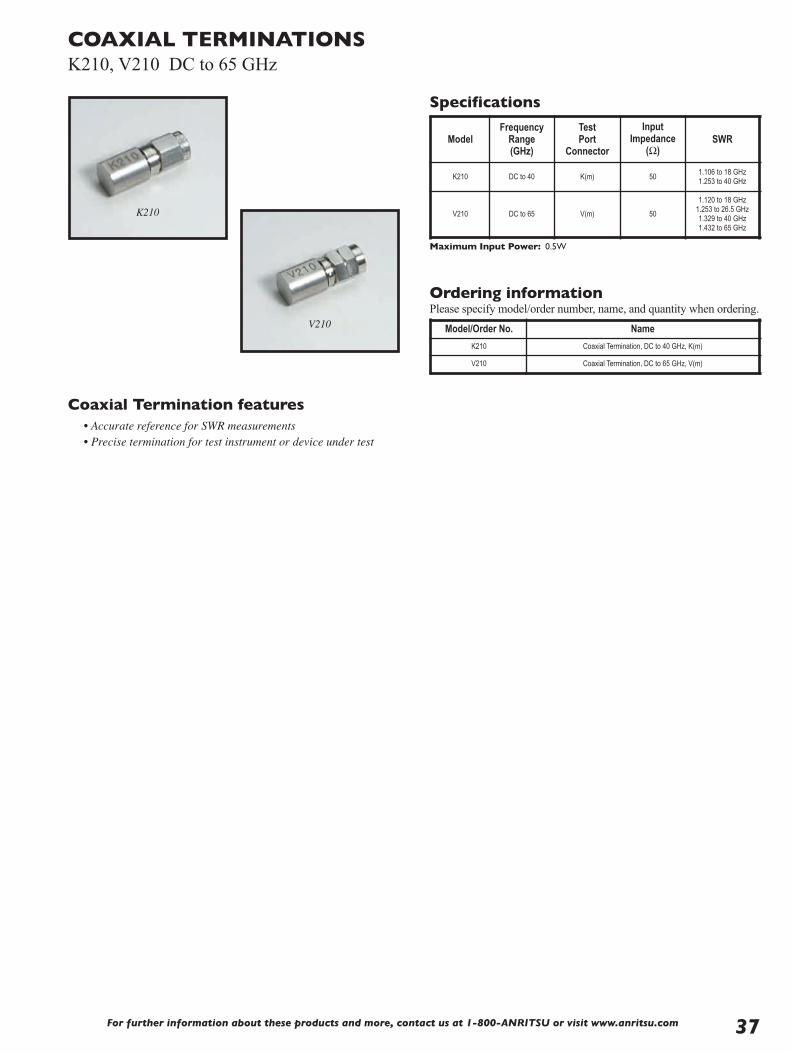
For further information about these products and more, contact us at 1-800-ANRITSU or visit www.anritsu.com 37
COAXIAL TERMINATIONSK210, V210 DC to 65 GHz
K210
V210
Coaxial Termination features• Accurate reference for SWR measurements• Precise termination for test instrument or device under test
Specifications
Ordering informationPlease specify model/order number, name, and quantity when ordering.
Maximum Input Power: 0.5W
Model Frequency
Range (GHz)
Test Port
Connector
Input Impedance
(Ω)SWR
K210 DC to 40 K(m) 50 1.106 to 18 GHz1.253 to 40 GHz
V210 DC to 65 V(m) 50
1.120 to 18 GHz1.253 to 26.5 GHz1.329 to 40 GHz1.432 to 65 GHz
Model/Order No. Name
K210 Coaxial Termination, DC to 40 GHz, K(m)
V210 Coaxial Termination, DC to 65 GHz, V(m)
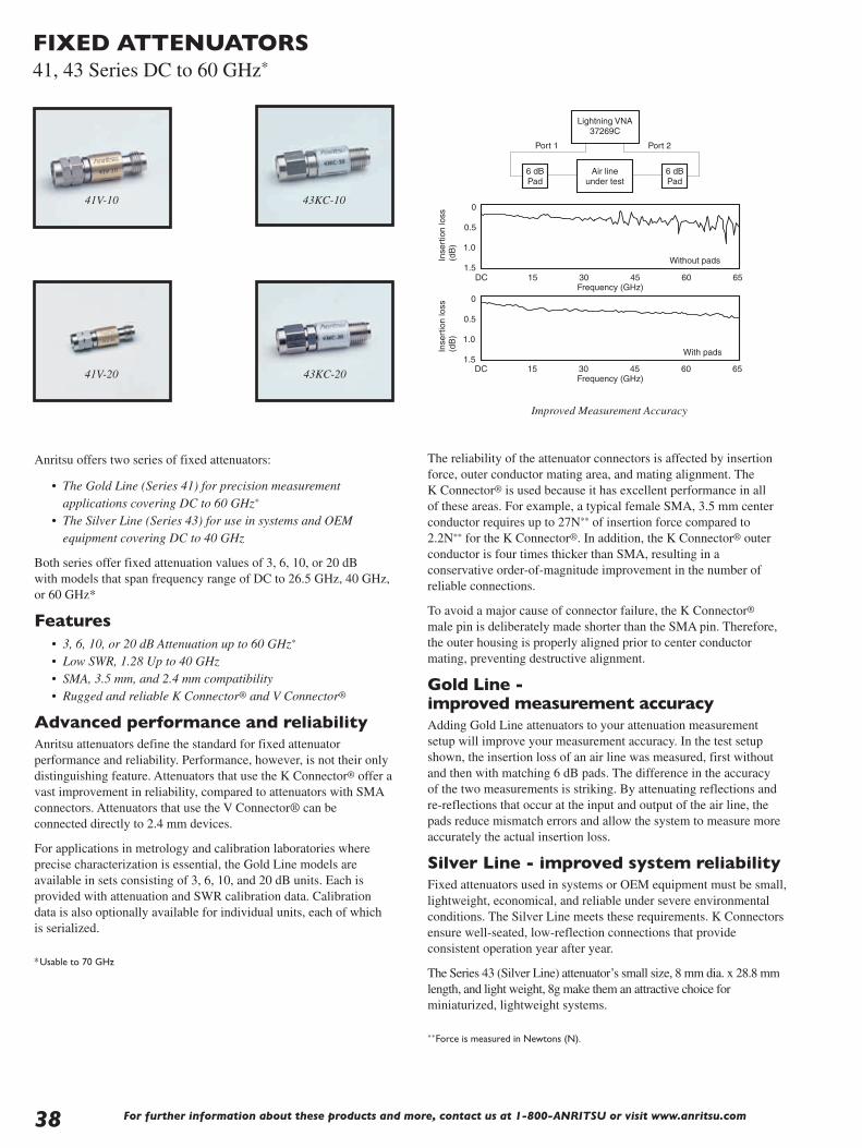
For further information about these products and more, contact us at 1-800-ANRITSU or visit www.anritsu.com38
Frequency (GHz)
0
0.5
1.0
1.5
0
0.5
1.0
1.5DC 15 30 45 60 65
Frequency (GHz)DC 15 30 45 60 65
Without pads
With pads
Inse
rtio
nlo
ss(d
B)
Inse
rtio
nlo
ss(d
B)
Air line under test
6 dB Pad
6 dB Pad
Lightning VNA 37269C
Port 1 Port 2
FIXED ATTENUATORS41, 43 Series DC to 60 GHz*
Anritsu offers two series of fixed attenuators:
• The Gold Line (Series 41) for precision measurementapplications covering DC to 60 GHz*
• The Silver Line (Series 43) for use in systems and OEMequipment covering DC to 40 GHz
Both series offer fixed attenuation values of 3, 6, 10, or 20 dBwith models that span frequency range of DC to 26.5 GHz, 40 GHz,or 60 GHz*
Features• 3, 6, 10, or 20 dB Attenuation up to 60 GHz*
• Low SWR, 1.28 Up to 40 GHz• SMA, 3.5 mm, and 2.4 mm compatibility• Rugged and reliable K Connector® and V Connector®
Advanced performance and reliabilityAnritsu attenuators define the standard for fixed attenuatorperformance and reliability. Performance, however, is not their onlydistinguishing feature. Attenuators that use the K Connector® offer avast improvement in reliability, compared to attenuators with SMAconnectors. Attenuators that use the V Connector® can beconnected directly to 2.4 mm devices.
For applications in metrology and calibration laboratories whereprecise characterization is essential, the Gold Line models areavailable in sets consisting of 3, 6, 10, and 20 dB units. Each isprovided with attenuation and SWR calibration data. Calibrationdata is also optionally available for individual units, each of whichis serialized.
*Usable to 70 GHz
The reliability of the attenuator connectors is affected by insertionforce, outer conductor mating area, and mating alignment. TheK Connector® is used because it has excellent performance in allof these areas. For example, a typical female SMA, 3.5 mm centerconductor requires up to 27N** of insertion force compared to2.2N** for the K Connector®. In addition, the K Connector® outerconductor is four times thicker than SMA, resulting in aconservative order-of-magnitude improvement in the number ofreliable connections.
To avoid a major cause of connector failure, the K Connector®
male pin is deliberately made shorter than the SMA pin. Therefore,the outer housing is properly aligned prior to center conductormating, preventing destructive alignment.
Gold Line -improved measurement accuracyAdding Gold Line attenuators to your attenuation measurementsetup will improve your measurement accuracy. In the test setupshown, the insertion loss of an air line was measured, first withoutand then with matching 6 dB pads. The difference in the accuracyof the two measurements is striking. By attenuating reflections andre-reflections that occur at the input and output of the air line, thepads reduce mismatch errors and allow the system to measure moreaccurately the actual insertion loss.
Silver Line - improved system reliabilityFixed attenuators used in systems or OEM equipment must be small,lightweight, economical, and reliable under severe environmentalconditions. The Silver Line meets these requirements. K Connectorsensure well-seated, low-reflection connections that provideconsistent operation year after year.
The Series 43 (Silver Line) attenuator’s small size, 8 mm dia. x 28.8 mmlength, and light weight, 8g make them an attractive choice forminiaturized, lightweight systems.
**Force is measured in Newtons (N).
Improved Measurement Accuracy
41V-10 43KC-10
41V-20 43KC-20

FIXED ATTENUATORS41, 43 Series DC to 65 GHz
➀ For traceability, all Gold Line attenuators are serialized.➁ ±1 dB from DC to 26.5 GHz; ±1.3 dB from >26.5 to 40 GHz, including frequency response and DC offset.
Ordering informationPlease specify model/order number, name, and quantity when ordering.Single fixed attenuators may be ordered from the table above.
* A set of 3, 6, 10, and 20 dB Gold line (Series 41).Attenuators are supplied in ahandsome hardwood case. Calibration data are included for each unit.
** Attenuation and SWR test data are provided for input and output ports at 500 MHz frequency intervals.
Common specifications
Specifications
Impedance 50 Ω
Power rating (average) 2W at 20°C; 1W at 85°C
Temperature coefficient 0.001 dB/dB/°C
ConnectorsV Connector® Male and female compatible with 2.4 mm
K Connector® Male and female, compatible with SMA and 3.5 mm
Material Passivated stainless steel housing
SizeLength 28.8 mm ±0.5 mm
Diameter 8 mm
Weight 8g
Temperature rangeOperating –55°C to +85°C
Nonoperating –55°C to +125°C
Model/Order No. Name
Precision Fixed Attenuator41KB-3, 6, 10, or 20 3 dB, 6 dB, 10 dB, 20 dB, DC to 26.5 GHz, 50 Ω, K(m)-K(f)
41KC-3, 6, 10, or 20 3 dB, 6 dB, 10 dB, 20 dB, DC to 40 GHz, 50 Ω, K(m)-K(f)
41V-3, 6, 10, or 20 3 dB, 6 dB, 10 dB, 20 dB, DC to 60 GHz, 50 Ω, V(m)-V(f)
Precision Fixed Attenuator Set41KB-S* 41KB Series
41KC-S* 41KC Series
41V-S* 41V Series
Fixed Attenuator43KB-3, 6, 10, or 20 3 dB, 6 dB, 10 dB, 20 dB, DC to 26.5 GHz, 50 Ω, K(m)-K(f)
43KC-3, 6, 10, or 20 3 dB, 6 dB, 10 dB, 20 dB, DC to 40 GHz, 50 Ω, K(m)-K(f)
OptionOption C** Calibration Data
Gol
dLi
ne
Model➀ Attenuation(dB)
Attenuation Accuracy SWR
DC-18 GHz 18-26.5 GHz 26.5-40 GHz 40-65 GHz DC-12 GHz 12-18 GHz 18-26.5 GHz 26.5-40 GHz 40-60 GHz
DC to 60 GHz41V-341V-641V-1041V-20
361020
±0.5±0.5±0.5±0.5
±0.6±0.6±0.6±0.6
±0.9±0.9±0.9±0.9
±1.50±1.50±1.50±1.50
1.151.151.151.15
1.201.201.201.20
1.301.251.251.25
1.501.401.401.40
1.901.901.901.90
DC to 40 GHz41KC-341KC-641KC-1041KC-20
361020
±0.4±0.4±0.4±0.4
±0.5±0.5±0.5±0.5
±0.8±0.8±0.8±0.8
----
1.101.101.101.10
1.151.151.151.15
1.231.181.181.18
1.421.281.281.28
----
DC to 26.5 GHz41KB-341KB-6
41KB-1041KB-20
361020
±0.4±0.4±0.4±0.4
±0.5±0.5±0.5±0.5
----
----
1.101.101.101.10
1.151.151.151.15
1.231.181.181.18
----
----
Silv
erLi
ne
Model Attenuation➁
(dB)Attenuation Accuracy SWR
DC-18 GHz 18-26.5 GHz 26.5-40 GHz 40-60 GHz DC-12 GHz 12-18 GHz 18-26.5 GHz 26.5-40 GHz 40-60 GHz
DC to 40 GHz43KC-343KC-643KC-1043KC-20
361020
±0.5±0.5±0.5±0.5
±0.6±0.6±0.6±0.6
±0.9±0.9±0.9±0.9
----
1.151.151.151.15
1.201.201.201.20
1.301.301.301.30
1.501.401.401.40
----
DC to 26.5 GHz43KB-343KB-6
43KB-1043KB-20
361020
±0.5±0.5±0.5±0.5
±0.6±0.6±0.6±0.6
----
----
1.151.151.151.15
1.201.201.201.20
1.301.301.301.30
----
----
Environmental informationTests are performed per MIL-STD-202F.
Operating TemperatureRange
–55°C to +85°
Temperature Shock –55°C to +150°
Humidity 95% at 40°C, 96 hours, Test 103B, Condition B
Shock 100 G peak sawtooth, method 213, Condition B
Vibration
Sinewave: 10 Hz to 2000 Hz, 0.06” DA, method 204, test condition D
Random: 50 Hz to 2000 Hz, 11.6 Grms, Power Spectral Density 0.1Grms 2 Hz, Method 214, Test Condition 1, Letter D
Salt Spray 5% concentration for 48 hours, Method 101D, Condition B
Voltage withstanding 500 Vac RMS, 60 seconds, method 301
For further information about these products and more, contact us at 1-800-ANRITSU or visit www.anritsu.com 39

For further information about these products and more, contact us at 1-800-ANRITSU or visit www.anritsu.com40
STEP ATTENUATORS4400, 4500, 4600 Series DC to 40 GHz
Anritsu programmable step attenuators bring a substantial increasein the frequency and attenuation range available in one smallpackage. Using the latest technology, these units offer superiorperformance, reliability, and ease of use to 40 GHz. All are plug-compatible with competitive units.
Features• DC-20 GHz, DC-26.5 GHz, DC-40 GHz• 70 dB and 110 dB attenuation ranges• Low insertion loss• Precise repeatability• Life of 5 million operations• Small, rugged, light weight
Advanced technology-advancedperformanceAnritsu has lowered throughline loss by designing the first 40 dBattenuator sections to operate above 18 GHz. Compared withdesigns that use 30 dB sections, these attenuators have a shorter thrupath and fewer switching contacts. As a result, insertion loss is asmuch as 1.7 dB less than that of units made by other companies. RFinput power requirements for systems that use these attenuators canbe reduced, saving money, space, and weight.
Integrated switching structureThe push rods that switch in the attenuator modules and thrulines aredriven by a solenoid actuator. By designing the solenoid as anintegral part of the attenuator assembly, switching speeds of 20 ms(including settling time) are achieved. Upon completion of theswitching operation, the solenoid is magnetically latched towithstand shock and vibration. At the same time, the solenoidcurrent is automatically turned off to save power and to minimizetemperature rise.
Also integrated in the design is solid state dc switching circuitry thatavoids the relatively high failure rate of mechanical DC switches.Each attenuator section is controlled by its own driver circuit, whichrequires 24V, 125 mA. A typical external driver circuit for onesection is shown in the figure below.
102.9 4422K, 4522K, 4622K76.2 4412K, 4512K, 4612K
7.1
17.8
7.1
17.8
24.4
44.5
14 Pin Dip
XXXX K STEP ATTENUATOR
SN XXXXX MAX POWER1 WATT CW
117 4422K, 4522K, 4622K90.2 4412K, 4512K, 4612K
FemaleConnector
FemaleConnector
5.7 2 Places
7.0
25.4
4-40 UNC-2B
410
Dimensions in millimeters
4400, 4500, and 4600 series outline
4622K4612K
+5 V
+5 V
83
4
5
ControlLine
ControlLine1N4446
75451
1
2
6
6
7
147
9
10
11
TTL Input
75LS04 75LS04
Power+24 V

STEP ATTENUATORS4400, 4500, 4600 Series DC to 40 GHz
Accuracy enhancing calibration dataAttenuation accuracy can be improved by using optional calibrationdata taken on an Anritsu vector network analyzer. The calibrationdata can be used to normalize the effect of frequency response andreflections. The calibration data is traceable to NIST.
SpecificationsFrequency and attenuation ranges
Insertion loss (maximum)
Attenuator accuracy (± dB)
Impedance match
Mechanical
Electrical
Ordering informationPlease specify model/order number, name, and quantity when ordering.
0
0
0.5
1.0
4.040
Frequency (GHz)
Inse
rtio
nlo
ss(d
B)
4412K, 4512K, 4612K4422K, 4522K, 4622K
3.5
3.0
2.5
2.0
1.5
10 20 30
*Calibration data is taken every 100 MHz from DC to 900 MHz and every 500 MHzfrom 1 GHz to 40 GHz.
Environment
Model Frequency range Attenuation rangein 10 dB steps Connectors
4412K4422K
DC to 20 GHz0 to 70 dB0 to 110 dB
K(f)
4512K4522K
DC to 26.5 GHz0 to 70 dB0 to 110 dB
K(f)
4612K4622K
DC to 40 GHz0 to 70 dB0 to 110 dB
K(f)
Frequency (GHz)
Attenuation (dB)
10 20 30 40 50 60 70 80-110
DC to 8 0.3 0.5 0.6 0.7 0.8 1.0 1.1 1.4
>8 to 12 0.4 0.5 0.7 0.9 1.0 1.3 1.5 2.0
>12 to 20 0.5 0.6 0.8 1.1 1.2 1.4 1.7 2.2
>20 to 26.5 0.7 0.8 1.0 1.5 1.6 1.9 2.3 2.8
>26.5 to 40 0.9 1.0 1.2 1.7 1.9 2.3 2.6 3.2
Switching speed (maximum) 20 ms
Operating voltage 20 to 30 Volts
Switching control current125 mA at 24V nominal per section3 sections in 4412K, 4512K, 4612K4 sections in 4422K, 4522K, 4622K
Solenoid coil impedance 190 Ω
Solenoid coil inductance 65 mH
RF input power (maximum) 1W average, 100W peak for 10 µs
RF power sensitivity 0.001 dB/W
Life (minimum operationsper section)
5 million
Repeatability (typical after1 million operations)
±0.03 dB to 18 GHz±0.05 dB to 26.5 GHz±0.08 dB to 40 GHz
Frequency (GHz) Return loss (dB) SWR
DC to 8 19 1.25
>8 to 12 14 1.5
>12 to 20 12.7 1.6
>20 to 26.5 11 1.8
>26.5 to 40 9 2.1
Weight 4412K, 4512K, 4612K: 170g4422K, 4522K, 4622K: 213g
Mounting position Any
RF connectors K Connectors, female, in-line
Programming connector 14 pin DIP
Programming cable length 406 mm
TemperatureOperating: 0C to +70C
Non-operating: -55C to +85C
AltitudeOperating: 4.6 km (440 mm Hg)
Non-operating: 15 km
ShockOperating: 10g, 6 ms, on 6 sides, 3 blows
Non-operating: 500g, 1.8 ms, in 6 directions
Humidity 0 to 95% relative humidity
EMC Mil-Std-461, Method RE02, VDE 0871, CISPR#2
Model/Order No. Name
4412K Step Attenuator, DC to 20 GHz, 70 dB
4512K Step Attenuator, DC to 26.5 GHz, 70 dB
4612K Step Attenuator, DC to 40 GHz, 70 dB
4422K Step Attenuator, DC to 20 GHz, 110 dB
4522K Step Attenuator, DC to 26.5 GHz, 110 dB
4622K Step Attenuator, DC to 40 GHz, 110 dB
Options
Option C* Calibration Data (4412K, 4512K, 4612K)
For further information about these products and more, contact us at 1-800-ANRITSU or visit www.anritsu.com 41

For further information about these products and more, contact us at 1-800-ANRITSU or visit www.anritsu.com42
SWR BRIDGES87 Series 2 to 18 GHz
The 87 Series SWR Bridges are precision, high directivitymeasurement components, ideal for SWR and return lossmeasurements. Models include a built-in termination, and they areprovided with an overall accuracy equation. These SWR bridgescan be used for making very low-level SWR measurements byamplifying the RF output prior to detection. Since both the phaseand amplitude of the reflected signal are preserved in the RF output,these components can also be used to make accurate phasecomparisons in a network analyzer system.
Features• Broadband 2 to 18 GHz frequency range• High 38 dB directivity• Precise GPC-7 test port connector• Built-in reference termination
Ordering informationPlease specify model/order number, name, and quantity when ordering.
87A50
➀ Where ρ is the measured reflection coefficient.➁ Typically 9 dB at 18 GHz from input to test port.
Temperature range: +25°C ±5°C
Model Directivity (dB)
Accuracy➀
2 to 3 GHz 3 to 4 GHz 4 to 18 GHz
87A50 35 0.018 +0.32ρ2 0.018 +0.23ρ2 0.018 +0.015ρ2
87A50-1 38 0.013 +0.32ρ2 0.013 +0.23ρ2 0.013 +0.015ρ2
Frequency range 2 to 18 GHz
Insertion loss 6.5 dB nominal➁
Maximum input power 0.5W
Test port connector GPC-7
Input and output connector Type N(f)
Dimensions 7.3 x 5.2 x 2.9 cm plus connectors
Weight 340g
Model/Order No. Name
87A50 SWR Bridge, 2 to 18 GHz, GPC-7, 35 dB directivity
87A50-1 SWR Bridge, 2 to 18 GHz, GPC-7, 38 dB directivity
Specifications

For further information about these products and more, contact us at 1-800-ANRITSU or visit www.anritsu.com 43
560-97N50-1
➀ Where ρ is the reflection coefficient being measured. Accuracy includes the effects of test port reflections and directivity.➁ Input Connector: Type N Female➂ Plus connectors and cable
Temperature range: +25°C ±5°C
SWR AUTOTESTERS97 Series and 560-97, 560-98 Series 10 MHz to 50 GHz
97A50
The Series 97, 560-97 and 560-98 SWR Autotesters integrate a highdirectivity bridge, a detector, a low reflection test port, and aprecision reference termination. The 560-97 and -98 Series units arebroadband microwave measurement components that are used withthe Model 56100A Scalar Network Analyzer and with Series54100A Scalar Measurement System for making fixed-frequencyand swept-frequency return loss (SWR) measurements. Return lossmeasurements are used over a wide range of radio and microwavefrequencies to check the performance of systems, subsystems, andmicrowave components such as amplifiers, directional couplers,attenuators, filters, splitters, and terminations.
560-97, 98 Series SWR autotester features• Up to 40 dB directivity• 10 MHz to 50 GHz range • Test port connectors to fit most measurement applications;
avoids use of adapters
97 Series SWR autotester features• High 40 dB directivity• Low test port reflections• Broadband 10 MHz to 18 GHz frequency range• Small package including bridges, termination, and detector• Selection of GPC-7, WSMA, or Type N test port connectors
Specifications
Continued on next page
Models Directivity (dB) Accuracy➀ Frequency Sensitivity (dB) Test Port Connection Physical
97 Series SWR Autotesters, 10 MHz to 18 GHz➁
97A50 3610 MHz-8 GHz0.016 ±0.06ρ2
8-18 GHz0.016 ±0.10ρ2 ±1.5 max. GPC-7 Dimensions➂
7.6 x 5 x 2.8 cmplus connectors Weight: 340 g
560-97 Series SWR Autotesters, 10 MHz to 18 GHz➁
560-97N50-1560-97NF50-1
38 0.013 ±0.08ρ2 0.013 ±0.12ρ2 ±1.5Type N (m)Type N (f)

For further information about these products and more, contact us at 1-800-ANRITSU or visit www.anritsu.com44
SWR AUTOTESTERS97 Series and 560-97, 560-98 Series 10 MHz to 50 GHz
Ordering informationPlease specify model/order number, name, and quantity when ordering.
All Models:Input Port Impedance: 50Ω Detector Output Polarity: Negative Maximum Power Input: 0.5 watts (+27 dBm) Insertion Loss (from input to test port): 6.5 dB nominal Output Time Constant: 2 ms Cable Length: 122 cm (4 ft.)
➀ Where ρ is the reflection coefficient being measured.Accuracy includes the effects of test port reflections and directivity.➁ Input Connector: Ruggedized Type K Female➂ Plus connectors and cable
Models Directivity (dB)
Accuracy➀ Frequency Freq. Sensitivity (dB)
Test Port Connection Physical
560-98 Series SWR Autotesters, 10 MHz to 40 GHz➁
560-98K50560-98KF50
353230
0.018 ±0.07ρ2
0.026 ±0.15ρ2
0.032 ±0.18ρ2
10 MHz – 18 GHz18 MHz – 26.5 GHz26.5 MHz – 40 GHz
±3.0Type K (m)Type K (f)
Dimensions➂:1.9 x 3.8 x 5.4 cm
Weight: 198 g
Model/Order No. Name
SWR Autotester
97A50 10 MHz to 18 GHz, GPC-7, 36 dB directivity
560-97N50-1 10 MHz to 18 GHz, N(m), 50 Ω, 38 dB directivity
560-97NF50-1 10 MHz to 18 GHz, N(f), 50 Ω, 38 dB directivity
Model/Order No. Name
SWR Autotester
560-98K5010 MHz-40 GHz, K(m), 50 Ω, directivity = 35 dB (<18 GHz), 32 dB (18 to 26.5 GHz), 30 dB (26.5 GHz)
560-98KF5010 MHz-40 GHz, K(f), 50 Ω, directivity = 35 dB (<18 GHz), 32 dB (18 to 26.5 GHz), 30 dB (26.5 GHz)

For further information about these products and more, contact us at 1-800-ANRITSU or visit www.anritsu.com 45
AIRLINES18, 19 Series 2 to 40 GHz
The 18 and 19 Series Precision Airlines are the most accurateimpedance standards available today, and they are the recognizedtraceability path for impedance at high frequencies. Anritsu airlinesare a critical component when measuring accurate impedances,enabling measurements down to 1.006 SWR to 18 GHz,1.01 SWRto 26.5 GHz, and 1.02 SWR to 40 GHz.
A beadless connector is used at the measurement end to provide aminimum reflection connection. The other end is beaded to keep thecenter conductor captive, thus fixing the reference plane at thebeadless end.
Features• Plating is gold over nickel• Provide impedance traceability to NIST• Enable measurements down to 1.006 SWR to 18 GHz,
1.01 SWR to 26.5 GHz, and 1.02 SWR to 40 GHz
Ordering informationPlease specify model/order number, name, and quantity when ordering.
Specifications
18N50 18A50
19S50Temperature range: +25°C ±5°C
Model Frequencyrange (GHz)
Test portconnector
Beadedport
connector
SWR(test port)
DimensionsL(cm) xdia(cm)
18A50 0.5 to 18 GPC-7 GPC-7 1.003 30 x 0.7
18N5018NF50
0.5 to 18N(m)N(f)
GPC-7 1.006 30 x 0.7
19S5019SF50
0.8 to 26.5WSMA(m)WSMA(f)
WSMA(m)1.006 to 18 GHz
1.010 to 26.5 GHz25 x 0.35
Model/Order No. Name
Precision Air Line
18A50 2 to 18 GHz, 50 Ω, GPC-7
18N50 2 to 18 GHz, 50 Ω, N (m)
18NF50 2 to 18 GHz, 50 Ω, N (f)
19S50 2 to 26.5 GHz, 50 Ω
19SF50 2 to 26.5 GHz, 50 Ω

For further information about these products and more, contact us at 1-800-ANRITSU or visit www.anritsu.com46
OPEN/SHORTS22 Series DC to 50 GHz
22K50
22KF50
The 22 Series Open/Shorts are used on the test port of an SWRAutotester or SWR bridge to establish a full reflection referencefor accurate SWR measurements. When used with scalar networkanalyzers, the open and short reflections over a swept frequencyrange can be automatically averaged to enhance measurementaccuracy. All models consist of an open on one end and a shorton the other.
Features• Single Gold Plated Component providing full open and short
reflections for accurate SWR measurements• DC to 50 GHz frequency coverage• GPC-7, Type N, WSMA, K Connectors® and V Connectors®
• 50 Ω or 75 Ω impedance
Specifications
Ordering informationPlease specify model/order number, name, and quantity when ordering.
Temperature range: +25°C ±5°C
ModelFrequency
range (GHz)
Test portconnector
Characteristicimpedance
(Ω)
DimensionsL(cm) x dia(cm)
22N7522NF75
DC to 3N(m)N(f)
756.3 x 1.84.9 x 1.6
22N5022NF50
DC to 18N(m)N(f)
506.3 x 1.84.9 x 1.6
22A50 DC to 18 GPC-7 50 3.8 x 1.6
22S5022SF50
DC to 26.5WSMA(m)WSMA(f)
504.2 x 0.83.5 x 0.8
22K5022KF50
DC to 40K(m)K(f)
504.2 x 0.83.5 x 0.8
22V5022VF50
DC to 67V(m)V(f)
503.6 x 0.82.8 x 0.8
Model/Order No. Name
Open/Short
22N50 DC to 18 GHz, N(m), 50 Ω
22NF50 DC to 18 GHz, N(f), 50 Ω
22N75 DC to 3 GHz, N(m), 75 Ω
22NF75 DC to 3 GHz, N(f), 75 Ω
22A50 DC to 18 GHz, GPC-7 connector, 50 Ω
22K50 DC to 40 GHz, K(m), 50 Ω
22KF50 DC to 40 GHz, K(f), 50 Ω
22S50 DC to 26.5 GHz, WSMA(m), 50 Ω
22SF50 DC to 26.5 GHz, WSMA(f), 50 Ω
22V50 DC to 67 GHz, V(m), 50 Ω
22VF50 DC to 67 GHz, V(f), 50 Ω

OPEN/SHORTS/LOADSOSL Series DC to 4 GHz
OSLN50-1
The OSL series open/short/load are used on the test port of theSite Master™ Series of handheld instruments to establish a referencefor accurate measurement. When used with a Site Master, theopen/short and load reflection over a swept frequency range can beautomatically averaged to enhance measurement accuracy. OSLseries Open/short/load comes in both N(Male) and N (Female)connector configuration and consist open on one end, shorton other and Load on the tee section.
Features• Single Nickel Plated Component providing full open, short
and load reflections for accurate measurements.• DC to 6 GHz frequency coverage• Type N(Male) and N(Female) connector configuration• 50 Ω Impedence• For use with:
– All VNA Master systems– S412D LMR Master systems– MT8222A BTS Master– MT8212E Cell Master
Ordering informationPlease specify model/order number, name, and quantity when ordering.
Specifications
Temperature range: +25°C ±5°C
Model/Order No. Name
Open/Short/Load
OSLN50-1 DC to 6 GHz, N(m), 50 Ω
OSLNF50-1 DC to 6 GHz, N(f), 50 Ω
Model Frequency range (GHz)
Test portconnector
Characteristic impedance(Ω)
OSLN50-1 DC to 6 N(m) 50
OSLNF50-1 DC to 6 N(f) 50
For further information about these products and more, contact us at 1-800-ANRITSU or visit www.anritsu.com 47

For further information about these products and more, contact us at 1-800-ANRITSU or visit www.anritsu.com48
MICROWAVE DETECTORS70, 75 Series 100 kHz to 50 GHz
Within the 70 or 75 Series product lines, you will find a modelthat matches your needs for instrumentation, system, or OEMapplications. By using the latest design and microelectronicsproduction technologies, Anritsu low-barrier Schottky-diodedetectors outperform others and offer significant cost savings.Input connector types include Type N, and K Connector®
(compatible with SMA and 3.5 mm), and V Connector®
(compatible with 2.4 mm). In addition to frequency coverageand price, these detectors are distinguished by their low SWR,flat frequency response, and close output-voltage tracking overa wide dynamic range.
Features• Broadband coverage, 10 MHz to 50 GHz with a Single Detector• K Connector® compatible with SMA and 3.5 mm• V Connector® compatible with 2.4 mm• Lowest SWR: 1.33 to 20 GHz, 1.5 to 40 GHz• Flat Response: ±0.5 dB to 20 GHz ±1.5 dB to 40 GHz• Best Value for Instrumentation, system, and OEM applications• Low price and availability from stock• Standard output polarity is negative• Positive polarity is available as a special
RL= Load resistance
RL= 50
RL= 50 k
RL= 1 k
RL= 200
10
1
0.1
–10–20–30–40
Out
putv
olta
ge(m
V)
0 +10 +20Input power (dBm)
1000
100
+1
0
–1
–2
–3
–4–10 0 +10 +20 +30 +40 +50 +60 +70 +80
Temperature (˚C)C
hang
ein
sens
itivi
ty(d
B)
RL= Load resistance
RL= 40 k
RL= 10 k
RL= 1 kRL= 5 k
Typical sensitivity
Typical sensitivity change
75N50B
70KA50
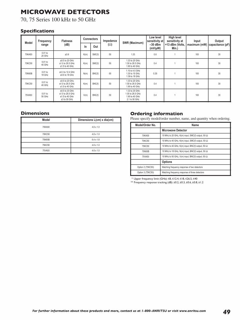
MICROWAVE DETECTORS70, 75 Series 100 kHz to 50 GHz
Dimensions Ordering informationPlease specify model/order number, name, and quantity when ordering.
* Upper frequency limit (GHz): ≤8, ≤12.4, ≤18, ≤26.5, ≤40** Frequency response tracking (dB): ±0.2, ±0.3, ±0.6, ±0.8, ±1.2
Specifications
Model Frequencyrange
Flatness(dB)
ConnectorsImpedance
(Ω) SWR (Maximum)
Low levelsensitivity at
–30 dBm(mV/µW)
High levelsensitivity at
+13 dBm (Volts,Min.)
Input maximum (mW)
Outputcapacitance (pF)
In Out
70KA500.01 to 20 GHz
±0.6 K(m) SMC(f) 50 1.33 0.6 1 100 30
70KC500.01 to 40 GHz
±0.5 to 20 GHz±1.0 to 26.5 GHz±1.5 to 40 GHz
K(m) SMC(f) 501.33 to 20 GHz
1.50 to 26.5 GHz1.90 to 40 GHz
0.4 1 100 30
75N50B0.01 to 18 GHz
±0.3 to 12.4 GHz±0.6 to 18 GHz
N(m) BNC(f) 501.15 to 4.5 GHz1.30 to 15 GHz1.39 to 18 GHz
0.35 1 100 30
75KC500.01 to 40 GHz
±0.5 to 20 GHz±1.0 to 26.5 GHz±1.5 to 40 GHz
K(m) BNC(f) 501.33 to 20 GHz
1.50 to 26.5 GHz1.90 to 40 GHz
0.4 1 100 30
75VA500.01 to 50 GHz
±0.5 to 20 GHz±1.0 to 26.5 GHz±1.5 to 40 GHz±3 to 50 GHz
V(m) BNC(f) 50
1.33 to 20 GHz1.50 to 26.5 GHz1.90 to 40 GHz2.1 to 50 GHz
0.4 1 100 30
Model Dimensions L(cm) x dia(cm)
70KA50 4.6 x 1.0
70KC50 4.6 x 1.0
75N50B 6.4 x 1.8
75KC50 4.6 x 1.0
75VA50 4.6 x 1.0
Model/Order No. Name
Microwave Detector
70KA50 10 MHz to 20 GHz, K(m) input, SMC(f) output, 50 Ω
70KC50 10 MHz to 40 GHz, K(m) input, SMC(f) output, 50 Ω
75KC50 10 MHz to 40 GHz, K(m) input, BNC(f) output, 50 Ω
75N50B 10 MHz to 18 GHz, N(m) input, BNC(f) output, 50 Ω
75VA50 10 MHz to 50 GHz, V(m) input, BNC(f) output, 50 Ω
Options
Option 2 (75KC50) Matching frequency response of two detectors
Option 3 (75KC50) Matching frequency response of three detectors
For further information about these products and more, contact us at 1-800-ANRITSU or visit www.anritsu.com 49

For further information about these products and more, contact us at 1-800-ANRITSU or visit www.anritsu.com50
MICROWAVE DETECTORS5400-71, 560-7 Series 1 MHz to 50 GHz
The Anritsu 560-7 and 5400-71 Series RF Detectors are usedwith the Model 56100A Scalar Network Analyzer and withSeries 54100A Scalar Measurement System for making coaxialtransmission loss or gain and power measurements. They are alsoused with the Site Master® and Cable Mate® Series PersonalSWR/RL and Fault Location Testers for makingpower measurements.
Features• Zero-biased Schottky diodes• –55 dBm to +16 dBm range
Specifications*
* The maximum input power is + 20 dBm for all microwave detectors with the exception of 5400-71N75L.
Ordering informationPlease specify model/order number, name, and quantity when ordering.
5400-71N50
Temperature range: 0°C to +70°C
Model/Order No. Name
Microwave Detector
5400-71N50 1 to 3000 MHz, N(m), 50 Ω
5400-71N75 1 MHz to 3 GHz, N(m), 75 Ω
5400-71N75L 0.005 to 1.2 GHz, N(m), 75 Ω
560-7K50 10 MHz to 40 GHz, K(m), 50 Ω
560-7N50B 10 MHz to 20 GHz, N(m), 50 Ω
560-7S50B 10 MHz to 20 GHz, WSMA(m), 50 Ω
560-7VA50 10 MHz to 50 GHz, V(m), 50 Ω
Model Frequency range Impedance Return loss Input connector Frequency response
5400-71N50 0.001 to 3 GHz 50 Ω 26 dB N(m)±0.2 dB, <1 GHz±0.3 dB, <3 GHz
5400-71N75 0.001 to 3 GHz 75 Ω 26 dB, <2 GHz20 dB, <3 GHz
N(m)±0.2 dB, <1 GHz±0.5 dB, <3 GHz
560-7N50B 0.01 to 20 GHz 50 Ω
15 dB, <0.04 GHz22 dB, <8 GHz
17 dB, <18 GHz14 dB, <20 GHz
N(m)±0.5 dB, <18 GHz
±1.25 dB, <20 GHz
560-7S50B 0.01 to 20 GHz 50 Ω
15 dB, <0.04 GHz22 dB, <8 GHz
17 dB, <18 GHz14 dB, <20 GHz
WSMA(m)±0.5 dB, <18 GHz
±1.25 dB, <20 GHz
560-7K50 0.01 to 40 GHz 50 Ω
12 dB, <0.04 GHz22 dB, <8 GHz
17 dB, <18 GHz15 dB, <26.5 GHz14 dB, <32 GHz13 dB, <40 GHz
K(m)
±0.5 dB, <18 GHz±1.25 dB, <26.5 GHz
±2.2 dB, <32 GHz±2.5 dB, <40 GHz
560-7VA50 0.01 to 50 GHz 50 Ω
12 dB, <0.04 GHz19 dB, <20 GHz15 dB, <40 GHz10 dB, <50 GHz
V(m)±0.8 dB, <20 GHz±2.5 dB, <40 GHz±3.0 dB, <50 GHz

For further information about these products and more, contact us at 1-800-ANRITSU or visit www.anritsu.com 51
POWER DIVIDERS11 Series DC to 3000 MHz
These RF power dividers are symmetrical, three-resistor tee designsthat can be used in applications where signals from DC to 3000 MHzmust be accurately divided. They are available in 50 ½ and provideexcellent amplitude and phase tracking.
Features• DC to 3000 MHz frequency range• Excellent amplitude and phase tracking• 50 Ω characteristic impedance
Specifications
Frequency (GHz)0 3
0
2
4
6
8
10
12
0
10
20
30
40
50
60
TypicalR
eturnLoss
(dB)
Typ
ical
Inse
rtio
nLo
ss(d
B)
Return lossInsertion loss
11N50B Insertion loss (typical) /return loss (typical)
31.75(MAX)
31.75 (MAX)
40.64 (MAX)
17.78(TYP.)
Dimensions in millimeters
11N50B outline
Ordering informationPlease specify model/order number, name, and quantity when ordering.
Maximum Input Power: 1 WattTemperature range: 0°C to +70°C
ModelFrequency
range(MHz)
SWRInsertion
loss(dB, max.)
Impedance(Ω)
Connectors
Input Output
11N50B DC to 3000 <1.25 7 50 N(f) N(f)
Model/Order No. Name
11N50B Power Divider, 1 MHz to 3 GHz, 50 Ω

For further information about these products and more, contact us at 1-800-ANRITSU or visit www.anritsu.com
POWER DIVIDERSK240, V240 Series DC to 65 GHz
Frequency (GHz)0 67
0
2
4
6
8
10
12
0
5
10
15
20
25
30
TypicalR
eturnLoss
(dB)
Typ
ical
Inse
rtio
nLo
ss(d
B)
Return loss
Insertion loss
Insertion loss (typical) /return loss (typical) for V240C
7.4 mm
7.4 mm
1
23
14.7 mm
10.2 mm
14.7 mm
10.2 mm
Ø 2.6 mm 2X
2-56 UNC-2B, 2X
9.1 mm
4.6 mm
6.6 mm TYP.
7.4 mm
K CONNECTOR FEMALE 1/4 - 36 UNS - 2A, 3X
K24
0CP
OW
ER
DIV
IDE
R
DC
-40
GH
z
Dimensions in Millimeters
K240B, K240C outline
4.6 mm
9.1 mm
2-56 UNC-2B, 2X
Ø 2.6 mm 2X
11.4 mm6.1 mm
10.2 mm14.7 mm
10.2 mm
14.7 mm
DC
-65
GH
z
32
1
7.4 mm
7.4 mmV CONNECTOR FEMALE THREAD M7.0 X .75-6G,2X
V24
0CP
OW
ER
DIV
IDE
R
Dimensions in Millimeters
V240C outline
Ordering informationPlease specify model/order number, name, and quantity when ordering.
These microwave power dividers are symmetrical, three-resistor teedesigns that can be used in applications where signals from DC to65 GHz must be accurately divided or combined. K Connector® iscompatible with 3.5 mm and SMA; V Connector® is compatiblewith 2.4 mm. All models have exceptional amplitude and phasetracking characteristics.
Features• DC to 65 GHz frequency range• K Connector® compatibility with SMA/3.5 mm• V Connector® compatibility with 2.4 mm• Excellent amplitude and phase tracking
Specifications
V240C
Maximum Input Power: 1WTemperature range: 0°C to +70°CWeight: 43g
Model/Order No. Name
K240B Precision Power Divider, DC to 26.5 GHz
K240C Precision Power Divider, DC to 40 GHz
V240C Precision Power Divider, DC to 65 GHz
Model Frequency range (GHz)
Impedance (Ω) Connectors
K240B DC to 26.5 50 K(f)
K240C DC to 40 50 K(f)
V240C DC to 65 50 V(f)
Frequencyrange (GHz)
Tracking of outputs Insertion loss(dB max.) SWR
Amplitude Phase
DC to 6 ±0.3 dB ±2° 7 1.22
6 to 18 ±0.3 dB ±3° 7.5 1.44
18 to 26.5 ±0.6 dB ±4° 8 1.58
26.5 to 40 ±0.6 dB ±6° 8.5 1.79
40 to 65 ±1.8 dB ±18° 10 3.11
52

For further information about these products and more, contact us at 1-800-ANRITSU or visit www.anritsu.com 53
POWER SPLITTERSK241, V241 Series, DC to 65 GHz
K241C
V241C
OUTPUT
OUTPUT
INP
UT
6.1 (TYP)
2.28
2.28
14.7
14.8 (MAX)
10.16
10.16
11.5
(TYP)
K Female Connector 1/4 - 36 UNS - 2A, 2X
K Male Connector 1/2 - 36 UNS - 2B
2.64 2X
2-56 UNC-2B, 2X
4.57
9.2
Dimensions in millimeters
K241B, K241C outline
4.6 mm
9.1 mm
2-56 UNC-2B, 2X
Ø 2.6 mm 2X
11.4 mm6.1 mm
10.2 mm14.7 mm
10.2 mm
14.7 mm
DC
-65G
Hz
PO
WE
RD
IVID
ER
V24
1CO
UT
OU
T
IN
7.4 mm
7.4 mm
V CONNECTOR MALE THREAD M7.0 X .75-6H
V CONNECTOR FEMALE THREAD M7.0 X .75-6G,2X
Dimensions in Millimeters
V241C outline
These microwave power splitters are symmetrical, two-resistordesigns that can be used in applications where signals from DC to65 GHz must be accurately divided for ratio measurements. Theyprovide excellent flatness and effective output SWR. K Connectors®
are compatible with 3.5 mm and SMA; V Connectors® arecompatible with 2.4 mm.
Features• DC to 65 GHz frequency range• K Connector® compatibility with SMA/3.5 mm• V Connector® compatibility with 2.4 mm• Excellent flatness and effective output SWR
Specifications
Ordering informationPlease specify model/order number, name, and quantity when ordering.
Maximum Input Power: 1WTemperature range: 0°C to +70°CWeight: 43g
Model/Order No. Name
K241B Precision Power Splitter, DC to 26.5 GHz
K241C Precision Power Splitter, DC to 40 GHz
V241C Precision Power Splitter, DC to 65 GHz
Model Frequencyrange (GHz)
Impedance(Ω)
Connectors
Input Output
K241B DC to 26.5 50 K(m) K(f)
K241C DC to 40 50 K(m) K(f)
V241C DC to 65 50 V(m) V(f)
ModelFrequency
range(GHz)
Flatness(dB)
InputSWR
EffectiveoutputSWR
Insertionloss(dB)
K241B DC to 26.5 2.0 1.45 1.45 7.5
K241CDC to 26.5 2.0 1.45 1.45 7.5
26.5 to 40 2.0 1.93 1.70 8.5
V241C
DC to 18 2.0 2.11 2.00 8.5
18 to 40 2.0 2.33 2.30 9.5
40 to 65 2.0 2.62 2.60 10.5
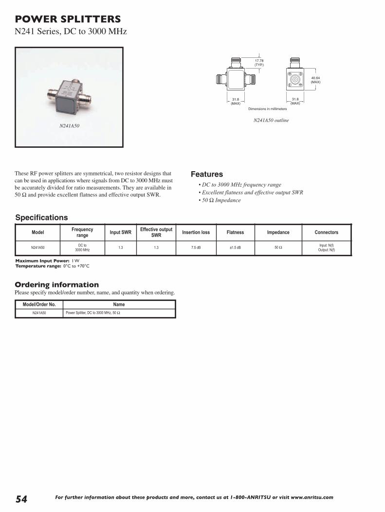
For further information about these products and more, contact us at 1-800-ANRITSU or visit www.anritsu.com
POWER SPLITTERSN241 Series, DC to 3000 MHz
These RF power splitters are symmetrical, two resistor designs thatcan be used in applications where signals from DC to 3000 MHz mustbe accurately divided for ratio measurements. They are available in50 Ω and provide excellent flatness and effective output SWR.
31.8 (MAX)
31.8 (MAX)
40.64(MAX)
17.78(TYP.)
Dimensions in millimeters
Ordering informationPlease specify model/order number, name, and quantity when ordering.
N241A50 outlineN241A50
Maximum Input Power: 1 WTemperature range: 0°C to +70°C
Model/Order No. Name
N241A50 Power Splitter, DC to 3000 MHz, 50 Ω
Model Frequency range Input SWR Effective output
SWR Insertion loss Flatness Impedance Connectors
N241A50DC to
3000 MHz1.3 1.3 7.5 dB ±1.5 dB 50 Ω Input: N(f)
Output: N(f)
Specifications
Features• DC to 3000 MHz frequency range• Excellent flatness and effective output SWR• 50 Ω Impedance
54

For further information about these products and more, contact us at 1-800-ANRITSU or visit www.anritsu.com 55
SPDT SWITCHDC to 65 GHz
45.5
33.90
40.6
17.8
8.88
28.702.54
BIAS
2 X 4-40UNC-2B
Dimensions in millimeters
SC4734, SC6135 outline
Coaxial 65 GHz microwave SPDT switchShort voltage pulse driven.
Features• Switching Speed: 20 msec max• Operating Voltage: 20 to 30V• Duty Cycle: 20 msec min
Ordering informationPlease specify model/order number, name, and quantity when ordering.
Temperature range: 0°C to +70°C*Call 1-800-ANRITSU for detailed information
Specifications*
Model Frequencyrange
Connectors Insertionloss (dB)
Returnloss (dB)
Isolation(dB)in out
SC4734 DC to 60 GHz V(f) V(f), V(f)1.5 ≤40 GHz3.0 >40 GHz
10 ≤40 GHz6 >40 GHz
29 ≤40 GHz26 >40 GHz
SC6135 DC to 65 GHz V(f) V(f), V(f)1.5 ≤40 GHz3.0 >40 GHz
10 ≤40 GHz6 >40 GHz
29 ≤40 GHz26 >40 GHz
Model/Order No. Name
SC4734 SPDT Switch, DC to 60 GHz
SC6135 SPDT Switch, DC to 65 GHz

56 For further information about these products and more, contact us at 1-800-ANRITSU or visit www.anritsu.com
BIAS TEEK250 100 MHz to 40 GHz, V250 100 MHz to 60 GHz
These bias tees are designed for applications where both DC and RFsignals must be applied to a device under test. They are particularlysuited for active device measurements. DC voltages of up to30 volts at 0.5 amps may be applied to test devices with negligibleeffect on RF performance. Low RF throughline loss (<1 dB) andlow return loss ensure negligible effect on measurements up to60 GHz. An RF input DC block isolates the input port from theapplied bias voltage.
Features• Broadband, 0.1 to 60 GHz coverage• Low SWR, low insertion loss• K Connector® and V Connector® availability
Specifications
DIMENSIONS IN MILLIMETERS
6.35 NOM
Ø 2.69 THRU
12.7 NOM
6.35 NOM
12.7 NOM 2.54 NOM
7.87 NOM
29.2 NOM
6.35 NOM
OUT
BIAS TEE K250 DCIN
RF IN
SMC MALE CONNECTOR
K FEMALE.25-36 UNS-2A
K MALE.25-36 UNS-2B
Outline (K and V models)
DC IN
RF OUTRFIN
Schematic diagram (K and V models)
Ordering informationPlease specify model/order number, name, and quantity when ordering.
Specifications
K250
➀ Usable between 0.04 and 0.1 GHz with degraded performance.Temperature range: 0°C to +70°C
Model/Order No. Name
K250 Precision Bias Tee, 100 MHz to 40 GHz
V250 Precision Bias Tee, 100 MHz to 60 GHz
Temperature 0 to 60°C
Mounting position Any
Weight 57g
Model Frequencyrange
Insertionloss Return loss RF power DC voltage DC current DC port isolation RF connectors DC connectors
K250 0.1 to 40 GHz➀ 1.2 dB typ.15 dB min. to 20 GHz10 dB min. to 40 GHz
1W max. 30V max. 0.5A20 dB at 0.1 GHz
40 dB above 0.5 GHzInput: K(m)Output: K(f)
SMC(m)
V250 0.1 to 60 GHz➀ 2.2 dB typ.13 dB min. to 20 GHz9 dB min. to 40 GHz8 dB min. to 60 GHz
1W max. 30V max. 0.5A20 dB at 0.1 GHz
40 dB above 0.5 GHzInput: V(m)Output: V(f)
SMC(m)

For further information about these products and more, contact us at 1-800-ANRITSU or visit www.anritsu.com 57
ULTRA-WIDEBAND BIAS TEESK251 50 kHz to 40 GHz, V251 100 kHz to 65 GHz
These ultra-wide bandwidth bias tees have been optimized foroptical communications and other high-speed pulse, data ormicrowave applications. Designed to simultaneously apply bothDC and RF drive signals to a device via a single input port, thesebias tees feature fast rise times, excellent low frequency response,minimum insertion loss and flat group delay. PrecisionK Connector® and V Connector® interfaces assure excellentimpedance match across the wide bandwidths available. A one yearwarranty is provided. Adapters are available to convert betweenK and V Connectors - See page 21 of this catalog for details.
Features• Ideal for Optical Communications Applications• Low Insertion Loss• Risetime: <5 ps typical (V251), <7 ps typical (K251)
Specifications
Specifications apply over the full DC Bias current range and over the temperature range of 0°C to +70°C.
4.45
1/4-36 UNS-2B
1/4-36 UNS-2A
2.03
2.03TYP
TYP
7.72
2X Ø.104 THRU
15.44
39.5
31.8 (MAX)
8.89
4.45
7.1
11.8
K251 BIAS TEE
RF IN
OUT
DCIN
S/N XXXXXX
33.4
SMC MALE CONNECTOR
K MALE CONNECTOR
MOUNTING HOLE
K FEMALE CONNECTOR
Dimensions in millimeters
33.7
4.45
M7.0 X .75-6H
M7.0 X .75-6G
2.03
2.03TYP
TYP
7.72
2X Ø.104 THRU
15.44
39.531.75
8.89
4.45
7.11
11.0
V251 BIAS TEE
RF IN
OUT
DCIN
S/N XXXXXX
SMC MALE CONNECTOR
V MALE CONNECTOR
MOUNTING HOLE
V FEMALE CONNECTOR
Dimensions in millimeters
K251 outline
V251 outline
K251
V251
ModelFrequency
range3dB BW
Insertion loss Return loss Rise time Group delay Max DC current
Max DC voltage
MaxRF power Connectors
K25150 kHz to40 GHz
<2 dB typical See Plot < 7 ps typical110 ± 2 ps
typical100 mA 16VDC 1 W
RF In: K(m)RF Out: K(f)
Bias: SMC(m)
V251100 kHz to
65 GHz< 2.5 dB typical See Plot < 5 ps typical
113 ± 2 ps typical
100 mA 16VDC 1 WRF In: V(m)RF Out: V(f)
Bias: SMC(m)

ULTRA-WIDEBAND BIAS TEESK251 50 kHz to 40 GHz, V251 100 kHz to 65 GHz
Ordering informationPlease specify model/order number, name, and quantity when ordering.
Typical Low Frequency Insertion Loss measured on V251 over the range of 1 kHz to 1 MHz.
Insertion Loss and Return Loss measured on V251 over the range of 40 MHz to 65 GHz.
Typical Uncorrected Pulse Response for V251. Absolute risetime for the BiasTee is derived from this measured data by applying the RSS method to
compensate for the risetime of the input pulse.
T meas. = uncorrected risetimeTBT = absolute Bias Tee risetimeTPG = risetime of input pulse
TBT2 + TPG2 = T meas.
Typical Low Frequency Insertion Loss and Return Loss measured on K251 over the range of 1kHz to 1 MHz.
Typical Frequency Insertion Loss and Return Loss measured on K251 over the range of 40 MHz to 40 GHz.
Model/Order No. Name
K251 Precision Bias Tee, 50 kHz to 40 GHz
V251 Precision Bias Tee, 100 kHz to 65 GHz
For further information about these products and more, contact us at 1-800-ANRITSU or visit www.anritsu.com58

For further information about these products and more, contact us at 1-800-ANRITSU or visit www.anritsu.com 59
KELVIN CONNECTION BIAS TEEK252, V252 DC to 65 GHz
K252
Ordering informationPlease specify model/order number, name, and quantity when ordering.
ModelFrequency
Range 3dB BW
Insertion Loss Return Loss Max DC Current
Max DC Voltage Max RF Power Connectors Inductance
K252 100 MHz to 40 GHz <2.5 dB typical 11 dB 500 mA 50 VDC 1 W
RF In: K(m)RF Out: K(f)
Bias: SMC(m)Sense: SMC(m)
Bias: 14 µHSense: 8 µH
V252 100 MHz to 65 GHz <3.7 dB typical10 dB to 60 GHz8 dB to 65 GHz
500 mA 50 VDC 1 W
RF In: V(m)RF Out: V(f)
Bias: SMC(m)Sense: SMC(m)
Bias: 14 µHSense: 8 µH
Model/Order No. Name
K252 Kelvin Bias Tee, 0.1 to 40 GHz
V252 Kelvin Bias Tee, 0.1 to 65 GHz
Kelvin Connection Bias Tee is designed for applications where bothDC and RF signals are applied to the Device under Test (DUT) andprecision DC measurements are required. A high resistance of theDC Coil results in a voltage drop that leads to a DC Biasing voltageerror in the measurements. A Kelvin connection bias tee is used toeliminate DC Biasing errors as the sense coil allows accuratemeasurement of the DC Voltage applied across the DUT. Both 40GHz and 65 GHz models are available with precision K connectors®and V Connectors® respectively. A male connector for the RF inputand a female connector for the output is the standard interface forK252 and V252 Bias Tees. A SMC connector is standard for DCBias and Sense connections. Other connector types with differentconnector configurations can be ordered through factory.
Features• Broadband 0.1 to 65 GHz frequency coverage• 50 V and 500 mA Current capability• Low Insertion and SWR performance

60 For further information about these products and more, contact us at 1-800-ANRITSU or visit www.anritsu.com
ULTRA-WIDEBAND BIAS TEESV255 50 kHz to 65 GHz
S/N 110020V255 BIAS TEE
RF OUT
RF IN
DCIN
7.1
21.3
39.6
2.0
2.8
2.8
6.5
52.8
61.7
6.5 7.0
14.0
10.7
V-MALE CONNECTORM7.0 X 75-6H
V-FEMALE CONNECTORM7.0 X 75-6G
2X MOUNTING HOLE∅ 2.5[.10] THRU
SMC MALE CONNECTOR
Dimensions in millimeters
V255 outline
V255
The V255 Gen II Ultra Wideband Bias Tee is designed to meet thehigh electrical performance requirement of passive components inoptical communication networks. Given a broader bandwidth of50 kHz to 65 GHz, with low insertion losses and very good returnloss, makes it ideal to use in 40 Gbps systems to bias opticalmodulators and broad band data drivers. It's fast rise time and flatgroup delay performance allows extremely accurate measurementswithin a laboratory environment. The V255 Bias Tee comes with astandard V Connector® that assures excellent impedance matchacross the available wide bandwidth. The DC signal can beapplied or extracted from the bias tee through an SMC connectorat the third port. As with our other bias tees, the V255 also has aone-year warranty.
Specifications
Features• Ideal for Optical Communication applications.• Very low Insertion Loss• Rise Time 3 ps typical • High Current Capacity• High Isolation between Input Port and DC Port
Model Frequency range Insertion loss Return loss Rise time Group delay Max DC current
Max DC voltage
Min.Isolation
Operatingtemperature
V25550 kHz to 65 GHz
(30 kHz to 65 GHz typical)1.2 dB to 65 GHz
typical<–15 dB to 65 GHz
typical 3 ps typical 125 ± 2 ps typical 400 mA 16 VDC –50 dBm 0˚C to 80˚C

ULTRA-WIDEBAND BIAS TEESV255 50 kHz to 65 GHz
Typical Group Delay Performance measured on V255 using Anritsu 37397C VNA
Typical High Frequency Insertion Loss and Return Loss measured on V255over the range of 40 MHz to 65 GHz using Anritsu 37397C VNA
Typical Isolation between Data I/P and DC Port using Anritsu 37397C VNA
Typical Low Frequency Insertion Loss and Return Loss measured on V255 Bias Tee over the range of 10 kHz to 300 kHz
Ordering informationPlease specify model/order number, name, and quantity when ordering.
Model/Order No. Name
V255 Gen II Wideband Bias Tee, 50 kHz to 65 GHz
Input Test Signal to V255 2.0 V NRZ Input Signal using Anritsu 43G ME7750A BERT
V255 Output Response to 2.0V NRZ Input Signal using Anritsu 43G ME7750A BERT
For further information about these products and more, contact us at 1-800-ANRITSU or visit www.anritsu.com 61

For further information about these products and more, contact us at 1-800-ANRITSU or visit www.anritsu.com62
PRECISION DC BLOCKSK261, 10 kHz to 40 GHz, V261 50 kHz to 65 GHz
3.96
15.44
9.534.78
7.92
K261
1/4-36 UNS-2B 1/4-36 UNS-2A
11.8
33.5
K MALE CONNECTOR K FEMALE CONNECTOR
Dimensions in millimeters
3.96
34.0
15.4411.5
9.534.78
7.92
V261
M7.0 X .75-6H M7.0 X .75-6GV MALE CONNECTOR V FEMALE CONNECTOR
Dimensions in millimeters
K261 outline
V261 outline
These ultra-wide bandwidth DC Blocks have been optimizedfor optical communications and other high-speed pulse, data ormicrowave applications. Designed to apply AC drive signals to adevice while eliminating any DC components, these DC Blocksfeature wide bandwidth, excellent low frequency response,minimum insertion loss and flat group delay. PrecisionK Connector® and V Connector® interfaces assure excellentimpedance match across the wide bandwidths available. A oneyear warranty is provided.
Features• Ideal for Optical Communications and
high speed Pulse Applications• <1.0 dB Insertion Loss (K261)• Risetime: <5 ps (V261), <7 ps (K261)
Specifications
V261
K261
Specifications apply over the temperature range of 0°C to +70°C.
Model Frequency range 3 dB BW Insertion loss Return loss Rise time Group delay Max
DC voltageMax
RF power Connectors
K26110 kHz to40 GHz
<1.0 dB typical See Plot < 7 ps typical 110 ±1 ps typical 16VDC 1 WRF In: K(m)RF Out: K(f)
V26150 kHz to65 GHz
< 2.0 dB typical See Plot < 5 ps typical 113 ±1 ps typical 16VDC 1 WRF In: V(m)RF Out: V(f)

PRECISION DC BLOCKSK261, 10 kHz to 40 GHz, V261 50 kHz to 65 GHz
Typical Low Frequency Insertion Loss measured on V261 over the range of 1 kHz to 1 MHz.
Insertion Loss and Return Loss measured on V261 over the range of 40 MHz to 65 GHz.
Typical Uncorrected Pulse Response for V261. Absolute risetime for the DCBlocks is derived from this measured data by applying the RSS method to
compensate for the risetime of the input pulse.
T meas. = uncorrected risetimeTBT = absolute Bias Tee risetimeTPG = risetime of input pulse
TBT2 + TPG2 = T meas.
Ordering informationPlease specify model/order number, name, and quantity when ordering.
Typical Low Frequency Insertion Loss measured on K261 over the range of 1 kHz to 1 MHz. Insertion Loss and Return Loss measured on K261 over the range
of 40 MHz to 40 GHz.
Model/Order No. Name
K261 Precision DC Block, 50 kHz to 40 GHz
V261 Precision DC Block, 100 kHz to 65 GHz
For further information about these products and more, contact us at 1-800-ANRITSU or visit www.anritsu.com 63

64 For further information about these products and more, contact us at 1-800-ANRITSU or visit www.anritsu.com
DC BLOCKSV265, 50 kHz to 65 GHz
V265 outline
The V265 DC Block has been designed and optimized for opticalcommunications and other high speed pulse, data or microwaveapplications. Based on the coaxial resilient connection – which isthe same as on our V255 Gen II Bias Tee – it provides excellent lowfrequency response with very low losses and flat group delay overthe temperature of operation. Designed to apply AC drive signals toa device while eliminating any DC voltage or current components,the V265 DC Block can be used in isolating DC leakage betweentwo electrical components. The DC block comes with a standardV Connector® and assures excellent impedance match across thewide bandwidth available. A one-year warranty is provided.
Specifications
Features• Ideal for Optical Communication applications.• Low Insertion Loss• Rise Time 3 ps typical
V265
Model Frequencyrange Insertion loss Return loss Rise time Group delay Max
DC voltageMax
RF power Connectors Operatingtemperature
V26550 kHz to 65 GHz30 kHz to 65 GHz
typical
<0.7 dB to 65 GHztypical
–15 dB to 65 GHztypical
3 ps typical 84 ±2 ps typical 16 VDC 1 WRF In: V(f)
RF Out: V(m)0˚C to 80˚C
V265
11.5 8.6
27.8
V MALE CONNECTORM7.0 X .75-6H
V FEMALE CONNECTORM7.0 X .75-6G
7.1ACROSS FLATS
7.9
7.9
Dimensions in millimeters

PRECISION DC BLOCKSV265, 50 kHz to 65 GHz
Typical Low Frequency Insertion Loss and Return Loss measured on V265 BiasTee over the range of 10 kHz to 300 kHz using
Anritsu MS4630B Network Analyzer
Ordering informationPlease specify model/order number, name, and quantity when ordering.
Typical High Frequency Insertion Loss and Return Loss measured on V265over the range of 40 MHz to 65GHz using Anritsu 37397C VNA
Typical Group Delay Performance measured on V265 using Anritsu 37397C VNA
Input Test Signal to V265 2.0 V NRZ Input Signal using Anritsu 43G ME7750A BERT
V265 Output Response to 2.0V NRZ Input Signal using Anritsu 43G ME7750A BERT
Model/Order No. Name
V265 DC Block, 50 kHz to 65 GHz
For further information about these products and more, contact us at 1-800-ANRITSU or visit www.anritsu.com 65

For further information about these products and more, contact us at 1-800-ANRITSU or visit www.anritsu.com66
UNIVERSAL TEST FIXTURES3680 Series DC to 60 GHz
The 3680 series provide an accurate, repeatable solution formeasuring microstrip and Coplanar substrate devices. Input andoutput connections are made to the substrate device by two spring-loaded jaws that include coax-to-microstrip/Coplanar launchers.The jaws accommodate substrates from 0.13 to 1.9 mm in thickness.No center section is required. One jaw is movable in two dimensionsto accommodate substrates up to 50 mm long (100 mm for 3680-20)and substrates with line offsets of up to 12.7 mm (25 mm for 3680-20). The 3680 series includes three models: the 3680-20covers DC to 20 GHz with APC-3.5™ connectors, the 3680K coversDC to 40 GHz with Anritsu's K Connector®, and the 3680Vcovers DC to 60 GHz with Anritsu's V Connector®.
Features• DC to 60 GHz coverage• Microstrip and coplanar measurement capability• Accommodates offset and right-angle test devices• Calibration/verification kits (optional)• Substrate measurement capability
Substrate Measurement CapabilityProviding substrate measurement capability for your microstrip orcoplanar waveguide designs, the 3680 Series Universal Test Fixturesallow accurate, repeatable transitions from coax to microstrip orcoax to coplanar waveguide (CPW). Complete substratemeasurement systems comprised of a Universal Test Fixture, avector or scalar network analyzer, and a "substrate" Calibration Kitcan fulfill your microstrip or CPW test needs. Anritsu provides thecomplete measurement solution, the test fixtures, the calibration kits,and the test equipment for measurements on substrate devices. Ourtotal system responsibility ensures compatible system components,designed to work together properly. Guaranteed system specsprovide assurance that your test results are accurate and verifiable.
Universal Test FixturesThe most critical part of any substrate measurement system is thelaunching fixture. It must be simple yet flexible, easy to use, andmost of all provide accurate, repeatable measurements. OurUniversal Test Fixtures are designed to meet these requirements.Three versions of the Universal Test Fixture are available: the 3680-20, DC to 20 GHz; the 3680K, DC to 40 GHz; and the 3680V, DCto 60 GHz. The fixture consists of a fixed connector and a movableconnector that can be positioned for substrates up to 2 inches long.No center section is required. The substrate is held in place betweenspringloaded jaws. This allows the fixture to accommodate differentdevices without requiring a custom center section for each differentlength. The unique jaw action ensures solid, repeatable electricalcontact. The jaw tension is defined by the force of a spring,independent of human judgment errors. This means the tension willalways be the same, providing more repeatable measurements.Dielectric rods behind the jaws accurately position the substrateaway from thelaunch to reducefringing capacitanceand contribute to thefixture’s excellentrepeatability. With aUniversal TestFixture you can besure yourmeasurements areboth accurate andrepeatable.
Microstrip or Coplanar WaveguideMeasurementsThe unique design ofthe 3680 providesmeasurementcapability for eithermicrostrip orcoplanar waveguide(CPW) designs. Allthat is required is asimple jaw change.The 3680 does thejob of two fixtures,saving you time andmoney. A substratemeasurement systemwith the 37xxx seriesVNA is the only measurement system capable of directly providingmicrostrip dispersion compensation. Microstrip is a dispersivemedia - phase shift is not linear with respect to frequency. OurVector Network Analyzer’s ability to compensate for this dispersioncan dramatically improve vector measurement accuracy and provideyou with the most accurate vector measurements possible.

UNIVERSAL TEST FIXTURES3680 Series DC to 60 GHz
Offset MeasurementsWith a 3680-basedsubstrate measurementsystem, there is no needto force your designsinto a straight line orleave your designsuntested. The 3680 hasthe ability to offset linesby as much as ±_ inch.Many designs, such asfilters, require paralleltraces that are offset. Inthe past, designers were forced to add extra line lengths, create one-of-a-kind custom fixtures, or worse, not test offset designs. With theflexibility of the 3680, you can test offset or in-line designs with onesetup. Formerly-untestable designs can now be tested with ease.
Right-Angle MeasurementsTesting designs with right-angle connections is made easy. Theoptional rightangle launcher adds a connection at 90° to the fixture.This lets you test devices with right-angle connections withprecision and repeatability corresponding to an in-linemeasurement. The fixture is designed to fit your device; you don’thave to design your device to fit the fixture. The right-anglelauncher also provides another benefit - the ability to test multiportdevices. With the addition of right-angle launchers, the 3680 canbecome a three port, or even four port launching fixture. A 37xxxseries VNA-based microstrip measurement system with optionaldual source control can interdependently control up to two sourcesand a receiver, for testing mixers or other frequency conversiondevices. Now a microstrip or CPW mixer, converter, or other devicecan be tested, with the same convenience as a packaged device.
60 GHz MeasurementsAnritsu was the first manufacturer to offer a coaxial VNA withcontinuous 0.04 GHz to 60 GHz measurement capability. With the3680 Series Universal Test Fixtures, that measurement capability isextended onto the substrate. An Anritsu VNA-based substratemeasurement system is capable of measurements from 0.04 GHz to60 GHz in one setup. And the optional 60 GHz time domaincapability provides time or distance measurements with unsurpassedresolution. Discontinuities as close as 1.2 mm on alumina can beresolved. You can measure devices whose performance couldpreviously only be theorized. The 3680V, has excellent return lossand insertion loss from DC to 60 GHz. In a substrate measurementsystem, that translates to improved accuracy and repeatability, formore accurate characterization of your microstrip or CPW designs.
Bias CapabilityFor active device measurements, the 3680 has bias capability eitherthrough the RF connection or through a bias probe. With optionalmultiple bias probes, you can inject bias into any point on yourdevice under test. The bias probe provides infinite placementresolution and eliminates the need for external bias hardware.Alternately, if your active device is biased through an RFconnection, bias teescan be used to combinebias and RF at anylaunch point. The3680’s flexible biasinjection eliminates theneed for multiplefixtures, saving youtime and money. Up tofour bias probes can beaccommodated.
MMIC MeasurementsWith the optional MMIC attachment, you can test MMIC’s and verysmall components as conveniently as other devices. A MMICattachment consists of a center carrier, with microstrip lines forlaunching, and cam-operated pressure rods. The MMIC componentis placed on the center carrier between microstrip lines. (Machinablecenter carrier blocks are available for your custom designs.) Contactwith the component is made with spring tabs, for reliability anddamage protection. The unique design of the MMIC attachmentassures solid, repeatable measurements on any small device. AnAnritsu substrate measurement system can fulfill all your substratemeasurement needs including, with a MMIC attachment, very smallsubstrates and MMICs.
Calibration/Verification KitsA full complement of calibration kits for microstrip or coplanarwaveguide are available. Standard Open Short Load (OSL) andLine Reflect Line (LRL) calibration components are included. Thesubstrates for these cal kits are carefully selected for properimpedance and consistency, to provide the most accuratemeasurements possible. Included with every cal kit is a Beattystandard (standard mismatch) and a 20 dB offset termination. Nowyou can verify, in the fixture, the quality of your calibrations. Thisverification, available only from Anritsu, ensures the validity ofyour device measurements.
For further information about these products and more, contact us at 1-800-ANRITSU or visit www.anritsu.com 67

For further information about these products and more, contact us at 1-800-ANRITSU or visit www.anritsu.com68
UNIVERSAL TEST FIXTURES3680 Series DC to 60 GHz
Electrical
Ordering informationPlease specify model/order number, name and quantity when ordering.
➀ 36805 series includes (4) substrate launchers for the 36802 MMIC attachment
Temperature range: –20° to 70°C
Model Universal Test Fixture
Right-AngleLauncher
MMICAttachment
3680-20 3680K 3680V 36801K 36801V 36802
Frequency range (GHz)
DC to 20 DC to 40 DC to 60 DC to 30 DC to 50 DC to 60
Return loss (dB)DC to 20 GHz20 to 40 GHz40 to 60 GHz
>17>17>14
>17>14>8
>16>12
>16>12>7
>12>8>6
Repeatability (dB)DC to 20 GHz20 to 40 GHz40 to 60 GHz
<±0.10<±0.10<±0.20
<±0.10<±0.20<±0.30
<±0.15<±0.25
<±0.15<±0.25<±0.40
<±0.20<±0.40<±0.60
Model/Order No. Name
Main frame
3680-20 Universal Test Fixture (20 GHz)
3680K Universal Test Fixture (40 GHz)
3680V Universal Test Fixture (60 GHz)
Accessories
36801K Right-Angle Launcher (30 GHz)
36801V Right-Angle Launcher (50 GHz)
36802 MMIC Attachment
36803 Bias Probe
36805-10M 10 mil launchers➀
36805-15M 15 mil launchers➀
36805-25M 25 mil launchers➀
Calibration/verification kits
36804B-10M 10 mil microstrip cal/verif. kit, DC to 50 GHz
36804B-15M 15 mil microstrip cal/verif. kit, DC to 30 GHz
36804B-25M 25 mil microstrip cal/verif. kit, DC to 15 GHz
36804-25C 25 mil coplanar waveguide cal/verif. kit, DC to 20 GHz
Specifications
3680
serie
sU
nive
rsal
Test
Fixt
ure
Substrate types supported Microstrip or coplanar waveguide
Overall size 10 x 12.7 x 6.4 cm
Substrate length0.5 cm min.5 cm max.[10 cm with 3680-20]
Maximum substrate width No limit
Substrate thickness0.012 cm min.0.19 cm max.
Maximum line offset±1.2 cm[±2.5 cm with 3680-20]
Input and output connectors3680-20: APC-3.5™ female3680K: K Connector® female3680V: V Connector® female
3680
2M
MIC
Atta
chm
ent Substrate thickness 0.0 cm, 0.038 cm, 0.064 cm
Minimum test substrate length 1.5 mm
Maximum test substrate length 1.17 cm with standard block
Maximum line offset ±1.2 cm
3680
1R
ight
Ang
leLa
unch
er Distance from in-line connector, axialMinimum: 1 cm Maximum: 4 cm
Distance from in-line connector, offsetMinimum: 0.0 cmMaximum: 2 cm

For further information about these products and more, contact us at 1-800-ANRITSU or visit www.anritsu.com 69
LIMITERS1 Series 1 MHz to 26.5 GHz
Broadband microwave limiter features• High power protection: Up to 5 Watts• Very fast turn-on time: 10 ns max.• Broad frequency range: 0.001 to 26.5 GHz• Low insertion loss: 2.7 dB to 20 GHz• Excellent return loss: 11 dB at 20 GHz• Single side limiting
1N50C
1K50B
Dimensions in millimeters
30 25
25
N Connector MaleN Connector Female
LIM
ITE
RS
MO
DE
L1N
75B
FR
EQ
UE
NC
YR
AN
GE
1MH
z-
3000
MH
z
MAXIMUM INPUTS
RF LIMITERS
N Connector Male N Connector Female
95
32.313
21 Dia. 15.7 Dia.
Dimensions in millimeters
MAXIMUM INPUTS
RF LIMITERS
17.413
40
17.4 Dia.
K Connector Male K Connector Female
Dimensions in millimeters
1N50C and 1N75C Limiters outline
1K50A and 1K50B Limiters outline
1N50B and 1N75B Limiters outline
Limiting Level: Limiter begins compressing at approximately +10 dBm. In compression, output level increases by 0.25 to 0.5 dB for each 1 dB increase at the input. Output powerat 5W input at 500 MHz is 21 dBm max.Dimensions: 1N50B and 1N75B 3.8 cm x 2.5 cm x 2.5 cmTemperature range: 0°C to +70°C
Ordering informationPlease specify model/order number, name and quantity when ordering.
Model/Order No. Name
Limiter
1N50B N(m) to N(f), 50 Ω, 1 MHz to 3 GHz
1N75B N(m) to N(f), 75 Ω, 1 MHz to 3 GHz
1N50C N(m) to N(f), 50 Ω, 10 MHz to 18 GHz
1N75C N(m) to N(f), 75 Ω, 10 MHz to 3 GHz
1K50A K(m) to K(f), 50 Ω, 10 MHz to 20 GHz
1K50B K(m) to K(f), 50 Ω, 10 MHz to 26.5 GHz
Model Frequency range
Max. input power
Min. return loss
(at 0 dBm input)
Max.insertion loss
(at 0 dBm input)
Max. turn-on time
Input connector
Output connector
Input/outputcoupling
1K50B 0.01 to 26.5 GHz 3 Watts 10 dB 3.9 dB 10 ns K(m) K(f) DC
1K50A 0.01 to 20 GHz 5 Watts14 dB, ≤12 GHz 11 dB, >12 GHz
2.7 dB 10 ns K(m) K(f) DC
1N50C 0.01 to 18 GHz 5 Watts14 dB, ≤12 GHz11 dB, >12 GHz
2.9 dB 10 ns N(m) N(f) DC
1N75C 0.01 to 3 GHz 5 Watts 15 dB 1.1 dB 10 ns 75 Ω N(m) 75 Ω N(f) DC
1N50B 0.001 to 3 GHz 1.5 Watts 19 dB 1.3 dB 10 ns N(m) N(f) AC
1N75B 0.001 to 3 GHz 1.5 Watts 19 dB 1.3 dB 10 ns 75 Ω N(m) 75 Ω N(f) AC
Specifications

70 For further information about these products and more, contact us at 1-800-ANRITSU or visit www.anritsu.com
MATCHING PADS12 Series DC to 3000 MHz
Specifications
RF matching pad and impedance adapter features
• DC to 3000 MHz frequency range• Matching pad matches 50 Ω to 75 Ω or 75 Ω to 50 Ω circuits
The 12N50-75B matching pad is a two-resistor design that matches50 Ω to 75 Ω or 75 Ω to 50 Ω circuits.
12N50-75B
Temperature range: 0°C to +70°CDimensions: 3.8 cm x 2.5 cm x 2.5 cm
Ordering informationPlease specify model/order number, name and quantity when ordering.
Model Frequencyrange (MHz) SWR Insertion loss
(dB) Connectors
12N50-75B DC to 3000 1.25 7.5 max.N(m) 50 Ω to
N(f) 75 Ω
Model/Order No. Name
12N50-75B Matching Pad, DC to 3000 MHz

For further information about these products and more, contact us at 1-800-ANRITSU or visit www.anritsu.com 71
VNA AND VNMS CALIBRATION KITS
3651A Option 1
The Anritsu Calibration Kits contain all the precision componentsand tools required to calibrate your VNA or VNMS for 12-termerror-corrected measurements in the connector style of your choice.Components are included for calibrating male and female test portsas required. The kits support calibration with opens, shorts, andbroadband loads. Option 1 adds sliding terminations and a pin depthgauge where required.
The following kits are for use with 37xxx LightningVNAs, MS464xA VectorStar, and MS20xxx VNA Master.
3650A SMA/3.5 mm Calibration Kit consisting of:• 34ASF50-2 Female Adapter (2)• 33SFSF50 Female-Female Adapter (2)*• 33SS50 Male-Male Adapter*• 28S50-2 Broadband Male Termination (2)• 28SF50-2 Broadband Female Termination (2)• 33SSF50 Male-Female Adapter (2)*• 24S50 Male Open• 24SF50 Female Open• 23S50 Male Short• 23SF50 Female Short• 34AS50-2 Male Adapter (2)• Connector Thumb Wheel (4)• 01-201 Torque Wrench• 01-210 Reference Flat• 01-222 Pin Depth Gauge• 01-223 Pin Depth Gauge • Calibration coefficients diskette• Calibration coefficients memory stick
Option 1Adds the following:
• 17SF50 Female Sliding Termination • 17S50 Male Sliding Termination
3651A GPC-7 Calibration Kit consisting of:• 28A50-2 Broadband Termination (2)• 24A50 Open• 23A50 Short• 01-200 Torque Wrench• 01-221 Collet Extractor Tool and 4 Collets• Calibration coefficients diskette• Calibration coefficients memory stick
Option 1Adds the following:
• 17A50 Sliding Termination • 01-210 Reference Flat• 01-220 Pin Depth Gauge
3652A K Connector® Calibration Kit consisting of:• 34AKF50 Female Adapter (2)• 33KFKF50B Female-Female Adapter (2)*• 33KK50B Male-Male Adapter*• 28K50A Broadband Male Termination (2)• 28KF50A Broadband Female termination (2)• 33KKF50B Male-Female Adapter (2)*• 24K50 Male Open• 24KF50 Female Open• 23K50 Male Short• 23KF50 Female Short• 34AK50 Male Adapter (2)• 01-201 Torque Wrench• 01-210 Reference Flat• 01-222 Pin Depth Gauge• 01-223 Pin Depth Gauge• Calibration coefficients diskette• Connector thumb wheel (4)• Calibration coefficients memory stick
Option 1Adds the following:• 17KF50 Female Sliding Termination • 17K50 Male Sliding Termination
3653A Type N Calibration Kit consisting of:• 23NF50 Female Short• 23N50 Male Short• 24NF50 Female Open• 24N50 Male Open• 28N50-2 Broadband Male Termination (2)• 28NF50-2 Broadband Female Termination (2)• 34AN50-2 Male Adapter (2)• 34ANF50-2 Female Adapter (2)• 01-213 Reference Gauge• 01-224 Pin Depth Gauge• Calibration coefficients diskette• Calibration coefficients memory stick
3654D

VNA AND VNMS CALIBRATION KITS
The following kits are recommended for use with37xxx Lightning and MS464xA VectorStar.
3654D V Connector® Calibration Kit consisting of:• 23V50C-5.1 Male Short 5.1mm • 23VF50C-5.1 Female Short 5.1mm• 24V50C Male Open • 24VF50C Female Open • 28V50D Male Broadband Termination (2)• 28VF50D Female Broadband Termination (2)• 33VV50C Male-Male Adapter*• 33VFVF50C Female-Female Adapter (2)*• 33VVF50C Male-Female Adapter (2)*• Calibration coefficients diskette• Connector thumb wheel (4) • 01-201 Torque Wrench• 01-210 Reference Flat• 01-322 Pin Depth Gauge • 01-323 Female Adapter for pin gauge • 01-204 Adapter Wrench • 01-312 Male Flush Short • 01-311 Female Flush Short• Calibration coefficients memory stick
Option 1Adds the following::
• 17VF50C Female Sliding Load• 17V50C Male Sliding Load
3655 Series Waveguide Calibration KitThe 3655 Series Calibration Kit contains all of the precisioncomponents and tools required to calibrate your VNA for 12-termerror-corrected measurements of test devices with the appropriatewaveguide designation. Components are included for calibratingboth module ports. The kit supports calibration with offset shortsand broadband loads. Option 1 adds a sliding termination.
Consisting of:• Short, Flush (2)• Offsets, 1/8 and 3/8 Wavelength• Terminations, Fixed (2)• Test Port Sections (2)
Option 1Adds the following:
• Sliding Termination
3656B W1 Calibration Kit consisting of:• 23W50-1 Male Offset Short (2.02 mm)• 23W50-2 Male Offset Short (2.65 mm)• 23W50-3 Male Offset Short (3.180 mm)• 24W50 Male Open (1.510 mm)• 28W50 Male Broadband Termination• 23WF50-1 Female Offset Short 1 (2.02 mm)• 23WF50-2 Female Offset Short 2 (2.65 mm)• 23WF50-3 Female Offset Short 3 (3.180 mm)• 28WF50 Female Broadband Termination• 24WF50 Female Open (1.930 mm)• 33WSC50 Fixed Male SC Connector• 33WFSC50 Fixed Female SC Connector• Interchangeable Sliders, SC Connectors• Locking Keys, SC Connectors• 01-402 Interchange Adapter Fixed Male• 33WWF50 Male-Female Adapter• 33WW50 Male-Male Adapter• 33WFWF50 Female-Female Adapter• 01-504 6 mm Torque Wrench• 01-505 6-7 mm End Wrench• 18WWF50-1B Stepped Impedance Thruline (Verification Device)• 18WWF50-1 50Ω Matched Thruline (Verification Device)• Calibration coefficients diskette• Calibration coefficients memory stick
The following kits are compatable with MS20xx VNAMaster. They are not recommended for use with the37xxx Lightning or MS464xA VectorStar.
3750R SMA/3.5 mm 9 GHz Calibration Kit consisting of:• 23LF50 Female Short• 23L50 Male Short• 24LF50 Female Open• 24L50 Male Open• 28L50R Male Termination (2)• 28LF50R Female Termination (2)• 01-204 Adapter wrench• Calibration coefficients diskette
3751R GPC-7 9 GHz Calibration Kit consisting of:• 23A50 Short• 24A50 Open• 28A50R Termination (2)• Calibration coefficients diskette
3753R Type N 9 GHz Calibration Kit consisting of:• 23NF50 Female Short• 24NF50 Female Open• 24N50 Male Open• 28NF50R Female Termination (2)• 28N50R Male Termination (2)• 23N50 Male Short• Calibration coefficients diskette
3753-75R 75 Ω Type N 3 GHz Calibration Kit consisting of:
• 23N75-3 Male Short• 23NF75-3 Female Short• 24N75-3 Male Open• 24NF75-3 Female Open• 28N75-3 Male Termination (2)• 28NF75-3 Female Termination (2)• 34NN75-3 Male-Male Adapter• 34NNF75-3 Male-Female Adapter• 34NFNF75-3 Female-Female Adapter• Calibration coefficients diskette
Ordering informationPlease specify model/order number, name and quantity when ordering.
* Phase Equal Adapters
Model/Order No. Name
Calibration kits3650A SMA/3.5 mm calibration kit
Option 1 Adds sliding terminations
3651A GPC-7 calibration kit
Option 1 Adds sliding terminations
3652A K Connector® calibration kit
Option 1 Adds sliding terminations
3653A Type N calibration kit
3654D V Connector® calibration kit
Option 1 Adds sliding terminations
3655E WR12 Waveguide calibration kit
Option 1 Adds sliding terminations
3655V WR15 Waveguide calibration kit
Option 1 Adds sliding terminations
3655W WR10 Waveguide calibration kit
Option 1 Adds sliding terminations
3656B W1 calibration kit
3750R SMA/3.5 mm 9 GHz calibration kit
3751R GPC-7 9 GHz calibration kit
3753R Type N 9 GHz calibration kit
3753-75R 75 Ω Type N 3 GHz calibration kit
For further information about these products and more, contact us at 1-800-ANRITSU or visit www.anritsu.com72

For further information about these products and more, contact us at 1-800-ANRITSU or visit www.anritsu.com 73
VNA AND VNMS VERIFICATION KITS
Ordering informationPlease specify model/order number, name and quantity when ordering.
3669B
Model/Order No. Name
Verification kits
3663 Type N verification kit
3666 SMA/3.5 mm verification kit
3667 GPC-7 verification kit
3668 K Connector® verification kit
3669B V Connector® verification kit
The Anritsu Verification Kits contain precision componentswith characteristics that are traceable to NIST. Used primarily by themetrology laboratory, these components provide the most dependablemeans of determining the system accuracy of your VNA. A diskcontaining factory measured test data for all components is suppliedfor comparison with customer-measured data.
The following kits are for use with 37XXX Lightning VNAs.
3663 Type N Verification Kit consisting of:• 42N-50, 50 dB Attenuator• 18N50-10, 10 cm Airline• 42N20, 20 dB Attenuator• 18N50-10B, 10 cm Stepped Impedance Airline (Beatty standard)• Verification kit disks
3666 SMA/3.5 mm Verification Kit consisting of:• 19S50-7, 7.5 cm Airline• 19S50-7B, 7.5 cm Stepped Impedance Airline (Beatty standard)• 42S-50, 50 dB Attenuator• 42S-20, 20 dB Attenuator• Verification kit disks
3667 GPC-7 Verification Kit consisting of: • 42A-50, 50 dB Attenuator• 18A50-10, 10 cm Airline• 42A-20, 20 dB Attenuator• 18A50-10B, 10 cm Stepped Impedance Airline (Beatty standard)• Verification kit disks
3668 K Connector® Verification Kit consisting of: • 19K50-7, 7.5 cm Airline• 42K-50, 50 dB Attenuator• 42K-20, 20 dB Attenuator• 19K50-7B, 7.5 cm Stepped Impedance Airline (Beatty standard)• Verification kit disks
3669B V Connector® Verification Kit consisting of:• 42V-40, 40 dB Attenuator• 42V-20, 20 dB Attenuator• 19V50-5, 5 cm Airline• 19V50-5B, 5 cm Stepped Impedance Airline (Beatty standard)• Verification kit disks
The following kits are for use with MS464xA VectorStar™ VNAs.
3666-1 3.5 mm Verification Kit consisting of:• 19S50-7, 7.5 cm Airline• 19S50-7B, 7.5 cm Stepped Impedance Airline (Beatty standard)• 42S-20, 20 dB Offset Attenuator• 42S-50, 50 dB Offset Attenuator• USB memory device• CD, software and documentation
3668-1 K Verification Kit consisting of:• 19K50-7, 7.5 cm Airline• 19K50-7B, 7.5 cm Stepped Impedance Airline (Beatty standard)• 42K-20, 20 dB Offset Attenuator• 42K-50, 50 dB Offset Attenuator• USB memory device• CD, software and documentation
3669B-1 V Verification Kit consisting of:• 19V50-5, 5 cm Airline• 19V50-5B, 5 cm Stepped Impedance Airline (Beatty standard)• 42V-20, 20 dB Offset Attenuator• 42V-50, 50 dB Offset Attenuator• USB memory device• CD, software and documentation
Ordering informationPlease specify model/order number, name and quantity when ordering.
Model/Order No. Name
Verification kits
3666-1 3.5 mm verification kit
3668-1 K verification kit
3669B-1 V verification kit

74 For further information about these products and more, contact us at 1-800-ANRITSU or visit www.anritsu.com
PART NUMBER INDEX
01-101A K Connector Evaluation Kit . . . . . . . . . . . . . . . . . . . . . . . . . . 801-103 Soldering Fixture for sparkplug launcher glass beads,
package of 10 . . . . . . . . . . . . . . . . . . . . . . . . . . . . . . . . . . . . . 801-104 Drill and Tap Set for K Connectors . . . . . . . . . . . . . . . . . . . . . 801-105A Male and Female Sparkplug Torquing Kit . . . . . . . . . . . . 8, 1301-106 K Soldering Fixture for flange launcher glass bead,
package of 5 . . . . . . . . . . . . . . . . . . . . . . . . . . . . . . . . . . . . . . . 801-107F Cable Sleeve Soldering Fixture for K101F Female
Cable Connectors, package of 10 . . . . . . . . . . . . . . . . . . . . . . 801-107M Cable Sleeve Soldering Fixture for K101M Male
Cable Connectors, package of 10 . . . . . . . . . . . . . . . . . . . . . . 801-108 Drill and Tap Set for K Connector with
Sliding Contacts . . . . . . . . . . . . . . . . . . . . . . . . . . . . . . . . . . . . 801-118 K Connector Cable Assembling Fixture Kit for
K 118 semi-rigid coaxial cable . . . . . . . . . . . . . . . . . . . . . . . . 801-201 Torque wrench for SMA, 3.5 mm and K Connectors . . . . 8, 1301-204 Handy wrench for SMA, 3.5 mm, K, 2.4 mm and
V Connectors . . . . . . . . . . . . . . . . . . . . . . . . . . . . . . . . . . . 8, 1301-301 V Connector Evaluation Kit . . . . . . . . . . . . . . . . . . . . . . . . . 1201-303 Soldering Fixture for V sparkplug launcher glass beads,
package of 10 . . . . . . . . . . . . . . . . . . . . . . . . . . . . . . . . . . . . . 1201-304 Drill and Tap Set for V connectors . . . . . . . . . . . . . . . . . . . . 1201-306 Soldering fixture for flange launcher glass bead . . . . . . . . . . 1301-307F Cable sleeve soldering fixture, female connector . . . . . . . . . 1301-307M Cable sleeve soldering fixture, male connector . . . . . . . . . . 1301-308 Drill and Tap set . . . . . . . . . . . . . . . . . . . . . . . . . . . . . . . . . . . 1301-309 V Connector Cable Assembling Fixture Kit . . . . . . . . . . . . . 1301-504 W1 6 mm Torque Wrench . . . . . . . . . . . . . . . . . . . . . . . . . . . 1601-505 W1 6-7mm Open end Wrench . . . . . . . . . . . . . . . . . . . . . . . . 1601-506 W1 7 mm Torque Wrench . . . . . . . . . . . . . . . . . . . . . . . . . . . 1611N50B RF Power Divider, 1 MHz to 3 GHz . . . . . . . . . . . . . . . . . . . 5112N50-75B Matching Pad, N(m) 50 Ω to N(f) 75 Ω . . . . . . . . . . . . . . . . 7018A50 Air Line, GPC-7 . . . . . . . . . . . . . . . . . . . . . . . . . . . . . . . . . . . 4518N50 Air Line, N(m) . . . . . . . . . . . . . . . . . . . . . . . . . . . . . . . . . . . . 4518NF50 Air Line, N(f) . . . . . . . . . . . . . . . . . . . . . . . . . . . . . . . . . . . . . 4519S50 Air Line, WSMA(m) . . . . . . . . . . . . . . . . . . . . . . . . . . . . . . . 4519SF50 Air Line, WSMA(f) . . . . . . . . . . . . . . . . . . . . . . . . . . . . . . . . 451K50A Limiter, K, 0.01 to 20 GHz . . . . . . . . . . . . . . . . . . . . . . . . . . 691K50B Limiter, K, 0.01 to 26.5 GHz . . . . . . . . . . . . . . . . . . . . . . . . . 691N50B Limiter, N, 0.01 to 3 GHz . . . . . . . . . . . . . . . . . . . . . . . . . . . 691N50C Limiter, N, 0.01 to 18 GHz . . . . . . . . . . . . . . . . . . . . . . . . . . 691N75B Limiter, 75 Ω N, 0.01 to 3 GHz . . . . . . . . . . . . . . . . . . . . . . 691N75C Limiter, 75 Ω N, 0.01 to 3 GHz . . . . . . . . . . . . . . . . . . . . . . . 6922K50 Open/Short, K(m) . . . . . . . . . . . . . . . . . . . . . . . . . . . . . . . . . 4622KF50 Open/Short, K(f) . . . . . . . . . . . . . . . . . . . . . . . . . . . . . . . . . . 4622N50 Open/Short, N(m) . . . . . . . . . . . . . . . . . . . . . . . . . . . . . . . . . 4622N75 Open/Short, 75 Ω N(m) . . . . . . . . . . . . . . . . . . . . . . . . . . . . . 4622NF50 Open/Short, N(f) . . . . . . . . . . . . . . . . . . . . . . . . . . . . . . . . . . 4622NF75 Open/Short, 75 Ω N(f) . . . . . . . . . . . . . . . . . . . . . . . . . . . . . . 4622S50 Open/Short, WSMA(m) . . . . . . . . . . . . . . . . . . . . . . . . . . . . . 4622SF50 Open/Short, WSMA(f) . . . . . . . . . . . . . . . . . . . . . . . . . . . . . 4622V50 Open/Short, V(m) . . . . . . . . . . . . . . . . . . . . . . . . . . . . . . . . . 4622VF50 Open/Short, V(f) . . . . . . . . . . . . . . . . . . . . . . . . . . . . . . . . . . 4628A50-1 Termination, GPC-7 . . . . . . . . . . . . . . . . . . . . . . . . . . . . . . . . 3628K50A Termination, K(m) . . . . . . . . . . . . . . . . . . . . . . . . . . . . . . . . . 3628KF50A Termination, K(f) . . . . . . . . . . . . . . . . . . . . . . . . . . . . . . . . . . 3628N50-2 Termination, N(m) . . . . . . . . . . . . . . . . . . . . . . . . . . . . . . . . . 3628N50-3 Termination, N(m) . . . . . . . . . . . . . . . . . . . . . . . . . . . . . . . . . 3628NF50-2 Termination, N(f) . . . . . . . . . . . . . . . . . . . . . . . . . . . . . . . . . . 3628S50-1 Termination, WSMA(f) . . . . . . . . . . . . . . . . . . . . . . . . . . . . . 3628SF50-1 Termination, WSMA(f) . . . . . . . . . . . . . . . . . . . . . . . . . . . . . 3628V50C Termination, V(m) . . . . . . . . . . . . . . . . . . . . . . . . . . . . . . . . . 3628VF50C Termination, V(f) . . . . . . . . . . . . . . . . . . . . . . . . . . . . . . . . . . 36
28W50 Termination, W1(m) . . . . . . . . . . . . . . . . . . . . . . . . . . . . . . . 3628WF50 Termination, W1(f) . . . . . . . . . . . . . . . . . . . . . . . . . . . . . . . . 3629A50-20 Offset Termination, GPC-7 . . . . . . . . . . . . . . . . . . . . . . . . . . 3629S50-20 Offset Termination, WSMA(m) . . . . . . . . . . . . . . . . . . . . . . . 3633KFKF50B Calibration Grade Adapter, DC to 40 GHz,
K(f) to K(f) . . . . . . . . . . . . . . . . . . . . . . . . . . . . . . . . . . . . . . . 2433KK50B Calibration Grade Adapter, DC to 40 GHz,
K(m) to K(m) . . . . . . . . . . . . . . . . . . . . . . . . . . . . . . . . . . . . . 2433KKF50B Calibration Grade Adapter, DC to 40 GHz,
K(m) to K(f) . . . . . . . . . . . . . . . . . . . . . . . . . . . . . . . . . . . . . . 2433NFNF50B Calibration Grade Adapter, DC to 18 GHz,
N(f) to N(f) . . . . . . . . . . . . . . . . . . . . . . . . . . . . . . . . . . . . . . . 2433NN50B Calibration Grade Adapter, DC to 18 GHz,
N(m) to N(m) . . . . . . . . . . . . . . . . . . . . . . . . . . . . . . . . . . . . . 2433NNF50B Calibration Grade Adapter, DC to 18 GHz,
N(m) to N(f) . . . . . . . . . . . . . . . . . . . . . . . . . . . . . . . . . . . . . . 2433SFSF50 Calibration Grade Adapter, DC to 26.5 GHz,
WSMA(f) to WSMA(f) . . . . . . . . . . . . . . . . . . . . . . . . . . . . . 2433SS50 Calibration Grade Adapter, DC to 26.5 GHz,
WSMA(m) to WSMA(m) . . . . . . . . . . . . . . . . . . . . . . . . . . . 2433SSF50 Calibration Grade Adapter, DC to 26.5 GHz,
WSMA(m) to WSMA(f) . . . . . . . . . . . . . . . . . . . . . . . . . . . . 2433VFVF50C Calibration Grade Adapter, DC to 70 GHz,
V(f) to V(f) . . . . . . . . . . . . . . . . . . . . . . . . . . . . . . . . . . . . . . . 2433VV50C Calibration Grade Adapter, DC to 70 GHz,
V(m) to V(m) . . . . . . . . . . . . . . . . . . . . . . . . . . . . . . . . . . . . . 2433VVF50C Calibration Grade Adapter, DC to 70 GHz,
V(m) to V(f) . . . . . . . . . . . . . . . . . . . . . . . . . . . . . . . . . . . . . . 2433WFWF50 Calibration Grade Adapter, DC to 110 GHz,
W1(f) to W1(f) . . . . . . . . . . . . . . . . . . . . . . . . . . . . . . . . . . . . 2533WW50 Calibration Grade Adapter, DC to 110 GHz,
W1(m) to W1(m) . . . . . . . . . . . . . . . . . . . . . . . . . . . . . . . . . . 2533WWF50 Calibration Grade Adapter, DC to 110 GHz,
W1(m) to W1(f) . . . . . . . . . . . . . . . . . . . . . . . . . . . . . . . . . . . 2534AN50 Adapter, DC to 18 GHz, GPC-7 to N(m) . . . . . . . . . . . . . . . 2734ANF50 Adapter, DC to 18 GHz, GPC-7 to N(f) . . . . . . . . . . . . . . . . 2734AS50 Adapter, DC to 18 GHz, GPC-7 to WSMA(m) . . . . . . . . . . 2734ASF50 Adapter, DC to 18 GHz, GPC-7 to WSMA(f) . . . . . . . . . . . 2734NFK50 Adapter, DC to 18 GHz, N(f) to K(m) . . . . . . . . . . . . . . . . . 2734NFKF50 Adapter, DC to 18 GHz, N(f) to K(f) . . . . . . . . . . . . . . . . . . 2734NFNF50 Adapter, DC to 18 GHz, N(f) to N(f) . . . . . . . . . . . . . . . . . . 2734NK50 Adapter, DC to 18 GHz, N(m) to K(m) . . . . . . . . . . . . . . . . . 2734NKF50 Adapter, DC to 18 GHz, N(m) to K(f) . . . . . . . . . . . . . . . . . 2734NN50A Adapter, DC to 18 GHz, N(m) to N(m) . . . . . . . . . . . . . . . . . 2734NN75B Adapter, DC to 3 GHz, 75 Ω N(m) to 75 Ω N(m) . . . . . . . . 2734RKNF50 Ruggedized Adapter, DC to 18 GHz, RK to N(f) . . . . . . . . . 2734RKRK50 Ruggedized Adapter, DC to 40 GHz, RK to RK . . . . . . . . . . 2734RSN50 Ruggedized Adapter, DC to 18 GHz, RS to N(m) . . . . . . . . 2734RVNF50 Ruggedized Adapter, DC to 18 GHz, RV to N(f) . . . . . . . . . 2734RVRK50 Ruggedized Adapter, DC to 40 GHz, RV to RK . . . . . . . . . . 2734RVRV50 Ruggedized Adapter, DC to 60 GHz, RV to RV . . . . . . . . . . 2734SFSF50 Adapter, DC to 26.5 GHz, WSMA(f) to WSMA(f) . . . . . . . 2734VFK50 Adapter, DC to 40 GHz, V(f) to K(m) . . . . . . . . . . . . . . . . . 2234VFKF50 Adapter, DC to 40 GHz, V(f) to K(f) . . . . . . . . . . . . . . . . . . 2234VFVF50 Adapter, DC to 65 GHz, V(f) to V(f) . . . . . . . . . . . . . . . . . . 2234VK50 Adapter, DC to 40 GHz, V(m) to K(m) . . . . . . . . . . . . . . . . 2234VKF50 Adapter, DC to 40 GHz, V(m) to K(f) . . . . . . . . . . . . . . . . . 2234VV50 Adapter, DC to 65 GHz, V(m) to V(m) . . . . . . . . . . . . . . . . . 2234VVF50 Adapter, DC to 65 GHz, V(m) to V(f) . . . . . . . . . . . . . . . . . . 2234WFV50 Adapter, W1(f) to V(m), DC to 65 GHz, . . . . . . . . . . . . . . . 2834WFVF50 Adapter, W1(f) to V(f), DC to 65 GHz . . . . . . . . . . . . . . . . . 2834WV50 Adapter, W1(m) to V(m), DC to 65 GHz . . . . . . . . . . . . . . . 2834WVF50 Adapter, W1(m) to V(f), DC to 65 GHz . . . . . . . . . . . . . . . . 28
Item Description Page Item Description Page

PART NUMBER INDEX
35UA112N Precision WG/Coax Adapter, WR112 to N(m) . . . . . . . . . . . 3335UA137N Precision WG/Coax Adapter, WR137 to N(m) . . . . . . . . . . . 3335UA187N Precision WG/Coax Adapter, WR187 to N(m) . . . . . . . . . . . 3335UA42K Precision WG/Coax Adapter, WR42 to K(m) . . . . . . . . . . . . 3335UA62N Precision WG/Coax Adapter, WR62 to N(m) . . . . . . . . . . . . 3335UA90N Precision WG/Coax Adapter, WR90 to N(m) . . . . . . . . . . . . 3335UM100N Precision WG/Coax Adapter, WR90 to N(m) . . . . . . . . . . . . 3335UM120N Precision WG/Coax Adapter, WR75 to N(m) . . . . . . . . . . . . 3335UM140N Precision WG/Coax Adapter, WR62 to N(m) . . . . . . . . . . . . 3335UM220K Precision WG/Coax Adapter, WR42 to K(m) . . . . . . . . . . . . 3335UM40N Precision WG/Coax Adapter, WR229 to N(m) . . . . . . . . . . . 3335UM48N Precision WG/Coax Adapter, WR187 to N(m) . . . . . . . . . . . 3335UM70N Precision WG/Coax Adapter, WR137 to N(m) . . . . . . . . . . . 3335UM84N Precision WG/Coax Adapter, WR112 to N(m) . . . . . . . . . . . 3335WR10W WG/Coax Adapter, WR 10 to W1(m) . . . . . . . . . . . . . . . . . . 2935WR10WF WG/Coax Adapter, WR 10 to W1(f) . . . . . . . . . . . . . . . . . . . 2935WR15V WG/Coax Adapter, WR15 to V(m) . . . . . . . . . . . . . . . . . . . . 2935WR15VF WG/Coax Adapter, WR15 to V(f) . . . . . . . . . . . . . . . . . . . . . 2935WR19K WG/Coax Adapter, WR19 to K(m) . . . . . . . . . . . . . . . . . . . . 2935WR19KF WG/Coax Adapter, WR19 to K(f) . . . . . . . . . . . . . . . . . . . . . 2935WR19V WG/Coax Adapter, WR19 to V(m) . . . . . . . . . . . . . . . . . . . . 2935WR19VF WG/Coax Adapter, WR19 to V(f) . . . . . . . . . . . . . . . . . . . . . 2935WR22K WG/Coax Adapter, WR22 to K(m) . . . . . . . . . . . . . . . . . . . .2935WR22KF WG/Coax Adapter, WR22 to K(f) . . . . . . . . . . . . . . . . . . . . . 2935WR22V WG/Coax Adapter, WR22 to V(m) . . . . . . . . . . . . . . . . . . . . 2935WR22VF WG/Coax Adapter, WR22 to V(f) . . . . . . . . . . . . . . . . . . . . . 2935WR28K WG/Coax Adapter, WR28 to K(m) . . . . . . . . . . . . . . . . . . . . 2935WR28KF WG/Coax Adapter, WR28 to K(f) . . . . . . . . . . . . . . . . . . . . . 2935WR42K WG/Coax Adapter, WR42 to K(m) . . . . . . . . . . . . . . . . . . . . 2935WR42KF WG/Coax Adapter, WR42 to K(f) . . . . . . . . . . . . . . . . . . . . . 2935WRD180K WG/Coax Adapter, WRD180 to K(m) . . . . . . . . . . . . . . . . . 2935WRD180KF WG/Coax Adapter, WRD 180 to K(f) . . . . . . . . . . . . . . . . . . 293650A Calibration Kit, SMA/3.5 mm . . . . . . . . . . . . . . . . . . . . . . . . 713651A Calibration Kit, GPC-7 . . . . . . . . . . . . . . . . . . . . . . . . . . . . . 713652A Calibration Kit, K Connector . . . . . . . . . . . . . . . . . . . . . . . . . 713653A Calibration Kit, Type N . . . . . . . . . . . . . . . . . . . . . . . . . . . . . 713654D Calibration Kit, V Connector . . . . . . . . . . . . . . . . . . . . . . . . . 723655E Calibration Kit, WR12 Waveguide . . . . . . . . . . . . . . . . . . . . 723655V Calibration Kit, WR15 Waveguide . . . . . . . . . . . . . . . . . . . . 723655W Calibration Kit, WR10 Waveguide . . . . . . . . . . . . . . . . . . . . 723656B Calibration Kit, W1 Connector . . . . . . . . . . . . . . . . . . . . . . . 723663 Verification Kit, Type N . . . . . . . . . . . . . . . . . . . . . . . . . . . . . 733666 Verification Kit, SMA/3.5 mm . . . . . . . . . . . . . . . . . . . . . . . 733666-1 Verification Kit, 3.5 mm . . . . . . . . . . . . . . . . . . . . . . . . . . . . 733667 Verification Kit, GPC-7 . . . . . . . . . . . . . . . . . . . . . . . . . . . . . 733668 Verification Kit, K Connector . . . . . . . . . . . . . . . . . . . . . . . . 733668-1 Verification Kit, K Connector . . . . . . . . . . . . . . . . . . . . . . . . 733669B Verification Kit, V Connector . . . . . . . . . . . . . . . . . . . . . . . . 733669B-1 Verification Kit, V Connector . . . . . . . . . . . . . . . . . . . . . . . . 733670A50-1 GPC-7, 1 Foot, Armored Semi-rigid Cable . . . . . . . . . . . . . .213670A50-2 GPC-7, 2 Foot, Armored Semi-rigid Cable . . . . . . . . . . . . . . 213670K50-1 K(m) to K(f), 1 Foot, Armored Semi-rigid Cable . . . . . . . . . 213670K50-2 K(m) to K(f), 2 Foot, Armored Semi-rigid Cable . . . . . . . . . 213670N50-1 N(m) to N(f), 1 Foot, Armored Semi-rigid Cable . . . . . . . . . 213670N50-2 N(m) to N(f), 2 Foot, Armored Semi-rigid Cable . . . . . . . . . 213670NN50-1 N(m) to N(m), 1 Foot, Armored Semi-rigid Cable . . . . . . . . 213670NN50-2 N(m) to N(m), 2 Foot, Armored Semi-rigid Cable . . . . . . . . 213670V50A-1 V(m) to V(f), 1 Foot, Armored Semi-rigid Cable . . . . . . . . . 213670V50A-2 V(m) to V(f), 2 Foot, Armored Semi-rigid Cable . . . . . . . . . 2136801K Universal Test Fixture Accessories, Right-Angle
Launcher (40 GHz) . . . . . . . . . . . . . . . . . . . . . . . . . . . . . . . . 6836801V Universal Test Fixture Accessories, Right-Angle
Launcher (60 GHz) . . . . . . . . . . . . . . . . . . . . . . . . . . . . . . . . 68
36802 Universal Test Fixture Accessories, MMIC Attachment . . . . 683680-20 Universal Test Fixture Main frame (20 GHz) . . . . . . . . . . . . 6636803 Universal Test Fixture Accessories, Bias Probe . . . . . . . . . . 6836804B-10M Universal Test Fixture Calibration/verification kits,
10 mil microstrip . . . . . . . . . . . . . . . . . . . . . . . . . . . . . . . . . . 6836804B-15M Universal Test Fixture Calibration/verification kits,
15 mil microstrip . . . . . . . . . . . . . . . . . . . . . . . . . . . . . . . . . . 6836804-25C Universal Test Fixture Calibration/verification kits,
25 mil coplanar waveguide . . . . . . . . . . . . . . . . . . . . . . . . . . 6836804B-25M Universal Test Fixture Calibration/verification kits,
25 mil microstrip . . . . . . . . . . . . . . . . . . . . . . . . . . . . . . . . . . 6836805-10M Universal Test Fixture Accessories,
10 mil launchers . . . . . . . . . . . . . . . . . . . . . . . . . . . . . . . . . . . 6836805-15M Universal Test Fixture Accessories,
15 mil launchers . . . . . . . . . . . . . . . . . . . . . . . . . . . . . . . . . . . 6836805-25M Universal Test Fixture Accessories,
25 mil launchers . . . . . . . . . . . . . . . . . . . . . . . . . . . . . . . . . . . 683680K Universal Test Fixture Main frame (40 GHz) . . . . . . . . . . . . 663680V Universal Test Fixture Main frame (60 GHz) . . . . . . . . . . . . 663750R Calibration Kit, SMA/3.5 mm, 9 GHz . . . . . . . . . . . . . . . . . 723751R Calibration Kit, GPC-7, 9 GHz . . . . . . . . . . . . . . . . . . . . . . . 723753-75R Calibration Kit, 75 Ω, Type N, 3 GHz . . . . . . . . . . . . . . . . . . 723753R Calibration Kit, Type N, 9 GHz . . . . . . . . . . . . . . . . . . . . . . . 7241KB-10 Precision Fixed Attenuator, 10 dB, 26.5 GHz . . . . . . . . . . . . 3841KB-20 Precision Fixed Attenuator, 20 dB, 26.5 GHz . . . . . . . . . . . . 3841KB-3 Precision Fixed Attenuator, 3 dB, 26.5 GHz . . . . . . . . . . . . . 3841KB-6 Precision Fixed Attenuator, 6 dB, 26.5 GHz . . . . . . . . . . . . . 3841KB-S Precision Fixed Attenuator Set, 26.5 GHz . . . . . . . . . . . . . . 3841KC-10 Precision Fixed Attenuator, 10 dB, 40 GHz . . . . . . . . . . . . . 3841KC-20 Precision Fixed Attenuator, 20 dB, 40 GHz . . . . . . . . . . . . . 3841KC-3 Precision Fixed Attenuator, 3 dB, 40 GHz . . . . . . . . . . . . . . 3841KC-6 Precision Fixed Attenuator, 6 dB, 40 GHz . . . . . . . . . . . . . . 3841KC-S Precision Fixed Attenuator Set, 40 GHz . . . . . . . . . . . . . . . . 3841V-10 Precision Fixed Attenuator, 10 dB, 65 GHz . . . . . . . . . . . . . 3841V-20 Precision Fixed Attenuator, 20 dB, 65 GHz . . . . . . . . . . . . . 3841V-3 Precision Fixed Attenuator, 3 dB, 65 GHz . . . . . . . . . . . . . . 3841V-6 Precision Fixed Attenuator, 6 dB, 65 GHz . . . . . . . . . . . . . . 3841V-S Precision Fixed Attenuator Set, 65 GHz . . . . . . . . . . . . . . . . 3843KB-10 Fixed Attenuator, 10 dB, 26.5 GHz . . . . . . . . . . . . . . . . . . . . 3843KB-20 Fixed Attenuator, 20 dB, 26.5 GHz . . . . . . . . . . . . . . . . . . . . 3843KB-3 Fixed Attenuator, 3 dB, 26.5 GHz . . . . . . . . . . . . . . . . . . . . . 3843KB-6 Fixed Attenuator, 6 dB, 26.5 GHz . . . . . . . . . . . . . . . . . . . . . 3843KC-10 Fixed Attenuator, 10 dB, 40 GHz . . . . . . . . . . . . . . . . . . . . . 3843KC-20 Fixed Attenuator, 20 dB, 40 GHz . . . . . . . . . . . . . . . . . . . . . 3843KC-3 Fixed Attenuator, 3 dB, 40 GHz . . . . . . . . . . . . . . . . . . . . . . 3843KC-6 Fixed Attenuator, 6 dB, 40 GHz . . . . . . . . . . . . . . . . . . . . . . 384412K Step Attenuator, DC to 20 GHz, 70 dB . . . . . . . . . . . . . . . . . 404422K Step Attenuator, DC to 20 GHz, 110 dB . . . . . . . . . . . . . . . . 404512K Step Attenuator, DC to 26.5 GHz, 70 dB . . . . . . . . . . . . . . . 404522K Step Attenuator, DC to 26.5 GHz, 110 dB . . . . . . . . . . . . . . 404612K Step Attenuator, DC to 40 GHz, 70 dB . . . . . . . . . . . . . . . . . 404622K Step Attenuator, DC to 40 GHz, 110 dB . . . . . . . . . . . . . . . . 405400-71N50 Microwave Detector, 1 MHz to 3 GHz, N(m), 50 Ω . . . . . . 505400-71N75 Microwave Detector, 1 MHz to 3 GHz, N(m), 75 Ω . . . . . . 50560-7K50 Microwave Detector, 10 MHz to 40 GHz, K(m), 50 Ω . . . . 50560-7N50B Microwave Detector, 10 MHz to 20 GHz, N(m), 50 Ω . . . . 50560-7S50B Microwave Detector, 10 MHz to 20 GHz,
WSMA(m), 50 Ω . . . . . . . . . . . . . . . . . . . . . . . . . . . . . . . . . . 50560-7VA50 Microwave Detector, 10 MHz to 50 GHz, V(m), 50 Ω . . . . 50560-97N50-1 Autotester, 10 MHz to 18 GHz, N(m),
38 dB directivity . . . . . . . . . . . . . . . . . . . . . . . . . . . . . . . . . . 43560-97NF50-1 Autotester, 10 MHz to 18 GHz, N(f),
38 dB directivity . . . . . . . . . . . . . . . . . . . . . . . . . . . . . . . . . . 43
Item Description Page Item Description Page
For further information about these products and more, contact us at 1-800-ANRITSU or visit www.anritsu.com 75

76 For further information about these products and more, contact us at 1-800-ANRITSU or visit www.anritsu.com
PART NUMBER INDEX
560-98K50 Autotester, 10 MHz to 40 GHz, K(m),35 dB directivity . . . . . . . . . . . . . . . . . . . . . . . . . . . . . . . . . . 44
560-98KF50 Autotester, 10 MHz to 40 GHz, K(f), 35 dB directivity . . . . . . . . . . . . . . . . . . . . . . . . . . . . . . . . . . 44
70KA50 Detector, K(m), 0.01 to 20 GHz . . . . . . . . . . . . . . . . . . . . . . 4870KC50 Detector, K(m), 0.01 to 40 GHz . . . . . . . . . . . . . . . . . . . . . . 4875KC50 Detector, K(m), 0.01 to 40 GHz . . . . . . . . . . . . . . . . . . . . . . 4875N50B Detector, N(m), 0.01 to 18 GHz . . . . . . . . . . . . . . . . . . . . . . 4875VA50 Detector, V(m), 0.01 to 50 GHz . . . . . . . . . . . . . . . . . . . . . . 4887A50 Broadband SWR Bridge, 2 to 18 GHz . . . . . . . . . . . . . . . . . 4287A50-1 Broadband SWR Bridge, 2 to 18 GHz,
High Directivity . . . . . . . . . . . . . . . . . . . . . . . . . . . . . . . . . . . 4297A50 Autotester, GPC-7, 0.01 to 18 GHz . . . . . . . . . . . . . . . . . . . . 43K100 Glass Beads for K102, K103, and K104 connectors . . . . . . 10K100B High Hermeticity Glass Beads for K102,
K103, and K104 connectors . . . . . . . . . . . . . . . . . . . . . . . . . 10K101F-R K Female In-Line Cable Connector,
DC to 40 GHz for 3.00 mm K118 cable . . . . . . . . . . . . . . . . . 9K101M-R K Male In-Line Cable Connector,
DC to 40 GHz for 3.00 mm K118 cable . . . . . . . . . . . . . . . . . 9K101M-085-R K Male In-Line Cable Connector,
DC to 40 GHz for 2.18 mm V085 cable . . . . . . . . . . . . . . . . . 9K102F-R K Female Sparkplug Launcher Connector,
DC to 40 GHz . . . . . . . . . . . . . . . . . . . . . . . . . . . . . . . . . . . . . 9K102M-R K Male Sparkplug Launcher Connector,
DC to 40 GHz . . . . . . . . . . . . . . . . . . . . . . . . . . . . . . . . . . . . . 9K103F-R K Female Flange Launcher, two-hole,
DC to 40 GHz . . . . . . . . . . . . . . . . . . . . . . . . . . . . . . . . . . . . . 9K103M-R K Male Flange Launcher, two-hole,
DC to 40 GHz . . . . . . . . . . . . . . . . . . . . . . . . . . . . . . . . . . . . . 9K104F-R K Female Flange Launcher, four-hole,
DC to 40 GHz . . . . . . . . . . . . . . . . . . . . . . . . . . . . . . . . . . . . . 9K104M-R K Male Flange Launcher, two-hole,
DC to 40 GHz . . . . . . . . . . . . . . . . . . . . . . . . . . . . . . . . . . . . . 9K110-1-R Stress relief Contact, Microstrip and
Coplanar Waveguide . . . . . . . . . . . . . . . . . . . . . . . . . . . . . . . 10K110-2-R Stress relief Contact, Stripline . . . . . . . . . . . . . . . . . . . . . . . . 10K110-3-R Stress relief Contact, Microstrip . . . . . . . . . . . . . . . . . . . . . . 10K118 1.5 m length of 3.00 mm semi-rigid cable for
K101 series connector . . . . . . . . . . . . . . . . . . . . . . . . . . . . . . . 8K120FF Semi-rigid Cable, K(f) to K(f), DC to 40 GHz . . . . . . . . . . . 18K120MF Semi-rigid Cable, K(m) to K(f), DC to 40 GHz . . . . . . . . . . 18K120MM Semi-rigid Cable, K(m) to K(m), DC to 40 GHz . . . . . . . . . 18K210 Coaxial Termination, K(m) . . . . . . . . . . . . . . . . . . . . . . . . . . 37K220B Adapter, K(m) to K(m) . . . . . . . . . . . . . . . . . . . . . . . . . . . . . 22K222B Adapter, K(f) to K(f) . . . . . . . . . . . . . . . . . . . . . . . . . . . . . . . 22K224B Adapter, K(f) to K(m) . . . . . . . . . . . . . . . . . . . . . . . . . . . . . . 22K230B Panel Mount Adapter, K(m) to K(m) . . . . . . . . . . . . . . . . . . 23K232B Panel Mount Adapter, K(f) to K(f) . . . . . . . . . . . . . . . . . . . . 23K234B Panel Mount Adapter, K(f) to K(m) . . . . . . . . . . . . . . . . . . . 23K240B Precision Power Divider, DC to 26.5 GHz . . . . . . . . . . . . . . 52K240C Precision Power Divider, DC to 40 GHz . . . . . . . . . . . . . . . . 52K241B Power Splitter, DC to 26.5 GHz . . . . . . . . . . . . . . . . . . . . . . 53K241C Power Splitter, DC to 40 GHz . . . . . . . . . . . . . . . . . . . . . . . . 53K250 Bias Tee, 0.1 to 40 GHz . . . . . . . . . . . . . . . . . . . . . . . . . . . . 56K251 Bias Tee, 50 kHz to 40 GHz . . . . . . . . . . . . . . . . . . . . . . . . . 57K252 Kelvin Bias Tee, 0.1 to 40 GHz . . . . . . . . . . . . . . . . . . . . . . . 59K261 Precision DC Block, 50 kHz to 40 GHz . . . . . . . . . . . . . . . . 62N120-6 Semi-rigid Cable, N(m) to N(m),
DC to 18 GHz, 15.2 cm . . . . . . . . . . . . . . . . . . . . . . . . . . . . . 18
N241A50 Power Splitter, DC to 3000 MHz . . . . . . . . . . . . . . . . . . . . . 54NS120MF-6 Semi-rigid Cable, N(m) to SMA(f),
DC to 18 GHz, 15.2 cm . . . . . . . . . . . . . . . . . . . . . . . . . . . . . 18OSLN50-1 Open/Short/Load, DC to 4 GHz, N(m), 50 Ω . . . . . . . . . . . . 47OSLNF50-1 Open/Short/Load, DC to 4 GHz, N(f), 50 Ω . . . . . . . . . . . . . 47S110-1 Microstrip and coplaner waveguide stress relief
contact for 0.38 mm glass feedthru center conductor . . . . . . 10S110-3 Microstrip and coplaner waveguide stress relief
contact for 0.38 mm glass feedthru center conductor . . . . . . 10SC4734 SPDT Switch, 60 GHz . . . . . . . . . . . . . . . . . . . . . . . . . . . . . 55SC6135 SPDT Switch, 65 GHz . . . . . . . . . . . . . . . . . . . . . . . . . . . . . . 55V085 1.52 m length of 2.18 mm semi-rigid cable for
V101 series connector . . . . . . . . . . . . . . . . . . . . . . . . . . . . . . 13V100 Glass Beads for V102, and V103 connectors . . . . . . . . . . . . 15V100B Glass Beads for V102, and V103 connectors,
Hermetic . . . . . . . . . . . . . . . . . . . . . . . . . . . . . . . . . . . . . . . . . 15V101F-R V Female In-Line Cable Connector, DC to 65 GHz
for V085 cable . . . . . . . . . . . . . . . . . . . . . . . . . . . . . . . . . . . . 14V101M-R V Male In-Line Cable Connector, DC to 65 GHz
for V085 cable . . . . . . . . . . . . . . . . . . . . . . . . . . . . . . . . . . . . 14V102F-R V Female Sparkplug Launcher Connector,
DC to 65 GHz . . . . . . . . . . . . . . . . . . . . . . . . . . . . . . . . . . . . 14V102M-R V Male Sparkplug Launcher Connector,
DC to 65 GHz . . . . . . . . . . . . . . . . . . . . . . . . . . . . . . . . . . . . 14V103F-R V Female Flange Launcher, two-hole,
DC to 65 GHz . . . . . . . . . . . . . . . . . . . . . . . . . . . . . . . . . . . . 14V103F-012 V(f) flange launcher, 2 mounting holes for
0.30 mm glass bead pin, DC to 65 GHz . . . . . . . . . . . . . . . . 14V103M-R V Male Flange Launcher, two-hole, DC to 65 GHz . . . . . . . 14V103M-012 V(m) flange launcher, 2 mounting holes for
0.30 mm glass bead pin, DC to 65 GHz . . . . . . . . . . . . . . . . 14V110-1-R Stress Relief Contact for Microstrip and
Coplanar Waveguide . . . . . . . . . . . . . . . . . . . . . . . . . . . . . . . 13V120FF Semi-rigid Cable, V(f) to V(f), DC to 65 GHz . . . . . . . . . . . 18V120MF Semi-rigid Cable, V(m) to V(f), DC to 65 GHz . . . . . . . . . . 18V120MM Semi-rigid Cable, V(m) to V(m), DC to 65 GHz . . . . . . . . . 18V210 Coaxial Termination, V(m) . . . . . . . . . . . . . . . . . . . . . . . . . . 37V230 Panel Mount Adapter, V(m) to V(m) . . . . . . . . . . . . . . . . . . . 23V232 Panel Mount Adapter, V(f) to V(f) . . . . . . . . . . . . . . . . . . . . 23V234 Panel Mount Adapter, V(f) to V(m) . . . . . . . . . . . . . . . . . . . 23V240C Precision Power Divider, DC to 65 GHz . . . . . . . . . . . . . . . 52V241C Power Splitter, DC to 65 GHz . . . . . . . . . . . . . . . . . . . . . . . . 53V250 Bias Tee, 0.1 to 60 GHz . . . . . . . . . . . . . . . . . . . . . . . . . . . . . 56V251 Bias Tee, 100 kHz to 65 GHz . . . . . . . . . . . . . . . . . . . . . . . . 57V252 Kelvin Bias Tee, 0.1 to 65 GHz . . . . . . . . . . . . . . . . . . . . . . . 59V255 Ultra-Wideband Bias Tee, 50 kHz to 65 GHz . . . . . . . . . . . 60V261 Precision DC Block, 100 kHz to 65 GHz . . . . . . . . . . . . . . . 62V265 DC Block, 50 kHz to 65 GHz . . . . . . . . . . . . . . . . . . . . . . . . 64W047-2 Semi-rigid Coaxial Cable . . . . . . . . . . . . . . . . . . . . . . . . . . . 17W1-101F W1(f) In-line Cable Connector, DC to 110 GHz . . . . . . . . . 16W1-101M W1(m) In-line Cable Connector, DC to 110 GHz . . . . . . . . 16W1-102F W1(f) Sparkplug Connector, Hermetic,
DC to 110 GHz . . . . . . . . . . . . . . . . . . . . . . . . . . . . . . . . . . . 17W1-102M W1(m) Sparkplug Connector, Hermetic,
DC to 110 GHz . . . . . . . . . . . . . . . . . . . . . . . . . . . . . . . . . . . 16W1-103F W1(f) Flange Connector, DC to 110 GHz . . . . . . . . . . . . . . . 17W1-105F W1(f) Sparkplug Connector, DC to 110 GHz . . . . . . . . . . . . 17W1-105M W1(m) Sparkplug Connector, DC to 110 GHz . . . . . . . . . . . 16
Item Description Page Item Description Page

POWER CONVERSION TABLE
For further information about these products and more, contact us at 1-800-ANRITSU or visit www.anritsu.com For further information about these products and more, contact us at 1-800-ANRITSU or visit www.anritsu.com
RF MEASUREMENT CHART
• The first three columns are conversion tables for return loss,reflection coefficient, and SWR.
• The last four columns are values for interactions of a small phasor Xwith a large phasor (unity reference) expressed in dB related to reference.
The RF Measurement Chart can be used to determine the uncertainty due tobridge/autotester VNA directivity. The “X dB Below Reference” columnrepresents the difference between the directivity and the measured reflection(return loss). The “ref + X dB” and “ref – X dB” values are the algebraic sumof the error signal and the measured reflected signal as their phase relationshipvaries over 360˚. Therefore, the peak-to-peak ripple (1 ± X) is the totalmeasurement uncertainty caused by the error signal.
For example, if a 30 dB return loss is measured with a 40 dB directivity
autotester, the X dB Below Reference value is 10 dB. Ref + X dB is 2.3866 dBand ref – X dB is 3.3018 dB. The actual return loss is between 27.6134 dB(– 30 + 2.3866) and 33.3018 dB (– 30 – 3.3018). The peak to peak ripple on aswept measurement will be 5.6884 dB. If the error and directivity signals areequal, ref +X dB equals 6 dB (voltage doubled causes 6 dB change) and ref – X dB becomes infinite, since the two signals are equal in amplitude and180° out of phase (zero voltage).
X(Ref+X)
(Ref-X)(Ref)
Phasor InteractionAbove ANSI Standard tolerance applies to all components unless otherwise noted.
ANSI StandardX mm ±5 mm
X.X mm ±0.5 mm
X.XX mm ±0.15 mm
X.XXX mm ±0.05 mm
Relative to Unity ReferenceSWR Reflection Coefficient Return Loss (dB) X dB Below Reference Ref +X (dB) Ref –X (dB) Ref ±X (dB)
17.3910 0.8913 1 1 5.5350 19.2715 24.80658.7242 0.7943 2 2 5.0780 13.7365 18.81455.8480 0.7079 3 3 4.6495 10.6907 15.34024.4194 0.6310 4 4 4.2489 8.6585 12.90733 5698 0.5623 5 5 3.8755 7.1773 11.05283.0095 0.5012 6 6 3.5287 6.0412 9.56992.6146 0.4467 7 7 3.2075 5.1405 8.34802.3229 0.3981 8 8 2.9108 4.4096 7.32042.0999 0.3548 9 9 2.6376 3.8063 6.44391.9250 0.3162 10 10 2.3866 3.3018 5.68841.7849 0.2818 11 11 2.1567 2.8756 5.03221.6709 0.2512 12 12 1.9465 2.5126 4.45901.5769 0.2239 13 13 1.7547 2.2013 3.95611.4985 0.1995 14 14 1.5802 1.9331 3.51331.4326 0.1778 15 15 1.4216 1.7007 3.12241.3767 0.1585 16 16 1.2778 1.4988 2.77661.3290 0.1413 17 17 1.1476 1.3227 2.47031.2880 0.1259 18 18 1.0299 1.1687 2.19861.2528 0.1122 19 19 0.9237 1.0337 1.95741.2222 0.1000 20 20 0.8279 0.9151 1.74301.1957 0.0891 21 21 0.7416 0.8108 1.55241.1726 0.0794 22 22 0.6639 0.7189 1.38281.1524 0.0708 23 23 0.5941 0.6378 1.23191.1347 0.0631 24 24 0.5314 0.5661 1.09751.1192 0.0562 25 25 0.4752 0.5027 0.97791.1055 0.0501 26 26 0.4248 0.4466 0.87141.0935 0.0447 27 27 0.3798 0.3969 0.77651.0829 0.0398 28 28 0.3391 0.3529 0.69191.0736 0.0355 29 29 0.3028 0.3138 0.61661.0653 0.0316 30 30 0.2704 0.2791 0.54951.0580 0.0282 31 31 0.2414 0.2483 0.48971.0515 0.0251 32 32 0.2155 0.2210 0.43651.0458 0.0224 33 33 0.1923 0.1967 0.38901.0407 0.0200 34 34 0.1716 0.1751 0.34671.0362 0.0178 35 35 0.1531 0.1558 0.30901.0322 0.0158 36 36 0.1366 0.1388 0.27531.0287 0.0141 37 37 0.1218 0.1236 0.24541.0255 0.0126 38 38 0.1087 0.1100 0.21871.0227 0.0112 39 39 0.0969 0.0980 0.19491.0202 0.0100 40 40 0.0864 0.0873 0.17371.0180 0.0089 41 41 0.0771 0.0778 0.15481.0160 0.0079 42 42 0.0687 0.0693 0.13801.0143 0.0071 43 43 0.0613 0.0617 0.12301.0127 0.0063 44 44 0.0546 0.0550 0.10961.0113 0.0056 45 45 0.0487 0.0490 0.09771.0101 0.0050 46 46 0.0434 0.0436 0.08711.0090 0.0045 47 47 0.0387 0.0389 0.07761.0080 0.0040 48 48 0.0345 0.0346 0.06921.0071 0.0035 49 49 0.0308 0.0309 0.06161.0063 0.0032 50 50 0.0274 0.0275 0.05491.0057 0.0028 51 51 0.0244 0.0245 0.04901.0050 0.0025 52 52 0.0218 0.0218 0.04361.0045 0.0022 53 53 0.0194 0.0195 0.03891.0040 0.0020 54 54 0.0173 0.0173 0.03471.0036 0.0018 55 55 0.0154 0.0155 0.03091.0032 0.0016 56 56 0.0138 0.0138 0.02751.0028 0.0014 57 57 0.0123 0.0123 0.02451.0025 0.0013 58 58 0.0109 0.0109 0.02191.0022 0.0011 59 59 0.0097 0.0098 0.01951.0020 0.0010 60 60 0.0087 0.0087 0.0174
Power (dBm) P (mW) Volts ms
into 50 ΩVolts Peak
VoltsPeak to Peak
–60 0.00000100 0.000224 0.000316 0.00063
–59 0.00000126 0.000251 0.000355 0.00071
–58 0.00000158 0.000282 0.000398 0.00080
–57 0.00000200 0.000316 0.000447 0.00089
–56 0.00000251 0.000354 0.000501 0.00100
–55 0.00000316 0.000398 0.000562 0.00112
–54 0.00000398 0.000446 0.000631 0.00126
–53 0.00000501 0.000501 0.000708 0.00142
–52 0.00000631 0.000562 0.000794 0.00159
–51 0.00000794 0.000630 0.000891 0.00178
–50 0.00000100 0.000707 0.001000 0.00200
–49 0.00000126 0.000793 0.001122 0.00224
–48 0.00000158 0.000890 0.001259 0.00252
–47 0.00000200 0.00100 0.001413 0.00283
–46 0.00000251 0.00112 0.001585 0.00317
–45 0.00000316 0.00126 0.001778 0.00356
–44 0.00000398 0.00141 0.001995 0.00399
–43 0.00000501 0.00158 0.002239 0.00448
–42 0.00000631 0.00178 0.002512 0.00502
–41 0.00000794 0.00199 0.002818 0.00564
–40 0.00000100 0.00224 0.003162 0.00632
–39 0.00000126 0.00251 0.003548 0.00710
–38 0.00000158 0.00282 0.003981 0.00796
–37 0.00000200 0.00316 0.004467 0.00893
–36 0.00000251 0.00354 0.005012 0.0100
–35 0.00000316 0.00398 0.005623 0.0112
–34 0.00000398 0.00446 0.006310 0.0126
–33 0.00000501 0.00501 0.007079 0.0142
–32 0.00000631 0.00562 0.007943 0.0159
–31 0.00000794 0.00630 0.008913 0.0178
–30 0.0010 0.00707 0.010000 0.0200
–29 0.0013 0.00793 0.011220 0.0224
–28 0.0016 0.00890 0.012589 0.0252
–27 0.0020 0.00999 0.014125 0.0283
–26 0.0025 0.01121 0.015849 0.0317
–25 0.0032 0.01257 0.017783 0.0356
–24 0.0040 0.01411 0.019953 0.0399
–23 0.0050 0.01583 0.022387 0.0448
–22 0.0063 0.01776 0.025119 0.0502
–21 0.0079 0.01993 0.028184 0.0564
–20 0.0100 0.02236 0.031623 0.0632
–19 0.0126 0.02509 0.035481 0.0710
–18 0.0158 0.02815 0.039811 0.0796
–17 0.0200 0.03159 0.044668 0.0893
–16 0.0251 0.03544 0.050119 0.1002
–15 0.0316 0.03976 0.056234 0.1125
–14 0.0398 0.04462 0.063096 0.1262
–13 0.0501 0.05006 0.070795 0.1416
–12 0.0631 0.05617 0.079433 0.1589
–11 0.0794 0.06302 0.089125 0.1783
–10 0.1000 0.07071 0.100000 0.2000
Power (dBm) P (mW) Volts ms
into 50 ΩVolts Peak
VoltsPeak to Peak
–9 0.1259 0.07934 0.112 0.2244
–8 0.1585 0.08902 0.126 0.2518
–7 0.1995 0.09988 0.141 0.2825
–6 0.2512 0.11207 0.158 0.3170
–5 0.3162 0.12574 0.178 0.3557
–4 0.3981 0.14109 0.200 0.3991
–3 0.5012 0.15830 0.224 0.4477
–2 0.6310 0.17762 0.251 0.5024
–1 0.7943 0.19929 0.282 0.5637
0 1.0000 0.22361 0.316 0.6325
1 1.259 0.25089 0.355 0.7096
2 1.585 0.28150 0.398 0.7962
3 1.995 0.31585 0.447 0.8934
4 2.512 0.35439 0.501 1.0024
5 3.162 0.39764 0.562 1.1247
6 3.981 0.44615 0.631 1.2619
7 5.012 0.50059 0.708 1.4159
8 6.310 0.56167 0.794 1.5887
9 7.943 0.63021 0.891 1.7825
10 10.000 0.70711 1.000 2.0000
11 12.589 0.79339 1.122 2.2440
12 15.849 0.89019 1.259 2.5179
13 19.953 0.99881 1.413 2.8251
14 25.119 1.12069 1.585 3.1698
15 31.623 1.25743 1.778 3.5566
16 39.811 1.41086 1.995 3.9905
17 50.119 1.58301 2.239 4.4774
18 63.096 1.77617 2.512 5.0238
19 79.433 1.99290 2.818 5.6368
20 100.000 2.23607 3.162 6.3246
21 125.893 2.50891 3.548 7.0963
22 158.489 2.81504 3.981 7.9621
23 199.526 3.15853 4.467 8.9337
24 251.189 3.54393 5.012 10.0237
25 316.228 3.97635 5.623 11.2468
26 398.107 4.46154 6.310 12.6191
27 501.187 5.00593 7.079 14.1589
28 630.957 5.61675 7.943 15.8866
29 794.328 6.30210 8.913 17.8250
30 1000.000 7.07107 10.000 20.0000
31 1258.925 7.93387 11.220 22.4404
32 1584.893 8.90195 12.589 25.1785
33 1995.262 9.98815 14.125 28.2508
34 2511.886 11.20689 15.849 31.6979
35 3162.278 12.57433 17.783 35.5656
36 3981.072 14.10864 19.953 39.9052
37 5011.872 15.83015 22.387 44.7744
38 6309.573 17.76172 25.119 50.2377
39 7943.282 19.92898 28.184 56.3677
40 10000.000 22.36068 31.623 63.2456
41 12589.254 25.08910 35.481 70.9627

ANRITSU Corporation Head OfficeAtsugi, Japan
ANRITSU CompanyMorgan Hill, California, U.S.A.
To locate your local sales office visit:www.anritsu.com
ANRITSU LimitedLuton, United Kingdom
Precision
RF
&M
icrowave
Com
ponents2011
Edition
Product Catalog
Precision RF &Microwave ComponentsThe Industry Leader for High Frequency Components andThin Film Fabrication Services
Anritsu Corporation5-1-1 Onna, Atsugi-shi, Kanagawa, 243-8555 JapanPhone: +81-46-223-1111Fax: +81-46-296-1238
• U.S.A.Anritsu Company1155 East Collins Boulevard, Suite 100,Richardson, TX, 75081 U.S.A.Toll Free: 1-800-ANRITSU (267-4878)Phone: +1-972-644-1777Fax: +1-972-671-1877
• CanadaAnritsu Electronics Ltd.700 Silver Seven Road, Suite 120, Kanata,Ontario K2V 1C3, CanadaPhone: +1-613-591-2003Fax: +1-613-591-1006
• BrazilAnritsu Electrônica Ltda.Praça Amadeu Amaral, 27 - 1 Andar01327-010 - Bela Vista - São Paulo - SP - BrasilPhone: +55-11-3283-2511Fax: +55-11-3288-6940
• MexicoAnritsu Company, S.A. de C.V.Av. Ejército Nacional No. 579 Piso 9, Col. Granada11520 México, D.F., MéxicoPhone: +52-55-1101-2370Fax: +52-55-5254-3147
• U.K.Anritsu EMEA Ltd.200 Capability Green, Luton, Bedfordshire LU1 3LU, U.K.Phone: +44-1582-433280Fax: +44-1582-731303
• FranceAnritsu S.A.12 Avenue du Québec, Bâtiment Iris 1-Silic 638,91140 VILLEBON SUR YVETTE, FrancePhone: +33-1-60-92-15-50Fax: +33-1-64-46-10-65
• GermanyAnritsu GmbHNemetschek Haus, Konrad-Zuse-Platz 1 81829 München, GermanyPhone: +49 (0) 89 442308-0Fax: +49 (0) 89 442308-55
• ItalyAnritsu S.p.A.Via Elio Vittorini, 129, 00144 Roma, ItalyPhone: +39-06-509-9711Fax: +39-06-502-2425
• SwedenAnritsu ABBorgafjordsgatan 13, 164 40 KISTA, SwedenPhone: +46-8-534-707-00Fax: +46-8-534-707-30
• FinlandAnritsu ABTeknobulevardi 3-5, FI-01530 VANTAA, FinlandPhone: +358-20-741-8100Fax: +358-20-741-8111
• DenmarkAnritsu A/S (for Service Assurance)Anritsu AB (for Test & Measurement)Kirkebjerg Allé 90 DK-2605 Brøndby, DenmarkPhone: +45-7211-2200Fax: +45-7211-2210
• RussiaAnritsu EMEA Ltd. Representation Office in RussiaTverskaya str. 16/2, bld. 1, 7th floor.Russia, 125009, MoscowPhone: +7-495-363-1694Fax: +7-495-935-8962
• United Arab EmiratesAnritsu EMEA Ltd.Dubai Liaison OfficeP O Box 500413 - Dubai Internet CityAl Thuraya Building, Tower 1, Suite 701, 7th FloorDubai, United Arab EmiratesPhone: +971-4-3670352Fax: +971-4-3688460
• SingaporeAnritsu Pte. Ltd.60 Alexandra Terrace, #02-08, The Comtech (Lobby A)Singapore 118502Phone: +65-6282-2400Fax: +65-6282-2533
• IndiaAnritsu Pte. Ltd. India Branch Office3rd Floor, Shri Lakshminarayan Niwas, #2726, 80 ft Road, HAL 3rd Stage, Bangalore - 560 075, IndiaPhone: +91-80-4058-1300Fax: +91-80-4058-1301
• P. R. China (Hong Kong)Anritsu Company Ltd.Units 4 & 5, 28th Floor, Greenfield Tower, Concordia Plaza,No. 1 Science Museum Road, Tsim Sha Tsui East, Kowloon, Hong Kong, P.R. ChinaPhone: +852-2301-4980Fax: +852-2301-3545
• P. R. China (Beijing)Anritsu Company Ltd.Beijing Representative OfficeRoom 2008, Beijing Fortune Building, No. 5 , Dong-San-Huan Bei Road,Chao-Yang District, Beijing 100004, P.R. ChinaPhone: +86-10-6590-9230Fax: +86-10-6590-9235
• KoreaAnritsu Corporation, Ltd.8F Hyunjuk Bldg. 832-41, Yeoksam-Dong,Kangnam-ku, Seoul, 135-080, KoreaPhone: +82-2-553-6603Fax: +82-2-553-6604
• AustraliaAnritsu Pty Ltd.Unit 21/270 Ferntree Gully Road, Notting HillVictoria, 3168, AustraliaPhone: +61-3-9558-8177Fax: +61-3-9558-8255
• TaiwanAnritsu Company Inc.7F, No. 316, Sec. 1, Neihu Rd., Taipei 114, TaiwanPhone: +886-2-8751-1816Fax: +886-2-8751-1817
Please Contact:
Catalog No. 11410-00235, Rev. J Printed in United States 2011-06 ©2011 Anritsu Company. All Rights Reserved.
®Anritsu All trademarks are registered trademarks oftheir respective companies. Data subject to change without notice. For the most recent specifications visit:www.anritsu.com