precision rf & microwave components - carleton...
TRANSCRIPT
The Industry Leader for High Frequency Components
Precision RF &Microwave Components
PRECISION
AT
TE
NU
AT
OR
S
PRECISION
TE
RM
INA
TIO
NS
INSTRUMENTATION GRADE AD
AP
TE
RS
HIGH RETURN LOSS
CO
NN
EC
TO
RS
DC
TO
65 GH
z
2002/2003 Edition
For further information about these products and more, contact us at 1-800-ANRITSU or visit www.us.anritsu.com
RF MEASUREMENT CHART
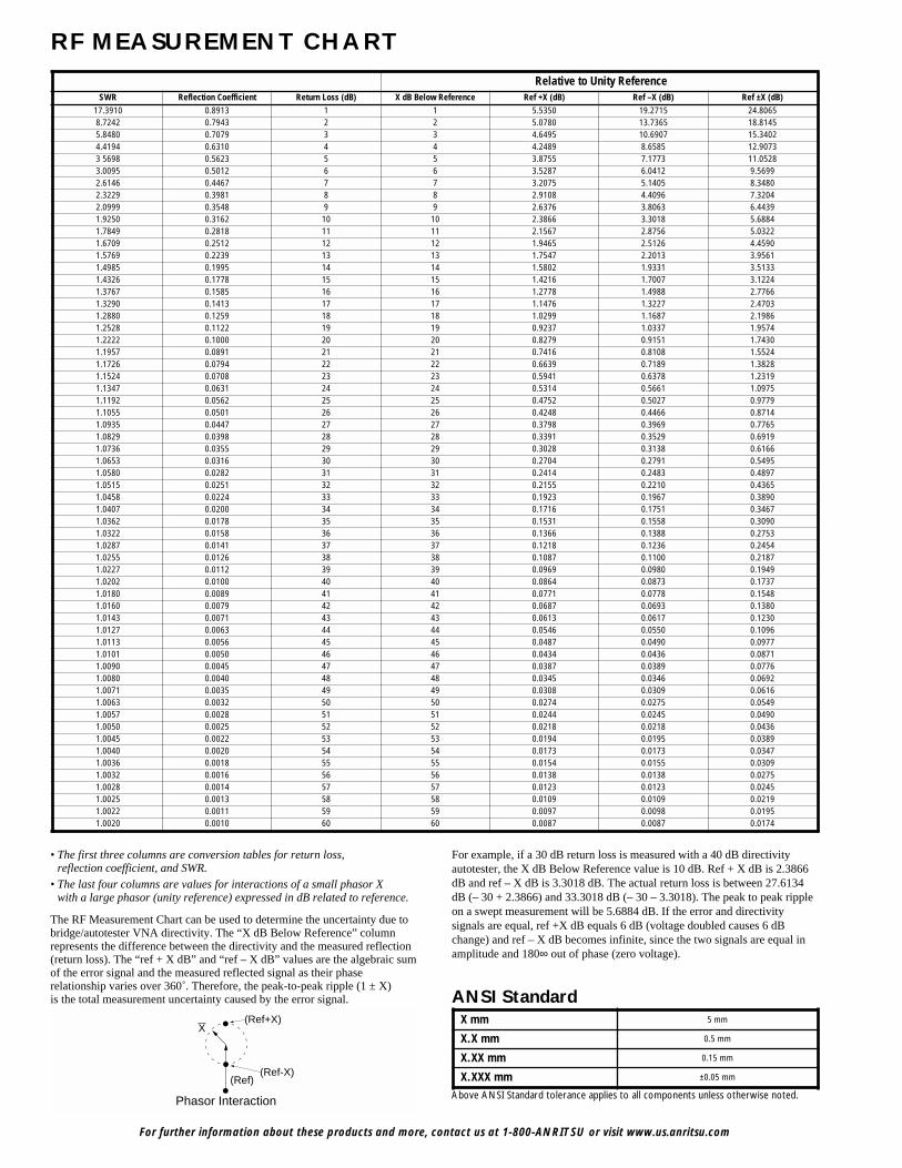
• The first three columns are conversion tables for return loss,reflection coefficient, and SWR.
• The last four columns are values for interactions of a small phasor Xwith a large phasor (unity reference) expressed in dB related to reference.
The RF Measurement Chart can be used to determine the uncertainty due tobridge/autotester VNA directivity. The “X dB Below Reference” columnrepresents the difference between the directivity and the measured reflection(return loss). The “ref + X dB” and “ref – X dB” values are the algebraic sumof the error signal and the measured reflected signal as their phaserelationship varies over 360˚. Therefore, the peak-to-peak ripple (1 ± X)is the total measurement uncertainty caused by the error signal.
For example, if a 30 dB return loss is measured with a 40 dB directivityautotester, the X dB Below Reference value is 10 dB. Ref + X dB is 2.3866dB and ref – X dB is 3.3018 dB. The actual return loss is between 27.6134dB (– 30 + 2.3866) and 33.3018 dB (– 30 – 3.3018). The peak to peak rippleon a swept measurement will be 5.6884 dB. If the error and directivitysignals are equal, ref +X dB equals 6 dB (voltage doubled causes 6 dBchange) and ref – X dB becomes infinite, since the two signals are equal inamplitude and 180∞ out of phase (zero voltage).
X(Ref+X)
(Ref-X)(Ref)
Phasor Interaction Above ANSI Standard tolerance applies to all components unless otherwise noted.
ANSI StandardX mm 5 mm
X.X mm 0.5 mm
X.XX mm 0.15 mm
X.XXX mm ±0.05 mm
Relative to Unity ReferenceSWR Reflection Coefficient Return Loss (dB) X dB Below Reference Ref +X (dB) Ref –X (dB) Ref ±X (dB)
17.3910 0.8913 1 1 5.5350 19.2715 24.80658.7242 0.7943 2 2 5.0780 13.7365 18.81455.8480 0.7079 3 3 4.6495 10.6907 15.34024.4194 0.6310 4 4 4.2489 8.6585 12.90733 5698 0.5623 5 5 3.8755 7.1773 11.05283.0095 0.5012 6 6 3.5287 6.0412 9.56992.6146 0.4467 7 7 3.2075 5.1405 8.34802.3229 0.3981 8 8 2.9108 4.4096 7.32042.0999 0.3548 9 9 2.6376 3.8063 6.44391.9250 0.3162 10 10 2.3866 3.3018 5.68841.7849 0.2818 11 11 2.1567 2.8756 5.03221.6709 0.2512 12 12 1.9465 2.5126 4.45901.5769 0.2239 13 13 1.7547 2.2013 3.95611.4985 0.1995 14 14 1.5802 1.9331 3.51331.4326 0.1778 15 15 1.4216 1.7007 3.12241.3767 0.1585 16 16 1.2778 1.4988 2.77661.3290 0.1413 17 17 1.1476 1.3227 2.47031.2880 0.1259 18 18 1.0299 1.1687 2.19861.2528 0.1122 19 19 0.9237 1.0337 1.95741.2222 0.1000 20 20 0.8279 0.9151 1.74301.1957 0.0891 21 21 0.7416 0.8108 1.55241.1726 0.0794 22 22 0.6639 0.7189 1.38281.1524 0.0708 23 23 0.5941 0.6378 1.23191.1347 0.0631 24 24 0.5314 0.5661 1.09751.1192 0.0562 25 25 0.4752 0.5027 0.97791.1055 0.0501 26 26 0.4248 0.4466 0.87141.0935 0.0447 27 27 0.3798 0.3969 0.77651.0829 0.0398 28 28 0.3391 0.3529 0.69191.0736 0.0355 29 29 0.3028 0.3138 0.61661.0653 0.0316 30 30 0.2704 0.2791 0.54951.0580 0.0282 31 31 0.2414 0.2483 0.48971.0515 0.0251 32 32 0.2155 0.2210 0.43651.0458 0.0224 33 33 0.1923 0.1967 0.38901.0407 0.0200 34 34 0.1716 0.1751 0.34671.0362 0.0178 35 35 0.1531 0.1558 0.30901.0322 0.0158 36 36 0.1366 0.1388 0.27531.0287 0.0141 37 37 0.1218 0.1236 0.24541.0255 0.0126 38 38 0.1087 0.1100 0.21871.0227 0.0112 39 39 0.0969 0.0980 0.19491.0202 0.0100 40 40 0.0864 0.0873 0.17371.0180 0.0089 41 41 0.0771 0.0778 0.15481.0160 0.0079 42 42 0.0687 0.0693 0.13801.0143 0.0071 43 43 0.0613 0.0617 0.12301.0127 0.0063 44 44 0.0546 0.0550 0.10961.0113 0.0056 45 45 0.0487 0.0490 0.09771.0101 0.0050 46 46 0.0434 0.0436 0.08711.0090 0.0045 47 47 0.0387 0.0389 0.07761.0080 0.0040 48 48 0.0345 0.0346 0.06921.0071 0.0035 49 49 0.0308 0.0309 0.06161.0063 0.0032 50 50 0.0274 0.0275 0.05491.0057 0.0028 51 51 0.0244 0.0245 0.04901.0050 0.0025 52 52 0.0218 0.0218 0.04361.0045 0.0022 53 53 0.0194 0.0195 0.03891.0040 0.0020 54 54 0.0173 0.0173 0.03471.0036 0.0018 55 55 0.0154 0.0155 0.03091.0032 0.0016 56 56 0.0138 0.0138 0.02751.0028 0.0014 57 57 0.0123 0.0123 0.02451.0025 0.0013 58 58 0.0109 0.0109 0.02191.0022 0.0011 59 59 0.0097 0.0098 0.01951.0020 0.0010 60 60 0.0087 0.0087 0.0174
For further information about these products and more, contact us at 1-800-ANRITSU or visit www.us.anritsu.com 1
TABLE OF CONTENTS
High Return Loss Connectors and CablesK Connector . . . . . . . . . . . . . . . . . . . . . . . . . . . . . . . . . . . . . . . . . . . . . . . . . . . . . . . . . . . . . . . . . . . . . . . . . . . . . . . . . . . . 4V Connector . . . . . . . . . . . . . . . . . . . . . . . . . . . . . . . . . . . . . . . . . . . . . . . . . . . . . . . . . . . . . . . . . . . . . . . . . . . . . . . . . . . . 9Integrated V Connectors . . . . . . . . . . . . . . . . . . . . . . . . . . . . . . . . . . . . . . . . . . . . . . . . . . . . . . . . . . . . . . . . . . . . . . . . . 13Connector Tools . . . . . . . . . . . . . . . . . . . . . . . . . . . . . . . . . . . . . . . . . . . . . . . . . . . . . . . . . . . . . . . . . . . . . . . . . . . . . . . . 14VP Connector . . . . . . . . . . . . . . . . . . . . . . . . . . . . . . . . . . . . . . . . . . . . . . . . . . . . . . . . . . . . . . . . . . . . . . . . . . . . . . . . . . 15RF Cables K120, V120 . . . . . . . . . . . . . . . . . . . . . . . . . . . . . . . . . . . . . . . . . . . . . . . . . . . . . . . . . . . . . . . . . . . . . . . . . . . 18
Instrumentation Grade AdaptersCoaxial Adapters K, V, K to V . . . . . . . . . . . . . . . . . . . . . . . . . . . . . . . . . . . . . . . . . . . . . . . . . . . . . . . . . . . . . . . . . . . . . . 21Precision K and V Adapters . . . . . . . . . . . . . . . . . . . . . . . . . . . . . . . . . . . . . . . . . . . . . . . . . . . . . . . . . . . . . . . . . . . . . . 21K and V Panel Adapters . . . . . . . . . . . . . . . . . . . . . . . . . . . . . . . . . . . . . . . . . . . . . . . . . . . . . . . . . . . . . . . . . . . . . . . . . . 22Calibration Grade Adapters 33 Series . . . . . . . . . . . . . . . . . . . . . . . . . . . . . . . . . . . . . . . . . . . . . . . . . . . . . . . . . . . . . . . 23Instrumentation Grade Adapters 34 Series . . . . . . . . . . . . . . . . . . . . . . . . . . . . . . . . . . . . . . . . . . . . . . . . . . . . . . . . . . 24Precision Adapter . . . . . . . . . . . . . . . . . . . . . . . . . . . . . . . . . . . . . . . . . . . . . . . . . . . . . . . . . . . . . . . . . . . . . . . . . . . . . . 24Ruggedized Adapter . . . . . . . . . . . . . . . . . . . . . . . . . . . . . . . . . . . . . . . . . . . . . . . . . . . . . . . . . . . . . . . . . . . . . . . . . . . . . 24Instrumentation Grade Adapters 35WR Series . . . . . . . . . . . . . . . . . . . . . . . . . . . . . . . . . . . . . . . . . . . . . . . . . . . . . . . . 25Instrumentation Grade Adapters 35U, 35 C Series . . . . . . . . . . . . . . . . . . . . . . . . . . . . . . . . . . . . . . . . . . . . . . . . . . . . . 28
Precision TerminationsCoaxial Terminations 26, 28, 29 Series . . . . . . . . . . . . . . . . . . . . . . . . . . . . . . . . . . . . . . . . . . . . . . . . . . . . . . . . . . . . . . 32Instrumentation Grade Attenuators . . . . . . . . . . . . . . . . . . . . . . . . . . . . . . . . . . . . . . . . . . . . . . . . . . . . . . . . . . . . . . . . 33Fixed Attenuators 41, 43 Series . . . . . . . . . . . . . . . . . . . . . . . . . . . . . . . . . . . . . . . . . . . . . . . . . . . . . . . . . . . . . . . . . . . . 33Step Attenuators 4400, 4500, 4600 Series . . . . . . . . . . . . . . . . . . . . . . . . . . . . . . . . . . . . . . . . . . . . . . . . . . . . . . . . . . . . 35
Measurement Components and AccessoriesSWR Bridges 61, 87 Series . . . . . . . . . . . . . . . . . . . . . . . . . . . . . . . . . . . . . . . . . . . . . . . . . . . . . . . . . . . . . . . . . . . . . . . . 37SWR Autotesters 97 Series, 560-97, 560-98 Series . . . . . . . . . . . . . . . . . . . . . . . . . . . . . . . . . . . . . . . . . . . . . . . . . . . . . 38SWR Autotesters 5400-6 Series . . . . . . . . . . . . . . . . . . . . . . . . . . . . . . . . . . . . . . . . . . . . . . . . . . . . . . . . . . . . . . . . . . . . 40Convertible SWR Autotesters 560-98C50A and Test Port Heads . . . . . . . . . . . . . . . . . . . . . . . . . . . . . . . . . . . . . . . . . . 41Airlines 18, 19 Series . . . . . . . . . . . . . . . . . . . . . . . . . . . . . . . . . . . . . . . . . . . . . . . . . . . . . . . . . . . . . . . . . . . . . . . . . . . . 43Open/Shorts 22 Series . . . . . . . . . . . . . . . . . . . . . . . . . . . . . . . . . . . . . . . . . . . . . . . . . . . . . . . . . . . . . . . . . . . . . . . . . . . 44Open/Shorts/Loads OSL Series . . . . . . . . . . . . . . . . . . . . . . . . . . . . . . . . . . . . . . . . . . . . . . . . . . . . . . . . . . . . . . . . . . . . 45Microwave Detectors 70, 75 Series . . . . . . . . . . . . . . . . . . . . . . . . . . . . . . . . . . . . . . . . . . . . . . . . . . . . . . . . . . . . . . . . . 46Field Replacement Diode Module . . . . . . . . . . . . . . . . . . . . . . . . . . . . . . . . . . . . . . . . . . . . . . . . . . . . . . . . . . . . . . . . . . 48Microwave Detectors 5400-71, 560-7 Series . . . . . . . . . . . . . . . . . . . . . . . . . . . . . . . . . . . . . . . . . . . . . . . . . . . . . . . . . . 49Power Sensors MA2400A/B Series . . . . . . . . . . . . . . . . . . . . . . . . . . . . . . . . . . . . . . . . . . . . . . . . . . . . . . . . . . . . . . . . . 50Power Dividers 11 Series . . . . . . . . . . . . . . . . . . . . . . . . . . . . . . . . . . . . . . . . . . . . . . . . . . . . . . . . . . . . . . . . . . . . . . . . . 53Power Dividers K240, V240 Series . . . . . . . . . . . . . . . . . . . . . . . . . . . . . . . . . . . . . . . . . . . . . . . . . . . . . . . . . . . . . . . . . . 54Power Splitters K241, V241 Series . . . . . . . . . . . . . . . . . . . . . . . . . . . . . . . . . . . . . . . . . . . . . . . . . . . . . . . . . . . . . . . . . . 55Power Splitters N241 Series . . . . . . . . . . . . . . . . . . . . . . . . . . . . . . . . . . . . . . . . . . . . . . . . . . . . . . . . . . . . . . . . . . . . . . . 56SPDT Switch . . . . . . . . . . . . . . . . . . . . . . . . . . . . . . . . . . . . . . . . . . . . . . . . . . . . . . . . . . . . . . . . . . . . . . . . . . . . . . . . . . . 57Bias Tee K250, V250 Series . . . . . . . . . . . . . . . . . . . . . . . . . . . . . . . . . . . . . . . . . . . . . . . . . . . . . . . . . . . . . . . . . . . . . . . 58Ultra-Wideband Bias Tee K251, V251 Series . . . . . . . . . . . . . . . . . . . . . . . . . . . . . . . . . . . . . . . . . . . . . . . . . . . . . . . . . 59Ultra-Wideband Bias Tee V255 . . . . . . . . . . . . . . . . . . . . . . . . . . . . . . . . . . . . . . . . . . . . . . . . . . . . . . . . . . . . . . . . . . . . 61Precision DC Blocks K261, V261 . . . . . . . . . . . . . . . . . . . . . . . . . . . . . . . . . . . . . . . . . . . . . . . . . . . . . . . . . . . . . . . . . . . 63DC Blocks V265 . . . . . . . . . . . . . . . . . . . . . . . . . . . . . . . . . . . . . . . . . . . . . . . . . . . . . . . . . . . . . . . . . . . . . . . . . . . . . . . . 65Universal Test Fixture 3680 Series . . . . . . . . . . . . . . . . . . . . . . . . . . . . . . . . . . . . . . . . . . . . . . . . . . . . . . . . . . . . . . . . . 67Limiters 1 Series . . . . . . . . . . . . . . . . . . . . . . . . . . . . . . . . . . . . . . . . . . . . . . . . . . . . . . . . . . . . . . . . . . . . . . . . . . . . . . . . 68Matching Pads 12 Series . . . . . . . . . . . . . . . . . . . . . . . . . . . . . . . . . . . . . . . . . . . . . . . . . . . . . . . . . . . . . . . . . . . . . . . . . 69VNA and VNMS Calibration Kits . . . . . . . . . . . . . . . . . . . . . . . . . . . . . . . . . . . . . . . . . . . . . . . . . . . . . . . . . . . . . . . . . . 70VNA and VNMS Verification Kits . . . . . . . . . . . . . . . . . . . . . . . . . . . . . . . . . . . . . . . . . . . . . . . . . . . . . . . . . . . . . . . . . . 72Part Number Index . . . . . . . . . . . . . . . . . . . . . . . . . . . . . . . . . . . . . . . . . . . . . . . . . . . . . . . . . . . . . . . . . . . . . . . . . . . . . . 73
For further information about these products and more, contact us at 1-800-ANRITSU or visit www.us.anritsu.com2
OUTLINE OF PRECISION MEASUREMENT COMPONENTS
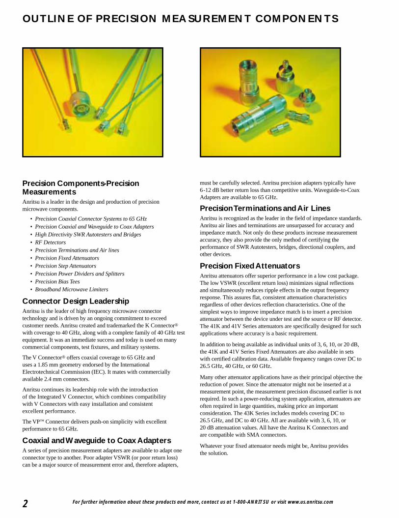
Precision Components-PrecisionMeasurementsAnritsu is a leader in the design and production of precisionmicrowave components.
• Precision Coaxial Connector Systems to 65 GHz• Precision Coaxial and Waveguide to Coax Adapters• High Directivity SWR Autotesters and Bridges• RF Detectors• Precision Terminations and Air lines• Precision Fixed Attenuators• Precision Step Attenuators• Precision Power Dividers and Splitters• Precision Bias Tees• Broadband Microwave Limiters
Connector Design LeadershipAnritsu is the leader of high frequency microwave connectortechnology and is driven by an ongoing commitment to exceedcustomer needs. Anritsu created and trademarked the K Connector®
with coverage to 40 GHz, along with a complete family of 40 GHz testequipment. It was an immediate success and today is used on manycommercial components, test fixtures, and military systems.
The V Connector® offers coaxial coverage to 65 GHz anduses a 1.85 mm geometry endorsed by the InternationalElectrotechnical Commission (IEC). It mates with commerciallyavailable 2.4 mm connectors.
Anritsu continues its leadership role with the introductionof the Integrated V Connector, which combines compatibilitywith V Connectors with easy installation and consistentexcellent performance.
The VP™ Connector delivers push-on simplicity with excellentperformance to 65 GHz.
Coaxial and Waveguide to Coax AdaptersA series of precision measurement adapters are available to adapt oneconnector type to another. Poor adapter VSWR (or poor return loss)can be a major source of measurement error and, therefore adapters,
must be carefully selected. Anritsu precision adapters typically have 6-12 dB better return loss than competitive units. Waveguide-to-CoaxAdapters are available to 65 GHz.
Precision Terminations and Air LinesAnritsu is recognized as the leader in the field of impedance standards.Anritsu air lines and terminations are unsurpassed for accuracy andimpedance match. Not only do these products increase measurementaccuracy, they also provide the only method of certifying theperformance of SWR Autotesters, bridges, directional couplers, andother devices.
Precision Fixed AttenuatorsAnritsu attenuators offer superior performance in a low cost package.The low VSWR (excellent return loss) minimizes signal reflectionsand simultaneously reduces ripple effects in the output frequencyresponse. This assures flat, consistent attenuation characteristicsregardless of other devices reflection characteristics. One of thesimplest ways to improve impedance match is to insert a precisionattenuator between the device under test and the source or RF detector.The 41K and 41V Series attenuators are specifically designed for suchapplications where accuracy is a basic requirement.
In addition to being available as individual units of 3, 6, 10, or 20 dB,the 41K and 41V Series Fixed Attenuators are also available in setswith certified calibration data. Available frequency ranges cover DC to26.5 GHz, 40 GHz, or 60 GHz.
Many other attenuator applications have as their principal objective thereduction of power. Since the attenuator might not be inserted at ameasurement point, the measurement precision discussed earlier is notrequired. In such a power-reducing system application, attenuators areoften required in large quantities, making price an importantconsideration. The 43K Series includes models covering DC to26.5 GHz, and DC to 40 GHz. All are available with 3, 6, 10, or20 dB attenuation values. All have the Anritsu K Connectors andare compatible with SMA connectors.
Whatever your fixed attenuator needs might be, Anritsu providesthe solution.

For further information about these products and more, contact us at 1-800-ANRITSU or visit www.us.anritsu.com 3
Precision Step AttenuatorsAnritsu offers low loss, high precision step attenuators. Theseprogrammable step attenuators are available with 10 dB steps from0 to 70 dB or 0 to 110 dB ranges. DC to 40 GHz frequency rangeensures the broadest attenuation and frequency coverage available.Contact Anritsu for needs above 40 GHz.
Precision Power Dividers and SplittersAnritsu produces precision V Connector® dividers and splittersto 60 GHz and precision K Connector® dividers and splittersto 40 GHz.
All Anritsu power dividers are 3-resistor symmetrical designswith excellent amplitude and phase tracking. Anritsu powersplitters are 2-resistor designs, used to accurately split signalsfor ratio measurements.
Precision Bias TeesAnritsu Bias Tees are used to combine DC and RF for active devicemeasurements. Low RF throughline loss and low SWR ensurenegligible effect on measurements from 50 kHz to 60 GHz.
Broadband Microwave LimitersAnritsu broadband microwave limiters provide the widest frequencyrange available in a limiter. Designed to protect sensitive microwaveequipment, these limiters incorporate unique single-side limiting toprovide soft limiting characteristics over 10 MHz to 26.5 GHz.
High Directivity SWR Autotestersand BridgesSWR Autotesters and SWR Bridges are directional measurementdevices that separate the incident and the reflected signals of a deviceunder test. The reflected component can then be compared to theincident signal to determine the difference between the device’simpedance and its characteristic impedance.
An SWR bridge has a precision termination inside the bridge,eliminating the need for an external reference. An autotester furthersimplifies the user interface by incorporating a detector into the RFoutput that provides a DC output proportional to the DUT mismatch.
The directivity of the SWR Autotester or bridge is the measure of howwell the incident and reflected signals can be separated. For example,40 dB directivity means that the error signal in the output is 40 dBbelow the reflected signal to be measured.
Anritsu’s high directivity bridges and autotesters set the standards forreflection measurements. High directivity translates to accuratemeasurements. Anritsu high directivity bridges are available for GPC-7, 50 Ω and 75 Ω Type N. High directivity autotestersare available with GPC-7, Type N, and SMA, 3.5, K Connectors®,
and V Connectors®.
RF DetectorsJust as directivity is the principal error contributor in reflectionmeasurements, the impedance match of the signal source and RFdetector is a significant error contributor intransmission measurements.
Anritsu offers a complete line of coaxial RF detectors covering from100 kHz to 50 GHz with the lowest SWR available. The excellentimpedance match of the detectors, along with that of the test porton the SWR Autotesters and bridges, minimize errors when makingsimultaneous transmission and measurements.
Calibration and Verification KitsAnritsu offers calibration kits which contain all the precisioncomponents and tools required to calibrate an Anritsu VNA in aconnector style of your choice.
SpecialsAnritsu also manufactures assemblies and components to meetspecific customer requirements in both coaxial and waveguidestructures. These include such components as Connectors, Bias Tee,Step Attenuator, Detector, Power Sensors, Waveguide, CoaxialAdapters, and RF Cables etc.
When requesting quotations on special assemblies, as a minimumplease provide this information: frequency range, electricalcharacteristics, mechanical details and outline dimensions if any.

The K Connector® is a precision coaxial connector system thatoperates up to 40 GHz. It is compatible with SMA, WSMA, and3.5 mm connectors. It is well suited to applications in components,systems, or instrumentation.
K Connector® features• Excellent performance up to 40 GHz• Performance exceeding SMA below 18 GHz• Superior reliability• Compatibility with SMA, WSMA, and 3.5 mm• Complete testability on existing network analyzers
Exceptional reliability and repeatabilityMicrowave connector reliability is affected by insertion force,outer conductor strength, stress relief while mating, and matingalignment. The K Connector exhibits exceptional performancein all of these areas.
For proper seating, a standard SMA or 3.5 mm connector canrequire in excess of 27N* of insertion force, In contrast, theK Connector requires only 2.3N*. The reduced wear on thefemale center conductor improves reliability. In addition, theK Connectors outer conductor is four times thicker than thatof SMA. Taken together, the lower insertion force and the thickerwall offer more reliable connections than available from an SMAconnector. Life tests show that the K Connector makes greaterthan 10,000 connections with negligible change in electricalcharacteristics.
*Force is measured in Newtons (N).
For further information about these products and more, contact us at 1-800-ANRITSU or visit www.us.anritsu.com4
K CONNECTOR®
DC to 40 GHz
All K Connectors, including the cable connectors, incorporatea feature that eliminates a major cause of connector failure;misalignment of the male pin with respect to the female contacts.To solve the problems the K Connector male pin is deliberatelymade shorter than the SMA or 3.5 mm pin. With this arrangement,the outer housing is properly aligned prior to the mating of thecenter conductors. Thus a proper, non-destructive alignment beforemating is ensured.
The effect of pin gap on a connection is often overlooked, but is thedominant source of error in many connection systems. Pin gap isthe short length of smaller diameter caused when a connector pairis mated. Pin gap causes a discontinuity at the connector interface.The K Connector has considerably less susceptibility to pin gap thaneither SMA or 3.5 mm connectors.
Many connector manufacturers specify connector performanceassuming no pin gap, an unrealistic assumption. K Connectorsare specified assuming pin gap to be at its maximum tolerance,to provide you the assurance of real-world specifications.
CompatibilityThe K Connector interfaces electrically and mechanicallywith 3.5 mm connectors, including SMA and 3.5 mm withoutdegradation in performance.
Launcher designAt the heart of the K Connector product line are the launchers.As their name implies, the launchers “launch” (make the transition)from a microwave circuit (microstrip, suspended substrate, stripline,or coplanar waveguide) to a coaxial connector and an outsidetransmission line. The key to making the transition withoutcompromising electrical and mechanical objectives is the glassbead in the launcher assembly.
SMA3.5
0
-10
-20
-30
-40Pin
Gap
Ret
urn
Loss
(dB
)
Frequency (GHz)20 30 40
K
Pin Gap
MaleCenter
Pin
FemaleCenter
Pin
SMA/APC-3.5
K Connector
Shortened Male Pin Eliminates Damage to Female K Connector
Effect of Pin Gap
For further information about these products and more, contact us at 1-800-ANRITSU or visit www.us.anritsu.com 5
K CONNECTOR®
DC to 40 GHz
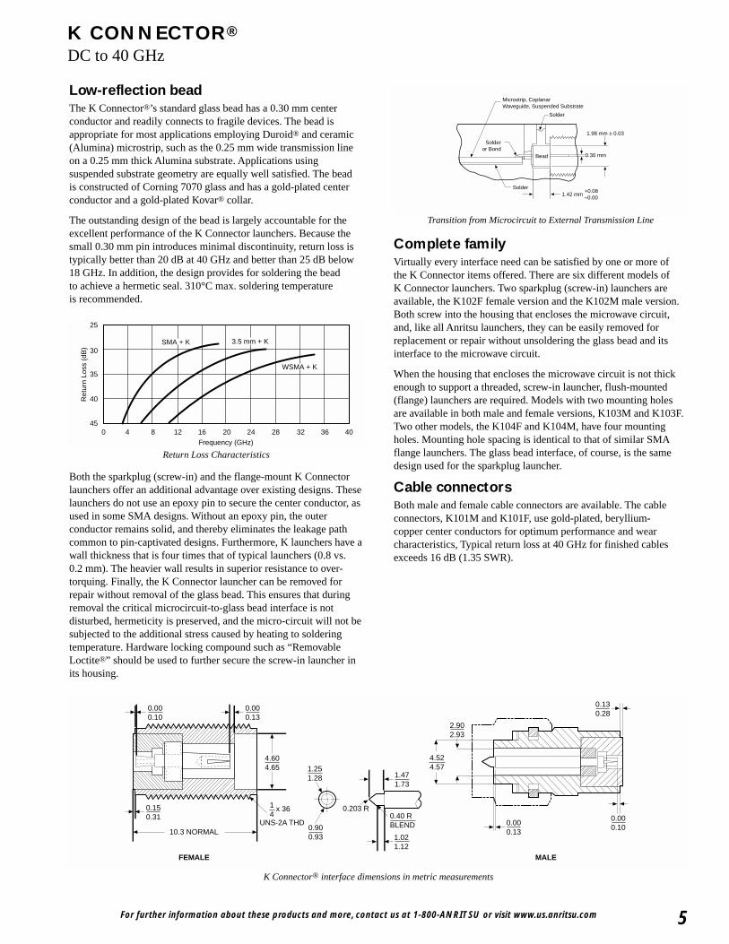
Low-reflection beadThe K Connector®’s standard glass bead has a 0.30 mm centerconductor and readily connects to fragile devices. The bead isappropriate for most applications employing Duroid® and ceramic(Alumina) microstrip, such as the 0.25 mm wide transmission lineon a 0.25 mm thick Alumina substrate. Applications usingsuspended substrate geometry are equally well satisfied. The beadis constructed of Corning 7070 glass and has a gold-plated centerconductor and a gold-plated Kovar® collar.
The outstanding design of the bead is largely accountable for theexcellent performance of the K Connector launchers. Because thesmall 0.30 mm pin introduces minimal discontinuity, return loss istypically better than 20 dB at 40 GHz and better than 25 dB below18 GHz. In addition, the design provides for soldering the beadto achieve a hermetic seal. 310°C max. soldering temperatureis recommended.
Both the sparkplug (screw-in) and the flange-mount K Connectorlaunchers offer an additional advantage over existing designs. Theselaunchers do not use an epoxy pin to secure the center conductor, asused in some SMA designs. Without an epoxy pin, the outerconductor remains solid, and thereby eliminates the leakage pathcommon to pin-captivated designs. Furthermore, K launchers have awall thickness that is four times that of typical launchers (0.8 vs.0.2 mm). The heavier wall results in superior resistance to over-torquing. Finally, the K Connector launcher can be removed forrepair without removal of the glass bead. This ensures that duringremoval the critical microcircuit-to-glass bead interface is notdisturbed, hermeticity is preserved, and the micro-circuit will not besubjected to the additional stress caused by heating to solderingtemperature. Hardware locking compound such as “RemovableLoctite®” should be used to further secure the screw-in launcher inits housing.
Complete familyVirtually every interface need can be satisfied by one or more ofthe K Connector items offered. There are six different models ofK Connector launchers. Two sparkplug (screw-in) launchers areavailable, the K102F female version and the K102M male version.Both screw into the housing that encloses the microwave circuit,and, like all Anritsu launchers, they can be easily removed forreplacement or repair without unsoldering the glass bead and itsinterface to the microwave circuit.
When the housing that encloses the microwave circuit is not thickenough to support a threaded, screw-in launcher, flush-mounted(flange) launchers are required. Models with two mounting holesare available in both male and female versions, K103M and K103F.Two other models, the K104F and K104M, have four mountingholes. Mounting hole spacing is identical to that of similar SMAflange launchers. The glass bead interface, of course, is the samedesign used for the sparkplug launcher.
Cable connectorsBoth male and female cable connectors are available. The cableconnectors, K101M and K101F, use gold-plated, beryllium-copper center conductors for optimum performance and wearcharacteristics, Typical return loss at 40 GHz for finished cablesexceeds 16 dB (1.35 SWR).
0.000.10
4.524.57
2.902.93
0.130.28
0.000.10
0.000.13
0.000.13
1.021.12
0.900.93
0.40 RBLEND
4.604.65 1.25
1.28 1.471.73
0.150.31
10.3 NORMAL
0.203 R
FEMALE MALE
UNS-2A THD
1 x 364
K Connector® interface dimensions in metric measurements
Frequency (GHz)
Ret
urn
Loss
(dB
)
25
30
35
40
450 4 8 12 16 2420 28 32 36 40
WSMA + K
3.5 mm + KSMA + K
Return Loss Characteristics
Solder
Solderor Bond
Solder
0.30 mm
1.42 mm
1.98 mm ± 0.03
Bead
Microstrip, CoplanarWaveguide, Suspended Substrate
+0.08–0.00
Transition from Microcircuit to External Transmission Line
For further information about these products and more, contact us at 1-800-ANRITSU or visit www.us.anritsu.com6
K CONNECTOR®
DC to 40 GHz
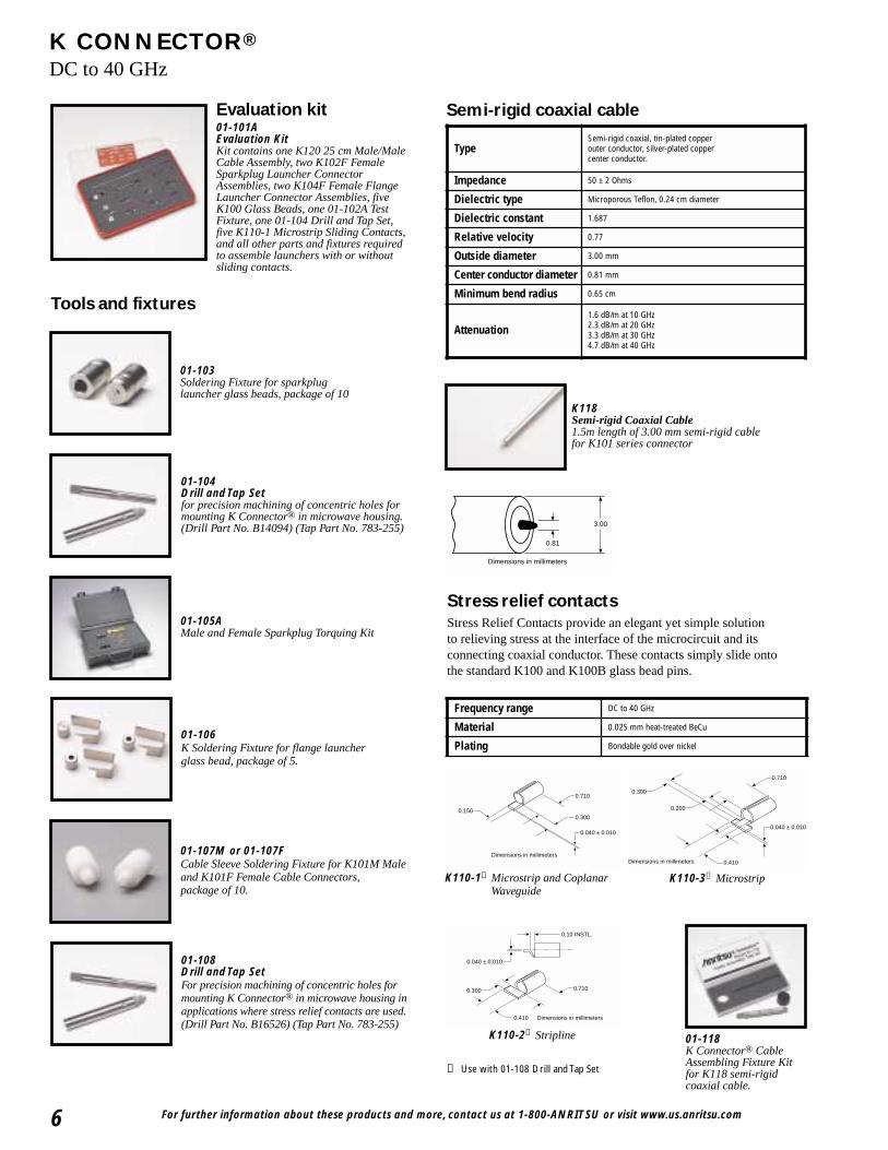
Evaluation kit01-101AEvaluation KitKit contains one K120 25 cm Male/MaleCable Assembly, two K102F FemaleSparkplug Launcher ConnectorAssemblies, two K104F Female FlangeLauncher Connector Assemblies, fiveK100 Glass Beads, one 01-102A TestFixture, one 01-104 Drill and Tap Set,five K110-1 Microstrip Sliding Contacts,and all other parts and fixtures requiredto assemble launchers with or withoutsliding contacts.
01-104Drill and Tap Setfor precision machining of concentric holes formounting K Connector® in microwave housing.(Drill Part No. B14094) (Tap Part No. 783-255)
01-105AMale and Female Sparkplug Torquing Kit
01-106K Soldering Fixture for flange launcher glass bead, package of 5.
01-107M or 01-107FCable Sleeve Soldering Fixture for K101M Maleand K101F Female Cable Connectors,package of 10.
01-108Drill and Tap SetFor precision machining of concentric holes formounting K Connector® in microwave housing inapplications where stress relief contacts are used.(Drill Part No. B16526) (Tap Part No. 783-255)
01-118K Connector® Cable Assembling Fixture Kitfor K118 semi-rigidcoaxial cable.
3.00
0.81
Dimensions in millimeters
K118Semi-rigid Coaxial Cable1.5m length of 3.00 mm semi-rigid cablefor K101 series connector
Stress relief contactsStress Relief Contacts provide an elegant yet simple solutionto relieving stress at the interface of the microcircuit and itsconnecting coaxial conductor. These contacts simply slide ontothe standard K100 and K100B glass bead pins.
0.150
0.710
0.300
0.040 ± 0.010
Dimensions in millimeters
0.300
0.410
0.710
0.10 INSTL.
0.040 ± 0.010
Dimensions in millimeters
0.040 ± 0.010
0.710
0.300
0.200
0.410Dimensions in millimeters
K110-1➀ Microstrip and CoplanarWaveguide
K110-3➀ Microstrip
K110-2➀ Stripline
Semi-rigid coaxial cable
Tools and fixtures
01-103Soldering Fixture for sparkplug launcher glass beads, package of 10
TypeSemi-rigid coaxial, tin-plated copper outer conductor, silver-plated copper center conductor.
Impedance 50 ± 2 Ohms
Dielectric type Microporous Teflon, 0.24 cm diameter
Dielectric constant 1.687
Relative velocity 0.77
Outside diameter 3.00 mm
Center conductor diameter 0.81 mm
Minimum bend radius 0.65 cm
Attenuation1.6 dB/m at 10 GHz2.3 dB/m at 20 GHz3.3 dB/m at 30 GHz4.7 dB/m at 40 GHz
Frequency range DC to 40 GHz
Material 0.025 mm heat-treated BeCu
Plating Bondable gold over nickel
➀ Use with 01-108 Drill and Tap Set

For further information about these products and more, contact us at 1-800-ANRITSU or visit www.us.anritsu.com 7
K CONNECTOR®
DC to 40 GHz
3.18
0.74
1.40
1.93
0.300 DIA.Dimensions in millimeters
3.18
0.74
1.40
1.93
0.300 DIA.Dimensions in millimeters
K100➀➁
Glass Beads for K102, K103, andK104 connectors
K100B➀➁
High Hermeticity* GlassBeads for K102, K103,and K104 connectors
7.9 HEX
3.04 for K101M2.26 for K101M-085
4.55 for K101M3.05 for K101M-0858.4
10.9 Dimensions in millimeters
K101M➃
K Male In-Line CableConnector, DC-40 GHzfor 0.118 cable
K101M-085➃
for 0.085 cable
7.9 HEX
3.04
4.6710.9
12.9
1/4 - 36 THD
Dimensions in millimeters
K101F➄
K Female In-Line CableConnector, DC-40 GHz for0.118 cable
7.9 HEX16.2
12.0
4.65
5.33
1/4 - 36 THD
0.13 0.28
Dimensions in millimeters
K102M➂
K Male SparkplugLauncher Connector,DC-40 GHz
0.150.30
1/4 - 36 THD
10.4 Dimensions in millimeters
4.65
5.33
∅ 5.33
K102F➂
K Female SparkplugLauncher Connector,DC-40 GHz
*Glass Bead Hermeticity Spec: Hermetic to 1 x 10⁻⁸ std cc He/sec at 1 atm differential
12.2
5.7
15.9
2.6 DIA. (2 PLACES)
9.6
4.14
1.7
0.050.20
1/4 - 36 THD
Dimensions in millimeters
∅ 5.33
K103FK Female FlangeLauncher, two-hole,DC-40 GHz
Launchers and cable connectors
6.60
15.912.2
2.6 DIA. (2 PLACES)
13.1
4.14
1.7
0.050.20
7.9 HEX
Dimensions in millimeters
K103MK Male Flange Launcher,two-hole, DC-40 GHz
Return loss (launchers only) 15 dB up to 40 GHz
Coupling nut tightening torque 1.36 N-m max
Material Passivated stainless steel with heat-treated berylliumcopper center conductors
Pin depth 0.000 to -0.13 mm for male and female connectors
Temperature range -55°C to +125°C (200°C available; contact factory)
➀ Use with 01-104 or 01-108 Drill and Tap Sets➁ Use with 01-103 or 01-106 Soldering Fixtures➂ Use with 01-105A Male and Female Sparkplug
Torquing Kit➃ Use with 01-107M Cable Sleeve Fixture➄ Use with 01-107F Cable Sleeve Fixture
For further information about these products and more, contact us at 1-800-ANRITSU or visit www.us.anritsu.com8
K CONNECTOR®
DC to 40 GHz
2.6 DIA. (4 PLACES)
8.6 TYP
12.7 SQ.9.6
4.14
1.7 ∅ 5.33
0.050.20
1/4 - 36 THD
Dimensions in millimeters
K104FK Female Flange Launcher,four-hole, DC-40 GHz
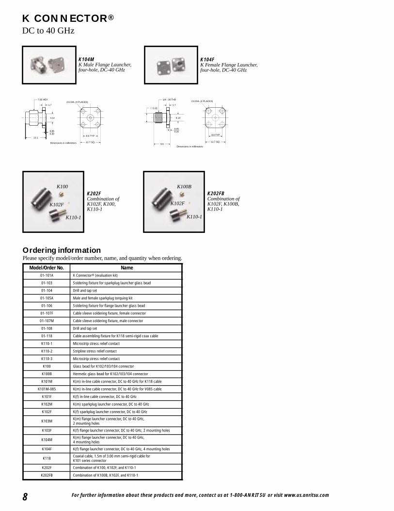
Ordering informationPlease specify model/order number, name, and quantity when ordering.
K110-1
K100B
K102F
K202FCombination ofK102F, K100,K110-1
K202FBCombination ofK102F, K100B,K110-1
K100
K102F
K110-1
13.1
4.14
1.7
0.050.20
7.92 HEX
12.7 SQ.
8.6 TYP
2.6 DIA. (4 PLACES)
Dimensions in millimeters
K104MK Male Flange Launcher,four-hole, DC-40 GHz
Model/Order No. Name01-101A K Connector® (evaluation kit)
01-103 Soldering fixture for sparkplug launcher glass bead
01-104 Drill and tap set
01-105A Male and female sparkplug torquing kit
01-106 Soldering fixture for flange launcher glass bead
01-107F Cable sleeve soldering fixture, female connector
01-107M Cable sleeve soldering fixture, male connector
01-108 Drill and tap set
01-118 Cable assembling fixture for K118 semi-rigid coax cable
K110-1 Microstrip stress relief contact
K110-2 Stripline stress relief contact
K110-3 Microstrip stress relief contact
K100 Glass bead for K102/103/104 connector
K100B Hermetic glass bead for K102/103/104 connector
K101M K(m) in-line cable connector, DC to 40 GHz for K118 cable
K101M-085 K(m) in-line cable connector, DC to 40 GHz for V085 cable
K101F K(f) in-line cable connector, DC to 40 GHz
K102M K(m) sparkplug launcher connector, DC to 40 GHz
K102F K(f) sparkplug launcher connector, DC to 40 GHz
K103M K(m) flange launcher connector, DC to 40 GHz, 2 mounting holes
K103F K(f) flange launcher connector, DC to 40 GHz, 2 mounting holes
K104M K(m) flange launcher connector, DC to 40 GHz, 4 mounting holes
K104F K(f) flange launcher connector, DC to 40 GHz, 4 mounting holes
K118 Coaxial cable, 1.5m of 3.00 mm semi-rigid cable for K101 series connector
K202F Combination of K100, K102F, and K110-1
K202FB Combination of K100B, K102F, and K110-1
For further information about these products and more, contact us at 1-800-Anritsu or visit www.us.anritsu.com 9
V CONNECTOR®
DC to 65 GHz
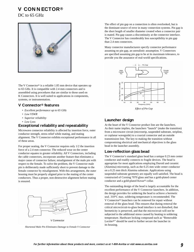
The V Connector® is a reliable 1.85 mm device that operates upto 65 GHz. It is compatible with 2.4 mm connectors and isassembled using procedures that are similar to those used onK Connectors. It is well suited to applications in components,systems, or instrumentation.
V Connector® features• Excellent performance up to 65 GHz• Low VSWR• Superior reliability• Low Loss
Exceptional reliability and repeatabilityMicrowave connector reliability is affected by insertion force, outerconductor strength, stress relief while mating, and matingalignment. The V Connector exhibits exceptional performance in allof these areas.
For proper seating, the V Connector requires only 1/2 the insertionforce of a 2.4 mm connector. The reduced wear on the centerconductor equates to greater reliability. All V Connectors, includingthe cable connectors, incorporate another feature that eliminates amajor cause of connector failure; misalignment of the male pin withrespect to the female. To solve the problem, the V Connector malepin is deliberately made sufficiently short to prevent damage to thefemale connector by misalignment. With this arrangement, the outerhousing must be properly aligned prior to the mating of the centerconductors. Thus a proper, non-destructive alignment before matingis ensured.
The effect of pin gap on a connection is often overlooked, but isthe dominant source of error in many connection systems. Pin gap isthe short length of smaller diameter created when a connector pairis mated. Pin gap causes a discontinuity at the connector interface.The V Connector has considerably less susceptibility to pin gapthan 2.4 mm connectors.
Many connector manufacturers specify connector performanceassuming no pin gap, an unrealistic assumption. V Connectorsare specified assuming pin gap to be at its maximum tolerance, toprovide you the assurance of real-world specifications.
-10
-20
-30
-40Pin
Gap
Ret
urn
Loss
(dB
)
10 20Frequency (GHz)
30 40 50 60 70
Pin Gap
MaleCenter
Pin
FemaleCenter
Pin
2.4 mm
V
Effect of Pin Gap
V Connector
Shortened Male Pin Eliminates Damage to Female V Connector
Launcher designAt the heart of the V Connector product line are the launchers.As their name implies, the launchers “launch” (make the transition)from a microwave circuit (microstrip, suspended substrate, stripline,or coplanar waveguide) to a coaxial connector and an outsidetransmission line. The key to making the transition withoutcompromising electrical and mechanical objectives is the glassbead in the launcher assembly.
Low-reflection glass beadThe V Connector’s standard glass bead has a unique 0.23 mm centerconductor and readily connects to fragile devices. The bead isappropriate for most applications employing Duroid and ceramic(Alumina) microstrip, such as the 0.25 mm wide center conductoron a 0.25 mm thick Alumina substrate. Applications usingsuspended substrate geometry are equally well satisfied. The bead isconstructed of Corning 7070 glass and has a gold-plated centerconductor and a gold-plated Kovar® collar.
The outstanding design of the bead is largely accountable for theexcellent performance of the V Connector launchers. In addition,the design provides for soldering the bead to achieve a hermeticseal. 310°C max. soldering temperature is recommended. TheV Connector® launchers can be removed for repair withoutremoval of the glass bead. This ensures that during removal thecritical microcircuit-to-glass bead interface is not disturbed, thathermeticity is preserved, and that the microcircuit will not besubjected to the additional stress caused by heating to solderingtemperature. Hardware locking compound such as “RemovableLoctite®” should be used to further secure the launcher inits housing.
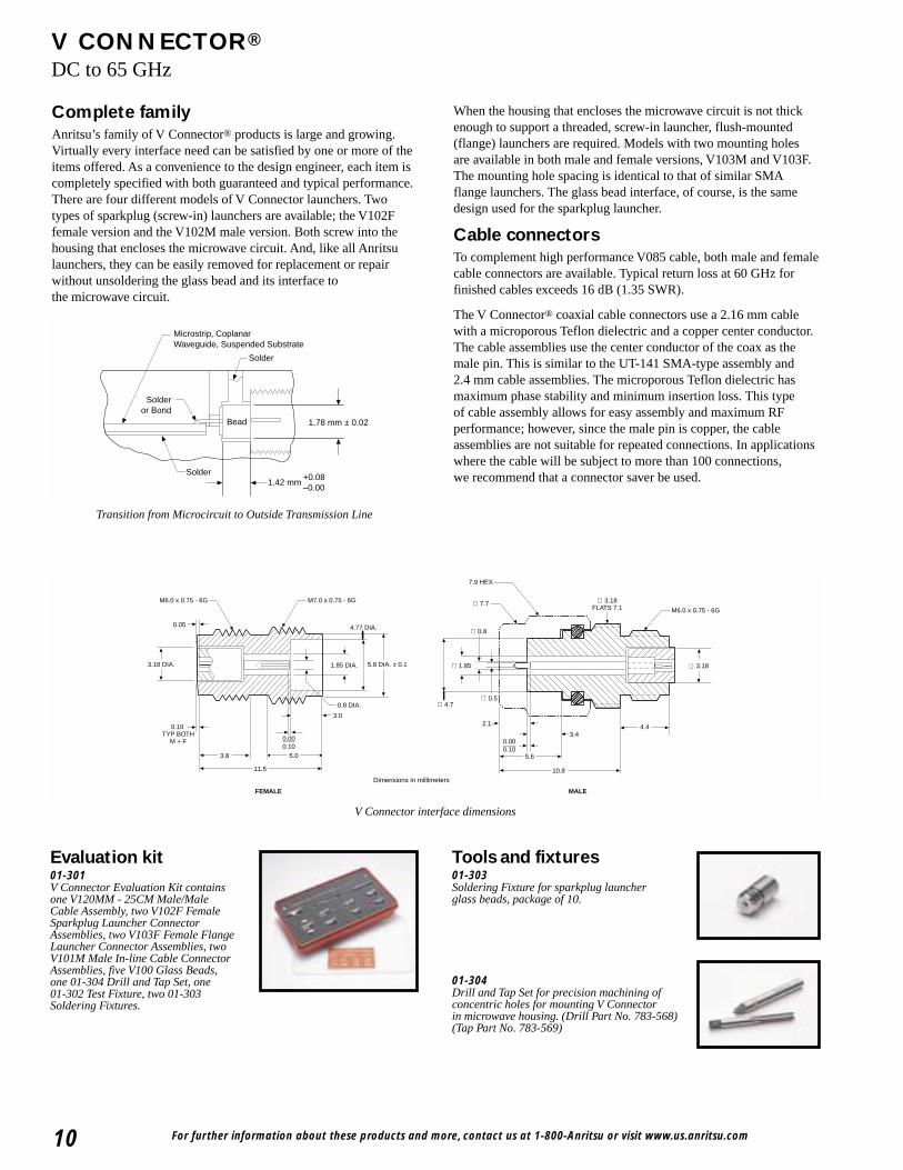
Complete familyAnritsu’s family of V Connector® products is large and growing.Virtually every interface need can be satisfied by one or more of theitems offered. As a convenience to the design engineer, each item iscompletely specified with both guaranteed and typical performance.There are four different models of V Connector launchers. Twotypes of sparkplug (screw-in) launchers are available; the V102Ffemale version and the V102M male version. Both screw into thehousing that encloses the microwave circuit. And, like all Anritsulaunchers, they can be easily removed for replacement or repairwithout unsoldering the glass bead and its interface tothe microwave circuit.
For further information about these products and more, contact us at 1-800-Anritsu or visit www.us.anritsu.com10
V CONNECTOR®
DC to 65 GHz
Solder
Solderor Bond
Solder
Bead
Microstrip, CoplanarWaveguide, Suspended Substrate
1.42 mm
1.78 mm ± 0.02
+0.08–0.00
Transition from Microcircuit to Outside Transmission Line
FEMALE MALE
M6.0 x 0.75 - 6G M7.0 x 0.75 - 6G
M6.0 x 0.75 - 6G
1.85 DIA. ∅ 1.855.8 DIA. ± 0.1
∅ 0.5
3.18 DIA.
4.77 DIA.
∅ 4.7
∅ 3.18
∅ 3.18FLATS 7.1
0.8 DIA.
∅ 0.8
∅ 7.7
0.05
3.0
5.0
10.8
5.6
2.1
7.9 HEX
3.44.4
3.8
0.10 TYP BOTH
M + F
11.5
0.000.10
0.000.10
Dimensions in millimeters
V Connector interface dimensions
Evaluation kit01-301V Connector Evaluation Kit containsone V120MM - 25CM Male/MaleCable Assembly, two V102F FemaleSparkplug Launcher ConnectorAssemblies, two V103F Female FlangeLauncher Connector Assemblies, twoV101M Male In-line Cable ConnectorAssemblies, five V100 Glass Beads,one 01-304 Drill and Tap Set, one 01-302 Test Fixture, two 01-303Soldering Fixtures.
Tools and fixtures01-303Soldering Fixture for sparkplug launcherglass beads, package of 10.
01-304Drill and Tap Set for precision machining ofconcentric holes for mounting V Connectorin microwave housing. (Drill Part No. 783-568)(Tap Part No. 783-569)
When the housing that encloses the microwave circuit is not thickenough to support a threaded, screw-in launcher, flush-mounted(flange) launchers are required. Models with two mounting holesare available in both male and female versions, V103M and V103F.The mounting hole spacing is identical to that of similar SMAflange launchers. The glass bead interface, of course, is the samedesign used for the sparkplug launcher.
Cable connectorsTo complement high performance V085 cable, both male and femalecable connectors are available. Typical return loss at 60 GHz forfinished cables exceeds 16 dB (1.35 SWR).
The V Connector® coaxial cable connectors use a 2.16 mm cablewith a microporous Teflon dielectric and a copper center conductor.The cable assemblies use the center conductor of the coax as themale pin. This is similar to the UT-141 SMA-type assembly and2.4 mm cable assemblies. The microporous Teflon dielectric hasmaximum phase stability and minimum insertion loss. This typeof cable assembly allows for easy assembly and maximum RFperformance; however, since the male pin is copper, the cableassemblies are not suitable for repeated connections. In applicationswhere the cable will be subject to more than 100 connections,we recommend that a connector saver be used.

For further information about these products and more, contact us at 1-800-Anritsu or visit www.us.anritsu.com 11
V CONNECTOR®
DC to 65 GHz
01-105AK and V Connector® Male and FemaleSparkplug Torquing Kit.
Semi-rigid coaxial cable
Launchers and cable connectors
V085semirigid coaxial cable1.5m length of 2.16 mm semirigid cable for V101 series connector
2.16
0.51
Dimensions in millimeters
2.791.40
1.72
0.240 DIA.0.60
Dimensions in millimeters
V100➀➁
Glass Beads for V102,and V103 connectors(package of 5)
01-309V Connector Cable Assembling Fixturefor V085 semi-rigid cable.
01-306Soldering Fixture for flange launcher glassbead, package of 5.
01-308Drill and Tap set for precision machining ofconcentric holes for mounting V Connector inmicrowave housing in applications wherestress-relief contacts are used.
01-307M or 01-307FCable Sleeve Soldering Fixture for V101MMale and V101F Female Cable Connectors,package of 10.
Stress relief contactsStress Relief Contacts provide an elegant yet simple solutionto relieving stress at the interface of the microcircuit and itsconnecting coaxial conductor. These contacts simply slide onto thestandard glass bead pins and can be soldered, bonded or parallel-gapwelded to a circuit trace.
0.160
0.640
0.250 mm
0.040 ± 0.010
Dimensions in millimeters
V110-1Microstrip and Coplanar Waveguidewhen using the V110-1, use 01-308Drill and Tap set to make therequired concentric holes.
2.791.40
1.72
0.240 DIA.0.60
Dimensions in millimeters
V100B➀➁
High Hermeticity*Glass Beads for V102,and V103 connectors (package of 5)
*Glass Bead Hermeticity Spec: Hermetic to 1 x 10⁻⁸ std cc He/sec at 1 atm differential
Frequency range DC to 67 GHz
Material 0.025 mm heat-treated BeCu
Plating Bondable gold
Packaging Lots of 25
Return loss (launchers only) 13 dB up to 60 GHz
Coupling nut tightening torque 1.36 N-m max
Material Passivated stainless steel with heat-treated beryllium copper center conductors
Pin depth 0.000 to -0.130 mm for male and female connectors
Temperature range -55°C to +125°C
TypeSemi-rigid coaxial, tin-plated copper outer conductor, silver-plated copper center conductor.
Impedance 50 ± 2 Ohms
Dielectric type Microporous Teflon, 0.14 cm diameter
Dielectric constant 1.687
Relative velocity 0.77
Outside diameter 2.16 mm
Center conductor diameter 0.51 mm
Minimum bend radius 0.65 cm
Attenuation
2.3 dB/m at 10 GHz3.6 dB/m at 20 GHz4.3 dB/m at 30 GHz5.2 dB/m at 40 GHz7.2 dB/m at 60 GHz
➀ Use with 01-303 or 01-306 Soldering Fixtures➁ Use with 01-304 or 01-308 Drill and Tap Sets
For further information about these products and more, contact us at 1-800-Anritsu or visit www.us.anritsu.com12
V CONNECTOR®
DC to 65 GHz
12.215.9
5.7
2.6 DIA. (2 PLACES)M7 x 0.75 - 6G
1.7
∅ 3.20
∅ 5.8
11.3
0.10
Dimensions in millimeters
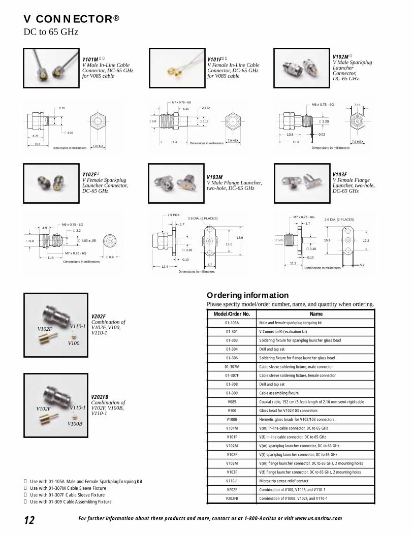
V103FV Female FlangeLauncher, two-hole,DC-65 GHz
V202FCombination ofV102F, V100,V110-1
V202FBCombination ofV102F, V100B,V110-1
V110-1
V110-1V102F
V100
V100B
V102F
Ordering informationPlease specify model/order number, name, and quantity when ordering.
2.26
∅ 4.068.76
10.17.9 HEX
Dimensions in millimeters
V101M➁➃
V Male In-Line CableConnector, DC-65 GHzfor V085 cable
7.9 HEX11.4
M7 x 0.75 - 6G
∅ 3.18
2.3 ID
∅ 5.8
6.35
Dimensions in millimeters 7.9 HEX
∅ 3.20
7.11
0.02
M6 x 0.75 - 6G
15.3
10.8
Dimensions in millimeters
V102M➀
V Male SparkplugLauncherConnector,DC-65 GHz
M6 x 0.75 - 6G
M7 x 0.75 - 6G11.5
4.9
∅ 4.83 ± .05
∅ 6.9
∅ 5.8
∅ 3.2
Dimensions in millimeters
V102F➀
V Female SparkplugLauncher Connector,DC-65 GHz
15.9
12.2
5.7
2.6 DIA. (2 PLACES)
1.7
0.10
12.4
∅ 3.20
7.9 HEX
Dimensions in millimeters
V101F➂➃
V Female In-Line CableConnector, DC-65 GHzfor V085 cable
V103MV Male Flange Launcher,two-hole, DC-65 GHz
Model/Order No. Name
01-105A Male and female sparkplug torquing kit
01-301 V Connector® (evaluation kit)
01-303 Soldering fixture for sparkplug launcher glass bead
01-304 Drill and tap set
01-306 Soldering fixture for flange launcher glass bead
01-307M Cable sleeve soldering fixture, male connector
01-307F Cable sleeve soldering fixture, female connector
01-308 Drill and tap set
01-309 Cable assembling fixture
V085 Coaxial cable, 152 cm (5 feet) length of 2.16 mm semi-rigid cable
V100 Glass bead for V102/103 connectors
V100B Hermetic glass beads for V102/103 connectors
V101M V(m) in-line cable connector, DC to 65 GHz
V101F V(f) in-line cable connector, DC to 65 GHz
V102M V(m) sparkplug launcher connector, DC to 65 GHz
V102F V(f) sparkplug launcher connector, DC to 65 GHz
V103M V(m) flange launcher connector, DC to 65 GHz, 2 mounting holes
V103F V(f) flange launcher connector, DC to 65 GHz, 2 mounting holes
V110-1 Microstrip stress relief contact
V202F Combination of V100, V102F, and V110-1
V202FB Combination of V100B, V102F, and V110-1
➀ Use with 01-105A Male and Female Sparkplug Torquing Kit➁ Use with 01-307M Cable Sleeve Fixture➂ Use with 01-307F Cable Sleeve Fixture➃ Use with 01-309 Cable Assembling Fixture
For further information about these products and more, contact us at 1-800-Anritsu or visit www.us.anritsu.com 13
INTEGRATED V CONNECTORSDC to 65 GHz
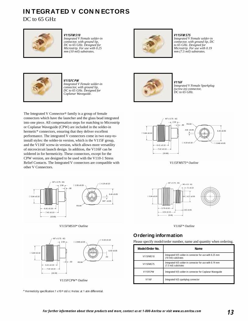
The Integrated V Connector® family is a group of femaleconnectors which have the launcher and the glass bead integratedinto one piece. All compensation steps for matching to Microstripor Coplanar Waveguide (CPW) are included in the solder-inhermetic* connectors, ensuring that they deliver excellentperformance. The integrated V connectors come in two easy-to-install styles: the solder-in version, which is the V115F group,and the V116F screw-in version, which allows more versatilityof microcircuit launch design. In addition, the V116F can besoldered in for hermeticity. These connectors, except for theCPW version, are designed to be used with the V110-1 StressRelief Contacts. The Integrated V connectors are compatible withother V Connectors.
6.41 ±0.10
7.42 ±0.10
.80
2.50
M7 x 0.75 - 6G
R3.94
(10.66)
∅ 4.19 ±0.10
∅ 5.84 ±0.106.40 ±0.05.418 ±0.05
∅ 2.948 ±0.05
V115FMS75Integrated V Female solder-inconnector, with ground lip, DCto 65 GHz. Designed forMicrostrip. For use with 0.19mm (7.5 mil) substrates.
V115FMS75* Outline
6.41 ±0.10
7.42 ±0.10
.50
.02
2.50
M7 x 0.75 - 6G
R3.94
(10.33)
∅ 4.19 ±0.10
6.40 ±0.05
∅ 2.948 ±0.05
∅ 5.84 ±0.10
V115FCPWIntegrated V Female solder-inconnector, with ground lip,DC to 65 GHz. Designed forCoplanar Waveguide.
V115FCPW* Outline
6.41 ±0.10
7.42 ±0.10
.80
2.50
M7 x 0.75 - 6G
R3.94
(10.66)
∅ 4.19 ±0.10∅ 2.95 ±0.05
∅ 5.84 ±0.106.40 ±0.05
.597 ±0.05
V115FMS10Integrated V Female solder-inconnector, with ground lip,DC to 65 GHz. Designed forMicrostrip. For use with 0.25mm (10 mil) substrates.
V115FMS10* Outline
2.92 ±0.055.78 ±0.10
6.54 ±0.10
(9.46)
∅ 4.27 ±0.05∅ 5.84 ±0.10
M7 x 0.75 - 6GM5 x 0.5 - 6G
.71 ±0.10
V116FIntegrated V Female Sparkplug (screw-in) connector,DC to 65 GHz.
V116F* Outline
* Hermeticity specification: 1 x10⁻⁸ std cc He/sec at 1 atm differential.
Ordering informationPlease specify model/order number, name and quantity when ordering.
Model/Order No. Name
V115FMS10 Integrated V(f) solder-in connector for use with 0.25 mm(10 mil) substrates
V115FMS75 Integrated V(f) solder-in connector for use with 0.19 mm(7.5 mil) substrates
V115FCPW Integrated V(f) solder-in connector for Coplanar Waveguide
V116F Integrated V(f) sparkplug connector
For further information about these products and more, contact us at 1-800-Anritsu or visit www.us.anritsu.com14
CONNECTOR TOOLSDC to 65 GHz
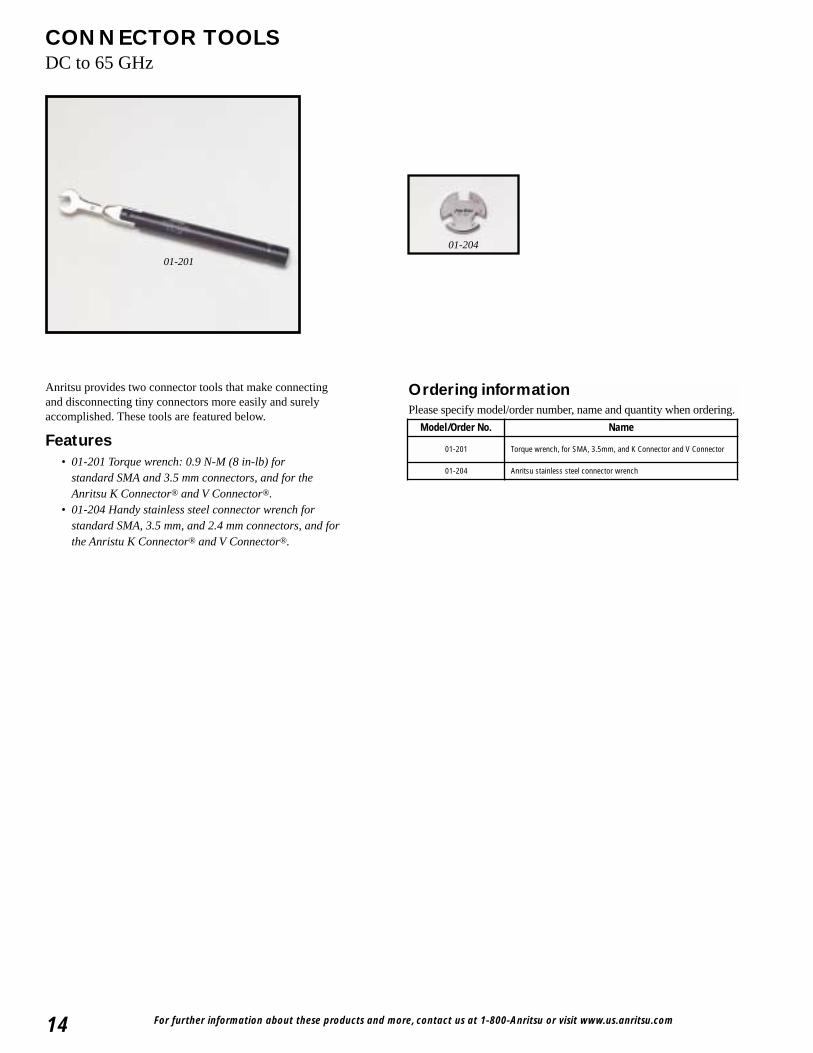
Anritsu provides two connector tools that make connectingand disconnecting tiny connectors more easily and surelyaccomplished. These tools are featured below.
Features• 01-201 Torque wrench: 0.9 N-M (8 in-lb) for
standard SMA and 3.5 mm connectors, and for theAnritsu K Connector® and V Connector®.
• 01-204 Handy stainless steel connector wrench forstandard SMA, 3.5 mm, and 2.4 mm connectors, and forthe Anristu K Connector® and V Connector®.
01-201
01-204
Ordering informationPlease specify model/order number, name and quantity when ordering.
Model/Order No. Name
01-201 Torque wrench, for SMA, 3.5mm, and K Connector and V Connector
01-204 Anritsu stainless steel connector wrench
For further information about these products and more, contact us at 1-800-ANRITSU or visit www.us.anritsu.com 15
VP™ CONNECTORDC to 65 GHz
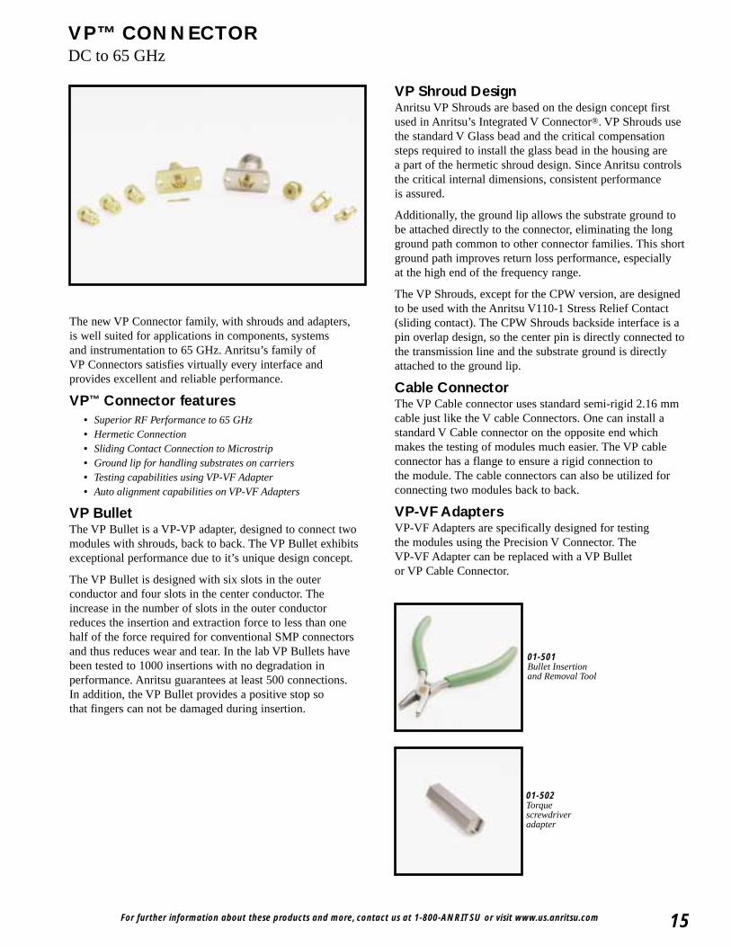
The new VP Connector family, with shrouds and adapters,is well suited for applications in components, systemsand instrumentation to 65 GHz. Anritsu’s family ofVP Connectors satisfies virtually every interface andprovides excellent and reliable performance.
VP™ Connector features• Superior RF Performance to 65 GHz • Hermetic Connection• Sliding Contact Connection to Microstrip• Ground lip for handling substrates on carriers• Testing capabilities using VP-VF Adapter• Auto alignment capabilities on VP-VF Adapters
VP BulletThe VP Bullet is a VP-VP adapter, designed to connect twomodules with shrouds, back to back. The VP Bullet exhibitsexceptional performance due to it’s unique design concept.
The VP Bullet is designed with six slots in the outerconductor and four slots in the center conductor. Theincrease in the number of slots in the outer conductorreduces the insertion and extraction force to less than onehalf of the force required for conventional SMP connectorsand thus reduces wear and tear. In the lab VP Bullets havebeen tested to 1000 insertions with no degradation inperformance. Anritsu guarantees at least 500 connections.In addition, the VP Bullet provides a positive stop sothat fingers can not be damaged during insertion.
VP Shroud DesignAnritsu VP Shrouds are based on the design concept firstused in Anritsu’s Integrated V Connector®. VP Shrouds usethe standard V Glass bead and the critical compensationsteps required to install the glass bead in the housing area part of the hermetic shroud design. Since Anritsu controlsthe critical internal dimensions, consistent performanceis assured.
Additionally, the ground lip allows the substrate ground tobe attached directly to the connector, eliminating the longground path common to other connector families. This shortground path improves return loss performance, especiallyat the high end of the frequency range.
The VP Shrouds, except for the CPW version, are designedto be used with the Anritsu V110-1 Stress Relief Contact(sliding contact). The CPW Shrouds backside interface is apin overlap design, so the center pin is directly connected tothe transmission line and the substrate ground is directlyattached to the ground lip.
Cable ConnectorThe VP Cable connector uses standard semi-rigid 2.16 mmcable just like the V cable Connectors. One can install astandard V Cable connector on the opposite end whichmakes the testing of modules much easier. The VP cableconnector has a flange to ensure a rigid connection tothe module. The cable connectors can also be utilized forconnecting two modules back to back.
VP-VF AdaptersVP-VF Adapters are specifically designed for testingthe modules using the Precision V Connector. The VP-VF Adapter can be replaced with a VP Bulletor VP Cable Connector.
01-501Bullet Insertion and Removal Tool
01-502Torque screwdriver adapter
For further information about these products and more, contact us at 1-800-ANRITSU or visit www.us.anritsu.com16
VP™ CONNECTORDC to 65 GHz
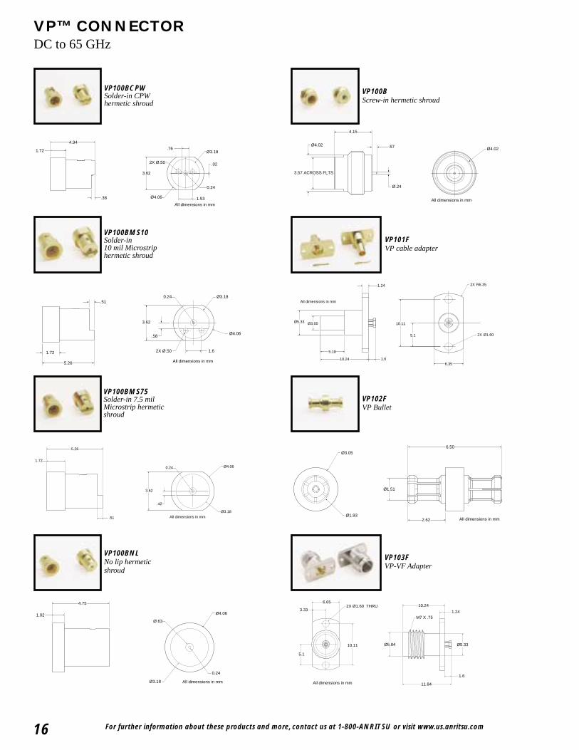
VP100BCPWSolder-in CPW hermetic shroud
Ø4.06
3.62
4.94
1.72 Ø3.18.76
.02
0.24
2X Ø.50
1.53All dimensions in mm
.38
VP100BScrew-in hermetic shroud
4.15
.57
3.57 ACROSS FLTS
Ø4.02Ø4.02
Ø.24
All dimensions in mm
VP100BMS10Solder-in 10 mil Microstrip hermetic shroud
3.62
Ø4.06
Ø3.18
1.72
5.26
2X Ø.50 1.6
.58
.510.24
All dimensions in mm
VP101FVP cable adapter
1.24
10.11
2X R6.35
5.1 2X Ø1.60
Ø3.00Ø5.33
5.18
10.24 1.66.35
All dimensions in mm
VP100BMS75Solder-in 7.5 milMicrostrip hermeticshroud
3.62
Ø4.06
.42
Ø3.18
1.72
5.26
.51
0.24
All dimensions in mm
VP102FVP Bullet
2.62
6.50Ø3.05
Ø1.93
Ø1.51
All dimensions in mm
VP100BNLNo lip hermetic shroud
4.75
1.02 Ø4.06
Ø3.18
Ø.63
0.24
All dimensions in mm
VP103FVP-VF Adapter
5.1
10.24
1.24
11.84
1.6
6.65
10.11
3.332X Ø1.60 THRU
Ø5.84 Ø5.33
M7 X .75
All dimensions in mm
For further information about these products and more, contact us at 1-800-ANRITSU or visit www.us.anritsu.com 17
VP™ CONNECTORDC to 65 GHz
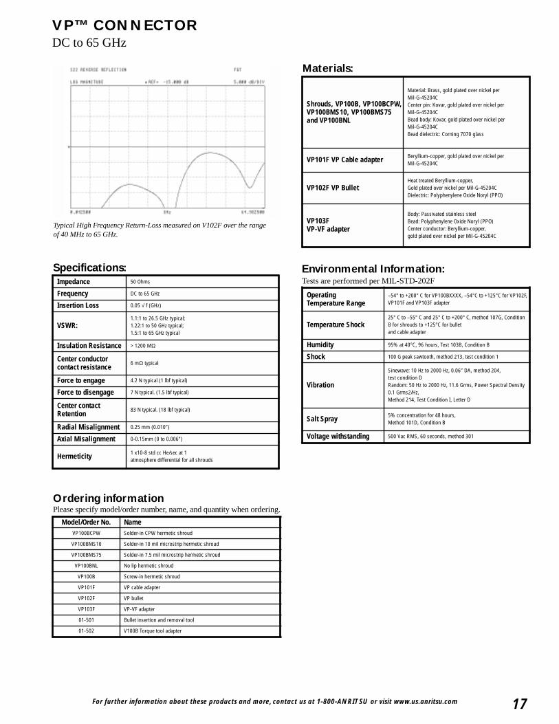
Typical High Frequency Return-Loss measured on V102F over the range of 40 MHz to 65 GHz.
Specifications:Impedance 50 Ohms
Frequency DC to 65 GHz
Insertion Loss 0.05 √ f (GHz)
VSWR:1.1:1 to 26.5 GHz typical;1.22:1 to 50 GHz typical;1.5:1 to 65 GHz typical
Insulation Resistance > 1200 MΩ
Center conductor contact resistance
6 mΩ typical
Force to engage 4.2 N typical (1 lbf typical)
Force to disengage 7 N typical. (1.5 lbf typical)
Center contactRetention
83 N typical. (18 lbf typical)
Radial Misalignment 0.25 mm (0.010”)
Axial Misalignment 0-0.15mm (0 to 0.006”)
Hermeticity 1 x10⁻⁸ std cc He/sec at 1 atmosphere differential for all shrouds
Materials:
Shrouds, VP100B, VP100BCPW,VP100BMS10, VP100BMS75and VP100BNL
Material: Brass, gold plated over nickel per Mil-G-45204CCenter pin: Kovar, gold plated over nickel per Mil-G-45204C Bead body: Kovar, gold plated over nickel per Mil-G-45204CBead dielectric: Corning 7070 glass
VP101F VP Cable adapter Beryllium-copper, gold plated over nickel per Mil-G-45204C
VP102F VP BulletHeat treated Beryllium-copper, Gold plated over nickel per Mil-G-45204C Dielectric: Polyphenylene Oxide Noryl (PPO)
VP103F VP-VF adapter
Body: Passivated stainless steelBead: Polyphenylene Oxide Noryl (PPO)Center conductor: Beryllium-copper, gold plated over nickel per Mil-G-45204C
Operating Temperature Range
–54° to +200° C for VP100BXXXX, –54°C to +125°C for VP102F,VP101F and VP103F adapter
Temperature Shock25° C to –55° C and 25° C to +200° C, method 107G, ConditionB for shrouds to +125°C for bullet and cable adapter
Humidity 95% at 40°C, 96 hours, Test 103B, Condition B
Shock 100 G peak sawtooth, method 213, test condition 1
Vibration
Sinewave: 10 Hz to 2000 Hz, 0.06” DA, method 204, test condition DRandom: 50 Hz to 2000 Hz, 11.6 Grms, Power Spectral Density0.1 Grms2/Hz, Method 214, Test Condition I, Letter D
Salt Spray 5% concentration for 48 hours, Method 101D, Condition B
Voltage withstanding 500 Vac RMS, 60 seconds, method 301
Environmental Information:Tests are performed per MIL-STD-202F
Model/Order No. NameVP100BCPW Solder-in CPW hermetic shroud
VP100BMS10 Solder-in 10 mil microstrip hermetic shroud
VP100BMS75 Solder-in 7.5 mil microstrip hermetic shroud
VP100BNL No lip hermetic shroud
VP100B Screw-in hermetic shroud
VP101F VP cable adapter
VP102F VP bullet
VP103F VP-VF adapter
01-501 Bullet insertion and removal tool
01-502 V100B Torque tool adapter
Ordering informationPlease specify model/order number, name, and quantity when ordering.
For further information about these products and more, contact us at 1-800-Anritsu or visit www.us.anritsu.com18
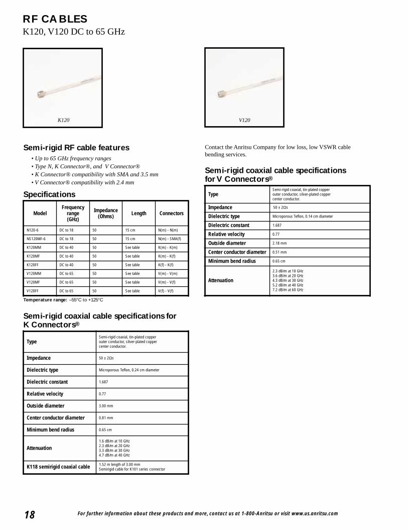
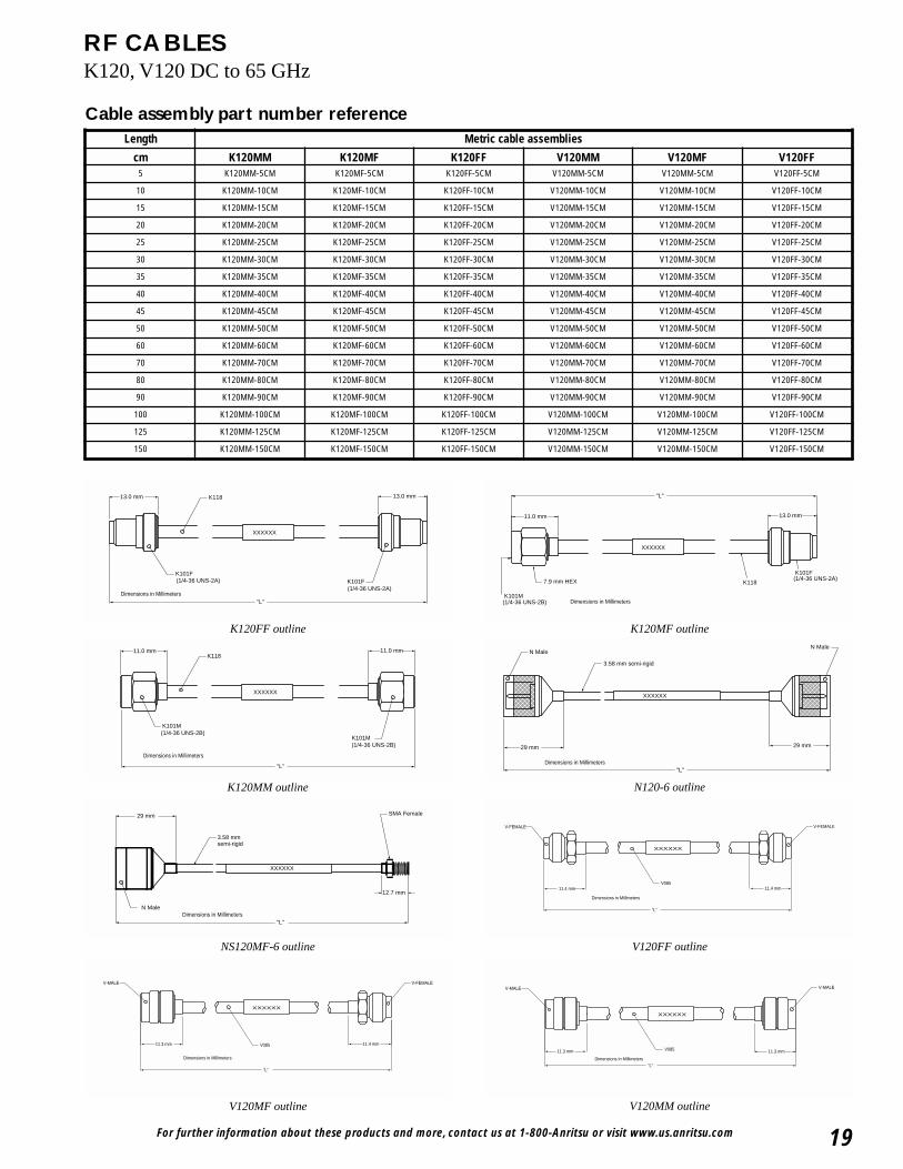
RF CABLESK120, V120 DC to 65 GHz
Semi-rigid RF cable features• Up to 65 GHz frequency ranges• Type N, K Connector®, and V Connector®• K Connector® compatibility with SMA and 3.5 mm• V Connector® compatibility with 2.4 mm
Specifications
K120 V120
Semi-rigid coaxial cable specifications forK Connectors®
Contact the Anritsu Company for low loss, low VSWR cablebending services.
Semi-rigid coaxial cable specificationsforV Connectors®
Temperature range: –55°C to +125°C
ModelFrequency
range (GHz)
Impedance (Ohms) Length Connectors
N120-6 DC to 18 50 15 cm N(m) - N(m)
NS120MF-6 DC to 18 50 15 cm N(m) - SMA(f)
K120MM DC to 40 50 See table K(m) - K(m)
K120MF DC to 40 50 See table K(m) - K(f)
K120FF DC to 40 50 See table K(f) - K(f)
V120MM DC to 65 50 See table V(m) - V(m)
V120MF DC to 65 50 See table V(m) - V(f)
V120FF DC to 65 50 See table V(f) - V(f)
TypeSemi-rigid coaxial, tin-plated copper outer conductor, silver-plated copper center conductor.
Impedance 50 ± 2Ωs
Dielectric type Microporous Teflon, 0.24 cm diameter
Dielectric constant 1.687
Relative velocity 0.77
Outside diameter 3.00 mm
Center conductor diameter 0.81 mm
Minimum bend radius 0.65 cm
Attenuation1.6 dB/m at 10 GHz2.3 dB/m at 20 GHz3.3 dB/m at 30 GHz4.7 dB/m at 40 GHz
K118 semirigid coaxial cable 1.52 m length of 3.00 mmSemirigid cable for K101 series connector
TypeSemi-rigid coaxial, tin-plated copper outer conductor, silver-plated copper center conductor.
Impedance 50 ± 2Ωs
Dielectric type Microporous Teflon, 0.14 cm diameter
Dielectric constant 1.687
Relative velocity 0.77
Outside diameter 2.18 mm
Center conductor diameter 0.51 mm
Minimum bend radius 0.65 cm
Attenuation
2.3 dB/m at 10 GHz3.6 dB/m at 20 GHz4.3 dB/m at 30 GHz5.2 dB/m at 40 GHz7.2 dB/m at 60 GHz
For further information about these products and more, contact us at 1-800-Anritsu or visit www.us.anritsu.com 19
RF CABLESK120, V120 DC to 65 GHz
Cable assembly part number reference
13.0 mm13.0 mm
(1/4-36 UNS-2A)(1/4-36 UNS-2A)
XXXXXX
"L"
K101F
K118
K101F
Dimensions in Millimeters
K120FF outline
V120FF outline
V120MM outlineV120MF outline
11.0 mm 13.0 mm
"L"
XXXXXX
K118
K101F(1/4-36 UNS-2A)
K101M(1/4-36 UNS-2B)
7.9 mm HEX
Dimensions in Millimeters
11.4 mm11.4 mmV085
XXXXXX
V-FEMALE V-FEMALE
"L"
Dimensions in Millimeters
V-FEMALEV-MALE
"L"
V085 11.4 mm11.3 mm
XXXXXX
Dimensions in Millimeters
V-MALEV-MALE
"L"
XXXXXX
V08511.3 mm 11.3 mm
Dimensions in Millimeters
K120MF outline
(1/4-36 UNS-2B)
(1/4-36 UNS-2B)
XXXXXX
"L"
11.0 mm11.0 mm
K101M
K101M
K118
Dimensions in Millimeters
K120MM outline
"L"
12.7 mm
XXXXXX
29 mm
semi-rigid
SMA Female
3.58 mm
N MaleDimensions in Millimeters
NS120MF-6 outline
XXXXXX
29 mm29 mm
"L"
3.58 mm semi-rigid
N MaleN Male
Dimensions in Millimeters
N120-6 outline
Length Metric cable assemblies
cm K120MM K120MF K120FF V120MM V120MF V120FF5 K120MM-5CM K120MF-5CM K120FF-5CM V120MM-5CM V120MM-5CM V120FF-5CM
10 K120MM-10CM K120MF-10CM K120FF-10CM V120MM-10CM V120MM-10CM V120FF-10CM
15 K120MM-15CM K120MF-15CM K120FF-15CM V120MM-15CM V120MM-15CM V120FF-15CM
20 K120MM-20CM K120MF-20CM K120FF-20CM V120MM-20CM V120MM-20CM V120FF-20CM
25 K120MM-25CM K120MF-25CM K120FF-25CM V120MM-25CM V120MM-25CM V120FF-25CM
30 K120MM-30CM K120MF-30CM K120FF-30CM V120MM-30CM V120MM-30CM V120FF-30CM
35 K120MM-35CM K120MF-35CM K120FF-35CM V120MM-35CM V120MM-35CM V120FF-35CM
40 K120MM-40CM K120MF-40CM K120FF-40CM V120MM-40CM V120MM-40CM V120FF-40CM
45 K120MM-45CM K120MF-45CM K120FF-45CM V120MM-45CM V120MM-45CM V120FF-45CM
50 K120MM-50CM K120MF-50CM K120FF-50CM V120MM-50CM V120MM-50CM V120FF-50CM
60 K120MM-60CM K120MF-60CM K120FF-60CM V120MM-60CM V120MM-60CM V120FF-60CM
70 K120MM-70CM K120MF-70CM K120FF-70CM V120MM-70CM V120MM-70CM V120FF-70CM
80 K120MM-80CM K120MF-80CM K120FF-80CM V120MM-80CM V120MM-80CM V120FF-80CM
90 K120MM-90CM K120MF-90CM K120FF-90CM V120MM-90CM V120MM-90CM V120FF-90CM
100 K120MM-100CM K120MF-100CM K120FF-100CM V120MM-100CM V120MM-100CM V120FF-100CM
125 K120MM-125CM K120MF-125CM K120FF-125CM V120MM-125CM V120MM-125CM V120FF-125CM
150 K120MM-150CM K120MF-150CM K120FF-150CM V120MM-150CM V120MM-150CM V120FF-150CM
For further information about these products and more, contact us at 1-800-Anritsu or visit www.us.anritsu.com
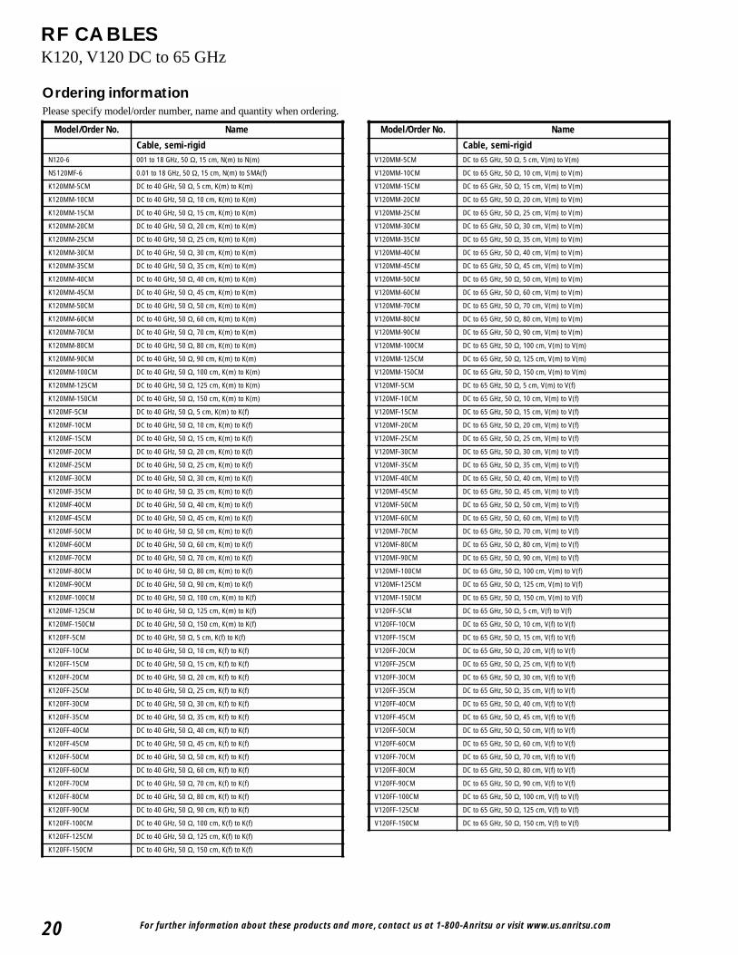
RF CABLESK120, V120 DC to 65 GHz
Ordering informationPlease specify model/order number, name and quantity when ordering.
Model/Order No. Name
Cable, semi-rigidN120-6 001 to 18 GHz, 50 Ω, 15 cm, N(m) to N(m)
NS120MF-6 0.01 to 18 GHz, 50 Ω, 15 cm, N(m) to SMA(f)
K120MM-5CM DC to 40 GHz, 50 Ω, 5 cm, K(m) to K(m)
K120MM-10CM DC to 40 GHz, 50 Ω, 10 cm, K(m) to K(m)
K120MM-15CM DC to 40 GHz, 50 Ω, 15 cm, K(m) to K(m)
K120MM-20CM DC to 40 GHz, 50 Ω, 20 cm, K(m) to K(m)
K120MM-25CM DC to 40 GHz, 50 Ω, 25 cm, K(m) to K(m)
K120MM-30CM DC to 40 GHz, 50 Ω, 30 cm, K(m) to K(m)
K120MM-35CM DC to 40 GHz, 50 Ω, 35 cm, K(m) to K(m)
K120MM-40CM DC to 40 GHz, 50 Ω, 40 cm, K(m) to K(m)
K120MM-45CM DC to 40 GHz, 50 Ω, 45 cm, K(m) to K(m)
K120MM-50CM DC to 40 GHz, 50 Ω, 50 cm, K(m) to K(m)
K120MM-60CM DC to 40 GHz, 50 Ω, 60 cm, K(m) to K(m)
K120MM-70CM DC to 40 GHz, 50 Ω, 70 cm, K(m) to K(m)
K120MM-80CM DC to 40 GHz, 50 Ω, 80 cm, K(m) to K(m)
K120MM-90CM DC to 40 GHz, 50 Ω, 90 cm, K(m) to K(m)
K120MM-100CM DC to 40 GHz, 50 Ω, 100 cm, K(m) to K(m)
K120MM-125CM DC to 40 GHz, 50 Ω, 125 cm, K(m) to K(m)
K120MM-150CM DC to 40 GHz, 50 Ω, 150 cm, K(m) to K(m)
K120MF-5CM DC to 40 GHz, 50 Ω, 5 cm, K(m) to K(f)
K120MF-10CM DC to 40 GHz, 50 Ω, 10 cm, K(m) to K(f)
K120MF-15CM DC to 40 GHz, 50 Ω, 15 cm, K(m) to K(f)
K120MF-20CM DC to 40 GHz, 50 Ω, 20 cm, K(m) to K(f)
K120MF-25CM DC to 40 GHz, 50 Ω, 25 cm, K(m) to K(f)
K120MF-30CM DC to 40 GHz, 50 Ω, 30 cm, K(m) to K(f)
K120MF-35CM DC to 40 GHz, 50 Ω, 35 cm, K(m) to K(f)
K120MF-40CM DC to 40 GHz, 50 Ω, 40 cm, K(m) to K(f)
K120MF-45CM DC to 40 GHz, 50 Ω, 45 cm, K(m) to K(f)
K120MF-50CM DC to 40 GHz, 50 Ω, 50 cm, K(m) to K(f)
K120MF-60CM DC to 40 GHz, 50 Ω, 60 cm, K(m) to K(f)
K120MF-70CM DC to 40 GHz, 50 Ω, 70 cm, K(m) to K(f)
K120MF-80CM DC to 40 GHz, 50 Ω, 80 cm, K(m) to K(f)
K120MF-90CM DC to 40 GHz, 50 Ω, 90 cm, K(m) to K(f)
K120MF-100CM DC to 40 GHz, 50 Ω, 100 cm, K(m) to K(f)
K120MF-125CM DC to 40 GHz, 50 Ω, 125 cm, K(m) to K(f)
K120MF-150CM DC to 40 GHz, 50 Ω, 150 cm, K(m) to K(f)
K120FF-5CM DC to 40 GHz, 50 Ω, 5 cm, K(f) to K(f)
K120FF-10CM DC to 40 GHz, 50 Ω, 10 cm, K(f) to K(f)
K120FF-15CM DC to 40 GHz, 50 Ω, 15 cm, K(f) to K(f)
K120FF-20CM DC to 40 GHz, 50 Ω, 20 cm, K(f) to K(f)
K120FF-25CM DC to 40 GHz, 50 Ω, 25 cm, K(f) to K(f)
K120FF-30CM DC to 40 GHz, 50 Ω, 30 cm, K(f) to K(f)
K120FF-35CM DC to 40 GHz, 50 Ω, 35 cm, K(f) to K(f)
K120FF-40CM DC to 40 GHz, 50 Ω, 40 cm, K(f) to K(f)
K120FF-45CM DC to 40 GHz, 50 Ω, 45 cm, K(f) to K(f)
K120FF-50CM DC to 40 GHz, 50 Ω, 50 cm, K(f) to K(f)
K120FF-60CM DC to 40 GHz, 50 Ω, 60 cm, K(f) to K(f)
K120FF-70CM DC to 40 GHz, 50 Ω, 70 cm, K(f) to K(f)
K120FF-80CM DC to 40 GHz, 50 Ω, 80 cm, K(f) to K(f)
K120FF-90CM DC to 40 GHz, 50 Ω, 90 cm, K(f) to K(f)
K120FF-100CM DC to 40 GHz, 50 Ω, 100 cm, K(f) to K(f)
K120FF-125CM DC to 40 GHz, 50 Ω, 125 cm, K(f) to K(f)
K120FF-150CM DC to 40 GHz, 50 Ω, 150 cm, K(f) to K(f)
Model/Order No. Name
Cable, semi-rigidV120MM-5CM DC to 65 GHz, 50 Ω, 5 cm, V(m) to V(m)
V120MM-10CM DC to 65 GHz, 50 Ω, 10 cm, V(m) to V(m)
V120MM-15CM DC to 65 GHz, 50 Ω, 15 cm, V(m) to V(m)
V120MM-20CM DC to 65 GHz, 50 Ω, 20 cm, V(m) to V(m)
V120MM-25CM DC to 65 GHz, 50 Ω, 25 cm, V(m) to V(m)
V120MM-30CM DC to 65 GHz, 50 Ω, 30 cm, V(m) to V(m)
V120MM-35CM DC to 65 GHz, 50 Ω, 35 cm, V(m) to V(m)
V120MM-40CM DC to 65 GHz, 50 Ω, 40 cm, V(m) to V(m)
V120MM-45CM DC to 65 GHz, 50 Ω, 45 cm, V(m) to V(m)
V120MM-50CM DC to 65 GHz, 50 Ω, 50 cm, V(m) to V(m)
V120MM-60CM DC to 65 GHz, 50 Ω, 60 cm, V(m) to V(m)
V120MM-70CM DC to 65 GHz, 50 Ω, 70 cm, V(m) to V(m)
V120MM-80CM DC to 65 GHz, 50 Ω, 80 cm, V(m) to V(m)
V120MM-90CM DC to 65 GHz, 50 Ω, 90 cm, V(m) to V(m)
V120MM-100CM DC to 65 GHz, 50 Ω, 100 cm, V(m) to V(m)
V120MM-125CM DC to 65 GHz, 50 Ω, 125 cm, V(m) to V(m)
V120MM-150CM DC to 65 GHz, 50 Ω, 150 cm, V(m) to V(m)
V120MF-5CM DC to 65 GHz, 50 Ω, 5 cm, V(m) to V(f)
V120MF-10CM DC to 65 GHz, 50 Ω, 10 cm, V(m) to V(f)
V120MF-15CM DC to 65 GHz, 50 Ω, 15 cm, V(m) to V(f)
V120MF-20CM DC to 65 GHz, 50 Ω, 20 cm, V(m) to V(f)
V120MF-25CM DC to 65 GHz, 50 Ω, 25 cm, V(m) to V(f)
V120MF-30CM DC to 65 GHz, 50 Ω, 30 cm, V(m) to V(f)
V120MF-35CM DC to 65 GHz, 50 Ω, 35 cm, V(m) to V(f)
V120MF-40CM DC to 65 GHz, 50 Ω, 40 cm, V(m) to V(f)
V120MF-45CM DC to 65 GHz, 50 Ω, 45 cm, V(m) to V(f)
V120MF-50CM DC to 65 GHz, 50 Ω, 50 cm, V(m) to V(f)
V120MF-60CM DC to 65 GHz, 50 Ω, 60 cm, V(m) to V(f)
V120MF-70CM DC to 65 GHz, 50 Ω, 70 cm, V(m) to V(f)
V120MF-80CM DC to 65 GHz, 50 Ω, 80 cm, V(m) to V(f)
V120MF-90CM DC to 65 GHz, 50 Ω, 90 cm, V(m) to V(f)
V120MF-100CM DC to 65 GHz, 50 Ω, 100 cm, V(m) to V(f)
V120MF-125CM DC to 65 GHz, 50 Ω, 125 cm, V(m) to V(f)
V120MF-150CM DC to 65 GHz, 50 Ω, 150 cm, V(m) to V(f)
V120FF-5CM DC to 65 GHz, 50 Ω, 5 cm, V(f) to V(f)
V120FF-10CM DC to 65 GHz, 50 Ω, 10 cm, V(f) to V(f)
V120FF-15CM DC to 65 GHz, 50 Ω, 15 cm, V(f) to V(f)
V120FF-20CM DC to 65 GHz, 50 Ω, 20 cm, V(f) to V(f)
V120FF-25CM DC to 65 GHz, 50 Ω, 25 cm, V(f) to V(f)
V120FF-30CM DC to 65 GHz, 50 Ω, 30 cm, V(f) to V(f)
V120FF-35CM DC to 65 GHz, 50 Ω, 35 cm, V(f) to V(f)
V120FF-40CM DC to 65 GHz, 50 Ω, 40 cm, V(f) to V(f)
V120FF-45CM DC to 65 GHz, 50 Ω, 45 cm, V(f) to V(f)
V120FF-50CM DC to 65 GHz, 50 Ω, 50 cm, V(f) to V(f)
V120FF-60CM DC to 65 GHz, 50 Ω, 60 cm, V(f) to V(f)
V120FF-70CM DC to 65 GHz, 50 Ω, 70 cm, V(f) to V(f)
V120FF-80CM DC to 65 GHz, 50 Ω, 80 cm, V(f) to V(f)
V120FF-90CM DC to 65 GHz, 50 Ω, 90 cm, V(f) to V(f)
V120FF-100CM DC to 65 GHz, 50 Ω, 100 cm, V(f) to V(f)
V120FF-125CM DC to 65 GHz, 50 Ω, 125 cm, V(f) to V(f)
V120FF-150CM DC to 65 GHz, 50 Ω, 150 cm, V(f) to V(f)
20
For further information about these products and more, contact us at 1-800-Anritsu or visit www.us.anritsu.com 21
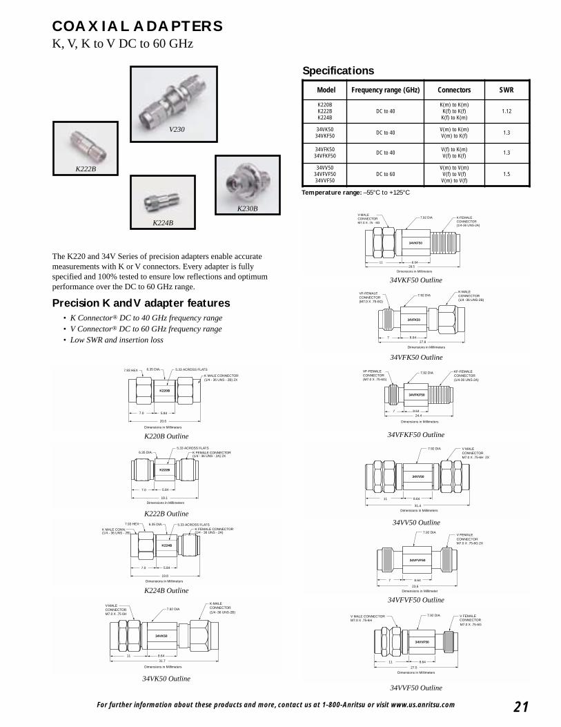
COAXIAL ADAPTERSK, V, K to V DC to 60 GHz
K230B
V230
K222B
K224B
The K220 and 34V Series of precision adapters enable accuratemeasurements with K or V connectors. Every adapter is fullyspecified and 100% tested to ensure low reflections and optimumperformance over the DC to 60 GHz range.
Precision K and V adapter features• K Connector® DC to 40 GHz frequency range• V Connector® DC to 60 GHz frequency range• Low SWR and insertion loss
K220B
7.93 HEX 6.35 DIA. 5.33 ACROSS FLATS
K MALE CONNECTOR(1/4 - 36 UNS - 2B) 2X
7.0 5.84
20.6
Dimensions in Millimeters
K220B Outline
Specifications
K222B
6.35 DIA.5.33 ACROSS FLATS
K FEMALE CONNECTOR(1/4 - 36 UNS - 2A) 2X
7.0 5.84
19.1
Dimensions in Millimeters
K222B Outline
K224B
7.93 HEX 6.35 DIA. 5.33 ACROSS FLATSK FEMALE CONNECTOR(1/4 - 36 UNS - 2A)
7.0 5.84
19.8
Dimensions in Millimeters
K MALE CONN.(1/4 - 36 UNS - 2B)
K224B Outline
31.7
8.6411
34VK50
Dimensions in Millimeters
7.92 DIAV-MALE CONNECTORM7.0 X .75 6H
K-MALE CONNECTOR(1/4 -36 UNS-2B)
34VK50 Outline
24.4
34VFKF50
8.647
VF-FEMALE CONNECTOR(M7.0 X .75-6G)
7.92 DIA KF-FEMALE CONNECTOR(1/4-36 UNS-2A)
Dimensions in Millimeters
34VFKF50 Outline
34VV50
31.4
11 8.64
Dimensions in Millimeters
V MALE CONNECTORM7.0 X .75-6H 2X
7.92 DIA
34VV50 Outline
34VFVF50
23.6
7 8.64
7.92 DIAV FEMALE CONNECTORM7.0 X .75-6G 2X
Dimensions in Millimeter
34VFVF50 Outline
Dimensions in Millimeters
8.6411
27.5
34VVF50
V MALE CONNECTORM7.0 X .75-6H
V FEMALE CONNECTORM7.0 X .75-6G
7.92 DIA
34VVF50 Outline
8.6411
34VKF50
28.5
Dimensions in Millimeters
7.92 DIA K-FEMALE CONNECTOR(1/4-36 UNS-2A)
V-MALE CONNECTORM7.0 X .75 - 6G
34VKF50 Outline
727.8
8.64
34VFK50
7.92 DIAK-MALE CONNECTOR(1/4 -36 UNS-2B)
VF-FEMALE CONNECTOR(M7.0 X .75-6G)
Dimensions in Millimeters
34VFK50 Outline
Temperature range: –55°C to +125°C
Model Frequency range (GHz) Connectors SWR
K220BK222BK224B
DC to 40K(m) to K(m)K(f) to K(f)K(f) to K(m)
1.12
34VK5034VKF50 DC to 40 V(m) to K(m)
V(m) to K(f) 1.3
34VFK5034VFKF50 DC to 40 V(f) to K(m)
V(f) to K(f) 1.3
34VV5034VFVF5034VVF50
DC to 60V(m) to V(m)V(f) to V(f)V(m) to V(f)
1.5
For further information about these products and more, contact us at 1-800-Anritsu or visit www.us.anritsu.com22
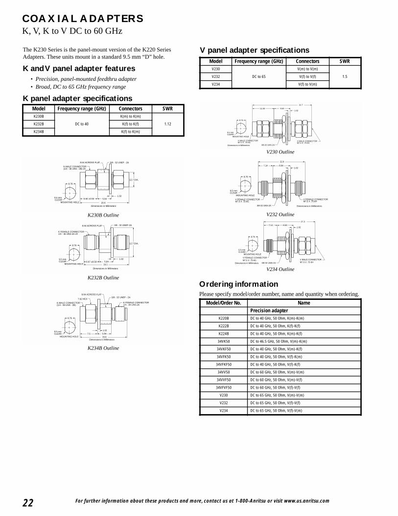
COAXIAL ADAPTERSK, V, K to V DC to 60 GHz
K-MALE CONNECTOR(1/4 - 36 UNS - 2B) 2X
8.64 ACROSS FLAT
6.60 ±0.50 5.84
20.6
Dimensions in Millimeters
3/8 - 32 UNEF - 2A
12.7 DIA.
1.02
8.76
9.5 mm CLEAR
MOUNTING HOLE
K230B Outline
8.64 ACROSS FLAT 3/8 - 32 UNEF-2A
19.1
Dimensions in Millimeters
K FEMALE CONNECTOR1/4 - 36 UNS-2A 2X
6.67 ±0.50 5.841.02
8.76
9.5 mmCLEAR
MOUNTING HOLE
12.7 DIA.
8.76
9.5 mmCLEAR
MOUNTING HOLE 19.6Dimensions in Millimeters
1.02
5.847.5
7.92 HEX
8.64 ACROSS FLAT3/8 - 32 UNEF - 2A
K-MALE CONNECTOR(1/4 - 36 UNS - 2B)
K FEMALE CONNECTOR1/4 - 36 UNS-2A
K232B Outline
K234B Outline
The K230 Series is the panel-mount version of the K220 SeriesAdapters. These units mount in a standard 9.5 mm “D” hole.
K and V panel adapter features• Precision, panel-mounted feedthru adapter• Broad, DC to 65 GHz frequency range
K panel adapter specifications
Ordering informationPlease specify model/order number, name and quantity when ordering.
11.56
31.7
1.028.64
V MALE CONNECTORM7.0 X .75-6G
V MALE CONNECTORM7.0 X .75-6H
3/8-32 UNS-2A
8.76
9.5 mmCLEAR
MOUNTING HOLE
Dimensions in Millimeters
V230 Outline
22.9
7.14 8.641.02
3/8-32 UNS-2A
V FEMALE CONNECTORM7.0 X .75-6H
V FEMALE CONNECTORM7.0 X .75-6G
8.76
9.5 mmCLEAR
MOUNTING HOLE
Dimensions in Millimeters
7.14 8.641.02
27.3
3/8-32 UNS-2A
V FEMALE CONNECTORM7.0 X .75-6G V MALE CONNECTOR
M7.0 X .75-6HDimensions in Millimeters
8.76
9.5 mmCLEAR
MOUNTING HOLE
V232 Outline
V234 Outline
Model Frequency range (GHz) Connectors SWRK230B
DC to 40
K(m) to K(m)
1.12K232B K(f) to K(f)
K234B K(f) to K(m)
Model Frequency range (GHz) Connectors SWRV230
DC to 65
V(m) to V(m)
1.5V232 V(f) to V(f)
V234 V(f) to V(m)
Model/Order No. NamePrecision adapter
K220B DC to 40 GHz, 50 Ohm, K(m)-K(m)
K222B DC to 40 GHz, 50 Ohm, K(f)-K(f)
K224B DC to 40 GHz, 50 Ohm, K(m)-K(f)
34VK50 DC to 46.5 GHz, 50 Ohm, V(m)-K(m)
34VKF50 DC to 40 GHz, 50 Ohm, V(m)-K(f)
34VFK50 DC to 40 GHz, 50 Ohm, V(f)-K(m)
34VFKF50 DC to 40 GHz, 50 Ohm, V(f)-K(f)
34VV50 DC to 60 GHz, 50 Ohm, V(m)-V(m)
34VVF50 DC to 60 GHz, 50 Ohm, V(m)-V(f)
34VFVF50 DC to 60 GHz, 50 Ohm, V(f)-V(f)
V230 DC to 65 GHz, 50 Ohm, V(m)-V(m)
V232 DC to 65 GHz, 50 Ohm, V(f)-V(f)
V234 DC to 65 GHz, 50 Ohm, V(f)-V(m)
V panel adapter specifications
For further information about these products and more, contact us at 1-800-ANRITSU or visit www.us.anritsu.com 23
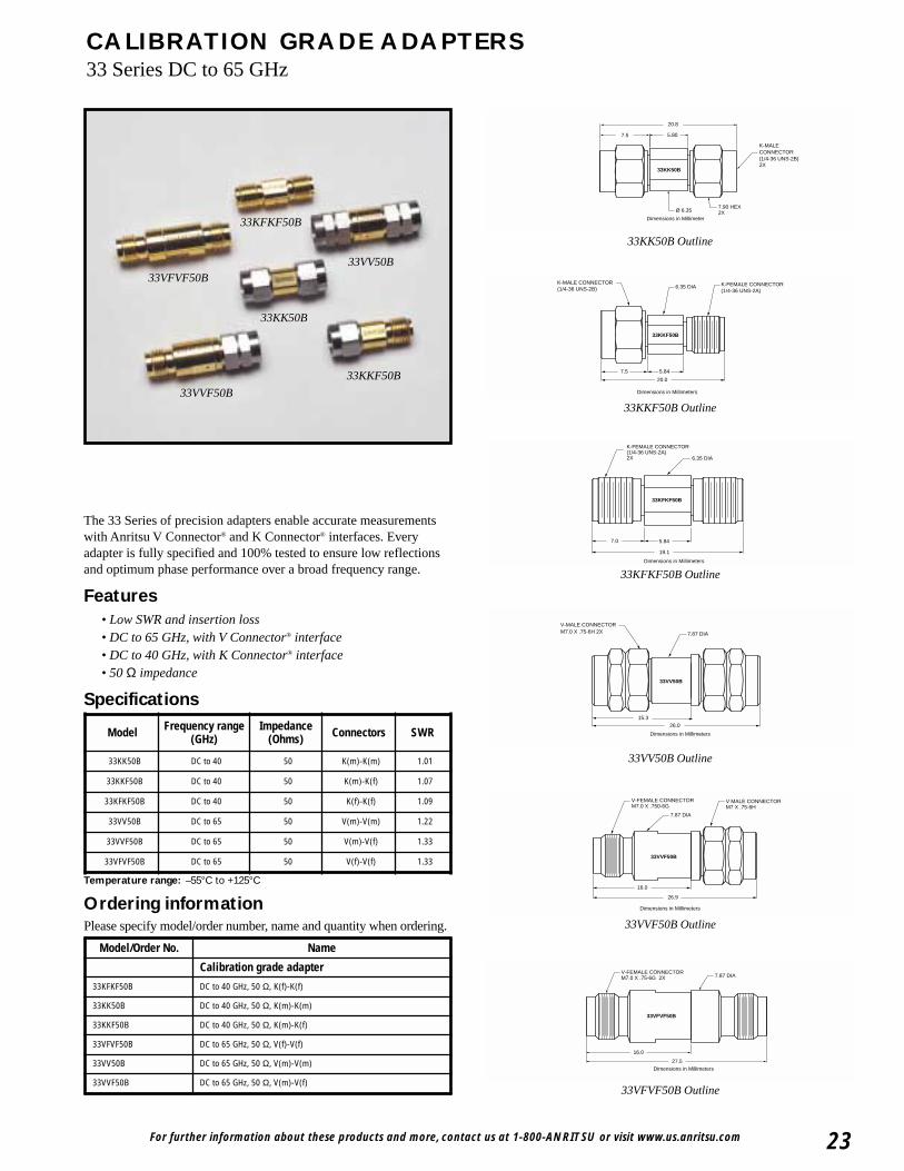
CALIBRATION GRADE ADAPTERS33 Series DC to 65 GHz
The 33 Series of precision adapters enable accurate measurementswith Anritsu V Connector® and K Connector® interfaces. Everyadapter is fully specified and 100% tested to ensure low reflectionsand optimum phase performance over a broad frequency range.
Features• Low SWR and insertion loss• DC to 65 GHz, with V Connector® interface• DC to 40 GHz, with K Connector® interface• 50 Ω impedance
Specifications
Temperature range: –55°C to +125°C
Model Frequency range (GHz)
Impedance(Ohms) Connectors SWR
33KK50B DC to 40 50 K(m)-K(m) 1.01
33KKF50B DC to 40 50 K(m)-K(f) 1.07
33KFKF50B DC to 40 50 K(f)-K(f) 1.09
33VV50B DC to 65 50 V(m)-V(m) 1.22
33VVF50B DC to 65 50 V(m)-V(f) 1.33
33VFVF50B DC to 65 50 V(f)-V(f) 1.33
Ordering informationPlease specify model/order number, name and quantity when ordering.
Model/Order No. Name
Calibration grade adapter
33KFKF50B DC to 40 GHz, 50 Ω, K(f)-K(f)
33KK50B DC to 40 GHz, 50 Ω, K(m)-K(m)
33KKF50B DC to 40 GHz, 50 Ω, K(m)-K(f)
33VFVF50B DC to 65 GHz, 50 Ω, V(f)-V(f)
33VV50B DC to 65 GHz, 50 Ω, V(m)-V(m)
33VVF50B DC to 65 GHz, 50 Ω, V(m)-V(f)
33KFKF50B
7.0 5.84
19.1
Dimensions in Millimeters
6.35 DIA
K-FEMALE CONNECTOR(1/4-36 UNS-2A)2X
33KFKF50B Outline
Dimensions in Millimeters
33VV50B
26.015.3
V-MALE CONNECTORM7.0 X .75-6H 2X 7.87 DIA
33VV50B Outline
33VVF50B
26.9
16.0
Dimensions in Millimeters
V MALE CONNECTORM7 X .75-6H
V-FEMALE CONNECTORM7.0 X .750-6G
7.87 DIA
33VVF50B Outline
27.5
16.0
Dimensions in Millimeters
33VFVF50B
V-FEMALE CONNECTORM7.0 X .75-6G 2X 7.87 DIA
33VFVF50B Outline
33KKF50B
Dimensions in Millimeters
20.0
7.5 5.84
K-FEMALE CONNECTOR(1/4-36 UNS-2A)
K-MALE CONNECTOR(1/4-36 UNS-2B) 6.35 DIA
33KKF50B Outline
5.807.5
20.8
33KK50B
K-MALE CONNECTOR(1/4-36 UNS-2B)2X
Ø 6.357.90 HEX2X
Dimensions in Millimeter
33KK50B Outline
33VV50B
33KK50B
33VFVF50B
33KFKF50B
33KKF50B
33VVF50B
For further information about these products and more, contact us at 1-800-ANRITSU or visit www.us.anritsu.com24
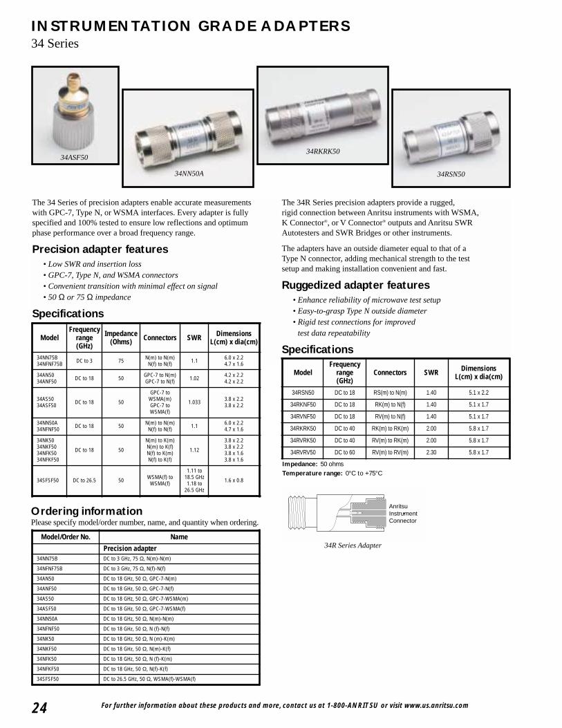
INSTRUMENTATION GRADE ADAPTERS34 Series
The 34 Series of precision adapters enable accurate measurementswith GPC-7, Type N, or WSMA interfaces. Every adapter is fullyspecified and 100% tested to ensure low reflections and optimumphase performance over a broad frequency range.
Precision adapter features• Low SWR and insertion loss• GPC-7, Type N, and WSMA connectors• Convenient transition with minimal effect on signal• 50 Ω or 75 Ω impedance
Specifications
The 34R Series precision adapters provide a rugged,rigid connection between Anritsu instruments with WSMA,K Connector®, or V Connector® outputs and Anritsu SWRAutotesters and SWR Bridges or other instruments.
The adapters have an outside diameter equal to that of aType N connector, adding mechanical strength to the testsetup and making installation convenient and fast.
Ruggedized adapter features• Enhance reliability of microwave test setup• Easy-to-grasp Type N outside diameter• Rigid test connections for improved
test data repeatability
Specifications
34RSN50
34RKRK5034ASF50
34NN50A
ModelFrequency
range(GHz)
Impedance(Ohms) Connectors SWR Dimensions
L(cm) x dia(cm)
34NN75B34NFNF75B DC to 3 75 N(m) to N(m)
N(f) to N(f) 1.1 6.0 x 2.24.7 x 1.6
34AN5034ANF50 DC to 18 50 GPC-7 to N(m)
GPC-7 to N(f) 1.02 4.2 x 2.24.2 x 2.2
34AS5034ASF50 DC to 18 50
GPC-7 toWSMA(m)GPC-7 toWSMA(f)
1.033 3.8 x 2.23.8 x 2.2
34NN50A34NFNF50 DC to 18 50 N(m) to N(m)
N(f) to N(f) 1.1 6.0 x 2.24.7 x 1.6
34NK5034NKF5034NFK5034NFKF50
DC to 18 50
N(m) to K(m)N(m) to K(f)N(f) to K(m)N(f) to K(f)
1.12
3.8 x 2.23.8 x 2.23.8 x 1.63.8 x 1.6
34SFSF50 DC to 26.5 50 WSMA(f) toWSMA(f)
1.11 to18.5 GHz1.18 to
26.5 GHz
1.6 x 0.8
ModelFrequency
range(GHz)
Connectors SWR DimensionsL(cm) x dia(cm)
34RSN50 DC to 18 RS(m) to N(m) 1.40 5.1 x 2.2
34RKNF50 DC to 18 RK(m) to N(f) 1.40 5.1 x 1.7
34RVNF50 DC to 18 RV(m) to N(f) 1.40 5.1 x 1.7
34RKRK50 DC to 40 RK(m) to RK(m) 2.00 5.8 x 1.7
34RVRK50 DC to 40 RV(m) to RK(m) 2.00 5.8 x 1.7
34RVRV50 DC to 60 RV(m) to RV(m) 2.30 5.8 x 1.7
Impedance: 50 ohmsTemperature range: 0°C to +75°C
AnritsuInstrumentConnector
34R Series Adapter
Ordering informationPlease specify model/order number, name, and quantity when ordering.
Model/Order No. Name
Precision adapter34NN75B DC to 3 GHz, 75 Ω, N(m)-N(m)
34NFNF75B DC to 3 GHz, 75 Ω, N(f)-N(f)
34AN50 DC to 18 GHz, 50 Ω, GPC-7-N(m)
34ANF50 DC to 18 GHz, 50 Ω, GPC-7-N(f)
34AS50 DC to 18 GHz, 50 Ω, GPC-7-WSMA(m)
34ASF50 DC to 18 GHz, 50 Ω, GPC-7-WSMA(f)
34NN50A DC to 18 GHz, 50 Ω, N(m)-N(m)
34NFNF50 DC to 18 GHz, 50 Ω, N (f)-N(f)
34NK50 DC to 18 GHz, 50 Ω, N (m)-K(m)
34NKF50 DC to 18 GHz, 50 Ω, N(m)-K(f)
34NFK50 DC to 18 GHz, 50 Ω, N (f)-K(m)
34NFKF50 DC to 18 GHz, 50 Ω, N(f)-K(f)
34SFSF50 DC to 26.5 GHz, 50 Ω, WSMA(f)-WSMA(f)
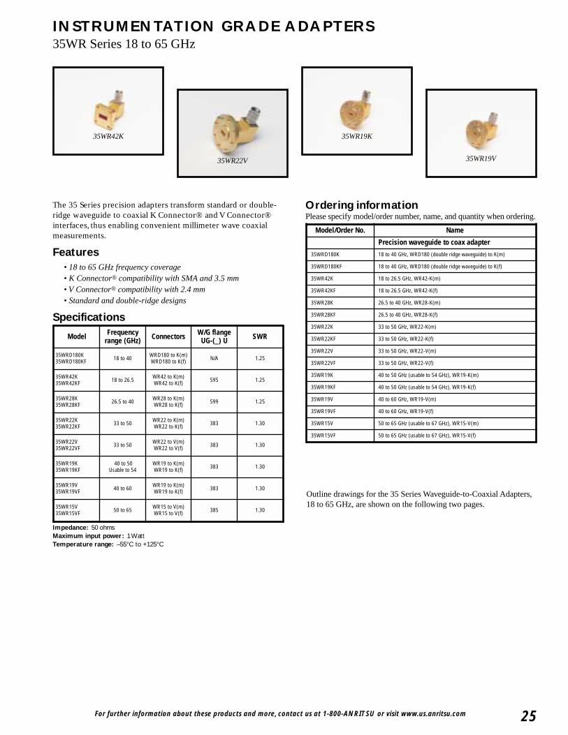
For further information about these products and more, contact us at 1-800-ANRITSU or visit www.us.anritsu.com 25
INSTRUMENTATION GRADE ADAPTERS35WR Series 18 to 65 GHz
35WR42K 35WR19K
35WR22V 35WR19V
The 35 Series precision adapters transform standard or double-ridge waveguide to coaxial K Connector® and V Connector®interfaces, thus enabling convenient millimeter wave coaxialmeasurements.
Features• 18 to 65 GHz frequency coverage• K Connector® compatibility with SMA and 3.5 mm• V Connector® compatibility with 2.4 mm• Standard and double-ridge designs
Specifications
Impedance: 50 ohmsMaximum input power: 1 WattTemperature range: –55°C to +125°C
Ordering informationPlease specify model/order number, name, and quantity when ordering.
Model Frequencyrange (GHz) Connectors W/G flange
UG-(_) U SWR
35WRD180K35WRD180KF 18 to 40 WRD180 to K(m)
WRD180 to K(f) N/A 1.25
35WR42K35WR42KF 18 to 26.5 WR42 to K(m)
WR42 to K(f) 595 1.25
35WR28K35WR28KF 26.5 to 40 WR28 to K(m)
WR28 to K(f) 599 1.25
35WR22K35WR22KF 33 to 50 WR22 to K(m)
WR22 to K(f) 383 1.30
35WR22V35WR22VF 33 to 50 WR22 to V(m)
WR22 to V(f) 383 1.30
35WR19K35WR19KF
40 to 50Usable to 54
WR19 to K(m)WR19 to K(f) 383 1.30
35WR19V35WR19VF 40 to 60 WR19 to K(m)
WR19 to K(f) 383 1.30
35WR15V35WR15VF 50 to 65 WR15 to V(m)
WR15 to V(f) 385 1.30
Model/Order No. Name
Precision waveguide to coax adapter
35WRD180K 18 to 40 GHz, WRD180 (double ridge waveguide) to K(m)
35WRD180KF 18 to 40 GHz, WRD180 (double ridge waveguide) to K(f)
35WR42K 18 to 26.5 GHz, WR42-K(m)
35WR42KF 18 to 26.5 GHz, WR42-K(f)
35WR28K 26.5 to 40 GHz, WR28-K(m)
35WR28KF 26.5 to 40 GHz, WR28-K(f)
35WR22K 33 to 50 GHz, WR22-K(m)
35WR22KF 33 to 50 GHz, WR22-K(f)
35WR22V 33 to 50 GHz, WR22-V(m)
35WR22VF 33 to 50 GHz, WR22-V(f)
35WR19K 40 to 50 GHz (usable to 54 GHz), WR19-K(m)
35WR19KF 40 to 50 GHz (usable to 54 GHz), WR19-K(f)
35WR19V 40 to 60 GHz, WR19-V(m)
35WR19VF 40 to 60 GHz, WR19-V(f)
35WR15V 50 to 65 GHz (usable to 67 GHz), WR15-V(m)
35WR15VF 50 to 65 GHz (usable to 67 GHz), WR15-V(f)
Outline drawings for the 35 Series Waveguide-to-Coaxial Adapters,18 to 65 GHz, are shown on the following two pages.
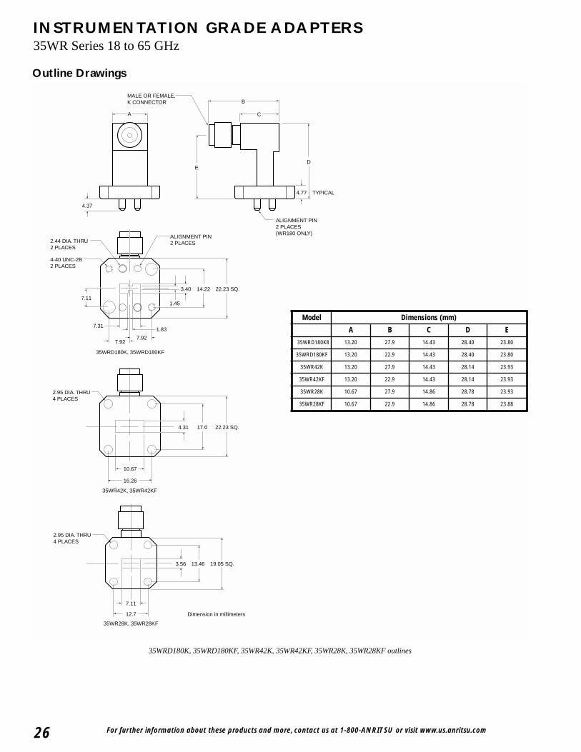
For further information about these products and more, contact us at 1-800-ANRITSU or visit www.us.anritsu.com26
INSTRUMENTATION GRADE ADAPTERS35WR Series 18 to 65 GHz
Outline Drawings
B
CA
ED
ALIGNMENT PIN2 PLACES(WR180 ONLY)
MALE OR FEMALE, K CONNECTOR
4.37
4.77 TYPICAL
2.95 DIA. THRU4 PLACES
35WR42K, 35WR42KF
4.31 17.0 22.23 SQ.
16.26
10.67
ALIGNMENT PIN2 PLACES2.44 DIA. THRU
2 PLACES
35WRD180K, 35WRD180KF
7.927.92
7.311.83
1.45
3.40 14.22 22.23 SQ.
7.11
4-40 UNC-2B2 PLACES
35WR28K, 35WR28KF
2.95 DIA. THRU4 PLACES
19.05 SQ.13.463.56
7.11
12.7 Dimension in millimeters
35WRD180K, 35WRD180KF, 35WR42K, 35WR42KF, 35WR28K, 35WR28KF outlines
Model Dimensions (mm)
A B C D E
35WRD180K8 13.20 27.9 14.43 28.40 23.80
35WRD180KF 13.20 22.9 14.43 28.40 23.80
35WR42K 13.20 27.9 14.43 28.14 23.93
35WR42KF 13.20 22.9 14.43 28.14 23.93
35WR28K 10.67 27.9 14.86 28.78 23.93
35WR28KF 10.67 22.9 14.86 28.78 23.88
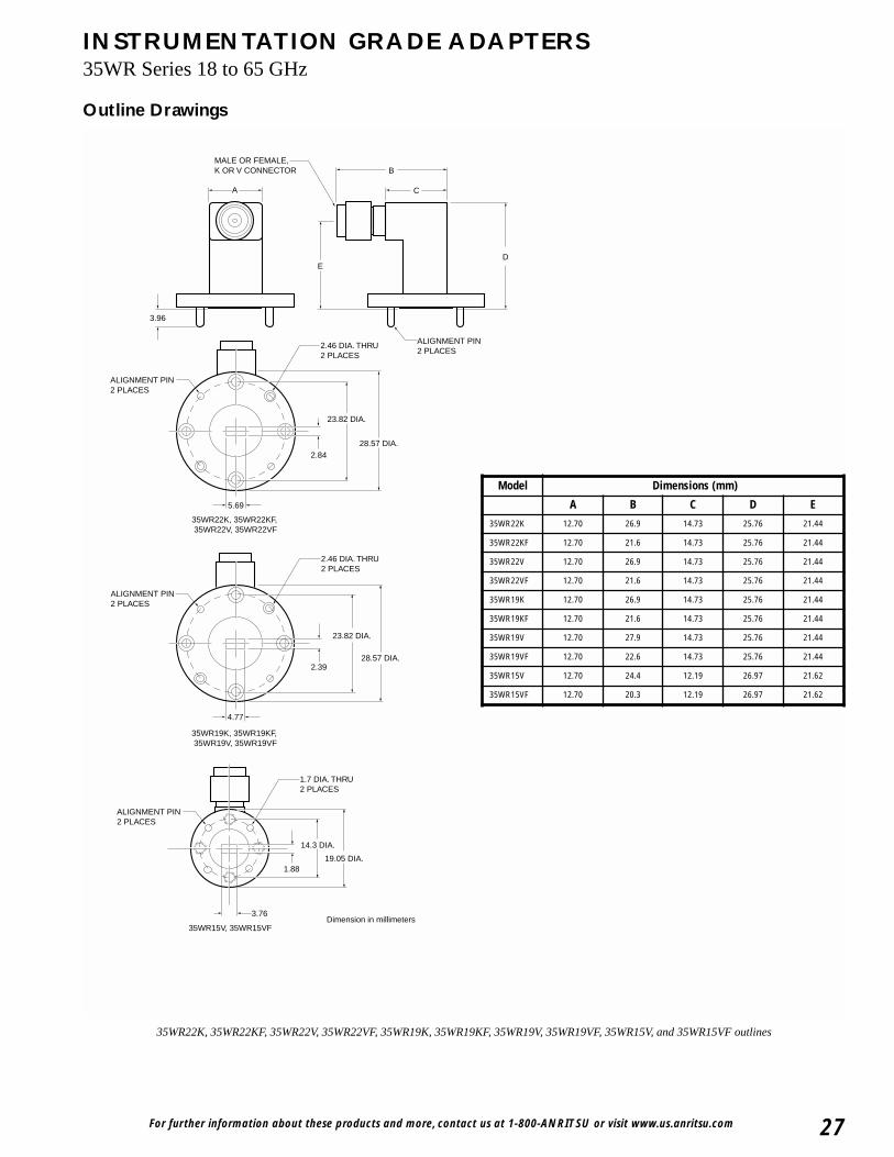
For further information about these products and more, contact us at 1-800-ANRITSU or visit www.us.anritsu.com 27
INSTRUMENTATION GRADE ADAPTERS35WR Series 18 to 65 GHz
Outline Drawings
ALIGNMENT PIN2 PLACES
2.46 DIA. THRU2 PLACES
35WR22K, 35WR22KF, 35WR22V, 35WR22VF
28.57 DIA.2.84
23.82 DIA.
5.69
2.46 DIA. THRU2 PLACES
ALIGNMENT PIN2 PLACES
35WR19K, 35WR19KF, 35WR19V, 35WR19VF
28.57 DIA.
23.82 DIA.
2.39
4.77
ED
B
CA
MALE OR FEMALE, K OR V CONNECTOR
ALIGNMENT PIN2 PLACES
3.96
ALIGNMENT PIN2 PLACES
1.7 DIA. THRU2 PLACES
35WR15V, 35WR15VF
19.05 DIA.
14.3 DIA.
1.88
3.76Dimension in millimeters
35WR22K, 35WR22KF, 35WR22V, 35WR22VF, 35WR19K, 35WR19KF, 35WR19V, 35WR19VF, 35WR15V, and 35WR15VF outlines
Model Dimensions (mm)
A B C D E
35WR22K 12.70 26.9 14.73 25.76 21.44
35WR22KF 12.70 21.6 14.73 25.76 21.44
35WR22V 12.70 26.9 14.73 25.76 21.44
35WR22VF 12.70 21.6 14.73 25.76 21.44
35WR19K 12.70 26.9 14.73 25.76 21.44
35WR19KF 12.70 21.6 14.73 25.76 21.44
35WR19V 12.70 27.9 14.73 25.76 21.44
35WR19VF 12.70 22.6 14.73 25.76 21.44
35WR15V 12.70 24.4 12.19 26.97 21.62
35WR15VF 12.70 20.3 12.19 26.97 21.62

For further information about these products and more, contact us at 1-800-ANRITSU or visit www.us.anritsu.com28
INSTRUMENTATION GRADE ADAPTERS 35U, 35C Series 3.3 to 26.5 GHz
35UM40N
35UM84N
35UA187N
The 35U and 35C Series precision adapters transform standardwaveguide to coaxial N and K Connector® interfaces, thus enablingconvenient microwave coaxial measurements.
Features• 3.3 to 26.5 GHz frequency coverage• N connector compatibility• K Connector® compatibility with SMA and 3.5 mm
Specifications
35UA42K
Model Frequencyrange (GHz) Connectors W/G flange UG-(_) U SWR
35UM40N 3.3 to 4.9 WR229 to N(m) WG11A to N(m) PDR40 1.08
35UM48N 3.9 to 5.8 WR187 to N(m) WG12 to N(m)
CAR48, PAR48, UAR48, PDR48 1.08
35UM58N 4.9 to 7.0 WR159 to N(m) WG13 to N(m)
CAR58, PAR58, UAR58, PDR58 1.08
35UM70N 5.8 to 8.2 WR137 to N(m) WG14 to N(m)
CAR70, PAR70, UAR70, PDR70 1.08
35UM84N 7.0 to 10 WR112 to N(m) WG15 to N(m)
CBR84, UBR84, PBR84, PDR84 1.08
35UM100N 8.2 to 12.4 WR90 to N(m) WG16 to N(m)
CBR100, UBR100, PBR100, PDR100 1.08
35UM120N 10 to 15 WR75 to N(m) WG17 to N(m)
CBR120, UBR120, PBR120, PDR120 1.08
35UM140N 12.4 to 18 WR62 to N(m) WG18 to N(m)
CBR140, UBR140, PBR140, PDR140 1.08
35UM220K 17 to 26.5 WR42 to K(m) WG20 to K(m)
CBR220, UBR220, PBR220, PDR220 1.20
35UA229N 3.3 to 4.9 WR229 to N(m) WG11A to N(m)
CPR229F, CPR229G, UG-1350/U, UG-1351/U, UG-1726/U, UG-1727/U
1.08
35UA187N 3.9 to 5.8 WR187 to N(m) WG12 to N(m)
CPR187F, CPR187G, UG-1352/U, UG-1353/U, UG-1728/U, UG-1729/U, UG-148/U, UG-149A/U
1.08
35UA159N 4.9 to 7.0 WR159 to N(m) WG13 to N(m)
CPR159F, CPR159G, UG-1354/U, UG-1355/U, UG-1730/U, UG-1731/U
1.08
35UA137N 5.8 to 8.2 WR137 to N(m) WG14 to N(m)
CPR137F, CPR137G, UG-1356/U, UG-1357/U, UG-1732/U, UG-1733/U, UG-343B/U, UG-344/U, UG-440B/U, UG-441/U
1.08
Model Frequencyrange (GHz) Connectors W/G flange UG-(_) U SWR
35UA112N 7.0 to 10 WR112 to N(m) WG15 to N(m)
CPR112F, CPR112G, UG-1358/U, UG-1359/U, UG-1734/U, UG-1735/U,
UG-52B/U, UG-51/U, UG-137B/U, UG-138/U
1.08
35UA90N 8.2 to 12.4 WR90 to N(m) WG16 to N(m)
CPR90F, CPR90G, UG-1360/U, UG-1361/U, UG-1736/U, UG-1737/U,
UG-40B/U, UG-39/U, UG-135B/U, UG-136/U
1.08
35UA75N 10 to 15 WR75 to N(m) WG17 to N(m) WR75 1.08
35UA62N 12.4 to 18 WR62 to N(m) WG18 to N(m)
UG-541A/U, UG-419A/U UG-1665/U, UG-1666/U 1.08
35UA42K 17 to 26.5 WR42 to K(m) WG20 to K(m)
UG-596A/U, UG-595/U, UG-597/U, UG-598A/U 1.08
35CMR229N 3.3 to 4.9 WR229 to N(m) CMR229 1.08
35CMR187N 3.9 to 5.8 WR187 to N(m) WG12 to N(m)
CMR187, UG-1475/U, UG-148/U 1.08
35CMR159N 4.9 to 7.0 WR159 to N(m)WG13 to N(m) CMR159 1.08
35CMR137N 5.8 to 8.2 WR137 to N(m)WG14 to N(m)
CMR137, UG-1476/U 1UG-1481/U 1.08
35CMR112N 7.0 to 10 WR112 to N(m)WG15 to N(m)
CMR112, UG-1477/U UG-1482/U 1.08
35CMR90N 8.2 to 12.4 WR90 to N(m)WG16 to N(m)
CMR90, UG-1478/U UG-1483/U 1.08
35UER40N 3.3 to 4.9 WR229 to N(m)WG11A to N(m) UER40 1.08
35UER48N 3.9 to 5.8 WR187 to N(m)WG12 to N(m) UER48 1.08
35UER58N 4.9 to 7.0 WR159 to N(m)WG13 to N(m) UER58 1.08
35UER70N 5.8 to 8.2 WR137 to N(m)WG14 to N(m) UER70 1.08
35UER84N 7 to 10 WR112 to N(m)WG15 to N(m) UER84 1.08
35UER100N 8.2 to 12.4 WR90 to N(m)WG16 to N(m) UER100 1.08
Specifications
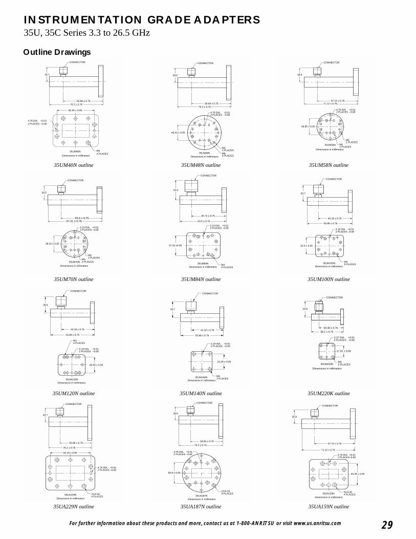
For further information about these products and more, contact us at 1-800-ANRITSU or visit www.us.anritsu.com 29
INSTRUMENTATION GRADE ADAPTERS35U, 35C Series 3.3 to 26.5 GHz
M64 PLACES
35UM40N
82.30 ± 0.05
4.76 DIA.2 PLACES
+0.01–0.00
Dimensions in millimeters
CONNECTOR
43.7
55.88 ± 0.7676.2 ± 0.76
35UM40N outline
M52 PLACES
M54 PLACES
36.52 ± 0.05
35UM70N
CONNECTOR
34.5
50.8 ± 0.76 67.31 ± 0.76
Dimensions in millimeters
3.19 DIA. +0.012 PLACES –0.00
35UM70N outline
M44 PLACES
28.50 ± 0.05
35UM120N
CONNECTOR
30.5
43.18 ± 0.76
55.88 ± 0.76
3.19 DIA.2 PLACES
+0.01–0.00
Dimensions in millimeters
35UM120N outline
35UA229N
82.29 ± 0.05
#1/4-204 PLACES
43.7
55.88 ± 0.76
76.2 ± 0.76
Dimensions in millimeters
CONNECTOR
4.76 DIA. +0.012 PLACES −0.00
35UA229N outline
M54 PLACESM64 PLACES
46.43 ± 0.05
35UM48N
4.76 DIA.2 PLACES
+0.01–0.00
Dimensions in millimeters
CONNECTOR
39.6
59.69 ± 0.76 76.2 ± 0.76
35UM48N outline
M46 PLACES
37.43 ±0.05
35UM84N
CONNECTOR
32.0
45.72 ± 0.76
63.5 ± 0.76
Dimensions in millimeters
3.19 DIA. +0.012 PLACES –0.00
35UM84N outline
M42 PLACES
24.28 ± 0.05
35UM140N
CONNECTOR
29.7
43.18 ± 0.76
55.88 ± 0.76
3.19 DIA.2 PLACES
+0.01–0.00
Dimensions in millimeters
35UM140N outline
#1/4-208 PLACES
35UA187N
50.8 ± 0.05
Dimensions in millimeters
4.76 DIA.2 PLACES
+0.01–0.00
39.6
59.69 ± 0.76
76.2 ± 0.76
CONNECTOR
35UA187N outline
M52 PLACES
M64 PLACES
69.85 ± 0.05
35UM58N
CONNECTOR
36.8
57.15 ± 0.76 71.12 ± 0.76
4.76 DIA.2 PLACES
+0.01–0.00
Dimensions in millimeters
35UM58N outline
M46 PLACES
32.5 ± 0.05
35UM100N
CONNECTOR
30.7
43.18 ± 0.76
55.88 ± 0.76
Dimensions in millimeters
3.19 DIA. +0.012 PLACES –0.00
35UM100N outline
M32 PLACES
17.01 ± 0.05
35UM220K
CONNECTOR
19.8
30.48 ± 0.76
38.1 ± 0.76
2.37 DIA.2 PLACES
+0.01–0.00
Dimensions in millimeters
35UM220K outline
57.15 ± 0.76
71.12 ± 0.76
44.45 ± 0.05
36.8
Dimensions in millimeters
#1/4-204 PLACES35UA159N
CONNECTOR
4.76 DIA. +0.012 PLACES−0.00
35UA159N outline
Outline Drawings
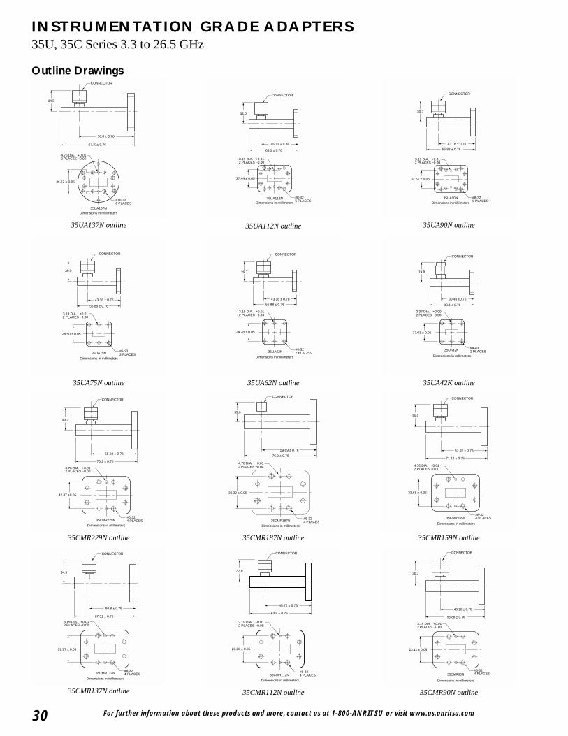
For further information about these products and more, contact us at 1-800-ANRITSU or visit www.us.anritsu.com30
INSTRUMENTATION GRADE ADAPTERS35U, 35C Series 3.3 to 26.5 GHz
CONNECTOR
34.5
50.8 ± 0.76
67.31± 0.76
Dimensions in millimeters
#10-326 PLACES
35UA137N
36.52 ± 0.05
4.76 DIA. +0.012 PLACES −0.00
35UA137N outline
28.50 ± 0.05
#6-322 PLACES35UA75N
43.18 ± 0.76
55.88 ± 0.76
CONNECTOR
30.5
Dimensions in millimeters
3.19 DIA. +0.012 PLACES −0.00
35UA75N outline
#6-324 PLACES
42.87 ±0.05
35CMR229N
43.7
55.88 ± 0.76
76.2 ± 0.76
Dimensions in millimeters
CONNECTOR
4.76 DIA. +0.012 PLACES −0.00
35CMR229N outline
#6-324 PLACES
CONNECTOR
29.97 ± 0.05
35CMR137N
34.5
50.8 ± 0.76
67.31 ± 0.76
Dimensions in millimeters
3.19 DIA. +0.012 PLACES −0.00
35CMR137N outline
CONNECTOR
45.72 ± 0.76
32.0
Dimensions in millimeters
37.44 ± 0.05
#8-326 PLACES
35UA112N
63.5 ± 0.76
3.19 DIA. +0.012 PLACES −0.00
35UA112N outline
CONNECTOR
29.7
43.18 ± 0.76
55.88 ± 0.76
#6-322 PLACES
24.28 ± 0.05
35UA62N
Dimensions in millimeters
3.19 DIA. +0.012 PLACES −0.00
35UA62N outline
#6-324 PLACES
CONNECTOR
36.32 ± 0.05
35CMR187N
39.6
59.69 ± 0.76
76.2 ± 0.76
Dimensions in millimeters
4.76 DIA. +0.012 PLACES −0.00
35CMR187N outline
#6-324 PLACES
CONNECTOR
26.26 ± 0.05
35CMR112N
32.0
45.72 ± 0.76
63.5 ± 0.76
Dimensions in millimeters
3.19 DIA. +0.012 PLACES −0.00
35CMR112N outline
CONNECTOR
43.18 ± 0.76
55.88 ± 0.76
Dimensions in millimeters
#8-326 PLACES
32.51 ± 0.05
35UA90N
30.7
3.19 DIA. +0.012 PLACES −0.00
35UA90N outline
CONNECTOR
19.8
30.48 ±0.76
38.1 ± 0.76
Dimensions in millimeters
#4-402 PLACES
17.01 ± 0.05
35UA42K
2.37 DIA. +0.002 PLACES −0.00
35UA42K outline
#6-324 PLACES
CONNECTOR
33.68 ± 0.05
35CMR159N
36.8
57.15 ± 0.76
71.12 ± 0.76
Dimensions in millimeters
4.76 DIA. +0.012 PLACES −0.00
35CMR159N outline
#6-324 PLACES
CONNECTOR
23.11 ± 0.05
35CMR90N
30.7
43.18 ± 0.76
55.88 ± 0.76
Dimensions in millimeters
3.19 DIA. +0.012 PLACES −0.00
35CMR90N outline
Outline Drawings
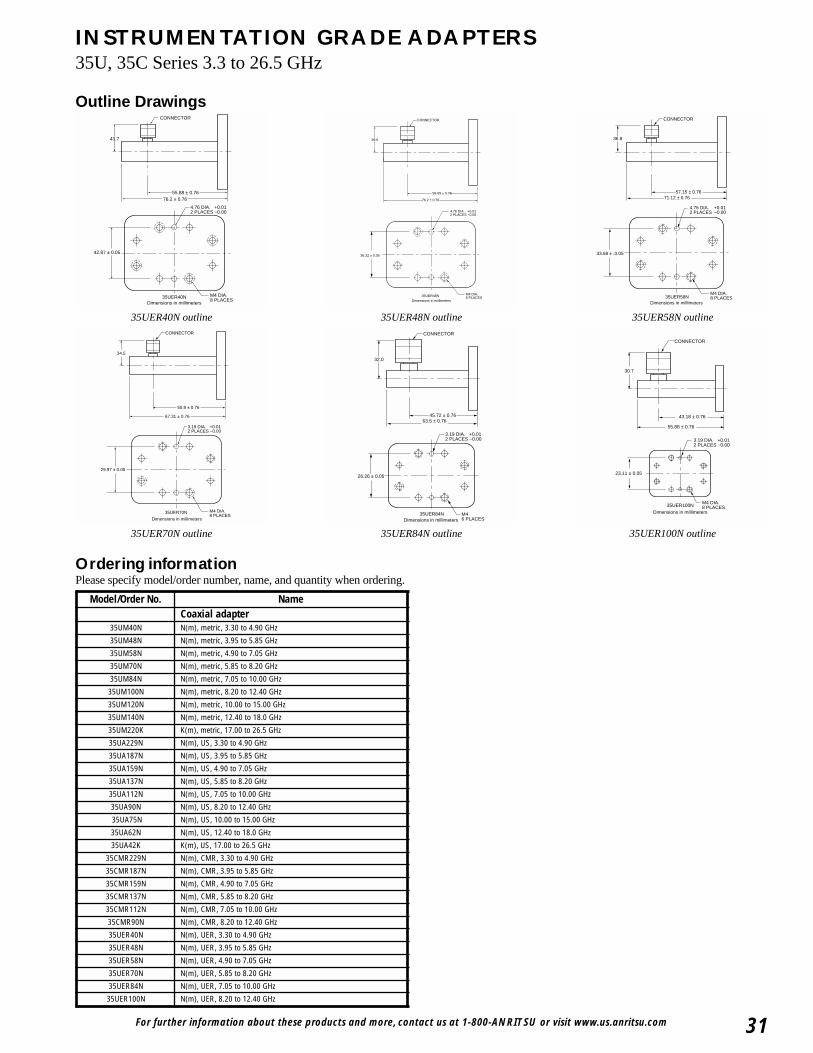
For further information about these products and more, contact us at 1-800-ANRITSU or visit www.us.anritsu.com 31
INSTRUMENTATION GRADE ADAPTERS35U, 35C Series 3.3 to 26.5 GHz
Outline Drawings
M4 DIA.8 PLACES
42.87 ± 0.05
35UER40N
43.7
55.88 ± 0.76 76.2 ± 0.76
Dimensions in millimeters
CONNECTOR
4.76 DIA. +0.01 2 PLACES −0.00
35UER40N outline
M4 DIA.8 PLACES
29.97 ± 0.05
35UER70N
50.8 ± 0.76
67.31 ± 0.76
Dimensions in millimeters
CONNECTOR
34.5
3.19 DIA. +0.012 PLACES –0.00
35UER70N outline
36.32 ± 0.05
35UER48N
39.6
59.69 ± 0.76
Dimensions in millimeters
CONNECTOR
76.2 ± 0.76
M4 DIA.8 PLACES
4.76 DIA . +0.012 PLACES −0.00
35UER48N outline
26.26 ± 0.05
35UER84N
45.72 ± 0.76
Dimensions in millimetersM46 PLACES
32.0
CONNECTOR
63.5 ± 0.76
3.19 DIA. +0.012 PLACES –0.00
35UER84N outline
M4 DIA.8 PLACES
33.68 ± .0.05
35UER58N
71.12 ± 0.76
Dimensions in millimeters
57.15 ± 0.76
36.8
CONNECTOR
4.76 DIA. +0.012 PLACES –0.00
35UER58N outline
M4 DIA.8 PLACES
23.11 ± 0.05
35UER100N
CONNECTOR
30.7
43.18 ± 0.76
55.88 ± 0.76
Dimensions in millimeters
3.19 DIA. +0.012 PLACES −0.00
35UER100N outline
Ordering informationPlease specify model/order number, name, and quantity when ordering.
Model/Order No. NameCoaxial adapter
35UM40N N(m), metric, 3.30 to 4.90 GHz
35UM48N N(m), metric, 3.95 to 5.85 GHz
35UM58N N(m), metric, 4.90 to 7.05 GHz
35UM70N N(m), metric, 5.85 to 8.20 GHz
35UM84N N(m), metric, 7.05 to 10.00 GHz
35UM100N N(m), metric, 8.20 to 12.40 GHz
35UM120N N(m), metric, 10.00 to 15.00 GHz
35UM140N N(m), metric, 12.40 to 18.0 GHz
35UM220K K(m), metric, 17.00 to 26.5 GHz
35UA229N N(m), US, 3.30 to 4.90 GHz
35UA187N N(m), US, 3.95 to 5.85 GHz
35UA159N N(m), US, 4.90 to 7.05 GHz
35UA137N N(m), US, 5.85 to 8.20 GHz
35UA112N N(m), US, 7.05 to 10.00 GHz
35UA90N N(m), US, 8.20 to 12.40 GHz
35UA75N N(m), US, 10.00 to 15.00 GHz
35UA62N N(m), US, 12.40 to 18.0 GHz
35UA42K K(m), US, 17.00 to 26.5 GHz
35CMR229N N(m), CMR, 3.30 to 4.90 GHz
35CMR187N N(m), CMR, 3.95 to 5.85 GHz
35CMR159N N(m), CMR, 4.90 to 7.05 GHz
35CMR137N N(m), CMR, 5.85 to 8.20 GHz
35CMR112N N(m), CMR, 7.05 to 10.00 GHz
35CMR90N N(m), CMR, 8.20 to 12.40 GHz
35UER40N N(m), UER, 3.30 to 4.90 GHz
35UER48N N(m), UER, 3.95 to 5.85 GHz
35UER58N N(m), UER, 4.90 to 7.05 GHz
35UER70N N(m), UER, 5.85 to 8.20 GHz
35UER84N N(m), UER, 7.05 to 10.00 GHz
35UER100N N(m), UER, 8.20 to 12.40 GHz
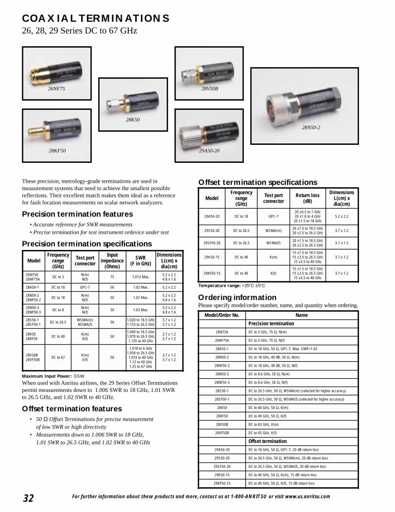
For further information about these products and more, contact us at 1-800-ANRITSU or visit www.us.anritsu.com32
COAXIAL TERMINATIONS26, 28, 29 Series DC to 67 GHz
26NF75
28KF50
28N50-2
28V50B
28K50
29A50-20
These precision, metrology-grade terminations are used inmeasurement systems that need to achieve the smallest possiblereflections. Their excellent match makes them ideal as a referencefor fault location measurements on scalar network analyzers.
Precision termination features• Accurate reference for SWR measurements• Precise termination for test instrument ordevice under test
Precision termination specifications
Maximum Input Power: 0.5 W
When used with Anritsu airlines, the 29 Series Offset Terminationspermit measurements down to 1.006 SWR to 18 GHz, 1.01 SWRto 26.5 GHz, and 1.02 SWR to 40 GHz.
Offset termination features• 50 Ω Offset Terminations for precise measurement
of low SWR or high directivity• Measurements down to 1.006 SWR to 18 GHz,
1.01 SWR to 26.5 GHz, and 1.02 SWR to 40 GHz
Ordering informationPlease specify model/order number, name, and quantity when ordering.
Offset termination specifications
Temperature range: +25°C ±5°C
ModelFrequency
range(GHz)
Test portconnector
Inputimpedance
(Ohms)
SWR (F in GHz)
DimensionsL(cm) xdia(cm)
26N75A26NF75A DC to 3 N(m)
N(f) 75 1.013 Max. 5.2 x 2.24.8 x 1.6
28A50-1 DC to 18 GPC-7 50 1.02 Max. 5.2 x 2.2
28N50-228NF50-2 DC to 18 N(m)
N(f) 50 1.02 Max. 5.2 x 2.24.8 x 1.6
28N50-328NF50-3 DC to 8 N(m)
N(f) 50 1.03 Max. 5.2 x 2.24.8 x 1.6
28S50-128SF50-1 DC to 26.5 WSMA(m)
WSMA(f) 50 1.020 to 18.5 GHz1.153 to 26.5 GHz
3.7 x 1.23.7 x 1.2
28K5028KF50 DC to 40 K(m)
K(f) 501.040 to 18.5 GHz1.070 to 26.5 GHz1.135 to 40 GHz
3.7 x 1.23.7 x 1.2
28V50B28VF50B DC to 67 V(m)
V(f) 50
1.018 to 6 GHz1.058 to 26.5 GHz1.074 to 40 GHz1.12 to 60 GHz1.25 to 67 GHz
3.7 x 1.23.7 x 1.2
Model Frequency
range (GHz)
Test port connector
Return loss (dB)
DimensionsL(cm) xdia(cm)
29A50-20 DC to 18 GPC-720 ±0.5 to 1 GHz20 ±1.0 to 4 GHz20 ±1.5 to 18 GHz
5.2 x 2.2
29S50-20 DC to 26.5 WSMA(m) 20 ±1.5 to 18.5 GHz20 ±2.5 to 26.5 GHz 3.7 x 1.2
29SF50-20 DC to 26.5 WSMA(f) 20 ±1.5 to 18.5 GHz20 ±2.5 to 26.5 GHz 3.7 x 1.2
29K50-15 DC to 40 K(m)15 ±1.5 to 18.5 GHz15 ±2.5 to 26.5 GHz15 ±3.5 to 40 GHz
3.7 x 1.2
29KF50-15 DC to 40 K(f)15 ±1.5 to 18.5 GHz15 ±2.5 to 26.5 GHz15 ±3.5 to 40 GHz
3.7 x 1.2
Model/Order No. Name
Precision termination
26N75A DC to 3 GHz, 75 Ω, N(m)
26NF75A DC to 3 GHz, 75 Ω, N(f)
28A50-1 DC to 18 GHz, 50 Ω, GPC-7, Max. SWR=1.02
28N50-2 DC to 18 GHz, 40 dB, 50 Ω, N(m)
28NF50-2 DC to 18 GHz, 40 dB, 50 Ω, N(f)
28N50-3 DC to 8.6 GHz, 50 Ω, N(m)
28NF50-3 DC to 8.6 GHz, 50 Ω, N(f)
28S50-1 DC to 26.5 GHz, 50 Ω, WSMA(m) (selected for higher accuracy)
28SF50-1 DC to 26.5 GHz, 50 Ω, WSMA(f) (selected for higher accuracy)
28K50 DC to 40 GHz, 50 Ω, K(m)
28KF50 DC to 40 GHz, 50 Ω, K(f)
28V50B DC to 65 GHz, V(m)
28VF50B DC to 65 GHz, V(f)
Offset termination
29A50-20 DC to 18 GHz, 50 Ω, GPC-7, 20 dB return loss
29S50-20 DC to 26.5 GHz, 50 Ω, WSMA(m), 20 dB return loss
29SF50-20 DC to 26.5 GHz, 50 Ω, WSMA(f), 20 dB return loss
29K50-15 DC to 40 GHz, 50 Ω, K(m), 15 dB return loss
29KF50-15 DC to 40 GHz, 50 Ω, K(f), 15 dB return loss
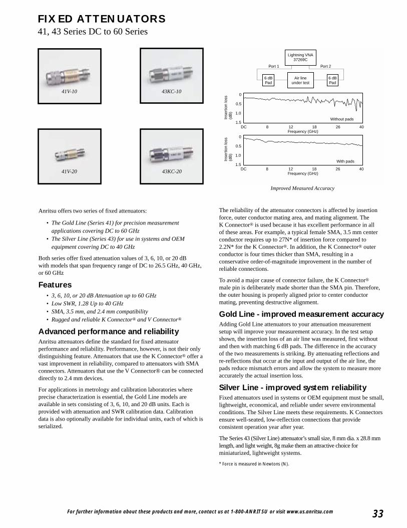
Frequency (GHz)
0
0.5
1.0
1.5
0
0.5
1.0
1.5DC 8 12 18 26 40
Frequency (GHz)DC 8 12 18 26 40
Without pads
With pads
Inse
rtio
n lo
ss(d
B)
Inse
rtio
n lo
ss(d
B)
Air lineunder test
6 dBPad
6 dBPad
Lightning VNA37269C
Port 1 Port 2
For further information about these products and more, contact us at 1-800-ANRITSU or visit www.us.anritsu.com 33
FIXED ATTENUATORS41, 43 Series DC to 60 Series
Anritsu offers two series of fixed attenuators:
• The Gold Line (Series 41) for precision measurementapplications covering DC to 60 GHz
• The Silver Line (Series 43) for use in systems and OEMequipment covering DC to 40 GHz
Both series offer fixed attenuation values of 3, 6, 10, or 20 dBwith models that span frequency range of DC to 26.5 GHz, 40 GHz,or 60 GHz
Features• 3, 6, 10, or 20 dB Attenuation up to 60 GHz• Low SWR, 1.28 Up to 40 GHz• SMA, 3.5 mm, and 2.4 mm compatibility• Rugged and reliable K Connector® and V Connector®
Advanced performance and reliabilityAnritsu attenuators define the standard for fixed attenuatorperformance and reliability. Performance, however, is not their onlydistinguishing feature. Attenuators that use the K Connector® offer avast improvement in reliability, compared to attenuators with SMAconnectors. Attenuators that use the V Connector® can be connecteddirectly to 2.4 mm devices.
For applications in metrology and calibration laboratories whereprecise characterization is essential, the Gold Line models areavailable in sets consisting of 3, 6, 10, and 20 dB units. Each isprovided with attenuation and SWR calibration data. Calibrationdata is also optionally available for individual units, each of which isserialized.
The reliability of the attenuator connectors is affected by insertionforce, outer conductor mating area, and mating alignment. TheK Connector® is used because it has excellent performance in allof these areas. For example, a typical female SMA, 3.5 mm centerconductor requires up to 27N* of insertion force compared to2.2N* for the K Connector®. In addition, the K Connector® outerconductor is four times thicker than SMA, resulting in aconservative order-of-magnitude improvement in the number ofreliable connections.
To avoid a major cause of connector failure, the K Connector®
male pin is deliberately made shorter than the SMA pin. Therefore,the outer housing is properly aligned prior to center conductormating, preventing destructive alignment.
Gold Line - improved measurement accuracyAdding Gold Line attenuators to your attenuation measurementsetup will improve your measurement accuracy. In the test setupshown, the insertion loss of an air line was measured, first withoutand then with matching 6 dB pads. The difference in the accuracyof the two measurements is striking. By attenuating reflections andre-reflections that occur at the input and output of the air line, thepads reduce mismatch errors and allow the system to measure moreaccurately the actual insertion loss.
Silver Line - improved system reliabilityFixed attenuators used in systems or OEM equipment must be small,lightweight, economical, and reliable under severe environmentalconditions. The Silver Line meets these requirements. K Connectorsensure well-seated, low-reflection connections that provideconsistent operation year after year.
The Series 43 (Silver Line) attenuator’s small size, 8 mm dia. x 28.8 mmlength, and light weight, 8g make them an attractive choice forminiaturized, lightweight systems.
* Force is measured in Newtons (N).
Improved Measured Accuracy
41V-10 43KC-10
41V-20 43KC-20
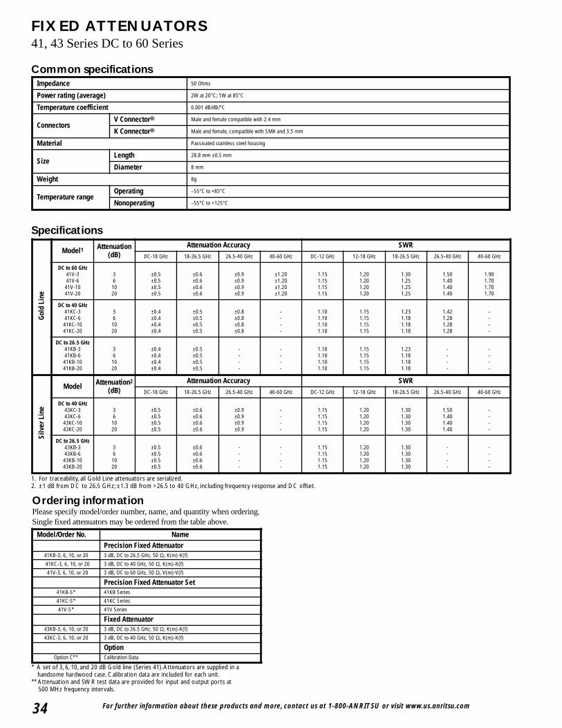
For further information about these products and more, contact us at 1-800-ANRITSU or visit www.us.anritsu.com34
FIXED ATTENUATORS41, 43 Series DC to 60 Series
1. For traceability, all Gold Line attenuators are serialized.2. ±1 dB from DC to 26.5 GHz; ±1.3 dB from >26.5 to 40 GHz, including frequency response and DC offset.
Ordering informationPlease specify model/order number, name, and quantity when ordering.Single fixed attenuators may be ordered from the table above.
* A set of 3, 6, 10, and 20 dB Gold line (Series 41).Attenuators are supplied in ahandsome hardwood case. Calibration data are included for each unit.
** Attenuation and SWR test data are provided for input and output ports at 500 MHz frequency intervals.
Common specifications
Specifications
Impedance 50 Ohms
Power rating (average) 2W at 20°C; 1W at 85°C
Temperature coefficient 0.001 dB/dB/°C
ConnectorsV Connector® Male and female compatible with 2.4 mm
K Connector® Male and female, compatible with SMA and 3.5 mm
Material Passivated stainless steel housing
SizeLength 28.8 mm ±0.5 mm
Diameter 8 mm
Weight 8g
Temperature rangeOperating –55°C to +85°C
Nonoperating –55°C to +125°C
Model/Order No. NamePrecision Fixed Attenuator
41KB-3, 6, 10, or 20 3 dB, DC to 26.5 GHz, 50 Ω, K(m)-K(f)
41KC-3, 6, 10, or 20 3 dB, DC to 40 GHz, 50 Ω, K(m)-K(f)
41V-3, 6, 10, or 20 3 dB, DC to 60 GHz, 50 Ω, V(m)-V(f)
Precision Fixed Attenuator Set41KB-S* 41KB Series
41KC-S* 41KC Series
41V-S* 41V Series
Fixed Attenuator43KB-3, 6, 10, or 20 3 dB, DC to 26.5 GHz, 50 Ω, K(m)-K(f)
43KC-3, 6, 10, or 20 3 dB, DC to 40 GHz, 50 Ω, K(m)-K(f)
OptionOption C** Calibration Data
Gold
Lin
e
Model1 Attenuation(dB)
Attenuation Accuracy SWRDC-18 GHz 18-26.5 GHz 26.5-40 GHz 40-60 GHz DC-12 GHz 12-18 GHz 18-26.5 GHz 26.5-40 GHz 40-60 GHz
DC to 60 GHz41V-341V-641V-1041V-20
361020
±0.5±0.5±0.5±0.5
±0.6±0.6±0.6±0.6
±0.9±0.9±0.9±0.9
±1.20±1.20±1.20±1.20
1.151.151.151.15
1.201.201.201.20
1.301.251.251.25
1.501.401.401.40
1.901.701.701.70
DC to 40 GHz41KC-341KC-641KC-1041KC-20
361020
±0.4±0.4±0.4±0.4
±0.5±0.5±0.5±0.5
±0.8±0.8±0.8±0.8
----
1.101.101.101.10
1.151.151.151.15
1.231.181.181.18
1.421.281.281.28
----
DC to 26.5 GHz41KB-341KB-641KB-1041KB-20
361020
±0.4±0.4±0.4±0.4
±0.5±0.5±0.5±0.5
----
----
1.101.101.101.10
1.151.151.151.15
1.231.181.181.18
----
----
Silv
er L
ine
Model Attenuation2
(dB)Attenuation Accuracy SWR
DC-18 GHz 18-26.5 GHz 26.5-40 GHz 40-60 GHz DC-12 GHz 12-18 GHz 18-26.5 GHz 26.5-40 GHz 40-60 GHz
DC to 40 GHz43KC-343KC-643KC-1043KC-20
361020
±0.5±0.5±0.5±0.5
±0.6±0.6±0.6±0.6
±0.9±0.9±0.9±0.9
----
1.151.151.151.15
1.201.201.201.20
1.301.301.301.30
1.501.401.401.40
----
DC to 26.5 GHz43KB-343KB-643KB-1043KB-20
361020
±0.5±0.5±0.5±0.5
±0.6±0.6±0.6±0.6
----
----
1.151.151.151.15
1.201.201.201.20
1.301.301.301.30
----
----
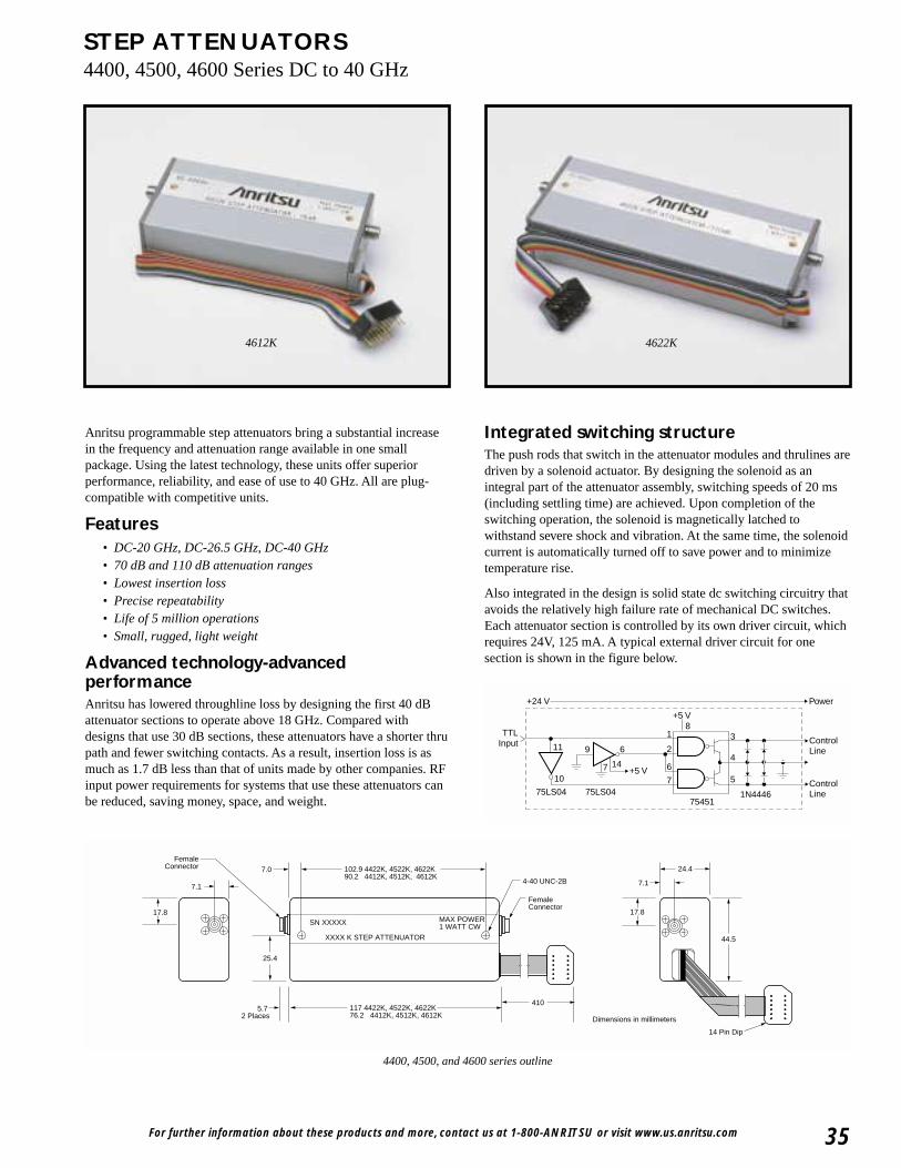
For further information about these products and more, contact us at 1-800-ANRITSU or visit www.us.anritsu.com 35
STEP ATTENUATORS4400, 4500, 4600 Series DC to 40 GHz
Anritsu programmable step attenuators bring a substantial increasein the frequency and attenuation range available in one smallpackage. Using the latest technology, these units offer superiorperformance, reliability, and ease of use to 40 GHz. All are plug-compatible with competitive units.
Features• DC-20 GHz, DC-26.5 GHz, DC-40 GHz• 70 dB and 110 dB attenuation ranges• Lowest insertion loss• Precise repeatability• Life of 5 million operations• Small, rugged, light weight
Advanced technology-advancedperformanceAnritsu has lowered throughline loss by designing the first 40 dBattenuator sections to operate above 18 GHz. Compared withdesigns that use 30 dB sections, these attenuators have a shorter thrupath and fewer switching contacts. As a result, insertion loss is asmuch as 1.7 dB less than that of units made by other companies. RFinput power requirements for systems that use these attenuators canbe reduced, saving money, space, and weight.
Integrated switching structureThe push rods that switch in the attenuator modules and thrulines aredriven by a solenoid actuator. By designing the solenoid as anintegral part of the attenuator assembly, switching speeds of 20 ms(including settling time) are achieved. Upon completion of theswitching operation, the solenoid is magnetically latched towithstand severe shock and vibration. At the same time, the solenoidcurrent is automatically turned off to save power and to minimizetemperature rise.
Also integrated in the design is solid state dc switching circuitry thatavoids the relatively high failure rate of mechanical DC switches.Each attenuator section is controlled by its own driver circuit, whichrequires 24V, 125 mA. A typical external driver circuit for onesection is shown in the figure below.
102.9 4422K, 4522K, 4622K90.2 4412K, 4512K, 4612K
7.1
17.8
7.1
17.8
24.4
44.5
14 Pin Dip
XXXX K STEP ATTENUATOR
SN XXXXX MAX POWER1 WATT CW
117 4422K, 4522K, 4622K76.2 4412K, 4512K, 4612K
FemaleConnector
FemaleConnector
5.7 2 Places
7.0
25.4
4-40 UNC-2B
410
Dimensions in millimeters
4400, 4500, and 4600 series outline
4622K4612K
+5 V
+5 V
83
4
5
ControlLine
ControlLine1N4446
75451
1
2
6
6
7
147
9
10
11
TTLInput
75LS04 75LS04
Power+24 V
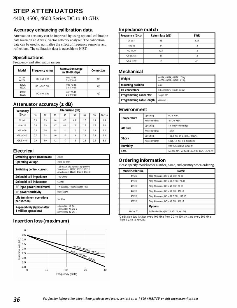
For further information about these products and more, contact us at 1-800-ANRITSU or visit www.us.anritsu.com36
STEP ATTENUATORS4400, 4500, 4600 Series DC to 40 GHz
Accuracy enhancing calibration dataAttenuation accuracy can be improved by using optional calibrationdata taken on an Anritsu vector network analyzer. The calibrationdata can be used to normalize the effect of frequency response andreflections. The calibration data is traceable to NIST.
SpecificationsFrequency and attenuation ranges
Insertion loss (maximum)
Attenuator accuracy (± dB)
Impedance match
Mechanical
Electrical
Ordering informationPlease specify model/order number, name, and quantity when ordering.
0
0
0.5
1.0
4.040
Frequency (GHz)
Inse
rtio
n lo
ss (
dB)
4412K, 4512K, 4612K4422K, 4522K, 4622K
3.5
3.0
2.5
2.0
1.5
10 20 30
*Calibration data is taken every 100 MHz from DC to 900 MHz and every 500 MHzfrom 1 GHz to 40 GHz.
Environment
Model Frequency range Attenuation rangein 10 dB steps Connectors
4412K4422K DC to 20 GHz 0 to 70 dB
0 to 110 dB K(f)
4512K4522K DC to 26.5 GHz 0 to 70 dB
0 to 110 dB K(f)
4612K4622K DC to 40 GHz 0 to 70 dB
0 to 110 dB K(f)
Frequency (GHz)
Attenuation (dB)
10 20 30 40 50 60 70 80-110
DC to 8 0.3 0.5 0.6 0.7 0.8 1.0 1.1 1.4
>8 to 12 0.4 0.5 0.7 0.9 1.0 1.3 1.5 2.0
>12 to 20 0.5 0.6 0.8 1.1 1.2 1.4 1.7 2.2
>20 to 26.5 0.7 0.8 1.0 1.5 1.6 1.9 2.3 2.8
>26.5 to 40 0.9 1.0 1.2 1.7 1.9 2.3 2.6 3.2
Switching speed (maximum) 20 ms
Operating voltage 20 to 30 Volts
Switching control current125 mA at 24V nominal per section3 sections in 4412K, 4512K, 4612K4 sections in 4422K, 4522K, 4622K
Solenoid coil impedance 190 Ohms
Solenoid coil inductance 65 mH
RF input power (maximum) 1W average, 100W peak for 10 µs
RF power sensitivity 0.001 dB/W
Life (minimum operationsper section)
5 million
Repeatability (typical after1 million operations)
±0.03 dB to 18 GHz±0.05 dB to 26.5 GHz±0.08 dB to 40 GHz
Frequency (GHz) Return loss (dB) SWR
DC to 8 19 1.25
>8 to 12 14 1.5
>12 to 20 12.7 1.6
>20 to 26.5 11 1.8
>26.5 to 40 9 2.1
Weight 4412K, 4512K, 4612K: 170g4422K, 4522K, 4622K: 213g
Mounting position Any
RF connectors K Connectors, female, in-line
Programming connector 14 pin DIP
Programming cable length 406 mm
TemperatureOperating: 0C to +70C
Non-operating: -55C to +85C
AltitudeOperating: 4.6 km (440 mm Hg)
Non-operating: 15 km
ShockOperating: 10g, 6 ms, on 6 sides, 3 blows
Non-operating: 500g, 1.8 ms, in 6 directions
Humidity 0 to 95% relative humidity
EMC Mil-Std-461, Method RE02, VDE 0871, CISPR#2
Model/Order No. Name
4412K Step Attenuator, DC to 20 GHz, 70 dB
4512K Step Attenuator, DC to 26.5 GHz, 70 dB
4612K Step Attenuator, DC to 40 GHz, 70 dB
4422K Step Attenuator, DC to 20 GHz, 110 dB
4522K Step Attenuator, DC to 26.5 GHz, 110 dB
4622K Step Attenuator, DC to 40 GHz, 110 dB
Options
Option C* Calibration Data (4412K, 4512K, 4612K)
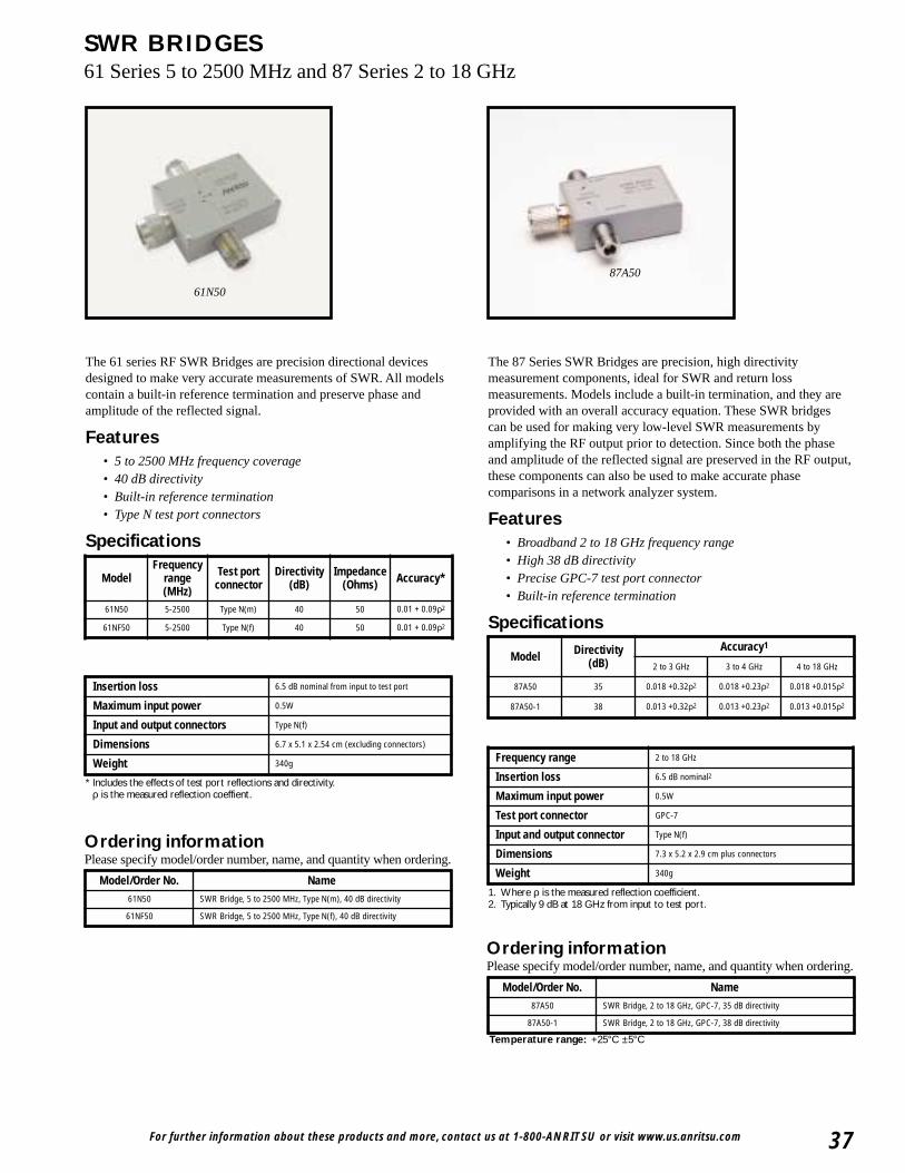
For further information about these products and more, contact us at 1-800-ANRITSU or visit www.us.anritsu.com 37
SWR BRIDGES61 Series 5 to 2500 MHz and 87 Series 2 to 18 GHz
The 87 Series SWR Bridges are precision, high directivitymeasurement components, ideal for SWR and return lossmeasurements. Models include a built-in termination, and they areprovided with an overall accuracy equation. These SWR bridgescan be used for making very low-level SWR measurements byamplifying the RF output prior to detection. Since both the phaseand amplitude of the reflected signal are preserved in the RF output,these components can also be used to make accurate phasecomparisons in a network analyzer system.
Features• Broadband 2 to 18 GHz frequency range• High 38 dB directivity• Precise GPC-7 test port connector• Built-in reference termination
Specifications
The 61 series RF SWR Bridges are precision directional devicesdesigned to make very accurate measurements of SWR. All modelscontain a built-in reference termination and preserve phase andamplitude of the reflected signal.
Features• 5 to 2500 MHz frequency coverage• 40 dB directivity• Built-in reference termination• Type N test port connectors
Specifications
Ordering informationPlease specify model/order number, name, and quantity when ordering.
Ordering informationPlease specify model/order number, name, and quantity when ordering.
87A50
61N50
1. Where ρ is the measured reflection coefficient.2. Typically 9 dB at 18 GHz from input to test port.
* Includes the effects of test port reflections and directivity.ρ is the measured reflection coeffient.
Temperature range: +25°C ±5°C
Model Directivity (dB)
Accuracy1
2 to 3 GHz 3 to 4 GHz 4 to 18 GHz
87A50 35 0.018 +0.32ρ2 0.018 +0.23ρ2 0.018 +0.015ρ2
87A50-1 38 0.013 +0.32ρ2 0.013 +0.23ρ2 0.013 +0.015ρ2
Frequency range 2 to 18 GHz
Insertion loss 6.5 dB nominal2
Maximum input power 0.5W
Test port connector GPC-7
Input and output connector Type N(f)
Dimensions 7.3 x 5.2 x 2.9 cm plus connectors
Weight 340g
Model/Order No. Name87A50 SWR Bridge, 2 to 18 GHz, GPC-7, 35 dB directivity
87A50-1 SWR Bridge, 2 to 18 GHz, GPC-7, 38 dB directivity
Model/Order No. Name61N50 SWR Bridge, 5 to 2500 MHz, Type N(m), 40 dB directivity
61NF50 SWR Bridge, 5 to 2500 MHz, Type N(f), 40 dB directivity
ModelFrequency
range(MHz)
Test portconnector
Directivity(dB)
Impedance(Ohms) Accuracy*
61N50 5-2500 Type N(m) 40 50 0.01 + 0.09ρ2
61NF50 5-2500 Type N(f) 40 50 0.01 + 0.09ρ2
Insertion loss 6.5 dB nominal from input to test port
Maximum input power 0.5W
Input and output connectors Type N(f)
Dimensions 6.7 x 5.1 x 2.54 cm (excluding connectors)
Weight 340g
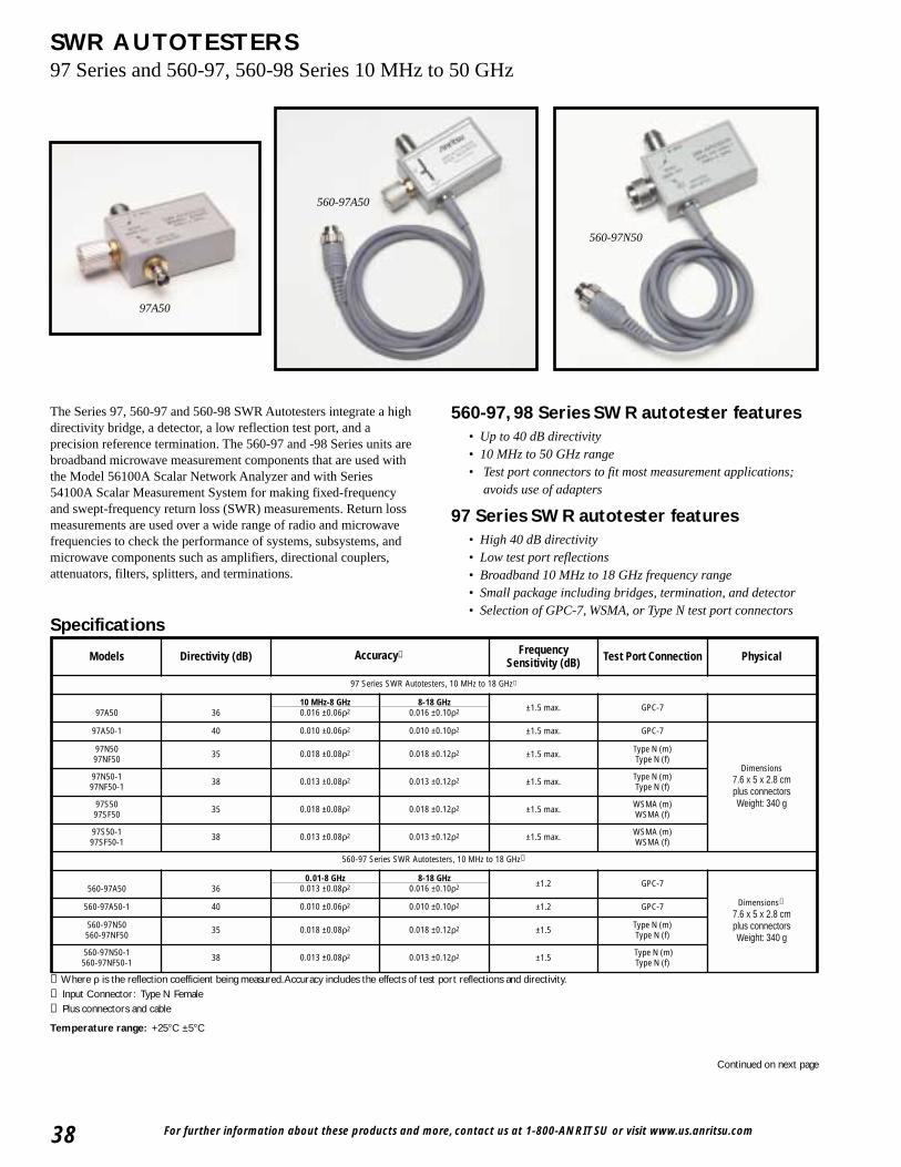
560-97N50
➀ Where ρ is the reflection coefficient being measured.Accuracy includes the effects of test port reflections and directivity.➁ Input Connector: Type N Female➂ Plus connectors and cable
Temperature range: +25°C ±5°C
For further information about these products and more, contact us at 1-800-ANRITSU or visit www.us.anritsu.com38
SWR AUTOTESTERS97 Series and 560-97, 560-98 Series 10 MHz to 50 GHz
97A50
560-97A50
The Series 97, 560-97 and 560-98 SWR Autotesters integrate a highdirectivity bridge, a detector, a low reflection test port, and aprecision reference termination. The 560-97 and -98 Series units arebroadband microwave measurement components that are used withthe Model 56100A Scalar Network Analyzer and with Series54100A Scalar Measurement System for making fixed-frequencyand swept-frequency return loss (SWR) measurements. Return lossmeasurements are used over a wide range of radio and microwavefrequencies to check the performance of systems, subsystems, andmicrowave components such as amplifiers, directional couplers,attenuators, filters, splitters, and terminations.
560-97, 98 Series SWR autotester features• Up to 40 dB directivity• 10 MHz to 50 GHz range • Test port connectors to fit most measurement applications;
avoids use of adapters
97 Series SWR autotester features• High 40 dB directivity• Low test port reflections• Broadband 10 MHz to 18 GHz frequency range• Small package including bridges, termination, and detector• Selection of GPC-7, WSMA, or Type N test port connectors
Specifications
Continued on next page
Models Directivity (dB) Accuracy➀ Frequency Sensitivity (dB) Test Port Connection Physical
97 Series SWR Autotesters, 10 MHz to 18 GHz➁
97A50 3610 MHz-8 GHz0.016 ±0.06ρ2
8-18 GHz0.016 ±0.10ρ2 ±1.5 max. GPC-7
97A50-1 40 0.010 ±0.06ρ2 0.010 ±0.10ρ2 ±1.5 max. GPC-7
Dimensions7.6 x 5 x 2.8 cmplus connectors Weight: 340 g
97N5097NF50 35 0.018 ±0.08ρ2 0.018 ±0.12ρ2 ±1.5 max. Type N (m)
Type N (f)
97N50-197NF50-1 38 0.013 ±0.08ρ2 0.013 ±0.12ρ2 ±1.5 max. Type N (m)
Type N (f)
97S5097SF50 35 0.018 ±0.08ρ2 0.018 ±0.12ρ2 ±1.5 max. WSMA (m)
WSMA (f)
97S50-197SF50-1 38 0.013 ±0.08ρ2 0.013 ±0.12ρ2 ±1.5 max. WSMA (m)
WSMA (f)
560-97 Series SWR Autotesters, 10 MHz to 18 GHz➁
560-97A50 360.01-8 GHz
0.013 ±0.08ρ28-18 GHz
0.016 ±0.10ρ2 ±1.2 GPC-7
Dimensions➂
7.6 x 5 x 2.8 cmplus connectors Weight: 340 g
560-97A50-1 40 0.010 ±0.06ρ2 0.010 ±0.10ρ2 ±1.2 GPC-7
560-97N50560-97NF50 35 0.018 ±0.08ρ2 0.018 ±0.12ρ2 ±1.5 Type N (m)
Type N (f)
560-97N50-1560-97NF50-1 38 0.013 ±0.08ρ2 0.013 ±0.12ρ2 ±1.5 Type N (m)
Type N (f)
For further information about these products and more, contact us at 1-800-ANRITSU or visit www.us.anritsu.com 39
SWR AUTOTESTERS97 Series and 560-97, 560-98 Series 10 MHz to 50 GHz
Ordering informationPlease specify model/order number, name, and quantity when ordering.
All Models:Input Port Impedance: 50Ω Detector Output Polarity: Negative Maximum Power Input: 0.5 watts (+27 dBm) (560-98C50A: +24 dBm)Insertion Loss (from input to test port): 6.5 dB nominal Output Time Constant: 2 ms Cable Length: 122 cm (4 ft.)
➀ Where ρ is the reflection coefficient being measured.Accuracy includes the effects of test port reflections and directivity.➁ Input Connector: Ruggedized Type K Female➂ Input Connector: Ruggedized Type V Female➃ Plus connectors and cable➄ When used with 18A50 Airline➅ When used with 19K50 Airline
Models Directivity (dB) Accuracy➀ Freq. Sensitivity (dB)
Test Port Connection Physical
560-98 Series SWR Autotesters, 10 MHz to 40 GHz➁
560-98S50560-98SF50
3736
0.01-8 GHz 8-18 GHz0.014 ±0.01ρ2
18-26.5 GHz
0.016 ±0.13ρ2
26.5-40 GHz±2.0 WSMA (m)
WSMA (f)
Dimensions➃ :1.9 x 3.8 x 2.9 cm
Weight: 198 g
560-98S50-1560-98SF50-1
4038
0.010 ±0.07ρ2 0.010 ±0.01ρ2
0.013 ±0.13ρ2 ±2.0 WSMA (m)WSMA (f)
560-98K50560-98KF50
353230
0.018 ±0.07ρ2 0.018 ±0.07ρ2
0.026 ±0.15ρ2
0.032 ±0.18ρ2±3.0 Type K (m)
Type K (f)
560-98 Series SWR Autotesters, 10 MHz to 50 GHz➂
560-98VA50560-98VFA50 30
0.01-50 GHz
0.032 ±0.11ρ2 ±4.0Type V (m)Type V (f)
Dimensions➃ :2.2 x 6.6 x 5.3 cm
Weight: 198 g
560-97, 560-98 Offset SWR autotesters, 10 Mhz to 40 GHz
560-97A50-20 20
500 MHz-18 GHz➄
0.0015±2.5
GPC-7
Dimensions➃ :7.6 x 5.1 x 2.8 cm
Weight: 340 g
560-98KF50-15 15
800 MHz-40 GHz➅
0.0100 ±4.0 Type K (m)
Dimensions➃ :2.2 x 6.6 x 5.3 cm
Weight: 198 g
Model/Order No. Name
SWR Autotester
97A50 10 MHz to 18 GHz, GPC-7, 36 dB directivity
97A50-1 10 MHz to 18 GHz, GPC-7, 40 dB directivity
97N50 10 MHz to 18 GHz, N(m), 35 dB directivity
97N50-1 10 MHz to 18 GHz, N(m), 38 dB directivity
97NF50 10 MHz to 18 GHz, N(f), 35 dB directivity
97NF50-1 10 MHz to 18 GHz, N(f), 38 dB directivity
97S50 10 MHz to 18 GHz, WSMA(m), 35 dB directivity
97S50-1 10 MHz to 18 GHz, WSMA(m), 38 dB directivity
97SF50 10 MHz to 18 GHz, WSMA(f), 35 dB directivity
97SF50-1 10 MHz to 18 GHz, WSMA(f), 38 dB directivity
560-97A50 10 MHz to 18 GHz, GPC-7, 50 Ω, 36 dB directivity
560-97A50-1 10 MHz to 18 GHz, GPC-7, 50 Ω, 40 dB directivity
560-97N50 10 MHz to 18 GHz, N(m), 50 Ω, 35 dB directivity
560-97N50-1 10 MHz to 18 GHz, N(m), 50 Ω, 38 dB directivity
560-97NF50 10 MHz to 18 GHz, N(f), 50 Ω, 35 dB directivity
560-97NF50-1 10 MHz to 18 GHz, N(f), 50 Ω, 38 dB directivity
Model/Order No. Name
SWR Autotester
560-98S50 10 MHz-26.5 GHz, WSMA(m), 50 Ω, directivity = 37 dB (<18 GHz),36 dB (18 GHz)
560-98S50-1 10 MHz-26.5 GHz, WSMA(m), 50 Ω, directivity = 40 dB (<18 GHz),38 dB (18 GHz)
560-98SF50 10 MHz-26.5 GHz, WSMA(f), 50 Ω, directivity = 37 dB (< 18 GHz),36 dB (18 GHz)
560-98SF50-1 10 MHz-26.5 GHz, WSMA(f), 50 Ω, directivity = 40 dB (< 18 GHz),38 dB (18 GHz)
560-98K50 10 MHz-40 GHz, K(m), 50 Ω, directivity = 35 dB (<18 GHz), 32 dB (18 to 26.5 GHz), 30 dB (26.5 GHz)
560-98KF50 10 MHz-40 GHz, K(f), 50 Ω, directivity = 35 dB (<18 GHz), 32 dB (18 to 26.5 GHz), 30 dB (26.5 GHz)
560-98VA50 10 MHz-50 GHz, V(m), 50 Ω, directivity = 36 dB (<20 GHz), 30 dB (20 GHz)
560-98VFA50 10 MHz-50 GHz, V(m), 50 Ω, directivity = 36 dB (<20 GHz), 30 dB (20 GHz)
Offset SWR Autotester
560-97A50-20 10 MHz to 18 GHz, GPC-7, 20 dB offset reference in bridge
560-98KF50-15 10 MHz to 40 GHz, K(f), 15 dB offset reference in bridge
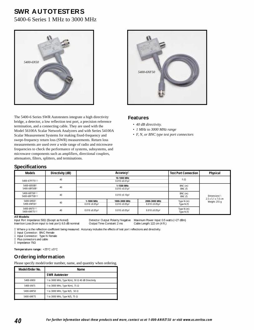
For further information about these products and more, contact us at 1-800-ANRITSU or visit www.us.anritsu.com40
SWR AUTOTESTERS5400-6 Series 1 MHz to 3000 MHz
5400-6N50
5400-6NF50
The 5400-6 Series SWR Autotesters integrate a high directivitybridge, a detector, a low reflection test port, a precision referencetermination, and a connecting cable. They are used with theModel 56100A Scalar Network Analyzers and with Series 54100AScalar Measurement Systems for making fixed-frequency and swept-frequency return loss (SWR) measurements. Return lossmeasurements are used over a wide range of radio and microwavefrequencies to check the performance of systems, subsystems, andmicrowave components such as amplifiers, directional couplers,attenuators, filters, splitters, and terminations.
All Models:Input Port Impedance: 50Ω (Except as Noted) Detector Output Polarity: Negative Maximum Power Input: 0.5 watts (+27 dBm) Insertion Loss (from input to test port): 6.5 dB nominal Output Time Constant: 2 ms Cable Length: 122 cm (4 ft.)
➀ Where ρ is the reflection coefficient being measured. Accuracy includes the effects of test port reflections and directivity.➁ Input Connector: BNC Female➂ Input Connector: Type N Female➃ Plus connectors and cable➄ Impedance 75Ω
Temperature range: +25°C ±5°C
Ordering informationPlease specify model/order number, name, and quantity when ordering.
Features• 40 dB directivity.• 1 MHz to 3000 MHz range• F, N, or BNC type test port connectors
SpecificationsModels Directivity (dB) Accuracy➀ Test Port Connection Physical
5400-67FF75➁➄ 40 10-1000 MHz0.010 ±0.01ρ2 F (f)
5400-6B50B➂
5400-6BF50B➂ 40 1-1500 MHz0.010 ±0.01ρ2
BNC (m)BNC (f)
Dimensions➃ : 2.5 x 5.1 x 7.0 cm
Weight: 255 g
5400-6B75B➂➄
5400-6BF75B➂➄ 40 0.010 ±0.10ρ2 BNC (m)BNC (f)
5400-6N50➂
5400-6NF50➂ 40 1-1000 MHz0.010 ±0.05ρ2
1000-3000 MHz0.010 ±0.05ρ2
2000-3000 MHz0.010 ±0.05ρ2
Type N (m)Type N (f)
5400-6N75➂➄
5400-6NF75➂➄ 40 0.010 ±0.05ρ2 0.010 ±0.05ρ2 0.010 ±0.05ρ2 Type N (m)Type N (f)
Model/Order No. Name
SWR Autotester
5400-6N50 1 to 3000 MHz, Type N(m), 50 Ω 40 dB Directivity
5400-6N75 1 to 3000 MHz, Type N(m), 75 Ω
5400-6NF50 1 to 3000 MHz, Type N(f), 50 Ω
5400-6NF75 1 to 3000 MHz, Type N(f), 75 Ω
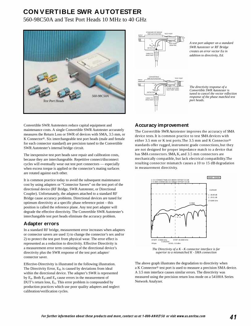
For further information about these products and more, contact us at 1-800-ANRITSU or visit www.us.anritsu.com 41
CONVERTIBLE SWR AUTOTESTER560-98C50A and Test Port Heads 10 MHz to 40 GHz
560-98C50A
Test Port Heads
INPUT
DUT
CABLE TOANALYZER
DETECTOR
STANDARD RF BRIDGE SWR AUTOTESTOR TEST PORT
TEST PORTADAPTER
Zx
EaEd Ex
INPUT
CABLE TOANALYZER
DETECTOR
CONVERTIBLESWR AUTOTESTOR TEST PORT
PHASE MATCHEDTEST PORT HEAD
Ea
Ed Ex
A test port adapter on a standardSWR Autotester or RF Bridgecreates an error vector Ea inaddition to directivity, Ed.
The directivity response of aConvertible SWR Autotester istuned to cancel the vector reflectionresponse of the phase matched testport heads.
Convertible SWR Autotesters reduce capital equipment andmaintenance costs. A single Convertible SWR Autotester accuratelymeasures the Return Loss or SWR of devices with SMA, 3.5 mm, orK Connector®. Six interchangeable test port heads (male and femalefor each connector standard) are precision tuned to the ConvertibleSWR Autotester’s internal bridge circuit.
The inexpensive test port heads save repair and calibration costs,because they are interchangeable. Repetitive connect/disconnectcycles will eventually wear out test port connectors — especiallywhen excess torque is applied or the connector’s mating surfacesare rotated against each other.
It is common practice today to avoid the subsequent maintenancecost by using adapters or “Connector Savers” on the test port of thedirectional device (RF Bridge, SWR Autotester, or DirectionalCoupler). Unfortunately, the adapters attached to a standard RFBridge cause accuracy problems. Directional devices are tuned foroptimum directivity at a specific phase reference point – thisposition is called the reference plane. Any test port adapter willdegrade the effective directivity. The Convertible SWR Autotester’sinterchangable test port heads eliminate the accuracy problem.
Adapter errorsIn a standard RF bridge, measurement error increases when adaptersor connector savers are used 1) to change the connector’s sex and/or2) to protect the test port from physical wear. The error effect isrepresented as a reduction to directivity. Effective Directivity isa measurement error term consisting of the directional device’sdirectivity plus the SWR response of the test port adapter/connector saver.
Effective-Directivity is illustrated in the following illustration.The Directivity Error, Ed, is caused by deviations from idealwithin the directional device. The adapter’s SWR is representedby Ea. Both Ed and Ea cause errors in the measurement ofDUT’s return loss, Ex. This error problem is compounded byproduction practices which use poor quality adapters and neglectcalibration/verification cycles.
Accuracy improvementThe Convertible SWR Autotester improves the accuracy of SMAdevice tests. It is common practice to test SMA devices witheither 3.5 mm or K test ports.The 3.5 mm and K Connector®
standards offer rugged, instrument grade connections, but theyare not designed for proper impedance match to a device thathas SMA connectors. SMA, K, and 3.5 mm connectors aremechanically compatible, but lack electrical compatibility.Theresulting connector mismatch causes a 10 to 15 dB degradationin measurement directivity.
The above graph illustrates the degradation to directivity whena K Connector® test port is used to measure a precision SMA device.A 3.5 mm interface causes similar errors. The directivity wasmeasured using the precision return loss mode on a 54100A SeriesNetwork Analyzer.
Model: 54169A
2: K-SMA CONNEC(B) 10.0 dB/DIV OFFSET 0.0 dB1: K-K CONNECTN(B) 10.0 dB/DIV OFFSET 0.0 dB
START: 0.5000 GHz STOP: 40.0000 GHz5 GHz/DIV
401pts LEVEL: 0.0 dBm
CURSOR
1: -38.89 dB
2: -29.51 dB
17.6286 GHz
2
1
K-SMA
K - K
The Directivity of a K - K connector interface is far superior to a mismatched K - SMA connection
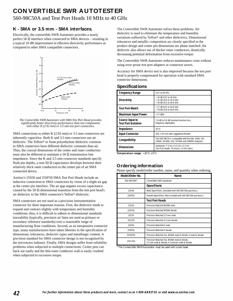
For further information about these products and more, contact us at 1-800-ANRITSU or visit www.us.anritsu.com42
CONVERTIBLE SWR AUTOTESTER560-98C50A and Test Port Heads 10 MHz to 40 GHz
K - SMA or 3.5 mm - SMA interfaces.Electrically, the convertible SWR Autotester provides a nearlyperfect 50 Ω interface when connected to SMA devices – resulting ina typical 10 dB improvement in effective directivity performance ascompared to other SMA compatible connectors.
0.01 10 20 30Frequency, GHz
-30
-40
-60
Con
nect
or In
terf
ace
Ret
urn
Loss
, dB
-50
-20
-10
0
K (2.92 mm) to SMAInterface
3.5 mm to SMAInterface
SMA to SMAInterface
The Convertible SWR Autotester with SMA Test Port Head providessignificantly better directivity performance than test components
with either K (2.92 mm) or 3.5 mm test port connectors.
SMA connections to either K (2.92 mm) or 3.5 mm connectors areinherently capacitive. Both K and 3.5 mm connectors use airdielectric. The Teflon® or foam polyethylene dielectric commonto SMA connectors have different dielectric constants than air.Thus, the coaxial dimensions of the center and outer conductorsmust also be different to maintain a 50 Ω transmission lineimpedance. Since the K and 3.5 mm connector standards specifyflush pin depths, a non-50 Ω capacitance develops between theirrelatively thick outer conductors to the center pin of an SMAconnected device.
Anritsu’s 25S50 and 25SF50 SMA Test Port Heads include aninductive connection to SMA connectors by virtue of a slight air gapat the center pin interface. The air gap negates excess capacitancecaused by the 50 Ω dimensional transition from the test port head'sair dielectric to the SMA connector's Teflon® dielectric.
SMA connectors are not used as a precision instrumentationconnector for three important reasons. First, the dielectric tends toexpand and contract slightly with temperature and humidityconditions; thus, it is difficult to adhere to dimensional standardstraceability (typically, precision air lines are used as primary orsecondary reference standards) over a reasonable range ofmanufacturing floor conditions. Second, as an inexpensive connectortype, many manufacturers have taken liberties in the specification ofdimensions, tolerances, dielectric types and metallurgic content. Aprecision standard for SMA connector design is not recognized bythe microwave industry. Finally, SMA designs suffer from reliabilityproblems when subjected to multiple connections. Center pins canback out easily and the thin outer conductor wall is easily crushedwhen subjected to excessive torque.
* The Convertible SWR Autotester must be used with a test head.
Ordering informationPlease specify model/order number, name, and quantity when ordering.
The Convertible SWR Autotester solves these problems. Airdielectric is used to eliminate the temperature and humidityvariations suffered by Teflon® and other dielectrics. Dimensionaltolerances and metallic composition are clearly specified in theproduct design and center pin dimensions are phase matched. Airdielectric also allows use of thicker outer conductors, drasticallydecreasing potential deformation from excessive torque.
The Convertible SWR Autotester reduces maintenance costs withoutusing error prone test port adapters or connector savers.
Accuracy for SMA device test is also improved because the test porthead is properly compensated for operation with standard SMAconnector dimensions.
Specifications
Temperature range: +25°C ±5°C
Frequency Range 0.01 to 40 GHz
Directivity> 34 dB 0.01 to 20 GHz> 32 dB 20.0 to 26.5 GHz> 29 dB 26.5 to 40.0 GHz
Test Port Match > 21 dB 0.01 to 20.0 GHz> 18 dB 20.0 to 40.0 GHz
Maximum Input Power + 27 dBm
Source Input to Test Port Isolation
7.0 dB to 9.0 dB nominal insertion loss, frequency dependent.
Impedance 50 Ω
Input Connector K(f), 2.92 mm with ruggedized threads
Compatibility The 560-98C50 is compatible with the 560, 560A, 561,5400A, 56100A, 562, 54100A and 54000A analyzers.
Dimensions Autotester: 7.3 cm x 5.3 cm x 2.3 cmTest Port Heads: 16 mm(L) x 9 mm (dia.)
Model/Order No. Name
560-98C50A* Convertible SWR Autotester
Open/Shorts
22K50 Male Open/Short, (Included with 560-98C50A purchase.)
22KF50 Female Open/Short, (Not included with 560-98C50A purchase.)
Test Port Heads
25S50 Precision Matched WSMA male
25SF50 Precision Matched WSMA female
25L50 Precision Matched 3.5 mm male
25LF50 Precision Matched 3.5 mm female
25K50 Precision Matched K male
25KF50 Precision Matched K female
25SKF50 Precision Matched Set, WSMA male & female, K male & female
25SLF50 Precision Matched Set, WSMA male & female,3.5 mm male & female, K Connctor male & female
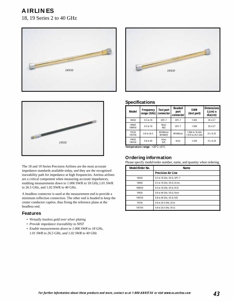
For further information about these products and more, contact us at 1-800-ANRITSU or visit www.us.anritsu.com 43
AIRLINES18, 19 Series 2 to 40 GHz
The 18 and 19 Series Precision Airlines are the most accurateimpedance standards available today, and they are the recognizedtraceability path for impedance at high frequencies. Anritsu airlinesare a critical component when measuring accurate impedances,enabling measurements down to 1.006 SWR to 18 GHz,1.01 SWRto 26.5 GHz, and 1.02 SWR to 40 GHz.
A beadless connector is used at the measurement end to provide aminimum reflection connection. The other end is beaded to keep thecenter conductor captive, thus fixing the reference plane at thebeadless end.
Features• Virtually lossless gold over silver plating• Provide impedance traceability to NIST• Enable measurements down to 1.006 SWR to 18 GHz,
1.01 SWR to 26.5 GHz, and 1.02 SWR to 40 GHz
Ordering informationPlease specify model/order number, name, and quantity when ordering.
Specifications
18N50 18A50
19S50
Temperature range: +25°C ±5°C
Model Frequencyrange (GHz)
Test portconnector
Beadedport
connector
SWR(test port)
DimensionsL(cm) xdia(cm)
18A50 0.5 to 18 GPC-7 GPC-7 1.003 30 x 0.7
18N5018NF50 0.5 to 18 N(m)
N(f) GPC-7 1.006 30 x 0.7
19S5019SF50 0.8 to 26.5 WSMA(m)
WSMA(f) WSMA(m) 1.006 to 18 GHz1.010 to 26.5 GHz 25 x 0.35
19K5019KF50 0.8 to 40 K(m)
K(f) K(m) 1.020 15 x 0.29
Model/Order No. Name
Precision Air Line
18A50 0.5 to 18 GHz, 50 Ω, GPC-7
18N50 0.5 to 18 GHz, 50 Ω, N (m)
18NF50 0.5 to 18 GHz, 50 Ω, N (f)
19K50 0.8 to 40 GHz, 50 Ω, K(m)
19KF50 0.8 to 40 GHz, 50 Ω, K(f)
19S50 0.8 to 26.5 GHz, 50 Ω
19SF50 0.8 to 26.5 GHz, 50 Ω
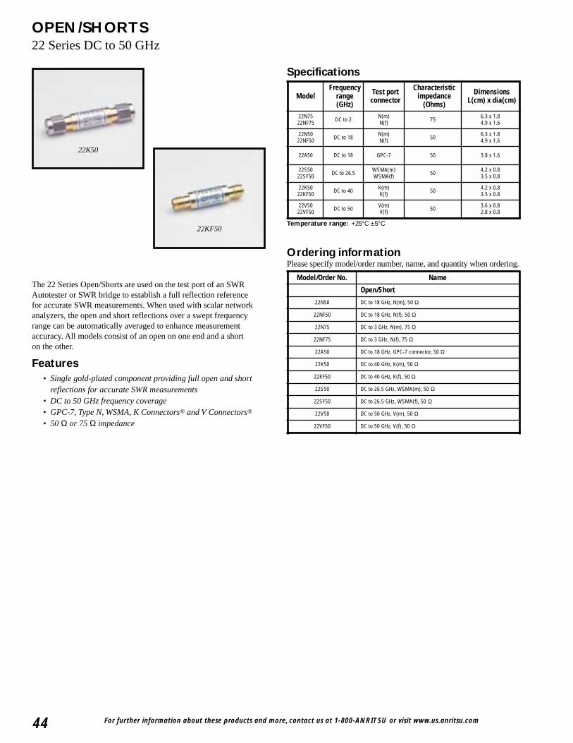
For further information about these products and more, contact us at 1-800-ANRITSU or visit www.us.anritsu.com44
OPEN/SHORTS22 Series DC to 50 GHz
22K50
22KF50
The 22 Series Open/Shorts are used on the test port of an SWRAutotester or SWR bridge to establish a full reflection referencefor accurate SWR measurements. When used with scalar networkanalyzers, the open and short reflections over a swept frequencyrange can be automatically averaged to enhance measurementaccuracy. All models consist of an open on one end and a shorton the other.
Features• Single gold-plated component providing full open and short
reflections for accurate SWR measurements• DC to 50 GHz frequency coverage• GPC-7, Type N, WSMA, K Connectors® and V Connectors®
• 50 Ω or 75 Ω impedance
Specifications
Ordering informationPlease specify model/order number, name, and quantity when ordering.
Temperature range: +25°C ±5°C
ModelFrequency
range (GHz)
Test portconnector
Characteristicimpedance
(Ohms)
DimensionsL(cm) x dia(cm)
22N7522NF75 DC to 2 N(m)
N(f) 75 6.3 x 1.84.9 x 1.6
22N5022NF50 DC to 18 N(m)
N(f) 50 6.3 x 1.84.9 x 1.6
22A50 DC to 18 GPC-7 50 3.8 x 1.6
22S5022SF50 DC to 26.5 WSMA(m)
WSMA(f) 50 4.2 x 0.83.5 x 0.8
22K5022KF50 DC to 40 K(m)
K(f) 50 4.2 x 0.83.5 x 0.8
22V5022VF50 DC to 50 V(m)
V(f) 50 3.6 x 0.82.8 x 0.8
Model/Order No. Name
Open/Short
22N50 DC to 18 GHz, N(m), 50 Ω
22NF50 DC to 18 GHz, N(f), 50 Ω
22N75 DC to 3 GHz, N(m), 75 Ω
22NF75 DC to 3 GHz, N(f), 75 Ω
22A50 DC to 18 GHz, GPC-7 connector, 50 Ω
22K50 DC to 40 GHz, K(m), 50 Ω
22KF50 DC to 40 GHz, K(f), 50 Ω
22S50 DC to 26.5 GHz, WSMA(m), 50 Ω
22SF50 DC to 26.5 GHz, WSMA(f), 50 Ω
22V50 DC to 50 GHz, V(m), 50 Ω
22VF50 DC to 50 GHz, V(f), 50 Ω
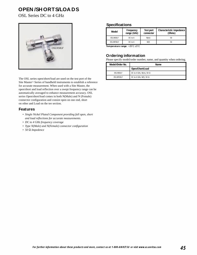
For further information about these products and more, contact us at 1-800-ANRITSU or visit www.us.anritsu.com 45
OPEN/SHORTS/LOADSOSL Series DC to 4 GHz
OSLN50LF
The OSL series open/short/load are used on the test port of theSite Master™ Series of handheld instruments to establish a referencefor accurate measurement. When used with a Site Master, theopen/short and load reflection over a swept frequency range can beautomatically averaged to enhance measurement accuracy. OSLseries Open/short/load comes in both N(Male) and N (Female)connector configuration and consist open on one end, shorton other and Load on the tee section.
Features• Single Nickel Plated Component providing full open, short
and load reflections for accurate measurements.• DC to 4 GHz frequency coverage• Type N(Male) and N(Female) connector configuration• 50 Ω Impedence
Ordering informationPlease specify model/order number, name, and quantity when ordering.
Specifications
Temperature range: +25°C ±5°C
Model/Order No. Name
Open/Short/Load
OSLN50LF DC to 4 GHz, N(m), 50 Ω
OSLNF50LF DC to 4 GHz, N(f), 50 Ω
Model Frequency range (GHz)
Test portconnector
Characteristic impedance(Ohms)
OSLN50LF DC to 4 N(m) 50
OSLNF50LF DC to 4 N(f) 50
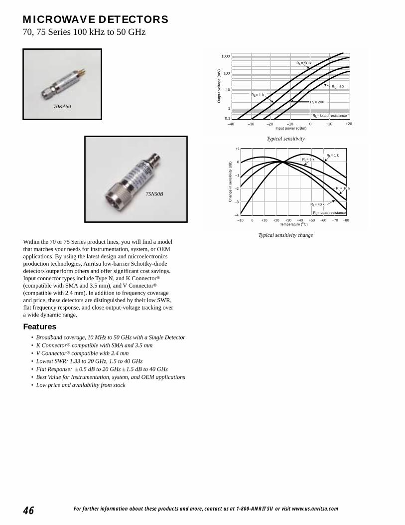
For further information about these products and more, contact us at 1-800-ANRITSU or visit www.us.anritsu.com46
MICROWAVE DETECTORS70, 75 Series 100 kHz to 50 GHz
Within the 70 or 75 Series product lines, you will find a modelthat matches your needs for instrumentation, system, or OEMapplications. By using the latest design and microelectronicsproduction technologies, Anritsu low-barrier Schottky-diodedetectors outperform others and offer significant cost savings.Input connector types include Type N, and K Connector®
(compatible with SMA and 3.5 mm), and V Connector®
(compatible with 2.4 mm). In addition to frequency coverageand price, these detectors are distinguished by their low SWR,flat frequency response, and close output-voltage tracking overa wide dynamic range.
Features• Broadband coverage, 10 MHz to 50 GHz with a Single Detector• K Connector® compatible with SMA and 3.5 mm• V Connector® compatible with 2.4 mm• Lowest SWR: 1.33 to 20 GHz, 1.5 to 40 GHz• Flat Response: ±0.5 dB to 20 GHz ±1.5 dB to 40 GHz• Best Value for Instrumentation, system, and OEM applications• Low price and availability from stock
RL= Load resistance
RL= 50
RL= 50 k
RL= 1 k
RL= 200
10
1
0.1
–10–20–30–40
Out
put v
olta
ge (
mV
)
0 +10 +20Input power (dBm)
1000
100
+1
0
–1
–2
–3
–4–10 0 +10 +20 +30 +40 +50 +60 +70 +80
Temperature (˚C)
Cha
nge
in s
ensi
tivity
(dB
)
RL= Load resistance
RL= 40 k
RL= 10 k
RL= 1 k RL= 5 k
Typical sensitivity
Typical sensitivity change
75N50B
70KA50
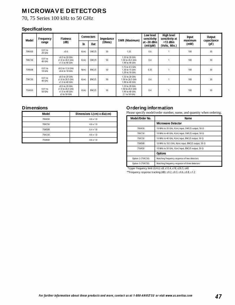
For further information about these products and more, contact us at 1-800-ANRITSU or visit www.us.anritsu.com 47
MICROWAVE DETECTORS70, 75 Series 100 kHz to 50 GHz
Dimensions Ordering informationPlease specify model/order number, name, and quantity when ordering.
*Upper frequency limit (GHz): ≤8, ≤12.4, ≤18, ≤26.5, ≤40**Frequency response tracking (dB): ±0.2, ±0.3, ±0.6, ±0.8, ±1.2
Specifications
Model Frequencyrange
Flatness(dB)
ConnectorsImpedance
(Ohms) SWR (Maximum)
Low levelsensitivityat –30 dBm
(mV/µW)
High levelsensitivity at
+13 dBm(Volts, Min.)
Input maximum
(mW)
Outputcapacitance
(pF)In Out
70KA50 0.01 to 20 GHz ±0.6 K(m) SMC(f) 50 1.33 0.6 1 100 30
70KC50 0.01 to 40 GHz
±0.5 to 20 GHz±1.0 to 26.5 GHz±1.5 to 40 GHz
K(m) SMC(f) 501.33 to 20 GHz
1.50 to 26.5 GHz1.90 to 40 GHz
0.4 1 100 30
75N50B 0.01 to 18 GHz
±0.3 to 12.4 GHz±0.6 to 18 GHz N(m) BNC(f) 50
1.15 to 4.5 GHz1.30 to 15 GHz1.39 to 18 GHz
0.35 1 100 30
75KC50 0.01 to 40 GHz
±0.5 to 20 GHz±1.0 to 26.5 GHz±1.5 to 40 GHz
K(m) BNC(f) 501.33 to 20 GHz
1.50 to 26.5 GHz1.90 to 40 GHz
0.4 1 100 30
75VA50 0.01 to 50 GHz
±0.5 to 20 GHz±1.0 to 26.5 GHz±1.5 to 40 GHz±3 to 50 GHz
V(m) BNC(f) 50
1.33 to 20 GHz1.50 to 26.5 GHz1.90 to 40 GHz2.1 to 50 GHz
0.4 1 100 30
Model Dimensions L(cm) x dia(cm)
70KA50 4.6 x 1.0
70KC50 4.6 x 1.0
75N50B 6.4 x 1.8
75KC50 4.6 x 1.0
75VA50 4.6 x 1.0
Model/Order No. Name
Microwave Detector
70KA50 10 MHz to 20 GHz, K(m) input, SMC(f) output, 50 Ω
70KC50 10 MHz to 40 GHz, K(m) input, SMC(f) output, 50 Ω
75KC50 10 MHz to 40 GHz, K(m) input, BNC(f) output, 50 Ω
75N50B 10 MHz to 18.5 GHz, N(m) input, BNC(f) output, 50 Ω
75VA50 10 MHz to 50 GHz, V(m) input, BNC(f) output, 50 Ω
Options
Option 2 (75KC50) Matching frequency response of two detectors
Option 3 (75KC50) Matching frequency response of three detectors
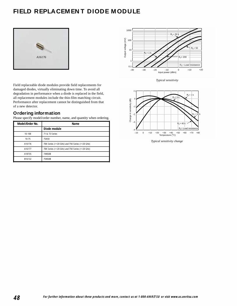
For further information about these products and more, contact us at 1-800-ANRITSU or visit www.us.anritsu.com48
FIELD REPLACEMENT DIODE MODULE
A16176
RL= Load resistance
RL= 50
RL= 50 k
RL= 1 k
RL= 200
10
1
0.1
–10–20–30–40
Out
put v
olta
ge (
mV
)
0 +10 +20Input power (dBm)
1000
100
+1
0
–1
–2
–3
–4–10 0 +10 +20 +30 +40 +50 +60 +70 +80
Temperature (˚C)
Cha
nge
in s
ensi
tivity
(dB
)RL= Load resistance
RL= 40 k
RL= 10 k
RL= 1 k RL= 5 k
Typical sensitivity
Typical sensitivity change
Field replaceable diode modules provide field replacements fordamaged diodes, virtually eliminating down time. To avoid alldegradation in performance when a diode is replaced in the field,all replacement modules include the thin-film matching circuit.Performance after replacement cannot be distinguished from thatof a new detector.
Ordering informationPlease specify model/order number, name, and quantity when ordering.
Model/Order No. Name
Diode module
10-108 71 & 73 Series
10-75 75A50
A16176 70K Series (>=20 GHz) and 75K Series (>=20 GHz)
A16177 70K Series (<=20 GHz) and 75K Series (<=20 GHz)
A18735 74N50B
B16132 75N50B
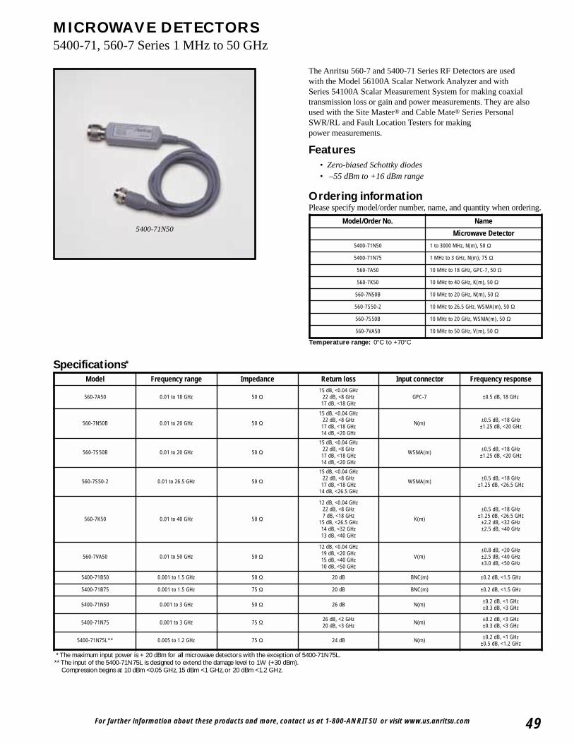
For further information about these products and more, contact us at 1-800-ANRITSU or visit www.us.anritsu.com 49
MICROWAVE DETECTORS5400-71, 560-7 Series 1 MHz to 50 GHz
The Anritsu 560-7 and 5400-71 Series RF Detectors are usedwith the Model 56100A Scalar Network Analyzer and withSeries 54100A Scalar Measurement System for making coaxialtransmission loss or gain and power measurements. They are alsoused with the Site Master® and Cable Mate® Series PersonalSWR/RL and Fault Location Testers for makingpower measurements.
Features• Zero-biased Schottky diodes• –55 dBm to +16 dBm range
Specifications*
* The maximum input power is + 20 dBm for all microwave detectors with the exception of 5400-71N75L.** The input of the 5400-71N75L is designed to extend the damage level to 1W (+30 dBm).
Compression begins at 10 dBm <0.05 GHz, 15 dBm <1 GHz, or 20 dBm <1.2 GHz.
Ordering informationPlease specify model/order number, name, and quantity when ordering.
5400-71N50
Temperature range: 0°C to +70°C
Model/Order No. Name
Microwave Detector
5400-71N50 1 to 3000 MHz, N(m), 50 Ω
5400-71N75 1 MHz to 3 GHz, N(m), 75 Ω
560-7A50 10 MHz to 18 GHz, GPC-7, 50 Ω
560-7K50 10 MHz to 40 GHz, K(m), 50 Ω
560-7N50B 10 MHz to 20 GHz, N(m), 50 Ω
560-7S50-2 10 MHz to 26.5 GHz, WSMA(m), 50 Ω
560-7S50B 10 MHz to 20 GHz, WSMA(m), 50 Ω
560-7VA50 10 MHz to 50 GHz, V(m), 50 Ω
Model Frequency range Impedance Return loss Input connector Frequency response
560-7A50 0.01 to 18 GHz 50 Ω15 dB, <0.04 GHz
22 dB, <8 GHz17 dB, <18 GHz
GPC-7 ±0.5 dB, 18 GHz
560-7N50B 0.01 to 20 GHz 50 Ω
15 dB, <0.04 GHz22 dB, <8 GHz17 dB, <18 GHz14 dB, <20 GHz
N(m) ±0.5 dB, <18 GHz±1.25 dB, <20 GHz
560-7S50B 0.01 to 20 GHz 50 Ω
15 dB, <0.04 GHz22 dB, <8 GHz17 dB, <18 GHz14 dB, <20 GHz
WSMA(m) ±0.5 dB, <18 GHz±1.25 dB, <20 GHz
560-7S50-2 0.01 to 26.5 GHz 50 Ω
15 dB, <0.04 GHz22 dB, <8 GHz17 dB, <18 GHz
14 dB, <26.5 GHz
WSMA(m) ±0.5 dB, <18 GHz±1.25 dB, <26.5 GHz
560-7K50 0.01 to 40 GHz 50 Ω
12 dB, <0.04 GHz22 dB, <8 GHz7 dB, <18 GHz
15 dB, <26.5 GHz14 dB, <32 GHz13 dB, <40 GHz
K(m)
±0.5 dB, <18 GHz±1.25 dB, <26.5 GHz
±2.2 dB, <32 GHz±2.5 dB, <40 GHz
560-7VA50 0.01 to 50 GHz 50 Ω
12 dB, <0.04 GHz19 dB, <20 GHz15 dB, <40 GHz10 dB, <50 GHz
V(m)±0.8 dB, <20 GHz±2.5 dB, <40 GHz±3.0 dB, <50 GHz
5400-71B50 0.001 to 1.5 GHz 50 Ω 20 dB BNC(m) ±0.2 dB, <1.5 GHz
5400-71B75 0.001 to 1.5 GHz 75 Ω 20 dB BNC(m) ±0.2 dB, <1.5 GHz
5400-71N50 0.001 to 3 GHz 50 Ω 26 dB N(m) ±0.2 dB, <1 GHz±0.3 dB, <3 GHz
5400-71N75 0.001 to 3 GHz 75 Ω 26 dB, <2 GHz20 dB, <3 GHz N(m) ±0.2 dB, <3 GHz
±0.3 dB, <3 GHz
5400-71N75L** 0.005 to 1.2 GHz 75 Ω 24 dB N(m) ±0.2 dB, <1 GHz±0.5 dB, <1.2 GHz
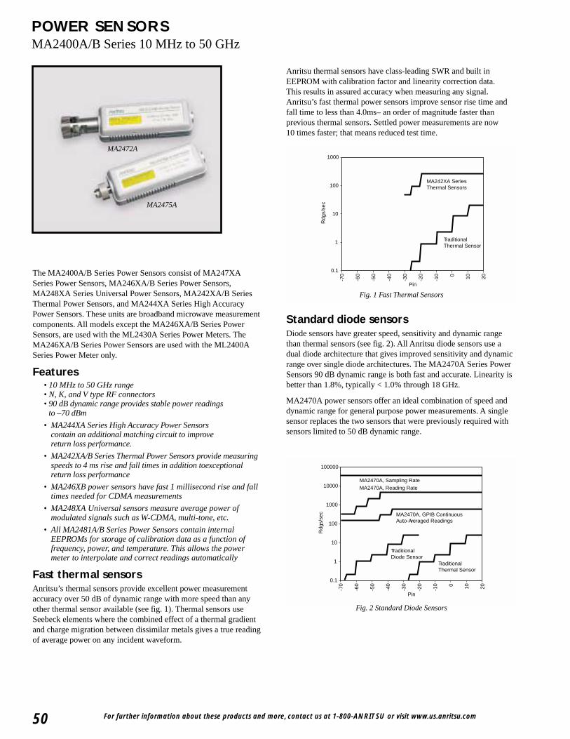
For further information about these products and more, contact us at 1-800-ANRITSU or visit www.us.anritsu.com50
POWER SENSORSMA2400A/B Series 10 MHz to 50 GHz
Anritsu thermal sensors have class-leading SWR and built inEEPROM with calibration factor and linearity correction data.This results in assured accuracy when measuring any signal.Anritsu’s fast thermal power sensors improve sensor rise time andfall time to less than 4.0ms– an order of magnitude faster thanprevious thermal sensors. Settled power measurements are now10 times faster; that means reduced test time.
Standard diode sensorsDiode sensors have greater speed, sensitivity and dynamic rangethan thermal sensors (see fig. 2). All Anritsu diode sensors use adual diode architecture that gives improved sensitivity and dynamicrange over single diode architectures. The MA2470A Series PowerSensors 90 dB dynamic range is both fast and accurate. Linearity isbetter than 1.8%, typically < 1.0% through 18 GHz.
MA2470A power sensors offer an ideal combination of speed anddynamic range for general purpose power measurements. A singlesensor replaces the two sensors that were previously required withsensors limited to 50 dB dynamic range.
The MA2400A/B Series Power Sensors consist of MA247XASeries Power Sensors, MA246XA/B Series Power Sensors,MA248XA Series Universal Power Sensors, MA242XA/B SeriesThermal Power Sensors, and MA244XA Series High AccuracyPower Sensors. These units are broadband microwave measurementcomponents. All models except the MA246XA/B Series PowerSensors, are used with the ML2430A Series Power Meters. TheMA246XA/B Series Power Sensors are used with the ML2400ASeries Power Meter only.
Features• 10 MHz to 50 GHz range• N, K, and V type RF connectors• 90 dB dynamic range provides stable power readings
to –70 dBm
• MA244XA Series High Accuracy Power Sensorscontain an additional matching circuit to improvereturn loss performance.
• MA242XA/B Series Thermal Power Sensors provide measuringspeeds to 4 ms rise and fall times in addition toexceptionalreturn loss performance
• MA246XB power sensors have fast 1 millisecond rise and falltimes needed for CDMA measurements
• MA248XA Universal sensors measure average power ofmodulated signals such as W-CDMA, multi-tone, etc.
• All MA2481A/B Series Power Sensors contain internalEEPROMs for storage of calibration data as a function offrequency, power, and temperature. This allows the powermeter to interpolate and correct readings automatically
Fast thermal sensorsAnritsu’s thermal sensors provide excellent power measurementaccuracy over 50 dB of dynamic range with more speed than anyother thermal sensor available (see fig. 1). Thermal sensors useSeebeck elements where the combined effect of a thermal gradientand charge migration between dissimilar metals gives a true readingof average power on any incident waveform.
MA2472A
MA2475A
MA2470A, Sampling RateMA2470A, Reading Rate
MA2470A, GPIB ContinuousAuto-Averaged Readings
TraditionalDiode Sensor
TraditionalThermal Sensor
100000
10000
1000
100
10
1
0.1
-70
-60
-50
-40
-30
-20
-10 0 10 20
Rdg
s/se
c
Pin
Fig. 2 Standard Diode Sensors
Fig. 1 Fast Thermal Sensors
MA242XA SeriesThermal Sensors
TraditionalThermal Sensor
1000
100
10
1
0.1
-70
-60
-50
-40
-30
-20
-10 0 10 20
Rdg
s/se
c
Pin
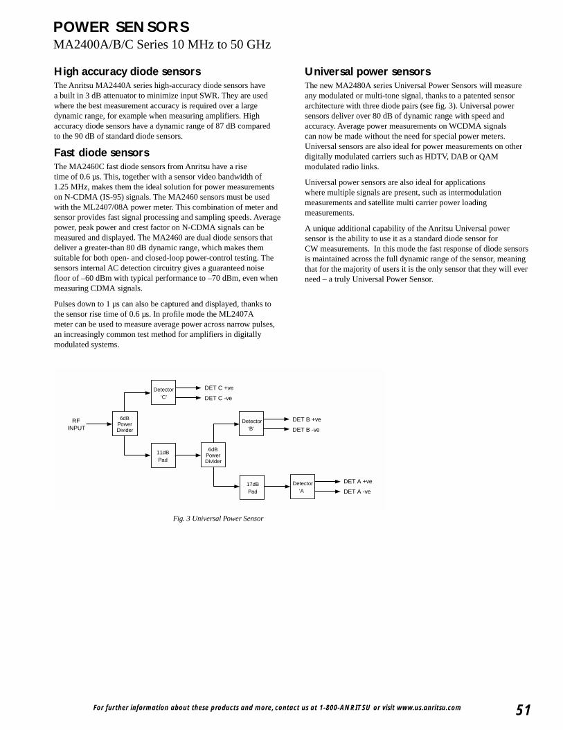
For further information about these products and more, contact us at 1-800-ANRITSU or visit www.us.anritsu.com 51
POWER SENSORSMA2400A/B/C Series 10 MHz to 50 GHz
Universal power sensorsThe new MA2480A series Universal Power Sensors will measureany modulated or multi-tone signal, thanks to a patented sensorarchitecture with three diode pairs (see fig. 3). Universal powersensors deliver over 80 dB of dynamic range with speed andaccuracy. Average power measurements on WCDMA signalscan now be made without the need for special power meters.Universal sensors are also ideal for power measurements on otherdigitally modulated carriers such as HDTV, DAB or QAMmodulated radio links.
Universal power sensors are also ideal for applicationswhere multiple signals are present, such as intermodulationmeasurements and satellite multi carrier power loadingmeasurements.
A unique additional capability of the Anritsu Universal powersensor is the ability to use it as a standard diode sensor forCW measurements. In this mode the fast response of diode sensorsis maintained across the full dynamic range of the sensor, meaningthat for the majority of users it is the only sensor that they will everneed – a truly Universal Power Sensor.
High accuracy diode sensorsThe Anritsu MA2440A series high-accuracy diode sensors havea built in 3 dB attenuator to minimize input SWR. They are usedwhere the best measurement accuracy is required over a largedynamic range, for example when measuring amplifiers. Highaccuracy diode sensors have a dynamic range of 87 dB comparedto the 90 dB of standard diode sensors.
Fast diode sensorsThe MA2460C fast diode sensors from Anritsu have a risetime of 0.6 µs. This, together with a sensor video bandwidth of1.25 MHz, makes them the ideal solution for power measurementson N-CDMA (IS-95) signals. The MA2460 sensors must be usedwith the ML2407/08A power meter. This combination of meter andsensor provides fast signal processing and sampling speeds. Averagepower, peak power and crest factor on N-CDMA signals can bemeasured and displayed. The MA2460 are dual diode sensors thatdeliver a greater-than 80 dB dynamic range, which makes themsuitable for both open- and closed-loop power-control testing. Thesensors internal AC detection circuitry gives a guaranteed noisefloor of –60 dBm with typical performance to –70 dBm, even whenmeasuring CDMA signals.
Pulses down to 1 µs can also be captured and displayed, thanks tothe sensor rise time of 0.6 µs. In profile mode the ML2407Ameter can be used to measure average power across narrow pulses,an increasingly common test method for amplifiers in digitallymodulated systems.
INPUT DET B -ve
DET B +ve
DET A -ve
DET A +ve
6dBPowerDivider
Detector‘C’
11dBPad
6dBPowerDivider
Detector‘B’
17dBPad
Detector‘A
DET C -ve
DET C +ve
RF
Fig. 3 Universal Power Sensor
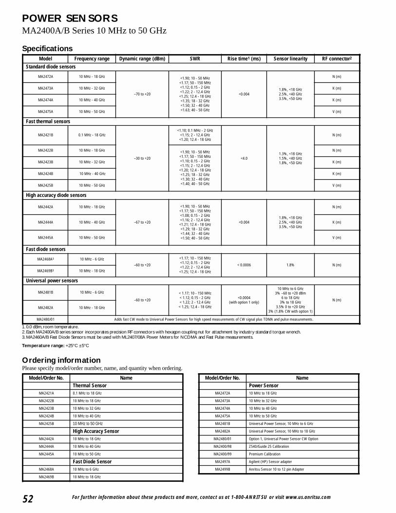
For further information about these products and more, contact us at 1-800-ANRITSU or visit www.us.anritsu.com52
POWER SENSORSMA2400A/B Series 10 MHz to 50 GHz
Specifications
1. 0.0 dBm, room temperature.2. Each MA2400A/B series sensor incorporates precision RF connectors with hexagon coupling nut for attachment by industry standard torque wrench.3. MA2460A/B Fast Diode Sensors must be used with ML2407/08A Power Meters for NCDMA and Fast Pulse measurements.
Temperature range: +25°C ±5°C
Ordering informationPlease specify model/order number, name, and quantity when ordering.
Model Frequency range Dynamic range (dBm) SWR Rise time1 (ms) Sensor linearity RF connector2
Standard diode sensors
MA2472A 10 MHz - 18 GHz
–70 to +20
<1.90; 10 - 50 MHz<1.17; 50 - 150 MHz<1.12; 0.15 - 2 GHz<1.22; 2 - 12.4 GHz<1.25; 12.4 - 18 GHz<1.35; 18 - 32 GHz<1.50; 32 - 40 GHz<1.63; 40 - 50 GHz
<0.0041.8%, <18 GHz2.5%, <40 GHz3.5%, <50 GHz
N (m)
MA2473A 10 MHz - 32 GHz K (m)
MA2474A 10 MHz - 40 GHz K (m)
MA2475A 10 MHz - 50 GHz V (m)
Fast thermal sensors
MA2421B 0.1 MHz - 18 GHz
–30 to +20
<1.10; 0.1 MHz - 2 GHz <1.15; 2 - 12.4 GHz <1.20; 12.4 - 18 GHz
<4.01.3%, <18 GHz1.5%, <40 GHz1.8%, <50 GHz
N (m)
MA2422B 10 MHz - 18 GHz <1.90; 10 - 50 MHz<1.17; 50 - 150 MHz<1.10; 0.15 - 2 GHz<1.15; 2 - 12.4 GHz<1.20; 12.4 - 18 GHz<1.25; 18 - 32 GHz<1.30; 32 - 40 GHz<1.40; 40 - 50 GHz
N (m)
MA2423B 10 MHz - 32 GHz K (m)
MA2424B 10 MHz - 40 GHz K (m)
MA2425B 10 MHz - 50 GHz V (m)
High accuracy diode sensors
MA2442A 10 MHz - 18 GHz
–67 to +20
<1.90; 10 - 50 MHz<1.17; 50 - 150 MHz<1.08; 0.15 - 2 GHz<1.16; 2 - 12.4 GHz<1.21; 12.4 - 18 GHz<1.29; 18 - 32 GHz<1.44; 32 - 40 GHz<1.50; 40 - 50 GHz
<0.0041.8%, <18 GHz2.5%, <40 GHz3.5%, <50 GHz
N (m)
MA2444A 10 MHz - 40 GHz K (m)
MA2445A 10 MHz - 50 GHz V (m)
Fast diode sensors
MA2468A3 10 MHz - 6 GHz–60 to +20
<1.17; 10 - 150 MHz<1.12; 0.15 - 2 GHz<1.22; 2 - 12.4 GHz<1.25; 12.4 - 18 GHz
< 0.0006 1.8% N (m)MA2469B3 10 MHz - 18 GHz
Universal power sensors
MA2481B 10 MHz - 6 GHz
–60 to +20
< 1.17; 10 - 150 MHz< 1.12; 0.15 - 2 GHz< 1.22; 2 - 12.4 GHz< 1.25; 12.4 - 18 GHz
<0.0004(with option 1 only)
10 MHz to 6 GHz3% –60 to +20 dBm
6 to 18 GHz3% to 18 GHz
3.5% 0 to +20 GHz3% (1.8% CW with option 1)
N (m)
MA2482A 10 MHz - 18 GHz
MA2480/01 Adds fast CW mode to Universal Power Sensors for high speed measurements of CW signal plus TDMA and pulse measurements.
Model/Order No. NameThermal Sensor
MA2421A 0.1 MHz to 18 GHz
MA2422B 10 MHz to 18 GHz
MA2423B 10 MHz to 32 GHz
MA2424B 10 MHz to 40 GHz
MA2425B 10 MHz to 50 GHz
High Accuracy SensorMA2442A 10 MHz to 18 GHz
MA2444A 10 MHz to 40 GHz
MA2445A 10 MHz to 50 GHz
Fast Diode SensorMA2468A 10 MHz to 6 GHz
MA2469B 10 MHz to 18 GHz
Model/Order No. NamePower Sensor
MA2472A 10 MHz to 18 GHz
MA2473A 10 MHz to 32 GHz
MA2474A 10 MHz to 40 GHz
MA2475A 10 MHz to 50 GHz
MA2481B Universal Power Sensor, 10 MHz to 6 GHz
MA2482A Universal Power Sensor, 10 MHz to 18 GHz
MA2480/01 Option 1, Universal Power Sensor CW Option
MA2400/98 Z540/Guide 25 Calibration
MA2400/99 Premium Calibration
MA2497A Agilent (HP) Sensor adapter
MA2499B Anritsu Sensor 10 to 12 pin Adapter
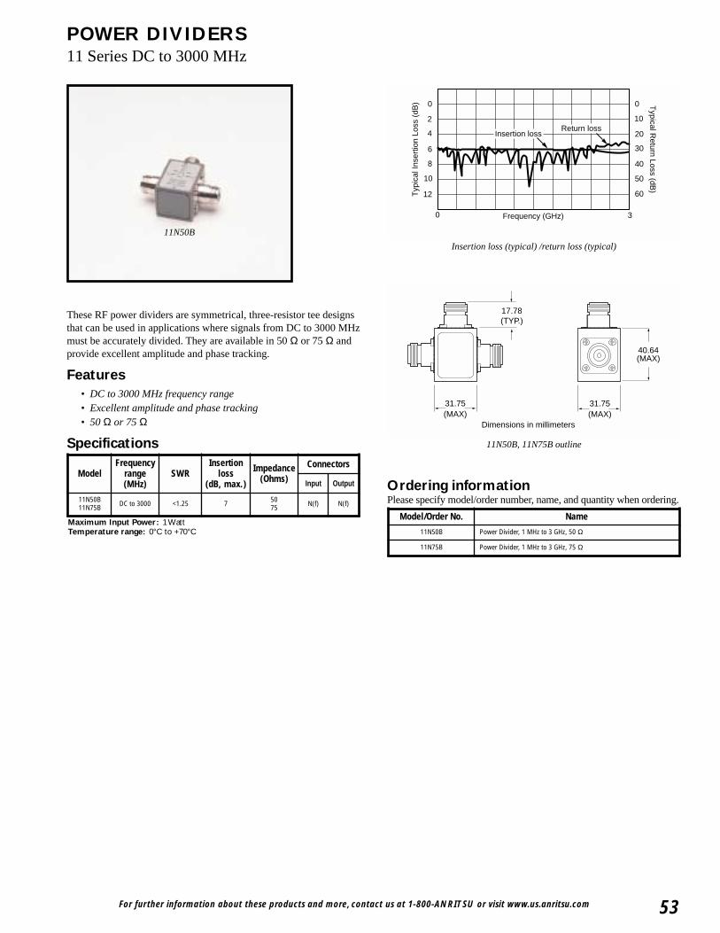
For further information about these products and more, contact us at 1-800-ANRITSU or visit www.us.anritsu.com 53
POWER DIVIDERS11 Series DC to 3000 MHz
These RF power dividers are symmetrical, three-resistor tee designsthat can be used in applications where signals from DC to 3000 MHzmust be accurately divided. They are available in 50 Ω or 75 Ω andprovide excellent amplitude and phase tracking.
Features• DC to 3000 MHz frequency range• Excellent amplitude and phase tracking• 50 Ω or 75 Ω
Specifications
Frequency (GHz)0 3
0
2
4
6
8
10
12
0
10
20
30
40
50
60
Typical R
eturn Loss (dB)
Typ
ical
Inse
rtio
n Lo
ss (
dB)
Return lossInsertion loss
11N50B
Insertion loss (typical) /return loss (typical)
31.75(MAX)
31.75(MAX)
40.64(MAX)
17.78(TYP.)
Dimensions in millimeters
11N50B, 11N75B outline
Ordering informationPlease specify model/order number, name, and quantity when ordering.
Maximum Input Power: 1 WattTemperature range: 0°C to +70°C
ModelFrequency
range(MHz)
SWRInsertion
loss(dB, max.)
Impedance(Ohms)
Connectors
Input Output
11N50B11N75B DC to 3000 <1.25 7 50
75 N(f) N(f)
Model/Order No. Name
11N50B Power Divider, 1 MHz to 3 GHz, 50 Ω
11N75B Power Divider, 1 MHz to 3 GHz, 75 Ω
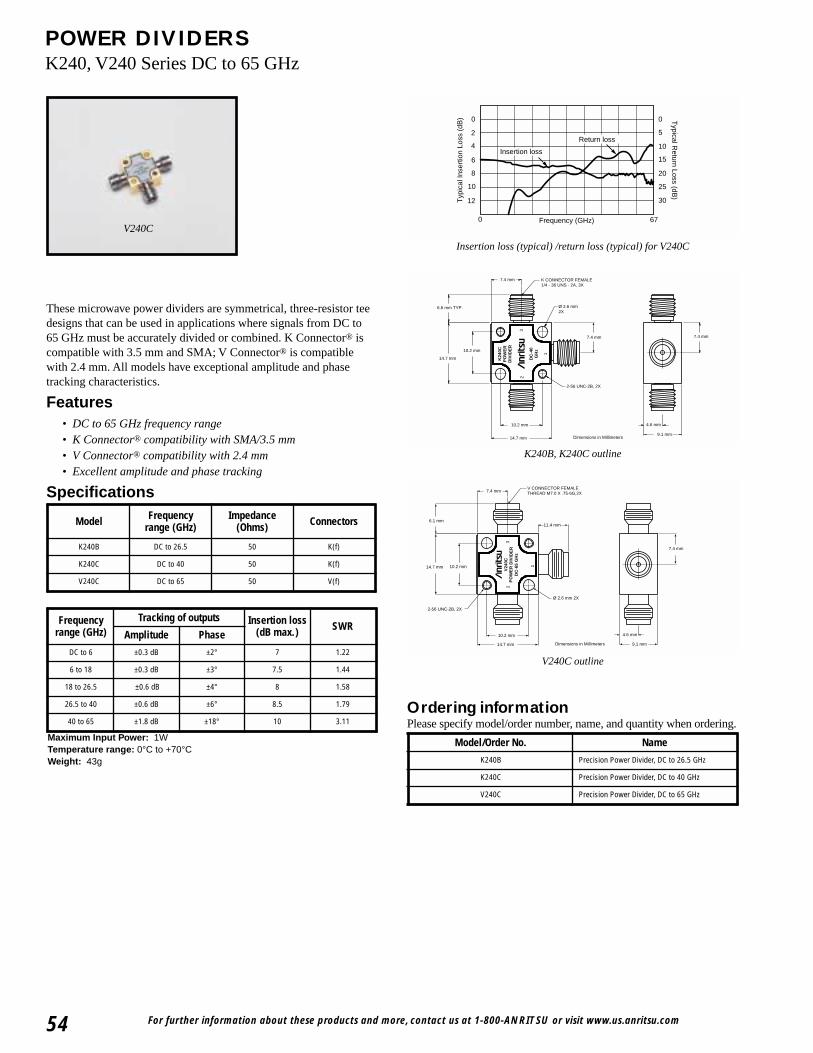
For further information about these products and more, contact us at 1-800-ANRITSU or visit www.us.anritsu.com54
POWER DIVIDERSK240, V240 Series DC to 65 GHz
Frequency (GHz)0 67
0
2
4
6
8
10
12
0
5
10
15
20
25
30
Typical R
eturn Loss (dB)
Typ
ical
Inse
rtio
n Lo
ss (
dB)
Return loss
Insertion loss
Insertion loss (typical) /return loss (typical) for V240C
7.4 mm
7.4 mm
1
2
3
14.7 mm
10.2 mm
14.7 mm
10.2 mm
Ø 2.6 mm 2X
2-56 UNC-2B, 2X
9.1 mm
4.6 mm
6.6 mm TYP.
7.4 mm
K CONNECTOR FEMALE1/4 - 36 UNS - 2A, 3X
K24
0CP
OW
ER
DIV
IDE
R
DC
-40
GH
z
Dimensions in Millimeters
K240B, K240C outline
4.6 mm
9.1 mm
2-56 UNC-2B, 2X
Ø 2.6 mm 2X
11.4 mm6.1 mm
10.2 mm14.7 mm
10.2 mm
14.7 mm
DC
-65
GH
z
32
1
7.4 mm
7.4 mmV CONNECTOR FEMALETHREAD M7.0 X .75-6G,2X
V24
0CP
OW
ER
DIV
IDE
R
Dimensions in Millimeters
V240C outline
Ordering informationPlease specify model/order number, name, and quantity when ordering.
These microwave power dividers are symmetrical, three-resistor teedesigns that can be used in applications where signals from DC to65 GHz must be accurately divided or combined. K Connector® iscompatible with 3.5 mm and SMA; V Connector® is compatiblewith 2.4 mm. All models have exceptional amplitude and phasetracking characteristics.
Features• DC to 65 GHz frequency range• K Connector® compatibility with SMA/3.5 mm• V Connector® compatibility with 2.4 mm• Excellent amplitude and phase tracking
Specifications
V240C
Maximum Input Power: 1WTemperature range: 0°C to +70°CWeight: 43g
Model/Order No. Name
K240B Precision Power Divider, DC to 26.5 GHz
K240C Precision Power Divider, DC to 40 GHz
V240C Precision Power Divider, DC to 65 GHz
Model Frequency range (GHz)
Impedance(Ohms) Connectors
K240B DC to 26.5 50 K(f)
K240C DC to 40 50 K(f)
V240C DC to 65 50 V(f)
Frequencyrange (GHz)
Tracking of outputs Insertion loss(dB max.) SWR
Amplitude Phase
DC to 6 ±0.3 dB ±2° 7 1.22
6 to 18 ±0.3 dB ±3° 7.5 1.44
18 to 26.5 ±0.6 dB ±4° 8 1.58
26.5 to 40 ±0.6 dB ±6° 8.5 1.79
40 to 65 ±1.8 dB ±18° 10 3.11
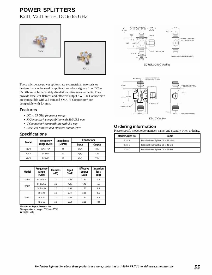
For further information about these products and more, contact us at 1-800-ANRITSU or visit www.us.anritsu.com 55
POWER SPLITTERSK241, V241 Series, DC to 65 GHz
K241C
V241C
OUTPUT
OUTPUT
INP
UT
6.1(TYP)
2.28
2.28
14.7
14.8(MAX)
10.16
10.16
11.5
(TYP)
K Female Connector1/4 - 36 UNS - 2A, 2X
K Male Connector1/2 - 36 UNS - 2B
2.64 2X
2-56 UNC-2B, 2X
4.57
9.2
Dimensions in millimeters
K241B, K241C Outline
4.6 mm
9.1 mm
2-56 UNC-2B, 2X
Ø 2.6 mm 2X
11.4 mm6.1 mm
10.2 mm14.7 mm
10.2 mm
14.7 mm
DC
-65G
Hz
PO
WE
R D
IVID
ER
V24
1CO
UT
OU
T
IN
7.4 mm
7.4 mm
V CONNECTOR MALETHREAD M7.0 X .75-6H
V CONNECTOR FEMALETHREAD M7.0 X .75-6G,2X
Dimensions in Millimeters
V241C Outline
These microwave power splitters are symmetrical, two-resistordesigns that can be used in applications where signals from DC to65 GHz must be accurately divided for ratio measurements. Theyprovide excellent flatness and effective output SWR. K Connectors®
are compatible with 3.5 mm and SMA; V Connectors® arecompatible with 2.4 mm.
Features• DC to 65 GHz frequency range• K Connector® compatibility with SMA/3.5 mm• V Connector® compatibility with 2.4 mm• Excellent flatness and effective output SWR
Specifications
Ordering informationPlease specify model/order number, name, and quantity when ordering.
Maximum Input Power: 1WTemperature range: 0°C to +70°CWeight: 43g
Model/Order No. Name
K241B Precision Power Splitter, DC to 26.5 GHz
K241C Precision Power Splitter, DC to 40 GHz
V241C Precision Power Splitter, DC to 65 GHz
Model Frequencyrange (GHz)
Impedance(Ohms)
Connectors
Input Output
K241B DC to 26.5 50 K(m) K(f)
K241C DC to 40 50 K(m) K(f)
V241C DC to 65 50 V(m) V(f)
ModelFrequency
range(GHz)
Flatness(dB)
InputSWR
EffectiveoutputSWR
Insertionloss(dB)
K241B DC to 26.5 2.0 1.45 1.45 7.5
K241CDC to 26.5 2.0 1.45 1.45 7.5
26.5 to 40 2.0 1.93 1.70 8.5
V241C
DC to 18 2.0 2.11 2.00 8.5
18 to 40 2.0 2.33 2.30 9.5
40 to 65 2.0 2.62 2.60 10.5
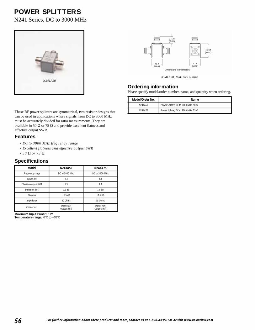
For further information about these products and more, contact us at 1-800-ANRITSU or visit www.us.anritsu.com56
POWER SPLITTERSN241 Series, DC to 3000 MHz
These RF power splitters are symmetrical, two resistor designs thatcan be used in applications where signals from DC to 3000 MHzmust be accurately divided for ratio measurements. They areavailable in 50 Ω or 75 Ω and provide excellent flatness andeffective output SWR.
Features• DC to 3000 MHz frequency range• Excellent flatness and effective output SWR• 50 Ω or 75 Ω
Specifications
31.8(MAX)
31.8(MAX)
40.64(MAX)
17.78(TYP.)
Dimensions in millimeters
Ordering informationPlease specify model/order number, name, and quantity when ordering.
N241A50, N241A75 outlineN241A50
Maximum Input Power: 1 WTemperature range: 0°C to +70°C
Model/Order No. Name
N241A50 Power Splitter, DC to 3000 MHz, 50 Ω
N241A75 Power Splitter, DC to 3000 MHz, 75 Ω
Model N241A50 N241A75
Frequency range DC to 3000 MHz DC to 3000 MHz
Input SWR 1.3 1.4
Effective output SWR 1.3 1.4
Insertion loss 7.5 dB 7.5 dB
Flatness ±1.5 dB ±1.5 dB
Impedance 50 Ohms 75 Ohms
Connectors Input: N(f)Output: N(f)
Input: N(f)Output: N(f)
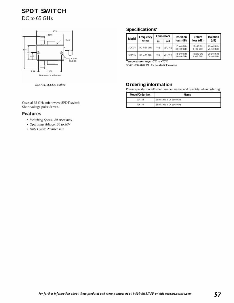
For further information about these products and more, contact us at 1-800-ANRITSU or visit www.us.anritsu.com 57
SPDT SWITCHDC to 65 GHz
45.5
33.90
40.6
17.8
8.88
28.702.54
BIAS
2 X 4-40UNC-2B
Dimensions in millimeters
SC4734, SC6135 outline
Coaxial 65 GHz microwave SPDT switchShort voltage pulse driven.
Features• Switching Speed: 20 msec max• Operating Voltage: 20 to 30V• Duty Cycle: 20 msec min
Ordering informationPlease specify model/order number, name, and quantity when ordering.
Temperature range: 0°C to +70°C*Call 1-800-ANRITSU for detailed information
Specifications*
Model Frequencyrange
Connectors Insertionloss (dB)
Returnloss (dB)
Isolation(dB)in out
SC4734 DC to 60 GHz V(f) V(f), V(f) 1.5 ≤40 GHz3.0 >40 GHz
10 ≤40 GHz6 >40 GHz
29 ≤40 GHz26 >40 GHz
SC6135 DC to 65 GHz V(f) V(f), V(f) 1.5 ≤40 GHz3.0 >40 GHz
10 ≤40 GHz6 >40 GHz
29 ≤40 GHz26 >40 GHz
Model/Order No. Name
SC4734 SPDT Switch, DC to 60 GHz
SC6135 SPDT Switch, DC to 65 GHz

For further information about these products and more, contact us at 1-800-ANRITSU or visit www.us.anritsu.com58
BIAS TEEK250 100 MHz to 40 GHz, V250 100 MHz to 60 GHz
These bias tees are designed for applications where both DC and RFsignals must be applied to a device under test. They are particularlysuited for active device measurements. DC voltages of up to 30 voltsat 0.5 amps may be applied to test devices with negligible effect onRF performance. Low RF throughline loss (<1 dB) and low returnloss ensure negligible effect on measurements up to 60 GHz. An RFinput DC block isolates the input port from the applied bias voltage.
Features• Broadband, 0.1 to 60 GHz coverage• Low SWR, low insertion loss• K Connector® and V Connector® availability
Specifications
DIMENSIONS IN MILLIMETERS
6.35 NOM
Ø 2.69 THRU
12.7 NOM
6.35 NOM
12.7 NOM 2.54 NOM
7.87 NOM
29.2 NOM
6.35 NOM
OUT
BIAS TEE K250 DCIN
RF IN
SMC MALE CONNECTOR
K FEMALE.25-36 UNS-2A
K MALE.25-36 UNS-2B
Outline drawing (K and V models)
DC IN
RF OUTRFIN
Schematic diagram (K and V models)
Ordering informationPlease specify model/order number, name, and quantity when ordering.
Specifications
K250
1. Usable between 0.04 and 0.1 GHz with degraded performance.Temperature range: 0°C to +70°C
Model K250 V250
Frequency range 0.1 to 40 GHz1 0.1 to 60 GHz1
Insertion loss 1.2 dB typ. 2.2 dB typ.
Return loss 15 dB min. to 20 GHz10 dB min. to 40 GHz
13 dB min. to 20 GHz9 dB min. to 40 GHz8 dB min. to 60 GHz
RF power 1W max. 1W max.
DC voltage 30V max. 30V max.
DC current 0.5A 0.5A
DC port isolation 20 dB at 0.1 GHz40 dB above 0.5 GHz
20 dB at 0.1 GHz40 dB above 0.5 GHz
RF connectors Input: K(m)Output: K(f)
Input: V(m)Output: V(f)
DC connectors SMC(m) SMC(m)
Model/Order No. Name
K250 Precision Bias Tee, 100 MHz to 40 GHz
V250 Precision Bias Tee, 100 MHz to 60 GHz
Temperature 0 to 60°C
Mounting position Any
Weight 57g

For further information about these products and more, contact us at 1-800-ANRITSU or visit www.us.anritsu.com 59
ULTRA-WIDEBAND BIAS TEESK251 50 kHz to 40 GHz, V251 100 kHz to 65 GHz
These ultra-wide bandwidth bias tees have been optimized foroptical communications and other high-speed pulse, data ormicrowave applications. Designed to simultaneously apply bothDC and RF drive signals to a device via a single input port, thesebias tees feature fast rise times, excellent low frequency response,minimum insertion loss and flat group delay. PrecisionK Connector® and V Connector® interfaces assure excellentimpedance match across the wide bandwidths available. A one yearwarranty is provided. Adapters are available to convert betweenK and V Connectors - See page 21 of this catalog for details.
Features• Ideal for Optical Communications Applications• Low Insertion Loss• Risetime: <5 ps typical (V251), <7 ps typical (K251)
Specifications
Specifications apply over the full DC Bias current range and over the temperature range of 0°C to +70°C.
4.45
1/4-36 UNS-2B
1/4-36 UNS-2A
2.03
2.03TYP
TYP
7.72
2X Ø.104 THRU
15.44
39.5
31.8 (MAX)
8.89
4.45
7.1
11.8
K251 BIAS TEE
RF IN
OUT
DCIN
S/N XXXXXX
33.4
SMC MALE CONNECTOR
K MALE CONNECTOR
MOUNTING HOLE
K FEMALE CONNECTOR
Dimensions in millimeters
33.7
4.45
M7.0 X .75-6H
M7.0 X .75-6G
2.03
2.03TYP
TYP
7.72
2X Ø.104 THRU
15.44
39.531.75
8.89
4.45
7.11
11.0
V251 BIAS TEE
RF IN
OUT
DCIN
S/N XXXXXX
SMC MALE CONNECTOR
V MALE CONNECTOR
MOUNTING HOLE
V FEMALE CONNECTOR
Dimensions in millimeters
K251 outline drawing
V251 outline drawing
K251
V251
ModelFrequency
range3dB BW
Insertion loss Return loss Rise time Group delay Max DC current
Max DC voltage
MaxRF power Connectors
K251 50 kHz to40 GHz <2 dB typical See Plot < 7 ps typical 110 ± 2 ps
typical 100 mA 16VDC 1 WRF In: K(m)RF Out: K(f)
Bias: SMC(m)
V251 100 kHz to65 GHz < 2.5 dB typical See Plot < 5 ps typical 113 ± 2 ps
typical 100 mA 16VDC 1 WRF In: V(m)RF Out: V(f)
Bias: SMC(m)
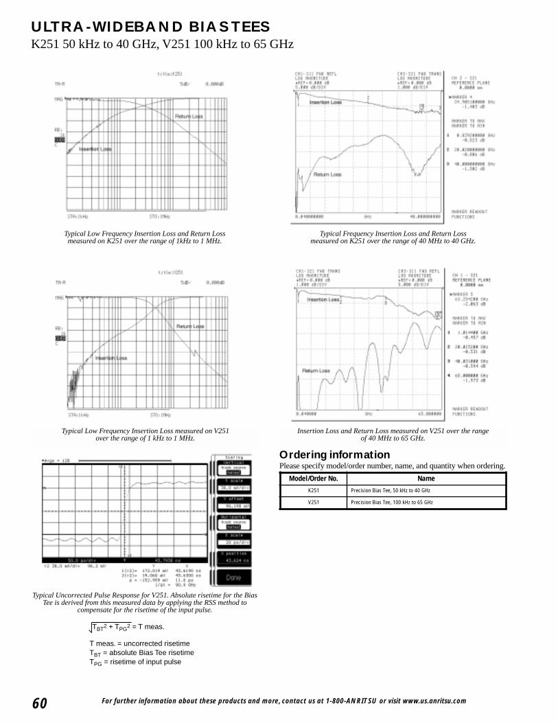
For further information about these products and more, contact us at 1-800-ANRITSU or visit www.us.anritsu.com60
ULTRA-WIDEBAND BIAS TEESK251 50 kHz to 40 GHz, V251 100 kHz to 65 GHz
Ordering informationPlease specify model/order number, name, and quantity when ordering.
Typical Low Frequency Insertion Loss measured on V251 over the range of 1 kHz to 1 MHz.
Insertion Loss and Return Loss measured on V251 over the range of 40 MHz to 65 GHz.
Typical Uncorrected Pulse Response for V251. Absolute risetime for the BiasTee is derived from this measured data by applying the RSS method to
compensate for the risetime of the input pulse.
T meas. = uncorrected risetimeTBT = absolute Bias Tee risetimeTPG = risetime of input pulse
TBT2 + TPG2 = T meas.
Typical Low Frequency Insertion Loss and Return Loss measured on K251 over the range of 1kHz to 1 MHz.
Typical Frequency Insertion Loss and Return Loss measured on K251 over the range of 40 MHz to 40 GHz.
Model/Order No. Name
K251 Precision Bias Tee, 50 kHz to 40 GHz
V251 Precision Bias Tee, 100 kHz to 65 GHz

For further information about these products and more, contact us at 1-800-ANRITSU or visit www.us.anritsu.com 61
ULTRA-WIDEBAND BIAS TEESV255 50 kHz to 65 GHz
S/N 110020V255 BIAS TEE
RF OUT
RF IN
DCIN
7.1
21.3
39.6
2.0
2.8
2.8
6.5
52.8
61.7
6.5 7.0
14.0
10.7
V-MALE CONNECTORM7.0 X 75-6H
V-FEMALE CONNECTORM7.0 X 75-6G
2X MOUNTING HOLE∅ 2.5[.10] THRU
SMC MALE CONNECTOR
V255 outline drawing
K255
The V255 Gen II Ultra Wideband Bias Tee is designed to meet thehigh electrical performance requirement of passive components inoptical communication networks. Given a broader bandwidth of50 kHz to 65 GHz, with low insertion losses and very good returnloss, makes it ideal to use in 40 Gbps systems to bias opticalmodulators and broad band data drivers. It's fast rise time and flatgroup delay performance allows extremely accurate measurementswithin a laboratory environment. The V255 Bias Tee comes with astandard V Connector® that assures excellent impedance matchacross the available wide bandwidth. The DC signal can beapplied or extracted from the bias tee through an SMC connectorat the third port. As with our other bias tees, the V255 also has aone-year warranty.
Specifications
Features• Ideal for Optical Communication applications.
• Very low Insertion Loss• Rise Time 3 ps typical • High Current Capacity• High Isolation between Input Port and DC Port
Model Frequencyrange Insertion loss Return loss Rise time Group delay Max
DC currentMax
DC voltageMin.
IsolationOperating
temperature
V25550 kHz to 65 GHz30 kHz to 65 GHz
typical
1.2 dB to 65 GHztypical
<–15 dB to 65 GHztypical 3 ps typical 125 ± 2 ps typical 400 mA 16 VDC –50 dBm 0˚C to 80˚C
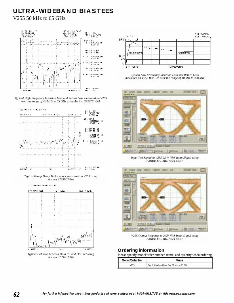
For further information about these products and more, contact us at 1-800-ANRITSU or visit www.us.anritsu.com62
ULTRA-WIDEBAND BIAS TEESV255 50 kHz to 65 GHz
Typical Group Delay Performance measured on V255 using Anritsu 37397C VNA
Typical High Frequency Insertion Loss and Return Loss measured on V255over the range of 40 MHz to 65 GHz using Anritsu 37397C VNA
Typical Isolation between Data I/P and DC Port using Anritsu 37397C VNA
Typical Low Frequency Insertion Loss and Return Loss measured on V255 Bias Tee over the range of 10 kHz to 300 kHz
Ordering informationPlease specify model/order number, name, and quantity when ordering.
Model/Order No. Name
V255 Gen II Wideband Bias Tee, 50 kHz to 65 GHz
Input Test Signal to V255 2.0 V NRZ Input Signal using Anritsu 43G ME7750A BERT
V255 Output Response to 2.0V NRZ Input Signal using Anritsu 43G ME7750A BERT
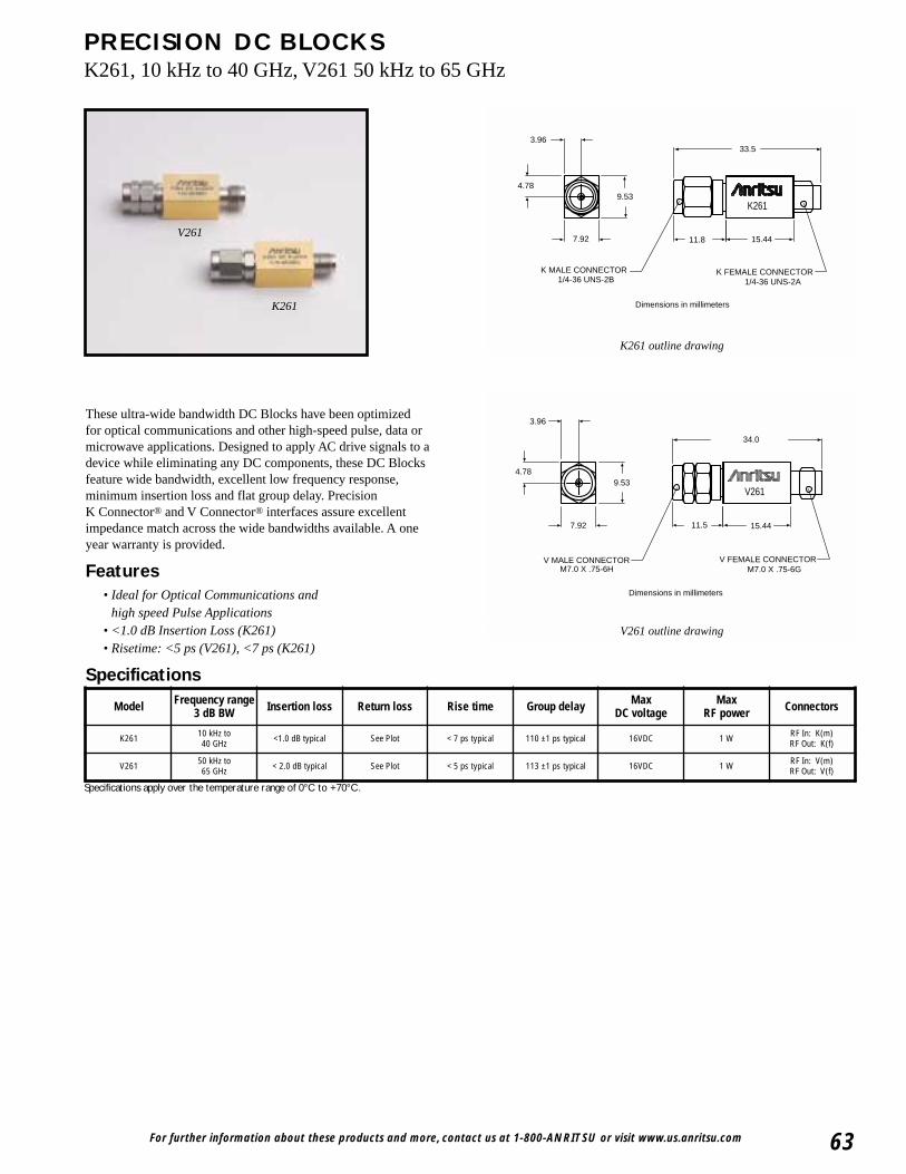
For further information about these products and more, contact us at 1-800-ANRITSU or visit www.us.anritsu.com 63
PRECISION DC BLOCKSK261, 10 kHz to 40 GHz, V261 50 kHz to 65 GHz
3.96
15.44
9.534.78
7.92
K261
1/4-36 UNS-2B 1/4-36 UNS-2A
11.8
33.5
K MALE CONNECTOR K FEMALE CONNECTOR
Dimensions in millimeters
3.96
34.0
15.4411.5
9.534.78
7.92
V261
M7.0 X .75-6H M7.0 X .75-6GV MALE CONNECTOR V FEMALE CONNECTOR
Dimensions in millimeters
K261 outline drawing
V261 outline drawing
These ultra-wide bandwidth DC Blocks have been optimizedfor optical communications and other high-speed pulse, data ormicrowave applications. Designed to apply AC drive signals to adevice while eliminating any DC components, these DC Blocksfeature wide bandwidth, excellent low frequency response,minimum insertion loss and flat group delay. PrecisionK Connector® and V Connector® interfaces assure excellentimpedance match across the wide bandwidths available. A oneyear warranty is provided.
Features• Ideal for Optical Communications and
high speed Pulse Applications• <1.0 dB Insertion Loss (K261)• Risetime: <5 ps (V261), <7 ps (K261)
Specifications
V261
K261
Specifications apply over the temperature range of 0°C to +70°C.
Model Frequency range 3 dB BW Insertion loss Return loss Rise time Group delay Max
DC voltageMax
RF power Connectors
K261 10 kHz to40 GHz <1.0 dB typical See Plot < 7 ps typical 110 ±1 ps typical 16VDC 1 W RF In: K(m)
RF Out: K(f)
V261 50 kHz to65 GHz < 2.0 dB typical See Plot < 5 ps typical 113 ±1 ps typical 16VDC 1 W RF In: V(m)
RF Out: V(f)

For further information about these products and more, contact us at 1-800-ANRITSU or visit www.us.anritsu.com64
PRECISION DC BLOCKSK261, 10 kHz to 40 GHz, V261 50 kHz to 65 GHz
Typical Low Frequency Insertion Loss measured on V261 over the range of 1 kHz to 1 MHz.
Insertion Loss and Return Loss measured on V261 over the range of 40 MHz to 65 GHz.
Typical Uncorrected Pulse Response for V261. Absolute risetime for the DCBlocks is derived from this measured data by applying the RSS method to
compensate for the risetime of the input pulse.
T meas. = uncorrected risetimeTBT = absolute Bias Tee risetimeTPG = risetime of input pulse
TBT2 + TPG2 = T meas.
Ordering informationPlease specify model/order number, name, and quantity when ordering.
Typical Low Frequency Insertion Loss measured on K261 over the range of 1 kHz to 1 MHz. Insertion Loss and Return Loss measured on K261 over the range
of 40 MHz to 40 GHz.
Model/Order No. Name
K261 Precision DC Block, 50 kHz to 40 GHz
V261 Precision DC Block, 100 kHz to 65 GHz
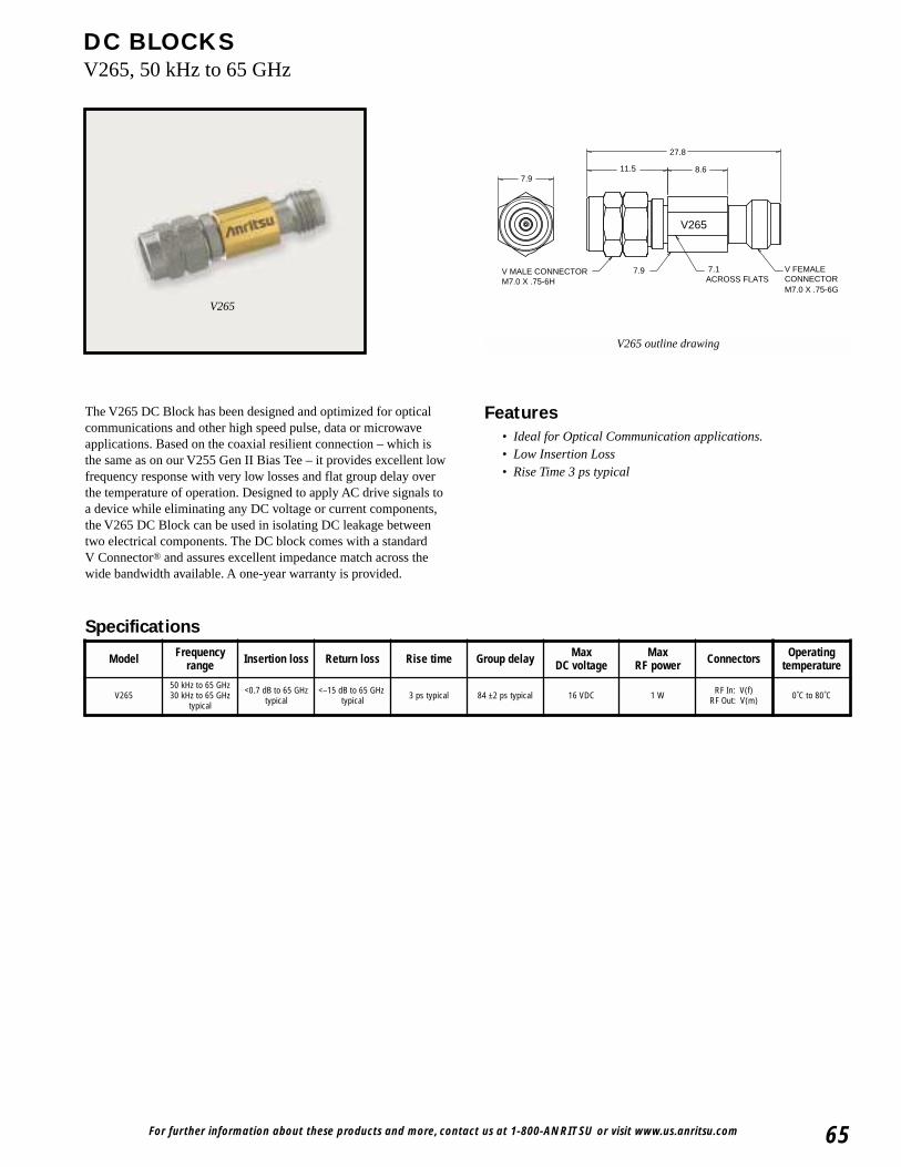
For further information about these products and more, contact us at 1-800-ANRITSU or visit www.us.anritsu.com 65
DC BLOCKSV265, 50 kHz to 65 GHz
V265 outline drawing
The V265 DC Block has been designed and optimized for opticalcommunications and other high speed pulse, data or microwaveapplications. Based on the coaxial resilient connection – which isthe same as on our V255 Gen II Bias Tee – it provides excellent lowfrequency response with very low losses and flat group delay overthe temperature of operation. Designed to apply AC drive signals toa device while eliminating any DC voltage or current components,the V265 DC Block can be used in isolating DC leakage betweentwo electrical components. The DC block comes with a standardV Connector® and assures excellent impedance match across thewide bandwidth available. A one-year warranty is provided.
Specifications
Features• Ideal for Optical Communication applications.• Low Insertion Loss• Rise Time 3 ps typical
V265
Model Frequencyrange Insertion loss Return loss Rise time Group delay Max
DC voltageMax
RF power Connectors Operatingtemperature
V26550 kHz to 65 GHz30 kHz to 65 GHz
typical
<0.7 dB to 65 GHztypical
<–15 dB to 65 GHz typical 3 ps typical 84 ±2 ps typical 16 VDC 1 W RF In: V(f)
RF Out: V(m) 0˚C to 80˚C
V265
11.5 8.6
27.8
V MALE CONNECTORM7.0 X .75-6H
V FEMALE CONNECTORM7.0 X .75-6G
7.1ACROSS FLATS
7.9
7.9
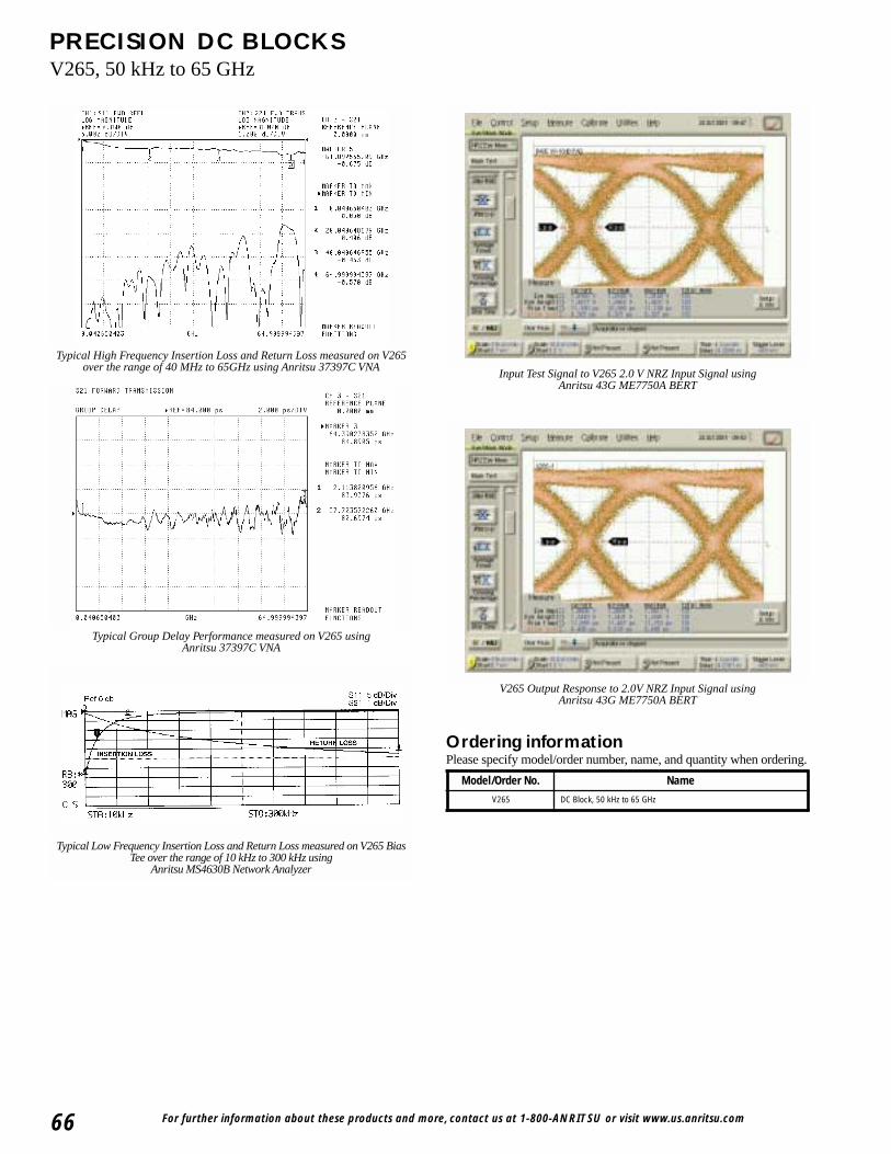
For further information about these products and more, contact us at 1-800-ANRITSU or visit www.us.anritsu.com66
PRECISION DC BLOCKSV265, 50 kHz to 65 GHz
Typical Low Frequency Insertion Loss and Return Loss measured on V265 BiasTee over the range of 10 kHz to 300 kHz using
Anritsu MS4630B Network Analyzer
Ordering informationPlease specify model/order number, name, and quantity when ordering.
Typical High Frequency Insertion Loss and Return Loss measured on V265over the range of 40 MHz to 65GHz using Anritsu 37397C VNA
Typical Group Delay Performance measured on V265 using Anritsu 37397C VNA
Input Test Signal to V265 2.0 V NRZ Input Signal using Anritsu 43G ME7750A BERT
V265 Output Response to 2.0V NRZ Input Signal using Anritsu 43G ME7750A BERT
Model/Order No. Name
V265 DC Block, 50 kHz to 65 GHz
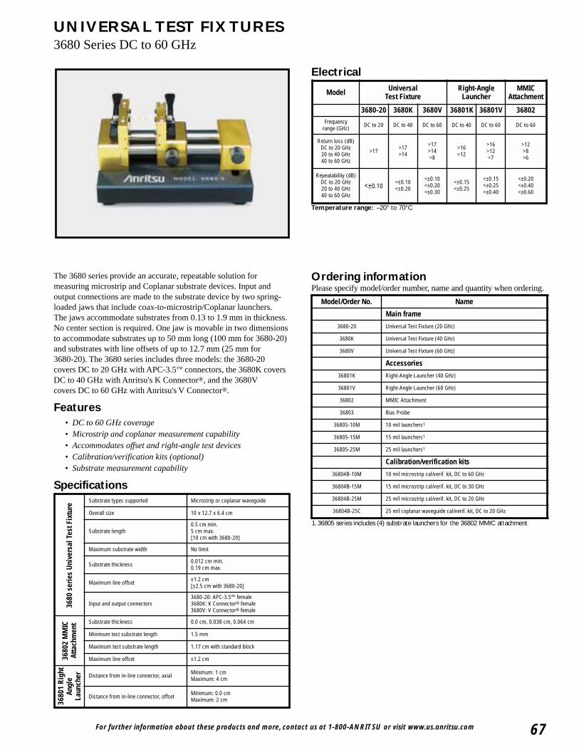
For further information about these products and more, contact us at 1-800-ANRITSU or visit www.us.anritsu.com 67
UNIVERSAL TEST FIXTURES3680 Series DC to 60 GHz
The 3680 series provide an accurate, repeatable solution formeasuring microstrip and Coplanar substrate devices. Input andoutput connections are made to the substrate device by two spring-loaded jaws that include coax-to-microstrip/Coplanar launchers.The jaws accommodate substrates from 0.13 to 1.9 mm in thickness.No center section is required. One jaw is movable in two dimensionsto accommodate substrates up to 50 mm long (100 mm for 3680-20)and substrates with line offsets of up to 12.7 mm (25 mm for 3680-20). The 3680 series includes three models: the 3680-20covers DC to 20 GHz with APC-3.5™ connectors, the 3680K coversDC to 40 GHz with Anritsu's K Connector®, and the 3680Vcovers DC to 60 GHz with Anritsu's V Connector®.
Features• DC to 60 GHz coverage• Microstrip and coplanar measurement capability• Accommodates offset and right-angle test devices• Calibration/verification kits (optional)• Substrate measurement capability
Specifications
Electrical
Ordering informationPlease specify model/order number, name and quantity when ordering.
1. 36805 series includes (4) substrate launchers for the 36802 MMIC attachment
Temperature range: –20° to 70°C
3680
ser
ies
Univ
ersa
l Tes
t Fix
ture
Substrate types supported Microstrip or coplanar waveguide
Overall size 10 x 12.7 x 6.4 cm
Substrate length0.5 cm min.5 cm max.[10 cm with 3680-20]
Maximum substrate width No limit
Substrate thickness 0.012 cm min.0.19 cm max.
Maximum line offset ±1.2 cm[±2.5 cm with 3680-20]
Input and output connectors3680-20: APC-3.5™ female3680K: K Connector® female3680V: V Connector® female
3680
2 M
MIC
Atta
chm
ent Substrate thickness 0.0 cm, 0.038 cm, 0.064 cm
Minimum test substrate length 1.5 mm
Maximum test substrate length 1.17 cm with standard block
Maximum line offset ±1.2 cm
3680
1 Ri
ght
Angl
eLa
unch
er Distance from in-line connector, axial Minimum: 1 cm Maximum: 4 cm
Distance from in-line connector, offset Minimum: 0.0 cmMaximum: 2 cm
Model Universal Test Fixture
Right-AngleLauncher
MMICAttachment
3680-20 3680K 3680V 36801K 36801V 36802Frequency
range (GHz) DC to 20 DC to 40 DC to 60 DC to 40 DC to 60 DC to 60
Return loss (dB)DC to 20 GHz20 to 40 GHz40 to 60 GHz
>17 >17>14
>17>14>8
>16>12
>16>12>7
>12>8>6
Repeatability (dB)DC to 20 GHz20 to 40 GHz40 to 60 GHz
<±0.10<±0.10<±0.20
<±0.10<±0.20<±0.30
<±0.15<±0.25
<±0.15<±0.25<±0.40
<±0.20<±0.40<±0.60
Model/Order No. Name
Main frame
3680-20 Universal Test Fixture (20 GHz)
3680K Universal Test Fixture (40 GHz)
3680V Universal Test Fixture (60 GHz)
Accessories
36801K Right-Angle Launcher (40 GHz)
36801V Right-Angle Launcher (60 GHz)
36802 MMIC Attachment
36803 Bias Probe
36805-10M 10 mil launchers1
36805-15M 15 mil launchers1
36805-25M 25 mil launchers1
Calibration/verification kits
36804B-10M 10 mil microstrip cal/verif. kit, DC to 60 GHz
36804B-15M 15 mil microstrip cal/verif. kit, DC to 30 GHz
36804B-25M 25 mil microstrip cal/verif. kit, DC to 20 GHz
36804B-25C 25 mil coplanar waveguide cal/verif. kit, DC to 20 GHz
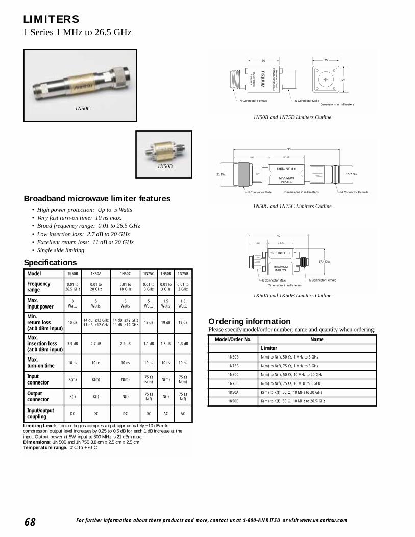
For further information about these products and more, contact us at 1-800-ANRITSU or visit www.us.anritsu.com68
LIMITERS1 Series 1 MHz to 26.5 GHz
Broadband microwave limiter features• High power protection: Up to 5 Watts• Very fast turn-on time: 10 ns max.• Broad frequency range: 0.01 to 26.5 GHz• Low insertion loss: 2.7 dB to 20 GHz• Excellent return loss: 11 dB at 20 GHz• Single side limiting
Specifications
1N50C
1K50B
Dimensions in millimeters
30 25
25
N Connector MaleN Connector Female
LIM
ITE
RS
MO
DE
L 1N
75B
FR
EQ
UE
NC
Y R
AN
GE
1MH
z -
3000
MH
z
MAXIMUMINPUTS
RF LIMITERS
N Connector Male N Connector Female
95
32.313
21 Dia. 15.7 Dia.
Dimensions in millimeters
MAXIMUMINPUTS
RF LIMITERS
17.413
40
17.4 Dia.
K Connector Male K Connector Female
Dimensions in millimeters
1N50C and 1N75C Limiters Outline
1K50A and 1K50B Limiters Outline
1N50B and 1N75B Limiters Outline
Limiting Level: Limiter begins compressing at approximately +10 dBm. In compression, output level increases by 0.25 to 0.5 dB for each 1 dB increase at theinput. Output power at 5W input at 500 MHz is 21 dBm max.Dimensions: 1N50B and 1N75B 3.8 cm x 2.5 cm x 2.5 cmTemperature range: 0°C to +70°C
Ordering informationPlease specify model/order number, name and quantity when ordering.
Model/Order No. Name
Limiter
1N50B N(m) to N(f), 50 Ω, 1 MHz to 3 GHz
1N75B N(m) to N(f), 75 Ω, 1 MHz to 3 GHz
1N50C N(m) to N(f), 50 Ω, 10 MHz to 20 GHz
1N75C N(m) to N(f), 75 Ω, 10 MHz to 3 GHz
1K50A K(m) to K(f), 50 Ω, 10 MHz to 20 GHz
1K50B K(m) to K(f), 50 Ω, 10 MHz to 26.5 GHz
Model 1K50B 1K50A 1N50C 1N75C 1N50B 1N75B
Frequency range
0.01 to26.5 GHz
0.01 to 20 GHz
0.01 to 18 GHz
0.01 to 3 GHz
0.01 to 3 GHz
0.01 to 3 GHz
Max. input power
3 Watts
5 Watts
5 Watts
5 Watts
1.5Watts
1.5Watts
Min. return loss (at 0 dBm input)
10 dB 14 dB, ≤12 GHz11 dB, >12 GHz
14 dB, ≤12 GHz11 dB, >12 GHz 15 dB 19 dB 19 dB
Max.insertion loss(at 0 dBm input)
3.9 dB 2.7 dB 2.9 dB 1.1 dB 1.3 dB 1.3 dB
Max. turn-on time
10 ns 10 ns 10 ns 10 ns 10 ns 10 ns
Input connector
K(m) K(m) N(m) 75 ΩN(m) N(m) 75 Ω
N(m)
Output connector
K(f) K(f) N(f) 75 ΩN(f) N(f) 75 Ω
N(f)
Input/outputcoupling
DC DC DC DC AC AC

For further information about these products and more, contact us at 1-800-ANRITSU or visit www.us.anritsu.com 69
MATCHING PADS12 Series DC to 3000 MHz
Specifications
RF matching pad and impedance adapter features
• DC to 3000 MHz frequency range• Matching pad matches 50 Ω to 75 Ω or 75 Ω to 50 Ω circuits• Impedance adapter converts 50 Ω to 75 Ω with <3 dB loss
The 12N50-75B matching pad is a two-resistor design that matches50 Ω to 75 Ω or 75 Ω to 50 Ω circuits.
The 12N75B impedance adapter is a one-resistor design thatconverts 50 Ω to 75 Ω with less than 3 dB loss.
12N50-75B
Temperature range: 0°C to +70°CDimensions: 3.8 cm x 2.5 cm x 2.5 cm
Ordering informationPlease specify model/order number, name and quantity when ordering.
Model Frequencyrange (MHz) SWR Insertion loss
(dB) Connectors
12N50-75B DC to 3000 1.25 7.5 max. N(m) 50Ω to N(f) 75Ω
12N75B DC to 3000 1.25 3.0 max. N(m) 50Ω to N(m) 75Ω
Model/Order No. Name
12N50-75B Matching Pad, DC to 3000 MHz
12N75B Minimum Loss Adapter, DC to 3000 MHz
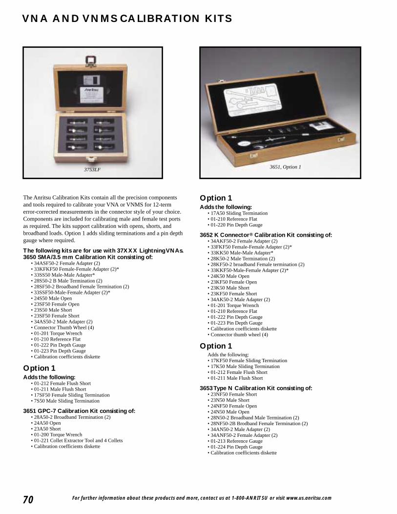
For further information about these products and more, contact us at 1-800-ANRITSU or visit www.us.anritsu.com70
VNA AND VNMS CALIBRATION KITS
3753LF 3651, Option 1
The Anritsu Calibration Kits contain all the precision componentsand tools required to calibrate your VNA or VNMS for 12-termerror-corrected measurements in the connector style of your choice.Components are included for calibrating male and female test portsas required. The kits support calibration with opens, shorts, andbroadband loads. Option 1 adds sliding terminations and a pin depthgauge where required.
The following kits are for use with 37XXX Lightning VNAs.3650 SMA/3.5 mm Calibration Kit consisting of:
• 34ASF50-2 Female Adapter (2)• 33KFKF50 Female-Female Adapter (2)*• 33SS50 Male-Male Adapter*• 28S50-2 B Male Termination (2)• 28SF50-2 Broadband Female Termination (2)• 33SSF50-Male-Female Adapter (2)*• 24S50 Male Open• 23SF50 Female Open• 23S50 Male Short• 23SF50 Female Short• 34AS50-2 Male Adapter (2)• Connector Thumb Wheel (4)• 01-201 Torque Wrench• 01-210 Reference Flat• 01-222 Pin Depth Gauge• 01-223 Pin Depth Gauge • Calibration coefficients diskette
Option 1Adds the following:
• 01-212 Female Flush Short • 01-211 Male Flush Short • 17SF50 Female Sliding Termination • 7S50 Male Sliding Termination
3651 GPC-7 Calibration Kit consisting of:• 28A50-2 Broadband Termination (2)• 24A50 Open• 23A50 Short• 01-200 Torque Wrench• 01-221 Collet Extractor Tool and 4 Collets• Calibration coefficients diskette
Option 1Adds the following:
• 17A50 Sliding Termination • 01-210 Reference Flat• 01-220 Pin Depth Gauge
3652 K Connector® Calibration Kit consisting of:• 34AKF50-2 Female Adapter (2)• 33FKF50 Female-Female Adapter (2)*• 33KK50 Male-Male Adapter*• 28K50-2 Male Termination (2)• 28KF50-2 broadband Female termination (2)• 33KKF50-Male-Female Adapter (2)*• 24K50 Male Open• 23KF50 Female Open• 23K50 Male Short• 23KF50 Female Short• 34AK50-2 Male Adapter (2)• 01-201 Torque Wrench• 01-210 Reference Flat• 01-222 Pin Depth Gauge• 01-223 Pin Depth Gauge• Calibration coefficients diskette• Connector thumb wheel (4)
Option 1Adds the following:• 17KF50 Female Sliding Termination • 17K50 Male Sliding Termination• 01-212 Female Flush Short • 01-211 Male Flush Short
3653 Type N Calibration Kit consisting of:• 23NF50 Female Short• 23N50 Male Short• 24NF50 Female Open• 24N50 Male Open• 28N50-2 Broadband Male Termination (2)• 28NF50-2B Brodband Female Termination (2)• 34AN50-2 Male Adapter (2)• 34ANF50-2 Female Adapter (2)• 01-213 Reference Gauge• 01-224 Pin Depth Gauge• Calibration coefficients diskette
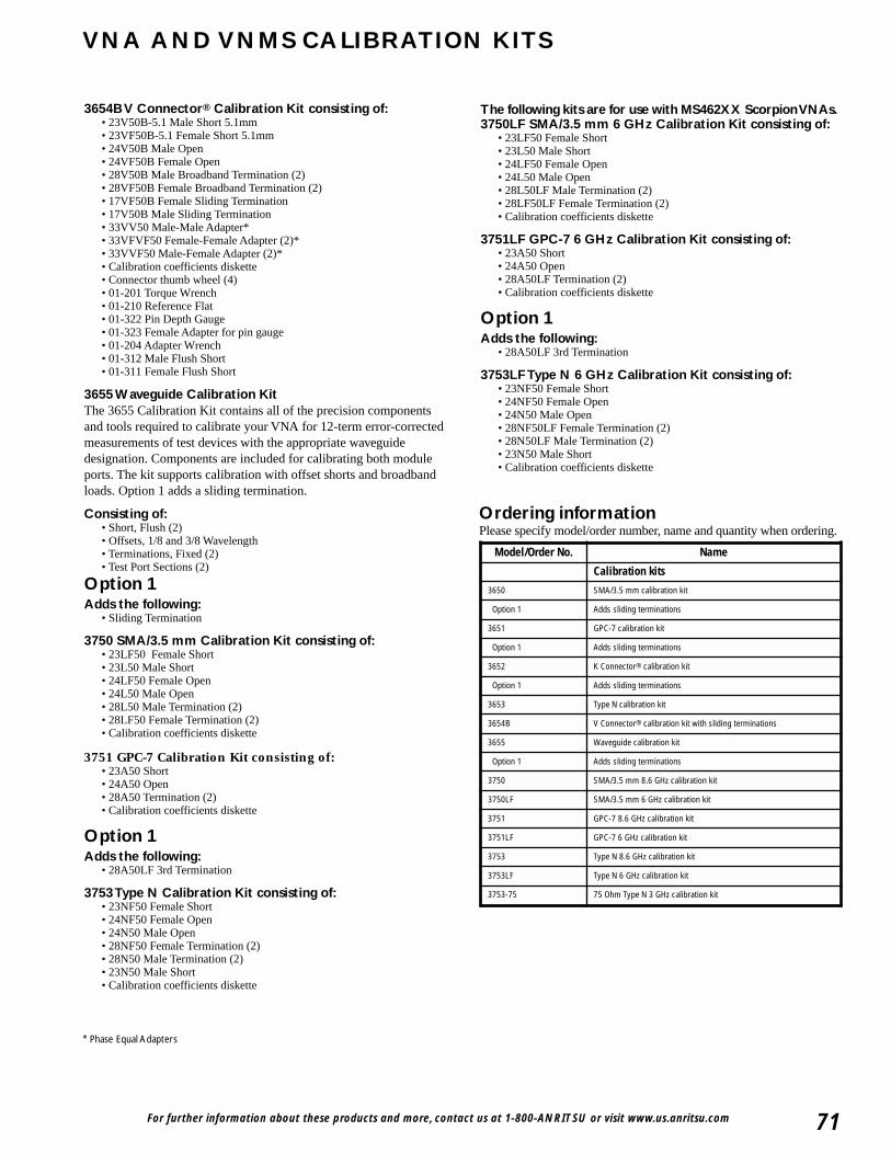
For further information about these products and more, contact us at 1-800-ANRITSU or visit www.us.anritsu.com 71
VNA AND VNMS CALIBRATION KITS
3654B V Connector® Calibration Kit consisting of:• 23V50B-5.1 Male Short 5.1mm • 23VF50B-5.1 Female Short 5.1mm• 24V50B Male Open • 24VF50B Female Open • 28V50B Male Broadband Termination (2)• 28VF50B Female Broadband Termination (2)• 17VF50B Female Sliding Termination• 17V50B Male Sliding Termination• 33VV50 Male-Male Adapter*• 33VFVF50 Female-Female Adapter (2)*• 33VVF50 Male-Female Adapter (2)*• Calibration coefficients diskette• Connector thumb wheel (4) • 01-201 Torque Wrench• 01-210 Reference Flat• 01-322 Pin Depth Gauge • 01-323 Female Adapter for pin gauge • 01-204 Adapter Wrench • 01-312 Male Flush Short • 01-311 Female Flush Short
3655 Waveguide Calibration KitThe 3655 Calibration Kit contains all of the precision componentsand tools required to calibrate your VNA for 12-term error-correctedmeasurements of test devices with the appropriate waveguidedesignation. Components are included for calibrating both moduleports. The kit supports calibration with offset shorts and broadbandloads. Option 1 adds a sliding termination.
Consisting of:• Short, Flush (2)• Offsets, 1/8 and 3/8 Wavelength• Terminations, Fixed (2)• Test Port Sections (2)
Option 1Adds the following:
• Sliding Termination
3750 SMA/3.5 mm Calibration Kit consisting of:• 23LF50 Female Short• 23L50 Male Short• 24LF50 Female Open• 24L50 Male Open• 28L50 Male Termination (2)• 28LF50 Female Termination (2)• Calibration coefficients diskette
3751 GPC-7 Calibration Kit consisting of:• 23A50 Short• 24A50 Open• 28A50 Termination (2)• Calibration coefficients diskette
Option 1Adds the following:
• 28A50LF 3rd Termination
3753 Type N Calibration Kit consisting of:• 23NF50 Female Short• 24NF50 Female Open• 24N50 Male Open• 28NF50 Female Termination (2)• 28N50 Male Termination (2)• 23N50 Male Short• Calibration coefficients diskette
The following kits are for use with MS462XX Scorpion VNAs.3750LF SMA/3.5 mm 6 GHz Calibration Kit consisting of:
• 23LF50 Female Short• 23L50 Male Short• 24LF50 Female Open• 24L50 Male Open• 28L50LF Male Termination (2)• 28LF50LF Female Termination (2)• Calibration coefficients diskette
3751LF GPC-7 6 GHz Calibration Kit consisting of:• 23A50 Short• 24A50 Open• 28A50LF Termination (2)• Calibration coefficients diskette
Option 1Adds the following:
• 28A50LF 3rd Termination
3753LF Type N 6 GHz Calibration Kit consisting of:• 23NF50 Female Short• 24NF50 Female Open• 24N50 Male Open• 28NF50LF Female Termination (2)• 28N50LF Male Termination (2)• 23N50 Male Short• Calibration coefficients diskette
Ordering informationPlease specify model/order number, name and quantity when ordering.
* Phase Equal Adapters
Model/Order No. Name
Calibration kits
3650 SMA/3.5 mm calibration kit
Option 1 Adds sliding terminations
3651 GPC-7 calibration kit
Option 1 Adds sliding terminations
3652 K Connector® calibration kit
Option 1 Adds sliding terminations
3653 Type N calibration kit
3654B V Connector® calibration kit with sliding terminations
3655 Waveguide calibration kit
Option 1 Adds sliding terminations
3750 SMA/3.5 mm 8.6 GHz calibration kit
3750LF SMA/3.5 mm 6 GHz calibration kit
3751 GPC-7 8.6 GHz calibration kit
3751LF GPC-7 6 GHz calibration kit
3753 Type N 8.6 GHz calibration kit
3753LF Type N 6 GHz calibration kit
3753-75 75 Ohm Type N 3 GHz calibration kit
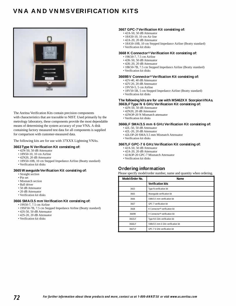
For further information about these products and more, contact us at 1-800-ANRITSU or visit www.us.anritsu.com72
VNA AND VNMS VERIFICATION KITS
The Anritsu Verification Kits contain precision componentswith characteristics that are traceable to NIST. Used primarily by themetrology laboratory, these components provide the most dependablemeans of determining the system accuracy of your VNA. A diskcontaining factory measured test data for all components is suppliedfor comparison with customer-measured data.
The following kits are for use with 37XXX Lightning VNAs.
3663 Type N Verification Kit consisting of:• 42N-50, 50 dB Attenuator• 18N50-10, 10 cm Airline• 42N20, 20 dB Attenuator• 18N50-10B, 10 cm Stepped Impedance Airline (Beatty standard)• Verification kit disks
3665 Waveguide Verification Kit consisting of:• Straight section• Pin set• Mismatch section• Ball driver• 50 dB Attenuator• 20 dB Attenuator• Verification kit disks
3666 SMA/3.5 mm Verification Kit consisting of:• 19S50-7, 7.5 cm Airline• 19SF50-7B, 7.5 cm Stepped Impedance Airline (Beatty standard)• 42S-50, 50 dB Attenuator• 42S-20, 20 dB Attenuator• Verification kit disks
3667 GPC-7 Verification Kit consisting of:• 42A-50, 50 dB Attenuator• 18A50-10, 10 cm Air line• 42A-20, 20 dB Attenuator• 18A50-10B, 10 cm Stepped Impedance Airline (Beatty standard)• Verification kit disks
3668 K Connector® Verification Kit consisting of:• 19K50-7, 7.5 cm Airline• 42K-50, 50 dB Attenuator• 42K-20, 20 dB Attenuator• 18K50-7B, 7.5 cm Stepped Impedance Airline (Beatty standard)• Verification kit disks
3669B V Connector® Verification Kit consisting of:• 42V-40, 40 dB Attenuator• 42V-20, 20 dB Attenuator• 19V50-5, 5 cm Airline• 18V50-5B, 5 cm Stepped Impedance Airline (Beatty standard)• Verification kit disks
The following kits are for use with MS462XX Scorpion VNAs.3663LF Type N 6 GHz Verification Kit consisting of:
• 42N-50, 50 dB Attenuator• 42N20, 20 dB Attenuator• 42NOP-20 N Mismatch attenuator• Verification kit disks
3666LF SMA/3.5 mm 6 GHz Verification Kit consisting of:• 42L-50, 50 dB Attenuator• 42L-20, 20 dB Attenuator• 42LOP-20 SMA/3.5 mm Mismatch Attenuator• Verification kit disks
3667LF GPC-7 6 GHz Verification Kit consisting of:• 42A-50, 50 dB Attenuator• 42A-20, 20 dB Attenuator• 42AOP-20 GPC-7 Mismatch Attenuator• Verification kit disks
Ordering informationPlease specify model/order number, name and quantity when ordering.
3669B
Model/Order No. Name
Verification kits
3663 Type N verification kit
3665 Waveguide verification kit
3666 SMA/3.5 mm verification kit
3667 GPC-7 verification kit
3668 K Connector® verification kit
3669B V Connector® verification kit
3663LF Type N 6 GHz verification kit
3666LF SMA/3.5 mm 6 GHz verification kit
3667LF GPC-7 6 GHz verification kit
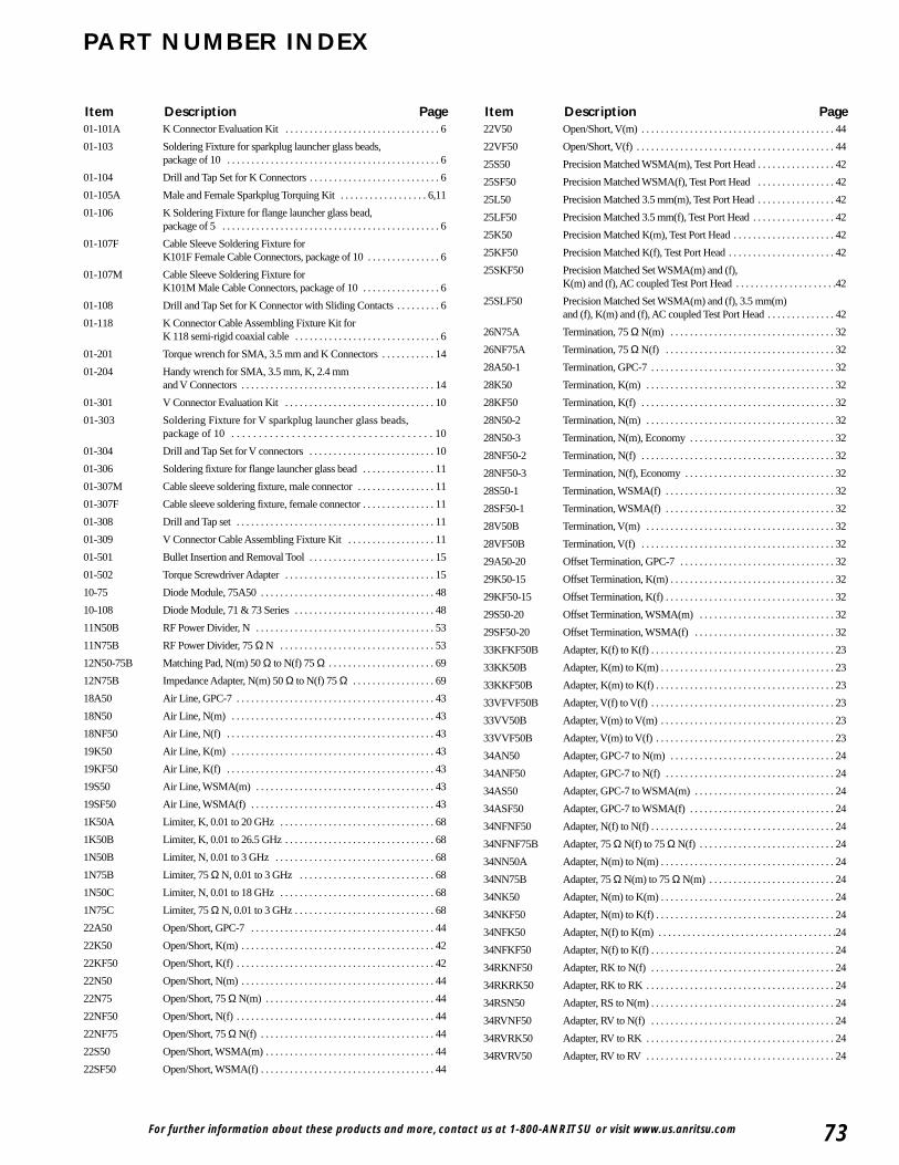
For further information about these products and more, contact us at 1-800-ANRITSU or visit www.us.anritsu.com 73
PART NUMBER INDEX
01-101A K Connector Evaluation Kit . . . . . . . . . . . . . . . . . . . . . . . . . . . . . . . . 6
01-103 Soldering Fixture for sparkplug launcher glass beads,package of 10 . . . . . . . . . . . . . . . . . . . . . . . . . . . . . . . . . . . . . . . . . . . . 6
01-104 Drill and Tap Set for K Connectors . . . . . . . . . . . . . . . . . . . . . . . . . . . 6
01-105A Male and Female Sparkplug Torquing Kit . . . . . . . . . . . . . . . . . . 6,11
01-106 K Soldering Fixture for flange launcher glass bead,package of 5 . . . . . . . . . . . . . . . . . . . . . . . . . . . . . . . . . . . . . . . . . . . . . 6
01-107F Cable Sleeve Soldering Fixture for K101F Female Cable Connectors, package of 10 . . . . . . . . . . . . . . . 6
01-107M Cable Sleeve Soldering Fixture for K101M Male Cable Connectors, package of 10 . . . . . . . . . . . . . . . . 6
01-108 Drill and Tap Set for K Connector with Sliding Contacts . . . . . . . . . 6
01-118 K Connector Cable Assembling Fixture Kit for K 118 semi-rigid coaxial cable . . . . . . . . . . . . . . . . . . . . . . . . . . . . . . 6
01-201 Torque wrench for SMA, 3.5 mm and K Connectors . . . . . . . . . . . 14
01-204 Handy wrench for SMA, 3.5 mm, K, 2.4 mm and V Connectors . . . . . . . . . . . . . . . . . . . . . . . . . . . . . . . . . . . . . . . . 14
01-301 V Connector Evaluation Kit . . . . . . . . . . . . . . . . . . . . . . . . . . . . . . . 10
01-303 Soldering Fixture for V sparkplug launcher glass beads,package of 10 . . . . . . . . . . . . . . . . . . . . . . . . . . . . . . . . . . . . . 10
01-304 Drill and Tap Set for V connectors . . . . . . . . . . . . . . . . . . . . . . . . . . 10
01-306 Soldering fixture for flange launcher glass bead . . . . . . . . . . . . . . . 11
01-307M Cable sleeve soldering fixture, male connector . . . . . . . . . . . . . . . . 11
01-307F Cable sleeve soldering fixture, female connector . . . . . . . . . . . . . . . 11
01-308 Drill and Tap set . . . . . . . . . . . . . . . . . . . . . . . . . . . . . . . . . . . . . . . . . 11
01-309 V Connector Cable Assembling Fixture Kit . . . . . . . . . . . . . . . . . . 11
01-501 Bullet Insertion and Removal Tool . . . . . . . . . . . . . . . . . . . . . . . . . . 15
01-502 Torque Screwdriver Adapter . . . . . . . . . . . . . . . . . . . . . . . . . . . . . . . 15
10-75 Diode Module, 75A50 . . . . . . . . . . . . . . . . . . . . . . . . . . . . . . . . . . . . 48
10-108 Diode Module, 71 & 73 Series . . . . . . . . . . . . . . . . . . . . . . . . . . . . . 48
11N50B RF Power Divider, N . . . . . . . . . . . . . . . . . . . . . . . . . . . . . . . . . . . . . 53
11N75B RF Power Divider, 75 Ω N . . . . . . . . . . . . . . . . . . . . . . . . . . . . . . . . 53
12N50-75B Matching Pad, N(m) 50 Ω to N(f) 75 Ω . . . . . . . . . . . . . . . . . . . . . . 69
12N75B Impedance Adapter, N(m) 50 Ω to N(f) 75 Ω . . . . . . . . . . . . . . . . . 69
18A50 Air Line, GPC-7 . . . . . . . . . . . . . . . . . . . . . . . . . . . . . . . . . . . . . . . . . 43
18N50 Air Line, N(m) . . . . . . . . . . . . . . . . . . . . . . . . . . . . . . . . . . . . . . . . . . 43
18NF50 Air Line, N(f) . . . . . . . . . . . . . . . . . . . . . . . . . . . . . . . . . . . . . . . . . . . 43
19K50 Air Line, K(m) . . . . . . . . . . . . . . . . . . . . . . . . . . . . . . . . . . . . . . . . . . 43
19KF50 Air Line, K(f) . . . . . . . . . . . . . . . . . . . . . . . . . . . . . . . . . . . . . . . . . . . 43
19S50 Air Line, WSMA(m) . . . . . . . . . . . . . . . . . . . . . . . . . . . . . . . . . . . . . 43
19SF50 Air Line, WSMA(f) . . . . . . . . . . . . . . . . . . . . . . . . . . . . . . . . . . . . . . 43
1K50A Limiter, K, 0.01 to 20 GHz . . . . . . . . . . . . . . . . . . . . . . . . . . . . . . . . 68
1K50B Limiter, K, 0.01 to 26.5 GHz . . . . . . . . . . . . . . . . . . . . . . . . . . . . . . . 68
1N50B Limiter, N, 0.01 to 3 GHz . . . . . . . . . . . . . . . . . . . . . . . . . . . . . . . . . 68
1N75B Limiter, 75 Ω N, 0.01 to 3 GHz . . . . . . . . . . . . . . . . . . . . . . . . . . . . 68
1N50C Limiter, N, 0.01 to 18 GHz . . . . . . . . . . . . . . . . . . . . . . . . . . . . . . . . 68
1N75C Limiter, 75 Ω N, 0.01 to 3 GHz . . . . . . . . . . . . . . . . . . . . . . . . . . . . . 68
22A50 Open/Short, GPC-7 . . . . . . . . . . . . . . . . . . . . . . . . . . . . . . . . . . . . . . 44
22K50 Open/Short, K(m) . . . . . . . . . . . . . . . . . . . . . . . . . . . . . . . . . . . . . . . . 42
22KF50 Open/Short, K(f) . . . . . . . . . . . . . . . . . . . . . . . . . . . . . . . . . . . . . . . . . 42
22N50 Open/Short, N(m) . . . . . . . . . . . . . . . . . . . . . . . . . . . . . . . . . . . . . . . . 44
22N75 Open/Short, 75 Ω N(m) . . . . . . . . . . . . . . . . . . . . . . . . . . . . . . . . . . . 44
22NF50 Open/Short, N(f) . . . . . . . . . . . . . . . . . . . . . . . . . . . . . . . . . . . . . . . . . 44
22NF75 Open/Short, 75 Ω N(f) . . . . . . . . . . . . . . . . . . . . . . . . . . . . . . . . . . . . 44
22S50 Open/Short, WSMA(m) . . . . . . . . . . . . . . . . . . . . . . . . . . . . . . . . . . . 44
22SF50 Open/Short, WSMA(f) . . . . . . . . . . . . . . . . . . . . . . . . . . . . . . . . . . . . 44
22V50 Open/Short, V(m) . . . . . . . . . . . . . . . . . . . . . . . . . . . . . . . . . . . . . . . . 44
22VF50 Open/Short, V(f) . . . . . . . . . . . . . . . . . . . . . . . . . . . . . . . . . . . . . . . . . 44
25S50 Precision Matched WSMA(m), Test Port Head . . . . . . . . . . . . . . . . 42
25SF50 Precision Matched WSMA(f), Test Port Head . . . . . . . . . . . . . . . . 42
25L50 Precision Matched 3.5 mm(m), Test Port Head . . . . . . . . . . . . . . . . 42
25LF50 Precision Matched 3.5 mm(f), Test Port Head . . . . . . . . . . . . . . . . . 42
25K50 Precision Matched K(m), Test Port Head . . . . . . . . . . . . . . . . . . . . . 42
25KF50 Precision Matched K(f), Test Port Head . . . . . . . . . . . . . . . . . . . . . . 42
25SKF50 Precision Matched Set WSMA(m) and (f),K(m) and (f), AC coupled Test Port Head . . . . . . . . . . . . . . . . . . . . .42
25SLF50 Precision Matched Set WSMA(m) and (f), 3.5 mm(m) and (f), K(m) and (f), AC coupled Test Port Head . . . . . . . . . . . . . . 42
26N75A Termination, 75 Ω N(m) . . . . . . . . . . . . . . . . . . . . . . . . . . . . . . . . . . 32
26NF75A Termination, 75 Ω N(f) . . . . . . . . . . . . . . . . . . . . . . . . . . . . . . . . . . . 32
28A50-1 Termination, GPC-7 . . . . . . . . . . . . . . . . . . . . . . . . . . . . . . . . . . . . . . 32
28K50 Termination, K(m) . . . . . . . . . . . . . . . . . . . . . . . . . . . . . . . . . . . . . . . 32
28KF50 Termination, K(f) . . . . . . . . . . . . . . . . . . . . . . . . . . . . . . . . . . . . . . . . 32
28N50-2 Termination, N(m) . . . . . . . . . . . . . . . . . . . . . . . . . . . . . . . . . . . . . . . 32
28N50-3 Termination, N(m), Economy . . . . . . . . . . . . . . . . . . . . . . . . . . . . . . 32
28NF50-2 Termination, N(f) . . . . . . . . . . . . . . . . . . . . . . . . . . . . . . . . . . . . . . . . 32
28NF50-3 Termination, N(f), Economy . . . . . . . . . . . . . . . . . . . . . . . . . . . . . . . 32
28S50-1 Termination, WSMA(f) . . . . . . . . . . . . . . . . . . . . . . . . . . . . . . . . . . . 32
28SF50-1 Termination, WSMA(f) . . . . . . . . . . . . . . . . . . . . . . . . . . . . . . . . . . . 32
28V50B Termination, V(m) . . . . . . . . . . . . . . . . . . . . . . . . . . . . . . . . . . . . . . . 32
28VF50B Termination, V(f) . . . . . . . . . . . . . . . . . . . . . . . . . . . . . . . . . . . . . . . . 32
29A50-20 Offset Termination, GPC-7 . . . . . . . . . . . . . . . . . . . . . . . . . . . . . . . . 32
29K50-15 Offset Termination, K(m) . . . . . . . . . . . . . . . . . . . . . . . . . . . . . . . . . . 32
29KF50-15 Offset Termination, K(f) . . . . . . . . . . . . . . . . . . . . . . . . . . . . . . . . . . . 32
29S50-20 Offset Termination, WSMA(m) . . . . . . . . . . . . . . . . . . . . . . . . . . . . 32
29SF50-20 Offset Termination, WSMA(f) . . . . . . . . . . . . . . . . . . . . . . . . . . . . . 32
33KFKF50B Adapter, K(f) to K(f) . . . . . . . . . . . . . . . . . . . . . . . . . . . . . . . . . . . . . . 23
33KK50B Adapter, K(m) to K(m) . . . . . . . . . . . . . . . . . . . . . . . . . . . . . . . . . . . . 23
33KKF50B Adapter, K(m) to K(f) . . . . . . . . . . . . . . . . . . . . . . . . . . . . . . . . . . . . . 23
33VFVF50B Adapter, V(f) to V(f) . . . . . . . . . . . . . . . . . . . . . . . . . . . . . . . . . . . . . . 23
33VV50B Adapter, V(m) to V(m) . . . . . . . . . . . . . . . . . . . . . . . . . . . . . . . . . . . . 23
33VVF50B Adapter, V(m) to V(f) . . . . . . . . . . . . . . . . . . . . . . . . . . . . . . . . . . . . . 23
34AN50 Adapter, GPC-7 to N(m) . . . . . . . . . . . . . . . . . . . . . . . . . . . . . . . . . . 24
34ANF50 Adapter, GPC-7 to N(f) . . . . . . . . . . . . . . . . . . . . . . . . . . . . . . . . . . . 24
34AS50 Adapter, GPC-7 to WSMA(m) . . . . . . . . . . . . . . . . . . . . . . . . . . . . . 24
34ASF50 Adapter, GPC-7 to WSMA(f) . . . . . . . . . . . . . . . . . . . . . . . . . . . . . . 24
34NFNF50 Adapter, N(f) to N(f) . . . . . . . . . . . . . . . . . . . . . . . . . . . . . . . . . . . . . . 24
34NFNF75B Adapter, 75 Ω N(f) to 75 Ω N(f) . . . . . . . . . . . . . . . . . . . . . . . . . . . . 24
34NN50A Adapter, N(m) to N(m) . . . . . . . . . . . . . . . . . . . . . . . . . . . . . . . . . . . . 24
34NN75B Adapter, 75 Ω N(m) to 75 Ω N(m) . . . . . . . . . . . . . . . . . . . . . . . . . . 24
34NK50 Adapter, N(m) to K(m) . . . . . . . . . . . . . . . . . . . . . . . . . . . . . . . . . . . . 24
34NKF50 Adapter, N(m) to K(f) . . . . . . . . . . . . . . . . . . . . . . . . . . . . . . . . . . . . . 24
34NFK50 Adapter, N(f) to K(m) . . . . . . . . . . . . . . . . . . . . . . . . . . . . . . . . . . . . .24
34NFKF50 Adapter, N(f) to K(f) . . . . . . . . . . . . . . . . . . . . . . . . . . . . . . . . . . . . . . 24
34RKNF50 Adapter, RK to N(f) . . . . . . . . . . . . . . . . . . . . . . . . . . . . . . . . . . . . . . 24
34RKRK50 Adapter, RK to RK . . . . . . . . . . . . . . . . . . . . . . . . . . . . . . . . . . . . . . . 24
34RSN50 Adapter, RS to N(m) . . . . . . . . . . . . . . . . . . . . . . . . . . . . . . . . . . . . . . 24
34RVNF50 Adapter, RV to N(f) . . . . . . . . . . . . . . . . . . . . . . . . . . . . . . . . . . . . . . 24
34RVRK50 Adapter, RV to RK . . . . . . . . . . . . . . . . . . . . . . . . . . . . . . . . . . . . . . . 24
34RVRV50 Adapter, RV to RV . . . . . . . . . . . . . . . . . . . . . . . . . . . . . . . . . . . . . . . 24
Item Description Page Item Description Page
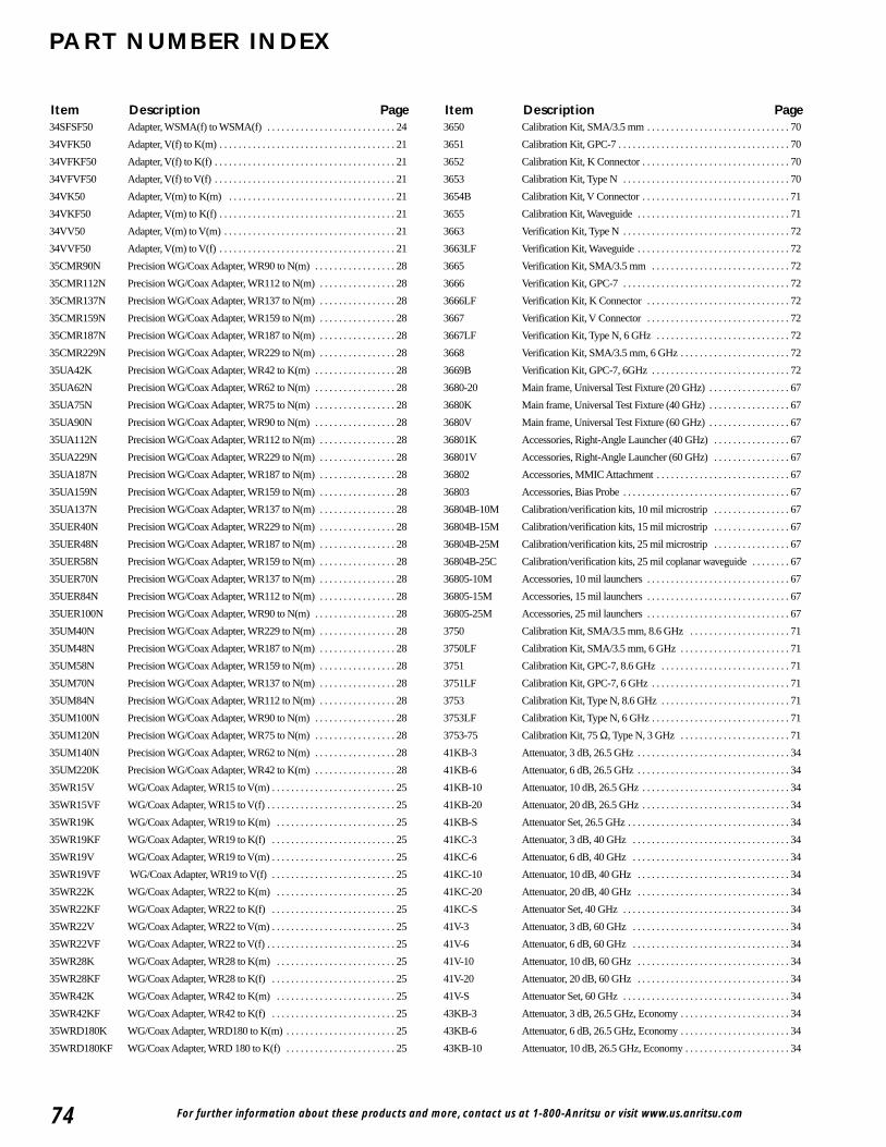
74
PART NUMBER INDEX
For further information about these products and more, contact us at 1-800-Anritsu or visit www.us.anritsu.com
34SFSF50 Adapter, WSMA(f) to WSMA(f) . . . . . . . . . . . . . . . . . . . . . . . . . . . 24
34VFK50 Adapter, V(f) to K(m) . . . . . . . . . . . . . . . . . . . . . . . . . . . . . . . . . . . . . 21
34VFKF50 Adapter, V(f) to K(f) . . . . . . . . . . . . . . . . . . . . . . . . . . . . . . . . . . . . . . 21
34VFVF50 Adapter, V(f) to V(f) . . . . . . . . . . . . . . . . . . . . . . . . . . . . . . . . . . . . . . 21
34VK50 Adapter, V(m) to K(m) . . . . . . . . . . . . . . . . . . . . . . . . . . . . . . . . . . . 21
34VKF50 Adapter, V(m) to K(f) . . . . . . . . . . . . . . . . . . . . . . . . . . . . . . . . . . . . . 21
34VV50 Adapter, V(m) to V(m) . . . . . . . . . . . . . . . . . . . . . . . . . . . . . . . . . . . . 21
34VVF50 Adapter, V(m) to V(f) . . . . . . . . . . . . . . . . . . . . . . . . . . . . . . . . . . . . . 21
35CMR90N Precision WG/Coax Adapter, WR90 to N(m) . . . . . . . . . . . . . . . . . 28
35CMR112N Precision WG/Coax Adapter, WR112 to N(m) . . . . . . . . . . . . . . . . 28
35CMR137N Precision WG/Coax Adapter, WR137 to N(m) . . . . . . . . . . . . . . . . 28
35CMR159N Precision WG/Coax Adapter, WR159 to N(m) . . . . . . . . . . . . . . . . 28
35CMR187N Precision WG/Coax Adapter, WR187 to N(m) . . . . . . . . . . . . . . . . 28
35CMR229N Precision WG/Coax Adapter, WR229 to N(m) . . . . . . . . . . . . . . . . 28
35UA42K Precision WG/Coax Adapter, WR42 to K(m) . . . . . . . . . . . . . . . . . 28
35UA62N Precision WG/Coax Adapter, WR62 to N(m) . . . . . . . . . . . . . . . . . 28
35UA75N Precision WG/Coax Adapter, WR75 to N(m) . . . . . . . . . . . . . . . . . 28
35UA90N Precision WG/Coax Adapter, WR90 to N(m) . . . . . . . . . . . . . . . . . 28
35UA112N Precision WG/Coax Adapter, WR112 to N(m) . . . . . . . . . . . . . . . . 28
35UA229N Precision WG/Coax Adapter, WR229 to N(m) . . . . . . . . . . . . . . . . 28
35UA187N Precision WG/Coax Adapter, WR187 to N(m) . . . . . . . . . . . . . . . . 28
35UA159N Precision WG/Coax Adapter, WR159 to N(m) . . . . . . . . . . . . . . . . 28
35UA137N Precision WG/Coax Adapter, WR137 to N(m) . . . . . . . . . . . . . . . . 28
35UER40N Precision WG/Coax Adapter, WR229 to N(m) . . . . . . . . . . . . . . . . 28
35UER48N Precision WG/Coax Adapter, WR187 to N(m) . . . . . . . . . . . . . . . . 28
35UER58N Precision WG/Coax Adapter, WR159 to N(m) . . . . . . . . . . . . . . . . 28
35UER70N Precision WG/Coax Adapter, WR137 to N(m) . . . . . . . . . . . . . . . . 28
35UER84N Precision WG/Coax Adapter, WR112 to N(m) . . . . . . . . . . . . . . . . 28
35UER100N Precision WG/Coax Adapter, WR90 to N(m) . . . . . . . . . . . . . . . . . 28
35UM40N Precision WG/Coax Adapter, WR229 to N(m) . . . . . . . . . . . . . . . . 28
35UM48N Precision WG/Coax Adapter, WR187 to N(m) . . . . . . . . . . . . . . . . 28
35UM58N Precision WG/Coax Adapter, WR159 to N(m) . . . . . . . . . . . . . . . . 28
35UM70N Precision WG/Coax Adapter, WR137 to N(m) . . . . . . . . . . . . . . . . 28
35UM84N Precision WG/Coax Adapter, WR112 to N(m) . . . . . . . . . . . . . . . . 28
35UM100N Precision WG/Coax Adapter, WR90 to N(m) . . . . . . . . . . . . . . . . . 28
35UM120N Precision WG/Coax Adapter, WR75 to N(m) . . . . . . . . . . . . . . . . . 28
35UM140N Precision WG/Coax Adapter, WR62 to N(m) . . . . . . . . . . . . . . . . . 28
35UM220K Precision WG/Coax Adapter, WR42 to K(m) . . . . . . . . . . . . . . . . . 28
35WR15V WG/Coax Adapter, WR15 to V(m) . . . . . . . . . . . . . . . . . . . . . . . . . . 25
35WR15VF WG/Coax Adapter, WR15 to V(f) . . . . . . . . . . . . . . . . . . . . . . . . . . . 25
35WR19K WG/Coax Adapter, WR19 to K(m) . . . . . . . . . . . . . . . . . . . . . . . . . 25
35WR19KF WG/Coax Adapter, WR19 to K(f) . . . . . . . . . . . . . . . . . . . . . . . . . . 25
35WR19V WG/Coax Adapter, WR19 to V(m) . . . . . . . . . . . . . . . . . . . . . . . . . . 25
35WR19VF WG/Coax Adapter, WR19 to V(f) . . . . . . . . . . . . . . . . . . . . . . . . . . 25
35WR22K WG/Coax Adapter, WR22 to K(m) . . . . . . . . . . . . . . . . . . . . . . . . . 25
35WR22KF WG/Coax Adapter, WR22 to K(f) . . . . . . . . . . . . . . . . . . . . . . . . . . 25
35WR22V WG/Coax Adapter, WR22 to V(m) . . . . . . . . . . . . . . . . . . . . . . . . . . 25
35WR22VF WG/Coax Adapter, WR22 to V(f) . . . . . . . . . . . . . . . . . . . . . . . . . . . 25
35WR28K WG/Coax Adapter, WR28 to K(m) . . . . . . . . . . . . . . . . . . . . . . . . . 25
35WR28KF WG/Coax Adapter, WR28 to K(f) . . . . . . . . . . . . . . . . . . . . . . . . . . 25
35WR42K WG/Coax Adapter, WR42 to K(m) . . . . . . . . . . . . . . . . . . . . . . . . . 25
35WR42KF WG/Coax Adapter, WR42 to K(f) . . . . . . . . . . . . . . . . . . . . . . . . . . 25
35WRD180K WG/Coax Adapter, WRD180 to K(m) . . . . . . . . . . . . . . . . . . . . . . . 25
35WRD180KF WG/Coax Adapter, WRD 180 to K(f) . . . . . . . . . . . . . . . . . . . . . . . 25
3650 Calibration Kit, SMA/3.5 mm . . . . . . . . . . . . . . . . . . . . . . . . . . . . . . 70
3651 Calibration Kit, GPC-7 . . . . . . . . . . . . . . . . . . . . . . . . . . . . . . . . . . . . 70
3652 Calibration Kit, K Connector . . . . . . . . . . . . . . . . . . . . . . . . . . . . . . . 70
3653 Calibration Kit, Type N . . . . . . . . . . . . . . . . . . . . . . . . . . . . . . . . . . . 70
3654B Calibration Kit, V Connector . . . . . . . . . . . . . . . . . . . . . . . . . . . . . . . 71
3655 Calibration Kit, Waveguide . . . . . . . . . . . . . . . . . . . . . . . . . . . . . . . . 71
3663 Verification Kit, Type N . . . . . . . . . . . . . . . . . . . . . . . . . . . . . . . . . . . 72
3663LF Verification Kit, Waveguide . . . . . . . . . . . . . . . . . . . . . . . . . . . . . . . . 72
3665 Verification Kit, SMA/3.5 mm . . . . . . . . . . . . . . . . . . . . . . . . . . . . . 72
3666 Verification Kit, GPC-7 . . . . . . . . . . . . . . . . . . . . . . . . . . . . . . . . . . . 72
3666LF Verification Kit, K Connector . . . . . . . . . . . . . . . . . . . . . . . . . . . . . . 72
3667 Verification Kit, V Connector . . . . . . . . . . . . . . . . . . . . . . . . . . . . . . 72
3667LF Verification Kit, Type N, 6 GHz . . . . . . . . . . . . . . . . . . . . . . . . . . . . 72
3668 Verification Kit, SMA/3.5 mm, 6 GHz . . . . . . . . . . . . . . . . . . . . . . . 72
3669B Verification Kit, GPC-7, 6GHz . . . . . . . . . . . . . . . . . . . . . . . . . . . . . 72
3680-20 Main frame, Universal Test Fixture (20 GHz) . . . . . . . . . . . . . . . . . 67
3680K Main frame, Universal Test Fixture (40 GHz) . . . . . . . . . . . . . . . . . 67
3680V Main frame, Universal Test Fixture (60 GHz) . . . . . . . . . . . . . . . . . 67
36801K Accessories, Right-Angle Launcher (40 GHz) . . . . . . . . . . . . . . . . 67
36801V Accessories, Right-Angle Launcher (60 GHz) . . . . . . . . . . . . . . . . 67
36802 Accessories, MMIC Attachment . . . . . . . . . . . . . . . . . . . . . . . . . . . . 67
36803 Accessories, Bias Probe . . . . . . . . . . . . . . . . . . . . . . . . . . . . . . . . . . . 67
36804B-10M Calibration/verification kits, 10 mil microstrip . . . . . . . . . . . . . . . . 67
36804B-15M Calibration/verification kits, 15 mil microstrip . . . . . . . . . . . . . . . . 67
36804B-25M Calibration/verification kits, 25 mil microstrip . . . . . . . . . . . . . . . . 67
36804B-25C Calibration/verification kits, 25 mil coplanar waveguide . . . . . . . . 67
36805-10M Accessories, 10 mil launchers . . . . . . . . . . . . . . . . . . . . . . . . . . . . . . 67
36805-15M Accessories, 15 mil launchers . . . . . . . . . . . . . . . . . . . . . . . . . . . . . . 67
36805-25M Accessories, 25 mil launchers . . . . . . . . . . . . . . . . . . . . . . . . . . . . . . 67
3750 Calibration Kit, SMA/3.5 mm, 8.6 GHz . . . . . . . . . . . . . . . . . . . . . 71
3750LF Calibration Kit, SMA/3.5 mm, 6 GHz . . . . . . . . . . . . . . . . . . . . . . . 71
3751 Calibration Kit, GPC-7, 8.6 GHz . . . . . . . . . . . . . . . . . . . . . . . . . . . 71
3751LF Calibration Kit, GPC-7, 6 GHz . . . . . . . . . . . . . . . . . . . . . . . . . . . . . 71
3753 Calibration Kit, Type N, 8.6 GHz . . . . . . . . . . . . . . . . . . . . . . . . . . . 71
3753LF Calibration Kit, Type N, 6 GHz . . . . . . . . . . . . . . . . . . . . . . . . . . . . . 71
3753-75 Calibration Kit, 75 Ω, Type N, 3 GHz . . . . . . . . . . . . . . . . . . . . . . . 71
41KB-3 Attenuator, 3 dB, 26.5 GHz . . . . . . . . . . . . . . . . . . . . . . . . . . . . . . . . 34
41KB-6 Attenuator, 6 dB, 26.5 GHz . . . . . . . . . . . . . . . . . . . . . . . . . . . . . . . . 34
41KB-10 Attenuator, 10 dB, 26.5 GHz . . . . . . . . . . . . . . . . . . . . . . . . . . . . . . . 34
41KB-20 Attenuator, 20 dB, 26.5 GHz . . . . . . . . . . . . . . . . . . . . . . . . . . . . . . . 34
41KB-S Attenuator Set, 26.5 GHz . . . . . . . . . . . . . . . . . . . . . . . . . . . . . . . . . . 34
41KC-3 Attenuator, 3 dB, 40 GHz . . . . . . . . . . . . . . . . . . . . . . . . . . . . . . . . . 34
41KC-6 Attenuator, 6 dB, 40 GHz . . . . . . . . . . . . . . . . . . . . . . . . . . . . . . . . . 34
41KC-10 Attenuator, 10 dB, 40 GHz . . . . . . . . . . . . . . . . . . . . . . . . . . . . . . . . 34
41KC-20 Attenuator, 20 dB, 40 GHz . . . . . . . . . . . . . . . . . . . . . . . . . . . . . . . . 34
41KC-S Attenuator Set, 40 GHz . . . . . . . . . . . . . . . . . . . . . . . . . . . . . . . . . . . 34
41V-3 Attenuator, 3 dB, 60 GHz . . . . . . . . . . . . . . . . . . . . . . . . . . . . . . . . . 34
41V-6 Attenuator, 6 dB, 60 GHz . . . . . . . . . . . . . . . . . . . . . . . . . . . . . . . . . 34
41V-10 Attenuator, 10 dB, 60 GHz . . . . . . . . . . . . . . . . . . . . . . . . . . . . . . . . 34
41V-20 Attenuator, 20 dB, 60 GHz . . . . . . . . . . . . . . . . . . . . . . . . . . . . . . . . 34
41V-S Attenuator Set, 60 GHz . . . . . . . . . . . . . . . . . . . . . . . . . . . . . . . . . . . 34
43KB-3 Attenuator, 3 dB, 26.5 GHz, Economy . . . . . . . . . . . . . . . . . . . . . . . 34
43KB-6 Attenuator, 6 dB, 26.5 GHz, Economy . . . . . . . . . . . . . . . . . . . . . . . 34
43KB-10 Attenuator, 10 dB, 26.5 GHz, Economy . . . . . . . . . . . . . . . . . . . . . . 34
Item Description Page Item Description Page
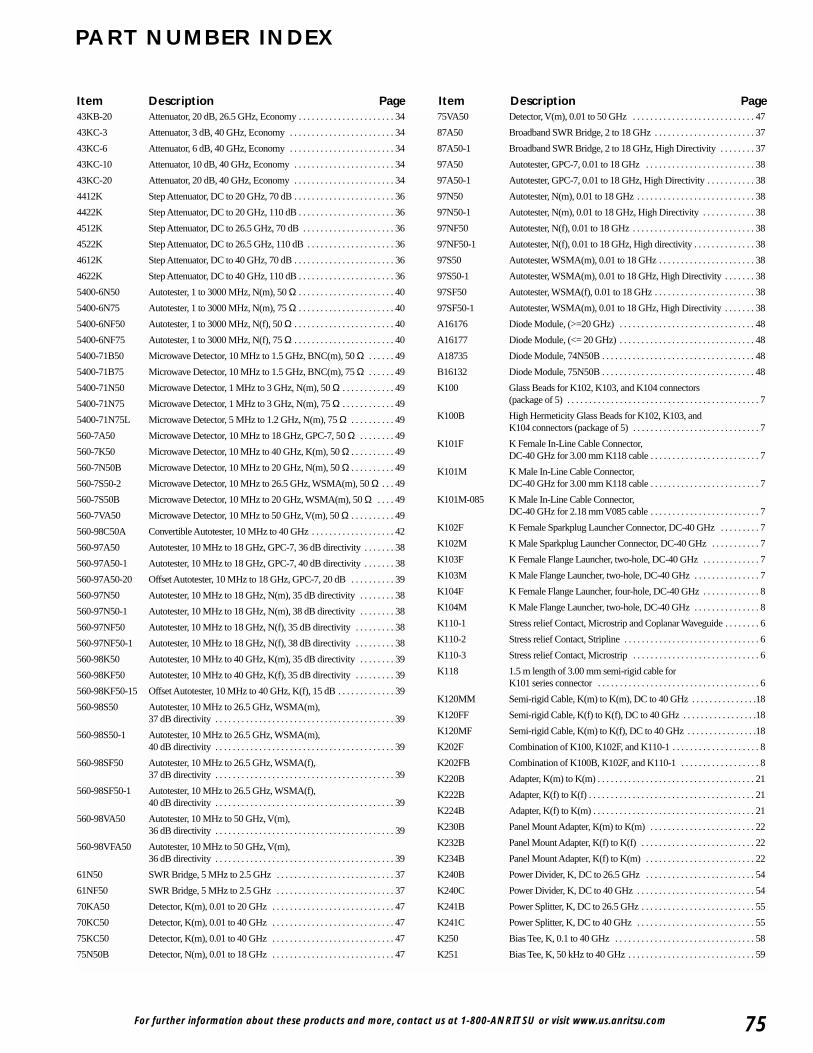
For further information about these products and more, contact us at 1-800-ANRITSU or visit www.us.anritsu.com 75
PART NUMBER INDEX
43KB-20 Attenuator, 20 dB, 26.5 GHz, Economy . . . . . . . . . . . . . . . . . . . . . . 34
43KC-3 Attenuator, 3 dB, 40 GHz, Economy . . . . . . . . . . . . . . . . . . . . . . . . 34
43KC-6 Attenuator, 6 dB, 40 GHz, Economy . . . . . . . . . . . . . . . . . . . . . . . . 34
43KC-10 Attenuator, 10 dB, 40 GHz, Economy . . . . . . . . . . . . . . . . . . . . . . . 34
43KC-20 Attenuator, 20 dB, 40 GHz, Economy . . . . . . . . . . . . . . . . . . . . . . . 34
4412K Step Attenuator, DC to 20 GHz, 70 dB . . . . . . . . . . . . . . . . . . . . . . . 36
4422K Step Attenuator, DC to 20 GHz, 110 dB . . . . . . . . . . . . . . . . . . . . . . 36
4512K Step Attenuator, DC to 26.5 GHz, 70 dB . . . . . . . . . . . . . . . . . . . . . 36
4522K Step Attenuator, DC to 26.5 GHz, 110 dB . . . . . . . . . . . . . . . . . . . . 36
4612K Step Attenuator, DC to 40 GHz, 70 dB . . . . . . . . . . . . . . . . . . . . . . . 36
4622K Step Attenuator, DC to 40 GHz, 110 dB . . . . . . . . . . . . . . . . . . . . . . 36
5400-6N50 Autotester, 1 to 3000 MHz, N(m), 50 Ω . . . . . . . . . . . . . . . . . . . . . . 40
5400-6N75 Autotester, 1 to 3000 MHz, N(m), 75 Ω . . . . . . . . . . . . . . . . . . . . . . 40
5400-6NF50 Autotester, 1 to 3000 MHz, N(f), 50 Ω . . . . . . . . . . . . . . . . . . . . . . . 40
5400-6NF75 Autotester, 1 to 3000 MHz, N(f), 75 Ω . . . . . . . . . . . . . . . . . . . . . . . 40
5400-71B50 Microwave Detector, 10 MHz to 1.5 GHz, BNC(m), 50 Ω . . . . . . 49
5400-71B75 Microwave Detector, 10 MHz to 1.5 GHz, BNC(m), 75 Ω . . . . . . 49
5400-71N50 Microwave Detector, 1 MHz to 3 GHz, N(m), 50 Ω . . . . . . . . . . . . 49
5400-71N75 Microwave Detector, 1 MHz to 3 GHz, N(m), 75 Ω . . . . . . . . . . . . 49
5400-71N75L Microwave Detector, 5 MHz to 1.2 GHz, N(m), 75 Ω . . . . . . . . . . 49
560-7A50 Microwave Detector, 10 MHz to 18 GHz, GPC-7, 50 Ω . . . . . . . . 49
560-7K50 Microwave Detector, 10 MHz to 40 GHz, K(m), 50 Ω . . . . . . . . . . 49
560-7N50B Microwave Detector, 10 MHz to 20 GHz, N(m), 50 Ω . . . . . . . . . . 49
560-7S50-2 Microwave Detector, 10 MHz to 26.5 GHz, WSMA(m), 50 Ω . . . 49
560-7S50B Microwave Detector, 10 MHz to 20 GHz, WSMA(m), 50 Ω . . . . 49
560-7VA50 Microwave Detector, 10 MHz to 50 GHz, V(m), 50 Ω . . . . . . . . . . 49
560-98C50A Convertible Autotester, 10 MHz to 40 GHz . . . . . . . . . . . . . . . . . . . 42
560-97A50 Autotester, 10 MHz to 18 GHz, GPC-7, 36 dB directivity . . . . . . . 38
560-97A50-1 Autotester, 10 MHz to 18 GHz, GPC-7, 40 dB directivity . . . . . . . 38
560-97A50-20 Offset Autotester, 10 MHz to 18 GHz, GPC-7, 20 dB . . . . . . . . . . 39
560-97N50 Autotester, 10 MHz to 18 GHz, N(m), 35 dB directivity . . . . . . . . 38
560-97N50-1 Autotester, 10 MHz to 18 GHz, N(m), 38 dB directivity . . . . . . . . 38
560-97NF50 Autotester, 10 MHz to 18 GHz, N(f), 35 dB directivity . . . . . . . . . 38
560-97NF50-1 Autotester, 10 MHz to 18 GHz, N(f), 38 dB directivity . . . . . . . . . 38
560-98K50 Autotester, 10 MHz to 40 GHz, K(m), 35 dB directivity . . . . . . . . 39
560-98KF50 Autotester, 10 MHz to 40 GHz, K(f), 35 dB directivity . . . . . . . . . 39
560-98KF50-15 Offset Autotester, 10 MHz to 40 GHz, K(f), 15 dB . . . . . . . . . . . . . 39
560-98S50 Autotester, 10 MHz to 26.5 GHz, WSMA(m),37 dB directivity . . . . . . . . . . . . . . . . . . . . . . . . . . . . . . . . . . . . . . . . . 39
560-98S50-1 Autotester, 10 MHz to 26.5 GHz, WSMA(m),40 dB directivity . . . . . . . . . . . . . . . . . . . . . . . . . . . . . . . . . . . . . . . . . 39
560-98SF50 Autotester, 10 MHz to 26.5 GHz, WSMA(f),37 dB directivity . . . . . . . . . . . . . . . . . . . . . . . . . . . . . . . . . . . . . . . . . 39
560-98SF50-1 Autotester, 10 MHz to 26.5 GHz, WSMA(f),40 dB directivity . . . . . . . . . . . . . . . . . . . . . . . . . . . . . . . . . . . . . . . . . 39
560-98VA50 Autotester, 10 MHz to 50 GHz, V(m),36 dB directivity . . . . . . . . . . . . . . . . . . . . . . . . . . . . . . . . . . . . . . . . . 39
560-98VFA50 Autotester, 10 MHz to 50 GHz, V(m),36 dB directivity . . . . . . . . . . . . . . . . . . . . . . . . . . . . . . . . . . . . . . . . . 39
61N50 SWR Bridge, 5 MHz to 2.5 GHz . . . . . . . . . . . . . . . . . . . . . . . . . . . 37
61NF50 SWR Bridge, 5 MHz to 2.5 GHz . . . . . . . . . . . . . . . . . . . . . . . . . . . 37
70KA50 Detector, K(m), 0.01 to 20 GHz . . . . . . . . . . . . . . . . . . . . . . . . . . . . 47
70KC50 Detector, K(m), 0.01 to 40 GHz . . . . . . . . . . . . . . . . . . . . . . . . . . . . 47
75KC50 Detector, K(m), 0.01 to 40 GHz . . . . . . . . . . . . . . . . . . . . . . . . . . . . 47
75N50B Detector, N(m), 0.01 to 18 GHz . . . . . . . . . . . . . . . . . . . . . . . . . . . . 47
75VA50 Detector, V(m), 0.01 to 50 GHz . . . . . . . . . . . . . . . . . . . . . . . . . . . . 47
87A50 Broadband SWR Bridge, 2 to 18 GHz . . . . . . . . . . . . . . . . . . . . . . . 37
87A50-1 Broadband SWR Bridge, 2 to 18 GHz, High Directivity . . . . . . . . 37
97A50 Autotester, GPC-7, 0.01 to 18 GHz . . . . . . . . . . . . . . . . . . . . . . . . . 38
97A50-1 Autotester, GPC-7, 0.01 to 18 GHz, High Directivity . . . . . . . . . . . 38
97N50 Autotester, N(m), 0.01 to 18 GHz . . . . . . . . . . . . . . . . . . . . . . . . . . . 38
97N50-1 Autotester, N(m), 0.01 to 18 GHz, High Directivity . . . . . . . . . . . . 38
97NF50 Autotester, N(f), 0.01 to 18 GHz . . . . . . . . . . . . . . . . . . . . . . . . . . . . 38
97NF50-1 Autotester, N(f), 0.01 to 18 GHz, High directivity . . . . . . . . . . . . . . 38
97S50 Autotester, WSMA(m), 0.01 to 18 GHz . . . . . . . . . . . . . . . . . . . . . . 38
97S50-1 Autotester, WSMA(m), 0.01 to 18 GHz, High Directivity . . . . . . . 38
97SF50 Autotester, WSMA(f), 0.01 to 18 GHz . . . . . . . . . . . . . . . . . . . . . . . 38
97SF50-1 Autotester, WSMA(m), 0.01 to 18 GHz, High Directivity . . . . . . . 38
A16176 Diode Module, (>=20 GHz) . . . . . . . . . . . . . . . . . . . . . . . . . . . . . . . 48
A16177 Diode Module, (<= 20 GHz) . . . . . . . . . . . . . . . . . . . . . . . . . . . . . . . 48
A18735 Diode Module, 74N50B . . . . . . . . . . . . . . . . . . . . . . . . . . . . . . . . . . . 48
B16132 Diode Module, 75N50B . . . . . . . . . . . . . . . . . . . . . . . . . . . . . . . . . . . 48
K100 Glass Beads for K102, K103, and K104 connectors (package of 5) . . . . . . . . . . . . . . . . . . . . . . . . . . . . . . . . . . . . . . . . . . . . 7
K100B High Hermeticity Glass Beads for K102, K103, and K104 connectors (package of 5) . . . . . . . . . . . . . . . . . . . . . . . . . . . . . 7
K101F K Female In-Line Cable Connector,DC-40 GHz for 3.00 mm K118 cable . . . . . . . . . . . . . . . . . . . . . . . . . 7
K101M K Male In-Line Cable Connector,DC-40 GHz for 3.00 mm K118 cable . . . . . . . . . . . . . . . . . . . . . . . . . 7
K101M-085 K Male In-Line Cable Connector,DC-40 GHz for 2.18 mm V085 cable . . . . . . . . . . . . . . . . . . . . . . . . . 7
K102F K Female Sparkplug Launcher Connector, DC-40 GHz . . . . . . . . . 7
K102M K Male Sparkplug Launcher Connector, DC-40 GHz . . . . . . . . . . . 7
K103F K Female Flange Launcher, two-hole, DC-40 GHz . . . . . . . . . . . . . 7
K103M K Male Flange Launcher, two-hole, DC-40 GHz . . . . . . . . . . . . . . . 7
K104F K Female Flange Launcher, four-hole, DC-40 GHz . . . . . . . . . . . . . 8
K104M K Male Flange Launcher, two-hole, DC-40 GHz . . . . . . . . . . . . . . . 8
K110-1 Stress relief Contact, Microstrip and Coplanar Waveguide . . . . . . . . 6
K110-2 Stress relief Contact, Stripline . . . . . . . . . . . . . . . . . . . . . . . . . . . . . . . 6
K110-3 Stress relief Contact, Microstrip . . . . . . . . . . . . . . . . . . . . . . . . . . . . . 6
K118 1.5 m length of 3.00 mm semi-rigid cable for K101 series connector . . . . . . . . . . . . . . . . . . . . . . . . . . . . . . . . . . . . . 6
K120MM Semi-rigid Cable, K(m) to K(m), DC to 40 GHz . . . . . . . . . . . . . . .18
K120FF Semi-rigid Cable, K(f) to K(f), DC to 40 GHz . . . . . . . . . . . . . . . . .18
K120MF Semi-rigid Cable, K(m) to K(f), DC to 40 GHz . . . . . . . . . . . . . . . .18
K202F Combination of K100, K102F, and K110-1 . . . . . . . . . . . . . . . . . . . . 8
K202FB Combination of K100B, K102F, and K110-1 . . . . . . . . . . . . . . . . . . 8
K220B Adapter, K(m) to K(m) . . . . . . . . . . . . . . . . . . . . . . . . . . . . . . . . . . . . 21
K222B Adapter, K(f) to K(f) . . . . . . . . . . . . . . . . . . . . . . . . . . . . . . . . . . . . . . 21
K224B Adapter, K(f) to K(m) . . . . . . . . . . . . . . . . . . . . . . . . . . . . . . . . . . . . . 21
K230B Panel Mount Adapter, K(m) to K(m) . . . . . . . . . . . . . . . . . . . . . . . . 22
K232B Panel Mount Adapter, K(f) to K(f) . . . . . . . . . . . . . . . . . . . . . . . . . . 22
K234B Panel Mount Adapter, K(f) to K(m) . . . . . . . . . . . . . . . . . . . . . . . . . 22
K240B Power Divider, K, DC to 26.5 GHz . . . . . . . . . . . . . . . . . . . . . . . . . 54
K240C Power Divider, K, DC to 40 GHz . . . . . . . . . . . . . . . . . . . . . . . . . . . 54
K241B Power Splitter, K, DC to 26.5 GHz . . . . . . . . . . . . . . . . . . . . . . . . . . 55
K241C Power Splitter, K, DC to 40 GHz . . . . . . . . . . . . . . . . . . . . . . . . . . . 55
K250 Bias Tee, K, 0.1 to 40 GHz . . . . . . . . . . . . . . . . . . . . . . . . . . . . . . . . 58
K251 Bias Tee, K, 50 kHz to 40 GHz . . . . . . . . . . . . . . . . . . . . . . . . . . . . . 59
Item Description Page Item Description Page
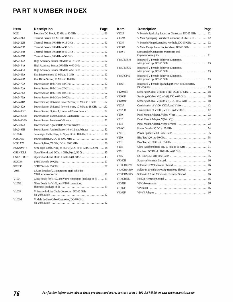
For further information about these products and more, contact us at 1-800-ANRITSU or visit www.us.anritsu.com76
PART NUMBER INDEX
K261 Precision DC Block, 50 kHz to 40 GHz . . . . . . . . . . . . . . . . . . . . . 63
MA2421A Thermal Sensor, 0.1 MHz to 18 GHz . . . . . . . . . . . . . . . . . . . . . . . . 52
MA2422B Thermal Sensor, 10 MHz to 18 GHz . . . . . . . . . . . . . . . . . . . . . . . . 52
MA2423B Thermal Sensor, 10 MHz to 32 GHz . . . . . . . . . . . . . . . . . . . . . . . . 52
MA2424B Thermal Sensor, 10 MHz to 40 GHz . . . . . . . . . . . . . . . . . . . . . . . . 52
MA2425B Thermal Sensor, 10 MHz to 50 GHz . . . . . . . . . . . . . . . . . . . . . . . . 52
MA2442A High Accuracy Sensor, 10 MHz to 18 GHz . . . . . . . . . . . . . . . . . . . 52
MA2444A High Accuracy Sensor, 10 MHz to 40 GHz . . . . . . . . . . . . . . . . . . . 52
MA2445A High Accuracy Sensor, 10 MHz to 50 GHz . . . . . . . . . . . . . . . . . . . 52
MA2468A Fast Diode Sensor, 10 MHz to 6 GHz . . . . . . . . . . . . . . . . . . . . . . . 52
MA2469B Fast Diode Sensor, 10 MHz to 18 GHz . . . . . . . . . . . . . . . . . . . . . . 52
MA2472A Power Sensor, 10 MHz to 18 GHz . . . . . . . . . . . . . . . . . . . . . . . . . . 52
MA2473A Power Sensor, 10 MHz to 32 GHz . . . . . . . . . . . . . . . . . . . . . . . . . . 52
MA2474A Power Sensor, 10 MHz to 40 GHz . . . . . . . . . . . . . . . . . . . . . . . . . . 52
MA2475A Power Sensor, 10 MHz to 50 GHz . . . . . . . . . . . . . . . . . . . . . . . . . . 52
MA2481B Power Sensor, Universal Power Sensor, 10 MHz to 6 GHz . . . . . . 52
MA2482A Power Sensor, Universal Power Sensor, 10 MHz to 18 GHz . . . . .52
MA2480/01 Power Sensor, Option 1, Universal Power Sensor . . . . . . . . . . . . . . 52
MA2400/98 Power Sensor, Z540/Guide 25 Calibration . . . . . . . . . . . . . . . . . . . . 52
MA2400/99 Power Sensor, Premium Calibration . . . . . . . . . . . . . . . . . . . . . . . . . 52
MA2497A Power Sensor, Agilent (HP) Sensor adapter . . . . . . . . . . . . . . . . . . . 52
MA2499B Power Sensor, Anritsu Sensor 10 to 12 pin Adapter . . . . . . . . . . . . 52
N120-6 Semi-rigid Cable, N(m) to N(m), DC to 18 GHz, 15.2 cm . . . . . . . 18
N241A50 Power Splitter, N, DC to 3000 MHz . . . . . . . . . . . . . . . . . . . . . . . . . 56
N241A75 Power Splitter, 75 Ω N, DC to 3000 MHz . . . . . . . . . . . . . . . . . . . . 56
NS120MF-6 Semi-rigid Cable, N(m) to SMA(f), DC to 18 GHz, 15.2 cm . . . . 18
OSLN50LF Open/Short/Load, DC to 4 GHz, N(m), 50 Ω . . . . . . . . . . . . . . . . . 45
OSLNF50LF Open/Short/Load, DC to 4 GHz, N(f), 50 Ω . . . . . . . . . . . . . . . . . . 45
SC4734 SPDT Switch, 60 GHz . . . . . . . . . . . . . . . . . . . . . . . . . . . . . . . . . . . 57
SC6135 SPDT Switch, 65 GHz . . . . . . . . . . . . . . . . . . . . . . . . . . . . . . . . . . . . 57
V085 1.52 m length of 2.18 mm semi-rigid cable for V101 series connector . . . . . . . . . . . . . . . . . . . . . . . . . . . . . . . . . . . . 11
V100 Glass Beads for V102, and V103 connectors (package of 5) . . . . . 11
V100B Glass Beads for V102, and V103 connectors,Hermetic (package of 5) . . . . . . . . . . . . . . . . . . . . . . . . . . . . . . . . . . . 11
V101F V Female In-Line Cable Connector, DC-65 GHz for V085 cable . . . . . . . . . . . . . . . . . . . . . . . . . . . . . . . . . . . . . . . . . . . 12
V101M V Male In-Line Cable Connector, DC-65 GHz for V085 cable . . . . . . . . . . . . . . . . . . . . . . . . . . . . . . . . . . . . . . . . . . . 12
V102F V Female Sparkplug Launcher Connector, DC-65 GHz . . . . . . . . 12
V102M V Male Sparkplug Launcher Connector, DC-65 GHz . . . . . . . . . . 12
V103F V Female Flange Launcher, two-hole, DC-65 GHz . . . . . . . . . . . . 12
V103M V Male Flange Launcher, two-hole, DC-65 GHz . . . . . . . . . . . . . . 12
V110-1 Stress Relief Contact for Microstrip and Coplanar Waveguide . . . . . . . . . . . . . . . . . . . . . . . . . . . . . . . . . . . . . . 11
V115FMS10 Integrated V Female Solder-in Connector,with ground lip, DC-65 GHz . . . . . . . . . . . . . . . . . . . . . . . . . . . . . . . 13
V115FMS75 Integrated V Female Solder-in Connector,with ground lip, DC-65 GHz . . . . . . . . . . . . . . . . . . . . . . . . . . . . . . . 13
V115FCPW Integrated V Female Solder-in Connector,with ground lip, DC-65 GHz . . . . . . . . . . . . . . . . . . . . . . . . . . . . . . . 13
V116F Integrated V Female Sparkplug (Screw-in) Connector,DC-65 GHz . . . . . . . . . . . . . . . . . . . . . . . . . . . . . . . . . . . . . . . . . . . . . 13
V120MM Semi-rigid Cable, V(m) to V(m), DC to 67 GHz . . . . . . . . . . . . . . 18
V120FF Semi-rigid Cable, V(f) to V(f), DC to 67 GHz . . . . . . . . . . . . . . . . . 18
V120MF Semi-rigid Cable, V(m) to V(f), DC to 67 GHz . . . . . . . . . . . . . . . . 18
V202F Combination of V100, V102F, and V110-1 . . . . . . . . . . . . . . . . . . . 12
V202FB Combination of V100B, V102F, and V110-1 . . . . . . . . . . . . . . . . . . 12
V230 Panel Mount Adapter, V(f) to V(m) . . . . . . . . . . . . . . . . . . . . . . . . . 22
V232 Panel Mount Adapter, V(f) to V(f) . . . . . . . . . . . . . . . . . . . . . . . . . . . 22
V234 Panel Mount Adapter, V(m) to V(m) . . . . . . . . . . . . . . . . . . . . . . . . 22
V240C Power Divider, V, DC to 65 GHz . . . . . . . . . . . . . . . . . . . . . . . . . . . 54
V241C Power Splitter, V, DC to 65 GHz . . . . . . . . . . . . . . . . . . . . . . . . . . . . 55
V250 Bias Tee, V, 0.1 to 60 GHz . . . . . . . . . . . . . . . . . . . . . . . . . . . . . . . . . 58
V251 Bias Tee, V, 100 kHz to 65 GHz . . . . . . . . . . . . . . . . . . . . . . . . . . . . 59
V255 Ultra-Wideband Bias Tee, 50 kHz to 65 GHz . . . . . . . . . . . . . . . . . 61
V261 Precision DC Block, 100 kHz to 65 GHz . . . . . . . . . . . . . . . . . . . . . 63
V265 DC Block, 50 kHz to 65 GHz . . . . . . . . . . . . . . . . . . . . . . . . . . . . . . 65
VP100B Screw-in Hermetic Shroud . . . . . . . . . . . . . . . . . . . . . . . . . . . . . . . . . 16
VP100BCPW Solder-in CPW Hermetic Shroud . . . . . . . . . . . . . . . . . . . . . . . . . . . 16
VP100BMS10 Solder-in 10 mil Microstrip Hermetic Shroud . . . . . . . . . . . . . . . . . 16
VP100BMS75 Solder-in 7.5 mil Microstrip Hermetic Shroud . . . . . . . . . . . . . . . . 16
VP100BNL No Lip Hermetic Shroud . . . . . . . . . . . . . . . . . . . . . . . . . . . . . . . . . . 16
VP101F VP Cable Adapter . . . . . . . . . . . . . . . . . . . . . . . . . . . . . . . . . . . . . . . . 16
VP102F VP Bullet . . . . . . . . . . . . . . . . . . . . . . . . . . . . . . . . . . . . . . . . . . . . . . . 16
VP103F VP-VF Adapter . . . . . . . . . . . . . . . . . . . . . . . . . . . . . . . . . . . . . . . . . . 16
Item Description Page Item Description Page

For further information about these products and more, contact us at 1-800-ANRITSU or visit www.us.anritsu.com
POWER CONVERSION TABLE
Power (dBm) P (mW) Volts ms into 50 Ω Volts Peak Volts
Peak to Peak
-60 0.00000100 0.000224 0.000316 0.00063
-59 0.00000126 0.000251 0.000355 0.00071
-58 0.00000158 0.000282 0.000398 0.00080
-57 0.00000200 0.000316 0.000447 0.00089
-56 0.00000251 0.000354 0.000501 0.00100
-55 0.00000316 0.000398 0.000562 0.00112
-54 0.00000398 0.000446 0.000631 0.00126
-53 0.00000501 0.000501 0.000708 0.00142
-52 0.00000631 0.000562 0.000794 0.00159
-51 0.00000794 0.000630 0.000891 0.00178
-50 0.00000100 0.000707 0.001000 0.00200
-49 0.00000126 0.000793 0.001122 0.00224
-48 0.00000158 0.000890 0.001259 0.00252
-47 0.00000200 0.00100 0.001413 0.00283
-46 0.00000251 0.00112 0.001585 0.00317
-45 0.00000316 0.00126 0.001778 0.00356
-44 0.00000398 0.00141 0.001995 0.00399
-43 0.00000501 0.00158 0.002239 0.00448
-42 0.00000631 0.00178 0.002512 0.00502
-41 0.00000794 0.00199 0.002818 0.00564
-40 0.00000100 0.00224 0.003162 0.00632
-39 0.00000126 0.00251 0.003548 0.00710
-38 0.00000158 0.00282 0.003981 0.00796
-37 0.00000200 0.00316 0.004467 0.00893
-36 0.00000251 0.00354 0.005012 0.0100
-35 0.00000316 0.00398 0.005623 0.0112
-34 0.00000398 0.00446 0.006310 0.0126
-33 0.00000501 0.00501 0.007079 0.0142
-32 0.00000631 0.00562 0.007943 0.0159
-31 0.00000794 0.00630 0.008913 0.0178
-30 0.0010 0.00707 0.010000 0.0200
-29 0.0013 0.00793 0.011220 0.0224
-28 0.0016 0.00890 0.012589 0.0252
27 0.0020 0.00999 0.014125 0.0283
-26 0.0025 0.01121 0.015849 0.0317
-25 0.0032 0.01257 0.017783 0.0356
-24 0.0040 0.01411 0.019953 0.0399
-23 0.0050 0.01583 0.022387 0.0448
-22 0.0063 0.01776 0.025119 0.0502
-21 0.0079 0.01993 0.028184 0.0564
-20 0.0100 0.02236 0.031623 0.0632
-19 0.0126 0.02509 0.035481 0.0710
-18 0.0158 0.02815 0.039811 0.0796
-17 0.0200 0.03159 0.044668 0.0893
-16 0.0251 0.03544 0.050119 0.1002
-15 0.0316 0.03976 0.056234 0.1125
-14 0.0398 0.04462 0.063096 0.1262
-13 0.0501 0.05006 0.070795 0.1416
-12 0.0631 0.05617 0.079433 0.1589
-11 0.0794 0.06302 0.089125 0.1783
-10 0.1000 0.07071 0.100000 0.2000
Power (dBm) P (mW) Volts ms into 50 Ω Volts Peak Volts
Peak to Peak
–9 0.1259 0.07934 0.112 0.2244
-8 0.1585 0.08902 0.126 0.2518
-7 0.1995 0.09988 0.141 0.2825
-6 0.2512 0.11207 0.158 0.3170
-5 0.3162 0.12574 0.178 0.3557
-4 0.3981 0.14109 0.200 0.3991
-3 0.5012 0.15830 0.224 0.4477
-2 0.6310 0.17762 0.251 0.5024
-1 0.7943 0.19929 0.282 0.5637
0 1.0000 0.22361 0.316 0.6325
1 1.259 0.25089 0.355 0.7096
2 1.585 0.28150 0.398 0.7962
3 1.995 0.31585 0.447 0.8934
4 2.512 0.35439 0.501 1.0024
5 3.162 0.39764 0.562 1.1247
6 3.981 0.44615 0.631 1.2619
7 5.012 0.50059 0.708 1.4159
8 6.310 0.56167 0.794 1.5887
9 7.943 0.63021 0.891 1.7825
10 10.000 0.70711 1.000 2.0000
11 12.589 0.79339 1.122 2.2440
12 15.849 0.89019 1.259 2.5179
13 19.953 0.99881 1.413 2.8251
14 25.119 1.12069 1.585 3.1698
15 31.623 1.25743 1.778 3.5566
16 39.811 1.41086 1.995 3.9905
17 50.119 1.58301 2.239 4.4774
18 63.096 1.77617 2.512 5.0238
19 79.433 1.99290 2.818 5.6368
20 100.000 2.23607 3.162 6.3246
21 125.893 2.50891 3.548 7.0963
22 158.489 2.81504 3.981 7.9621
23 199.526 3.15853 4.467 8.9337
24 251.189 3.54393 5.012 10.0237
25 316.228 3.97635 5.623 11.2468
26 398.107 4.46154 6.310 12.6191
27 501.187 5.00593 7.079 14.1589
28 630.957 5.61675 7.943 15.8866
29 794.328 6.30210 8.913 17.8250
30 1000.000 7.07107 10.000 20.0000
31 1258.925 7.93387 11.220 22.4404
32 1584.893 8.90195 12.589 25.1785
33 1995.262 9.98815 14.125 28.2508
34 2511.886 11.20689 15.849 31.6979
35 3162.278 12.57433 17.783 35.5656
36 3981.072 14.10864 19.953 39.9052
37 5011.872 15.83015 22.387 44.7744
38 6309.573 17.76172 25.119 50.2377
39 7943.282 19.92898 28.184 56.3677
40 10000.000 22.36068 31.623 63.2456
41 12589.254 25.08910 35.481 70.9627

©Anritsu, September 2002; Made in U.S.A.11410-00235, Rev: C
Data subject to change without noticePrecision RF & Microwave Components Catalog
Sales Centers:US (800) ANRITSUCanada (800) ANRITSUSouth America 55 (21) 286-9141Europe 44 (01582) 433433Japan 81 (03) 3446-1111Asia-Pacific 65-2822400
ANRITSU Corporation Head OfficeTokyo, Japan
Microwave Measurements Division 490 Jarvis Drive
Morgan Hill, CA 95037-2809http://www.us.anritsu.com
FAX (408) 778-0239
K and V Connectors are registered trademarks of Anritsu Company. All trademarks are registered trademarks of their respective companies.
BRAZIL
ANRITSU ELETRÔNICA LTDA.Praia de Botafogo 440, Sala 2401-Bota22250-040, Rio de Janeiro, RJ, BrazilPhone: +55-21-527-6922Fax: +55-21-537-1456
CANADA
ANRITSU ELECTRONICS LTD. 700 Silver Seven Road, Suite 120 Kanata, OntarioCanada, K2V 1C3Phone: +1-613-591-2003Fax: +1-613-591-1006
FRANCE
ANRITSU S.A.9, Avenue du Québec ZA de Courtabœuf 191951 Les Ulis Cedex, FrancePhone: +33-1-60-92-15-50Fax: +33-1-64-46-10-65
GERMANY
ANRITSU GMBHGrafenberger Allee 54-56, D-40237 Düsseldorf, GermanyPhone: +49-211-96855-35Fax: +49-211-96855-55
ITALY
ANRITSU S.P.A.Via Elio Vittorini, 129, 00144 Roma, ItalyPhone: +39-06-509-9711Fax: +39-06-502-2425
JAPAN
ANRITSU CORPORATION5-10-27 Minami-AzabuMinato-ku, Tokyo 106-8570, JapanPhone: +81-3-3446-1111Fax: +81-3-3442-0235
SWEDEN
ANRITSU A.B.Botvid Center Fittja Backe 1-3, 145 84, Stockholm, SwedenPhone: +46-8-534-707-00Fax: +46-8-534-707-30
UNITED KINGDOM
ANRITSU LTD.200 Capability Green, Luton, Bedfordshire, LU1 3LU, United KingdomPhone: +44-1582-433200Fax: +44-1582-731303
UNITED STATES
ANRITSU COMPANY 1155 East Collins Blvd.,Richardson, TX 75081, U.S.A.Phone: (800)-ANRITSU (267-4878)Fax: (972)-671-1877
ANRITSU Company FactoryMorgan Hill, California,U.S.A.
ANRITSU Corporation FactoryAtsugi, Kanagawa, Japan
For more information call your Regional Sales Office or visit www.us.anritsu.com.
SALES OFFICES
ANRITSU North AmericanOperations HeadquartersRichardson, Texas, U.S.A.