rf and optical communications: a comparison of high · pdf file · 2018-01-26rf and...
TRANSCRIPT

W. Dan Williams Glenn Research Center, Cleveland, Ohio
Michael Collins ASRC Management Services, Reston, Virginia
Don M. Boroson MIT Lincoln Laboratory, Lexington, Massachusetts
James Lesh and Abihijit Biswas Jet Propulsion Laboratory, Pasadena, California
Richard Orr and Leonard Schuchman SATEL LLC, Rockville, Maryland
O. Scott Sands Glenn Research Center, Cleveland, Ohio
RF and Optical Communications: A Comparison of High Data Rate Returns From Deep Space in the 2020 Timeframe
NASA/TM—2007-214459
March 2007
K000083
An Erratum was added to this report January 2018.
https://ntrs.nasa.gov/search.jsp?R=20070017310 2018-05-19T01:49:10+00:00Z
NASA STI Program . . . in Profile
Since its founding, NASA has been dedicated to the advancement of aeronautics and space science. The NASA Scientific and Technical Information (STI) Program plays a key part in helping NASA maintain this important role.
The NASA STI Program operates under the auspices of the Agency Chief Information Officer. It collects, organizes, provides for archiving, and disseminates NASA’s STI. The NASA STI Program provides access to the NASA Technical Report Server—Registered (NTRS Reg) and NASA Technical Report Server—Public (NTRS) thus providing one of the largest collections of aeronautical and space science STI in the world. Results are published in both non-NASA channels and by NASA in the NASA STI Report Series, which includes the following report types: • TECHNICAL PUBLICATION. Reports of
completed research or a major significant phase of research that present the results of NASA programs and include extensive data or theoretical analysis. Includes compilations of significant scientific and technical data and information deemed to be of continuing reference value. NASA counter-part of peer-reviewed formal professional papers, but has less stringent limitations on manuscript length and extent of graphic presentations.
• TECHNICAL MEMORANDUM. Scientific
and technical findings that are preliminary or of specialized interest, e.g., “quick-release” reports, working papers, and bibliographies that contain minimal annotation. Does not contain extensive analysis.
• CONTRACTOR REPORT. Scientific and technical findings by NASA-sponsored contractors and grantees.
• CONFERENCE PUBLICATION. Collected papers from scientific and technical conferences, symposia, seminars, or other meetings sponsored or co-sponsored by NASA.
• SPECIAL PUBLICATION. Scientific,
technical, or historical information from NASA programs, projects, and missions, often concerned with subjects having substantial public interest.
• TECHNICAL TRANSLATION. English-
language translations of foreign scientific and technical material pertinent to NASA’s mission.
For more information about the NASA STI program, see the following:
• Access the NASA STI program home page at http://www.sti.nasa.gov
• E-mail your question to [email protected] • Fax your question to the NASA STI
Information Desk at 757-864-6500
• Telephone the NASA STI Information Desk at 757-864-9658 • Write to:
NASA STI Program Mail Stop 148 NASA Langley Research Center Hampton, VA 23681-2199

W. Dan Williams Glenn Research Center, Cleveland, Ohio
Michael Collins ASRC Management Services, Reston, Virginia
Don M. Boroson MIT Lincoln Laboratory, Lexington, Massachusetts
James Lesh and Abihijit Biswas Jet Propulsion Laboratory, Pasadena, California
Richard Orr and Leonard Schuchman SATEL LLC, Rockville, Maryland
O. Scott Sands Glenn Research Center, Cleveland, Ohio
RF and Optical Communications: A Comparison of High Data Rate Returns From Deep Space in the 2020 Timeframe
NASA/TM—2007-214459
March 2007
K000083
An Erratum was added to this report January 2018.
National Aeronautics andSpace Administration
Glenn Research Center Cleveland, Ohio 44135
Prepared for the 12th Ka and Broadband Communications Conference cosponsored by Alcatel Alenia Space, CPI Satcom Division, ESA, Finmeccanica, Galileo Industries, MARS, Space Engineering, and Telespazio Naples, Italy, September 27–29, 2006

Available from
Trade names and trademarks are used in this report for identification only. Their usage does not constitute an official endorsement, either expressed or implied, by the National Aeronautics and
Space Administration.
Level of Review: This material has been technically reviewed by technical management.
This report contains preliminary findings, subject to revision as analysis proceeds.
NASA STI ProgramMail Stop 148NASA Langley Research CenterHampton, VA 23681-2199
National Technical Information Service5285 Port Royal RoadSpringfield, VA 22161
703-605-6000
This report is available in electronic form at http://www.sti.nasa.gov/ and http://ntrs.nasa.gov/
Erratum
Issued January 2018 for
NASA/TM—2007-214459RF and Optical Communications: A Comparison of High Data Rate Returns From Deep Space in the 2020 Timeframe
W. Dan Williams, Michael Collins, Don M. Boroson, James Lesh, Abihijit Biswas,Richard Orr, Leonard Schuchman, and O. Scott Sands
March 2007
Table 2; 0.38 AU column; 1000 Mbps row: Replace power value to read 195 W.

NASA/TM—2007-214459 1
RF and Optical Communications: A Comparison of High Data Rate Returns from Deep Space in the 2020 Timeframe
W. Dan Williams National Aeronautics and Space Administration
Glenn Research Center Cleveland, Ohio 44135
Michael Collins ASRC Management Services
Reston, Virginia 20190
Don M. Boroson MIT Lincoln Laboratory
Lexington, Massachusetts 02420
James Lesh and Abihijit Biswas National Aeronautics and Space Administration
Jet Propulsion Laboratory Pasadena, California 91109
Richard Orr and Leonard Schuchman SATEL LLC
Rockville, Maryland 20850
O. Scott Sands National Aeronautics and Space Administration
Glenn Research Center Cleveland, Ohio 44135
Abstract
As NASA proceeds with plans for increased science data return and higher data transfer capacity for science missions, both RF and optical communications are viable candidates for significantly higher-rate communications from deep space to earth. With the inherent advantages, smaller apertures and larger bandwidths, of optical communications, it is reasonable to expect that at some point in time and combination of increasing distance and data rate, the rapidly emerging optical capabilities would become more advantageous than the more mature and evolving RF techniques. This paper presents a comparison of the burden to a spacecraft by both RF and optical communications systems for data rates of 10, 100, and 1000 Mbps and large distances. Advanced technology for RF and optical communication systems have been considered for projecting capabilities in the 2020 timeframe. For the comparisons drawn, the optical and RF ground terminals were selected to be similar in cost. The RF system selected is composed of 45 12-meter antennas, whereas the selected optical system is equivalent to a 10-meter optical telescope. Potential differences in availability are disregarded since the focus of this study is on spacecraft mass and power burden for high-rate mission data, under the assumption that essential communications will be provided by low-rate, high availability RF. For both the RF and optical systems, the required EIRP, for a given data rate and a given distance, was achieved by a design that realized the lowest possible communications subsystem mass (power + aperture) consistent with achieving the lowest technology risk. A key conclusion of this paper is that optical communications has great potential for high data rates and distances of 2.67 AU and beyond, but requires R&D and flight demonstrations to prove out technologies.
1. Introduction
As the National Aeronautics and Space Administration (NASA) plans to carry out the Vision for Space Exploration (VSE) [Ref. 1] of returning humans to the moon followed by a human visit to Mars, along with

NASA/TM—2007-214459 2
the continuation of data-intensive earth and space science missions, high data rates become very important to the future of the agency. Though communication systems can be characterized by numerous parameters, e.g., data rate, availability, delay, quality of service, etc., it is data rate that tends to evoke discussion. As science and technological programs embark on this new frontier, downlink data rate capabilities of over 100 Mbps (megabits per second) from Mars have been discussed [Ref. 2], and even higher rate communications may be desirable. RF communications and free-space optical communications are the two possible approaches to meeting the future needs.
The history of the two technologies and the investments made are very different. RF is the most widely used communication medium for space applications. Its technological development spans over 100 years, and its operational aspects are well understood. By comparison, NASA started investigating optical systems in the early 1960s, shortly after the development of the first lasers. By the late 1980’s/early 1990’s, serious investment in optical systems began to pay off, and currently, optical systems are being demonstrated in near-earth applications. Thus, in comparing RF and optical communications for the challenging regime of distance measured in astronomical units, typical of Mars and beyond, NASA’s Space Communications Architecture Working Group (SCAWG) has undertaken the challenge to compare a rapidly emerging capability with a more mature, evolutionarily advancing one. The technology maturity and risks, as well as each system’s unique advantages and disadvantages, result in a complex comparison. This study bases its comparisons deep space return links, whose capacity demands will greatly those of uplinks, even for human exploration missions. 2. Background The study reported here is an effort to compare RF and optical systems for deep-space applications and is primarily focused on answering the question, “Under what conditions should it be desirable to transition from RF to optical communications for high-capacity, deep space communications?” The results show that each system provides advantages in particular regimes, and the design choice should be viewed with mission specificity in determining a course to follow. Optical systems have the advantage of extremely broad, unregulated bandwidth compared to RF systems. At Ka-band frequencies of 32 or 37-38 GHz, bandwidth is typically 500 MHz. For optical systems at 1.55 µm, the bandwidth may be 1000 times larger, allowing optical systems to carry substantially more information. For RF systems to compete in a bandwidth-constrained environments they must resort to bandwidth-efficient modulation for data rates above 1 Gbps, which is neither power- nor mass-efficient for the transmitting terminal. Optical systems typically would have smaller receive apertures and lower power efficient transmitters and receivers. While RF systems do suffer from atmospheric attenuation due to weather, especially at Ka-band and above, they have the capability of penetrating cloud cover, whereas optical systems do not. Mars Laser Communications Demonstration (MLCD) Terminal, planned for a 2009 launch on the Mars Telecomm Orbiter (MTO) but subsequently cancelled, is used as an initial optical design basis in this study. MLCD was planned for less than 90 kg with dual transmitters, less than 200 W power draw and operating at 55 Mbps at Mars minimum distance (0.38 AU). The RF design is based on a simple component approach and years of RF experience. Making assumptions regarding the technology, maturity, and risk strongly impacts the outcome of the study and results in large uncertainties. 3. Assumptions Due to the numerous variables involved, several assumptions were made in this study:
1. Technology would be well developed by 2015, allowing for 2020 operational system deployment. 2. The earth-end receivers are located on the earth’s surface and are fixed to an equivalent aperture
size based on approximately equal initial purchase cost estimates for both systems. Due to the significant space loss from Mars or beyond, the optical photon flux and the RF power density are so low that a large aperture aboard the spacecraft is required for data rates above 100 Mbps. Because flying a 10-m diameter optical apertures or a 100-m diameter RF antenna is costly and technically challenging, the authors chose to assume ground-based assets for the receive systems. These are described in greater detail subsequently.
3. One link at a time is considered rather than multiple links which are possible for either system.

NASA/TM—2007-214459 3
4. User burden on the spacecraft (transmit aperture, power and mass) was calculated based on: (a)data rates of 10, 100, and 1000 Mbps; (b) distances from earth ranging from 0.38 to 30 AU, and(c) a measure of technological complexity (as shown in Figure 1).
4. System Descriptions
Ground-Based Receivers
Normalization of the RF and optical receiver sites is based on cost. Large apertures may be realized by large monolithic antennas (telescopes) or arrays of smaller antennas (telescopes). The baseline optical terminal is assumed to be equivalent to a 10-meter system, and the RF ground terminal is assumed to be an array of 45 12-meter antennas (roughly equivalent to five 34-meter antennas). Either capability is estimated to cost about $40M.
Spacecraft Terminals
Both the RF and optical designs assume a body-mounted antenna. Over the synodic period of the earth-Mars system (2.17 yr) the earth appears over a ±45o angle relative to the Sun-Mars axis. The spacecraft continually points its antenna toward earth (coarse pointing). But a mechanism to maintain pointing to fine tolerances may be required for either package. Fine pointing for optical links is very difficult due to the small divergence of the optical beam. A special inertial reference unit was planned for the optical communications terminal on MLCD. The concept has been demonstrated in the laboratory but not in flight. The large RF antennas required for high data rates may require fine pointing beyond that supplied by spacecraft pointing.
To maintain a low antenna pointing loss the spacecraft must be pointed with small error. Large antennas exacerbate the pointing problem as they have smaller beam divergence angles, and thus pointing loss becomes more sensitive to pointing error as the diameter increases. [Ref. 6] The mass associated with fine pointing for optical communications is included in the analysis, but the comparable mass for the RF antenna is expected to be small and is neglected.
RF Terminal
The RF terminal analysis assumes high power transmitters, lightweight antennas and modulation techniques comparable to the best available today. Careful selection of a large area antenna and high power transmitter will enable 1 Gbps data rates from Martian distances. [Ref 2-6] The power transmitter is based on technology being space qualified today. Using waveguide combining techniques with 180-250 W TWTAs, it is very possible to increase transmitter power to 1 kW.
Antenna technology will prove more of a challenge than will the transmitter. Operational 5-m Ka-band reflector antennas with areal mass densities up to 2 kg/m2 and large mesh antennas of areal density 1 kg/m2 are being flown today. There are three Thuraya satellites used for mobile phones employing 12-m antennas at L-band, the first of which has been in operation for about six years. Extrapolation to Ka-band appears to be straightforward. Should the efficiency of the mesh antennas not meet specifications, there are at least two alternatives. Inflatable antennas with areal densities less than 1 kg/m2 are being developed and have been demonstrated with good efficiencies up to 4 x 6 m. A second approach is a hybrid antenna with a fixed center section and an inflatable outer ring.
Optical Terminal
The optical communications terminal is based on technologies extrapolated from those developed for MLCD [Ref 8]. Pulse Position Modulation, created with a Master Oscillator Power Amplifier (MOPA) architecture, and protective membrane solar rejection filters that cover telescope apertures and to promote thermally constant operation are assumed. The telescope would be a reflector design, with a lightweight glass primary mirror. Beam stabilization requires a combination of vibration isolation, an optical reference, and an active steering mechanism. MLCD used heritage vibration isolators that also lowered the launch loads. As it is difficult to deliver high optical power to deep space through the earth’s atmosphere, MLCD took as its optical reference a combination of the earth image, (monitored by a focal

NASA/TM—2007-214459 4
plane array FPA) and a locally-generated, inertially-stabilized laser (the MIRU for Magneto-hydrodynamic Inertial Reference Unit or earlier Miniature Inertial Reference Unit), monitored on a quadrant detector. For telescopes larger than 30 cm (MLCD), a lighter structure and vibration isolator are assumed, more directly mounted to the spacecraft, with a slightly higher bandwidth tracking mirror. Point-ahead is calculated based on position and attitude knowledge of the spacecraft as well as knowledge of the position of the ground site. The Point Ahead Mechanism output is monitored and calibrated with a small amount of transmitter light sent to the earth-monitoring FPA. The transmitter is a MOPA architecture, with the entire system at wavelength 1.55 microns. 5. Approach As discussed in Ref. 7, for a given EIRP requirement at the spacecraft, the combined mass of the antenna and power subsystems is minimized if the antenna system mass equals the power system mass.1 However, this technique does not consider the “technological risk” of the resulting design, i.e., the probability of success given a normal research and development effort. In this study, for a given EIRP, the solution that provides the minimum mass for the minimum risk is chosen.
Table 1: Technical Risk in Terms of Complexity Factor
Complexity
Level Color Code Probability of Success for a Normal R&D Effort
1 low 99 2 moderate 90 3 moderate to difficult 80 4 difficult 50 5 very difficult 10-20
Curves of Constant EIRPVery Difficult
Difficult
Moderate to Difficult
Moderate
Low
Curves of Constant EIRPVery Difficult
Difficult
Moderate to Difficult
Moderate
Low
Very Difficult
Difficult
Moderate to Difficult
Moderate
Low
Curves of Constant EIRP (increasing)
0
20
40
60
80
100
120
140
160
0 30 60 90 120 150 180 210 240 270 300 330 360
Aperture Diameter (cm)
Opt
ical
Pow
er (W
)
Very DifficultDifficult
Moderate to DifficultModerate
Low
Curves of Constant EIRP (increasing)
0
20
40
60
80
100
120
140
160
0 30 60 90 120 150 180 210 240 270 300 330 360
Aperture Diameter (cm)
Opt
ical
Pow
er (W
)
Very DifficultDifficult
Moderate to DifficultModerate
Low
Very DifficultDifficult
Moderate to DifficultModerate
Low
Figure 1: Technology Complexity Levels for RF (left) and Optical (right) Communication Systems.
It is desirable to have a complexity factor no greater than level 3. This means that it is desirable to keep RF power below 1 kW and antenna diameter below 14 m. For the optical terminals, the optical power should be kept below 75 W and aperture diameter below 200 cm. 6. Results Distance and data rate fix the required EIRP. As shown in Table 2, as either distance or data rate increases, complexity will increase. For example, at 2.67 AU, the complexity level remains at level 1 as data rate increases up to 10 Mbps. From 50-500 Mbps, the complexity value is 2; it reaches 3 at 1 Gbps, 4 at 2.5 Gbps, and 5 beyond that. At 1 Gbps, a 9-m antenna and 1 kW of power is required. Also it should
1 The supporting analysis assumes specific mass models for the antenna and power system. Antenna mass is taken to be proportional to aperture area, and power mass is proportional to RF power.

NASA/TM—2007-214459 5
also be noted that the complexity level is driven by the power since a 9-meter antenna has a lower complexity value, 2. A similar table, not shown here, has been generated for an assumed antenna density of 2 kg/m2. The paired antenna and power values remain approximately the same. Table 2 shows the values of aperture and power for both the RF and optical systems as a function of technology complexity factor (low complexity-low risk).
Figure 2 shows the values of RF and optical mass vs. distance and data rate. With the distance fixed at 2.67 AU, the RF mass range is 100-175 kg for data rate 1 Gbps; the corresponding optical mass is 42 kg. The RF mass range for 100 Mbps is 35-51 kg and for 10 Mbps it is 12-16kg. In the latter two cases the corresponding optical masses are 26 and 14 kg, respectively. As distance increases, the difference between RF mass and optical mass requirements increases at all data rates.
From Figure 3, the RF power requirement is significantly greater than that for optical systems, when normalized for distance and data rate. A more graphic comparison is given in Figures 4 and 5. The RF-to-optical mass ratio at 1 Gbps is 2.5 for the maximum Mars distance and continues to grow beyond Mars (Figure 4). If a 1-kg/m² antenna density can be achieved, RF remains attractive for distances out to 2.67 AU, and at 10 Mbps does not double until the distance is 30 AU.
Table 2: RF Power and Antenna Diameter (antenna mass density = 1 kg/m²) (top) and Optical Power and Telescope Diameter (bottom) as a Function of Data Rate, Complexity and Distance.
Data Rate 1 kg/m2
Mbps 0.38 AU 2.67 AU 8.44 AU 26.7 AU 84.4 AU4000 12.8 m, 2.5 kW3000 9 m,1 kW2500 6.5 m, 0.97kW 18.3 m, 2.5 kW2250 12.8 m, 2.5 kW1000 2.9 m,19 W 9 m, 1 kW 18.3 m, 2.5 kW
500 2.5 m,131 W 6.5 m, 0.97 kW 12.8 m, 2.5 kW100 1.6 m, 64 W 4.2 m, 464 W 9 m, 1 kW 18.3 m, 2.5 kW
50 1.3 m, 48 W 3.5 m, 335 W 6.5 m, 0.97 kW 12.8 m, 2.5 kW10 0.9 m, 20 W 2.3 m, 155 4.2 m, 464 W 9 m, 1 kW 18.3 m, 2.5 kW
5 0.7 m, 17 W 1.7 m, 142 W 3.5 m, 335 W 6.5 m, 0.97 kW 12.8 m, 2.5 kW1 1.3 m, 48 W 2.3 m, 155 4.2 m, 464 W 9 m, 1 kW
0.5 1.3 m, 24 W 1.7 m, 142 W 3.5 m, 335 W 6.5 m, 0.97 kW0.1 0.8 m, 17 W 1.3 m, 48 W 2.3 m, 155 4.2 m, 464 W
0.05 1.3 m, 24 W 1.7 m, 142 W 3.5 m, 335 W0.01 0.8 m, 17 W 1.3 m, 48 W 2.3 m, 155
0.005 1.3 m, 24 W 1.7 m, 142 W0.001 0.8 m, 17 W 1.3 m, 48 W
0.0005 1.3 m, 24 W0.0001 0.8 m, 17 W
Distance (AU) Diam (cm) Opt Pwr (W) Diam (cm) Opt Pwr (W) Diam (cm) Opt Pwr (W)
1 26 10 11 5 7.5 12.68 50 19 26 7 14 26.47 95 30 48 12 22 511.09 130 50 65 20 31 1021.1 200 75 106 30 50 1350.36 350 160 200 50 100 23
1000 Mbps 100 Mbps 10 Mbps

NASA/TM—2007-214459 6
RF and Optical Mass as a Function of Distance for 10, 100, & 1000 Mbps in the 2020 Timeframe- RF Mass includes the antenna, EPC, radiator, and electronics
- Optical includes daytime numbers for telescope, mount, radiator, and electronics
1.0
10.0
100.0
1000.0
0.1 1 10 100Distance (AU)
Mas
s (K
g)
Optical 10 Mbps Optical 100 Mbps Optical 1 Gbps RF 10 Mbps - 1kg/m2 RF 100 Mbps - 1kg/m2RF 1 Gbps - 1kg/m2 RF 10 Mbps - 2kg/m2 RF 100 Mbps - 2kg/m2 RF 1 Gbps - 2kg/m2
Low Very Difficult Difficult Moderate To Difficult Moderate
Mars Jupiter Saturn Uranus Pluto
Figure 2: The RF Mass and Optical Mass are given as a function of distance and data rate.
Total Power as a Function of Distance for RF and Optical for 10 Mbps, 100 Mbps, and 1 Gbps
1
10
100
1000
10000
0.1 1 10 100
Distance (AU)
Pow
er (W
)
10 Mbps
100 Mbps
1 Gbps
Mars Jupiter Saturn Uranus Pluto
Low Very Difficult Difficult Moderate To Difficult Moderate
RF - Solid LineOptical - Dashed Line
Figure 3: Total Power as a Function of Distance for RF and Optical Systems in the 2020 Timeframe.

NASA/TM—2007-214459 7
Figure 5 presents the power ratio for all three data rates. It becomes quite clear that there is a substantial savings in power in using optical systems compared to RF.
Ratio of RF Mass/Optical Mass as a function of Distance for Various Data Rates- RF Antenna mass density of 1 kg/m2
- Optical mass is minimum daytime
0
0.5
1
1.5
2
2.5
3
3.5
4
0 5 10 15 20 25 30
Distance (AU)
MRF
/MO
ptic
al
10 Mbps100 Mbps1000 Mbps
Figure 4: Ratio of RF to Optical Mass as a Function of Distance for Various Data Rates in the 2020 Timeframe.
Ratio of Total RF Spacecraft Power/Total Optical Power as a Function of Distance for Various Data Rates
- RF Antenna Mass density is 1 kg/m2 - Optical mass is minimum daytime
0
5
10
15
20
25
0 5 10 15 20 25 30
Distance (AU)
P RF/
P Opt
ical
10 Mbps100 Mbps1000 Mbps
Figure 5: Ratio of RF to Optical Total Spacecraft Power as a Function of Distance for Various Data Rates in the 2020 Timeframe
NASA/TM—2007-214459 8
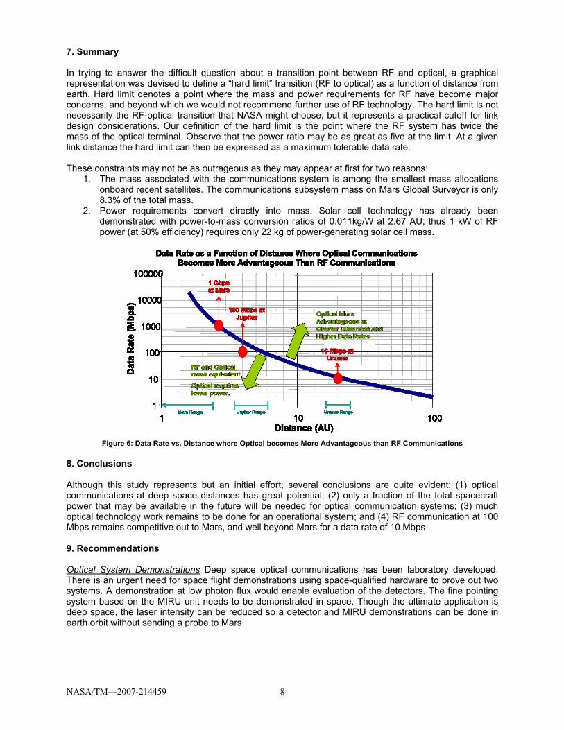
7. Summary
In trying to answer the difficult question about a transition point between RF and optical, a graphical representation was devised to define a “hard limit” transition (RF to optical) as a function of distance from earth. Hard limit denotes a point where the mass and power requirements for RF have become major concerns, and beyond which we would not recommend further use of RF technology. The hard limit is not necessarily the RF-optical transition that NASA might choose, but it represents a practical cutoff for link design considerations. Our definition of the hard limit is the point where the RF system has twice the mass of the optical terminal. Observe that the power ratio may be as great as five at the limit. At a given link distance the hard limit can then be expressed as a maximum tolerable data rate.
These constraints may not be as outrageous as they may appear at first for two reasons: 1. The mass associated with the communications system is among the smallest mass allocations
onboard recent satellites. The communications subsystem mass on Mars Global Surveyor is only 8.3% of the total mass.
2. Power requirements convert directly into mass. Solar cell technology has already beendemonstrated with power-to-mass conversion ratios of 0.011kg/W at 2.67 AU; thus 1 kW of RF power (at 50% efficiency) requires only 22 kg of power-generating solar cell mass.
Figure 6: Data Rate vs. Distance where Optical becomes More Advantageous than RF Communications
8. Conclusions
Although this study represents but an initial effort, several conclusions are quite evident: (1) optical communications at deep space distances has great potential; (2) only a fraction of the total spacecraft power that may be available in the future will be needed for optical communication systems; (3) much optical technology work remains to be done for an operational system; and (4) RF communication at 100 Mbps remains competitive out to Mars, and well beyond Mars for a data rate of 10 Mbps
9. Recommendations
Optical System Demonstrations Deep space optical communications has been laboratory developed. There is an urgent need for space flight demonstrations using space-qualified hardware to prove out two systems. A demonstration at low photon flux would enable evaluation of the detectors. The fine pointing system based on the MIRU unit needs to be demonstrated in space. Though the ultimate application is deep space, the laser intensity can be reduced so a detector and MIRU demonstrations can be done in earth orbit without sending a probe to Mars.

NASA/TM—2007-214459 9
The Need for A More Comprehensive Second Phase RF/Optics Study This first but important study has increased our understanding of where and when a transition from RF to optics should occur. Remaining issues include the following:
1. Availability. Due to earth weather susceptibility, optical communications availability suffers incomparison to RF. An attempt to normalize RF and optical designs in terms of availability will impact the number of ground terminals required, their operations, Life Cycle Costs and whether other lower data rate links are required. The question is significant in light of the potential development of both optical and RF arrays of receive apertures that can be allocated on demand to support multiple mission needs.
2. Total spacecraft payload. The total spacecraft payload comprises mission payloads, proximitypayloads, uplinks and high availability channels, e.g., TT&C. These are not independent. Their joint consideration raises questions such as, “How does a spacecraft with an optical high data rate link provide highly available lower rate data in a manner that minimizes mass? For example, a fully RF system can mix channels of various rates and availabilities, but this is perhaps not as simple for optics. Such questions must be addressed if the basis of comparison is to be broadened.
3. Continued RF research in lightweight antennas and power. Although recent work in lightweightantennas is quite exciting, a conservative view is taken in this study with regard to antenna mass density. Many researchers believe antenna densities less than 1kg/m² can be achieved by 2020. Lightweight TWT’s that can transmit 1 kW are on the horizon, with great potential for mass savings. Finally, major strides are now being made in solar power arrays that will yield panels producing much greater power per unit area than operationally exist today.
References
1. NASA’s Vision for Space Exploration (VSE) athttp://www.nasa.gov/pdf/55583main_vision_space_exploration2.pdf 2. NASA Space Communications and Navigation Architecture Recommendations for 2005-2030,available at https://www.spacecomm.nasa.gov/spacecomm/ 3. High Capacity Communications from Martian Distances, NASA TM214415, 2006.4. High Capacity Communications from Martian Distances: Spacecraft Design and Link Analysis, HemaliN. Vyas, et al., 12th Ka and Broadband Conference, September 2006. 5. High Capacity Communications from Martian Distances: Spacecraft Systems Engineering Trade Study,Michael Collins, et al., 12th Ka and Broadband Conference, September 2006. 6. High Capacity Communications from Martian Distances: Assessment of Spacecraft Pointing AccuracyCapabilities Required for Large Ka-Band Reflector Antennas, O. Scott Sands, et al., 12th Ka and Broadband Conference, September 2006. 7. Mars Exploration Deep Space Return Link Scenario and Transmit Operation System, Gary Noreen, etal., International Astronautical Congress, October 2005. 8. Overview of the Mars Laser Communications Demonstration Project, Bernard L. Edwards, et al., AIAASpace Conference, September, 2003.

This publication is available from the NASA Center for AeroSpace Information, 301–621–0390.
REPORT DOCUMENTATION PAGE
2. REPORT DATE
19. SECURITY CLASSIFICATION OF ABSTRACT
18. SECURITY CLASSIFICATIONOF THIS PAGE
Public reporting burden for this collection of information is estimated to average 1 hour per response, including the time for reviewing instructions, searching existing data sources,gathering and maintaining the data needed, and completing and reviewing the collection of information. Send comments regarding this burden estimate or any other aspect of thiscollection of information, including suggestions for reducing this burden, to Washington Headquarters Services, Directorate for Information Operations and Reports, 1215 JeffersonDavis Highway, Suite 1204, Arlington, VA 22202-4302, and to the Office of Management and Budget, Paperwork Reduction Project (0704-0188), Washington, DC 20503.
NSN 7540-01-280-5500 Standard Form 298 (Rev. 2-89)Prescribed by ANSI Std. Z39-18298-102
Form Approved
OMB No. 0704-0188
12b. DISTRIBUTION CODE
8. PERFORMING ORGANIZATIONREPORT NUMBER
5. FUNDING NUMBERS
3. REPORT TYPE AND DATES COVERED
4. TITLE AND SUBTITLE
6. AUTHOR(S)
7. PERFORMING ORGANIZATION NAME(S) AND ADDRESS(ES)
11. SUPPLEMENTARY NOTES
12a. DISTRIBUTION/AVAILABILITY STATEMENT
13. ABSTRACT (Maximum 200 words)
14. SUBJECT TERMS
17. SECURITY CLASSIFICATIONOF REPORT
16. PRICE CODE
15. NUMBER OF PAGES
20. LIMITATION OF ABSTRACT
Unclassified Unclassified
Technical Memorandum
Unclassified
National Aeronautics and Space AdministrationJohn H. Glenn Research Center at Lewis FieldCleveland, Ohio 44135–3191
1. AGENCY USE ONLY (Leave blank)
10. SPONSORING/MONITORINGAGENCY REPORT NUMBER
9. SPONSORING/MONITORING AGENCY NAME(S) AND ADDRESS(ES)
National Aeronautics and Space AdministrationWashington, DC 20546–0001
Available electronically at http://gltrs.grc.nasa.gov
March 2007
NASA TM—2007-214459K000083
E–15723-1
WBS 439432.07.04.03.01
15
RF and Optical Communications: A Comparison of High Data Rate ReturnsFrom Deep Space in the 2020 Timeframe
W. Dan Williams, Michael Collins, Don M. Boroson, James Lesh,Abihijit Biswas, Richard Orr, Leonard Schuchman, and O. Scott Sands
Spacecraft communication systems; Optical communications; RF communications
Unclassified -UnlimitedSubject Category: 17
As NASA proceeds with plans for increased science data return and higher data transfer capacity for science missions, both RF and optical
communications are viable candidates for significantly higher-rate communications from deep space to Earth. With the inherent advantages, smaller
apertures and larger bandwidths, of optical communications, it is reasonable to expect that at some point in time and combination of increasing distance
and data rate, the rapidly emerging optical capabilities would become more advantageous than the more mature and evolving RF techniques. This paper
presents a comparison of the burden to a spacecraft by both RF and optical communications systems for data rates of 10, 100, and 1000 Mbps and large
distances. Advanced technology for RF and optical communication systems have been considered for projecting capabilities in the 2020 timeframe. For
the comparisons drawn, the optical and RF ground terminals were selected to be similar in cost. The RF system selected is composed of forty-five 12-
meter antennas, whereas the selected optical system is equivalent to a 10-meter optical telescope. Potential differences in availability are disregarded
since the focus of this study is on spacecraft mass and power burden for high-rate mission data, under the assumption that essential communications will
be provided by low-rate, high availability RF. For both the RF and optical systems, the required EIRP, for a given data rate and a given distance, was
achieved by a design that realized the lowest possible communications subsystem mass (power + aperture) consistent with achieving the lowest
technology risk. A key conclusion of this paper is that optical communications has great potential for high data rates and distances of 2.67 AU and
beyond, but requires R&D and flight demonstrations to prove out technologies.
An Erratum was added to this report January 2018. Prepared for the Ka and Broadband Communications Conference cosponsored by Alcatel Alenia Space, CPI Satcom Division, ESA, Finmeccanica, Galileo Industries, MARS, Space Engineering, and Telespazio, Naples, Italy, September 27–29, 2006. W. Dan Williams, e-mail: [email protected] and O. Scott Sands, e-mail: [email protected], NASA Glenn Research Center; Michael Collins, ASRC Management Services, 12021 Sunset Hills Road, Suite 330, Reston, Virginia, 20190, e-mail: [email protected]; Don M. Boroson, e-mail: [email protected], MIT Lincoln Laboratory, 244 Wood Street, Lexingston, Massachusetts 02420; James Lesh (retired) and Abihijit Biswas, e-mail: [email protected]; Richard Orr, e-mail: [email protected], Jet Propulsion Laboratory, 4800 Oak Grove Drive, Pasadena, California, 91109, and Leonard Schuchman, e-mail: [email protected]. SATEL LLC, 9700 Great Seneca Highway, Rockville, Maryland, 20850. Responsible person, W. Dan Williams, organization code RC, 216–433–3500.

