review of linear algebra - svcl
TRANSCRIPT

Radiometry
Nuno VasconcelosUCSD

Light• Last class: geometry of image formation• pinhole camera:
– point (x,y,z) in 3D scene projected into image pixel of coordinates (x’, y’)
– according to the perspective projection equation:
⎟⎟⎟
⎠
⎞
⎜⎜⎜
⎝
⎛=⎟⎟
⎠
⎞⎜⎜⎝
⎛
zy
zx
fyx
''
2

Perspective projection• the inverse
dependence on depth (Z) – causes objects to
shrink with distance
• while pinhole isa good mathematicalmodel
• in practice, cannot really use it– not enough light for
good pictures
3

Lenses
• the basic idea is:– lets make the
aperture bigger so that we can have many rays of light into the camera
– to avoid blurring we need to concentrate all the rays that start in the same 3D point
– so that they end up on the same image plane point
4

Lenses• fundamental relation
– note that it does not depend on the vertical position of P– we can show that it holds for all rays that start in the plane of P
⎟⎟⎠
⎞⎜⎜⎝
⎛−
−≈
2
212
11
11dn
Rnn
nd
R
lensd2
imageplane
P
P’
d1
5

Lenses
6
• note that, in general,– can only have in focus objects that are in a certain depth range– this is why background is sometimes out of focus
– by controlling the focus you are effectively changing the planeof the rays that converge on the image plane without blur
• for math simplicity, we will work with pinhole model!

Light• today : what is the pixel brightness or image intensity?• clearly, depends on three factors:
– lighting of the scene– the reflectance properties of the material– various angles
α1
α2
incident light
reflected light
image brightness
7

Radiance• to study light• first important concept is radiance
– appropriate unit for measuring distribution of light
• Definition: radiance is– power (energy/unit time) traveling at x
in direction V– per unit area perpendicular to V– per unit solid angle
• measured in – watts/square meter x steradian (w x m-2 x sr -1)– (steradian = radian squared)
• it follows that it is a function of a point x and a direction V
x
V
),( VxL
8

Radiance
9
• important property– in a lossless medium (e.g. air)– whatever radiance is emitted by the object at Po
– is the radiance that is received by the image at Pi
• “in a lossless medium radiance is constant along straight lines”
α1
α2
incident light
reflected light
image brightness
Po
Pi
V
),(),( VPLVPL io =

Light• the next question is:
– what is the relation between • the illumination that reaches the object• and the reflected light?
• this is measured by the bidirectional reflectance distribution function (BRDF)
α1
α2
incident light
reflected light
image brightness
Po
Pi
V
10

BRDFθo
θi
Vi Vo
• is the ratio of energy in outgoing direction (Vo) to incoming direction (Vi)
• important property (Helmoltz reciprocity)– BRDF is symmetric
• but we can do even simpler than this– for Lambertian surfaces, the BRDF does
not depend direction at all– they reflect light equally in all directions
),,( oibd VVPρ
),,(),,( iobdoibd VVPVVP ρρ =
)(),,( PVVP oibd ρρ =
11

Albedo• in this case the surface is described by its albedo
• note that– most surfaces are not Lambertian,– but the Lambertian assumption makes the equations a lot easier– commonly used in practice, even though Lambertian objects do
not appear realistic (not good enough for graphics)
)( Pρ
12

Albedo• in laymen’s terms:
– albedo is percentage of light reflected by an object
– it depends on the color and material properties of the object
– light colors reflect more light(why you should wear white in the desert)
– this turns out to have majorconsequences for objecttemperature
– e.g., it is one of the mainjustifications forglobal warming
13
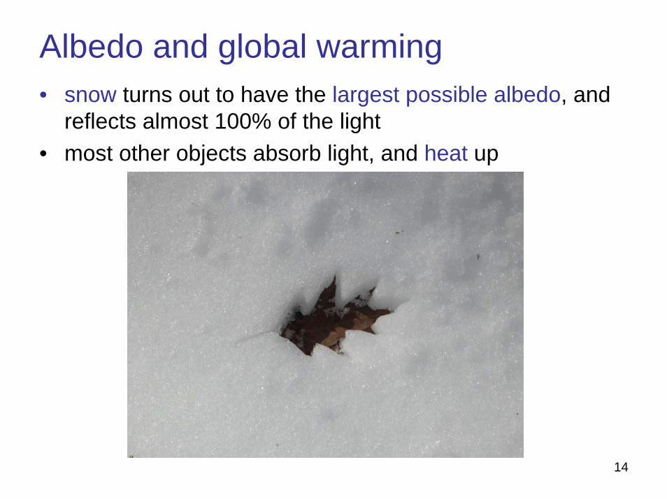
Albedo and global warming• snow turns out to have the largest possible albedo, and
reflects almost 100% of the light• most other objects absorb light, and heat up
14

Albedo and global warming• by reflecting most of the
incident light• the polar cap cools off
the planet• as ice melts, less light
is reflected• the planet warms up,
more ice melts, etc.• this is one of the main
reasons for globalwarming
1 Light colored ice reflects back the Sun’s energy efficiently.
2 Exposed land is darker colored and absorbs more energy.
3 As the ice melts, more land is exposed. This absorbs more heat, melting more ice.
4 The altitude of the melting ice is reduced so itbecomes harder for new ice to form.
15

Albedo and parking lots• these day, this effect is taken very seriously• it turns out that increasing reflections is useful in many
other ways• for example, it can save a lot of lighting (energy)• an example of how paving parking lots with pavement
of higher reflectance can make a difference
16

Angles• is the object albedo the only factor that matters for how
much light it reflects?• no, the angle at which the light is incident also matters
α1
α2
incident light
reflected light
image brightness
Po
Pi
V
17

Light
18
• this is easy to see• consider the following experiment
• energy absorbed by object depends on its surface area• this varies with the incident angle• concept that captures this dependence on angles is that
of foreshortening
sheet of paper
lots of reflected light no reflection

Light• foreshortening: very important concept
– tilted surface looks smaller than when seen at 90o
– best understood by example– if I show you a tilted person it looks smaller than when you view
you at 90o
foreshortening
19

Light
20
• what is the foreshortened area for a patch of area dA?
• it depends on the angle θ between– the normal to the patch– viewing direction
• for a known area dA we can actually compute the foreshortening factor
dA
θ
viewing direction
patch normal
Light
21
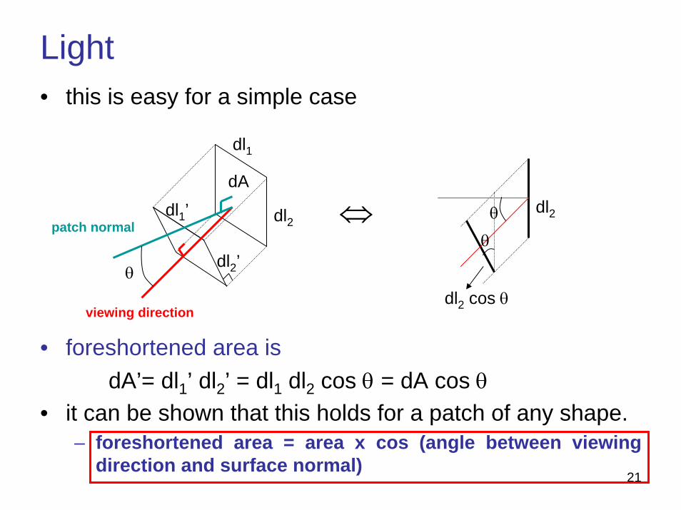
• this is easy for a simple case
• foreshortened area isdA’= dl1’ dl2’ = dl1 dl2 cos θ = dA cos θ
• it can be shown that this holds for a patch of any shape.– foreshortened area = area x cos (angle between viewing
direction and surface normal)
dl1
dl2
dA
θ
dl1’
dl2’
θ
θ
dl2
dl2 cos θ
⇔
viewing direction
patch normal

Lambertian surfaces
22
• putting everything together, – we have an equation for the light reflected by
an object– assuming surface reflects equally in
all directions (Lambertian)– outgoing radiance is
– “light reflected at point P in direction Vo = albedo at P x incidentlight from direction Vi x cos (normal, incident)”
– note that • it holds for any outgoing direction Vo
• is a function of Vi
• if there are multiple incoming directions, we have to integrate over Vi
φo
oiiO VVPLPVPL ∀= ,cos),()(),( θρ
θo
θi
Vi Vo
P

Lambertian surfaces• this allows us to propagate light throughout a scene
θ1
Po
Vo
θ2
P1
V1
V2
2211121 , cos)(),(),( VPVPLVPL ∀= θρ
23

Lambertian surfaces• using constancy of radiance along
straight linesθ1
Po
Vo
θ2
P1
V1
V2
2211121 , cos)(),(),( VPVPLVPL ∀= θρ
),(),( 1011 VPLVPL =
2211021 ,, cos)(),(),( VPVPLVPL ∀= θρ
c
24

Lambertian surfaces• using reflection equation again
θ1
Po
Vo
θ2
P1
V1
V2
c
1100010 ,cos)(),(),( VPVPLVPL ∀= θρ
1
2010021
cos x x cos)()(),(),(
θθρρ PPVPLVPL =
2211021 , cos)(),(),( VPVPLVPL ∀= θρ
25

Lambertian surfaces• and we have a rule for any
number of bounces
VPVPLVPLn
ii
n
iin ∀⎥
⎦
⎤⎢⎣
⎡⎥⎦
⎤⎢⎣
⎡= ∏∏
+
==
,cos)(),(),(1
1000 θρ
θ1
Po
Vo
θ2
P1
V1
V2
26

Lambertian surfaces• note that on
– unless all cosines are close to 1– their product goes to zero quickly– e.g. see decay of cosn(θ) with n– this means that only light that
arrives frontally to all the bounces gets propagated very far
– such an alignment is very unlikely– we don’t really have to worry
about many bounces– the process becomes tractable
VPVPLVPLn
ii
n
iin ∀⎥
⎦
⎤⎢⎣
⎡⎥⎦
⎤⎢⎣
⎡= ∏∏
+
==
,cos)(),(),(1
1000 θρ
27

Lambertian surfaces• on the other hand,
– there are still various single-bounce paths– e.g. each source has a single bounce path to each non-shaded
object– to deal with this we need to know more about light sources
θ1
Po
Vo
θ2
P1
V1
V2
V’1
28
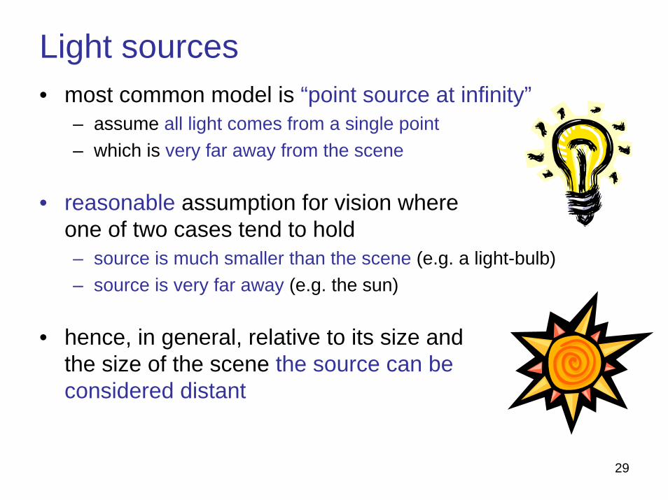
Light sources• most common model is “point source at infinity”
– assume all light comes from a single point– which is very far away from the scene
• reasonable assumption for vision whereone of two cases tend to hold– source is much smaller than the scene (e.g. a light-bulb)– source is very far away (e.g. the sun)
• hence, in general, relative to its size and the size of the scene the source can be considered distant
29
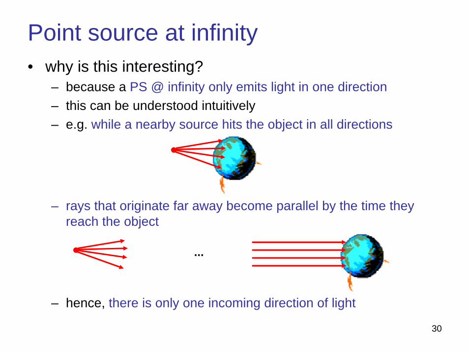
Point source at infinity• why is this interesting?
– because a PS @ infinity only emits light in one direction– this can be understood intuitively– e.g. while a nearby source hits the object in all directions
– rays that originate far away become parallel by the time they reach the object
– hence, there is only one incoming direction of light
...
30

Lambertian surfaces• in summary, we have
– PS @ infinity– Lambertian surface
• we know that– only paths with a few bounces, from source to object, matter– source light hits each object along single direction
• we can go back to our original scenario
α1
α2
incident light
reflected light
image brightness31

Lambertian surfaces
32
• overall, we have an extremely simple relationship!
• the power at pixel Pi is the product of– source power E, – albedo of the object at reflection point, – and angle between source direction and object normal
θρ cos)()( 0PEPP i =
θ
image brightness
Po
Pi
V
θ
Lightdirection
E

Lambertian surfaces• note that
– if n is the surface normal and s the light direction– the two vectors have unit norm– then cos θ = n . s and
sPnPEPP irr ).()()( 00ρ=
33
θ
θ2
image brightness
Po
Pi
V
E θ
Lightdirection
nr
sr
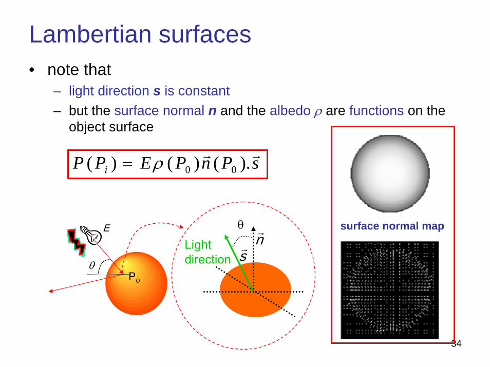
Lambertian surfaces
34
• note that – light direction s is constant– but the surface normal n and the albedo ρ are functions on the
object surface
θPo
E θ
Lightdirection
nr
sr
surface normal map
sPnPEPP irr ).()()( 00ρ=

Vision vs graphics• this is a nice example of why vision is much harder than
graphics
– graphics: given ρ, n, and s compute P – this is just a multiplication– vision: given P, find ρ, n, and s– really hard problem– note that both ρ and n depend on the
pixel, so the # of unknowns is three times the # of constraints
– cannot be solved, unless we make assumptions about these functions
surface normal map
sPnPEPP irr ).()()( 00ρ=
35
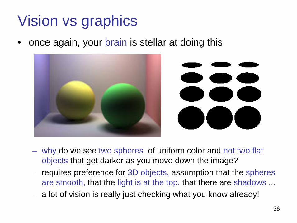
Vision vs graphics• once again, your brain is stellar at doing this
– why do we see two spheres of uniform color and not two flat objects that get darker as you move down the image?
– requires preference for 3D objects, assumption that the spheres are smooth, that the light is at the top, that there are shadows ...
– a lot of vision is really just checking what you know already!36

Vision• it turns out that if you make the right assumptions
– it can be done– research problem, not perfect yet
image shading (cos θ) albedo (ρ)
37

Multiple light sources• finally, note that the equation is linear on s
• if we have n PS @ infinity, we can just assume that s = s1 + ...+ sn
• resulting image is sum of the images due to each source
sPnPEPP irr ).()()( 00ρ=
∑∑
∑==
=
ik
kk
kk
PsPnPE
sPnPEP
).()(
).()(
00
00
rr
rr
ρ
ρ
38

39