review: hot stage engineering to improve slag · review: hot stage engineering to improve slag...
TRANSCRIPT


2nd International Slag Valorisation Symposium | Leuven | 18-20/04/2011 231
Review: Hot stage engineering to improve slag valorisation options
Fredrik ENGSTRÖM1, Yiannis PONTIKES2, Daneel GEYSEN2, Peter Tom JONES2, Bo BJÖRKMAN1, Bart BLANPAIN2 1 Department of Chemical Engineering and Geosciences, Luleå University of Technology, 971
87 Luleå, Sweden 2 Centre for High Temperature Process and Sustainable Materials Management, Department
of Metallurgy and Materials Engineering, Katholieke University of Leuven, Kasteelpark
Arenberg 44 bus 2450, B-3001 Heverlee (Leuven), Belgium
[email protected], [email protected],
[email protected], [email protected],
[email protected], [email protected]
Abstract
A number of studies are briefly reviewed dealing with hot stage processing of slags,
i.e. additions during the molten state and variations of the cooling path, and the
influence on the microstructure and properties of solidified slags. Emphasis is placed
on research and developments in the last five years, although other works that
created the thinking framework for several of the current practices are also
mentioned. The additions include: a) quartz sand with concurrent oxygen injection for
the minimisation of free CaO and MgO, b) various materials for the modification of
the composition of liquid blast furnace slag after tapping, c) borates and boron
wastes and their distribution in both synthetic and industrial stainless steel slags, d)
phosphates in stainless steel slags and their distribution in BOF slags e) waste glass
and fly ash for the stabilisation of stainless steel slags, f) K2CO3 for the production of
potassium silicate fertiliser from steelmaking slag and g) bauxite, Al2O3 containing
residues and aluminium metal that enhance the Cr recovery and minimise leaching in
EAF slags. In terms of cooling, the effect of cooling rate on the final mineralogy, as a
way to stabilise stainless steel slags and to control free lime formation in BOF slags, is
presented. A more in-depth discussion regarding leaching performance, which has
been identified as a key issue in slag valorisation, is also taking place. Although it is
acknowledged that many research questions are still open and that both technical
and economical barriers exist, it is strongly believed that a conscious hot stage
processing step can both increase slag utilisation rates and make higher value
applications achievable.

2nd International Slag Valorisation Symposium | Leuven | 18-20/04/2011 232
Introduction
The iron and steelmaking industry is a major producer of slag, contributing by about
390 million tonnes in 2009.1 About two thirds of this slag originates from blast
furnace processes, while the remaining third comes from steelmaking operations.
Considerably less slag is formed during speciality steel and ferrous alloy production.
However, the amount of stainless steel slag, for example, still added up to 8.2 million
tonnes in 2009.2,3 In the same year, the copper industry was responsible for
approximately 35 million tonnes of slag,4,5 making it the main non-ferrous slag
producer.
In (stainless) steel production, conventionally, the molten slag is disposed with
minimal considerations regarding energy recuperation or quality of the cold product.
However, this is not the case for blast furnace slags, where granulation has enabled
the delivery of a higher added value product that finds application as supplementary
cementitious material. It is therefore suggested that there is a considerable potential
to influence the functional properties of the cold slag without making compromises
towards metal or process quality. This can be done by hot-stage engineering that
reflects changes occurring in a liquid state in order to steer the properties of the
cold, solidified product, to a desirable direction.
In more detail, hot-stage engineering can involve: a) additions during the molten
state of the slag for reduction and separation of a metallic phase or stabilisation of
minerals (and complementary additions to secure the dissolution of the materials
added); this can be done before, during or after tapping and b) selection of
appropriate cooling paths to deliver the desirable product. Energy recuperation
during cooling is also a topic of great interest. The drive behind hot-stage engineering
is the need for slag products that comply with environmental legislation and possibly,
receive higher value in the market. In the majority of the plants nowadays, after the
hot (stainless) steel slag is separated from the metal, it is typically cooled slowly to
ambient temperatures in the slag yards. Minimal additions take place and
granulation is not widely practised although there are indications it is receiving more
consideration,6 possibly also combined with energy recuperation (see also
contribution by Guangqiang Li and Hongwei Li in this Symposium Book).7,8
This work aims to present laboratory experiments and industrial trials/practices,
relevant to hot stage processing that induce better slag properties. As leaching
performance has been identified as a key issue in slag valorisation, a more in-depth
discussion is presented. This work is building upon a review paper recently published
by Durinck et al.9 and aims to establish a tradition linked with the Slag Valorisation
Symposia.

2nd International Slag Valorisation Symposium | Leuven | 18-20/04/2011 233
Additions during the molten state of slag
Effect on stability due to free CaO or MgO
The presence of free CaO or MgO in the slag leads to a longer term volume instability
due to the expansive hydration to Ca(OH)2 and Mg(OH)2. However, a process has
been devised and implemented to address this.10-12 The principle of this process lies
in the introduction of additives in order for free CaO and MgO to react towards a
stable matrix of calcium silicates and ferrites. This can be achieved by the addition of
SiO2-containing materials, such as quartz sand, glass cullet and spent foundry sands.
The treatment with quartz sand offers the advantage of higher SiO2 content per mass
of additives and is not introducing other components that can cause side reactions.
In Figure 1 a schematic drawing of the process is presented (sse also contribution by
Mudersbach et al. in this Symposium Book). The quartz sand is injected
pneumatically into the slag pot. The sand is transported by N2. The necessary oxygen
is added in the cone of the dispenser. Oxygen is required for the treatment process
in order to supply additional heat by means of FeO oxidation, dissolve the added
sand, and keep the slag liquid. The process is currently operational at ThyssenKrupp
Duisburg and ArcelorMittal Gent.
Chemistry of blast furnace slag
It is known that granulated blast furnace slag has latent hydraulic properties and is
used as supplementary cementitious material and as addition in concrete.
Experiences in recent past however indicate a drop-down of both, slag basicity
(CaO/SiO2) and Al2O3-content, in blast furnace slag.13 This change has as a result
lower compressive strength of mortar or concrete and an influence on the early
stage of strength development. A thorough presentation on the way FEhS-Institute
Figure 1: Kühn et al.11 developed a process for dissolving a large quantity of SiO2 (~10
wt%) in carbon steelmaking slags. By co-injecting oxygen, the slag is stirred and FeO
in the slag is oxidised to Fe2O3, generating the required heat to dissolve the SiO2.
Adapted from Ref.13

2nd International Slag Valorisation Symposium | Leuven | 18-20/04/2011 234
attempted to tackle this challenge was given by P. Drissen and D. Mudersbach;13 a
summary is presented herein.
As described, the envisaged solution involved modification of the composition of the
liquid blast furnace slag after tapping, prior to granulation.14 Tests were done with
lime, calcium carbide, synthetic fluxes of lime and aluminium oxide, BOF-slag and
slag from secondary metallurgy. During operational trials the injection of modifiers
has been tested in the main runner (slag and hot metal), in the skimmer and in the
slag runner (slag only). A schematic drawing of the process is shown in Figure 2.
Addition into the slag runner was not successful because the heat capacity of the slag
limited the amount of modifiers. Experiments with exothermic modifiers, like calcium
carbide, were stopped for safety reasons. Trials on the pneumatic injection in the
skimmer had to be stopped because too much hot metal was spilled over to the slag
runner and might have caused trouble in granulation. The addition of lime by
pneumatic injection into the main runner was successfully tested. The lime was
totally dissolved in the slag and the slag ratio was increased from 1.1 to 1.4. This
increase was the reason for roughly 25% gain in compressive strength of mortar
prisms. Unfortunately the injection process had to be operated batch wise.
Continuous operation throughout the entire tapping time was not possible due to
the limited capacity of the available bunker system and the required injection rates
of up to 100 kg lime per minute.
Effect on stability due to beta to gamma transformation of dicalcium silicate
The option of inhibiting the β to γ transformation of C2S was first elaborated in 1986
by Seki and co-workers,15 who developed a borate based stabiliser for stainless steel
decarburisation slag. Typical boron minerals are kernite (Na2B4O6(OH)2.3H2O),
Figure 2: Modification of blast furnace slag composition, schematic drawing. Adapted
from Ref.13

2nd International Slag Valorisation Symposium | Leuven | 18-20/04/2011 235
colemanite (CaB3O4(OH)3.H2O) and borax (Na2B4O5(OH)4.8H2O) whereas lately,
boron-containing glazing powders16 with promising results were also used.
In terms of boron distribution in the slag, D. Durinck et al.17 performed experiments
on a 52% CaO – 39% SiO2 – 9% MgO synthetic stainless steel slag. Sodium tetraborate
decahydrate (Na2B4O7.10 H2O) was added to the slag, and after heating at 1640°C,
slow cooling and quenching experiments were performed. The overall borate level in
the synthetic slags of this study varies from 0 to 1.83 wt% B2O3. Six phases were
identified and analysed using EPMA-WDS for their borate content: C2S (C = CaO, S =
SiO2), bredigite (C7MS4, M = MgO), merwinite (C3MS2), akermanite (C2MS2), pseudo-
wollastonite and a CxSyBz phase. Results show that B2O3 is found in solid solution with
C2S. This is the boron which is responsible for the stabilisation of β-C2S. The
substitution occurs as (Ca)2-0,5x(SiO4)1-x(BO3)x.18 Dissolved B2O3 is also found in the
other phases, such as bredigite and pseudo-wollastonite. The highest concentration,
however, is found in a CxSyBz phase. This phase is a ternary compound between CaO,
SiO2 and B2O3 with composition: 18-23 at% Ca, 3-4 at% Si, 15-19 at% B and 55-60 at%
O. The authors conclude that the only way to significantly increase the borate level in
C2S is to add more borates. Changing the slag composition has little effect. Moreover,
it is suggested that slag stabilisation with borates not only depends on the chemical
stabilisation but also on the cooling rate and the matrix constraint. The latter is
believed to be influenced by the amount of C2S in the slag and, therefore, the slag
composition. A low basicity slag contains a low amount of C2S grains, which are
better constrained by the surrounding phases.
In industry however, the borates are added to a molten slag and the time scale is
much shorter than laboratory scale experiments like above, where the
thermodynamic equilibrium was of interest. Consequently, diffusion of the B2O3 into
the existing C2S is required for the formation of a solid solution. Results reported
elsewhere19 indicate that the borate level in the C2S phase of a quenched slag is
similar to that in the C2S phase of the slowly cooled industrial samples. This
corroborates that at high temperatures the diffusion of boron in the C2S phase
present in the slag does indeed occur.19
To validate the experimental borate distribution for a typical industrial practice, the
borate distribution in treated industrial stainless steel AOD slag was also determined
for two distinct melt shops. In both cases Na2B4O7 was added to the slag by injection
in the slag stream during slag/steel separation. The results were recently reported
elsewhere.20
In Meltshop 119,20 one boron stabilised slag sample was studied in detail. The
addition amounted to about 1.5 wt% of the slag weight as B2O3. The phase

2nd International Slag Valorisation Symposium | Leuven | 18-20/04/2011 236
constitution of the industrial slag includes C2S, bredigite and merwinite. The boron
rich phase CxSyBz was once more detected. As fluorine is added to the slag to increase
its fluidity, cuspidine (C4S2O7F2) formed in the later stages of solidification instead of
akermanite and pseudo-wollastonite. Furthermore, the inevitable presence of
chromium oxide in the industrial slag leads to (Mg)[Cr,Al]2O4 spinel formation.
Despite these small differences in phase constitution, the (qualitative) boron
distribution is not significantly different from that in the synthetic slags. C2S and
bredigite show small but clear boron peaks in WDS spectra. The net peak heights are
just below those of the same phases in the synthetic sample. Merwinite contains a
boron level close to the detection limit. Cuspidine holds some boron as well.
In Meltshop 220 five industrial samples (A-E) were studied to quantitatively analyse
the boron distribution over the different phases. Boron was measured in each
separate mineralogical phase of the different AOD slag yard samples with EPMA-
WDS, Table 1, using a Cameca SX52 microprobe.
Table 1: Overview of B2O3 concentration (in wt%) in the different phases of industrial
AOD slag stabilised with boron (5 samples : A, B, C, D, E named)20
Phase B2O3, wt%
A
B2O3, wt%
B
B2O3, wt%
C
B2O3, wt%
D
B2O3, wt%
E
Free MgO 0.57 0.43 0.37-0.73 0.37 0.57
C2S - 0-0.16 0.53-0.60 - -
Bredigite 0.25-0.39 0.21 - - 0-0.13
Merwinite 0 – 0.23 - - - -
Cuspidine 1.40 – 1.66 - - 0.1 0.72
Metal 0.68 0.49-0.52 0.52-0.84 0.52 0.67
CaF2 - 0.55 0.48-0.90 - -
Q-XRD based on Rietveld analysis was used to determine the amount of the different
phases in the sample, Table 2. Metal particles (clearly determined with BSI) and the
CXSyBz phase were not detected by XRD. The overall ‘B2O3’ level in the oxidic slag
phases (excluding both the metal particles and the CXSyBz) were determined by
combining EPMA-WDS and Q-XRD data. The total B level in the slag was also
determined by wet chemical analysis. Finally, results are compared to process data
from 52 heats.
The same authors20 also performed elemental mapping to determine the B
distribution, by using a FEG-EPMA JXA-8530F of JEOL. Figure 3 shows the elemental
mapping of boron (top right), silicon (bottom left) and iron (bottom right) for two
industrial samples. In general, the matrix is poor in B. Distinct phases with high boron
2nd International Slag Valorisation Symposium | Leuven | 18-20/04/2011 237
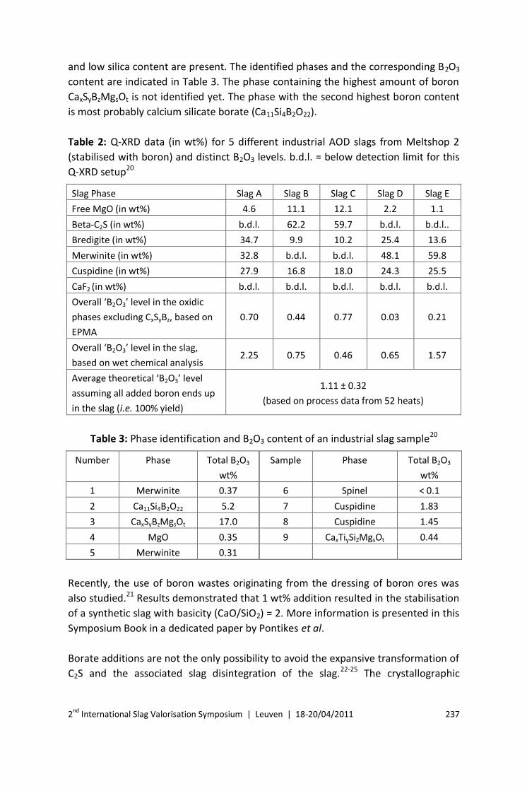
and low silica content are present. The identified phases and the corresponding B2O3
content are indicated in Table 3. The phase containing the highest amount of boron
CaxSyBzMgsOt is not identified yet. The phase with the second highest boron content
is most probably calcium silicate borate (Ca11Si4B2O22).
Table 2: Q-XRD data (in wt%) for 5 different industrial AOD slags from Meltshop 2
(stabilised with boron) and distinct B2O3 levels. b.d.l. = below detection limit for this
Q-XRD setup20
Slag Phase Slag A Slag B Slag C Slag D Slag E
Free MgO (in wt%) 4.6 11.1 12.1 2.2 1.1
Beta-C2S (in wt%) b.d.l. 62.2 59.7 b.d.l. b.d.l..
Bredigite (in wt%) 34.7 9.9 10.2 25.4 13.6
Merwinite (in wt%) 32.8 b.d.l. b.d.l. 48.1 59.8
Cuspidine (in wt%) 27.9 16.8 18.0 24.3 25.5
CaF2 (in wt%) b.d.l. b.d.l. b.d.l. b.d.l. b.d.l.
Overall ‘B2O3’ level in the oxidic
phases excluding CxSyBz, based on
EPMA
0.70 0.44 0.77 0.03 0.21
Overall ‘B2O3’ level in the slag,
based on wet chemical analysis 2.25 0.75 0.46 0.65 1.57
Average theoretical ‘B2O3’ level
assuming all added boron ends up
in the slag (i.e. 100% yield)
1.11 ± 0.32
(based on process data from 52 heats)
Table 3: Phase identification and B2O3 content of an industrial slag sample20
Number Phase Total B2O3
wt%
Sample Phase Total B2O3
wt%
1 Merwinite 0.37 6 Spinel < 0.1
2 Ca11Si4B2O22 5.2 7 Cuspidine 1.83
3 CaxSyBzMgsOt 17.0 8 Cuspidine 1.45
4 MgO 0.35 9 CaxTiySiZMgsOt 0.44
5 Merwinite 0.31
Recently, the use of boron wastes originating from the dressing of boron ores was
also studied.21 Results demonstrated that 1 wt% addition resulted in the stabilisation
of a synthetic slag with basicity (CaO/SiO2) = 2. More information is presented in this
Symposium Book in a dedicated paper by Pontikes et al.
Borate additions are not the only possibility to avoid the expansive transformation of
C2S and the associated slag disintegration of the slag.22-25 The crystallographic

2nd International Slag Valorisation Symposium | Leuven | 18-20/04/2011 238
coordination number, the ionic radius and the ionic valence of the doping ion all
affect the deformation of the C2S crystal and, as a consequence, the stabilisation.
Recently, a qualitative criterion based on ionic radius, ionic valence and
crystallographic structure of the additive was developed,26 which is capable of
predicting whether or not a compound will stabilise the β-polymorph. In practice,
different oxides have been reported to stabilise the different polymorphs of
dicalcium silicate. The α and α΄ polymorphs have been reported to be stabilised by
oxides such as MgO, A12Ο3, Fe2O3, BaO, K2O, P2O5 and Cr2Ο3. The β polymorph can be
stabilised by the addition of Na2Ο, K2Ο, BaO, MnΟ2, Cr2Ο3 or their combinations.22
The difference in the stabilising ability of each oxide provides a certain degree of
flexibility if the goal is to avoid the formation of the γ phase.
Based on this knowledge, the effect of phosphate additions to disintegrating stainless
steelmaking slags was investigated. Satisfactory stabilisation was obtained,27 but
compared to borate additions a significantly larger amount of phosphates (~ 2 wt%)
was required to avoid disintegration. Working on a similar direction, Yang et al.28
studied the effect of a feed grade mono-calcium phosphate (with 47.2 wt% P2O5) and
a by-product from iron ore processing (with 9.0 wt% P2O5). The formation of γ-C2S
(and slag disintegration) was prevented for a P addition in the slag higher than 0.3
wt%; only β- and α΄-C2S were detected.
Even if the mechanism of P stabilisation has not been studied – to the best of our
knowledge – on stainless steel slags, some light is shed by a recent work on BOF
slags. In this work,29 the authors study the P speciation in BOF slags, rich in dicalcium
silicates and with a phosphorus content that could jeopardise internal recycling
Figure 3: Elemental mapping for B, Si and Fe of an industrial slag sample, performed
with a FEG-EPMA. Adapted from Ref. 20
2nd International Slag Valorisation Symposium | Leuven | 18-20/04/2011 239
within the steel mill. One industrial sample and two prepared in laboratory
conditions (described and studied elsewhere30), at different cooling rates, were
studied. As indicated, BOF slag recycling in France is limited both in road
construction, due to its free lime content, and internally in the steel mill, due to its
phosphorus content. Consequently, there is a clear merit in more fundamental
studies in order to understand/control both P speciation and free lime formation.
The results indicate that the main phases in the BOF slag are dicalcium silicate
(theoretical composition Ca2SiO4), calcium alumino-ferrite (theoretical composition
Ca2FeAlO5), free lime (CaO) and wustite (FeO), with Fe substituted by Mg and Mn, as
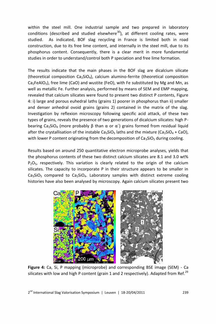
well as metallic Fe. Further analysis, performed by means of SEM and EMP mapping,
revealed that calcium silicates were found to present two distinct P contents, Figure
4: i) large and porous euhedral laths (grains 1) poorer in phosphorus than ii) smaller
and denser anhedral ovoid grains (grains 2) contained in the matrix of the slag.
Investigation by reflexion microscopy following specific acid attack, of these two
types of grains, reveals the presence of two generations of dicalcium silicates: high P-
bearing Ca2SiO4 (more probably β than α or α΄) grains formed from residual liquid
after the crystallisation of the instable Ca3SiO5 laths and the mixture (Ca2SiO4 + CaO),
with lower P content originating from the decomposition of Ca3SiO5 during cooling.
Results based on around 250 quantitative electron microprobe analyses, yields that
the phosphorus contents of these two distinct calcium silicates are 8.1 and 3.0 wt%
P2O5, respectively. This variation is clearly related to the origin of the calcium
silicates. The capacity to incorporate P in their structure appears to be smaller in
Ca3SiO5 compared to Ca2SiO4. Laboratory samples with distinct extreme cooling
histories have also been analysed by microscopy. Again calcium silicates present two
Figure 4: Ca, Si, P mapping (microprobe) and corresponding BSE image (SEM) - Ca
silicates with low and high P content (grain 1 and 2 respectively). Adapted from Ref.29
2nd International Slag Valorisation Symposium | Leuven | 18-20/04/2011 240
distinct P contents. Decomposed Ca3SiO5 predominates over Ca2SiO4 in industrial
cooling. On the contrary, slow cooling – closer to equilibrium conditions – favours
primary Ca2SiO4 formation that incorporates larger amounts of P in its structure.
Phosphorus content is thus ‘diluted’ in a higher proportion of grains, which explains
the decreasing values from 8% to 5.3% with slower cooling, Table 4.
Table 4: P content in calcium silicates in BOF slag; various cooling conditions29
% P2O5 Rapid cooling
‘Industrial’
cooling
(quantity)
Slow cooling
(quantity)
Ca2SiO4 (P+) 4.5
8.0 (+) 5.3 (++)
Decomposed Ca3SiO5 (P-) 2.9 (++) 2.4 (+)
Alternatively, slag disintegration can be averted by modifying the slag composition in
order to avoid the presence of C2S. Already in 1942, compositional limits were
defined for disintegrating slags,31 based on the stability field of C2S in the CaO-MgO-
SiO2-Al2O3 system, with an adjustment for the sulphur content (S) in the slag.
However, in many cases, slags that meet these conditions do not have the
appropriate high temperature metallurgical functionality. In stainless steelmaking,
C2S free, low basicity slags cause rapid refractory degradation and low chromium
yields.32 To avoid making such compromises towards process and metal quality, the
slag composition must be adjusted after slag/metal separation. Adding a relatively
large amount of silica seems to be the best way to avoid C2S. This was proven on a
laboratory scale by Sakamoto,33 who stabilised a stainless steel decarburisation slag
with 12 wt% of waste glass, containing 70-75 wt% SiO2. The same authors also
demonstrated the potential of this method in trials with waste glass in the slag pot. A
similar approach by adding quartz sand was investigated by Yang et al.28 In this case,
the formation of γ-C2S (and slag disintegration) was prevented for a sand addition of
5.12 wt%, resulting to a basicity CaO/SiO2 = 1.34. Depending on the amount required
for stabilisation, an additional slag treatment process is potentially required for an
effective dissolution. The principle of this step can be similar to the method
developed by Kühn et al. 10,11, Figure 1.
An alternative option, as described by Kitamura et al.34, is to mix stainless steel slag
with cold or preheated non-ferrous fayalite slag. In this way, the basicity of the slag
can be substantially reduced, avoiding the formation of C2S. The FeO from the non-
ferrous slag is used as an additional energy source (exothermic reaction to Fe2O3
results in additional heat to dissolve the SiO2). However, this method has only been
shown to work on a lab-scale level. Heat balance calculations34 have shown that a
mixing ratio of maximum 15% (non-ferrous slag to stainless steel slag) can be

2nd International Slag Valorisation Symposium | Leuven | 18-20/04/2011 241
achieved. However, this would be insufficient to reduce the C/S ratio to a low enough
level. The scale up of this process to the industrial level is probably going to
necessitate additional measures.
In a similar direction, fly ash originating from lignite’s combustion was investigated
for the stabilisation of a synthetic slag with basicity (CaO/SiO2) = 2. Results indicate
that 22 wt% is sufficient. More information is presented in this conference in a
dedicated paper by Pontikes et al.
In Japan, a new steelmaking process developed by NKK and referred as ZSP (Zero Slag
Process)35,36 claims to lower the amount of generated slag and also stabilises the
composition of slag generated through hot metal pre-treatment. The production of a
potassium silicate fertiliser is an interesting example. The newly developed fertiliser
is difficult to dissolve in water, and slowly dissolves in the weak citric acid released by
plant roots. The process is presented in Figure 5. At the desiliconisation station in the
hot metal pre-treatment process, hot metal is first subjected to desiliconisation
treatment and then, potassium carbonate (K2CO3) is continuously added into the hot
metal ladle from the hopper above the ladle while agitating the hot metal using
nitrogen gas. Uniformly melted slag is recovered from the hot metal ladle, solidified
by cooling, and crushed into a granular form.
The effectiveness as a fertiliser was investigated by the “Japan Fertiliser and Feed
Inspection Association”. NKK’s fertiliser demonstrated an effectiveness equal to
other commercial potassium silicate fertilisers and combined potassium chloride-
calcium silicate fertilisers.37 In January 2000, as a result of these tests verifying the
effectiveness of a potassium silicate fertiliser made from steelmaking slag, the
Figure 5: Production of potassium silicate fertiliser from steelmaking slag. Adapted
from Ref.36

2nd International Slag Valorisation Symposium | Leuven | 18-20/04/2011 242
Ministry of Agriculture, Forestry and Fisheries of Japan issued a new official fertiliser
standard “Fused potassium silicate fertiliser” in its Notice No. 91 based on the
Fertiliser Control Law. NKK registered its fertiliser as “Mn-containing 20.0 fused
potassium silicate fertiliser” with the Ministry in April 2000 and started marketing it
in December 2001.
In another work, Mudersbach et al.38 suggest the additions of bauxite, Al2O3
containing residues and aluminium metal as a method to increase the stability of
stainless steel EAF slags and to stabilise chrome. The aim of the additions is to
decrease the basicity of the slags and favour the formation of spinel type phases
during solidification. In that event, even if the slag contains high chrome contents,
the leaching of chrome can be suppressed. Mudersbach et al.38 also developed the
so-called “factor sp” to empirically describe the expected chromium content based
on the slag composition:
factor sp = a * MgO + b * Al2O3 + c * FeOn – x * Cr2O3 [wt.%] (1)
Their work shows that there is a correlation between the spinel factor and the
actually measured chromium leaching levels (which seem to confirm that spinel
behaves, in practice, as a stable phase with respect to chromium leaching). More
specifically, the authors propose three types of additions which should mitigate any
chromium leaching problems from EAF slags:
Additions of bauxite (600 kg/transfer ladle), increasing the “factor sp” to 15
wt.%;
Additions of Al2O3 containing residues (so-called TE 75, a product containing
75-85 wt.% Al2O3);
Additions of aluminium metal which not only improve the chromium recovery
but also enhance the “factor sp”.
In a work also related to Al additions, G. Stubbe et al.39 recently reported in a
detailed paper their results on aluminium injection to EAF slags. This work has been a
co-operation between VDEh-Betriebsforschungsinstitut (BFI) and BGH Edelstahl
Siegen (BGH), Germany. After the successful operational trials, Al injection is
industrially applied at the BGH stainless steel plant.
The operational trials have been performed at BGH Edelstahl Siegen GmbH in a 40
tonne EBT-EAF furnace. The furnace is equipped with several side wall
injectors/burners used for solid material injection (e.g. lime and carbon). Preceding
the date of the trials, the normal operational included the addition of ferrosilicon
(FeSi) for chromium recovery from the slag. For the operational Al injection trials, an

2nd International Slag Valorisation Symposium | Leuven | 18-20/04/2011 243
injection device, composed of a rotor injection machine and two dosing units for big-
bag charging, was employed. The Al source was mechanically processed Al granules
with a maximum grain size of 2 mm. The aluminium was injected via one side wall
injector/burner located near the furnace door. The target amount of the injected
aluminium was 15 kg Al per tonne of liquid steel. In order to be able to inject the
whole amount of aluminium within 10 minutes during the flat bath period at the end
of the melting time, the injection rate of the aluminium was adjusted to
approximately 60 kg/min.
By injection of the aluminium granules into the EAF slag, the average chromium
oxide mass fraction in the final slag was 3.4% for ferritic steels and 1.6% for
austenitic steels. In comparison to normal operation, the chromium recovery yield
was 67% for ferritic steels and 87% for austenitic steels. Electric energy savings were
9% for ferritic and 6% for austenitic steels. This is attributed to the additional
chemical energy input. In both cases, the energy output via slag and cooling water
increases significantly.
The authors conclude by reporting that BGH Edelstahl Siegen has implemented the
aluminium injection into the EAF as new standard operational practice for stainless
steel production since mid 2009. For aluminium injection, a new solid material
injector has been installed, which is able to inject aluminium or lime alternatively
into the EAF slag at an injection rate of maximum 100 kg/min. For a more efficient
penetration of the aluminium (or lime alternatively) into the slag, the material is
conveyed to the melt supported by a concentric coherent oxygen jet. Due to this
supported injection directly into the slag, the solid material losses to the exhaust
system are minimal and subsequently an improved material yield is achieved.
The most important benefits of Al injection are summarised as follows: a) high Cr
recovery in the steel and low total Cr level in the slag, opening the potential for
higher added-value applications, b) electric energy consumption was decreased by
10% approximately and power-on-time by 17%, c) Cr bound most probably in spinel
phases, lower leaching expected, d) final slag chemistry close to calcium aluminate
cements, potential for production of such hydraulic binders in the plant, high price of
calcium aluminate cements in the market. On the other hand, Al is also expensive,
with a fluctuating price in the market, and the availability of such streams cannot be
taken for granted. Mixed Al sources or lower purity streams could be also seen as
options.
2nd International Slag Valorisation Symposium | Leuven | 18-20/04/2011 244
Variations in cooling rate
Effect on the stabilisation of tricalcium and dicalcium silicate
Fast cooling in order to prevent the transformation of tricalcium silicate to calcium
oxide and dicalcium silicate, as well as, that of β-dicalcium silicate to γ-dicalcium
silicate, is standard practice for the cement industry. Dedicated studies have also
proved the interconnection between cooling rate, final mineralogy and hydraulic
properties.40 This stabilisation method was further developed by showing on a
laboratory scale that a granulation process transforms a disintegrating slag into a slag
product suitable for construction applications.41 Similar results have been reported
also elsewhere,28 where it was demonstrated that air granulation was effective in
preventing the formation of γ-C2S in a slag with basicity CaO/SiO2 = 1.6.
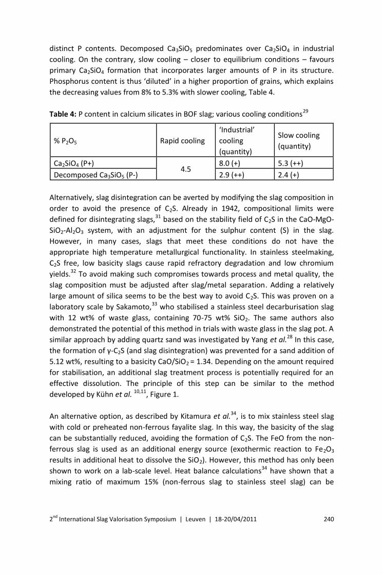
Recent results demonstrate that fast cooling, by means of dry granulation, is
effective in suppressing the β to γ transformation of C2S, for basicity CaO/SiO2 as high
as 2.2. An extensive network of dendritic merwinite is formed on a stabilised β-C2S,
Figure 6. This work is in progress and results will be presented in the near future.42
The effect of cooling rate was also studied on BOF slags.30 A sample with a
representative composition of BOF slag was subjected to heating at 1600°C for 5 h,
followed by rapid cooling by means of water quenching and slow cooling of 72 h
approximately. The cooled sample was compared to a sample from the industrial
site, cooled within 24-48 h, which represents an intermediate state. The results
demonstrate that cooling conditions strongly affect the microstructure, both
qualitatively and quantitatively, Figure 7. Compared to the industrial sample, slow
cooling results to very low CaO and Ca3SiO5, higher Ca2SiO4 and MgO, and formation
of Ca2Fe2O5 instead of FeO. On the other hand, the water quenched slag is composed
of mainly Ca3SiO5 and Ca2SiO4, Ca2Fe2O5, MgO and a small amount of CaO. In
addition, the growth of the crystals is different in each cooling process, the silicates
Figure 6: SEM images on chemically etched synthetic slag samples of basicity
CaO/SiO2. The dendrites correspond to merwinite.

2nd International Slag Valorisation Symposium | Leuven | 18-20/04/2011 245
Rapid cooling Industrial cooling Slow cooling
Size of silicates : 3-10 μm
and 20-80 μm length
Average size of silicates: 50-
150 μm
Average size of silicates:
180-250 μm
Figure 7: Optical microscopy images on the microstructure and comments on the
size of the silicates for BOF slag cooled at different rates. Adapted from Ref.30
ranging from 20-80 μm in water quenched slag to 180-250 μm in the slow cooled
slag. In practical terms, this work demonstrates that cooling rate affects the presence
of Ca3SiO5 and Ca2SiO4, which are the two major hydrating phases also in OPC, the
amount of free CaO and MgO, where a low amount is a prerequisite both for
aggregates and construction applications, as well as the crystal growth, which relates
to grinding cost.
Leaching
Leaching of potentially hazardous compounds during reuse is a key issue in slag
valorisation. The leaching process from slags is generally characterised as a surface
reaction, followed by a solid-solid diffusion process, in order to retain equilibrium in
the materials.43 It is therefore reasonable to believe that the rate of leaching
decreases with time as the diffusion from the bulk of the solid slag to the surface is
slow. Minimisation of the surface area and/or formation of a less reactive surface
layer on the slag can therefore be assumed to decrease the leachability. One way of
introducing such a layer is by letting the slag react with CO2 (g), forming calcium
carbonates, CaCO3. Research has shown that carbonation of alkaline solid material
can lead to an improvement of their environmental qualities.44,45 Another way of
introducing such a layer is by incorporating insoluble minerals into the
microstructure, which after some weathering will result in pacification of the slag
surface, Figure 8.
However, when it comes to leaching the exact mechanisms, still remain unclear. The
solubility of individual slag minerals as well as the distribution of metal elements in
the microstructure is of greatest importance when it comes to be able to fully explain
the leaching reaction occurring. Therefore, a lot of effort is being put into a
mineralogical interpretation of leaching. On the one hand, high resolution techniques

2nd International Slag Valorisation Symposium | Leuven | 18-20/04/2011 246
are used to characterise the slag microstructure in detail, in order to identify all
possible sources of release. Chaurand et al.46 used X-ray absorption near-edge
structure (XANES) spectroscopy to investigate where Cr and V leaching originates in
steelmaking slags. Drissen47 approached a similar problem using wave length
dispersive spectroscopy (WDS). Equilibrium experiments performed on synthetic slag
systems, have been conducted both at KTH (Royal Institute of Technology, Sweden)
within the steel eco cycle (88035) as well as at the Katholieke Universiteit Leuven,
Belgium.19 The distribution of chromium in the microstructure has been the focus for
these experiments. On the other hand, the modelling of leaching processes is
receiving increasing attention. Thermodynamic and kinetic considerations have been
shown to be able to describe the actual leaching behaviour quite well for similar
materials, such as cementitious waste48 and municipal solid waste incinerator fly
ash.49 However, since data regarding solubility of the individual slag minerals are
often missing, there is still a lot of fundamental research that needs to be conducted.
Regarding slag materials, the leaching behaviour of trace elements from historical Cu
slags50 and Cr ore processing slags51 have been analysed extensively.
From a more pragmatic viewpoint, possible slag treatments to reduce leaching are
being investigated. Tossavainen et al.52,53 studied the influence of rapid cooling with
water (water granulation), in order to investigate the effect on total leachability. The
differences between the original cooled and granulated slag samples were low.
Further investigation of the material showed that the reactivity at the surfaces
increased as rapid cooling with water was preformed. The cause for this increase is
believed to be correlated with the oxidation that occurs at the surface, the increased
amount of grain boundaries and the presence of metastable phases on the surface.54
Figure 8: Schematic picture of non reactive surface layer

2nd International Slag Valorisation Symposium | Leuven | 18-20/04/2011 247
More recently, Mojca Loncnar et al.55 studied the effect of the cooling rate on hot
electric arc furnace (EAF) slag from stainless steel production on the leaching
behaviour of the slag. EAF slags from four different grades of stainless steel were
sampled and water or air cooled. Leaching tests were done according to the SIST EN
12457–4:2004 one-stage batch test. It was concluded that the cooling method has a
significant effect on the leaching behaviour of slags. In EAF water cooled slag
samples, a decrease of Ca, Al, Ba and Se concentrations in the leachate was
observed. On the other hand, water cooling caused an increase in leaching
concentrations of Si and Mg.
Case study: Cr leaching as a function of microstructure (EAFS)56
As a case study, the leaching of chromium from low-basicity (B2 = 1.4) and high-
basicity (B2 = 2.5) EAF slag can be used. In the low-basicity EAF slag the most common
minerals found include merwinite, akermanite, gehlenite and solid solution spinel
phases. At B2 = 2.5, typical minerals found in the EAF slag is (alpha, beta, gamma)
dicalcium silicate, wustite type solid solution, dicalcium ferrite and merwinite. For
the low-basicity EAF slag, investigation has shown that chromium will be enriched in
spinel-type solid solution and in the merwinite phase, while the chromium is primary
crystallised in the wustite-type solid solution and secondary in spinel phases for the
high-basicity EAF slag.19 When it comes to the low-basicity EAF slag, studies have
shown that the spinel phase is crystallised at high temperature and is considered as
being insoluble.56 However, the merwinite is considered as being soluble throughout
the entire pH range, which will make chromium dissolve parallel to merwinite. Since
merwinite is considered as a possible matrix mineral, enclosing other elements into
its structure, it can be assumed that the leaching of chromium from these types of
slags will continue as long as merwinite dissolves. For the high-basicity EAF slag the
primary crystallisation of chromium occurs within the MgO solid solution.
In order to save refractory materials and create a foamy slag, these types of EAF slags
are often saturated with MgO, meaning that solid particles of MgO will be present in
the liquid slag. The crystallisation of chromium will start in these particles and
continue until equilibrium conditions are reached, thereafter forming spinel. As the
solubility of chromium in the magnesium based solid solution (MgO-ss) is influenced
by the temperature, it is reasonable to assume that MgCr2O4 will further nucleate as
the temperature decreases, dissolving the MgO-ss. However, since this
transformation is a solid-solid phase transformation, occurring at “low”
temperatures, the kinetics of the transformation are believed to be slow. A pure
magnesium oxide phase enriched in chromium is not a desired phase when it comes
to chromium solubility. Numerous studies have shown that pure magnesium oxide
will hydrate and expand but also dissolve. However, there is a solution to this
2nd International Slag Valorisation Symposium | Leuven | 18-20/04/2011 248
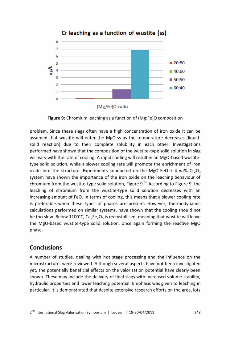
Figure 9: Chromium leaching as a function of (Mg:Fe)O composition
problem. Since these slags often have a high concentration of iron oxide it can be
assumed that wustite will enter the MgO-ss as the temperature decreases (liquid-
solid reaction) due to their complete solubility in each other. Investigations
performed have shown that the composition of the wustite-type solid solution in slag
will vary with the rate of cooling. A rapid cooling will result in an MgO-based wustite-
type solid solution, while a slower cooling rate will promote the enrichment of iron
oxide into the structure. Experiments conducted on the MgO-FeO + 4 wt% Cr2O3
system have shown the importance of the iron oxide on the leaching behaviour of
chromium from the wustite-type solid solution, Figure 9.56 According to Figure 9, the
leaching of chromium from the wustite-type solid solution decreases with an
increasing amount of FeO. In terms of cooling, this means that a slower cooling rate
is preferable when these types of phases are present. However, thermodynamic
calculations performed on similar systems, have shown that the cooling should not
be too slow. Below 1100°C, Ca2Fe2O5 is recrystallised, meaning that wustite will leave
the MgO-based wustite-type solid solution, once again forming the reactive MgO
phase.
Conclusions
A number of studies, dealing with hot stage processing and the influence on the
microstructure, were reviewed. Although several aspects have not been investigated
yet, the potentially beneficial effects on the valorisation potential have clearly been
shown. These may include the delivery of final slags with increased volume stability,
hydraulic properties and lower leaching potential. Emphasis was given to leaching in
particular. It is demonstrated that despite extensive research efforts on the area, lots
2nd International Slag Valorisation Symposium | Leuven | 18-20/04/2011 249
of questions remain. As the leaching behaviour is still the primary cause for
valorisation difficulties, additional research work is expected in the field. It is strongly
believed that a conscious hot stage processing step can both increase slag utilisation
rates and make higher value applications achievable.
References 1. USGS, Mineral Commodity Summaries 2007. In United States Geological Survey: 2007, pp 88-89.
2. ISSF, Crude steel production 2006.
http://www.worldstainless.org/Statistics/Crude/2006.htm (17/07/2007)
3. H. Shen, E. Forssberg and U. Nordström, “Physicochemical and mineralogical properties of
stainless steel slags oriented to metal recovery”. Resour. Conserv. Recy., 40 (3) 245-271 (2004).
4. B. Gorai, R. K. Jana and Premchand, “Characteristics and utilisation of copper slag, a review”.
Resour. Conserv. Recy., (39) 299-313 (2003).
5. ICSG, Release of ICSG 2007 Statistical Yearbook. In International Copper Study Group: 2007.
6. S.-t. Cha and H. Sadrpour, Slag Atomizing Technology (SAT): Strategic management of Electric Arc
Furnace slag. In 2nd global conference and exhibition for the markets, production and processing
technology of slag, Royal Orchid Sheraton Hotel, Bangkok, 2006.
7. M. Kühn, “Visionary outlook towards dry quenching of slags for heat recovery”. In 1st
International Slag Valorisation Symposium, 2009, Leuven. Jones, P.T., Geysen, D., Guo, M. and
Blanpain, B., Eds. pp. 135-142 (2009).
8. J.-W. Moon, Kim. Huyn-Soo and Y. Sasaki, “Energy recuperation from slags”. In 1st International
Slag Valorisation Symposium, 2009, Leuven. Jones, P.T, Geysen, D., Guo, M. and Blanpain, B., Eds.
pp. 143-150 (2009).
9. D. Durinck, F. Engström, S. Arnout, J. Heulens, P. T. Jones, B. Björkman, B. Blanpain and P.
Wollants, “Hot stage processing of metallurgical slags”. Resour. Conserv. Recy., 52 (10) 1121-
1131 (2008).
10. M. Kühn and H. Behmenburg, Decreasing the scorification of chrome, Report EUR 19382, Primary
Steelmaking, European Commission 39, Luxembourg, (2000).
11. M. Kühn, P. Drissen and H. Schrey, “Treatment of liquid steel slags”. In 2nd European slag
conference, 2000, Düsseldorf, Germany,. pp. 123-135 (2000).
12. Sichien J., “Slag-stabilisation-process at Arcelor Gent”. In 5th European slag conference, (2007).
13. P. Drissen and D. Mudersbach, “By-products in Iron and Steelmaking - Troublesome materials or
secondary raw materials?”. In Waste Recovery in Ironmaking and Steelmaking Processes, London,
(2010).
14. U. Fritsching, C. Czisch, L. Schubert, H. Motz, M. Kuehn and D. Mudersbach, “Faserfreie
Zerstäubung von basischer Hochofenschlacke”. Report des Forschungsinstituts, 14 (2) 4/7 (2007).
15. A. Seki, Y. Aso, M. Okubo, F. Sudo and K. Ishizaka, “Development of dusting prevention stabilizer
for stainless steel slags”. Kawasaki Steel Giho, 18 (1) 20-24 (1986).
16. T. A. Branca, V. Colla and R. Valentini, “A way to reduce environmental impact of ladle furnace
slag”. Ironmaking and Steelmaking, 36, 597-602 (2009).
17. D. Durinck, S. Arnout, G. Mertens, E. Boydens, P. T. Jones, J. Elsen, B. Blanpain and P. Wollants,
“Borate distribution in stabilized stainless-steel slag”. J. Am. Ceram. Soc., 91 (2) 548-554 (2008).
18. J. G. Fletcher and F. P. Glasser, “Phase relations in the system CaO-B2O3-SiO2”. J. Mater. Sci., 28
(10) 2677-2686 (1993).
19. D. Durinck. High Temperature Processing of Metallurgical Slags: A Method to Promote Recycling.
Doctoral thesis, K. U. Leuven, 2008.

2nd International Slag Valorisation Symposium | Leuven | 18-20/04/2011 250
20. D. Geysen, S. Huang, P. Lhoëst, J. Van Dyck, Y. Pontikes, D. Durinck, P. T. Jones, B. Blanpain, E.
Nagels, S. Arnout and A. Cotton, Boron in stainless steel slags. In The 6th European Slag
Conference, Madrid, Spain, (2010).
21. X. Wang. Stabilisation by additions and hydraulic properties of high C2S-content stainless steel
slag. Master of Science thesis, K. U. Leuven, (2010).
22. S. N. Ghosh, P. B. Rao, A. K. Paul and K. Raina, “Review. The chemistry of dicalcium silicate
mineral”. J. Mater. Sci., 14 (7) 1554-1566 (1979).
23. A. Ghose, S. Chopra and J. F. Young, “Microstructural characterisation of doped dicalcium silicate
polymorphs”. J. Mater. Sci., 18 (10) 2905-2914 (1983).
24. G. C. Lai, T. Nojiri and K. i. Nakano, “Studies of the stability of β-Ca2SiO4 doped by minor ions”.
Cem. Concr. Res., 22 (5) 743-754 (1992).
25. J. Geiseler, “Properties of iron and steel slags regarding their use”. In 6th Conference on molten
slags, fluxes and salts, (2000).
26. D. V. Lopatin and V. M. Chizhikova, “The new stability criterion of crystal-chemical stabilisation of
β-C2S”. In Advances in metallurgical processes and materials, 2007, Dnepropetrovsk, Ukraine. pp.
481-482, (2007).
27. Q. Yang, L. Nedar, F. Engström and M. He, “Treatments of AOD slag to produce aggregates for
road construction”. In Aistech 2006, 2006, Ohio, USA. pp. 573-583, (2006).
28. Q. Yang, F. Engström, B. Björkman and D. Adolfsson, “Modification study of a steel slag to
prevent the slag disintegration after metal recovery and to enhance slag utilisation”. In 8th
International Conference on Molten Slags, Fluxes and Salts – MOLTEN 2009, 2009, Santiago,
Chile. Mario Sánchez, Roberto Parra, Gabriel Riveros and Carlos Díaz, Eds., (2009)
29. F. Bodénan, M. Gautier, N. Rafai, J. Poirier, P. Piantone, G. Franceschini, I. Moulin, P. Chaurand
and J. Ros, “Phosphorus speciation in dicalcium silicate polymorphs of basic oxygen furnace
(BOF) slag”. Déchets Sciences et Techniques, 57 (4) (2010).
30. M. Gautier, J. Poirier, G. Franceschini, F. Bodeman and M. Gautier, “Influence of the cooling
conditions on the nature and the size of the mineral phase in a Basic Oxigen Furnace (BOF) slag”.
Déchets Sciences et techniques, 57 (8) (2010).
31. T. W. Parker and J. F. Ryder, “Investigations on ‘falling’ blast furnace slags”. Journal of the Iron
and Steel Institute, 11, 21-51 (1942).
32. M. Guo, D. Durinck, P. T. Jones, G. Heylen, R. Hendrickx, R. Baeten, B. Blanpain and P. Wollants,
“EAF stainless steel refining - Part I: Observational study on chromium recovery in an eccentric
bottom tapping furnace and a spout tapping furnace”. Steel Res. Int., 78 (2) 117-124 (2007).
33. N. Sakamoto, “Effects of MgO based glass addition on the dusting of stainless steel slag
(development of control process of stainless steel slag dusting-3)”. Current Advance in Materials
and Processes, 14 (4) 939 (2001).
34. S. Kitamura and N. Maruoka “Modification of stainless steel refining slag through mixing with
nonferrous smelting slag”. In First International Slag Valorisation Symposium, 2009, Leuven,
Belgium. Jones, P. T., Geysen, D., Guo, M. and Blanpain, B., Eds., (2009).
35. H. Kagechika, “Recent Progress and Future Trends in the Research and Development of Steel”.
NKK Tech. Rev., 88 (2003).
36. T. Takahashi and K. Yabuta, “New applications for iron and steelmaking slags”. NKK Tech. Rev.,
87, 38-44 (2002).
37. Y. Yao, K. Matsubara and T. Takahashi, “Fertilizer effectiveness of potassium silicate fertilizer
produced with steelmaking slag”. Nippon Dojo Hiryogaku Zasshi, 72 (1) 25-32 (2001).
38. D. Mudersbach, M. Kühn, J. Geisler and K. Koch, “Chrome immobilisation in EAF-slags from high-
alloy steelmaking: tests at FEhS institute and development of an operational slag treatment
process”. In First International Slag Valorisation Symposium, 2009, Leuven, Belgium. Jones, P. T.,
Geysen, D., Guo, M. and Blanpain, B., Eds., (2009)

2nd International Slag Valorisation Symposium | Leuven | 18-20/04/2011 251
39. G. Stubbe, G. Harp and M. Sedlemeier, “New Technology for Recovery of Chromium from EAF
Stainless Steelmaking Slag”. In Waste Recovery in Ironmaking and Steelmaking Processes,
London, (2010).
40. J. Stark, A. Müller, R. Schrader and K. R. Rumpler, “Contributions to active belite cement, part 2:
Influence of cooling conditions of cement strength”. Silikattechnik, 31 (2) 50-52 (1980).
41. Q. Yang, F. Engström, M. Tossavainen and M. He, “AOD slag treatments to recover metal and to
prevent slag dusting”. In 7th Nordic-Japan symposium on science and technology of process
metallurgy, (2005).
42. L. Kriskova, Υ. Pontikes, Κ. Lietaert, L. Pandelaers, Ö. Cizer, D. Geysen, P. T. Jones, B. Blanpain and
K. Van Balen, “Effect of chemical composition and cooling rate on mineralogy and hydraulic
properties of synthetic AOD slag”. In to be presented in 12th International Conference and
Exhibition of the European Ceramic Society, Stockholm, Sweden, (2011).
43. Q. Romera, Kühn, Behmenburg and D. Capodilupo, Decreasing the scorification of chrome. In
Primary Steelmaking, European Commission (Luxembourg): p 39. (2000).
44. J. A. Meima, R. D. Van Der Weijden, T. T. Eighmy and R. N. J. Comans, “Carbonation processes in
municipal solid waste incinerator bottom ash and their effect on the leaching of copper and
molybdenum”. Applied Geochemistry, 17 (12) 1503-1513 (2002).
45. K. J. Reddy, S. P. Gloss and L. Wang, “Reaction of CO2 with alkaline solid wastes to reduce
contaminant mobility”. Water Research, 28 (6) 1377-1382 (1994).
46. P. Chaurand, J. Rose, V. Briois, L. Olivi, J. L. Hazemann, O. Proux, J. Domas and J. Y. Bottero, “
Environmental impacts of steel slag reused in road construction: A crystallographic and
molecular (XANES) approach”. Journal of Hazardous Materials, 139 (3) 537-543 (2007).
47. P. Drissen, “Binding of trace elements in steel slags”. In 5th European Slag Conference (Euroslag),
2007, Luxembourg, Luxembourg, (2007).
48. C. E. Halim, S. A. Short, J. A. Scott, R. Amala and G. Lowc, “Modelling the leaching of Pb, Cd, As,
and Cr from cementitious waste using PHREEQC”. Journal of Hazardous Materials, A (125) 45–61
(2005).
49. P. Van Herck, B. Van der Bruggen, G. Vogels and C. VandeCasteele, “Application of computer
modelling to predict the leaching behaviour of heavy metals from MSWI fly ash and comparison
with a sequential extraction method”. Waste Management, 20, 203-210 (2000).
50. M. B. Parsons, D. K. Bird, M. T. Einaudi and C. N. Alpers, “Geochemical and mineralogical controls
on trace element release from the Penn Mine base-metal slag dump, California”. Applied
Geochemistry, 16, 1567–1593 (2001).
51. J. S. Geelhoed, J. C. L. Meeussen, S. Hillier, D. G. Lumsdon, R. P. Thomas, J. G. Farmer and E.
Paterson, “Identification and geochemical modeling of processes controlling leaching of Cr(VI)
and other major elements from chromite ore processing residue”. Geochim. Cosmochim. Acta,
66 (22) 3927-3942 (2002).
52. M. Tossavainen and E. Forssberg, “Leaching behaviour of rock material and slag used in road
construction - a mineralogical interpretation”. Steel Research, 71 (11) 442-448 (2000).
53. M. Tossavainen, F. Engström, Q. Yang, N. Menad, M. L. Larsson and B. Björkman, “Characteristics
of steel slag under different cooling conditions”. Waste Management, 27, 1335-1344 (2007).
54. F. Engström. Licentiate Thesis: Mineralogical Influence of Different Cooling Conditions on
Leaching Behaviour of Steelmaking Slags. Luleå University of Technology, Luleå, Sweden, (2007).
55. M. Loncnar, M. Zupančic, P. Bukovec and A. Jakli, “The effect of water cooling on the leaching
behavioue of EAF slag from stainless steel production”. Materiali in tehnologije / Materials and
technology, 43 (6) 315-321 (2009).
56. F. Engström, “Doctoral thesis: Mineralogical influence on leaching behaviour of steelmaking
slags, A Laboratory Investigation”. Luleå, Sweden. Luleå University of Technology (2011).