slag adjuster
DESCRIPTION
Slag adjuster design manualTRANSCRIPT


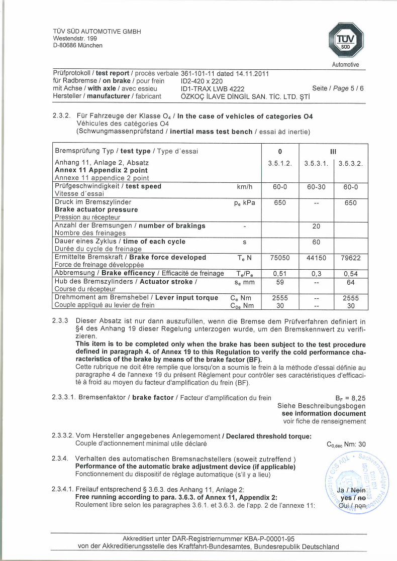


Information Document TRAX LWB 4222
TRAILER AXLE AND BRAKE INFORMATION DOCUMENT WITH RESPECT
TO THE ALTERNATIVE TYPE I AND TYPE III PROCEDURE
(according to ECE R 13, Annex 11 – Appendix 5)
1. GENERAL
1.1. Name and address of axle or vehicle manufacturer:
ÖZKOÇ İLAVE DİNGİL SAN. TİC. LTD. ŞTİ
OSB 13.SOK NO 5 SELÇUKLU/KONYA/TÜRKİYE
2. AXLE DATA
2.1. Manufacturer (name and address): .................................................................... see 1.1.
2.2. Type/variant: ............................................................................................. TRAX LWB
2.3. Axle identifier: ID1- ........................................................................ TRAX LWB 4222
2.4. Test axle load (Fe): ID3- ................................................................................ 14715 daN
2.5. Wheel and brake data according to the following figure 1A:
FIGURE 1A
Permitted range:
315/80R22,5 TWIN TYRE
D (mm) E (mm) G (mm) R (mm) X (mm)
Min 285,5 Min39 Min 10 Min 500 mm Min 294
385/65R22,5 SINGLE TYRE
D (mm) E (mm) G (mm) R (mm) X (mm)
Min 285,5 Min39 Min 10 Min 500 mm Min 294

3. BRAKE
3.1. General information
3.1.1. Make: ............................................................................................................ ÖZKOÇ
3.1.2. Manufacturer (name and address): .................................................................... see 1.1.
3.1.3. Type of brake (e.g. drum / disc): ............................................................... Drum Brake
3.1.3.1. Variant (e.g. S-cam, single wedge etc.): .................................................... S-cam brake
3.1.4. Brake identifier: ID2- ..................................................................................... 420*220
3.1.5. Brake data according to the following figure 2A:
FIGURE 2A
ae
(mm)
he
(mm)
ce
(mm)
de
(mm)
ee
(mm)
α0e
(°)
α1e
(°)
Be
(mm)
re
(mm)
Ae
(cm2)
S1e
(mm)
S2e
(mm)
S3e
(mm)
163,7 317,7 33 42 14 114 70 220 210 1700 11,57 17,22 11,57
3.1.6. Brake factor BF: ...................................................................................................... 8,25

3.2. Drum brake data
3.2.1. Brake adjustment device (external/integrated): ................................................ external
3.2.1.1. 3.2.1.2. 3.2.1.3. 3.2.1.4. 3.2.1.5. 3.2.1.6.
Alternative Manufacturer
and address Make Type Version
Effective
length of the
cam shaft
A HALDEX HALDEX S-ABA 80022 0 640 mm
3.2.2. Declared maximum brake input torque Cmax: ................................................. 2800 Nm
for calculation (pm= 650 kPa) ........................................................................ 2560 Nm
3.2.3. Mechanical efficiency: = .................................................................................... 0,9
3.2.4. Declared brake input threshold torque C0,dec: .................................................... 30 Nm
3.2.5. Effective length of the cam shaft: ................................................................... see 3.2.1.
3.3. Brake drum
3.3.1. Max diameter of friction surface (wear limit) .................................................. 420 mm
3.3.2. Base material: .................................................................................................. Cast iron
3.3.3. Declared mass: ...................................................................................................... 66 kg
3.3.4. Nominal mass: ...................................................................................................... 66 kg
3.3.5. Permitted range of the brake drum mass: ............................................................. 68 kg
3.3.6. Brake drum ................................................................................................. without hub
3.4. Brake lining
3.4.1. Manufacturer and address .......................... EREN FREN VE DEBRİYAJ BALATALARI
3.4.2. Make .................................................................................................................... EREN
3.4.3. Type ....................................................................................................... M761-4687-220
3.4.4. Identification (type identification on lining) .......................................... M761-4687-220
3.4.5. Minimum thickness (wear limit) .......................................................................... 5 mm
3.4.6. Method of attaching friction material to brake shoe:........................................... riveted
3.4.6.1. Worst case of attachment (in the case of more than one): ........................ not applicable
3.4.6.2. Range of the weight of the brake shoes: ............................................................... 6,6 kg
3.4.6.3. Base material of the brake shoes: ............................................................................ steel