review 2015-11 lvb-lvh
TRANSCRIPT
1
LVB-LVH
REVIEW 2015-11 OPERATING INSTRUCIONS AND SPARE PARTS
2
This handbook describes the use, maintenance instructions
and spare parts supplied for the indicated plough.
The farming implement known as “plough“ is designed to
work the soil, linked to a tractor with lift and universal 3-point
coupling.
Regular and satisfactory operation together with economic and long lasting use of the implement depends on compliance with the instructions given in this handbook. It is, therefore, advisable to strictly comply with the following instructions in order to prevent faults which could jeopardise the correct and long-lasting operation of the implement.
Compliance with the instructions in this handbook is also
important since the Manufacturer declines all and every
responsibility caused by negligence and failure to comply
with these instructions.
The Manufacturer shall, however, remain at the customer’s
disposal for immediate and thorough assistance together with
anything else that may be required in order to ensure the correct
operation and maximum efficiency of the implement. The
Manufacturer reserves the right to make any modifications and
improvements to the implement, as may be considered
opportune, without being obliged to immediately inform the user.
CONTENTS
1. Safety provisions .................................................. 3
2. Descriptions .......................................................... 5
3. “Varilabor” ............................................................. 6
4. Protection systems ............................................... 6
5. Set to work ............................................................. 7
5.1 Moulboards ................................................... 7
5.2 Hitching to the tractor .................................. 8
5.3 Alignment ...................................................... 8
5.4 Front furrow width ........................................ 9
5.5 Other adjustments ...................................... 10
6. Ploughing depth ................................................. 11
7. Transport and parking ........................................ 12
8. Maintenance ........................................................ 13
9. Optional equipment............................................. 14
10. Spare parts .......................................................... 15
3
1. SAFETY PROVISIONS
1.- Comply with the instructions given by the danger signals exposed in this handbook (Fig.1) and affixed to the plough itself. 2.- Operations and adjustments to the implement must always be carried out when the engine is off and the tractor braked. 3.- It is absolutely forbidden to carry passengers or animals on the plough. 4.- It is absolutely forbidden for persons without a driving license, inexpert persons or those in precarious health conditions to drive the tractor with the plough mounted. 5.- Strictly comply with all the recommended accident preventing measures described in this handbook. 6.- Assembly of an implement on the tractor will shift the weights on the axles. 7.- Before starting the tractor and plough, always check that all safety devices guarding transport and use are in perfect conditions. 8.- The instructions labels affixed to the plough give useful advice on how to prevent accidents. 9.- Always comply with the highway code in force in your country when travelling on public roads. 10.- Comply with the maximum permissible weight on the axle of the tractor, the total adjustable weight, transport regulations and the highway code. 11.- Always become familiar with the controls and their operation before starting work.
12.- Take the utmost care during the plough coupling and release phases. 13.- Never ever leave the driving seat whilst the tractor is moving. 14.- Remember that the road holding, steering and breaking capacity may be notably influenced by the presence of a mounted implement. 15.- It is absolutely forbidden to stand within the operative range of the plough. 16.- Before leaving the tractor, lower the mounted plough coupled to the lift unit, stop the engine, engage the hand brake and remove the ignition key from the control panel. 17.- The category of the implement coupling pins must correspond to that of the lift coupling. 18.- Take care when working close to the lift links. This is a very dangerous area. 19.- It is absolutely forbidden to stand between the tractor and the plough, to manoeuvre the outside lift control. 20.- Set the control lever of the hydraulic lift to the locked position during road transport with the plough mounted. 21.- The spare parts must correspond to the requirements established by the Manufacturer. Use only genuine spare parts. 22.- The safety transfers must always be perfectly visible. They must be kept clean and should be replaced if they become illegible. Replacements are available on request from your local dealer. 23.- The instruction manual must be kept for as long as the machine lasts.
4
Fig.1
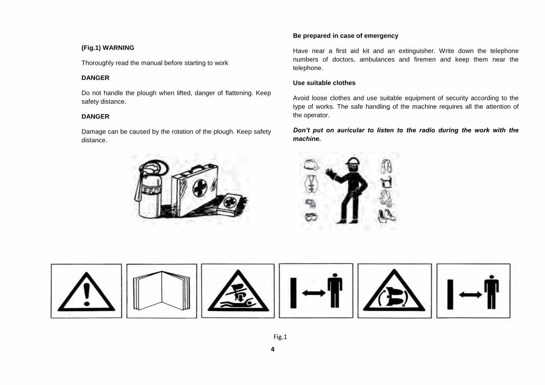
(Fig.1) WARNING
Thoroughly read the manual before starting to work
DANGER
Do not handle the plough when lifted, danger of flattening. Keep
safety distance.
DANGER
Damage can be caused by the rotation of the plough. Keep safety
distance.
Be prepared in case of emergency
Have near a first aid kit and an extinguisher. Write down the telephone
numbers of doctors, ambulances and firemen and keep them near the
telephone.
Use suitable clothes
Avoid loose clothes and use suitable equipment of security according to the
type of works. The safe handling of the machine requires all the attention of
the operator.
Don’t put on auricular to listen to the radio during the work with the
machine.

5
IDENTIFICATION PLATE (2)
1
TECHNICAL DATA
1
5
4
3
8 7
6
10
9
2. DESCRIPTION AND TECHNICAL DATA
1. HEADSTOCK 2. IDENTIFICATION PLATE 3. HYDRAULIC TURN 4. CROSS SHAFT 5. MOULBOARD 6. SHIN PIECE 7. SHARE POINT 8. SHARE 9. FRAME 10. BEAM
REMARK: The construction number that is engraved
in the identification plate must be coincident with the
number engraved on the headstock support.
6
Fig.3
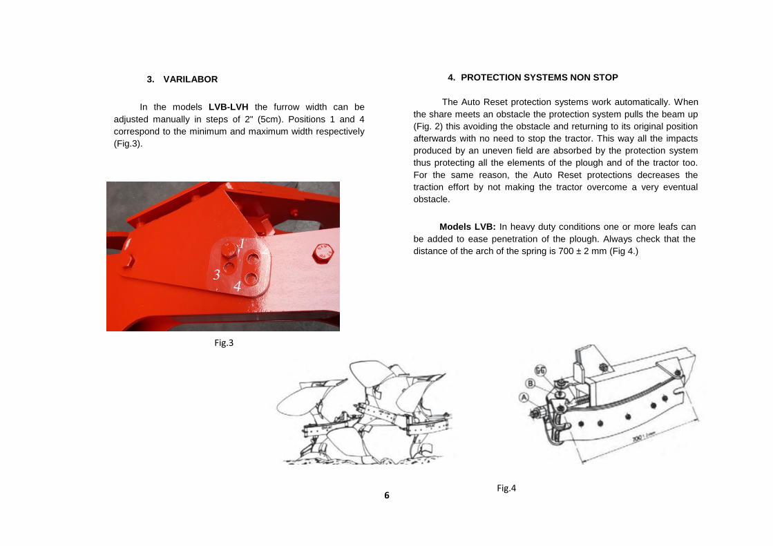
3. VARILABOR
In the models LVB-LVH the furrow width can be
adjusted manually in steps of 2" (5cm). Positions 1 and 4
correspond to the minimum and maximum width respectively
(Fig.3).
4. PROTECTION SYSTEMS NON STOP
The Auto Reset protection systems work automatically. When
the share meets an obstacle the protection system pulls the beam up
(Fig. 2) this avoiding the obstacle and returning to its original position
afterwards with no need to stop the tractor. This way all the impacts
produced by an uneven field are absorbed by the protection system
thus protecting all the elements of the plough and of the tractor too.
For the same reason, the Auto Reset protections decreases the
traction effort by not making the tractor overcome a very eventual
obstacle.
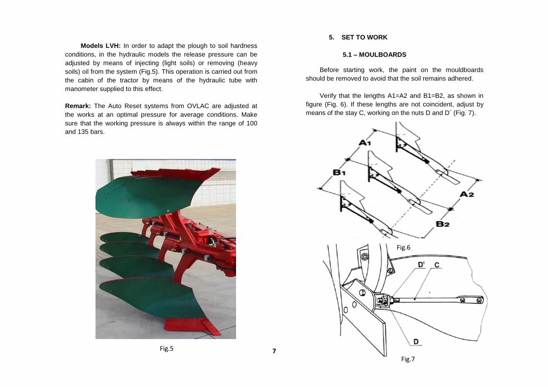
Models LVB: In heavy duty conditions one or more leafs can
be added to ease penetration of the plough. Always check that the
distance of the arch of the spring is 700 ± 2 mm (Fig 4.)
Fig.4
7
Models LVH: In order to adapt the plough to soil hardness
conditions, in the hydraulic models the release pressure can be
adjusted by means of injecting (light soils) or removing (heavy
soils) oil from the system (Fig.5). This operation is carried out from
the cabin of the tractor by means of the hydraulic tube with
manometer supplied to this effect.
Remark: The Auto Reset systems from OVLAC are adjusted at
the works at an optimal pressure for average conditions. Make
sure that the working pressure is always within the range of 100
and 135 bars.
Fig.7
Fig.6
Fig.5
5. SET TO WORK
5.1 – MOULBOARDS
Before starting work, the paint on the mouldboards
should be removed to avoid that the soil remains adhered.
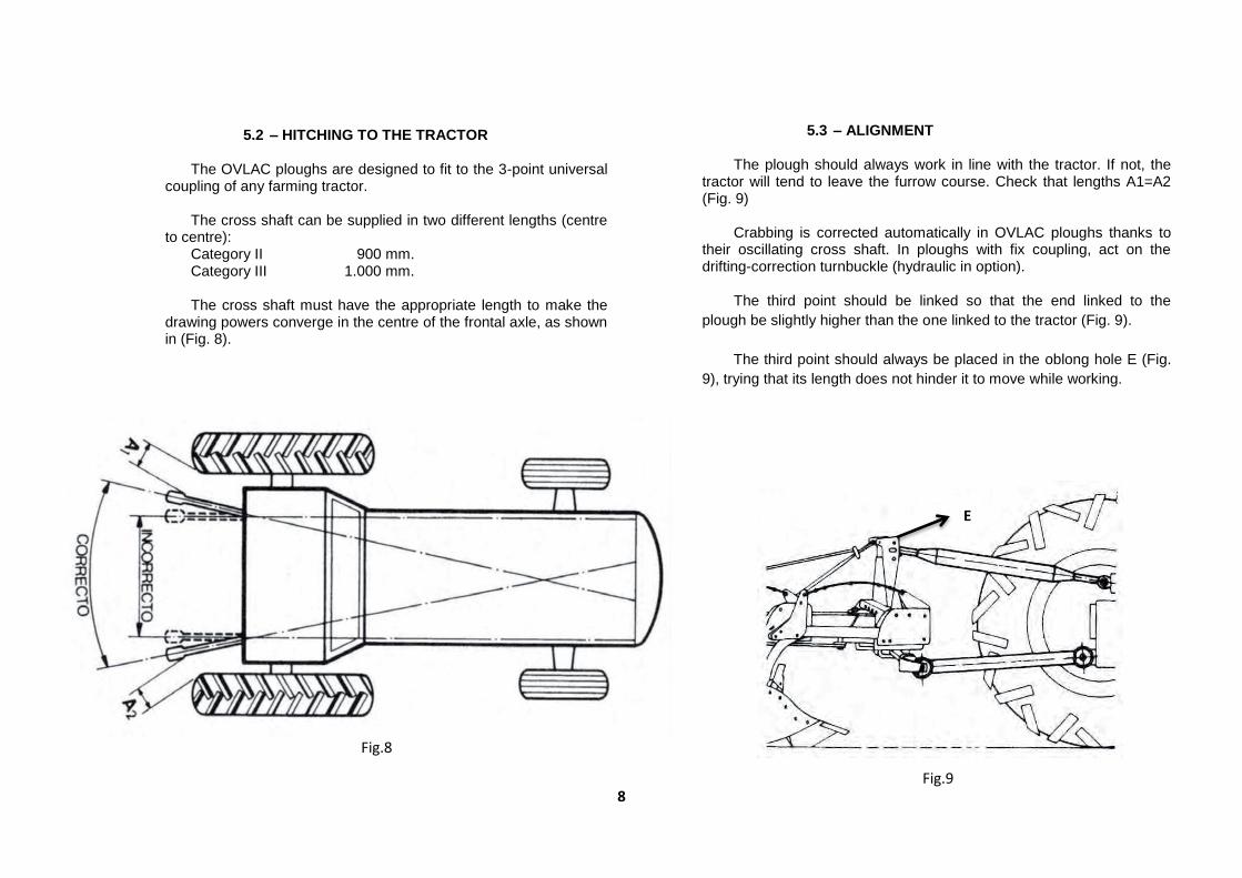
Verify that the lengths A1=A2 and B1=B2, as shown in
figure (Fig. 6). If these lengths are not coincident, adjust by
means of the stay C, working on the nuts D and D´ (Fig. 7).
8
Fig.8
Fig.9
E
5.2 – HITCHING TO THE TRACTOR
The OVLAC ploughs are designed to fit to the 3-point universal coupling of any farming tractor.
The cross shaft can be supplied in two different lengths (centre to centre): Category II 900 mm. Category III 1.000 mm.
The cross shaft must have the appropriate length to make the drawing powers converge in the centre of the frontal axle, as shown in (Fig. 8).
5.3 – ALIGNMENT
The plough should always work in line with the tractor. If not, the tractor will tend to leave the furrow course. Check that lengths A1=A2 (Fig. 9)
Crabbing is corrected automatically in OVLAC ploughs thanks to
their oscillating cross shaft. In ploughs with fix coupling, act on the drifting-correction turnbuckle (hydraulic in option).
The third point should be linked so that the end linked to the
plough be slightly higher than the one linked to the tractor (Fig. 9).
The third point should always be placed in the oblong hole E (Fig.
9), trying that its length does not hinder it to move while working.

9
Fig.10
T
Fig.12
Fig.11
5.4 – FRONT FURROW WIDTH
The width of the first furrow is adjusted by acting on the screw
C (Fig. 10), this moving the headstock laterally until all observations
in (Fig.11 y 12) are applied.
10
Fig.15
Fig.14
Fig.13
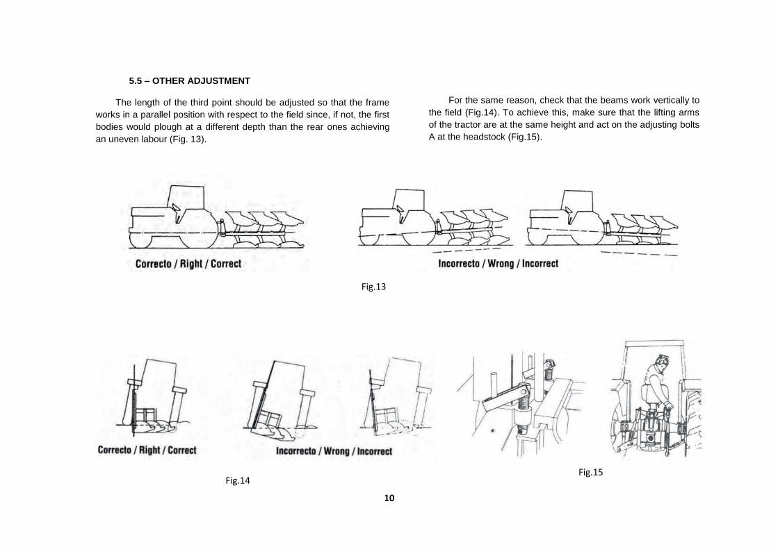
5.5 – OTHER ADJUSTMENT
The length of the third point should be adjusted so that the frame
works in a parallel position with respect to the field since, if not, the first
bodies would plough at a different depth than the rear ones achieving
an uneven labour (Fig. 13).
For the same reason, check that the beams work vertically to
the field (Fig.14). To achieve this, make sure that the lifting arms
of the tractor are at the same height and act on the adjusting bolts
A at the headstock (Fig.15).
11
Fig.16
A
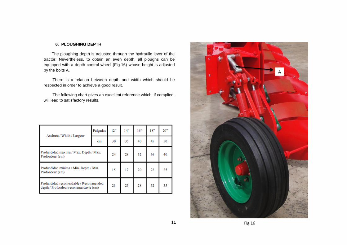
6. PLOUGHING DEPTH
The ploughing depth is adjusted through the hydraulic lever of the
tractor. Nevertheless, to obtain an even depth, all ploughs can be
equipped with a depth control wheel (Fig.16) whose height is adjusted
by the bolts A.
There is a relation between depth and width which should be
respected in order to achieve a good result.
The following chart gives an excellent reference which, if complied,
will lead to satisfactory results.
12
Fig.18
B
Fig.16
B
D
C
E E
Fig.19
Fig.17
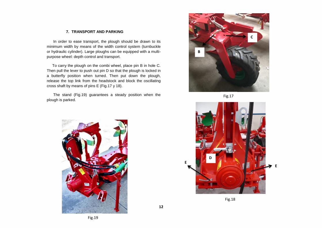
7. TRANSPORT AND PARKING
In order to ease transport, the plough should be drawn to its
minimum width by means of the width control system (turnbuckle
or hydraulic cylinder). Large ploughs can be equipped with a multi-
purpose wheel: depth control and transport.
To carry the plough on the combi wheel, place pin B in hole C.
Then pull the lever to push out pin D so that the plough is locked in
a butterfly position when turned. Then put down the plough,
release the top link from the headstock and block the oscillating
cross shaft by means of pins E (Fig.17 y 18).
The stand (Fig.19) guarantees a steady position when the
plough is parked.
13
8. MAINTENANCE
Retighten all bolts and nuts after the first 8 hours of work, specially
the ones of mouldboards, shares and points. Henceforth, check every 100
hours of work. When putting the plough away, clean and grease
thoroughly the mouldboards to prevent from rusting.
Lubrication: grease the greaser.
Safe maintenance
Be used to the maintenance procedures before carrying out the
works. The working zone must be clean and dry. Don’t carry out any work
of lubrication, repair or adjust with the motor enabled. Keep the hands,
feet and clothes always far from movable components. Turn all the
controls off, to alleviate the pressure. All the components must be in good
state and correctly installed. Repair damages immediately. Change any
worn away or broken pieces. Maintain all the components of the machine
clean of fat, oil and accumulated dirt. Because of being dragged
equipment, disconnect the cable groups of the tractor before making
works of weld in the machine.
Take care of the leaks of high pressure
The fluids that escape of the system can have as much force that
they can penetrate the skin, causing serious injuries. Therefore, it is
essential to leave the system without pressure before relaxing or
disconnecting any pipe and make sure that all the connections and the
hydraulic parts they are well tight before applying pressure to the system.
In order to locate a hydraulic oil leak, use a piece of cardboard that is put
on the connections. Do not approach the hands and the body to a leak of
high pressure. If, in spite of this precaution, it happens an accident, go
immediately to a doctor who should eliminate surgically the fluid within few
hours to avoid gangrene. The doctors who do not have experience in
dealing with these type injuries can go to a specialized medical centre.
Storage of the hydraulic sleeves.
IMPORTANT: maintain the plugs clean. The abrasive particles, like
the sand or the metallic shaving, can damage the oil seals, shirts and
cylinders, causing internal leaks. Once disconnected of the tractor, make
sure that they are not in contact with the ground
14
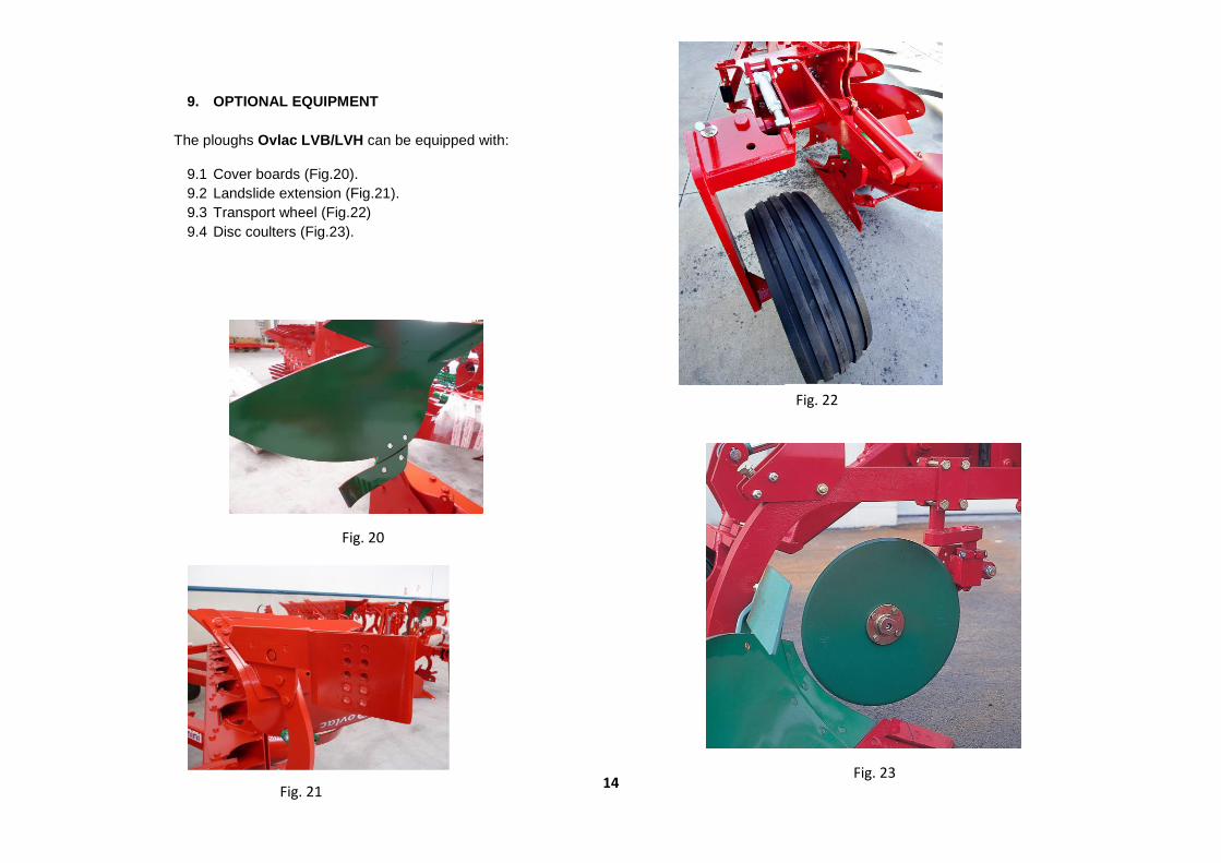
9. OPTIONAL EQUIPMENT
The ploughs Ovlac LVB/LVH can be equipped with:
9.1 Cover boards (Fig.20).
9.2 Landslide extension (Fig.21).
9.3 Transport wheel (Fig.22)
9.4 Disc coulters (Fig.23).
Fig. 20
Fig. 21 Fig. 23
Fig. 22
15
CONTENT
HEADSTOCK ........................................................................ 16
FRAME .................................................................................. 18
FRAME SUPPORT ................................................................ 20
MODULE ............................................................................... 22
ROLLOVER ........................................................................... 23
BEAM SUPPORT LVH .......................................................... 24
BEAM SUPPORT LVB ......................................................... 26
HYDRAULIC SYSTEM .......................................................... 28
VARYWIDTH SYSTEM ......................................................... 30
MEMORY .............................................................................. 31
HYDRAULIC FIRST BODY ADJUSTMENT 600-1000 ......... 33
BODIES ................................................................................. 35
SKIMMERS ........................................................................... 43
COVER BOARDS ................................................................. 45
LANSLIDE EXTENSION ....................................................... 47
SUPLEMENT EXTENSION MOULBOARD .......................... 48
SUPLEMENT EXPANDER GROOVE ................................... 49
FAST HITCH ......................................................................... 50
DISC COULTERS 20” ........................................................... 51
DISC COULTERS 20” NON STOP ....................................... 53
WHEELS ............................................................................... 55
10. SPARE PARTS
Spare parts should always be ordered from your dealer and should
always include the following indications:
- Type, model and serial number of the plough. These data are
punched on the identification plate with which every plough is equipped.
- Code number of the required spare part. This will be found in the
attached spare parts list.
- Description of the part and required quantity.
- Means of delivery. Transport expenses shall always be at the
consignor's charge.
- NOTE: The terms Right and Left indicated on the descriptions, refer to
the plough when viewed from the rear. The spare parts components of
waste equipment, as shares, mouldboards, etc., are considered right if
they are mounted on a body which spills the soil to the right side and
viceversa.
- Note about the warranty: The orders of spare parts in warranty should
always be clearly specified. The Manufacturer will always sentence if
the spare parts are warranted in their replacement.
- Moreover, the warranty is suppressed if:
- The plough is repaired without authorisation from the
Manufacturer, or spurious spare parts, and inadequate bolts are
mounted.
- The plough has been used beyond the specified power limit, or
anomalous manoeuvres and operations have been made.

HEADSTOCK
16

17
REFERENCIA DESCRIPCIÓN REFERENCIA DESCRIPCIÓN
15001098 LLAVE 32-38 62000004 PASADOR ANILLA 10 ZINC.
15008991 EJE CABEZAL 120 (PLACA 176mm.) 62000030 PASADOR ELAST.DIN-1481 10* 80 ZINC.
15010901 TUERCA EJE CABEZAL 120 (D/06) 62000037 PASADOR ANILLA 4,5 ZINC.
53000004 ENGRASADOR AC° DIN-71412 8*125 63000073 RODAM.ANTER.30218 F (C-120/D-03)
53000369 SOPORTE LATIG.TORRETA 2 HUECOS ZINC. 63000074 RODAM.POST.32021 XF (C-120/D-03)
53000450 JUNTA TORICA 160-3 85028901 SEP.B.P.32/20* 42mm.
60000043 TORN.EXAG.DIN-931 8* 55 8.8 ZINC. 90006900 BULON D=28*130mm.BALANC.CAT.II ZINC.
60000074 TORN.EXAG.DIN-931 14* 80 8.8 ZINC. 90007900 HUSILLO TOPE 185mm.
60000084 TORN.EXAG.DIN-931 16*100 8.8 90075902 BULON D=25*110mm.3er.PTO.CAT.II ZINC.
60000131 TUER.AUTO.DIN-980 8 8.8 ZINC. 90095900 MANILLA TOPE ZINC.
60000140 TUER.AUTO.DIN-980 10 8.8 ZINC. 93002900 PLACA PORTABALANC.40mm.
60000143 TUER.AUTO.DIN-980 16 8.8 ZINC. 93003900 BALANC.40mm.CAT-II
60000218 TORN.ALLEN DIN-913 12* 16 12.9 95001901 CABEZAL 120 (D/O4)
60000339 TORN.EXAG.DIN-933 10* 30 8.8 ZINC. 95008901 BULON D=29,6*123mm.INF.VOLTEO 110(D/07)/120
61000006 ANILLO ELASTICO DIN-471 35 95009901 ARAND.POST.120 (D/03)
61000031 ARAND.STANDAR S/BISEL CL-26 ZINC.(50x27x3) 95011920 CONTRATUERCA EJE CABEZAL 110 (D-07)/120/150
HEADSTOCK
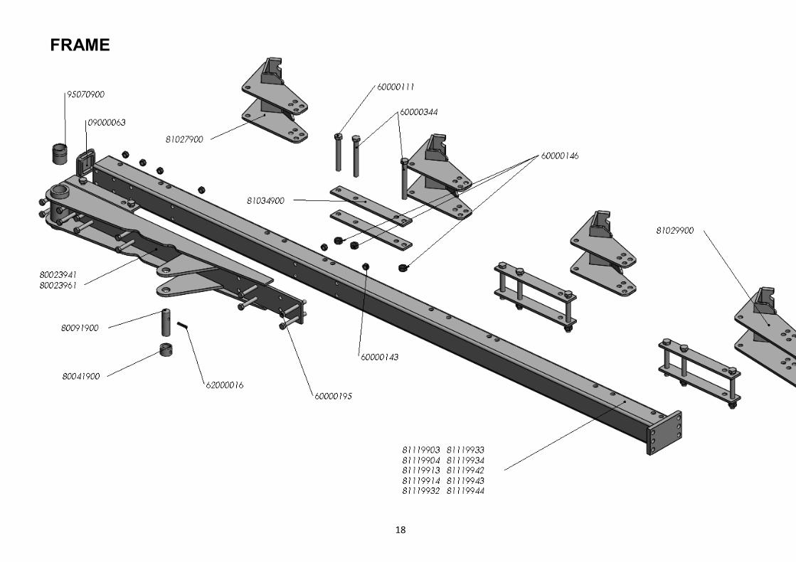
FRAME
18
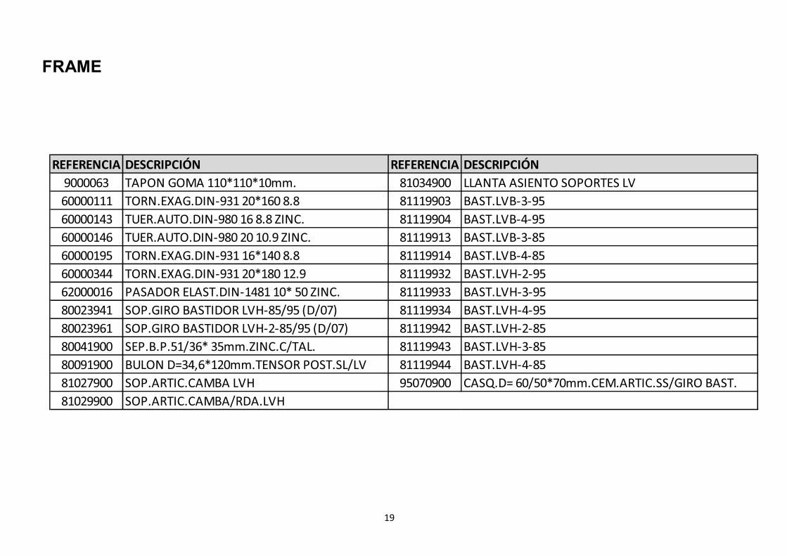
FRAME
19
REFERENCIA DESCRIPCIÓN REFERENCIA DESCRIPCIÓN
9000063 TAPON GOMA 110*110*10mm. 81034900 LLANTA ASIENTO SOPORTES LV
60000111 TORN.EXAG.DIN-931 20*160 8.8 81119903 BAST.LVB-3-95
60000143 TUER.AUTO.DIN-980 16 8.8 ZINC. 81119904 BAST.LVB-4-95
60000146 TUER.AUTO.DIN-980 20 10.9 ZINC. 81119913 BAST.LVB-3-85
60000195 TORN.EXAG.DIN-931 16*140 8.8 81119914 BAST.LVB-4-85
60000344 TORN.EXAG.DIN-931 20*180 12.9 81119932 BAST.LVH-2-95
62000016 PASADOR ELAST.DIN-1481 10* 50 ZINC. 81119933 BAST.LVH-3-95
80023941 SOP.GIRO BASTIDOR LVH-85/95 (D/07) 81119934 BAST.LVH-4-95
80023961 SOP.GIRO BASTIDOR LVH-2-85/95 (D/07) 81119942 BAST.LVH-2-85
80041900 SEP.B.P.51/36* 35mm.ZINC.C/TAL. 81119943 BAST.LVH-3-85
80091900 BULON D=34,6*120mm.TENSOR POST.SL/LV 81119944 BAST.LVH-4-85
81027900 SOP.ARTIC.CAMBA LVH 95070900 CASQ.D= 60/50*70mm.CEM.ARTIC.SS/GIRO BAST.
81029900 SOP.ARTIC.CAMBA/RDA.LVH
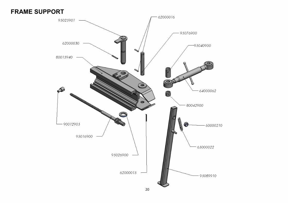
FRAME SUPPORT
20

21
REFERENCIA DESCRIPCIÓN
60000210 TUER.AUTO.DIN-985 1" SAE 8.8
62000015 PASADOR ELAST.DIN-1481 8* 80 ZINC.
62000016 PASADOR ELAST.DIN-1481 10* 50 ZINC.
62000030 PASADOR ELAST.DIN-1481 10* 80 ZINC.
64000062 TENSOR C/ROT.D=35 30386 ZINC.
65000022 MUELLE TRACCIÓN 225/175*26*5 EECC 195mm
80015940 SOP.BASTIDOR SL/LV-600mm.(D/07)
80042900 SEP.B.P.51/36* 35mm.ZINC.
90012905 TUERCA AJUSTE BASTIDOR EJE 110
95016900 HUSILLO AJUSTE BASTIDOR 600mm
95025901 BULON D=50*307mm.GIRO BAST.S (H/03)/FB(H/07)/SL/LV
95026900 ARAND.P/BULON GIRO BASTIDOR
95040900 SEP.B.P.51/36* 92mm.ZINC.
95076900 BULON D=35*262mm.TENSOR ANTER.S (H/03)/SL/LV (D/03
95089910 PEON REVERSIBLE D/70cm.SL (D/07)
FRAME SUPPORT
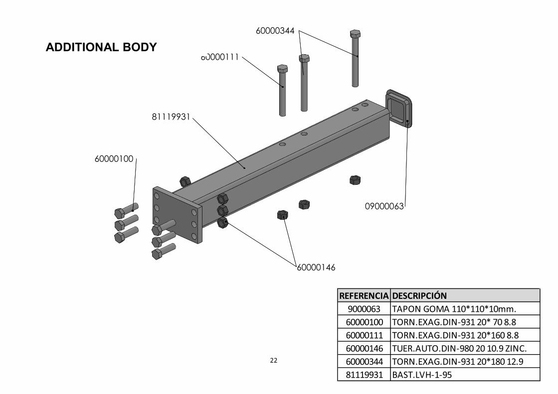
ADDITIONAL BODY
REFERENCIA DESCRIPCIÓN
9000063 TAPON GOMA 110*110*10mm.
60000100 TORN.EXAG.DIN-931 20* 70 8.8
60000111 TORN.EXAG.DIN-931 20*160 8.8
60000146 TUER.AUTO.DIN-980 20 10.9 ZINC.
60000344 TORN.EXAG.DIN-931 20*180 12.9
81119931 BAST.LVH-1-95
22
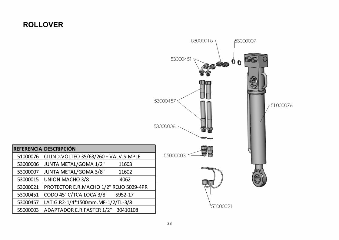
ROLLOVER
REFERENCIA DESCRIPCIÓN
51000076 CILIND.VOLTEO 35/63/260 + VALV.SIMPLE
53000006 JUNTA METAL/GOMA 1/2" 11603
53000007 JUNTA METAL/GOMA 3/8" 11602
53000015 UNION MACHO 3/8 4062
53000021 PROTECTOR E.R.MACHO 1/2" ROJO 5029-4PR
53000451 CODO 45° C/TCA.LOCA 3/8 S952-17
53000457 LATIG.R2-1/4*1500mm.MF-1/2/TL-3/8
55000003 ADAPTADOR E.R.FASTER 1/2" 30410108
23

BEAM SUPPORT LVH
24
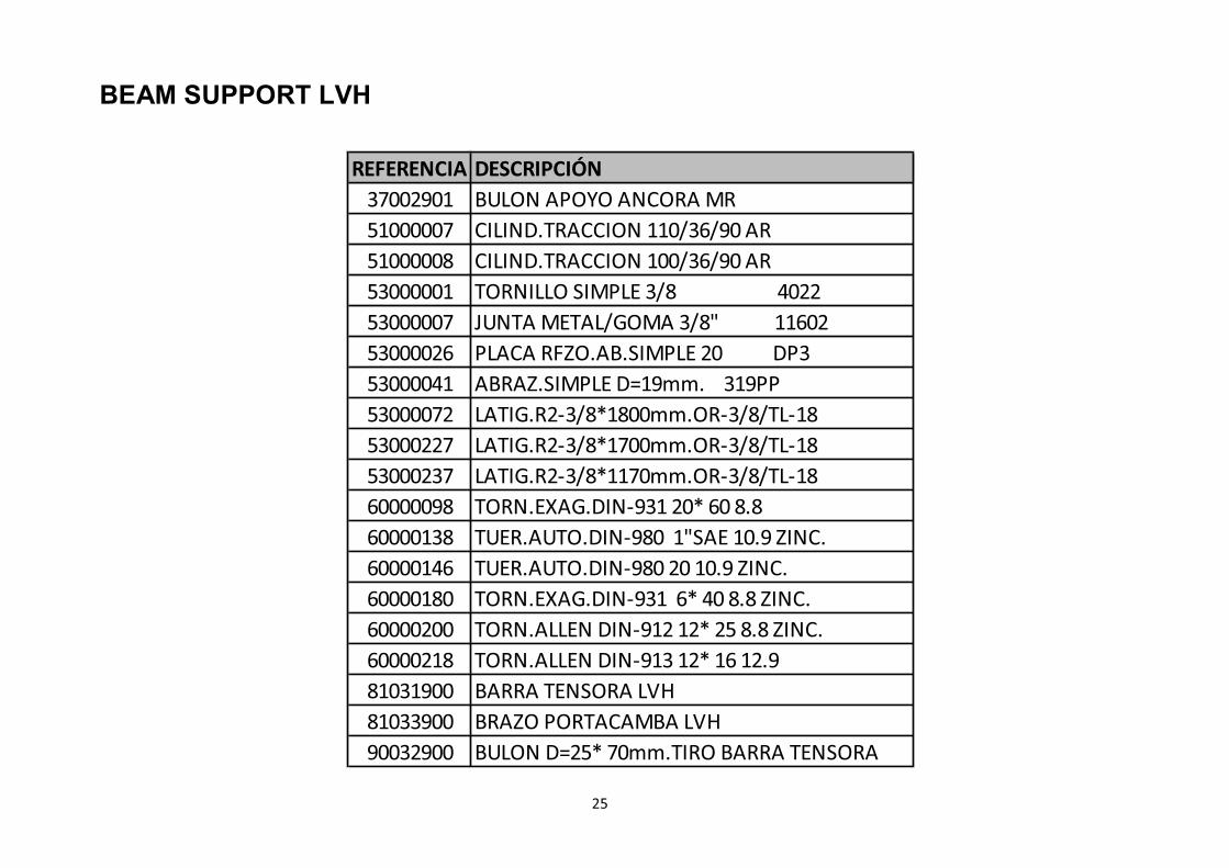
REFERENCIA DESCRIPCIÓN
37002901 BULON APOYO ANCORA MR
51000007 CILIND.TRACCION 110/36/90 AR
51000008 CILIND.TRACCION 100/36/90 AR
53000001 TORNILLO SIMPLE 3/8 4022
53000007 JUNTA METAL/GOMA 3/8" 11602
53000026 PLACA RFZO.AB.SIMPLE 20 DP3
53000041 ABRAZ.SIMPLE D=19mm. 319PP
53000072 LATIG.R2-3/8*1800mm.OR-3/8/TL-18
53000227 LATIG.R2-3/8*1700mm.OR-3/8/TL-18
53000237 LATIG.R2-3/8*1170mm.OR-3/8/TL-18
60000098 TORN.EXAG.DIN-931 20* 60 8.8
60000138 TUER.AUTO.DIN-980 1"SAE 10.9 ZINC.
60000146 TUER.AUTO.DIN-980 20 10.9 ZINC.
60000180 TORN.EXAG.DIN-931 6* 40 8.8 ZINC.
60000200 TORN.ALLEN DIN-912 12* 25 8.8 ZINC.
60000218 TORN.ALLEN DIN-913 12* 16 12.9
81031900 BARRA TENSORA LVH
81033900 BRAZO PORTACAMBA LVH
90032900 BULON D=25* 70mm.TIRO BARRA TENSORA
25
BEAM SUPPORT LVH
26
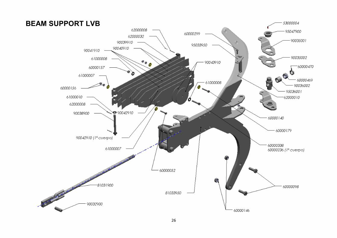
BEAM SUPPORT LVB

REFERENCIA DESCRIPCIÓN REFERENCIA DESCRIPCIÓN
53000004 ENGRASADOR AC° DIN-71412 8*125 62000010 PASADOR ELAST.DIN-1481 8* 40 ZINC.
60000052 TORN.EXAG.DIN-931 10* 55 10.9 ZINC. 62000032 PASADOR ELAST.DIN-1481 3* 30 ZINC.
60000098 TORN.EXAG.DIN-931 20* 60 8.8 81031900 BARRA TENSORA LVH
60000140 TUER.AUTO.DIN-980 10 8.8 ZINC. 81033950 BRAZO PORTACAMBA LVB
60000146 TUER.AUTO.DIN-980 20 10.9 ZINC. 90032900 BULON D=25* 70mm.TIRO BARRA TENSORA
60000156 TUER.EXAG.DIN-934 10 8.8 ZINC. 90035001 BIELA HORQUILLA DCH.
60000157 TUER.EXAG.DIN-934 12 8.8 ZINC. 90035002 BIELA HORQUILLA IZQD.
60000179 TORN.EXAG.DIN-931 10* 60 10.9 ZINC. 90036002 SEP.B.P.40/28* 35mm.
60000236 TORN.EXAG.DIN-933 12* 70 10.9 ZINC. 90038900 PASADOR BALLESTA DACROMET
60000299 TORN.EXAG.DIN-933 10* 30 8.8 90039910 BALLESTA MAESTRA VERDE RAL-6029
60000338 TORN.EXAG.DIN-931 12* 65 10.9 ZINC. 90040910 BALLESTA 1er.RFZO.VERDE RAL-6029
60000469 TUER.EXAG.DIN-934 1"SAE 10.9 ZINC. 90041910 BALLESTA 2° RFZO.VERDE RAL-6029
60000470 TUER.BAJA DIN-936 1"SAE 10.9 ZINC. 90042910 BALLESTA 3er.RFZO.VERDE RAL-6029
61000007 ARAND.DIN-9021 10 ZINC. 90043910 BALLESTA BOTON VERDE RAL-6029
61000008 ARAND.DIN-125 12 ZINC. 95033950 BULON GIRO HORQ.(D/04)
61000010 ARAND.DIN-125 16 ZINC. 95036001 BULON ARTIC.HORQUILLA (D/99)
62000008 PASADOR ELAST.DIN-1481 5* 30 ZINC. 95047900 CASQ.D= 65/49,3/35*25,5mm.GIRO HORQUILLA
27
BEAM SUPPORT LVB

HYDRAULIC SYSTEM
28
REFERENCIA DESCRIPCIÓN REFERENCIA DESCRIPCIÓN
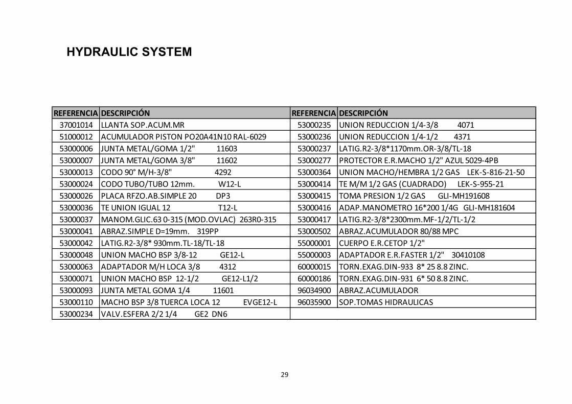
37001014 LLANTA SOP.ACUM.MR 53000235 UNION REDUCCION 1/4-3/8 4071
51000012 ACUMULADOR PISTON PO20A41N10 RAL-6029 53000236 UNION REDUCCION 1/4-1/2 4371
53000006 JUNTA METAL/GOMA 1/2" 11603 53000237 LATIG.R2-3/8*1170mm.OR-3/8/TL-18
53000007 JUNTA METAL/GOMA 3/8" 11602 53000277 PROTECTOR E.R.MACHO 1/2" AZUL 5029-4PB
53000013 CODO 90° M/H-3/8" 4292 53000364 UNION MACHO/HEMBRA 1/2 GAS LEK-S-816-21-50
53000024 CODO TUBO/TUBO 12mm. W12-L 53000414 TE M/M 1/2 GAS (CUADRADO) LEK-S-955-21
53000026 PLACA RFZO.AB.SIMPLE 20 DP3 53000415 TOMA PRESION 1/2 GAS GLI-MH191608
53000036 TE UNION IGUAL 12 T12-L 53000416 ADAP.MANOMETRO 16*200 1/4G GLI-MH181604
53000037 MANOM.GLIC.63 0-315 (MOD.OVLAC) 263R0-315 53000417 LATIG.R2-3/8*2300mm.MF-1/2/TL-1/2
53000041 ABRAZ.SIMPLE D=19mm. 319PP 53000502 ABRAZ.ACUMULADOR 80/88 MPC
53000042 LATIG.R2-3/8* 930mm.TL-18/TL-18 55000001 CUERPO E.R.CETOP 1/2"
53000048 UNION MACHO BSP 3/8-12 GE12-L 55000003 ADAPTADOR E.R.FASTER 1/2" 30410108
53000063 ADAPTADOR M/H LOCA 3/8 4312 60000015 TORN.EXAG.DIN-933 8* 25 8.8 ZINC.
53000071 UNION MACHO BSP 12-1/2 GE12-L1/2 60000186 TORN.EXAG.DIN-931 6* 50 8.8 ZINC.
53000093 JUNTA METAL GOMA 1/4 11601 96034900 ABRAZ.ACUMULADOR
53000110 MACHO BSP 3/8 TUERCA LOCA 12 EVGE12-L 96035900 SOP.TOMAS HIDRAULICAS
53000234 VALV.ESFERA 2/2 1/4 GE2 DN6
29
HYDRAULIC SYSTEM

REFERENCIA DESCRIPCIÓN
15018906 CASQ. D=45/35*8 SEP.APERT.CICRO
51000079 CILIND.APERT. 40/ 80/100 VALV.BLOQ.
53000001 TORNILLO SIMPLE 3/8 4022
53000006 JUNTA METAL/GOMA 1/2" 11603
53000007 JUNTA METAL/GOMA 3/8" 11602
53000179 ABRAZ.DOBLE D=15mm. 215-15PP
53000278 PROTECTOR E.R.MACHO 1/2" AMARILLO 5029-4PY
53000400 PLACA RFZO.AB.DOBLE 15/18
53000456 PLACA SOLDAR AB.DOBLE 15/18 SP2D
53000460 LATIG.MF210-1/4*3550mm.MF-1/2/OR-3/8
55000003 ADAPTADOR E.R.FASTER 1/2" 30410108
60000291 TORN.EXAG.DIN-931/933 8* 40 8.8 ZINC.
60000303 TORN.EXAG.DIN-931 8* 65 8.8 ZINC.
VARYWIDTH SYSTEM
30
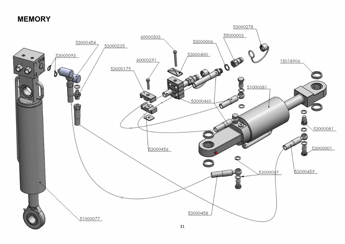
MEMORY
31
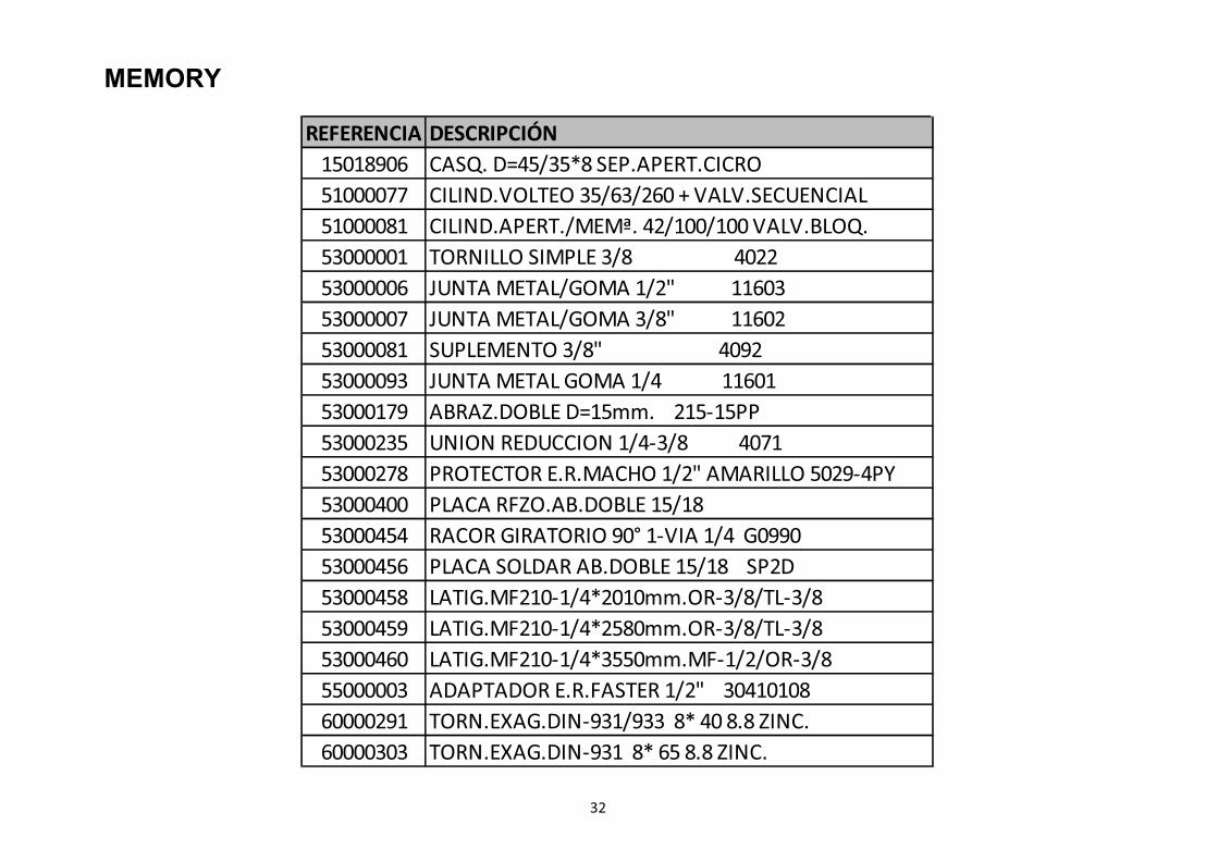
MEMORY
REFERENCIA DESCRIPCIÓN
15018906 CASQ. D=45/35*8 SEP.APERT.CICRO
51000077 CILIND.VOLTEO 35/63/260 + VALV.SECUENCIAL
51000081 CILIND.APERT./MEMª. 42/100/100 VALV.BLOQ.
53000001 TORNILLO SIMPLE 3/8 4022
53000006 JUNTA METAL/GOMA 1/2" 11603
53000007 JUNTA METAL/GOMA 3/8" 11602
53000081 SUPLEMENTO 3/8" 4092
53000093 JUNTA METAL GOMA 1/4 11601
53000179 ABRAZ.DOBLE D=15mm. 215-15PP
53000235 UNION REDUCCION 1/4-3/8 4071
53000278 PROTECTOR E.R.MACHO 1/2" AMARILLO 5029-4PY
53000400 PLACA RFZO.AB.DOBLE 15/18
53000454 RACOR GIRATORIO 90° 1-VIA 1/4 G0990
53000456 PLACA SOLDAR AB.DOBLE 15/18 SP2D
53000458 LATIG.MF210-1/4*2010mm.OR-3/8/TL-3/8
53000459 LATIG.MF210-1/4*2580mm.OR-3/8/TL-3/8
53000460 LATIG.MF210-1/4*3550mm.MF-1/2/OR-3/8
55000003 ADAPTADOR E.R.FASTER 1/2" 30410108
60000291 TORN.EXAG.DIN-931/933 8* 40 8.8 ZINC.
60000303 TORN.EXAG.DIN-931 8* 65 8.8 ZINC.
32
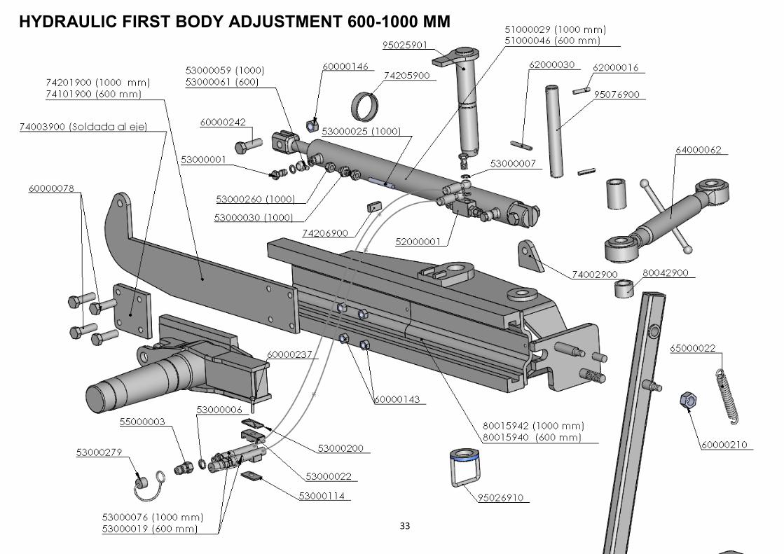
HYDRAULIC FIRST BODY ADJUSTMENT 600-1000 MM
33
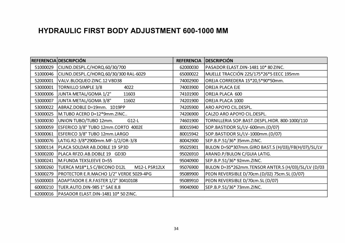
REFERENCIA DESCRIPCIÓN REFERENCIA DESCRIPCIÓN
51000029 CILIND.DESPL.C/HORQ.60/30/700 62000030 PASADOR ELAST.DIN-1481 10* 80 ZINC.
51000046 CILIND.DESPL.C/HORQ.60/30/300 RAL-6029 65000022 MUELLE TRACCIÓN 225/175*26*5 EECC 195mm
52000001 VALV.BLOQUEO ZINC.12 VBD38 74002900 OREJA CORREDERA 15*20,5*90*50mm.
53000001 TORNILLO SIMPLE 3/8 4022 74003900 OREJA PLACA EJE
53000006 JUNTA METAL/GOMA 1/2" 11603 74101900 OREJA PLACA 600
53000007 JUNTA METAL/GOMA 3/8" 11602 74201900 OREJA PLACA 1000
53000022 ABRAZ.DOBLE D=19mm. 1D19PP 74205900 ARO APOYO CIL.DESPL.
53000025 M.TUBO ACERO D=12*9mm.ZINC.. 74206900 CALZO ARO APOYO CIL.DESPL.
53000030 UNION TUBO/TUBO 12mm. G12-L 74601900 TORNILLERIA SOP.BAST.DESPL.HIDR. 800-1000/110
53000059 ESFERICO 3/8" TUBO 12mm.CORTO 4002E 80015940 SOP.BASTIDOR SL/LV-600mm.(D/07)
53000061 ESFERICO 3/8" TUBO 12mm.LARGO 80015942 SOP.BASTIDOR SL/LV-1000mm.(D/07)
53000076 LATIG.R2-3/8*2900mm.MF-1/2/OR-3/8 80042900 SEP.B.P.51/36* 35mm.ZINC.
53000114 PLACA SOLDAR AB.DOBLE 19 SP3D 95025901 BULON D=50*307mm.GIRO BAST.S (H/03)/FB(H/07)/SL/LV
53000200 PLACA RFZO.AB.DOBLE 19 GD3D 95026910 ARAND.P/BULON C/GUIA LATIG.
53000241 M.FUNDA TEXSLEEVE D=55 95040900 SEP.B.P.51/36* 92mm.ZINC.
53000260 TUERCA M18*1,5 C/BICONO D12L M12-L PSR12LX 95076900 BULON D=35*262mm.TENSOR ANTER.S (H/03)/SL/LV (D/03
53000279 PROTECTOR E.R.MACHO 1/2" VERDE 5029-4PG 95089900 PEON REVERSIBLE D/70cm.(D/02) 75cm.SL (D/07)
55000003 ADAPTADOR E.R.FASTER 1/2" 30410108 95089910 PEON REVERSIBLE D/70cm.SL (D/07)
60000210 TUER.AUTO.DIN-985 1" SAE 8.8 99040900 SEP.B.P.51/36* 73mm.ZINC.
62000016 PASADOR ELAST.DIN-1481 10* 50 ZINC.
34
HYDRAULIC FIRST BODY ADJUSTMENT 600-1000 MM
BODIES V-97 / V-31 / V-90 / V-74
35
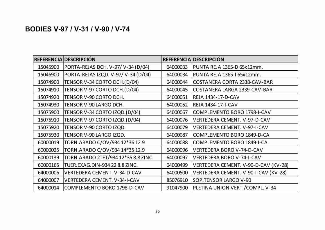
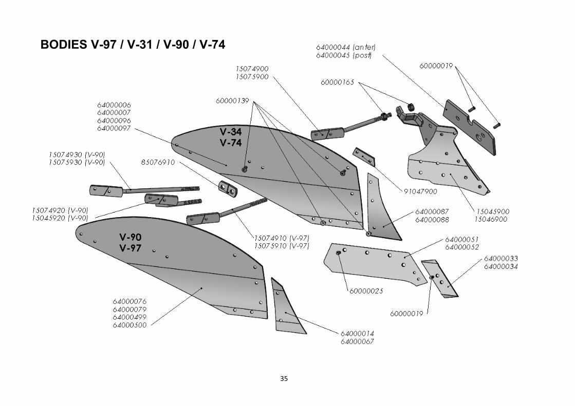
BODIES V-97 / V-31 / V-90 / V-74
REFERENCIA DESCRIPCIÓN REFERENCIA DESCRIPCIÓN
15045900 PORTA-REJAS DCH. V-97/ V-34 (D/04) 64000033 PUNTA REJA 1365-D 65x12mm.
15046900 PORTA-REJAS IZQD. V-97/ V-34 (D/04) 64000034 PUNTA REJA 1365-I 65x12mm.
15074900 TENSOR V-34 CORTO DCH.(D/04) 64000044 COSTANERA CORTA 2338-CAV-BAR
15074910 TENSOR V-97 CORTO DCH.(D/04) 64000045 COSTANERA LARGA 2339-CAV-BAR
15074920 TENSOR V-90 CORTO DCH. 64000051 REJA 1434-17-D-CAV
15074930 TENSOR V-90 LARGO DCH. 64000052 REJA 1434-17-I-CAV
15075900 TENSOR V-34 CORTO IZQD.(D/04) 64000067 COMPLEMENTO BORO 1798-I-CAV
15075910 TENSOR V-97 CORTO IZQD.(D/04) 64000076 VERTEDERA CEMENT. V-97-D-CAV
15075920 TENSOR V-90 CORTO IZQD. 64000079 VERTEDERA CEMENT. V-97-I-CAV
15075930 TENSOR V-90 LARGO IZQD. 64000087 COMPLEMENTO BORO 1849-D-CA
60000019 TORN.ARADO C/OV/934 12*36 12.9 64000088 COMPLEMENTO BORO 1849-I-CA
60000025 TORN.ARADO C/OV/934 14*35 12.9 64000096 VERTEDERA BORO V-74-D-CAV
60000139 TORN.ARADO 2TET/934 12*35 8.8 ZINC. 64000097 VERTEDERA BORO V-74-I-CAV
60000165 TUER.EXAG.DIN-934 22 8.8 ZINC. 64000499 VERTEDERA CEMENT. V-90-D-CAV (KV-28)
64000006 VERTEDERA CEMENT. V-34-D-CAV 64000500 VERTEDERA CEMENT. V-90-I-CAV (KV-28)
64000007 VERTEDERA CEMENT. V-34-I-CAV 85076910 SOP.TENSOR LARGO V-90
64000014 COMPLEMENTO BORO 1798-D-CAV 91047900 PLETINA UNION VERT./COMPL. V-34
36
BODIES V-40
37
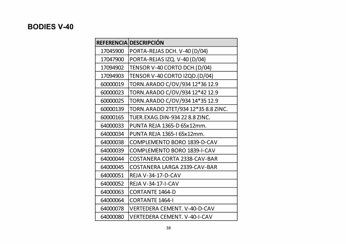
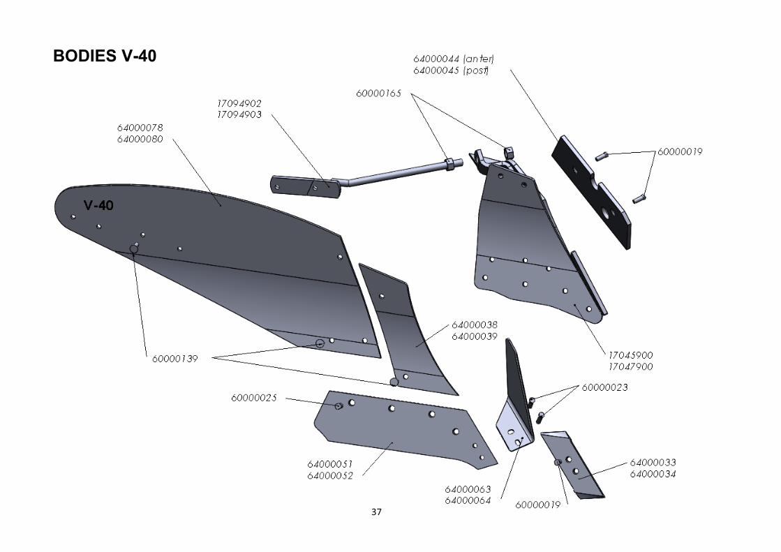
BODIES V-40
REFERENCIA DESCRIPCIÓN
17045900 PORTA-REJAS DCH. V-40 (D/04)
17047900 PORTA-REJAS IZQ. V-40 (D/04)
17094902 TENSOR V-40 CORTO DCH.(D/04)
17094903 TENSOR V-40 CORTO IZQD.(D/04)
60000019 TORN.ARADO C/OV/934 12*36 12.9
60000023 TORN.ARADO C/OV/934 12*42 12.9
60000025 TORN.ARADO C/OV/934 14*35 12.9
60000139 TORN.ARADO 2TET/934 12*35 8.8 ZINC.
60000165 TUER.EXAG.DIN-934 22 8.8 ZINC.
64000033 PUNTA REJA 1365-D 65x12mm.
64000034 PUNTA REJA 1365-I 65x12mm.
64000038 COMPLEMENTO BORO 1839-D-CAV
64000039 COMPLEMENTO BORO 1839-I-CAV
64000044 COSTANERA CORTA 2338-CAV-BAR
64000045 COSTANERA LARGA 2339-CAV-BAR
64000051 REJA V-34-17-D-CAV
64000052 REJA V-34-17-I-CAV
64000063 CORTANTE 1464-D
64000064 CORTANTE 1464-I
64000078 VERTEDERA CEMENT. V-40-D-CAV
64000080 VERTEDERA CEMENT. V-40-I-CAV
38
BODIES LOV
39
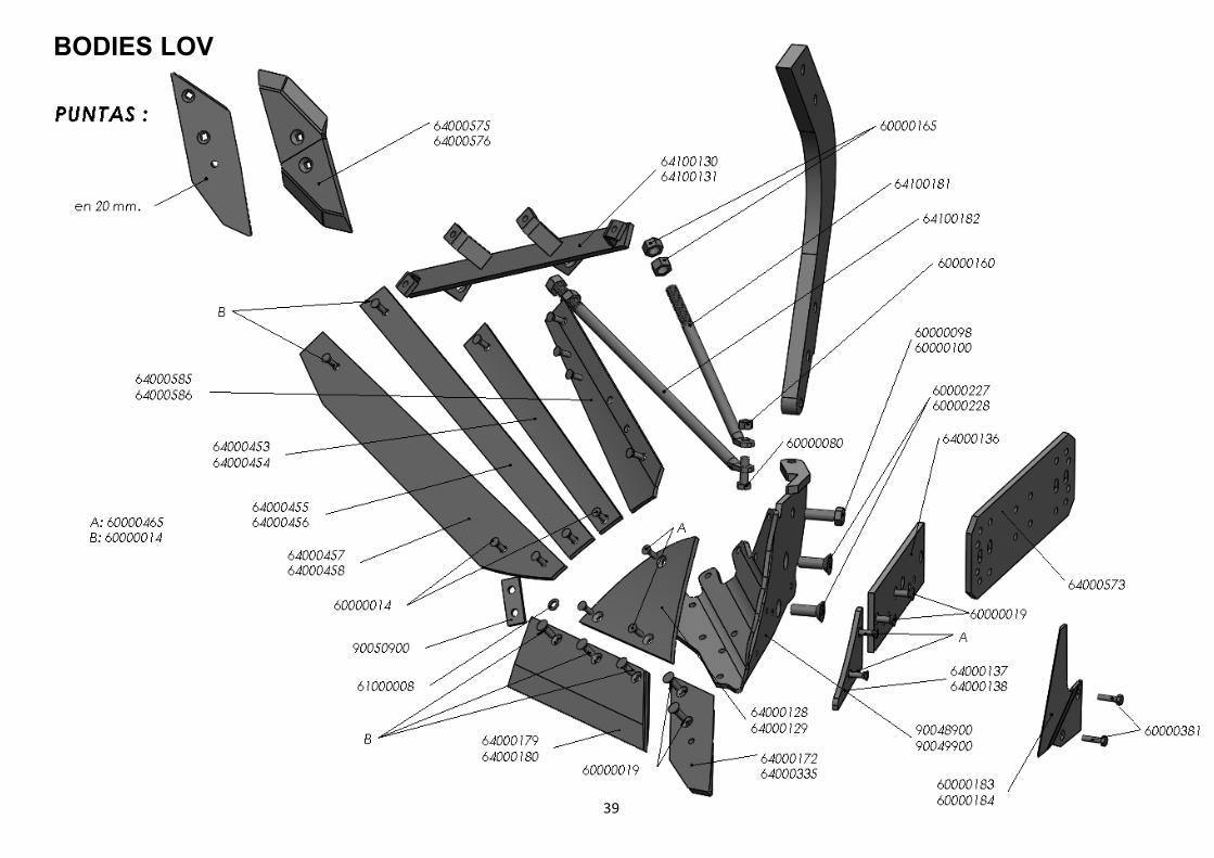
BODIES LOV
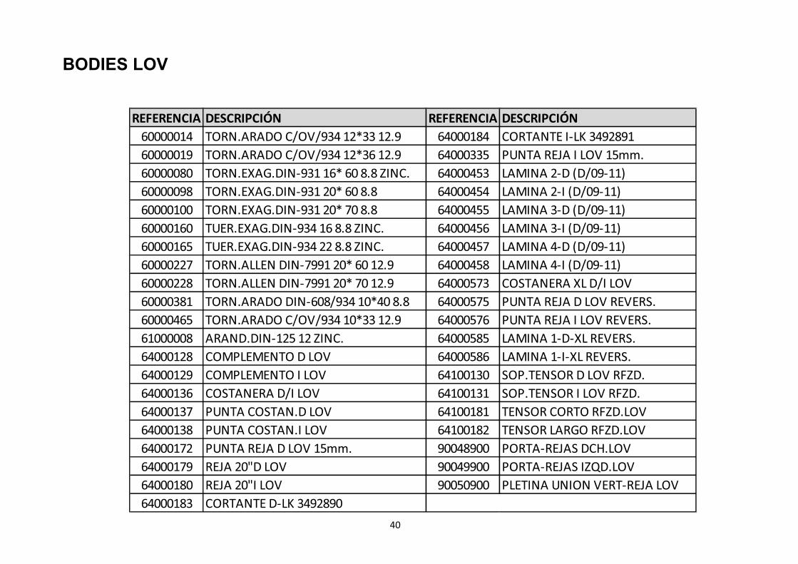
REFERENCIA DESCRIPCIÓN REFERENCIA DESCRIPCIÓN
60000014 TORN.ARADO C/OV/934 12*33 12.9 64000184 CORTANTE I-LK 3492891
60000019 TORN.ARADO C/OV/934 12*36 12.9 64000335 PUNTA REJA I LOV 15mm.
60000080 TORN.EXAG.DIN-931 16* 60 8.8 ZINC. 64000453 LAMINA 2-D (D/09-11)
60000098 TORN.EXAG.DIN-931 20* 60 8.8 64000454 LAMINA 2-I (D/09-11)
60000100 TORN.EXAG.DIN-931 20* 70 8.8 64000455 LAMINA 3-D (D/09-11)
60000160 TUER.EXAG.DIN-934 16 8.8 ZINC. 64000456 LAMINA 3-I (D/09-11)
60000165 TUER.EXAG.DIN-934 22 8.8 ZINC. 64000457 LAMINA 4-D (D/09-11)
60000227 TORN.ALLEN DIN-7991 20* 60 12.9 64000458 LAMINA 4-I (D/09-11)
60000228 TORN.ALLEN DIN-7991 20* 70 12.9 64000573 COSTANERA XL D/I LOV
60000381 TORN.ARADO DIN-608/934 10*40 8.8 64000575 PUNTA REJA D LOV REVERS.
60000465 TORN.ARADO C/OV/934 10*33 12.9 64000576 PUNTA REJA I LOV REVERS.
61000008 ARAND.DIN-125 12 ZINC. 64000585 LAMINA 1-D-XL REVERS.
64000128 COMPLEMENTO D LOV 64000586 LAMINA 1-I-XL REVERS.
64000129 COMPLEMENTO I LOV 64100130 SOP.TENSOR D LOV RFZD.
64000136 COSTANERA D/I LOV 64100131 SOP.TENSOR I LOV RFZD.
64000137 PUNTA COSTAN.D LOV 64100181 TENSOR CORTO RFZD.LOV
64000138 PUNTA COSTAN.I LOV 64100182 TENSOR LARGO RFZD.LOV
64000172 PUNTA REJA D LOV 15mm. 90048900 PORTA-REJAS DCH.LOV
64000179 REJA 20"D LOV 90049900 PORTA-REJAS IZQD.LOV
64000180 REJA 20"I LOV 90050900 PLETINA UNION VERT-REJA LOV
64000183 CORTANTE D-LK 3492890
40
BODIES V-PLÁSTICO
41

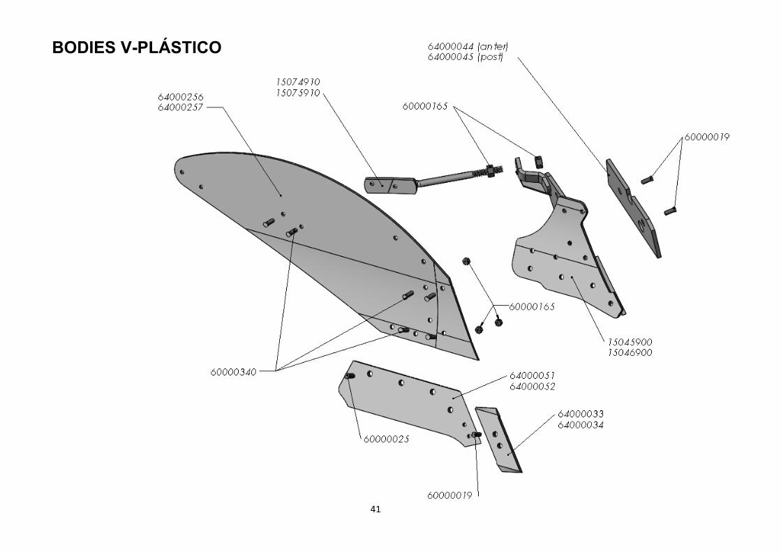
REFERENCIA DESCRIPCIÓN
64000044 COSTANERA CORTA 2338-CAV-BAR
64000045 COSTANERA LARGA 2339-CAV-BAR
60000019 TORN.ARADO C/OV/934 12*36 12.9
60000165 TUER.EXAG.DIN-934 22 8.8 ZINC.
15045900 PORTA-REJAS DCH.1797/1834 (D/04)
15074910 TENSOR 1797 CORTO DCH.(D/04)
64000256 VERTEDERA PLASTIC.D A73286M (1797)
60000340 TORN.ARADO DIN-603 12*40 8.8 ZINC.
60000025 TORN.ARADO C/OV/934 14*35 12.9
60000019 TORN.ARADO C/OV/934 12*36 12.9
64000033 PUNTA REJA 1365-D 65x12mm.
64000051 REJA 1434-17-D-CAV
15046900 PORTA-REJAS IZQD.1797/1834 (D/04)
64000257 VERTEDERA PLASTIC.I A73287M (1797)
64000052 REJA 1434-17-I-CAV
64000034 PUNTA REJA 1365-I 65x12mm.
15075910 TENSOR 1797 CORTO IZQD.(D/04)
BODIES V-PLÁSTICO
42
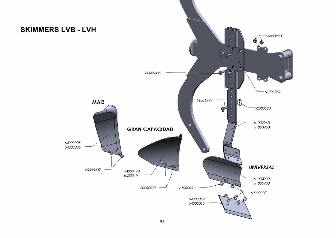
SKIMMERS LVB - LVH
43
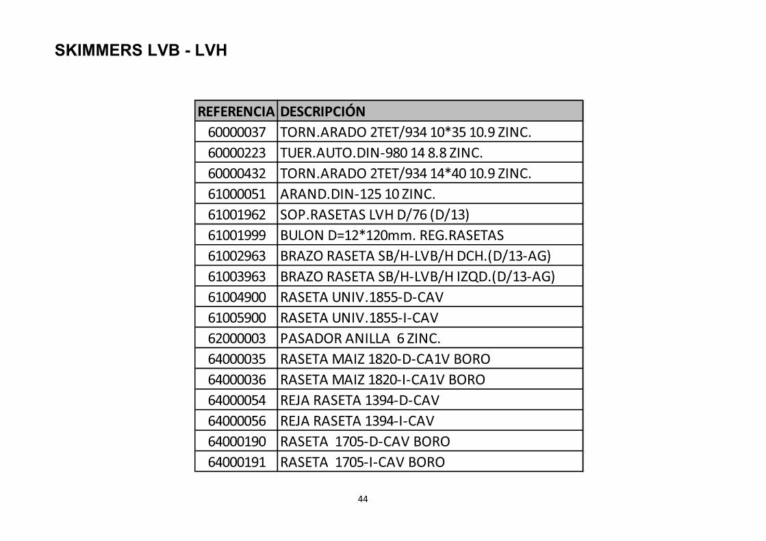
SKIMMERS LVB - LVH
44
REFERENCIA DESCRIPCIÓN
60000037 TORN.ARADO 2TET/934 10*35 10.9 ZINC.
60000223 TUER.AUTO.DIN-980 14 8.8 ZINC.
60000432 TORN.ARADO 2TET/934 14*40 10.9 ZINC.
61000051 ARAND.DIN-125 10 ZINC.
61001962 SOP.RASETAS LVH D/76 (D/13)
61001999 BULON D=12*120mm. REG.RASETAS
61002963 BRAZO RASETA SB/H-LVB/H DCH.(D/13-AG)
61003963 BRAZO RASETA SB/H-LVB/H IZQD.(D/13-AG)
61004900 RASETA UNIV.1855-D-CAV
61005900 RASETA UNIV.1855-I-CAV
62000003 PASADOR ANILLA 6 ZINC.
64000035 RASETA MAIZ 1820-D-CA1V BORO
64000036 RASETA MAIZ 1820-I-CA1V BORO
64000054 REJA RASETA 1394-D-CAV
64000056 REJA RASETA 1394-I-CAV
64000190 RASETA 1705-D-CAV BORO
64000191 RASETA 1705-I-CAV BORO
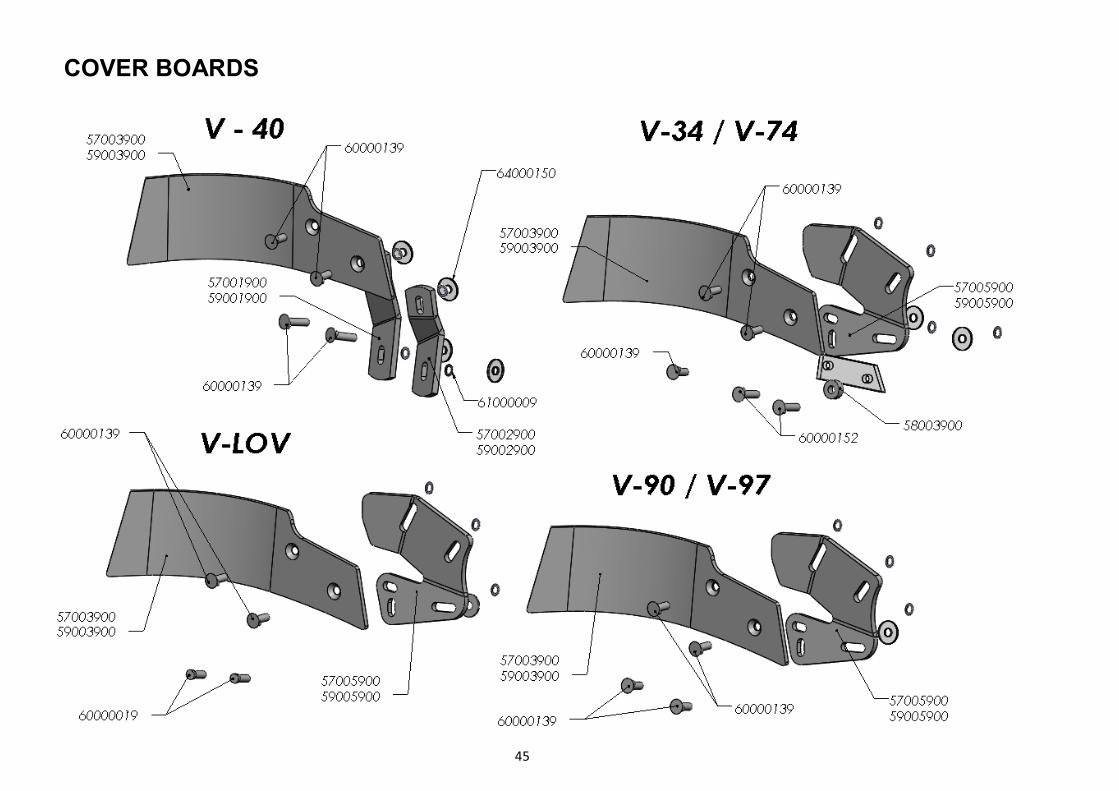
COVER BOARDS
45

REFERENCIA DESCRIPCIÓN
57001900 SOP.POST.DCH.C.R.1840/V-LK
57002900 SOP.ANTER.DCH.C.R.1840/POST.DCH.1701
57003900 DEFLECTOR BORO 1856-D-CAV
57005900 SOPORTE C.R. DCH.(1797-1834-VLAM)
58003900 CASQ.D= 30/13*12mm.SEP.SOP.C.R.1834 ZINC.
59001900 SOP.POST.IZQD.C.R.1840/V-LK
59002900 SOP.ANTER.IZQD.C.R.1840/POST.IZQD.1701
59003900 DEFLECTOR BORO 1856-I-CAV
59005900 SOPORTE C.R. IZQ.(1797-1834-VLAM)
60000019 TORN.ARADO C/OV/934 12*36 12.9
60000139 TORN.ARADO 2TET/934 12*35 8.8 ZINC.
60000152 TORN.ARADO 2TET/934 12*45 8.8 ZINC.
61000009 ARAND.DIN-9021 12 ZINC.
64000150 ARAND.GOMA ADHESIVA M-12
46
COVER BOARDS
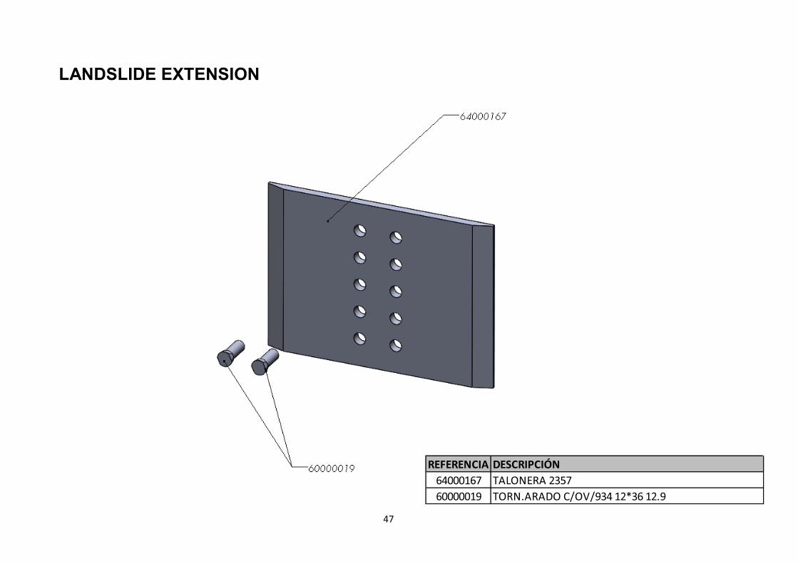
LANDSLIDE EXTENSION
REFERENCIA DESCRIPCIÓN
64000167 TALONERA 2357
60000019 TORN.ARADO C/OV/934 12*36 12.9
47
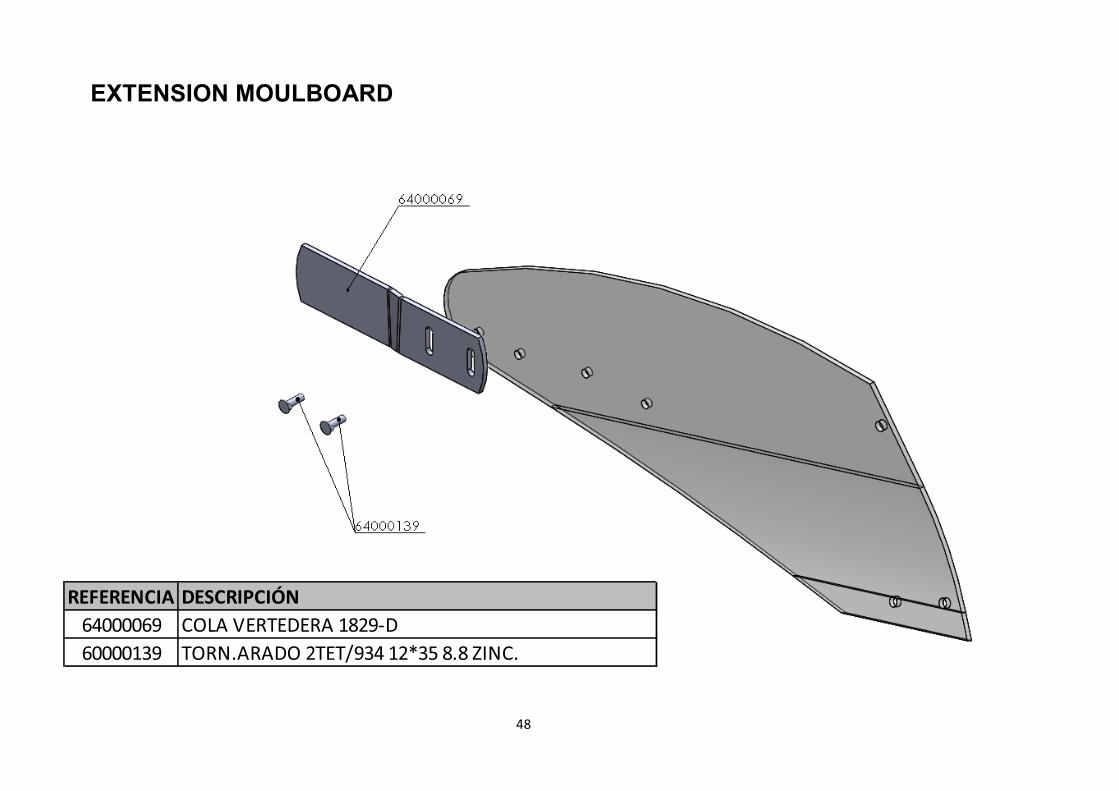
EXTENSION MOULBOARD
REFERENCIA DESCRIPCIÓN
64000069 COLA VERTEDERA 1829-D
60000139 TORN.ARADO 2TET/934 12*35 8.8 ZINC.
48

EXPANDER GROOVE
REFERENCIA DESCRIPCIÓN
64000094 AMPLIADOR SURCO 1459-D
64000095 AMPLIADOR SURCO 1459-I
64000167 TALONERA 2357
60000025 TORN.ARADO C/OV/934 14*35 12.9
49
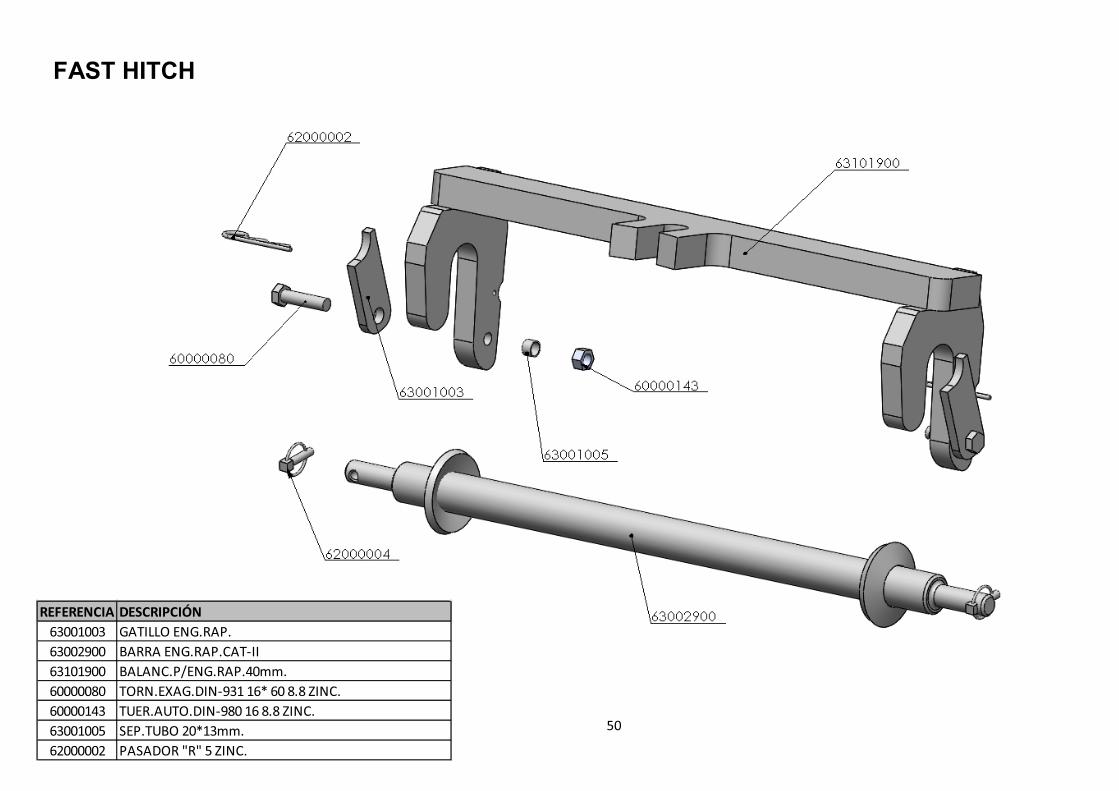
FAST HITCH
REFERENCIA DESCRIPCIÓN
63001003 GATILLO ENG.RAP.
63002900 BARRA ENG.RAP.CAT-II
63101900 BALANC.P/ENG.RAP.40mm.
60000080 TORN.EXAG.DIN-931 16* 60 8.8 ZINC.
60000143 TUER.AUTO.DIN-980 16 8.8 ZINC.
63001005 SEP.TUBO 20*13mm.
62000002 PASADOR "R" 5 ZINC.
50

51
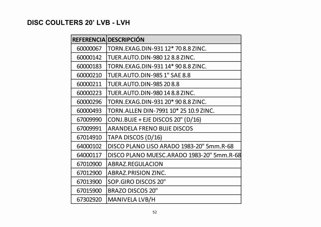
DISC COULTERS 20’ LVB - LVH
52
DISC COULTERS 20’ LVB - LVH
REFERENCIA DESCRIPCIÓN
60000067 TORN.EXAG.DIN-931 12* 70 8.8 ZINC.
60000142 TUER.AUTO.DIN-980 12 8.8 ZINC.
60000183 TORN.EXAG.DIN-931 14* 90 8.8 ZINC.
60000210 TUER.AUTO.DIN-985 1" SAE 8.8
60000211 TUER.AUTO.DIN-985 20 8.8
60000223 TUER.AUTO.DIN-980 14 8.8 ZINC.
60000296 TORN.EXAG.DIN-931 20* 90 8.8 ZINC.
60000493 TORN.ALLEN DIN-7991 10* 25 10.9 ZINC.
67009990 CONJ.BUJE + EJE DISCOS 20" (D/16)
67009991 ARANDELA FRENO BUJE DISCOS
67014910 TAPA DISCOS (D/16)
64000102 DISCO PLANO LISO ARADO 1983-20" 5mm.R-68
64000117 DISCO PLANO MUESC.ARADO 1983-20" 5mm.R-68
67010900 ABRAZ.REGULACION
67012900 ABRAZ.PRISION ZINC.
67013900 SOP.GIRO DISCOS 20"
67015900 BRAZO DISCOS 20"
67302920 MANIVELA LVB/H

DISC COULTERS NON STOP 20’ LVB - LVH
53

54
DISC COULTERS NON STOP 20’ LVB - LVH
REFERENCIA DESCRIPCIÓN REFERENCIA DESCRIPCIÓN
60000067 TORN.EXAG.DIN-931 12* 70 8.8 ZINC. 64000117 DISCO PLANO MUESC.ARADO 1983-20" 5mm.R-68
60000142 TUER.AUTO.DIN-980 12 8.8 ZINC. 65000014 MUELLE COMPR.CILIN.275*57*12 LUZ-5
60000146 TUER.AUTO.DIN-980 20 10.9 ZINC. 67009990 CONJ.BUJE + EJE DISCOS 20" (D/16)
60000163 TUER.EXAG.DIN-934 20 8.8 67009991 ARANDELA FRENO BUJE DISCOS
60000183 TORN.EXAG.DIN-931 14* 90 8.8 ZINC. 67010900 ABRAZ.REGULACION
60000210 TUER.AUTO.DIN-985 1" SAE 8.8 67012900 ABRAZ.PRISION ZINC.
60000211 TUER.AUTO.DIN-985 20 8.8 67014910 TAPA DISCOS (D/16)
60000223 TUER.AUTO.DIN-980 14 8.8 ZINC. 67103900 GIRO DISCOS NON-STOP
60000274 TORN.EXAG.DIN-931 20* 70 8.8 ZINC. 67104900 PLACA SOP.GIRO DISCOS NON-STOP
60000302 TORN.EXAG.DIN-931 12* 55 8.8 67105900 BRAZO DISCOS NON-STOP
60000493 TORN.ALLEN DIN-7991 10* 25 10.9 ZINC. 67107900 CORREDERA MUELLE DISCOS NON-STOP
64000001 DISCO PLANO LISO ARADO 1983-18" 5mm.R-68 67111900 CASQ.D= 30/12,5*21mm.SEP.SOP.DISCOS NON-STOP
64000083 DISCO PLANO MUESC.ARADO 1983-18" 5mm.R-68 67302920 MANIVELA LVB/H
64000102 DISCO PLANO LISO ARADO 1983-20" 5mm.R-68 70005900 ARAND.RFZO.D= 58*21 E-10mm.
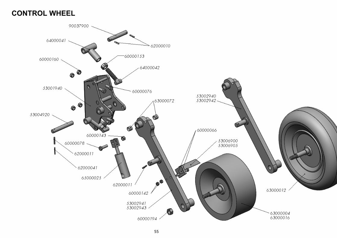
CONTROL WHEEL
55
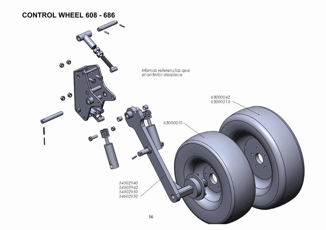
CONTROL WHEEL 608 - 686
56
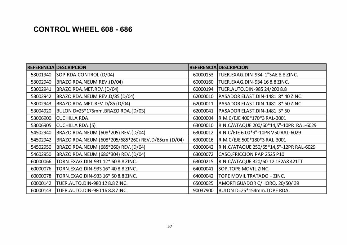
REFERENCIA DESCRIPCIÓN REFERENCIA DESCRIPCIÓN
53001940 SOP.RDA.CONTROL (D/04) 60000153 TUER.EXAG.DIN-934 1"SAE 8.8 ZINC.
53002940 BRAZO RDA.NEUM.REV.(D/04) 60000160 TUER.EXAG.DIN-934 16 8.8 ZINC.
53002941 BRAZO RDA.MET.REV.(D/04) 60000194 TUER.AUTO.DIN-985 24/200 8.8
53002942 BRAZO RDA.NEUM.REV.D/85 (D/04) 62000010 PASADOR ELAST.DIN-1481 8* 40 ZINC.
53002943 BRAZO RDA.MET.REV.D/85 (D/04) 62000011 PASADOR ELAST.DIN-1481 8* 50 ZINC.
53004920 BULON D=25*175mm.BRAZO RDA.(D/03) 62000041 PASADOR ELAST.DIN-1481 5* 50
53006900 CUCHILLA RDA. 63000004 R.M.C/EJE 400*170*3 RAL-3001
53006905 CUCHILLA RDA.(5) 63000010 R.N.C/ATAQUE 200/60*14,5"-10PR RAL-6029
54502940 BRAZO RDA.NEUM.(608*205) REV.(D/04) 63000012 R.N.C/EJE 6.00*9"-10PR V50 RAL-6029
54502942 BRAZO RDA.NEUM.(608*205/685*260) REV.D/85cm.(D/04) 63000016 R.M.C/EJE 500*180*3 RAL-3001
54502950 BRAZO RDA.NEUM.(685*260) REV.(D/04) 63000042 R.N.C/ATAQUE 250/65*14,5"-12PR RAL-6029
54602950 BRAZO RDA.NEUM.(686*304) REV.(D/04) 63000072 CASQ.FRICCION PAP 2525 P10
60000066 TORN.EXAG.DIN-931 12* 60 8.8 ZINC. 63000215 R.N.C/ATAQUE 320/60-12 132A8 421TT
60000076 TORN.EXAG.DIN-933 16* 40 8.8 ZINC. 64000041 SOP.TOPE MOVIL ZINC.
60000078 TORN.EXAG.DIN-933 16* 50 8.8 ZINC. 64000042 TOPE MOVIL TRATADO + ZINC.
60000142 TUER.AUTO.DIN-980 12 8.8 ZINC. 65000025 AMORTIGUADOR C/HORQ. 20/50/ 39
60000143 TUER.AUTO.DIN-980 16 8.8 ZINC. 90037900 BULON D=25*154mm.TOPE RDA.
57
CONTROL WHEEL 608 - 686
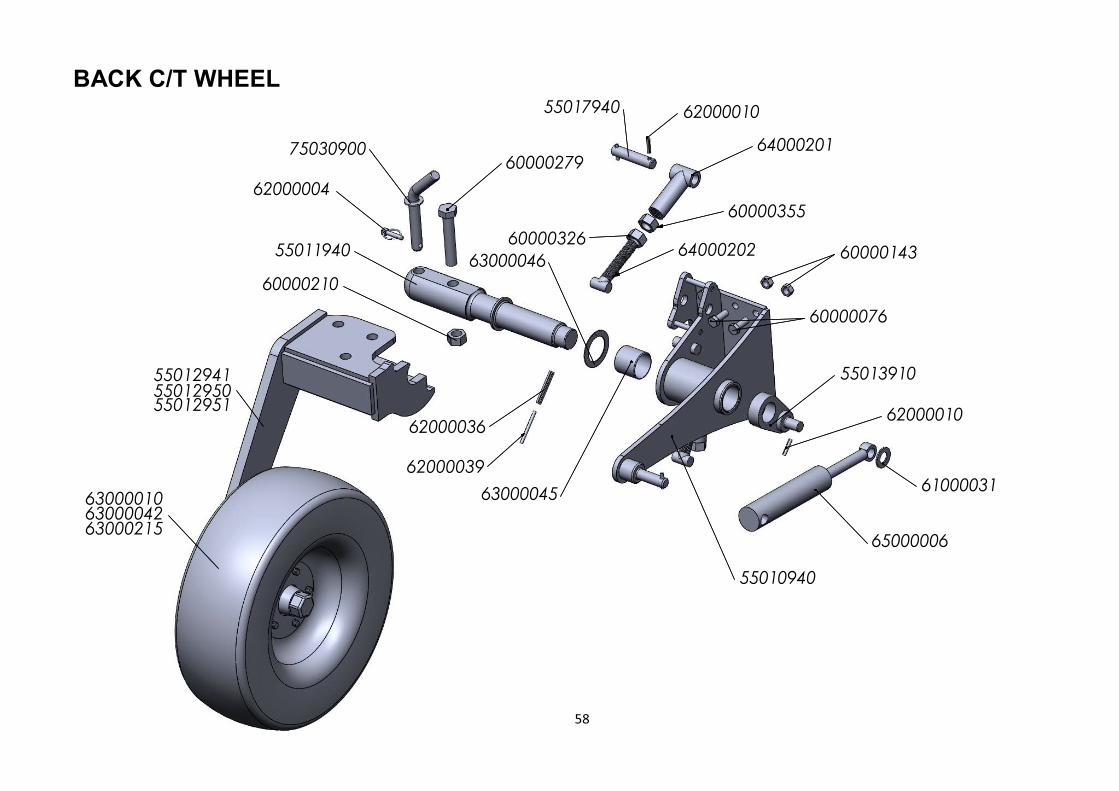
BACK C/T WHEEL
58
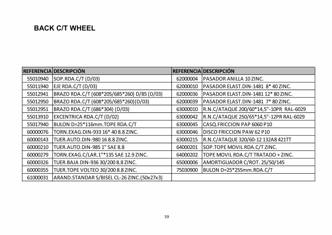
REFERENCIA DESCRIPCIÓN REFERENCIA DESCRIPCIÓN
55010940 SOP.RDA.C/T (D/03) 62000004 PASADOR ANILLA 10 ZINC.
55011940 EJE RDA.C/T (D/03) 62000010 PASADOR ELAST.DIN-1481 8* 40 ZINC.
55012941 BRAZO RDA.C/T (608*205/685*260) D/85 (D/03) 62000036 PASADOR ELAST.DIN-1481 12* 80 ZINC.
55012950 BRAZO RDA.C/T (608*205/685*260)(D/03) 62000039 PASADOR ELAST.DIN-1481 7* 80 ZINC.
55012951 BRAZO RDA.C/T (686*304) (D/03) 63000010 R.N.C/ATAQUE 200/60*14,5"-10PR RAL-6029
55013910 EXCENTRICA RDA.C/T (D/02) 63000042 R.N.C/ATAQUE 250/65*14,5"-12PR RAL-6029
55017940 BULON D=25*116mm.TOPE RDA.C/T 63000045 CASQ.FRICCION PAP 6060 P10
60000076 TORN.EXAG.DIN-933 16* 40 8.8 ZINC. 63000046 DISCO FRICCION PAW 62 P10
60000143 TUER.AUTO.DIN-980 16 8.8 ZINC. 63000215 R.N.C/ATAQUE 320/60-12 132A8 421TT
60000210 TUER.AUTO.DIN-985 1" SAE 8.8 64000201 SOP.TOPE MOVIL RDA.C/T ZINC.
60000279 TORN.EXAG.C/LAR.1"*135 SAE 12.9 ZINC. 64000202 TOPE MOVIL RDA.C/T TRATADO + ZINC.
60000326 TUER.BAJA DIN-936 30/200 8.8 ZINC. 65000006 AMORTIGUADOR C/ROT. 25/50/145
60000355 TUER.TOPE VOLTEO 30/200 8.8 ZINC. 75030900 BULON D=25*255mm.RDA.C/T
61000031 ARAND.STANDAR S/BISEL CL-26 ZINC.(50x27x3)
59
BACK C/T WHEEL
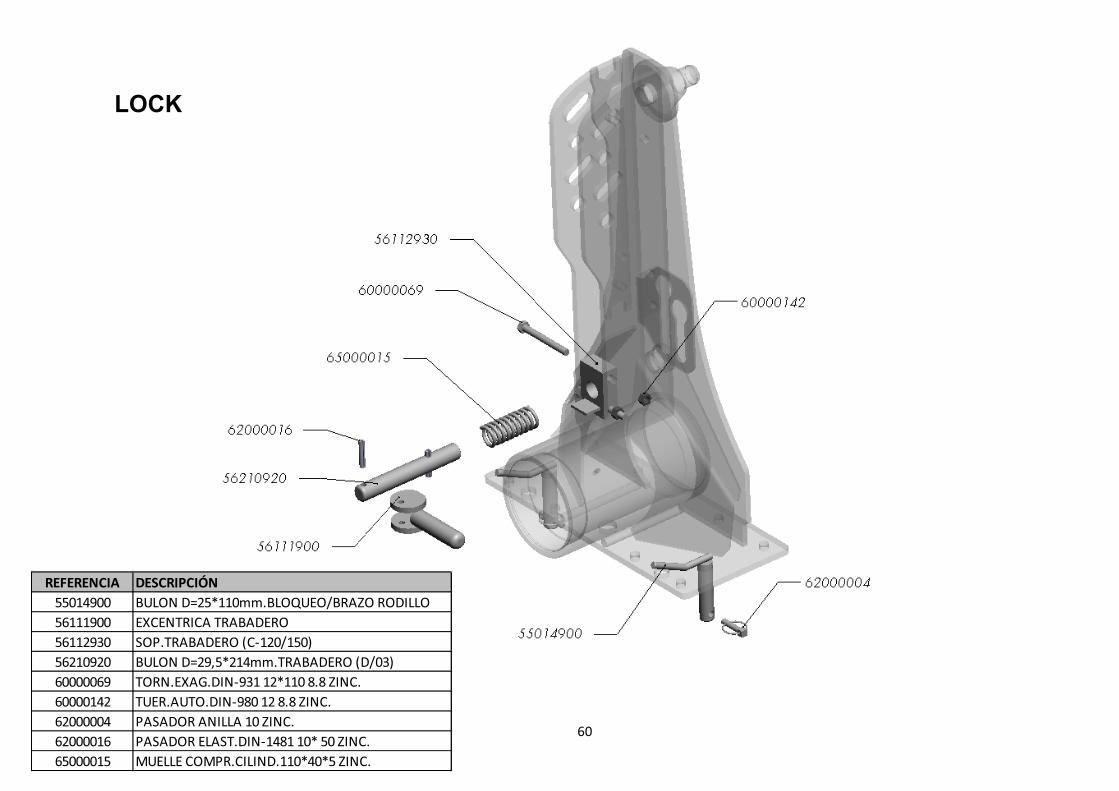
LOCK
60
REFERENCIA DESCRIPCIÓN
55014900 BULON D=25*110mm.BLOQUEO/BRAZO RODILLO
56111900 EXCENTRICA TRABADERO
56112930 SOP.TRABADERO (C-120/150)
56210920 BULON D=29,5*214mm.TRABADERO (D/03)
60000069 TORN.EXAG.DIN-931 12*110 8.8 ZINC.
60000142 TUER.AUTO.DIN-980 12 8.8 ZINC.
62000004 PASADOR ANILLA 10 ZINC.
62000016 PASADOR ELAST.DIN-1481 10* 50 ZINC.
65000015 MUELLE COMPR.CILIND.110*40*5 ZINC.
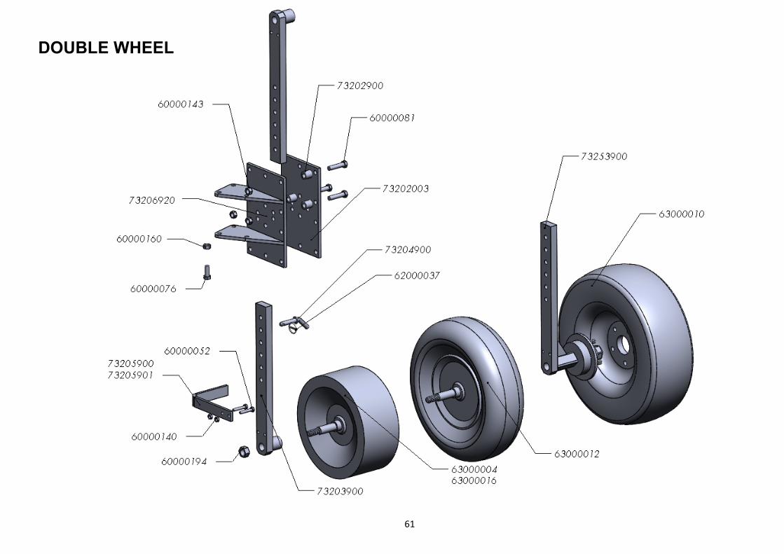
DOUBLE WHEEL
61

62
REFERENCIA DESCRIPCIÓN
60000052 TORN.EXAG.DIN-931 10* 55 10.9 ZINC.
60000076 TORN.EXAG.DIN-933 16* 40 8.8 ZINC.
60000081 TORN.EXAG.DIN-931 16* 70 8.8 ZINC.
60000140 TUER.AUTO.DIN-980 10 8.8 ZINC.
60000143 TUER.AUTO.DIN-980 16 8.8 ZINC.
60000160 TUER.EXAG.DIN-934 16 8.8 ZINC.
60000194 TUER.AUTO.DIN-985 24/200 8.8
62000037 PASADOR ANILLA 4,5 ZINC.
63000004 R.M.C/EJE 400*170*3 RAL-3001
63000010 R.N.C/ATAQUE 200/60*14,5"-10PR RAL-6029
63000012 R.N.C/EJE 6.00*9"-10PR V50 RAL-6029
63000016 R.M.C/EJE 500*180*3 RAL-3001
73202003 PLACA LAT.RDA.DOBLE S (D/03)
73202900 CASQ.D= 30/16,5*31,5mm.SEP.SOP.RDA.DOBLE
73203900 BRAZO RDA.DOBLE MET./NEUM.
73204900 BULON D=16*150mm.REG.RDA.DOBLE
73205900 CUCHILLA RDA.MET.DOBLE
73205901 CUCHILLA RDA.DOBLE (5)
73206920 SOP.RDA.DOBLE LV (D/04)
73253900 BRAZO RDA.DOBLE NEUM.(608*205)
DOUBLE WHEEL
63