results of the magnetometer navigation (magnav) … · results of the magnetometer navigation...
TRANSCRIPT
RESULTS OF THE MAGNETOMETER NAVIGATION
(MAGNAV) INFLIGHT EXPERIMENT
Julie K. Thienel' and Richard R. Harmant NASA Goddard Space Flight Center, Flight Dynamics Analysis Branch
Greenbelt, Maryland, 2 l O 4 USA
Itzhack Y. Bar-Itzhackt Technion-Israel Institute of Technology, Haafa, Israel 32000
Mike Lambertsons Computer Sciences Corporation, 7700 Hubble Drive, Lanham, Maryland, 20706, USA
The Magnetometer Navigation (MAGNAV) algorithm is currently running as a flight experiment as part of the Wide Field Infrared Explorer (WIRE) Post-Science Engineering Testbed. Initialization of MAGNAV occurred on September 4, 2003. MAGNAV is designed to autonomously estimate the spacecraft orbit, attitude, and rate using magnetometer and sun sensor data. Since the Earth's magnetic field is a function of time and position, and since time is known quite precisely, the differences between the computed magnetic field and measured magnetic field components, as measured by the magnetometer throughout the entire spacecraft orbit, are a function of the spacecraft trajectory and attitude errors. Therefore, these errors are used to estimate both trajectory and attitude. In addition, the time rate of change of the magnetic field vector is used to estimate the spacecraft rotation rate. The estimation of the attitude and trajectory is augmented with the rate estimation into an Extended Kalman filter blended with a pseudo-linear Kalman filter. Sun sensor data is also used to improve the accuracy and observability of the attitude and rate estimates. This test serves to validate MAGNAV as a single low cost navigation system which utilizes reliable, flight qualified sensors. MAGNAV is intended as a backup algorithm, an initialization algorithm, or possibly a prime navigation algorithm for a mission with coarse requirements. Results from the first six months of operation are presented.
Nomenclature
x W
9 .%
q k v R
a e
Estimated state vector Rotation rate Quaternion Effective measurement Zero mean white sequence measurement noise White noise process Right ascension of the ascending node True anomaly semi-major axis
'Aerospace Engineer, julie.thienelQnasa.gov, phone:301-286-9044, and AIAA Member. t Aerospace Engineer,rick.harmanQnasa.gov, phone:301-2865125 and AIAA member. Sophie and William Shamban Professor of Aerospace Engineering, Aerospace Engineering Depart-
ment,ibartizQtx.technion.ac.il, and AIAA Fellow. §Computer Scientist,mlambertQcsc.com, phone:301-794-3962.
1 of 24
American Institute of Aeronautics and Astronautics
https://ntrs.nasa.gov/search.jsp?R=20040171434 2019-02-16T16:49:04+00:00Z
e Eccentricity H Measurement matrix i Inclination K Gain matrix P Covariance matrix Q Process noise covariance matrix R Measurement noise covariance matrix w Argument of perigee X State vector ACS Attitude Control System EKF Extended Kalman filter PSELIKA Pseudo-linear Kalman filter STP Stellar point TSA Transitional stellar acquisition ZSP Zenith sun point
I. Introduction
The idea of using the Earth magnetic field measurements for low earth orbiting (LEO) satellite navigation was first proposed in the archival literature in 1993 by Psiaki et al.' An extension of that work was presented in reference 2 where the basic algorithm was successfully applied to real data from the Earth Radiation Budget Satellite (ERBS) and Compton Gamma Ray Observatory (CGRO), yielding position accuracies within a few tens of kilometers. Next, satellite attitude estimation was augmented into the position estimation algorithm. In reference 3, a single extended Kalman filter is presented which simultaneously and autonomously estimates spacecraft attitude and orbit using magnetic field measurements and gyro data. Again, the algorithm was successfully applied to real spacecraft data yielding position results in the tens of kilometers and attitude estimates of approximately 1 degree. Finally, in reference 4, the extended Kalman filter (EKF') was augmented with a pseudo-linear Kalman (PSELIKA)5 filter to simultaneously estimate satellite attitude, orbit, and rate. In order to improve the accuracy of the rate estimate, measurements from a sun sensor were utilized in addition to the magnetic field measurements. The combined navigation algorithm was successfully tested with real satellite data from the Transitional Region and Coronal Explorer (TRACE) and the Wide-Field Infrared Explorer (WIRE). Again, position accuracies were in the tens of kilometers, the attitude accuracy was less than 1 degree, and the rate accuracy was better than 0.003 deg/sec. All of the above algorithms were tested off-line with real recorded spacecraft data. An in-flight, real time test would serve to further validate the algorithm as a low cost approach to autonomous navigation. This work documents the development and testing of a real time version of the combined magnetometer navigation (MAGNAV) algorithm running in the onboard computer of the WIRE spacecraft.
The WIRE spacecraft was designed as a four month infrared survey of the universe, focusing specifically on starburst galaxies and luminous protogalaxies. The instrument consisted of a cryogenically-cooled telescope designed to detect faint astronomical sources. WIRE was launched in March 1999, but was unable to carry out its primary science mission. Unfortunately, WIRE spun out of control when the instrument cover prematurely ejected a half an hour after launch, causing the instrument to lose all of the cryogen. Since all the non-instrument systems continued to work, WIRE became a test-bed for science opportunities, technology infusion, risk management, educational outreach, and training. MAGNAV is currently running successfully as an in-flight technology experiment onboard WIRE.
The next section provides an overview of the MAGNAV algorithm, followed by the real time implementa- tion onboard WIRE. An analysis of the MAGNAV navigation estimates over several months of operation is presented, including an assessment of the accuracy during the eclipse period and during periods of maximum solar activity. Since MAGNAV runs as an independent task in the flight computer, it is continuing to run as an experiment simultaneously with the next WIRE test-bed opportunity, an asteroseismology experiment. The paper ends with conclusions and future plans for the MAGNAV experiment.
2 of 24
American Institute of Aeronautics and Astronautics
,
X ( t ) =
11. Algorithm Overview
The MAGNAV algorithm is a blending of an EKF with the PSELIKA Kalman filter. The details of the algorithm are given in reference 4. A brief overview of the algorithm is presented next.
The algorithm is based on the following assumed models. The system model is
- - a
e i R W
e q
_ w -
where v(t) is a white noise process. The measurement model is
zk = hk(X(tk)) + r ]k
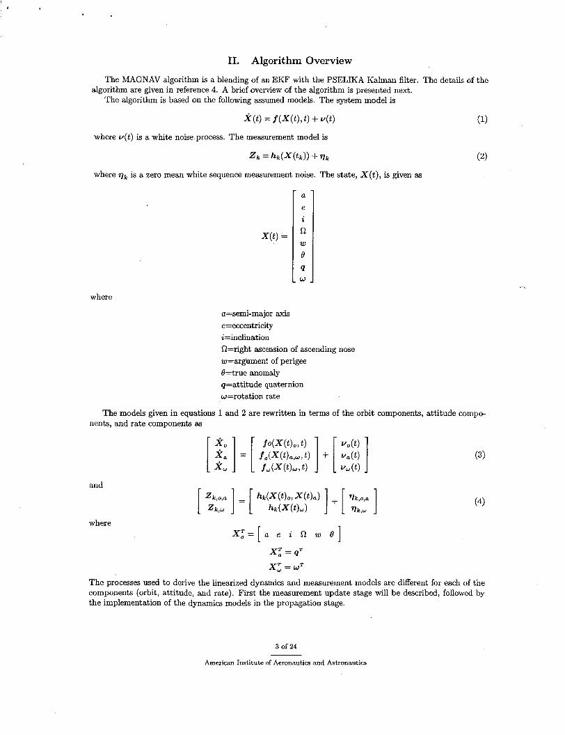
where ?)k is a zero mean white sequence measurement noise. The state, X ( t ) , is given as
where
a=semi-major axis e=eccentricity i=inclination R=right ascension of ascending nose w=argument of perigee Q=true anomaly q=attitude quaternion w=rotation rate
The models given in equations 1 and 2 are rewritten in terms of the orbit components, attitude compo- nents, and rate components as
and
where x : = [ . e i w e ]
x; = q=
x; = WT
The processes used to derive the linearized dynamics and measurement models are different for each of the components (orbit, attitude, and rate). First the measurement update stage will be described, followed by the implementation of the dynamics models in the propagation stage.
3 of 24
American Institute of Aeronautics and Astronautics
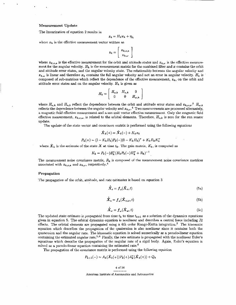
Measurement Update
The linearization of equation 2 results in
where % k is the effective measurement vector written as Z k = H k X k + q k
where %k,o ,a is the effective measurement for the orbit and attitude states and %k,w is the effective measure- ment for the angular velocity. H k is the measurement matrix for the combined filter and 2 contains the orbit and attitude error states, and the angular velocity state. The relationship between the angular velocity and %k, , is linear and therefore x k contains the full angular velocity and not an error in angular velocity. f f k is composed of sub-matrices which reflect the dependence of the effective measurement, % k , on the orbit and attitude error states and on the angular velocity. H k is given as
where H o , k and H a , k reflect the dependence between the orbit and attitude error states and %k,o,a.3 H w , k
reflects the dependence between the angular velocity and %k,w .4 Two measurements are processed alternately, a magnetic field effective measurement and a sun unit vector effective measurement. Only the magnetic field effective measurement, %k,o ,a , is related to the orbital elements. Therefore, H o , k is zero for the sun sensor update.
The update of the state vector and covariance matrix is performed using the following equations
x k ( + ) = X k ( - ) + K k Y k
p k ( + ) = (I - K k H k ) p k ( - ) ( I - K k H k ) T + K k R k K :
where 2, is the estimate of the state x at time t k . The gain matrix, K k , is computed as
K k = % ( - ) H : ( H k p k ( - ) f f z + & ) - I
The measurement noise covariance matrix, R k is composed of the measurement noise covariance matrices associated with %k,o,a and % k , w , respe~tively.~
Propagation
The propagation of the orbit, attitude, and rate estimates is based on equation 3
The updated state estimate is propagated from time t k to time t k + l as a solution of the dynamics equations given in equation 5 . The orbital dynamics equation is nonlinear and describes a central force including 52 effects. The orbital elements are propagated using a 4th order Runge-Kutta integrat i~n.~ The kinematic equation which describes the propagation of the quaternion is also nonlinear since it contains both the quaternion and the angular rate. The kinematic equation is solved numerically as a pseudo-linear equation containing the estimated angular rate.5i6 Finally, the rate estimate is propagated with the nonlinear Euler’s equations which describe the propagation of the angular rate of a rigid body. Again, Euler’s equation is solved as a pseudo-linear equation containing the estimated rate.6
The propagation of the covariance matrix is performed using the following equation
4 of 24
American Institute of Aeronautics and Astronautics
where Q k is the discrete time covariance matrix of u(t) in equation 1 and Ak is the approximated transition matrix. Ak is computed using the following first order Taylor series expansion
A k = I + F k A T
where AT = t k + l - t k . The Jacobian, F , , is computed from f o ( X k , o , t k ) for the orbital components. The details are provided in reference 3. For the attitude states, F k is given by the kinematic equation describing the propagation of the attitude error states.3 A pseudo-linear implementation is applied to the propagation of the attitude error states, since Fk is dependent on the rate. The estimated rates are used in Fk rather than the gyro measured rates. Finally, for the rate states, Fk is provided directly by the pseudo-linear implementation of Euler's equation.6
111. Implementation in the Flight Software
The WIRE attitude control system (ACS) flight software (FSW) executes on an Intel 80386/80387 pro- cessor set. The ACS was designed to provide 1 arc minute pointing accuracy and 6 arc second jitter accuracy using a 3-axis gyro package and a Ball ST-601 star tracker. The attitude estimates are provided by an on- board Kalman filter processing the star tracker and gyro data. Coarse attitude control utilizes a digital sun sensor, 6 coarse sun sensors and a 3-axis magnetometer. The coarse attitude estimates required for coarse control are provided either by an onboard Kalman filter processing the sun sensor, magnetometer, and gyro data, or by a deterministic attitude estimate based on the coarse sun sensor and magnetometer data. Four reaction wheels and three magnetic torque rods serve as the actuators. WIRE is in a 540 km orbit with a 97 degree inclination. During most of the year the spacecraft is in sunlight throughout the entire orbit. During the winter months the spacecraft is in an eclipse for up to 24 minutes of the orbit.
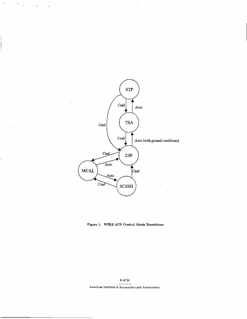
The modes are: safehold (SCSSH), magnetic calibration (MCAL), zenith sun point (ZSP), transitional stellar acquisition (TSA), and stellar point (STP). Figure 1 depicts the transitions for each of the modes, either by command (Cmd) or automatically (auto). The in-flight test of MAGNAV utilized three of the modes, the TSA, STP, and ZSP modes. For the first phase of the testing, WIRE transitioned between the TSA and STP modes. In STP mode target stars are identified and tracked by the star tracker. The onboard attitude estimate is computed in a Kalman filter using the tracked star measurements and the gyro data. The onboard Kalman filter does not estimate a gyro bias. Since WIRE is in a polar orbit, the star tracker is occulted by the earth once per orbit for approximately one third of the orbit. When the star tracker is occulted, the ACS transitions to the TSA mode. In TSA mode, the onboard attitude estimate is propagated with the gyro data until the star measurements are available again. At the end of the star tracker occultation, a command is sent from the ground to begin STP mode and identification of the target stars. During the second phase of testing WIRE remained in the ZSP mode. In this mode the y axis of the spacecraft is pointing at the sun throughout the orbit. The spacecraft rotates at a rate of one revolution per orbit about the sun direction. The control in this mode is coarse. The attitude estimate is computed onboard with a Kalman filter using measurements from a sun sensor, magnetometer, and gyro data.
The MAGNAV algorithm was developed in MATLAB code and first tested on the ground with real sensor data from TRACE and WIRE. The algorithm was converted to C code and tested in a dynamic simulator containing the WIRE ACS. The code was then loaded in three passes to EEPROM and bulk memory in the WIRE onboard computer. Following the uplink of the code, WIRE underwent a cold restart of the ACS computer in the safehold mode. The safehold mode is controlled by a separate electronics box which is responsible for pointing the spacecraft solar arrays at the sun. During safehold, the ACS computer is shut down and the gyros are powered off. A cold restart is the process of starting up the ACS computer and the gyros for the transition out of the safehold mode. The gyro data is the reference for comparing the MAGNAV estimated rates. The onboard attitude estimate is the reference for comparing the MAGNAV estimated attitude. In order to improve the gyro data and the onboard attitude estimates, new gyro biases were estimated after the gyros were turned back on following the cold restart of the ACS computer. Finally, MAGNAV was started on September 4, 2003.
MAGNAV runs as a separate task in the onboard computer, after the ACS tasks. A software patch from the ACS supplies MAGNAV with the sun sensor and magnetometer data for a measurement update nominally every 2 seconds. MAGNAV alternately processes either the sun sensor data or the magnetometer data during an update cycle. MAGNAV propagates the state estimate every 0.5 seconds. Tables are prepared
The WIRE ACS has five control modes.
'
5 of 24
American Institute of Aeronautics and Astronautics
ground conditions)
Figure 1. WIRE ACS Control Mode Transitions
6 of 24
American Institute of Aeronautics and Astronautics
on the ground and uplinked to the ACS with the command to start running MAGNAV and the command to start sending the data packets to MAGNAV. One of the tables contains the initial state estimate for MAGNAV, the initial covariance matrix, the process noise covariance matrix, and the sensor measurement noise covariance matrices. Every third estimated state and covariance matrix diagonal are saved, and then transmitted to the ground with the other WIRE telemetry during the routine contacts with the spacecraft. Frequently during the initial MAGNAV testing the ACS processor would unintentionally shut down and restart, a process called a warm reset, resulting in the loss of the data packets to MAGNAV. MAGNAV was restarted with the ground generated tables following ACS restart events. With MAGNAV running, the onboard processor operated frequently at its full capacity. Sending routine commands to WIRE while simultaneously transmitting all the saved onboard data to the ground, while the computer continued normal processing, caused the warm resets. With a change in some of the routine operational procedures, the frequency of warm resets has decreased.
Following the completion of the second phase of testing MAGNAV, the asteroseismology experiment of the WIRE test-bed began. This experiment involves frequent maneuvers to different target stars, with transitions between the three control modes; TSA, STP, and ZSP. The MAGNAV testing continued simultaneously. Although, in order to accommodate both experiments in the onboard computer, the update frequency of MAGNAV was reduced. Instead of updating with the sensor measurements every 2 seconds, the updates now occur every 3 seconds.
IV. Results of MAGNAV Experiment
This section presents results from the beginning of the MAGNAV experiment through approximately six months of operation. In all cases presented, the MAGNAV estimates are compared to the corresponding estimates available from the WIRE ACS and ground support software. The MAGNAV orbit estimates are compared to a ground based ephemeris. The attitude estimates are compared to the onboard computer (OBC) attitude estimates. In the STP/TSA mode the onboard attitude estimates are based on star tracker and gyro data. During ZSP mode, the onboard attitude estimates are based on sun sensor, magnetometer, and gyro data. Finally, the MAGNAV rate estimates are compared to the gyro data. The first results presented' are from the first phase of the testing, with WIRE in the STP/TSA modes. The next results presented are from the second phase of testing with WIRE in the ZSP mode. Lastly, results are presented from the current state of operations with MAGNAV running simultaneously with the next test-bed experiment, the asteroseismology experiment.
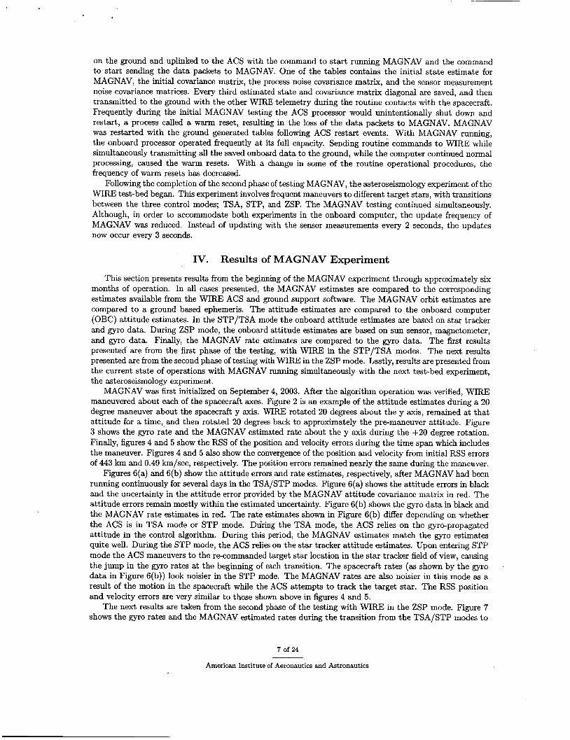
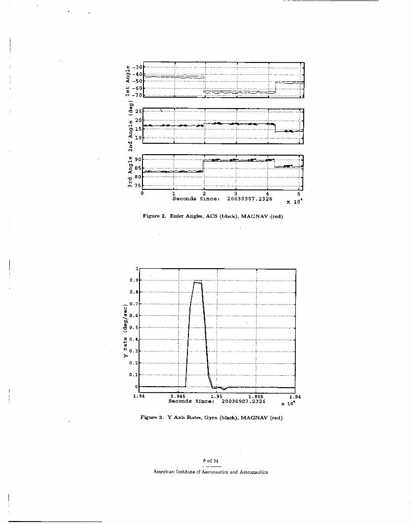
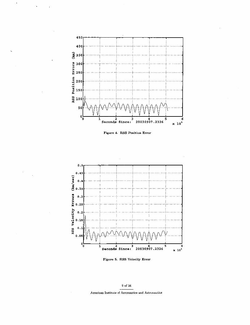
MAGNAV was first initialized on September 4, 2003. After the algorithm operation was verified, WIRE maneuvered about each of the spacecraft axes. Figure 2 is an example of the attitude estimates during a 20 degree maneuver about the spacecraft y axis. WIRE rotated 20 degrees about the y axis, remained at that attitude for a time, and then rotated 20 degrees back to approximately the pre-maneuver attitude. Figure 3 shows the gyro rate and the MAGNAV estimated rate about the y axis during the +20 degree rotation. Finally, figures 4 and 5 show the RSS of the position and velocity errors during the time span which includes the maneuver. Figures 4 and 5 also show the convergence of the position and velocity from initial RSS errors of 443 km and 0.49 km/sec, respectively. The position errors remained nearly the same during the maneuver.
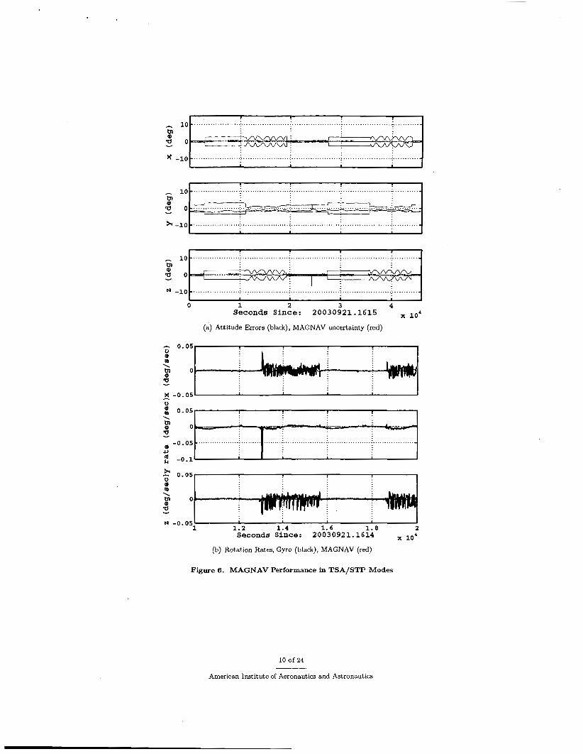
Figures 6(a) and 6(b) show the attitude errors and rate estimates, respectively, after MAGNAV had been running continuously for several days in the TSA/STP modes. Figure 6(a) shows the attitude errors in black and the uncertainty in the attitude error provided by the MAGNAV attitude covariance matrix in red. The attitude errors remain mostly within the estimated uncertainty. Figure 6(b) shows the gyro data in black and the MAGNAV rate estimates in red. The rate estimates shown in Figure 6(b) differ depending on whether the ACS is in TSA mode or STP mode. During the TSA mode, the ACS relies on the gyro-propagated attitude in the control algorithm. During this period, the MAGNAV estimates match the gyro estimates quite well. During the STP mode, the ACS relies on the star tracker attitude estimates. Upon entering STP mode the ACS maneuvers to the re-commanded target star location in the star tracker field of view, causing the jump in the gyro rates at the beginning of each transition. The spacecraft rates (as shown by the gyro data in Figure 6(b)) look noisier in the STP mode. The MAGNAV rates are also noisier in this mode as a result of the motion in the spacecraft while the ACS attempts to track the target star. The RSS position and velocity errors are very similar to those shown above in figures 4 and 5 .
The next results are taken from the second phase of the testing with WIRE in the ZSP mode. Figure 7 shows the gyro rates and the MAGNAV estimated rates during the transition from the TSA/STP modes to
American Institute of Aeronautics and Astronautics
Q) -30 tn -40 2 -50 rl
a 80 & 0 75
................. . j . . . ............... ;. .................. i . . ................ ,j, ................ .:
.................I. .............. ....; ..-.. .T, ... ;. .!. ............. .;
............. e....: ................... 1 .................. : .................. : ................... 1-
....................................... _ .......................................................... i j ,
d N
a g o .................. j .................. rl
.................. :
Figure 2. Euler Angles, ACS (black), MAGNAV (red)
......................
....................
L I 1.94 1.945 1.95 1.955 1.96
Seconds Since: 20030907.2326
Figure 3. Y Axis Rates, Gyro (black), MAGNAV (red)
8 of 24
American Institute of Aeronautics and Astronautics
400 ................ . . . . . . . . . . . . . . . . . . . . . . . . . . . . . . . . . . . . . . . . . . . . . . . . . . . . . . . . . . . . . . . . . . . . . . . . . . . . . . . . . . c 3 50 .............. .f.. .............................. .:. .............. .:, ............. ..;, . . . . . . . . . . . .
Y
................ :. .............. .:. ............... : ................
. . . . . . . . . . . . . . . . f . . . . . . . . . . . . . . . . ................ f . . . . . . . . . . . . . . . .
"0 1 2 3 4 5 6 Seconds Since: 20030907.2326
Figure 4. RSS Position Error
-0 1 2 3 4 5 6 Seconds Since: 20030907.2326
Figure 5. RSS Velocity Error
9 of 24
American Institute of Aeronautics and Astronautics
10 - . .................. .:. ................... :. .................. ..:. ................... _:. .......... - h
tn
- 0.05 m m \ tn O r
3 -
10 - . .................. .:. ................... :. .................. ..:. ................... _:. .......... - h
tn
< a F -
-0 05 0 - c,
h - l o t ...................................................................................................
o b - ! - - c l - - .- . . . . . . . . . . . . . . . . . . . . . . . . . . . . . .....................................................................
................. ...:. .................... ;. .................. ..:. ................... .:.. .........
................... .:. .................... .:. ................... .i,. .................. .:. ..........
0 1 2 3 4
(a) Attitude Errors (black), MAGNAV uncertainty (red)
Seconds Since: 20030921.1615
I X -0.051 I u
0.051 1
N -0.05l 1 1 1.2 1.4 1.6 1.8 2
Seconds Since: 20030921.1614 104
(b) Rotation Rates, Gyro (black), MAGNAV (red)
Figure 6. MAGNAV Performance in TSA/STP Modes
10 of 24
American Institute of Aeronautics and Astronautics
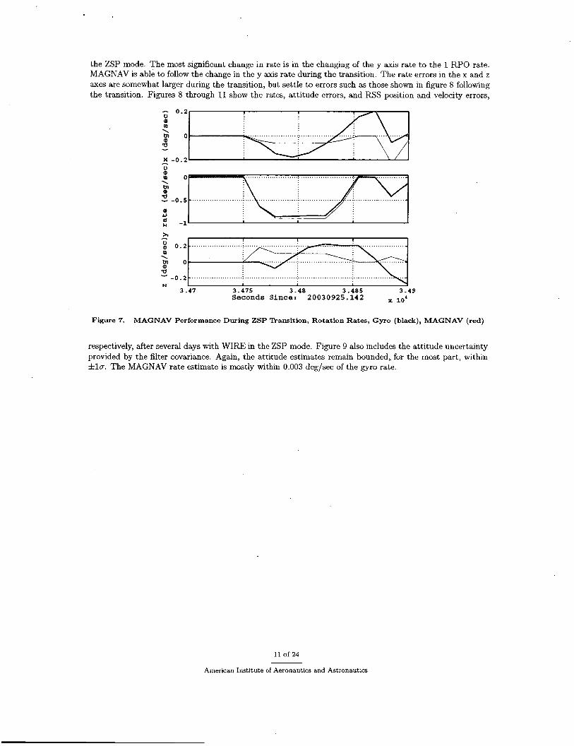
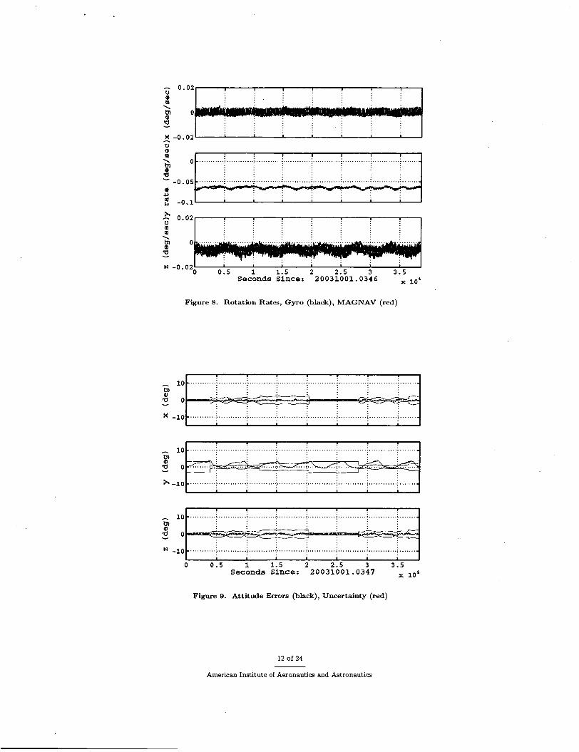
the ZSP mode. The most significant change in rate is in the changing of the y axis rate to the 1 RPO rate. MAGNAV is able to follow the change in the y axis rate during the transition. The rate errors in the x and z axes are somewhat larger during the transition, but settle to errors such as those shown in figure 8 following the transition. Figures 8 through 11 show the rates, attitude errors, and RSS position and velocity errors,
- 0 . 2 a op \ b o m a
x - 0 . 2
- U
3 .47 3.475 3 .48 3 .485 3.49 Seconds Since: 20030925.142 10'
Figure 7. MAGNAV Performance During ZSP Transition, Rotation Rates, Gyro (black), MAGNAV (red)
respectively, after several days with WIRE in the ZSP mode. Figure 9 also includes the attitude uncertainty provided by the filter covariance. Again, the attitude estimates remain bounded,. for the most part, within f la. The MAGNAV rate estimate is mostly within 0.003 deg/sec of the gyro rate.
11 Of 24
American Institute of Aeronautics and Astronautics
- 0.02
x -0.021 I 0 m ‘ 0
a
9)
t ................................. -0.05 -
r) - 2 -0.1’ I
2 0.02 m .
N -0.02’ I 0 0.5 1 1.5 2 2.5 3 3.5
Seconds Since: 20031001.0346
Figure 8. Rotation Rates, Gyro (black), MAGNAV (red)
10 _ ........... ; ............ : ............ : ............ : ............ ; ............ : ............ : ......._ A
.......... . j . . ......... .:. ........... .:. ........... .:. ........... i.. .......... i . . ......... .;. ......
P a - 10 ........... i ............ : ........... ; ............ ; ............ : ............ i ............ ; .......
........... j ........... .:. .......... ..:. ........... .:. ........... ;. ........... i.. ......... .; .......
Seconds Since: 20031001.0347 0 0.5 1 1.5 2 2.5 3 3.5
Figure 9. Attitude Errors (black), Uncertainty (red)
12 of 24
American Institute of Aeronautics and Astronautics
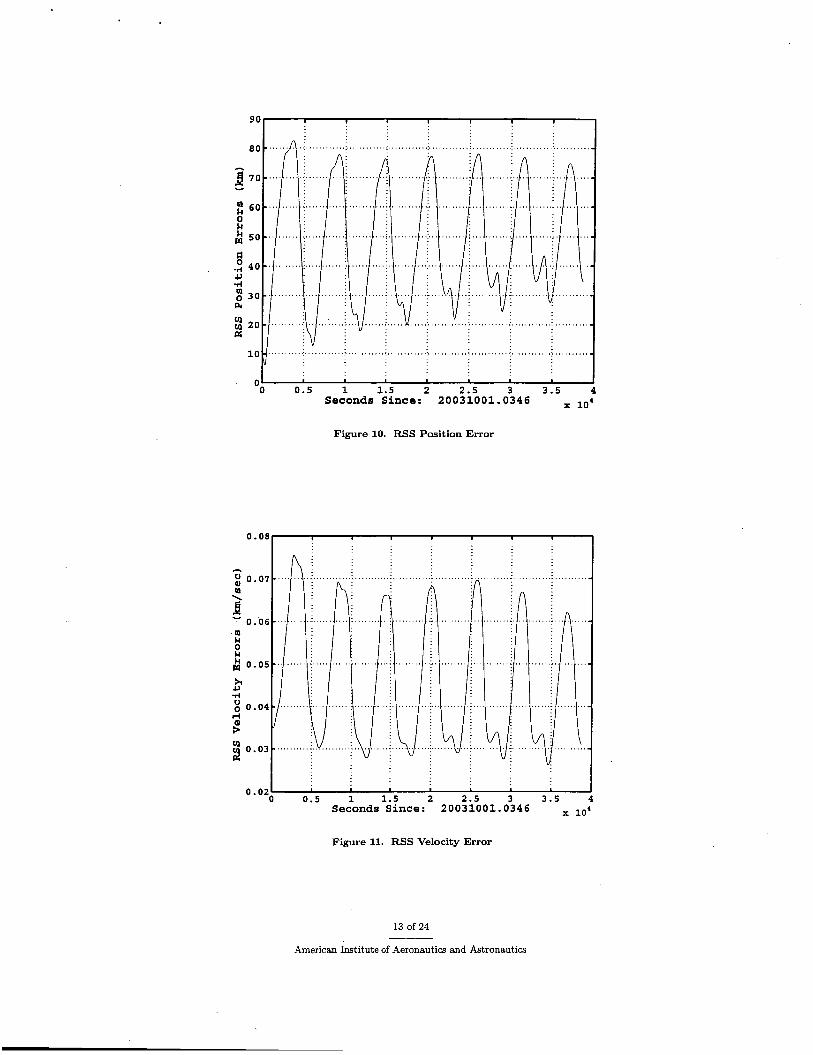
9 0 1 I I I I I
I "0 0 . 5 1 1 . 5 2 2 . 5 3 3 . 5 4
Seconds Since: 20031001.0346
Figure 10. RSS Position Error
0.08
0.07 m
UY v) 0 .03 a
0 . 0 2 0 0 .5 1 1 . 5 2 2 .5 3 3 . 5 4
Second8 Since: 20031001.0346
Figure 11. RSS Velocity Error
13 of 24
American Institute of Aeronautics and Astronautics
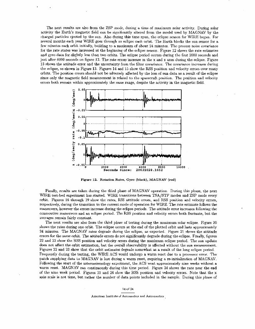
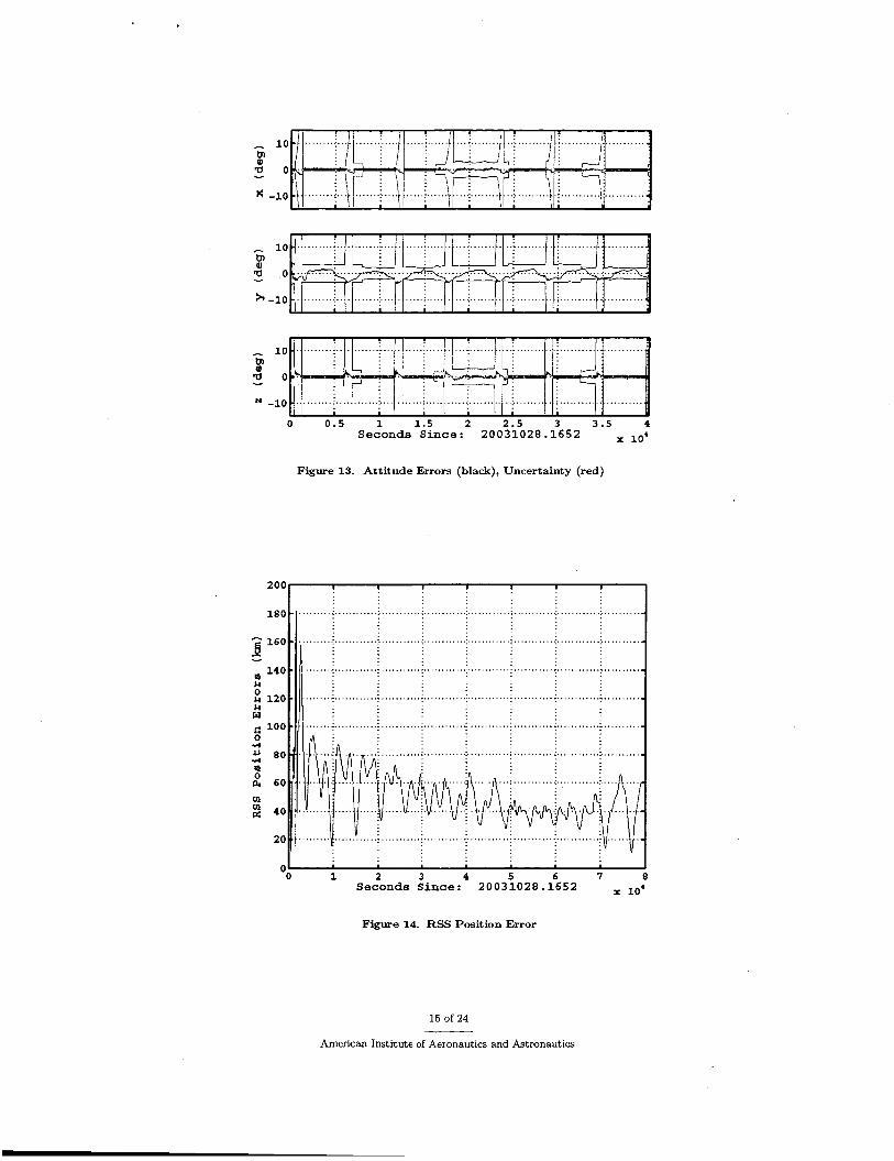
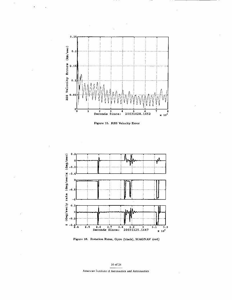
The next results are also from the ZSP mode, during a time of maximum solar activity. During solar activity the Earth's magnetic field can be significantly altered from the model used by MAGNAV by the charged particles ejected by the sun. Also during this time span, the eclipse season for WIRE began. For several months each year WIRE goes through an eclipse each orbit. The Earth blocks the sun sensor for a few minutes each orbit initially, building to a maximum of about 24 minutes. The process noise covariance for the rate states was increased at the beginning of the eclipse season. Figure 12 shows the rate estimates and gyro data for slightly less than two orbits. The eclipse period occurs during the first 2000 seconds and just after 6000 seconds on figure 12. The rate errors increase in the x and z axes during the eclipse. Figure 13 shows the attitude error and the uncertainty from the filter covariance. The covariance increases during the eclipse, as shown in Figure 13. Figures 14 and 15 show the RSS position and velocity errors over many orbits. The position errors should not be adversely affected by the loss of sun data as a result of the eclipse since only the magnetic field measurement is related to the spacecraft position. The position and velocity errors both remain within approximately the same range, despite the activity in the magnetic field.
\
a p 0 -
- 0 . 0 5 PI \
P o a Y
-.................. i ................... i ................... j ................... i ..................~
P \ L n o PI a Y
N -0 .05 ' ' I 0 2 0 0 0 4000. 6000 8000 10000
Seconds Since: 20031028.1652
Figure 12. Rotation Rates, Gyro (black), MAGNAV (red)
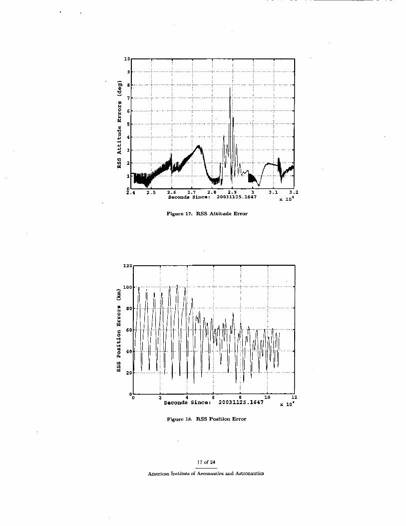
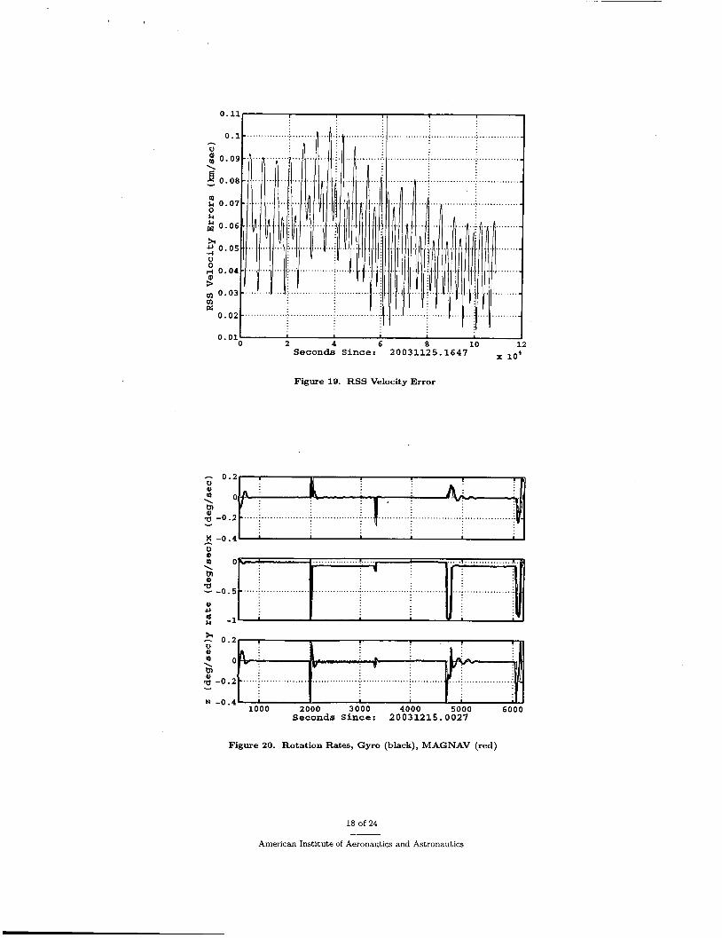
Finally, results are taken during the third phase of MAGNAV operation. During this phase, the next WIRE test-bed experiment has started. WIRE transitions between TSA/STP modes and ZSP mode every orbit. Figures 16 through 19 show the rates, RSS attitude errors, and RSS position and velocity errors, respectively, during the transition to the current mode of operation for WIRE. The rate estimate follows the maneuvers, however the errors increase during the eclipse periods. The attitude error increases following the consecutive maneuvers and an eclipse period. The RSS position and velocity errors both fluctuate, but the averages remain fairly constant.
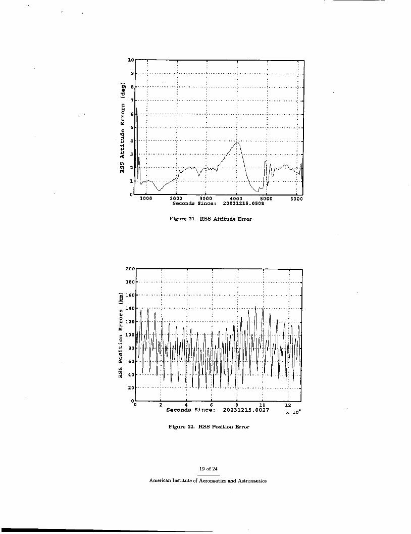
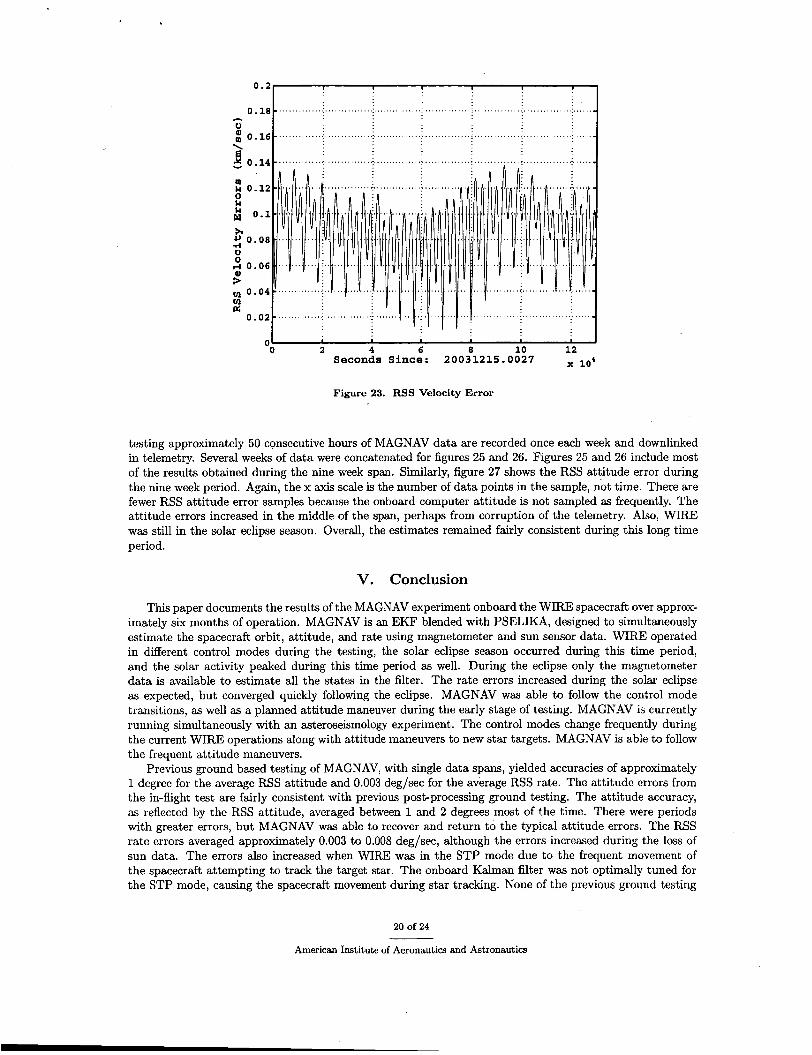
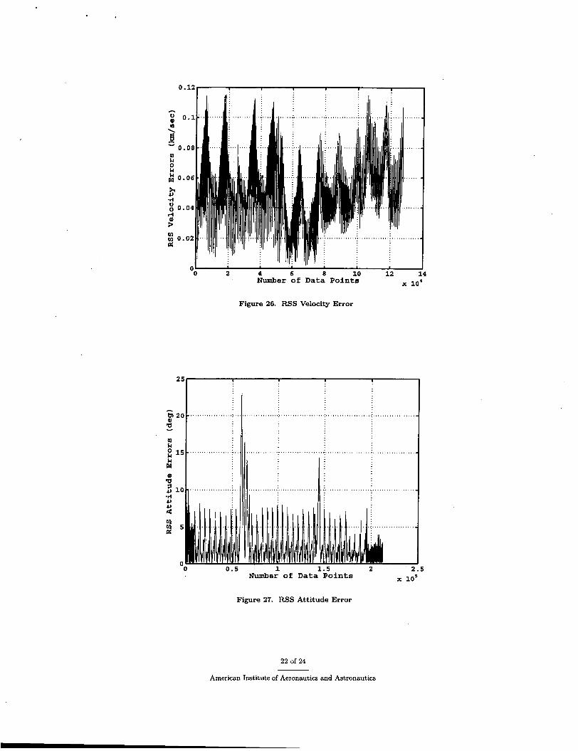
The next results are also from the third phase of testing during the maximum solar eclipse. Figure 20 shows the rates during one orbit. The eclipse occurs at the end of the plotted orbit and lasts approximately 24 minutes. The MAGNAV rates degrade during the eclipse, as expected. Figure 21 shows the attitude errors for the same orbit. The attitude errors do not significantly degrade during the eclipse. Finally, figures 22 and 23 show the RSS position and velocity errors during the maximum eclipse period. The sun update does not affect the orbit estimation, but the overall observability is affected without the sun measurement. Figures 22 and 23 show that the orbit estimates degrade somewhat as a result of the long eclipse period. Frequently during the testing, the WIRE ACS would undergo a warm reset due to a processor error. The patch supplying data to MAGNAV is lost during a warm reset, requiring a reinitialization of MAGNAV. Following the start of the asteroseismology experiment, the ACS went approximately nine weeks without a warm reset. MAGNAV ran continuously during this time period. Figure 24 shows the rate near the end of the nine week period. Figures 25 and 26 show the RSS position and velocity errors. Note that the x axis scale is not time, but rather the number of data points included in the sample. During this phase of
14 of 24
American Institute of Aeronautics and Astronautics
0 0 .5 1 1 . 5 2 2 . 5 3 3 . 5 4 Seconds Since: 20031028.1652
Figure 13. Attitude Errors (black), Uncertainty (red)
1 1 2 3 4 5 6 7 8
Seconds Since: 20031028.1652
Figure 14. RSS Position Error
15 of 24
American Institute of Aeronautics and Astronautics
0 . :
z 0 . : 0 k k Ltl
sr 2 0 . u
I I I
................................................
.. .............................................
1 2 3 Seconds Since: 20031028.1652
Figure 15. RSS Velocity Error
Figure 16. Rotation Rates, Gyro (black), MAGNAV (red)
16 of 24
American Institute of Aeronautics and Astronautics
h
F
E
a Y
0 $4 $4 w QI a s & -rl &
2 v1 v1 rr:
m $4 0 $4 $4 w fi 0 rl & rl m 0 PI v1 v1 rr:
9 .......... ' ... . . . . . . . . . ) . . . . . . . . . . . i . ........................ j . . . . . . . . . . . . :.... ........ ) . 1 8
.......... ............ ; ... . . . . . . . . ; ............ : ....... . . . . . . . : ............ ; .. . . . . . . .
2.4 2.5 2.6 2.7 2.8 2.9 3 3.1 2 io4 Seconds Since: 20031125.1647
Figure 17. RSS Attitude Error
Y 3
I I 0 2 4 6 8 10 12
Seconds Since: 20031125.1647 0 1
Figure 18. RSS Position Error
17 of 24
American Institute of Aeronautics and Astronautics
0.01' 0 2 4 6 8 10
Seconds Since: 20031125.1647
Figure 19. RSS Velocity Error
........... :.... ............. :...... v
Y -0 A
...................... ........................ 0, 0 0 1
P 2 -0.5 .....; ................................. ; ............................. ...; ................... P) 11
-1
Figure 20. Rotation Rates, Gyro (black), MAGNAV (red)
18 of 24
American Institute of Aeronautics and Astronautics
10 1 1 1 9 I 1
Figure 21. RSS Attitude Error
0 7. 4 6 8 10 12 ~~
Seconds Since: 20031215.0027
Figure 22. RSS Position Error
19 of 24
American Institute of Aeronautics and Astronautics
I 0 2 4 6 8 10 12
Seconds Since: 20031215.0027
Figure 23. RSS Velocity Error
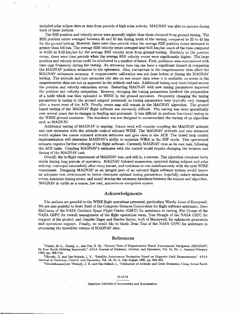
testing approximately 50 consecutive hours of MAGNAV data are recorded once each week and downlinked in telemetry. Several weeks of data were concatenated for figures 25 and 26. Figures 25 and 26 include most of the results obtained during the nine week span. Similarly, figure 27 shows the RSS attitude error during the nine week period. Again, the x axis scale is the number of data points in the sample, not time. There are fewer RSS attitude error samples because the onboard computer attitude is not sampled as frequently. The attitude errors increased in the middle of the span, perhaps from corruption of the telemetry. Also, WIRE was still in the solar eclipse season. Overall, the estimates remained fairly consistent during this long time period.
V. Conclusion
This paper documents the results of the MAGNAV experiment onboard the WIRE spacecraft over approx- imately six months of operation. MAGNAV is an EKF blended with PSELIKA, designed to simultaneously estimate the spacecraft orbit, attitude, and rate using magnetometer and sun sensor data. WIRE operated in different control modes during the testing, the solar eclipse season occurred during this time period, and the solar activity peaked during this time period as well. During the eclipse only the magnetometer data is available to estimate all the states in the filter. The rate errors increased during the solar eclipse as expected, but converged quickly following the eclipse. MAGNAV was able to follow the control mode transitions, as well as a planned attitude maneuver during the early stage of testing. MAGNAV is currently running simultaneously with an asteroseismology experiment. The control modes change frequently during the current WIRE operations along with attitude maneuvers to new star targets. MAGNAV is able to follow the frequent attitude maneuvers.
Previous ground based testing of MAGNAV, with single data spans, yielded accuracies of approximately 1 degree for the average RSS attitude and 0.003 deg/sec for the average RSS rate. The attitude errors from the in-flight test are fairly consistent with previous post-processing ground testing. The attitude accuracy, as reflected by the RSS attitude, averaged between 1 and 2 degrees most of the time. There were periods with greater errors, but MAGNAV was able to recover and return to the typical attitude errors. The RSS rate errors averaged approximately 0.003 to 0.008 deg/sec, although the errors increased during the loss of sun data. The errors also increased when WIRE was in the STP mode due to the frequent movement of the spacecraft attempting to track the target star. The onboard Kalman filter was not optimally tuned for the STP mode, causing the spacecraft movement during star tracking. None of the previous ground testing
20 of 24
American Institute of Aeronautics and Astronautics
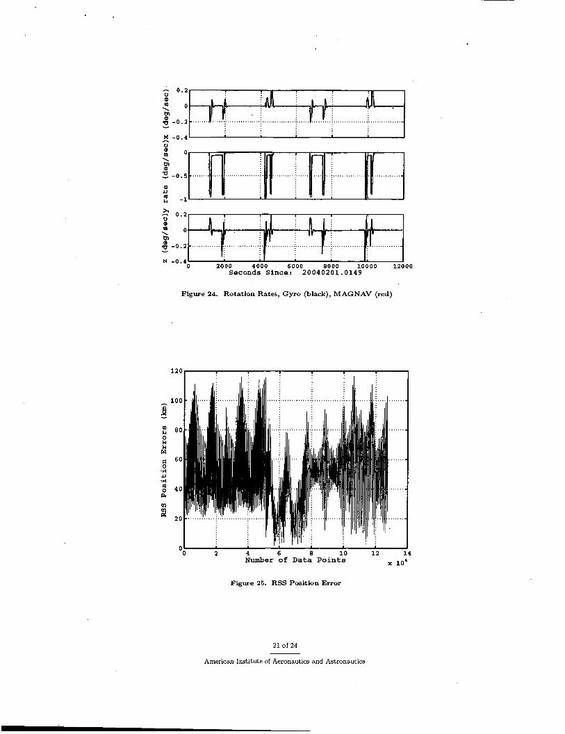
N -0 .4 ' I I 0 2 0 0 0 4000 6 0 0 0 8000 1 0 0 0 0 12000
Seconds Since: 20040201.0149
Figure 24. Rotation Rates, Gyro (black), MAGNAV (red)
3
0 2 4 6 8 10 12 0'
4
x 10' Number of Data Points
Figure 25. RSS Position Error
21 of 24
American Institute of Aeronautics and Astronautics
I, '
2 4 6 8 1 0 12 - _ _ I Number of D a t a Poinca- 10'
Figure 26. RSS Velocity Error
I
"0 0 . 5 1 1.5 2 2 .5 i o 5 Number of D a t a P o i n t s
Figure 27. RSS Attitude Error
22 of 24
American Institute of Aeronautics and Astronautics
included solar eclipse data or data from periods of high solar activity. MAGNAV was able to operate during both of these periods.
The RSS position and velocity errors were generally higher than those obtained from ground testing. The RSS position errors averaged between 45 and 60 km during much of the testing, compared to 25 to 40 km for the ground testing. However, there were time periods when the average RSS position errors increased to greater than 100 km. The average RSS velocity errors averaged near 0.05 km/sec much of the time compared to 0.025 to 0.03 km/sec for the average RSS velocity error from ground testing. Similarly to the position errors, there were time periods when the average RSS velocity errors were significantly higher. The large position and velocity errors could be attributed to a number of issues. First, problems were encountered with time tags frequently during the testing. An erroneous time tag can have a significant impact in comparing the MAGNAV position estimates to the ephemeris. Also, corruptions in the magnetometer data affect the MAGNAV estimation accuracy. A magnetometer calibration was not done before or during the MAGNAV testing. The attitude and rate estimates rely also on sun sensor data when it is available, so errors in the magnetometer data are not as apparent in the attitude and rate. Additional tuning may have helped reduce the position and velocity estimation errors. Restarting MAGNAV with new tuning parameters improved the position and velocity estimation. However, changing the tuning parameters involved the preparation of a table which was then uploaded to WIRE by the ground operators. Frequently changing the tuning parameters is taxing to the ground support personnel, so tuning parameters were typically only changed after a warm reset of the ACS. Finally, errors may still remain in the MAGNAV algorithm. The ground based testing.of the MAGNAV flight software was extremely difficult. The testing was done sporadically over several years due to changes in funding and personnel. It was difficult to perform functional testing in the WIRE ground simulator. The simulator was not designed to accommodate the testing of an algorithm such as MAGNAV.
Additional testing of MAGNAV is ongoing. Future work will consider coupling the MAGNAV attitude and rate estimates with the attitude control onboard WIRE. The MAGNAV attitude and rate estimates would replace the coarse onboard attitude estimates and gyro data in the ACS. The closed loop control implementation will determine MAGNAV’s ability to maintain WIRE in the ZSP mode. This operational scenario requires further redesign of the fight software. Currently MAGNAV runs as its own task, following the ACS tasks. Coupling MAGNAV’s estimates with the control would require changing the location and timing of the MAGNAV task.
Overall, the in-flight experiment of MAGNAV was, and still is, a success. The algorithm remained fairly stable during long periods of operation. MAGNAV followed maneuvers, operated during eclipses and solar activity, converged successfully after every restart, and continues to run simultaneously with the next WIRE experiment. Designing MAGNAV as & integral part of an onboard flight software system would ensure an adequate test environment to better determine optimal tuning parameters, hopefully reduce estimation errors, minimize timing errors, and would develop the necessary interfaces between the sensors and algorithm. MAGNAV is viable as a coarse, low cost, autonomous navigation system.
Acknowledgments
The authors are grateful to the WIRE flight operations personnel, particulary Wendy Jones of Honeywell. We are also grateful to Scott Snell of the Computer Sciences Corporation for flight software assistance, Dave McComas of the NASA Goddard Space Flight Center (GSFC) for assistance in testing, Pat Crouse of the NASA GSFC for overall management of the flight operations team, Tom Stengle of the NASA GSFC for support of the project, and Jennifer Sager and Maxine Saylor, both of Honeywell, for ephemeris generation and operations support. Finally, we would like to thank Dean Tsai of the NASA GSFC for assistance in processing the incredible volume of MAGNAV data.
References
‘Psiaki, M. L., Huang, L., and Fox, S. M., “Ground Tests of Magnetometer Based Autonomous Navigation (MAGNAV) for Low Earth Orbiting Spacecraft,” AIAA Journal of Guidance, Control, and Dynamics, Vol. 16, No. 1, January-February 1993, pp. 206-214.
*Shorshi, G. and Bar-Itshack, I. Y., “Satellite Autonomous Navigation Based on Magnetic Field Measurements,” AIAA Journal of Guidance, Control, and Dynamics, Vol. 18, No. 4, July-August 1995, pp. 843-850.
3Deutschmann(now Thienel), J. K. and Bar-Itshack, I., “Evaluation of Attitude and Orbit Estmation Using Actual Earth
23 of 24
American Institute of Aeronautics and Astronautics
Magnetic Field Data,” AIAA Journal of Guidance, Control, and Dynamics, Vol. 24, No. 3, May-June 2001, pp. 616-626. 4Deutschmann(now Thienel), J. K., Harman, R. R., and Bar-Itahack, I., “An Innovative Method for Low Cost, Autonomous
Navigation for Low Earth Orbit Satellites,” AIAA/AAS Astrodynamics Specialist Conference, No. AIAA-98-4183, Boston, Massachusetts, August 1998.
5Hasman, R. R. and Bar-Itahack, I. Y., “Pseudolinear and State-Dependent Riccati Equation Filters for Angular Rate Estimation,” AIAA Journal of Guidance, Control, and Dynamics, Vol. 22, No. 5, September-October 1999, pp. 723-723.
6Azor, R., Bar-Itahack, I., Harman R. R., and Deutschmann(now Thienel), J. K., “Angular-Rate Estimation Using Delayed Quaternion Messurements,” AIAA Journal of Guidance, Control, and Dynamics, Vol. 24, No. 3, May-June 2001, pp. 436-443.
24 of 24
American Institute of Aeronautics and Astronautics