response characteristics of the deepcwind floating wind
TRANSCRIPT

Response characteristics of the DeepCwind floating wind turbinemoored by a Single-Point Mooring system
Downloaded from httpsresearchchalmersse 2022-01-29 0641 UTC
Citation for the original published paper (version of record)[Person 914c9b49-6ea3-4f85-8bfd-5ea2ba6418ed not found] [Person
NB When citing this work cite the original published paper
researchchalmersse offers the possibility of retrieving research publications produced at Chalmers University of TechnologyIt covers all kind of research output articles dissertations conference papers reports etc since 2004researchchalmersse is administrated and maintained by Chalmers Library
(article starts on next page)
applied sciences
Article
Response Characteristics of the DeepCwind FloatingWind Turbine Moored by a Single-Point Mooring System
Yingyi Liu 1 Shigeo Yoshida 1 Hiroshi Yamamoto 2 Akinori Toyofuku 2 Guanghua He 3
and Shunhan Yang 4
1 Research Institute for Applied Mechanics Kyushu University Kasuga 8168580 Japanyoshidasriamkyushu-uacjp
2 Interdisciplinary Graduate School of Engineering Sciences Kyushu University Kasuga 8168580 Japanyamamotohriamkyushu-uacjp (HY) toyofukuariamkyushu-uacjp (AT)
3 School of Naval Architecture and Ocean Engineering Harbin Institute of Technology Weihai 264209 Chinaghhehitwheducn
4 Department of Mechanics and Maritime Sciences Chalmers University of TechnologySE-412 96 Gothenburg Sweden shunhanyangchalmersse
Correspondence liuyingyiriamkyushu-uacjp Tel +81-808-565-7934
Received 19 October 2018 Accepted 16 November 2018 Published 20 November 2018
Abstract In recent years the SPM (Single-Point Mooring) concept has been widely employedin several branches of the naval architecture and marine engineering field such as FPSOs(Floating Production Storage and Offloading units) offshore oil rigs etc but not yet popularin the offshore wind energy To investigate the response characteristics of an SPM-moored FWT(Floating Wind Turbine) in the present work we perform a numerical study on the DeepCwindsemisubmersible wind turbine using the state-of-the-art open-source tool FAST The free-decay testresults show that the SPM layout affects the natural periods of the wind turbine in rotational modesas well as the mooring stiffness of the diagonal rotational and crossing rotational-translational termsespecially in relation to the yaw mode Comparisons of the RAOs (Response Amplitude Operators)elucidate that the presence of wind influences significantly the sway roll and yaw motions of theSPM layout Finally the weathervane test shows that an asymmetry exists in the free-yaw motionresponse when the semisubmersible wind turbine is moored by an SPM system
Keywords single-point mooring semisubmersible coupled dynamics
1 Introduction
OWE (Offshore Wind Energy) is a promising substitution of the traditional fossil fuels in the futureIn recent years the OWE technology is witnessing a booming development in which a variety of newconceptual designs have been realized [1ndash4] The mooring system as an essential part of the floatingsystem for station keeping is undergoing a quick update on the technology One of the most recentdevelopments is the concept of an FWT (Floating Wind Turbine) moored by an SPM (Single-PointMooring) system [5ndash7] Iijima et al [5] designed a sample of an SPM-moored semisubmersible FWTand carried out a 1100 scaled model test on the wave basin Furthermore it was observed that theFWT was capable of weathervaning Koh et al [6] performed a numerical analysis of a single-pointmoored TLS (Tension Leg Spar) and found that the TLS also could self-adjust its orientation to theinflow wind direction Nihei et al [7] carried out a tank model test of two different SPM bearing typesand demonstrated that the combination usage of thrust bearing and aligning bearing perform betterthan using only the thrust bearing From a technical point of view the application of an SPM systemenables the FWT to have free-yaw motions when the wind changes direction which can be viewed as
Appl Sci 2018 8 2306 doi103390app8112306 wwwmdpicomjournalapplsci
Appl Sci 2018 8 2306 2 of 20
a passive yaw control system In comparison to the active yaw control system normally installed in theturbine nacelle the advantages of utilization of SPM can be generally summarized into the followingtwo aspects
bull To reduce the cost of construction and the heavy weight due to the existence of nacelle yaw controlsystem and the associated mechanical bearings and brakes at the tower top of wind turbine
bull To avoid the failure of a nacelle yaw system due to some sudden electricity-based accident orlong-term corrosion caused by the humid salt-laden air in the sea circumstance
SPM technology was firstly deployed in the offshore oil engineering involving some FPSOs(Floating Production Storage and Offloading units) and oil rigs [8ndash12] FPSOs have been successfullyinstalled in North Sea Brazil Mediterranean Sea etc for offshore oil exploitations and are moored in avariety of sea-depth regions from shallow water (around 30 m) to ultra-deep water (2000ndash3000 m) [12]The SPM systems applied in FPSOs are usually turret-mooring systems in which the presence of a largenumber of risers results in large-diameter turrets [13] The weathervane capability of the SPM helpsthe self-adjusted FPSOs to be wave-aligned and therefore significantly reduces the wave impact on theFPSOs in harsh sea circumstances due to the green water loadings etc [14] In recent years the SPMtechnology has also been introduced into WECs (Wave Energy Converters) Eg Thomsen et al [1516]tested and discussed the applicability of using SPM systems in the floating WECs and compared itsmerits and demerits with other mooring concepts in order to reach an optimization of the levelizedcost of energy
The main objective of the present research is to investigate the characteristic behaviors of asemisubmersible FWT moored by an SPM system The present work aims to reveal in which way theSPM system affects the dynamic response of a semisubmersible-type FWT A comparative study isundertaken in the meantime with the MPM (Multiple-Point Mooring) system to conduct the analysisand draw meaningful conclusions The research is done with the aid of a well-proven reliablenumerical simulation software FAST (Fatigue Aerodynamics Structures and Turbulence) FASTis the NRELrsquos (National Renewable Energy Laboratoryrsquos) primary open-source CAE (Computer AidedEngineering) tool for simulating the coupled aero-hydro-servo-elastic dynamic response of windturbines It is based on advanced engineering models which are derived from fundamental lawsbut with appropriate simplifications and assumptions and supplemented where applicable withcomputational solutions and test data [17] In the present research the latest FAST version 816 is usedThis version has been developed based on the new modularization framework [1819] to improvethe overall modularity In addition in accordance with FAST version 816 several useful utilitiesand tool boxes written in Python and Matlab are also used for the purposes of pre-processing andpost-processing In the subsequent parts Section 2 presents the theories of the quasi-static and dynamicmooring modelling approaches for station keeping of the FWTs Section 3 describes in detail aboutthe models of floating structure wind turbine and mooring layouts Section 4 presents importantcomputation results followed by analysis and discussions the final conclusions are summarized inSection 5
2 Mathematical Equations of the Coupled Dynamics Theory of a Moored FWT
Equations of motion of a moored FWT can be derived based on the Kanersquos equation [20ndash22] takinginto consideration of all nonlinearities and systemrsquos DOFs (Degrees of Freedom) Kanersquos equationis generally based on the principle that all generalized active forces and inertial forces acting onthe complex system of the coupled rotor-nacelle assembly the tower and the support platform arebalanced The kinetics equations for the support platform include contributions from the platformmass and inertia gravity hydro-restoring hydrodynamics and the reaction forces of the mooringsystem which can be written as
FPlat f ormi (q) = minus
(Mij + Aij
) qj minus
tint0
Kij(t minus τ)qj(τ)dτ minus CHydrostatic
ij qj + FWavesi (q) + FLines
i (q) + ρgVδi3 (1)
Appl Sci 2018 8 2306 3 of 20
where Mij Aij and CHydrostaticij are the (i j) component of the platform mass matrix impulsive
hydrodynamic added-mass matrix and hydrostatic-restoring matrix respectively qj is the jth DOF ofthe platform motions FWaves
i represents the total excitation load on the support platform from incidentwaves Kij is the (i j) component of the matrix known as the wave-radiation-retardation kernelor impulse-response functions the last term on the right-hand side of Equation (1) represents thebuoyancy force of the platform derived from Archimedesrsquo principle in which ρ is the water densityg is the gravity acceleration V is the displaced volume of water by the immersed part of the platformδi3 is the (i 3) component of the KroneckerndashDelta function FLines
i is the ith component of the load onplatform from all mooring lines
It can be noted that the first three terms on the right-hand side of Equation (1) are all linear tothe platform acceleration velocity and displacement respectively FWaves
i and FLinesi can be linear
or nonlinear depending on the requisite modelling complexity For a generic problem usuallyup to second-order wave forces are considered for the potential flow theory It is sometimessupplemented by the Morison-strip theory in the case there exist slender braced members in thefloating platform structure (which is also nonlinear) FLines
i is usually modelled by a quasi-staticmethod eg the improved catenary theory [22] to calculate the tension force of every mooring lineand them make a summation of them When no portion of the line rests on the seabed the analyticalformulation of each line is as follows
xF(FH FV) =FHw
ln
FVFH
+
radic1 +
(FVFH
)2minus ln
FV minus wLFH
+
radic1 +
(FV minus wL
FH
)2+
FH LEA
(2)
zF(FH FV) =FHw
radic1 +(
FVFH
)2minus
radic1 +
(FV minus wL
FH
)2+
1EA
(FV L minus wL2
2
) (3)
where xF and zF are respectively the horizontal and vertical coordinates of the fairlead positionrelative to the anchor FH and FV are the horizontal and vertical components of the effective tensionin the mooring line at the fairlead w is the mass of the mooring line per unit length L is the totalunstretched mooring line length and EA is the sectional stiffness of the mooring line It is worthnoting that Equations (2) and (3) should be solved iteratively in the local coordinate system via theNewtonndashRaphson method etc
When the environment conditions are severe or if the floating platform has large responseshigh-fidelity mooring line models are recommended for the mooring analysis especially forprediction of the mooring line loads The existing high-fidelity models include FEA-based models andlumped-mass models It appears that although the FEA-based models can reach a good accuracy inprediction of the loads over a wide range of conditions they are not computationally cost-effective [23]In a lumped-mass model the cable mass is discretized into point masses at every separate node byassigning it half of the combined mass of two adjacent cable segments The complete equation ofmotion for each node i is [23]
(mi + ai)ri = Ti+(12) minus Timinus(12) + Bi+(12) minus Biminus(12) + Wi + Fi + Dpi + Dqi (4)
where mi and ai stands for the mass and added mass assigned at the node i T and B stands for theinternal stiffness and damping W and F stands for the line net buoyancy and seabed contact Dp andDq stands for the hydrodynamic drag force in the transverse and tangential directions respectivelyAll of the above symbols in bold are 3 times 3 matrices
Regarding the difference of the two mooring-line modelling methods studies have been donepreviously by many other researchers Thomsen et al [15] stated that a quasi-static approach is notsuitable to study the dynamic behavior of WECs when the mooring has significant nonlinearitieseg especially for synthetic ropes It was later proved by their experimental testing of moorings for
Appl Sci 2018 8 2306 4 of 20
large floating wave energy converters in the wave basin at Aalborg University in which a large 52deviation was found by comparing with their measured line tension [24] Hall et al [25] concludedthat mooring dynamics have an influence on platform motions only when those motions are largebut are always important to the prediction of mooring line loads Wendt et al [26] performed athorough quantified comparison between the dynamic mooring and the quasi-static methods showingthat the lumped-mass method predicts smaller platform motions but larger mooring line tensions inthe extensive presented results
3 Model Development of the Semisubmersible-Type FWTs
31 Floating Structure Model
In the present research the DeepCwind semi-submersible [27] is employed as the supportingplatform or the floater since it has been extensively tested in the USndashbased OC4 project [2829]aiming at generating test data for use in validating floating offshore wind turbine modelling toolsThe semisubmersible as shown in Figure 1 is mainly composed by a central column and three outeroffset columns having a sound feature that heave plates (the base columns) are attaching to thebottom of the upper columns in order to prevent large heave motions of the platform A host ofslender bracings are also applied to connect between the columns and make the floating structurestiff Geometrical specifications of the DeepCwind semi-submersible are listed in Table 1 More detailscan be found in Reference [27]
Appl Sci 2018 8 x 4 of 20
suitable to study the dynamic behavior of WECs when the mooring has significant nonlinearities eg especially for synthetic ropes It was later proved by their experimental testing of moorings for large floating wave energy converters in the wave basin at Aalborg University in which a large 52 deviation was found by comparing with their measured line tension [24] Hall et al [25] concluded that mooring dynamics have an influence on platform motions only when those motions are large but are always important to the prediction of mooring line loads Wendt et al [26] performed a thorough quantified comparison between the dynamic mooring and the quasi-static methods showing that the lumped-mass method predicts smaller platform motions but larger mooring line tensions in the extensive presented results
3 Model Development of the Semisubmersible-Type FWTs
31 Floating Structure Model
In the present research the DeepCwind semi-submersible [27] is employed as the supporting platform or the floater since it has been extensively tested in the USndashbased OC4 project [2829] aiming at generating test data for use in validating floating offshore wind turbine modelling tools The semisubmersible as shown in Figure 1 is mainly composed by a central column and three outer offset columns having a sound feature that heave plates (the base columns) are attaching to the bottom of the upper columns in order to prevent large heave motions of the platform A host of slender bracings are also applied to connect between the columns and make the floating structure stiff Geometrical specifications of the DeepCwind semi-submersible are listed in Table 1 More details can be found in Reference [27]
Figure 1 The 150 model scale semisubmersible in the DeepCwind tank tests [2730]
Hydrodynamics modelling for the supporting platform can be implemented in HydroDyn [31] which is a FAST built-in module HydroDyn allows for multiple approaches in calculating the hydrodynamic loads on a structure For the DeepCwind semisubmersible that consists of both large-diameter columns and slender bracing members a general strategy is to apply the potential-flow theory solution to the former and the Morison strip-theory solution to the latter similar to that have been done in Reference [32]
Figure 1 The 150 model scale semisubmersible in the DeepCwind tank tests [2730]
Hydrodynamics modelling for the supporting platform can be implemented in HydroDyn [31]which is a FAST built-in module HydroDyn allows for multiple approaches in calculating thehydrodynamic loads on a structure For the DeepCwind semisubmersible that consists of bothlarge-diameter columns and slender bracing members a general strategy is to apply the potential-flowtheory solution to the former and the Morison strip-theory solution to the latter similar to thathave been done in Reference [32]
Appl Sci 2018 8 2306 5 of 20
Table 1 Geometrical specifications of the DeepCwind semisubmersible platform
Platform Properties Value
Platform draft 200 mCenterline spacing between offset columns 500 m
Length of upper columns 260 mLength of base columns 60 m
Diameter of main column 65 mDiameter of offset (upper) columns 120 m
Diameter of base columns 240 mDiameter of pontoons and cross braces 16 m
32 Wind Turbine Model
The NREL 5-MW baseline wind turbine is placed atop the DeepCwind semisubmersible It hasa three-bladed rotor with a diameter of 126 m and a cylindrical tower with a hub height of 90 mTo control the baseline wind turbine a variable-speed variable blade-pitch-to-feather configurationis applied Selected key properties for the wind speed and the mass distribution of the NREL 5-MWbaseline wind turbine are listed in Table 2 More details can be found in Reference [22]
The aerodynamics of the baseline wind turbine involving the aerodynamics of the rotor bladesthe nacelle and the tower can be modelled by the AeroDyn module of the FAST code The structuraldeflections of the blades and the tower can be modelled by the ElastoDyn module FAST can also belinked to a Bladed-style DLL (Dynamic Link Library) which is called by its ServoDyn module tocontrol the wind turbine model in the real time
Table 2 Selected properties of the NREL 5-MW baseline wind turbine
Turbine Properties Value
Rotor configuration Upwind 3 BladesCut-in wind speed 3 msRated wind speed 114 ms
Cut-out wind speed 25 msRotor mass 110000 kg
Nacelle mass 240000 kgTower mass 347460 kg
33 Mooring System Models
The station keeping of the platform is provided by three slack catenary chain mooringsIn the multi-point mooring system the fairleads of the mooring lines are located at the top of the basecolumns at a depth of 140 m below the mean sea level and at a radius of 4087 m from the platformcenterline In the single-point mooring system the mooring lines are allocated to a single fairleadwhich is located at the bottom center of the central column at a depth of 200 m below the mean sealevel To keep the same vertical line configuration for the fairness of comparison in the SPM casethe water depth is adjusted to be also 6 m larger than the original water depth ie 206 m whichalmost has no effect on the wave dynamics since the water depth exceeds half wave lengths of mostsea waves In such configurations all the lines can have the same line length and geometrical shapeThe only factor that differs in affecting the systemrsquos behavior will then be the collection of the separatedfairleads Sketch of the two mooring system configurations from both the top view and side view isshown in Figure 2 Details of the multi-point mooring system and the single-point mooring system arelisted in Tables 3ndash5
Appl Sci 2018 8 2306 6 of 20
Appl Sci 2018 8 x 6 of 20
Anchor No2 Anchor No3
Anchor No1 (a)
(b)
Single Fairlead
Anchor No2 Anchor No3
Anchor No1
Anchor No1
Anchor No2 Anchor No3
(c)
Anchor No2 Anchor No3
Anchor No1
(d)
Fairlead No2 Fairlead No3
Figure 2 Sketch of the two mooring system configurations (a) top view of the SPM (Single-PointMooring) layout (b) side view of the SPM layout (c) top view of the MPM (Multiple-Point Mooring)layout (d) side view of the MPM layout Note that the aspect ratio of the floating platform is enlargedfor the better illustration
Appl Sci 2018 8 2306 7 of 20
Table 3 Global coordinates of the anchor points and the fairlead points in the single-pointmooring system and the multi-point mooring system SPM Single-Point Mooring MPMMultiple-Point Mooring
Node Number Node Type SPM Node Coordinates MPM Node Coordinates
X Y Z X Y Z
1 Fix 398366 68999 minus20600 418800 72538 minus200002 Fix minus796732 000 minus20600 minus837600 000 minus200003 Fix 398366 minus68999 minus20600 418800 minus72538 minus200004 Vessel 000 000 minus2000 20434 35393 minus14005 Vessel - - - minus40868 000 minus14006 Vessel - - - 20434 minus35393 minus1400
Note in the node type ldquoFixrdquo means the anchors and ldquoVesselrdquo means the fairleads
Table 4 The composition of line nodes in two different configurations
Line NumberSPM Configuration MPM Configuration
Anchor Node Fairlead Node Anchor Node Fairlead Node
I 1 4 1 4II 2 4 2 5III 3 4 3 6
Table 5 Major line-properties of the two mooring system configurations
Line Properties Value
Mooring Line Diameter 00766 mEquivalent Line Mass Density in Air 11335 kgm
Equivalent Line Mass Density in Water 10863 kgmEquivalent Mooring Line Extensional Stiffness 7536 times 106 N
Seabed Drag Coefficient 10Unstretched Mooring Line Length 8355 m
The two mooring systems are modelled by the MAP++ and MoorDyn which are both open-sourceavailable MAP++ is a library designed for the purpose of an MSQS (Multi-Segmented Quasi-Static)mooring line The MSQS model is developed based on an extension of conventional single linestatic solutions [3334] MoorDyn is based on a lumped-mass approach which is capable ofmodelling the mooring dynamics Both of the two models consider mooring stiffness inertiaweight buoyancy and seabed friction In addition MoorDyn considers additionally the line dampingand the line drag force which have not yet been modelled in MAP++ The two softs have beenintended to support the modelling of marine renewable energy systems eg floating offshorewind turbines wave energy converters ocean current turbines etc By adhering to the NRELrsquosnew modularization framework [1935] they are seamlessly integrated into the FAST software via adynamically link mechanism
4 Results and Discussion
Numerical simulations are performed extensively as displayed below to study the differentbehaviors of the floating wind turbine applying the MPM and the SPM systems Discussions are givenin detail thereafter following the analysis of the simulation results
41 Free-Decay Test
Free-decay tests for the surge sway heave roll pitch and yaw DOFs are performed using boththe MAP++ and the MoorDyn packages Details of the simulation settings are shown in Table 6The LCs (Load Cases) considered here correspond to LCs 13a~d in the OC4 Phase II Project All the
Appl Sci 2018 8 2306 8 of 20
platform and mooring DOFs are enabled while the generator DOFs are disabled Computations for theinflow wind velocities and aerodynamic loads are disabled while computations for the hydrodynamicloads the structural dynamics and the mooring system are enabled This is because although thereis no wind and wave the motion of floating wind turbine generates radiated waves that can inducehydrodynamic loads on the platform and the mooring lines
Table 6 Properties of load cases in the free-decay test DOFs Degrees of Freedom
Load Case Description InitialConditions
EnabledDOFs
SimulationLength
WindCondition
WaveCondition
I Free decaysurge Surge = +22 m Platform and
moorings 20 min No wind Still water
II Free decaysway Sway = +22 m Platform and
moorings 20 min No wind Still water
III Free decayheave Heave = +6 m Platform and
moorings 5 min No wind Still water
IV Free decayroll Roll = +8 deg Platform and
moorings 5 min No wind Still water
V Free decaypitch Pitch = +8 deg Platform and
moorings 5 min No wind Still water
VI Free decayyaw Yaw = +8 deg Platform and
moorings 15 min No wind Still water
In the free-decay test the floating system was offset an initial displacement and allowed to dampout until reaching the equilibrium position From the time-series of the simulation results as shown inFigure 3 it is found that while the natural periods of the translational modes (surge sway and heave)do not change due to the SPM layout the natural periods of the rotational modes (roll pitch and yaw)are elongated noticeably This is because the diagonal rotational terms of the mooring stiffness matrixare decreased in the SPM layout as shown in Equation (6) leading to the slower of the rotationalnatural periods (natural periods are inversely proportional to the square root of the correspondingmooring stiffness) Furthermore natural periods and damping ratios of those computed by MoorDynare slightly larger than those of MAP++ especially for the surge and the sway modes This is provedclearly by the analysis results of the natural periods and the damping ratios of all the free-decaytime-series data (see Table 7) The reason is that MoorDyn includes the effect of line damping and linedrag force while MAP++ has not yet considered it However the damping ratios in all DOFs exceptthat of yaw maintain almost the same values with no effect from the SPM layout Moreover in the yawdecay test the yaw displacement does not return to the equilibrium position with the increase of timeThis means that the platform does not possess any mooring restoring stiffness in the yaw DOF of theSPM turbine which coincides with our expectation for the SPM layout
Table 7 Analysis results of the free-decay test
Terms Surge Sway HeaveRoll Pitch Yaw
SPM MPM SPM MPM SPM MPM
MAP++Natural period (s) 1123 1125 174 263 256 262 256 Infinite 790Damping ratio () 432 426 365 312 320 313 330 000 183
MoorDyn Natural period (s) 1134 1135 174 263 258 262 258 Infinite 793Damping ratio () 487 484 365 312 334 313 335 000 220
Appl Sci 2018 8 2306 9 of 20
Appl Sci 2018 8 x 9 of 20
(a)
(b)
(c)
Figure 3 Cont
Appl Sci 2018 8 2306 10 of 20
Appl Sci 2018 8 x 10 of 20
(d)
(e)
(f)
Figure 3 Time histories of the free-decay test (a) surge decay (b) sway decay (c) heavedecay (d) roll decay (e) pitch decay (f) yaw decay SPM Single-Point Mooring MPMMultiple-Point Mooring
Appl Sci 2018 8 2306 11 of 20
42 ForcendashDisplacement Relationship
To find the difference of the inherent nature between the MPM and the SPM mooring layoutstheir forcendashdisplacement relationships for the DeepCwind semisubmersible wind turbine are furthercalculated based on an open-source Python wrapper of the mooring solver MAP++ package [33]The Python wrapper is called later by our in-house routine developed for this purpose (see the part ofldquoInstructions for code acquisitionrdquo)
The comparison between Figures 4 and 5 shows that the heave mode is the only mode thathas not been affected by the change of the mooring system When the platform has a surge or swaydisplacement the mooring restoring load exerting on the platform increases more quickly if it is mooredby the SPM system rather than the MPM On the contrary the rollndashroll stiffness and the pitchndashpitchstiffness of the SPM system are less than those of the MPM system In particular the yawndashyaw stiffnessdecreases to zero in the SPM layout It means that the platform can rotate freely with respect to thez-axis no matter how big the yaw displacement In addition the platform displacements in roll andpitch lead to surge and sway restoring as well which are much larger than those of the MPM system
Appl Sci 2018 8 x 11 of 20
Figure 3 Time histories of the free-decay test (a) surge decay (b) sway decay (c) heave decay (d) roll decay (e) pitch decay (f) yaw decay SPM Single-Point Mooring MPM Multiple-Point Mooring
42 ForcendashDisplacement Relationship
To find the difference of the inherent nature between the MPM and the SPM mooring layouts their forcendashdisplacement relationships for the DeepCwind semisubmersible wind turbine are further calculated based on an open-source Python wrapper of the mooring solver MAP++ package [33] The Python wrapper is called later by our in-house routine developed for this purpose (see the part of ldquoInstructions for code acquisitionrdquo)
The comparison between Figures 4 and 5 shows that the heave mode is the only mode that has not been affected by the change of the mooring system When the platform has a surge or sway displacement the mooring restoring load exerting on the platform increases more quickly if it is moored by the SPM system rather than the MPM On the contrary the rollndashroll stiffness and the pitchndashpitch stiffness of the SPM system are less than those of the MPM system In particular the yawndashyaw stiffness decreases to zero in the SPM layout It means that the platform can rotate freely with respect to the z-axis no matter how big the yaw displacement In addition the platform displacements in roll and pitch lead to surge and sway restoring as well which are much larger than those of the MPM system
(a)
(b)
(c)
(d)
(e)
(f)
Figure 4 Load-displacement relationships for the DeepCwind MPM system (recalculated based on the descriptions in Section 53 of [27]) restoring forcemoment against displacement (a) in surge (b) in sway (c) in heave (d) in roll (e) in pitch and (f) in yaw
Figure 4 Load-displacement relationships for the DeepCwind MPM system (recalculated based onthe descriptions in Section 53 of [27]) restoring forcemoment against displacement (a) in surge(b) in sway (c) in heave (d) in roll (e) in pitch and (f) in yaw
Appl Sci 2018 8 2306 12 of 20
Appl Sci 2018 8 x 12 of 20
(a)
(b)
(c)
(d)
(e)
(f)
Figure 5 Load-displacement relationships for the DeepCwind SPM system restoring forcemoment against displacement (a) in surge (b) in sway (c) in heave (d) in roll (e) in pitch and (f) in yaw
The python wrapper also possesses a built-in feature that it can predict the linearized mooring stiffness matrix of a floating system If the mooring compliance were assumed linear and the mooring inertia and damping were ignored [27] the total load upon the support platform from all-lines contribution would be = minus (5)
where represents the pre-tension at the fairleads from the weight of the mooring lines not resting on the seafloor in water represents the (ij) component of the restoring matrix and is the jth platform DOF It is calculated from the FAST still-water simulation that remains the same with that in Equations (5)ndash(14) of Reference [27] However via the calculation by the python wrapper linking with the MAP++ DLL the linearized mooring stiffness matrix in the undisplaced position is found to be
=707 4 0 0 0 minus141 6 00 707 4 0 141 6 0 00 0 191 4 0 0 00 141 6 0 662 7 0 0minus141 6 0 0 0 662 7 00 0 0 0 0 0
(6)
Figure 5 Load-displacement relationships for the DeepCwind SPM system restoring forcemomentagainst displacement (a) in surge (b) in sway (c) in heave (d) in roll (e) in pitch and (f) in yaw
The python wrapper also possesses a built-in feature that it can predict the linearized mooringstiffness matrix of a floating system If the mooring compliance were assumed linear and the mooringinertia and damping were ignored [27] the total load upon the support platform from all-linescontribution would be
FLinesi (q) = FLines0
i minus CLinesij qj (5)
where FLines0i represents the pre-tension at the fairleads from the weight of the mooring lines not
resting on the seafloor in water CLinesij represents the (ij) component of the restoring matrix and qj
is the jth platform DOF It is calculated from the FAST still-water simulation that FLines0i remains the
same with that in Equations (5)ndash(14) of Reference [27] However via the calculation by the pythonwrapper linking with the MAP++ DLL the linearized mooring stiffness matrix in the undisplacedposition is found to be
Appl Sci 2018 8 2306 13 of 20
CLinesij =
707e4 Nm 0 0 0 minus141e6 Nrad 00 707e4 Nm 0 141e6 Nrad 0 00 0 191e4 Nm 0 0 00 141e6 Nmm 0 662e7 Nmrad 0 0
minus141e6 Nmm 0 0 0 662e7 Nmrad 00 0 0 0 0 0
(6)
From the comparison between Equation (6) with Equations (5ndash15) of Reference [27] it is found thatby applying the SPM system instead of the MPM the changes take place at the rotational-rotationaldiagonal terms and the surgendashpitch swayndashroll pitchndashsurge and rollndashsway crossing terms
43 RAOs in Waves with and without Wind
RAOs are calculated based on time-domain simulations with white-noise wave excitationsas described in Table 8 The load cases considered here correspond to LCs 26 and 37 in the OC4Phase II Project Four sets of computations are carried out using banded white-noise spectrums withfour different seed numbers The simulations are run for one hour but discarding the first 200 secondswhich may include some unsteady transient effects Auto-spectral density of the input (wave elevation)and cross-spectral density between the input and output (system responses) are computed based onFast Fourier Transform of the averaged time-domain signals from the four sets of FAST simulationsThe ratio of the cross-spectral density and the auto-spectral density gives rise to the RAO [36] which isalso named as the frequency-response function
RAO(ω) =Sxy(ω)
Sxx(ω) (7)
where the numerator and the denominator on the right-hand side of Equation (7) correspond to thecross-spectral and auto-spectral densities of the input and output signals
Table 8 Properties of load cases in the RAOs (Response Amplitude Operators) computation PSDPower Spectral Density
LoadCase Description Enabled
DOFsSimulation
Length Wind Condition Wave Condition
VRAO
estimationno wind
Supportstructure 60 min No wind
Banded white noisePSD = 1 m2Hz for
005ndash025 Hz
VIRAO
estimationwith wind
Supportstructure 60 min Steady uniform
no shear Vhub = 8 ms
Banded white noisePSD = 1 m2Hz for
005ndash025 Hz
As seen in Figure 6 since the waves are excited only within the frequency band between 005and 025 Hz analysis results outside the band are meaningless hence all RAOs are only shown withinthe excited band [37] Figures 7 and 8 show that in general the wind has little effect on the surgeheave and pitch platform motions except the lower-frequency region of the pitch RAO where theexistence of wind increases the responses of both the MPM and the SPM systems The wind influencesmore significantly on the sway roll and yaw platform motions especially the response of yaw in theSPM system This is easy to understand because there exists no yaw stiffness in the SPM system andthe platform can freely change its yaw displacement in the presence of wind Comparison betweenFigures 7 and 8 show that generally the RAOs computed by MoorDyn are slightly smaller than thoseby MAP++ since MoorDyn includes line damping and drag
Appl Sci 2018 8 2306 14 of 20
Appl Sci 2018 8 x 14 of 20
Figure 6 Power spectral density of the incident wave elevations with four different wave seeds for the white-noise spectrum
(a)
(b)
(c)
(d)
(e)
(f)
Figure 7 Platform motion RAOs computed by MAP++ for the DeepCwind MPM and SPM systems with and without wind (a) in surge (b) in sway (c) in heave (d) in roll (e) in pitch and (f) in yaw
Figure 6 Power spectral density of the incident wave elevations with four different wave seeds for thewhite-noise spectrum
Appl Sci 2018 8 x 14 of 20
Figure 6 Power spectral density of the incident wave elevations with four different wave seeds for the white-noise spectrum
(a)
(b)
(c)
(d)
(e)
(f)
Figure 7 Platform motion RAOs computed by MAP++ for the DeepCwind MPM and SPM systems with and without wind (a) in surge (b) in sway (c) in heave (d) in roll (e) in pitch and (f) in yaw Figure 7 Platform motion RAOs computed by MAP++ for the DeepCwind MPM and SPM systemswith and without wind (a) in surge (b) in sway (c) in heave (d) in roll (e) in pitch and (f) in yaw
Appl Sci 2018 8 2306 15 of 20
Appl Sci 2018 8 x 15 of 20
(a)
(b)
(c)
(d)
(e)
(f)
Figure 8 Platform motion RAOs computed by MoorDyn for the DeepCwind MPM and SPM systems with and without wind (a) in surge (b) in sway (c) in heave (d) in roll (e) in pitch and (f) in yaw
44 Weathervane Test in Steady Wind
An important application of the SPM system for floating offshore wind turbine is the self-aligned yaw control ability which can reduce the cost of nacelle yaw system Therefore a weathervane test of the SPM turbine is performed using FAST in the steady-wind and still-water condition The wind comes with a rated wind speed 114 ms of the NREL 5 MW baseline turbine from various directions ranging from minus20 degrees to 20 degrees step by 5 degrees Simulations are not performed with a too-large wind direction angle because of the limitation in the FAST that it adopts a small-angle approximation for the platform rotations to avoid the sequence of rotation (Equation 2-2 in Reference [21]) The limit threshold angle is 20 degrees exceeding which the FAST simulations will loss considerable accuracy The wind inflow directions are therefore set within this range to assure the enough accuracy of computation
In the simulations the input parameter of YawDOF in the ElastoDyn is set to be false for the SPM turbine so that the nacelle yaw is always fixed As shown by Figure 9 the platform does rotate in accordance with the wind inflow direction Nevertheless there are three important points worth to be noted Above all the platform does not rotate to an angle exactly the same with the wind direction eg when the wind comes from 20 degrees the ultimate platform weathervane yaw angle is 10 degrees having a twice difference Secondly the ultimate platform weathervane angles (after the platform reaching a steady state) are not equalized between two image wind directions with
Figure 8 Platform motion RAOs computed by MoorDyn for the DeepCwind MPM and SPM systemswith and without wind (a) in surge (b) in sway (c) in heave (d) in roll (e) in pitch and (f) in yaw
44 Weathervane Test in Steady Wind
An important application of the SPM system for floating offshore wind turbine is the self-alignedyaw control ability which can reduce the cost of nacelle yaw system Therefore a weathervane test ofthe SPM turbine is performed using FAST in the steady-wind and still-water condition The wind comeswith a rated wind speed 114 ms of the NREL 5 MW baseline turbine from various directions rangingfrom minus20 degrees to 20 degrees step by 5 degrees Simulations are not performed with a too-large winddirection angle because of the limitation in the FAST that it adopts a small-angle approximation for theplatform rotations to avoid the sequence of rotation (Equation 2-2 in Reference [21]) The limit thresholdangle is 20 degrees exceeding which the FAST simulations will loss considerable accuracy The windinflow directions are therefore set within this range to assure the enough accuracy of computation
In the simulations the input parameter of YawDOF in the ElastoDyn is set to be false for the SPMturbine so that the nacelle yaw is always fixed As shown by Figure 9 the platform does rotate inaccordance with the wind inflow direction Nevertheless there are three important points worth to benoted Above all the platform does not rotate to an angle exactly the same with the wind direction egwhen the wind comes from 20 degrees the ultimate platform weathervane yaw angle is 10 degrees
Appl Sci 2018 8 2306 16 of 20
having a twice difference Secondly the ultimate platform weathervane angles (after the platformreaching a steady state) are not equalized between two image wind directions with respect to the xndashzplane eg for the wind directions of minus15 and 15 degrees the platform weathervane angles are finallyminus1258 and 639 degrees respectively Furthermore the standard deviations for the time-histories oftwo image wind directions also show a quite obvious asymmetry This asymmetry of motion responseis basically attributed to the aerodynamic asymmetry of the rotor properties Unless the airfoils aresymmetric (having zero camber) the aerodynamic twist angles are zero the blade-pitch angles are90 degrees and the rotor is not rotating the rotor will be aerodynamically asymmetric In additionthe blade structural twist could also induce asymmetry in the rotor
The phenomena can be understood as well in another way which are explained in detail as belowFirstly due to existence of the wind shear distribution the rotor has a higher side force at its upperpart and a lower side force at its lower part The net side force induces a yaw moment with respect tothe tower center as shown in Figure 10 Secondly because of the shaft tilt the Vy component of therelative wind speed to the blade is smaller when the blade is going upward (induction factor a islarger) and larger when the blade is going downward (induction factor a is smaller) leading to theimbalance of the rotor thrust force between the left and the right side of the rotor and finally inducinga yaw moment as shown in Figure 11 Last but not least due to the presence of blade cone angle theblade with a larger projection area to the wind experiences a higher thrust force than the one with asmaller projection area as shown in Figure 12 The deviation of the thrust force causes a yaw momentas well with respect to the tower center A net summation of all the above three moments (there may beother more) leads to the wind-induced weathervane of the platform yaw motion
Appl Sci 2018 8 x 16 of 20
respect to the xndashz plane eg for the wind directions of minus15 and 15 degrees the platform weathervane angles are finally minus1258 and 639 degrees respectively Furthermore the standard deviations for the time-histories of two image wind directions also show a quite obvious asymmetry This asymmetry of motion response is basically attributed to the aerodynamic asymmetry of the rotor properties Unless the airfoils are symmetric (having zero camber) the aerodynamic twist angles are zero the blade-pitch angles are 90 degrees and the rotor is not rotating the rotor will be aerodynamically asymmetric In addition the blade structural twist could also induce asymmetry in the rotor
The phenomena can be understood as well in another way which are explained in detail as below Firstly due to existence of the wind shear distribution the rotor has a higher side force at its upper part and a lower side force at its lower part The net side force induces a yaw moment with respect to the tower center as shown in Figure 10 Secondly because of the shaft tilt the Vy component of the relative wind speed to the blade is smaller when the blade is going upward (induction factor a is larger) and larger when the blade is going downward (induction factor a is smaller) leading to the imbalance of the rotor thrust force between the left and the right side of the rotor and finally inducing a yaw moment as shown in Figure 11 Last but not least due to the presence of blade cone angle the blade with a larger projection area to the wind experiences a higher thrust force than the one with a smaller projection area as shown in Figure 12 The deviation of the thrust force causes a yaw moment as well with respect to the tower center A net summation of all the above three moments (there may be other more) leads to the wind-induced weathervane of the platform yaw motion
Figure 9 Platform weathervane yaw angle against wind inflow direction (results calculated by MAP++ overlapped those by MoorDyn hence only the latter are shown) points and bars stand for mean positions and standard deviations of the platform yaw displacements respectively The difference between each point and the counter-part value on the dash line indicates the platform weathervane misalignment
Figure 9 Platform weathervane yaw angle against wind inflow direction (results calculatedby MAP++ overlapped those by MoorDyn hence only the latter are shown) points and barsstand for mean positions and standard deviations of the platform yaw displacements respectivelyThe difference between each point and the counter-part value on the dash line indicates the platformweathervane misalignment
Appl Sci 2018 8 2306 17 of 20Appl Sci 2018 8 x 17 of 20
(a) (b)
Figure 10 Yaw moment attributed to the wind shear (a) front view of rotor (b) top view of wind turbine
(a) (b)
Figure 11 Yaw moment attributed to the shaft tilt (a) side view of wind turbine (b) velocity component analysis at the rotor plane
Figure 12 Yaw moment attributed to the cone angle of the blades
5 Conclusions
In this study a numerical analysis has been done on finding the response characteristics of a semisubmersible FWT when it is moored by an SPM system based on the well-proven open-source software FAST An extensive discussion has been made and useful conclusions have been obtained which can be summarized into the following aspects
1 The free-decay test shows that SPM layout elongates the natural periods of the wind turbine in rotational modes but this is not the case for the translational natural periods
2 Further analysis of the forcendashdisplacement relationship based on the Python wrapper of MAP++ library shows that the diagonal rotational mooring restoring terms decrease due to the SPM layout and the crossing stiffness terms are also changed
higher side force
lower side force
rotor plane
net side force rotor plane
tower
overhang yaw moment
rotating
Vx = rω (1+arsquo)
Vy = V0 (1-a) Vrel
wind direction α
projection area
projection area
cone angle
wind
wind
yaw moment
thrust force T1
thrust force T2
Figure 10 Yaw moment attributed to the wind shear (a) front view of rotor (b) top view ofwind turbine
Appl Sci 2018 8 x 17 of 20
(a) (b)
Figure 10 Yaw moment attributed to the wind shear (a) front view of rotor (b) top view of wind turbine
(a) (b)
Figure 11 Yaw moment attributed to the shaft tilt (a) side view of wind turbine (b) velocity component analysis at the rotor plane
Figure 12 Yaw moment attributed to the cone angle of the blades
5 Conclusions
In this study a numerical analysis has been done on finding the response characteristics of a semisubmersible FWT when it is moored by an SPM system based on the well-proven open-source software FAST An extensive discussion has been made and useful conclusions have been obtained which can be summarized into the following aspects
1 The free-decay test shows that SPM layout elongates the natural periods of the wind turbine in rotational modes but this is not the case for the translational natural periods
2 Further analysis of the forcendashdisplacement relationship based on the Python wrapper of MAP++ library shows that the diagonal rotational mooring restoring terms decrease due to the SPM layout and the crossing stiffness terms are also changed
higher side force
lower side force
rotor plane
net side force rotor plane
tower
overhang yaw moment
rotating
Vx = rω (1+arsquo)
Vy = V0 (1-a) Vrel
wind direction α
projection area
projection area
cone angle
wind
wind
yaw moment
thrust force T1
thrust force T2
Figure 11 Yaw moment attributed to the shaft tilt (a) side view of wind turbine (b) velocity componentanalysis at the rotor plane
Appl Sci 2018 8 x 17 of 20
(a) (b)
Figure 10 Yaw moment attributed to the wind shear (a) front view of rotor (b) top view of wind turbine
(a) (b)
Figure 11 Yaw moment attributed to the shaft tilt (a) side view of wind turbine (b) velocity component analysis at the rotor plane
Figure 12 Yaw moment attributed to the cone angle of the blades
5 Conclusions
In this study a numerical analysis has been done on finding the response characteristics of a semisubmersible FWT when it is moored by an SPM system based on the well-proven open-source software FAST An extensive discussion has been made and useful conclusions have been obtained which can be summarized into the following aspects
1 The free-decay test shows that SPM layout elongates the natural periods of the wind turbine in rotational modes but this is not the case for the translational natural periods
2 Further analysis of the forcendashdisplacement relationship based on the Python wrapper of MAP++ library shows that the diagonal rotational mooring restoring terms decrease due to the SPM layout and the crossing stiffness terms are also changed
higher side force
lower side force
rotor plane
net side force rotor plane
tower
overhang yaw moment
rotating
Vx = rω (1+arsquo)
Vy = V0 (1-a) Vrel
wind direction α
projection area
projection area
cone angle
wind
wind
yaw moment
thrust force T1
thrust force T2
Figure 12 Yaw moment attributed to the cone angle of the blades
5 Conclusions
In this study a numerical analysis has been done on finding the response characteristics of asemisubmersible FWT when it is moored by an SPM system based on the well-proven open-sourcesoftware FAST An extensive discussion has been made and useful conclusions have been obtainedwhich can be summarized into the following aspects
1 The free-decay test shows that SPM layout elongates the natural periods of the wind turbine inrotational modes but this is not the case for the translational natural periods
2 Further analysis of the forcendashdisplacement relationship based on the Python wrapper of MAP++library shows that the diagonal rotational mooring restoring terms decrease due to the SPMlayout and the crossing stiffness terms are also changed
3 RAO comparisons elucidate that the presence of wind significantly influences the sway roll andyaw motions of the wind turbine moored by the SPM layout in comparison to the one mooredby the MPM layout
Appl Sci 2018 8 2306 18 of 20
4 The weathervane test shows that an asymmetry of the free-yaw motion response exists whenthe FWT is moored by an SPM system attributed to the aerodynamic asymmetry of therotor properties
These findings are valuable to the design and application of the SPM technology in moored FWTs
Author Contributions Conceptualization YL and SY methodology YL software YL validation YLHY and AT formal analysis YL SY HY AT GH and SY investigation YL writingmdashoriginal draftpreparation YL writingmdashreview and editing HY AT GH and SY supervision SY
Funding A small part of the APC (60 CHF) was funded by the Kyushu University Platform ofInterTransdisciplinary Energy Research (Q-PIT) Support Program for Young Researchers (Grant Number 18112)
Acknowledgments The first author gratefully thanks the financial support from the Q-PIT Support Programfor Young Researchers (Grant Number 18112) the Overseas Collaborative Research Program (Grant NumberPJT-8) of the Japan Society of Naval Architects and Ocean Engineers (JASNAOE) and Grant-in-Aid for Early-CareerScientists (JSPS KAKENHI Grant Number JP18K13939) for his research The authors are grateful to the guidanceand help from Dr Jason Jonkman of NREL and Dr Marco Masciola of Siemens Gamesa during the course ofthis study
Conflicts of Interest No potential conflict of interest was reported by the authors
Instructions for code acquisition The Python subroutine (to be run together with the MAP++ solver) foranalysis of the forcendashdisplacement relationship of an arbitrary mooring system developed in the present studyis freely available on contacting the first author
Nomenclature
CAE Computer Aided EngineeringDLL Dynamic Link LibraryDOF Degree of FreedomFAST Fatigue Aerodynamics Structures and TurbulenceFEA Finite Element AnalysisFWT Floating Wind TurbineFPSO Floating Production Storage and Offloading unitLC Load CaseMAP++ Mooring Analysis ProgramMPM Multiple-Point MooringMSQS Multi-Segmented Quasi-StaticNREL National Renewable Energy LaboratoryOC4 Offshore Code Comparison Collaboration ContinuationOWE Offshore Wind EnergyPSD Power Spectral DensityRAO Response Amplitude OperatorSPM Single-Point MooringTLS Tension Leg SparWEC Wave Energy Converter
References
1 Roddier D Cermelli C Aubault A Weinstein A WindFloat A floating foundation for offshore windturbines J Renew Sustain Energy 2010 2 033104 [CrossRef]
2 Skaare B Nielsen FG Hanson TD Yttervik R Havmoslashller O Rekdal A Analysis of measurementsand simulations from the Hywind Demo floating wind turbine Wind Energy 2015 18 1105ndash1122 [CrossRef]
3 Viselli AM Goupee AJ Dagher HJ Model test of a 18-scale floating wind turbine offshore in the gulf ofmaine J Offshore Mech Arctic Eng 2015 137 041901 [CrossRef]
4 Liu Y Li S Yi Q Chen D Developments in semi-submersible floating foundations supporting windturbines A comprehensive review Renew Sustain Energy Rev 2016 60 433ndash449 [CrossRef]
Appl Sci 2018 8 2306 19 of 20
5 Iijima K Kawai M Nihei Y Murai M Ikoma T Conceptual design of a single-point-moored FOWT andtank test for its motion characteristics In Proceedings of the ASME 32nd International Conference on OceanOffshore and Arctic Engineering Nantes France 9ndash14 June 2013 ASME New York NY USA 2013
6 Koh JH Ng EYK Robertson A Jonkman J Driscoll F Validation of a FAST Model of the SWAY PrototypeFloating Wind Turbine (No NRELTPndash5000-61744) National Renewable Energy Lab (NREL) Golden COUSA 2016
7 Nihei Y Matsuda Y Kitamura S Takaiwa K Kanda N Research and development about themechanisms of a single point mooring system for offshore wind turbines Ocean Eng 2018 147 431ndash446[CrossRef]
8 Wang Y Zou C Ding F Dou X Ma Y Liu Y Structural reliability based dynamic positioning ofturret-moored FPSOs in extreme seas Math Probl Eng 2014 2014 302481 [CrossRef]
9 Li B Huang W Araujo R Boulland J Chen X Gangway motion evaluation of an accommodation vesseloperating along a turret moored FPSO In Proceedings of the Twenty-fifth International Ocean and PolarEngineering Kona HI USA 21ndash26 June 2015 ISOPE Mountain View CA USA 2015
10 Wu W Wang Y Tang D Yue Q Du Y Fan Z Lin Y Zhang Y Design implementation and analysis offull coupled monitoring system of FPSO with soft yoke mooring system Ocean Eng 2016 113 255ndash263[CrossRef]
11 Islam AS Soeb MR Jumaat MZB Floating spar platform as an ultra-deepwater structure in oil and gasexploration Ships Offshore Struct 2017 12 923ndash936 [CrossRef]
12 Cao Y Yu X Xiang G Ruan W Lu P On critical parameters of squall associated with the mooringdesign of a turret-moored FPSO Ships Offshore Struct 2018 13((sup1)) 182ndash190 [CrossRef]
13 Sanchez-Mondragon J Vaacutezquez-Hernaacutendez AO Cho SK Sung HG Motion behavior in aturret-moored FPSO caused by piston mode effects in moonpool Ocean Eng 2017 140 222ndash232 [CrossRef]
14 Xiao L Tao L Yang J Li X An experimental investigation on wave runup along the broadside of a singlepoint moored FPSO exposed to oblique waves Ocean Eng 2014 88 81ndash90 [CrossRef]
15 Thomsen JB Kofoed JP Delaney M Banfield S Initial Assessment of Mooring Solutions for FloatingWave Energy Converters In Proceedings of the 26th International Ocean and Polar Engineering ConferenceRhodes Greece 26 Junendash2 July 2016 ISOPE Mountain View CA USA 2016
16 Thomsen JB Ferri F Kofoed JP Black K Cost Optimization of Mooring Solutions for Large FloatingWave Energy Converters Energies 2018 11 159 [CrossRef]
17 Jonkman JM Buhl ML Jr FAST Userrsquos Guide (No NRELTP-500-38230) National Renewable EnergyLaboratory (NREL) Golden CO USA 2005
18 Jonkman JM The New Modularization Framework for the FAST Wind Turbine CASE Tool In Proceedings ofthe 32nd ASME Wind Energy Symposium Grapevine TX USA 7ndash10 January 2013
19 Sprague MA Jonkman JM Jonkman B FAST modular framework for wind turbine simulationNew algorithms and numerical examples In Proceedings of the 33rd Wind Energy Symposium KissimmeeFL USA 5ndash9 January 2015
20 Kane TR Levinson DA Dynamics Theory and Applications McGraw Hill New York NY USA 2007Volume 3 ISBN 0070378460
21 Jonkman JM Dynamics Modeling and Loads Analysis of an Offshore Floating Wind Turbine University ofColorado at Boulder Boulder CO USA 2007 Volume 3 ISBN 0070378460
22 Jonkman JM Dynamics of offshore floating wind turbinesmdashModel development and verificationWind Energy 2009 12 459ndash492 [CrossRef]
23 Hall M Goupee A Validation of a lumped-mass mooring line model with DeepCwind semisubmersiblemodel test data Ocean Eng 2015 104 590ndash603 [CrossRef]
24 Thomsen JB Ferri F Kofoed JP Experimental testing of moorings for large floating wave energyconverters In Proceedings of the International Conference on Renewable Energies Offshore Lisbon Portugal24ndash26 October 2016 CRC Press Boca Raton FL USA 2016
25 Hall M Buckham B Crawford C Evaluating the importance of mooring line model fidelity in floatingoffshore wind turbine simulations Wind Energy 2014 17 1835ndash1853 [CrossRef]
26 Wendt FF Andersen MT Robertson AN Jonkman JM Verification and validation of the new dynamicmooring modules available in FAST v8 In Proceedings of the 26th International Ocean and Polar EngineeringConference Rhodes Greece 6 Junendash2 July 2016 ISOPE Mountain View CA USA 2016
Appl Sci 2018 8 2306 20 of 20
27 Robertson A Jonkman JM Masciola M Song H Goupee A Coulling A Luan C Definition of theSemisubmersible Floating System for Phase II of OC4 National Renewable Energy Laboratory (NREL) GoldenCO USA 2014
28 Goupee A Koo B Lambrakos K Kimball R Model tests for three floating wind turbine conceptsIn Proceedings of the Offshore Technology Conference Houston TX USA 30 Aprilndash3 May 2012
29 Coulling A Goupee AJ Robertson AN Jonkman JM Dagher HJ Validation of a FASTsemi-submersible floating wind turbine numerical model with DeepCwind test data J Renew SustainEnergy 2013 5 023116 [CrossRef]
30 Benitz MA Schmidt DP Lackner MA Stewart GM Jonkman JM Robertson A Validation ofhydrodynamic load models using CFD for the OC4-DeepCwind semisubmersible In Proceedings of theASME 2015 34th International Conference on Ocean Offshore and Arctic Engineering St Johnrsquos NLCanada 31 Mayndash5 June 2015 ASME New York NY USA 2015
31 Jonkman JM Robertson A Hayman GJ HydroDyn Userrsquos Guide and Theory Manual National RenewableEnergy Laboratory Golden CO USA 2014
32 Liu Y Hu C Sueyoshi M Iwashita H Kashiwagi M Motion response prediction by hybrid panel-stickmodels for a semi-submersible with bracings J Mar Sci Technol 2016 21 742ndash757 [CrossRef]
33 Masciola M Instructional and Theory Guide to the Mooring Analysis Program NREL Available onlinehttpsnwtcnrelgovsystemfilesMAP_v087 (accessed on 3 August 2018)
34 Masciola M Jonkman J Robertson A Implementation of a multisegmented quasi-static cable modelIn Proceedings of the Twenty-third International Offshore and Polar Engineering Conference AnchorageAK USA 30 Junendash5 July 2013 ISOPE Mountain View CA USA 2013
35 Jonkman J Butterfield S Musial W Scott G Definition of a 5-MW Reference Wind Turbine for Offshore SystemDevelopment (No NRELTP-500-38060) National Renewable Energy Lab (NREL) Golden CO USA 2009
36 Ramachandran GKV Robertson A Jonkman JM Masciola MD Investigation of Response AmplitudeOperators for Floating Offshore Wind Turbines In Proceedings of the Twenty-third International Offshoreand Polar Engineering Anchorage AK USA 30 Junendash5 July 2013 ISOPE Mountain View CA USA 2013
37 Robertson A Jonkman J Vorpahl F Popko W Qvist J Froslashyd L Chen X Azcona J Uzunoglu ESoares CG et al Offshore code comparison collaboration continuation within IEA wind task 30Phase II results regarding a floating semisubmersible wind system In Proceedings of the ASME 2014 33rdInternational Conference on Ocean Offshore and Arctic Engineering San Francisco CA USA 8ndash13 June 2014ASME New York NY USA 2014
copy 2018 by the authors Licensee MDPI Basel Switzerland This article is an open accessarticle distributed under the terms and conditions of the Creative Commons Attribution(CC BY) license (httpcreativecommonsorglicensesby40)
- Introduction
- Mathematical Equations of the Coupled Dynamics Theory of a Moored FWT
- Model Development of the Semisubmersible-Type FWTs
-
- Floating Structure Model
- Wind Turbine Model
- Mooring System Models
-
- Results and Discussion
-
- Free-Decay Test
- ForcendashDisplacement Relationship
- RAOs in Waves with and without Wind
- Weathervane Test in Steady Wind
-
- Conclusions
- References
-
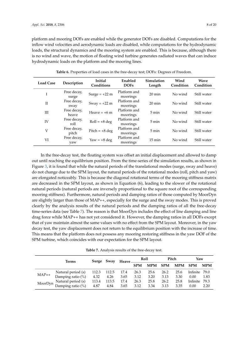