resilient seals tf100 35a
DESCRIPTION
Resilient seals Technical FolderTRANSCRIPT
Resilient Metallic Seals
• Many Cross-Sectional Variations
• Weld Integrity
• High Quality
do not print this page
Eaton’s Aerospace Group offers an extensive variety of standard catalogs featuring metal seals with numerous cross-sections, sizes and shapes adapted for various customer applications. We are able to offer short lead times on a number of prod-ucts, all made to order. Our sales, applications and design engineers are all available to work with you to solve your particular leakage problems in a timely, cost-effective manner, often using exist-ing designs adapted to your needs.
As a preferred supplier, partnering supplier or long-term agreement holder with leading original equipment manufacturers worldwide, Eaton meets or exceeds today’s strict requirements for the supplier approval process, and commits to long-term, value-added rela-tionships with our custom-ers. Our talented employees are committed to supporting your needs in application assistance, design and value engineering, manufacturing, testing, quality assurance and delivery.
1EATON Aerospace TF100-35A November 2010
Table of Contents
Introduction
Introduction to Seals and Seal Types ..................................................2Typical Cavities ...................................................................................3Principles of Metallic Sealing ..............................................................3
Selecting the Correct Seal for Your Application ...................................7
C-Seals™
C-Seal Sketch and Description ............................................................8Standard Part Number Selection ......................................................10Face Type, Internal Pressure C-Seal Tables .......................................12Radial C-Seals ...................................................................................15Face Type, External Pressure C-Seal Tables ......................................16Boss C-Seals .....................................................................................19
E-Seals™
E-Seal Sketch and Description ..........................................................20Standard Part Number Selection ......................................................22Standard Internal Pressure E-Seal Tables ..........................................24Standard External Pressure E-Seal Tables .........................................26High Flex Internal Pressure E-Seal Tables .........................................28High Flex External Pressure E-Seal Tables ........................................30Special 8 E-Seals ..............................................................................32
U-Plex™ Seals
U-Plex Seal Description ....................................................................42High-Flex U-Plex Seal Cross Section ................................................43Standard U-Plex Seal Cross Section Table ........................................44
Microplex Seals
Static Applications ............................................................................45
More Seals
Radial Type Seals ..............................................................................46
More Seal Characteristics, Shapes, and Installation Options ...........47
Appendix
SI Conversion Factors, Glossary of Terms and Abbreviations ...........48
Instructions for Filling in Drawing Forms ..........................................49
2 EATON Aerospace TF100-35A November 2010
Introduction
Introduction to Seals and Seal Types
A seal is a device that prevents the passage, fl ow or leakage of a gas or fl uid. Seals can be divided into two major cate-gories:
1. Static Seals. Sealing takes place between surfaces that have little or no movement relative to one another.
2. Dynamic Seals. Sealing takes place between surfaces that have relative movement, i.e. the movement of a shaft relative to a housing.
There are also seals that fall between these two categories and do not exactly fi t into these basic defi nitions of static or dynamic seals. Some static seals are designed to accom-modate the limited movement of the surfaces being sealed, i.e. due to pressure and/or thermal cycling. These type of seals are sometimes referred to as resilient, quasi- or semi-static seals.
Performance of Mechanical Seals
There are many factors that interact and contribute to seal performance. Seal performance factors include seal geometry, contact force, cavity surface fi nish, sealing medium, pres-sure differentials and operating temperatures.
Truly static seals aim to provide a complete barrier to a potential leakage path; they are zero-leak-age seals (down to 10-11 scc/sec.Helium).
To achieve this, the seal must be resilient enough to conform to cavity irregularities and imper-fections, while remaining rigid enough to provide the required contact force needed to ensure a tight seal. This contact force is a function of the seal cross-sec-tion, as well as the compression of the seal between the mating cavity faces.
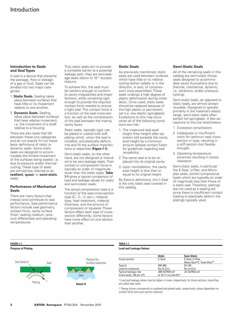
Static seals, typically rigid, can be plated or coated with soft plating which, when the seal is installed, will plastically deform into and fi ll the surface imperfec-tions or asperities (Figure 1-1).
Semi-static seals, on the other hand, are not designed or intend-ed to be zero-leakage seals. Their contact or compression force is typically an order of magnitude lower than the static seals. Table 1-1 gives a typical comparison of load and leakage values for static and semi-static seals.
The actual compression load is a function of the seal cross-section type (C-, E-, U- etc.), material type, heat treatment, material thickness, and the amount of compression or squeeze. These factors affect each type of cross-section differently; some factors have more effect on one section than another.
Static Seals
As previously mentioned, static seals are used between surfaces which have little or no relative cycling (either radially or in the direction, or axis, of compres-sion) once assembled. These seals undergo a high degree of plastic deformation during instal-lation. Once used, static seals should be replaced because of the high plastic or permanent set (i.e. low elastic springback). Exceptions to this may occur when all of the following condi-tions are met:
1. The measured seal axial height (free height) after op-eration still exceeds the cavity axial height by a minimum amount (please contact Eaton for guidelines regarding seal reusability).
2. The same seal is to be re-placed into its original cavity.
3. Upon reinstallation, the cavity axial height is less than or equal to its original height.
By Eaton’s defi nitions, the C-Seal is the only static seal covered in this catalog.
Semi-Static Seals
All of the remaining seals in this catalog are semi-static (those seals designed to accommo-date cavity fl uctuations due to thermal, mechanical, dynamic, i.e. vibrations, and/or pressure cycling).
Semi-static seals, as opposed to static seals, are almost always reusable. Designed to operate primarily in the material’s elastic range, semi-static seals often exhibit full springback. A few ex-ceptions to this are listed below:
1. Excessive compression.
2. Inadequate or insuffi cient room for optimum seal cross-section or type, resulting in a stiff section (not fl exible enough).
3. Operating temperature extremes resulting in stress relaxation.
Semi-static seals, in particular the E-Seal, U-Plex, and Micro-plex seals, exhibit compressive loads which are typically an order of magnitude less than those of a static seal. Therefore, platings are not used as a sealing aid since there is insuffi cient contact loading to plastically deform the platings typically used.
TABLE 1-1
Load and Leakage Values Static Semi-StaticCross-section C-Seal E-Seal, U-Plex, Wave-SeaTMl†, Twist-Flex®†
Typical 250-350 25-150Load-to-compress lbs./in.Circ. lbs./in.Circ.Typical leakage rate .005 SCFM/in.Ø .01 SCFM/in.Ø(room temp, 100 psi ΔP) to 10-11 scc/secHe††
† Load and leakage values may be higher or lower, respectively, for these sections, since they are radial-type seals.
†† Range shown corresponds to unplated and plated seals, respectively; values dependent on surface fi nish and cross-section selected.
FIGURE 1-1
Purpose of Plating
Detail A
Plating FillsSurface Asperities
Cavity
Seal
SealSee Detail A
Plating
3EATON Aerospace TF100-35A November 2010
FIGURE 1-2
Standard Closed
FIGURE 1-3
Standard Open
FIGURE 1-4
Corner Cavity
FIGURE 1-5
Segmented Cavity
Introduction
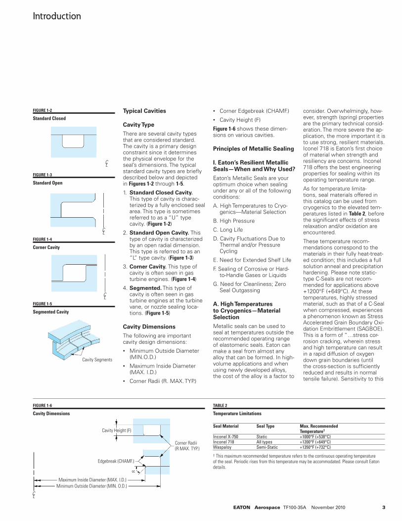
Typical Cavities
Cavity Type
There are several cavity types that are considered standard. The cavity is a primary design constraint since it determines the physical envelope for the seal’s dimensions. The typical standard cavity types are briefl y described below and depicted in Figures 1-2 through 1-5.
1. Standard Closed Cavity. This type of cavity is charac-terized by a fully enclosed seal area. This type is sometimes referred to as a “U” type cavity. (Figure 1-2)
2. Standard Open Cavity. This type of cavity is characterized by an open radial dimension. This type is referred to as an “L” type cavity. (Figure 1-3)
3. Corner Cavity. This type of cavity is often seen in gas turbine engines. (Figure 1-4)
4. Segmented. This type of cavity is often seen in gas turbine engines at the turbine vane, or nozzle sealing loca-tions. (Figure 1-5)
Cavity Dimensions
The following are important cavity design dimensions:• Minimum Outside Diameter
(MIN.O.D.)• Maximum Inside Diameter
(MAX. I.D.)• Corner Radii (R. MAX. TYP.)
• Corner Edgebreak (CHAMF.)• Cavity Height (F)
Figure 1-6 shows these dimen-sions on various cavities.
Principles of Metallic Sealing
I. Eaton’s Resilient Metallic Seals—When and Why Used?
Eaton’s Metallic Seals are your optimum choice when sealing under any or all of the following conditions:
A. High Temperatures to Cryo-genics—Material Selection
B. High Pressure
C. Long Life
D. Cavity Fluctuations Due to Thermal and/or Pressure Cycling
E. Need for Extended Shelf Life
F. Sealing of Corrosive or Hard-to-Handle Gases or Liquids
G. Need for Cleanliness; Zero Seal Outgassing
A. High Temperatures to Cryogenics—Material Selection
Metallic seals can be used to seal at temperatures outside the recommended operating range of elastomeric seals. Eaton can make a seal from almost any alloy that can be formed. In high-volume applications and when using newly developed alloys, the cost of the alloy is a factor to
consider. Overwhelmingly, how-ever, strength (spring) properties are the primary technical consid-eration. The more severe the ap-plication, the more important it is to use strong, resilient materials. Iconel 718 is Eaton’s fi rst choice of material when strength and resiliency are concerns. Inconel 718 offers the best engineering properties for sealing within its operating temperature range.
As for temperature limita-tions, seal materials offered in this catalog can be used from cryogenics to the elevated tem-peratures listed in Table 2, before the signifi cant effects of stress relaxation and/or oxidation are encountered.
These temperature recom-mendations correspond to the materials in their fully heat-treat-ed condition; this includes a full solution anneal and precipitation hardening. Please note static-type C-Seals are not recom-mended for applications above +1200°F (+649°C). At these temperatures, highly stressed material, such as that of a C-Seal when compressed, experiences a phenomenon known as Stress Accelerated Grain Boundary Oxi-dation Embrittlement (SAGBOE). This is a form of “…stress cor-rosion cracking, wherein stress and high temperature can result in a rapid diffusion of oxygen down grain boundaries (until the cross-section is suffi ciently reduced and results in normal tensile failure). Sensitivity to this
Cavity Segments
C L
C L
C L
FIGURE 1-6
Cavity Dimensions
Cavity Height (F)
Edgebreak (CHAMF.)
Corner Radii(R MAX. TYP.)
Maximum Inside Diameter (MAX. I.D.)Minimum Outside Diameter (MIN. O.D.)
C L
8
TABLE 2
Temperature Limitations
Seal Material Seal Type Max. Recommended Temperature† Inconel X-750 Static +1000°F (+538°C)Inconel 718 All types +1200°F (+649°C)Waspaloy Semi-Static +1350°F (+732°C)
† This maximum recommended temperature refers to the continuous operating temperature of the seal. Periodic rises from this temperature may be accommodated. Please consult Eaton details.
4 EATON Aerospace TF100-35A November 2010
Introduction
phenomenon depends on many variables, including alloy chemis-try, processing history, and fi nal heat treatment.”(This defi nition is courtesy of an Inco Alloys International Ins. Paper by D.F. Smith entitled Testing Sensitivity in Low CTE Superalloys dated 3/16/91.)
For semi-static seal applica-tions above +1300°F (+704°C), Eaton is researching and devel-oping manufacturing methods for several new high-tempera-ture superalloys. At this time, Eaton successfully utilizes alloys such as Haynes 188® in operating cycles with a maxi-mum temperature of +1600°F (+871°C). Consult Eaton for any applications with operating tem-peratures greater than +1350°F (+732°C).
B. High Pressure
Eaton’s seals are also designed for high-pressure use. C-Seals have operated successfully at pressures above 200,000 psi, and E-Seals have survived pressure pulsations to 8,000 psi without fretting.
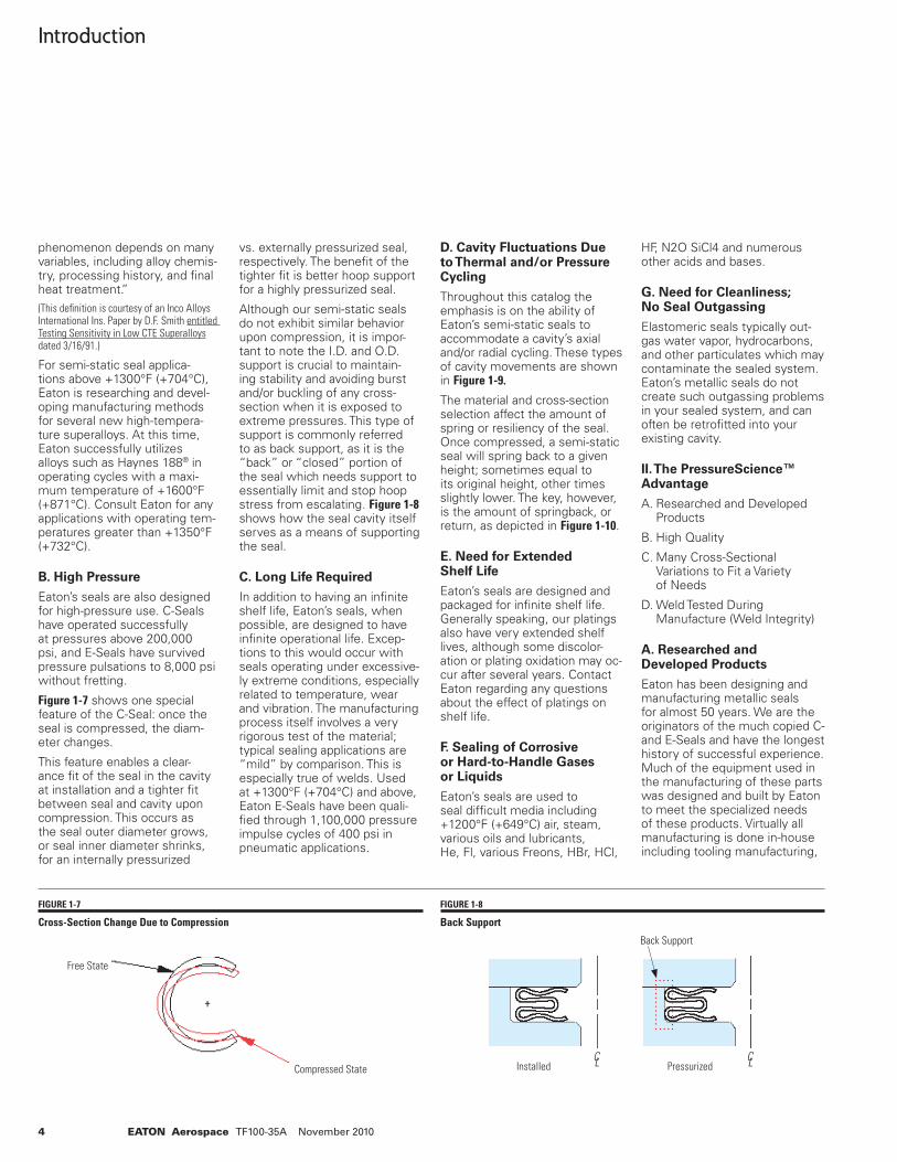
Figure 1-7 shows one special feature of the C-Seal: once the seal is compressed, the diam-eter changes.
This feature enables a clear-ance fi t of the seal in the cavity at installation and a tighter fi t between seal and cavity upon compression. This occurs as the seal outer diameter grows, or seal inner diameter shrinks, for an internally pressurized
vs. externally pressurized seal, respectively. The benefi t of the tighter fi t is better hoop support for a highly pressurized seal.
Although our semi-static seals do not exhibit similar behavior upon compression, it is impor-tant to note the I.D. and O.D. support is crucial to maintain-ing stability and avoiding burst and/or buckling of any cross-section when it is exposed to extreme pressures. This type of support is commonly referred to as back support, as it is the “back” or “closed” portion of the seal which needs support to essentially limit and stop hoop stress from escalating. Figure 1-8 shows how the seal cavity itself serves as a means of supporting the seal.
C. Long Life Required
In addition to having an infi nite shelf life, Eaton’s seals, when possible, are designed to have infi nite operational life. Excep-tions to this would occur with seals operating under excessive-ly extreme conditions, especially related to temperature, wear and vibration. The manufacturing process itself involves a very rigorous test of the material; typical sealing applications are “mild” by comparison. This is especially true of welds. Used at +1300°F (+704°C) and above, Eaton E-Seals have been quali-fi ed through 1,100,000 pressure impulse cycles of 400 psi in pneumatic applications.
D. Cavity Fluctuations Due to Thermal and/or Pressure Cycling
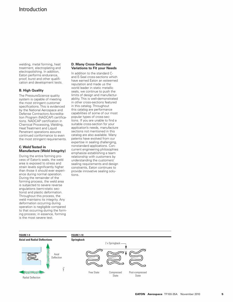
Throughout this catalog the emphasis is on the ability of Eaton’s semi-static seals to accommodate a cavity’s axial and/or radial cycling. These types of cavity movements are shown in Figure 1-9.
The material and cross-section selection affect the amount of spring or resiliency of the seal. Once compressed, a semi-static seal will spring back to a given height; sometimes equal to its original height, other times slightly lower. The key, however, is the amount of springback, or return, as depicted in Figure 1-10.
E. Need for Extended Shelf Life
Eaton’s seals are designed and packaged for infi nite shelf life. Generally speaking, our platings also have very extended shelf lives, although some discolor-ation or plating oxidation may oc-cur after several years. Contact Eaton regarding any questions about the effect of platings on shelf life.
F. Sealing of Corrosive or Hard-to-Handle Gases or Liquids
Eaton’s seals are used to seal diffi cult media including +1200°F (+649°C) air, steam, various oils and lubricants, He, Fl, various Freons, HBr, HCl,
HF, N2O SiCl4 and numerous other acids and bases.
G. Need for Cleanliness; No Seal Outgassing
Elastomeric seals typically out-gas water vapor, hydrocarbons, and other particulates which may contaminate the sealed system. Eaton’s metallic seals do not create such outgassing problems in your sealed system, and can often be retrofi tted into your existing cavity.
II. The PressureScience™ Advantage
A. Researched and Developed Products
B. High Quality
C. Many Cross-Sectional Variations to Fit a Variety of Needs
D. Weld Tested During Manufacture (Weld Integrity)
A. Researched and Developed Products
Eaton has been designing and manufacturing metallic seals for almost 50 years. We are the originators of the much copied C- and E-Seals and have the longest history of successful experience. Much of the equipment used in the manufacturing of these parts was designed and built by Eaton to meet the specialized needs of these products. Virtually all manufacturing is done in-house including tooling manufacturing,
FIGURE 1-7
Cross-Section Change Due to Compression
FIGURE 1-8
Back Support
Free State
Compressed State
Back Support
C L C LInstalled Pressurized
5EATON Aerospace TF100-35A November 2010
Introduction
welding, metal forming, heat treatment, electroplating and electropolishing. In addition, Eaton performs endurance, proof, burst and other qualifi -cation and development tests.
B. High Quality
The PressureScience quality system is capable of meeting the most stringent customer specifi cations. This is evidenced by the National Aerospace and Defense Contractors Accredita-tion Program (NADCAP) certifi ca-tions. NADCAP certifi cation in Chemical Processing, Welding, Heat Treatment and Liquid Penetrant operations assures continued conformance to even the most stringent requirements.
C. Weld Tested in Manufacture (Weld Integrity)
During the entire forming pro-cess of Eaton’s seals, the weld area is exposed to stress and strain levels signifi cantly higher than those it should ever experi-ence during normal operation. During the remainder of the forming process, the weld area is subjected to severe reverse angulations (semi-static sec-tions) and plastic deformation. Throughout this process, the weld maintains its integrity. Any deformation occurring during operation is negligible compared to that occurring during the form-ing process; in essence, forming is the most severe test.
D. Many Cross-Sectional Variations to Fit your Needs
In addition to the standard C- and E-Seal cross-sections which have earned Eaton an esteemed reputation and made us the world leader in static metallic seals, we continue to push the limits of design and manufactur-ability. This is well-demonstrated in other cross-sections featured in this catalog. Throughout this catalog are performance capabilities of some of our most popular types of cross-sec-tions. If you are unable to fi nd a suitable cross-section for your application’s needs, manufacture sections not mentioned in this catalog are also available. Many patents have evolved from our expertise in sealing challenging, nonstandard applications. Con-current engineering philosophies emphasize establishing a team relationship with customers by understanding the customers’ sealing requirements and design constraints, Eaton continues to provide innovative sealing solu-tions.
FIGURE 1-9
Axial and Radial Defl ections
FIGURE 1-10
Springback
C L
Radial Defl ection
AxialDefl ection
Free State
2 x Springback
Compressed State
Post-compressedState
6 EATON Aerospace TF100-35A November 2010
Introduction
TYPE OF SEAL GENERAL COMMENTS AND BASIC FEATURES
C-Seal
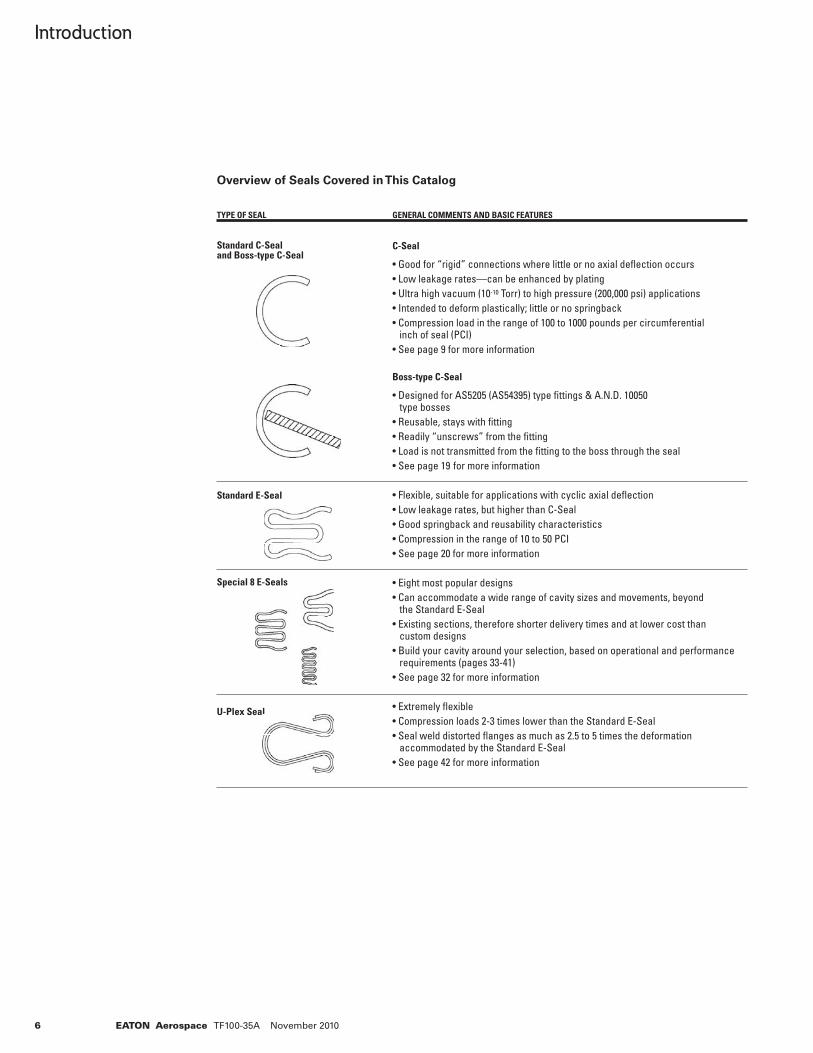
• Good for “rigid” connections where little or no axial defl ection occurs • Low leakage rates—can be enhanced by plating • Ultra high vacuum (10-10 Torr) to high pressure (200,000 psi) applications • Intended to deform plastically; little or no springback • Compression load in the range of 100 to 1000 pounds per circumferential inch of seal (PCI) • See page 9 for more information
Boss-type C-Seal
• Designed for AS5205 (AS54395) type fi ttings & A.N.D. 10050 type bosses • Reusable, stays with fi tting • Readily “unscrews” from the fi tting • Load is not transmitted from the fi tting to the boss through the seal • See page 19 for more information • Flexible, suitable for applications with cyclic axial defl ection • Low leakage rates, but higher than C-Seal • Good springback and reusability characteristics • Compression in the range of 10 to 50 PCI • See page 20 for more information
• Eight most popular designs • Can accommodate a wide range of cavity sizes and movements, beyond the Standard E-Seal • Existing sections, therefore shorter delivery times and at lower cost than custom designs • Build your cavity around your selection, based on operational and performance requirements (pages 33-41) • See page 32 for more information
• Extremely fl exible • Compression loads 2-3 times lower than the Standard E-Seal • Seal weld distorted fl anges as much as 2.5 to 5 times the deformation accommodated by the Standard E-Seal • See page 42 for more information
Overview of Seals Covered in This Catalog
Standard C-Sealand Boss-type C-Seal
Standard E-Seal
Special 8 E-Seals
U-Plex Seal
7EATON Aerospace TF100-35A November 2010
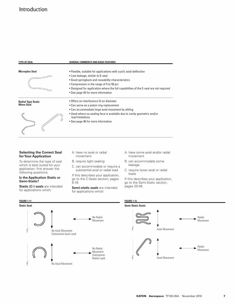
Selecting the Correct Seal for Your Application
To determine the type of seal which is best suited for your application, fi rst answer the following questions:
Is the Application Static or Semi-Static?
Static (C-) seals are intended for applications which:
A. have no axial or radial movement
B. require tight sealing
C. can accommodate or require a substantial axial or radial load
If this describes your application, go to the C-Seals section, pages 8-19.
Semi-static seals are intended for applications which:
A. have some axial and/or radial movement
B. can accommodate some leakage
C. require lower axial or radial loads
If this describes your application, go to the Semi-Static section, pages 20-46.
Introduction
FIGURE 1-11
Static Seal
C L
No RadialMovement
C L
No RadialMovement(SubstantialRadial Load)
No Axial Movement(Substantial Axial Load)
No Axial Movement
FIGURE 1-12
Semi-Static Seals
C L
C L
RadialMovement
RadialMovement
Axial Movement
Axial Movement
TYPE OF SEAL GENERAL COMMENTS AND BASIC FEATURES
• Flexible, suitable for applications with cyclic axial defl ection • Low leakage, similar to E-seal • Good springback and reusability characteristics • Compression in the range of 5 to 50 pci • Designed for application where the full capabilities of the E-seal are not required • See page 45 for more information
• Offers an interference fi t on diameter • Can serve as a piston ring replacement • Can accommodate large axial movement by sliding • Used where no sealing face is available due to cavity geometric and/or load limitations • See page 46 for more information
Radial Type Seals:Wave-Seal
Microplex Seal
8 EATON Aerospace TF100-35A November 2010
C-Seals
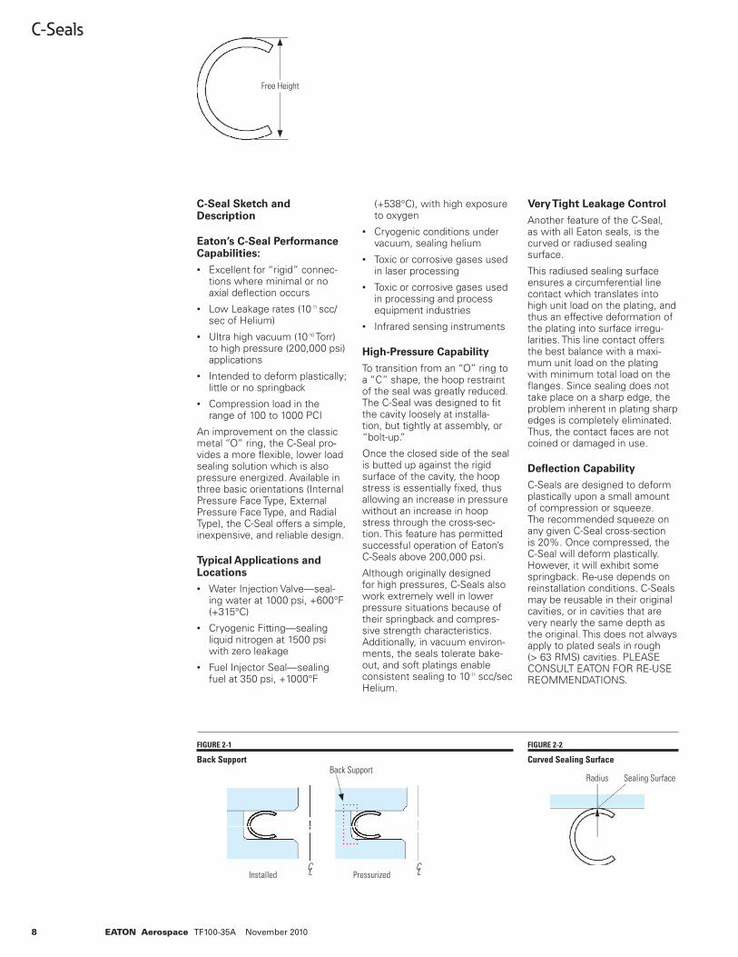
C-Seal Sketch and Description
Eaton’s C-Seal Performance Capabilities:
• Excellent for “rigid” connec-tions where minimal or no axial defl ection occurs
• Low Leakage rates (10-11 scc/sec of Helium)
• Ultra high vacuum (10-10 Torr) to high pressure (200,000 psi) applications
• Intended to deform plastically; little or no springback
• Compression load in the range of 100 to 1000 PCI
An improvement on the classic metal “O” ring, the C-Seal pro-vides a more fl exible, lower load sealing solution which is also pressure energized. Available in three basic orientations (Internal Pressure Face Type, External Pressure Face Type, and Radial Type), the C-Seal offers a simple, inexpensive, and reliable design.
Typical Applications and Locations
• Water Injection Valve—seal-ing water at 1000 psi, +600°F (+315°C)
• Cryogenic Fitting—sealing liquid nitrogen at 1500 psi with zero leakage
• Fuel Injector Seal—sealing fuel at 350 psi, +1000°F
(+538°C), with high exposure to oxygen
• Cryogenic conditions under vacuum, sealing helium
• Toxic or corrosive gases used in laser processing
• Toxic or corrosive gases used in processing and process equipment industries
• Infrared sensing instruments
High-Pressure Capability
To transition from an “O” ring to a “C” shape, the hoop restraint of the seal was greatly reduced. The C-Seal was designed to fi t the cavity loosely at installa-tion, but tightly at assembly, or “bolt-up.”
Once the closed side of the seal is butted up against the rigid surface of the cavity, the hoop stress is essentially fi xed, thus allowing an increase in pressure without an increase in hoop stress through the cross-sec-tion. This feature has permitted successful operation of Eaton’s C-Seals above 200,000 psi.
Although originally designed for high pressures, C-Seals also work extremely well in lower pressure situations because of their springback and compres-sive strength characteristics. Additionally, in vacuum environ-ments, the seals tolerate bake-out, and soft platings enable consistent sealing to 10-11 scc/sec Helium.
Very Tight Leakage Control
Another feature of the C-Seal, as with all Eaton seals, is the curved or radiused sealing surface.
This radiused sealing surface ensures a circumferential line contact which translates into high unit load on the plating, and thus an effective deformation of the plating into surface irregu-larities. This line contact offers the best balance with a maxi-mum unit load on the plating with minimum total load on the fl anges. Since sealing does not take place on a sharp edge, the problem inherent in plating sharp edges is completely eliminated. Thus, the contact faces are not coined or damaged in use.
Defl ection Capability
C-Seals are designed to deform plastically upon a small amount of compression or squeeze. The recommended squeeze on any given C-Seal cross-section is 20%. Once compressed, the C-Seal will deform plastically. However, it will exhibit some springback. Re-use depends on reinstallation conditions. C-Seals may be reusable in their original cavities, or in cavities that are very nearly the same depth as the original. This does not always apply to plated seals in rough (> 63 RMS) cavities. PLEASE CONSULT EATON FOR RE-USE REOMMENDATIONS.
Free Height
FIGURE 2-1
Back Support
FIGURE 2-2
Curved Sealing SurfaceBack Support
C L C LInstalled Pressurized
Radius Sealing Surface
9EATON Aerospace TF100-35A November 2010
C-Seals
Typical load, defl ection, or spring-back capabilities are shown in the Load vs. Defl ection graph on page 11. It is not suggested, however, that the C-Seal be utilized in a cavity exhibiting this amount of continuous cavity cycling during operation. As a rule, a C-Seal will springback 2% of its free height. Repeated reinstallations or continuous cav-ity fl uctuations in excess of this amount could result in failure of the seal through cyclic fatigue and cracking.
Standard C-Seal Part Number Selection
The following pages support a simple part number selection process. Make your selection based on the following criteria:
1. Seal Type and Orientation. Face type, internal or external pressure orientation. Radial type, seal either internal or external pressure, depending on installation orientation.
2. Seal Axial Free Height. Choose a seal size based on cavity dimensions. The seal material thickness and heat treatment may be varied to at-tain different load and defl ec-tion characteristics. Graphs and scaling factors are pro-vided to assist in the proper selection. Also, if a cavity has not yet been defi ned, a cross-section based on desired load and defl ection characteristics can be selected fi rst, then use the diameter tables to design the cavity.
3. Material Thickness and Heat Treat. Cross-sections are offered in standard and thin-ner-than-standard thicknesses for those applications requir-ing reduced load. As for Heat Treatment options, we recom-mend full heat-treatment (so-lution anneal and precipitation hardening). However, NONE may be selected to minimize loadings. Scaling factors for Material Thickness and Heat Treat options are available on page 11.
4. Material Type. The preferred material of choice for strength and load characteristics is Inconel 718.
5. Plating. Select a plating based on maximum operat-ing temperature and leakage control requirements, as well as compatibility with media to be sealed. Details on accept-able temperature limitations and leakage comparisons by plating are provided.
6. Diameter Dash Number. The size of a seal and cavity. Please note, we can also man-ufacture “in-between” sizes, and larger sizes not included in this catalog. Also, not all sizes referenced are kept in stock. Please consult Eaton to check availability or lead time by calling 301-937-4010.
7. Catalog Code. Always desig-nated by a “C.”
10 EATON Aerospace TF100-35A November 2010
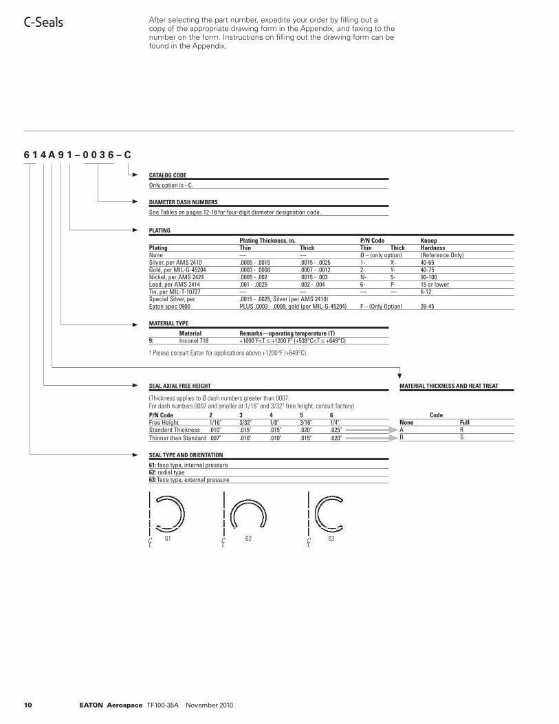
C-Seals After selecting the part number, expedite your order by fi lling out a copy of the appropriate drawing form in the Appendix, and faxing to the number on the form. Instructions on fi lling out the drawing form can be found in the Appendix.
6 1 4 A 9 1 – 0 0 3 6 – C
CATALOG CODE
Only option is –C.
DIAMETER DASH NUMBERS
See Tables on pages 12-18 for four-digit diameter designation code.
MATERIAL TYPE
Material Remarks—operating temperature (T)9: Inconel 718 +1000˚F<T ≤ +1200˚F† (+538°C<T ≤ +649°C)
† Please consult Eaton for applications above +1200°F (+649°C).
SEAL AXIAL FREE HEIGHT
(Thickness applies to Ø dash numbers greater than 0007. For dash numbers 0007 and smaller at 1/16" and 3/32" free height, consult factory)P/N Code 2 3 4 5 6Free Height 1/16" 3/32" 1/8" 3/16" 1/4"Standard Thickness .010" .015" .015" .020" .025"Thinner than Standard .007" .010" .010" .015" .020"
SEAL TYPE AND ORIENTATION
61: face type, internal pressure 62: radial type63: face type, external pressure
61 62 63C L C L C L
PLATING
Plating Thickness, in. P/N Code KnoopPlating Thin Thick Thin Thick HardnessNone — — Ø – (only option) (Reference Only)Silver, per AMS 2410 .0005 - .0015 .0015 - .0025 1- X- 40-65Gold, per MIL-G-45204 .0003 - .0008 .0007 - .0012 2- Y- 40-75Nickel, per AMS 2424 .0005 - .002 .0015 - .003 N- 5- 90-100Lead, per AMS 2414 .001 - .0025 .002 - .004 6- P- 15 or lowerTin, per MIL-T-10727 — — — — 6-12Special Silver, per .0015 - .0025, Silver (per AMS 2410) Eaton spec 0900 PLUS .0003 - .0008, gold (per MIL-G-45204) F – (Only Option) 39-45
MATERIAL THICKNESS AND HEAT TREAT
CodeNone FullA RB S
11EATON Aerospace TF100-35A November 2010
C-Seals
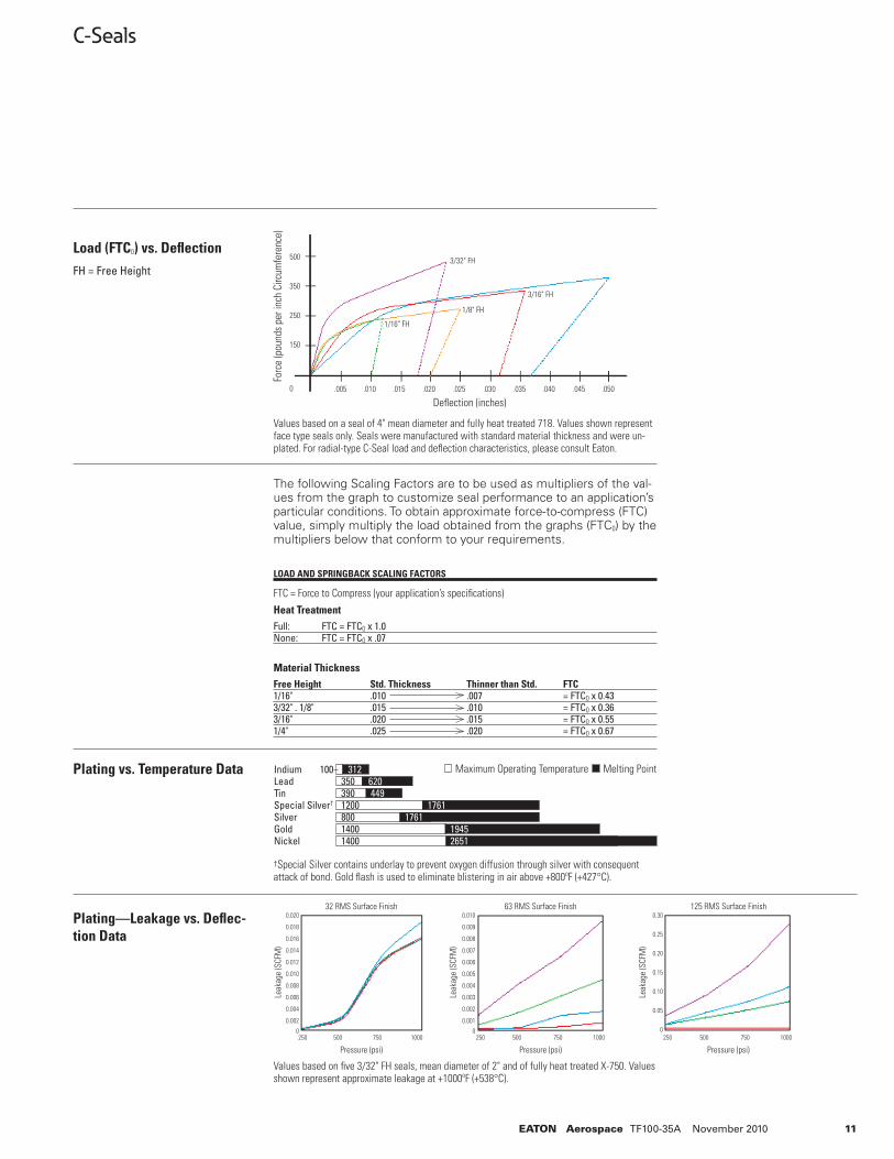
Values based on a seal of 4" mean diameter and fully heat treated 718. Values shown represent face type seals only. Seals were manufactured with standard material thickness and were un-plated. For radial-type C-Seal load and defl ection characteristics, please consult Eaton.
The following Scaling Factors are to be used as multipliers of the val-ues from the graph to customize seal performance to an application’s particular conditions. To obtain approximate force-to-compress (FTC) value, simply multiply the load obtained from the graphs (FTC0) by the multipliers below that conform to your requirements.
LOAD AND SPRINGBACK SCALING FACTORS
FTC = Force to Compress (your application’s specifi cations)
Heat TreatmentFull: FTC = FTC0 x 1.0None: FTC = FTC0 x .07
Material ThicknessFree Height Std. Thickness Thinner than Std. FTC1/16" .010 .007 = FTC0 x 0.433/32" . 1/8" .015 .010 = FTC0 x 0.363/16" .020 .015 = FTC0 x 0.551/4" .025 .020 = FTC0 x 0.67
Load (FTC0) vs. Defl ectionFH = Free Height
Plating vs. Temperature Data
Plating—Leakage vs. Defl ec-tion Data
Indium 312 Lead 350 620 Tin 390 449 Special Silver† 1200 1761 Silver 800 1761 Gold 1400 1945 Nickel 1400 2651
100 Maximum Operating Temperature Melting Point
†Special Silver contains underlay to prevent oxygen diffusion through silver with consequent attack of bond. Gold fl ash is used to eliminate blistering in air above +800ºF (+427°C).
Values based on fi ve 3/32" FH seals, mean diameter of 2" and of fully heat treated X-750. Values shown represent approximate leakage at +1000ºF (+538°C).
1/4" FHFo
rce
(pou
nds
per i
nch
Circ
umfe
renc
e)
Defl ection (inches)
500
350
250
150
0 .005 .010 .015 .020 .025 .030 .035 .040 .045 .050
3/32" FH
3/16" FH
1/8" FH
1/16" FH
Pressure (psi) Pressure (psi) Pressure (psi)
Leak
age
(SCF
M)
Leak
age
(SCF
M)
Leak
age
(SCF
M)
0.020
0.018
0.016
0.014
0.012
0.010
0.008
0.006
0.004
0.002
0
0.010
0.009
0.008
0.007
0.006
0.005
0.004
0.003
0.002
0.001
0
0.30
0.25
0.20
0.15
0.10
0.05
0250 500 750 1000
32 RMS Surface Finish 63 RMS Surface Finish 125 RMS Surface Finish
250 500 750 1000 250 500 750 1000
12 EATON Aerospace TF100-35A November 2010
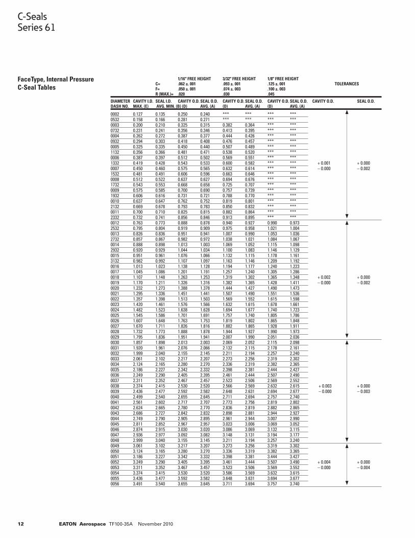
0002 0.127 0.135 0.250 0.240 *** *** *** *** 0532 0.158 0.166 0.281 0.271 *** *** *** ***0003 0.200 0.210 0.325 0.315 0.382 0.364 *** ***0732 0.231 0.241 0.356 0.346 0.413 0.395 *** ***0004 0.262 0.272 0.387 0.377 0.444 0.426 *** ***0932 0.294 0.303 0.418 0.408 0.476 0.457 *** ***0005 0.325 0.335 0.450 0.440 0.507 0.489 *** ***1132 0.356 0.366 0.481 0.471 0.538 0.520 *** ***0006 0.387 0.397 0.512 0.502 0.569 0.551 *** ***1332 0.419 0.428 0.543 0.533 0.600 0.582 *** *** + 0.001 + 0.0000007 0.450 0.460 0.575 0.565 0.632 0.614 *** *** – 0.000 – 0.0021532 0.481 0.491 0.606 0.596 0.663 0.646 *** ***0008 0.512 0.522 0.637 0.627 0.694 0.676 *** ***1732 0.543 0.553 0.668 0.658 0.725 0.707 *** ***0009 0.575 0.585 0.700 0.690 0.757 0.739 *** ***1932 0.606 0.616 0.731 0.721 0.788 0.770 *** ***0010 0.637 0.647 0.762 0.752 0.819 0.801 *** ***2132 0.669 0.678 0.793 0.783 0.850 0.832 *** ***0011 0.700 0.710 0.825 0.815 0.882 0.864 *** ***2332 0.732 0.741 0.856 0.846 0.913 0.895 *** ***0012 0.763 0.773 0.888 0.878 0.940 0.927 0.990 0.9732532 0.795 0.804 0.919 0.909 0.975 0.958 1.021 1.0040013 0.826 0.836 0.951 0.941 1.007 0.990 1.053 1.0362732 0.857 0.867 0.982 0.972 1.038 1.021 1.084 1.0670014 0.888 0.898 1.013 1.003 1.069 1.052 1.115 1.0982932 0.920 0.929 1.044 1.034 1.100 1.083 1.146 1.1290015 0.951 0.961 1.076 1.066 1.132 1.115 1.178 1.1613132 0.982 0.992 1.107 1.097 1.163 1.146 1.209 1.1920016 1.013 1.023 1.138 1.128 1.194 1.177 1.240 1.2230017 1.045 1.086 1.201 1.191 1.257 1.240 1.305 1.2860018 1.107 1.148 1.263 1.253 1.319 1.302 1.365 1.348 + 0.002 + 0.0000019 1.170 1.211 1.326 1.316 1.382 1.365 1.428 1.411 – 0.000 – 0.0020020 1.232 1.273 1.388 1.378 1.444 1.427 1.490 1.4730021 1.295 1.336 1.451 1.441 1.507 1.490 1.551 1.5360022 1.357 1.398 1.513 1.503 1.569 1.552 1.615 1.5980023 1.420 1.461 1.576 1.566 1.632 1.615 1.678 1.6610024 1.482 1.523 1.638 1.628 1.694 1.677 1.740 1.7230025 1.545 1.586 1.701 1.691 1.757 1.740 1.805 1.7860026 1.607 1.648 1.763 1.753 1.819 1.802 1.865 1.8480027 1.670 1.711 1.826 1.816 1.882 1.865 1.928 1.9110028 1.732 1.773 1.888 1.878 1.944 1.927 1.990 1.9730029 1.795 1.836 1.951 1.941 2.007 1.990 2.051 2.0360030 1.857 1.898 2.013 2.003 2.069 2.052 2.115 2.0980031 1.920 1.961 2.076 2.066 2.132 2.115 2.178 2.1610032 1.999 2.040 2.155 2.145 2.211 2.194 2.257 2.2400033 2.061 2.102 2.217 2.207 2.273 2.256 2.319 2.3020034 2.124 2.165 2.280 2.270 2.336 2.319 2.382 2.3650035 2.186 2.227 2.342 2.332 2.398 2.381 2.444 2.4270036 2.249 2.290 2.405 2.395 2.461 2.444 2.507 2.4900037 2.311 2.352 2.467 2.457 2.523 2.506 2.569 2.5520038 2.374 2.415 2.530 2.520 2.566 2.569 2.632 2.615 + 0.003 + 0.0000039 2.436 2.477 2.592 2.582 2.648 2.631 2.694 2.677 – 0.000 – 0.0030040 2.499 2.540 2.655 2.645 2.711 2.694 2.757 2.7400041 2.561 2.602 2.717 2.707 2.773 2.756 2.819 2.8020042 2.624 2.665 2.780 2.770 2.836 2.819 2.882 2.8650043 2.686 2.727 2.842 2.832 2.898 2.881 2.944 2.9270044 2.749 2.790 2.905 2.895 2.961 2.944 3.007 2.990 0045 2.811 2.852 2.967 2.957 3.023 3.006 3.069 3.0520046 2.874 2.915 3.030 3.020 3.086 3.069 3.132 3.1150047 2.936 2.977 3.092 3.082 3.148 3.131 3.194 3.1770048 2.999 3.040 3.155 3.145 3.211 3.194 3.257 3.2400049 3.061 3.102 3.217 3.207 3.273 3.256 3.319 3.3020050 3.124 3.165 3.280 3.270 3.336 3.319 3.382 3.3650051 3.186 3.227 3.342 3.332 3.398 3.381 3.444 3.4270052 3.249 3.290 3.405 3.395 3.461 3.444 3.507 3.490 + 0.004 + 0.0000053 3.311 3.352 3.467 3.457 3.523 3.506 3.569 3.552 – 0.000 – 0.0040054 3.374 3.415 3.530 3.520 3.586 3.569 3.632 3.6150055 3.436 3.477 3.592 3.582 3.648 3.631 3.694 3.6770056 3.491 3.540 3.655 3.645 3.711 3.694 3.757 3.740
1/16" FREE HEIGHT 3/32" FREE HEIGHT 1/8" FREE HEIGHT C= .062 ±. 001 .093 ±. 001 .125 ±. 001 TOLERANCES F= .050 ±. 001 .074 ±. 003 .100 ±. 003 R (MAX.)= .020 .030 .045
DIAMETER CAVITY I.D. SEAL I.D. CAVITY O.D. SEAL O.D. CAVITY O.D. SEAL O.D. CAVITY O.D. SEAL O.D. CAVITY O.D. SEAL O.D.DASH NO. MAX. (E) AVG. MIN. (B) (D) AVG. (A) (D) AVG. (A) (D) AVG. (A)
C-SealsSeries 61
FaceType, Internal Pressure C-Seal Tables
13EATON Aerospace TF100-35A November 2010
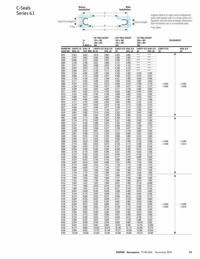
0057 3.561 3.602 3.819 3.802 3.933 3.902 *** ***0058 3.624 3.665 3.882 3.865 3.996 3.965 *** ***0059 3.686 3.727 3.944 3.927 4.058 4.027 *** ***0060 3.749 3.790 4.007 3.990 4.121 4.090 *** ***0061 3.811 3.852 4.069 4.052 4.183 4.152 *** ***0062 3.874 3.915 4.132 4.115 4.246 4.215 *** ***0063 3.936 3.977 4.194 4.177 4.308 4.277 *** ***0064 4.024 4.065 4.282 4.265 4.396 4.365 4.510 4.4650065 4.086 4.127 4.340 4.327 4.458 4.427 4.572 4.5270066 4.149 4.160 4.407 4.390 4.521 4.460 4.653 4.5900067 4.211 4.252 4.469 4.452 4.583 4.552 4.697 4.6520068 4.274 4.315 4.532 4.515 4.646 4.615 4.760 4.715 + 0.004 + 0.0000069 4.336 4.377 4.594 4.577 4.708 4.677 4.822 4.777 – 0.000 – 0.0080070 4.399 4.440 4.657 4.640 4.771 4.740 4.885 4.8400071 4.461 4.502 4.719 4.702 4.833 4.802 4.947 4.9020072 4.524 4.565 4.782 4.765 4.896 4.865 5.010 4.9650073 4.586 4.627 4.844 4.827 4.958 4.927 5.072 5.0270074 4.649 4.690 4.907 4.890 5.021 4.990 5.135 5.0900075 4.711 4.752 4.969 4.952 5.083 5.052 5.197 5.1520076 4.774 4.815 5.032 5.015 5.146 5.115 5.260 5.2150077 4.836 4.877 5.094 5.077 5.208 5.177 5.322 5.2770078 4.899 4.940 5.157 5.140 5.271 5.240 5.385 5.3400079 4.961 5.002 5.219 5.202 5.333 5.302 5.447 5.4020080 5.024 5.065 5.282 5.265 5.396 5.365 5.510 5.4650081 5.086 5.115 5.340 5.327 5.458 5.427 5.572 5.5270082 5.149 5.178 5.407 5.390 5.521 5.490 5.635 5.5900083 5.211 5.240 5.469 5.452 5.583 5.552 5.697 5.6520084 5.274 5.303 5.532 5.515 5.646 5.615 5.760 5.7150085 5.336 5.365 5.594 5.577 5.708 5.677 5.822 5.7770086 5.399 5.428 5.657 5.640 5.771 5.740 5.885 5.8400087 5.461 5.490 5.719 5.702 5.833 5.802 5.947 5.9020088 5.524 5.553 5.782 5.765 5.896 5.865 6.010 5.9650089 5.586 5.615 5.840 5.827 5.958 5.927 6.022 6.0270090 5.649 5.678 5.907 5.890 6.021 5.990 6.135 6.090 + 0.006 + 0.0000092 5.774 5.803 6.032 6.015 6.146 6.115 6.260 6.215 – 0.000 – 0.0120094 5.899 5.928 6.157 6.140 6.271 6.240 6.385 6.3400096 6.024 6.053 6.282 6.265 6.396 6.365 6.510 6.4650098 6.149 6.178 6.407 6.390 6.521 6.490 6.635 6.5900100 6.274 6.303 6.532 6.515 6.646 6.615 6.760 6.7150102 6.399 6.428 6.657 6.640 6.771 6.740 6.885 6.8400104 6.524 6.553 6.782 6.765 6.896 6.865 7.010 6.9650106 6.649 6.678 6.907 6.890 7.021 6.990 7.135 7.0900108 6.774 6.803 7.032 7.015 7.146 7.115 7.260 7.2150110 6.899 6.928 7.157 7.140 7.271 7.240 7.385 7.3400112 7.024 7.053 7.282 7.265 7.396 7.365 7.510 7.4650114 7.149 7.175 7.407 7.390 7.521 7.490 7.635 7.5900116 7.274 7.300 7.532 7.515 7.646 7.615 7.760 7.7150118 7.399 7.425 7.657 7.640 7.771 7.740 7.885 7.8400120 7.524 7.550 7.782 7.765 7.896 7.865 8.010 7.9650122 7.649 7.675 7.907 7.890 8.021 7.990 8.135 8.0900124 7.774 7.800 8.032 8.015 8.146 8.115 8.260 8.2150126 7.899 7.925 8.157 8.140 8.271 8.240 8.385 8.3400128 8.024 8.050 8.282 8.265 8.396 8.365 8.510 8.4650130 8.149 8.175 8.407 8.390 8.521 8.490 8.635 8.5900132 8.274 8.300 8.532 8.515 8.646 8.615 8.760 8.7150134 8.399 8.425 8.657 8.640 8.771 8.740 8.885 8.8400136 8.524 8.550 8.782 8.765 8.891 8.865 9.010 8.9650138 8.649 8.675 8.907 8.890 9.021 8.990 9.135 9.090 + 0.008 + 0.0000140 8.774 8.800 9.032 9.015 9.146 9.115 9.260 9.215 – 0.000 – 0.0160142 8.899 8.925 9.157 9.140 9.271 9.240 9.385 9.3400144 9.024 9.050 9.282 9.265 9.396 9.365 9.510 9.4650146 9.149 9.175 9.407 9.390 9.521 9.490 9.635 9.5900148 9.274 9.300 9.532 9.515 9.646 9.615 9.760 9.7150150 9.399 9.425 9.657 9.640 9.771 9.740 9.885 9.8400152 9.524 9.550 9.782 9.765 9.896 9.865 10.010 9.9650154 9.649 9.675 9.907 9.890 10.021 9.990 10.135 10.0900156 9.774 9.800 10.032 10.015 10.146 10.115 10.260 10.2150158 9.899 9.925 10.157 10.140 10.271 10.240 10.385 10.3400160 10.024 10.050 10.282 10.265 10.396 10.365 10.510 10.465
1/8" FREE HEIGHT 3/16" FREE HEIGHT 1/4" FREE HEIGHT C= .125 ±. 001 .187 ±. 002 .250 ±. 003 TOLERANCES F= .100 ±. 003 .151 ±. 003 .200 ±. 004 R (MAX.)= .045 .070 .090
DIAMETER CAVITY I.D. SEAL I.D. CAVITY O.D. SEAL O.D. CAVITY O.D. SEAL O.D. CAVITY O.D. SEAL O.D. CAVITY O.D. SEAL O.D.DASH NO. MAX. (E) AVG. MIN. (B) (D) AVG. (A) (D) AVG. (A) (D) AVG. (A) (D) (A)
Diagram depicts an open cavity confi guration; seals work equally well in a closed cavity con-fi guration with the same envelope dimensions. Seal dimensions are in un-restrained state.†Free State
DE
B†
A†
Before Installation
After Installation
(Seal Free Height) C† F (Cavity Height)
R Typ.
C-SealsSeries 61
14 EATON Aerospace TF100-35A November 2010
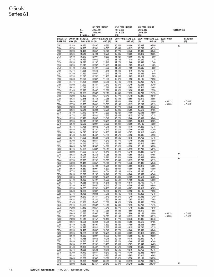
0162 10.149 10.170 10.407 10.390 10.521 10.490 10.635 10.590 0164 10.274 10.295 10.532 10.515 10.646 10.615 10.760 10.715 0166 10.399 10.420 10.657 10.640 10.771 10.740 10.885 10.840 0168 10.524 10.545 10.782 10.765 10.896 10.865 11.010 10.965 0170 10.649 10.670 10.907 10.890 11.021 10.990 11.135 11.090 0172 10.774 10.795 11.032 11.015 11.146 11.115 11.260 11.215 0174 10.899 10.920 11.157 11.140 11.271 11.240 11.385 11.340 0176 11.024 11.045 11.282 11.265 11.396 11.365 11.510 11.465 0178 11.149 11.170 11.407 11.390 11.521 11.490 11.635 11.590 0180 11.274 11.295 11.532 11.515 11.646 11.615 11.760 11.715 0182 11.399 11.420 11.657 11.640 11.771 11.740 11.885 11.840 0184 11.524 11.545 11.782 11.765 11.896 11.865 12.010 11.965 0186 11.649 11.670 11.907 11.890 12.021 11.990 12.135 12.090 0188 11.774 11.795 12.032 12.015 12.146 12.115 12.260 12.215 0190 11.899 11.920 12.157 12.140 12.271 12.240 12.385 12.340 0192 12.024 12.045 12.282 12.265 12.396 12.365 12.510 12.465 0194 12.149 12.170 12.407 12.390 12.521 12.490 12.635 12.590 0196 12.274 12.295 12.532 12.515 12.646 12.615 12.760 12.715 0198 12.399 12.420 12.657 12.640 12.771 12.740 12.885 12.840 0200 12.524 12.545 12.782 12.765 12.896 12.865 13.010 12.965 0202 12.649 12.670 12.907 12.890 13.021 12.990 13.135 13.090 + 0.012 + 0.0000204 12.774 12.795 13.032 13.015 13.146 13.115 13.260 13.215 – 0.000 – 0.0160206 12.899 12.920 13.157 13.140 13.271 13.240 13.385 13.340 0208 13.024 13.045 13.282 13.265 13.396 13.365 13.510 13.465 0210 13.149 13.170 13.407 13.390 13.521 13.490 13.635 13.590 0212 13.274 13.295 13.532 13.515 13.646 13.615 13.760 13.715 0214 13.399 13.420 13.657 13.640 13.771 13.740 13.885 13.840 0216 13.524 13.545 13.782 13.765 13.896 13.865 14.010 13.965 0218 13.649 13.670 13.907 13.890 14.021 13.990 14.135 14.090 0220 13.774 13.795 14.032 14.015 14.146 14.115 14.260 14.215 0222 13.899 13.920 14.157 14.140 14.271 14.240 14.685 14.340 0224 14.024 14.045 14.282 14.265 14.396 14.365 14.510 14.465 0226 14.149 14.170 14.407 14.390 14.521 14.490 14.635 14.590 0228 14.274 14.295 14.532 14.515 14.646 14.615 14.760 14.715 0230 14.399 14.420 14.657 14.640 14.771 14.740 14.885 14.840 0232 14.524 14.545 14.782 14.765 14.896 14.865 15.010 14.965 0234 14.649 14.670 14.907 14.890 15.021 14.990 15.135 15.090 0236 14.774 14.795 15.032 15.015 15.146 15.115 15.260 15.215 0238 14.899 14.920 15.157 15.140 15.271 15.240 15.385 15.340 0240 15.024 15.045 15.282 15.265 15.396 15.365 15.510 15.465 0242 15.149 15.160 15.407 15.390 15.521 15.490 15.635 15.590 0244 15.274 15.285 15.232 15.515 15.646 15.615 15.760 15.715 0246 15.399 15.410 15.657 15.640 15.771 15.740 15.885 15.840 0248 15.524 15.550 15.782 15.765 15.896 15.865 16.010 15.965 0250 15.649 15.660 15.907 15.890 16.021 15.990 16.135 16.090 0252 15.774 15.785 16.032 16.014 16.146 16.114 16.260 16.214 0254 15.899 15.910 16.157 16.140 16.271 16.240 16.385 16.340 0256 16.024 16.035 16.282 16.265 16.396 16.365 16.510 16.465 0258 16.149 16.160 16.407 16.390 16.521 16.490 16.635 16.590 0260 16.274 16.285 16.532 16.515 16.646 16.615 16.760 16.715 0262 16.399 16.410 16.657 16.640 16.771 16.740 16.885 16.840 0264 16.524 16.535 16.782 16.765 16.896 16.865 17.010 16.965 0266 16.649 16.660 16.907 16.890 17.021 16.990 17.135 17.090 0268 16.774 16.785 17.032 17.015 17.146 17.115 17.260 17.215 0270 16.899 16.910 17.157 17.140 17.271 17.240 17.385 17.340 0272 17.024 17.035 17.282 17.265 17.396 17.365 17.510 17.465 0274 17.149 17.160 17.407 17.390 17.521 17.490 17.635 17.590 0276 17.274 17.285 17.532 17.515 17.646 17.615 17.760 17.715 0278 17.399 17.410 17.657 17.640 17.771 17.740 17.885 17.840 0280 17.524 17.535 17.782 17.765 17.896 17.865 18.010 17.965 0282 17.649 17.660 17.907 17.890 18.021 17.990 18.135 18.090 + 0.015 + 0.0000284 17.774 17.785 18.032 18.015 18.146 18.115 18.260 18.215 – 0.000 – 0.0200286 17.899 17.910 18.157 18.140 18.271 18.240 18.385 18.340 0288 18.024 18.035 18.282 18.265 18.396 18.365 18.510 18.465 0290 18.149 18.160 18.407 18.390 18.521 18.490 18.635 18.590 0292 18.274 18.285 18.532 18.515 18.646 18.615 18.760 18.715 0294 18.399 18.410 18.657 18.640 18.771 18.740 18.885 18.840 0296 18.524 18.535 18.782 18.765 18.896 18.865 19.010 18.965 0298 18.649 18.660 18.907 18.890 19.021 18.990 19.135 19.090 0300 18.774 18.785 19.032 19.015 19.146 19.115 19.260 19.215 0302 18.899 18.910 19.157 19.140 19.271 19.240 19.385 19.340 0304 19.024 19.035 19.282 19.265 19.396 19.365 19.540 19.465 0306 19.149 19.160 19.407 19.390 19.521 19.490 19.635 19.590 0308 19.274 19.285 19.532 19.515 19.646 19.615 19.760 19.715 0310 19.399 19.410 19.657 19.640 19.771 19.740 19.885 19.840 0312 19.524 19.535 19.782 19.765 19.896 19.865 20.010 19.965 0314 19.649 19.660 19.907 19.890 20.021 19.990 20.135 20.090 0316 19.774 19.785 20.032 20.015 20.146 20.115 20.260 20.215 0318 19.899 19.910 20.157 20.140 20.271 20.240 20.385 20.340
1/8" FREE HEIGHT 3/16" FREE HEIGHT 1/4" FREE HEIGHT C= .125 ±. 001 .187 ±. 002 .250 ±. 003 TOLERANCES F= .100 ±. 003 .151 ±. 003 .200 ±. 004 R (MAX.)= .045 .070 .090
DIAMETER CAVITY I.D. SEAL I.D. CAVITY O.D. SEAL O.D. CAVITY O.D. SEAL O.D. CAVITY O.D. SEAL O.D. CAVITY O.D. SEAL O.D.DASH NO. MAX. (E) AVG. MIN. (B) (D) AVG. (A) (D) AVG. (A) (D) AVG. (A) (D) (A)
C-SealsSeries 61
15EATON Aerospace TF100-35A November 2010
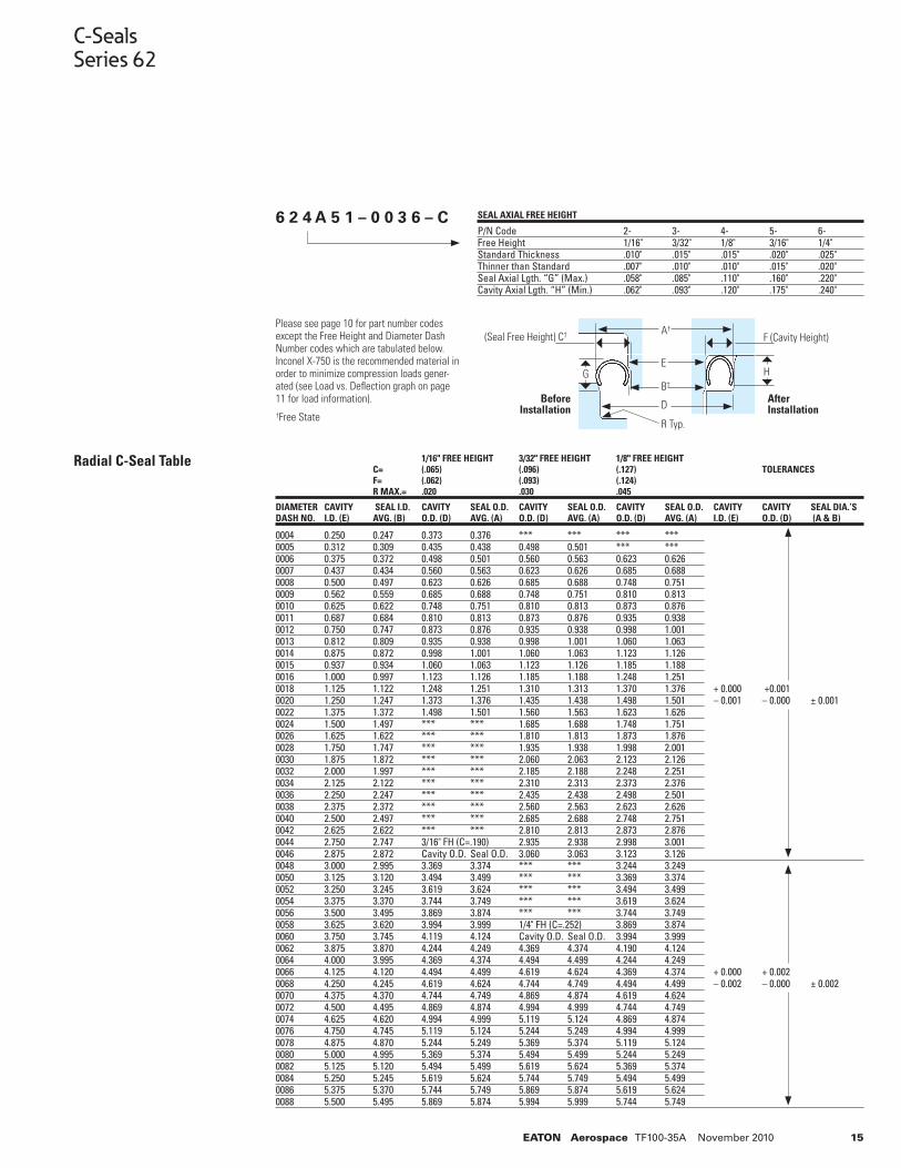
C-SealsSeries 62
0004 0.250 0.247 0.373 0.376 *** *** *** ***0005 0.312 0.309 0.435 0.438 0.498 0.501 *** *** 0006 0.375 0.372 0.498 0.501 0.560 0.563 0.623 0.626 0007 0.437 0.434 0.560 0.563 0.623 0.626 0.685 0.688 0008 0.500 0.497 0.623 0.626 0.685 0.688 0.748 0.751 0009 0.562 0.559 0.685 0.688 0.748 0.751 0.810 0.813 0010 0.625 0.622 0.748 0.751 0.810 0.813 0.873 0.876 0011 0.687 0.684 0.810 0.813 0.873 0.876 0.935 0.938 0012 0.750 0.747 0.873 0.876 0.935 0.938 0.998 1.001 0013 0.812 0.809 0.935 0.938 0.998 1.001 1.060 1.063 0014 0.875 0.872 0.998 1.001 1.060 1.063 1.123 1.126 0015 0.937 0.934 1.060 1.063 1.123 1.126 1.185 1.188 0016 1.000 0.997 1.123 1.126 1.185 1.188 1.248 1.251 0018 1.125 1.122 1.248 1.251 1.310 1.313 1.370 1.376 + 0.000 +0.0010020 1.250 1.247 1.373 1.376 1.435 1.438 1.498 1.501 – 0.001 – 0.000 ± 0.0010022 1.375 1.372 1.498 1.501 1.560 1.563 1.623 1.626 0024 1.500 1.497 *** *** 1.685 1.688 1.748 1.751 0026 1.625 1.622 *** *** 1.810 1.813 1.873 1.876 0028 1.750 1.747 *** *** 1.935 1.938 1.998 2.001 0030 1.875 1.872 *** *** 2.060 2.063 2.123 2.126 0032 2.000 1.997 *** *** 2.185 2.188 2.248 2.251 0034 2.125 2.122 *** *** 2.310 2.313 2.373 2.376 0036 2.250 2.247 *** *** 2.435 2.438 2.498 2.501 0038 2.375 2.372 *** *** 2.560 2.563 2.623 2.626 0040 2.500 2.497 *** *** 2.685 2.688 2.748 2.751 0042 2.625 2.622 *** *** 2.810 2.813 2.873 2.876 0044 2.750 2.747 3/16" FH (C=.190) 2.935 2.938 2.998 3.001 0046 2.875 2.872 Cavity O.D. Seal O.D. 3.060 3.063 3.123 3.126 0048 3.000 2.995 3.369 3.374 *** *** 3.244 3.249 0050 3.125 3.120 3.494 3.499 *** *** 3.369 3.374 0052 3.250 3.245 3.619 3.624 *** *** 3.494 3.499 0054 3.375 3.370 3.744 3.749 *** *** 3.619 3.624 0056 3.500 3.495 3.869 3.874 *** *** 3.744 3.749 0058 3.625 3.620 3.994 3.999 1/4" FH (C=.252) 3.869 3.874 0060 3.750 3.745 4.119 4.124 Cavity O.D. Seal O.D. 3.994 3.999 0062 3.875 3.870 4.244 4.249 4.369 4.374 4.190 4.124 0064 4.000 3.995 4.369 4.374 4.494 4.499 4.244 4.249 0066 4.125 4.120 4.494 4.499 4.619 4.624 4.369 4.374 + 0.000 + 0.0020068 4.250 4.245 4.619 4.624 4.744 4.749 4.494 4.499 – 0.002 – 0.000 ± 0.0020070 4.375 4.370 4.744 4.749 4.869 4.874 4.619 4.624 0072 4.500 4.495 4.869 4.874 4.994 4.999 4.744 4.749 0074 4.625 4.620 4.994 4.999 5.119 5.124 4.869 4.874 0076 4.750 4.745 5.119 5.124 5.244 5.249 4.994 4.999 0078 4.875 4.870 5.244 5.249 5.369 5.374 5.119 5.124 0080 5.000 4.995 5.369 5.374 5.494 5.499 5.244 5.249 0082 5.125 5.120 5.494 5.499 5.619 5.624 5.369 5.374 0084 5.250 5.245 5.619 5.624 5.744 5.749 5.494 5.499 0086 5.375 5.370 5.744 5.749 5.869 5.874 5.619 5.624 0088 5.500 5.495 5.869 5.874 5.994 5.999 5.744 5.749
1/16" FREE HEIGHT 3/32" FREE HEIGHT 1/8" FREE HEIGHT C= (.065) (.096) (.127) TOLERANCES F= (.062) (.093) (.124) R MAX.= .020 .030 .045
DIAMETER CAVITY SEAL I.D. CAVITY SEAL O.D. CAVITY SEAL O.D. CAVITY SEAL O.D. CAVITY CAVITY SEAL DIA.’SDASH NO. I.D. (E) AVG. (B) O.D. (D) AVG. (A) O.D. (D) AVG. (A) O.D. (D) AVG. (A) I.D. (E) O.D. (D) (A & B)
Please see page 10 for part number codes except the Free Height and Diameter Dash Number codes which are tabulated below. Inconel X-750 is the recommended material in order to minimize compression loads gener-ated (see Load vs. Defl ection graph on page 11 for load information).†Free State
Radial C-Seal Table
SEAL AXIAL FREE HEIGHT
P/N Code 2- 3- 4- 5- 6-Free Height 1/16" 3/32" 1/8" 3/16" 1/4"Standard Thickness .010" .015" .015" .020" .025"Thinner than Standard .007" .010" .010" .015" .020"Seal Axial Lgth. “G” (Max.) .058" .085" .110" .160" .220"Cavity Axial Lgth. “H” (Min.) .062" .093" .120" .175" .240"
6 2 4 A 5 1 – 0 0 3 6 – C
A†
E
B†
DBefore Installation
After Installation
G H
R Typ.
F (Cavity Height)(Seal Free Height) C†
16 EATON Aerospace TF100-35A November 2010
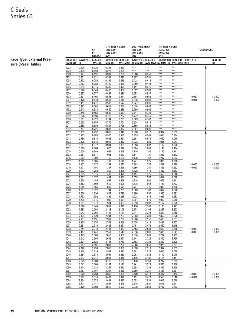
C-SealsSeries 63
Face Type, External Pres-sure C-Seal Tables
0002 0.108 0.128 0.244 0.233 *** *** *** *** 0532 0.139 0.159 0.275 0.264 *** *** *** *** 0003 0.171 0.191 0.307 0.296 0.366 0.351 *** *** 0732 0.201 0.221 0.338 0.327 0.397 0.381 *** *** 0004 0.232 0.252 0.369 0.358 0.428 0.412 *** *** 0932 0.263 0.283 0.400 0.389 0.459 0.443 *** *** 0005 0.295 0.315 0.432 0.421 0.491 0.475 *** *** 1132 0.326 0.346 0.463 0.452 0.522 0.506 *** *** 0006 0.357 0.377 0.494 0.483 0.553 0.537 *** *** 1332 0.391 0.408 0.525 0.514 0.584 0.568 *** *** + 0.000 + 0.0020007 0.420 0.440 0.557 0.546 0.616 0.600 *** *** – 0.001 – 0.0001532 0.451 0.471 0.588 0.577 0.647 0.631 *** *** 0008 0.482 0.502 0.619 0.608 0.678 0.662 *** *** 1732 0.513 0.533 0.650 0.639 0.709 0.693 *** *** 0009 0.545 0.565 0.682 0.671 0.741 0.725 *** ***1932 0.576 0.596 0.713 0.702 0.772 0.756 *** ***0010 0.607 0.627 0.744 0.733 0.803 0.787 *** *** 2132 0.638 0.658 0.775 0.764 0.834 0.818 *** *** 0011 0.669 0.689 0.807 0.796 0.866 0.849 *** *** 2332 0.701 0.721 0.838 0.827 0.897 0.881 *** *** 0012 0.732 0.752 0.869 0.848 0.928 0.912 0.987 0.953 2532 0.763 0.783 0.900 0.889 0.959 0.943 1.018 0.984 0013 0.795 0.815 0.932 0.921 0.991 0.975 1.050 1.016 2732 0.826 0.846 0.963 0.952 1.022 1.006 1.081 1.047 0014 0.857 0.877 0.994 0.983 1.053 1.037 1.112 1.078 2932 0.888 0.908 1.025 1.014 1.084 1.068 1.143 1.104 0015 0.920 0.940 1.057 1.046 1.116 1.100 1.175 1.141 3132 0.951 0.971 1.088 1.077 1.147 1.131 1.203 1.172 0016 0.982 1.002 1.119 1.108 1.178 1.162 1.237 1.2030017 1.045 1.065 1.182 1.171 1.241 1.225 1.300 1.266 0018 1.107 1.127 1.244 1.233 1.303 1.287 1.362 1.328 + 0.000 + 0.0020019 1.171 1.191 1.307 1.296 1.366 1.351 1.426 1.392 – 0.002 – 0.0000020 1.232 1.252 1.369 1.358 1.428 1.412 1.487 1.453 0021 1.295 1.315 1.432 1.421 1.491 1.475 1.550 1.516 0022 1.357 1.377 1.494 1.483 1.553 1.537 1.612 1.578 0023 1.420 1.440 1.557 1.546 1.616 1.600 1.675 1.641 0024 1.482 1.502 1.619 1.608 1.678 1.662 1.737 1.703 0025 1.545 1.565 1.682 1.671 1.741 1.725 1.800 1.766 0026 1.607 1.627 1.744 1.733 1.803 1.787 1.862 1.828 0027 1.670 1.690 1.807 1.796 1.866 1.850 1.925 1.891 0028 1.732 1.752 1.869 1.858 1.928 1.912 1.987 1.953 0029 1.795 1.815 1.932 1.921 1.991 1.975 2.050 2.016 0030 1.857 1.877 1.994 1.983 2.053 2.037 2.112 2.078 0031 1.920 1.940 2.057 2.046 2.116 2.100 2.175 2.1410032 1.983 2.003 2.119 2.108 2.178 2.163 2.237 2.203 0033 2.042 2.066 2.182 2.171 2.241 2.226 2.300 2.266 0034 2.104 2.128 2.244 2.233 2.303 2.288 2.362 2.328 0035 2.167 2.191 2.307 2.296 2.366 2.351 2.425 2.391 0036 2.229 2.253 2.369 2.358 2.428 2.413 2.487 2.453 0037 2.291 2.315 2.432 2.421 2.491 2.476 2.550 2.515 0038 2.354 2.378 2.494 2.483 2.553 2.538 2.612 2.578 + 0.000 + 0.0030039 2.417 2.441 2.557 2.546 2.616 2.601 2.675 2.641 – 0.003 – 0.0000040 2.479 2.503 2.619 2.608 2.678 2.663 2.737 2.703 0041 2.542 2.566 2.682 2.671 2.741 2.726 2.800 2.766 0042 2.604 2.628 2.744 2.733 2.803 2.788 2.862 2.828 0043 2.667 2.691 2.807 2.796 2.866 2.851 2.925 2.891 0044 2.728 2.753 2.869 2.858 2.928 2.913 2.987 2.953 0045 2.778 2.816 2.932 2.921 2.991 2.976 3.050 3.016 0046 2.854 2.878 2.994 2.983 3.053 3.038 3.112 3.078 0047 2.917 2.941 3.057 3.046 3.116 3.101 3.175 3.141 0048 2.979 3.003 3.119 3.108 3.178 3.163 3.237 3.203 0049 3.042 3.066 3.182 3.171 3.241 3.226 3.300 3.266 0050 3.104 3.128 3.244 3.233 3.303 3.288 3.362 3.328 0051 3.167 3.191 3.307 3.296 3.366 3.351 3.425 3.391 0052 3.229 3.253 3.369 3.358 3.428 3.413 3.487 3.453 + 0.000 + 0.0040053 3.292 3.316 3.432 3.421 3.491 3.476 3.550 3.516 – 0.004 – 0.0000054 3.354 3.378 3.494 3.483 3.553 3.538 3.612 3.578 0055 3.417 3.441 3.557 3.546 3.616 3.601 3.675 3.641 0056 3.479 3.503 3.619 3.608 3.678 3.663 3.737 3.703
1/16" FREE HEIGHT 3/32" FREE HEIGHT 1/8" FREE HEIGHT C= .062 ±. 001 .093 ±. 001 .125 ±. 001 TOLERANCES F= .050 ±. 001 .074 ±. 003 .100 ±. 003 R MAX.= .020 .030 .045
DIAMETER CAVITY I.D. SEAL I.D. CAVITY O.D. SEAL O.D. CAVITY O.D. SEAL O.D. CAVITY O.D. SEAL O.D. CAVITY I.D. SEAL I.D.DASH NO. (E) AVG. (B) MIN. (D) AVG. MAX. (A) MIN. (D) AVG. MAX. (A) MIN. (D) AVG. MAX. (A) (E) (B)
17EATON Aerospace TF100-35A November 2010
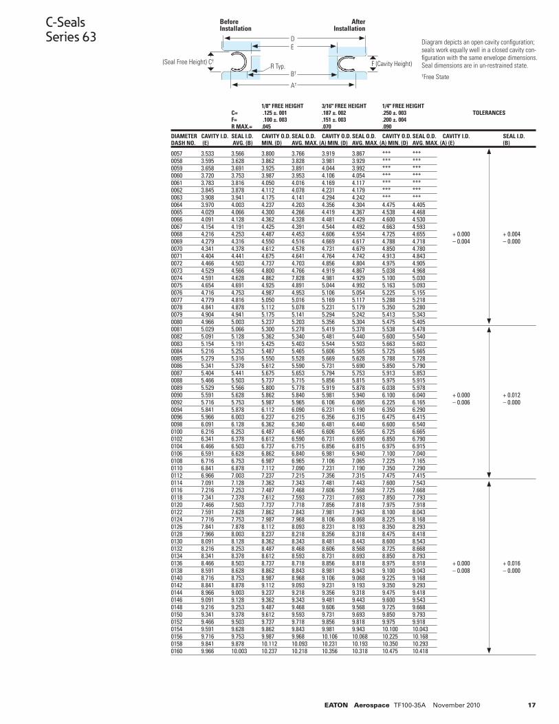
C-SealsSeries 63
0057 3.533 3.566 3.800 3.766 3.919 3.867 *** *** 0058 3.595 3.628 3.862 3.828 3.981 3.929 *** *** 0059 3.658 3.691 3.925 3.891 4.044 3.992 *** *** 0060 3.720 3.753 3.987 3.953 4.106 4.054 *** *** 0061 3.783 3.816 4.050 4.016 4.169 4.117 *** *** 0062 3.845 3.878 4.112 4.078 4.231 4.179 *** *** 0063 3.908 3.941 4.175 4.141 4.294 4.242 *** *** 0064 3.970 4.003 4.237 4.203 4.356 4.304 4.475 4.405 0065 4.029 4.066 4.300 4.266 4.419 4.367 4.538 4.468 0066 4.091 4.128 4.362 4.328 4.481 4.429 4.600 4.530 0067 4.154 4.191 4.425 4.391 4.544 4.492 4.663 4.593 0068 4.216 4.253 4.487 4.453 4.606 4.554 4.725 4.655 + 0.000 + 0.0040069 4.279 4.316 4.550 4.516 4.669 4.617 4.788 4.718 – 0.004 – 0.0000070 4.341 4.378 4.612 4.578 4.731 4.679 4.850 4.780 0071 4.404 4.441 4.675 4.641 4.764 4.742 4.913 4.843 0072 4.466 4.503 4.737 4.703 4.856 4.804 4.975 4.905 0073 4.529 4.566 4.800 4.766 4.919 4.867 5.038 4.968 0074 4.591 4.628 4.862 7.828 4.981 4.929 5.100 5.030 0075 4.654 4.691 4.925 4.891 5.044 4.992 5.163 5.093 0076 4.716 4.753 4.987 4.953 5.106 5.054 5.225 5.155 0077 4.779 4.816 5.050 5.016 5.169 5.117 5.288 5.218 0078 4.841 4.878 5.112 5.078 5.231 5.179 5.350 5.280 0079 4.904 4.941 5.175 5.141 5.294 5.242 5.413 5.343 0080 4.966 5.003 5.237 5.203 5.356 5.304 5.475 5.405 0081 5.029 5.066 5.300 5.278 5.419 5.378 5.538 5.478 0082 5.091 5.128 5.362 5.340 5.481 5.440 5.600 5.540 0083 5.154 5.191 5.425 5.403 5.544 5.503 5.663 5.603 0084 5.216 5.253 5.487 5.465 5.606 5.565 5.725 5.665 0085 5.279 5.316 5.550 5.528 5.669 5.628 5.788 5.7280086 5.341 5.378 5.612 5.590 5.731 5.690 5.850 5.7900087 5.404 5.441 5.675 5.653 5.794 5.753 5.913 5.8530088 5.466 5.503 5.737 5.715 5.856 5.815 5.975 5.915 0089 5.529 5.566 5.800 5.778 5.919 5.878 6.038 5.978 0090 5.591 5.628 5.862 5.840 5.981 5.940 6.100 6.040 + 0.000 + 0.0120092 5.716 5.753 5.987 5.965 6.106 6.065 6.225 6.165 – 0.006 – 0.0000094 5.841 5.878 6.112 6.090 6.231 6.190 6.350 6.290 0096 5.966 6.003 6.237 6.215 6.356 6.315 6.475 6.4150098 6.091 6.128 6.362 6.340 6.481 6.440 6.600 6.5400100 6.216 6.253 6.487 6.465 6.606 6.565 6.725 6.6650102 6.341 6.378 6.612 6.590 6.731 6.690 6.850 6.7900104 6.466 6.503 6.737 6.715 6.856 6.815 6.975 6.915 0106 6.591 6.628 6.862 6.840 6.981 6.940 7.100 7.040 0108 6.716 6.753 6.987 6.965 7.106 7.065 7.225 7.165 0110 6.841 6.878 7.112 7.090 7.231 7.190 7.350 7.290 0112 6.966 7.003 7.237 7.215 7.356 7.315 7.475 7.415 0114 7.091 7.128 7.362 7.343 7.481 7.443 7.600 7.543 0116 7.216 7.253 7.487 7.468 7.606 7.568 7.725 7.668 0118 7.341 7.378 7.612 7.593 7.731 7.693 7.850 7.793 0120 7.466 7.503 7.737 7.718 7.856 7.818 7.975 7.918 0122 7.591 7.628 7.862 7.843 7.981 7.943 8.100 8.043 0124 7.716 7.753 7.987 7.968 8.106 8.068 8.225 8.168 0126 7.841 7.878 8.112 8.093 8.231 8.193 8.350 8.293 0128 7.966 8.003 8.237 8.218 8.356 8.318 8.475 8.418 0130 8.091 8.128 8.362 8.343 8.481 8.443 8.600 8.543 0132 8.216 8.253 8.487 8.468 8.606 8.568 8.725 8.668 0134 8.341 8.378 8.612 8.593 8.731 8.693 8.850 8.793 0136 8.466 8.503 8.737 8.718 8.856 8.818 8.975 8.918 + 0.000 + 0.0160138 8.591 8.628 8.862 8.843 8.981 8.943 9.100 9.043 – 0.008 – 0.0000140 8.716 8.753 8.987 8.968 9.106 9.068 9.225 9.168 0142 8.841 8.878 9.112 9.093 9.231 9.193 9.350 9.293 0144 8.966 9.003 9.237 9.218 9.356 9.318 9.475 9.418 0146 9.091 9.128 9.362 9.343 9.481 9.443 9.600 9.543 0148 9.216 9.253 9.487 9.468 9.606 9.568 9.725 9.668 0150 9.341 9.378 9.612 9.593 9.731 9.693 9.850 9.793 0152 9.466 9.503 9.737 9.718 9.856 9.818 9.975 9.918 0154 9.591 9.628 9.862 9.843 9.981 9.943 10.100 10.043 0156 9.716 9.753 9.987 9.968 10.106 10.068 10.225 10.168 0158 9.841 9.878 10.112 10.093 10.231 10.193 10.350 10.2930160 9.966 10.003 10.237 10.218 10.356 10.318 10.475 10.418
1/8" FREE HEIGHT 3/16" FREE HEIGHT 1/4" FREE HEIGHT C= .125 ±. 001 .187 ±. 002 .250 ±. 003 TOLERANCES F= .100 ±. 003 .151 ±. 003 .200 ±. 004 R MAX.= .045 .070 .090
DIAMETER CAVITY I.D. SEAL I.D. CAVITY O.D. SEAL O.D. CAVITY O.D. SEAL O.D. CAVITY O.D. SEAL O.D. CAVITY I.D. SEAL I.D.DASH NO. (E) AVG. (B) MIN. (D) AVG. MAX. (A) MIN. (D) AVG. MAX. (A) MIN. (D) AVG. MAX. (A) (E) (B)
Diagram depicts an open cavity confi guration; seals work equally well in a closed cavity con-fi guration with the same envelope dimensions. Seal dimensions are in un-restrained state.†Free State
DE
B†
A†
Before Installation
After Installation
(Seal Free Height) C† F (Cavity Height)R Typ.

18 EATON Aerospace TF100-35A November 2010
C-SealsSeries 63
0162 10.091 10.128 10.362 10.348 10.481 10.448 10.600 10.5480164 10.216 10.253 10.487 10.473 10.606 10.573 10.725 10.673 0166 10.341 10.378 10.612 10.598 10.731 10.698 10.850 10.798 0168 10.466 10.503 10.737 10.723 10.856 10.823 10.975 10.923 0170 10.591 10.628 10.862 10.848 10.981 10.948 11.100 11.048 0172 10.716 10.753 10.987 10.973 11.106 11.073 11.225 11.173 0174 10.841 10.878 11.112 11.098 11.231 11.198 11.350 11.298 0176 10.966 11.003 11.237 11.223 11.356 11.323 11.475 11.423 0178 11.091 11.128 11.362 11.348 11.481 11.448 11.600 11.548 0180 11.216 11.253 11.487 11.473 11.606 11.573 11.725 11.673 0182 11.341 11.378 11.612 11.598 11.731 11.698 11.850 11.798 0184 11.466 11.503 11.737 11.723 11.856 11.823 11.975 11.923 0186 11.591 11.628 11.862 11.848 11.981 11.948 12.100 12.048 0188 11.716 11.753 11.987 11.973 12.106 12.073 12.225 12.173 0190 11.841 11.878 12.112 12.098 12.231 12.198 12.350 12.298 0192 11.966 12.003 12.237 12.223 12.356 12.323 12.475 12.423 0194 12.091 12.128 12.362 12.348 12.481 12.448 12.600 12.548 0196 12.216 12.253 12.487 12.473 12.606 12.573 12.725 12.673 0198 12.341 12.378 12.612 12.598 12.731 12.698 12.850 12.798 0200 12.466 12.503 12.737 12.723 12.856 12.823 12.975 12.923 + 0.000 + 0.0160202 12.591 12.628 12.862 12.848 12.981 12.948 13.100 13.048 – 0.012 – 0.0000204 12.716 12.753 12.987 12.973 13.106 13.073 13.225 13.173 0206 12.841 12.878 13.112 13.098 13.231 13.198 13.350 13.298 0208 12.966 13.003 13.237 13.223 13.356 13.323 13.475 13.423 0210 13.091 13.128 13.362 13.348 13.481 13.448 13.600 13.548 0212 13.216 13.253 13.487 13.473 13.606 13.573 13.725 13.673 0214 13.341 13.378 13.612 13.598 13.731 13.698 13.850 13.798 0216 13.466 13.503 13.737 13.723 13.856 13.823 13.975 13.923 0218 13.591 13.628 13.862 13.848 13.981 13.948 14.100 14.048 0220 13.716 13.753 13.987 13.973 14.106 14.073 14.225 14.173 0222 13.841 13.878 14.112 14.098 14.231 14.198 14.350 14.298 0224 13.966 14.003 14.237 14.223 14.356 14.323 14.475 14.423 0226 14.091 14.128 14.362 14.348 14.481 14.448 14.600 14.548 0228 14.216 14.253 14.487 14.473 14.606 14.573 14.725 14.673 0230 14.341 14.378 14.612 14.598 14.731 14.698 14.850 14.798 0232 14.466 14.503 14.737 14.723 14.856 14.823 14.975 14.923 0234 14.591 14.628 14.862 14.848 14.981 14.948 15.100 15.048 0236 14.716 14.753 14.987 14.973 15.106 15.073 15.225 15.173 0238 14.841 14.878 15.112 15.098 15.231 15.198 15.350 15.298 0240 14.966 15.003 15.237 15.223 15.356 15.323 15.475 15.423 0242 15.091 15.128 15.362 15.358 15.481 15.458 15.600 15.558 0244 15.216 15.253 15.487 15.483 15.606 15.583 15.725 15.683 0246 15.341 15.378 15.612 15.608 15.731 15.708 15.850 15.808 0248 15.466 15.503 15.737 15.733 15.856 15.833 15.975 15.933 0250 15.591 15.628 15.862 15.858 15.981 15.958 16.100 16.058 0252 15.716 15.753 15.987 15.983 16.106 16.083 16.225 16.183 0254 15.841 15.878 16.112 16.108 16.231 16.208 16.350 16.308 0256 15.966 16.003 16.237 16.233 16.356 16.333 16.475 16.433 0258 16.091 16.128 16.362 16.358 16.481 16.458 16.600 16.558 0260 16.216 16.253 16.487 16.483 16.606 16.583 16.725 16.683 0262 16.341 16.378 16.612 16.608 16.731 16.708 16.850 16.808 0264 16.466 16.503 16.737 16.733 16.856 16.833 16.975 16.933 0266 16.591 16.628 16.862 16.858 16.981 16.958 17.100 17.058 0268 16.716 16.753 16.987 16.983 17.106 17.083 17.225 17.183 0270 16.841 16.878 17.112 17.108 17.231 17.208 17.350 17.308 0272 16.966 17.003 17.237 17.233 17.356 17.333 17.475 17.433 0274 17.091 17.128 17.362 17.358 17.481 17.458 17.600 17.558 0276 17.216 17.253 17.487 17.483 17.606 17.583 17.725 17.683 0278 17.341 17.378 17.612 17.608 17.731 17.708 17.850 17.808 0280 17.466 17.503 17.737 17.733 17.856 17.833 17.975 17.933 + 0.000 + 0.0200282 17.591 17.628 17.862 17.858 17.981 17.958 18.100 18.058 – 0.015 – 0.0000284 17.716 17.753 17.987 17.983 18.106 18.083 18.225 18.183 0286 17.841 17.878 18.112 18.108 18.231 18.208 18.350 18.308 0288 17.966 18.003 18.237 18.233 18.356 18.333 18.475 18.433 0290 18.091 18.128 18.362 18.358 18.481 18.458 18.600 18.558 0292 18.216 18.253 18.487 18.483 18.606 18.583 18.725 18.683 0294 18.341 18.378 18.612 18.608 18.731 18.708 18.850 18.808 0296 18.460 18.503 18.737 18.733 18.856 18.833 18.975 18.933 0298 18.591 18.628 18.862 18.858 18.981 18.958 19.100 19.058 0300 18.716 18.753 18.987 18.983 19.106 19.083 19.225 19.183 0302 18.841 18.878 19.112 19.108 19.231 19.208 19.350 19.308 0304 18.961 19.003 19.237 19.233 19.356 19.333 19.475 19.433 0306 19.091 19.128 19.362 19.358 19.481 19.458 19.600 19.558 0308 19.216 19.253 19.487 19.483 19.606 19.583 19.725 19.683 0310 19.341 19.378 19.612 19.608 19.731 19.708 19.850 19.808 0312 19.466 19.503 19.737 19.733 19.856 19.833 19.975 19.933 0314 19.591 19.628 19.862 19.858 19.981 19.958 20.100 20.058 0316 19.716 19.753 19.987 19.983 20.106 20.083 20.225 20.183 0318 19.841 19.878 20.112 20.108 20.231 20.208 20.350 20.308
1/8" FREE HEIGHT 3/16" FREE HEIGHT 1/4" FREE HEIGHT C= .125 ±. 001 .187 ±. 002 .250 ±. 003 TOLERANCES F= .100 ±. 003 .074 ±. 003 .200 ±. 004 R MAX.= .045 .070 .090
DIAMETER CAVITY I.D. SEAL I.D. CAVITY O.D. SEAL O.D. CAVITY O.D. SEAL O.D. CAVITY O.D. SEAL O.D. CAVITY I.D. SEAL I.D.DASH NO. (E) AVG. (B) MIN. (D) AVG. MAX. (A) MIN. (D) AVG. MAX. (A) MIN. (D) AVG. MAX. (A) (E) (B)
19EATON Aerospace TF100-35A November 2010
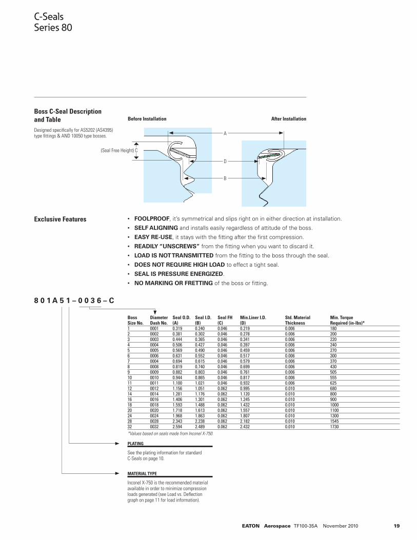
C-SealsSeries 80
Boss C-Seal Description and Table Designed specifi cally for AS5202 (AS4395) type fi ttings & AND 10050 type bosses.
Exclusive Features • FOOLPROOF, it’s symmetrical and slips right on in either direction at installation.
• SELF ALIGNING and installs easily regardless of attitude of the boss.
• EASY RE-USE, it stays with the fi tting after the fi rst compression.
• READILY “UNSCREWS” from the fi tting when you want to discard it.
• LOAD IS NOT TRANSMITTED from the fi tting to the boss through the seal.
• DOES NOT REQUIRE HIGH LOAD to effect a tight seal.
• SEAL IS PRESSURE ENERGIZED.
• NO MARKING OR FRETTING of the boss or fi tting.
PLATING
See the plating information for standard C-Seals on page 10.
MATERIAL TYPE
Inconel X-750 is the recommended material available in order to minimize compression loads generated (see Load vs. Defl ection graph on page 11 for load information).
Boss Diameter Seal O.D. Seal I.D. Seal FH Min.Liner I.D. Std. Material Min. TorqueSize No. Dash No. (A) (B) (C) (D) Thickness Required (in-lbs)*1 0001 0.319 0.240 0.046 0.219 0.006 1802 0002 0.381 0.302 0.046 0.278 0.006 2003 0003 0.444 0.365 0.046 0.341 0.006 2204 0004 0.506 0.427 0.046 0.397 0.006 2405 0005 0.569 0.490 0.046 0.459 0.006 2706 0006 0.631 0.552 0.046 0.517 0.006 3007 0004 0.694 0.615 0.046 0.579 0.006 3708 0008 0.819 0.740 0.046 0.699 0.006 4309 0009 0.882 0.803 0.046 0.761 0.006 50510 0010 0.944 0.865 0.046 0.817 0.006 55511 0011 1.100 1.021 0.046 0.932 0.006 62512 0012 1.156 1.051 0.062 0.995 0.010 68014 0014 1.281 1.176 0.062 1.120 0.010 80016 0016 1.406 1.301 0.062 1.245 0.010 90018 0018 1.593 1.488 0.062 1.432 0.010 100020 0020 1.718 1.613 0.062 1.557 0.010 110024 0024 1.968 1.863 0.062 1.807 0.010 130028 0028 2.343 2.238 0.062 2.182 0.010 154532 0032 2.594 2.489 0.062 2.432 0.010 1730*Values based on seals made from Inconel X-750.
A
D
B
Before Installation
(Seal Free Height) C
After Installation
8 0 1 A 5 1 – 0 0 3 6 – C
20 EATON Aerospace TF100-35A November 2010
Standard E-Seals
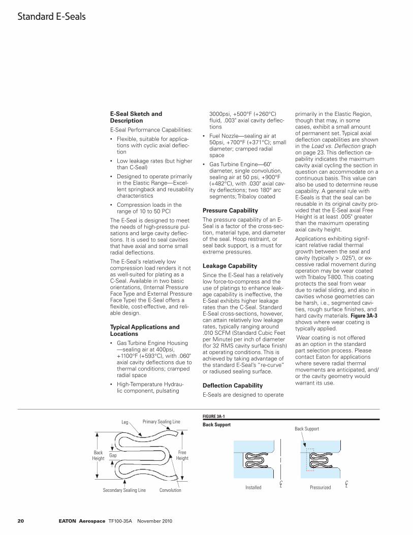
E-Seal Sketch and Description
E-Seal Performance Capabilities:• Flexible, suitable for applica-
tions with cyclic axial defl ec-tion
• Low leakage rates (but higher than C-Seal)
• Designed to operate primarily in the Elastic Range—Excel-lent springback and reusability characteristics
• Compression loads in the range of 10 to 50 PCI
The E-Seal is designed to meet the needs of high-pressure pul-sations and large cavity defl ec-tions. It is used to seal cavities that have axial and some small radial defl ections.
The E-Seal’s relatively low compression load renders it not as well-suited for plating as a C-Seal. Available in two basic orientations, (Internal Pressure Face Type and External Pressure Face Type) the E-Seal offers a fl exible, cost-effective, and reli-able design.
Typical Applications and Locations
• Gas Turbine Engine Housing—sealing air at 400psi, +1100°F (+593°C), with .060" axial cavity defl ections due to thermal conditions; cramped radial space
• High-Temperature Hydrau-lic component, pulsating
3000psi, +500°F (+260°C) fl uid, .003" axial cavity defl ec-tions
• Fuel Nozzle—sealing air at 50psi, +700°F (+371°C); small diameter; cramped radial space
• Gas Turbine Engine—60" diameter, single convolution, sealing air at 50 psi, +900°F (+482°C), with .030" axial cav-ity defl ections; two 180° arc segments; Tribaloy coated
Pressure Capability
The pressure capability of an E-Seal is a factor of the cross-sec-tion, material type, and diameter of the seal. Hoop restraint, or seal back support, is a must for extreme pressures.
Leakage Capability
Since the E-Seal has a relatively low force-to-compress and the use of platings to enhance leak-age capability is ineffective, the E-Seal exhibits higher leakage rates than the C-Seal. Standard E-Seal cross-sections, however, can attain relatively low leakage rates, typically ranging around .010 SCFM (Standard Cubic Feet per Minute) per inch of diameter (for 32 RMS cavity surface fi nish) at operating conditions. This is achieved by taking advantage of the standard E-Seal’s “re-curve” or radiused sealing surface.
Defl ection Capability
E-Seals are designed to operate
primarily in the Elastic Region, though that may, in some cases, exhibit a small amount of permanent set. Typical axial defl ection capabilities are shown in the Load vs. Defl ection graph on page 23. This defl ection ca-pability indicates the maximum cavity axial cycling the section in question can accommodate on a continuous basis. This value can also be used to determine reuse capability. A general rule with E-Seals is that the seal can be reusable in its original cavity pro-vided that the E-Seal axial Free Height is at least .005" greater than the maximum operating axial cavity height.
Applications exhibiting signif-icant relative radial thermal growth between the seal and cavity (typically > .025"), or ex-cessive radial movement during operation may be wear coated with Tribaloy T-800. This coating protects the seal from wear due to radial sliding, and also in cavities whose geometries can be harsh, i.e., segmented cavi-ties, rough surface fi nishes, and hard cavity materials. Figure 3A-3 shows where wear coating is typically applied.
Wear coating is not offered as an option in the standard part selection process. Please contact Eaton for applications where severe radial thermal movements are anticipated, and/or the cavity geometry would warrant its use.
FIGURE 3A-1
Back SupportBack Support
C L C LInstalled Pressurized
Primary Sealing LineLeg
Convolution
Free HeightGapBack
Height
Secondary Sealing Line
21EATON Aerospace TF100-35A November 2010
Standard E-Seals
Standard E-Seal Part Number Selection
The following pages act as a guide through a simple part number selection process. A selection can be based on the following criteria:
1. Seal Type and Orientation. Face type, internal or external pressure, Standard or High Flex Cross-Section
2. Seal Axial Free Height. Choose a seal size best suited to fi t your cavity dimensions. If the cavity has not yet been defi ned, you can select a cross-section based on desired load, defl ection and/or springback characteristics, and then use the diameter tables to design a cavity around your selection.
3. Material Type. As with the Seal Axial Free Height selec-tion, the selection of Material Type will be determined by the maximum operating temperature.
4. Plating. Though plating choices do exist, they do not aid when used on E-Seals due to the E-Seals lower force-to-compress.
5. Diameter Dash Number. This reference is the size of the seal and cavity. Please note, we can also provide “in-between” sizes, as well as larger sizes not included in this catalog. Please note,
not all sizes referenced are in stock. Please consult Eaton at 301-937-4010 to check avail-ability.
6. Catalog Code. Always desig-nated by a “C”.
Semi-Static Seals
The type of cross-section that is best suited for an application is infl uenced by three factors: the cavity geometry, its operational movements, and load and leak-age requirements.
The following questions, once answered, will address selecting the correct type of cross-section:
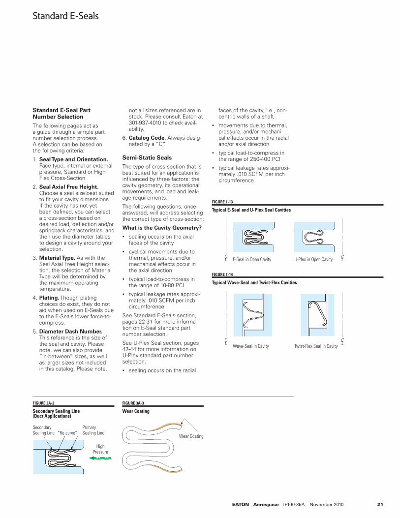
What is the Cavity Geometry?
• sealing occurs on the axial faces of the cavity
• cyclical movements due to thermal, pressure, and/or mechanical effects occur in the axial direction
• typical load-to-compress in the range of 10-80 PCI
• typical leakage rates approxi-mately .010 SCFM per inch circumference
See Standard E-Seals section, pages 22-31 for more informa-tion on E-Seal standard part number selection.
See U-Plex Seal section, pages 42-44 for more information on U-Plex standard part number selection.• sealing occurs on the radial
faces of the cavity, i.e., con-centric walls of a shaft
• movements due to thermal, pressure, and/or mechani-cal effects occur in the radial and/or axial direction
• typical load-to-compress in the range of 250-400 PCI
• typical leakage rates approxi-mately .010 SCFM per inch circumference
FIGURE 3A-2
Secondary Sealing Line (Duct Applications)
FIGURE 3A-3
Wear Coating
“Re-curve”Primary Sealing Line
HighPressure
SecondarySealing Line
Wear Coating
FIGURE 1-13
Typical E-Seal and U-Plex Seal Cavities
FIGURE 1-14
Typical Wave-Seal and Twist-Flex Cavities
C L C LE-Seal in Open Cavity U-Plex in Open Cavity
C L C LWave-Seal in Cavity Twist-Flex Seal in Cavity
22 EATON Aerospace TF100-35A November 2010
Standard E-Seals After selecting your part number, expedite your order by fi lling out a copy of the appropriate drawing form in the attached Appendix and faxing to the number on the form. Instructions on fi lling out the drawing form can also be found in the appendix.
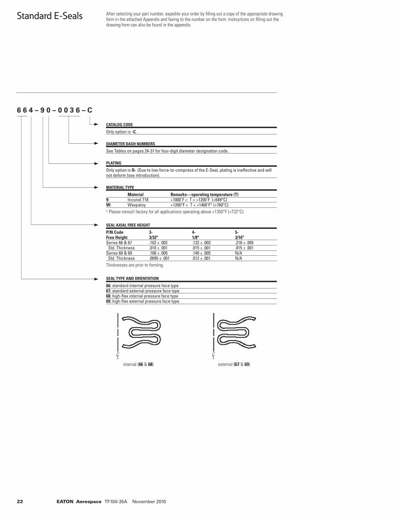
6 6 4 – 9 0 – 0 0 3 6 – C
CATALOG CODE
Only option is -C.
DIAMETER DASH NUMBERS
See Tables on pages 24-31 for four-digit diameter designation code.
PLATING
Only option is O-. (Due to low force-to-compress of the E-Seal, plating is ineffective and will not deform (see introduction).
MATERIAL TYPE
Material Remarks—operating temperature (T)9: Inconel 718 +1000˚F < T < +1200˚F (+649°C) W: Waspaloy +1200°F < T < +1400˚F† (+760°C)† Please consult factory for all applications operating above +1350°F (+732°C).
SEAL AXIAL FREE HEIGHT
P/N Code 3- 4- 5-Free Height 3/32" 1/8" 3/16"Series 66 & 67 .102 ± .002 .132 ± .003 .218 ± .005 Std. Thickness .010 ± .001 .015 ± .001 .015 ± .001Series 68 & 69 .108 ± .005 .140 ± .005 N/A Std. Thickness .0095 ± .001 .012 ± .001 N/AThicknesses are prior to forming.
SEAL TYPE AND ORIENTATION
66: standard internal pressure face type67: standard external pressure face type68: high-fl ex internal pressure face type69: high-fl ex external pressure face type
internal (66 & 68) external (67 & 69)
C L C L
23EATON Aerospace TF100-35A November 2010
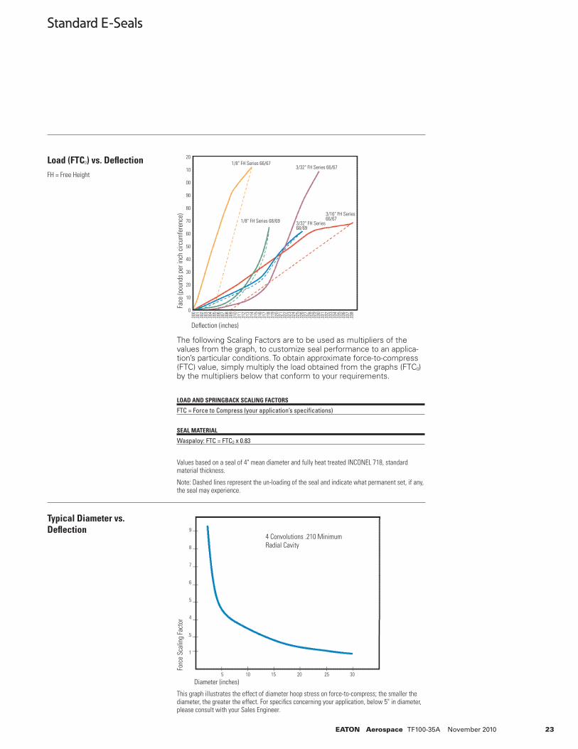
Load (FTC0) vs. Defl ectionFH = Free Height
Typical Diameter vs. Defl ection
Standard E-Seals
The following Scaling Factors are to be used as multipliers of the values from the graph, to customize seal performance to an applica-tion’s particular conditions. To obtain approximate force-to-compress (FTC) value, simply multiply the load obtained from the graphs (FTC0) by the multipliers below that conform to your requirements.
LOAD AND SPRINGBACK SCALING FACTORS
FTC = Force to Compress (your application’s specifi cations)
SEAL MATERIAL
Waspaloy: FTC = FTC0 x 0.83
Values based on a seal of 4" mean diameter and fully heat treated INCONEL 718, standard material thickness.
Note: Dashed lines represent the un-loading of the seal and indicate what permanent set, if any, the seal may experience.
This graph illustrates the effect of diameter hoop stress on force-to-compress; the smaller the diameter, the greater the effect. For specifi cs concerning your application, below 5" in diameter, please consult with your Sales Engineer.
Face
(pou
nds
per i
nch
circ
umfe
renc
e)
Defl ection (inches)
Forc
e Sc
alin
g Fa
ctor
Diameter (inches)
20
10
00
90
80
70
60
50
40
30
20
10
0
.000
.001
.002
.003
.004
.005
.006
.007
.008
.009
.010
.011
.012
.013
.014
.015
.016
.017
.018
.019
.020
.021
.022
.023
.024
.025
.026
.027
.028
.029
.030
.031
.032
.033
.034
.035
.036
.037
.038
4 Convolutions .210 MinimumRadial Cavity
9
8
7
6
5
4
.5
1
5 10 15 20 25 30
1/8" FH Series 66/673/32" FH Series 66/67
1/8" FH Series 68/69 3/32" FH Series 68/69
3/16" FH Series 66/67
24 EATON Aerospace TF100-35A November 2010
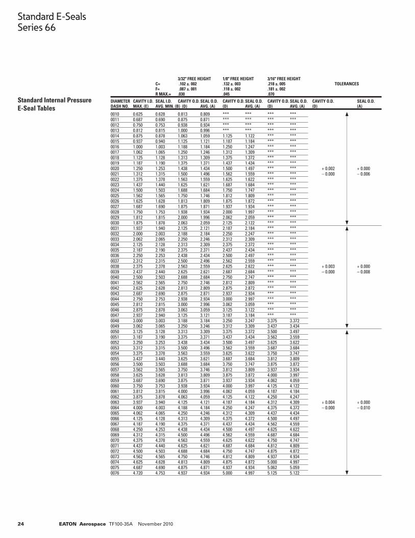
Standard E-SealsSeries 66
Standard Internal Pressure E-Seal Tables
0010 0.625 0.628 0.813 0.809 *** *** *** ***0011 0.687 0.690 0.875 0.871 *** *** *** ***0012 0.750 0.753 0.938 0.934 *** *** *** ***0013 0.812 0.815 1.000 0.996 *** *** *** ***0014 0.875 0.878 1.063 1.059 1.125 1.122 *** ***0015 0.937 0.940 1.125 1.121 1.187 1.184 *** ***0016 1.000 1.003 1.188 1.184 1.250 1.247 *** ***0017 1.062 1.065 1.250 1.246 1.312 1.309 *** ***0018 1.125 1.128 1.313 1.309 1.375 1.372 *** ***0019 1.187 1.190 1.375 1.371 1.437 1.434 *** ***0020 1.250 1.253 1.438 1.434 1.500 1.497 *** *** + 0.002 + 0.0000021 1.312 1.315 1.500 1.496 1.562 1.559 *** *** – 0.000 – 0.0060022 1.375 1.378 1.563 1.559 1.625 1.622 *** ***0023 1.437 1.440 1.625 1.621 1.687 1.684 *** ***0024 1.500 1.503 1.688 1.684 1.750 1.747 *** ***0025 1.562 1.565 1.750 1.746 1.812 1.809 *** ***0026 1.625 1.628 1.813 1.809 1.875 1.872 *** ***0027 1.687 1.690 1.875 1.871 1.937 1.934 *** ***0028 1.750 1.753 1.938 1.934 2.000 1.997 *** ***0029 1.812 1.815 2.000 1.996 2.062 2.059 *** ***0030 1.875 1.878 2.063 2.059 2.125 2.122 *** ***0031 1.937 1.940 2.125 2.121 2.187 2.184 *** ***0032 2.000 2.003 2.188 2.184 2.250 2.247 *** ***0033 2.062 2.065 2.250 2.246 2.312 2.309 *** ***0034 2.125 2.128 2.313 2.309 2.375 2.372 *** ***0035 2.187 2.190 2.375 2.371 2.437 2.434 *** ***0036 2.250 2.253 2.438 2.434 2.500 2.497 *** ***0037 2.312 2.315 2.500 2.496 2.562 2.559 *** ***0038 2.375 2.378 2.563 2.559 2.625 2.622 *** *** + 0.003 + 0.0000039 2.437 2.440 2.625 2.621 2.687 2.684 *** *** – 0.000 – 0.0080040 2.500 2.503 2.688 2.684 2.750 2.747 *** ***0041 2.562 2.565 2.750 2.746 2.812 2.809 *** ***0042 2.625 2.628 2.813 2.809 2.875 2.872 *** ***0043 2.687 2.690 2.875 2.871 2.937 2.934 *** ***0044 2.750 2.753 2.938 2.934 3.000 2.997 *** ***0045 2.812 2.815 3.000 2.996 3.062 3.059 *** ***0046 2.875 2.878 3.063 3.059 3.125 3.122 *** ***0047 2.937 2.940 3.125 3.121 3.187 3.184 *** ***0048 3.000 3.003 3.188 3.184 3.250 3.247 3.375 3.3720049 3.062 3.065 3.250 3.246 3.312 3.309 3.437 3.4340050 3.125 3.128 3.313 3.309 3.375 3.372 3.500 3.4970051 3.187 3.190 3.375 3.371 3.437 3.434 3.562 3.5590052 3.250 3.253 3.438 3.434 3.500 3.497 3.625 3.6220053 3.312 3.315 3.500 3.496 3.562 3.559 3.687 3.6840054 3.375 3.378 3.563 3.559 3.625 3.622 3.750 3.7470055 3.437 3.440 3.625 3.621 3.687 3.684 3.812 3.8090056 3.500 3.503 3.688 3.684 3.750 3.747 3.875 3.8720057 3.562 3.565 3.750 3.746 3.812 3.809 3.937 3.9340058 3.625 3.628 3.813 3.809 3.875 3.872 4.000 3.9970059 3.687 3.690 3.875 3.871 3.937 3.934 4.062 4.0590060 3.750 3.753 3.938 3.934 4.000 3.997 4.125 4.1220061 3.812 3.815 4.000 3.996 4.062 4.059 4.187 4.1840062 3.875 3.878 4.063 4.059 4.125 4.122 4.250 4.2470063 3.937 3.940 4.125 4.121 4.187 4.184 4.312 4.309 + 0.004 + 0.0000064 4.000 4.003 4.188 4.184 4.250 4.247 4.375 4.372 – 0.000 – 0.0100065 4.062 4.065 4.250 4.246 4.312 4.309 4.437 4.4340066 4.125 4.128 4.313 4.309 4.375 4.372 4.500 4.4970067 4.187 4.190 4.375 4.371 4.437 4.434 4.562 4.5590068 4.250 4.253 4.438 4.434 4.500 4.497 4.625 4.6220069 4.312 4.315 4.500 4.496 4.562 4.559 4.687 4.6840070 4.375 4.378 4.563 4.559 4.625 4.622 4.750 4.7470071 4.437 4.440 4.625 4.621 4.687 4.684 4.812 4.8090072 4.500 4.503 4.688 4.684 4.750 4.747 4.875 4.8720073 4.562 4.565 4.750 4.746 4.812 4.809 4.937 4.9340074 4.625 4.628 4.813 4.809 4.875 4.872 5.000 4.9970075 4.687 4.690 4.875 4.871 4.937 4.934 5.062 5.0590076 4.720 4.753 4.937 4.934 5.000 4.997 5.125 5.122
3/32" FREE HEIGHT 1/8" FREE HEIGHT 3/16" FREE HEIGHT C= .102 ±. 002 .132 ±. 003 .218 ±. 005 TOLERANCES F= .087 ±. 001 .118 ±. 002 .181 ±. 002 R MAX.= .030 .045 .070
DIAMETER CAVITY I.D. SEAL I.D. CAVITY O.D. SEAL O.D. CAVITY O.D. SEAL O.D. CAVITY O.D. SEAL O.D. CAVITY O.D. SEAL O.D.DASH NO. MAX. (E) AVG. MIN. (B) (D) AVG. (A) (D) AVG. (A) (D) AVG. (A) (D) (A)
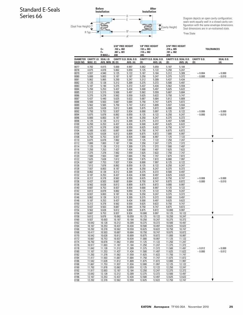
25EATON Aerospace TF100-35A November 2010
Standard E-SealsSeries 66
0077 4.782 4.815 5.000 4.997 5.062 5.059 5.187 5.1840078 4.875 4.878 5.062 5.059 5.125 5.122 5.250 5.247 0079 4.937 4.940 5.125 5.122 5.187 5.184 5.312 5.309 + 0.004 + 0.0000080 5.000 5.003 5.187 5.187 5.250 5.247 5.375 5.372 – 0.000 – 0.0100081 5.062 5.065 5.250 5.247 5.312 5.309 5.437 5.434 0082 5.125 5.128 5.312 5.309 5.375 5.372 5.500 5.497 0083 5.187 5.190 5.375 5.372 5.437 5.434 5.562 5.559 0084 5.250 5.253 5.437 5.434 5.500 5.497 5.625 5.622 0085 5.312 5.315 5.500 5.497 5.562 5.559 5.687 5.684 0086 5.375 5.378 5.562 5.559 5.625 5.622 5.750 5.747 0087 5.437 5.440 5.625 5.622 5.687 5.684 5.812 5.809 0088 5.500 5.503 5.687 5.684 5.750 5.747 5.875 5.872 0089 5.562 5.565 5.750 5.747 5.812 5.809 5.937 5.934 0090 5.625 5.628 5.812 5.809 5.875 5.872 6.000 5.997 0092 5.750 5.753 5.937 5.934 6.000 5.997 6.125 6.122 + 0.006 + 0.0000094 5.875 5.878 6.062 6.059 6.125 6.122 6.250 6.247 – 0.000 – 0.0100096 6.000 6.003 6.187 6.184 6.250 6.247 6.375 6.3720098 6.125 6.128 6.312 6.309 6.375 6.372 6.497 6.500 0100 6.250 6.253 6.437 6.434 6.500 6.497 6.625 6.622 0102 6.375 6.378 6.562 6.559 6.625 6.622 6.750 6.747 0104 6.500 6.503 6.687 6.684 6.750 6.747 6.875 6.872 0106 6.625 6.628 6.812 6.809 6.875 6.872 7.000 6.997 0108 6.750 6.753 6.937 6.934 7.000 6.997 7.125 7.122 0110 6.875 6.878 7.062 7.059 7.125 7.122 7.250 7.247 0112 7.000 7.003 7.187 7.184 7.250 7.247 7.375 7.372 0114 7.125 7.128 7.312 7.309 7.375 7.372 7.500 7.497 0116 7.250 7.253 7.437 7.434 7.500 7.497 7.625 7.622 0118 7.375 7.378 7.562 7.559 7.625 7.622 7.750 7.747 0120 7.500 7.503 7.687 7.684 7.750 7.747 7.875 7.872 0122 7.625 7.628 7.812 7.809 7.875 7.872 8.000 7.997 0124 7.687 7.753 7.937 7.934 8.000 7.997 8.125 8.122 0126 7.812 7.878 8.062 8.059 8.125 8.122 8.250 8.247 0128 7.937 8.003 8.187 8.184 8.250 8.247 8.375 8.372 0130 8.062 8.128 8.312 8.309 8.375 8.372 8.500 8.497 0132 8.187 8.253 8.437 8.434 8.500 8.497 8.625 8.622 0134 8.312 8.378 8.562 8.559 8.625 8.622 8.750 8.747 + 0.008 + 0.0000136 8.437 8.503 8.687 8.684 8.750 8.747 8.875 8.872 – 0.000 – 0.0100138 8.562 8.628 8.812 8.809 8.875 8.872 9.000 8.997 0140 8.687 8.753 8.937 8.934 9.000 8.997 9.125 9.122 0142 8.812 8.878 9.062 9.059 9.125 9.122 9.250 9.247 0144 8.937 9.003 9.187 9.184 9.250 9.247 9.375 9.372 0146 9.062 9.128 9.312 9.309 9.375 9.372 9.500 9.497 0148 9.187 9.253 9.437 9.434 9.500 9.497 9.625 9.622 0150 9.312 9.378 9.562 9.559 9.625 9.622 9.750 9.747 0152 9.437 9.503 9.687 9.684 9.750 9.747 9.875 9.872 0154 9.562 9.628 9.812 9.809 9.875 9.872 10.000 9.9970156 9.687 9.753 9.937 9.934 10.000 9.997 10.125 10.1220158 9.812 9.878 10.062 10.059 10.125 10.122 10.250 10.2470160 9.937 10.003 10.187 10.184 10.250 10.247 10.375 10.3720162 10.042 10.128 10.312 10.309 10.375 10.372 10.500 10.4970164 10.167 10.253 10.437 10.434 10.500 10.497 10.625 10.6220166 10.292 10.378 10.562 10.559 10.625 10.622 10.750 10.7470168 10.417 10.503 10.687 10.684 10.750 10.747 10.875 10.8720170 10.542 10.628 10.812 10.809 10.875 10.872 11.000 10.9970172 10.667 10.753 10.937 10.934 11.000 10.997 11.125 11.1220174 10.792 10.878 11.062 11.059 11.125 11.122 11.250 11.2470176 10.917 11.003 11.187 11.184 11.250 11.247 11.375 11.3720178 11.042 11.128 11.312 11.309 11.375 11.372 11.500 11.497 + 0.012 + 0.0000180 11.167 11.253 11.437 11.434 11.500 11.497 11.625 11.622 – 0.000 – 0.0120182 11.292 11.378 11.562 11.559 11.625 11.622 11.750 11.7470184 11.417 11.503 11.687 11.684 11.750 11.747 11.875 11.8720186 11.542 11.628 11.812 11.809 11.875 11.872 12.000 11.9970188 11.667 11.753 11.937 11.934 12.000 11.997 12.125 12.122 0190 11.792 11.878 12.062 12.059 12.125 12.122 12.250 12.247 0192 11.917 12.003 12.187 12.184 12.250 12.247 12.375 12.3720194 12.042 12.128 12.312 12.309 12.375 12.372 12.500 12.4970196 12.167 12.253 12.437 12.434 12.500 12.497 12.625 12.6220198 12.292 12.378 12.562 12.559 12.625 12.622 12.750 12.747
3/32" FREE HEIGHT 1/8" FREE HEIGHT 3/16" FREE HEIGHT C= .102 ±. 002 .132 ±. 003 .218 ±. 005 TOLERANCES F= .087 ±. 001 .118 ±. 002 .181 ±. 002 R MAX.= .030 .045 .070
DIAMETER CAVITY I.D. SEAL I.D. CAVITY O.D. SEAL O.D. CAVITY O.D. SEAL O.D. CAVITY O.D. SEAL O.D. CAVITY O.D. SEAL O.D.DASH NO. MAX. (E) AVG. MIN. (B) (D) AVG. (A) (D) AVG. (A) (D) AVG. (A) (D) (A)
Diagram depicts an open cavity confi guration; seals work equally well in a closed cavity con-fi guration with the same envelope dimensions. Seal dimensions are in un-restrained state.†Free State
DE
B†
A†
Before Installation
After Installation
(Seal Free Height) C† F (Cavity Height)
R Typ.
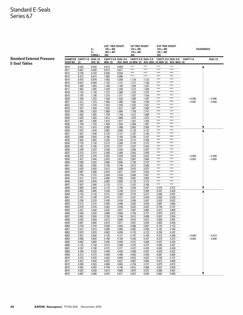
26 EATON Aerospace TF100-35A November 2010
Standard E-SealsSeries 67
Standard External Pressure E-Seal Tables
0010 0.625 0.628 0.813 0.809 *** *** *** ***0011 0.687 0.690 0.875 0.871 *** *** *** ***0012 0.750 0.753 0.938 0.934 *** *** *** ***0013 0.812 0.815 1.000 0.996 *** *** *** ***0014 0.875 0.878 1.063 1.059 1.125 1.122 *** ***0015 0.937 0.940 1.155 1.121 1.217 1.184 *** *** 0016 1.000 1.003 1.188 1.184 1.250 1.247 *** ***0017 1.062 1.065 1.250 1.246 1.312 1.309 *** ***0018 1.125 1.128 1.313 1.309 1.375 1.372 *** ***0019 1.187 1.190 1.375 1.371 1.437 1.434 *** ***0020 1.250 1.253 1.438 1.434 1.500 1.497 *** *** + 0.000 + 0.006 0021 1.312 1.315 1.500 1.496 1.562 1.559 *** *** – 0.002 – 0.000 0022 1.375 1.378 1.563 1.559 1.625 1.622 *** ***0023 1.437 1.440 1.625 1.621 1.687 1.684 *** ***0024 1.500 1.503 1.688 1.684 1.750 1.747 *** ***0025 1.562 1.565 1.750 1.746 1.812 1.809 *** ***0026 1.625 1.628 1.813 1.809 1.875 1.872 *** ***0027 1.687 1.690 1.875 1.871 1.937 1.934 *** ***0028 1.750 1.753 1.938 1.934 2.000 1.997 *** ***0029 1.812 1.815 2.000 1.996 2.062 2.059 *** ***0030 1.875 1.878 2.063 2.059 2.125 2.122 *** ***0031 1.937 1.940 2.125 2.121 2.187 2.184 *** ***0032 2.000 2.003 2.188 2.184 2.250 2.247 *** *** 0033 2.062 2.065 2.250 2.246 2.312 2.309 *** ***0034 2.125 2.128 2.313 2.309 2.375 2.372 *** ***0035 2.187 2.190 2.375 2.371 2.437 2.434 *** ***0036 2.250 2.253 2.438 2.434 2.500 2.497 *** ***0037 2.312 2.315 2.500 2.496 2.562 2.559 *** ***0038 2.375 2.378 2.563 2.559 2.625 2.622 *** *** + 0.000 + 0.008 0039 2.437 2.440 2.625 2.621 2.687 2.684 *** *** – 0.003 – 0.000 0040 2.500 2.503 2.688 2.684 2.750 2.747 *** ***0041 2.562 2.565 2.750 2.746 2.812 2.809 *** ***0042 2.625 2.628 2.813 2.809 2.875 2.872 *** ***0043 2.687 2.690 2.875 2.871 2.937 2.934 *** ***0044 2.750 2.753 2.938 2.934 3.000 2.997 *** ***0045 2.812 2.815 3.000 2.996 3.062 3.059 *** ***0046 2.875 2.878 3.063 3.059 3.125 3.122 *** ***0047 2.937 2.940 3.125 3.121 3.187 3.184 *** ***0048 3.000 3.003 3.118 3.184 3.250 3.247 3.375 3.3720049 3.062 3.065 3.250 3.246 3.312 3.309 3.437 3.4340050 3.125 3.128 3.313 3.309 3.375 3.372 3.500 3.497 0051 3.187 3.190 3.375 3.371 3.437 3.434 3.562 3.559 0052 3.250 3.253 3.438 3.434 3.500 3.497 3.625 3.6220053 3.312 3.315 3.500 3.496 3.562 3.559 3.687 3.6840054 3.375 3.378 3.563 3.559 3.625 3.622 3.750 3.7470055 3.437 3.440 3.625 3.621 3.687 3.684 3.812 3.8090056 3.500 3.503 3.688 3.684 3.750 3.747 3.875 3.8720057 3.562 3.565 3.750 3.746 3.812 3.809 3.937 3.9340058 3.625 3.628 3.813 3.809 3.875 3.872 4.000 3.9970059 3.687 3.690 3.875 3.871 3.937 3.934 4.062 4.0590060 3.750 3.753 3.938 3.934 4.000 3.997 4.125 4.1220061 3.812 3.815 4.000 3.996 4.062 4.059 4.187 4.1840062 3.875 3.878 4.063 4.059 4.125 4.122 4.250 4.2470063 3.937 3.940 4.125 4.121 4.187 4.184 4.312 4.309 + 0.000 + 0.010 0064 4.000 4.003 4.188 4.184 4.250 4.247 4.375 4.372 – 0.004 – 0.000 0065 4.062 4.065 4.250 4.246 4.312 4.309 4.437 4.4340066 4.125 4.128 4.313 4.309 4.375 4.372 4.500 4.4970067 4.187 4.190 4.375 4.371 4.437 4.434 4.562 4.5590068 4.250 4.253 4.438 4.434 4.500 4.497 4.625 4.6220069 4.312 4.315 4.500 4.496 4.562 4.559 4.687 4.6840070 4.375 4.378 4.563 4.559 4.625 4.622 4.750 4.7470071 4.437 4.440 4.625 4.621 4.687 4.684 4.812 4.8090072 4.500 4.503 4.688 4.684 4.750 4.747 4.875 4.8720073 4.562 4.565 4.750 4.746 4.812 4.809 4.937 4.9340074 4.625 4.628 4.813 4.809 4.875 4.872 5.000 4.9970075 4.687 4.690 4.875 4.871 4.937 4.934 5.062 5.059
3/32" FREE HEIGHT 1/8" FREE HEIGHT 3/16" FREE HEIGHT C= .102 ±. 002 .132 ±. 003 .218 ±. 005 TOLERANCES F= .087 ±. 001 .118 ±. 002 .181 ±. 002 R MAX.= .030 .045 .070
DIAMETER CAVITY I.D. SEAL I.D. CAVITY O.D. SEAL O.D. CAVITY O.D. SEAL O.D. CAVITY O.D. SEAL O.D. CAVITY I.D. SEAL I.D.DASH NO. (E) AVG. (B) MIN. (D) AVG. MAX. (A) MIN. (D) AVG. MAX. (A) MIN. (D) AVG. MAX. (A)
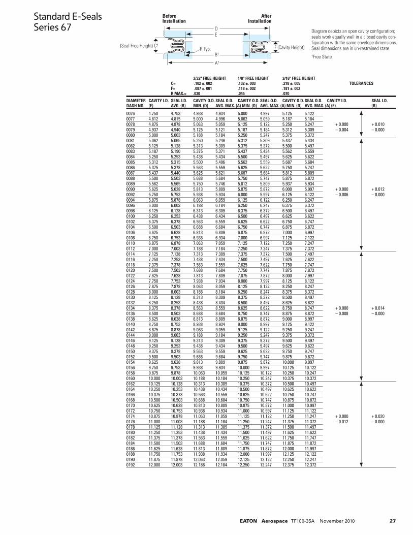
27EATON Aerospace TF100-35A November 2010
Standard E-SealsSeries 67
0076 4.750 4.753 4.938 4.934 5.000 4.997 5.125 5.1220077 4.812 4.815 5.000 4.996 5.062 5.059 5.187 5.1840078 4.875 4.878 5.063 5.059 5.125 5.122 5.250 5.247 + 0.000 + 0.0100079 4.937 4.940 5.125 5.121 5.187 5.184 5.312 5.309 – 0.004 – 0.0000080 5.000 5.003 5.188 5.184 5.250 5.247 5.375 5.3720081 5.062 5.065 5.250 5.246 5.312 5.309 5.437 5.4340082 5.125 5.128 5.313 5.309 5.375 5.372 5.500 5.4970083 5.187 5.190 5.375 5.371 5.437 5.434 5.562 5.5590084 5.250 5.253 5.438 5.434 5.500 5.497 5.625 5.6220085 5.312 5.315 5.500 5.496 5.562 5.559 5.687 5.6840086 5.375 5.378 5.563 5.559 5.625 5.622 5.750 5.7470087 5.437 5.440 5.625 5.621 5.687 5.684 5.812 5.8090088 5.500 5.503 5.688 5.684 5.750 5.747 5.875 5.8720089 5.562 5.565 5.750 5.746 5.812 5.809 5.937 5.9340090 5.625 5.628 5.813 5.809 5.875 5.872 6.000 5.997 + 0.000 + 0.0120092 5.750 5.753 5.938 5.934 6.000 5.997 6.125 6.122 – 0.006 – 0.0000094 5.875 5.878 6.063 6.059 6.125 6.122 6.250 6.2470096 6.000 6.003 6.188 6.184 6.250 6.247 6.375 6.372 0098 6.125 6.128 6.313 6.309 6.375 6.372 6.500 6.4970100 6.250 6.253 6.438 6.434 6.500 6.497 6.625 6.6220102 6.375 6.378 6.563 6.559 6.625 6.622 6.750 6.7470104 6.500 6.503 6.688 6.684 6.750 6.747 6.875 6.8720106 6.625 6.628 6.813 6.809 6.875 6.872 7.000 6.9970108 6.750 6.753 6.938 6.934 7.000 6.997 7.125 7.1220110 6.875 6.878 7.063 7.059 7.125 7.122 7.250 7.2470112 7.000 7.003 7.188 7.184 7.250 7.247 7.375 7.3720114 7.125 7.128 7.313 7.309 7.375 7.372 7.500 7.4970116 7.250 7.253 7.438 7.434 7.500 7.497 7.625 7.6220118 7.375 7.378 7.563 7.559 7.625 7.622 7.750 7.7470120 7.500 7.503 7.688 7.684 7.750 7.747 7.875 7.8720122 7.625 7.628 7.813 7.809 7.875 7.872 8.000 7.9970124 7.750 7.753 7.938 7.934 8.000 7.997 8.125 8.1220126 7.875 7.878 8.063 8.059 8.125 8.122 8.250 8.2470128 8.000 8.003 8.188 8.184 8.250 8.247 8.375 8.3720130 8.125 8.128 8.313 8.309 8.375 8.372 8.500 8.4970132 8.250 8.253 8.438 8.434 8.500 8.497 8.625 8.6220134 8.375 8.378 8.563 8.559 8.625 8.622 8.750 8.747 + 0.000 + 0.0140136 8.500 8.503 8.688 8.684 8.750 8.747 8.875 8.872 – 0.008 – 0.0000138 8.625 8.628 8.813 8.809 8.875 8.872 9.000 8.9970140 8.750 8.753 8.938 8.934 9.000 8.997 9.125 9.1220142 8.875 8.878 9.063 9.059 9.125 9.122 9.250 9.2470144 9.000 9.003 9.188 9.184 9.250 9.247 9.375 9.3720146 9.125 9.128 9.313 9.309 9.375 9.372 9.500 9.4970148 9.250 9.253 9.438 9.434 9.500 9.497 9.625 9.6220150 9.375 9.378 9.563 9.559 9.625 9.622 9.750 9.7470152 9.500 9.503 9.688 9.684 9.750 9.747 9.875 9.8720154 9.625 9.628 9.813 9.809 9.875 9.872 10.000 9.9970156 9.750 9.753 9.938 9.934 10.000 9.997 10.125 10.1220158 9.875 9.878 10.063 10.059 10.125 10.122 10.250 10.2470160 10.000 10.003 10.188 10.184 10.250 10.247 10.375 10.3720162 10.125 10.128 10.313 10.309 10.375 10.372 10.500 10.4970164 10.250 10.253 10.438 10.434 10.500 10.497 10.625 10.6220166 10.375 10.378 10.563 10.559 10.625 10.622 10.750 10.7470168 10.500 10.503 10.688 10.684 10.750 10.747 10.875 10.8720170 10.625 10.628 10.813 10.809 10.875 10.872 11.000 10.9970172 10.750 10.753 10.938 10.934 11.000 10.997 11.125 11.1220174 10.875 10.878 11.063 11.059 11.125 11.122 11.250 11.247 + 0.000 + 0.0200176 11.000 11.003 11.188 11.184 11.250 11.247 11.375 11.372 – 0.012 – 0.0000178 11.125 11.128 11.313 11.309 11.375 11.372 11.500 11.4970180 11.250 11.253 11.438 11.434 11.500 11.497 11.625 11.6220182 11.375 11.378 11.563 11.559 11.625 11.622 11.750 11.7470184 11.500 11.503 11.688 11.684 11.750 11.747 11.875 11.8720186 11.625 11.628 11.813 11.809 11.875 11.872 12.000 11.9970188 11.750 11.753 11.938 11.934 12.000 11.997 12.125 12.1220190 11.875 11.878 12.063 12.059 12.125 12.122 12.250 12.2470192 12.000 12.003 12.188 12.184 12.250 12.247 12.375 12.372
3/32" FREE HEIGHT 1/8" FREE HEIGHT 3/16" FREE HEIGHT C= .102 ±. 002 .132 ±. 003 .218 ±. 005 TOLERANCES F= .087 ±. 001 .118 ±. 002 .181 ±. 002 R MAX.= .030 .045 .070
DIAMETER CAVITY I.D. SEAL I.D. CAVITY O.D. SEAL O.D. CAVITY O.D. SEAL O.D. CAVITY O.D. SEAL O.D. CAVITY I.D. SEAL I.D.DASH NO. (E) AVG. (B) MIN. (D) AVG. MAX. (A) MIN. (D) AVG. MAX. (A) MIN. (D) AVG. MAX. (A) (E) (B)
Diagram depicts an open cavity confi guration; seals work equally well in a closed cavity con-fi guration with the same envelope dimensions. Seal dimensions are in un-restrained state.†Free State
DE
B†
A†
Before Installation
After Installation
(Seal Free Height) C† F (Cavity Height)R Typ.
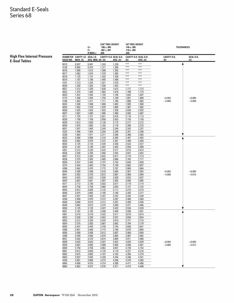
28 EATON Aerospace TF100-35A November 2010
Standard E-SealsSeries 68
High Flex Internal Pressure E-Seal Tables
0015 0.937 0.947 1.243 1.238 *** ***4136 0.965 0.975 1.271 1.266 *** ***0016 1.000 1.012 1.308 1.303 *** ***0017 1.062 1.074 1.370 1.365 *** ***0018 1.125 1.137 1.433 1.428 *** ***0019 1.187 1.199 1.495 1.490 *** ***4161 1.213 1.225 1.521 1.516 *** ***0020 1.250 1.262 1.558 1.553 *** ***0021 1.312 1.320 1.620 1.615 1.717 1.7120022 1.375 1.383 1.683 1.678 1.780 1.7750023 1.437 1.445 1.745 1.740 1.842 1.8373174 1.446 1.454 1.754 1.749 1.851 1.846 +0.002 +0.0004186 1.463 1.471 1.771 1.766 1.868 1.863 – 0.000 – 0.0080024 1.500 1.508 1.808 1.803 1.905 1.9000025 1.562 1.570 1.870 1.865 1.967 1.9620026 1.625 1.633 1.933 1.928 2.030 2.0250027 1.687 1.695 1.995 1.990 2.092 2.0874211 1.725 1.721 2.021 2.016 2.118 2.1130028 1.750 1.758 2.058 2.053 2.155 2.1500029 1.812 1.820 2.120 2.115 2.217 2.2120030 1.875 1.883 2.183 2.178 2.280 2.2750031 1.937 1.945 2.245 2.240 2.342 2.3373224 1.946 1.954 2.254 2.249 2.351 2.3464236 1.963 1.971 2.271 2.266 2.368 2.3630032 2.000 2.008 2.310 2.305 2.407 2.4020033 2.062 2.070 2.372 2.367 2.469 2.4640034 2.125 2.133 2.435 2.430 2.532 2.5270035 2.187 2.195 2.497 2.492 2.594 2.5894261 2.212 2.220 2.522 2.517 2.619 2.6140036 2.250 2.258 2.560 2.555 2.657 2.6520037 2.312 2.320 2.622 2.617 2.719 2.7140038 2.375 2.383 2.685 2.680 2.782 2.7770039 2.437 2.445 2.747 2.742 2.844 2.8393274 2.444 2.463 2.754 2.749 2.862 2.8574286 2.462 2.470 2.772 2.767 2.869 2.8640040 2.500 2.508 2.810 2.805 2.907 2.902 +0.003 +0.0000041 2.562 2.570 2.872 2.867 2.969 2.964 – 0.000 – 0.0100042 2.625 2.633 2.935 2.930 3.032 3.0270043 2.687 2.691 2.997 2.992 3.090 3.0854311 2.712 2.720 3.022 3.017 3.119 3.1140044 2.750 2.758 3.060 3.055 3.157 3.1520045 2.812 2.820 3.122 3.117 3.219 3.2140046 2.875 2.883 3.185 3.180 3.282 3.2770047 2.937 2.945 3.247 3.242 3.344 3.3394336 2.940 2.970 3.272 3.267 3.369 3.3640048 3.000 3.010 3.312 3.307 3.409 3.4040049 3.062 3.072 3.374 3.369 3.471 3.4660050 3.125 3.135 3.437 3.432 3.534 3.5290051 3.187 3.195 3.499 3.494 3.596 3.5914361 3.210 3.218 3.522 3.517 3.619 3.6140052 3.250 3.258 3.562 3.557 3.659 3.6540053 3.312 3.320 3.624 3.619 3.721 3.7160054 3.375 3.383 3.687 3.682 3.784 3.7790055 3.437 3.445 3.749 3.744 3.846 3.8414386 3.461 3.469 3.773 3.768 3.870 3.8650056 3.500 3.508 3.812 3.807 3.909 3.9043386 3.558 3.566 3.870 3.865 3.967 3.9620057 3.562 3.570 3.874 3.869 3.971 3.9660058 3.625 3.633 3.937 3.932 4.034 4.029 +0.004 +0.0000059 3.687 3.695 3.999 3.994 4.096 4.091 – 0.000 – 0.0120060 3.750 3.758 4.062 4.057 4.159 4.1540061 3.812 3.820 4.124 4.119 4.221 4.2160062 3.875 3.883 4.187 4.182 4.284 4.2790063 3.937 3.945 4.249 4.244 4.346 4.3414436 3.961 3.969 4.273 4.268 4.370 4.3650064 4.000 4.010 4.314 4.309 4.411 4.4060065 4.062 4.072 4.376 4.371 4.473 4.468
3/32" FREE HEIGHT 1/8" FREE HEIGHT C= .108 ±. 005 .140 ±. 005 TOLERANCES F= .087 ±. 001 .118 ±. 002 R MAX.= .030 .045
DIAMETER CAVITY I.D. SEAL I.D. CAVITY O.D. SEAL O.D. CAVITY O.D. SEAL O.D. CAVITY O.D. SEAL O.D.DASH NO. MAX. (E) AVG. MIN. (B) (D) AVG. (A) (D) AVG. (A) (D) (A)
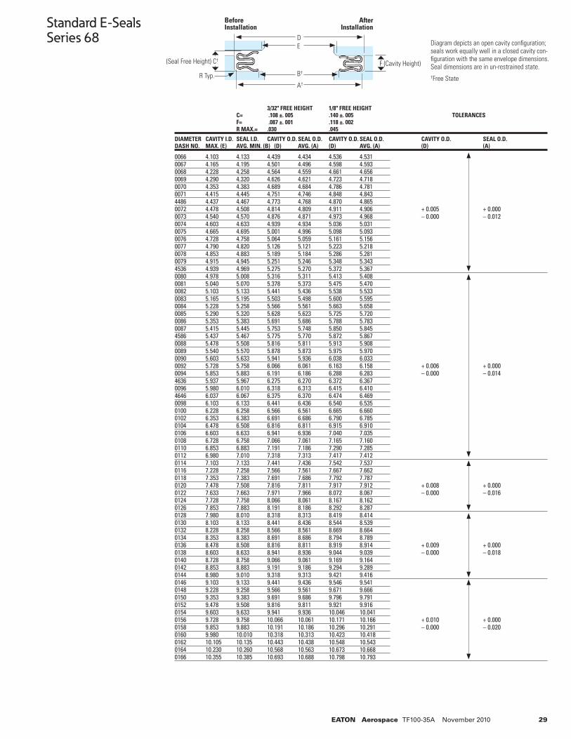
29EATON Aerospace TF100-35A November 2010
Standard E-SealsSeries 68
0066 4.103 4.133 4.439 4.434 4.536 4.5310067 4.165 4.195 4.501 4.496 4.598 4.5930068 4.228 4.258 4.564 4.559 4.661 4.6560069 4.290 4.320 4.626 4.621 4.723 4.7180070 4.353 4.383 4.689 4.684 4.786 4.7810071 4.415 4.445 4.751 4.746 4.848 4.8434486 4.437 4.467 4.773 4.768 4.870 4.8650072 4.478 4.508 4.814 4.809 4.911 4.906 + 0.005 + 0.0000073 4.540 4.570 4.876 4.871 4.973 4.968 – 0.000 – 0.0120074 4.603 4.633 4.939 4.934 5.036 5.0310075 4.665 4.695 5.001 4.996 5.098 5.0930076 4.728 4.758 5.064 5.059 5.161 5.1560077 4.790 4.820 5.126 5.121 5.223 5.2180078 4.853 4.883 5.189 5.184 5.286 5.2810079 4.915 4.945 5.251 5.246 5.348 5.3434536 4.939 4.969 5.275 5.270 5.372 5.3670080 4.978 5.008 5.316 5.311 5.413 5.4080081 5.040 5.070 5.378 5.373 5.475 5.4700082 5.103 5.133 5.441 5.436 5.538 5.5330083 5.165 5.195 5.503 5.498 5.600 5.5950084 5.228 5.258 5.566 5.561 5.663 5.6580085 5.290 5.320 5.628 5.623 5.725 5.7200086 5.353 5.383 5.691 5.686 5.788 5.7830087 5.415 5.445 5.753 5.748 5.850 5.845 4586 5.437 5.467 5.775 5.770 5.872 5.867 0088 5.478 5.508 5.816 5.811 5.913 5.9080089 5.540 5.570 5.878 5.873 5.975 5.9700090 5.603 5.633 5.941 5.936 6.038 6.0330092 5.728 5.758 6.066 6.061 6.163 6.158 + 0.006 + 0.0000094 5.853 5.883 6.191 6.186 6.288 6.283 – 0.000 – 0.0144636 5.937 5.967 6.275 6.270 6.372 6.3670096 5.980 6.010 6.318 6.313 6.415 6.4104646 6.037 6.067 6.375 6.370 6.474 6.4690098 6.103 6.133 6.441 6.436 6.540 6.5350100 6.228 6.258 6.566 6.561 6.665 6.6600102 6.353 6.383 6.691 6.686 6.790 6.7850104 6.478 6.508 6.816 6.811 6.915 6.910 0106 6.603 6.633 6.941 6.936 7.040 7.035 0108 6.728 6.758 7.066 7.061 7.165 7.1600110 6.853 6.883 7.191 7.186 7.290 7.2850112 6.980 7.010 7.318 7.313 7.417 7.4120114 7.103 7.133 7.441 7.436 7.542 7.5370116 7.228 7.258 7.566 7.561 7.667 7.6620118 7.353 7.383 7.691 7.686 7.792 7.7870120 7.478 7.508 7.816 7.811 7.917 7.912 + 0.008 + 0.0000122 7.633 7.663 7.971 7.966 8.072 8.067 – 0.000 – 0.0160124 7.728 7.758 8.066 8.061 8.167 8.162 0126 7.853 7.883 8.191 8.186 8.292 8.2870128 7.980 8.010 8.318 8.313 8.419 8.4140130 8.103 8.133 8.441 8.436 8.544 8.5390132 8.228 8.258 8.566 8.561 8.669 8.6640134 8.353 8.383 8.691 8.686 8.794 8.7890136 8.478 8.508 8.816 8.811 8.919 8.914 + 0.009 + 0.0000138 8.603 8.633 8.941 8.936 9.044 9.039 – 0.000 – 0.0180140 8.728 8.758 9.066 9.061 9.169 9.1640142 8.853 8.883 9.191 9.186 9.294 9.2890144 8.980 9.010 9.318 9.313 9.421 9.4160146 9.103 9.133 9.441 9.436 9.546 9.5410148 9.228 9.258 9.566 9.561 9.671 9.6660150 9.353 9.383 9.691 9.686 9.796 9.7910152 9.478 9.508 9.816 9.811 9.921 9.9160154 9.603 9.633 9.941 9.936 10.046 10.0410156 9.728 9.758 10.066 10.061 10.171 10.166 + 0.010 + 0.0000158 9.853 9.883 10.191 10.186 10.296 10.291 – 0.000 – 0.0200160 9.980 10.010 10.318 10.313 10.423 10.4180162 10.105 10.135 10.443 10.438 10.548 10.5430164 10.230 10.260 10.568 10.563 10.673 10.6680166 10.355 10.385 10.693 10.688 10.798 10.793
3/32" FREE HEIGHT 1/8" FREE HEIGHT C= .108 ±. 005 .140 ±. 005 TOLERANCES F= .087 ±. 001 .118 ±. 002 R MAX.= .030 .045
DIAMETER CAVITY I.D. SEAL I.D. CAVITY O.D. SEAL O.D. CAVITY O.D. SEAL O.D. CAVITY O.D. SEAL O.D.DASH NO. MAX. (E) AVG. MIN. (B) (D) AVG. (A) (D) AVG. (A) (D) (A)
Diagram depicts an open cavity confi guration; seals work equally well in a closed cavity con-fi guration with the same envelope dimensions. Seal dimensions are in un-restrained state.†Free State
DE
B†
A†
Before Installation
After Installation
(Seal Free Height) C† F (Cavity Height)
R Typ.
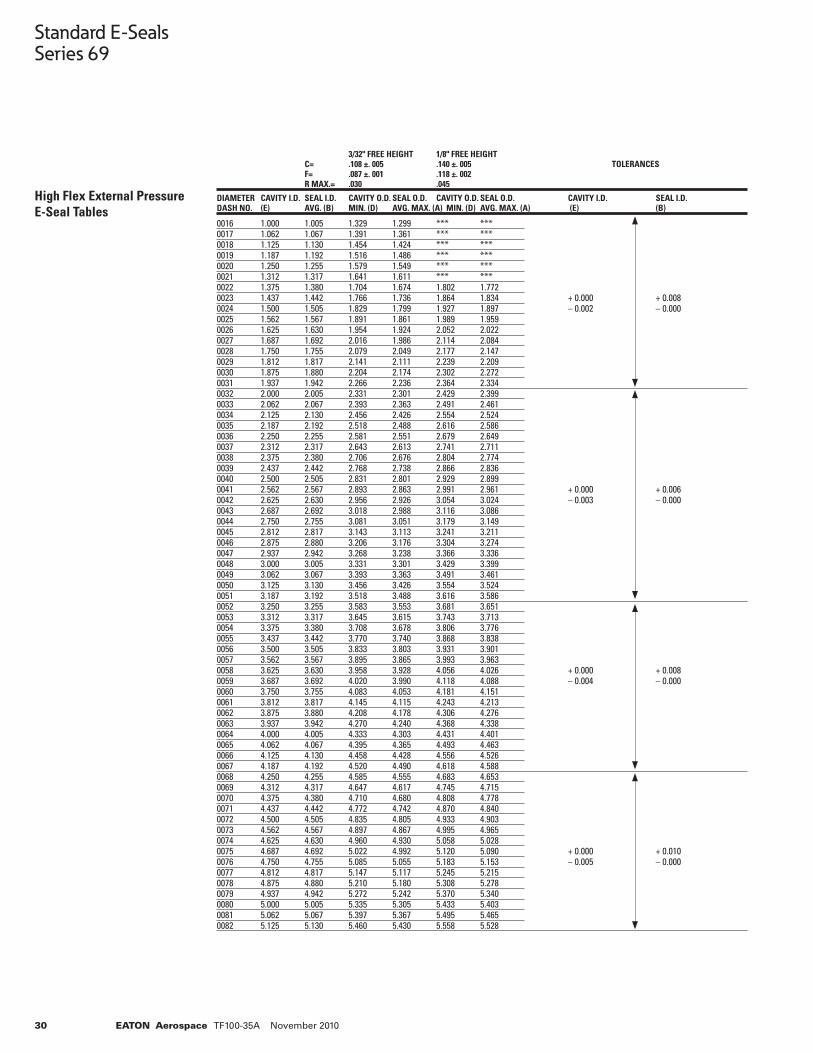
30 EATON Aerospace TF100-35A November 2010
Standard E-SealsSeries 69
High Flex External Pressure E-Seal Tables
0016 1.000 1.005 1.329 1.299 *** *** 0017 1.062 1.067 1.391 1.361 *** ***0018 1.125 1.130 1.454 1.424 *** ***0019 1.187 1.192 1.516 1.486 *** ***0020 1.250 1.255 1.579 1.549 *** ***0021 1.312 1.317 1.641 1.611 *** ***0022 1.375 1.380 1.704 1.674 1.802 1.7720023 1.437 1.442 1.766 1.736 1.864 1.834 + 0.000 + 0.0080024 1.500 1.505 1.829 1.799 1.927 1.897 – 0.002 – 0.0000025 1.562 1.567 1.891 1.861 1.989 1.959 0026 1.625 1.630 1.954 1.924 2.052 2.0220027 1.687 1.692 2.016 1.986 2.114 2.0840028 1.750 1.755 2.079 2.049 2.177 2.1470029 1.812 1.817 2.141 2.111 2.239 2.2090030 1.875 1.880 2.204 2.174 2.302 2.2720031 1.937 1.942 2.266 2.236 2.364 2.3340032 2.000 2.005 2.331 2.301 2.429 2.3990033 2.062 2.067 2.393 2.363 2.491 2.4610034 2.125 2.130 2.456 2.426 2.554 2.5240035 2.187 2.192 2.518 2.488 2.616 2.5860036 2.250 2.255 2.581 2.551 2.679 2.6490037 2.312 2.317 2.643 2.613 2.741 2.7110038 2.375 2.380 2.706 2.676 2.804 2.7740039 2.437 2.442 2.768 2.738 2.866 2.8360040 2.500 2.505 2.831 2.801 2.929 2.8990041 2.562 2.567 2.893 2.863 2.991 2.961 + 0.000 + 0.006 0042 2.625 2.630 2.956 2.926 3.054 3.024 – 0.003 – 0.0000043 2.687 2.692 3.018 2.988 3.116 3.0860044 2.750 2.755 3.081 3.051 3.179 3.1490045 2.812 2.817 3.143 3.113 3.241 3.2110046 2.875 2.880 3.206 3.176 3.304 3.2740047 2.937 2.942 3.268 3.238 3.366 3.3360048 3.000 3.005 3.331 3.301 3.429 3.3990049 3.062 3.067 3.393 3.363 3.491 3.4610050 3.125 3.130 3.456 3.426 3.554 3.5240051 3.187 3.192 3.518 3.488 3.616 3.5860052 3.250 3.255 3.583 3.553 3.681 3.6510053 3.312 3.317 3.645 3.615 3.743 3.7130054 3.375 3.380 3.708 3.678 3.806 3.7760055 3.437 3.442 3.770 3.740 3.868 3.8380056 3.500 3.505 3.833 3.803 3.931 3.9010057 3.562 3.567 3.895 3.865 3.993 3.9630058 3.625 3.630 3.958 3.928 4.056 4.026 + 0.000 + 0.0080059 3.687 3.692 4.020 3.990 4.118 4.088 – 0.004 – 0.0000060 3.750 3.755 4.083 4.053 4.181 4.1510061 3.812 3.817 4.145 4.115 4.243 4.2130062 3.875 3.880 4.208 4.178 4.306 4.2760063 3.937 3.942 4.270 4.240 4.368 4.3380064 4.000 4.005 4.333 4.303 4.431 4.4010065 4.062 4.067 4.395 4.365 4.493 4.4630066 4.125 4.130 4.458 4.428 4.556 4.5260067 4.187 4.192 4.520 4.490 4.618 4.5880068 4.250 4.255 4.585 4.555 4.683 4.6530069 4.312 4.317 4.647 4.617 4.745 4.7150070 4.375 4.380 4.710 4.680 4.808 4.7780071 4.437 4.442 4.772 4.742 4.870 4.8400072 4.500 4.505 4.835 4.805 4.933 4.9030073 4.562 4.567 4.897 4.867 4.995 4.9650074 4.625 4.630 4.960 4.930 5.058 5.028 0075 4.687 4.692 5.022 4.992 5.120 5.090 + 0.000 + 0.0100076 4.750 4.755 5.085 5.055 5.183 5.153 – 0.005 – 0.0000077 4.812 4.817 5.147 5.117 5.245 5.215 0078 4.875 4.880 5.210 5.180 5.308 5.2780079 4.937 4.942 5.272 5.242 5.370 5.3400080 5.000 5.005 5.335 5.305 5.433 5.4030081 5.062 5.067 5.397 5.367 5.495 5.4650082 5.125 5.130 5.460 5.430 5.558 5.528
3/32" FREE HEIGHT 1/8" FREE HEIGHT C= .108 ±. 005 .140 ±. 005 TOLERANCES F= .087 ±. 001 .118 ±. 002 R MAX.= .030 .045
DIAMETER CAVITY I.D. SEAL I.D. CAVITY O.D. SEAL O.D. CAVITY O.D. SEAL O.D. CAVITY I.D. SEAL I.D.DASH NO. (E) AVG. (B) MIN. (D) AVG. MAX. (A) MIN. (D) AVG. MAX. (A) (E) (B)
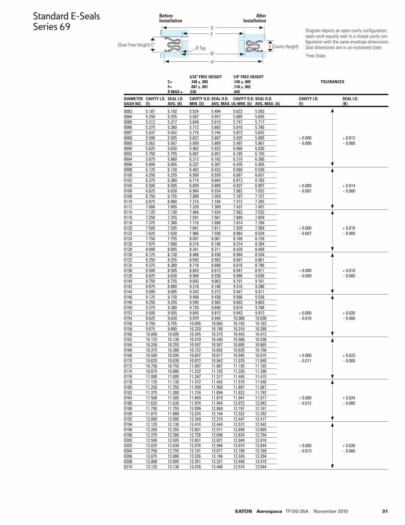
31EATON Aerospace TF100-35A November 2010
Standard E-SealsSeries 69
0083 5.187 5.192 5.524 5.494 5.622 5.5920084 5.250 5.255 5.587 5.557 5.685 5.6550085 5.312 5.317 5.649 5.619 5.747 5.7170086 5.375 5.380 5.712 5.682 5.810 5.7800087 5.437 5.442 5.774 5.744 5.872 5.8420088 5.500 5.505 5.837 5.807 5.935 5.905 + 0.000 + 0.0120089 5.562 5.567 5.899 5.869 5.997 5.967 – 0.006 – 0.0000090 5.625 5.630 5.962 5.932 6.060 6.0300092 5.750 5.755 6.087 6.057 6.185 6.1550094 5.875 5.880 6.212 6.182 6.310 6.2800096 6.000 6.005 6.337 6.307 6.435 6.4050098 6.125 6.130 6.462 6.432 6.560 6.5300100 6.250 6.255 6.589 6.559 6.687 6.6570102 6.375 6.380 6.714 6.684 6.812 6.7820104 6.500 6.505 6.839 6.809 6.937 6.907 + 0.000 + 0.0140106 6.625 6.630 6.964 6.934 7.062 7.032 – 0.007 – 0.0000108 6.750 6.755 7.089 7.059 7.187 7.1570110 6.875 6.880 7.214 7.184 7.312 7.2820112 7.000 7.005 7.339 7.309 7.437 7.4070114 7.125 7.130 7.464 7.434 7.562 7.5320116 7.250 7.255 7.591 7.561 7.689 7.6590118 7.375 7.380 7.716 7.686 7.814 7.7840120 7.500 7.505 7.841 7.811 7.939 7.909 + 0.000 + 0.0160122 7.625 7.630 7.966 7.936 8.064 8.034 – 0.007 – 0.0000124 7.750 7.755 8.091 8.061 8.189 8.1590126 7.875 7.880 8.216 8.186 8.314 8.2840128 8.000 8.005 8.341 8.311 8.439 8.4090130 8.125 8.130 8.466 8.436 8.564 8.5340132 8.250 8.255 8.593 8.563 8.691 8.6610134 8.375 8.380 8.718 8.688 8.816 8.7860136 8.500 8.505 8.843 8.813 8.941 8.911 + 0.000 + 0.0180138 8.625 8.630 8.968 8.938 9.066 9.036 – 0.009 – 0.0000140 8.750 8.755 9.093 9.063 9.191 9.1610142 8.875 8.880 9.218 9.188 9.316 9.2860144 9.000 9.005 9.343 9.313 9.441 9.4110146 9.125 9.130 9.468 9.438 9.566 9.5360148 9.250 9.255 9.595 9.565 9.693 9.6630150 9.375 9.380 9.720 9.690 9.818 9.7880152 9.500 9.505 9.845 9.815 9.943 9.913 + 0.000 + 0.0200154 9.625 9.630 9.970 9.940 10.068 10.038 – 0.010 – 0.0000156 9.750 9.755 10.095 10.065 10.193 10.1630158 9.875 9.880 10.220 10.190 10.318 10.2880160 10.000 10.005 10.345 10.315 10.443 10.4130162 10.125 10.130 10.470 10.440 10.568 10.5380164 10.250 10.255 10.597 10.567 10.695 10.6650166 10.375 10.380 10.722 10.692 10.820 10.7900168 10.500 10.505 10.847 10.817 10.945 10.915 + 0.000 + 0.0220170 10.625 10.630 10.972 10.942 11.070 11.040 – 0.011 – 0.0000172 10.750 10.755 11.097 11.067 11.195 11.1650174 10.875 10.880 11.222 11.192 11.320 11.2900176 11.000 11.005 11.347 11.317 11.445 11.4150178 11.125 11.130 11.472 11.442 11.570 11.5400180 11.250 11.255 11.599 11.569 11.697 11.6670182 11.375 11.380 11.724 11.694 11.822 11.7920184 11.500 11.505 11.849 11.819 11.947 11.917 + 0.000 + 0.0240186 11.625 11.630 11.974 11.944 12.072 12.042 – 0.012 – 0.0000188 11.750 11.755 12.099 12.069 12.197 12.1670190 11.875 11.880 12.224 12.194 12.322 12.2920192 12.000 12.005 12.349 12.319 12.447 12.4170194 12.125 12.130 12.474 12.444 12.572 12.5420196 12.250 12.255 12.601 12.571 12.699 12.6690198 12.375 12.380 12.726 12.696 12.824 12.7940200 12.500 12.505 12.851 12.821 12.949 12.9190202 12.625 12.630 12.976 12.946 13.074 13.044 + 0.000 + 0.0260204 12.750 12.755 13.101 13.071 13.199 13.169 – 0.013 – 0.0000206 12.875 12.880 13.226 13.196 13.324 13.2940208 13.000 13.005 13.351 13.321 13.449 13.4190210 13.125 13.130 13.476 13.446 13.574 13.544
3/32" FREE HEIGHT 1/8" FREE HEIGHT C= .108 ±. 005 .140 ±. 005 TOLERANCES F= .087 ±. 001 .118 ±. 002 R MAX.= .030 .045
DIAMETER CAVITY I.D. SEAL I.D. CAVITY O.D. SEAL O.D. CAVITY O.D. SEAL O.D. CAVITY I.D. SEAL I.D.DASH NO. (E) AVG. (B) MIN. (D) AVG. MAX. (A) MIN. (D) AVG. MAX. (A) (E) (B)
DE
B†
A†
Before Installation
After Installation
(Seal Free Height) C† F (Cavity Height)R Typ.
Diagram depicts an open cavity confi guration; seals work equally well in a closed cavity con-fi guration with the same envelope dimensions. Seal dimensions are in un-restrained state.†Free State
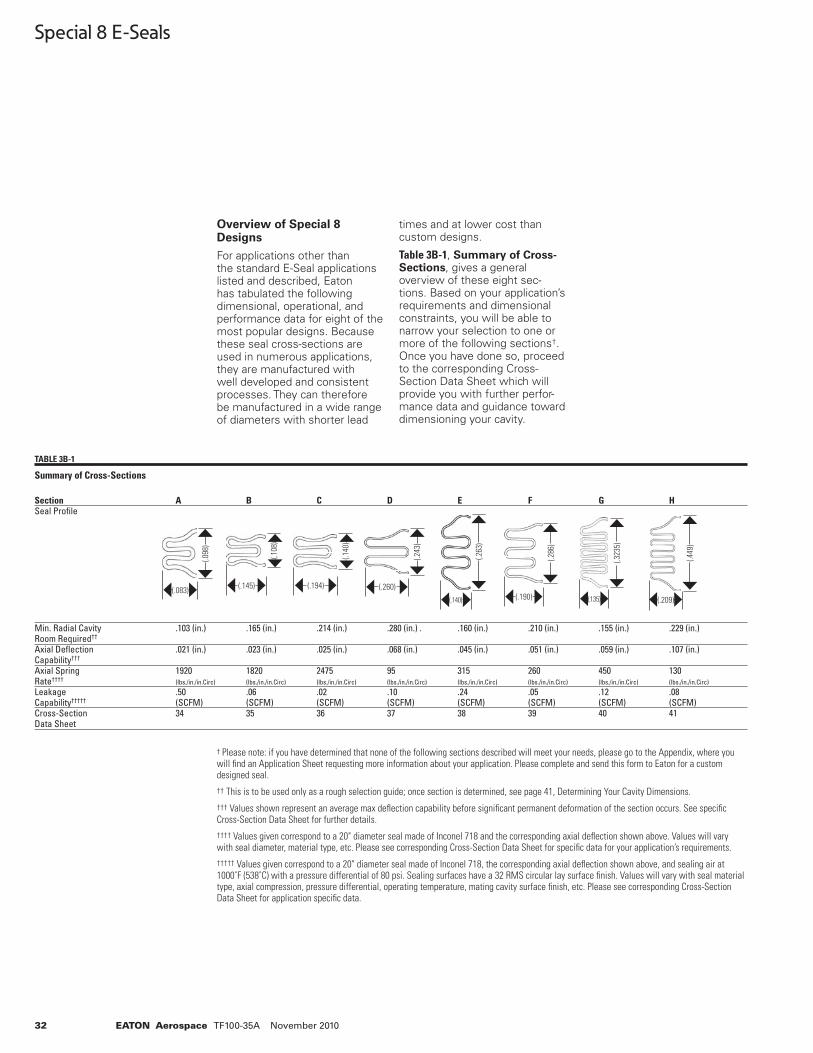
32 EATON Aerospace TF100-35A November 2010
Special 8 E-Seals
Overview of Special 8 Designs
For applications other than the standard E-Seal applications listed and described, Eaton has tabulated the following dimensional, operational, and performance data for eight of the most popular designs. Because these seal cross-sections are used in numerous applications, they are manufactured with well developed and consistent processes. They can therefore be manufactured in a wide range of diameters with shorter lead
times and at lower cost than custom designs.
Table 3B-1, Summary of Cross-Sections, gives a general overview of these eight sec-tions. Based on your application’s requirements and dimensional constraints, you will be able to narrow your selection to one or more of the following sections†. Once you have done so, proceed to the corresponding Cross-Section Data Sheet which will provide you with further perfor-mance data and guidance toward dimensioning your cavity.
† Please note: if you have determined that none of the following sections described will meet your needs, please go to the Appendix, where you will fi nd an Application Sheet requesting more information about your application. Please complete and send this form to Eaton for a custom designed seal.
†† This is to be used only as a rough selection guide; once section is determined, see page 41, Determining Your Cavity Dimensions.
††† Values shown represent an average max defl ection capability before signifi cant permanent deformation of the section occurs. See specifi c Cross-Section Data Sheet for further details.
†††† Values given correspond to a 20" diameter seal made of Inconel 718 and the corresponding axial defl ection shown above. Values will vary with seal diameter, material type, etc. Please see corresponding Cross-Section Data Sheet for specifi c data for your application’s requirements.
††††† Values given correspond to a 20" diameter seal made of Inconel 718, the corresponding axial defl ection shown above, and sealing air at 1000˚F (538˚C) with a pressure differential of 80 psi. Sealing surfaces have a 32 RMS circular lay surface fi nish. Values will vary with seal material type, axial compression, pressure differential, operating temperature, mating cavity surface fi nish, etc. Please see corresponding Cross-Section Data Sheet for application specifi c data.
Section A B C D E F G H Seal Profi le
Min. Radial Cavity .103 (in.) .165 (in.) .214 (in.) .280 (in.) . .160 (in.) .210 (in.) .155 (in.) .229 (in.)Room Required††
Axial Defl ection .021 (in.) .023 (in.) .025 (in.) .068 (in.) .045 (in.) .051 (in.) .059 (in.) .107 (in.)Capability††† Axial Spring 1920 1820 2475 95 315 260 450 130Rate†††† (lbs./in./in.Circ) (lbs./in./in.Circ) (lbs./in./in.Circ) (lbs./in./in.Circ) (lbs./in./in.Circ) (lbs./in./in.Circ) (lbs./in./in.Circ) (lbs./in./in.Circ)
Leakage .50 .06 .02 .10 .24 .05 .12 .08Capability††††† (SCFM) (SCFM) (SCFM) (SCFM) (SCFM) (SCFM) (SCFM) (SCFM) Cross-Section 34 35 36 37 38 39 40 41Data Sheet
TABLE 3B-1
Summary of Cross-Sections
(.098
)
(.083)
(.108
)
(.145)
(.243
)
(.260)
(.263
)
(.140)
(.286
)
(.190)
(.449
)
(.209)
(.140
)
(.194)
(.323
5)
(.135)
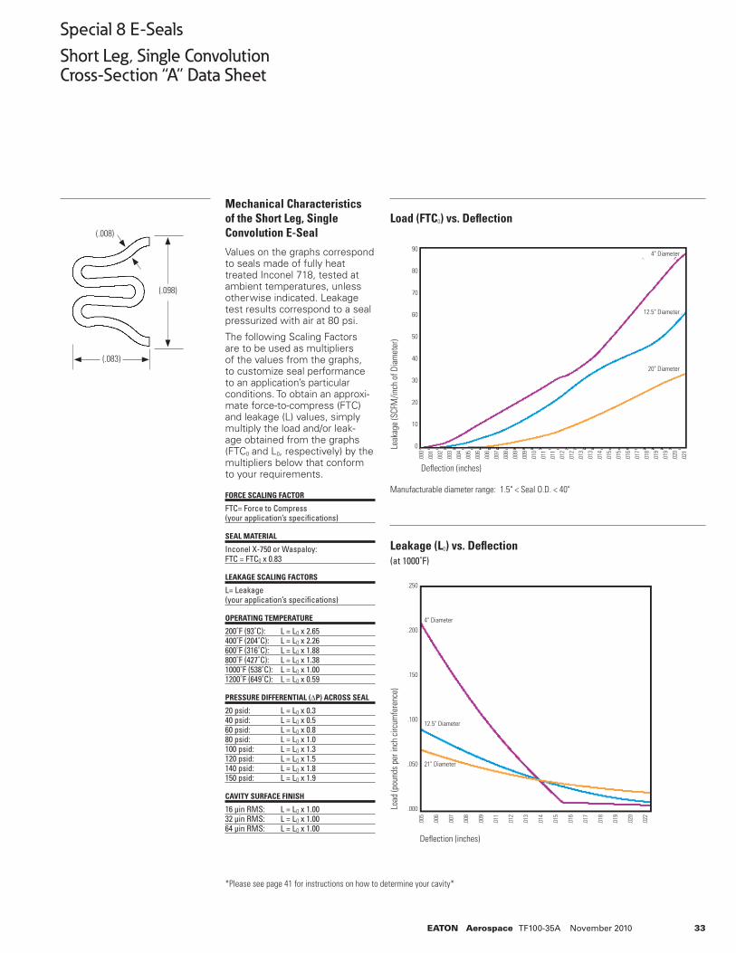
33EATON Aerospace TF100-35A November 2010
Special 8 E-Seals
Short Leg, Single ConvolutionCross-Section “A” Data Sheet
*Please see page 41 for instructions on how to determine your cavity*
Load (FTC0) vs. Defl ection
Leakage (L0) vs. Defl ection(at 1000˚F)
(.008)
(.083)
(.098)
Defl ection (inches)
Load
(pou
nds
per i
nch
circ
umfe
renc
e)
Manufacturable diameter range: 1.5" < Seal O.D. < 40"
Defl ection (inches)
Leak
age
(SCF
M/in
ch o
f Dia
met
er)
Mechanical Characteristics of the Short Leg, Single Convolution E-Seal
Values on the graphs correspond to seals made of fully heat treated Inconel 718, tested at ambient temperatures, unless otherwise indicated. Leakage test results correspond to a seal pressurized with air at 80 psi.
The following Scaling Factors are to be used as multipliers of the values from the graphs, to customize seal performance to an application’s particular conditions. To obtain an approxi-mate force-to-compress (FTC) and leakage (L) values, simply multiply the load and/or leak-age obtained from the graphs (FTC0 and L0, respectively) by the multipliers below that conform to your requirements.
FORCE SCALING FACTOR
FTC= Force to Compress(your application’s specifi cations)
SEAL MATERIAL
Inconel X-750 or Waspaloy:FTC = FTC0 x 0.83
LEAKAGE SCALING FACTORS
L= Leakage(your application’s specifi cations)
OPERATING TEMPERATURE
200˚F (93˚C): L = L0 x 2.65400˚F (204˚C): L = L0 x 2.26600˚F (316˚C): L = L0 x 1.88800˚F (427˚C): L = L0 x 1.381000˚F (538˚C): L = L0 x 1.001200˚F (649˚C): L = L0 x 0.59
PRESSURE DIFFERENTIAL (ΔP) ACROSS SEAL
20 psid: L = L0 x 0.340 psid: L = L0 x 0.560 psid: L = L0 x 0.880 psid: L = L0 x 1.0100 psid: L = L0 x 1.3120 psid: L = L0 x 1.5140 psid: L = L0 x 1.8150 psid: L = L0 x 1.9
CAVITY SURFACE FINISH
16 µin RMS: L = L0 x 1.0032 µin RMS: L = L0 x 1.0064 µin RMS: L = L0 x 1.00
90
80
70
60
50
40
30
20
10
0
.000
.001
.002
.003
.004
.005
.006
.006
.007
.008
.009
.009
.010
.011
.011
.012
.012
.013
.013
.014
.015
.015
.016
.017
.018
.019
.019
.020
.021
4" Diameter
12.5" Diameter
20" Diameter
21" Diameter
4" Diameter
12.5" Diameter
.250
.200
.150
.100
.050
.000
.005
.006
.007
.008
.009
.011
.012
.013
.014
.015
.016
.017
.018
.019
.020
.022
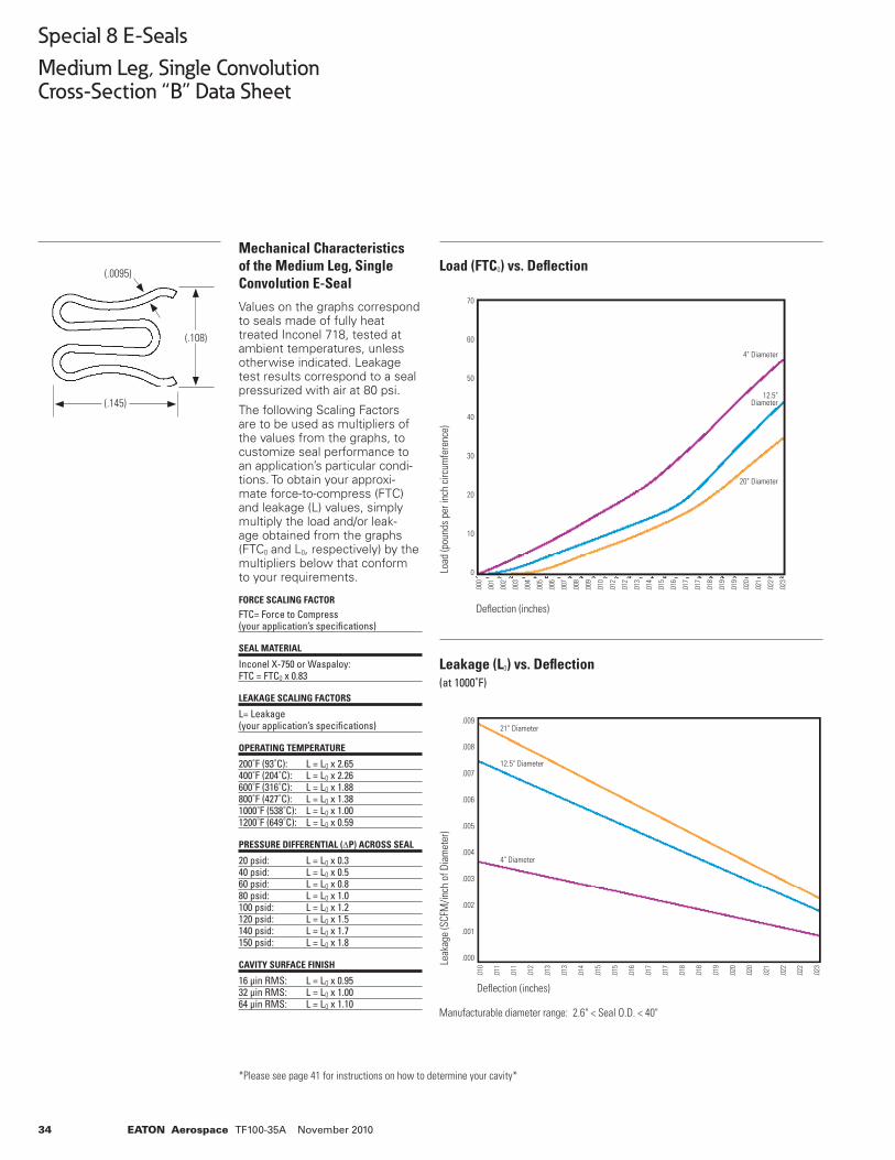
34 EATON Aerospace TF100-35A November 2010
Special 8 E-Seals
Medium Leg, Single ConvolutionCross-Section “B” Data Sheet
Mechanical Characteristics of the Medium Leg, Single Convolution E-Seal
Values on the graphs correspond to seals made of fully heat treated Inconel 718, tested at ambient temperatures, unless otherwise indicated. Leakage test results correspond to a seal pressurized with air at 80 psi.
The following Scaling Factors are to be used as multipliers of the values from the graphs, to customize seal performance to an application’s particular condi-tions. To obtain your approxi-mate force-to-compress (FTC) and leakage (L) values, simply multiply the load and/or leak-age obtained from the graphs (FTC0 and L0, respectively) by the multipliers below that conform to your requirements.
FORCE SCALING FACTOR
FTC= Force to Compress(your application’s specifi cations)
SEAL MATERIAL
Inconel X-750 or Waspaloy:FTC = FTC0 x 0.83
LEAKAGE SCALING FACTORS
L= Leakage(your application’s specifi cations)
OPERATING TEMPERATURE
200˚F (93˚C): L = L0 x 2.65400˚F (204˚C): L = L0 x 2.26600˚F (316˚C): L = L0 x 1.88800˚F (427˚C): L = L0 x 1.381000˚F (538˚C): L = L0 x 1.001200˚F (649˚C): L = L0 x 0.59
PRESSURE DIFFERENTIAL (ΔP) ACROSS SEAL
20 psid: L = L0 x 0.340 psid: L = L0 x 0.560 psid: L = L0 x 0.880 psid: L = L0 x 1.0100 psid: L = L0 x 1.2120 psid: L = L0 x 1.5140 psid: L = L0 x 1.7150 psid: L = L0 x 1.8
CAVITY SURFACE FINISH
16 µin RMS: L = L0 x 0.9532 µin RMS: L = L0 x 1.0064 µin RMS: L = L0 x 1.10
Manufacturable diameter range: 2.6" < Seal O.D. < 40"
*Please see page 41 for instructions on how to determine your cavity*
Load (FTC0) vs. Defl ection
Leakage (L0) vs. Defl ection(at 1000˚F)
Load
(pou
nds
per i
nch
circ
umfe
renc
e)
Defl ection (inches)
Leak
age
(SCF
M/in
ch o
f Dia
met
er)
Defl ection (inches)
(.0095)
(.145)
(.108)
70
60
50
40
30
20
10
0
.000
.001
.002
.003
.004
.005
.006
.007
.008
.009
.010
.012
.012
.013
.014
.015
.016
.017
.017
.018
.019
.019
.020
.021
.022
.023
.009
.008
.007
.006
.005
.004
.003
.002
.001
.000
.010
.011
.011
.012
.013
.013
.014
.015
.015
.016
.017
.017
.018
.018
.019
.020
.020
.021
.022
.022
.023
4" Diameter
12.5" Diameter
20" Diameter
21" Diameter
12.5" Diameter
4" Diameter
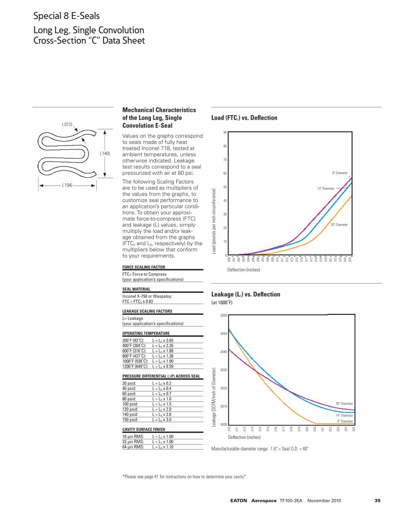
35EATON Aerospace TF100-35A November 2010
Special 8 E-Seals
Long Leg, Single ConvolutionCross-Section “C” Data Sheet
Manufacturable diameter range: 1.6" < Seal O.D. < 40"
*Please see page 41 for instructions on how to determine your cavity*
Load (FTC0) vs. Defl ection
Leakage (L0) vs. Defl ection(at 1000˚F)
Defl ection (inches)
Defl ection (inches)
(.012)
(.194)
(.140)
Load
(pou
nds
per i
nch
circ
umfe
renc
e) Le
akag
e (S
CFM
/inch
of D
iam
eter
)
Mechanical Characteristics of the Long Leg, Single Convolution E-Seal
Values on the graphs correspond to seals made of fully heat treated Inconel 718, tested at ambient temperatures, unless otherwise indicated. Leakage test results correspond to a seal pressurized with air at 80 psi.
The following Scaling Factors are to be used as multipliers of the values from the graphs, to customize seal performance to an application’s particular condi-tions. To obtain your approxi-mate force-to-compress (FTC) and leakage (L) values, simply multiply the load and/or leak-age obtained from the graphs (FTC0 and L0, respectively) by the multipliers below that conform to your requirements.
FORCE SCALING FACTOR
FTC= Force to Compress(your application’s specifi cations)
SEAL MATERIAL
Inconel X-750 or Waspaloy:FTC = FTC0 x 0.83
LEAKAGE SCALING FACTORS
L= Leakage(your application’s specifi cations)
OPERATING TEMPERATURE
200˚F (93˚C): L = L0 x 2.65400˚F (204˚C): L = L0 x 2.26600˚F (316˚C): L = L0 x 1.88800˚F (427˚C): L = L0 x 1.381000˚F (538˚C): L = L0 x 1.001200˚F (649˚C): L = L0 x 0.59
PRESSURE DIFFERENTIAL (ΔP) ACROSS SEAL
20 psid: L = L0 x 0.240 psid: L = L0 x 0.460 psid: L = L0 x 0.780 psid: L = L0 x 1.0100 psid: L = L0 x 1.5120 psid: L = L0 x 2.0140 psid: L = L0 x 2.6150 psid: L = L0 x 3.0
CAVITY SURFACE FINISH
16 µin RMS: L = L0 x 1.0032 µin RMS: L = L0 x 1.0064 µin RMS: L = L0 x 1.10
90
80
70
60
50
40
30
20
10
0
.000
.001
.002
.003
.004
.005
.006
.007
.008
.009
.010
.011
.012
.013
.015
.016
.017
.017
.018
.019
.020
.021
.022
.023
.024
.025
8" Diameter
14" Diameter
20" Diameter
20" Diameter
14" Diameter
8" Diameter
.0060
.0050
.0040
.0030
.0020
.0010
.0000
.010
.011
.012
.013
.014
.015
.016
.017
.018
.019
.020
.020
.021
.022
.023
.024
.025
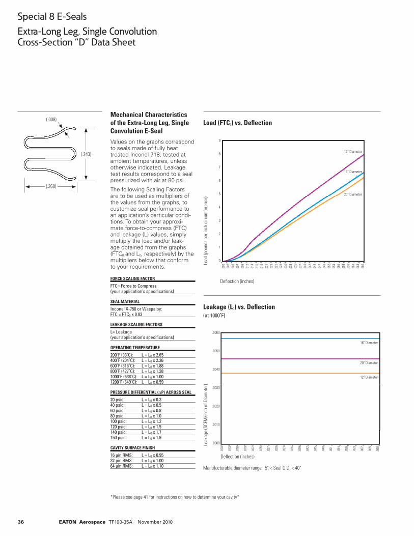
36 EATON Aerospace TF100-35A November 2010
Special 8 E-Seals
Extra-Long Leg, Single ConvolutionCross-Section “D” Data Sheet
Mechanical Characteristics of the Extra-Long Leg, Single Convolution E-Seal
Values on the graphs correspond to seals made of fully heat treated Inconel 718, tested at ambient temperatures, unless otherwise indicated. Leakage test results correspond to a seal pressurized with air at 80 psi.
The following Scaling Factors are to be used as multipliers of the values from the graphs, to customize seal performance to an application’s particular condi-tions. To obtain your approxi-mate force-to-compress (FTC) and leakage (L) values, simply multiply the load and/or leak-age obtained from the graphs (FTC0 and L0, respectively) by the multipliers below that conform to your requirements.
FORCE SCALING FACTOR
FTC= Force to Compress(your application’s specifi cations)
SEAL MATERIAL
Inconel X-750 or Waspaloy:FTC = FTC0 x 0.83
LEAKAGE SCALING FACTORS
L= Leakage(your application’s specifi cations)
OPERATING TEMPERATURE
200˚F (93˚C): L = L0 x 2.65400˚F (204˚C): L = L0 x 2.26600˚F (316˚C): L = L0 x 1.88800˚F (427˚C): L = L0 x 1.381000˚F (538˚C): L = L0 x 1.001200˚F (649˚C): L = L0 x 0.59
PRESSURE DIFFERENTIAL (ΔP) ACROSS SEAL
20 psid: L = L0 x 0.340 psid: L = L0 x 0.560 psid: L = L0 x 0.880 psid: L = L0 x 1.0100 psid: L = L0 x 1.2120 psid: L = L0 x 1.5140 psid: L = L0 x 1.7150 psid: L = L0 x 1.9
CAVITY SURFACE FINISH
16 µin RMS: L = L0 x 0.9532 µin RMS: L = L0 x 1.0064 µin RMS: L = L0 x 1.10 Manufacturable diameter range: 5" < Seal O.D. < 40"
*Please see page 41 for instructions on how to determine your cavity*
Load (FTC0) vs. Defl ection
Leakage (L0) vs. Defl ection(at 1000˚F)
Load
(pou
nds
per i
nch
circ
umfe
renc
e)
Defl ection (inches)
Leak
age
(SCF
M/in
ch o
f Dia
met
er)
Defl ection (inches)
(.008)
(.260)
(.243)
9
8
7
6
5
4
3
2
1
0
.000
.002
.005
.007
.009
.012
.014
.016
.019
.021
.023
.025
.028
.030
.033
.035
.037
.040
.042
.044
.047
.049
.052
.054
.056
.059
.059
.061
.063
.066
12" Diameter
16" Diameter
20" Diameter
.0060
.0050
.0040
.0030
.0020
.0010
.0000
.010
.013
.016
.019
.022
.025
.027
.030
.033
.036
.039
.042
.045
.048
.051
.054
.056
.059
.062
.065
.068
16" Diameter
20" Diameter
12" Diameter
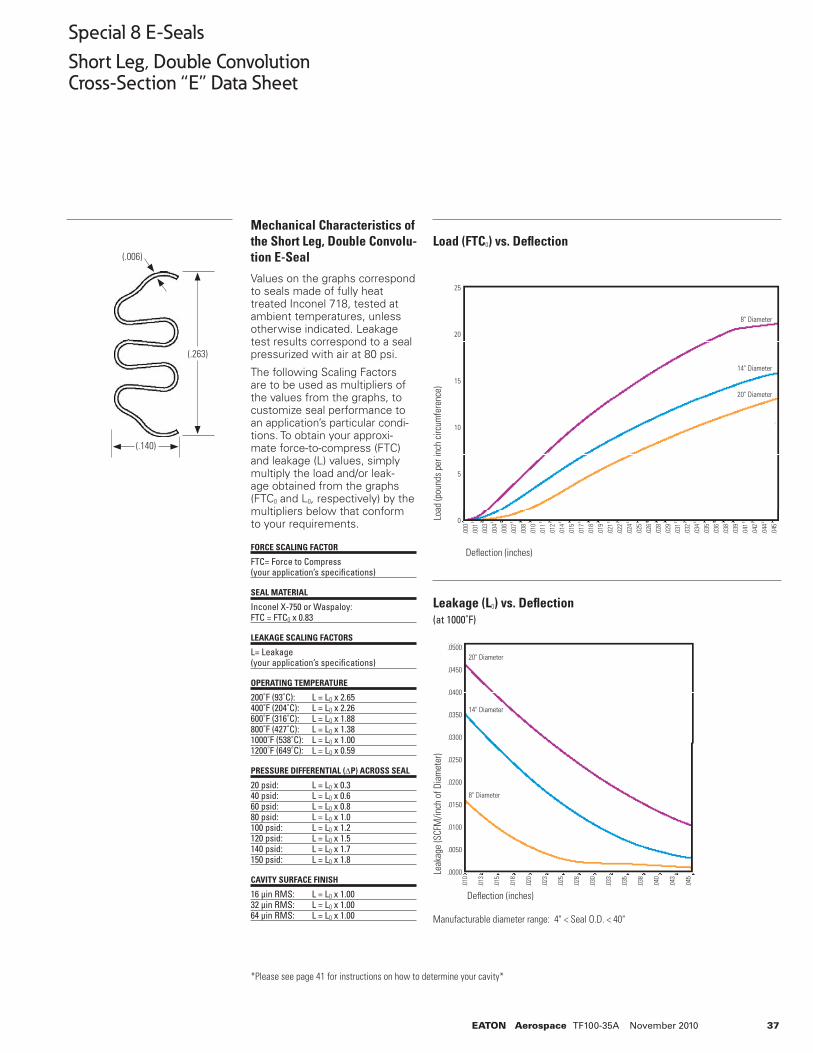
37EATON Aerospace TF100-35A November 2010
Special 8 E-Seals
Short Leg, Double ConvolutionCross-Section “E” Data Sheet
Manufacturable diameter range: 4" < Seal O.D. < 40"
*Please see page 41 for instructions on how to determine your cavity*
Load (FTC0) vs. Defl ection
Leakage (L0) vs. Defl ection(at 1000˚F)
Defl ection (inches)
Defl ection (inches)
(.006)
(.140)
(.263)
Load
(pou
nds
per i
nch
circ
umfe
renc
e) Le
akag
e (S
CFM
/inch
of D
iam
eter
)
Mechanical Characteristics of the Short Leg, Double Convolu-tion E-Seal
Values on the graphs correspond to seals made of fully heat treated Inconel 718, tested at ambient temperatures, unless otherwise indicated. Leakage test results correspond to a seal pressurized with air at 80 psi.
The following Scaling Factors are to be used as multipliers of the values from the graphs, to customize seal performance to an application’s particular condi-tions. To obtain your approxi-mate force-to-compress (FTC) and leakage (L) values, simply multiply the load and/or leak-age obtained from the graphs (FTC0 and L0, respectively) by the multipliers below that conform to your requirements.
FORCE SCALING FACTOR
FTC= Force to Compress(your application’s specifi cations)
SEAL MATERIAL
Inconel X-750 or Waspaloy:FTC = FTC0 x 0.83
LEAKAGE SCALING FACTORS
L= Leakage(your application’s specifi cations)
OPERATING TEMPERATURE
200˚F (93˚C): L = L0 x 2.65400˚F (204˚C): L = L0 x 2.26600˚F (316˚C): L = L0 x 1.88800˚F (427˚C): L = L0 x 1.381000˚F (538˚C): L = L0 x 1.001200˚F (649˚C): L = L0 x 0.59
PRESSURE DIFFERENTIAL (ΔP) ACROSS SEAL
20 psid: L = L0 x 0.340 psid: L = L0 x 0.660 psid: L = L0 x 0.880 psid: L = L0 x 1.0100 psid: L = L0 x 1.2120 psid: L = L0 x 1.5140 psid: L = L0 x 1.7150 psid: L = L0 x 1.8
CAVITY SURFACE FINISH
16 µin RMS: L = L0 x 1.0032 µin RMS: L = L0 x 1.0064 µin RMS: L = L0 x 1.00
.000
.001
.003
.004
.006
.007
.008
.010
.011
.012
.014
.015
.017
.018
.019
.021
.022
.024
.025
.026
.028
.029
.031
.032
.034
.035
.036
.038
.039
.041
.042
.044
.045
20" Diameter
.0500
.0450
.0400
.0350
.0300
.0250
.0200
.0150
.0100
.0050
.0000
.010
.013
.015
.018
.020
.023
.025
.028
.030
.033
.035
.038
.040
.043
.045
20" Diameter
14" Diameter
8" Diameter
25
20
15
10
5
0
8" Diameter
14" Diameter
20" Diameter
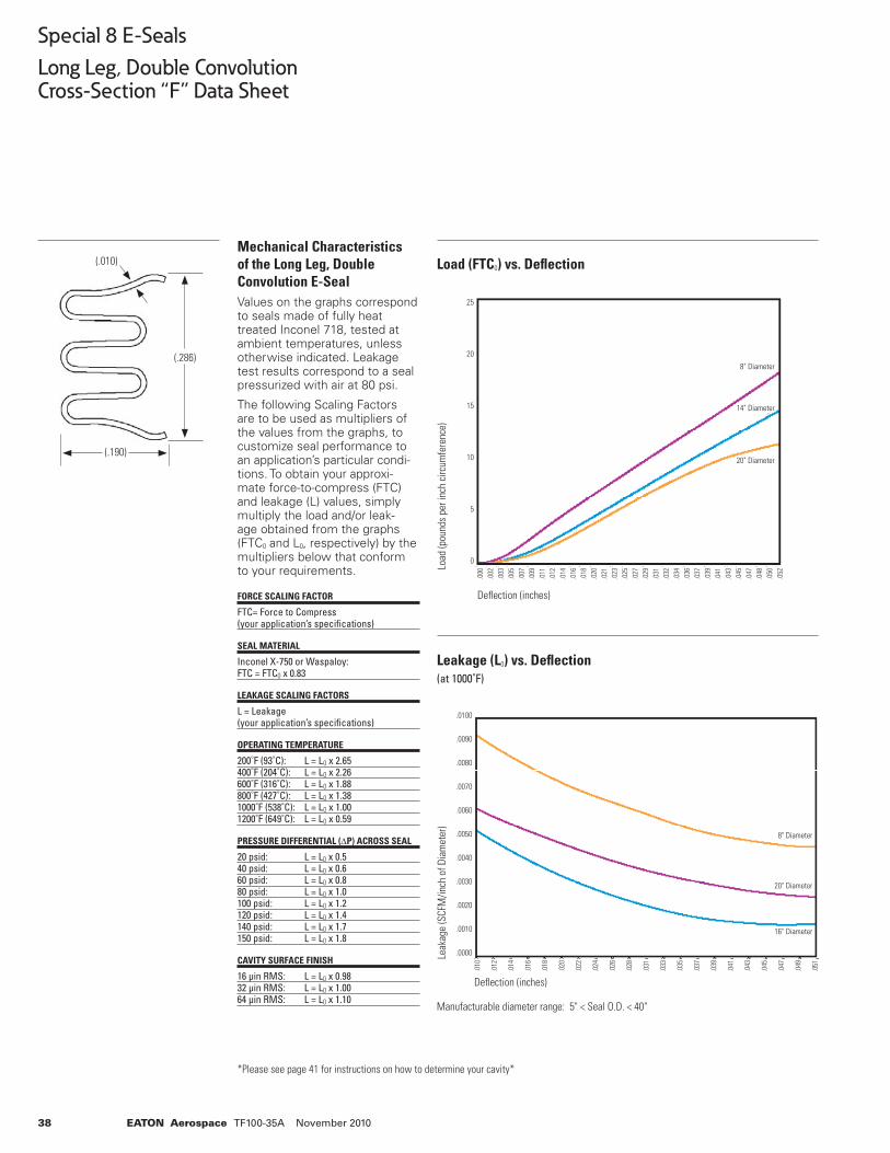
38 EATON Aerospace TF100-35A November 2010
Special 8 E-Seals
Long Leg, Double ConvolutionCross-Section “F” Data Sheet
Mechanical Characteristics of the Long Leg, Double Convolution E-Seal Values on the graphs correspond to seals made of fully heat treated Inconel 718, tested at ambient temperatures, unless otherwise indicated. Leakage test results correspond to a seal pressurized with air at 80 psi.
The following Scaling Factors are to be used as multipliers of the values from the graphs, to customize seal performance to an application’s particular condi-tions. To obtain your approxi-mate force-to-compress (FTC) and leakage (L) values, simply multiply the load and/or leak-age obtained from the graphs (FTC0 and L0, respectively) by the multipliers below that conform to your requirements.
FORCE SCALING FACTOR
FTC= Force to Compress(your application’s specifi cations)
SEAL MATERIAL
Inconel X-750 or Waspaloy:FTC = FTC0 x 0.83
LEAKAGE SCALING FACTORS
L = Leakage(your application’s specifi cations)
OPERATING TEMPERATURE
200˚F (93˚C): L = L0 x 2.65400˚F (204˚C): L = L0 x 2.26600˚F (316˚C): L = L0 x 1.88800˚F (427˚C): L = L0 x 1.381000˚F (538˚C): L = L0 x 1.001200˚F (649˚C): L = L0 x 0.59
PRESSURE DIFFERENTIAL (ΔP) ACROSS SEAL
20 psid: L = L0 x 0.540 psid: L = L0 x 0.660 psid: L = L0 x 0.880 psid: L = L0 x 1.0100 psid: L = L0 x 1.2120 psid: L = L0 x 1.4140 psid: L = L0 x 1.7150 psid: L = L0 x 1.8
CAVITY SURFACE FINISH
16 µin RMS: L = L0 x 0.9832 µin RMS: L = L0 x 1.0064 µin RMS: L = L0 x 1.10
Manufacturable diameter range: 5" < Seal O.D. < 40"
*Please see page 41 for instructions on how to determine your cavity*
Load (FTC0) vs. Defl ection
Leakage (L0) vs. Defl ection(at 1000˚F)
Load
(pou
nds
per i
nch
circ
umfe
renc
e) Le
akag
e (S
CFM
/inch
of D
iam
eter
)
Defl ection (inches)
(.010)
(.190)
(.286)
.0100
.0090
.0080
.0070
.0060
.0050
.0040
.0030
.0020
.0010
.0000
.010
.012
.014
.016
.018
.020
.022
.024
.026
.028
.031
.033
.035
.037
.039
.041
.043
.045
.047
.049
.051
8" Diameter
20" Diameter
16" Diameter
8" Diameter
14" Diameter
20" Diameter
25
20
15
10
5
0
.000
.002
.003
.005
.007
.009
.011
.012
.014
.016
.018
.020
.021
.023
.025
.027
.029
.031
.032
.034
.036
.037
.039
.041
.043
.045
.047
.048
.050
.0
52
Defl ection (inches)
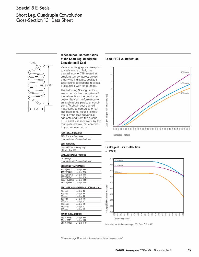
39EATON Aerospace TF100-35A November 2010
Special 8 E-Seals
Short Leg, Quadruple ConvolutionCross-Section “G” Data Sheet
Manufacturable diameter range: 7" < Seal O.D. < 40"
*Please see page 41 for instructions on how to determine your cavity*
Load (FTC0) vs. Defl ection
Leakage (L0) vs. Defl ection(at 1000˚F)
Defl ection (inches)
Defl ection (inches)
(.010)
(.135)
(.3235)
Load
(pou
nds
per i
nch
circ
umfe
renc
e) Le
akag
e (S
CFM
/inch
of D
iam
eter
)
Mechanical Characteristics of the Short Leg, Quadruple Convolution E-SealValues on the graphs correspond to seals made of fully heat treated Inconel 718, tested at ambient temperatures, unless otherwise indicated. Leakage test results correspond to a seal pressurized with air at 80 psi.
The following Scaling Factors are to be used as multipliers of the values from the graphs, to customize seal performance to an application’s particular condi-tions. To obtain your approxi-mate force-to-compress (FTC) and leakage (L) values, simply multiply the load and/or leak-age obtained from the graphs (FTC0 and L0, respectively) by the multipliers below that conform to your requirements.
FORCE SCALING FACTOR
FTC= Force to Compress(your application’s specifi cations)
SEAL MATERIAL
Inconel X-750 or Waspaloy:FTC = FTC0 x 0.83
LEAKAGE SCALING FACTORS
L= Leakage(your application’s specifi cations)
OPERATING TEMPERATURE
200˚F (93˚C): L = L0 x 2.65400˚F (204˚C): L = L0 x 2.26600˚F (316˚C): L = L0 x 1.88800˚F (427˚C): L = L0 x 1.381000˚F (538˚C): L = L0 x 1.001200˚F (649˚C): L = L0 x 0.59
PRESSURE DIFFERENTIAL (ΔP) ACROSS SEAL
20 psid: L = L0 x 0.340 psid: L = L0 x 0.560 psid: L = L0 x 0.880 psid: L = L0 x 1.0100 psid: L = L0 x 1.2120 psid: L = L0 x 1.5140 psid: L = L0 x 1.7150 psid: L = L0 x 1.9
CAVITY SURFACE FINISH
16 µin RMS: L = L0 x 0.9832 µin RMS: L = L0 x 1.0064 µin RMS: L = L0 x 1.10
40
35
30
25
20
15
10
5
0
.000
.002
.004
.005
.007
.009
.011
.013
.015
.017
.019
.021
.023
.025
.026
.028
.030
.032
.034
.036
.038
.040
.042
.044
.046
.047
.049
.051
.053
.055
.057
.059
.0090
.0080
.0070
.0060
.0050
.0040
.0030
.0020
.0010
.0000
.010
.012
.015
.017
.019
.022
.024
.026
.028
.031
.033
.035
.038
.040
.042
.045
.047
.049
.051
.054
.056
8" Diameter
14" Diameter
20" Diameter
8" Diameter
14" Diameter
20" Diameter
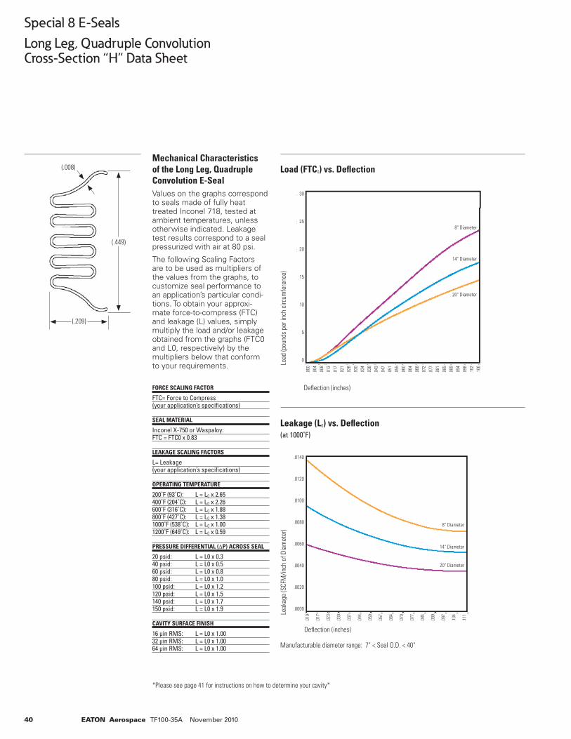
40 EATON Aerospace TF100-35A November 2010
Special 8 E-Seals
Long Leg, Quadruple ConvolutionCross-Section “H” Data Sheet
Mechanical Characteristics of the Long Leg, Quadruple Convolution E-Seal Values on the graphs correspond to seals made of fully heat treated Inconel 718, tested at ambient temperatures, unless otherwise indicated. Leakage test results correspond to a seal pressurized with air at 80 psi.
The following Scaling Factors are to be used as multipliers of the values from the graphs, to customize seal performance to an application’s particular condi-tions. To obtain your approxi-mate force-to-compress (FTC) and leakage (L) values, simply multiply the load and/or leakage obtained from the graphs (FTC0 and L0, respectively) by the multipliers below that conform to your requirements.
FORCE SCALING FACTOR
FTC= Force to Compress(your application’s specifi cations)
SEAL MATERIAL
Inconel X-750 or Waspaloy:FTC = FTC0 x 0.83
LEAKAGE SCALING FACTORS
L= Leakage(your application’s specifi cations)
OPERATING TEMPERATURE
200˚F (93˚C): L = L0 x 2.65400˚F (204˚C): L = L0 x 2.26600˚F (316˚C): L = L0 x 1.88800˚F (427˚C): L = L0 x 1.381000˚F (538˚C): L = L0 x 1.001200˚F (649˚C): L = L0 x 0.59
PRESSURE DIFFERENTIAL (ΔP) ACROSS SEAL
20 psid: L = L0 x 0.340 psid: L = L0 x 0.560 psid: L = L0 x 0.880 psid: L = L0 x 1.0100 psid: L = L0 x 1.2120 psid: L = L0 x 1.5140 psid: L = L0 x 1.7150 psid: L = L0 x 1.9
CAVITY SURFACE FINISH
16 µin RMS: L = L0 x 1.0032 µin RMS: L = L0 x 1.0064 µin RMS: L = L0 x 1.00 Manufacturable diameter range: 7" < Seal O.D. < 40"
*Please see page 41 for instructions on how to determine your cavity*
Load (FTC0) vs. Defl ection
Leakage (L0) vs. Defl ection(at 1000˚F)
Load
(pou
nds
per i
nch
circ
umfe
renc
e)
Defl ection (inches)
Leak
age
(SCF
M/in
ch o
f Dia
met
er)
Defl ection (inches)
(.008)
(.209)
(.449)
30
25
20
15
10
5
0
.000
.004
.008
.013
.017
.021
.026
.030
.034
.038
.043
.047
.051
.055
.060
.064
.068
.072
.077
.081
.085
.089
.094
.098
.102
.106
8" Diameter
14" Diameter
20" Diameter
8" Diameter
14" Diameter
20" Diameter
.0140
.0120
.0100
.0080
.0060
.0040
.0020
.0000
.010
.017
.023
.030
.037
.044
.050
.057
.064
.070
.077
.084
.090
.097
.104
.111
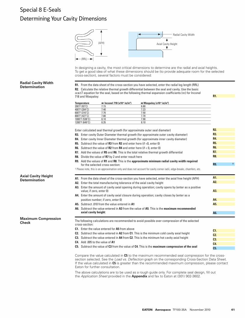
41EATON Aerospace TF100-35A November 2010
88
Special 8 E-Seals
Determining Your Cavity Dimensions
In designing a cavity, the most critical dimensions to determine are the radial and axial heights. To get a good idea of what these dimensions should be (to provide adequate room for the selected cross-section), several factors must be considered:
R1. From the data sheet of the cross-section you have selected, enter the radial leg length (RRL)R2. Calculate the relative thermal growth differential between the seal and cavity. Use the basic øΔT equation for the seal, based on the following thermal expansion coeffi cients ( ) for Inconel 718 and Waspaloy:
Temperature Inconel 718 (x10-6 in/inº) Waspaloy (x10-6 in/inº) 200˚F (93˚C) 7.15 6.80 400˚F (204˚C) 7.40 7.23 600˚F (316˚C) 7.70 7.50800˚F (427˚C) 7.80 7.701000˚F (538˚C) 8.10 7.901200˚F (649˚C) 8.35 8.10
Enter calculated seal thermal growth (for approximate outer seal diameter)R3. Enter cavity Outer Diameter thermal growth (for approximate outer cavity diameter)R4. Enter cavity Inner Diameter thermal growth (for approximate inner cavity diameter)R5. Subtract the value of R3 from R2 and enter here (if <0, enter 0)R6. Subtract the value of R2 from R4 and enter here (if < 0, enter 0)R7. Add the values of R5 and R6. This is the total relative thermal growth differentialR8. Divide the value of R7 by 2 and enter result hereR9. Add the values of R1 and R8. This is the approximate minimum radial cavity width required for the selected cross-section:† Please note, this is an approximation only and does not account for cavity corner radii, edge-breaks, chamfers, etc.
A1. From the data sheet of the cross-section you have selected, enter the axial free height (AFH)A2. Enter the total manufacturing tolerance of the axial cavity heightA3. Enter the amount of cavity axial opening during operation; cavity opens by (enter as a positive value; if zero, enter 0)A4. Enter the amount of cavity axial closure during operation; cavity closes by (enter as a positive number; if zero, enter 0)A5. Subtract .010 from the value entered in A1A6. Subtract the value entered in A3 from the value of A5. This is the maximum recommended axial cavity height:
The following calculations are recommended to avoid possible over-compression of the selected cross-section:C1. Enter the value entered for A5 from aboveC2. Subtract the value entered in A2 from C1. This is the minimum cold cavity axial heightC3. Subtract the value entered in A4 from C2. This is the minimum hot cavity axial heightC4. Add .005 to the value of A1 C5. Subtract the value of C3 from the value of C4. This is the maximum compression of the seal
Compare the value calculated in C5 to the maximum recommended seal compression for the cross-section selected. See the Load vs. Defl ection graph on the corresponding Cross-Section Data Sheet. If the value calculated in C5 is greater than the recommended maximum compression, please contact Eaton for further consultation.
The above calculations are to be used as a rough guide only. For complete seal design, fi ll out the Application Sheet provided in the Appendix and fax to Eaton at (301) 902-3602.
Radial Cavity Width Determination
Axial Cavity Height Determination
Maximum Compression Check
R1.
R2.R3.R4.R5.R6.R7.R8.
R9. †
A1.A2.
A3.
A4.A5.
A6.
C1.C2.C3.C4.C5.
(AFH)
(RRL)
Radial Cavity Width
Axial Cavity Height
8 8
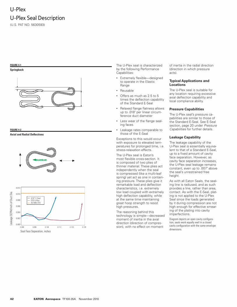
42 EATON Aerospace TF100-35A November 2010
The U-Plex seal is characterized by the following Performance Capabilities:• Extremely fl exible—designed
to operate in the Elastic Range
• Reusable• Offers as much as 2.5 to 5
times the defl ection capability of the Standard E-Seal
• Relaxed fl ange fl atness allows up to .018" per linear circum-ference duct diameter
• Less wear of the fl ange seal-ing faces
• Leakage rates comparable to those of the E-Seal
Exceptions to this would occur with exposure to elevated tem-peratures for prolonged time, i.e. stress-relaxation effects.
The U-Plex seal is Eaton’s most fl exible cross-section. It is composed of two plies of thinner material. These plies act independently when the seal is compressed (like a multi-leaf spring) yet act as one in contain-ing pressure. These plies give it remarkable load and defl ection characteristics, i.e. extremely low load coupled with extremely high defl ection capability, while at the same time maintaining great hoop strength to resist high pressures.
The reasoning behind this technology is simple—decreased moment of inertia in the axial direction (direction of compres-sion), with no effect on moment
of inertia in the radial direction (direction in which pressure acts).
Typical Applications and Locations
The U-Plex seal is suitable for any location requiring excessive axial defl ection capability and local compliance ability.
Pressure Capabilities
The U-Plex seal’s pressure ca-pabilities are similar to those of the Standard E-Seal. See E-Seal section, page 20 under Pressure Capabilities for further details.
Leakage Capability
The leakage capability of the U-Plex seal is essentially equiva-lent to that of a Standard E-Seal, up to a fi xed amount of cavity face separation. However, as cavity face separation increases, the U-Plex seal leakage remains constant, even up to .007" above the seal’s unrestrained free height.
As with all Eaton Seals, the seal-ing line is radiused, and as such provides a line, rather than area, contact. As with the E-Seal, plat-ing is not applied to the U-Plex Seal since the loads generated by it during compression are not high enough for effective smear-ing of the plating into cavity imperfections.Diagram depicts an open cavity confi gura-tion; seals work equally well in a closed cavity confi guration with the same envelope dimensions.
FIGURE 4-1
Springback
FIGURE 4-2
Axial and Radial Defl ections
U-Plex
U-Plex Seal Description(U.S. PAT NO. 5630593)
Leak
age
SCFM
/inch
of D
uct D
ia.
0.012
0.010
0.008
0.006
0.004
0.002
.0.000 0.088 0.096 0.104 0.112 0.120 0.128
Seal Face Separation, inches
3/32" E-SealSTD U-PlexAS1895 STD
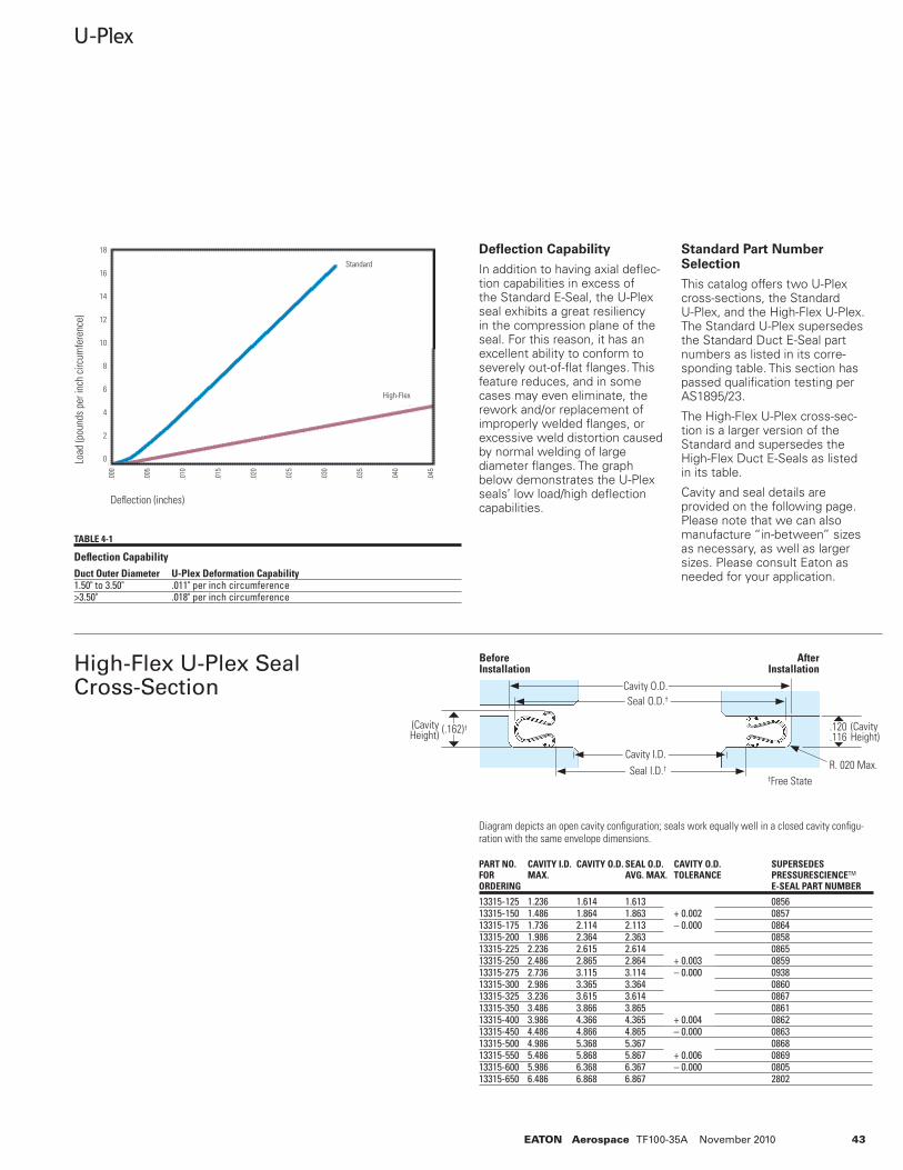
43EATON Aerospace TF100-35A November 2010
Diagram depicts an open cavity confi guration; seals work equally well in a closed cavity confi gu-ration with the same envelope dimensions.
U-Plex
13315-125 1.236 1.614 1.613 085613315-150 1.486 1.864 1.863 + 0.002 085713315-175 1.736 2.114 2.113 – 0.000 086413315-200 1.986 2.364 2.363 085813315-225 2.236 2.615 2.614 086513315-250 2.486 2.865 2.864 + 0.003 085913315-275 2.736 3.115 3.114 – 0.000 093813315-300 2.986 3.365 3.364 086013315-325 3.236 3.615 3.614 086713315-350 3.486 3.866 3.865 086113315-400 3.986 4.366 4.365 + 0.004 086213315-450 4.486 4.866 4.865 – 0.000 086313315-500 4.986 5.368 5.367 086813315-550 5.486 5.868 5.867 + 0.006 086913315-600 5.986 6.368 6.367 – 0.000 080513315-650 6.486 6.868 6.867 2802
PART NO. CAVITY I.D. CAVITY O.D. SEAL O.D. CAVITY O.D. SUPERSEDESFOR MAX. AVG. MAX. TOLERANCE PRESSURESCIENCETM
ORDERING E-SEAL PART NUMBER
Defl ection Capability
In addition to having axial defl ec-tion capabilities in excess of the Standard E-Seal, the U-Plex seal exhibits a great resiliency in the compression plane of the seal. For this reason, it has an excellent ability to conform to severely out-of-fl at fl anges. This feature reduces, and in some cases may even eliminate, the rework and/or replacement of improperly welded fl anges, or excessive weld distortion caused by normal welding of large diameter fl anges. The graph below demonstrates the U-Plex seals’ low load/high defl ection capabilities.
Standard Part Number Selection
This catalog offers two U-Plex cross-sections, the Standard U-Plex, and the High-Flex U-Plex. The Standard U-Plex supersedes the Standard Duct E-Seal part numbers as listed in its corre-sponding table. This section has passed qualifi cation testing per AS1895/23.
The High-Flex U-Plex cross-sec-tion is a larger version of the Standard and supersedes the High-Flex Duct E-Seals as listed in its table.
Cavity and seal details are provided on the following page. Please note that we can also manufacture “in-between” sizes as necessary, as well as larger sizes. Please consult Eaton as needed for your application.
High-Flex U-Plex Seal Cross-Section
TABLE 4-1
Defl ection CapabilityDuct Outer Diameter U-Plex Deformation Capability1.50" to 3.50" .011" per inch circumference>3.50" .018" per inch circumference
Defl ection (inches)
Load
(pou
nds
per i
nch
circ
umfe
renc
e)
.120
.116(Cavity Height)
(.162)†(Cavity Height)
Cavity O.D.Seal O.D.†
†Free State
Cavity I.D.Seal I.D.† R. 020 Max.
Before Installation
After Installation
18
16
14
12
10
8
6
4
2
0
.000
.005
.010
.015
.020
.025
.030
.035
.040
.045
Standard
High-Flex
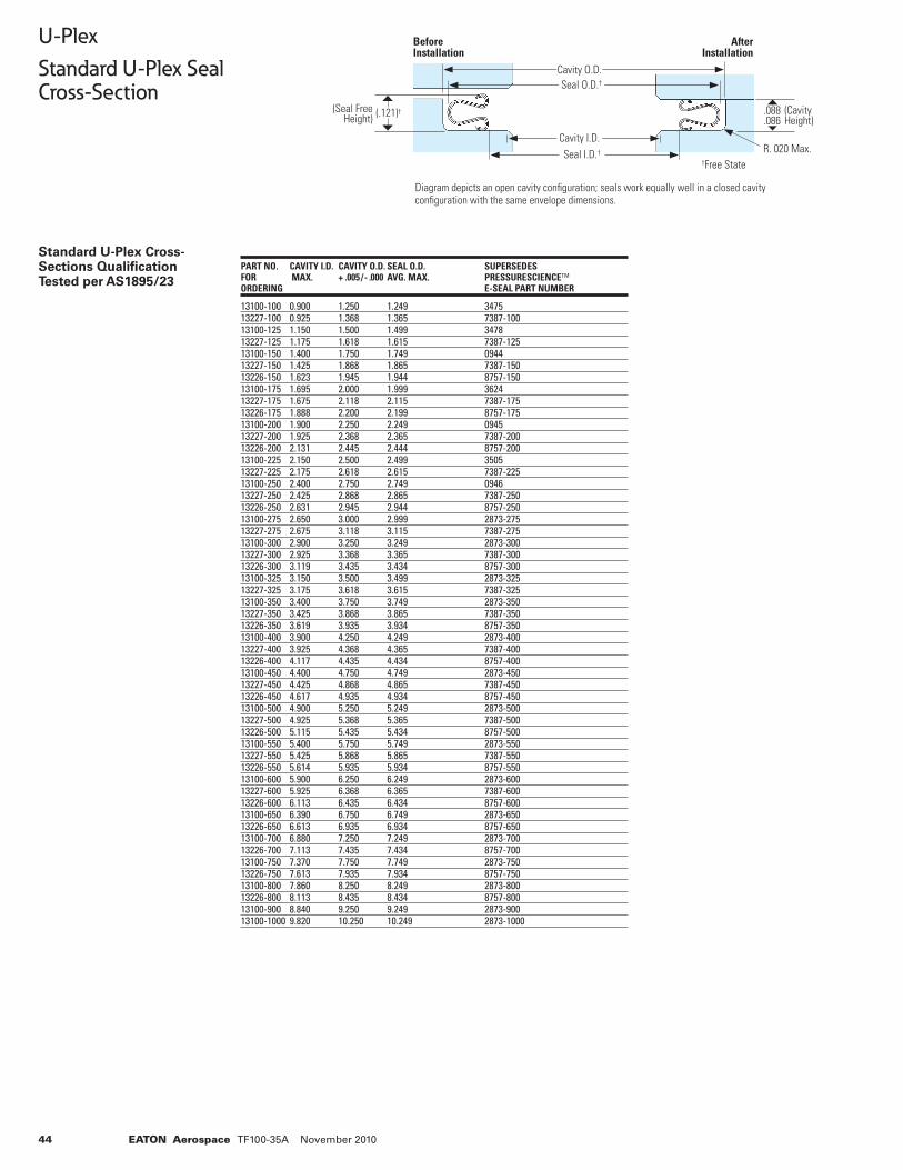
44 EATON Aerospace TF100-35A November 2010
13100-100 0.900 1.250 1.249 3475 13227-100 0.925 1.368 1.365 7387-100 13100-125 1.150 1.500 1.499 3478 13227-125 1.175 1.618 1.615 7387-125 13100-150 1.400 1.750 1.749 0944 13227-150 1.425 1.868 1.865 7387-150 13226-150 1.623 1.945 1.944 8757-150 13100-175 1.695 2.000 1.999 3624 13227-175 1.675 2.118 2.115 7387-175 13226-175 1.888 2.200 2.199 8757-175 13100-200 1.900 2.250 2.249 0945 13227-200 1.925 2.368 2.365 7387-200 13226-200 2.131 2.445 2.444 8757-200 13100-225 2.150 2.500 2.499 3505 13227-225 2.175 2.618 2.615 7387-225 13100-250 2.400 2.750 2.749 0946 13227-250 2.425 2.868 2.865 7387-250 13226-250 2.631 2.945 2.944 8757-250 13100-275 2.650 3.000 2.999 2873-275 13227-275 2.675 3.118 3.115 7387-275 13100-300 2.900 3.250 3.249 2873-300 13227-300 2.925 3.368 3.365 7387-300 13226-300 3.119 3.435 3.434 8757-300 13100-325 3.150 3.500 3.499 2873-325 13227-325 3.175 3.618 3.615 7387-325 13100-350 3.400 3.750 3.749 2873-350 13227-350 3.425 3.868 3.865 7387-350 13226-350 3.619 3.935 3.934 8757-350 13100-400 3.900 4.250 4.249 2873-400 13227-400 3.925 4.368 4.365 7387-400 13226-400 4.117 4.435 4.434 8757-400 13100-450 4.400 4.750 4.749 2873-450 13227-450 4.425 4.868 4.865 7387-450 13226-450 4.617 4.935 4.934 8757-450 13100-500 4.900 5.250 5.249 2873-500 13227-500 4.925 5.368 5.365 7387-500 13226-500 5.115 5.435 5.434 8757-500 13100-550 5.400 5.750 5.749 2873-550 13227-550 5.425 5.868 5.865 7387-550 13226-550 5.614 5.935 5.934 8757-550 13100-600 5.900 6.250 6.249 2873-600 13227-600 5.925 6.368 6.365 7387-600 13226-600 6.113 6.435 6.434 8757-600 13100-650 6.390 6.750 6.749 2873-650 13226-650 6.613 6.935 6.934 8757-650 13100-700 6.880 7.250 7.249 2873-700 13226-700 7.113 7.435 7.434 8757-700 13100-750 7.370 7.750 7.749 2873-750 13226-750 7.613 7.935 7.934 8757-750 13100-800 7.860 8.250 8.249 2873-800 13226-800 8.113 8.435 8.434 8757-800 13100-900 8.840 9.250 9.249 2873-900 13100-1000 9.820 10.250 10.249 2873-1000
PART NO. CAVITY I.D. CAVITY O.D. SEAL O.D. SUPERSEDES FOR MAX. + .005 / - .000 AVG. MAX. PRESSURESCIENCETM
ORDERING E-SEAL PART NUMBER
Standard U-Plex Cross-Sections Qualifi cation Tested per AS1895/23
Diagram depicts an open cavity confi guration; seals work equally well in a closed cavity confi guration with the same envelope dimensions.
†Free State
.088
.086(Cavity Height)
(.121)†(Seal Free Height)
Cavity O.D.Seal O.D.†
Cavity I.D.Seal I.D.† R. 020 Max.
Before Installation
After Installation
U-Plex
Standard U-Plex SealCross-Section
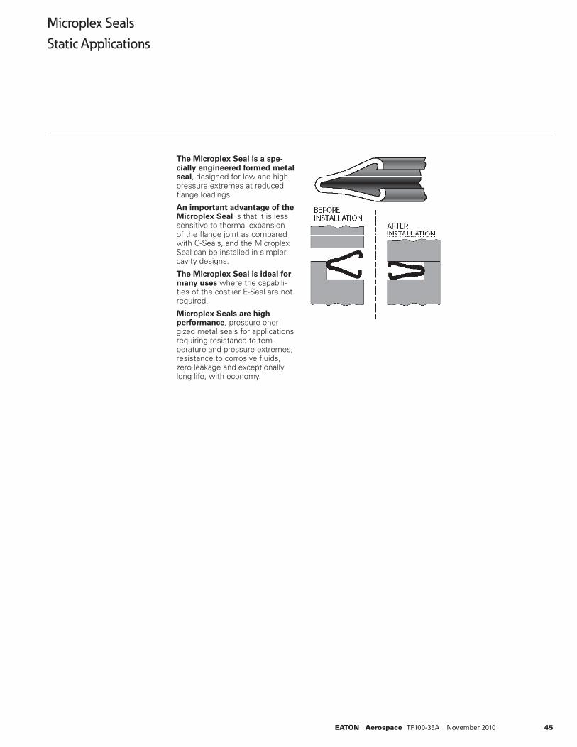
45EATON Aerospace TF100-35A November 2010
The Microplex Seal is a spe-cially engineered formed metal seal, designed for low and high pressure extremes at reduced fl ange loadings.
An important advantage of the Microplex Seal is that it is less sensitive to thermal expansion of the fl ange joint as compared with C-Seals, and the Microplex Seal can be installed in simpler cavity designs.
The Microplex Seal is ideal for many uses where the capabili-ties of the costlier E-Seal are not required.
Microplex Seals are high performance, pressure-ener-gized metal seals for applications requiring resistance to tem-perature and pressure extremes, resistance to corrosive fl uids, zero leakage and exceptionally long life, with economy.
Microplex Seals
Static Applications
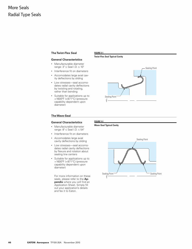
46 EATON Aerospace TF100-35A November 2010
The Twist-Flex Seal
General Characteristics
• Manufacturable diameter range: 3" ≤ Seal I.D. ≤ 10"
• Interference fi t on diameters• Accomodates large axial cav-
ity defl ections by sliding• Low stresses—seal accomo-
dates radial cavity defl ections by twisting and rotating, rather than bending
• Suitable for applications up to +1600ºF (+871°C) (pressure capability dependent upon diameter)
The Wave-Seal
General Characteristics
• Manufacturable diameter range: 8" ≤ Seal I.D. ≤ 54"
• Interference fi t on diameters• Accomodates large axial
cavity defl ections by sliding• Low stresses—seal accomo-
dates radial cavity defl ections by fl exure and rotation about sealing line centers
• Suitable for applications up to +1600ºF (+871°C) (pressure capability dependent upon diameter)
For more information on these seals, please refer to the Ap-pendix where you will fi nd an Application Sheet. Simply fi ll out your application’s details and fax it to Eaton.
More Seals
Radial Type Seals
FIGURE 5-1
Twist-Flex Seal Typical Cavity
FIGURE 5-2
Wave-Seal Typical Cavity
C L
Sealing Point
Sealing Point
C LSealing Point
Sealing Point
Sealing Point
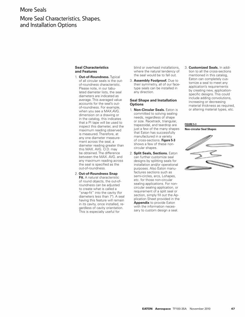
47EATON Aerospace TF100-35A November 2010
Seal Characteristics and Features
1. Out-of-Roundness. Typical of all circular seals is the out-of-roundness characteristic. Please note, in our tabu-lated diameter lists, the seal diameters are indicated as average. This averaged value accounts for the seal’s out-of-roundness. For example, when you see a MAX.AVG. dimension on a drawing or in the catalog, this indicates that a PI tape will be used to inspect this diameter, and the maximum reading observed is measured. Therefore, at any one diameter measure-ment across the seal, a diameter reading greater than this MAX. AVG. O.D. may be obtained. The difference between the MAX. AVG. and any maximum reading across the seal is specifi ed as the out-of-roundness.
2. Out-of-Roundness Snap Fit. A natural characteristic of round objects, the out-of-roundness can be adjusted to create what is called a “snap-fi t” into the cavity (for diameters less than 7"). A seal having this feature will remain in its cavity, once installed, re-gardless of cavity orientation. This is especially useful for
blind or overhead installations, where the natural tendency of the seal would be to fall out.
3. Assembly Foolproof. Due to their symmetry, all of our face-type seals can be installed in any direction.
Seal Shape and Installation Options
1. Non-Circular Seals. Eaton is committed to solving sealing needs, regardless of shape or size. Racetrack, triangular, trapezoidal, and teardrop are just a few of the many shapes that Eaton has successfully manufactured in a variety of cross-sections. Figure 5-3 shows a few of these non-circular shapes.
2. Split Seals, Sections. Eaton can further customize seal designs by splitting seals for installation and/or operational purposes. Also Eaton manu-factures sections such as semi-circles, arcs, L-shapes, etc. for those non-circular sealing applications. For non-circular sealing application, or requirement of a split seal or section, simply fi ll out the Ap-plication Sheet provided in the Appendix to provide Eaton with the information neces-sary to custom design a seal.
3. Customized Seals. In addi-tion to all the cross-sections mentioned in this catalog, Eaton can completely cus-tomize a seal to meet any application’s requirements by creating new, application-specifi c designs. This could include adding convolutions, increasing or decreasing material thickness as required, or altering material types, etc.
FIGURE 5-3
Non-circular Seal Shapes
More Seals
More Seal Characteristics, Shapes, and Installation Options
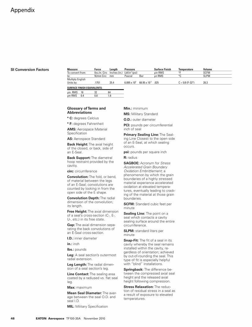
48 EATON Aerospace TF100-35A November 2010
Appendix
SI Conversion Factors
Glossary of Terms and Abbreviations
° C: degrees Celcius
° F: degrees Fahrenheit
AMS: Aerospace Material Specifi cation
AS: Aerospace Standard
Back Height: The axial height of the closed, or back, side of an E-Seal.
Back Support: The diametral hoop restraint provided by the cavitiy.
circ: circumference
Convolution: The fold, or bend, of material between the legs of an E-Seal; convolutions are counted by looking in from the open side of the E shape.
Convolution Depth: The radial dimension of the convolution; its length.
Free Height: The axial dimension of a seal’s cross-section (C-, E-, U-, etc.) in its free state.
Gap: The axial dimension sepa-rating the back convolutions of an E-Seal cross-section.
I.D.: inner diameter
in.: inch
lbs.: pounds
Leg: A seal section’s outermost radial extension.
Leg Length: The radial dimen-sion of a seal section’s leg.
Line Contact: The sealing area coated by a radiused vs. fl at seal leg.
Max: maximum
Mean Seal Diameter: The aver-age between the seal O.D. and seal I.D.
MIL: Military Specifi cation
Min.: minimum
MS: Military Standard
O.D.: outer diameter
PCI: pounds per circumferential inch of seal
Primary Sealing Line: The Seal-ing Line Closest to the open side of an E-Seal, at which sealing occurs.
psi: pounds per square inch
R: radius
SAGBOE: Acronym for Stress Accelerated Grain Boundary Oxidation Embrittlement; a phenomenon by which the grain boundaries of a highly stressed material experience accelerated oxidation at elevated tempera-tures, eventually leading to crack-ing of the material at those grain boundaries.
SCFM: Standard cubic feet per minute
Sealing Line: The point on a seal which contacts a cavity sealing surface around the entire circumference.
SLPM: standard liters per minute
Snap-Fit: The fi t of a seal in its cavity whereby the seal remains installed within the cavity, re-gardless of orientation; achieved by out-of-rounding the seal. This type of fi t is especially helpful with “blind” installations.
Springback: The difference be-tween the compressed axial seal height and the released axial height following compression.
Stress Relaxation: The reduc-tion of residual stress in a seal as a result of exposure to elevated temperatures.
Measure Force Length Pressure Surface Finish Temperature VolumeTo convert from: lbs./in. Circ Inches (in.) Lbf/in2 (psi) µin RMS °F SCFMto: N/mm Circ mm Pascal Bar µn RMS °C SLPMMulitply English Units by: .1751 25.4 6.895 x 10³ 68.95 x 10⁻³ .025 C = 5/9 (F-32°) 28.3
SURFACE FINISH EQUIVALENTS:
µin. RMS 16 32 64µm RMS 0.4 0.8 1.6
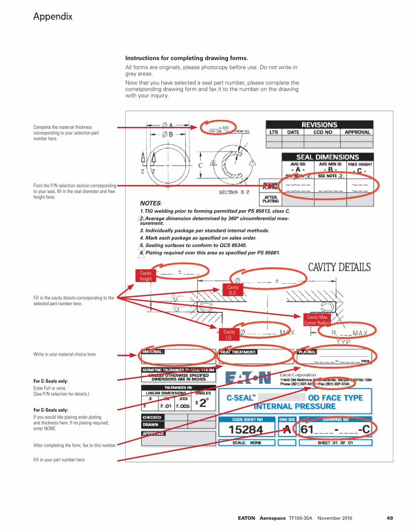
49EATON Aerospace TF100-35A November 2010
Appendix
Instructions for completing drawing forms.
All forms are originals, please photocopy before use. Do not write in grey areas.
Now that you have selected a seal part number, please complete the corresponding drawing form and fax it to the number on the drawing with your inquiry.
Complete the material thickness corresponding to your selection part number here.
From the P/N selection section corresponding to your seal, fi ll in the seal diameter and free height here.
Fill in the cavity details corresponding to the selected part number here.
Write in your material choice here.
For C-Seals only: Enter Full or none. (See P/N selection for details.)
For C-Seals only: If you would like plating enter plating and thickness here. If no plating required, enter NONE.
After completing the form, fax to this number.
Fill in your part number here.
Cavity Height
Cavity O.D.
Cavity I.D.
Cavity MaxCorner Radius
NOTES:
1. TIG welding prior to forming permitted per PS 85613, class C.
2. Average dimension determined by 360° circumferential mea-surement.
3. Individually package per standard internal methods.
4. Mark each package as specifi ed on sales order.
5. Sealing surfaces to conform to QCS 85345.
6. Plating required over this area as specifi ed per PS 85681.
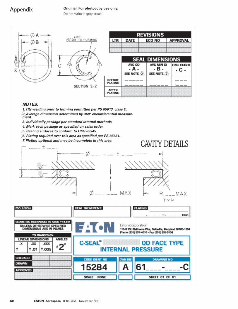
50 EATON Aerospace TF100-35A November 2010
Appendix Original. For photocopy use only.
Do not write in grey areas.
NOTES:1. TIG welding prior to forming permitted per PS 85613, class C.
2. Average dimension determined by 360° circumferential measure-ment.
3. Individually package per standard internal methods.
4. Mark each package as specifi ed on sales order.
5. Sealing surfaces to conform to QCS 85345.
6. Plating required over this area as specifi ed per PS 85681.
7. Plating optional and may be incomplete in this area.
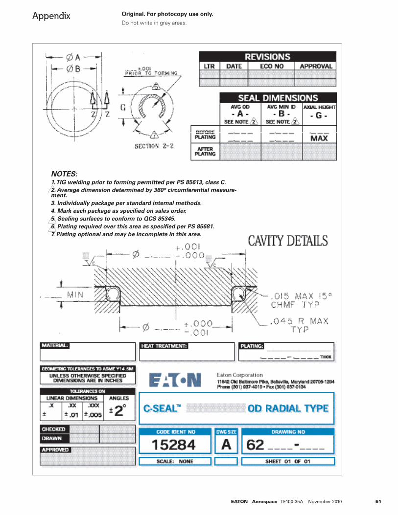
51EATON Aerospace TF100-35A November 2010
Appendix Original. For photocopy use only.
Do not write in grey areas.
NOTES:1. TIG welding prior to forming permitted per PS 85613, class C.
2. Average dimension determined by 360° circumferential measure-ment.
3. Individually package per standard internal methods.
4. Mark each package as specifi ed on sales order.
5. Sealing surfaces to conform to QCS 85345.
6. Plating required over this area as specifi ed per PS 85681.
7. Plating optional and may be incomplete in this area.
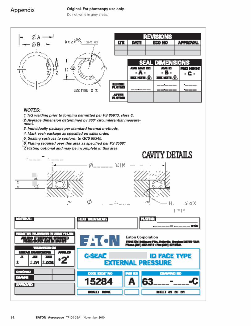
52 EATON Aerospace TF100-35A November 2010
Appendix Original. For photocopy use only.
Do not write in grey areas.
NOTES:1. TIG welding prior to forming permitted per PS 85613, class C.
2. Average dimension determined by 360° circumferential measure-ment.
3. Individually package per standard internal methods.
4. Mark each package as specifi ed on sales order.
5. Sealing surfaces to conform to QCS 85345.
6. Plating required over this area as specifi ed per PS 85681.
7. Plating optional and may be incomplete in this area.
Eaton Corporation
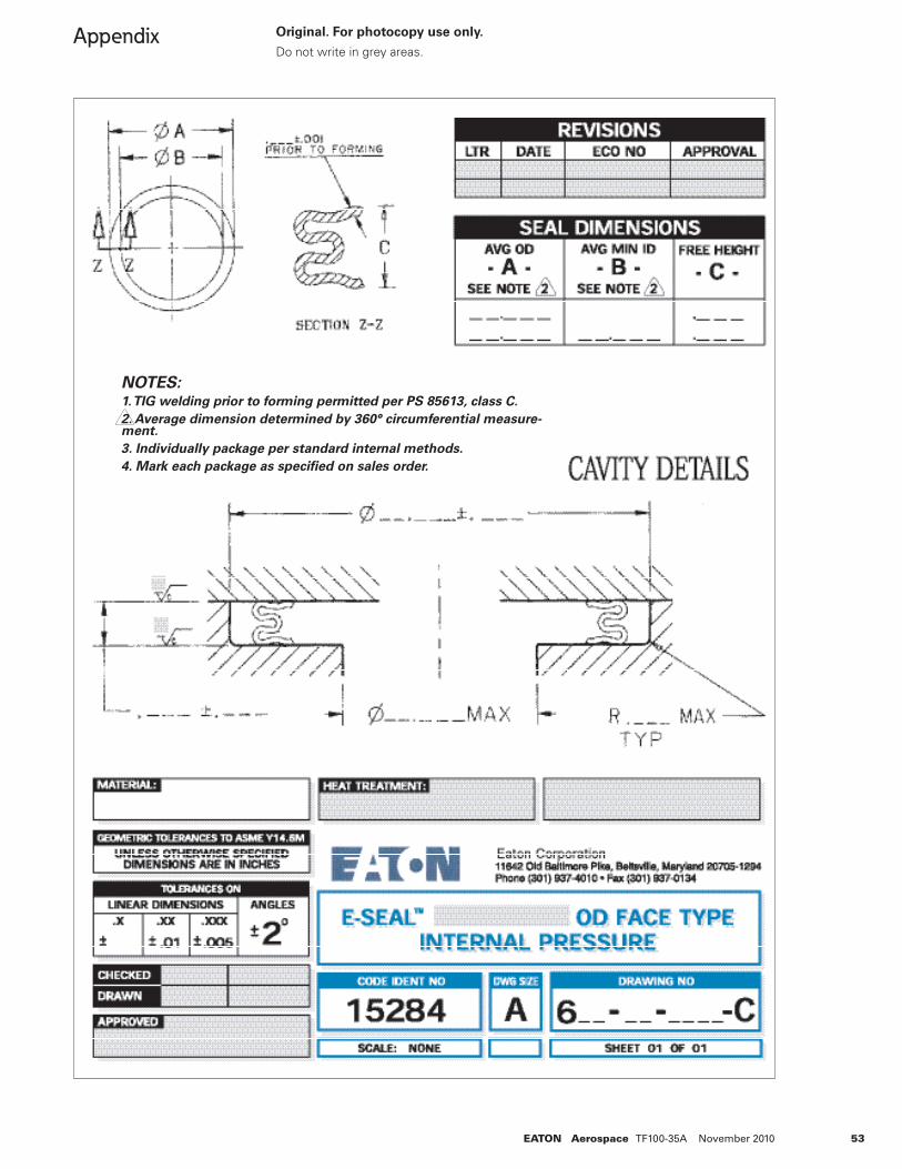
53EATON Aerospace TF100-35A November 2010
Appendix Original. For photocopy use only.
Do not write in grey areas.
NOTES:1. TIG welding prior to forming permitted per PS 85613, class C.
2. Average dimension determined by 360° circumferential measure-ment.
3. Individually package per standard internal methods.
4. Mark each package as specifi ed on sales order.
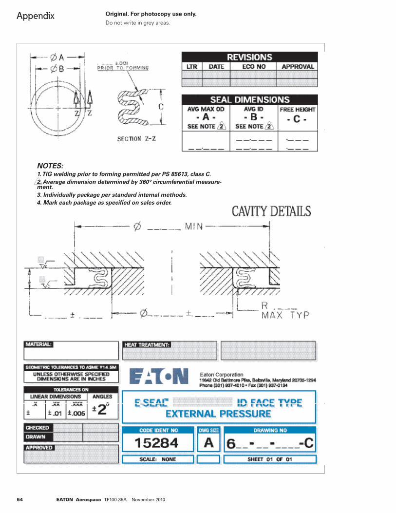
54 EATON Aerospace TF100-35A November 2010
Appendix Original. For photocopy use only.
Do not write in grey areas.
NOTES:1. TIG welding prior to forming permitted per PS 85613, class C.
2. Average dimension determined by 360° circumferential measure-ment.
3. Individually package per standard internal methods.
4. Mark each package as specifi ed on sales order.
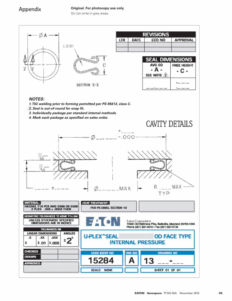
55EATON Aerospace TF100-35A November 2010
Appendix Original. For photocopy use only.
Do not write in grey areas.
NOTES:1. TIG welding prior to forming permitted per PS 85613, class C.
2. Seal is out-of-round for snap fi t.
3. Individually package per standard internal methods.
4. Mark each package as specifi ed on sales order.
56 EATON Aerospace TF100-35A November 2010
Appendix
Eaton’s Application Sheet
Fax: (301) 902-3602
Email: [email protected]
Use this form if you could not fi nd a seal to meet your application’s requirements or would like further assistance with your application. Send this cover sheet along with the requested supporting information to Eaton at the number above. Please be as detailed as possible.
From:
Name Title
Company and Address (Please include mail stop number if applicable)
Telephone Number Fax Number
Today’s date: Total # of pages being sent
Please provide Eaton with a sketch of your application’s cavity. Be sure to include all known information requested below:
a. Location of the centerline
b. Cavity outer and inner diameters, with manufacturing tolerances (øA, øB)
c. Cavity axial height (F), with manufacturing tolerances
d. Axial and radial thermal excursions or growths. For radial growths, indicate whether this value is radial or diametral, and include mechanical effects.
e. Cavity materials and/or thermal expansion coeffi cients
f. Possible sealing surfaces and corresponding allowable load-to-compress requirements and/or limitations.
g. Maximum cavity corner radii, chamfers, and edgebreaks (R. MAX., etc.)
h. Cavity surface fi nish (all mating surfaces)
i. Sealing medium. Indicate values and locations of high and low pressures.
j. Maximum operating temperature. If temperature is greater than 1300ºF, indicate total time spent above 1300º.
k. Expected and/or required life in hours or cycles. (If possible, both.)
l. Leakage requirements (if known)
Original. For photocopy use only.

© 2010 Eaton CorporationAll Rights ReservedPrinted in USAForm No. TF100-35ANovember 2010
EatonAerospace Group9650 Jeronimo RoadIrvine, California 92618Ph (949) 452 9500Fax (949) 452 9555www.eaton.com/aerospace
EatonAerospace GroupConveyance Systems Division300 South East AvenueJackson, Michigan 49203-1972Phone: (517) 787 8121Fax: (517) 787 5758
EatonAerospace GroupConveyance Systems Division90 Clary ConnectorEastanollee, Georgia 30538Phone: (706) 779 3351Fax: (706) 779 2638
EatonAerospace GroupConveyance Systems Division11642 Old Baltimore PikeBeltsville, Maryland 20705Phone: (301) 937 4010Fax: (301) 937 0134
EatonAerospace GroupConveyance Systems Division15 Pioneer Ave.Warwick, Rhode Island 02888Phone: (401) 781 4700Fax: (401) 785 4614
EatonAerospace GroupConveyance Systems Division9650 Jeronimo RoadIrvine, California 92618Phone: (949) 452 9500Fax: (949) 452 9992
Eaton LimitedAerospace GroupConveyance Systems DivisionBroad Ground RoadLakeside, RedditchWorcestershireB98 8YSUnited KingdomPhone: (44) 1527 517555Fax: (44) 1527 517556
Eaton S. A.Aerospace GroupConveyance Systems Division2 Rue Lavoisier BP 54 78310Coignieres, FrancePhone: (33) 130 69 30 00Fax: (33) 130 69 30 56
Eaton S.AAerospace GroupConveyance Systems Division62 Chemin De Pau64121 Serres-CastetFrancePhone: (33) 559 333 864Fax: (33) 559 333 865
Eaton GmbHAerospace GroupConveyance Systems DivisionRudolf-Diesel-Strasse 882205 GilchingGermanyPhone: 49 (0) 8105 7530Fax: 49 (0) 8105 7555
Vickers Systems Pte LtdAerospace GroupConveyance Systems DivisionLot 512, Jalan Delima,Batamindo Industrial ParkBatam 294533, IndonesiaPhone: (62) 770 611823Fax: (62) 770 611821