35a cutskill - cigweldcigweld.com.au/doclib/manual/cutskill-35a-product-manual.pdf · cutskill™...
TRANSCRIPT

35AMP
1PHASEDC
Art # A-09203
cutskill™
plasma cutting system
35a
Operating manualRev. AA Issue Date: June 30, 2009 Manual # 0-5063Operating Features:

WE APPRECIATE YOUR BUSINESS!CongratulationsonyournewThermalDynamicsproduct.Weareproudtohaveyouasourcustomerandwillstrivetoprovideyouwiththebestserviceandreliabilityintheindustry.Thisproductisbackedbyourextensivewarrantyandworld-wideservicenetwork.Tolocateyournearestdistributororserviceprovidervisitusontheweb atwww.cigweld.com.au (Asia Pacific) www.thermal-dynamics.com (Americas and Europe).
ThisOperatingManualhasbeendesignedtoinstructyouonthecorrectuseandoperationofyourThermalDynamicsproduct.Yoursatisfactionwiththisproductanditssafeoperationisourultimateconcern.Thereforepleasetakethetimetoreadtheentiremanual,especiallytheSafetyPrecautions.Theywillhelpyoutoavoidpo-tentialhazardsthatmayexistwhenworkingwiththisproduct.
YOU ARE IN GOOD COMPANY!The Brand of Choice for Contractors and Fabricators Worldwide.ThermalDynamics isaGlobalBrandofmanualandautomationPlasmaCuttingProductsforThermadyneIndustriesInc.
Wedistinguishourselvesfromourcompetitionthroughmarket-leading, dependable products that have stood the test of time.Weprideourselveson technical innovation, competitiveprices,excellentdelivery,superiorcustomerserviceandtechnicalsupport,togetherwithexcellenceinsalesandmarketingexpertise.
Aboveall,wearecommittedtodevelopingtechnologicallyadvancedproductstoachieveasaferworkingenvironmentwithintheweldingindustry.
PlasmaCuttingPowerSupplyCutSkill™35ASL601Torch™OperatingManualNumber0-5063
Publishedby:ThermalDynamicsCorporation82BenningStreetWestLebanon,NewHampshire,USA03784(603)298-5711
www.thermal-dynamics.com
Copyright2009byThermadyneCorporation
Allrightsreserved.
Reproductionofthiswork,inwholeorinpart,withoutwrittenpermissionofthepublisherisprohibited.
ThepublisherdoesnotassumeandherebydisclaimsanyliabilitytoanypartyforanylossordamagecausedbyanyerrororomissioninthisManual,whethersucherrorresultsfromnegli-gence,accident,oranyothercause.
PublicationDate:June30,2009
Record the following information for Warranty purposes:
WherePurchased:___________________________________________
PurchaseDate:______________________________________________
PowerSupplySerial#:________________________________________
TorchSerial#:______________________________________________
! WARNINGS
ReadandunderstandthisentireManualandyouremployer’ssafetypracticesbeforeinstalling,operating,orservicingtheequipment.
While the information contained in this Manual represents the Manufacturer's best judgement, theManufacturerassumesnoliabilityforitsuse.
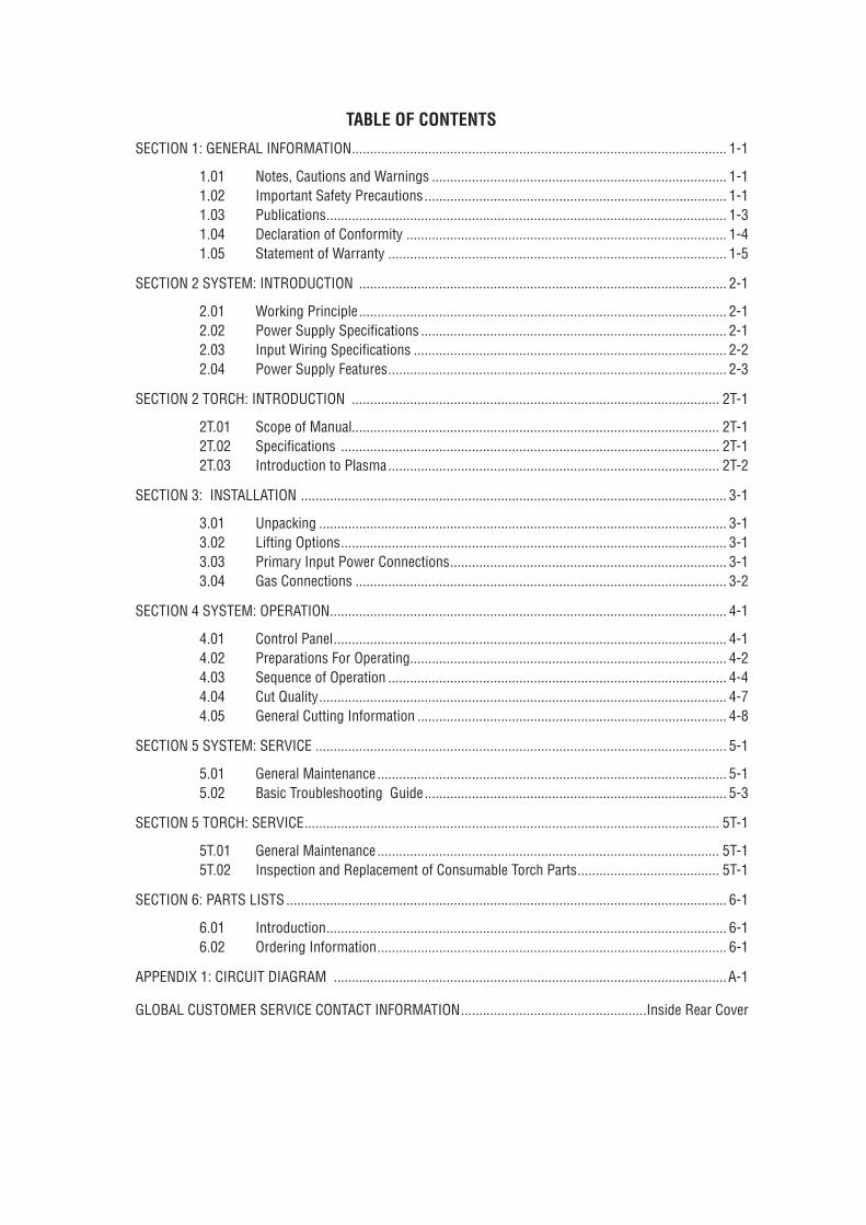
TABLE OF CONTENTS
SECTION 1: GENERAL INFORMATION ....................................................................................................... 1-1
1.01 Notes, Cautions and Warnings ................................................................................. 1-11.02 Important Safety Precautions ................................................................................... 1-11.03 Publications .............................................................................................................. 1-31.04 Declaration of Conformity ........................................................................................ 1-41.05 Statement of Warranty ............................................................................................. 1-5
SECTION 2 SYSTEM: INTRODUCTION ..................................................................................................... 2-1
2.01 Working Principle ..................................................................................................... 2-12.02 Power Supply Specifications .................................................................................... 2-12.03 Input Wiring Specifications ...................................................................................... 2-22.04 Power Supply Features ............................................................................................. 2-3
SECTION 2 TORCH: INTRODUCTION ..................................................................................................... 2T-1
2T.01 Scope of Manual..................................................................................................... 2T-12T.02 Specifications ........................................................................................................ 2T-12T.03 Introduction to Plasma ........................................................................................... 2T-2
SECTION 3: INSTALLATION ..................................................................................................................... 3-1
3.01 Unpacking ................................................................................................................ 3-13.02 Lifting Options .......................................................................................................... 3-13.03 Primary Input Power Connections ............................................................................ 3-13.04 Gas Connections ...................................................................................................... 3-2
SECTION 4 SYSTEM: OPERATION ............................................................................................................. 4-1
4.01 Control Panel ............................................................................................................ 4-14.02 Preparations For Operating....................................................................................... 4-24.03 Sequence of Operation ............................................................................................. 4-44.04 Cut Quality ................................................................................................................ 4-74.05 General Cutting Information ..................................................................................... 4-8
SECTION 5 SYSTEM: SERVICE ................................................................................................................. 5-1
5.01 General Maintenance ................................................................................................ 5-15.02 Basic Troubleshooting Guide ................................................................................... 5-3
SECTION 5 TORCH: SERVICE .................................................................................................................. 5T-1
5T.01 General Maintenance .............................................................................................. 5T-15T.02 Inspection and Replacement of Consumable Torch Parts ....................................... 5T-1
SECTION 6: PARTS LISTS ......................................................................................................................... 6-1
6.01 Introduction .............................................................................................................. 6-16.02 Ordering Information ................................................................................................ 6-1
APPENDIX 1: CIRCUIT DIAGRAM ............................................................................................................A-1
GLOBAL CUSTOMER SERVICE CONTACT INFORMATION ...................................................Inside Rear Cover
cutskill35A
June 30, 2009 1-1 GENERAL INFORMATION
SECTION 1: GENERAL INFORMATION
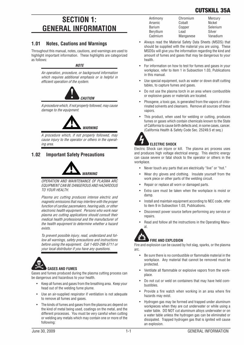
1.01 Notes, Cautions and WarningsThroughout this manual, notes, cautions, and warnings are used to highlight important information. These highlights are categorized as follows:
NOTE
An operation, procedure, or background information which requires additional emphasis or is helpful in efficient operation of the system.
CAUTION
A procedure which, if not properly followed, may cause damage to the equipment.
! WARNING
A procedure which, if not properly followed, may cause injury to the operator or others in the operat-ing area.
1.02 Important Safety Precautions
! WARNING
OPERATION AND MAINTENANCE OF PLASMA ARC EQUIPMENT CAN BE DANGEROUS AND HAZARDOUS TO YOUR HEALTH.
Plasma arc cutting produces intense electric and magnetic emissions that may interfere with the proper function of cardiac pacemakers, hearing aids, or other electronic health equipment. Persons who work near plasma arc cutting applications should consult their medical health professional and the manufacturer of the health equipment to determine whether a hazard exists.
To prevent possible injury, read, understand and fol-low all warnings, safety precautions and instructions before using the equipment. Call 1-603-298-5711 or your local distributor if you have any questions.
GASES AND FUMESGases and fumes produced during the plasma cutting process can be dangerous and hazardous to your health.
• Keep all fumes and gases from the breathing area. Keep your head out of the welding fume plume.
• Use an air-supplied respirator if ventilation is not adequate to remove all fumes and gases.
• The kinds of fumes and gases from the plasma arc depend on the kind of metal being used, coatings on the metal, and the different processes. You must be very careful when cutting or welding any metals which may contain one or more of the following:
Antimony Chromium Mercury Arsenic Cobalt Nickel Barium Copper Selenium Beryllium Lead Silver Cadmium Manganese Vanadium
• Always read the Material Safety Data Sheets (MSDS) that should be supplied with the material you are using. These MSDSs will give you the information regarding the kind and amount of fumes and gases that may be dangerous to your health.
• For information on how to test for fumes and gases in your workplace, refer to item 1 in Subsection 1.03, Publications in this manual.
• Use special equipment, such as water or down draft cutting tables, to capture fumes and gases.
• Do not use the plasma torch in an area where combustible or explosive gases or materials are located.
• Phosgene, a toxic gas, is generated from the vapors of chlo-rinated solvents and cleansers. Remove all sources of these vapors.
• This product, when used for welding or cutting, produces fumes or gases which contain chemicals known to the State of California to cause birth defects and, in some cases, cancer. (California Health & Safety Code Sec. 25249.5 et seq.)
ELECTRIC SHOCKElectric Shock can injure or kill. The plasma arc process uses and produces high voltage electrical energy. This electric energy can cause severe or fatal shock to the operator or others in the workplace.
• Never touch any parts that are electrically “live” or “hot.”
• Wear dry gloves and clothing. Insulate yourself from the work piece or other parts of the welding circuit.
• Repair or replace all worn or damaged parts.
• Extra care must be taken when the workplace is moist or damp.
• Install and maintain equipment according to NEC code, refer to item 9 in Subsection 1.03, Publications.
• Disconnect power source before performing any service or repairs.
• Read and follow all the instructions in the Operating Manu-al.
FIRE AND EXPLOSIONFire and explosion can be caused by hot slag, sparks, or the plasma arc.
• Be sure there is no combustible or flammable material in the workplace. Any material that cannot be removed must be protected.
• Ventilate all flammable or explosive vapors from the work-place.
• Do not cut or weld on containers that may have held com-bustibles.
• Provide a fire watch when working in an area where fire hazards may exist.
• Hydrogen gas may be formed and trapped under aluminum workpieces when they are cut underwater or while using a water table. DO NOT cut aluminum alloys underwater or on a water table unless the hydrogen gas can be eliminated or dissipated. Trapped hydrogen gas that is ignited will cause an explosion.
cutskill35A
GENERAL INFORMATON 1-2 June 30, 2009
NOISENoise can cause permanent hearing loss. Plasma arc processes can cause noise levels to exceed safe limits. You must protect your ears from loud noise to prevent permanent loss of hearing.
• To protect your hearing from loud noise, wear protective ear plugs and/or ear muffs. Protect others in the work-place.
• Noise levels should be measured to be sure the decibels (sound) do not exceed safe levels.
• For information on how to test for noise, see item 1 in Sub-section 1.03, Publications, in this manual.
PLASMA ARC RAYSPlasma Arc Rays can injure your eyes and burn your skin. The plasma arc process produces very bright ultra violet and infrared light. These arc rays will damage your eyes and burn your skin if you are not properly protected.
• To protect your eyes, always wear a welding helmet or shield. Also always wear safety glasses with side shields, goggles or other protective eye wear.
• Wear welding gloves and suitable clothing to protect your skin from the arc rays and sparks.
• Keep helmet and safety glasses in good condition. Replace lenses when cracked, chipped or dirty.
• Protect others in the work area from the arc rays. Use protec-tive booths, screens or shields.
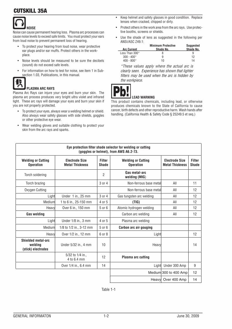
• Use the shade of lens as suggested in the following per ANSI/ASC Z49.1:
Minimum Protective Suggested Arc Current Shade No. Shade No. Less Than 300* 8 9 300 - 400* 9 12 400 - 800* 10 14
*These values apply where the actual arc is clearly seen. Experience has shown that lighter filters may be used when the arc is hidden by the workpiece.
LEAD WARNINGThis product contains chemicals, including lead, or otherwise produces chemicals known to the State of California to cause cancer, birth defects and other reproductive harm. Wash hands after handling. (California Health & Safety Code § 25249.5 et seq.)
Eye protection fi lter shade selector for welding or cutting(goggles or helmet), from AWS A6.2-73.
Welding or Cutting Operation
Electrode SizeMetal Thickness
FilterShade
Welding or Cutting Operation
Electrode SizeMetal Thickness
FilterShade
Torch soldering 2 Gas metal-arc welding (MIG)
Torch brazing 3 or 4 Non-ferrous base metal All 11
Oxygen Cutting Non-ferrous base metal All 12
Light Under 1 in., 25 mm 3 or 4 Gas tungsten arc welding All 12
Medium 1 to 6 in., 25-150 mm 4 or 5 (TIG) All 12
Heavy Over 6 in., 150 mm 5 or 6 Atomic hydrogen welding All 12
Gas welding Carbon arc welding All 12
Light Under 1/8 in., 3 mm 4 or 5 Plasma arc welding
Medium 1/8 to 1/2 in., 3-12 mm 5 or 6 Carbon arc air gouging
Heavy Over 1/2 in., 12 mm 6 or 8 Light 12
Shielded metal-arc welding
(stick) electrodesUnder 5/32 in., 4 mm 10 Heavy 14
5/32 to 1/4 in., 4 to 6.4 mm 12 Plasma arc cutting
Over 1/4 in., 6.4 mm 14 Light Under 300 Amp 9
Medium 300 to 400 Amp 12
Heavy Over 400 Amp 14
Table 1-1
cutskill35A
June 30, 2009 1-3 GENERAL INFORMATION
1.03 PublicationsRefer to the following standards or their latest revisions for more information:
1. OSHA, SAFETY AND HEALTH STANDARDS, 29CFR 1910, obtainable from the Superintendent of Documents, U.S. Government Printing Office, Washington, D.C. 20402
2. ANSI Standard Z49.1, SAFETY IN WELDING AND CUTTING, obtainable from the American Welding Society, 550 N.W. LeJeune Rd, Miami, FL 33126
3. NIOSH, SAFETY AND HEALTH IN ARC WELDING AND GAS WELDING AND CUTTING, obtainable from the Superin-tendent of Documents, U.S. Government Printing Office, Washington, D.C. 20402
4. ANSI Standard Z87.1, SAFE PRACTICES FOR OCCUPATION AND EDUCATIONAL EYE AND FACE PROTECTION, obtain-able from American National Standards Institute, 1430 Broadway, New York, NY 10018
5. ANSI Standard Z41.1, STANDARD FOR MEN’S SAFETY-TOE FOOTWEAR, obtainable from the American National Stan-dards Institute, 1430 Broadway, New York, NY 10018
6. ANSI Standard Z49.2, FIRE PREVENTION IN THE USE OF CUTTING AND WELDING PROCESSES, obtainable from American National Standards Institute, 1430 Broadway, New York, NY 10018
7. AWS Standard A6.0, WELDING AND CUTTING CONTAIN-ERS WHICH HAVE HELD COMBUSTIBLES, obtainable from American Welding Society, 550 N.W. LeJeune Rd, Miami, FL 33126
8. NFPA Standard 51, OXYGEN-FUEL GAS SYSTEMS FOR WELDING, CUTTING AND ALLIED PROCESSES, obtainable from the National Fire Protection Association, Batterymarch Park, Quincy, MA 02269
9. NFPA Standard 70, NATIONAL ELECTRICAL CODE, obtain-able from the National Fire Protection Association, Bat-terymarch Park, Quincy, MA 02269
10. NFPA Standard 51B, CUTTING AND WELDING PROCESSES, obtainable from the National Fire Protection Association, Batterymarch Park, Quincy, MA 02269
11. CGA Pamphlet P-1, SAFE HANDLING OF COMPRESSED GASES IN CYLINDERS, obtainable from the Compressed Gas Association, 1235 Jefferson Davis Highway, Suite 501, Arlington, VA 22202
12. CSA Standard W117.2, CODE FOR SAFETY IN WELDING AND CUTTING, obtainable from the Canadian Standards Association, Standards Sales, 178 Rexdale Boulevard, Rexdale, Ontario, Canada M9W 1R3
13. NWSA booklet, WELDING SAFETY BIBLIOGRAPHY obtain-able from the National Welding Supply Association, 1900 Arch Street, Philadelphia, PA 19103
14. American Welding Society Standard AWSF4.1, RECOM-MENDED SAFE PRACTICES FOR THE PREPARATION FOR WELDING AND CUTTING OF CONTAINERS AND PIPING THAT HAVE HELD HAZARDOUS SUBSTANCES, obtainable from the American Welding Society, 550 N.W. LeJeune Rd, Miami, FL 33126
15. ANSI Standard Z88.2, PRACTICE FOR RESPIRATORY PRO-TECTION, obtainable from American National Standards Institute, 1430 Broadway, New York, NY 10018
16. Safety in Welding and Allied Processes Part 2: Electrical, AS1674.2-2007 from SAI Global Limited, www.saiglobal.com
cutskill35A
GENERAL INFORMATON 1-4 June 30, 2009
1.04 Declaration of Conformity
Manufacturer: Thermadyne CompanyAddress: 82 Benning Street West Lebanon, New Hampshire 03784 USA
The equipment described in this manual conforms to all applicable aspects and regulations of the ‘Low Voltage Directive’ (European Council Directive 73/23/EEC as amended by Council Directive 93/68/EEC) and to the National legislation for the enforcement of this Directive.
The equipment described in this manual conforms to all applicable aspects and regulations of the "EMC Directive" (European Council Directive 89/336/EEC) and to the National legislation for the enforcement of this Directive.
Serial numbers are unique with each individual piece of equipment and details description, parts used to manufacture a unit and date of manufacture.
National Standard and Technical Specifications
The product is designed and manufactured to a number of standards and technical requirements. Among them are:
* CSA (Canadian Standards Association) standard C22.2 number 60 for Arc welding equipment.
* UL (Underwriters Laboratory) rating 94VO flammability testing for all printed-circuit boards used.
* CENELEC EN50199 EMC Product Standard for Arc Welding Equipment.
* ISO/IEC 60974-1 (BS 638-PT10) (EN 60 974-1) (EN50192) (EN50078) applicable to plasma cutting equipment and associated accessories.
* AS60974.1 Arc Welding Equipment Welding Power Sources.
For environments with increased hazard of electrical shock, Power Supplies bearing the mark conform to EN50192 when used in conjunction with hand torches with exposed cutting tips, if equipped with properly installed standoff guides.
* Extensive product design verification is conducted at the manufacturing facility as part of the routine design and manufacturing process. This is to ensure the product is safe, when used according to instructions in this manual and related industry standards, and performs as specified. Rigorous testing is incorporated into the manufacturing process to ensure the manufactured product meets or exceeds all design specifications.
Thermadyne has been manufacturing products for more than 30 years, and will continue to achieve excellence in our area of manufacture.
Manufacturers responsible representative in Europe: Steve Ward Operations Director Thermadyne Europe Europa Building Chorley N Industrial Park Chorley, Lancashire, England PR6 7BX
cutskill35A
June 30, 2009 1-5 GENERAL INFORMATION
1.05 Statement of Warranty
LIMITED WARRANTY: Subject to the terms and conditions established below, Thermadyne Company warrants to the original retail purchaser that new Thermal Dynamics CUTSKILL™ plasma cutting systems sold after the effective date of this warranty are free of defects in material and workmanship. Should any failure to conform to this warranty appear within the applicable period stated below, Thermadyne Company shall, upon notification thereof and substantiation that the product has been stored operated and maintained in accordance with Thermadyne’s specifications, instructions, recommendations and recognized industry practice, correct such defects by suitable repair or replacement.
This warranty is exclusive and in lieu of any warranty of merchantability or fitness for a particular purpose.
Thermadyne will repair or replace, at its discretion, any warranted parts or components that fail due to defects in material or workmanship within the time periods set out below. Thermadyne Company must be notified within 30 days of any failure, at which time Thermadyne Company will provide instructions on the warranty procedures to be implemented.
Thermadyne Company will honor warranty claims submitted within the warranty periods listed below. All warranty periods begin on the date of sale of the product to the original retail customer or 1 year after sale to an authorized Thermadyne Distributor.
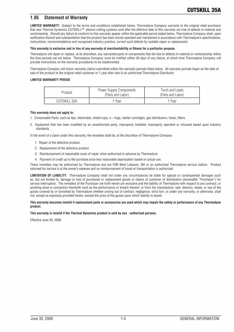
LIMITED WARRANTY PERIOD
ProductPower Supply Components
(Parts and Labor)Torch and Leads(Parts and Labor)
CUTSKILL 35A 1 Year 1 Year
This warranty does not apply to:
1. Consumable Parts, such as tips, electrodes, shield cups, o - rings, starter cartridges, gas distributors, fuses, filters.
2. Equipment that has been modified by an unauthorized party, improperly installed, improperly operated or misused based upon industry standards.
In the event of a claim under this warranty, the remedies shall be, at the discretion of Thermadyne Company:
1. Repair of the defective product.
2. Replacement of the defective product.
3. Reimbursement of reasonable costs of repair when authorized in advance by Thermadyne.
4. Payment of credit up to the purchase price less reasonable depreciation based on actual use.
These remedies may be authorized by Thermadyne and are FOB West Lebanon, NH or an authorized Thermadyne service station. Product returned for service is at the owner’s expense and no reimbursement of travel or transportation is authorized.
LIMITATION OF LIABILITY: Thermadyne Company shall not under any circumstances be liable for special or consequential damages such as, but not limited to, damage or loss of purchased or replacement goods or claims of customer of distributors (hereinafter “Purchaser”) for service interruption. The remedies of the Purchaser set forth herein are exclusive and the liability of Thermadyne with respect to any contract, or anything done in connection therewith such as the performance or breach thereof, or from the manufacture, sale, delivery, resale, or use of the goods covered by or furnished by Thermadyne whether arising out of contract, negligence, strict tort, or under any warranty, or otherwise, shall not, except as expressly provided herein, exceed the price of the goods upon which liability is based.
This warranty becomes invalid if replacement parts or accessories are used which may impair the safety or performance of any Thermadyne product.
This warranty is invalid if the Thermal Dynamics product is sold by non - authorized persons.
Effective June 30, 2009

cutskill 35a
June 30, 2009 2-1 INTRODUCTION
SECTION 2 SYSTEM: INTRODUCTION
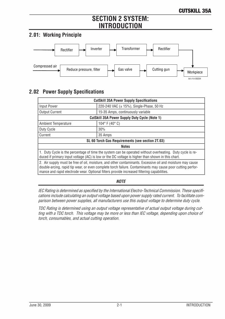
2.01: Working Principle
Rectifier Inverter Transformer Rectifier
Reduce pressure, filter Gas valve Cutting gun Workpiece
Compressed air
Art # A-09204
2.02 Power Supply SpecificationsCutSkill 35A Power Supply Specifications
Input Power 220-240 VAC (± 15%), Single-Phase, 50 HzOutput Current 15-35 Amps, continuously variable
CutSkill 35A Power Supply Duty Cycle (Note 1)Ambient Temperature 104° F (40° C)Duty Cycle 30%Current 35 Amps
SL 60 Torch Gas Requirements (see section 2T.03)Notes
1. Duty Cycle is the percentage of time the system can be operated without overheating. Duty cycle is re-duced if primary input voltage (AC) is low or the DC voltage is higher than shown in this chart.2. Air supply must be free of oil, moisture, and other contaminants. Excessive oil and moisture may cause double-arcing, rapid tip wear, or even complete torch failure. Contaminants may cause poor cutting perfor-mance and rapid electrode wear. Optional filters provide increased filtering capabilities.
NOTE
IEC Rating is determined as specified by the International Electro-Technical Commission. These specifi-cations include calculating an output voltage based upon power supply rated current. To facilitate com-parison between power supplies, all manufacturers use this output voltage to determine duty cycle.
TDC Rating is determined using an output voltage representative of actual output voltage during cut-ting with a TDC torch. This voltage may be more or less than IEC voltage, depending upon choice of torch, consumables, and actual cutting operation.
cutskill 35a
INTRODUCTION 2-2 June 30, 2009
26lb / 11.8kg5 1/4"
133 mm
16 1/2"419 mm
RUN
SET
CURRENT (A)
25
35
READYAIR
OVERHEATPOWER
11"280 mm
Art # A-09174
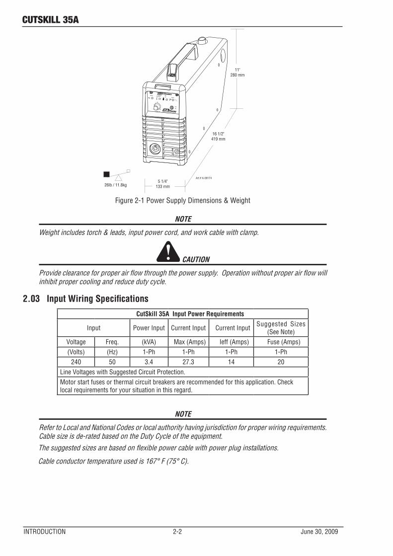
Figure 2-1 Power Supply Dimensions & Weight
NOTE
Weight includes torch & leads, input power cord, and work cable with clamp.
CAUTION
Provide clearance for proper air flow through the power supply. Operation without proper air flow will inhibit proper cooling and reduce duty cycle.
2.03 Input Wiring SpecificationsCutSkill 35A Input Power Requirements
Input Power Input Current Input Current Input Suggested Sizes (See Note)
Voltage Freq. (kVA) Max (Amps) Ieff (Amps) Fuse (Amps)(Volts) (Hz) 1-Ph 1-Ph 1-Ph 1-Ph
240 50 3.4 27.3 14 20Line Voltages with Suggested Circuit Protection. Motor start fuses or thermal circuit breakers are recommended for this application. Check local requirements for your situation in this regard.
NOTE
Refer to Local and National Codes or local authority having jurisdiction for proper wiring requirements. Cable size is de-rated based on the Duty Cycle of the equipment.The suggested sizes are based on flexible power cable with power plug installations.
Cable conductor temperature used is 167° F (75° C).
cutskill 35a
June 30, 2009 2-3 INTRODUCTION
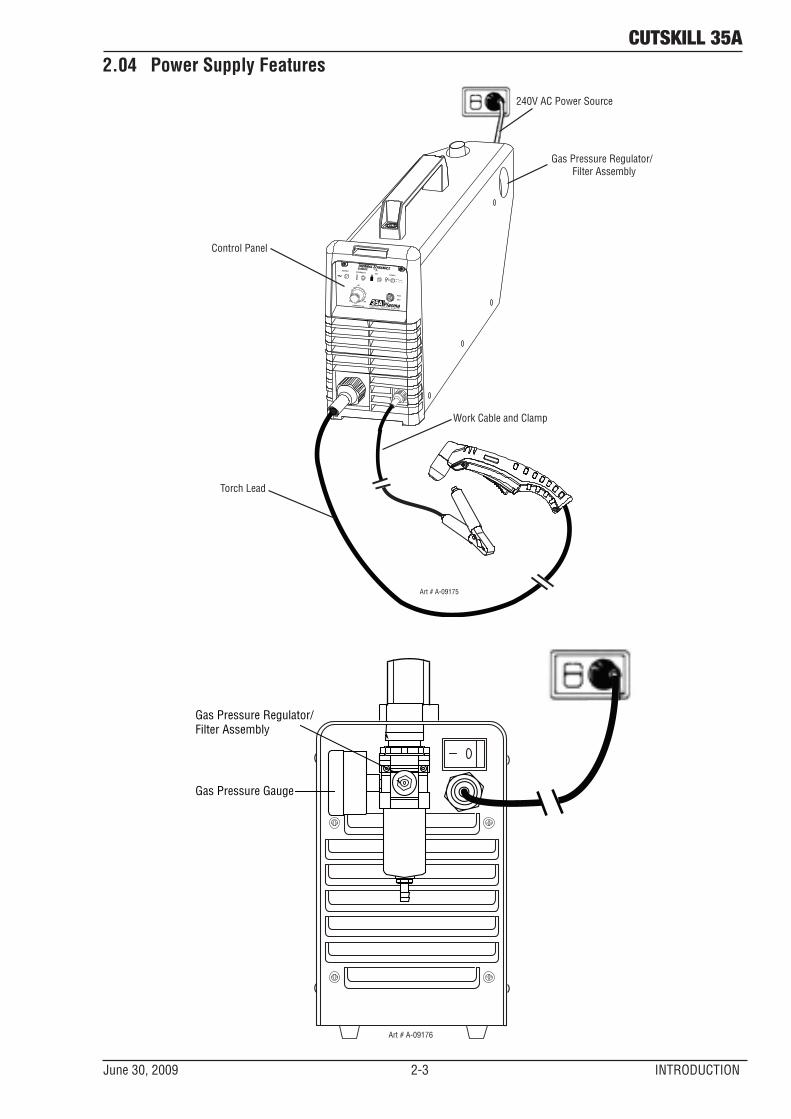
2.04 Power Supply Features
Gas Pressure Regulator/ Filter Assembly
Control Panel
Torch Lead
RUN
SET
CURRENT (A)
25
35
READYAIR
OVERHEATPOWER
240V AC Power Source
Work Cable and Clamp
Art # A-09175
Gas Pressure Regulator/Filter Assembly
Gas Pressure Gauge
Art # A-09176

This Page left blank intentionally.
cutSKILL 35a
June 30, 2009 2T-1 INTRODUCTION
SECTION 2 TORCH: INTRODUCTION
2T.01 Scope of ManualThis manual contains descriptions, operating instruc-tions and maintenance procedures for the 1Torch Model SL60 Plasma Cutting Torch. Service of this equipment is restricted to properly trained personnel; unqualified per-sonnel are strictly cautioned against attempting repairs or adjustments not covered in this manual, at the risk of voiding the Warranty. Read this manual thoroughly. A complete understanding of the characteristics and capabilities of this equipment will assure the dependable operation for which it was designed.
2T.02 Specifications
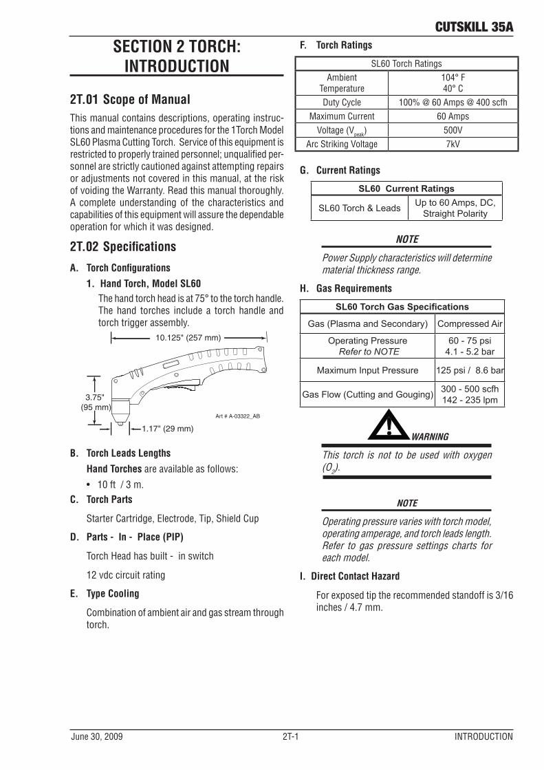
A. Torch Configurations
1. Hand Torch, Model SL60The hand torch head is at 75° to the torch handle. The hand torches include a torch handle and torch trigger assembly.
10.125" (257 mm)
3.75" (95 mm)
1.17" (29 mm)
Art # A-03322_AB
B. Torch Leads Lengths
Hand Torches are available as follows:
• 10 ft / 3 m.C. Torch Parts
Starter Cartridge, Electrode, Tip, Shield Cup
D. Parts - In - Place (PIP)
Torch Head has built - in switch
12 vdc circuit rating
E. Type Cooling
Combination of ambient air and gas stream through torch.
F. Torch Ratings
SL60 Torch RatingsAmbient
Temperature104° F 40° C
Duty Cycle 100% @ 60 Amps @ 400 scfhMaximum Current 60 Amps
Voltage (Vpeak) 500VArc Striking Voltage 7kV
G. Current Ratings
SL60 Current Ratings
SL60 Torch & Leads Up to 60 Amps, DC, Straight Polarity
NOTE
Power Supply characteristics will determine material thickness range.
H. Gas Requirements
SL60 Torch Gas Specifications
Gas (Plasma and Secondary) Compressed Air
Operating Pressure Refer to NOTE
60 - 75 psi 4.1 - 5.2 bar
Maximum Input Pressure 125 psi / 8.6 bar
Gas Flow (Cutting and Gouging) 300 - 500 scfh 142 - 235 lpm
! WARNING
This torch is not to be used with oxygen (O2).
NOTE
Operating pressure varies with torch model, operating amperage, and torch leads length. Refer to gas pressure settings charts for each model.
I. Direct Contact Hazard
For exposed tip the recommended standoff is 3/16 inches / 4.7 mm.
CUTSkILL 35A
INTRODUCTION 2T-2 June 30, 2009
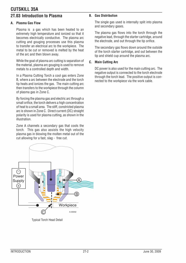
2T.03 Introduction to Plasma
A. Plasma Gas Flow
Plasma is a gas which has been heated to an extremely high temperature and ionized so that it becomes electrically conductive. The plasma arc cutting and gouging processes use this plasma to transfer an electrical arc to the workpiece. The metal to be cut or removed is melted by the heat of the arc and then blown away.
While the goal of plasma arc cutting is separation of the material, plasma arc gouging is used to remove metals to a controlled depth and width.
In a Plasma Cutting Torch a cool gas enters Zone B, where a arc between the electrode and the torch tip heats and ionizes the gas. The main cutting arc then transfers to the workpiece through the column of plasma gas in Zone C.
By forcing the plasma gas and electric arc through a small orifice, the torch delivers a high concentration of heat to a small area. The stiff, constricted plasma arc is shown in Zone C. Direct current (DC) straight polarity is used for plasma cutting, as shown in the illustration.
Zone A channels a secondary gas that cools the torch. This gas also assists the high velocity plasma gas in blowing the molten metal out of the cut allowing for a fast, slag - free cut.
A-00002
Workpiece
PowerSupply
+
_
C
B
A
Typical Torch Head Detail
B. Gas Distribution
The single gas used is internally split into plasma and secondary gases.
The plasma gas flows into the torch through the negative lead, through the starter cartridge, around the electrode, and out through the tip orifice.
The secondary gas flows down around the outside of the torch starter cartridge, and out between the tip and shield cup around the plasma arc.
C. Main Cutting Arc
DC power is also used for the main cutting arc. The negative output is connected to the torch electrode through the torch lead. The positive output is con-nected to the workpiece via the work cable.
cutskill 35a
June 30, 2009 3-1 INSTALLATION
SECTION 3: INSTALLATION
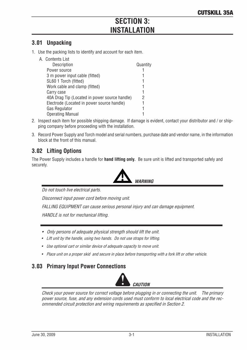
3.01 Unpacking1. Use the packing lists to identify and account for each item.
A. Contents List Description Quantity Power source 1 3 m power input cable (fitted) 1 SL60 1 Torch (fitted) 1 Work cable and clamp (fitted) 1 Carry case 1 40A Drag Tip (Located in power source handle) 2 Electrode (Located in power source handle) 1 Gas Regulator 1 Operating Manual 1
2. Inspect each item for possible shipping damage. If damage is evident, contact your distributor and / or ship-ping company before proceeding with the installation.
3. Record Power Supply and Torch model and serial numbers, purchase date and vendor name, in the information block at the front of this manual.
3.02 Lifting OptionsThe Power Supply includes a handle for hand lifting only. Be sure unit is lifted and transported safely and securely.
! WARNING
Do not touch live electrical parts.
Disconnect input power cord before moving unit.
FALLING EQUIPMENT can cause serious personal injury and can damage equipment.
HANDLE is not for mechanical lifting.
• Only persons of adequate physical strength should lift the unit.• Lift unit by the handle, using two hands. Do not use straps for lifting.
• Use optional cart or similar device of adequate capacity to move unit.
• Place unit on a proper skid and secure in place before transporting with a fork lift or other vehicle.
3.03 Primary Input Power Connections
CAUTION
Check your power source for correct voltage before plugging in or connecting the unit. The primary power source, fuse, and any extension cords used must conform to local electrical code and the rec-ommended circuit protection and wiring requirements as specified in Section 2.
cutskill 35a
INSTALLATION 3-2 June 30, 2009
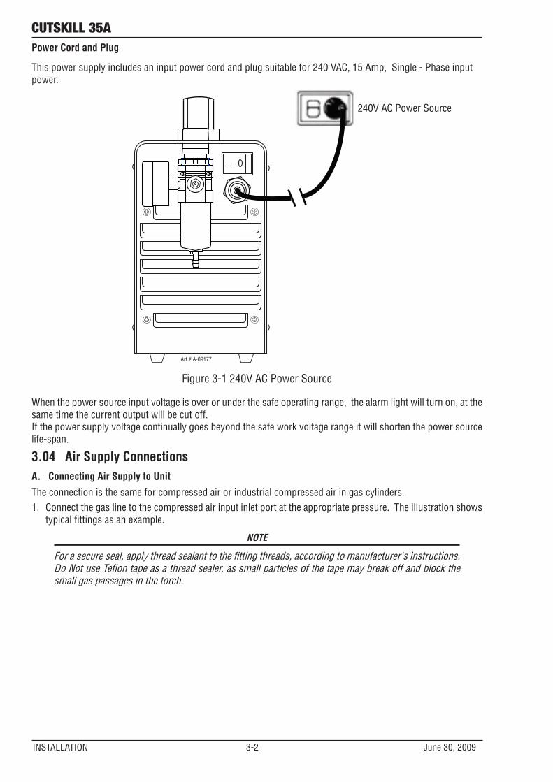
Power Cord and Plug
This power supply includes an input power cord and plug suitable for 240 VAC, 15 Amp, Single - Phase input power.
Art # A-09177
240V AC Power Source
Figure 3-1 240V AC Power Source
When the power source input voltage is over or under the safe operating range, the alarm light will turn on, at the same time the current output will be cut off. If the power supply voltage continually goes beyond the safe work voltage range it will shorten the power source life-span.
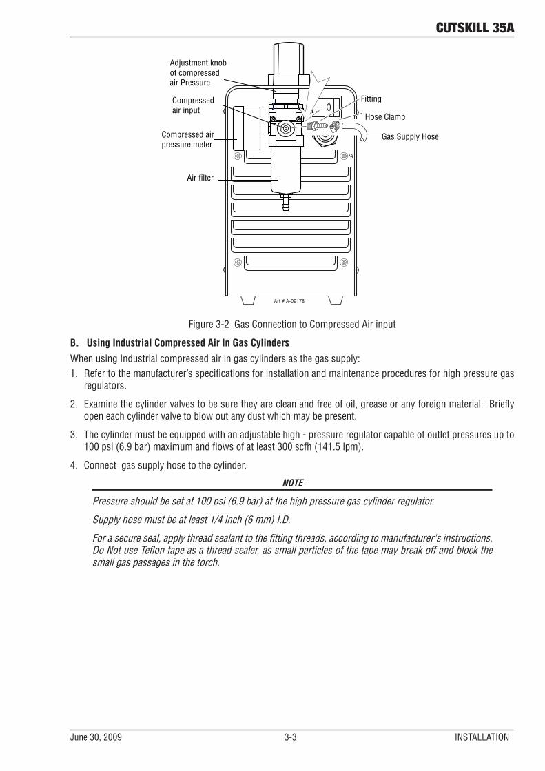
3.04 Air Supply ConnectionsA. Connecting Air Supply to Unit
The connection is the same for compressed air or industrial compressed air in gas cylinders. 1. Connect the gas line to the compressed air input inlet port at the appropriate pressure. The illustration shows
typical fittings as an example.
NOTE
For a secure seal, apply thread sealant to the fitting threads, according to manufacturer's instructions. Do Not use Teflon tape as a thread sealer, as small particles of the tape may break off and block the small gas passages in the torch.
cutskill 35a
June 30, 2009 3-3 INSTALLATION
Gas Supply Hose
Adjustment knob of compressed air Pressure
Compressed airpressure meter
Air filter
Compressed air input
Art # A-09178
Hose Clamp
Fitting
Figure 3-2 Gas Connection to Compressed Air input
B. Using Industrial Compressed Air In Gas Cylinders
When using Industrial compressed air in gas cylinders as the gas supply:1. Refer to the manufacturer’s specifications for installation and maintenance procedures for high pressure gas
regulators.
2. Examine the cylinder valves to be sure they are clean and free of oil, grease or any foreign material. Briefly open each cylinder valve to blow out any dust which may be present.
3. The cylinder must be equipped with an adjustable high - pressure regulator capable of outlet pressures up to 100 psi (6.9 bar) maximum and flows of at least 300 scfh (141.5 lpm).
4. Connect gas supply hose to the cylinder.
NOTE
Pressure should be set at 100 psi (6.9 bar) at the high pressure gas cylinder regulator.
Supply hose must be at least 1/4 inch (6 mm) I.D.
For a secure seal, apply thread sealant to the fitting threads, according to manufacturer's instructions. Do Not use Teflon tape as a thread sealer, as small particles of the tape may break off and block the small gas passages in the torch.

This page left blank intentionally.
cutSKILL 35A
June 30, 2009 4-1 OPERATION
SECTION 4 SYSTEM: OPERATION
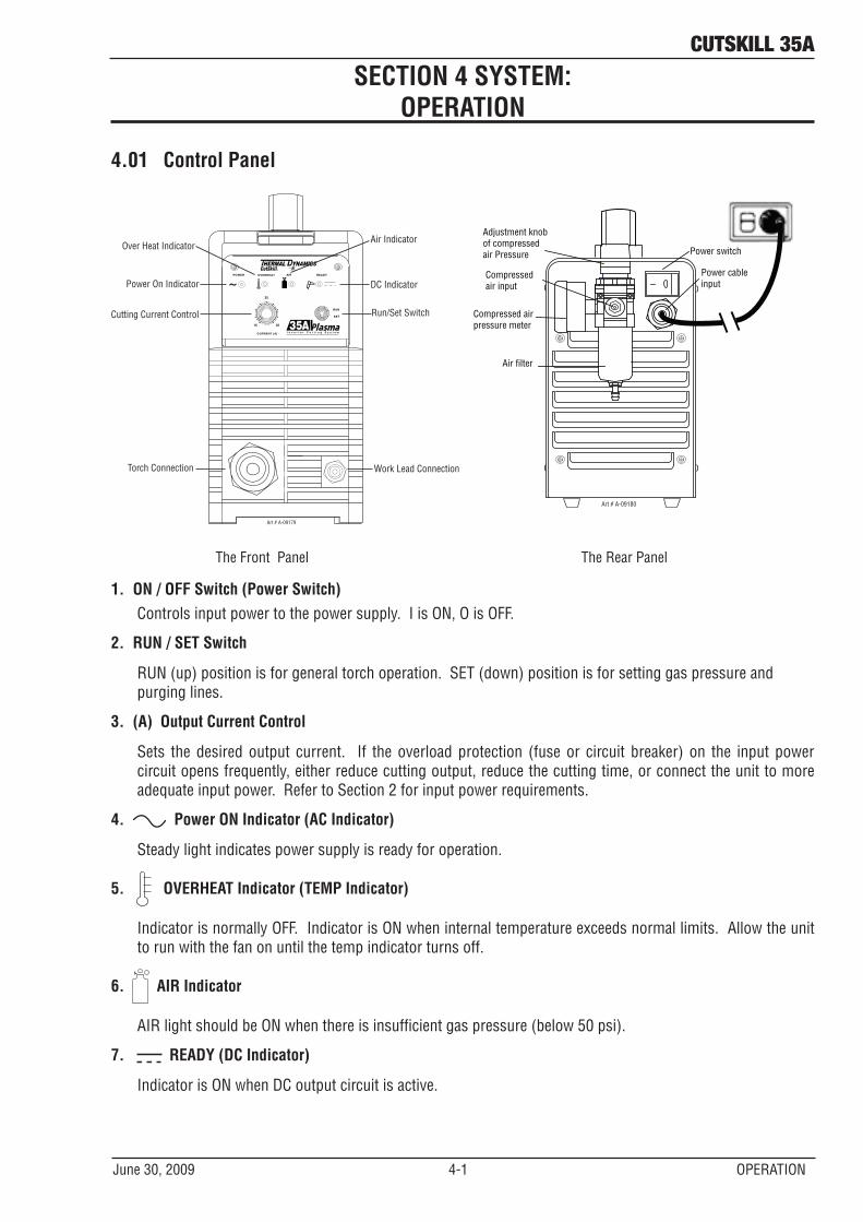
4.01 Control Panel
RUN
SET
CURRENT (A)
15
25
35
READYAIROVERHEATPOWER
Cutting Current Control
Work Lead Connection
Power On Indicator
Torch Connection
Run/Set Switch
Over Heat IndicatorAir Indicator
DC Indicator
Art # A-09179
Adjustment knob of compressed air Pressure Power switch
Compressed airpressure meter
Power cable input
Air filter
Compressed air input
Art # A-09180
The Front Panel The Rear Panel
1. ON / OFF Switch (Power Switch)Controls input power to the power supply. I is ON, O is OFF.
2. RUN / SET Switch
RUN (up) position is for general torch operation. SET (down) position is for setting gas pressure and purging lines.
3. (A) Output Current Control
Sets the desired output current. If the overload protection (fuse or circuit breaker) on the input power circuit opens frequently, either reduce cutting output, reduce the cutting time, or connect the unit to more adequate input power. Refer to Section 2 for input power requirements.
4. Power ON Indicator (AC Indicator)
Steady light indicates power supply is ready for operation.
5. OVERHEAT Indicator (TEMP Indicator)
Indicator is normally OFF. Indicator is ON when internal temperature exceeds normal limits. Allow the unit to run with the fan on until the temp indicator turns off.
6. AIR Indicator
AIR light should be ON when there is insufficient gas pressure (below 50 psi).
7. READY (DC Indicator)
Indicator is ON when DC output circuit is active.
cutSKILL 35A
OPERATION 4-2 June 30, 2009
8. Parts - in - place ( PIP)
This unit is fitted with a protective interlock mode (parts in place sensor), which serves to protect the user from potentially dangerous voltages when changing consumables. If the shield cup is not correctly fitted, the output will be disabled and the air indicator will flash.
NOTE
All consumables must be correctly fitted and maintained to ensure correct operation.
4.02 Preparations For OperatingAt the start of each operating session:
! WARNING
Disconnect primary power at the source before assembling or disassembling power supply, torch parts, or torch and leads assemblies.
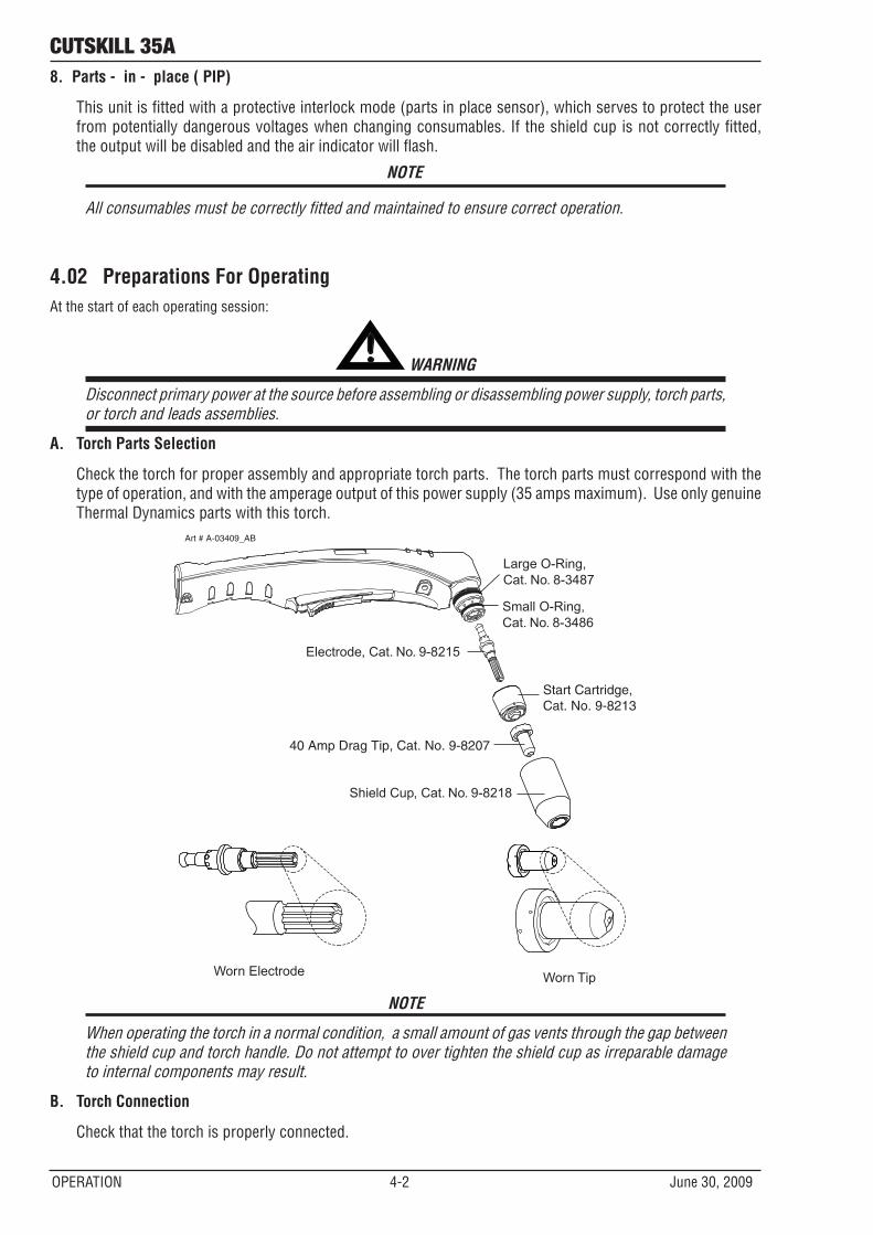
A. Torch Parts Selection
Check the torch for proper assembly and appropriate torch parts. The torch parts must correspond with the type of operation, and with the amperage output of this power supply (35 amps maximum). Use only genuine Thermal Dynamics parts with this torch.
Art # A-03409_AB
Large O-Ring, Cat. No. 8-3487
Small O-Ring,Cat. No. 8-3486
Electrode, Cat. No. 9-8215
Start Cartridge, Cat. No. 9-8213
30Amp Cutting Tip, Cat. No. 9-8206
Shield Cup, Cat. No. 9-8218
Worn Electrode Worn Tip
40 Amp Drag Tip, Cat. No. 9-8207
NOTE
When operating the torch in a normal condition, a small amount of gas vents through the gap between the shield cup and torch handle. Do not attempt to over tighten the shield cup as irreparable damage to internal components may result.
B. Torch Connection
Check that the torch is properly connected.
cutSKILL 35A
June 30, 2009 4-3 OPERATION
C. Check Primary Input Power Source
1. Check the power source for proper input voltage. Make sure the input power source meets the power requirements for the unit per Section 2, Specifications.
2. Connect the input power cable (or close the main disconnect switch) to supply power to the system.D. Gas Selection
Ensure gas source meets requirements listed in section 2T. Check connections and turn gas supply on.
E. Connect Work Cable
Clamp the work cable to the workpiece or cutting table. The area must be free from oil, paint and rust. Con-nect only to the main part of the workpiece; do not connect to the part to be cut off.
Art # A-03387
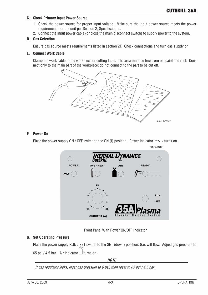
F. Power On
Place the power supply ON / OFF switch to the ON (I) position. Power indicator turns on.Art # A-09181
RUN
SET
CURRENT (A)
15
25
35
READY AIR OVERHEAT POWER
Front Panel With Power ON/OFF Indicator
G. Set Operating Pressure
Place the power supply RUN / SET switch to the SET (down) position. Gas will flow. Adjust gas pressure to
65 psi / 4.5 bar. Air indicator turns on.
NOTE
If gas regulator leaks, reset gas pressure to 0 psi, then reset to 65 psi / 4.5 bar.
cutSKILL 35A
OPERATION 4-4 June 30, 2009
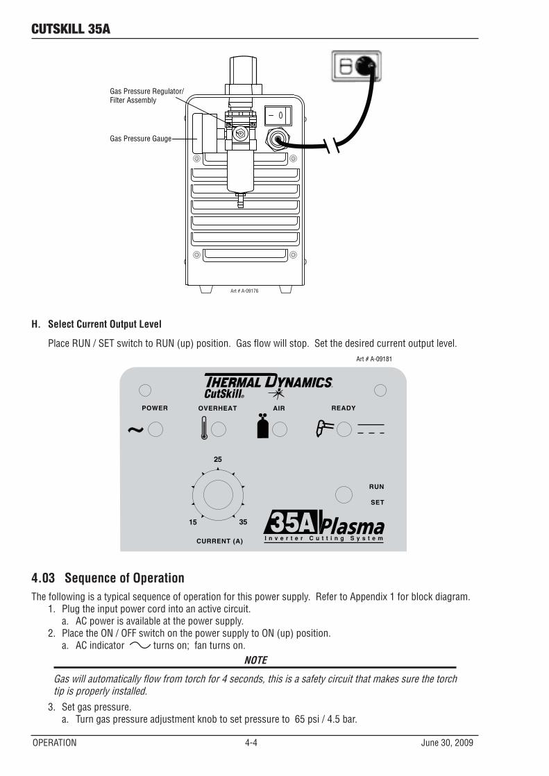
Gas Pressure Regulator/Filter Assembly
Gas Pressure Gauge
Art # A-09176
H. Select Current Output Level
Place RUN / SET switch to RUN (up) position. Gas flow will stop. Set the desired current output level.Art # A-09181
RUN
SET
CURRENT (A)
15
25
35
READY AIR OVERHEAT POWER
4.03 Sequence of OperationThe following is a typical sequence of operation for this power supply. Refer to Appendix 1 for block diagram.
1. Plug the input power cord into an active circuit. a. AC power is available at the power supply.
2. Place the ON / OFF switch on the power supply to ON (up) position.a. AC indicator turns on; fan turns on.
NOTE
Gas will automatically flow from torch for 4 seconds, this is a safety circuit that makes sure the torch tip is properly installed.
3. Set gas pressure.a. Turn gas pressure adjustment knob to set pressure to 65 psi / 4.5 bar.
cutSKILL 35A
June 30, 2009 4-5 OPERATION
NOTE
Minimum pressure for power supply op-eration is lower than minimum pressure for torch operation.
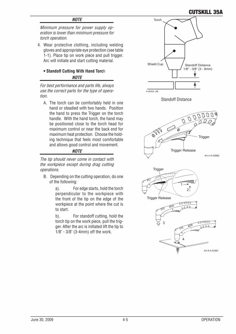
4. Wear protective clothing, including welding gloves and appropriate eye protection (see table 1-1). Place tip on work piece and pull trigger. Arc will initiate and start cutting material.
• Standoff Cutting With Hand Torch
NOTE
For best performance and parts life, always use the correct parts for the type of opera-tion.
A. The torch can be comfortably held in one hand or steadied with two hands. Position the hand to press the Trigger on the torch handle. With the hand torch, the hand may be positioned close to the torch head for maximum control or near the back end for maximum heat protection. Choose the hold-ing technique that feels most comfortable and allows good control and movement.
NOTE
The tip should never come in contact with the workpiece except during drag cutting operations.
B. Depending on the cutting operation, do one of the following: a). For edge starts, hold the torch
perpendicular to the workpiece with the front of the tip on the edge of the workpiece at the point where the cut is to start.
b). For standoff cutting, hold the torch tip on the work piece, pull the trig-ger. After the arc is initiated lift the tip to 1/8" - 3/8" (3-4mm) off the work.
A-00024_AB
Shield Cup
Torch
Standoff Distance1/8" - 3/8" (3 - 9mm)
Standoff Distance
Art # A-03962
Trigger
Trigger Release
3
4
Art # A-03383
Trigger
21
Trigger Release
cutSKILL 35A
OPERATION 4-6 June 30, 2009
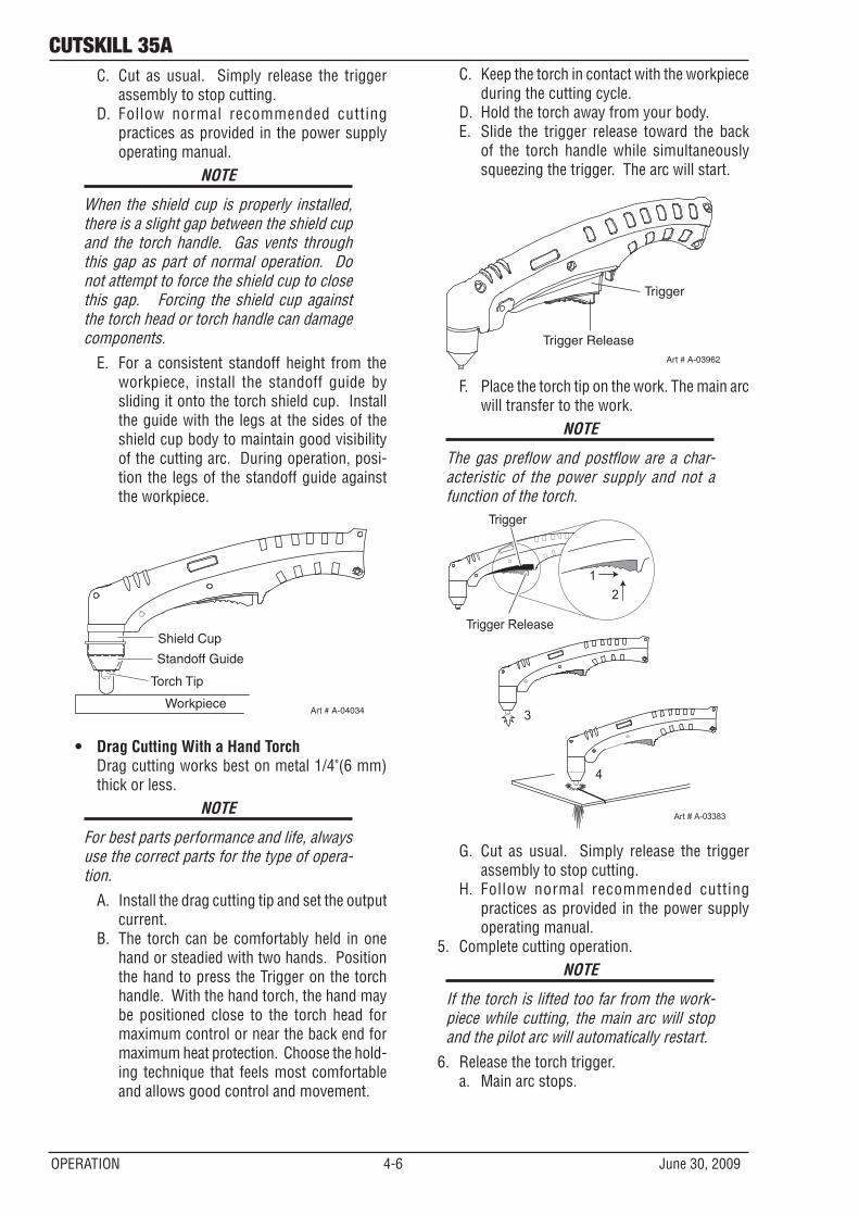
C. Cut as usual. Simply release the trigger assembly to stop cutting.
D. Follow normal recommended cutting practices as provided in the power supply operating manual.
NOTE
When the shield cup is properly installed, there is a slight gap between the shield cup and the torch handle. Gas vents through this gap as part of normal operation. Do not attempt to force the shield cup to close this gap. Forcing the shield cup against the torch head or torch handle can damage components.
E. For a consistent standoff height from the workpiece, install the standoff guide by sliding it onto the torch shield cup. Install the guide with the legs at the sides of the shield cup body to maintain good visibility of the cutting arc. During operation, posi-tion the legs of the standoff guide against the workpiece.
Shield Cup
Workpiece
Standoff Guide
Art # A-04034
Torch Tip
• Drag Cutting With a Hand Torch Drag cutting works best on metal 1/4"(6 mm)
thick or less.NOTE
For best parts performance and life, always use the correct parts for the type of opera-tion.
A. Install the drag cutting tip and set the output current.
B. The torch can be comfortably held in one hand or steadied with two hands. Position the hand to press the Trigger on the torch handle. With the hand torch, the hand may be positioned close to the torch head for maximum control or near the back end for maximum heat protection. Choose the hold-ing technique that feels most comfortable and allows good control and movement.
C. Keep the torch in contact with the workpiece during the cutting cycle.
D. Hold the torch away from your body.E. Slide the trigger release toward the back
of the torch handle while simultaneously squeezing the trigger. The arc will start.
Art # A-03962
Trigger
Trigger Release
F. Place the torch tip on the work. The main arc will transfer to the work.
NOTE
The gas preflow and postflow are a char-acteristic of the power supply and not a function of the torch.
3
4
Art # A-03383
Trigger
21
Trigger Release
G. Cut as usual. Simply release the trigger assembly to stop cutting.
H. Follow normal recommended cutting practices as provided in the power supply operating manual.
5. Complete cutting operation.NOTE
If the torch is lifted too far from the work-piece while cutting, the main arc will stop and the pilot arc will automatically restart.
6. Release the torch trigger. a. Main arc stops.
cutSKILL 35A
June 30, 2009 4-7 OPERATION
7. Set the power supply ON / OFF switch to OFF (down position).a. AC indicator turns OFF.
8. Set the main power disconnect to OFF, or unplug input power cord.a. Input power is removed from the system.
4.04 Cut Quality
NOTE
Cut quality depends heavily on setup and parameters such as torch standoff, align-ment with the workpiece, cutting speed, gas pressures, and operator ability.
Refer to appendix pages for additional information as related to the power supply used.
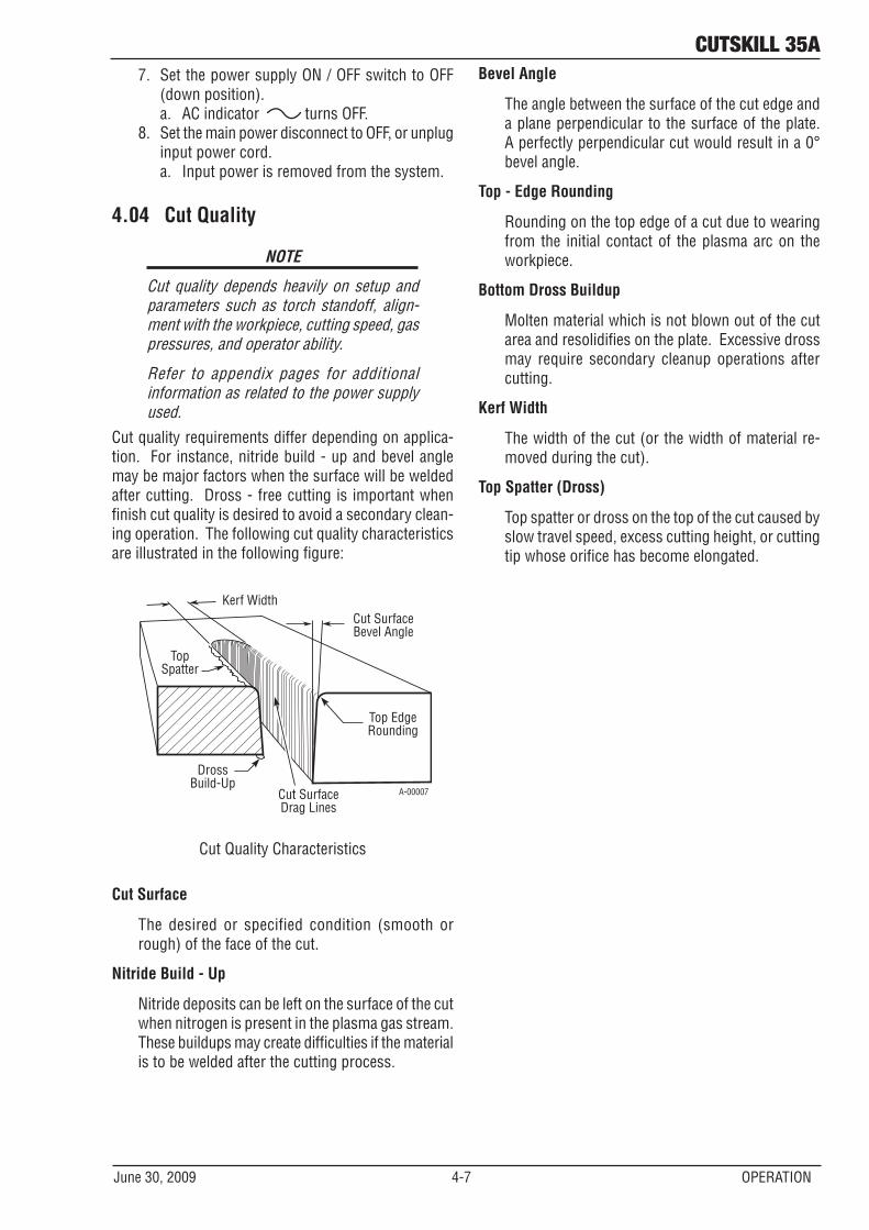
Cut quality requirements differ depending on applica-tion. For instance, nitride build - up and bevel angle may be major factors when the surface will be welded after cutting. Dross - free cutting is important when finish cut quality is desired to avoid a secondary clean-ing operation. The following cut quality characteristics are illustrated in the following figure:
Kerf WidthCut SurfaceBevel Angle
Top EdgeRounding
Cut SurfaceDrag Lines
DrossBuild-Up
TopSpatter
A-00007
Cut Quality Characteristics
Cut Surface
The desired or specified condition (smooth or rough) of the face of the cut.
Nitride Build - Up
Nitride deposits can be left on the surface of the cut when nitrogen is present in the plasma gas stream. These buildups may create difficulties if the material is to be welded after the cutting process.
Bevel Angle
The angle between the surface of the cut edge and a plane perpendicular to the surface of the plate. A perfectly perpendicular cut would result in a 0° bevel angle.
Top - Edge Rounding
Rounding on the top edge of a cut due to wearing from the initial contact of the plasma arc on the workpiece.
Bottom Dross Buildup
Molten material which is not blown out of the cut area and resolidifies on the plate. Excessive dross may require secondary cleanup operations after cutting.
Kerf Width
The width of the cut (or the width of material re-moved during the cut).
Top Spatter (Dross)
Top spatter or dross on the top of the cut caused by slow travel speed, excess cutting height, or cutting tip whose orifice has become elongated.
cutSKILL 35A
OPERATION 4-8 June 30, 2009
4.05 General Cutting Information
! WARNING
Disconnect primary power at the source be-fore disassembling the power supply, torch, or torch leads.
Frequently review the Important Safety Pre-cautions at the front of this manual. Be sure the operator is equipped with proper gloves, clothing, eye and ear protection. Make sure no part of the operator’s body comes into contact with the workpiece while the torch is activated.\
CAUTION
Sparks from the cutting process can cause damage to coated, painted, and other sur-faces such as glass, plastic and metal.
NOTE
Handle torch leads with care and protect them from damage.
Torch Standoff
Improper standoff (the distance between the torch tip and workpiece) can adversely affect tip life as well as shield cup life. Standoff may also signifi-cantly affect the bevel angle. Reducing standoff will generally result in a more square cut.
Edge Starting
For edge starts, hold the torch perpendicular to the workpiece with the front of the tip near (not touch-ing) the edge of the workpiece at the point where the cut is to start. When starting at the edge of the plate, do not pause at the edge and force the arc to "reach" for the edge of the metal. Establish the cutting arc as quickly as possible.
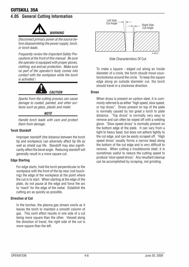
Direction of Cut
In the torches, the plasma gas stream swirls as it leaves the torch to maintain a smooth column of gas. This swirl effect results in one side of a cut being more square than the other. Viewed along the direction of travel, the right side of the cut is more square than the left.
Right SideCut Angle
Left SideCut Angle
A-00512
Side Characteristics Of Cut
To make a square - edged cut along an inside diameter of a circle, the torch should move coun-terclockwise around the circle. To keep the square edge along an outside diameter cut, the torch should travel in a clockwise direction.
Dross
When dross is present on carbon steel, it is com-monly referred to as either “high speed, slow speed, or top dross”. Dross present on top of the plate is normally caused by too great a torch to plate distance. "Top dross" is normally very easy to remove and can often be wiped off with a welding glove. "Slow speed dross" is normally present on the bottom edge of the plate. It can vary from a light to heavy bead, but does not adhere tightly to the cut edge, and can be easily scraped off. "High speed dross" usually forms a narrow bead along the bottom of the cut edge and is very difficult to remove. When cutting a troublesome steel, it is sometimes useful to reduce the cutting speed to produce "slow speed dross". Any resultant cleanup can be accomplished by scraping, not grinding.
cutskill 35a
June 30, 2009 5-1 SERVICE
SECTION 5 SYSTEM: SERVICE
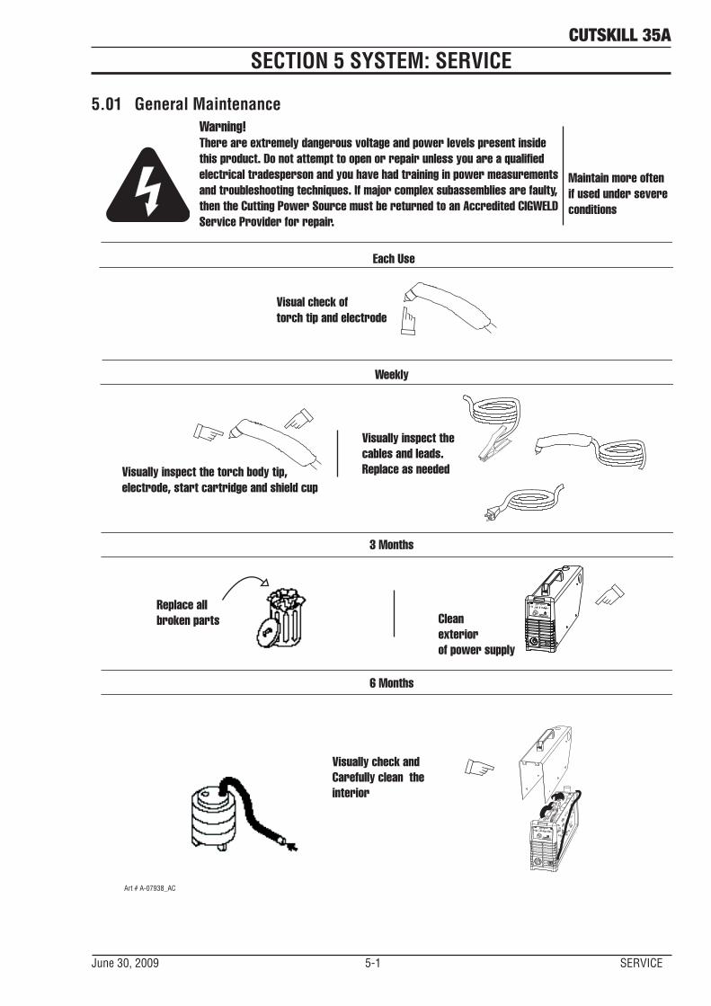
5.01 General MaintenanceWarning! There are extremely dangerous voltage and power levels present inside this product. Do not attempt to open or repair unless you are a qualifiedelectrical tradesperson and you have had training in power measurementsand troubleshooting techniques. If major complex subassemblies are faulty,then the Cutting Power Source must be returned to an Accredited CIGWELDService Provider for repair.
Each Use
Visual check oftorch tip and electrode
Weekly
Visually inspect the torch body tip, electrode, start cartridge and shield cup
Visually inspect thecables and leads.Replace as needed
3 Months
6 Months
Replace all broken parts
Visually check and Carefully clean the interior
Maintain more oftenif used under severeconditions
Art # A-07938_AC
RUN
SET
CURRENT (A)
25
35
READYAIR
OVERHEATPOWER
Cleanexteriorof power supply
RUN
SET
CURRENT (A)
25
35
READYAIR
OVERHEATPOWER
cutskill 35a
SERVICE 5-2 June 30, 2009
A. Every three months
Check external air filter, replace if necessary.
1. Shut off input power; turn off the gas supply. Bleed down the gas supply. Check air filter and replace if neces-sary.
NOTE
Leave internal ground wire in place.
B. Every six months
1. Check the in-line air filter(s), clean or replace as required.
2. Check cables and hoses for leaks or cracks, replace if necessary.
3. Check all contactor points for severe arcing or pits, replace if necessary.
4. Vacuum dust and dirt out of the entire machine.
5.02 Basic Troubleshooting Guide
! WARNING
There are extremely dangerous voltage and power levels present inside this unit. Do not attempt to diagnose or repair it unless you are an accredited service provider and you have had training in power electronics measurement and troubleshooting techniques.
1. Common Faults symptom
A. Gas regulator leakage 1) Gas regulator on a. Reset the regulator to 0 PSI and re-adjust it to 65 PSI (4.5 bar).
B. AC indicator OFF 1) Main input power cord does not connect to power distribution net. a. Connect the power cord. 2) Power ON/OFF switch in OFF (down) position. a. Turn switch to ON (up) position. 3) Actual input voltage does not correspond to voltage of unit. a. Verify that the input line voltage is correct. 4) Faulty components in unit a. Return for repair or have qualified technician repair per service manual.
C. Torch will not pilot; When trigger is activated, Air indicator ON. 1) Gas pressure too low. Adjust the pressure to 65 PSI/4.5 bar.
D. AC indicator ON, TEMP indicator ON. 1) Air flow blocked
a. Check for blocked air flow around the unit and correct condition.
2) Fan blocked a. Check for blocked status and correct condition. 3) Unit is overheated. a. Keep the machine plugged in and turned on for five minutes. This will allow
the fan to run and cool the machine.
cutskill 35a
June 30, 2009 5-3 SERVICE
4) Faulty components in unit a. Return for repair or have qualified technician repair per service manual.
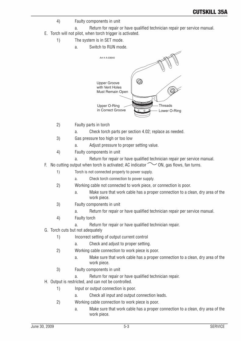
E. Torch will not pilot, when torch trigger is activated. 1) The system is in SET mode. a. Switch to RUN mode.
Lower O-RingUpper O-Ring in Correct Groove
Upper Groove with Vent Holes Must Remain Open
Threads
Art # A-03640
2) Faulty parts in torch a. Check torch parts per section 4.02; replace as needed. 3) Gas pressure too high or too low a. Adjust pressure to proper setting value. 4) Faulty components in unit a. Return for repair or have qualified technician repair per service manual.
F. No cutting output when torch is activated; AC indicator ON, gas flows, fan turns. 1) Torch is not connected properly to power supply.
a. Check torch connection to power supply.
2) Working cable not connected to work piece, or connection is poor. a. Make sure that work cable has a proper connection to a clean, dry area of the
work piece. 3) Faulty components in unit a. Return for repair or have qualified technician repair per service manual. 4) Faulty torch a. Return for repair or have qualified technician repair.
G. Torch cuts but not adequately 1) Incorrect setting of output current control a. Check and adjust to proper setting. 2) Working cable connection to work piece is poor. a. Make sure that work cable has a proper connection to a clean, dry area of the
work piece. 3) Faulty components in unit a. Return for repair or have qualified technician repair.
H. Output is restricted, and can not be controlled. 1) Input or output connection is poor. a. Check all input and output connection leads. 2) Working cable connection to work piece is poor. a. Make sure that work cable has a proper connection to a clean, dry area of the
work piece.
cutskill 35a
SERVICE 5-4 June 30, 2009
3) Faulty components in unit a. Return for repair or have qualified technician repair per service manual.
I. Cutting output is unstable or inadequate. 1) Input or output connection is poor a. Check all input and output connection leads. 2) Working cable connection is poor. a. Make sure that work cable has a proper connection to a clean, dry area of the
work piece. 3) Fluctuations in input power a. Have electrician check input line voltage.
J. Hard to startup 1) Torch parts worn (consumables) a. Turn off input power, remove shield cup, tip, start cartridge, and electrode
and check them all. If the electrode or cutting tip is worn out, replace them. If the start cartridge does not move freely, replace it. If there is too much spat- ter on shield cup, replace it.
K. Arc goes out while operating. Arc can’t be restarted when torch trigger is activated.
1) Power Supply is overheated (TEMP indicator ON). a. Let unit cool down for at least 5 minutes. Make sure the unit has not been
operated beyond duty cycle limit.
2) Fan blades blocked (TEMP indicator ON). a. Check and clear blades. 3) Air flow blocked a. Check for blocked air flow around the unit and correct condition.
4) Gas pressure is too low. (Air indicator ON when torch trigger is activated.) a. Check gas source, It should be set to at least 65 PSI/4.5 bar. Adjust it as
needed. 5) Torch parts worn a. Check torch shield cup, cutting tip, start cartridge and electrode. Replace as
needed. 6) Faulty component in unit a. Return for repair or have qualified technician repair per service manual.
L. Torch cuts but not well. 1) Current control is set too low. a. Increase the current setting. 2) Torch is being moved too fast across work piece a. Reduce cutting speed. 3) Excessive oil or moisture in torch a. Hold torch 1/8 inch (3 mm) from clean surface while purging and observe
oil or moisture buildup (do not activate torch). If there are contaminants in the gas, additional filtering may be needed.
cutskill 35A
June 30, 2009 5T-1 SERVICE
SECTION 5 TORCH: SERVICE
5T.01 General MaintenanceNOTE
Refer to Previous "Section 5 System" for common and fault indicator descriptions.
Cleaning Torch
Even if precautions are taken to use only clean air with a torch, eventually the inside of the torch be-comes coated with residue. This buildup can affect the arc initiation and the overall cut quality of the torch.
! WARNING
Disconnect primary power to the system before disassembling the torch or torch leads.
DO NOT touch any internal torch parts while the AC indicator light of the Power Supply is ON.
The inside of the torch should be cleaned with electri-cal contact cleaner using a cotton swab or soft wet rag. In severe cases, the torch can be removed from the leads and cleaned more thoroughly by pouring electrical contact cleaner into the torch and blowing it through with compressed air.
CAUTION
Dry the torch thoroughly before reinstall-ing..
5T.02 Inspection and Replacement of Consumable Torch Parts
! WARNING
Disconnect primary power to the system before disassembling the torch or torch leads.
DO NOT touch any internal torch parts while the AC indicator light of the Power Supply is ON.
Remove the consumable torch parts as follows:
NOTE
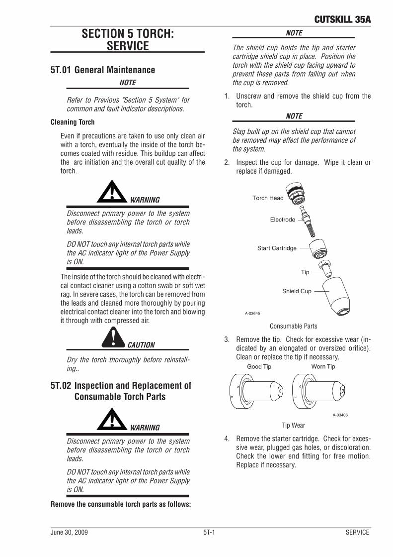
The shield cup holds the tip and starter cartridge shield cup in place. Position the torch with the shield cup facing upward to prevent these parts from falling out when the cup is removed.
1. Unscrew and remove the shield cup from the torch.
NOTE
Slag built up on the shield cup that cannot be removed may effect the performance of the system.
2. Inspect the cup for damage. Wipe it clean or replace if damaged.
A-03645
Electrode
Start Cartridge
Tip
Shield Cup
Torch Head
Consumable Parts
3. Remove the tip. Check for excessive wear (in-dicated by an elongated or oversized orifice). Clean or replace the tip if necessary.
Good Tip Worn Tip
A-03406
Tip Wear
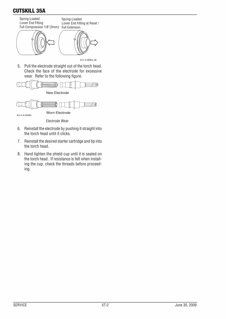
4. Remove the starter cartridge. Check for exces-sive wear, plugged gas holes, or discoloration. Check the lower end fitting for free motion. Replace if necessary.
cutskill 35A
SERVICE 5T-2 June 30, 2009
Art # A-08064_AB
Spring-Loaded Lower End FittingFull Compression 1/8”(3mm)
Spring-Loaded Lower End Fitting at Reset /Full Extension
5. Pull the electrode straight out of the torch head. Check the face of the electrode for excessive wear. Refer to the following figure.
Worn Electrode
New Electrode
Art # A-03284
Electrode Wear
6. Reinstall the electrode by pushing it straight into the torch head until it clicks.
7. Reinstall the desired starter cartridge and tip into the torch head.
8. Hand tighten the shield cup until it is seated on the torch head. If resistance is felt when install-ing the cup, check the threads before proceed-ing.
cutskill 35a
June 30, 2009 6-1 PART LISTE
SECTION 6: PARTS LISTS
6.01 Introduction
A. Parts List Breakdown
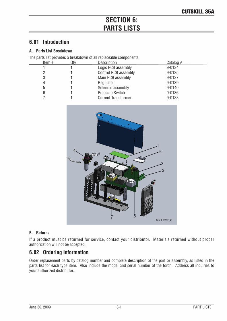
The parts list provides a breakdown of all replaceable components. Item # Qty Description Catalog # 1 1 Logic PCB assembly 9-0134 2 1 Control PCB assembly 9-0135 3 1 Main PCB assembly 9-0137 4 1 Regulator 9-0139 5 1 Solenoid assembly 9-0140 6 1 Pressure Switch 9-0136 7 1 Current Transformer 9-0138
1
3
4
2
5Art # A-09192_AB
6
7
B. Returns
If a product must be returned for service, contact your distributor. Materials returned without proper authorization will not be accepted.
6.02 Ordering InformationOrder replacement parts by catalog number and complete description of the part or assembly, as listed in the parts list for each type item. Also include the model and serial number of the torch. Address all inquiries to your authorized distributor.

This page left blank intentionally.
A-1 Appendix June 30, 2009
cutskill 35a
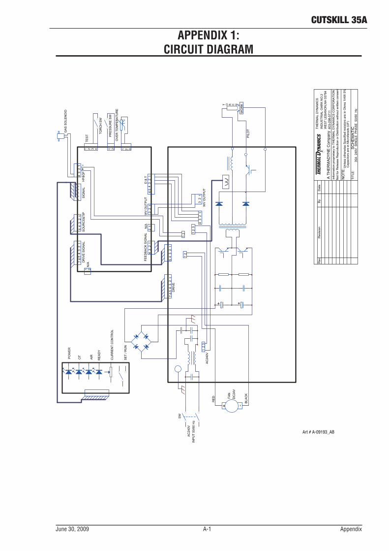
APPENDIX 1: CIRCUIT DIAGRAM
603-
298-
5711
THER
MAL
DYN
AMIC
SIN
DU
STR
IAL
OAR
K N
O.2
WES
T LE
BAN
ON
,NH
037
84A
TH
ER
MA
DY
NE
Com
pany
Info
rmat
ion
prop
rieta
ry to
TH
ER
MA
L D
YN
AM
ICS
CO
RP
OR
ATI
ON
Not
for R
elea
se R
epro
duct
ion
or D
istri
butio
n w
ithou
t writ
ten
cons
ent
NO
TE: U
nles
s ot
herw
ise
Spe
cifie
d re
sist
ors
are
in O
hms
1/4W
5%
Cap
acito
rs a
re in
Mic
rofa
rads
(UF)
TITL
E:
SC
HE
MA
TIC
35A
240
V S
ING
LE P
HA
SE
50/
60 H
z
Dat
eB
yR
evR
evis
ion
PIL
OT
WO
RKT O R C H
WV
OU
TPU
T
BLA
CK
RE
D
FAN
DC
24V
AC
240V
INP
UT
50/6
0 H
z
AC
240V
D &
TW
V O
UTP
UT
FEE
DB
AC
K S
IGN
AL
N/A
DR
IVE
PO
WE
R
OT
AIR
RE
AD
Y
CU
RR
EN
T C
ON
TRO
L
SE
T / R
UN
DR
IVE
SIG
NA
LN
/AS
OU
RC
E&
TIP
SIG
NA
LH
F&Q
F
GA
S S
OLE
NO
ID
TES
T
TOR
CH
SW
PR
ES
SU
RE
SW
OV
ER
TE
MP
ER
ATU
RE
1 2 3
12
3
1 21 2 3 4
12
34
12
34
51
23
45
67
1 2
12
34
12
12
31
23
45
6
12
31
23
4
12
12
34
51
23
45
67
12
SW
12
3
+
-
+ -
+ +
Art # A-09193_AB

This page left blank intentionally.

Thermadyne USA2800 Airport RoadDenton, Tx 76207 USATelephone: (940) 566-2000800-426-1888Fax: 800-535-0557
Thermadyne Canada2070 Wyecroft RoadOakville, OntarioCanada, L6L5V6Telephone: (905)-827-1111Fax: 905-827-3648
Thermadyne EuropeEurope BuildingChorley North Industrial ParkChorley, LancashireEngland, PR6 7BxTelephone: 44-1257-261755Fax: 44-1257-224800
Thermadyne, ChinaRM 102A685 Ding Xi RdChang Ning DistrictShanghai, PR, 200052Telephone: 86-21-69171135Fax: 86-21-69171139
Thermadyne, Utama Indonesia
Kawasan Industri JababekaJI Jababeka VI Blok P No.3Cikarang-Bekasi, 17550IndonesiaTelephone: 62-21-8936071Fax: 62-21-8936067/6068http://www.thermadyne.com
Thermadyne Asia Sdn BhdLot 151, Jalan Industri 3/5ARawang Integrated Industrial Park - Jln Batu Arang48000 Rawang Selangor Darul EhsanWest MalaysiaTelephone: 603+ 6092 2988Fax : 603+ 6092 1085
Thermadyne, Australia71 Gower StreetPreston, VictoriaAustralia, 3072Telephone: 61-3-9474-7400Fax: 61-3-9474-7510
Thermadyne ItalyOCIM, S.r.L.Via Benaco, 320098 S. GiulianoMilan, ItalyTel: (39) 02-98 80320Fax: (39) 02-98 281773
Thermadyne International2070 Wyecroft RoadOakville, OntarioCanada, L6L5V6Telephone: (905)-827-9777Fax: 905-827-9797
GLOBAL CUSTOMER SERVICE CONTACT

Asia Pacific Regional Headquarters71 Gower StreetPreston, Victoria, Australia, 3072Telephone: +61 3 9474 7400Fax: +61 3 9474 7488Email: [email protected]