research on electro hydraulic composite brake system
TRANSCRIPT
Research on Electro Hydraulic CompositeBrake System
Qinghe Liu, Lan Zhan and Ti He
Abstract This paper describes a proposal of electro hydraulic composite brakesystem, which is based on the high-speed switching valve, and sets up a algorithmof the composite braking resistance distribution, according to the law of ECE andmotor’s external characteristic. By using the simulator ADVISOR, the algorithm isanalyzed. The result shows that this algorithm can realize the braking safetyprimly, at the same time, recuperates energy of 220 kJ, leading to a 0.75 %increase of battery status.
Keywords Composite brake system � Brake resistance distribution � Brakingenergy regeneration � Braking safety � ECE law
1 Technical Paper: Introduction
Since the 21st century, faced with the much more serious problems of energyexhaustion and environmental pollution, many car-producing countries have beencontrolling the polluting emissions and fuel economy of their vehicles by setting
F2012-D01-003
Q. Liu � L. Zhan (&)Harbin Institute of Technology, Weihai, Chinae-mail: [email protected]
Q. Liue-mail: [email protected]
T. HeWeihai Xili Electronics LTD, Weihai, Chinae-mail: [email protected]
SAE-China and FISITA (eds.), Proceedings of the FISITA 2012 WorldAutomotive Congress, Lecture Notes in Electrical Engineering 194,DOI: 10.1007/978-3-642-33829-8_2, � Springer-Verlag Berlin Heidelberg 2013
13
more strict standards. Therefore, it brings the new energy vehicle, which canregenerate energy while braking, to public focus.
Regenerative braking system reserves part of the braking energy for driving thevehicles, which can increase vehicle economy effectively. But the effect ofregenerating energy is decided by the certain algorithm of the composite brakingforce distribution. Because the traditional braking system cannot realize inde-pendent and variable control of the hydraulic braking force, many complexalgorithms, which have strict requirements for the control of the hydraulic brakingforce, can not be applied to real cars. This traditional system limits the regener-ative efficiency of braking energy and the improvement of braking safety.However, the electro hydraulic composite brake system provides a practical way tosolve this problem.
In this study, we aim to research on the electro hydraulic composite brakesystem. Based on the high-speed switching valve, a proposal of this system, whichprovides a foundation for the following study, is raised. According to the law ofECE and motor’s external characteristic, we set up an algorithm of the compositebraking force distribution. Finally, by using the simulator ADVISOR, this algo-rithm is analyzed, from the perspectives of energy regeneration and braking safety.The ultimate result shows that this algorithm of the composite braking forcedistribution is superior in both of the aspects.
2 Structural Concept of the Composite Electro HydraulicBrake System
During the composite braking process, in order to realize active control of thehydraulic braking force, the electro hydraulic brake system should contain thefollowing basic functions.
1. The electro hydraulic composite brake system should have similar pedal feelingwith the traditional ones.
2. According to the master controller’s requirements of the composite brakesystem, this system should have the active ability to increase and decrease thepressure of the hydraulic brake system. Hydraulic brake should be separatedwith pedal operation.
After the functional analyses of the composite brake system and the electrohydraulic brake system, we raise a proposal of the electro hydraulic compositebrake system (Fig. 1), which is based on the high-speed switching valve. The mostobvious attribute of this proposal is that it can satisfy the requirements of variesalgorithms of the composite braking force distribution toward exact control of thehydraulic braking force [1].
Attributes of the proposal:
14 Q. Liu et al.
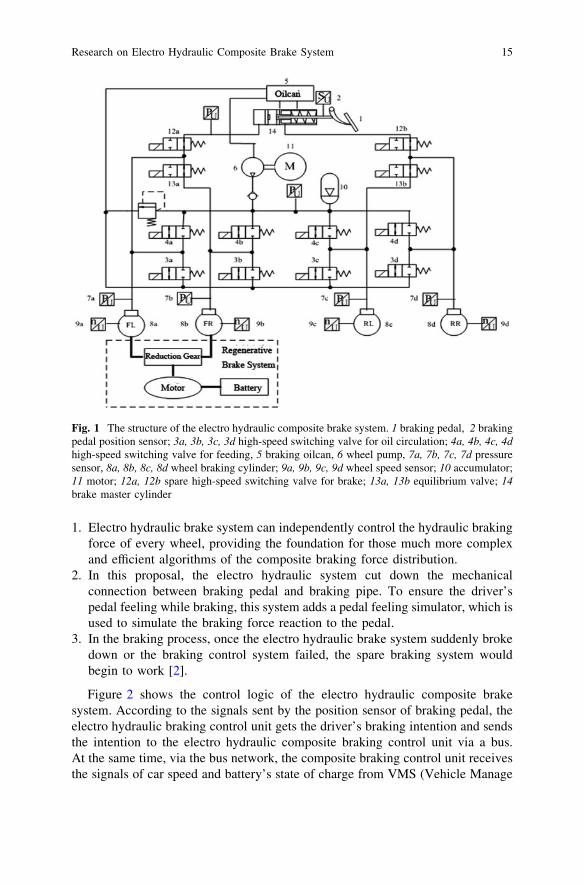
1. Electro hydraulic brake system can independently control the hydraulic brakingforce of every wheel, providing the foundation for those much more complexand efficient algorithms of the composite braking force distribution.
2. In this proposal, the electro hydraulic system cut down the mechanicalconnection between braking pedal and braking pipe. To ensure the driver’spedal feeling while braking, this system adds a pedal feeling simulator, which isused to simulate the braking force reaction to the pedal.
3. In the braking process, once the electro hydraulic brake system suddenly brokedown or the braking control system failed, the spare braking system wouldbegin to work [2].
Figure 2 shows the control logic of the electro hydraulic composite brakesystem. According to the signals sent by the position sensor of braking pedal, theelectro hydraulic braking control unit gets the driver’s braking intention and sendsthe intention to the electro hydraulic composite braking control unit via a bus.At the same time, via the bus network, the composite braking control unit receivesthe signals of car speed and battery’s state of charge from VMS (Vehicle Manage
Fig. 1 The structure of the electro hydraulic composite brake system. 1 braking pedal, 2 brakingpedal position sensor; 3a, 3b, 3c, 3d high-speed switching valve for oil circulation; 4a, 4b, 4c, 4dhigh-speed switching valve for feeding, 5 braking oilcan, 6 wheel pump, 7a, 7b, 7c, 7d pressuresensor, 8a, 8b, 8c, 8d wheel braking cylinder; 9a, 9b, 9c, 9d wheel speed sensor; 10 accumulator;11 motor; 12a, 12b spare high-speed switching valve for brake; 13a, 13b equilibrium valve; 14brake master cylinder
Research on Electro Hydraulic Composite Brake System 15
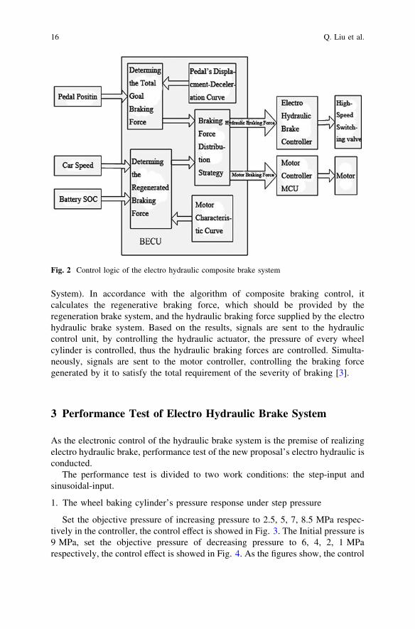
System). In accordance with the algorithm of composite braking control, itcalculates the regenerative braking force, which should be provided by theregeneration brake system, and the hydraulic braking force supplied by the electrohydraulic brake system. Based on the results, signals are sent to the hydrauliccontrol unit, by controlling the hydraulic actuator, the pressure of every wheelcylinder is controlled, thus the hydraulic braking forces are controlled. Simulta-neously, signals are sent to the motor controller, controlling the braking forcegenerated by it to satisfy the total requirement of the severity of braking [3].
3 Performance Test of Electro Hydraulic Brake System
As the electronic control of the hydraulic brake system is the premise of realizingelectro hydraulic brake, performance test of the new proposal’s electro hydraulic isconducted.
The performance test is divided to two work conditions: the step-input andsinusoidal-input.
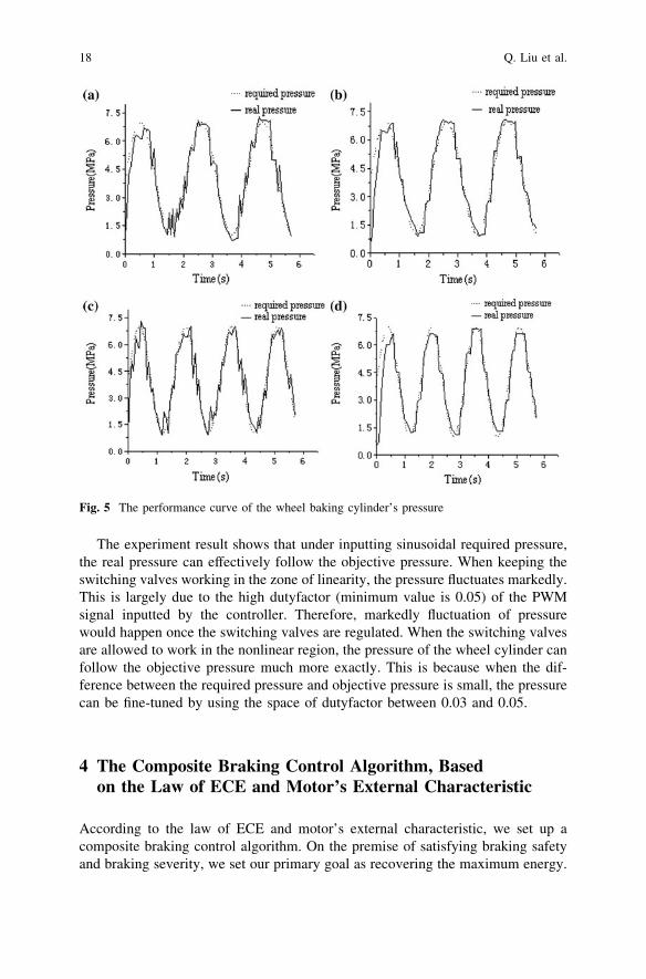
1. The wheel baking cylinder’s pressure response under step pressure
Set the objective pressure of increasing pressure to 2.5, 5, 7, 8.5 MPa respec-tively in the controller, the control effect is showed in Fig. 3. The Initial pressure is9 MPa, set the objective pressure of decreasing pressure to 6, 4, 2, 1 MParespectively, the control effect is showed in Fig. 4. As the figures show, the control
Fig. 2 Control logic of the electro hydraulic composite brake system
16 Q. Liu et al.
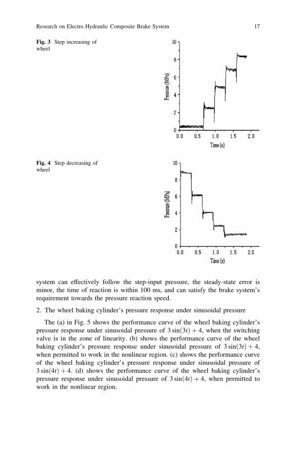
system can effectively follow the step-input pressure, the steady-state error isminor, the time of reaction is within 100 ms, and can satisfy the brake system’srequirement towards the pressure reaction speed.
2. The wheel baking cylinder’s pressure response under sinusoidal pressure
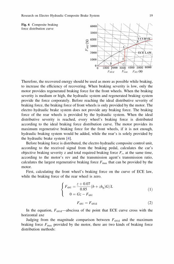
The (a) in Fig. 5 shows the performance curve of the wheel baking cylinder’spressure response under sinusoidal pressure of 3 sinð3tÞ þ 4, when the switchingvalve is in the zone of linearity. (b) shows the performance curve of the wheelbaking cylinder’s pressure response under sinusoidal pressure of 3 sinð3tÞ þ 4,when permitted to work in the nonlinear region. (c) shows the performance curveof the wheel baking cylinder’s pressure response under sinusoidal pressure of3 sinð4tÞ þ 4. (d) shows the performance curve of the wheel baking cylinder’spressure response under sinusoidal pressure of 3 sinð4tÞ þ 4, when permitted towork in the nonlinear region.
Fig. 3 Step increasing ofwheel
Fig. 4 Step decreasing ofwheel
Research on Electro Hydraulic Composite Brake System 17
The experiment result shows that under inputting sinusoidal required pressure,the real pressure can effectively follow the objective pressure. When keeping theswitching valves working in the zone of linearity, the pressure fluctuates markedly.This is largely due to the high dutyfactor (minimum value is 0.05) of the PWMsignal inputted by the controller. Therefore, markedly fluctuation of pressurewould happen once the switching valves are regulated. When the switching valvesare allowed to work in the nonlinear region, the pressure of the wheel cylinder canfollow the objective pressure much more exactly. This is because when the dif-ference between the required pressure and objective pressure is small, the pressurecan be fine-tuned by using the space of dutyfactor between 0.03 and 0.05.
4 The Composite Braking Control Algorithm, Basedon the Law of ECE and Motor’s External Characteristic
According to the law of ECE and motor’s external characteristic, we set up acomposite braking control algorithm. On the premise of satisfying braking safetyand braking severity, we set our primary goal as recovering the maximum energy.
Fig. 5 The performance curve of the wheel baking cylinder’s pressure
18 Q. Liu et al.
Therefore, the recovered energy should be used as more as possible while braking,to increase the efficiency of recovering. When braking severity is low, only themotor provides regenerated braking force for the front wheels. When the brakingseverity is medium or high, the hydraulic system and regenerated braking systemprovide the force corporately. Before reaching the ideal distributive severity ofbraking force, the braking force of front wheels is only provided by the motor. Theelectro hydraulic brake system does not provide any braking force. The brakingforce of the rear wheels is provided by the hydraulic system. When the idealdistributive severity is reached, every wheel’s braking force is distributedaccording to the ideal braking force distribution curve. The motor provides itsmaximum regenerative braking force for the front wheels, if it is not enough,hydraulic braking system would be added, while the rear’s is solely provided bythe hydraulic brake system [4].
Before braking force is distributed, the electro hydraulic composite control unit,according to the received signal from the braking pedal, calculates the car’sobjective braking severity z and total required braking force Fr, at the same time,according to the motor’s rev and the transmission agent’s transmission ratio,calculates the largest regenerative braking force Fmax that can be provided by themotor.
First, calculating the front wheel’s braking force on the curve of ECE law,while the braking force of the rear wheel is zero.
Fxb1 ¼zþ 0:07
0:85ðbþ zhgÞG=L
0 ¼ Gz� Fxb1
8<
:ð1Þ
Fxb1 ¼ Fxb1d ð2Þ
In the equation, Fxb1d—abscissa of the point that ECE curve cross with thehorizontal axe
Judging from the magnitude comparison between Fxb1d and the maximumbraking force Fmax provided by the motor, there are two kinds of braking forcedistribution methods:
Fig. 6 Composite brakingforce distribution curve
Research on Electro Hydraulic Composite Brake System 19
When Fmax [ Fxb1d, the braking force distribution is the ODEAB curve(Fig. 6, [5])
(1) z� zD, total regenerative braking section.
Fm ¼ Fr; Fhf ¼ 0; Fhr ¼ 0
In the equation,Fm motor’s regenerative braking force (N);Fhf front wheels’ hydraulic braking force (N);Fhr rear wheels’ hydraulic braking force (N).
(2) zD\z� zE, braking force distribution changes along the curve of ECE law
Fm ¼z þ 0:07
0:85ðbþ zhgÞG=L;Fhf ¼ 0;Fhr ¼ Fr � Fm
(3) zE\z� zA, motor provides the maximum braking force
Fm ¼ Fmax;Fhf ¼ 0;Fhr ¼ Fr � Fmax
(4) z [ zA, braking force distribution changes along curve I
Fm ¼ Fmax;Fhf ¼ Frbþ hgFr=G
L� Fm;Fhr ¼ Fr
a� hgFr=G
L
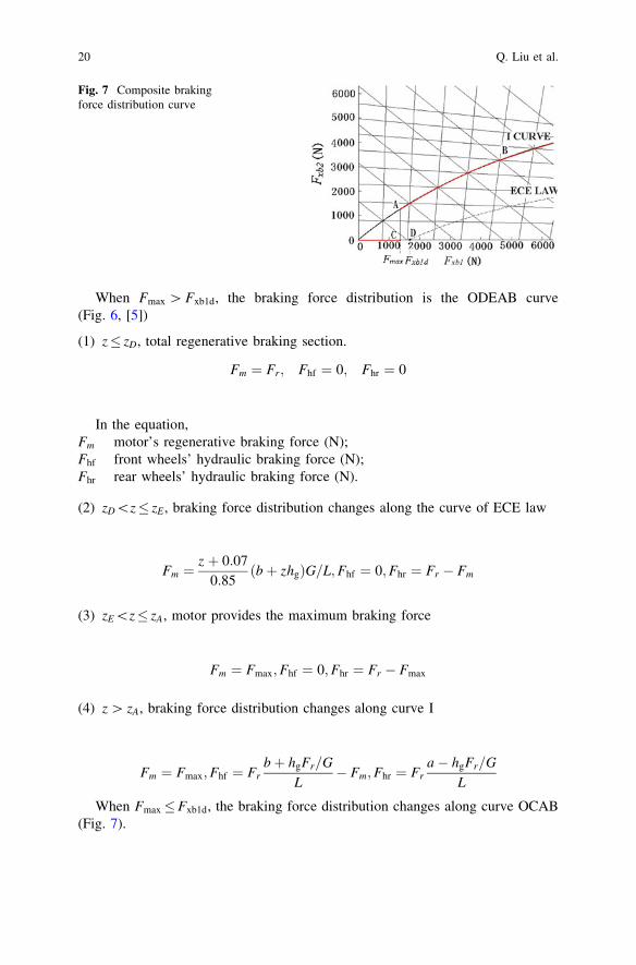
When Fmax�Fxb1d, the braking force distribution changes along curve OCAB(Fig. 7).
Fig. 7 Composite brakingforce distribution curve
20 Q. Liu et al.
(1) z� zC, total regenerative braking section, braking force only provided by themotor.
Fm ¼ Fr; Fhf ¼ 0; Fhr ¼ 0
(2) zC\z� zA, motor provides the maximum braking force
Fm ¼ Fmax;Fhf ¼ o;Fhr ¼ Fr � Fmax
(3) z [ zA, braking force distribution changes along curve I
Fm ¼ Fmax;Fhf ¼ Frbþ hgFr=G
L� Fm;Fhr ¼ Fr
a� hgFr=G
L
5 Simulation of the Electro Hydraulic Composite BrakingStrategy
5.1 Building of the Simulative Model
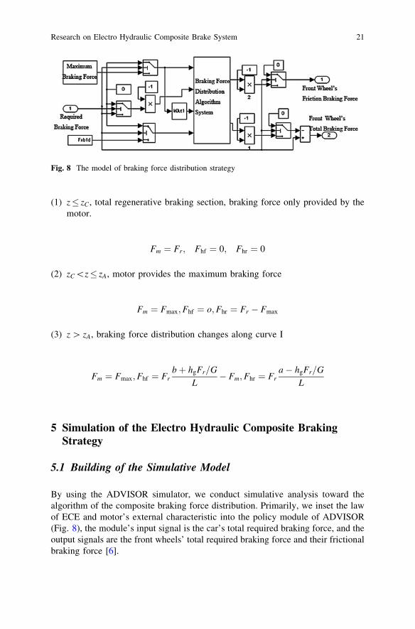
By using the ADVISOR simulator, we conduct simulative analysis toward thealgorithm of the composite braking force distribution. Primarily, we inset the lawof ECE and motor’s external characteristic into the policy module of ADVISOR(Fig. 8), the module’s input signal is the car’s total required braking force, and theoutput signals are the front wheels’ total required braking force and their frictionalbraking force [6].
Fig. 8 The model of braking force distribution strategy
Research on Electro Hydraulic Composite Brake System 21
Using the models of every assembled vehicle element in ADVISOR, someassembled m documents are modified necessarily. For example, it happens whenselecting transmission ratio of driving chain, we try to make the motor work in thezone of high efficiency and high torquemoment, however, we also have to makesure that transmission is fixed in the certain gear when braking.
5.2 Analysis of the Simulation Result
In a process of slow braking, to test the rationality and validity of the braking forcedistribution algorithm, we simulate the distribution of the car’s braking force, thesituation of the wheel’s motion and energy regeneration, to test the rationality andvalidity of the braking force distribution algorithm.
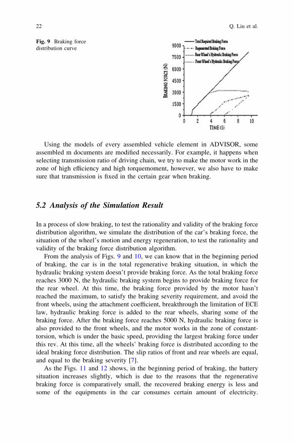
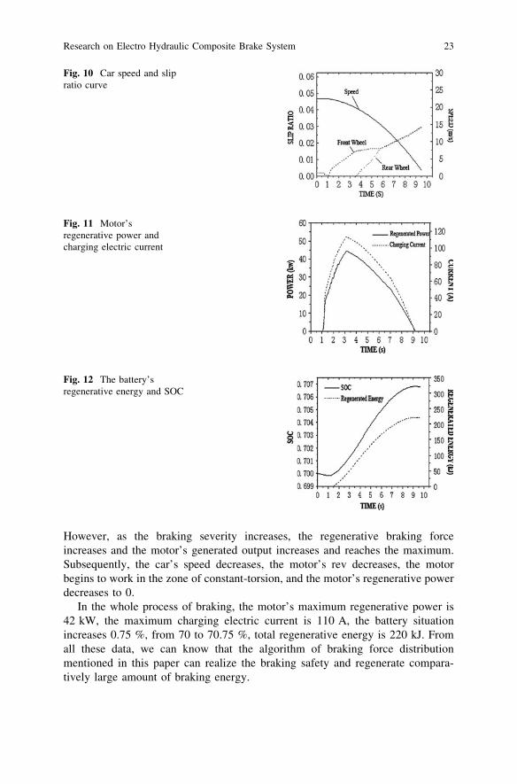
From the analysis of Figs. 9 and 10, we can know that in the beginning periodof braking, the car is in the total regenerative braking situation, in which thehydraulic braking system doesn’t provide braking force. As the total braking forcereaches 3000 N, the hydraulic braking system begins to provide braking force forthe rear wheel. At this time, the braking force provided by the motor hasn’treached the maximum, to satisfy the braking severity requirement, and avoid thefront wheels, using the attachment coefficient, breakthrough the limitation of ECElaw, hydraulic braking force is added to the rear wheels, sharing some of thebraking force. After the braking force reaches 5000 N, hydraulic braking force isalso provided to the front wheels, and the motor works in the zone of constant-torsion, which is under the basic speed, providing the largest braking force underthis rev. At this time, all the wheels’ braking force is distributed according to theideal braking force distribution. The slip ratios of front and rear wheels are equal,and equal to the braking severity [7].
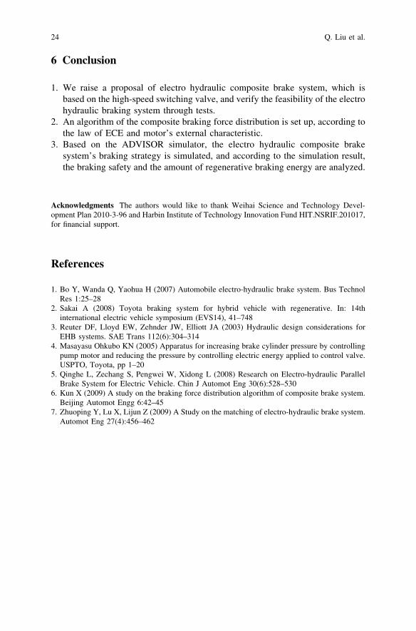
As the Figs. 11 and 12 shows, in the beginning period of braking, the batterysituation increases slightly, which is due to the reasons that the regenerativebraking force is comparatively small, the recovered braking energy is less andsome of the equipments in the car consumes certain amount of electricity.
Fig. 9 Braking forcedistribution curve
22 Q. Liu et al.
However, as the braking severity increases, the regenerative braking forceincreases and the motor’s generated output increases and reaches the maximum.Subsequently, the car’s speed decreases, the motor’s rev decreases, the motorbegins to work in the zone of constant-torsion, and the motor’s regenerative powerdecreases to 0.
In the whole process of braking, the motor’s maximum regenerative power is42 kW, the maximum charging electric current is 110 A, the battery situationincreases 0.75 %, from 70 to 70.75 %, total regenerative energy is 220 kJ. Fromall these data, we can know that the algorithm of braking force distributionmentioned in this paper can realize the braking safety and regenerate compara-tively large amount of braking energy.
Fig. 10 Car speed and slipratio curve
Fig. 11 Motor’sregenerative power andcharging electric current
Fig. 12 The battery’sregenerative energy and SOC
Research on Electro Hydraulic Composite Brake System 23
6 Conclusion
1. We raise a proposal of electro hydraulic composite brake system, which isbased on the high-speed switching valve, and verify the feasibility of the electrohydraulic braking system through tests.
2. An algorithm of the composite braking force distribution is set up, according tothe law of ECE and motor’s external characteristic.
3. Based on the ADVISOR simulator, the electro hydraulic composite brakesystem’s braking strategy is simulated, and according to the simulation result,the braking safety and the amount of regenerative braking energy are analyzed.
Acknowledgments The authors would like to thank Weihai Science and Technology Devel-opment Plan 2010-3-96 and Harbin Institute of Technology Innovation Fund HIT.NSRIF.201017,for financial support.
References
1. Bo Y, Wanda Q, Yaohua H (2007) Automobile electro-hydraulic brake system. Bus TechnolRes 1:25–28
2. Sakai A (2008) Toyota braking system for hybrid vehicle with regenerative. In: 14thinternational electric vehicle symposium (EVS14), 41–748
3. Reuter DF, Lloyd EW, Zehnder JW, Elliott JA (2003) Hydraulic design considerations forEHB systems. SAE Trans 112(6):304–314
4. Masayasu Ohkubo KN (2005) Apparatus for increasing brake cylinder pressure by controllingpump motor and reducing the pressure by controlling electric energy applied to control valve.USPTO, Toyota, pp 1–20
5. Qinghe L, Zechang S, Pengwei W, Xidong L (2008) Research on Electro-hydraulic ParallelBrake System for Electric Vehicle. Chin J Automot Eng 30(6):528–530
6. Kun X (2009) A study on the braking force distribution algorithm of composite brake system.Beijing Automot Engg 6:42–45
7. Zhuoping Y, Lu X, Lijun Z (2009) A Study on the matching of electro-hydraulic brake system.Automot Eng 27(4):456–462
24 Q. Liu et al.

http://www.springer.com/978-3-642-33828-1