research & development, fea, cfd, electro-chemical etching ...electro-chemical etching &...
TRANSCRIPT
© Continuum Blue Ltd.
Research & Development, FEA, CFD,
Material Selection, Testing & Assessment
Electro-Chemical Etching & Deposition of a Super Alloy Using Tertiary Current
Distribution Method
Mark S Yeoman1 & R Damodharan1
1. Continuum Blue Ltd., United Kingdom.
R&D, FEA, CFD, Material Selection, Testing & Assessment © Continuum Blue Ltd
OVERVIEW
• Introduction to Electrochemical Machining process
• Types
• Process involved & parameters
• Application & industries
• Model overview
• Model variables
• Physics- Electrochemical
• Physics- Electrode kinematics & parameters
• Mesh
• Results
R&D, FEA, CFD, Material Selection, Testing & Assessment © Continuum Blue Ltd
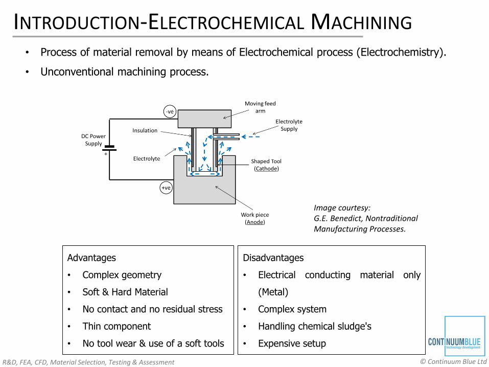
INTRODUCTION-ELECTROCHEMICAL MACHINING
• Process of material removal by means of Electrochemical process (Electrochemistry).
• Unconventional machining process.
Image courtesy: G.E. Benedict, NontraditionalManufacturing Processes.
Advantages
• Complex geometry
• Soft & Hard Material
• No contact and no residual stress
• Thin component
• No tool wear & use of a soft tools
Disadvantages
• Electrical conducting material only
(Metal)
• Complex system
• Handling chemical sludge's
• Expensive setup
R&D, FEA, CFD, Material Selection, Testing & Assessment © Continuum Blue Ltd
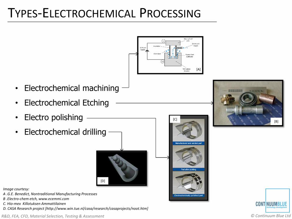
TYPES-ELECTROCHEMICAL PROCESSING
• Electrochemical machining
• Electrochemical Etching
• Electro polishing
• Electrochemical drilling
[B]
Image courtesy: A .G.E. Benedict, Nontraditional Manufacturing ProcessesB .Electro-chem etch, www.ecemmi.comC. Hio-mex Killotuksen AmmattilainenD. CASA Research project [http://www.win.tue.nl/casa/research/casaprojects/noot.htm]
[A]
[C]
[D]

R&D, FEA, CFD, Material Selection, Testing & Assessment © Continuum Blue Ltd
PROCESS-ELECTROCHEMICAL PROCESSING
• Multiphysics process
• Coupled interaction between different physical and chemical
phenomena.
• Describe very well in R. van Tijum & T. Pajak paper[2]
Image courtesy: R.van Tjium & T. Pajak paper[2]
R&D, FEA, CFD, Material Selection, Testing & Assessment © Continuum Blue Ltd
APPLICATION-ELECTROCHEMICAL PROCESSING
1. Aviation
2. Automobile
3. Medical
4. Consumer Products
5. Manufacturing
6. Nuclear
7. Fashion
R&D, FEA, CFD, Material Selection, Testing & Assessment © Continuum Blue Ltd
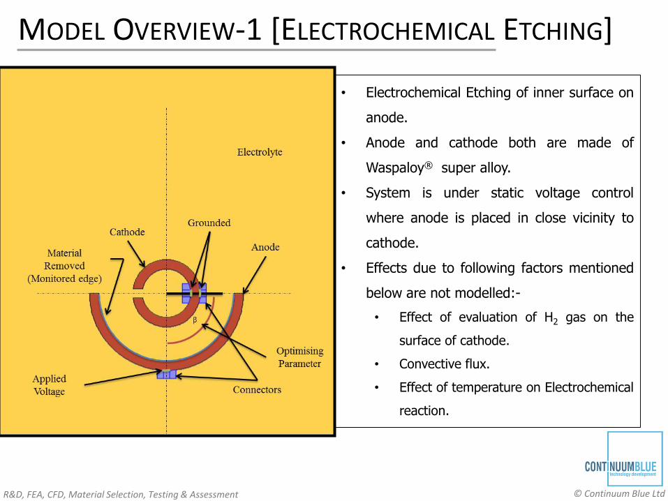
MODEL OVERVIEW-1 [ELECTROCHEMICAL ETCHING]
• Electrochemical Etching of inner surface on
anode.
• Anode and cathode both are made of
Waspaloy® super alloy.
• System is under static voltage control
where anode is placed in close vicinity to
cathode.
• Effects due to following factors mentioned
below are not modelled:-
• Effect of evaluation of H2 gas on the
surface of cathode.
• Convective flux.
• Effect of temperature on Electrochemical
reaction.
R&D, FEA, CFD, Material Selection, Testing & Assessment © Continuum Blue Ltd
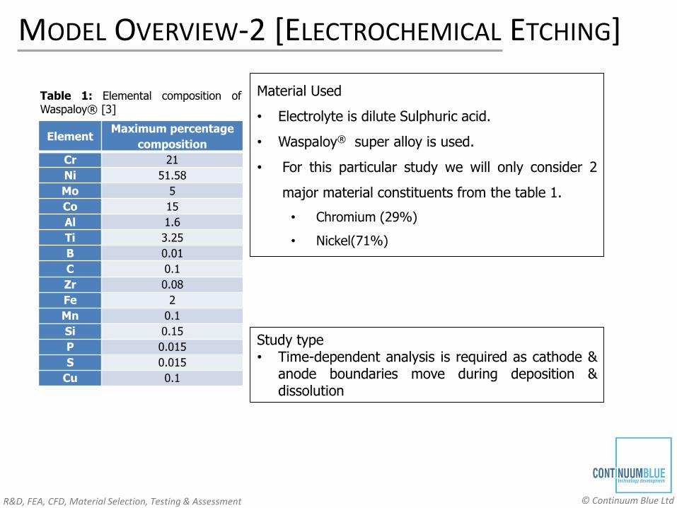
MODEL OVERVIEW-2 [ELECTROCHEMICAL ETCHING]
ElementMaximum percentage
composition
Cr 21
Ni 51.58
Mo 5
Co 15
Al 1.6
Ti 3.25
B 0.01
C 0.1
Zr 0.08
Fe 2
Mn 0.1
Si 0.15
P 0.015
S 0.015
Cu 0.1
Table 1: Elemental composition ofWaspaloy® [3]
Material Used
• Electrolyte is dilute Sulphuric acid.
• Waspaloy® super alloy is used.
• For this particular study we will only consider 2
major material constituents from the table 1.
• Chromium (29%)
• Nickel(71%)
Study type• Time-dependent analysis is required as cathode &
anode boundaries move during deposition &dissolution
R&D, FEA, CFD, Material Selection, Testing & Assessment © Continuum Blue Ltd
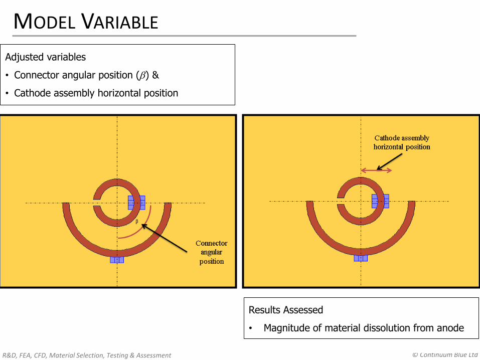
MODEL VARIABLE
Adjusted variables
• Connector angular position () &
• Cathode assembly horizontal position
Results Assessed
• Magnitude of material dissolution from anode
R&D, FEA, CFD, Material Selection, Testing & Assessment © Continuum Blue Ltd
PHYSICS-ELECTROCHEMISTRY 1
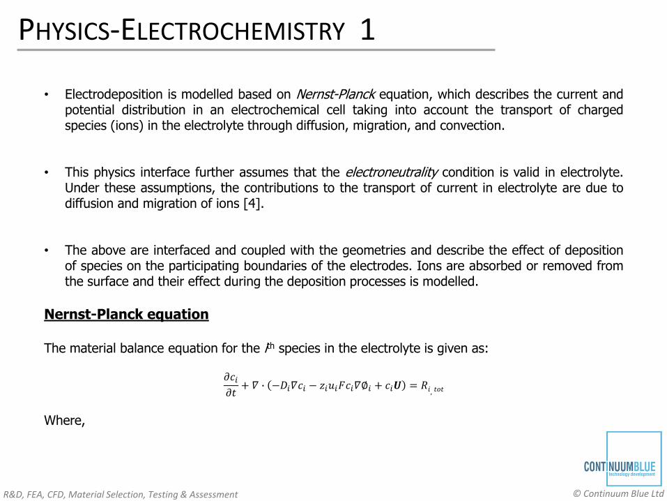
• Electrodeposition is modelled based on Nernst-Planck equation, which describes the current andpotential distribution in an electrochemical cell taking into account the transport of chargedspecies (ions) in the electrolyte through diffusion, migration, and convection.
• This physics interface further assumes that the electroneutrality condition is valid in electrolyte.Under these assumptions, the contributions to the transport of current in electrolyte are due todiffusion and migration of ions [4].
• The above are interfaced and coupled with the geometries and describe the effect of depositionof species on the participating boundaries of the electrodes. Ions are absorbed or removed fromthe surface and their effect during the deposition processes is modelled.
Nernst-Planck equation
The material balance equation for the ith species in the electrolyte is given as:
𝜕𝑐𝑖𝜕𝑡+ 𝛻 ∙ −𝐷𝑖𝛻𝑐𝑖 − 𝑧𝑖𝑢𝑖𝐹𝑐𝑖𝛻∅𝑖 + 𝑐𝑖𝑼 = 𝑅𝑖, 𝑡𝑜𝑡
Where,
R&D, FEA, CFD, Material Selection, Testing & Assessment © Continuum Blue Ltd
PHYSICS-ELECTROCHEMISTRY 2
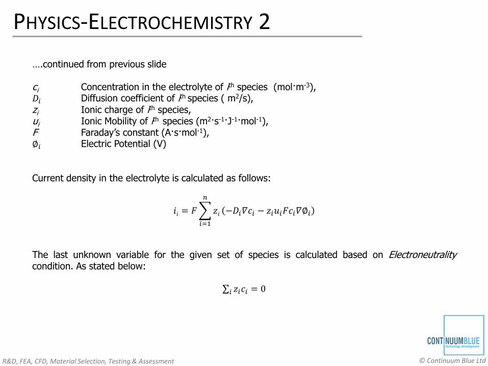
….continued from previous slide
ci Concentration in the electrolyte of ith species (mol·m-3),𝐷𝑖 Diffusion coefficient of ith species ( m2/s), zi Ionic charge of ith species,ui Ionic Mobility of ith species (m2·s-1·J-1·mol-1),F Faraday’s constant (A·s·mol-1),∅𝑖 Electric Potential (V)
Current density in the electrolyte is calculated as follows:
𝑖𝑖 = 𝐹
𝑖=1
𝑛
𝑧𝑖 −𝐷𝑖𝛻𝑐𝑖 − 𝑧𝑖𝑢𝑖𝐹𝑐𝑖𝛻∅𝑖
The last unknown variable for the given set of species is calculated based on Electroneutralitycondition. As stated below:
𝑖 𝑧𝑖𝑐𝑖 = 0
R&D, FEA, CFD, Material Selection, Testing & Assessment © Continuum Blue Ltd
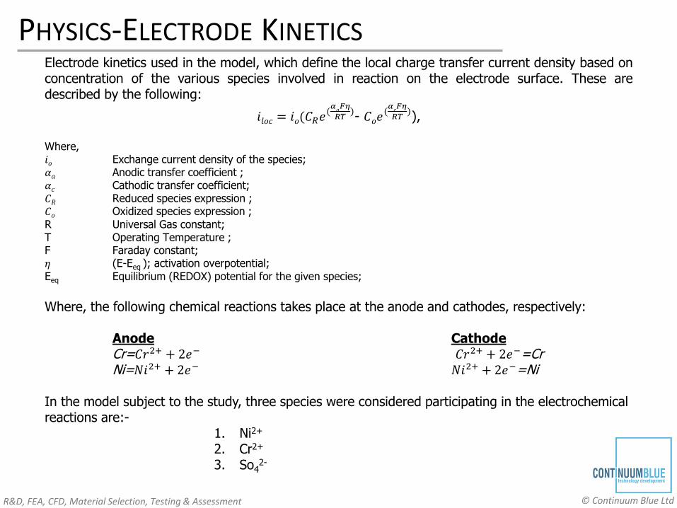
PHYSICS-ELECTRODE KINETICSElectrode kinetics used in the model, which define the local charge transfer current density based onconcentration of the various species involved in reaction on the electrode surface. These aredescribed by the following:
𝑖𝑙𝑜𝑐 = 𝑖𝑜(𝐶𝑅𝑒(𝛼𝑎𝐹𝜂
𝑅𝑇)- 𝐶𝑜𝑒
(𝛼𝑐𝐹𝜂
𝑅𝑇)),
Where,𝑖𝑜 Exchange current density of the species;𝛼𝑎 Anodic transfer coefficient ;𝛼𝑐 Cathodic transfer coefficient;𝐶𝑅 Reduced species expression ;𝐶𝑜 Oxidized species expression ;R Universal Gas constant;T Operating Temperature ;F Faraday constant;𝜂 (E-Eeq ); activation overpotential;Eeq Equilibrium (REDOX) potential for the given species;
Where, the following chemical reactions takes place at the anode and cathodes, respectively:
Anode CathodeCr=𝐶𝑟2+ + 2𝑒− 𝐶𝑟2+ + 2𝑒−=CrNi=𝑁𝑖2+ + 2𝑒− 𝑁𝑖2+ + 2𝑒−=Ni
In the model subject to the study, three species were considered participating in the electrochemical reactions are:-
1. Ni2+
2. Cr2+
3. So42-
R&D, FEA, CFD, Material Selection, Testing & Assessment © Continuum Blue Ltd
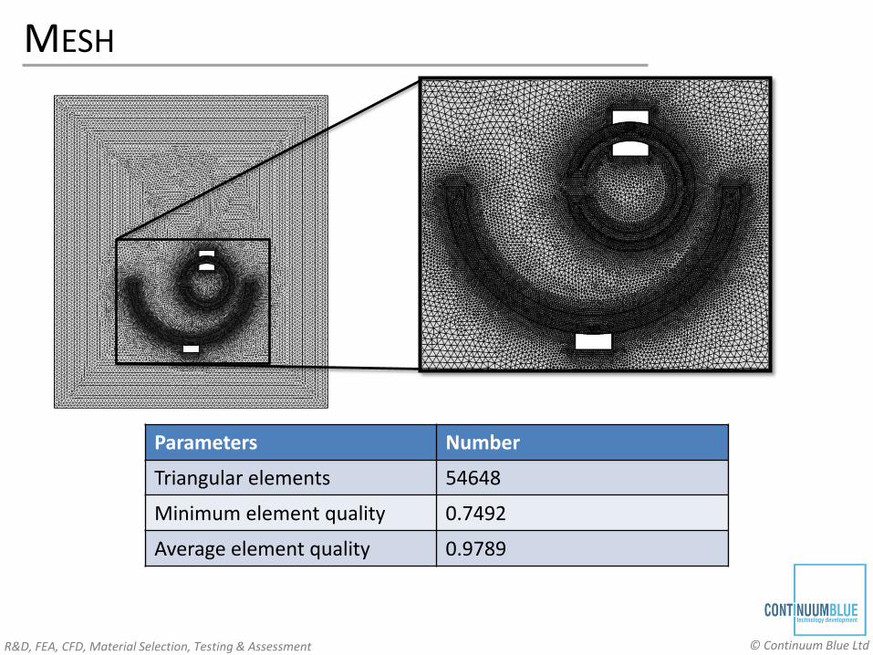
MESH
Parameters Number
Triangular elements 54648
Minimum element quality 0.7492
Average element quality 0.9789
R&D, FEA, CFD, Material Selection, Testing & Assessment © Continuum Blue Ltd
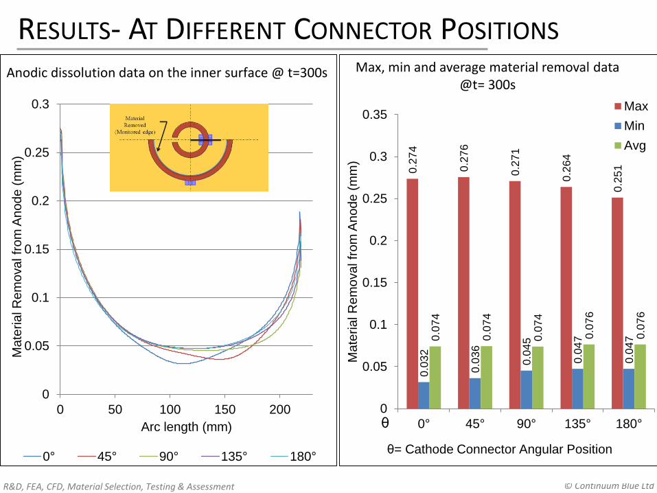
RESULTS- AT DIFFERENT CONNECTOR POSITIONS
0
0.05
0.1
0.15
0.2
0.25
0.3
0 50 100 150 200
Ma
teria
l R
em
ova
l fr
om
An
od
e (
mm
)
Arc length (mm)
0° 45° 90° 135° 180°
Anodic dissolution data on the inner surface @ t=300s
0.2
74
0.2
76
0.2
71
0.2
64
0.2
51
0.0
32
0.0
36
0.0
45
0.0
47
0.0
470
.07
4
0.0
74
0.0
74
0.0
76
0.0
76
0
0.05
0.1
0.15
0.2
0.25
0.3
0.35
0° 45° 90° 135° 180°
Ma
teria
l R
em
ova
l fr
om
An
od
e (
mm
)
Max
Min
Avg
θ
θ= Cathode Connector Angular Position
Max, min and average material removal data @t= 300s
R&D, FEA, CFD, Material Selection, Testing & Assessment © Continuum Blue Ltd
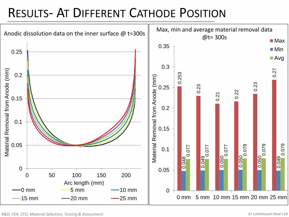
0.2
53
0.2
3
0.2
1
0.2
2 0.2
3
0.2
7
0.0
48
0.0
49
0.0
50
0.0
50
0.0
50
0.0
490
.07
7
0.0
77
0.0
77
0.0
78
0.0
79
0.0
79
0
0.05
0.1
0.15
0.2
0.25
0.3
0.35
0 mm 5 mm 10 mm 15 mm 20 mm 25 mm
Ma
teria
l R
em
ova
l fr
om
An
od
e (
mm
)
Max
Min
Avg
RESULTS- AT DIFFERENT CATHODE POSITIONMax, min and average material removal data
@t= 300s
0
0.05
0.1
0.15
0.2
0.25
0 50 100 150 200
Ma
teria
l R
em
ova
l fr
om
An
od
e (
mm
)
Arc length (mm)
0 mm 5 mm 10 mm
15 mm 20 mm 25 mm
Anodic dissolution data on the inner surface @ t=300s
R&D, FEA, CFD, Material Selection, Testing & Assessment © Continuum Blue Ltd
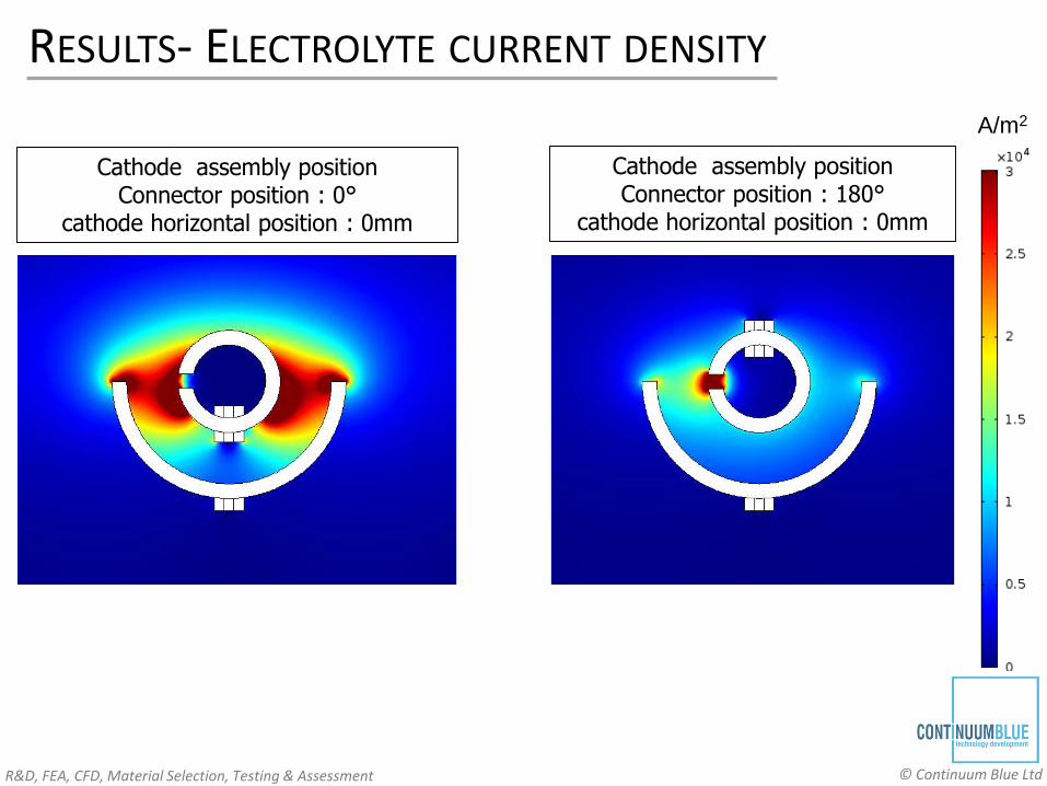
RESULTS- ELECTROLYTE CURRENT DENSITY
A/m2
Cathode assembly position Connector position : 0°
cathode horizontal position : 0mm
Cathode assembly position Connector position : 180°
cathode horizontal position : 0mm
R&D, FEA, CFD, Material Selection, Testing & Assessment © Continuum Blue Ltd
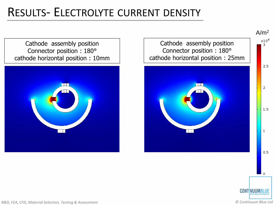
RESULTS- ELECTROLYTE CURRENT DENSITY
A/m2
Cathode assembly position Connector position : 180°
cathode horizontal position : 10mm
Cathode assembly position Connector position : 180°
cathode horizontal position : 25mm
R&D, FEA, CFD, Material Selection, Testing & Assessment © Continuum Blue Ltd
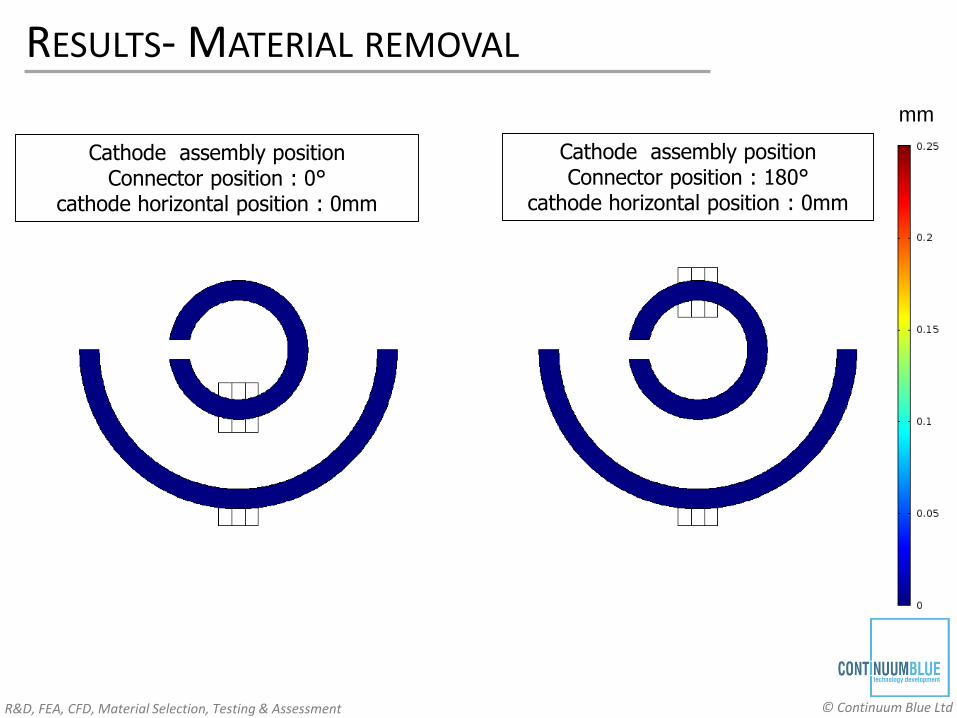
RESULTS- MATERIAL REMOVAL
mm
Cathode assembly position Connector position : 0°
cathode horizontal position : 0mm
Cathode assembly position Connector position : 180°
cathode horizontal position : 0mm
R&D, FEA, CFD, Material Selection, Testing & Assessment © Continuum Blue Ltd
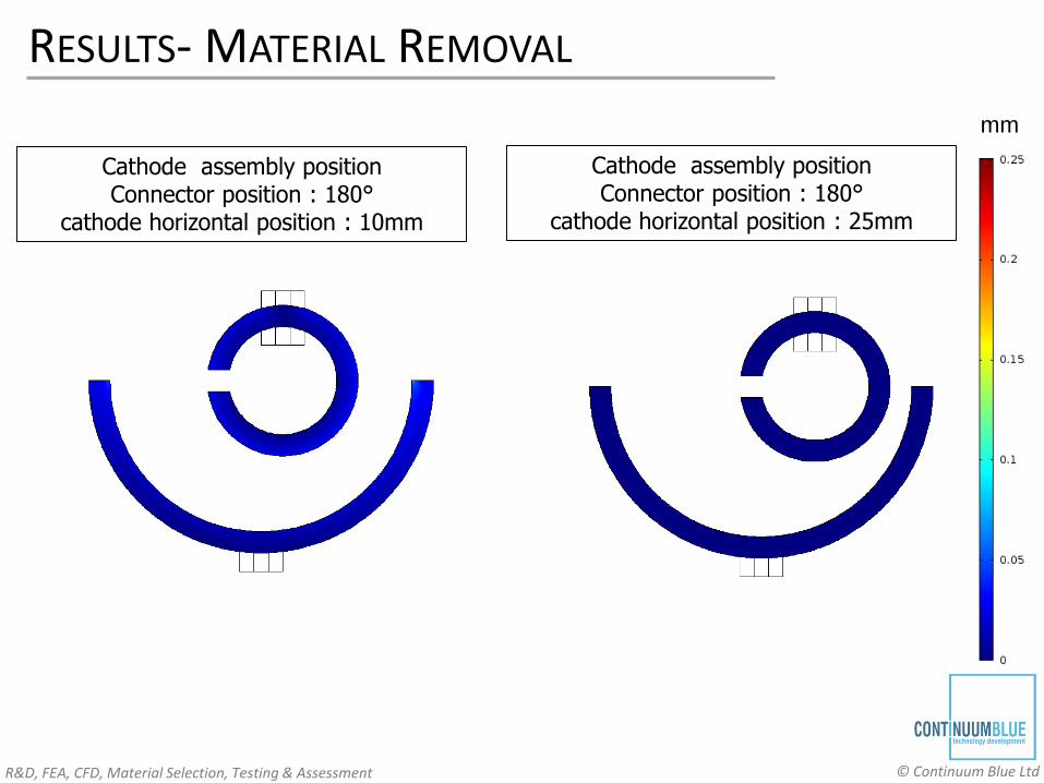
RESULTS- MATERIAL REMOVAL
mm
Cathode assembly position Connector position : 180°
cathode horizontal position : 10mm
Cathode assembly position Connector position : 180°
cathode horizontal position : 25mm
R&D, FEA, CFD, Material Selection, Testing & Assessment © Continuum Blue Ltd
CONCLUSION & DISCUSSION
Conclusion
• In the current paper we discussed about modelling of Electrochemical material removal
process of an super alloy by considering materials major constituents using tertiary current
distribution method in COMSOL
• Conducting such type of simulation can help to understand the effect of change in process
parameters (variables) on the system.
Future Work
• Addition of fluid flow effect (CFD) and mixing of electrolyte of varying concentrations.
• Effect of temperature on the Electrochemical reactions.• Modelling the effect of H2 gas evolution at cathode using bubble flow module.
R&D, FEA, CFD, Material Selection, Testing & Assessment © Continuum Blue Ltd
REFERENCE
1. G.E. Benedict, Nontraditional Manufacturing Processes, Marcel Dekker, 1987
2. R. van Tijum & T. Pajak, The Multiphysics Approach: The Electrochemical Machining
Process, COMSOL Conference Hanover (2008)
3. http://www.rolledalloys.com/alloys/cobalt-alloys /waspaloy/en/
4. COMSOL Multiphysics, Electrodeposition Module Physics Interface Guide Version 4.4,
COMSOL AB (2013)
5. Gleb Mamantov, H.W Jenkins, D.L. Manning, Exchange Current measurements on the
Nickel-Nickel(II) Couple in molten Fluorides
6. www.nptel.ac.in/courses/113108051/module2/lecture9.pdf
7. www.nonmet.mat.ethz.ch/education/courses/ ceramic2 /Exercises2009.pdf
8. http://ocw.mit.edu/courses/chemical-engineering/10-626-electrochemical-energy-
systems-spring-2011/lecture-notes/MIT10_626S11_lec13.pdf

R&D, FEA, CFD, Material Selection, Testing & Assessment © Continuum Blue Ltd
Contact Details
Continuum Blue Ltd.
T: +44 (0) 1443 866 455
W: www.continuum-blue.com
Thank You