research article power management strategy for active...
TRANSCRIPT

Hindawi Publishing CorporationChinese Journal of EngineeringVolume 2013, Article ID 723860, 7 pageshttp://dx.doi.org/10.1155/2013/723860
Research ArticlePower Management Strategy for Active Power Sharing inHydro/PV/Battery Hybrid Energy System
Sweeka Meshram, Ganga Agnihotri, and Sushma Gupta
Department of Electrical Engineering, MANIT, Bhopal, Madhya Pradesh 462051, India
Correspondence should be addressed to Sweeka Meshram; [email protected]
Received 23 September 2013; Accepted 24 October 2013
Academic Editors: K. Ariyur and Y.-C. Song
Copyright © 2013 Sweeka Meshram et al. This is an open access article distributed under the Creative Commons AttributionLicense, which permits unrestricted use, distribution, and reproduction in any medium, provided the original work is properlycited.
Simulation andmodeling of standalone DC linked hydro/PV/battery hybrid energy system (HES) and powermanagement strategy(PMS) for identifying the active power sharing have been done. The performance analysis of the proposed HES and its powermanagement strategy has been done using the simulink toolboxes of MATLAB software. The proposed system consists of 10 kWPV system, 7.5 kW hydro system, battery, and power condition unit. In some remote/rural areas, it is very difficult to satisfy thedemand of electrical power throughout the year with the power grid. In such areas, the power requirement can be fulfilled byrenewable energy system such as hydro or PV system. Either the hydro system or PV system is not capable of supplying powerrequirement throughout the year as both systems are intermittent. Hence, the judicious combination of hydro and PV system hasbeen modeled for electrification. The power management strategy is modeled to manage the power flow of the energy systems andbattery to fulfill the load demand.The presented results clearly show that the proposed HES and its control strategy are suitable forimplementation in remote/rural areas.
1. Introduction
Electrification of remote/isolated areas (where grid acces-sibility is not possible) may be possible by harnessing therenewable energy sources presented in the particular areas.Among these renewable energy sources, hydro and solarenergy sources are more promising for electricity generation.The hydro and PV system are gaining the momentum ofresearchers for electrification in remote/rural areas.
Either standalone hydro system or PV system is notsufficient to fulfill the power requirement throughout theyear. Therefore, for getting the optimal results by combiningthe advantages of hydro and solar energy sources, PV/hydrohybrid system has been analyzed and also installed [1–3].
The geographical and climatic condition affects the per-formance of the hybrid system. Therefore, a backup is neces-sary in the casewhen one of the energy sources is not availableor the power generated by the hybrid system is not capableof fulfilling the power demand. To ensure the continuouspower supply and to take care of intermittent nature of energysystems, diesel generator can be integrated to overcome the
problem [4, 5]. Economic analysis and cost optimizationof such system have been done to ensure the existenceof the system [6, 7]. The additions of diesel generator areadvantageous over the pure renewable energy system butalso have some major problems such as diesel generatorneeds fossil fuel and surplus energy during the good seasoncannot be stored and provides short-term storage [8]. Toovercome these problems, recently, the hydrogen storagesystem is taking the place of diesel generator and such powergenerating systems have been designed and developed forrural and coastal residential applications. It can be concludedthat the hydrogen-based system can become a favorablesystem without aid from the grid system and bring advantagefrom technical and economic point of view and is also suitableto be applied in the rural and coastal residential application[9, 10].
The integration of the diesel generator or hydrogenstorage system adds the cost and complexity of the system.The combination of the hybrid system with battery andefficient power management system (PMS) makes the bestuse of the advantages of each power generating system [11, 12].

2 Chinese Journal of Engineering
Primemover
7.5 kW inductiongenerator
H1
Ica2
Icb2Icc2
Va2 Vb2
Vc2
Hydrosystem
AC-DCconverter
Excitationcapacitor
DC-ACinverter
R, RL,and
motorload
DC bus AC bus
DC-DCconverter
DC-DCconverter
Battery
PV
PV
systemMPPTcontroller
+
panel
Solarirradiance
−
VPVIPV
Figure 1: Schematic diagram of the hybrid energy system.
In this paper, a hydro/PV/battery-based hybrid energysystem (HES) is proposed for electrification of remote/ruralareas. The PV system is capable of generating 10 kW poweronly in sunny days. Therefore, a 7.5 kW hydro system is inte-grated with the PV system to supply the power throughoutthe year. But the PV power is variable and the PV/hydrosystem is also not able to feed the required load demand.Hence, a 200V, 13.5 Ah lead acid battery is also integratedto make the efficient HES system. The power managementsystem (PMS) is developed to control the flow of energy ofindividual power generating system and battery. The PMS isdesigned such that the use of battery is as low as possible.Thehydro/PVhybrid systemworks as a dominant system andbattery as a backup.
2. System Description
Figure 1 shows the schematic diagram of the standalonePV/hydro hybrid energy system. There are three main partsof the HES: hydro system, PV system, and battery. The hydrosystem is configured by hydro turbine driven self-excitedinduction generator (SEIG) with initial excitation require-ment fulfilled by the capacitor bank and anAC/DC converter.The PV system consists of PV array and DC/DC converter.the maximum power point tracking (MPPT) controller isemployed to enhance the system efficiency and to control theDC/DC converter.
In the HES, the renewable hydro and PV system areconsidered as a primary source for supplying load demandand battery is used as a backup and storage system. The HESis developed to be implemented in the remote/isolated areas;hence, if HES generated power is inefficient to sustain theload, then battery power will be delivered to balance thepower demand.
The control of all the renewable systems and battery isprovided through the independent controllers such as MPPTcontroller. To interface hydro/PV system and battery, thevoltage levels must be the same. Hence, DC/DC convertersare used in the HES system to link the common DC voltageof the renewable systems.
3. System Component Modeling
To investigate the performance of the HES system and itsPMS, mathematical models of its main components havebeen developed and simulated using the MATLAB simulinktoolbox. The mathematical models for hydro system, PVsystem, and battery have been developed in this section.
3.1. Hydro System. A 7.5 kW hydro system uses SEIG andcapacitor bank. The model equation of the SEIG can berepresented as
[V] = [𝑅] [𝑖] + [𝐿] 𝑝 [𝑖] + 𝜔𝑔 [𝐺] [𝑖] . (1)
The current derivative (i.e.,𝑝[𝑖] = 𝑑𝑖/𝑑𝑡) can be expressedfrom (1) as
𝑝 [𝑖] = [𝐿]−1{[V] − [𝑅] [𝑖] − 𝜔𝑔 [𝐺] [𝑖]} , (2)
where
[V] = [V𝑑𝑠 V𝑞𝑠 V𝑑𝑟 V𝑞𝑟]𝑇
,
[𝑖] = [𝑖𝑑𝑠 𝑖𝑞𝑠 𝑖𝑑𝑟 𝑖𝑞𝑟]𝑇
,
[𝑅] =[[[
[
𝑅𝑠 0 0 0
0 𝑅𝑠 0 0
0 0 𝑅𝑟 0
0 0 0 𝑅𝑟
]]]
]
,

Chinese Journal of Engineering 3
[𝐿] =[[[
[
𝐿 𝑙𝑠 + 𝐿𝑚 0 𝐿𝑚 0
0 𝐿 𝑙𝑠 + 𝐿𝑚 0 𝐿𝑚𝐿𝑚 0 𝐿 𝑙𝑟 + 𝐿𝑚 0
0 𝐿𝑚 0 𝐿 𝑙𝑟 + 𝐿𝑚
]]]
]
,
[0] =[[[
[
0 0 0 0
0 0 0 0
0 −𝐿𝑚 0 𝐿 𝑙𝑟 + 𝐿𝑚𝐿𝑚 0 𝐿 𝑙𝑟 + 𝐿𝑚 0
]]]
]
.
(3)
V𝑑𝑟 and V𝑞𝑟 will be zero when the rotor terminals of theSEIGs are shorted.
The developed electromagnetic torque (𝑇𝑒) of the SEIG isas follows:
𝑇𝑒 =3𝑃
4𝐿𝑚 (𝑖𝑞𝑠𝑖𝑑𝑟 − 𝑖𝑑𝑠𝑖𝑞𝑟) . (4)
The electromechanical torque of the SEIG is modeled as
𝑇shaft = 𝑇𝑒 + 𝐽 (2
𝑃)𝑑𝜔𝑔
𝑑𝑡. (5)
The derivative of rotor speed (𝑑𝜔𝑔/𝑑𝑡) can be derivedfrom (5) as follows:
𝑑𝜔𝑔
𝑑𝑡=(𝑃/2) (𝑇shaft − 𝑇𝑒)
𝐽. (6)
The torque (𝑇shaft) is transmitted to shaft of SEIG to theprime mover.
The capacitor bank used for initial excitation of the SEIGcan be mathematically modeled as
𝑑𝑉𝑠𝑞
𝑑𝑡=𝑖𝑐𝑞
𝐶𝑞,
𝑑𝑉𝑠𝑑
𝑑𝑡=𝑖𝑐𝑑
𝐶𝑑,
(7)
where 𝐶𝑑 and 𝐶𝑞 are the 𝑑 and 𝑞 axis component of the 3-𝜙capacitor bank connected at the stator terminal of the SEIG.
3.2. PV System Characteristics and Modeling. PV systemconsists of PV array and DC/DC converter. PV array is theseries and parallel combination of many PV cells to get thedesired output voltage and current. The PV array exhibitsthe nonlinear VI characteristic. In this paper, SunPowerTH305 solar panel is used. The panel utilizes the 96 SunPowerall-back contact monocrystalline solar cells. The PV systemis modeled to integrate the hydro system and battery tofulfill the power requirement in the remote/isolated areas.The PV system with nonlinear VI characteristic can bemathematically modeled as
𝑉PV =𝑁𝑆𝐴𝑘𝑇
𝑞ln [
𝐼sc − 𝐼PV + 𝑁𝑃𝑁𝑃𝐼𝐷
] −𝑁𝑆
𝑁𝑃𝑅𝑆𝐼PV, (8)
where𝑉PV is the output voltage of the PV panel in V, 𝐼PV is theoutput current of the PV panel in A, 𝐴 is the ideality factor
(2.46), 𝑘 is Boltzmann’s constant (1.38×10⁻²³ J/K), 𝑞 is chargeof electron (1.602 × 10
−19 C), 𝑇 is PV cell temperature in K,𝑁𝑆 is the number of series connected PV modules,𝑁𝑃 is thenumber of parallel connected PV string, 𝐼sc is short circuitcurrent of PV cell in A, 𝐼𝐷 is reverse saturation current of cell(0.0002A), and 𝑅𝑆 is series resistance of PV cell (0.001Ω).
3.3. Lead Acid Battery. In this section, the mathematicalmodeling of the rechargeable lead acid battery has been done,which is used for simulating the hybrid system. A lead acidbattery is modeled as follows:
𝑉𝐵 = 𝑉OCB − 𝑅𝐵𝐼𝐵. (9)
During discharge mode of battery (𝑖∗ > 0),
𝑉OCB = 𝑉0 − 𝑘𝑄
𝑄 − 𝑖𝑡⋅ 𝑖∗− 𝑘
𝑄
𝑄 − 𝑖𝑡𝑖𝑡 + 𝐿−1{exp (𝑠)sel (𝑠)
⋅ 0} .
(10)
During charge mode of the battery (𝑖∗ < 0),
𝑉OCB = 𝑉0 − 𝑘𝑄
𝑖𝑡 + 0.1𝑄⋅ 𝑖∗− 𝑘
𝑄
𝑄 − 𝑖𝑡𝑖𝑡
+ 𝐿−1{exp (𝑠)sel (𝑠)
⋅1
𝑠} ,
(11)
where 𝑉𝐵 is the battery voltage in V, 𝑉OCB is the open circuitvoltage in V, 𝑅𝐵 is the internal resistance of the battery in Ω,𝐼𝐵 is the battery current in A,𝑉0 is the constant voltage of thebattery in V, 𝑘 is the polarization constant in Ah−1, 𝑄 is themaximum battery capacity in Ah, 𝑖𝑡 is the extracted capacityin Ah, 𝑖∗ is the low frequency dynamics in A, exp(𝑠) is theexponential zone dynamics in V, and sel(𝑠) is for representingthe battery mode. For sel(𝑠) = 0, battery will be in dischargemode, and for sel(𝑠) = 1, battery will be in charge mode.
3.4. Power Conditioning Unit
3.4.1. DC-DC Converter. The PV system uses the DC-DCconverter to employ theMPPT to get themaximumefficiencyfrom the PV system with the variation in the temperatureand solar irradiance. The output of the PV array is very less,therefore it is required to boost their voltage. This feature isalso provided by the DC-DC boost converter. Equation (12)describes the output voltage as a function of PV voltage andduty cycle as follows:
𝑉DC =1
1 − 𝐷𝑉PV. (12)
The duty cycle𝐷 is controlled by the MPPT controller.
3.4.2. DC-AC Inverter. The DC-AC inverter accepts theregulated voltage from the DC bus and converts it into an ACvoltage. The inverter AC voltage (𝑉inv) and power (𝑃inv) canbe given as
𝑉inv = 𝑀 ⋅ 𝑉DC∠𝛿 0 < 𝑀 < 1
𝑃inv =𝑀 ⋅ 𝑉DC ⋅ 𝑉𝐿
𝑋sin (𝛿) .
(13)
4 Chinese Journal of Engineering
Calculate PV power at MPP ( ),hydro power ( ), load demand ( ),
and SOC of battery
Calculate power of HES= +
>
Yes
Yes
YesYes
Yes
No
No
No
No
No
Only HES meetsthe required energy
demand=
Battery status ischarged?
Excess power of HEScharges the battery
= PB +
HES and battery sharethe energy demand
Only battery meets therequired energy demand
PB = PL≈ PB ≈ 1/2
Ph
Ph
PL
PL
PL
PL
PH
PH
PH
PH
PH
SOC ≤ 40%
40% ≤ SOC ≤ 80% SOC ≥ 80%
PL
PPV
PPV
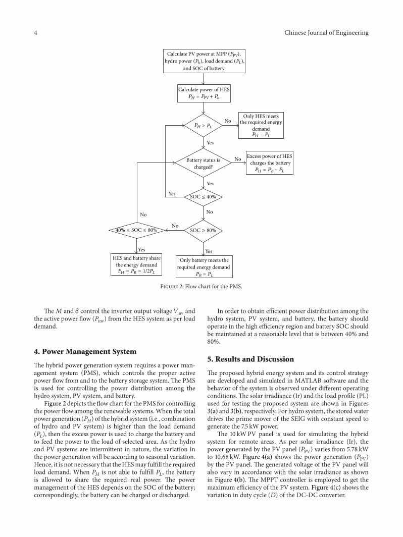
Figure 2: Flow chart for the PMS.
The𝑀 and 𝛿 control the inverter output voltage 𝑉inv andthe active power flow (𝑃inv) from the HES system as per loaddemand.
4. Power Management System
The hybrid power generation system requires a power man-agement system (PMS), which controls the proper activepower flow from and to the battery storage system. The PMSis used for controlling the power distribution among thehydro system, PV system, and battery.
Figure 2 depicts the flow chart for the PMS for controllingthe power flow among the renewable systems.When the totalpower generation (𝑃𝐻) of the hybrid system (i.e., combinationof hydro and PV system) is higher than the load demand(𝑃𝐿), then the excess power is used to charge the battery andto feed the power to the load of selected area. As the hydroand PV systems are intermittent in nature, the variation inthe power generation will be according to seasonal variation.Hence, it is not necessary that theHESmay fulfill the requiredload demand. When 𝑃𝐻 is not able to fulfill 𝑃𝐿, the batteryis allowed to share the required real power. The powermanagement of the HES depends on the SOC of the battery;correspondingly, the battery can be charged or discharged.
In order to obtain efficient power distribution among thehydro system, PV system, and battery, the battery shouldoperate in the high efficiency region and battery SOC shouldbe maintained at a reasonable level that is between 40% and80%.
5. Results and Discussion
The proposed hybrid energy system and its control strategyare developed and simulated in MATLAB software and thebehavior of the system is observed under different operatingconditions.The solar irradiance (Ir) and the load profile (PL)used for testing the proposed system are shown in Figures3(a) and 3(b), respectively. For hydro system, the stored waterdrives the prime mover of the SEIG with constant speed togenerate the 7.5 kW power.
The 10 kWPV panel is used for simulating the hybridsystem for remote areas. As per solar irradiance (Ir), thepower generated by the PV panel (𝑃PV) varies from 5.78 kWto 10.68 kW. Figure 4(a) shows the power generation (𝑃PV)by the PV panel. The generated voltage of the PV panel willalso vary in accordance with the solar irradiance as shownin Figure 4(b). The MPPT controller is employed to get themaximum efficiency of the PV system. Figure 4(c) shows thevariation in duty cycle (𝐷) of the DC-DC converter.

Chinese Journal of Engineering 5
600
700
800
900
1000
0 0.5 1 1.5 2 2.5 3
Time (s)
Ir(W
/m2)
(a)
0 0.5 1 1.5 2 2.5 3
Time (s)
10
15
20
PL
(kW
)
(b)
Figure 3: (a) Solar irradiance inW/m2; (b) required power demandin kW.
Figure 5 shows the combined power generation of thehydro and PV system (𝑃𝐻). The PMS controls the charg-ing/discharging of the battery bank. When the 𝑃𝐻 is less thanthe𝑃𝐿, the parallel connected hydro and PV systemwill fulfillthe load demand, and when the 𝑃𝐻 is greater than the 𝑃𝐿,battery will also share the power.
Before 0.5 sec, the 𝑃𝐻 is capable of fulfilling the requiredload demand. Hence, the battery will charge only. Duringperiod 0.5–0.75 seconds, the load demand is 20 kW and the𝑃𝐻 is 16.54 kW. In that duration, the battery is sharing thepower to compensate the anticipated load and dischargesthe stored power. During 0.75–0.1 seconds, again the loaddemand 𝑃𝐿 is greater than the 𝑃𝐻, therefore, the battery is indischargemode. Figures 6(a) and 6(b) show the power sharedby the battery and current through the battery, respectively.Figure 6(c) shows the % SOC of the battery and shows thebattery charging and discharging.
Figures 7(a) and 7(b) show the waveform of load currentfor the resistive load of about 5 kW and RL load of about2.5 kW with 0.8 lagging power factor. For clear vision, onephase with the time range from 0.8 sec to 1.2 sec is shown.Figures 7(c) and 7(d) show the stator current and speed of3.7 kW, 415V, 1500 rpm, and 50Hz IM load, respectively.
6. Conclusion
In remote/isolated areas, where grid accessibility is notpossible, the electrical power requirement can be fulfilledby harnessing the renewable energy sources. For such areas,standalone hydro/PV/battery hybrid system has been mod-eled and simulated using the MATLAB simulink toolboxes.To improve the power quality of the hybrid system and to
0 0.5 1 1.5 2 2.5 3
Time (s)
6
8
10
PPV
(kW
)
(a)
0 0.5 1 1.5 2 2.5 3
Time (s)
200
250
300
VPV
(kW
)(b)
0.55
0.5
0.45
0.40 0.5 1 1.5 2 2.5 3
Time (s)
D
(c)
Figure 4: (a) Output power of PV panel with respect to solarirradiance. (b) PV panel output voltage. (c) Duty cycle of the DC-DC converter to get MPP.
5
10
15
20
0 0.5 1 1.5 2 2.5 3
Time (s)
PH
(kW
)
Figure 5: Total power generation of hydro and PV system.
control the power distribution among the power generatingsystems, an energy management system has been developed.The proposed system is tested under the resistive, RL, andinduction motor (IM) load. The demonstrated results showthat the proposed system can fulfill the power requirement ofremote areas and the control strategy can supervise efficientlyand maintain the battery SOC within the specified region.

6 Chinese Journal of Engineering
0 0.5 1 1.5 2 2.5 30
1
2
3
4
Time (s)
PB
(kW
)
(a)
0
5
10
−5
−10
0 0.5 1 1.5 2 2.5 3
Time (s)
I B(A
)
(b)
40
45
50
SOC
0 0.5 1 1.5 2 2.5 3
Time (s)
(c)
Figure 6: (a) Power met by the battery bank. (b) Current of the battery during charging/discharging. (c) Battery % SOC.
0.8 0.85 0.9 0.95 1 1.05 1.1 1.15 1.2
10
0
−10
Time (s)
I LR
(a)
0.8 0.85 0.9 0.95 1 1.05 1.1 1.15 1.2
Time (s)
5
−5
0
I LRL
(b)
0.2 0.4 0.6 0.8 1 1.2
10
0
0−10
Time (s)
I sIM
(c)
N
0 0.1 0.2 0.3 0.4 0.5 0.6 0.7 0.8 0.9 1
Time (s)
0
500
1000
1500
(d)
Figure 7: (a) Current through the linear R load. (b) Current through the linear RL load. (c) Current through the IM load. (d) Speed of theIM.
Appendix
(a) The parameters of 7.5 kW, 415V, 50Hz, Δ-connected,4-pole induction machine:
𝑅𝑠 = 1Ω, 𝑅𝑟 = 0.77Ω,𝑋𝑙𝑟 = 𝑋𝑙𝑠 = 1.5Ω, 𝐽 = 0.1384 kg-m2,𝐿𝑚 = 0.134H (Im < 3.16),𝐿𝑚 = 9𝑒− 5𝐼
2
𝑚−0.0087𝐼𝑚 −0.1643 (3.16 < 𝐼𝑚 <
12.72),𝐿𝑚 = 0.068H (𝐼𝑚 > 12.72).
(b) Prime mover characteristics:
𝑇sh = 𝐾1 − 𝐾2𝜔𝑟,𝐾1 = 1570, 𝐾2 = 10.
(c) PV panel parameters:
module type: sunPower SPR-305-WHT,no. of cells/module = 96,no. of series connected modules/string = 5,no. of parallel strings = 7,

Chinese Journal of Engineering 7
module specification under STC:𝑉oc = 64.2, 𝐼sc = 5.96, 𝑉mp = 54.7, and𝐼mp = 5.58,
model parameters for one module:𝑅𝑠 = 0.038, 𝑅𝑝 = 993.5, 𝐼sat = 3.1949𝑒 − 8,𝐼ph = 5.9602, 𝐴 = 1.3, and 𝐼𝐷 = 0.0002.
(d) Battery parameters:
type of battery = lead acid,no. of battery connected in series = 3,nominal voltage = 200V,maximum capacity of battery = 6.5 Ah,internal resistance = 0.382Ω.
(e) Boost converter parameters:
𝐶𝐵 = 15 𝜇F, 𝐿𝐵 = 170mH,switching freq. = 10 kHz.
References
[1] R. Muhida, A. Mostavan, W. Sujatmiko, M. Park, and K.Matsuura, “10 Years operation of a PV-micro-hydro hybridsystem in Taratak, Indonesia,” Solar Energy Materials and SolarCells, vol. 67, no. 1–4, pp. 621–627, 2001.
[2] E. M. Nfah and J. M. Ngundam, “Feasibility of pico-hydroand photovoltaic hybrid power systems for remote villages inCameroon,” Renewable Energy, vol. 34, no. 6, pp. 1445–1450,2009.
[3] J. Kenfack, F. P. Neirac, T. T. Tatietse, D. Mayer, M. Fogue,and A. Lejeune, “Microhydro-PV-hybrid system: sizing a smallhydro-PV-hybrid system for rural electrification in developingcountries,” Renewable Energy, vol. 34, no. 10, pp. 2259–2263,2009.
[4] D. Saheb-Koussa, M. Haddadi, and M. Belhamel, “Economicand technical study of a hybrid system (wind-photovoltaic-diesel) for rural electrification in Algeria,” Applied Energy, vol.86, no. 7-8, pp. 1024–1030, 2009.
[5] J. L. Bernal-Agustın and R. Dufo-Lopez, “Simulation andoptimization of stand-alone hybrid renewable energy systems,”Renewable and Sustainable Energy Reviews, vol. 13, no. 8, pp.2111–2118, 2009.
[6] R. Dufo-Lopez, J. L. Bernal-Agustın, J. M. Yusta-Loyo et al.,“Multi-objective optimization minimizing cost and life cycleemissions of stand-alone PV-wind-diesel systems with batteriesstorage,” Applied Energy, vol. 88, no. 11, pp. 4033–4041, 2011.
[7] M. S. Ngan andC.W. Tan, “Assessment of economic viability forPV/wind/diesel hybrid energy system in southern PeninsularMalaysia,” Renewable and Sustainable Energy Reviews, vol. 16,no. 1, pp. 634–647, 2012.
[8] P. C. Ghosh, B. Emonts, and D. Stolten, “Comparison ofhydrogen storage with diesel-generator system in a PV-WEChybrid system,” Solar Energy, vol. 75, no. 3, pp. 187–198, 2003.
[9] M. Z. Ibrahim, R. Zailan, M. Ismail, and A. M. Muzathik, “Pre-feasibility study of hybrid hydrogen based energy systems forcoastal residential applications,” Energy Research Journal, vol. 1,pp. 12–21, 2010.
[10] B. Panahandeh, J. Bard, A. Outzourhit, andD. Zejli, “Simulationof PV-wind-hybrid systems combined with hydrogen storagefor rural electrification,” International Journal of HydrogenEnergy, vol. 36, no. 6, pp. 4185–4197, 2011.
[11] K.-S. Jeong, W.-Y. Lee, and C.-S. Kim, “Energy managementstrategies of a fuel cell/battery hybrid system using fuzzy logics,”Journal of Power Sources, vol. 145, no. 2, pp. 319–326, 2005.
[12] C. Wang and M. H. Nehrir, “Power management of a stand-alone wind/photovoltaic/fuel cell energy system,” IEEE Trans-actions on Energy Conversion, vol. 23, no. 3, pp. 957–967, 2008.

International Journal of
AerospaceEngineeringHindawi Publishing Corporationhttp://www.hindawi.com Volume 2014
RoboticsJournal of
Hindawi Publishing Corporationhttp://www.hindawi.com Volume 2014
Hindawi Publishing Corporationhttp://www.hindawi.com Volume 2014
Active and Passive Electronic Components
Control Scienceand Engineering
Journal of
Hindawi Publishing Corporationhttp://www.hindawi.com Volume 2014
International Journal of
RotatingMachinery
Hindawi Publishing Corporationhttp://www.hindawi.com Volume 2014
Hindawi Publishing Corporation http://www.hindawi.com
Journal ofEngineeringVolume 2014
Submit your manuscripts athttp://www.hindawi.com
VLSI Design
Hindawi Publishing Corporationhttp://www.hindawi.com Volume 2014
Hindawi Publishing Corporationhttp://www.hindawi.com Volume 2014
Shock and Vibration
Hindawi Publishing Corporationhttp://www.hindawi.com Volume 2014
Civil EngineeringAdvances in
Acoustics and VibrationAdvances in
Hindawi Publishing Corporationhttp://www.hindawi.com Volume 2014
Hindawi Publishing Corporationhttp://www.hindawi.com Volume 2014
Electrical and Computer Engineering
Journal of
Advances inOptoElectronics
Hindawi Publishing Corporation http://www.hindawi.com
Volume 2014
The Scientific World JournalHindawi Publishing Corporation http://www.hindawi.com Volume 2014
SensorsJournal of
Hindawi Publishing Corporationhttp://www.hindawi.com Volume 2014
Modelling & Simulation in EngineeringHindawi Publishing Corporation http://www.hindawi.com Volume 2014
Hindawi Publishing Corporationhttp://www.hindawi.com Volume 2014
Chemical EngineeringInternational Journal of Antennas and
Propagation
International Journal of
Hindawi Publishing Corporationhttp://www.hindawi.com Volume 2014
Hindawi Publishing Corporationhttp://www.hindawi.com Volume 2014
Navigation and Observation
International Journal of
Hindawi Publishing Corporationhttp://www.hindawi.com Volume 2014
DistributedSensor Networks
International Journal of