research article optimum feed ratio analysis for tri … · optimum feed ratio analysis for...
TRANSCRIPT
Research Article
*Correspondence : [email protected]
Optimum Feed Ratio Analysis
for Tri-Reforming of Methane Using
Thermodynamic Equilibrium Method
Sompop Jarungthammachote* Department of Mechanical Engineering, Faculty of Engineering,
Kasetsart University, Si Racha District, Chon Buri 20230, Thailand
Abstract
Tri-reforming of methane was studied in this work through a method called Gibbs free
energy minimization or thermodynamic equilibrium. Optimum feed ratios of H2O/CH4 and
CO2/CH4 at a specific O2/CH4 ratio were investigated based on optimum conditions which are
CH4 and CO2 conversions are equal to or higher than 90%, H2/CO ratio is 2.0 and H2 yield
should be as high as possible. Carbon formation during reaction was also focused for each
case of the optimum feed ratio. Moreover, heat required to raise the reaction temperature was
calculated and presented in terms of CO2 equivalent. Net CO2 emission from the process was
finally expressed. The results showed that the values of optimum H2O/CH4 and CO2/CH4
ratios reduce as O2/CH4 ratio increases. The values of carbon selectivity, reflecting solid
carbon formation, are very low. The net CO2 emission is in the range of 0.176-0.137 kmol per
1 kmol of CH4
Keywords: Tri-reforming; CO2 emission; Hydrogen production; Thermodynamic
equilibrium
1. Introduction Reforming of natural gas is the well-
known method for syngas production. Steam
reforming of natural gas is the most widely
used method for hydrogen production in
industrial scale [1]. Steam reforming of
methane, shown in reaction (1), provides
high H2/CO ratio
4 2 2
o
298
3
ΔH =206MJ/kmol
CH H O CO H (1)
CO2 reforming, also called dry
reforming, is of interest to many researchers.
It utilizes CO2, a major green-house gas, to
react with methane and produces syngas with
H2/CO ratio of 1.0, as presented in reaction
(2).
4 2 2
o
298
2 2
ΔH =247.3MJ/kmol
CH CO H CO (2)
The partial oxidation of methane can be
explained as a sub-stoichiometric combustion
of methane and it is an exothermic reaction
which can be described as:
4 2 2
o
298
12
2
ΔH =-36MJ/kmol
CH O CO H (3)
A new process, called tri-reforming,
has been focused upon by researchers. It is
the combination of three previous methods
[2]. The idea of tri-reforming process shown
in Ref. [2] is that the flue gas, which consists

Vol.20, No.4, October-December 2015 Thammasat International Journal of Science and Technology
69
of CO2, H2O, and O2, reacts with methane in
a main reactor under controlled temperature
condition. The desirable product is syngas or
the mixture of H2 and CO. Tri-reforming can
produce syngas with H2/CO ratio suitable for
the production of methanol, dimethyl ether,
and other liquid hydrocarbon [3]. One of the
most important concepts of this process is
that the reforming reactions (reactions (1)
and (2)) are endothermic. However, the
oxidation reaction (reaction (3)) is
exothermic. The combination of these
reactions contributes to energy saving
because heat generated from reaction (3)
compensates for the energy demand of the
reforming reactions. Moreover, the tri-
reforming process uses CO2 as co-reactant.
It, therefore, reduces CO2 emission from
industries and power plants. Song and Pan
[2] have proposed and experimentally
exhibited a tri-reforming process utilizing the
power station flue gas for syngas production.
The authors have also pointed out the
advantage of the process is that O2 and H2O
in co-reactant can reduce carbon deposition
onto catalyst. Halmann and Steinfeld [4, 5]
have done an analysis for tri-reforming of
fossil fuel-fired flue gases. The resulting
syngas was used for methanol, ammonia or
hydrogen production. Fuel saving and CO2
emission avoidance were observed. A
chemical simulation program was performed
by Zhang et al. [3] to simulate methanol
production coupled to a tri-reforming
process. The optimum CH4/flue gas ratio was
focused. The optimization of heat integration
was also carried out to minimize both utility
and capital costs. The influence of the
feedstock composition on methane
conversion, the H2/CO molar ratio of the
syngas obtained by tri-reforming of methane
over Ni/β-SiC based catalyst have been
described by García-Vargas et al. [6]. H2/CO
ratio ranging from 1.9-2.1 was focused. The
study was observed that the effect of both
water and oxygen volume flow on the H2/CO
ratio was positive while that of methane and
carbon dioxide volume flow was negative.
Thermodynamic and economic studies for
combined CO2 and steam reforming and tri-
reforming for syngas production have been
presented by et al. [7]. The result
showed that combined reforming and tri-
reforming of CH4 are competitive processes,
with lower operating and capital costs in
comparison with steam reforming.
A novel multi-tubular fixed bed tri-
reformer assisted with hydrogen and oxygen
perm-selective membranes was proposed by
Rahimpour et al. [8]. A kinetic model was
developed to study this novel reactor. This
model requires information of chemical
reactions taking place as well as flow
phenomena in the reactor. Recently, the
kinetic model was used to study the tri-
reforming process coupled with steam
reforming reaction in a double concentric
tube multi-tubular reactor [9] and to study
the thermally coupled reactor (styrene
reaction and tri-reforming) [10].
From the literature review, tri-
reforming has been studied through kinetic
models. However, the disadvantages of this
method are: 1.) it requires the information of
the major chemical reactions and 2.) the
complex numerical method must be applied
to find the solution. To operate a tri-
reforming process efficiently in terms of high
CH4 and CO2 conversions as well as high H2
yield, a suitable combination of co-reactant,
CO2, H2O, and O2 is desirable to know.
Moreover, the suitable mixture of reactants
must also lead to an appropriate H2/CO ratio.
Due to the complexity of the chemical
reactions taking place in this process, a
simulation method, called thermodynamic
equilibrium based on Gibbs free energy
minimization, is proposed to use, because it
does not need the information about chemical
reactions practically occurring in the process
[11].
In this work, thermodynamic analysis of tri-
reforming process is performed through
Gibbs free energy minimization method or
non-stoichiometric equilibrium method. The
optimum feed ratios of CO2/CH4, H2O/CH4,

Thammasat International Journal of Science and Technology Vol.20, No.4, October-December 2015
70
and O2/CH4 are investigated. The energy
required for each optimum case is found and
net CO2 emission is finally expressed.
2. Model Description 2.1 Non-stoichiometric
Equilibrium Model The thermodynamic equilibrium
model can be developed using two
approaches. The first one is an equilibrium
model based on equilibrium constants known
as the stoichiometric model. This method
requires the information of chemical
reactions occurring in the considered system.
Therefore, it is not suitable for a chemical
system in which many chemical reactions
take place. The second method is a non-
stoichiometric equilibrium calculation based
on Gibbs free energy minimization. The
concept of this method is that, at equilibrium
state, total Gibbs free energy of system is
minimum. The total Gibbs free energy of a
system is defined as:
1
Nt
i i
i
G n
(4)
where in is the number of moles of species i
( 1,2,...,i N ) and i is the chemical
potential of species i and it can be calculated
as follows [11]:
lno ii i o
i
fG RT
f
(5)
where R and T are the universal gas
constant (8.3145 kJ/kmol·K) and temperature
in Kelvin, respectively. if represents the
fugacity of species i . o
iG and o
if are the
standard Gibbs free energy and the standard
fugacity of species i , respectively. For
reaction in gas phase, the fugacity can be
calculated by:
ii io
i o
f Py
f P (6)
where i is the fugacity coefficient of
component i . Substituting Eqs. (5) and (6)
into Eq. (4), gives the following result.
1 1
lnN N
t o i ii i i
i i o
y PG n G n RT
P
(7)
If solid carbon is involved in the system, Eq.
(7) can be rewritten as [12]:
1 1
( ) ( )
1 1
lnN N
t o oi ii i i C s C s
i i o
y PG n G n RT n G
P
(8)
The standard Gibbs free energy of chemical
species i can be computed from the
following equation.
o o o
i i iG H T S (9)
The values of standard enthalpy, o
iH , and
standard entropy, o
iS , are described in terms
of polynomial equations. Data from the
NASA technical memorandum 4513 [13] are
used to calculate both thermodynamic
properties. For the fugacity coefficient
calculation, Peng-Robinson equation of state
with v n d r W ls’ mixing rul s was used,
as described in [14].
,
ln 1 ln
1 2ln
8 1 2
2
ii
k k i
k i
BZ Z B
B
Z BA
B Z B
x AB
A B
(10)
2 2
, ,
, ,
,i k i k i k i k
i k i k
aP bPA B
R T RT
a x x a b x x b
(11)

Vol.20, No.4, October-December 2015 Thammasat International Journal of Science and Technology
71
O’ onn ll nd H il [15] discussed that
calculation of ,i ka can be conducted by
,i k i ka a a while b can be alternatively
estimated by i i
i
b x b . These calculations
are applied in this study for a and b . Now,
the problem is to find the values of in which
minimize the objective function tG . The
appropriate method, which has been usually
performed for minimization of Gibbs free
energy problem, is Lagrange multiplier [11].
The constraint of this problem is that the
number of moles of each element in the
system remains unchanged [12]:
,
N
i i j j
i
n ( 1,2,...,j E ) (12)
where ,i j is the number of atoms of the j
element presenting in each molecule of
species i and j is total number of atoms of
j element in the system. The Lagrangian
function ( L ) is formed by multiplying the
Lagrange multipliers of element j (j ) to
constraints and subtracting these terms fromtG .
,
1 1
E Nt
j i j i j
j i
L G n
(13)
The minimum of this function is obtained by
taking the partial derivative of Eq. (13) with
respect to in and setting these equations
equal to zero. In this step, N equations are
formed and Eq. (12) provides E equations.
These N E equations permit determination
of N E unknowns (1,...,i Nn n n and
1,...,j E ). In this study, only 6 gas
species are assumed to be found in the
reactor. However, for some cases solid
carbon is also considered. A computer code
modified from previous work [11] is used to
find the equilibrium compositions.
2.2 Energy Balance
The reactions occurring in the tri-
reformer have both endothermic and
exothermic reactions. The endothermic
reactions consume heat generated from
exothermic reactions. In some cases, energy
supplied from external source for heating the
mixture to reach the desired reaction
temperature is required. To obtain the value
of additional energy needed, the first law of
thermodynamics or energy balance is applied
to the process by:
( , )
( , )
req R R R
R react
P P P
P prod
Q H T P
H T P
(14)
where reqQ is the energy in form of heat
required to raise the reaction temperature. No
heat transfer to the environment is assumed
in this calculation. RH and
PH are
enthalpies of reactant and product mixtures at
specific states, respectively. Both molar
specific enthalpies can be calculated by:
D igh h h (15)
where igh and Dh are molar specific
enthalpy of ideal gas and molar specific
enthalpy departure, respectively. The
enthalpy departure is given by the following
equation [14]:
( 1)8
(1 2)ln
(1 2)
D
daT a
dTh RT Zb
Z B
Z B
(16)
In the calculation of heat required, the
enthalpies of reactant and product can be
computed in kJ/kmol and they are converted
to kJ/kg. Due to mass conservation
principles, mass of reactant is equal to mass
of product. The units of both enthalpies are

Thammasat International Journal of Science and Technology Vol.20, No.4, October-December 2015
72
the same; therefore, the amount of heat can
be estimated in kJ/kg and total heat required
can be finally found in kJ or MJ. The
calculation procedure described in this
section is illustrated in Figure 1.
Fig.1. The calculation procedure.
3. Validation of Model The thermodynamic equilibrium
model developed in this study was validated
by comparing the calculation results with that
from other works. In the validation, the mole
fractions of gas species in product gas were
compared. For some cases, solid carbon was
also focused. Six calculation cases obtained
from H lm nn nd S inf ld’s works [4, 5]
were used to compare with the results from
the present model. All validation results
show the agreement between calculation
results from the model in this study and that
from H lm nn nd S inf ld’s works wi h
the maximum relative error less than 0.5%.
Figure 2 illustrates an example of a
validation case.
Fig.2. Comparison of equilibrium
compositions in tri-reforming between (a)
H lm nn nd S inf ld’s work, [4] and (b)
present study, at given fixed feed ratio
CH4:CO2:H2O:O2:N2= 60:9:49:2.5:69.5, at 1
atm.
4. Results and Discussion According to the information given
by Zhang et al. [3] it can be found that
hydrogen production and CH4 conversion are
suppressed as the pressure increases.
Moreover, Zhang et al. [3] also pointed out
that CO and H2 productions reach maximum
at a temperature of 850oC. Therefore, they
recommended that the optimum reaction
temperature and pressure are T=850oC and
P=1 atm, respectively, and these conditions
are also employed in this study.
For the feed compositions, Song and
Pan, [2] informed that, for syngas production
with H2/CO =2.0, the best feed compositions
should be CH4:CO2:H2O:O2 = 1:0.3-0.4:0.6-
0.8:0.1-0.2. In this study, O2/CH4 ratio in
range of 0.1-0.2 is considered. At a specific
O2/CH4 ratio, feed ratios of CO2/CH4 and

Vol.20, No.4, October-December 2015 Thammasat International Journal of Science and Technology
73
H2O/CH4 are varied to investigate the
optimum point. The optimal conditions are
CH4 conversion 90% , CO2 conversion
90% , H2/CO = 2.0, and maximum H2
yield. CH4 and CO2 conversions as well as
H2 yield are defined as the following:
4
4,in 4,out
4,in
CH conversion (%)
CH CH100%
CH
(17)
2
2,in 2,out
2,in
CO conversion (%)
CO CO100%
CO
(18)
2
2,out
4,in 2 in
H yield(%)=
H×100%
2CH +H O
(19)
4.1 Effects of CO2/CH4 and
H2O/CH4 Ratios
To study the effects of different
combinations of CO2/CH4 and H2O/CH4
ratios on syngas production, O2/CH4 ratio is
initially fixed at 0.1. The reaction
temperature and pressure are set at 850oC and
1 atm, respectively. The equilibrium
calculation was done at different CO2/CH4
and H2O/CH4 ratios and the results are shown
in Figure 3.
From Figure 3 (a), it is clearly
observed that CH4 conversion is higher than
90% in these ranges of CO2/CH4 and
H2O/CH4 ratios. CH4 conversion increases
with increasing CO2 or H2O, because
increases of oxidants can react with more
CH4. This phenomenon is also found in Ref.
[16].

Thammasat International Journal of Science and Technology Vol.20, No.4, October-December 2015
74
Fig.3. Effects of CO2/CH4 and H2O/CH4 on
(a) CH4 conversion, (b) CO2 conversion, (c)
H2 yield, (d) H2/CO ratio.
Figure 3 (b) illustrates CO2 conversion. A
horizontal plane indicates 90% CO2
conversion level. In the figure, CO2
conversion higher than 90% can be observed
at low CO2/CH4 and H2O/CH4 ratios.
Increase of H2O content causes a significant
decrease of CO2 conversion, because H2O is
more chemical reactive than CO2. Therefore,
CH4 reacts with H2O rather than CO2.
Negative CO2 conversion is found in this
figure, especially at low CO2/CH4 and high
H2O/CH4 ratios. From the definition of CO2
conversion, it implies that CO2 produced in
the process is more than that added to the
reformer. The negative conversion is also
found in Ref. [16]. However, CO2 conversion
becomes positive when H2O/CH4 ratio is less
than 0.9.
The equilibrium calculation of H2
yield is shown in Figure 3 (c). H2 production
reaches maximum at low CO2/CH4 and
H2O/CH4 ratios. Beyond the maximum H2
yield location, reducing CO2/CH4 or
H2O/CH4 ratio causes insignificant reduction
of H2 yield. Increases in H2O and CO2
contents induce decreasing H2 yield. Adding
more H2O with fixed CH4, O2, and CO2 can
enhance H2 production. However, from
investigation of H2O production, increase of
H2O in feed composition also causes more
generation of H2O in product gas. Additional
H2O increases the value of the denominator
in Eq. (19) and consequently decreases H2
yield. Increasing CO2 content reduces H2
production. The possible reason is the effect
of reverse water gas shift reaction, which has
become predominant [17].
For H2/CO ratio, it is one of the most
important parameters for the tri-reforming
process. H2/CO ratio was set to be equal to
2.0, which is suitable for methanol
production. From Figure 3 (d), the plane
indicated by H2/CO=2.0 intersects with
H2/CO surface at low CO2/CH4 ratio.
Moreover, it also shows that an H2/CO ratio
of 2.0 can be achieved in this range of
H2O/CH4 and CO2/CH4 ratios in the feed gas.
4.2 Optimum CO2/CH4 and
H2O/CH4 Ratios
As mentioned in the beginning of
this section, the values of CO2/CH4 and
H2O/CH4 ratios, obtaining optimal
conditions, need to be found. In the first case,
the optimum feed ratios of CO2/CH4 and
H2O/CH4 for O2/CH4 = 0.1 are investigated.
O2 content, then, increases and new optimum
feed ratios of CO2/CH4 and H2O/CH4 are
observed.
Figure 4 depicts the optimum
CO2/CH4 and H2O/CH4 ratios, based on the
optimum conditions mentioned above, for
different O2/CH4 ratios. In the figure, the
dash line presents the CO2 conversion
profile, while the solid line illustrates the
H2/CO ratio. According to the optimum
conditions, the optimum CO2/CH4 and
H2O/CH4 ratios have to be positioned on the
line H2/CO ratio of 2.0 and in the area that
CO2 conversion is equal to or higher than
90%. It should be emphasized that CH4
conversion in this study rage is found higher
than 90%, (see Figure 3 (a)). Moreover, H2
yield should be as high as possible.

Vol.20, No.4, October-December 2015 Thammasat International Journal of Science and Technology
75
Fig.4. Optimum H2O/CH4 and CO2/CH4
ratios for different O2/CH4 ratios at T=850oC
and P=1 atm.
For O2/CH4 ratio of 0.1, Figure 4 (a)
expresses that the optimum CO2/CH4 and
H2O/CH4 ratios are found at 0.282 and 0.574,
respectively, indicated by a solid black circle.
At these feed ratios, H2 yield is 94.943%. As
O2 content in co-reactant increases, the area
reflecting high CO2 conversion ( 90%)
depletes. For O2/CH4 ratios of 0.13, 0.16 and
0.2, the optimum CO2/CH4 and H2O/CH4
ratios for each case slightly shift to lower
values, as demonstrated in Figure 3 (b)-(d),
the CO2 conversions are, however, higher
than 90%. Table 1 summarizes the optimum
CO2/CH4 and H2O/CH4 ratios at different
O2/CH4 ratios and other process parameters
simulated at the optimum conditions.
Optimum CO2/CH4 and H2O/CH4 ratios
continuously reduce with increasing O2/CH4
ratio. From the table, each optimum
operation point provides quite the same value
of H2 yield. It should be noticed that the
optimum CO2/CH4 and H2O/CH4 ratios take
place at the point that CO2 conversion is
about 90%. In fact, the maximum H2 yield
takes place at the point beyond the optimum
CO2/CH4 and H2O/CH4 ratios shown in Table
1, but CO2 conversion is lower than 90% at
that point. However, the optimum feed ratios
may not be at the intersection of 90%-CO2

Thammasat International Journal of Science and Technology Vol.20, No.4, October-December 2015
76
conversion and 2.0-H2/CO ratio curves,
because the intersection point may provide
H2 yield less than that at optimum CO2/CH4
and H2O/CH4 ratios, as shown in Table 1.
4.3 Solid Carbon Formation
Solid carbon formation is also of
interest in this study. It is presented in
terms of carbon selectivity, which is
defined as: Carbonselectivity=
total number of moles of C insolidphase
total number of moles of Cin feed
(20)
This is due to the fact that more O2 fed to the
process can react with more carbon to form
CO and CO2. The solid carbon formations for
the optimum feed ratios, expressed in Table
1, are indicated in Figures 5 (a)-(d) by white
circles accompanying with values. The value
of carbon selectivity is zero for the first case
(Figure 5 (a)) and they are quite low for the
rest. For the last case, it has little higher
carbon selectivity (0.0122) compared with
the previous cases. To operate at feed
conditions without carbon formation, the
optimum conditions may not be succeeded,
for example, H2/CO ratio is higher than 2.0.
Increase of O2 content may cause reduction
of H2 yield, but it does not favor solid carbon
formation. Operating with higher
temperature is one of the potential solutions.
However, it requires energy to heat up the
mixture.
Fig.5. Carbon selectivity at optimum
H2O/CH4 and CO2/CH4 ratios.
Vol.20, No.4, October-December 2015 Thammasat International Journal of Science and Technology
77
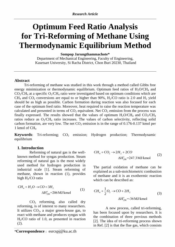
Table 1. Optimum CO2/CH4 and H2O/CH4 ratios at different O2/CH4 ratios and other simulation
results.
Case O2/CH4
ratio Optimum ratio CO2 conversion
(%) H2 yield
(%) H2/CO
ratio CO2/CH4 H2O/CH4 1 0.10 0.282 0.574 90.0 94.943 2.003 2 0.13 0.257 0.500 91.5 94.746 2.003 3 0.16 0.238 0.456 91.0 94.745 2.001 4 0.20 0.212 0.400 90.1 94.744 2.001
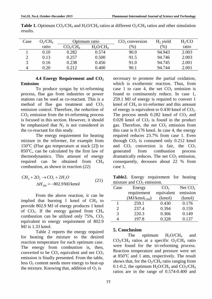
4.4 Energy Requirement and CO2
Emission
To produce syngas by tri-reforming
process, flue gas from industries or power
stations can be used as co-reactant. This is a
method of flue gas treatment and CO2
emission control. Therefore, the reduction of
CO2 emission from the tri-reforming process
is focused in this section. However, it should
be emphasized that N2 is not considered in
the co-reactant for this study.
The energy requirement for heating
mixture in the reformer, for example from
150oC (Flue gas temperature at stack [2]) to
850oC, can be calculated by the first law of
thermodynamics. This amount of energy
required can be obtained from CH4
combustion, as shown in reaction (22)
4 2 2 2
298
2 2
802.9MJ/kmol
CH O CO H O
H
(21)
From the above reaction, it can be
implied that burning 1 kmol of CH4 to
provide 802.9 MJ of energy produces 1 kmol
of CO2. If the energy gained from CH4
combustion can be utilized only 75%, CO2
equivalent to energy requirement of 802.9
MJ is 1.33 kmol.
Table 2 reports the energy required
for heating the mixture to the desired
reaction temperature for each optimum case.
The energy from combustion is, then,
converted to be CO2 equivalent and net CO2
emission is finally presented. From the table,
less O2 content needs more energy to heat-up
the mixture. Knowing that, addition of O2 is
necessary to promote the partial oxidation,
which is exothermic reaction. Thus, from
case 1 to case 4, the net CO2 emission is
found to continuously reduce. In case 1,
259.1 MJ of energy is required to convert 1
kmol of CH4 in tri-reformer and this amount
of energy is equivalent to 0.430 kmol of CO2.
The process needs 0.282 kmol of CO2 and
0.028 kmol of CO2 is found in the product
gas. Therefore, the net CO2 emission from
this case is 0.176 kmol. In case 4, the energy
required reduces 23.7% from case 1. Even
through CO2 is consumed only 0.212 kmol
and CO2 conversion is fair, the CO2
generated from combustion process
dramatically reduces. The net CO2 emission,
consequently, deceases about 22 % from
case 1.
Table2. Energy requirement for heating
mixture and CO2 emission.
Case Energy
requirement
(MJ/kmolCH4)
CO2
equivalent
(kmol)
Net CO2
emission
(kmol) 1 259.1 0.430 0.176 2 237.4 0.394 0.159 3 220.3 0.366 0.149 4 197.8 0.328 0.137
5. Conclusion
The optimum H2O/CH4 and
CO2/CH4 ratios at a specific O2/CH4 ratio
were found for the tri-reforming process.
Reaction temperature and pressure were set
at 850oC and 1 atm, respectively. The result
shows that, for the O2/CH4 ratio ranging from
0.1-0.2, the optimum H2O/CH4 and CO2/CH4
ratios are in the range of 0.574-0.400 and

Thammasat International Journal of Science and Technology Vol.20, No.4, October-December 2015
78
0.282-0.212, respectively. Both optimum
feed ratios reduce when O2/CH4 increases.
The carbon formation was slightly observed
in the optimum operation ranges. For net
CO2 emission, it strongly depends on CO2
equivalent, estimated from heat required to
raise the reaction temperature. Higher O2
content decreases net CO2 effluent. Based on
1 kmol of CH4, net CO2 emitted from the
process is in the range of 0.176-0.137 kmol.
6. References [1] Wang, H. M., Choi, K. S., Kang, I. H.,
Kim, H. M. and Erickson, P. A.,
Theoretical analyses of Autothermal
Reforming Methanol for Use in Fuel
Cell, Journal of Mechanical Science
and Technology, Vol. 20, pp. 864-874,
2006.
[2] Song, C. and Pan, W., Tri-reforming
of Methane: a Novel Concept for
Catalytic Production of Industrially
Useful Synthesis Gas with Desired
H2/CO Rations, Catalysis Today, Vol.
98, pp. 463-484, 2004.
[3] Zhang, Y., Cruz, J., Zhang, S., Lou,
H.H. and Benso., T.J. , Process
Simulation and Optimization of
Methanol Production Coupled to Tri-
reforming Process, International
Journal of Hydrogen Energy, Vol. 38,
pp. 13617-13630, 2013.
[4] Halmann, M. and Steinfeld, A., Fuel
Saving, Carbon Dioxide Emission
Avoidance, and Syngas Production by
Tri-reforming of Flue Gases from
Coal-and Gas-fired Power Stations,
and by the Carbonthermic Reduction
of Iron Oxide, Energy, Vol. 31, pp.
3171-3185, 2006.
[5] Halmann, M. and Steinfeld, A.,
Thermoneutral Tri-reforming of Flue
Gases from Coal-and Gas-fired Power
Stations, Catalysis Today, Vol. 115,
pp. 170-178, 2006.
[6] García-Vargas, J.M., Valverde, J.L.,
de Lucas-Consuegra, A., Go´mez-
Monedero, B., Dorado, F. and
Sánchez, P., Methane tri-reforming
over a Ni/-SiC-based Catalyst:
Optimizing the Feedstock
Composition, International Journal of
Hydrogen Energy, Vol. 38, pp. 4524-
4532, 2013.
[7] ete, B., Gigola, C.E. and Brignole,
N.E., Synthesis Gas Processes for
Methanol Production Via CH4
Reforming with CO2, H2O, and O2.
Industrial & Engineering Chemistry
Research, Vol. 53, pp. 7103-7112,
2014.
[8] Rahimpour, M.R., Arab Aboosadi, Z.
and Jahanmiri, A.H., Synthesis Gas
Production in a Novel Hydrogen and
Oxygen Perm-selective Membranes
Tri-reformer for Methanol Production,
Journal of Natural Gas Science and
Engineering, Vol. 9, pp. 149-159,
2012.
[9] Rahnama, H., Farniaei, M. , Abbasi,
M. and Rahimpour, M.R., Modeling of
Synthesis Gas and Hydrogen
Production in a Thermally Coupling of
Steam and Tri-reforming of Methane
with Membranes, Journal of Industrial
and Engineering Chemistry, Vol. 20,
pp. 1779–1792, 2014.
[10] Mirvakili, A., Heravi, M.,
Karimipourfard, D. and Rahimpour,
M.R., Simultaneous Synthesis Gas and
Styrene Production in the Optimized
Thermally Coupled Reactor, Journal of
Natural Gas Science and Engineering,
Vol. 16, pp. 18-30, 2014.
[11] Jarungthammachote, S. and Dutta, A.,
Equilibrium Modeling of Gasification:
Gibbs Free Energy Minimization
Approach and Its Application to
Spouted Bed and Spout-fluid Bed
Gasifiers, Energy Conversion and
Management, Vol. 49, pp. 1345-1356,
2008.
[12] Jafarbegloo, M., Tarlani, A., Mesbah,
A.W., and Sahebdelfar, S.,
Thermodynamic Analysis of Carbon
Dioxide Reforming of Methane and Its

Vol.20, No.4, October-December 2015 Thammasat International Journal of Science and Technology
79
Practical Relevance, International
Journal of Hydrogen Energy, Vol. 40,
pp. 2445-2451, 2015.
[13] McBride, B. J., Gordon, S. and Reno,
M.A., Coefficients for Calculating
Thermodynamic and Transport
Properties of Individual Species,
NASA., USA., 1993.
[14] Elliiott, J. R. and Lira, C.T.
Introductory Chemical Engineering
Thermodynamics, Prentice-Hall, NJ,
1999.
[15] O’ onn ll, J. P. nd H il , J. M.,
Thermodynamics Fundamentals for
Applications, Cambridge University
Press, New York, 2005.
[16] García-Vargas, J.M., Valverde, J.L.,
Díez, J., Dorado, F., and Sanchez, P.,
Catalytic and Kinetic Analysis of the
Methane Tri-reforming Over a Ni-
Mg/β-SiC Catalyst, International
Journal of Hydrogen Energy, Vol. 40,
pp. 8677-8687, 2015.
[17] Khoshtinat Nikoo, M., and Amin, N.
A. S., Thermodynamic Analysis of
Carbon Dioxide Reforming of
Methane in View of Solid Carbon
Formation, Fuel Processing
Technology, Vol.92, pp. 678–691,
2011.