research article expert control of mine hoist control system
TRANSCRIPT

Research ArticleExpert Control of Mine Hoist Control System
Xiuzhi Liu and Tao Sui
College of Electrical Engineering and Automation, Shandong University of Science and Technology, Qingdao, China
Correspondence should be addressed to Tao Sui; [email protected]
Received 4 February 2021; Revised 20 March 2021; Accepted 7 April 2021; Published 27 April 2021
Academic Editor: Wenqing Wu
Copyright © 2021 Xiuzhi Liu and Tao Sui. This is an open access article distributed under the Creative Commons AttributionLicense, which permits unrestricted use, distribution, and reproduction in any medium, provided the original work isproperly cited.
This paper presents a kind of intelligence control algorithm for the mine hoist control system. Firstly, the desired output of thesystem is described by a speed curve of hoisting process. Then, the structure diagram of the hoist system is constructed, and theexpert PID controller is designed based on the model of this control system; the expert knowledge base was establishedaccording to the analysis of characteristics in different periods of the hoist process. Finally, the control effect was verified bySIMULINK simulation; by comparing with the result of conventional PID control, expert PID control is improved more safeand suitable for the mine hoist control system.
1. Introduction
Mine hoist is mainly used in coal and other mining enter-prises. It is the key equipment in production and is the onlychannel to transport person and material in the mines. Itsperformance directly affects the reliability and safety of pro-duction; once it fails, not only will it seriously damage thedevice but also cause server casualties [1–3]. In this paper,we are concerned on the designing expert control algorithmfor the mine hoist control system.
Expert control is a cross-subject of artificial intelligenceand control theory. It can simulate expert intelligence in anunknown environment and realize effective control. It hasbeen widely used in many industries and provides a newapproach to solve the industrial control problem and realizesindustrial process control. Chen et al. designed a supervisoryexpert controller for ball mill grinding circuits [4]. Shi et al.combined fuzzy PID control and the expert decision to regu-late the temperature and an expert fuzzy PID controller isdesigned [5]. Bergh et al. used expert control in the tuningof an industrial thickener [6]. An intelligent energy-efficientoutdoor lighting control system using an expert system wasdeveloped by Atis and Ekren that could be used in greenbuildings [7]. Bergh et al. designed a predictive expert controlsystem for a hybrid pilot rougher flotation circuit [8]. Belleet al. designed and realized a distributed expert system on a
control strategy to manage the execution flow of rule activa-tion [9]. Di Maioa et al. designed a regional sensitivityanalysis-based expert system for safety margin control [10].Ye et al. used the expert PID to control the valve positioner[11].
Many researchers have been carrying out the research onthe control of the mine hoist system and other DC speed con-trol system; they have obtained some achievements. Hamedet al. designed a fuzzy PID controllers for real-time DCmotor speed control [12, 13]. Liu et al. and Gundogdu et al.used fuzzy PID control and self-tuning PID control in thebrushless DC motor system separately [14, 15]. Ma et al.designed a parameter self-tuning fuzzy PID control for DCmotor [16]. Zdrozis worked on the analysis of abnormalmodes of the hoisting DC electric drive system [17]. Guptaet al. analyzed the applications of artificial intelligence in per-manent magnet brushless DC motor drives [18]. Emhemedand Mamat presented an overview of proportional integralcontrol (PI) and artificial intelligent control (AI) algorithmsfor industrial DC motor [19]. Chang et al. modeled the non-linear DC motor system as Takagi-Sugeno (T-S) fuzzy model[20]. Ulasyar et al. designed an intelligent speed controller forbrushless DC motor (2018) [21].
All these achievements listed above will bring great helpin the research in this paper. This paper adopts expert PIDcontrol in the mine hoist system, by analyzing hoisting
HindawiWireless Communications and Mobile ComputingVolume 2021, Article ID 5592351, 8 pageshttps://doi.org/10.1155/2021/5592351
process in different periods. Based on experiences, expertrules are designed to regulate controller parameters toachieve desired hoist process. Compared with the simulationresults of conventional PID control, it is indicated that expertPID is more suitable for mine hoisting control.
2. Description of Mine Hoist Control System
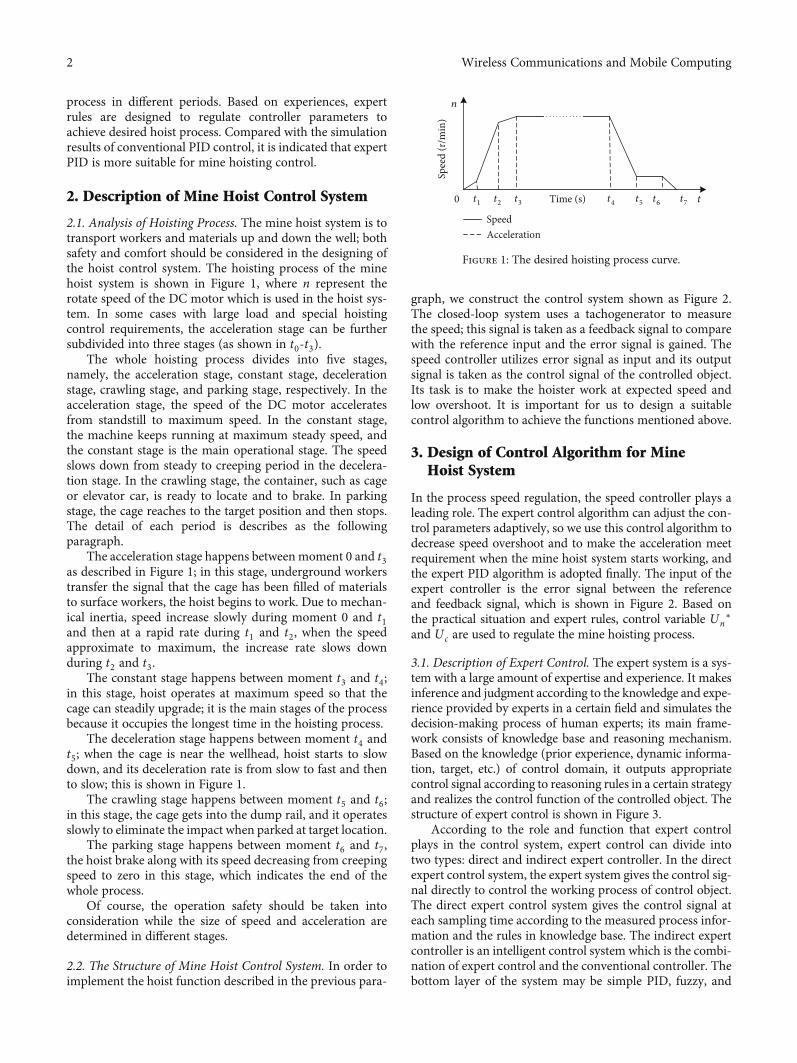
2.1. Analysis of Hoisting Process. The mine hoist system is totransport workers and materials up and down the well; bothsafety and comfort should be considered in the designing ofthe hoist control system. The hoisting process of the minehoist system is shown in Figure 1, where n represent therotate speed of the DC motor which is used in the hoist sys-tem. In some cases with large load and special hoistingcontrol requirements, the acceleration stage can be furthersubdivided into three stages (as shown in t0-t3).
The whole hoisting process divides into five stages,namely, the acceleration stage, constant stage, decelerationstage, crawling stage, and parking stage, respectively. In theacceleration stage, the speed of the DC motor acceleratesfrom standstill to maximum speed. In the constant stage,the machine keeps running at maximum steady speed, andthe constant stage is the main operational stage. The speedslows down from steady to creeping period in the decelera-tion stage. In the crawling stage, the container, such as cageor elevator car, is ready to locate and to brake. In parkingstage, the cage reaches to the target position and then stops.The detail of each period is describes as the followingparagraph.
The acceleration stage happens between moment 0 and t3as described in Figure 1; in this stage, underground workerstransfer the signal that the cage has been filled of materialsto surface workers, the hoist begins to work. Due to mechan-ical inertia, speed increase slowly during moment 0 and t1and then at a rapid rate during t1 and t2, when the speedapproximate to maximum, the increase rate slows downduring t2 and t3.
The constant stage happens between moment t3 and t4;in this stage, hoist operates at maximum speed so that thecage can steadily upgrade; it is the main stages of the processbecause it occupies the longest time in the hoisting process.
The deceleration stage happens between moment t4 andt5; when the cage is near the wellhead, hoist starts to slowdown, and its deceleration rate is from slow to fast and thento slow; this is shown in Figure 1.
The crawling stage happens between moment t5 and t6;in this stage, the cage gets into the dump rail, and it operatesslowly to eliminate the impact when parked at target location.
The parking stage happens between moment t6 and t7,the hoist brake along with its speed decreasing from creepingspeed to zero in this stage, which indicates the end of thewhole process.
Of course, the operation safety should be taken intoconsideration while the size of speed and acceleration aredetermined in different stages.
2.2. The Structure of Mine Hoist Control System. In order toimplement the hoist function described in the previous para-
graph, we construct the control system shown as Figure 2.The closed-loop system uses a tachogenerator to measurethe speed; this signal is taken as a feedback signal to comparewith the reference input and the error signal is gained. Thespeed controller utilizes error signal as input and its outputsignal is taken as the control signal of the controlled object.Its task is to make the hoister work at expected speed andlow overshoot. It is important for us to design a suitablecontrol algorithm to achieve the functions mentioned above.
3. Design of Control Algorithm for MineHoist System
In the process speed regulation, the speed controller plays aleading role. The expert control algorithm can adjust the con-trol parameters adaptively, so we use this control algorithm todecrease speed overshoot and to make the acceleration meetrequirement when the mine hoist system starts working, andthe expert PID algorithm is adopted finally. The input of theexpert controller is the error signal between the referenceand feedback signal, which is shown in Figure 2. Based onthe practical situation and expert rules, control variable Un
∗
and Uc are used to regulate the mine hoisting process.
3.1. Description of Expert Control. The expert system is a sys-tem with a large amount of expertise and experience. It makesinference and judgment according to the knowledge and expe-rience provided by experts in a certain field and simulates thedecision-making process of human experts; its main frame-work consists of knowledge base and reasoning mechanism.Based on the knowledge (prior experience, dynamic informa-tion, target, etc.) of control domain, it outputs appropriatecontrol signal according to reasoning rules in a certain strategyand realizes the control function of the controlled object. Thestructure of expert control is shown in Figure 3.
According to the role and function that expert controlplays in the control system, expert control can divide intotwo types: direct and indirect expert controller. In the directexpert control system, the expert system gives the control sig-nal directly to control the working process of control object.The direct expert control system gives the control signal ateach sampling time according to the measured process infor-mation and the rules in knowledge base. The indirect expertcontroller is an intelligent control system which is the combi-nation of expert control and the conventional controller. Thebottom layer of the system may be simple PID, fuzzy, and
n
Time (s)
AccelerationSpeed
Spee
d (r
/min
)
tt1 t2 t3 t4 t5 t6 t70
Figure 1: The desired hoisting process curve.
2 Wireless Communications and Mobile Computing

Powerelectronicconverter
Mine hoistSpeedcontroller
Sensor
Controlled object
Un⁎
n
Un
e Uc
Figure 2: The structure diagram of the mine hoist control system.
Expertknowledge
Human-computer interface
Knowledge database
Real time inferencemachine
Dynamic database
Reasoningmechanism
Information acquisition and processing
Figure 3: The basic structure of the expert control system.
Knowledge base
Real-time inference
engine
Control algorithms
library
Acquire and handle information
Controlled object
Sensor
Direct expert controller
Figure 4: The direct expert controller.
Expert system
Control algorithm Controlobject
Sensor
Indirect expert controller
Figure 5: The indirect expert controller.
Table 1: Parameters of the system.
Parameter Value
Nominal voltage UN (V) 750
Nominal current IN (A) 760
Nominal speed IN (r/min) 375
Electromotive force coefficient (V·r/min) 1.82
Magnification factor of the thyristor device Ks 75
Resistance of armature circuit R (Ω) 0.14
Time constants T l (s) 0.031
Time constants Tm (s) 0.112
Feedback coefficient of speed α 0.027
Maximum given input Unm∗(V) 10
∗Corresponds to the nominal speed.
3Wireless Communications and Mobile Computing

other algorithms, and expert control is used to adjust theparameters of the bottom layer algorithm. The structure ofdirect expert control system and indirect expert controlsystem is shown as shown in Figures 4 and 5, respectively.
This paper chooses an expert PID controller to replacethe conventional PID controller as the outer controller tocontrol the hoist process. This controller is one kind of indi-rect controller. Expert control can adjust the parameters ofPID controller adaptively according to the size of systemdeviation. The key problem of the outer controller design isto design expert control rules to improve the dynamicperformance of the system at startup.
3.2. The Design of Expert Controller. The function of theexpert controller is to make the hoisting process as shown inFigure 1. The acceleration during the start and stop processis neither too large nor too small, which will ensure both com-fort and safety. The integral separation algorithm is adoptedwhen expert rules are designed. When the error is large, openloop control is adopted, and the output of control is fixed toreduce the error quickly. When the error reduces to a certainrange, PID control is adopted, and the parameters of the
PID controller are adjusted accordingly with the size of theerror. Several related parameters need to be defined beforedesigning rules as that is shown in the following paragraph.
Error boundM1 andM2,M1 >M2 > 0. When the error isbigger than M1, several error threshold are defined as aiði =1, 2,⋯,nÞ, a1 > a2 >⋯ > an, the value of n is determined bythe characteristics of control objectives, The output of thecontroller is biði = 1, 2,⋯,nÞ corresponding to ai, When the
0 10 20 30 40 50Time (s)
n⁎0.
027
12
10
8
6
4
2
0
−2
(a)
2
0
4
6
8
10
0 0.5 1.5 21Time (s)
n⁎0.
027
12
3
4
(b)
Figure 6: Output curve with conventional PID control (ki = 0:1).
0 10 20 30 40 50Time (s)
12
10
8
6
4
2
0
−2
n⁎0.
027
(a)
0.5 1 1.5 2 2.5 3
9.6
9.8
10
10.2
10.4
Time (s)
21
n⁎0.
027
3 4
(b)
Figure 7: Output curve with conventional PID control (kp = 1:2).
Table 2: Response parameter of the system.
ki kp Vmax tmax (s) No. of curve
0.1
2.0 10.75 0.262 1st in Figure 6
1.2 10.13 0.037 2st in Figure 6
1.0 10.05 0.496 3rd in Figure 6
0.5 10.25 1.232 4th in Figure 6
0.2
0.12
10.4 0.388 1st in Figure 7
0.3 10.34 0.386 2st in Figure 7
0.4 10.27 0.384 3rd in Figure 7
0.5 10.2 0.386 4th in Figure 7∗Vmax is the maximum speed feedback signal.
4 Wireless Communications and Mobile Computing

absolute value of error is greater than ai, bi is a constantvalue, and the control mode of the system is open loop con-trol. When the error is smaller than M1, the PID controllerworks, and several parameters are defined as follows: propor-tional parameter kp, integral parameter ki, differential param-eter kd , amplification gain coefficient k1 > 1, Inhibitioncoefficient 0 < k2 < 1, at k and k-1 times, error is e ðkÞ and eðk − 1Þ, controller output is u ðkÞ and u ðk − 1Þ.
Expert control rules of mine hoisting system are designedas follows:
When jeðkÞj ≥M1 , n = 4, in order to get the desired start-ing process, the value of bi (i = 1, 2, 3, 4) is as b1 < b2, b2 > b3,b3 > b4, accurate values adjust according to the control needs.
If jeðkÞj > a1 , then u ðkÞ = b1.If jeðkÞj > a2 , then u ðkÞ = b2.If jeðkÞj > a3 , then u ðkÞ = b3.If jeðkÞj > a4 , then u ðkÞ = b4.When jeðkÞj <M1 , PI control works; if the error is higher
and its absolute value gradually increases, the regulator
should implement stronger control; if the error is lower andits absolute value increase, then implement general controlto correct the tendency. If the absolute value decreases orthe system are in the state of balance, the regulator imple-ment according to conventional PID parameters.
If eðkÞΔeðkÞ > 0 and jeðkÞj ≥M2 , then uðkÞ = uðk − 1Þ+ k1kpeðkÞ.
0 10 20 30 40 50Time (s)
12
10
8
6
4
2
0
−2
n⁎0.
027
Figure 8: Output curve with expert PID.
0 10 20 30 40 50Time (s)
12
10
8
6
4
2
0
−2
n⁎0.
027
(a)
2
1.5 2.5 3 3.5 42
3
4
5
6
7
8
9n⁎0.
027
Time (s)
3
2
6
6
4
1
(b)
Figure 9: Output curves with variable parameters of expert PID. (a) Six output curves of the whole working process correspond to sixdifferent values of b2 shown in line 1 to line 6. (b) Corresponding starting processes.
Table 3: The value of the acceleration.
b2 Sl No. of curve
0.3 6.740 1st in Figure 9
0.4 5.746 2st in Figure 9
0.5 5.250 3rd in Figure 9
0.55 4.753 4th in Figure 9
0.6 3.760 5th in Figure 9
0.7 2.767 6th in Figure 9
5Wireless Communications and Mobile Computing

If eðkÞΔeðkÞ > 0 and jeðkÞj <M2 , then uðkÞ = uðk − 1Þ+ k2kpeðkÞ.
If eðkÞΔeðkÞ < 0 and ΔeðkÞΔeðk − 1Þ < 0 or jeðkÞj = 0,then uðkÞ = uðk − 1Þ.
If eðkÞΔeðkÞ < 0 and ΔeðkÞΔeðk − 1Þ < 0 and jeðkÞj ≥M2 ,then uðkÞ = uðk − 1Þ + k1kpeðkÞ.
If eðkÞΔeðkÞ < 0 and ΔeðkÞΔeðk − 1Þ < 0 and jeðkÞj <M2 ,then uðkÞ = uðk − 1Þ + k2kpeðkÞ.
If the absolute value of error is small enough, in order todecrease final error, conventional PI control is needed.
If jeðkÞj ≤ ε , then uðkÞ = kpeðkÞ + kiðeðkÞ + eðk − 1ÞtsÞ.
4. Simulation Analysis
The simulation model is established based on a speed regula-tion circuit of the SCR-D system. The basic parameters areshown in Table 1.
4.1. Control by the Conventional PID Algorithm. From thegiven parameters mentioned above, we can get the errorrange is (0, 10), and output range of controller is (0, 1).Now, two kinds of control methods are used to the motorcontrol system, one is an ordinary PID controller andanother is an expert PID controller, and their control effectswill be compared.
The given input signal curve and the corresponding out-put response curve of the system when the PI controller isused is shown in Figures 6 and 7, (a) is the output curve ofthe whole working process and (b) describes starting process.
In order to show the control effect, we unify the input andoutput signals into the same dimension. There are fouroutput curves of the system both in Figures 6 and 7.
From the result get from Figures 6 and 7, we can find theacceleration in the starting process is large and overweightand weightlessness can be greater and the strain on the cablewill be large. Although we can reduce acceleration and over-shoot by reducing kp or ki, this will increase the error.
The respond parameter to different controller parametersis listed in Table 2.
4.2. Control by the Expert PID Algorithm. When expert PIDalgorithm is adopted, according to the expert rules, parame-ters are selected as follows:
a1 = 8:0, a2 = 1:5, a3 = 0:5, a4 = 0:01 ;b1 = 0:2, b2 = 0:55, b3 = 0:12, b4 = 0:05 ;
k1 = 2, k2 = 0:4 ;kp = 60, ki = 11:5, kd = 0:01:
ð1Þ
When a given signal is descending for deceleration, theparameters a and b are turned into negative values of theresponse. The system response curve and the given inputcurve are shown as Figure 8.
Apparently, the curve in Figure 8 close to the ideal hoistprocess shown in Figure 1, that is, expert control is suitablefor mine hoist control system.
20
9.5
10
10.5
Time (s)2221 23 24
n⁎0.
027
(a)
20
9.5
10
10.5
11
Time (s)2221 23 24
n⁎0.
027
(b)
Figure 10: Impact of sudden load increase.
88.5
9
9.5
10
10.5
11
Time (s)1210 14 16
n⁎0.
027
(a)
9.5
8 9 10 11Time (s)
12 13 14
10
10.5
11
n⁎0.
027
(b)
Figure 11: Impact of sudden load drop.
6 Wireless Communications and Mobile Computing

If we want to change the acceleration of the startup pro-cess, we can change b2, it plays a major role in the startingprocess. Increasing b2 can increase the starting acceleration,it can be shown by Figure 9.
The relationship between the performance index in thesystem startup process in Figure 9 and the value of b2 isshown in Table 3.
In Table 3, sl represent the slope of the of output curvewhen the output of expert controller is b2.
In the designing of the expert controller of the mine hoistcontrol system, the value of b2 is determined by the object tobe transported. For example, for the system of transportingpeople, comfort is more important, the value of b2 shouldbe smaller, and for system of transporting cargo, speed ismore important, the value of b2 should be larger.
4.3. Effect of Load Mutation. Since the hoist is generallyhoisted by a steel wire rope, which has certain elasticity,and load fluctuation may occur during operation, so thisstudy adds the interference of load mutation.
In the period of constant speed operation (10 s, 12 s) and(20 s, 22 s), when the torque is increased by 30 or dropped by30, the system will fluctuate slightly. The results are shown inFigures 10 and 11.
It can be seen from the figures that whether the load sud-denly increases or decreases, both of these methods can effec-tively inhibit the effect of load mutation. Both of thesemethods can inhibit the effect of load mutation. However,the output curve of the system with expert PID algorithmfluctuates less (as shown in Figures 10 and 11(a)), while thecurve of the system with PID algorithm fluctuates more (asshown in Figures 10 and 11(b)).
5. Conclusions
This paper is concerned with the research on the applicationof expert control on the DC speed control system, and themine hoist control system which uses a DC motor is takenas the control object. By comparing the control result of con-ventional PID control the expert control, we can find thatexpert control is more suitable for the hoist control system.Firstly, the hoisting and stopping acceleration of the hoistsystem by expert control is less than the system which is con-trolled by conventional PI controller, and this will greatlyimprove comfort level of the people; this will also improvethe safety of the system for smaller acceleration can reducethe strain on the cable. Secondly, the expert control minehoist control system can be designed as having no overshot,although conventional PID control can also make the systemhaving no overshot, but on this situation, the acceleration willbe much larger and the system may be not safe. Whendesigning an expert controller for a mine hoist control sys-tem, both the comfort and the safety should be considered,which are determined by the sense of overweight and weight-lessness and the strain of the cable separately, and these areall determined by the acceleration during the starting andstopping period, the rules of expert controller and the controlparameters are all determined by the facts mentioned above.It is need to be said that the expert rules in this paper is not
necessarily suitable other motor control system, especiallythe system that need positive and negative rotation and needchanging frequently. Of course, this method could beextended to other applications, such as the elevators, thehoisting machines.
Data Availability
The data that support the findings of this study are availablefrom the corresponding author upon reasonable request.
Conflicts of Interest
The authors declare that they have no conflicts of interest.
Acknowledgments
This paper is supported by the Shandong university scientificresearch development plan project (J18KA317) and the Min-istry of Education Industry-University Cooperation Collabo-rative Education Project (201802060023, 201901040028).
References
[1] S. Xue, J. Tan, L. Shi, and J. Deng, “Rope tension fault diagnosisin hoisting systems based on vibration signals using EEMD,improved permutation entropy, and PSO-SVM,” Entropy,vol. 22, no. 2, p. 209, 2020.
[2] N. Vayenas and S. Peng, “Reliability analysis of undergroundmining equipment using genetic algorithms,” Journal of Qual-ity in Maintenance Engineering, vol. 20, no. 1, pp. 32–50, 2014.
[3] X. Li, Q. Pan, and K. He, “Modeling and analysis of harmonicin the mine hoist cnverter based on double closed-loop con-trol,” Journal of Computers, vol. 7, no. 6, pp. 1353–1360, 2012.
[4] X. Chen, Q. Li, and S. Fei, “Supervisory expert control for ballmill grinding circuits,” Expert Systems with Applications,vol. 34, no. 3, pp. 1877–1885, 2008.
[5] D. Shi, G. Gao, Z. Gao, and P. Xiao, “Application of expertfuzzy PIDmethod for temperature control of heating furnace,”Procedia Engineering, vol. 29, pp. 257–261, 2012.
[6] L. Bergh, P. Ojeda, and L. Torres, “Expert control tuning of anindustrial thickener,” IFAC-Papers OnLine, vol. 48, no. 17,pp. 86–91, 2015.
[7] S. Atis and N. Ekren, “Development of an outdoor lightingcontrol system using expert system,” Energy and Buildings,vol. 130, pp. 773–786, 2016.
[8] L. Bergh, J. Yianatos, J. Olivares, and J. Durán, “Predictiveexpert control system of a hybrid pilot rougher flotation cir-cuit,” IFAC-PapersOnLine, vol. 49-20, pp. 155–160, 2016.
[9] A. Boaye Belle, T. C. Lethbridge, M. Garzón, and O. O. Ade-sina, “Design and implementation of distributed expert sys-tems: on a control strategy to manage the execution flow ofrule activation,” Expert Systems with Applications, vol. 96,pp. 129–148, 2018.
[10] F. di Maio, A. Bandini, M. Damato, and E. Zio, “A regionalsensitivity analysis-based expert system for safety marginscontrol,” Nuclear Engineering and Design, vol. 330, pp. 400–408, 2018.
[11] L. Ye, X.-b. Wang, and W. Xin, “A type of control methodbased on expert PID for intelligent valve positioner,” ControlEngineering of China, vol. 26, no. 1, pp. 87–91, 2019.
7Wireless Communications and Mobile Computing

[12] B. Hamed and M. Almobaied, “Fuzzy PID controllers usingFPGA technique for real time DC motor speed control,” Intel-ligent Control & Automation, vol. 2, no. 3, pp. 233–240, 2011.
[13] S. Abel, G. Erdem, M. Amanullah, M. Morari, M. Mazzotti,and M. Morbidelli, “Optimizing control of simulated movingbeds–experimental implementation,” Journal of Chromatogra-phy A, vol. 1092, no. 1, pp. 2–16, 2005.
[14] G. Liu, J. Min, and Q. Sheng, “Brushless DC motor fuzzy PIDcontrol system and simulation,” Sensors & Transducers Jour-nal, vol. 181, no. 10, pp. 111–116, 2014.
[15] T. Gundogdu and G. Komurgoz, “Self-tuning PID control of abrushless DCmotor by adaptive interaction,” Ieej Transactionson Electrical & Electronic Engineering, vol. 9, no. 4, pp. 384–390, 2014.
[16] Y. Ma, Y. Liu, and C. Wang, “Design of parameters self-tuningfuzzy PID control for DC motor,” in International Conferenceon Industrial Mechatronics and Automation, pp. 345–348,Wuhan, China, 2010.
[17] K. Zdrozis, “Analysis of abnormal modes of hoisting DC elec-tric drive System,” American Journal of Applied Sciences, vol. 7,no. 4, pp. 527–534, 2010.
[18] R. A. Gupta, R. Kumar, and A. K. Bansal, “Artificial intelli-gence applications in permanent magnet brushless DC motordrives,” Artificial Intelligence Review, vol. 33, no. 3, pp. 175–186, 2010.
[19] A. A. A. Emhemed and R. B. Mamat, “Modelling and simula-tion for industrial DC motor using intelligent control,” Proce-dia Engineering, vol. 41, pp. 420–425, 2012.
[20] X. Chang, Y. Wang, X. H. Chang, and Y. M. Wang, “Peak-to-peak filtering for networked nonlinear DCmotor systems withquantization,” IEEE Transactions on Industrial Informatics,vol. 14, no. 12, pp. 5378–5388, 2018.
[21] A. Ulasyar, H. S. Zad, and A. Zohaib, “Intelligent speed con-troller design for brushless DC motor,” International Confer-ence on Frontiers of Information Technology, pp. 19–23,Islamabad, Pakistan, December 2018.
8 Wireless Communications and Mobile Computing