mine redevelopment erosion and sediment control plan
TRANSCRIPT

1.
Rustler’s Roost & Quest 29 Open-Cut Mine Redevelopment
Erosion and Sediment Control Plan Volume 4: Appendix D.1 to Appendix H.1
September 2021
RELIANCE, USES and LIMITATIONS This report is copyright and is to be used only for its intended purpose by the intended recipient and is not to be copied or used in any other way. The report may be relied upon for its intended purpose within the limits of the following disclaimer.
This study, report and analyses have been based on the information available to Surface Water & Erosion Solutions and Elder Enviro Pty Ltd at the time of preparation. Surface Water & Erosion Solutions and Elder Enviro Pty Ltd accepts responsibility for the report and its conclusions to the extent that the information was sufficient and accurate at the time of preparation. Surface Water & Erosion Solutions and Elder Enviro Pty Ltd do not take responsibility for errors and omissions due to incorrect information or information not available at the time of preparation of the study, report, or analyses.
Photograph Cover Sheet: Rustler’s Roost Pit looking north July 2021. Photograph: K Evans 2021

ACRONYMS & ABBREVIATIONS
BOM CPEng CPESC EMSP ESCP IECA LOM ML MMP NT RR TSF WMP WRD
Bureau of Meteorology Chartered Professional Engineer Certified Professional in Erosion and Sediment Control Environmental Management System and Plans Erosion and Sediment Control Plan International Erosion Control Association Life of Mine Mineral Lease Mining Management Plan Northern Territory Rustler’s RoostTailing Storage Facility Water Management Plan Waste rock dump

TABLE OF CONTENTS
Appendix A.3 Topography - Q29 & Accommodation Camp .......................................................................... 9
Appendix B.1 Infrastructure Layout post-mining at RR and Q29 ................................................................. 11
Appendix C.1 Site Flow Accumulation, RUSLE Soil Loss & Sediment Basin Requirements – Final .......... 13
Appendix C.2 Q29 Maximum operational and rehabilitated soil loss. ......................................................... 15
Appendix D.1 RR Catchments and Drainage at Stage 1 ............................................................................. 17
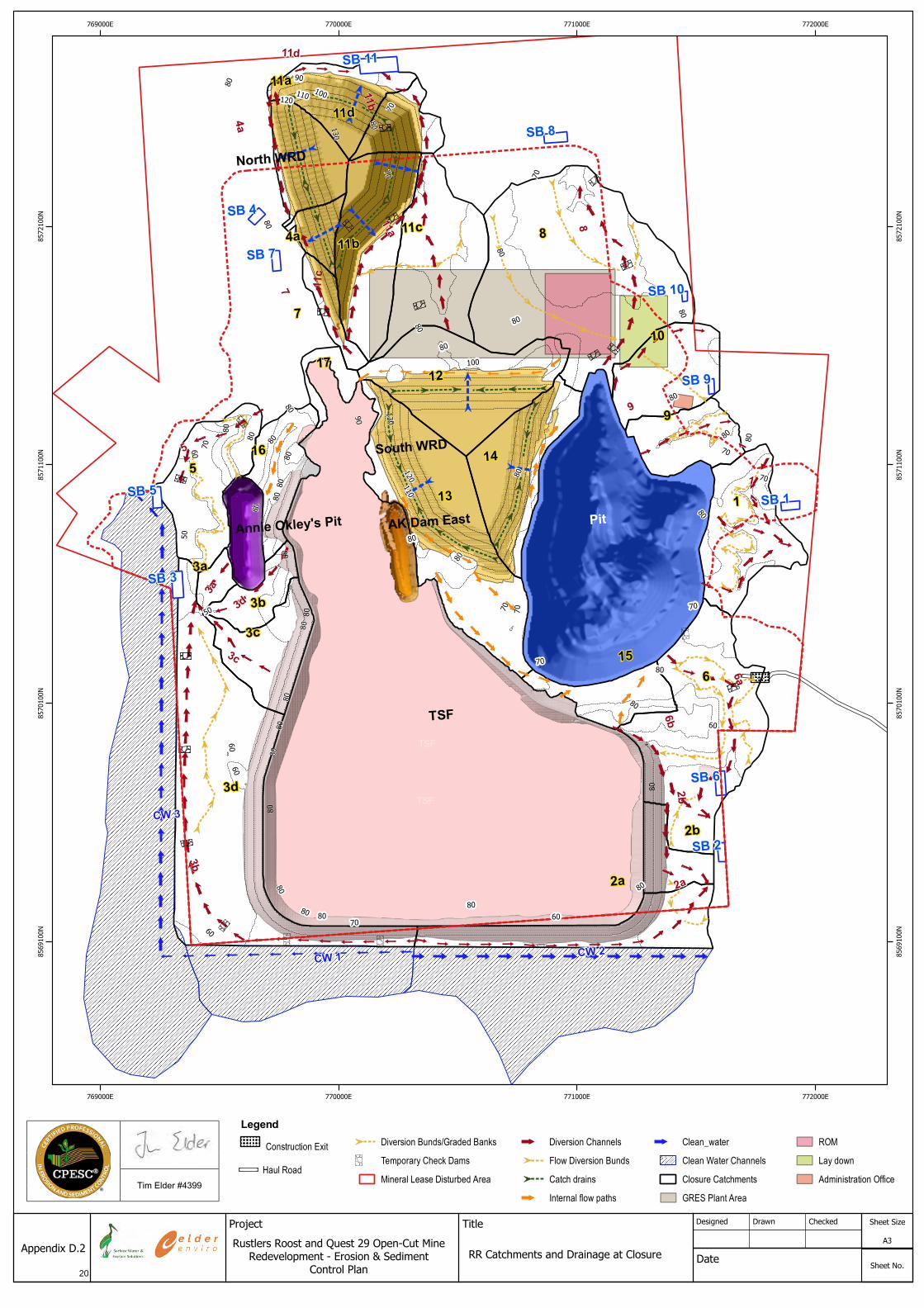
Appendix D.2. RR Catchments and Drainage at Closure ............................................................................ 19
Appendix D.3. Flow Diversion Bank Calculations RR.. ................................................................................ 21
Appendix D.4. Q29 Flow Diversion Bank Calculations at Closure .............................................................. 23
Appendix D.5. Quest 29 Conceptual Drainage Layout at closure. .............................................................. 25
Appendix D.6 Typical ESC Designs............................................................................................................. 27
Appendix E.1 Sediment Basin Type D Detail. ............................................................................................. 29
Appendix E.2 Sediment Basin Emergency Spillway Detail ......................................................................... 31
Appendix E.3 Standard Drawing Chute and Energy.................................................................................... 33
Appendix F.1 Construction Exit Grid Detail - IECA 2009 ............................................................................. 35
Appendix G.1 Collected soil samples and laboratory analysis .................................................................... 37
Appendix H.1 Site Inspection Checklist - IECA 2008 .................................................................................. 39

Appendix D.1 RR Catchments and Drainage at Stage 1
17

Construction Exit
Haul Road
Diversion Bunds/Graded Banks
Temporary Check Dams
Mineral Lease Disturbed Area
Diversion Channels
Flow Diversion Bunds
Catch drains
Internal flow paths
Clean_water
Clean Water Channels
Closure Catchments
GRES Plant Area
ROM
Lay down
Administration Office
Legend
Appendix D.1
DesignedProject Title Drawn
Date
Checked Sheet Size
A3
Sheet No.
Tim Elder #4399
Rustlers Roost and Quest 29 Open-Cut Mine Redevelopment - Erosion & Sediment
Control Plan
RR Catchments and Drainage at Stage 1
18
Annie Oakley's Pirt

Appendix D.2. RR Catchments and Drainage at Closure
19
Construction Exit
Haul Road
Diversion Bunds/Graded Banks
Temporary Check Dams
Mineral Lease Disturbed Area
Diversion Channels
Flow Diversion Bunds
Catch drains
Internal flow paths
Clean_water
Clean Water Channels
Closure Catchments
GRES Plant Area
ROM
Lay down
Administration Office
Legend
Appendix D.2
DesignedProject Title Drawn
Date
Checked Sheet Size
A3
Sheet No.
Tim Elder #4399
Rustlers Roost and Quest 29 Open-Cut Mine Redevelopment - Erosion & Sediment
Control PlanRR Catchments and Drainage at Closure
20

Appendix D.3. Flow Diversion Bank Calculations RR
21

B
LEGEND: LEGEND:
A3Title
RRPA Flow Diversion Bank Calculations
KGE KGE
DrawnDesigned Checked Sheet Size
Sheet No
KGE
Date:
Project
Appendix D.3
Across Flow Diversion Banks for Stage 1
1. Across flow diversion banks were design based on the current slope of the catchment and assumingthe whole catchment will be disturbed.
2. The design storm is the 10% AEP event derived from BOM IFDs.3. The upstream channel side slope in the table is the same as the current grade taken from the
available digital elevation model (DEM).4. A 0.2% grade was applied to the longitudinal flow direction of the bank.5. A Manning's n of 0.06 was applied in determining bank dimensions to reflect large rock fragments
that my be present.6. These calculation and bank requirements should reassess once operations commence and a definite
timetable of disturbance is available.7. The outflow of the banks should enter the diversion channels conveying drainage downslope.8. For installation, maintenance and removal details see IECA standard drawing Flow Diversion Banks
DB-01 https://austieca.com.au/documents/item/86
DRAF
Design peak
Offsite Clean Water Flow Diversion Banks
1. See Appendix D.1 for location.2. The design storm is the 10% AEP event derived from BOM IFDs.3. There are 4 offsite catchments where water may flow onto the site and mix with mine site water.4. Diversion banks should be constructed to divert the clean water away from the site.5. A Manning's n = 0.04 was applied for the natural site.6. The upstream side slope given in the table are those of the natural surface.7. The bank should be constructed from the mine site so that the offsite catchment is not disturbed.8. These calculation and bank requirements should reassess once operations commence and a
definite timetable of disturbance is available.
Rustler's Roost Project Area Erosion & Sediment Control Plan.
Tim Elder #4399
Flow Calculations for Stage 1 ESCP
1. Flow calculations were conducted using the Rational Formula and the methods in IECA (2008).2. Catchment areas where taken of the DEM for the current RRPA site conditions.3. These calculation and bank requirements should be reassessed once operations commence and a definite
timetable of disturbance is available.
Diversion Channel Calculations
1. The design storm peak discharge is for the 10% AEP event derived using the Rational Formula (IECA 2008)2. These calculation and bank requirements should be reassess once operations commence and a definite timetable of
disturbance is available.3. For installation, maintenance and removal details see IECA standard drawing Diversion Channels DC-01 https://
austieca.com.au/documents/item/83
22

Appendix D.4. Q29 Flow Diversion Bank Calculations at Closure
23

B
LEGEND: LEGEND:
A3Title
RRPA Flow Diversion Bank Calculations at Closure
KGE KGE
DrawnDesigned Checked Sheet Size
Sheet No
KGE
Date:
Project
Appendix D.4
DRAF
Design peak
Rustler's Roost Project AreaErosion & Sediment Control Plan.
Tim Elder #4399
Flow Calculations for the Closure Landform
1. Flow calculations were conducted using the Rational Formula and the methods in IECA(2008).
2. Catchment areas where taken of the DEM for the final landform.3. These calculations should be reassessed for each updated ESCP thoughout the LOM.
Diversion Channel Calculations
1. The design storm peak discharge is for the 10% AEP event derived using the Rational Formula (IECA 2008)2. These calculation and channel requirements should be reassessed once operations commence and with each
update of the ESCP.3. For installation, maintenance and removal details see IECA standard drawing Diversion Channels DC-01 https://
austieca.com.au/documents/item/83
24

Appendix D.5. Quest 29 Conceptual Drainage Layout at closure
25

Project Title
Rustlers Roost and Quest 29 Open-Cut MineRedevelopment - Erosion & Sediment Control Plan
Designed
Quest 29 Conceptual Drainage Layout
Drawn Checked
Date
Sheet size
Sheet No.Sheet of
Appendix D.5
Tim Elder #4399
Flow Calculations for the Closure Landform
1. Flow calculations were conducted using the Rational Formula and the methods in IECA (2008).2. Catchment areas where taken of the DEM for the final landform.3. These calculations should be reassessed for each updated ESCP thoughout the LOM.
Diversion Channel Calculations
1. The design storm peak discharge is for the 10% AEP event derived using the Rational Formula (IECA 2008)2. These calculation and channel requirements should be reassessed once operations commence and with each update of
the ESCP.3. For installation, maintenance and removal details see IECA standard drawing Diversion Channels DC-01 https://
austieca.com.au/documents/item/83
Clean Water Flow Diversion Banks
1. The design storm is the 10% AEP event derived from BOM IFDs.2. There are 4 off-site catchments where water may flow onto the site and mix with mine site water.3. For installation, maintenance and removal details see IECA standard drawing Flow Diversion Banks DB-01 https://
austieca.com.au/documents/item/864. These calculation and bank requirements should reassess once operations commence and a definite timetable of
disturbance is available.
Sand deposi on Gulungul Ck
Closure Landform
Pit
WRD
HL Cover
Development_envelope
Mineral Lease Disturbed Area
Clean Water
Sediment Basin
Stream Channel
Diversion Channel
26

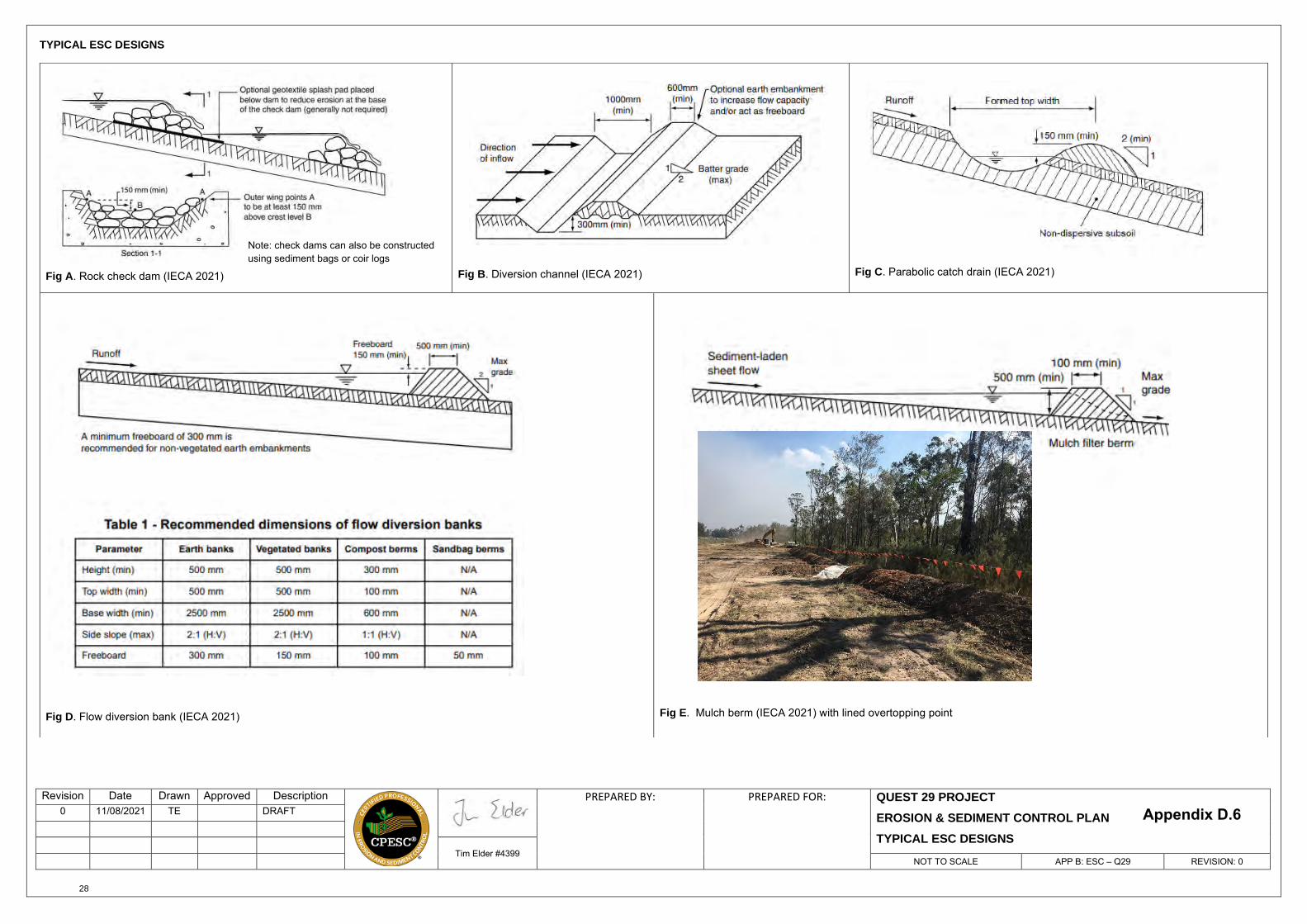
Appendix D.6 Typical ESC Designs
27
Revision Date Drawn Approved Description PREPARED BY: PREPARED FOR: QUEST 29 PROJECT EROSION & SEDIMENT CONTROL PLAN TYPICAL ESC DESIGNS
0 11/08/2021 TE DRAFT
Tim Elder #4399NOT TO SCALE APP B: ESC – Q29 REVISION: 0
TYPICAL ESC DESIGNS
Fig A. Rock check dam (IECA 2021) Fig B. Diversion channel (IECA 2021) Fig C. Parabolic catch drain (IECA 2021)
Fig D. Flow diversion bank (IECA 2021) Fig E. Mulch berm (IECA 2021) with lined overtopping point
Note: check dams can also be constructed using sediment bags or coir logs
Appendix D.6
28

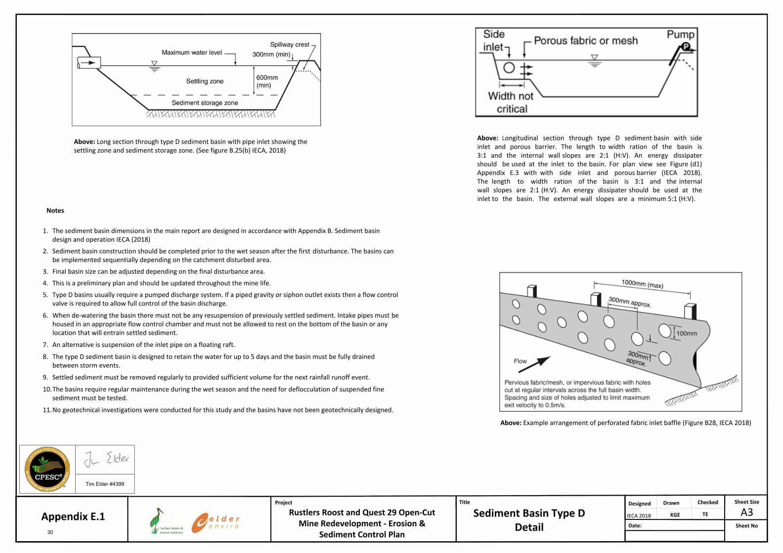
Appendix E.1 Sediment Basin Type D Detail.
29
B
LEGEND: LEGEND:
A3Title
Sediment Basin Type D Detail
KGE TE
DrawnDesigned Checked Sheet Size
Sheet NoDate:
Project
Rustlers Roost and Quest 29 Open-Cut Mine Redevelopment - Erosion &
Sediment Control Plan
Appendix E.1
1. The sediment basin dimensions in the main report are designed in accordance with Appendix B. Sediment basindesign and operation IECA (2018)
2. Sediment basin construction should be completed prior to the wet season after the first disturbance. The basins canbe implemented sequentially depending on the catchment disturbed area.
3. Final basin size can be adjusted depending on the final disturbance area.
4. This is a preliminary plan and should be updated throughout the mine life.
5. Type D basins usually require a pumped discharge system. If a piped gravity or siphon outlet exists then a flow controlvalve is required to allow full control of the basin discharge.
6. When de-watering the basin there must not be any resuspension of previously settled sediment. Intake pipes must behoused in an appropriate flow control chamber and must not be allowed to rest on the bottom of the basin or anylocation that will entrain settled sediment.
7. An alternative is suspension of the inlet pipe on a floating raft.
8. The type D sediment basin is designed to retain the water for up to 5 days and the basin must be fully drainedbetween storm events.
9. Settled sediment must be removed regularly to provided sufficient volume for the next rainfall runoff event.
10.The basins require regular maintenance during the wet season and the need for deflocculation of suspended finesediment must be tested.
11.No geotechnical investigations were conducted for this study and the basins have not been geotechnically designed.
Above: Longitudinal section through type D sediment basin with side inlet and porous barrier. The length to width ration of the basin is 3:1 and the internal wall slopes are 2:1 (H:V). An energy dissipater should be used at the inlet to the basin. For plan view see Figure (d1) Appendix E.3 with with side inlet and porous barrier (IECA 2018). The length to width ration of the basin is 3:1 and the internal wall slopes are 2:1 (H:V). An energy dissipater should be used at the inlet to the basin. The external wall slopes are a minimum 5:1 (H:V).
Above: Example arrangement of perforated fabric inlet baffle (Figure B28, IECA 2018)
Above: Long section through type D sediment basin with pipe inlet showing the settling zone and sediment storage zone. (See figure B.25(b) IECA, 2018)
Notes
Tim Elder #4399
IECA 2018
30

Appendix E.2 Sediment Basin Emergency Spillway Detail
31

B
LEGEND: LEGEND:
A3Title
Sediment Basin Emergency Spillway Detail
KGE KGE
DrawnDesigned Checked Sheet Size
Sheet No
KGE
Date:
Project
Rustlers Roost and Quest 29 Open-Cut Mine Redevelopment - Erosion &
Sediment Control Plan
Appendix E.2
Plan view layout of the emergency spillway to be designed to a 2% AEP event as the basins design life is > 12 months. Construction, maintenance and removal detail are available in in Drawing CH-06 (IECA, 2008), https://austieca.com.au/documents/item/80.
Sediment basin type D exit spillway (Figure B36 IECA, 2018). See Appendix E.3 for energy dissipaters and drainage chutes.
Notes1. The emergency spillway has a trapezoidal profile.
2. See Main report sediment basin size schedule for emergency spillway design parameters.
3. The design storm is the 2% AEP event peak discharge determine from BOM IFDs inaccordance with IECA (2008) guidelines.
Relationship between the emergency spillway and the energy dissipater for a Type C sediment basin which can similarly apply to the type D sediment basin (Figure B9, IECA, 2008).
Tim Elder #4399
32

Appendix E.3 Standard Drawing Chute and Energy
33

B
LEGEND: LEGEND:
A3Title
Standard Drawing Chute and Energy Dissipater detail (IECA 2009)
KGE KGE
DrawnDesigned Checked Sheet Size
Sheet No
KGE
Date:
ProjectRustlers Roost and Quest 29 Open-Cut Mine
Redevelopment - Erosion & Sediment Control Plan
Appendix E.334

Appendix F.1 Construction Exit Grid Detail - IECA 2009
35
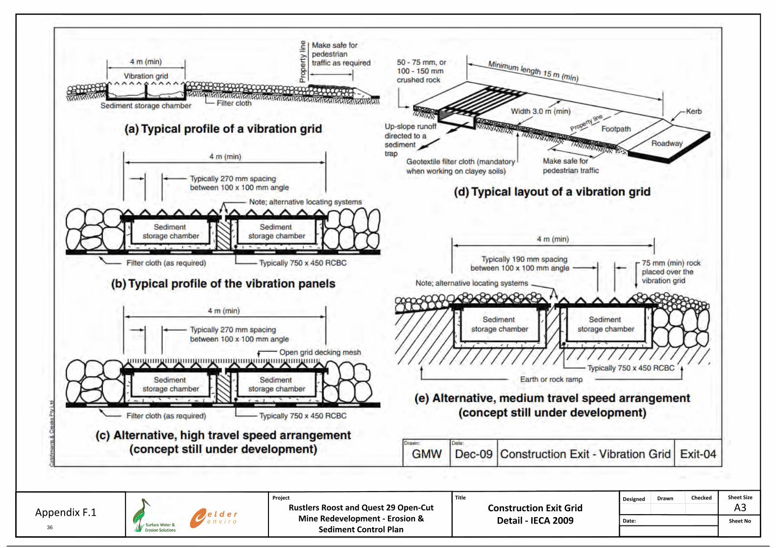
B
LEGEND: LEGEND:
A3Title
Construction Exit Grid Detail - IECA 2009
DrawnDesigned Checked Sheet Size
Sheet NoDate:
Project
Rustlers Roost and Quest 29 Open-Cut Mine Redevelopment - Erosion &
Sediment Control Plan
Appendix F.136

Appendix G.1 Collected soil samples and laboratory analysis
37

Table G.1 RR Sample locations and descriptions
Site: RR WRD 1
Easting (m), Northing (m):
770589 mE, 8570700 mN
Description:
Waste rock material on the southern area of the Rustler’s Roost WRD.
Emerson Class 8
22 June 2021
Site: RR WRD 2
Easting (m), Northing (m):
770458 mE, 8570832 mN
Description:
Waste rock material on the southwestern area of the Rustler’s Roost WRD.
Emerson Class 8
22 June 2021
Site: RR WRD 3
Easting (m), Northing (m):
770458 mE, 8571168 mN
Description:
As above
Emerson Class 8
22 June 2021
38
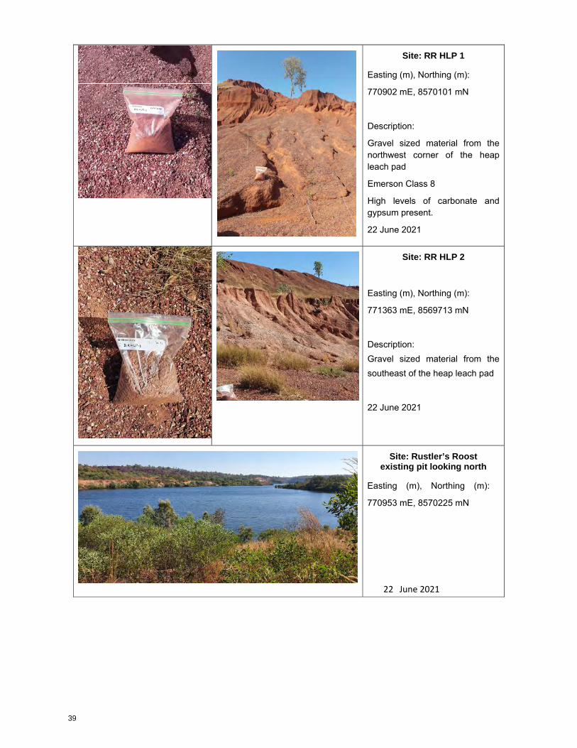
Site: RR HLP 1
Easting (m), Northing (m):
770902 mE, 8570101 mN
Description:
Gravel sized material from the northwest corner of the heap leach pad
Emerson Class 8
High levels of carbonate and gypsum present.
22 June 2021
Site: RR HLP 2
Easting (m), Northing (m):
771363 mE, 8569713 mN
Description: Gravel sized material from the southeast of the heap leach pad
22 June 2021
Site: Rustler’s Roost existing pit looking north
Easting (m), Northing (m):
770953 mE, 8570225 mN
22 June 2021
39

Table G.2 Q29 Sample locations and descriptions
Site: Q29 HLP 1 & 2
Easting (m), Northing (m):
779756 mE, 8568170 mN
Description:
Q29 Heap Leach pad. Looking across HLP toward sample location HLP
Emerson Class 8
22 June 2021
Site: Q29 HLP 3
Easting (m), Northing (m):
779755 mE, 8568187 mN
Description:
BHS Heal Leach Pad. Sample Q29 HLP 1 & 2 combined with Q29 HLP 3 for laboratory analysis
Emerson Class 8
22 June 2021
40

Site: Q29 Zamu WRD 3&4
Easting (m), Northing (m):
780759 mE, 8566164 mN
Description:
Current Zamu WRD. Samples combine for analysis
Emerson Class 5
22 June 2021
Site:Zamu Pit
Easting (m), Northing (m):
780715 mE, 8566317 mN
Description:
Current Zamu Pit Looking West.
22 June 2021
41

Envirolab Services Pty Ltd
ABN 37 112 535 645
12 Ashley St Chatswood NSW 2067
ph 02 9910 6200 fax 02 9910 6201
www.envirolab.com.au
CERTIFICATE OF ANALYSIS 272772
PO Box 36858, Winnellie, NT, 0821Address
Clare WhelanAttention
Douglas Partners NTClient
Client Details
29/06/2021Date completed instructions received
29/06/2021Date samples received
4 soilNumber of Samples
206279.00Your Reference
Sample Details
Results are reported on a dry weight basis for solids and on an as received basis for other matrices.
Samples were analysed as received from the client. Results relate specifically to the samples as received.
Please refer to the following pages for results, methodology summary and quality control data.
Analysis Details
Tests not covered by NATA are denoted with *Accredited for compliance with ISO/IEC 17025 - Testing.
NATA Accreditation Number 2901. This document shall not be reproduced except in full.
06/07/2021Date of Issue
06/07/2021Date results requested by
Report Details
Nancy Zhang, Laboratory Manager
Authorised By
Priya Samarawickrama, Senior Chemist
Giovanni Agosti, Group Technical Manager
Results Approved By
Revision No: R00
272772Envirolab Reference: Page | 1 of 8
42

Client Reference: 206279.00
0.20.22.00.2%Organic Matter (Combustion)
2102231022mg/kgEstimated Salinity*
616916µS/cmElectrical Conductivity 1:5 soil:water
9.45.88.35.5pH UnitspH 1:5 soil:water
01/07/202101/07/202101/07/202101/07/2021-Date analysed
01/07/202101/07/202101/07/202101/07/2021-Date prepared
soilsoilsoilsoilType of sample
RRHLPRRWDQ29 WD1Q29 WD2UNITSYour Reference
272772-4272772-3272772-2272772-1Our Reference
Misc Inorg - Soil
Envirolab Reference: 272772
R00Revision No:
Page | 2 of 8
43

Client Reference: 206279.00
19<17.0<1meq/100gCation Exchange Capacity
<0.1<0.10.18<0.1meq/100gExchangeable Na
0.120.360.150.29meq/100gExchangeable Mg
<0.1<0.1<0.1<0.1meq/100gExchangeable K
190.36.60.2meq/100gExchangeable Ca
02/07/202102/07/202102/07/202102/07/2021-Date analysed
02/07/202102/07/202102/07/202102/07/2021-Date prepared
soilsoilsoilsoilType of sample
RRHLPRRWDQ29 WD1Q29 WD2UNITSYour Reference
272772-4272772-3272772-2272772-1Our Reference
CEC
Envirolab Reference: 272772
R00Revision No:
Page | 3 of 8
44

Client Reference: 206279.00
Determination of exchangeable cations and cation exchange capacity in soils using 1M Ammonium Chloride exchange and ICP-AES analytical finish.
Metals-020
Dissolved or Total Carbon or Dissolved or Total Organic/Inorganic Carbon using the combustion method, high temperature catalytic combustion with NDIR.
Inorg-128
Soil samples are extracted and measured using a conductivity cell and dedicated meter.Inorg-034
Conductivity and Salinity - measured using a conductivity cell at 25°C in accordance with APHA latest edition 2510 and Rayment & Lyons.
Inorg-002
pH - Measured using pH meter and electrode in accordance with APHA latest edition, 4500-H+. Please note that the results for water analyses are indicative only, as analysis outside of the APHA storage times.
Inorg-001
Methodology SummaryMethod ID
Envirolab Reference: 272772
R00Revision No:
Page | 4 of 8
45

Client Reference: 206279.00
[NT]11800.20.21<0.1Inorg-1280.1%Organic Matter (Combustion)
[NT][NT][NT]221<5Inorg-0345mg/kgEstimated Salinity*
[NT]103[NT]61<1Inorg-0021µS/cmElectrical Conductivity 1:5 soil:water
[NT]100[NT]5.51[NT]Inorg-001pH UnitspH 1:5 soil:water
[NT]01/07/202101/07/202101/07/2021101/07/2021-Date analysed
[NT]01/07/202101/07/202101/07/2021101/07/2021-Date prepared
[NT]LCS-1RPDDup.Base#BlankMethodPQLUnitsTest Description
Spike Recovery %DuplicateQUALITY CONTROL: Misc Inorg - Soil
Envirolab Reference: 272772
R00Revision No:
Page | 5 of 8
46

Client Reference: 206279.00
[NT]83[NT][NT][NT][NT]<0.1Metals-0200.1meq/100gExchangeable Na
[NT]103[NT][NT][NT][NT]<0.1Metals-0200.1meq/100gExchangeable Mg
[NT]92[NT][NT][NT][NT]<0.1Metals-0200.1meq/100gExchangeable K
[NT]104[NT][NT][NT][NT]<0.1Metals-0200.1meq/100gExchangeable Ca
[NT]02/07/2021[NT][NT][NT][NT]02/07/2021-Date analysed
[NT]02/07/2021[NT][NT][NT][NT]02/07/2021-Date prepared
[NT]LCS-1RPDDup.Base#BlankMethodPQLUnitsTest Description
Spike Recovery %DuplicateQUALITY CONTROL: CEC
Envirolab Reference: 272772
R00Revision No:
Page | 6 of 8
47

Client Reference: 206279.00
Not ReportedNR
National Environmental Protection MeasureNEPM
Not specifiedNS
Laboratory Control SampleLCS
Relative Percent DifferenceRPD
Greater than>
Less than<
Practical Quantitation LimitPQL
Insufficient sample for this testINS
Test not requiredNA
Not testedNT
Result Definitions
Envirolab Reference: 272772
R00Revision No:
Page | 7 of 8
48

Client Reference: 206279.00
Guideline limits for Rinse Water Quality reported as per analytical requirements and specifications of AS 4187, Amdt 2 2019, Table7.2
The recommended maximums for analytes in urine are taken from “2018 TLVs and BEIs”, as published by ACGIH (where available).Limit provided for Nickel is a precautionary guideline as per Position Paper prepared by AIOH Exposure Standards Committee,2016.
Australian Drinking Water Guidelines recommend that Thermotolerant Coliform, Faecal Enterococci, & E.Coli levels are less than1cfu/100mL. The recommended maximums are taken from "Australian Drinking Water Guidelines", published by NHMRC & ARMC2011.
Surrogates are known additions to each sample, blank, matrix spike and LCS in a batch, of compounds whichare similar to the analyte of interest, however are not expected to be found in real samples.
Surrogate Spike
This comprises either a standard reference material or a control matrix (such as a blank sand or water) fortifiedwith analytes representative of the analyte class. It is simply a check sample.
LCS (LaboratoryControl Sample)
A portion of the sample is spiked with a known concentration of target analyte. The purpose of the matrix spikeis to monitor the performance of the analytical method used and to determine whether matrix interferencesexist.
Matrix Spike
This is the complete duplicate analysis of a sample from the process batch. If possible, the sample selectedshould be one where the analyte concentration is easily measurable.
Duplicate
This is the component of the analytical signal which is not derived from the sample but from reagents,glassware etc, can be determined by processing solvents and reagents in exactly the same manner as forsamples.
Blank
Quality Control Definitions
Samples for Microbiological analysis (not Amoeba forms) received outside of the 2-8°C temperature range do not meet the idealcooling conditions as stated in AS2031-2012.
Analysis of aqueous samples typically involves the extraction/digestion and/or analysis of the liquid phase only (i.e. NOT any settledsediment phase but inclusive of suspended particles if present), unless stipulated on the Envirolab COC and/or by correspondence.Notable exceptions include certain Physical Tests (pH/EC/BOD/COD/Apparent Colour etc.), Solids testing, total recoverable metalsand PFAS where solids are included by default.
Measurement Uncertainty estimates are available for most tests upon request.
Where sampling dates are not provided, Envirolab are not in a position to comment on the validity of the analysis whererecommended technical holding times may have been breached.
When samples are received where certain analytes are outside of recommended technical holding times (THTs), the analysis hasproceeded. Where analytes are on the verge of breaching THTs, every effort will be made to analyse within the THT or as soon aspracticable.
In circumstances where no duplicate and/or sample spike has been reported at 1 in 10 and/or 1 in 20 samples respectively, thesample volume submitted was insufficient in order to satisfy laboratory QA/QC protocols.
Matrix Spikes, LCS and Surrogate recoveries: Generally 70-130% for inorganics/metals (not SPOCAS); 60-140% fororganics/SPOCAS (+/-50% surrogates) and 10-140% for labile SVOCs (including labile surrogates), ultra trace organics andspeciated phenols is acceptable.
Duplicates: >10xPQL - RPD acceptance criteria will vary depending on the analytes and the analytical techniques but is typically inthe range 20%-50% – see ELN-P05 QA/QC tables for details; <10xPQL - RPD are higher as the results approach PQL and theestimated measurement uncertainty will statistically increase.
For VOCs in water samples, three vials are required for duplicate or spike analysis.
Spikes for Physical and Aggregate Tests are not applicable.
Filters, swabs, wipes, tubes and badges will not have duplicate data as the whole sample is generally extracted during sampleextraction.
Duplicate sample and matrix spike recoveries may not be reported on smaller jobs, however, were analysed at a frequency to meetor exceed NEPM requirements. All samples are tested in batches of 20. The duplicate sample RPD and matrix spike recoveries forthe batch were within the laboratory acceptance criteria.
Laboratory Acceptance Criteria
Envirolab Reference: 272772
R00Revision No:
Page | 8 of 8
49

50
51

52

53

Appendix H.1 Site Inspection Checklist - IECA 2008
54

Erosion and Sediment Control Site Inspection Checklist
IECA (Australasia) November 2008 Page 1
Site Inspection Checklist LOCATION OF DEVELOPMENT . . . . . . . . . . . . . . . . . . . . . . . . . . . . . . . . . . . . . . . .
. . . . . . . . . . . . . . . . . . . . . . . . . . . . . . . . . . . . . . . . . . . . . . . . . . . . . . . . . . . . . . . . . . . . . .
. . . . . . . . . . . . . . . . . . . . . . . . . . . . . . . . . . . . . . . . . . . . . . . . . . . . . . . . . . . . . . . . . . . . . .
INSPECTION OFFICER . . . . . . . . . . . . . . . . . . . . . . . . . . . DATE . . . . . . . . . . . . . . . . .
SIGNATURE . . . . . . . . . . . . . . . . . . . . . . . . . . . . . . . . . . . . . . . . . . . . . . . . . . . .
N/A – not applicable
– acceptable controls adopted
– measures are not acceptable, or a potential problem exists
Part A: Initial site inspection Item Consideration Assessment
1 Has an Erosion and Sediment Control Plan (ESCP) been approved for the site? . . . . . . . . . . .
2 Have all necessary development approvals been obtained? . . . . . . . . . . .
3 Are site conditions consistent with those assumed within the approved ESCP? . . . . . . . . . . .
4 Are environmental values being adequately protected? . . . . . . . . . . .
5 Are all ESC-related development conditions being satisfied? . . . . . . . . . . .
6 Was the full perimeter of the work site inspected? . . . . . . . . . . .
7 Are all reasonable and practicable measures being taken to minimise environmental harm? . . . . . . . . . . .
Part B: Site inspection and monitoring Item Consideration Assessment
8 Appropriate in-house site inspections of ESC practices are being carried out such that all control measures are being maintained. . . . . . . . . . . .
9 Site inspections and monitoring are being carried out at appropriate times and intervals. . . . . . . . . . . .

Erosion and Sediment Control Site Inspection Checklist
IECA (Australasia) November 2008 Page 2
Part C: Site establishment Item Consideration Assessment 10 Site access is controlled and the number of access points
minimised. . . . . . . . . . . . 11 Adequate drainage and sediment controls exist at site entry/exit
points. . . . . . . . . . . . 12 Adequate drainage, erosion and sediment controls have been
placed around the site compound. . . . . . . . . . . . 13 Office compound area and car park gravelled/stabilised where
necessary to control erosion and mud generation. . . . . . . . . . . . 14 Appropriate drainage and sediment controls are installed prior
to new areas being cleared or disturbed. . . . . . . . . . . .
Part D: Site and vegetation management Item Consideration Assessment 15 Vegetation Management Plan (VMP) and/or landscape plan
has been prepared. . . . . . . . . . . . 16 VMP and/or landscape plan is being appropriately
implemented. . . . . . . . . . . . 17 Site personnel appear to be aware of ESC requirements and
have ready access to the Erosion and Sediment Control Plan. . . . . . . . . . . . 18 ESC measures are being installed in accordance with the
approved Installation Sequence. . . . . . . . . . . . 19 Adequate supplies of ESC materials stored on-site: such as
straw bales, wire, stakes, sediment fence fabric, filter cloth, clean aggregate. . . . . . . . . . . .
20 Temporary access roads are stabilised where appropriate. . . . . . . . . . . .
21 Permanent roads are programmed to be sealed as soon as reasonable and practicable. . . . . . . . . . . .
22 Sediment deposition is not observed on external roads. . . . . . . . . . . .
23 Adequate records are being kept on chemical dosing of sediment basins, site inspections and site maintenance. . . . . . . . . . . .
24 The site is adequately prepared for the anticipated weather conditions. . . . . . . . . . . .
25 “Witness Points” and “Hold Points” are being appropriately managed and adhered to. . . . . . . . . . . .
26 Adequate protection provided for non-disturbance areas, buffer zones, protected trees. . . . . . . . . . . .
27 Disturbances removed from the drip line of protected trees. . . . . . . . . . . .
28 Brick-, masonry-, concrete-, and tile-cutting activities not carried out within road reserves (if possible) and all liquid waste is fully contained on-site or behind bunds. . . . . . . . . . . .

Erosion and Sediment Control Site Inspection Checklist
IECA (Australasia) November 2008 Page 3
Part E: Material and waste management Item Consideration Assessment 29 Chemicals and petroleum products appropriately stored on site.
. . . . . . . . . . . 30 Emergency spill response plan has been prepared for the site.
. . . . . . . . . . . 31 Oil/petroleum spill containment/response kits available on-site
where appropriate. . . . . . . . . . . . 32 Adequate litter and waste receptors exist on-site.
. . . . . . . . . . . 33 Waste receptors for concrete, paints, acid washing, litter and
building waste are being maintained. . . . . . . . . . . . 34 Cement-laden liquid waste and wash-off is prevented from
entering waterways and stormwater systems. . . . . . . . . . . . 35 Waste water from construction activities such as wash water,
de-watering operations, and dust control is being captured and treated. . . . . . . . . . . .
36 On-site mortar/cement/concrete mixing is carried out behind earth bunds, or other such measures employed to fully contain cement-laden waste and spills. . . . . . . . . . . .
37 Appropriate wash-down facilities provided from concrete trucks, mixing and pumping equipment. . . . . . . . . . . .
Part F: Soil management Item Consideration Assessment 38 Topsoil stripped and stockpiled prior to major earthworks.
. . . . . . . . . . . 39 Stockpiles located at least 5m away from top of watercourse
banks. . . . . . . . . . . . 40 Long-term soil stockpiles adequately protected against wind
and rain. . . . . . . . . . . . 41 Adequate sediment controls placed down-slope of stockpiles.
. . . . . . . . . . . 42 Stockpile sediment control (Filter Fence or Sediment Fence) is
appropriate for the soil type and site conditions. . . . . . . . . . . . 43 Adequate drainage controls placed up-slope of stockpiles.
. . . . . . . . . . . 44 Soil stockpiles do not encroach upon protected vegetation.
. . . . . . . . . . . 45 Subsoils adequately scarified prior to topsoil placement.
. . . . . . . . . . . 46 Topsoil is being replaced at an adequate depth.
. . . . . . . . . . .

Erosion and Sediment Control Site Inspection Checklist
IECA (Australasia) November 2008 Page 4
Part G: Drainage controls Item Consideration Assessment 47 Construction Drainage Plans (CDPs) are consistent with actual
site conditions (i.e. current stage of works). . . . . . . . . . . .
48 Drainage Control measures are consistent with the ESCP. . . . . . . . . . . .
49 Drainage Control measures are being adequately maintained in proper working order at all times.
. . . . . . . . . . .
50 Adequate diversion/management of up-slope stormwater. . . . . . . . . . . .
51 Up-slope “clean” water is being appropriately diverted around/through the site in a non-erosive manner.
. . . . . . . . . . .
52 Stormwater runoff diverted away from unstable slopes. . . . . . . . . . . .
53 Flow diversion channels/banks stabilised against erosion. . . . . . . . . . . .
54 Flow not unlawfully discharged onto an adjacent property. . . . . . . . . . . .
55 Spacing of cross drainage (e.g. Catch Drains or Flow Diversion Banks) down long slopes is sufficient to prevent “rill” erosion.
. . . . . . . . . . .
56 Earth batters are free of “rill” erosion. . . . . . . . . . . .
57 Catch Drains: (a) Adequate depth/width. (b) Adequate flow capacity is being maintained. (c) Stabilised against soil scour. (d) Clear of sediment deposition. (e) Appropriate grass length is being maintained. (f) Water discharges via a stable outlet.
. . . . . . . . . . . . . . . . . . . . . . . . . . . . . . . . . . . . . . . . . . . . . . . . . . . . . . . . . . . . . . . . . .
58 Channel Linings (mats): (a) Lining is well anchored. (b) Mats overlap in direction of flow. (c) Lining is appropriate for flow conditions. (d) No damage to the mat by lateral inflows.
. . . . . . . . . . . . . . . . . . . . . . . . . . . . . . . . . . . . . . . . . . . .
59 Check Dams: (a) Flow is passing over the dams and not around them. (b) Check Dams are not causing excessive channel restriction. (c) Rock Check Dams are not used in shallow drains. (d) Check Dams are appropriately spaced down the drain.
. . . . . . . . . . . . . . . . . . . . . . . . . . . . . . . . . . . . . . . . . . . .
60 Chutes (rock): (a) Geotextile filter cloth is installed under the rock. (b) Rock placement has not reduced chute flow capacity. (c) Rock size appears adequate for expected flow velocity. (d) Water discharges via a stable outlet.
. . . . . . . . . . . . . . . . . . . . . . . . . . . . . . . . . . . . . . . . . . . .

Erosion and Sediment Control Site Inspection Checklist
IECA (Australasia) November 2008 Page 5
61 Chutes (geotextile): (a) Lining is well anchored.(b) Mats overlap in direction of flow.(c) Lining is appropriate for flow conditions.(d) Water discharges through a stable outlet.
. . . . . . . . . . .
. . . . . . . . . . .
. . . . . . . . . . .
. . . . . . . . . . . 62 Level Spreaders:
(a) Outlet weir is level and undamaged.(b) No sediment deposition within Level Spreader.(c) Discharges “sheet” flow to a stable, well-grassed outlet.
. . . . . . . . . . .
. . . . . . . . . . .
. . . . . . . . . . . 63 Slope Drains:
(a) Adequate erosion/sediment controls at pipe inlet.(b) Pipes are well anchored.(c) No obvious water leaks.(d) Water discharges via a stable outlet.
. . . . . . . . . . .
. . . . . . . . . . .
. . . . . . . . . . .
. . . . . . . . . . . 64 Stormwater Outlets:
(a) Energy dissipation is appropriate for the conditions.(b) Rock size is greater than 200mm.(c) Soil erosion is being controlled.
. . . . . . . . . . .
. . . . . . . . . . .
. . . . . . . . . . . 65 Temporary Watercourse Crossings:
(a) Crossing type is appropriate for the stream conditions.(b) Sediment runoff from the approach roads is controlled.(c) Likely damage to the crossing and the stream caused by
possible overtopping flows is considered acceptable.
. . . . . . . . . . .
. . . . . . . . . . .
. . . . . . . . . . .

Erosion and Sediment Control Site Inspection Checklist
IECA (Australasia) November 2008 Page 6
Part H: Erosion controls Item Consideration Assessment 66 Erosion control standard is consistent with requirements of
regulatory authority. . . . . . . . . . . . 67 Soil erosion is being controlled to a standard consistent with the
level of environmental risk. . . . . . . . . . . . 68 Erosion Control measures are consistent with the approved
ESCP. . . . . . . . . . . . 69 Disturbance to existing ground cover is being delayed as long
as possible. . . . . . . . . . . . 70 Raindrop impact erosion is being adequately controlled.
. . . . . . . . . . . 71 Earth batters are free of “rill” erosion.
. . . . . . . . . . . 72 Dust problems are being adequately controlled.
. . . . . . . . . . . 73 Erosion Control measures are being adequately maintained in
proper working order at all times. . . . . . . . . . . . 74 All disturbed areas are adequately stabilised given:
(a) Erosion hazard risk.(b) Degree of downstream sediment control.(c) Days since earthworks were finalised.(d) Days before any soil disturbance will be re-worked.
. . . . . . . . . . .
. . . . . . . . . . .
. . . . . . . . . . .
. . . . . . . . . . . 75 Erosion Control Blankets:
(a) Blankets are well anchored.(b) Blankets overlap in direction of stormwater flow.(c) Blanket strength is appropriate for site conditions.(d) Synthetic blanket reinforcing will not endanger wildlife.(e) Blankets not damaged by lateral inflows.(f) Blankets protected against movement by winds.
. . . . . . . . . . .
. . . . . . . . . . .
. . . . . . . . . . .
. . . . . . . . . . .
. . . . . . . . . . .
. . . . . . . . . . . 76 Mulching (light):
(a) Minimum 70% coverage of soil surface.(b) Suitable tackifier used on steep slopes.(c) Drainage controls preventing mulch displacement.
. . . . . . . . . . .
. . . . . . . . . . .
. . . . . . . . . . . 77 Mulch (heavy):
(a) Minimum 100% coverage of soil.(b) Minimum depth adequate to control weeds.(c) Drainage controls preventing mulch displacement.
. . . . . . . . . . .
. . . . . . . . . . .
. . . . . . . . . . . 78 Soil Binders:
(a) No adverse environmental impacts observed.(b) No obvious over-spray.(c) Soil binders applied during appropriate weather conditions.
. . . . . . . . . . .
. . . . . . . . . . .
. . . . . . . . . . .
Erosion and Sediment Control Site Inspection Checklist
IECA (Australasia) November 2008 Page 7
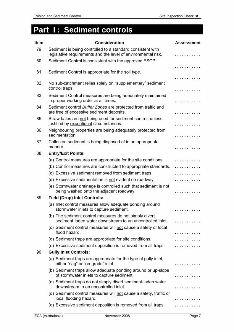
Part I: Sediment controls Item Consideration Assessment 79 Sediment is being controlled to a standard consistent with
legislative requirements and the level of environmental risk. . . . . . . . . . . .
80 Sediment Control is consistent with the approved ESCP. . . . . . . . . . . .
81 Sediment Control is appropriate for the soil type. . . . . . . . . . . .
82 No sub-catchment relies solely on “supplementary” sediment control traps.
. . . . . . . . . . .
83 Sediment Control measures are being adequately maintained in proper working order at all times.
. . . . . . . . . . .
84 Sediment control Buffer Zones are protected from traffic and are free of excessive sediment deposits.
. . . . . . . . . . .
85 Straw bales are not being used for sediment control, unless justified by exceptional circumstances.
. . . . . . . . . . .
86 Neighbouring properties are being adequately protected from sedimentation.
. . . . . . . . . . .
87 Collected sediment is being disposed of in an appropriate manner.
. . . . . . . . . . .
88 Entry/Exit Points: (a) Control measures are appropriate for the site conditions. (b) Control measures are constructed to appropriate standards. (c) Excessive sediment removed from sediment traps. (d) Excessive sedimentation is not evident on roadway. (e) Stormwater drainage is controlled such that sediment is not
being washed onto the adjacent roadway.
. . . . . . . . . . . . . . . . . . . . . . . . . . . . . . . . . . . . . . . . . . . . . . . . . . . . . . .
89 Field (Drop) Inlet Controls: (a) Inlet control measures allow adequate ponding around
stormwater inlets to capture sediment. (b) The sediment control measures do not simply divert
sediment-laden water downstream to an uncontrolled inlet. (c) Sediment control measures will not cause a safety or local
flood hazard. (d) Sediment traps are appropriate for site conditions. (e) Excessive sediment deposition is removed from all traps.
. . . . . . . . . . . . . . . . . . . . . . . . . . . . . . . . . . . . . . . . . . . . . . . . . . . . . . .
90 Gully Inlet Controls: (a) Sediment traps are appropriate for the type of gully inlet,
either “sag” or “on-grade” inlet. (b) Sediment traps allow adequate ponding around or up-slope
of stormwater inlets to capture sediment. (c) Sediment traps do not simply divert sediment-laden water
downstream to an uncontrolled inlet. (d) Sediment control measures will not cause a safety, traffic or
local flooding hazard. (e) Excessive sediment deposition is removed from all traps.
. . . . . . . . . . . . . . . . . . . . . . . . . . . . . . . . . . . . . . . . . . . . . . . . . . . . . . .

Erosion and Sediment Control Site Inspection Checklist
IECA (Australasia) November 2008 Page 8
91 Table drain sediment traps: (a) Choice of sediment trap is appropriate for flow conditions. (b) Excessive sediment is removed from all traps. (c) Spill-through weir is set to an appropriate elevation. (d) Spill-through weir has adequate width. (e) Sediment Fence traps are formed in a tight U-shape that
adequately prevents water bypassing the traps.
. . . . . . . . . . . . . . . . . . . . . . . . . . . . . . . . . . . . . . . . . . . . . . . . . . . . . . .
92 Sediment Fences: (a) Choice of fabric is appropriate. (b) Bottom of fabric is securely buried. (c) Fabric is appropriately overlapped at joints. (d) Fabric is appropriately attached to posts. (e) Support posts are at correct spacing (2m or 3m with backing). (f) Sediment Fence does not cause flow diversion/bypass. (g) Sediment Fence has regular returns. (h) Lower end(s) of fence is/are returned up the slope. (i) Sediment Fences are free of damage. (j) All fences are free of excessive sediment deposition. (k) Fences are adequately spaced from toe of fill banks.
. . . . . . . . . . . . . . . . . . . . . . . . . . . . . . . . . . . . . . . . . . . . . . . . . . . . . . . . . . . . . . . . . . . . . . . . . . . . . . . . . . . . . . . . . . . . . . . . . . . . . . . . . . . . . . . . . . . . . . . . .
93 Filter Tube Sediment Traps: (a) Geometry and layout match design details. (b) Sediment-laden water cannot bypass the filtration system. (c) Filter Tubes do not need replacement. (d) Filter Tubes and embankment are free of damage.
. . . . . . . . . . . . . . . . . . . . . . . . . . . . . . . . . . . . . . . . . . . .
94 Rock Filter Dams (Sediment Traps): (a) Geometry and layout match design details. (b) Excessive sediment removed from up-slope of all traps. (c) The filtration system is free from sediment blockage. (d) Rock Filter Dam and spillway are free of damage.
. . . . . . . . . . . . . . . . . . . . . . . . . . . . . . . . . . . . . . . . . . . .
95 Sediment Weirs: (a) Geometry and layout match design details. (b) Excessive sediment removed from up-slope of all traps. (c) The filtration system is free from sediment blockage. (d) Sediment Weir and splash pad (if any) are free of damage.
. . . . . . . . . . . . . . . . . . . . . . . . . . . . . . . . . . . . . . . . . . . .
96 Sediment Trench: (a) Trench geometry and layout match design details. (b) Excessive sediment removed from the trench. (c) Outlet structure (if any) is free from sediment blockage. (d) The open trench does not represent a safety hazard.
. . . . . . . . . . . . . . . . . . . . . . . . . . . . . . . . . . . . . . . . . . . .
97 Sediment Controls for Non-Storm Runoff (a) Choice of sediment trap is appropriate for the site
conditions and level of environmental risk. (b) All sediment is being contained within trap.
. . . . . . . . . . . . . . . . . . . . . .

Erosion and Sediment Control Site Inspection Checklist
IECA (Australasia) November 2008 Page 9
98 Sediment Basin (1): Location . . . . . . . . . . . . . . . . . . . . . . . . . (a) Basin geometry and layout match design details.(b) “As constructed” plans have been prepared.(c) The basin does not represent a safety risk.(d) De-watering is conducted in accordance with best practice.(e) Excessive sediment removed from basin.(f) Sediment depth marker is installed and maintained.(g) Primary outlet structure is free from sediment blockage.(h) Flow conditions are not compromised across the spillway.(i) Emergency spillway has adequate scour control.(j) Adequate quantities of flocculant (if required) exist on-site.(k) Soil erosion is adequately controlled at inlet points.(l) The settled sediment layer is clearly visible through ponded
water prior to discharge such water.
. . . . . . . . . . .
. . . . . . . . . . .
. . . . . . . . . . .
. . . . . . . . . . .
. . . . . . . . . . .
. . . . . . . . . . .
. . . . . . . . . . .
. . . . . . . . . . .
. . . . . . . . . . .
. . . . . . . . . . .
. . . . . . . . . . .
. . . . . . . . . . . 99
Sediment Basin (2): Location . . . . . . . . . . . . . . . . . . . . . . . . . (a) Basin geometry and layout match design details.(b) “As constructed” plans have been prepared.(c) The basin does not represent a safety risk.(d) De-watering is conducted in accordance with best practice.(e) Excessive sediment removed from basin.(f) Sediment depth marker is installed and maintained.(g) Primary outlet structure is free from sediment blockage.(h) Flow conditions are not compromised across the spillway.(i) Emergency spillway has adequate scour control.(j) Adequate quantities of flocculant (if required) exist on-site.(k) Soil erosion is adequately controlled at inlet points.(l) The settled sediment layer is clearly visible through ponded
water prior to discharge such water.
. . . . . . . . . . .
. . . . . . . . . . .
. . . . . . . . . . .
. . . . . . . . . . .
. . . . . . . . . . .
. . . . . . . . . . .
. . . . . . . . . . .
. . . . . . . . . . .
. . . . . . . . . . .
. . . . . . . . . . .
. . . . . . . . . . .
. . . . . . . . . . . 100
Sediment Basin (3): Location . . . . . . . . . . . . . . . . . . . . . . . . . (a) Basin geometry and layout match design details.(b) “As constructed” plans have been prepared.(c) The basin does not represent a safety risk.(d) De-watering is conducted in accordance with best practice.(e) Excessive sediment removed from basin.(f) Sediment depth marker is installed and maintained.(g) Primary outlet structure is free from sediment blockage.(h) Flow conditions are not compromised across the spillway.(i) Emergency spillway has adequate scour control.(j) Adequate quantities of flocculant (if required) exist on-site.(k) Soil erosion is adequately controlled at inlet points.(l) The settled sediment layer is clearly visible through ponded
water prior to discharge such water.
. . . . . . . . . . .
. . . . . . . . . . .
. . . . . . . . . . .
. . . . . . . . . . .
. . . . . . . . . . .
. . . . . . . . . . .
. . . . . . . . . . .
. . . . . . . . . . .
. . . . . . . . . . .
. . . . . . . . . . .
. . . . . . . . . . .
. . . . . . . . . . .

Erosion and Sediment Control Site Inspection Checklist
IECA (Australasia) November 2008 Page 10
101 Other Sediment Trap (1): Type . . . . . . . . . . . . . . . . . . . . . . . . (a) Choice of sediment trap is appropriate for the site
conditions and level of environmental risk.(b) The sediment trap allows adequate ponding to capture
coarse sediment (Type 2 and Type 3 Sediment Traps).(c) The sediment trap allows adequate filtration to capture fine
sediment (Type 2 Sediment Traps).(d) The sediment trap does not simply divert sediment-laden
water downstream to an uncontrolled outlet.(e) The sediment trap does not cause a safety, traffic or local
flood hazard.(f) Excessive sediment deposition is removed from all traps.
. . . . . . . . . . .
. . . . . . . . . . .
. . . . . . . . . . .
. . . . . . . . . . .
. . . . . . . . . . .
. . . . . . . . . . . 102 Other Sediment Trap (2): Type . . . . . . . . . . . . . . . . . . . . . . . .
(a) Choice of sediment trap is appropriate for the siteconditions and level of environmental risk.
(b) The sediment trap allows adequate ponding to capturecoarse sediment (Type 2 and Type 3 Sediment Traps).
(c) The sediment trap allows adequate filtration to capture finesediment (Type 2 Sediment Traps).
(d) The sediment trap does not simply divert sediment-ladenwater downstream to an uncontrolled outlet.
(e) The sediment trap does not cause a safety, traffic or localflood hazard.
(f) Excessive sediment deposition is removed from all traps.
. . . . . . . . . . .
. . . . . . . . . . .
. . . . . . . . . . .
. . . . . . . . . . .
. . . . . . . . . . .
. . . . . . . . . . . 103 Other Sediment Trap (3): Type . . . . . . . . . . . . . . . . . . . . . . . .
(a) Choice of sediment trap is appropriate for the siteconditions and level of environmental risk.
(b) The sediment trap allows adequate ponding to capturecoarse sediment (Type 2 and Type 3 Sediment Traps).
(c) The sediment trap allows adequate filtration to capture finesediment (Type 2 Sediment Traps).
(d) The sediment trap does not simply divert sediment-ladenwater downstream to an uncontrolled outlet.
(e) The sediment trap does not cause a safety, traffic or localflood hazard.
(f) Excessive sediment deposition is removed from all traps.
. . . . . . . . . . .
. . . . . . . . . . .
. . . . . . . . . . .
. . . . . . . . . . .
. . . . . . . . . . .
. . . . . . . . . . . 104 Other Sediment Trap (4): Type . . . . . . . . . . . . . . . . . . . . . . . .
(a) Choice of sediment trap is appropriate for the siteconditions and level of environmental risk.
(b) The sediment trap allows adequate ponding to capturecoarse sediment (Type 2 and Type 3 Sediment Traps).
(c) The sediment trap allows adequate filtration to capture finesediment (Type 2 Sediment Traps).
(d) The sediment trap does not simply divert sediment-ladenwater downstream to an uncontrolled outlet.
(e) The sediment trap does not cause a safety, traffic or localflood hazard.
(f) Excessive sediment deposition is removed from all traps.
. . . . . . . . . . .
. . . . . . . . . . .
. . . . . . . . . . .
. . . . . . . . . . .
. . . . . . . . . . .
. . . . . . . . . . .

Erosion and Sediment Control Site Inspection Checklist
IECA (Australasia) November 2008 Page 11
Part J: Instream works Item Consideration Assessment 105 All necessary State and local government approvals have been
obtained. . . . . . . . . . . . 106 Temporary Watercourse Crossings (e.g. construction access)
have been reduced to the minimum practical number. . . . . . . . . . . . 107 Instream disturbance is limited to the minimum necessary to
complete the proposed works. . . . . . . . . . . . 108 Timing and staging of instream works will minimise exposure of
the site to storm and/or stream flows. . . . . . . . . . . . 109 Instream works are occurring at a time of the year that will
minimise overall potential environmental harm: (a) avoiding seasonal high flows;(b) avoiding periods of likely fish migration;(c) avoiding active bird migration periods (Ramsar wetlands).
. . . . . . . . . . .
. . . . . . . . . . .
. . . . . . . . . . . 110 Instream structures are not located on, or adjacent to, unstable
or highly mobile channel bends. . . . . . . . . . . . 111 Construction works are not unnecessarily disturbing instream or
riparian vegetation. . . . . . . . . . . . 112 Overbank disturbances are limited to only one bank wherever
reasonable and practicable. . . . . . . . . . . . 113 Stormwater runoff moving towards the channel from adjacent
areas is being appropriately diverted around soil disturbances. . . . . . . . . . . . 114 Erosion is not occurring as a result of stormwater passing down
channel banks. . . . . . . . . . . . 115 Normal channel flows are being diverted around in-bank
disturbances as appropriate for the expected weather and channel flow conditions. . . . . . . . . . . .
116 Appropriate temporary erosion control measures are being applied to disturbed areas. . . . . . . . . . . .
117 Synthetic reinforced erosion control blankets/mats are not being used where there is a potential threat to wildlife. . . . . . . . . . . .
118 Adopted instream sediment control measures are appropriate for the expected site and channel conditions. . . . . . . . . . . .
119 Sediment Fences have not been placed in areas of actual or potential concentrated flow. . . . . . . . . . . .
120 Appropriate material (spoil) de-watering procedures have been adopted. . . . . . . . . . . .
121 Site stabilisation and rehabilitation is occurring as soon as practicable. . . . . . . . . . . .
122 Appropriate site rehabilitation measures are being adopted. . . . . . . . . . . .
Erosion and Sediment Control Site Inspection Checklist
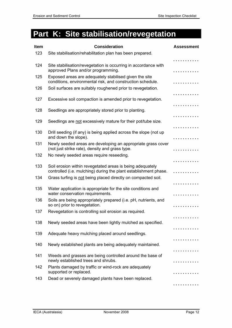
IECA (Australasia) November 2008 Page 12
Part K: Site stabilisation/revegetation Item Consideration Assessment 123 Site stabilisation/rehabilitation plan has been prepared.
. . . . . . . . . . . 124 Site stabilisation/revegetation is occurring in accordance with
approved Plans and/or programming. . . . . . . . . . . . 125 Exposed areas are adequately stabilised given the site
conditions, environmental risk, and construction schedule. . . . . . . . . . . . 126 Soil surfaces are suitably roughened prior to revegetation.
. . . . . . . . . . . 127 Excessive soil compaction is amended prior to revegetation.
. . . . . . . . . . . 128 Seedlings are appropriately stored prior to planting.
. . . . . . . . . . . 129 Seedlings are not excessively mature for their pot/tube size.
. . . . . . . . . . . 130 Drill seeding (if any) is being applied across the slope (not up
and down the slope). . . . . . . . . . . . 131 Newly seeded areas are developing an appropriate grass cover
(not just strike rate), density and grass type. . . . . . . . . . . . 132 No newly seeded areas require reseeding.
. . . . . . . . . . . 133 Soil erosion within revegetated areas is being adequately
controlled (i.e. mulching) during the plant establishment phase. . . . . . . . . . . . 134 Grass turfing is not being placed directly on compacted soil.
. . . . . . . . . . . 135 Water application is appropriate for the site conditions and
water conservation requirements. . . . . . . . . . . . 136 Soils are being appropriately prepared (i.e. pH, nutrients, and
so on) prior to revegetation. . . . . . . . . . . . 137 Revegetation is controlling soil erosion as required.
. . . . . . . . . . . 138 Newly seeded areas have been lightly mulched as specified.
. . . . . . . . . . . 139 Adequate heavy mulching placed around seedlings.
. . . . . . . . . . . 140 Newly established plants are being adequately maintained.
. . . . . . . . . . . 141 Weeds and grasses are being controlled around the base of
newly established trees and shrubs. . . . . . . . . . . . 142 Plants damaged by traffic or wind-rock are adequately
supported or replaced. . . . . . . . . . . . 143 Dead or severely damaged plants have been replaced.
. . . . . . . . . . .

Erosion and Sediment Control Site Inspection Checklist
IECA (Australasia) November 2008 Page 13
Part L: Action summary Item Consideration Yes or No
Answer “Yes” if further action is required on site 144 Do any existing control measures require modification?
. . . . . . . . . . . 145 Are additional ESC measures required on the site?
. . . . . . . . . . . 146 Are alternative ESC measures required on the site?
. . . . . . . . . . . 147 Is a revised ESCP required for the site?
. . . . . . . . . . . 148 Is further water quality monitoring required?
. . . . . . . . . . . 149 Do any ESC measures need repairs or de-silting?
. . . . . . . . . . . 150 Is additional erosion control (minimum 70% cover) required?
. . . . . . . . . . . 151 Will the underlying cause of any non-compliance need further
investigation? . . . . . . . . . . . 152 Will it be necessary for the site to adopt an alternative Code of
Practice better suited to the site conditions or work activities? . . . . . . . . . . . 153 Will further site inspections be required?
. . . . . . . . . . .
Notes: . . . . . . . . . . . . . . . . . . . . . . . . . . . . . . . . . . . . . . . . . . . . . . . . . . . . . . . . . . . . . . . . . . . . . .
. . . . . . . . . . . . . . . . . . . . . . . . . . . . . . . . . . . . . . . . . . . . . . . . . . . . . . . . . . . . . . . . . . . . . .
. . . . . . . . . . . . . . . . . . . . . . . . . . . . . . . . . . . . . . . . . . . . . . . . . . . . . . . . . . . . . . . . . . . . . .
. . . . . . . . . . . . . . . . . . . . . . . . . . . . . . . . . . . . . . . . . . . . . . . . . . . . . . . . . . . . . . . . . . . . . .
. . . . . . . . . . . . . . . . . . . . . . . . . . . . . . . . . . . . . . . . . . . . . . . . . . . . . . . . . . . . . . . . . . . . . .
. . . . . . . . . . . . . . . . . . . . . . . . . . . . . . . . . . . . . . . . . . . . . . . . . . . . . . . . . . . . . . . . . . . . . .
. . . . . . . . . . . . . . . . . . . . . . . . . . . . . . . . . . . . . . . . . . . . . . . . . . . . . . . . . . . . . . . . . . . . . .
. . . . . . . . . . . . . . . . . . . . . . . . . . . . . . . . . . . . . . . . . . . . . . . . . . . . . . . . . . . . . . . . . . . . . .
. . . . . . . . . . . . . . . . . . . . . . . . . . . . . . . . . . . . . . . . . . . . . . . . . . . . . . . . . . . . . . . . . . . . . .
. . . . . . . . . . . . . . . . . . . . . . . . . . . . . . . . . . . . . . . . . . . . . . . . . . . . . . . . . . . . . . . . . . . . . .
. . . . . . . . . . . . . . . . . . . . . . . . . . . . . . . . . . . . . . . . . . . . . . . . . . . . . . . . . . . . . . . . . . . . . .