report midterm - weebly
TRANSCRIPT

Micro - Hydro Power
Water Tower Generator
Members:
Darius Wright - Tippins: Project Manager
Komlan Amesse: Lead EE
Moise Zamor: Lead CE/ Webmaster
Olivier Perrault: Financial Manager
Midterm
Report
II
Team
5
Sponsor: Talquin
Electric Cooperative
Faculty Advisor/s
Dr. Hui Li
Instructor/s
Dr. Jerris Hooker
Submitted 12/05/2016

Table of Contents
Table of Figures*
Table of Tables*
ACKNOWLEDGMENTS
Introduction
Background and Literature Review
History of renewable energy
Hydro Electric Power
Needs Statements
Objectives:
Constraints
Schedule
Design and Analysis
Solar Panels
PV module (photovoltaic) system
PV system Components for small scale
Advantages of PV
Disadvantages of PV
Microcontroller Unit
Hydro-system
Turbines
Battery
Results
Small Scale
Potential Challenges
Future plans
Risk Assessment Summary
Conclusion
References
*Biography

Table of Figures*
Figure: 1 Design Project Diagram…………………………………………...……………………8
Figure: 2 Flowchart for the Design Project……………………………………………….…….11
Figure: 3 Gantt chart…………………………………………………………………….………13
Figure: 4 Sample of PV in parallel en series……………………………………………….……14
Figure: 5 Different type of tracker……………………………………………………………….15
Figure: 6 Flowchart of the Microcontroller Unit………………………………………………...16
Figure: 7 Water flow system…………………………………………………………………….17
Figure: 8 Graph showing monthly peak load………………...…………………………...……...19
Figure: 9 Graph showing monthly kWh used…………………...…………………………...….19
Figure: 10 Graph showing monthly electricity bill……………....…………….…….………......19
Figure: 11 Data showing hourly level of water in tower...……...……………………………….19
Figure: 12 Operative ranges of different turbines…………….………………………………….23
Figure: 13 Power Spout turbine………………………………………………………………….25
Figure: 14 Zurn Industries turbine…………………………………………………………….…25
Figure: 15 Water Buddy turbine…………………………………………………………………26

Table of Tables*
Table 1: Contrast between different types of PV module……………………….... 13
Table 2: Bradfordville monthly power used/billing…….……………………….... 19
Table 3: Lead Acid vs. LiFePO4………....………………………………………...26
Table 4: Result table………………………………………………………………...27

ABSTRACT
For this project, Sponsored by Talquin Electric Cooperative, the team is developing a hybrid
water tower energy storage system which will harness the unused energy from water towers,
reducing the cost of storing water and supplying members. Talquin is investing in renewable
resources and in need of a system to convert unused potential/kinetic energy to electrical energy
from their water storage towers. Talquin is currently harnessing 0Wh of energy. The team has a
48V DC 220w solar panel which will be used to power a DC pump. The pump will drive the
water into the tower until specific level is reached. As water fall, the kinetic energy will convert
into electrical power. The electrical power will be stored into the battery bank, then used to
power the DC water pump and excess power can be connected to the grid. The CPU will be the
heart of the project, acting as a relay the CPU, depending on the water levels will turn the pump
on and off.
To ensure success of this project, research is currently being conducted to obtain sufficient
knowledge of the needs of water towers as well as efficient pumps, turbine and batteries. Once
confident in our research the team will move forward onto calculations, coding for the CPU, as
well as building the system. After numerous test, the team will see if the system can harness a
percentage of the incoming power used to start the process.

ACKNOWLEDGMENTS
On the behalf of Team 5, we would like to give thanks to the FAMU-FSU College Of
Engineering for giving us the opportunity to participate on this project for the 2016-2017 Senior
Design school year. .
We would like to give thanks to our sponsor, Talquin Electric Cooperative for trusting us with
making your project come true.
Special Thanks to Dr. Li and Dr. Hooker for supervision and providing guidance and direction
with our project.
Special Thanks to Lucid Energy
1. Introduction
Excessive energies are used frequently each day to pump water to the water tower to serve the
customer. A body of water at relatively high elevation represents a potential energy. At the need,
the water stored in the tower is release through the pipe for distribution. The goal of this project
is to recover some if not all the potential energy and transform it into electrical energy. To offset
the maximum of electrical energy used to pump the water to the tower, solar system and turbine
generator constitutes two major components of the project. The system can be call “Micro
Hybrid hydro-solar system” and the overall system is assisted by the grid as backup. The aim of
this project is to design a simple, less expensive and which reduces the cost pumping and
distributing water to the customer since the electricity used to pump water into the tower requires
substantial expenses. At the normal scale the water tower represent a huge energy storage. For
small scale of the design a container of 5 to 50 gallons (US) is use as water reservoir
For many years now Talquin has been using their water towers to store and create reliable fresh
water to their members, whether there is an outage or power surge within the communities. The
purpose of a water tower is to provide water storage pressure for surrounding areas and back up
capacity in case of a fire demand. The tower is an elevated structure which can create maximum
amount of pressure to distribute potable water to its community. A water tower acts as a
reservoir to help the community with water needs during peak usage hours. Talquin goal is, and
always has been, to provide you a safe and dependable supply of drinking water. To continue
providing fresh water to the communities at a low cost, Talquin is looking to enhance their water
tower system.
A few utilities are experimenting with using water turbines in their water storage towers to store
energy. By the definition, there is Potential energy in the mass body of water being stored at
about 150 to 200 feet high. As the water is released from the tower and into the pipeline, kinetic
energy is created. The purpose of this project is to design a system that can turn both the kinetic
and potential energy created by the down flow of water into electrical power. This can be done
by implementing a water turbine into the down flow system which then will transfer the kinetic
energy into electrical power. The electrical power will be stored into batteries to be returned into
the system. This process will help reduce the total cost of electricity need to pump water up the

system. A small-scale model of this type system will be built to properly demonstrate the
process.
Figure: 1 Design Project Diagram
2. Background and Literature Review
2.1 History of renewable energy Fossil fuels have been a primary source of energy since coal was discovered. When
inventors found various ways, coal could be used as a source of energy it fueled the industrial
revolution in the western hemisphere. This then began the race to build bigger, and faster
machines once the coal burning steam engine was built as these were the same machines that
provided transportation and replaced work done by animals and humans. The invention of the
internal combustion engine came into play which used oil and gas instead of coal, making it
more efficient, but the pure number of automobiles on the road alone has offset the positive
impacts set from this transition. Burning all these fossil fuels has steadily released harmful gases
that have grown to be the problem they are today. At the rate of the greenhouse gases like carbon
dioxide released in the air scientist predict that “we will destroy both the breathable air and the
energy reserves of our only home.”[1]. The growing environmental problems these sources have
played has been a worry to world leaders since the end of the 20th century and even greater since

the beginning of the 21st century. Along with the high levels of pollution fossil fuels cause,
source limitation has been another reason scientist have looked to other sources of energy.
It is for this reason that although an abundance of the energy is still produced in the
United States is from fossil-fuel and nuclear power plants, the shift from this old way of energy
has been quick but steadily replaced by renewable energy. Renewable energy unlike fossil fuels
can be replaced at a faster rate and is a source of energy that does not need to worry about being
limited because of its abundance. Wind, water, and solar are all examples of renewable sources
of energy that are natural and can be harnessed to replace the power fossil fuels use to provide.
The transition to this form of energy steadily growing can be proven by statistics as a report from
the International Energy Agency showed an increase of renewable sourced electricity from “over
13% in 2012 to 22% the following year and a projected 26% by 2020.” [3] This push is due to
renewable energy not only them being practically nonpolluting but also more cost effective for
producers and consumers.
2.1.1 Hydro Electric Power
The embrace of renewable energy is happening on a large scale and hydropower leads the
way of them all as the most important and widely used renewable energy source. It plays a vital
role in the supply of electricity today contributing “more than 16% of electricity worldwide and
about 85% of global renewable electricity.” Falling water itself is an energy source that has been
used since the first major plant took advantage of the abundance of kinetic energy created by
Niagara Falls in 1895. How it works is by using the force of the falling water to transform
mechanical energy striking the blades of the turbine. The rotation of the turbine in-turn rotates
electromagnets, generating a current in coils of wire. This current is then placed through a
transformer where the voltage is stepped up to travel long distance over power lies. The benefits
of using this type of technology range from low operation and maintenance costs to minimal
pollution as a result from its energy production making it a high desire as a renewable energy
source. To achieve the goal of this project, the same concept of hydroelectric will be apply to
harness the electricity since most hydroelectric power comes from the potential energy of water
driving a water turbine and generator. The first diagram of the project includes batteries Bank.
But after deep analysis, we decide to implement batteryless on-grid systems which use the grid

as the “dump load,” sending excess energy back to the utility’s grid to be credited to Talquin
Company for use at other time. Below is the diagram of the project.
Figure: 2 Flowchart for the Design Project
2.1.2 Needs Statements
The Senior design project for water tower is sponsored by Talquin. The system presently utilized
by the company to pump water up and down in the tower use only electrical current from the grid
and as result increase their utilities cost. Furthermore, Talquin realize a waste of a massive
amount of potential and kinetic energy that can be utilize as electrical power.
“Talquins’s current water system provide no energy and cost saving”
2.1.3 Goal Statement and Objective
“Design a more independent and efficient system which convert potential and kinetic energy
to electrical energy and provides electrical power back to the system”

Objectives:
● Successfully convert potential and kinetic energy to electrical energy
● Successfully harness power generated by the turbine and send it to the grid for credit.
● Suggest more efficient design adjustment that will offset Talquin utility bill
● Must use green energy (solar) as primary power source for the system
● Must use grid utility as overall backup source and “dump load”.
2.1.4 Constraints
● Budget of $2,000
● Project completion by 2017
● Must be accurate in accordance with Talquin standards
● Must use PV module (220W, 48VDC)
● Must harness energy from falling water using water turbine
● Must use controller as relay switch/ inverter
● Must use a water turbine to harness power store the water tower and inject it to the grid
for credit.
● Must use battery as storage unit
● Must use compressor to increase the pressure of the water which will compensate the
height (head) of the water tower
2.1.5 Methodology
In order to design very adequate and efficient system, a prior in depth research on the different
parameters and design variables must be conducted to fully understand all the different concepts
of converting and storing energies.
After research has been conducted and a general overall knowledge has been reached, the group
will approve the design to implement which will be most optimal. The group will construct a
small or large scale system based on the specification of the client. Once the design has been
approved on the prototype, will be allow to move to more upscale design.

2.1.6 Schedule
Figure: 3 Gantt chart
The group will utilize grant and different materials provide by Talquin to ensure deliverables are
met by deadline. Due to the academic requirement, the due dates are set by the department, and
the group is determined to fulfill the demand. As soon as the significant components of the
design project is properly identified, the tentative schedule will be update to mirror the group’s
deliverable schedule
3. Design and Analysis
3.1 Solar Panels
3.1.1 PV module (photovoltaic) system
PV system transform solar radiation directly into electricity called solar electricity. The size and
configuration of a system depend on its intended task. Modules are used to power loads and send
excess energy back to the utility’s grid for credit. The power produced by the solar module is DC
power and with appropriate power converter/inverter we can invert/ convert DC to AC power.

After investigating the different types of PV module on the market, we will recommend the use
of monocrystalline PV for the big scale project not because is the most efficient but the most
affordable acceptable efficiency. Below is the table illustrating the pros and cons of different PV
module.
Types Advantages Disadvantages
Monocrystalline Highest efficiency 22.5%
Space-efficiency
Long lifespan (25 years)
More efficient (weather)
Very expensive
Polycrystalline Less cost
Lower heat tolerance
Low efficiency 16%
Low space-efficiency
Thin Film Flexible
High temp and shade have
less impact
Low space-efficiency
Degrade faster
Table 1: Contrast between different type of PV module
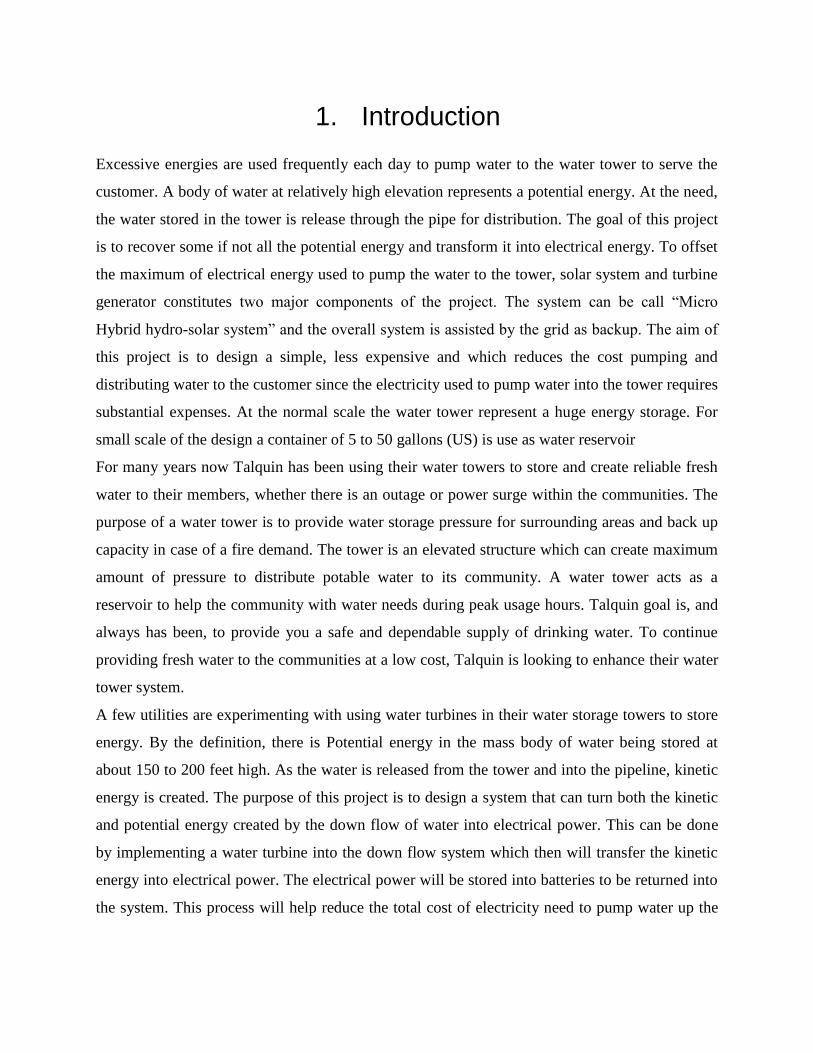
The module can be arranged in parallel/series combination to maximize the output DC power
[4].
Figure: 4 Sample of PV in parallel en series
We will recommend PV tracker for the PV array. The trackers generate more electricity than
their stationary counterparts due to increased direct exposure to solar rays. This increase can be
as much as 10 to 25% depending on the geographic location of the tracking system. There are

many kinds of solar trackers, such as single-axis and dual-axis trackers, all of which can be the
perfect fit for a unique project.
Figure 5: Different type of tracker
3.1.2 PV system Components for small scale
● Panel: One PV panel is intended to be used
● Mounting equipment
● DC charger controller/inverter
● Lead acid battery
● Electrical wire
3.1.3 Advantages of PV
● Clean energy
● Versatile system
● Low maintenance
● Can be stand-alone, grid, or hybrid
● long-life

3.1.4 Disadvantages of PV
● High cost installation and maintenance
● The output DC by PV vary with the solar radiation
● Low efficiency (13 to 18%)
3.2 Microcontroller Unit
In order to control the flow of the electricity base on the need of the sources and the Loads, the
use of MCU is helpful. Different loop is design to implement the goal. The goal of using the
MCU is to alternate the source of the electric power base on the need of the Loads. The
flowchart in figure 5 illustrated the objectives.
Figure: 5 Flowchart of the Microcontroller Unit

3.3 Hydro-system
To calculate theoretically the amount of power that can generate, we must understand how the
water tower work.
Figure 7: Water flow system
The Q𝑖𝑖 is the rate flow at which the water is pumped to the tower, V𝑖𝑖 is the volume of
water pump into the tower. Q𝑖𝑖𝑖 is the outlet flow rate of the water that will generate the
power needed to be harness. is the outlet flow rate. To estimate the power that can be harness, we
proceed as follow:

Per figure 7, it can be shown that the power required to pump fluid into the water reservoir
(tower) is given by the following expression:
Where E is the energy, t is the time, p is fluid pressure at the base of the tower, and Q𝑖𝑖 is
the volumetric flow rate of the fluid into the tower. The water pressure at the base of the tower is
again:
Since the water is incompressible, the volumetric flow rate can be expressed as
where A is the cross-sectional area of the tower.
The volume V of the tank is assumed to be:
Substituting equations (2) and (3) into (1), produces the following expression for hydroelectric
energy stored in the tower (water reservoir):
Equation (5) expressed the energy storage capacity for the tower (reservoir) in joules. To get the
kilowatts-hour,
If this energy discharge over time T (hour) period, the power generate is:
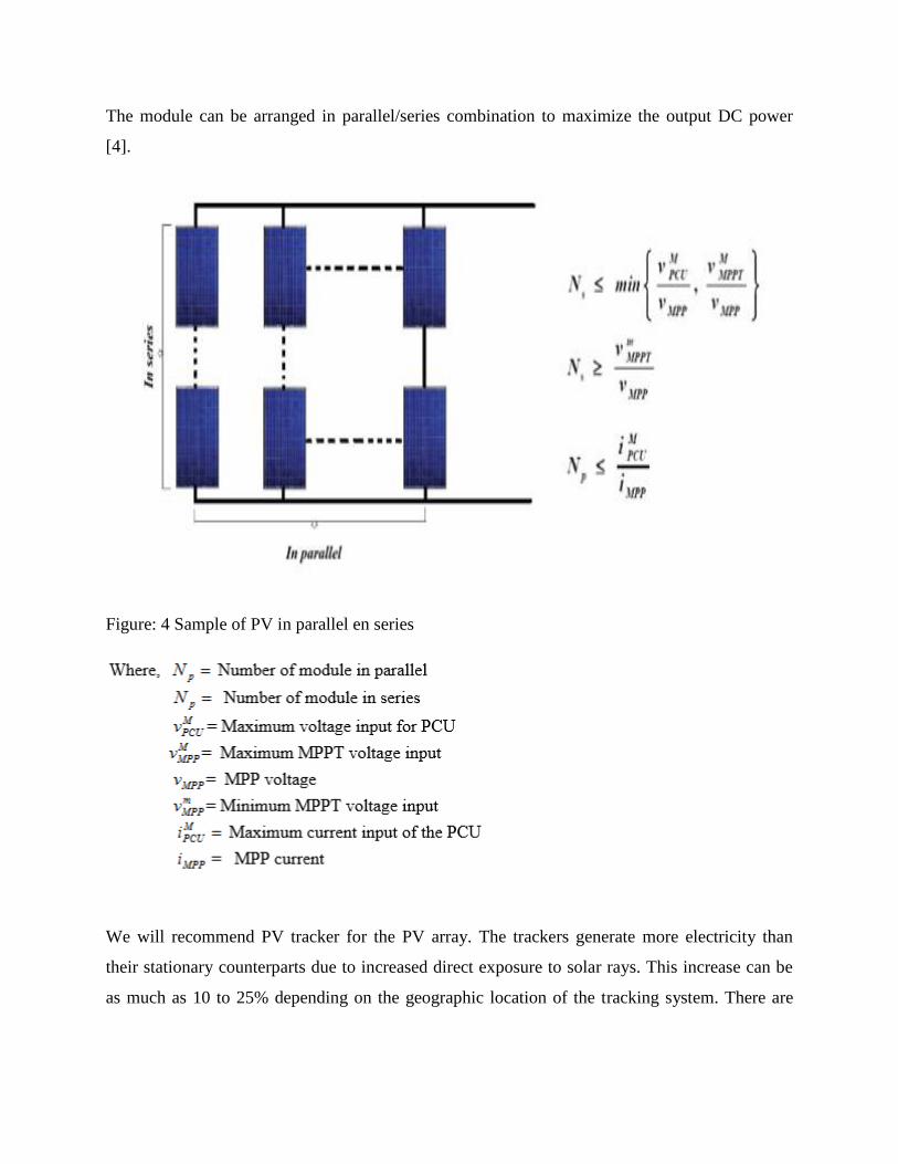
To determine the exact electric power, generated by the water, the inlet flow rate Qin and the
outlet flow rate Qout must be known. It follows that Talquin spend a lot of dollars monthly to
cover the expenses of pumping water to tower. Below are the data.
Table 2: Bradfordville tower billing
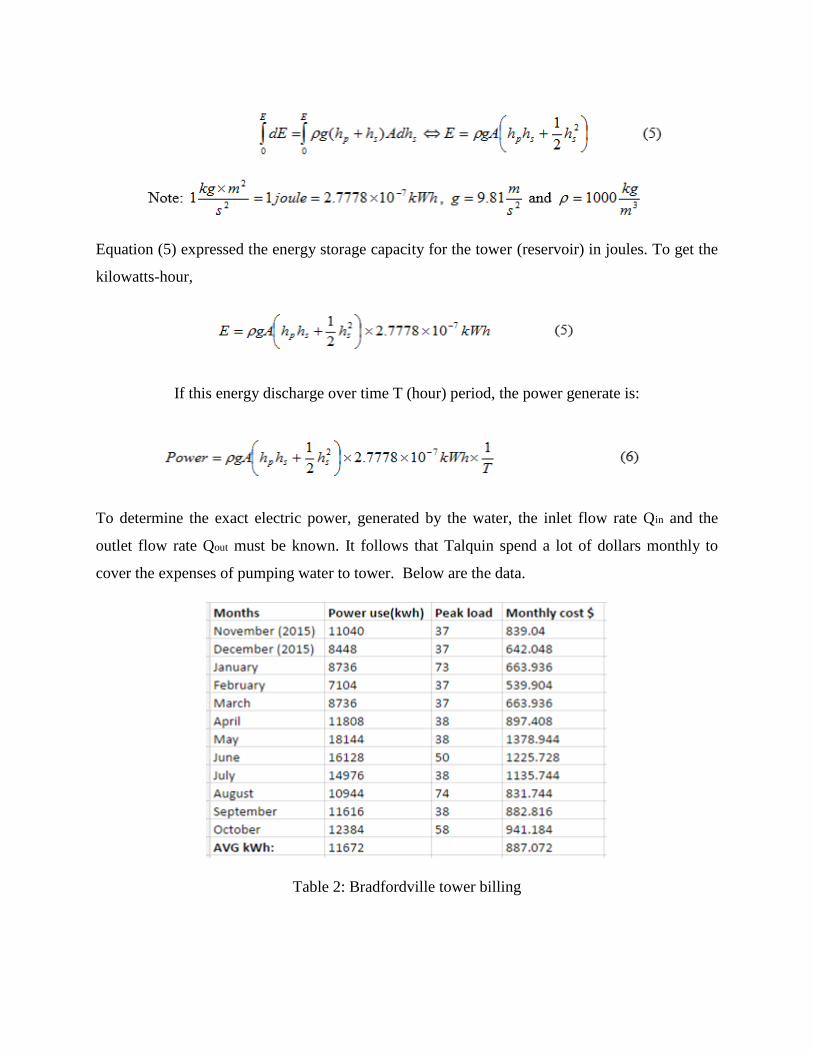
Figure 8: graph showing monthly peak load
Figure 9: graph showing monthly Kilowatts used
Figure 10: graph illustrating monthly bill

The above graph illustrates the cost of pumping the water. The main raison for the project is to
offset some of these expenses. To estimate theoretically a minimum daily power that can be
harness, we were provided a data showing the level of the water inside the tower each hour
during a period of 24 hours.
Figure 11: Data showing the level (in ft) of water
Using the daily data, and the equations (1) through (5) we have:
As result, the total energy that can be harness that typical day is about 60.65 kWh. Note that the
actual energy will be affected by the product of efficiency of all components use to build the
system.
Throughout the project, a solar PV (array) is used to generate some amount of electricity to run
the water pump motor. Therefore, power required to pump water into the reservoir is [6]:
The Horsepower convert into kilowatts is used to size the DC power of the PV (solar panel)
array.
3.4 Turbines
The purpose of a hydro power turbine is to convert the kinetic energy of the oncoming
water through the pipes to electrical energy. The types of hydropower turbines that make this
power generation possible fall into the categories of an impulse or reaction turbine. The type of
hydropower turbine chosen for a system within these two categories are based mainly on the
“head” and flow rate of water in the system. The head is a term used to describe the height of the
standing water to run through the turbine and is broken up into low, medium and high head with
a low head being less than 10 meters, medium head ranging from 10 to 50 meters and a high
head greater than 50 meters.
Impulse turbines use the velocity of water to drive the runner. With a high speed water
stream, the water is directed to hit the bucket of the runner allowing for a rotation of the turbine.
Examples of this turbine includes a Pelton wheel with the runner connected to buckets that

capture the energy of the jet of water. Nearly all of the energy of the water is used to propel the
buckets and the reflected water falls into a discharge channel.
A reaction turbine is the type of turbine that would be better suited for the type of hydro
system Talquin is trying to incorporate. Reason for this being that reaction turbines exploit the
flow of oncoming water to rotate the runner blades. A reaction turbine also doesn’t change the
direction of a fluid as much as an impulse turbine making it more suitable to place with the pipes
that deliver the water to Tarquin's customers.
Hydrokinetic turbines are a type of reaction turbine that use the energy from the flow of
present water. These systems are most efficient with low head, high flow systems that typically
consist of rivers, tidal waves, and ocean currents. A turbine we researched that incorporates this
style of turbine is manufactured at Lucid Energy. The system they have in place captures the
flow of moving water within already present pipes and converts the energy with the installed
generator above. As ideal as this turbine would be for our system, a hydrokinetic turbine requires
a low head, typically up to around 10 meters, which conflicts with our high head at Talquin
standing at roughly 33 meters.
The Francis turbine is another example of a reaction turbine and is the most commonly
used turbine in today’s hydro systems. These turbines are suitable for medium and high head
systems and operate under high efficiency in a wider range of conditions compared to other
turbines which make them so commonly used. The shape of the turbine allows for a constant
velocity flow of the water and an outlet to allow for a recover of pressure within the turbine. A
small Francis turbine would be best suited for Talquin being that it fulfills a majority of the
requirements of this type of turbine, in terms of head and flow rate, to extract the most energy of
the flowing water. Because of the large head requirement of this type of turbine, we will not be
able to use it for a final scaled down model and plan to build or purchase a small turbine to act as
how a larger Francis one would work in real life.

Fig[12]
With the restricted head and flow rate of the small-scale model being much smaller than
the ones for Talquin, we found that a reaction turbine would be better suited to generate
electricity. Regarding the small-scale model that we plan to build for our final design, research
has been conducted to find a mini hydro power generator to apply the same concept researched
for Talquin to generate electricity from the flowing water. The models that have been narrowed
down to have been the PowerSpout, Zurn Industries, and Water buddy systems.
The PowerSpout PLT is a Pelton type turbine as shown in Figure 13 below. With
a minimum flow of 0.8 gpm and head range from 10 to 430 feet, this turbine has the potential to
be utilized within our system. The main draw back with this turbine is its cost, being $1,599,
which would be a huge part of our $2,000 budget. It is for this reason that we have kept this
turbine in mind but have looked onwards to other systems.
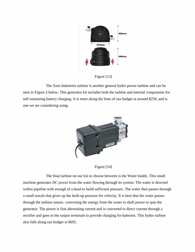
Figure [13]
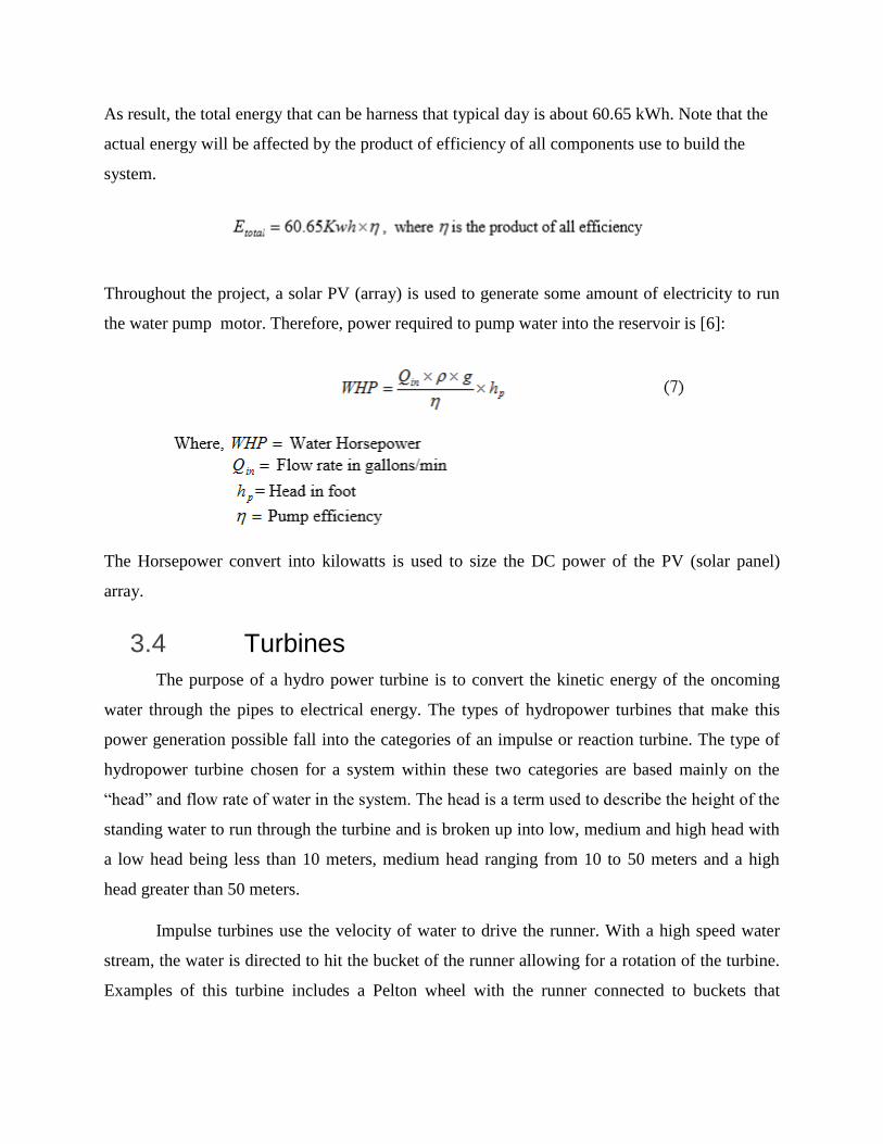
The Zurn Industries turbine is another general hydro power turbine and can be
seen in Figure 2 below. This generator kit includes both the turbine and internal components for
self-sustaining battery charging. It is more along the lines of our budget at around $250, and is
one we are considering using.
Figure [14]
The final turbine on our list to choose between is the Water buddy. This small
machine generates DC power from the water flowing through its system. The water is directed
within pipeline with enough of a head to build sufficient pressure. The water then passes through
a small nozzle that gives up the built-up pressure for velocity. It is here that the water passes
through the turbine runner, converting the energy from the water to shaft power to spin the
generator. The power is first alternating current and is converted to direct current through a
rectifier and goes to the output terminals to provide charging for batteries. This hydro turbine
also falls along our budget at $695.

Figure [15]
Once more calculations are completed such as the flow rate with the compressor that will
be in place with our system we will then be able to make an informative decision on which
turbine to move forward with.
3.5 Battery
Being a very essential component of electronic devices, the battery is one of the most
researched devices in the field of electricity. A battery is a device that converts the chemical
energy contained in its active materials directly into electric energy by means of an
electrochemical oxidation-reduction (redox) reaction. In a rechargeable system, the battery is
recharged by a reversal of the process. This type of reaction involves the transfer of electrons
from one material to another through an electric circuit. All batteries are made up of three basic
components: an anode (the Negative side), a cathode (the positive side), and electrolyte (a
substance that chemically reacts with the anode and cathode). It is important to understand that
batteries come in many different sizes and designs. They are made of an array of different
chemicals, and can store any amount of energy based on size.
Lead Acid Battery was invented by the French physician Gaston Planté in 1859, and was
the first rechargeable battery for commercial use. Despite its advanced age, the lead chemistry
continues to be in wide use today. There are good reasons for its popularity; lead acid is
dependable and inexpensive on a cost-per-watt base. There are few other batteries that deliver

bulk power as cheaply as lead acid, and this makes the battery cost-effective for automobiles,
golf cars, forklifts, marine and uninterruptible power supplies (UPS).
The grid structure of the lead acid battery is made from a lead alloy. Pure lead is too soft
and would not support itself, so small quantities of other metals are added to get the mechanical
strength and improve electrical properties. The most common additives are antimony, calcium,
tin and selenium. These batteries are often known as “lead-antimony” and “lead calcium.”
The first signs of the lithium battery began in 1912 under G.N. Lewis but it was not until
the early 1970s when the first non-rechargeable lithium batteries became commercially available.
Lithium is the lightest of all metals, has the greatest electrochemical potential and provides the
largest energy density for weight.
Attempts to develop rechargeable lithium batteries failed due to safety problems. Because
of the inherent instability of lithium metal, especially during charging, research shifted to a non-
metallic lithium battery using lithium ions. Although slightly lower in energy density than
lithium metal, lithium-ion is safe, provided certain precautions are met when charging and
discharging. In 1991, the Sony Corporation commercialized the first lithium-ion battery. Other
manufacturers followed suit.
The energy density of lithium-ion is typically twice that of the standard nickel-cadmium.
There is potential for higher energy densities. The load characteristics are reasonably good and
behave similarly to nickel-cadmium in terms of discharge. The high cell voltage of 3.6 volts
allows battery pack designs with only one cell. Most of today's mobile phones run on a single
cell. A nickel-based pack would require three 1.2-volt cells connected in series.
Lithium-ion is a low maintenance battery, an advantage that most other chemistries
cannot claim. There is no memory and no scheduled cycling is required to prolong the battery's
life. In addition, the self-discharge is less than half compared to nickel-cadmium, making
lithium-ion well suited for modern fuel gauge applications. lithium-ion cells cause little harm
when disposed.
Despite its overall advantages, lithium-ion has its drawbacks. It is fragile and requires a
protection circuit to maintain safe operation. Built into each pack, the protection circuit limits the
peak voltage of each cell during charge and prevents the cell voltage from dropping too low on

discharge. In addition, the cell temperature is monitored to prevent temperature extremes. The
maximum charge and discharge current on most packs are is limited to between 1C and 2C. With
these precautions in place, the possibility of metallic lithium plating occurring due to overcharge
is virtually eliminated.
Comparing Lead Acid vs. Li-ion Battery
Characteristics Lead acid LifePO4
Weight Very heavy 1/3 of lead acid weight
Efficiency Inefficiency,
*Reduce the battery capacity
About 100% Charge-
Discharge
*Same amp hour in-out
Discharge 80% 100%
Cycle life 400-500 cycles in lead acid
1-2 years
Rechargeable lithium-ion
batteries cycle 5000 times or
more
3-5 years
Voltage Voltage drops consistently
throughout the discharge
cycle
lower Voltage (2V)
Maintain their voltage
throughout the entire
discharge cycle = longer-
lasting efficiency of electrical
components
Higher voltage (3.7V)
Cost Low cost **Higher upfront cost
Environmental Impact Not environmental friendly much cleaner technology and
are safer for the environment.
Table: 3 Lead Acid vs. Li-ion Phosphate battery
Solar Power Conditioning Unit (PCU) is an integrated system consisting of a solar
charger, inverter, Grid charger and control algorithm.
● Solar charger- collects the solar energy collected by the (SPV) to power the system.

● Inverter- converts the DC to AC where needed.
● Grid charger- powers the system when the solar panels is inadequate.
● Control Algorithm- allot priority and optimally select the source of charging
(microprocessor).
● The PCU is usually designed and built based on customer demand.
After completing more research on both the large scaling and small scaling of the system,
there will be a few changes made between the two. For the large-scale system, it has been
decided that no battery bank is necessary to store the newly produced energy. Instead, there will
be a PCU in sequence with the system to transfer the power from both the turbine generator and
the PV arrays directly to the grid to save money and time. The PCU is designed to take both AC
and DC current and transform them to the needed current and frequency to be able to deliver it
where needed. This process will save thousands of dollars from having to design and purchase a
high efficiency energy storage system to store the new power.
In the smale scale of things, there will be a purchase of a 48V DC lead acid battery to
match the solar panel. Lead Acid battery is best for this system because of its cost and high usage
and today’s society. This battery will need to be able to receive current that is transformed from
AC to DC using an inverter. The purpose of this inverter is simply to take any AC current
produced from an energy source to transform it into DC current in order to store that power
within the battery. The Ideal frequency for this system should be 60hz in order to use it to power
most modern day equipment in America. Due to the constant of storing and releasing of energy,
the battery will need to have a very high charge and discharge cycles.
4. Results
A summary of results is given in Table 4. The result table starts with the measurement values of
water tower, follows by an estimation of energy using the data provided. Currently no testing or
building is being completed of the small scale model for this project. All building will be done at
a later time.

Quantity or Given Results
Height of water tower h𝑖 160 ft
Height of water level in tank h𝑖 30 ft
Area of water tank 2827.4 sq ft
Volume of tank 250,000 US gallons
Inlet flow rate of water 1000 gallons/min
Outlet flow rate using daily data provided 2.74 gallons/sec
Cost per kWh required for pump 7.6 cents
Power required for pump 75 kW
Total storing capacity of water tower 349.141 kWh
Energy calculated using daily data provided 60.65 kWh
Amount of dollars save using daily data provided $4.61
Monthly saving using daily data provided (exclude peak load) $138.3
Yearly saving using daily data provided (exclude peak load) $1659.38
Table 4: Result table
5. Small Scale
● (2) 5 gallons tanks, 1 for reservoir, 1 for storage on tower
● Turbine generator
● LED
● Battery
● PVC Pipe
● Pressure gauge
● Charger controller
● MCU/ PCU
● 2 units of Directional-Control valves
● DC Water Pump
● 4 units PVC 90 Degree Elbow
● 1 units of 1 in. PVC Slip In-Line Check Valve
● 3 units water Gauge

● Air Compressor
6. Potential Challenges
As the design becomes more refined, potential challenges that may occur is wetting of
components. Another challenge that may occur is stabilizing of pressure into turbine. Pressure
stability is a must in order to achieve the maximum RPM in the turbine to harvest energy from
flowing water. The team must create a small-scale model easy to assemble for showcasing. A
challenge for this project is making sure flow of water does not flow backwards into pump. If
this occurs, this can damage the pump causing pump to overheat, cause boiling of water in rotor
and scroll. Another potential challenge the team may face is not generating enough energy to
charge the battery bank or light LED used.
7. Future plans
In the upcoming weeks, the team will finalize the design of their small-scale model. Each
component will be determined and ready for purchase and building. The size of the pump must
be determined before one can order and test. In order to figure out which pump will be great for
the project, the group has to figure out the rate of speed gpm (gallons per minute) that water can
flow from source to discharge point, vertical suction lift, maximum head lift and energy required
to start pump. PVC piping depends on the pump chosen. Team 5 will determine the miniature
turbine required for the small scale and test. The team will work together to figure out how much
pressure and speed of water must be needed to spin blades of turbine to generate electricity. In
order to create a certain, pressure the team will need to determine the head of the tower. An air
compressor will help create pressure needed to drive water into the turbine selected. Team 5 will
work together to build a base for the tower to sit on. The team must also finalize the
microcontroller chosen to run the system. Once all these components are figured the team will
order parts and start assembling and testing their model.
8. Risk Assessment Summary
This Section of the paper is for problematic issues that may arise throughout the course of this
project. During the process of designing this project many risks came to mind. Budget control
has come to mind when designing this project. Team 5 has a budget limit of $2000, the

complexity of this design can result in a possibility of going over budget. Components such as,
pumps, air compressor, and turbine generator kit can be expensive. While dealing with electrical
equipment such as a battery, turbine generator, microcontroller, pump, harm can happen to its
operators due to high voltage being used. Also, since the project will focus on having a water
reservoir and a tank to pump water into can cause electrical components to get wet, if not
properly sealed can cause shock to the operator. Overheating of parts can be a risk as well, if a
battery overheats, can cause material inside of the battery to deteriorate causing the battery not to
work properly. Overheating of any component in the design can cause burns to the operator.
Another risk that came to mind, is the improper use of machinery to build our small-scale model.
Improper use of power tools can cause severe damage to operators. All these risks can be
remedied by proper usage of safety eye, ear and hand protection. If an incident occurs during
project proper authorities will be alerted.
9. Conclusion
The purpose of this project is to determine if the development and implementation of a system
that transfers kinetic energy into electrical power in a water tower system will be cost efficient.
Talquin is hoping to improve their water tower system where electrical power can be stored and
reused in the system by using a water turbine to transfer kinetic energy of down flowing water
into electricity energy. The electrical energy will be then stored into battery cells and then reused
into the system. This will be achieved by researching water tower system and determining which
water turbine and battery source that would be most efficient and cost friendly. The next step for
the team is to research and learn about water turbine and to understand its functions and use.
Then the team will do research on energy storage devices to learn more about their store
capacities and how efficient they are. The ultimate goal of this experiment is to obtain some
energy from the down flow of water from the water tower and to use it to supply power back into
the system to lower the Energy cost on powering the system.

References
[1] Advameg, Inc. "Chapter 1 The Development of Energy." The Development of Energy. N.p.,
n.d. Web. 29 Sept. 2016.
[2] Perlman, USGS Howard. "Hydroelectric Power Water Use." Hydroelectric Power and
Water. Basic Information about Hydroelectricity, the USGS Water Science School. N.p., n.d.
Web. 29 Sept. 2016.
[3] Mason, Matthew. "Renewable Energy: All You Need to Know." Introduction to Renewable
Energy. N.p., n.d. Web. 29 Sept. 2016.
[4] F. Omar, ‘Photovoltaics Design, Integration and Modeling’, FAMU-FSU College of
Engineering, 2015.
[5] “How much hydropower power can I get - Renewables First.” [Online]. Available:
http://www.renewablesfirst.co.uk/hydropower/hydropower-learning-centre/how-much-power-
could-i-generate-from-a-hydro-turbine/. [Accessed: 24-Oct-2016].
[6] “The Mathematics of Pumping Water - Royal Academy of ...” [Online]. Available:
http://www.raeng.org.uk/publications/other/17-pumping-water. [Accessed: 24-Oct-2016].
[7] I. Buchmann, "Lead-based batteries information – battery university," in Battery University,
2016. [Online]. Available: http://batteryuniversity.com/learn/article/lead_based_batteries.
Accessed: Oct. 25, 2016.

*Biography
Darius Wright-Tippins:
Darius Wright-Tippins is a Senior Electrical Engineering student at Florida A&M
University. He is from New York City, and is currently pursuing his B.S. in Electrical
Engineering, his expected graduation date is April 2017. Darius has always been fascinated with
electrical work since a young age, which caused him to pursue Electrical Engineering in school.
Darius is currently taking Power System Analysis to gain knowledge of power and energy. His
goal is to work in the power industry after graduation.
Moise Zamor:
Moise Zamor is a Senior Electrical Engineering Major at Florida State University. He is
currently seeking his bachelors in Electrical Engineering with a focus in power systems. He was
raised in a strong Christian home where he received his morals and values. From Fort
Lauderdale, Florida. Zamor is known for his love with working with power electronics and
systems. As a child, he would always attempt to fix broken devices and appliances. He is
expected to graduate in April 2017. Based on his skill sets and love for power systems. Moise
Zamor will be a great addition for any company or corporation looking for an electrical
Engineer.
Komlan Amessee:
Komlan Amessee is a senior Electrical Engineering student at Florida State University.
Komlan is Originally from Togo Africa. He is currently pursuing his B.S. in Electrical
Engineering, expecting to graduate April 2017. Komlan is currently taking Power System
Analysis and Microcontroller Based System Design to gain knowledge of power/energy and
structured assembly-language software design, RTL, CPU design, pipelining and superscaling,
computer arithmetic, memory and I/O organization and interface, cache, and design tools.

Olivier Perrault:
Olivier Perrault is a senior electrical engineering student at Florida State University
pursing a Bachelor’s degree with a focus in Power. Originally from Ft. Lauderdale, Florida he
plans on acquiring a position as a Project/Field engineer for a General or Electrical contracting
company upon graduation in May of 2017. He has previously taken Power Electronics and is
currently taking Fundamentals of Power systems to further his knowledge in the field of Power.