replacement of the belle river pontoon bridge
TRANSCRIPT

HEAVY MOVABLE STRUCTURES, INC. TWELFTH BIENNIAL SYMPOSIUM
Replacement of the Belle River Pontoon
Bridge
Mark Green, P.E., Project Mechanical Engineer HNTB Corporation
715 Kirk drive Kansas City, MO 64105
Phone 816 472 1201

Abstract The Belle River Bridge is a floating pontoon bridge that pivots to open for waterway traffic. Located on LA Route 70 in Assumption Parish, Louisiana, the bridge provides an important waterway crossing on a route from Baton Rouge to Morgan City along the Atchafalaya waterway. The original bridge was constructed in 1958 and was deemed deficient. Trucks were required to cross along the centerline of the bridge to reduce the torsional deflection of the bridge. The existing pontoon span was opened and closed with operating ropes that dipped in the water and failed frequently. The moving approach spans (apron spans) are similar to ferry transfer spans and lifted to allow the pontoon span to swing open. The apron spans are counterweighted, and the counterweight ropes and machinery encountered frequent failures. Picciola and Associates was selected by the LADOTD as the naval architect for the new pontoon, and Picciola selected HNTB for a new mechanical and electrical design that would eliminate the nagging failures of the existing systems.
Several concepts were developed for operation of the spans. This paper presents the challenges and resolutions for selecting a concept, and carrying it forward through construction to stabilize and replace this unique bridge.
Introduction The existing LA Route 70 Belle River Bridge is a floating pontoon span constructed in 1958. The existing bridge consists of a 130’ long, 28’-4” wide floating pontoon span. A 15’-6” movable apron span at each end of the pontoon span transfers traffic from the pontoon to a series of 20’ concrete fixed approach spans located at each end of the bridge. The existing bridge plan and elevation is shown Figure 1 below.
The LADOTD is currently replacing pontoon spans with other types of spans; however, local residents and leaders like the appearance of the pontoon span, and want to keep that style.
The pontoon span opens and closes by rotating laterally about a pivot bearing attached to a
fixed pivot pier. A pivot arm is attached to the pontoon span and the pivot bearing with pins to accommodate different floating elevations of the pontoon span. The pontoon span is moved by operating ropes attached to a winch with two speed-synchronized operating drums; one drum
Figure 1 Existing Bridge Layout
HEAVY MOVABLE STRUCTURES, INC. 2 12th Biennial Movable Bridge Symposium
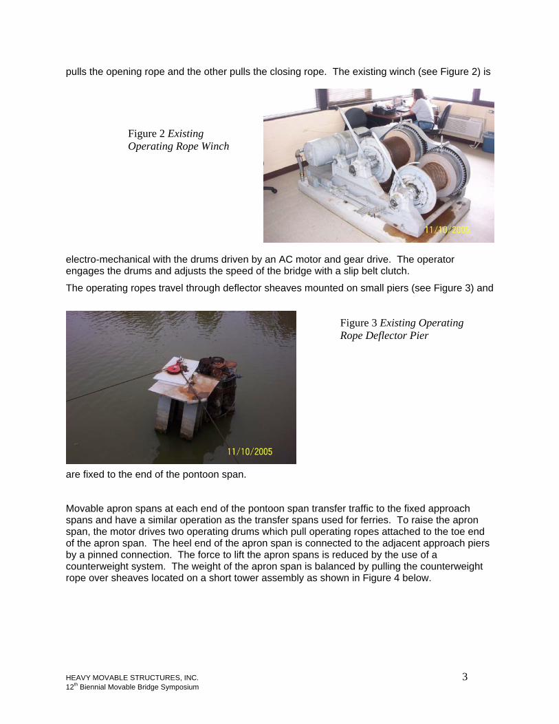
pulls the opening rope and the other pulls the closing rope. The existing winch (see Figure 2) is
electro-mechanical with the drums driven by an AC motor and gear drive. The operator engages the drums and adjusts the speed of the bridge with a slip belt clutch.
Figure 2 Existing Operating Rope Winch
The operating ropes travel through deflector sheaves mounted on small piers (see Figure 3) and
are fixed to the end of the pontoon span.
Figure 3 Existing Operating Rope Deflector Pier
Movable apron spans at each end of the pontoon span transfer traffic to the fixed approach spans and have a similar operation as the transfer spans used for ferries. To raise the apron span, the motor drives two operating drums which pull operating ropes attached to the toe end of the apron span. The heel end of the apron span is connected to the adjacent approach piers by a pinned connection. The force to lift the apron spans is reduced by the use of a counterweight system. The weight of the apron span is balanced by pulling the counterweight rope over sheaves located on a short tower assembly as shown in Figure 4 below.
HEAVY MOVABLE STRUCTURES, INC. 3 12th Biennial Movable Bridge Symposium

Figure 4 Apron Span Machinery
Operational Difficulties
Pontoon Span Rotational Stability Heavy vehicles traveling over the pontoon span would cause the pontoon to rotate about the longitudinal bridge axis. This resulted in a rotational misalignment between the pontoon span and the apron spans at each end. Misalignments as much as 4 inches were observed when large trucks crossed the bridge. As trucks crossed from the pontoon span onto the apron span wheel loads would force the apron span down to meet the pontoon span. Trucks would attempt to wait until on-coming traffic cleared and cross the pontoon span at the centerline, but of course this was not possible under all traffic conditions.
Counterweight Failures The rotational stability of the pontoon span also had a dramatic effect on the apron span machinery. Wheel loads forcing the apron span down caused the apron span counterweight
system to have many failures. Counterweight ropes failed prematurely, and counterweight guides failed. The counterweight guides were eccentric to the counterweight center of gravity. As the apron span was forced down the counterweights bounced vertically. The eccentricity
Figure 5 Apron Span Bent Counterweight Guides
HEAVY MOVABLE STRUCTURES, INC. 4 12th Biennial Movable Bridge Symposium

caused bending in the guides that eventually led to failure as shown in Figure 5. The guides failed so frequently that additional wire ropes were added to the counterweights, so that they could be retrieved from the water.
Operating Rope Failures Pontoon operating rope failures occurred often. The cause is thought to be 1) the sheave diameters are too small for a 3/4” diameter operating rope, and 2) the ropes are constantly in the water. The closing rope for the span stretches across the channel when the bridge is in the open position where vegetation keeps it from sinking and passing vessels can snag it. (See Figure 6)
Alleviation of the recent problems was an important factor in the new bridge design.
Figure 6 Closing Operating Rope in the Channel
Design Goals Based on the failures mentioned in the above section, design goals were established to alleviate the problems in the mechanical systems.
Pontoon Span Modify the pontoon for increased torsional stability.
Pontoon Span Machinery Eliminate ropes or keep them out of the water and use larger diameter drums and deflector sheaves to increase rope life.
Apron Span Machinery Eliminate tower and counterweights from apron span machinery
Control House The control house was replaced in 2003, so reuse the existing control house.
Concrete Approach Spans Reuse concrete approach spans.
Machinery Type Study A type study was performed to determine the best machinery system to move the new pontoon and apron spans. Three machinery options for powering the pontoon span were selected for
HEAVY MOVABLE STRUCTURES, INC. 5 12th Biennial Movable Bridge Symposium

further analysis: 1) use operating ropes with a new arrangement, 2) use hydraulic cylinders mounted to a larger pivot pier, or 2) use bow thrusters integral to the pontoon span. Two options to move the apron span were considered: 1) a modified operating rope system, and 2) hydraulic cylinders. Neither option includes a counterweight.
The electrical control system for all options would consist of control relays, motor control center, distribution system and a control console. The control system would be used to control the apron and pontoon spans, and provide the necessary interlocks to prevent each system from operating out of normal sequence.
Pontoon Machinery Rating Ratings were developed to aid in evaluation. A raw score between 1 and 10 was given to individual aspects of each machinery option. The higher the score, the more desirable the aspect is relative to the other machinery options. This raw score was then multiplied by a weighting factor to determine the rating. An example rating table is shown below. A discussion of the advantages and disadvantages of each option is presented in the following paragraphs.
Feature Rating Raw Score
Weighing Factor
Weighed Score Description
Complexity 10
Span Controllability 25
Maintenance 15
Life Cycle 15
Machinery Cost 20
Elect. System Cost 20
Structural Cost 20
Construction Considerations 10
Total
Note:1) 10 is most desirable, 1 is least desirable
Pontoon Machinery / Option 1 Operating Ropes The operating rope drive is used on many pontoon bridges in the State of Louisiana, and swings the pontoon span using operating ropes, one to open, and one to close. Each rope is attached at one end to a winch drum and attached to the pontoon span on the other end. The operating ropes travel around deflector sheaves mounted to the tops of small pile supported piers. A winch with two drums would be placed on the lower level of the control house or on a platform suspended below the control house. The winch is powered by a hydraulic power unit that is controlled by a joystick. Control of the span is maintained at all times by controlling the tension in the operating ropes.
The drive system uses a joystick at the control console and variable flow hydraulics to provide speed control for the span.
HEAVY MOVABLE STRUCTURES, INC. 6 12th Biennial Movable Bridge Symposium

Pontoon Machinery / Option 2 Hydraulic Cylinders This machinery option would apply a torque to the pontoon swing arm using hydraulic actuators, a low speed high torque hydraulic motor, or a gear driven machinery to move the pontoon span to the open and closed position. Since the pontoon span moves vertically and causes the swing arm to pitch, a complex attachment to the swing arm pivot would be required for this option. The initial cost of gear driven machinery and a low speed high torque motor is expected to be higher than hydraulic actuators, only the hydraulic actuator configuration was chosen for the comparison. The actuators would be powered by a hydraulic power unit that contains two variable flow axial piston pumps for redundancy. Both pumps operating simultaneously would open the span in a similar time to the operating rope option. If one pump is not operable, the time to open the span would double.
The drive system would use a joystick at the control console and variable flow hydraulics to provide speed control for the span. Two 40 HP motors would likely be required for this arrangement.
A large pivot pier would be required to locate and support the hydraulic actuators. Each drive cylinder would require a long stroke and need to be around 12-14 inches in diameter for a 1200 psi operating pressure.
Pontoon Machinery / Option 3 Bow Thrusters Bow or outdrive type thrusters could be used to move the pontoon span. Two thrusters would be mounted at the end of the pontoon span for redundancy. The two thrusters would open the span in a similar time as the other options. Operation with one thruster would take twice as long. The thrusters are driven by variable speed DC motors and drive controllers for smooth acceleration and deceleration.
The most effective method to control the speed of bow thruster motors would be with a variable speed control drive controller and a joystick on the main control console. Variable speed controllers would be required to assure that the operator would have continuous control of the floating span to prevent river currents from causing the speed of the span to increase above the operational speed.
There are several disadvantages of this type of drive system: the inefficiencies of pushing water with a propeller would require significantly higher motor power to produce the same amount of torque at the pivot point as the other options. The thrusters would need approximately 150 HP each versus 30-40 HP. Another significant disadvantage is a lack of span control. A thruster cannot maintain the position of the bridge against the forces of river current or marine vessel wakes unless it is constantly providing thrust. The span would become uncontrollable if the thruster failed or power was lost. Additionally, dense marine vegetation in the area around bridges would likely produce maintenance problems for the thruster. Access for a bow thruster arrangement would be difficult since it would be built into the pontoon and be underwater. An out-drive thruster arrangement would allow the propeller to be lifted out of the water for servicing, but would require additional machinery to lift assembly (i.e. hydraulic cylinders).
Pontoon Machinery Rating Summary Ratings for the three pontoon machinery options are tabulated and summarized below. Mechanical costs were determined that quantify the costs associated with each option. Relative electrical costs due to the option chosen were determined and added to the mechanical costs. These costs are also presented in the pontoon summary.
HEAVY MOVABLE STRUCTURES, INC. 7 12th Biennial Movable Bridge Symposium
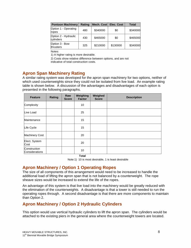
Pontoon Machinery Rating Mech. Cost Elec. Cost Total Option 1 - Operating ropes 480 $340000 $0 $340000
Option 2 - Hydraulic cylinders 430 $465000 $0 $465000
Option 3 - Bow thrusters 325 $210000 $130000 $340000
Notes: 1) A higher rating is more desirable. 2) Costs show relative difference between options, and are not indicative of total construction costs.
Apron Span Machinery Rating A similar rating system was developed for the apron span machinery for two options, neither of which used counterweights since they could not be isolated from live load. An example rating table is shown below. A discussion of the advantages and disadvantages of each option is presented in the following paragraphs.
Feature Rating Raw Score
Weighing Factor
Weighed Score Description
Complexity 10
Live Load 25
Maintenance 15
Life Cycle 15
Machinery Cost 20
Elect. System Cost 20
Construction Considerations 10
Total Note: 1) 10 is most desirable, 1 is least desirable
Apron Machinery / Option 1 Operating Ropes The size of all components of this arrangement would need to be increased to handle the additional load of lifting the apron span that is not balanced by a counterweight. The rope sheave sizes would be increased to extend the life of the ropes.
An advantage of this system is that live load into the machinery would be greatly reduced with the elimination of the counterweights. A disadvantage is that a tower is still needed to run the operating ropes through. A second disadvantage is that there are more components to maintain than Option 2.
Apron Machinery / Option 2 Hydraulic Cylinders This option would use vertical hydraulic cylinders to lift the apron span. The cylinders would be attached to the existing piers in the general area where the counterweight towers are located.
HEAVY MOVABLE STRUCTURES, INC. 8 12th Biennial Movable Bridge Symposium

The attachment to the apron span would be slotted to allow for movement of the apron span under live load without imparting forces into the hydraulic cylinder.
An advantage of this arrangement is that the machinery is greatly simplified. No live load is transferred into the machinery, therefore the system would be more reliable. Maintenance would be simplified as there would be fewer machinery parts to maintain.
Apron Machinery Rating Summary Ratings for the two apron machinery options are tabulated and summarized below. Mechanical costs were determined that quantify the costs associated with each option. Relative electrical costs due to the option chosen were determined and added to the mechanical costs. These costs are also presented in the pontoon summary.
Pontoon Machinery Rating
Option 1 - Operating ropes 470
Option 2 - Hydraulic cylinders 970
New Design Features
Pontoon Stability The rotational stability of the pontoon was increased by adding additional 15’ x 30’ compartments to the corners of the pontoon and increasing the length from 130 feet to 135 feet. The new bridge layout and assembled pontoon is shown in Figures 7 and 8, respectively.
Figure 7 Bridge Layout
HEAVY MOVABLE STRUCTURES, INC. 9 12th Biennial Movable Bridge Symposium

Figure 8 Assembled Pontoon Span
Pontoon Machinery The pontoon machinery consists of a rope winch with one drum for each operating rope. A layout of the ropes is shown below in Figure 9. A hydraulic motor powered by a hydraulic power unit was chosen to give the operator precise speed control for the pulling rope. A photo of the power unit and winch during shop testing is shown below in Figure 10.
Figure 9 Operating Rope Layout
HEAVY MOVABLE STRUCTURES, INC. 10 12th Biennial Movable Bridge Symposium

Apron Span Machinery The apron spans are driven by hydraulic cylinders powered by a hydraulic power unit. The cylinder configuration and Hydraulic Power Unit are shown below in Figures 11 and 12, respectively.
Figure 11 Apron Span Hydraulic Cylinder
Figure 10 Winch and Hydraulic Power Unit
Figure 12 Apron Span Hydraulic Power Unit
HEAVY MOVABLE STRUCTURES, INC. 11 12th Biennial Movable Bridge Symposium

Summary The existing pontoon span was opened and closed with operating ropes that dipped in the water and failed frequently. The moving approach spans were counterweighted, and the counterweight ropes and machinery encountered frequent failures due to live load impacts on the span. In order to alleviate the failures, a more stable pontoon barge was developed, and new operating machinery concepts were studied to eliminate the nagging failures of the existing systems.
A wider pontoon was designed and constructed to provide increased stability for truck traffic. Since the rotation of the pontoon is decreased, the wheel loads transitioning to the apron span are also decreased. New hydraulic apron span machinery was designed to operate without a counterweight. Operating ropes are still used to move the pontoon span, but they are reconfigured so that crossing the channel is not necessary.
Construction of the pontoon is scheduled to be completed late 2008.
HEAVY MOVABLE STRUCTURES, INC. 12 12th Biennial Movable Bridge Symposium