repair service instructions calibration
TRANSCRIPT
MILWAUKEE ELECTRIC TOOL CORPORATION – TEST & MEASUREMENT PRODUCT
REPAIR SERVICE INSTRUCTIONS — CALIBRATION 2217-20 TRUE-RMS MULTIMETER
Environmental Condition
Perform all calibration at an ambient temperature of 23°C ± 2°C / 73.4°F ± 3.6°F and relative humidity of 80% - allow the digital multimeter to sit at this temperature for a minimum of 30 minutes before proceeding.
REPAIR SERVICE INSTRUCTIONS
Calibration
MILWAUKEE ELECTRIC TOOL CORPORATION 13135 WEST LISBON ROAD BROOKFIELD, WISCONSIN 53005-2550 USA
58-92-2217d3 02/2014
i
TABLE OF CONTENTS Page
Introduction 1
1 noitamrofnI ytefaS dna snoituacerP
Symbols 1
Safety 2
Specifications 3
3 noitacificepS lareneG
4 noitacificepS egatloV
5 snoitacificepS tnerruC
6 snoitacificepS ecnaticapaC ,ytiunitnoC ,ecnatsiseR
Frequency, Temperature, Thermocouple, Rotary Switch, Auto Power Off Specification 7
9 scitsiretcarahc tnemnorivne dna lacisyhP
9 ecnailpmoc dna noitacifitreC
01 tnempiuqE deriuqeR
Basic Maintenance 11
11 esaC reteM eht gninepO
11 yrettaB eht gnicalpeR
Testing Fuses 12
Replacing Fuses 12
Cleaning 12
Performance Tests 13
31 yalpsiD eht gnitseT
41 noitcnuF egatloV eht gnitseT
Testing the Resistance 51 noitcnuF
51 noitcnuF ecnaticapaC eht gnitseT
Testing the Ampere 61 noitcnuF
61 noitcnuF tnerruC eht gnitseT
61 noitcnuF ycneuqerF eht gnitseT
Testing the Temperature 71 noitcnuF
Calibration 18
1
Introduction
WARNINGTo avoid shock or injury, do not perform the verification tests or calibration procedures described in the manual unless you are qualified to do so. The information provided in this document is for the use of qualified personnel only.
CAUTION
The 2217-20 contain parts that can be damaged by static discharge. Follow the standard practices for handling static sensitive devices.
Precautions and Safety Information
Use the Meter only as described in the Operator’s Manual. If you do not do so, the protection provided by the Meter may be impaired. Read the “Safety Information” page before servicing this product. In this manual, a WARNING identifies conditions and actions that pose hazard (s) to the user; a CAUTION identifies conditions and actions that may damage the Meter or the test instruments.
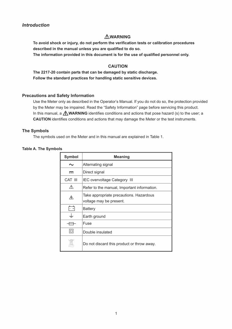
The Symbols
The symbols used on the Meter and in this manual are explained in Table 1. Table A. The Symbols
Symbol Meaning
Alternating signal
Direct signal
CAT III IEC overvoltage Category III
Refer to the manual, Important information.
Take appropriate precautions. Hazardous voltage may be present.
Battery
Earth ground
Fuse
Double insulated
Do not discard this product or throw away.
++
2
Use proper Fuse. To avoid fire hazard, use only the fuse type and rating specified for this product, 10A / 600V Fast-acting (Cat. No. 22-89-0300). For fuse replacement, it is recommendedto return the tool to a factory Service/Sales Support Branch or authorized service station.
SAFETY Review the following safety precautions to avoid injury and prevent damage to this product or products connected to it. To avoid potential hazards, use the product only as specified.
CAUTION: These statements identify conditions or practices that could result in damage to
the equipment or other property.
WARNING: These statements identify conditions or practices that could result in personal
injury or loss of life.
Specific precautions
Do not operate without covers. To avoid personal injury, do not apply any voltage or current to the product without covers in place. Electric overload. Never apply a voltage to a connector on the product that is outside the range specified for that connector. Avoid electric shock. To avoid injury or loss of life, do not connect or disconnect probes or test leads from the meter while they are connected to a voltage source. Do not operate in wet/damp conditions. To avoid electric shock, do not operate this product in wet or damp conditions.
To reduce the risk of injury, user must read and understand operator’s manual.

3
SPECIFICATIONS All specifications are warranted unless noted typical and apply to the 2217-20 DMM.
Stated accuracies are at 23°C±5°C at than 80% relative humidity and without the battery indicator displayed. General specifications
noitpircseD scitsiretcarahC
stnuoc 0006 tnuoc yalpsiD
ces / semit 3 etar etadpu ciremuN
citamotuA yalpsid ytiraloP
Overrange display Display "OL" when the reading exceeds range by 10%
Low voltage indicator is indicated
setunim 02 emit ffo-rewop citamotuA
ezis AA ro 6RL CEI 2 * V5.1 ecruos rewoP
Maximum input voltage 600V CAT III between V and COM
Maximum floating voltage 600V CAT III between any terminal and earth ground
MOC dna A neewteb A01 tnerruc tupni mumixaM
Maximum open circuit Voltage (current inputs) 600V between A and COM
Overload protection A connector 10A, 600V, Fast action fuse
V connector V , V , , , Hz
C°82> ro C°81< ,C° / )ycaruccA .cepS(×1.0 tneiciffeoC erutarepmeT
)enilakla( lacipyt sruoh 03 efiL yrettaB
++
4
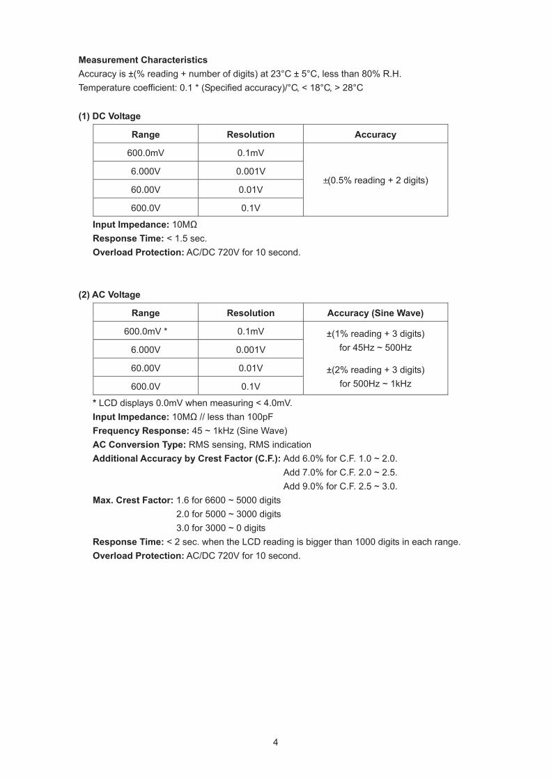
Measurement Characteristics Accuracy is ±(% reading + number of digits) at 23°C ± 5°C, less than 80% R.H. Temperature coefficient: 0.1 * (Specified accuracy)/°C, < 18°C, > 28°C (1) DC Voltage
Range Resolution Accuracy
600.0mV 0.1mV
6.000V 0.001V
60.00V 0.01V
600.0V 0.1V
±(0.5% reading + 2 digits)
Input Impedance: 10MΩ Response Time: < 1.5 sec. Overload Protection: AC/DC 720V for 10 second.
(2) AC Voltage
Range Resolution Accuracy (Sine Wave)
600.0mV * 0.1mV
6.000V 0.001V
60.00V 0.01V
600.0V 0.1V
±(1% reading + 3 digits) for 45Hz ~ 500Hz
±(2% reading + 3 digits) for 500Hz ~ 1kHz
* LCD displays 0.0mV when measuring < 4.0mV. Input Impedance: 10MΩ // less than 100pF Frequency Response: 45 ~ 1kHz (Sine Wave) AC Conversion Type: RMS sensing, RMS indication Additional Accuracy by Crest Factor (C.F.): Add 6.0% for C.F. 1.0 ~ 2.0.
Add 7.0% for C.F. 2.0 ~ 2.5. Add 9.0% for C.F. 2.5 ~ 3.0.
Max. Crest Factor: 1.6 for 6600 ~ 5000 digits 2.0 for 5000 ~ 3000 digits 3.0 for 3000 ~ 0 digits
Response Time: < 2 sec. when the LCD reading is bigger than 1000 digits in each range. Overload Protection: AC/DC 720V for 10 second.
5
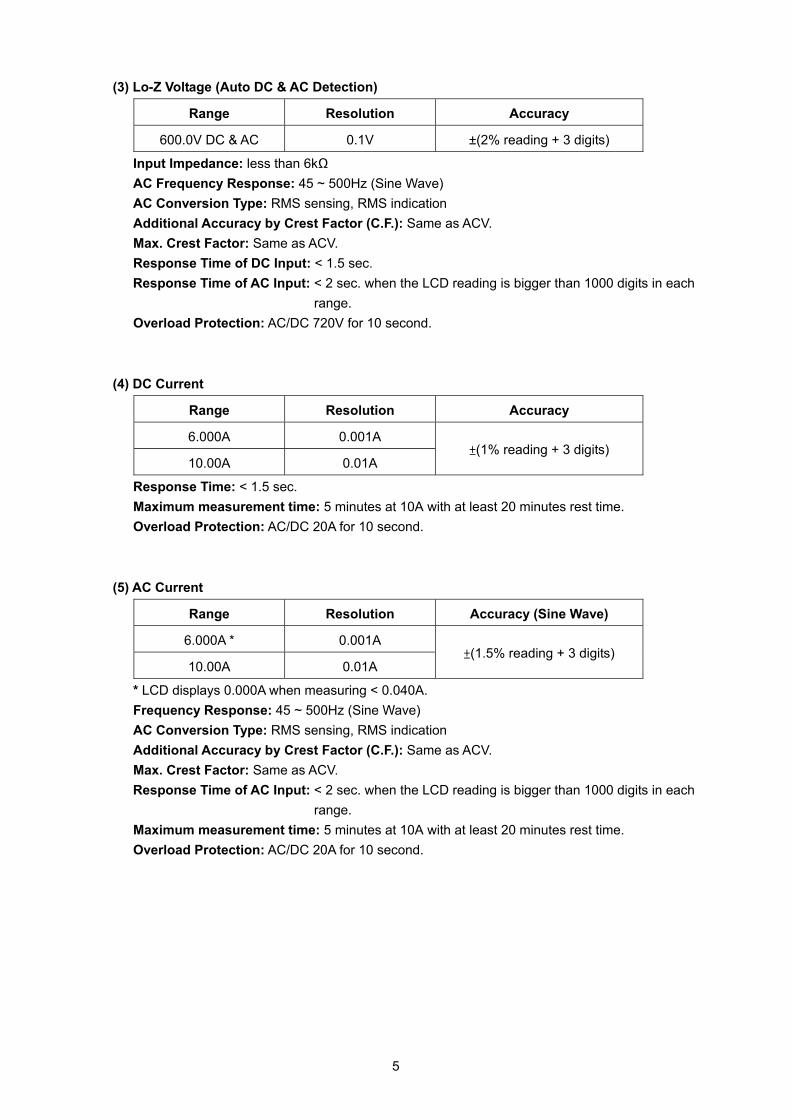
(3) Lo-Z Voltage (Auto DC & AC Detection)
Range Resolution Accuracy
600.0V DC & AC 0.1V ±(2% reading + 3 digits)
Input Impedance: less than 6kΩ AC Frequency Response: 45 ~ 500Hz (Sine Wave) AC Conversion Type: RMS sensing, RMS indication Additional Accuracy by Crest Factor (C.F.): Same as ACV. Max. Crest Factor: Same as ACV. Response Time of DC Input: < 1.5 sec. Response Time of AC Input: < 2 sec. when the LCD reading is bigger than 1000 digits in each
range. Overload Protection: AC/DC 720V for 10 second.
(4) DC Current
Range Resolution Accuracy
6.000A 0.001A
10.00A 0.01A ±(1% reading + 3 digits)
Response Time: < 1.5 sec. Maximum measurement time: 5 minutes at 10A with at least 20 minutes rest time. Overload Protection: AC/DC 20A for 10 second.
(5) AC Current
Range Resolution Accuracy (Sine Wave)
6.000A * 0.001A
10.00A 0.01A ±(1.5% reading + 3 digits)
* LCD displays 0.000A when measuring < 0.040A. Frequency Response: 45 ~ 500Hz (Sine Wave) AC Conversion Type: RMS sensing, RMS indication Additional Accuracy by Crest Factor (C.F.): Same as ACV. Max. Crest Factor: Same as ACV. Response Time of AC Input: < 2 sec. when the LCD reading is bigger than 1000 digits in each
range. Maximum measurement time: 5 minutes at 10A with at least 20 minutes rest time. Overload Protection: AC/DC 20A for 10 second.
6
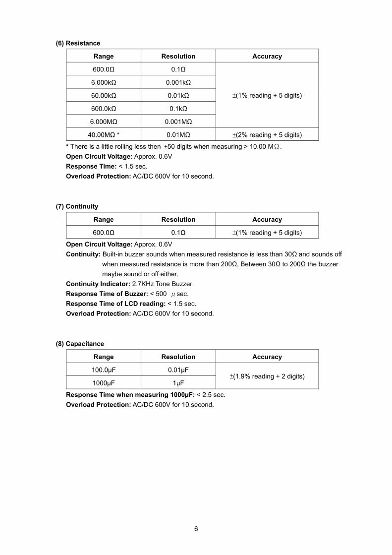
(6) Resistance
Range Resolution Accuracy
600.0Ω 0.1Ω
6.000kΩ 0.001kΩ
60.00kΩ 0.01kΩ
600.0kΩ 0.1kΩ
6.000MΩ 0.001MΩ
±(1% reading + 5 digits)
40.00MΩ * 0.01MΩ ±(2% reading + 5 digits)
* There is a little rolling less then ±50 digits when measuring > 10.00 MΩ. Open Circuit Voltage: Approx. 0.6V Response Time: < 1.5 sec. Overload Protection: AC/DC 600V for 10 second.
(7) Continuity
Range Resolution Accuracy
600.0Ω 0.1Ω ±(1% reading + 5 digits)
Open Circuit Voltage: Approx. 0.6V Continuity: Built-in buzzer sounds when measured resistance is less than 30Ω and sounds off
when measured resistance is more than 200Ω, Between 30Ω to 200Ω the buzzer maybe sound or off either.
Continuity Indicator: 2.7KHz Tone Buzzer Response Time of Buzzer: < 500 μsec. Response Time of LCD reading: < 1.5 sec. Overload Protection: AC/DC 600V for 10 second.
(8) Capacitance
Range Resolution Accuracy
100.0µF 0.01µF
1000µF 1µF ±(1.9% reading + 2 digits)
Response Time when measuring 1000µF: < 2.5 sec. Overload Protection: AC/DC 600V for 10 second.
7
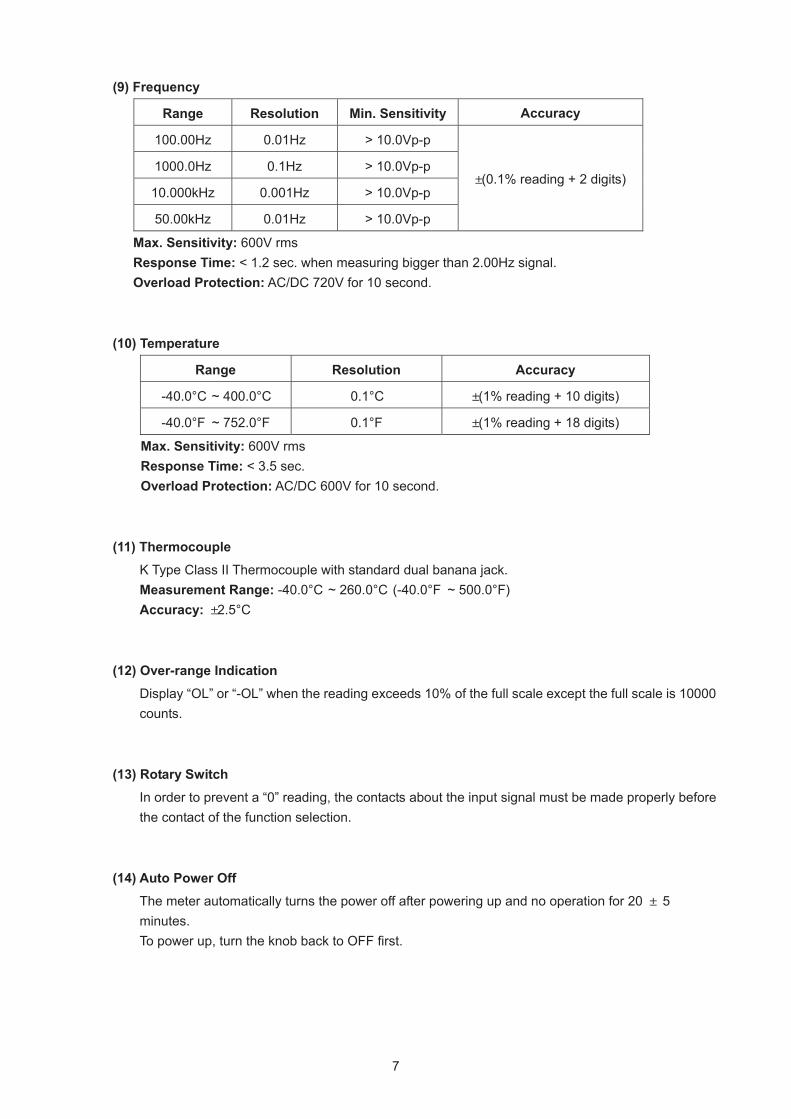
(9) Frequency
Range Resolution Min. Sensitivity Accuracy
100.00Hz 0.01Hz > 10.0Vp-p
1000.0Hz 0.1Hz > 10.0Vp-p
10.000kHz 0.001Hz > 10.0Vp-p
50.00kHz 0.01Hz > 10.0Vp-p
±(0.1% reading + 2 digits)
Max. Sensitivity: 600V rms Response Time: < 1.2 sec. when measuring bigger than 2.00Hz signal. Overload Protection: AC/DC 720V for 10 second.
(10) Temperature
Range Resolution Accuracy
-40.0°C ~ 400.0°C 0.1°C ±(1% reading + 10 digits)
-40.0°F ~ 752.0°F 0.1°F ±(1% reading + 18 digits)
Max. Sensitivity: 600V rms Response Time: < 3.5 sec. Overload Protection: AC/DC 600V for 10 second.
(11) Thermocouple
K Type Class II Thermocouple with standard dual banana jack. Measurement Range: -40.0°C ~ 260.0°C (-40.0°F ~ 500.0°F) Accuracy: ±2.5°C
(12) Over-range Indication
Display “OL” or “-OL” when the reading exceeds 10% of the full scale except the full scale is 10000 counts.
(13) Rotary Switch
In order to prevent a “0” reading, the contacts about the input signal must be made properly before the contact of the function selection.
(14) Auto Power Off
The meter automatically turns the power off after powering up and no operation for 20 ± 5 minutes. To power up, turn the knob back to OFF first.
8
(15) Measuring Rate: 3 times/sec. (16) Fuse: 10A/600V Fast Action Fuse (Cat. No. 22-89-0300) (17) Battery: Alkaline 1.5V Battery * 2 (18) Low Battery Voltage: 2.3V ± 0.1V
(19) Backlight
The meter automatically turns the backlight off after lighting up and no operation for 10 ± 1 minutes.
(20) Battery life (ALKALINE):
Approx. 26 hours with backlight on. Approx. 360 hours with backlight off.
(21) Overvoltage Category
IEC 61010-1 600V CAT. III (22) Operating Temperature
-10°C ~ 30°C, 80%RH 30°C ~ 40°C, 75%RH 40°C ~ 50°C, 45%RH
(23) Storage Temperature
-40°C ~ +60°C, 0 ~ 80%RH (No batteries)
<=<=<=
9
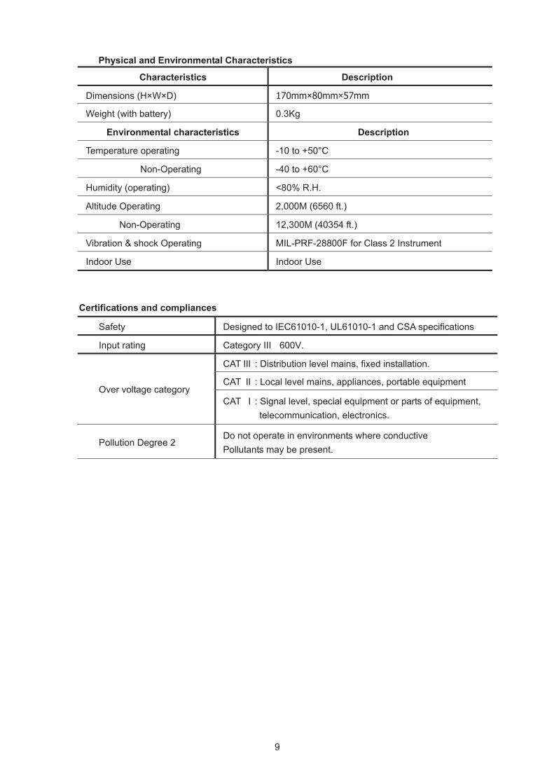
Physical and Environmental Characteristics
noitpircseD scitsiretcarahC
Dimensions (H×W×D) 170mm×80mm×57mm
gK3.0 )yrettab htiw( thgieW
noitpircseD scitsiretcarahc latnemnorivnE
C°05+ ot 01- gnitarepo erutarepmeT
Non-Operating -40 to +60°C
.H.R %08< )gnitarepo( ytidimuH
).tf 0656( M000,2 gnitarepO edutitlA
Non-Operating 12,300M (40354 ft.)
Vibration & shock Operating MIL-PRF-28800F for Class 2 Instrument
esU roodnI esU roodnI
Certifications and compliances
Safety Designed to IEC61010-1, UL61010-1 and CSA specifications
Input rating Category III 600V.
CAT III : Distribution level mains, fixed installation.
CAT II : Local level mains, appliances, portable equipment Over voltage category
CAT I : Signal level, special equipment or parts of equipment, telecommunication, electronics.
Pollution Degree 2 Do not operate in environments where conductive Pollutants may be present.
10
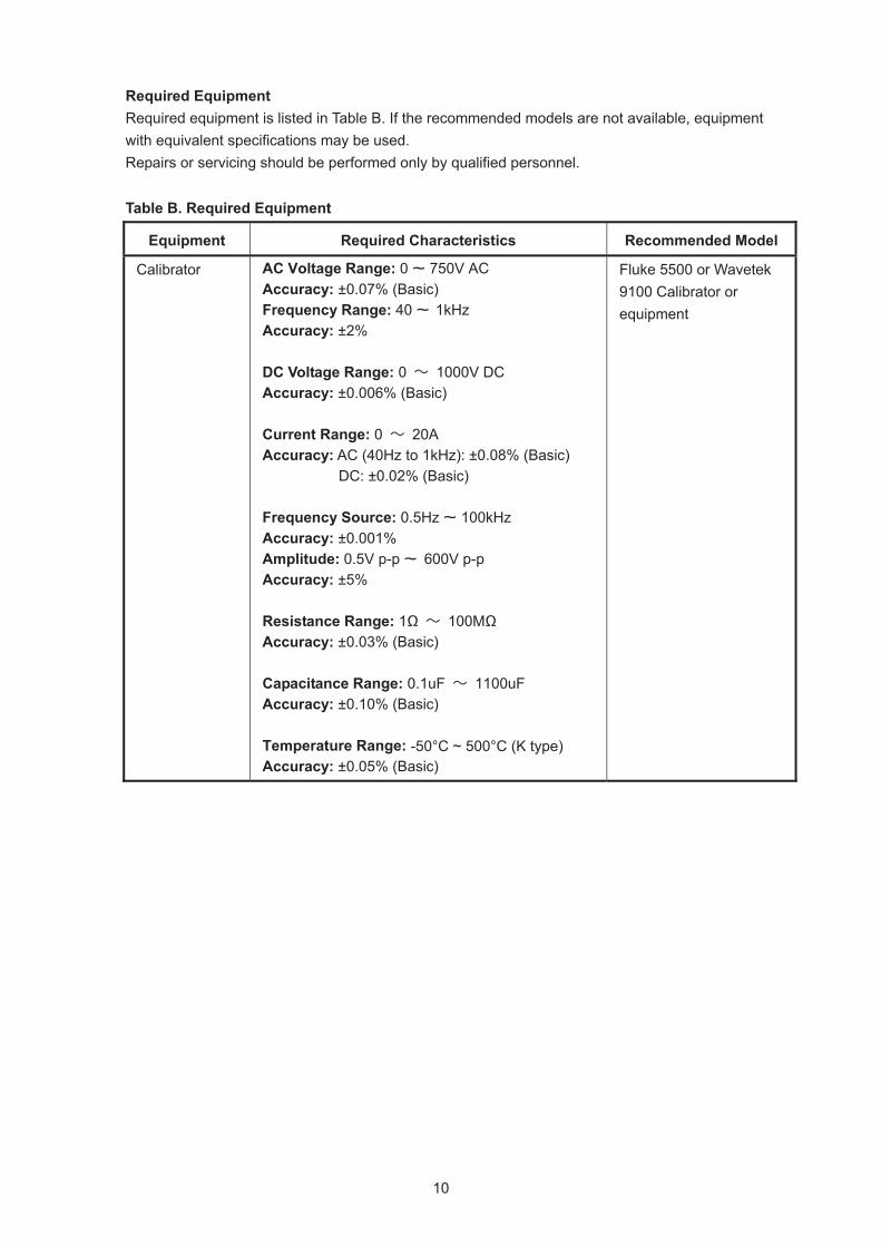
Required Equipment Required equipment is listed in Table B. If the recommended models are not available, equipment with equivalent specifications may be used. Repairs or servicing should be performed only by qualified personnel. Table B. Required Equipment
Equipment Required Characteristics Recommended Model
Calibrator AC Voltage Range: 0 ~ 750V AC Accuracy: ±0.07% (Basic) Frequency Range: 40 ~ 1kHz Accuracy: ±2% DC Voltage Range: 0 ~ 1000V DC Accuracy: ±0.006% (Basic) Current Range: 0 ~ 20A Accuracy: AC (40Hz to 1kHz): ±0.08% (Basic)
DC: ±0.02% (Basic) Frequency Source: 0.5Hz ~ 100kHz Accuracy: ±0.001% Amplitude: 0.5V p-p ~ 600V p-p Accuracy: ±5% Resistance Range: 1Ω ~ 100MΩ Accuracy: ±0.03% (Basic) Capacitance Range: 0.1uF ~ 1100uF Accuracy: ±0.10% (Basic) Temperature Range: -50°C ~ 500°C (K type) Accuracy: ±0.05% (Basic)
Fluke 5500 or Wavetek 9100 Calibrator or equipment
11
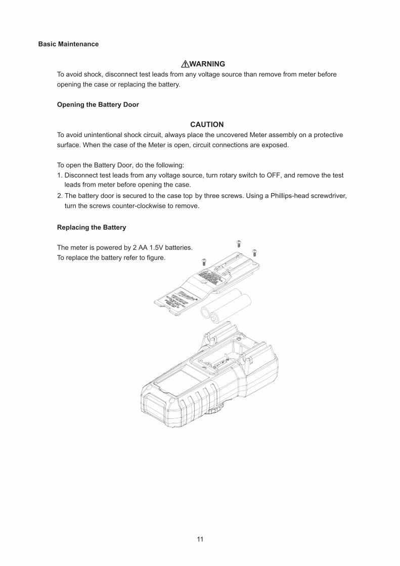
Basic Maintenance
WARNINGTo avoid shock, disconnect test leads from any voltage source than remove from meter before opening the case or replacing the battery.
Opening the Battery Door
CAUTION
To avoid unintentional shock circuit, always place the uncovered Meter assembly on a protective surface. When the case of the Meter is open, circuit connections are exposed. To open the Battery Door, do the following: 1. Disconnect test leads from any voltage source, turn rotary switch to OFF, and remove the test leads from meter before opening the case.
Replacing the Battery
The meter is powered by 2 AA 1.5V batteries. To replace the battery refer to figure.
2. The battery door is secured to the case top by three screws. Using a Phillips-head screwdriver, turn the screws counter-clockwise to remove.
input terminal, and touch the probe to the A input terminal. The display should indicate between 0.0 to 0.2 . (Bussmann KTK-10 recommended). If display reads higher than 0.2 , replace the fuse.
12
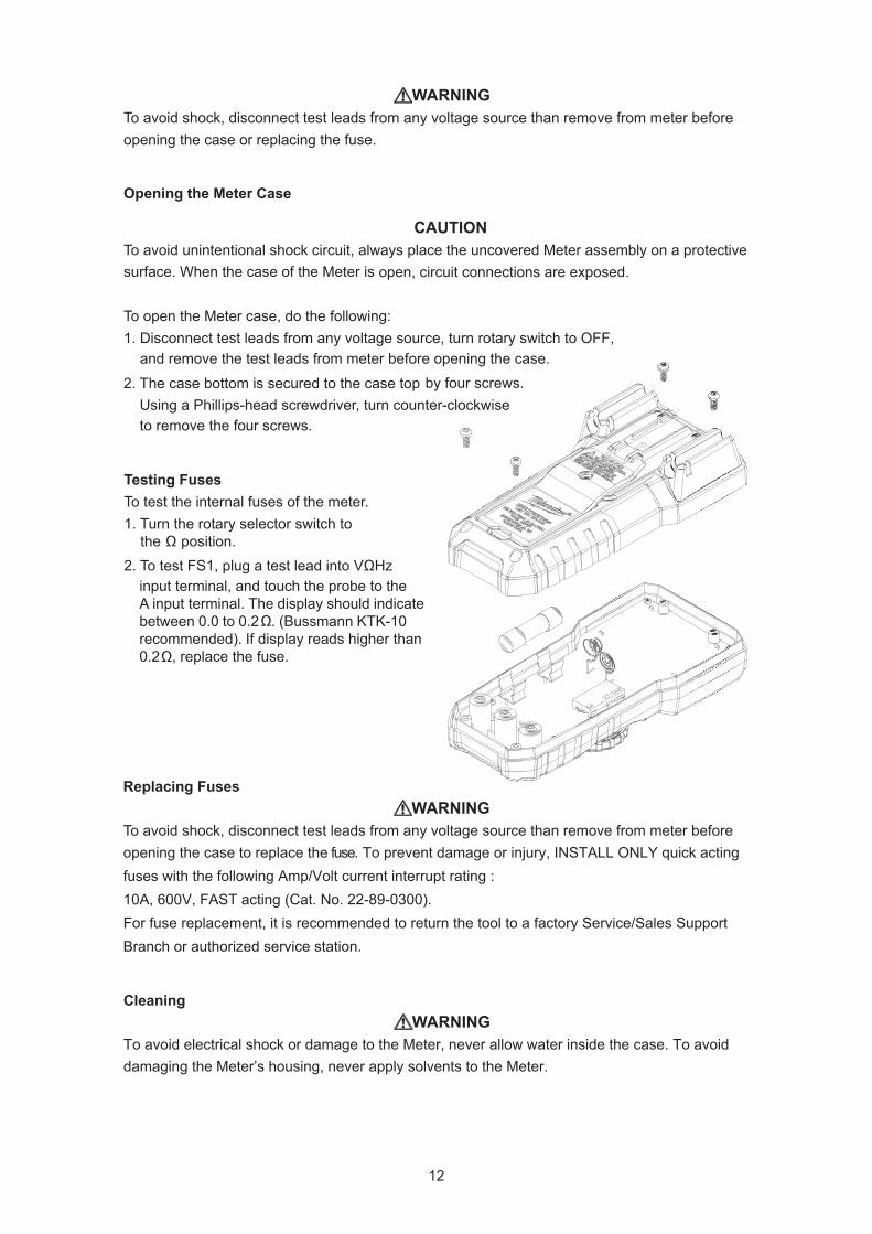
Testing Fuses To test the internal fuses of the meter. 1. Turn the rotary selector switch to the position. Ω
2. To test FS1, plug a test lead into VΩHz
Ω
Ω
Replacing Fuses
Cleaning
To avoid electrical shock or damage to the Meter, never allow water inside the case. To avoid damaging the Meter’s housing, never apply solvents to the Meter.
WARNINGTo avoid shock, disconnect test leads from any voltage source than remove from meter before opening the case to replace the fuse. To prevent damage or injury, INSTALL ONLY quick acting fuses with the following Amp/Volt current interrupt rating : 10A, 600V, FAST acting (Cat. No. 22-89-0300). For fuse replacement, it is recommended to return the tool to a factory Service/Sales Support Branch or authorized service station.
WARNING
WARNINGTo avoid shock, disconnect test leads from any voltage source than remove from meter before opening the case or replacing the fuse.
Opening the Meter Case
CAUTIONTo avoid unintentional shock circuit, always place the uncovered Meter assembly on a protective surface. When the case of the Meter is open, circuit connections are exposed.
To open the Meter case, do the following: 1. Disconnect test leads from any voltage source, turn rotary switch to OFF, and remove the test leads from meter before opening the case.
2. The case bottom is secured to the case top by four screws.
Using a Phillips-head screwdriver, turn counter-clockwiseto remove the four screws.
13
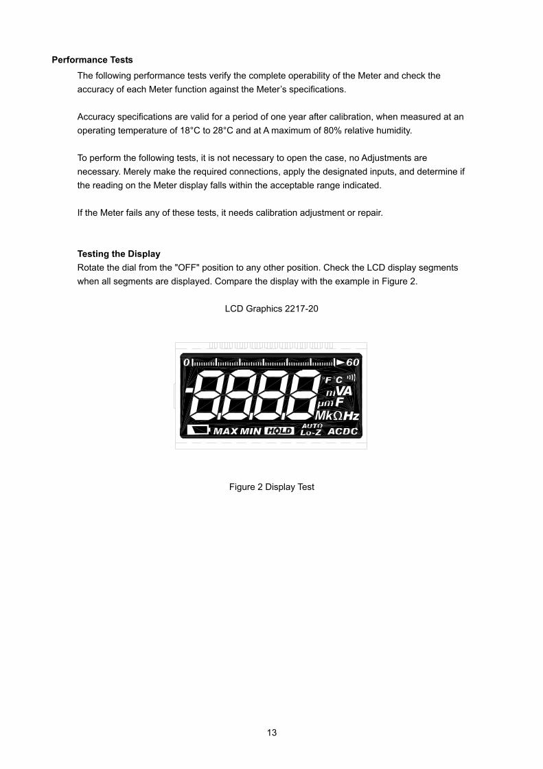
Performance Tests The following performance tests verify the complete operability of the Meter and check the accuracy of each Meter function against the Meter’s specifications. Accuracy specifications are valid for a period of one year after calibration, when measured at an operating temperature of 18°C to 28°C and at A maximum of 80% relative humidity. To perform the following tests, it is not necessary to open the case, no Adjustments are necessary. Merely make the required connections, apply the designated inputs, and determine if the reading on the Meter display falls within the acceptable range indicated. If the Meter fails any of these tests, it needs calibration adjustment or repair. Testing the Display Rotate the dial from the "OFF" position to any other position. Check the LCD display segments when all segments are displayed. Compare the display with the example in Figure 2.
LCD Graphics 2217-20
Figure 2 Display Test
14
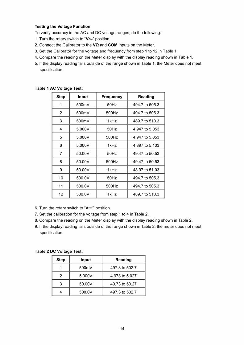
Testing the Voltage Function To verify accuracy in the AC and DC voltage ranges, do the following: 1. Turn the rotary switch to “V ” position. 2. Connect the Calibrator to the VΩ and COM inputs on the Meter. 3. Set the Calibrator for the voltage and frequency from step 1 to 12 in Table 1. 4. Compare the reading on the Meter display with the display reading shown in Table 1. 5. If the display reading falls outside of the range shown in Table 1, the Meter does not meet
specification. Table 1 AC Voltage Test:
Step Input Frequency Reading
1 500mV 50Hz 494.7 to 505.3
2 500mV 500Hz 494.7 to 505.3
3 500mV 1kHz 489.7 to 510.3
4 5.000V 50Hz 4.947 to 5.053
5 5.000V 500Hz 4.947 to 5.053
6 5.000V 1kHz 4.897 to 5.103
7 50.00V 50Hz 49.47 to 50.53
8 50.00V 500Hz 49.47 to 50.53
9 50.00V 1kHz 48.97 to 51.03
10 500.0V 50Hz 494.7 to 505.3
11 500.0V 500Hz 494.7 to 505.3
12 500.0V 1kHz 489.7 to 510.3
6. Turn the rotary switch to “V '” position. 7. Set the calibration for the voltage from step 1 to 4 in Table 2. 8. Compare the reading on the Meter display with the display reading shown in Table 2. 9. If the display reading falls outside of the range shown in Table 2, the meter does not meet
specification. Table 2 DC Voltage Test:
Step Input Reading
1 500mV 497.3 to 502.7
2 5.000V 4.973 to 5.027
3 50.00V 49.73 to 50.27
4 500.0V 497.3 to 502.7
15
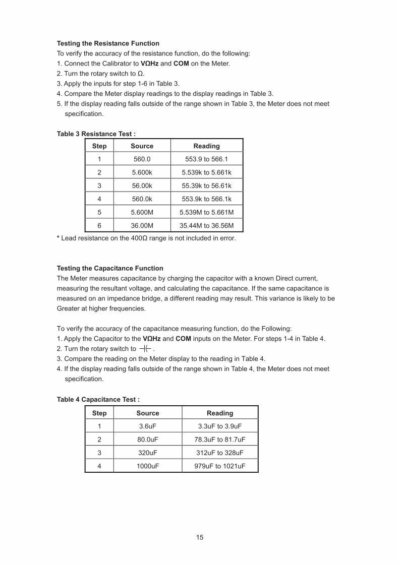
Testing the Resistance Function To verify the accuracy of the resistance function, do the following: 1. Connect the Calibrator to VΩHz and COM on the Meter. 2. Turn the rotary switch to Ω. 3. Apply the inputs for step 1-6 in Table 3. 4. Compare the Meter display readings to the display readings in Table 3. 5. If the display reading falls outside of the range shown in Table 3, the Meter does not meet
specification.
Table 3 Resistance Test :
Step Source Reading
1 560.0 553.9 to 566.1
2 5.600k 5.539k to 5.661k
3 56.00k 55.39k to 56.61k
4 560.0k 553.9k to 566.1k
5 5.600M 5.539M to 5.661M
6 36.00M 35.44M to 36.56M
* Lead resistance on the 400Ω range is not included in error. Testing the Capacitance Function The Meter measures capacitance by charging the capacitor with a known Direct current, measuring the resultant voltage, and calculating the capacitance. If the same capacitance is measured on an impedance bridge, a different reading may result. This variance is likely to be Greater at higher frequencies. To verify the accuracy of the capacitance measuring function, do the Following: 1. Apply the Capacitor to the VΩHz and COM inputs on the Meter. For steps 1-4 in Table 4. 2. Turn the rotary switch to . 3. Compare the reading on the Meter display to the reading in Table 4. 4. If the display reading falls outside of the range shown in Table 4, the Meter does not meet
specification. Table 4 Capacitance Test :
Step Source Reading
1 3.6uF 3.3uF to 3.9uF
2 80.0uF 78.3uF to 81.7uF
3 320uF 312uF to 328uF
4 1000uF 979uF to 1021uF
16
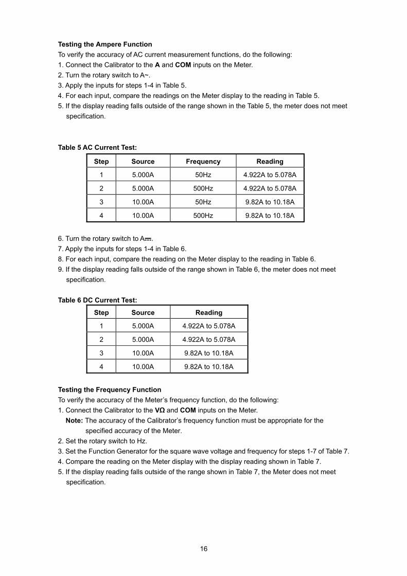
Testing the Ampere Function To verify the accuracy of AC current measurement functions, do the following: 1. Connect the Calibrator to the A and COM inputs on the Meter. 2. Turn the rotary switch to A~. 3. Apply the inputs for steps 1-4 in Table 5. 4. For each input, compare the readings on the Meter display to the reading in Table 5. 5. If the display reading falls outside of the range shown in the Table 5, the meter does not meet
specification. Table 5 AC Current Test:
Step Source Frequency Reading
1 5.000A 50Hz 4.922A to 5.078A
2 5.000A 500Hz 4.922A to 5.078A
3 10.00A 50Hz 9.82A to 10.18A
4 10.00A 500Hz 9.82A to 10.18A
6. Turn the rotary switch to A . 7. Apply the inputs for steps 1-4 in Table 6. 8. For each input, compare the reading on the Meter display to the reading in Table 6. 9. If the display reading falls outside of the range shown in Table 6, the meter does not meet
specification. Table 6 DC Current Test:
Step Source Reading
1 5.000A 4.922A to 5.078A
2 5.000A 4.922A to 5.078A
3 10.00A 9.82A to 10.18A
4 10.00A 9.82A to 10.18A
Testing the Frequency Function To verify the accuracy of the Meter’s frequency function, do the following: 1. Connect the Calibrator to the VΩ and COM inputs on the Meter.
Note: The accuracy of the Calibrator’s frequency function must be appropriate for the specified accuracy of the Meter.
2. Set the rotary switch to Hz. 3. Set the Function Generator for the square wave voltage and frequency for steps 1-7 of Table 7. 4. Compare the reading on the Meter display with the display reading shown in Table 7. 5. If the display reading falls outside of the range shown in Table 7, the Meter does not meet
specification.
17
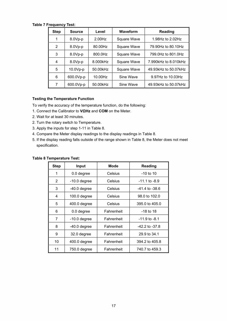
Table 7 Frequency Test:
Step Source Level Waveform Reading
1 8.0Vp-p 2.00Hz Square Wave 1.98Hz to 2.02Hz
2 8.0Vp-p 80.00Hz Square Wave 79.90Hz to 80.10Hz
3 8.0Vp-p 800.0Hz Square Wave 799.0Hz to 801.0Hz
4 8.0Vp-p 8.000kHz Square Wave 7.990kHz to 8.010kHz
5 10.0Vp-p 50.00kHz Square Wave 49.93kHz to 50.07kHz
6 600.0Vp-p 10.00Hz Sine Wave 9.97Hz to 10.03Hz
7 600.0Vp-p 50.00kHz Sine Wave 49.93kHz to 50.07kHz
Testing the Temperature Function To verify the accuracy of the temperature function, do the following: 1. Connect the Calibrator to VΩHz and COM on the Meter. 2. Wait for at least 30 minutes. 2. Turn the rotary switch to Temperature. 3. Apply the inputs for step 1-11 in Table 8. 4. Compare the Meter display readings to the display readings in Table 8. 5. If the display reading falls outside of the range shown in Table 8, the Meter does not meet
specification.
Table 8 Temperature Test:
Step Input Mode Reading
1 0.0 degree Celsius -10 to 10
2 -10.0 degree Celsius -11.1 to -8.9
3 -40.0 degree Celsius -41.4 to -38.6
4 100.0 degree Celsius 98.0 to 102.0
5 400.0 degree Celsius 395.0 to 405.0
6 0.0 degree Fahrenheit -18 to 18
7 -10.0 degree Fahrenheit -11.9 to -8.1
8 -40.0 degree Fahrenheit -42.2 to -37.8
9 32.0 degree Fahrenheit 29.9 to 34.1
10 400.0 degree Fahrenheit 394.2 to 405.8
11 750.0 degree Fahrenheit 740.7 to 459.3
d disconnect the meter from the calibrator.
18
Calibration Procedure Recalibrate the meter: It is recommended that the meter may be calibrated once year. Use the following procedure to calibrate
Environmental Condition Perform calibration at an ambient temperature and relative humidity (23°C±2°C and R.H. < 80%). Allow the instrument to sit at this temperature for at least thirty minutes.
Calibration Procedure
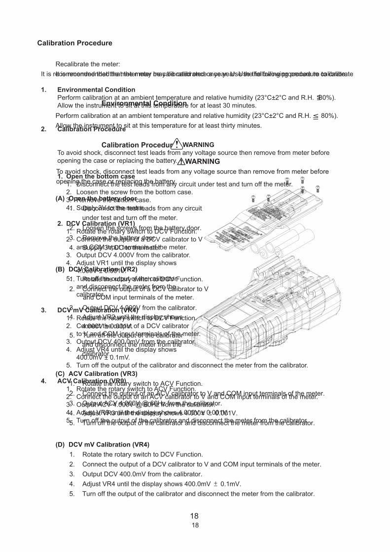
(A) Open the battery door1. Disconnect the test leads from any circuit
2. Loosen the screws from the battery door. 3. Remove the battery door. 4. Supply 3V DC to the meter.
(B) DCV Calibration (VR2) 1. Rotate the rotary switch to DCV Function. 2. Connect the output of a DCV calibrator to V
(C) ACV Calibration (VR3) 1. Rotate the rotary switch to ACV Function. 2. Connect the output of an ACV calibrator to V and COM input terminals of the meter. 3. Output ACV 4.000V @ 60Hz from the calibrator. 4. Adjust VR3 until the display shows 4.000V ± 0.001V. 5. Turn off the output of the calibrator and disconnect the meter from the calibrator.
(D) DCV mV Calibration (VR4) 1. Rotate the rotary switch to DCV Function. 2. Connect the output of a DCV calibrator to V and COM input terminals of the meter. 3. Output DCV 400.0mV from the calibrator. 4. Adjust VR4 until the display shows 400.0mV ± 0.1mV. 5. Turn off the output of the calibrator an
=
WARNINGTo avoid shock, disconnect test leads from any voltage source than remove from meter beforeopening the case or replacing the battery.
under test and turn off the meter.
and COM input terminals of the meter. 3. Output DCV 4.000V from the calibrator.4. Adjust VR2 until the display shows 4.000V ± 0.001V.5. Turn off the output of the calibrator and disconnect the meter from the calibrator.
It is recommended that the meter may be calibrated once a year. Use the following procedure to calibrate.
1. Environmental Condition Perform calibration at an ambient temperature and relative humidity (23°C±2°C and R.H. 80%). Allow the instrument to sit at this temperature for at least 30 minutes.
2. Calibration Procedure
WARNING To avoid shock, disconnect test leads from any voltage source then remove from meter before opening the case or replacing the battery.
1. Open the bottom case 1. Disconnect the test leads from any circuit under test and turn off the meter. 2. Loosen the screw from the bottom case. 3. Remove the bottom case. 4. Supply 3V to the meter.
2. DCV Calibration (VR1) 1. Rotate the rotary switch to DCV Function. 2. Connect the output of a DCV calibrator to V and COM input terminals of the meter. 3. Output DCV 4.000V from the calibrator. 4. Adjust VR1 until the display shows 4.000V ± 0.001V. 5. Turn off the output of the calibrator and disconnect the meter from the calibrator.
3. DCV mV Calibration (VR4) 1. Rotate the rotary switch to DCV Function. 2. Connect the output of a DCV calibrator to V and COM input terminals of the meter. 3. Output DCV 400.0mV from the calibrator. 4. Adjust VR4 until the display shows 400.0mV ± 0.1mV. 5. Turn off the output of the calibrator and disconnect the meter from the calibrator.
4. ACV Calibration (VR9) 1. Rotate the rotary switch to ACV Function. 2. Connect the output of an ACV calibrator to V and COM input terminals of the meter. 3. Output ACV 4.000V @ 60Hz from the calibrator. 4. Adjust VR9 until the display shows 4.000V ± 0.001V. 5. Turn off the output of the calibrator and disconnect the meter from the calibrator.
<=
18
5. Resistance (6kΩ Range) Calibration (VR10) 1. Rotate the rotary switch to the resistance function. 2. Connect the output of a resistance calibrator to V and COM input terminals of the meter. 3. Output resistance 5.000kΩ from the calibrator. 4. Adjust the VR10 until the display shows 5.000kΩ ± 1Ω. 5. Turn off the output of the calibrator and disconnect the meter from the calibrator.
6. Capacitance Calibration (VR11) 1. Rotate the rotary switch to Capacitance Function. 2. Connect the output of a capacitance calibrator to V and COM input terminals of the meter. 3. Output capacitance 96.0μF from the calibrator. 4. Adjust VR11 until the display shows 96.0μF ± 0.1μF. 5. Turn off the output of the calibrator and disconnect the meter from the calibrator.
7. DCA mA Calibration (VR5、VR6) 1. Rotate the rotary switch to DCA Function. 2. Connect the output of a DCA calibrator to A and COM input terminals of the meter. 3. Output DCA 50.00mA from the calibrator. 4. Adjust VR6 until the display shows 50.00mA ± 0.01mA. 5. Output DCA 500.0mA from the calibrator. 6. Adjust VR5 until the display shows 500.0mA ± 0.1mA. 7. Turn off the output of the calibrator and disconnect the meter from the calibrator.
8. DCA Calibration (VR12) 1. Rotate the rotary switch to DCA Function. 2. Connect the output of a DCA calibrator to A and COM input terminals of the meter. 3. Output DCA 5.000A from the calibrator. 4. Adjust VR12 until the display shows 5.000A ± 0.001A. 5. Turn off the output of the calibrator and disconnect the meter from the calibrator.
9. Temperature Calibration (VR2, VR7) 1. Rotate the rotary switch to Temperature Function. 2. Short the two pads of JP1 on the PCB. 3. Switch the temperature scale to the Celsius scale. 4. Connect the output of a DCV calibrator to V and COM input terminals of the meter. 5. Output DCV 12.209mV from the calibrator. 6. Adjust VR7 until the display shows 300.0°C ± 0.1°C. 7. Disconnect the calibrator. 8. Open the two pads of JP1 on the PCB. 9. Connect the thermocouple calibrator via the adapter to V and COM input terminals of the meter, and wait at least 30 minutes to make sure the input terminals of the meter and the calibrator are heat balance. 10. Output 0.0°C from the temperature calibrator. 11. Adjust VR2 until the display shows 0.0°C ± 0.1°C. 12. Turn off the output of the calibrator and disconnect the meter from the calibrator.
10. Assemble the bottom case 1. Assemble the bottom case. 2. Tighten the screw.
19