rep design llc
TRANSCRIPT

Instructions: AMB-BKT-Mast-D2.0©
Page 1 of 4Version: 20110107
REP Design LLCSouthington, CT 06489 860.426.1894 [email protected] www.repDesign.us
INSTALLATION INSTRUCTIONS:
AMB-BKT-Mast-D2.0© Super Heavy Duty "L" Antenna Bracket for Antenna Masts
Thank you for your purchase, we appreciate your business and interest in our products.
These instructions describe how to install the AMB-BKT-Mast-D2.0© (“BKT”) "L" bracket for small to large mobileHF/V/UHF antennas, for mounting to the top of masts with outside diameters from 1-1/4 to 2 inches. It can supportessentially any mobile antenna and even L-A-R-G-E screwdriver or motorized HF antennas! These instructions alsodescribe and illustrate how to install our various options, which even allow you to install up to THREE (3) antennas!
Antennas are mounted into the ¾”diameter hole using your antenna bolt and insulating washers, your base or one of ourseveral interchangeable antenna bases.
Specifications: Buffed 6061 aluminum "L" bracket, 1/2 inch thick x 8 x 8x 4 inches wide –five powder coat colors optional. 18-8 stainless steel hardware: 3/8x16 mounting bolts, 1/4x20 ground point with wing nut. Two (2) ¼”bolts (18-8 stainless steel) with heavy-duty solder lugs (16-12 gauge wire) for attaching counterpoise
wires and to attach the optional “AMB-Arm2”second antenna arm (one or two will fit) and SHUNT-100. Three (3) 304 stainless steel U-bolts for attaching the BKT to any mast from 1-1/4 to 2”diameter. ¾”diameter hole for antenna mounting (panel thickness ½”). 3/8”hole for mounting the optional AMB-Gnd-8W counterpoise ring which fits up to eight whips or “ham sticks”
to form a horizontal counterpoise.
The photos below show what you get standard, with dimensions. Options are listed later in these instructions.

Instructions: AMB-BKT-Mast-D2.0©
Page 2 of 4Version: 20110107
The latest version of these instructions with color photos can be found on our DOWNLOADS web page, as PDF files.
Safety First!
Be sure that your mast is strong enough and whether it needs guying to support your antenna. If you do not feel that youhave the ability to safely install the BKT, please contact us if you would like to return it (within the first two weeks, seeWarranty for details). It is up to the user to ensure that everything is installed securely and safely. These instructionsare meant to provide general guidelines but cannot provide all of the details on how to safely install your mount andantenna, as each installation is unique. As with any antenna installation, be careful around thunderstorms andlightening, and you may want to remove your antenna or disconnect the coax BEFORE a storm appears - rememberthat if you can hear thunder you can be struck by lightning! Also STAY AWAY from overhead wires! SAFETY FIRST!
Tools Needed to Install BKT and Options
No special tools are required. A wrench is needed to tighten the mounting bolts.
Installation Suggestions
The BKT bolts to the top of an antenna mast with an outside diameter from 1-1/4”to 2”, using the included three (3) 3/8inch U-bolts.
1) Before attaching the BKT to your mast, attach your antenna base (yours or one of ours) and any options (see listbelow). The two ¼”ground points can be used to attach the optional “AMB-Arm2”second antenna arm, SHUNT-100or your wire ground counterpoise. See the Options section below and the illustrated photos on the last page forillustrations on mounting.
2) Connecting a Ground Counterpoise.
a) For HF, you can use a simple wire counterpoise connected to the two (2) provided heavy-duty solder lugs on the ¼inch bolts (use 14 gauge or smaller, as even small gauge flat cable works). Use at least four or more wires that canbe cut to the band or simply use at least four 10 foot long radials which can work on 20m and above. Use longerradials for the lower bands. Our optional AMB-Gnd-8W counterpoise ring can fit up to eight 3/8x24 studtelescoping whips to form a horizontal counterpoise; whips are available (and will work) up to 12 feet long. Thecounterpoise, whichever you use, will work best if elevated ABOVE GROUND and not laid on the ground unlessyou can install MANY radials. A counterpoise even 5 or more feet above the ground works fine, but the higher thebetter. The counterpoise should be somewhat horizontal but can slope away from the antenna. A counterpoise thatis mostly vertical may not work well.
b) For V/UHF (6m and above), the counterpoise is connected to the ground point bolt near the antenna base andworks best if slightly shorter than a 1/4 wavelength. For multi band antennas, the length should be "cut" for thelowest band. This can be made from stiff wire or whip antennas or other radials sticking out from the base of theantenna. Four are recommended, and can be approximately horizontal or sloping away from the antenna up to a 45degree angle. Our "NMO radial" base does NOT require any additional radials for 2m-70cm and can be used as-isor cut for your specific band, from 135-512 MHz.
3) Attach your antenna to the base. Also attach your second/third V/UHF antenna if you installed one or two AMB-Arm2brackets. FIRST, DOUBLE CHECK to be sure that the six (6) BKT U-bolt nuts are firmly tightened and that your mastis securely mounted and its hardware is tight. Double check your mast guy wires, if installed.
4) Antenna and coax suggestions.
Coax connection. Generally, RG-58 size coax works fine for portable or fixed-base installations where the lengthof the coax is typically less than 25 feet, especially if you run under 500 watts. You can use any coax you desire.
SWR adjusting device (if needed) for HF antennas, especially those mounted near the ground, to reduce the SWRto an acceptable level at the antenna resonance point on 160m and 80m, and maybe also on 40m. You may need ashunt load inductor, UNUN, or additional capacitance to reduce the SWR. Some of these devices need to beinstalled at the antenna and if so should be weather resistant (like our SHUNT-100).
Ferrite bead filters to reduce HF antenna tuning problems and to help prevent RFI in devices connected to yourradio. For the HF bands, use Mix 31 or other types that are designed to filter the entire HF band. Do NOT use

Instructions: AMB-BKT-Mast-D2.0©
Page 3 of 4Version: 20110107
unknown ferrites as they may not work at HF frequencies! You may want to install at least 3 ferrites, closelyspaced, over your coax / antenna motor cable as close to your antenna as possible. One of these should have thecoax wound 2-3 times around one of the ferrites (improves filtering at the lower frequencies). Also install ferritesin a similar fashion on your motor/turns counter cable, and install one ferrite on the coax near your transceiver.Some installations may require 10 or more ferrites on EACH cable, at the antenna end of the cables. A white paperon this topic can be downloaded for free from our web page: http://www.repdesign.us/Download.html
Tuning an HF screwdriver / motorized antenna. You can tune your antenna using a DPDT, center off, manualswitch or one of the automatic tuning devices that powers your antenna motor and stops at the resonance point. Donot confuse these with "antenna tuners", which add capacitance / inductance to match the antenna to the radio -generally speaking these should NOT be used with "resonant" antennas except to fine tune an SWR that is slightlytoo high and can not be reduced by improved grounding, improving the ground counterpoise, installing ferritebeads or using a load inductor or other device.
Suggestions and precautions with multiple antennas. The BKT is capable of supporting up to three (3) separateantennas if you purchase two of our AMB-Arm2 brackets. You can use a duplexer/triplexer for running one lengthof coax from multiple antennas to ONE radio. If you use more than one radio with multiple antennas, use separateruns of coax and be careful not to damage the receiver of one radio while transmitting on another radio, as the RFfield is quite strong with closely space antennas. If using one radio with an HF and one or two V/UHF antenna(s)this is not a problem.
AMB-BKT-Mast-D2.0 Options
The following is a summary of the options that will fit the BKT. Illustrations of the these options are shown below and onthe last page which shows an example layout.
AMB-Gnd-8W: Ground counterpoise "ring" bracket for using up to eight (8) of your telescoping whips or tuned“hamstick”or BuddipoleTM antennas that have the standard 3/8x24 thread. Can be used in place of a simple wireground counterpoise connected to the BKT bracket ground point.
(see photos on last page)
AMB-Arm2: Second antenna bracket for mobile V/UHF antennas, with NMO base and four removable groundradials for 135-512 MHz. The BKT can fit one or two Arm2’s, for up to THREE ANTENNAs on ONE BKT!
(see photos on last page)
SHUNT-100: Adjustable weather resistant shunt load inductor for those installations that have a low impedanceon the low bands (160-40m) resulting in a high SWR, especially for antennas mounted near the ground. This is forantennas that need additional inductance. Includes a silver plated coil clip with tightening screw and tin platedsolid copper, custom wound, coil.
(see photos on last page)
Antenna bases: Our bases that will fit the BKT include NMO, NMO groundplane, SO239, VersaBase (forBuddipoleTM antennas) and SHF/WiFi panel antennas. See the last page for photos of several of ourinterchangeable antenna bases that also fit several of our other mounts and brackets. Please note that our 3/8x24heavy duty stud base will NOT FIT the BKT, due to its thickness. For mounting HF and other antennas that are
Instructions: AMB-BKT-Mast-D2.0©
Page 4 of 4Version: 20110107
attached with a 3/8x24 bolt or stud base, you can purchase a bolt and insulating washers from suppliers such as HiQ Antennas and others. The length of bolt you will need is 1-1/2 –1/3/4 inches for most antennas. You can evenmount Scorpion brand HF screwdriver antennas with their ¾”base bolt! If you need help please let us know.
Spare parts, accessories, downloads and related products.
Let us know if you need spare parts or are looking for something that we do not yet provide –your idea could become anew product! As a specialty company, we are looking for unique ideas to serve the amateur and two-way radio community.
To download a current Price List or Product Guide, go to: http://www.repdesign.us/Download3.html
Warranty Summary
All products include a two (2) week "return for any reason" and six (6) month manufacturing defects limitedwarranty. If you should need to return your product please contact us IN ADVANCE to obtain a returnauthorization number. Please refer to the complete warranty terms that are enclosed with your order; this is alsoincluded on our web site.
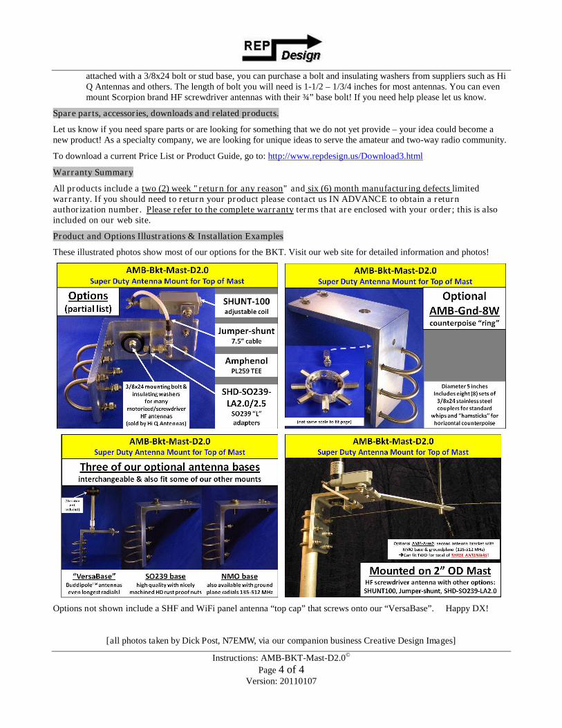
Product and Options Illustrations & Installation Examples
These illustrated photos show most of our options for the BKT. Visit our web site for detailed information and photos!
Options not shown include a SHF and WiFi panel antenna “top cap”that screws onto our “VersaBase”. Happy DX!
[all photos taken by Dick Post, N7EMW, via our companion business Creative Design Images]