rem 610 motor protection relay - library.e.abb.com · rem 610 is a versatile multifunction...
TRANSCRIPT
REM 610Motor Protection RelayTechnical Reference Manual

REM 6101MRS 752263-MUM
Issued: 25.11.2003 Version: C/09.09.2005 We reserve the right to change data without prior notice.
Motor Protection RelayTechnical Reference Manual
Contents1. Introduction ...............................................................................6
1.1. About this manual .........................................................................61.2. The use of the relay ......................................................................61.3. Features ........................................................................................61.4. Guarantee .....................................................................................81.5. Revision history .............................................................................8
2. Safety information .....................................................................93. Instructions ..............................................................................10
3.1. Application ...................................................................................103.2. Requirements ..............................................................................103.3. Configuration ...............................................................................10
4. Technical description .............................................................144.1. Functional description .................................................................14
4.1.1. Product functions .............................................................144.1.1.1. Schema of product functions ..............................144.1.1.2. Protection functions ............................................144.1.1.3. Inputs .................................................................154.1.1.4. Outputs ...............................................................154.1.1.5. Emergency start .................................................154.1.1.6. Restart inhibit .....................................................154.1.1.7. Motor start up .....................................................164.1.1.8. Rated current of the protected unit .....................164.1.1.9. Disturbance recorder ..........................................174.1.1.10.HMI ....................................................................174.1.1.11.Non-volatile memory ..........................................174.1.1.12.Self-supervision .................................................174.1.1.13.Time synchronization .........................................18
4.1.2. Measurements .................................................................194.1.3. Configuration ....................................................................204.1.4. Protection .........................................................................22
4.1.4.1. Block diagram ....................................................224.1.4.2. Thermal overload protection ..............................224.1.4.3. Start-up supervision ...........................................294.1.4.4. Short-circuit protection .......................................304.1.4.5. Undercurrent protection .....................................314.1.4.6. Earth-fault protection ..........................................314.1.4.7. Unbalance protection .........................................32
©Copyright 2005 ABB Oy, Distribution Automation, Vaasa, FINLAND
1MRS 752263-MUMMotor Protection Relay
Technical Reference Manual
REM 610
4.1.4.8. Phase reversal protection .................................. 334.1.4.9. Cumulative start-up time counter ....................... 344.1.4.10.Circuit-breaker failure protection ........................ 344.1.4.11.Temperature protection (optional) ..................... 354.1.4.12.Settings .............................................................. 394.1.4.13.Technical data on protection functions .............. 50
4.1.5. Trip-circuit supervision ..................................................... 534.1.6. Indicator LEDs and operation indication messages ......... 554.1.7. Motor running time counter .............................................. 554.1.8. Monitoring of demand values .......................................... 564.1.9. Commissioning tests ........................................................ 564.1.10.Disturbance recorder ....................................................... 56
4.1.10.1.Function ............................................................. 564.1.10.2.Disturbance recorder data ................................. 574.1.10.3.Control and indication of disturbance recorder
status ................................................................. 584.1.10.4.Triggering .......................................................... 584.1.10.5.Settings and unloading ...................................... 584.1.10.6.Event code of the disturbance recorder ............. 58
4.1.11.Recorded data of the last events ..................................... 594.1.12.Communication ports ....................................................... 614.1.13.IEC 60870-5-103 remote communication protocol .......... 624.1.14.Modbus remote communication protocol ......................... 65
4.1.14.1.Protocol overview .............................................. 654.1.14.2.Profile of Modbus REM 610 ............................... 66
4.1.15.SPA bus communication protocol parameters ................. 784.1.15.1.Event codes ....................................................... 92
4.1.16.Self-supervision (IRF) system .......................................... 964.1.16.1.Self-supervision of the RTD module .................. 97
4.1.17.Relay parameterization .................................................... 984.2. Design description ...................................................................... 98
4.2.1. Input/output connections ................................................. 984.2.2. Serial communication connections ................................ 1034.2.3. Technical data .............................................................. 107
5. Setting calculations and application examples ................. 1125.1. Setting calculations ................................................................... 112
5.1.1. Protected unit scaling factor .......................................... 1125.1.2. Thermal overload protection .......................................... 112
5.1.2.1. Selecting weighting factor p ............................. 1135.1.2.2. Safe stall time for hot starts ............................. 1155.1.2.3. Checking the set safe stall time for cold starts 118
4
1MRS 752263-MUM Motor protection Relay
Technical Reference Manual
REM 610
5.1.2.4. Checking the set safe stall time for a single start ..................................................................119
5.1.2.5. Restart inhibit level, θi .......................................1195.1.2.6. Prior alarm level, θa ..........................................1195.1.2.7. Time constant multiplier, Kc ..............................119
5.1.3. Start-up supervision .......................................................1195.1.3.1. Start-up supervision based on thermal stress
calculation ........................................................1195.1.3.2. Checking the need for speed switch ................120
5.1.4. Cumulative start-up time counter ...................................1205.1.5. Short-circuit protection ...................................................1215.1.6. Unbalance and phase reversal protection .....................121
5.1.6.1. Selecting the start value for stage I2> ..............1215.1.6.2. Selecting the time constant, K2 ........................1215.1.6.3. Connection with two phase current
transformers .....................................................1225.1.7. Earth-fault protection ......................................................122
5.1.7.1. Stabilizing virtual earth-fault currents ...............1235.1.7.2. Increasing the sensitivity of the earth-fault
protection .........................................................1235.1.8. Circuit-breaker failure protection ....................................1235.1.9. Temperature protection (optional) ..................................123
5.2. Application examples ................................................................1245.2.1. Protecting a circuit-breaker controlled motor .................1245.2.2. Protecting a motor at an ambient temperature other
than 40°C .......................................................................1255.2.3. Protecting a contactor controlled motor .........................1265.2.4. Protecting non-rotating objects ......................................1275.2.5. Earth-fault protection in an isolated or a compensated
network ..........................................................................1275.2.6. Earth-fault protection in a solidly earthed network .........127
6. Ordering information ............................................................1297. Revision history of REM 610 ................................................131
7.1. Revision identification ...............................................................1317.2. Changes and additions to the earlier released revision A .........131
8. References .............................................................................1329. Abbreviations ........................................................................13310.Check lists .........................................................................135
5
1MRS 752263-MUMMotor Protection Relay
Technical Reference Manual
REM 610
1. Introduction
1.1. About this manualThis manual provides thorough information on the protection relay REM 610 Revision B and its applications, focusing on giving a technical description of the relay. For more information about earlier revisions, refer to section Revision history.
Refer to the Operators Manual for instructions on how to use the Human-Machine Interface (HMI) of the relay, also known as the Man-Machine Interface (MMI), and to the Installation Manual for installation of the relay.
1.2. The use of the relayREM 610 is a versatile multifunction protection relay mainly designed to protect motors in a wide range of motor applications.
REM 610 is based on a microprocessor environment. A self-supervision system continuously monitors the operation of the relay.
The HMI includes a Liquid Crystal Display (LCD) which makes the local use of the relay safe and easy.
Local control of the relay via serial communication can be carried out with a computer connected to the front communication port. Remote control can be carried out via the rear connector connected to the control and monitoring system through the serial communication bus.
1.3. Features Three-phase thermal overload protection Three-phase motor start-up supervision based on thermal stress calculation with
speed switch blocking ability Three-phase overcurrent protection with definite-time characteristic and speed
switch blocking ability Three-phase short-circuit protection with instantaneous or definite-time
characteristic Three-phase undercurrent (loss of load) protection with definite-time
characteristic Non-directional earth-fault protection with definite-time characteristic Three-phase unbalance protection based on the negative-phase-sequence current
with inverse definite minimum time characteristic Phase reversal protection based on the negative-phase-sequence current Cumulative start-up time counter with restart inhibit function Circuit-breaker failure protection Temperature protection stages with definite-time characteristic Emergency start function Optional RTD module
with six measuring inputs supports PTC thermistors and various RTD sensors
6
1MRS 752263-MUM Motor protection Relay
Technical Reference Manual
REM 610
three additional galvanically isolated digital inputs Disturbance recorder
recording time up to 80 seconds triggering by one or several internal or digital input signals records four analogue channels and up to eight user-selectable digital channels adjustable sampling rate
Non-volatile memory for up to 100 event codes with time stamp setting values disturbance recorder data recorded data of the five last events with time stamp number of starts for protection stages operation indication messages and LEDs showing the status at the moment of
power failure Battery back-up for real-time clock Battery charge supervision Four accurate current inputs Two galvanically isolated digital inputs and three additional digital inputs on the
optional RTD module Time synchronization via a digital input All settings can be modified with a PC HMI with an alphanumeric LCD and manoeuvring buttons
eight programmable LEDs Detachable plug-in unit Three normally open power output contacts Trip-circuit supervision Two change-over signal output contacts Output contact functions freely configurable for desired operation Optical front communication connection: wirelessly or via cable Optional rear communication module with plastic fibre-optic, combined
fibre-optic (plastic and glass) or RS-485 connection for system communication using the SPA-bus, IEC 60870-5-103 or Modbus (RTU and ASCII) communication protocol
Continuous self-supervision of electronics and software. At an internal relay fault, all protection stages and outputs will be blocked.
User-selectable rated frequency 50/60 Hz User-selectable password protection for the HMI Display of primary current values Demand values Multi-language support
7
1MRS 752263-MUMMotor Protection Relay
Technical Reference Manual
REM 610
1.4. GuaranteePlease inquire about the terms of guarantee of your nearest ABB representative.
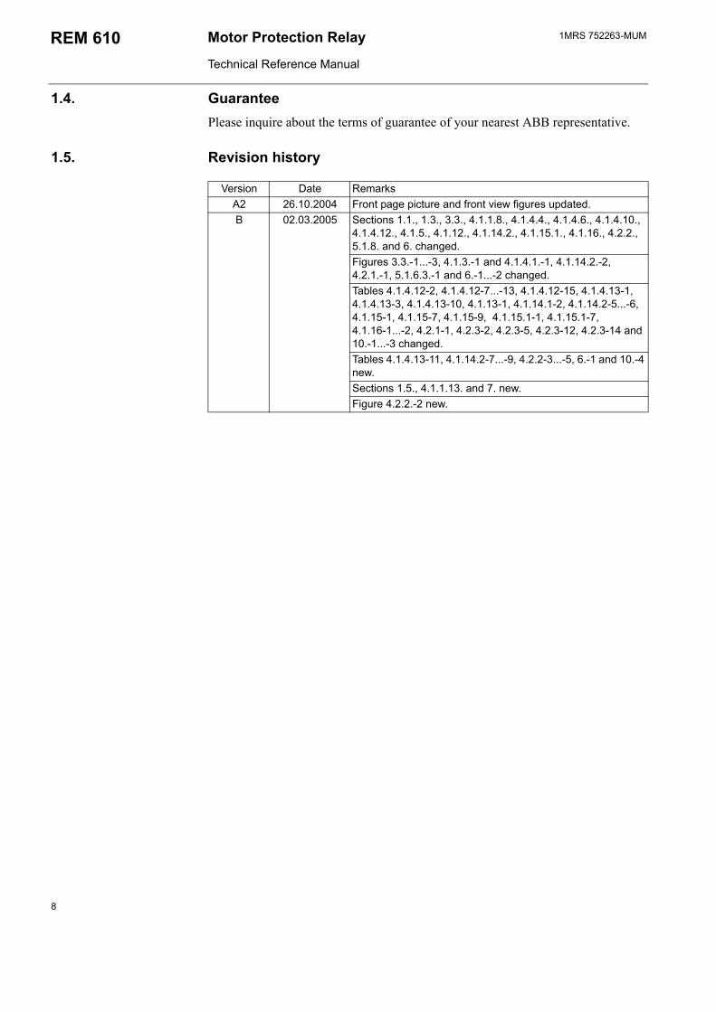
1.5. Revision history
Version Date RemarksA2 26.10.2004 Front page picture and front view figures updated.B 02.03.2005 Sections 1.1., 1.3., 3.3., 4.1.1.8., 4.1.4.4., 4.1.4.6., 4.1.4.10.,
4.1.4.12., 4.1.5., 4.1.12., 4.1.14.2., 4.1.15.1., 4.1.16., 4.2.2., 5.1.8. and 6. changed.Figures 3.3.-1...-3, 4.1.3.-1 and 4.1.4.1.-1, 4.1.14.2.-2, 4.2.1.-1, 5.1.6.3.-1 and 6.-1...-2 changed.Tables 4.1.4.12-2, 4.1.4.12-7...-13, 4.1.4.12-15, 4.1.4.13-1, 4.1.4.13-3, 4.1.4.13-10, 4.1.13-1, 4.1.14.1-2, 4.1.14.2-5...-6, 4.1.15-1, 4.1.15-7, 4.1.15-9, 4.1.15.1-1, 4.1.15.1-7, 4.1.16-1...-2, 4.2.1-1, 4.2.3-2, 4.2.3-5, 4.2.3-12, 4.2.3-14 and 10.-1...-3 changed.Tables 4.1.4.13-11, 4.1.14.2-7...-9, 4.2.2-3...-5, 6.-1 and 10.-4 new.Sections 1.5., 4.1.1.13. and 7. new.Figure 4.2.2.-2 new.
8
1MRS 752263-MUM Motor protection Relay
Technical Reference Manual
REM 610
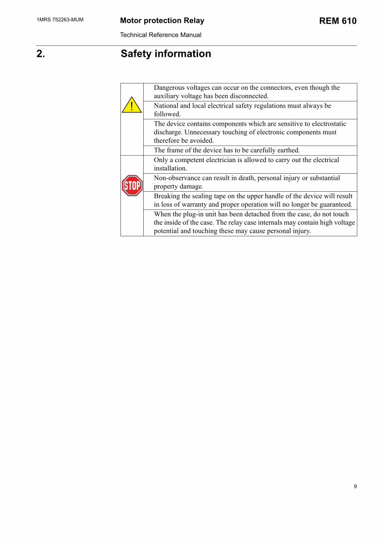
2. Safety information
Dangerous voltages can occur on the connectors, even though the auxiliary voltage has been disconnected.National and local electrical safety regulations must always be followed.The device contains components which are sensitive to electrostatic discharge. Unnecessary touching of electronic components must therefore be avoided.The frame of the device has to be carefully earthed.Only a competent electrician is allowed to carry out the electrical installation.Non-observance can result in death, personal injury or substantial property damage.Breaking the sealing tape on the upper handle of the device will result in loss of warranty and proper operation will no longer be guaranteed.When the plug-in unit has been detached from the case, do not touch the inside of the case. The relay case internals may contain high voltage potential and touching these may cause personal injury.
9
1MRS 752263-MUMMotor Protection Relay
Technical Reference Manual
REM 610
3. Instructions
3.1. ApplicationREM 610 is a versatile multifunction protection relay mainly designed for protection of standard medium and large MV asynchronous motors in a wide range of motor applications. It handles fault conditions during motor start up, normal run, idling, and cooling down at standstill, e.g. in pump, fan, mill or crusher applications.
The large number of integrated protection functions makes REM 610 a complete protection against motor damage. The relay can be used with both circuit-breaker controlled and contactor controlled drives.
REM 610 can equally well be used to protect, for instance, feeder cables and power transformers which require thermal overload protection and, for instance, single-, two- or three-phase overcurrent or non-directional earth-fault protection.
3.2. RequirementsTo secure correct and safe operation of the relay, preventive maintenance is recommended to be performed every five years when REM 610 is operating under the specified conditions; see below and section Technical data.
When being used for real-time clock or recorded data functions, the battery should be changed every five years.
Environmental conditions
Recommended temperature range (continuous) -10...+55°C Limit temperature range (short-term) -40...+70°C Temperature influence on the operation accuracy of the
protection relay within the specified service temperature range0.1%/°C
Transport and storage temperature range -40...+85°C
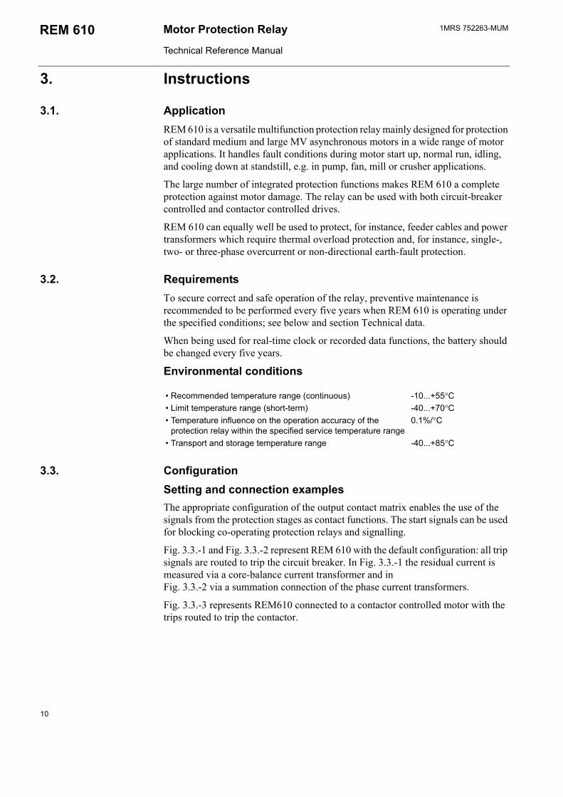
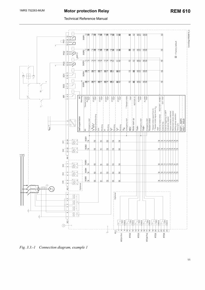
3.3. ConfigurationSetting and connection examplesThe appropriate configuration of the output contact matrix enables the use of the signals from the protection stages as contact functions. The start signals can be used for blocking co-operating protection relays and signalling.
Fig. 3.3.-1 and Fig. 3.3.-2 represent REM 610 with the default configuration: all trip signals are routed to trip the circuit breaker. In Fig. 3.3.-1 the residual current is measured via a core-balance current transformer and in Fig. 3.3.-2 via a summation connection of the phase current transformers.
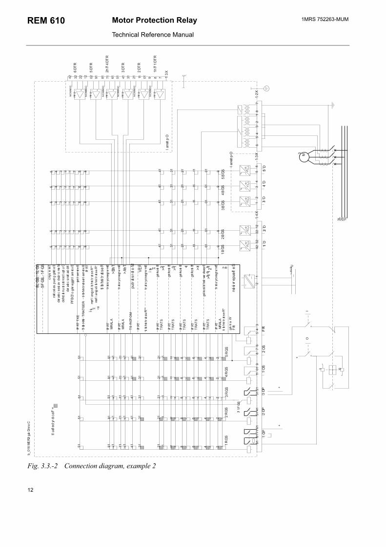
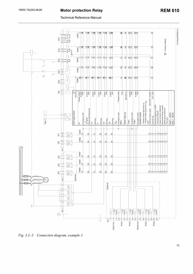
Fig. 3.3.-3 represents REM610 connected to a contactor controlled motor with the trips routed to trip the contactor.
10
1MRS 752263-MUM Motor protection Relay
Technical Reference Manual
REM 610
!
θ" #$ ##"
""
% "
"
&"
"
Σ$#'
((
(
(
(
)*++',-. /0
.1
) 2
) 2
) 2
) 2
) 2
) 2
3$'*+4
56$*-789:4$
;9#$-$'+'0'$
&(&
.<9-,9+67#$-$
&
3998#='$604*6>'+,
&
4*6>'+,
&
4*6>'+,
&
4*6>'+,
&
4*6>'+,
*$*-#$-$3
&(&
.<9-,9+67#$-$
&(&
.<9-,9+67#$-$
;;9#$-$'+'0'$
9#$-$'+'0'$
.&2?
;9#$-$'+'0'$#',+4:-*<θ
>;;9#$-$'+'0'$#',+4:-*<Σ$ #'
.$9-+4-9#$-$'+'0'$
.$9-+4$-',,9-'+,*:)
+8'6$'*+#649-98
$3$6*+$6$#+4$698
9<*-'@98A49#649-98
9$$'+,,-*3#9496$'*+
'<9#7+6
.
.$9-+4$-'3
.<9-,9+67#$-$
3$'*+4
94:#39-A'#'*+
B-+'+,
Fig. 3.3.-1 Connection diagram, example 1
11
1MRS 752263-MUMMotor Protection Relay
Technical Reference Manual
REM 610
!
θ"#$# #
"
""
%"
"
.1
&"
"
Σ$#'
((
(
(
(
)*++',-. /0
) 2
) 2
) 2
) 2
) 2
) 2
3$'*+4
56$*-789:4$
;9#$-$'+
'0'$
&(&
&
3998#='$604*6>'+,
&
4*6>'+,
&
4*6>'+,
&
4*6>'+,
&
4*6>'+,
*$*-#$-$3
&(&
.<9-,9+67#$-$
&(&
.<9-,9+67#$-$
;;9#$-$'+
'0'$
9#$-$'+
'0'$
.&2?
;9#$-$'+
'0'$#',+4:-*
<θ>
;;9#$-$'+
'0'$#',+4:-*
<Σ$#'
.$9-+4-9#$-$'+
'0'$
.$9-+4$-',
,9-'+,*:)
+8'6$'*+#649-98
$3$6*+$6$#+4$698
9<*-'@98A49#649-98
9$$'+,,-*3#9496$'*+
'<9#7+6
.
.$9-+4$-'3
.<9-,9+67#$-$
.<9-,9+67#$-$
3$'*+4
94:#39-A'#'*+
B-+'+,
Fig. 3.3.-2 Connection diagram, example 2
12
1MRS 752263-MUM Motor protection Relay
Technical Reference Manual
REM 610
X3.1
6
5
4
3
2
1X4
.1
RTD
1/Th
1
RTD
2
RTD
3
RTD
4/Th
2
RTD
5
RTD
6
11
11
12
22
22
33
33
34
44
44
55
55
56
66
66
77
77
78
88
88
99
99
910
1010
1010
1111
1111
1112
1212
1212
1313
1313
13
1414
1414
14
1616
1616
1617
1717
1717
1818
1818
1819
1919
1919
1515
1515
15
SG
F1/7
SG
R4
SG
R3
SG
R2
SG
R1
SG
R5
SO
1P
O2
SO
2
3
4 5
6 7
8
9
10
11
12 1
3
1
4 15
1
6 17
18
19
X2.1
7
8 1
2 3
4 5
6
IO
-
PO
3
21
22
23 2
4
1
2
~U a
uxM
3
~
DIF
F
+ -
7 8 9 10
11
12
13
14
15
16
17
18
19
20
21
22
23
24
X3.1
θ> I s2 t
s/Is>
I>>
I< I 0>
I 2>
REV
ThA>
ThB>
Σtsi
SGF1
...SG
F5SG
L1...
SGL8
DIF
F
+ -
DIF
F
+ -
DIF
F
+ -
DIF
F
+ -
DIF
F
+ -
L1
L2
L3
Con
nDia
gr3R
EM
610_
b
PO
1
CO
MM
ON
CO
MM
ON
CO
MM
ON
CO
MM
ON
CO
MM
ON
CO
MM
ON
++
11
11
12
22
22
33
33
34
44
44
66
66
67
77
77
88
88
8
99
99
9
1010
1010
10
1111
11 1
111
1212
1212
12
1313
1313
13
1414
1414
14
SG
B4
SG
B3
SG
B2
SG
B1
SG
B5
55
55
5
~
DI3
DI2
DI1
DI4
DI5
Opt
iona
l
= Fa
ctor
y de
faul
t
*
Res
tart
inhi
bit
ALA
RM
TR
IP
STA
RT
TRIP
Spee
d sw
itch/
bloc
king
STA
RT
TRIP
Blo
ckin
g
STA
RT
TRIP
Blo
ckin
g
STA
RT
TRIP
Blo
ckin
g
STA
RT
TRIP
Blo
ckin
g
TRIP
Mot
or s
tart
upM
OTO
R S
T
ALA
RM
TR
IPE
mer
genc
y st
art
ALA
RM
TR
IPE
mer
genc
y st
art
** R
esta
rt in
hibi
t
Res
tart
inhi
bit
RE
STA
RT
INH
IBIT
* R
esta
rt in
hibi
t sig
nal f
rom
θ>
** R
esta
rt in
hibi
t sig
nal f
rom
Σt s
i TR
IP
Ext
erna
l res
tart
inhi
bit
Exte
rnal
trig
gerin
g of
CBF
P In
dica
tions
cle
ared
O
utpu
t con
tact
s un
latc
hed
Mem
oriz
ed v
alue
s cl
eare
d Se
tting
gro
up s
elec
tion
Tim
e sy
nc
EXT
TR
IPE
xter
nal t
rip
Em
erge
ncy
star
t
Em
erge
ncy
star
t
Opt
iona
l
IRF
Self-
supe
rvis
ion
IRF
War
ning
Fig. 3.3.-3 Connection diagram, example 3
13
1MRS 752263-MUMMotor Protection Relay
Technical Reference Manual
REM 610
4. Technical description
4.1. Functional description
4.1.1. Product functions
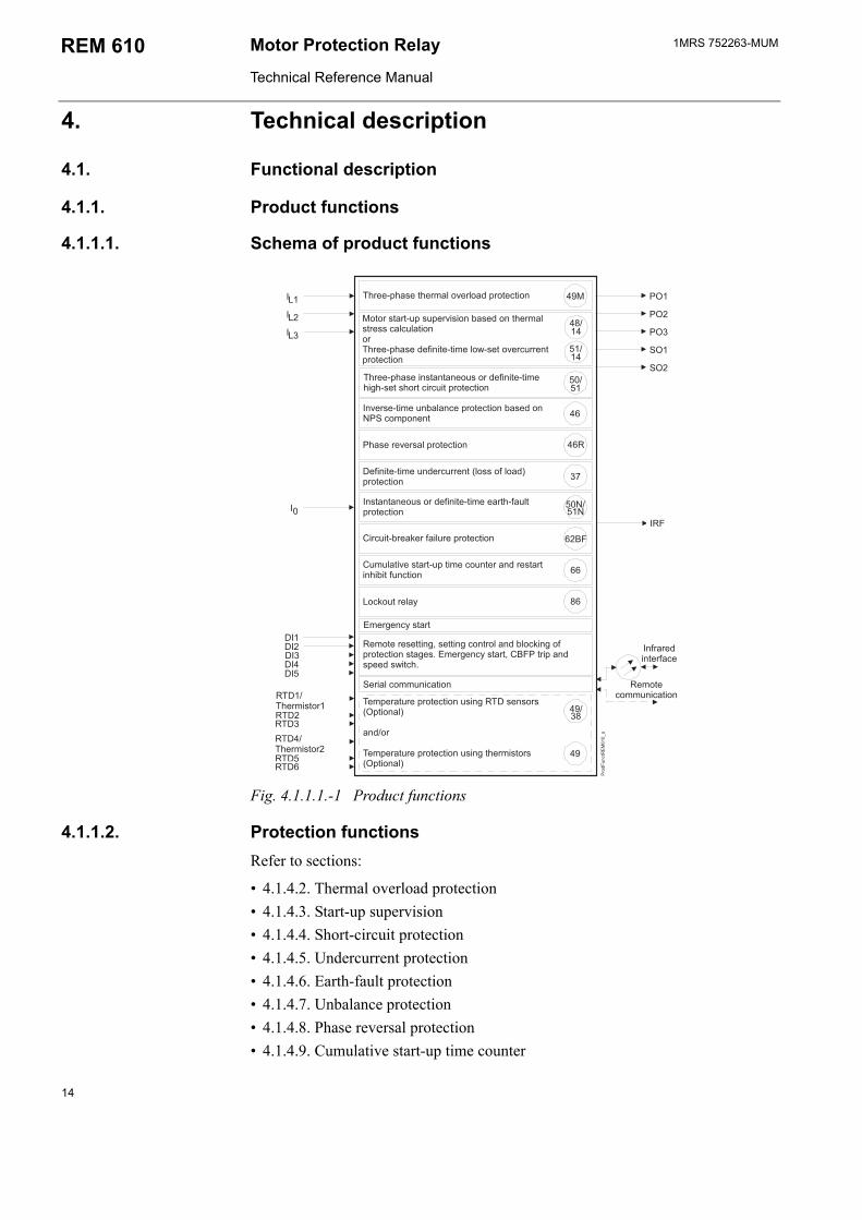
4.1.1.1. Schema of product functions
22
(
(
(
-*8+6$. /
-993#9'+#$+$+9*#*-89:'+'$9$'<9',#9$#*-$6'-6'$3-*$96$'*+
+#$+$+9*#*-89:'+'$9$'<99-$:4$3-*$96$'*+
-993#9$9-<4*A9-4*83-*$96$'*+
.<9-,9+67#$-$
)<4$'A9#$-$3$'<96*+$9-+8-9#$-$'+'0'$:+6$'*+
#9-9A9-#43-*$96$'*+
(*6>*$-947
)'-6'$0-9>9-:'4-93-*$96$'*+
9:'+'$9$'<9+89-6--9+$C4*##*:4*8D3-*$96$'*+
9-<'#$*-
9-<'#$*-
9<39-$-93-*$96$'*+#'+,#9+#*-#C3$'*+4D
+8*-9<39-$-93-*$96$'*+#'+,$9-<'#$*-#C3$'*+4D
+:--98'+$9-:69
9<*$9-9#9$$'+,E#9$$'+,6*+$-*4+804*6>'+,*:3-*$96$'*+#$,9#.<9-,9+67#$-$E) $-'3+8#3998#='$6
9-'46*<<+'6$'*+ 9<*$96*<<+'6$'*+
+A9-#9$'<9+04+693-*$96$'*+0#98*+26*<3*+9+$
*$*-#$-$3#39-A'#'*+0#98*+$9-<4#$-9##6464$'*+*--993#989:'+'$9$'<94*=#9$*A9-6--9+$3-*$96$'*+
Fig. 4.1.1.1.-1 Product functions
4.1.1.2. Protection functionsRefer to sections:
4.1.4.2. Thermal overload protection 4.1.4.3. Start-up supervision 4.1.4.4. Short-circuit protection 4.1.4.5. Undercurrent protection 4.1.4.6. Earth-fault protection 4.1.4.7. Unbalance protection 4.1.4.8. Phase reversal protection 4.1.4.9. Cumulative start-up time counter
14
1MRS 752263-MUM Motor protection Relay
Technical Reference Manual
REM 610
4.1.4.10. Circuit-breaker failure protection 4.1.4.11. Temperature protection (optional)
4.1.1.3. InputsREM 610 includes four energizing inputs, two digital inputs and three optional digital inputs controlled by an external voltage. Three of the energizing inputs are for the phase currents and one for the earth-fault current. For details, refer to section Input/output connections and tables 4.1.4.12-7, 4.2.1-1 and 4.2.1-5. The functions of the digital inputs are determined with the SGB switches.
4.1.1.4. OutputsREM 610 is provided with three power outputs (PO1, PO2 and PO3) and two signal outputs (SO1 and SO2). Switchgroups SGR1...5 are used for routing internal signals from the protection stages, the motor start-up signal and the external trip signal to the desired signal or power output. The minimum pulse length can be configured to be 40 or 80 ms and the power outputs can all be configured to be latched.
4.1.1.5. Emergency startThe emergency start function allows motor start ups although the restart inhibit has been activated. The function is activated in SGB1...5. The emergency start will be activated when the selected digital input is energized and will remain active for ten minutes. On the rising edge of the emergency start signal
the calculated thermal level will be set slightly below the restart inhibit level to allow at least one motor start up
the value of the register of the cumulative start-up time counter will be set slightly below the set restart inhibit value to allow at least one motor start up
the set trip values of temperature stages ThA> and ThB> will be increased by 10 per cent
the external restart inhibit signal will be ignored.
The set trip values of stages ThA> and ThB> will be increased by ten per cent and the external restart inhibit signal ignored for as long as the emergency start is activated. A new emergency start cannot be made until the emergency start signal has been reset and the emergency start time of ten minutes has expired.
Activation of the emergency start signal will generate an event code, which cannot be masked out from the event reporting.
4.1.1.6. Restart inhibitThe restart inhibit signal is used to inhibit motor start ups when the motor is overheated, for instance. The restart inhibit signal is routed to PO3 by default, but can be deselected in SGF1. The signal will be activated when any of the following conditions exists:
the trip signal from any protection stage is active the restart inhibit signal from the thermal protection stage is active the restart inhibit signal from stage Σtsi is active the external restart inhibit signal is active
15
1MRS 752263-MUMMotor Protection Relay
Technical Reference Manual
REM 610
The estimated time to the next possible motor start up, i.e. when the restart inhibit signal is reset, can be accessed either via the HMI or the SPA bus.
Note!
If the restart inhibit function has been activated (SGF1/7=0), SGR3 will be overridden.
4.1.1.7. Motor start upA motor start-up situation is defined by means of the phase currents as follows:
Motor start up begins (the motor start-up signal is activated) when the maximum phase current rises from a value below 0.12 x In, i.e. the motor is at standstill, to a value above 1.5 x In within less than 60 ms.
Motor start up ends (the motor start-up signal is reset) when all phase currents fall below 1.25 x In and remain below for at least 200 ms.
The start-up time of the latest motor start up can be accessed via the HMI and read with SPA parameter V3.
The motor start-up signal is routed to the output contacts with the switches of switchgroups SGR1...SGR5.
Note!
All operation indications on the LCD will be cleared when a motor start up begins.
4.1.1.8. Rated current of the protected unitA scaling factor, PU scale, can be set for the phase currents. This will allow differences between the rated current of the protected unit and that of the energizing input. Consequently, the rated current of the relay can be set to equal the full load current (FLC) of the motor.
The current settings of the protection functions are related to the scaled rated current, In. The measured currents are presented either as primary values or as multiples of the scaled rated current. The current values in the recorded data are presented as multiples of the rated current.
Note!
The scaling factor affects the operation accuracy of the protection functions, with the exception of the earth-fault protection. The stated operation accuracy for each protection function only applies when the scaling factor is 1.
Note!
If the PU scale is set to 0.5, the maximum measured rated current (FLC) is 25 x In.
Note!
The PU scale does not affect the earth fault current, I0.
16
1MRS 752263-MUM Motor protection Relay
Technical Reference Manual
REM 610
4.1.1.9. Disturbance recorderREM 610 includes an internal disturbance recorder which records the momentary measured values, or the RMS curves of the measured signals, and up to eight user-selectable digital signals: the digital input signals and the internal signals from the protection stages. Any digital signal can be set to trigger the recorder on either the falling or rising edge.
4.1.1.10. HMIThe HMI of REM 610 is equipped with six push-buttons, an alphanumeric 2x16 characters LCD, eight programmable indicator LEDs, three indicator LEDs with fixed functionality, and an indicator LED for front communication. The push-buttons are used for navigating in the menu structure and for adjusting setting values.
An HMI password can be set to protect all user-changeable values from being changed by an unauthorised person. The HMI password will remain inactive and will thus not be required for altering parameter values until the default HMI password has been replaced. Entering the HMI password successfully can be selected to generate an event code. This feature can be used to indicate interaction activities via the local HMI. For further information on the HMI, refer to the Operators Manual.
4.1.1.11. Non-volatile memoryREM 610 can be configured to store various data in a non-volatile memory, which will retain its data also in case of loss of auxiliary voltage (provided that the battery has been inserted and is charged). Operation indication messages and LEDs, the number of motor start ups, disturbance recorder data, event codes and recorded data can all be configured to be stored in the non-volatile memory whereas setting values will always be stored in the EEPROM.
4.1.1.12. Self-supervisionThe self-supervision system of REM 610 manages run-time fault situations and informs the user about an existing fault.
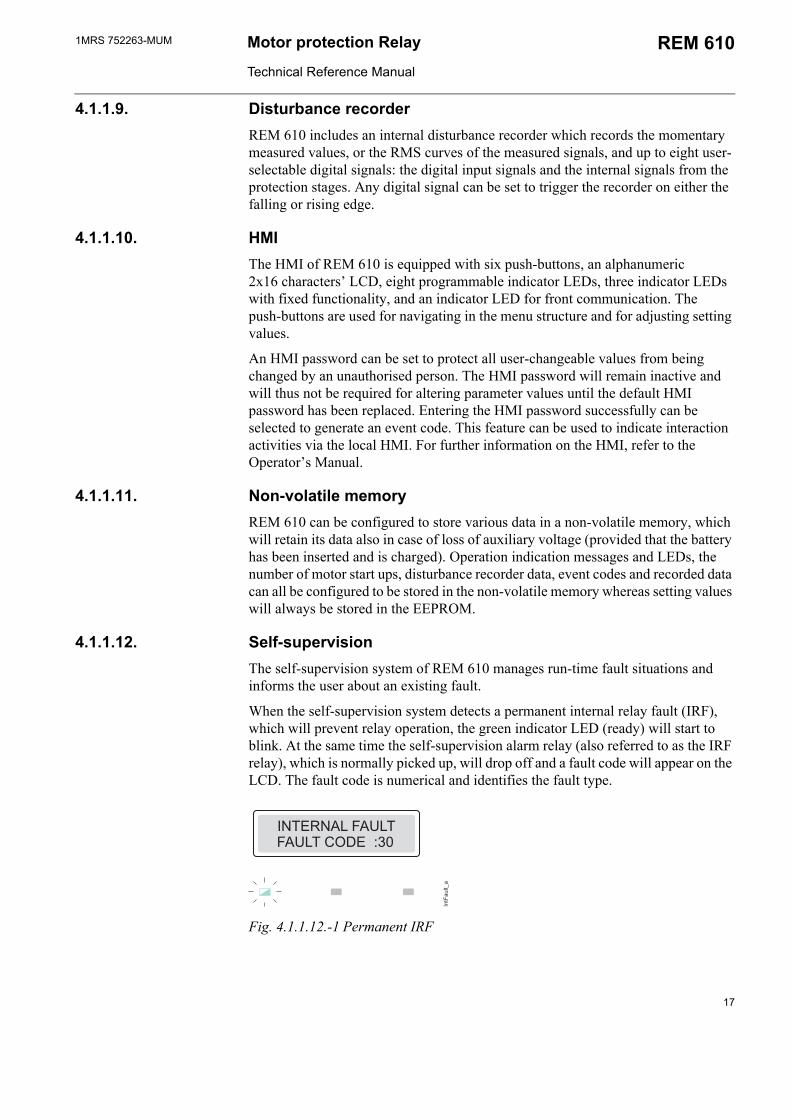
When the self-supervision system detects a permanent internal relay fault (IRF), which will prevent relay operation, the green indicator LED (ready) will start to blink. At the same time the self-supervision alarm relay (also referred to as the IRF relay), which is normally picked up, will drop off and a fault code will appear on the LCD. The fault code is numerical and identifies the fault type.
Fig. 4.1.1.12.-1 Permanent IRF
17
1MRS 752263-MUMMotor Protection Relay
Technical Reference Manual
REM 610
IRF codes can indicate:
no response on the output contact test faulty program, work or parameter memory internal reference voltage error
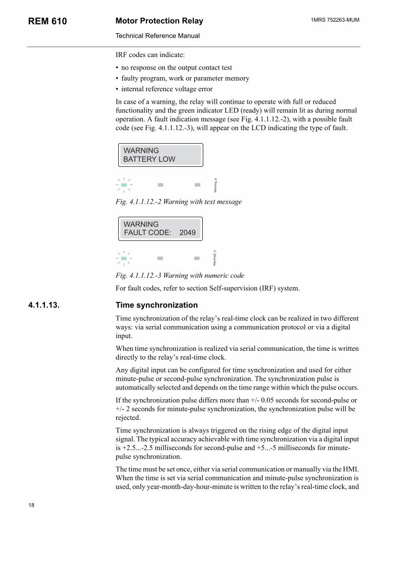
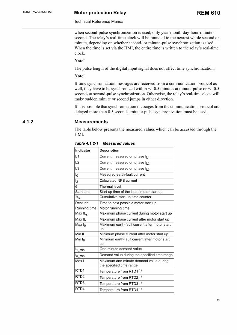
In case of a warning, the relay will continue to operate with full or reduced functionality and the green indicator LED (ready) will remain lit as during normal operation. A fault indication message (see Fig. 4.1.1.12.-2), with a possible fault code (see Fig. 4.1.1.12.-3), will appear on the LCD indicating the type of fault.
Fig. 4.1.1.12.-2 Warning with text message
!
Fig. 4.1.1.12.-3 Warning with numeric code
For fault codes, refer to section Self-supervision (IRF) system.
4.1.1.13. Time synchronizationTime synchronization of the relays real-time clock can be realized in two different ways: via serial communication using a communication protocol or via a digital input.
When time synchronization is realized via serial communication, the time is written directly to the relays real-time clock.
Any digital input can be configured for time synchronization and used for either minute-pulse or second-pulse synchronization. The synchronization pulse is automatically selected and depends on the time range within which the pulse occurs.
If the synchronization pulse differs more than +/- 0.05 seconds for second-pulse or +/- 2 seconds for minute-pulse synchronization, the synchronization pulse will be rejected.
Time synchronization is always triggered on the rising edge of the digital input signal. The typical accuracy achievable with time synchronization via a digital input is +2.5...-2.5 milliseconds for second-pulse and +5...-5 milliseconds for minute-pulse synchronization.
The time must be set once, either via serial communication or manually via the HMI. When the time is set via serial communication and minute-pulse synchronization is used, only year-month-day-hour-minute is written to the relays real-time clock, and
18
1MRS 752263-MUM Motor protection Relay
Technical Reference Manual
REM 610
when second-pulse synchronization is used, only year-month-day-hour-minute-second. The relays real-time clock will be rounded to the nearest whole second or minute, depending on whether second- or minute-pulse synchronization is used. When the time is set via the HMI, the entire time is written to the relays real-time clock.
Note!
The pulse length of the digital input signal does not affect time synchronization.
Note!
If time synchronization messages are received from a communication protocol as well, they have to be synchronized within +/- 0.5 minutes at minute-pulse or +/- 0.5 seconds at second-pulse synchronization. Otherwise, the relays real-time clock will make sudden minute or second jumps in either direction.
If it is possible that synchronization messages from the communication protocol are delayed more than 0.5 seconds, minute-pulse synchronization must be used.
4.1.2. MeasurementsThe table below presents the measured values which can be accessed through the HMI.
Table 4.1.2-1 Measured values
Indicator DescriptionL1 Current measured on phase IL1
L2 Current measured on phase IL2
L3 Current measured on phase IL3
I0 Measured earth-fault current
I2 Calculated NPS current
θ Thermal levelStart time Start-up time of the latest motor start upΣts Cumulative start-up time counter
Rest.inh. Time to next possible motor start upRunning time Motor running timeMax ILs Maximum phase current during motor start up
Max IL Maximum phase current after motor start upMax I0 Maximum earth-fault current after motor start
upMin IL Minimum phase current after motor start upMin I0 Minimum earth-fault current after motor start
upI1_min One-minute demand value
In_min Demand value during the specified time range
Max I Maximum one-minute demand value during the specified time range
RTD1 Temperature from RTD1 1)
RTD2 Temperature from RTD2 1)
RTD3 Temperature from RTD3 1)
RTD4 Temperature from RTD4 1)
19
1MRS 752263-MUMMotor Protection Relay
Technical Reference Manual
REM 610
1) Optional
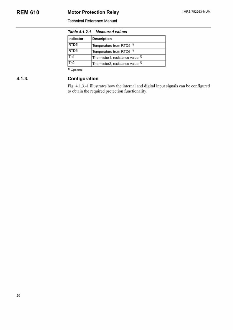
4.1.3. ConfigurationFig. 4.1.3.-1 illustrates how the internal and digital input signals can be configured to obtain the required protection functionality.
RTD5 Temperature from RTD5 1)
RTD6 Temperature from RTD6 1)
Th1 Thermistor1, resistance value 1)
Th2 Thermistor2, resistance value 1)
Table 4.1.2-1 Measured values
Indicator Description
20

1MRS 752263-MUM Motor protection Relay
Technical Reference Manual
REM 610
X3.1
6
5
4
3
2
1X4
.1
11
11
12
22
22
33
33
34
44
44
55
55
56
66
66
77
77
78
88
88
99
99
910
1010
1010
1111
1111
1112
1212
1212
1313
1313
13
1414
1414
14
1616
1616
1617
1717
1717
1818
1818
1819
1919
1919
1515
1515
15
SG
F1/7
SG
R4
SG
R3
SG
R2
SG
R1
SG
R5
SO
1P
O2
PO
1S
O2
IRF
3
4 5
6 7
8
9
10
11
12 1
3
1
4 15
1
6 17
18
19
PO
3
21 2
2
23
24
θ> I s2 t
s/Is>
I>>
I< I 0>
I 2>
REV
ThA>
ThB>
Σtsi
SGF1
...SG
F5SG
L1...
SGL8
IL1
IL2
IL3 Io
RTD
1/Th
1 R
TD2
RTD
3R
TD4/
Th2
RTD
5 R
TD6
Sig
nDia
grR
EM
610_
b
11
11
12
22
22
33
33
34
44
44
66
66
67
77
77
88
88
8
99
99
9
1010
1010
10
1111
11 1
111
1212
1212
12
1313
1313
13
1414
1414
14
SG
B4
SG
B3
SG
B2
SG
B1
SG
B5
55
55
5
DI3
DI2
DI1
DI4
DI5
Opt
iona
l
* R
esta
rt in
hibi
t AL
AR
M
TRIP
Em
erge
ncy
star
t
STA
RT
TRIP
Spee
d sw
itch/
bloc
king
STA
RT
TRIP
Blo
ckin
g
STA
RT
TRIP
Blo
ckin
g
STA
RT
TRIP
Blo
ckin
g
STA
RT
TRIP
Blo
ckin
g
TRIP
Mot
or s
tart
upM
OTO
R S
T
ALA
RM
TR
IPE
mer
genc
y st
art
ALA
RM
TR
IPE
mer
genc
y st
art
** R
esta
rt in
hibi
t
Res
tart
inhi
bit
RE
STA
RT
INH
IBIT
* R
esta
rt in
hibi
t sig
nal f
rom
θ>
** R
esta
rt in
hibi
t sig
nal f
rom
Σt s
i TR
IP
Ext
erna
l res
tart
inhi
bit
Exte
rnal
trig
gerin
g of
CBF
P In
dica
tions
cle
ared
O
utpu
t con
tact
s un
latc
hed
Mem
oriz
ed v
alue
s cl
eare
d Se
tting
gro
up s
elec
tion
Tim
e sy
nc
EXT
TR
IPE
xter
nal t
rip
Em
erge
ncy
star
t
Self-
supe
rvis
ion
IRF
War
ning
Fig. 4.1.3.-1 Signal diagram
21
1MRS 752263-MUMMotor Protection Relay
Technical Reference Manual
REM 610
The functions of the relay are selected with the switches of switchgroups SGF, SGB, SGR and SGL. The checksums of the switchgroups are found under SETTINGS in the HMI menu. The functions of the switches are explained in detail in the corresponding SG_ tables.
4.1.4. Protection
4.1.4.1. Block diagram
LED1 LED2 LED3 LED4 LED5 LED6 LED7 LED8
IL1 IL2 IL3
PO1 PO2 PO3 SO1 SO2
IRF
RTD1/Th1 RTD2 RTD3 RTD4/Th2 RTD5 RTD6
SGB1...5
SGR1...5
I0
PO2
Th1 Th2
IL1 IL2 IL3
Io
CTR1 CTR2 CTR3 CTR4 CTR5 CTR6
CTR, T
I2t>, Is2ts
Is>, Is & ts
θ>
Σts>
I>> I0>
II<
I2> I0
REV
200 ms
CBFP
Th1> Ta1...3>, Tp1...3>
Th2> Ta4...6>, Tp4...6>
2 s
2 s
SGL1...8
SGF1...SGF5
BlockDiagrREM610_b
IL 1 IL 2 IL 3 I0
PO1
Programmable LEDs
ER ST AMB TEMP
RESTART INH ALARM
TRIP
Disturbance recorder (4 analogue + up to 8 digital channels)
Digital outputs (Output contacts)
IRF INDICATION START/ALARM INDICATION TRIP INDICATION
IRF indication LED (green) Start/Alarm (yellow) and trip (red) indication LEDs
θ> ALARM θ> TRIP
The dashed line indicates optional functionality. 1) Stall indication from speed switch 2) Emergency start 3) Clear indications by the digital input signal 4) Clear indications and unlatch output contacts by the digital input signal 5) Reset indications and memorized values; unlatch output contacts by the digital input signal
Optional digital inputs (RTD module)
Digital inputs DI1 DI2 DI3 DI4 DI5
Switchgroups for digital inputs Protection relay functions
Analogue inputs
Optional RTD inputs (RTD module)
Switchgroups for programmable LEDs
Switchgroups for output contacts
RESTART INH
MOTOR ST ER ST
I>> START I0> START I2> START I< START
θ> ALARM θ> TRIP
DOUBLE BLOCK
START TRIP
BLOCKSTART
TRIP
NPS BLOCK
START TRIP
NPS MOTOR ST
TRIP
EXT TRIG
STALL MOTOR ST
START TRIP
STALLSTART
TRIP
BLOCK
START TRIP
NPS
Motor start up
DOUBLE MOTOR ST
AMB TEMP
RTD, T
ER ST
ThA>ALARM ThA>TRIP
ThB> TRIP ER ST
ThB> ALARM ThB> TRIP
ThA> TRIP
REV
CBFP
Thermistor, Th
RESTART INH
Is2ts/Is> START
Is2ts/Is> TRIP
I>> START I>> TRIP I< START I< TRIP I0> START I0> TRIP I2> START I2> TRIP REV TRIP MOTOR ST EXT TRIP ThA> ALARM ThA> TRIP ThB> ALARM ThB> TRIP
Is2ts/Is> TRIP
I>> TRIP I0> TRIP I2> TRIP
REV TRIP I< TRIP
Is2ts/Is> START
θ> ALARM θ> TRIP RESTART INH MOTOR ST Is
2ts/Is> TRIP I>> TRIP I< TRIP I0> TRIP I2> TRIP REV TRIP ER ST DI1 DI2 DI3 DI4 DI5 ThA> ALARM ThA> TRIP ThB> ALARM ThB> TRIP
Reset 1 3) Reset 2 4)Reset 3 5) Setting group Time sync EXT TRIP EXT TRIG CBFP RESTART INH ER ST 2) STALL 1)BLOCK I>> BLOCK I0> BLOCK I< BLOCK I2>
DI1 DI2 DI3 DI4 DI5 MOTOR ST
Warning
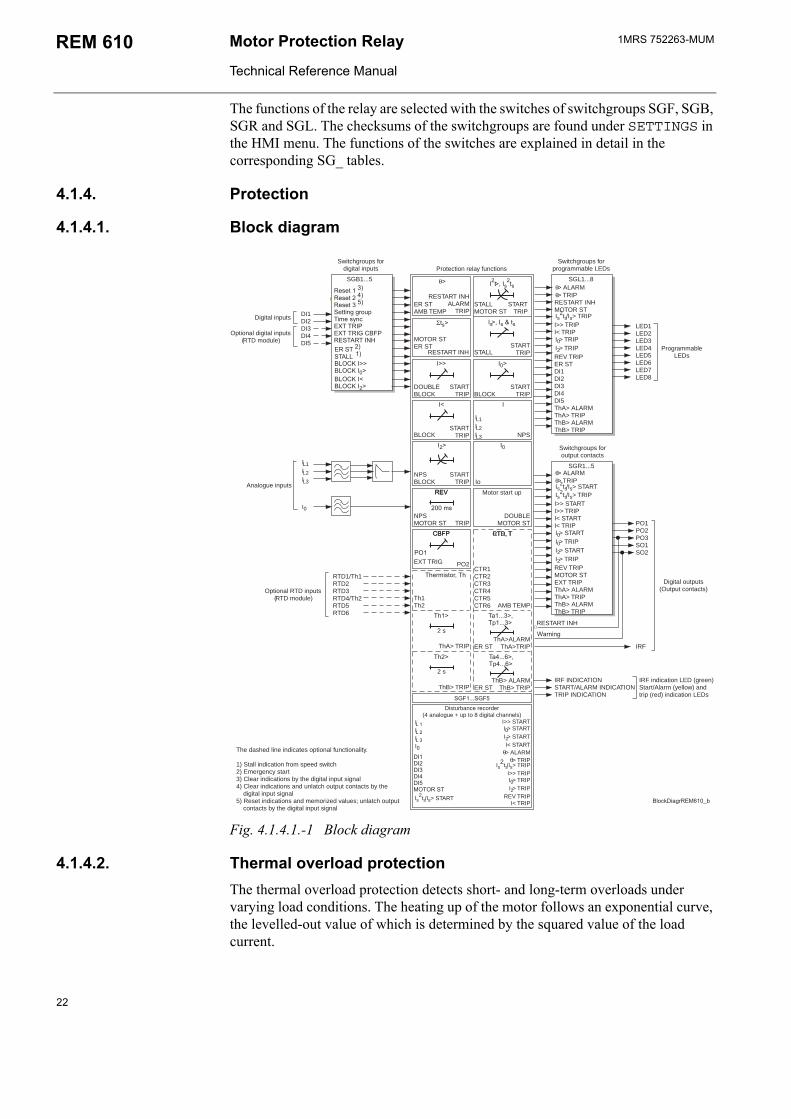
Fig. 4.1.4.1.-1 Block diagram
4.1.4.2. Thermal overload protectionThe thermal overload protection detects short- and long-term overloads under varying load conditions. The heating up of the motor follows an exponential curve, the levelled-out value of which is determined by the squared value of the load current.
22
1MRS 752263-MUM Motor protection Relay
Technical Reference Manual
REM 610
The full load current of the motor is defined by means of the protected unit scaling factor and determines the thermal trip level of stage θ>, θt. The set safe stall time, t6x, determines the operate time of the stage for a load current of 6 x FLC without prior load.
If the RTD module has been installed, RTD6 can be selected to measure the ambient temperature. The selection is made in SGF4. However, if RTD6 is not used for measuring the ambient temperature or if the RTD module has not been installed, the thermal protection will use the set ambient temperature, Tamb.
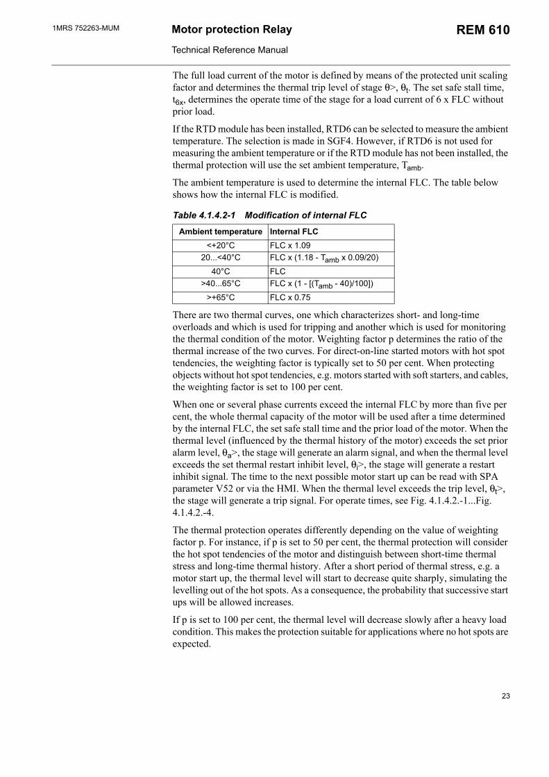
The ambient temperature is used to determine the internal FLC. The table below shows how the internal FLC is modified.
Table 4.1.4.2-1 Modification of internal FLC
Ambient temperature Internal FLC<+20°C FLC x 1.09
20...<40°C FLC x (1.18 - Tamb x 0.09/20)
40°C FLC>40...65°C FLC x (1 - [(Tamb - 40)/100])
>+65°C FLC x 0.75
There are two thermal curves, one which characterizes short- and long-time overloads and which is used for tripping and another which is used for monitoring the thermal condition of the motor. Weighting factor p determines the ratio of the thermal increase of the two curves. For direct-on-line started motors with hot spot tendencies, the weighting factor is typically set to 50 per cent. When protecting objects without hot spot tendencies, e.g. motors started with soft starters, and cables, the weighting factor is set to 100 per cent.
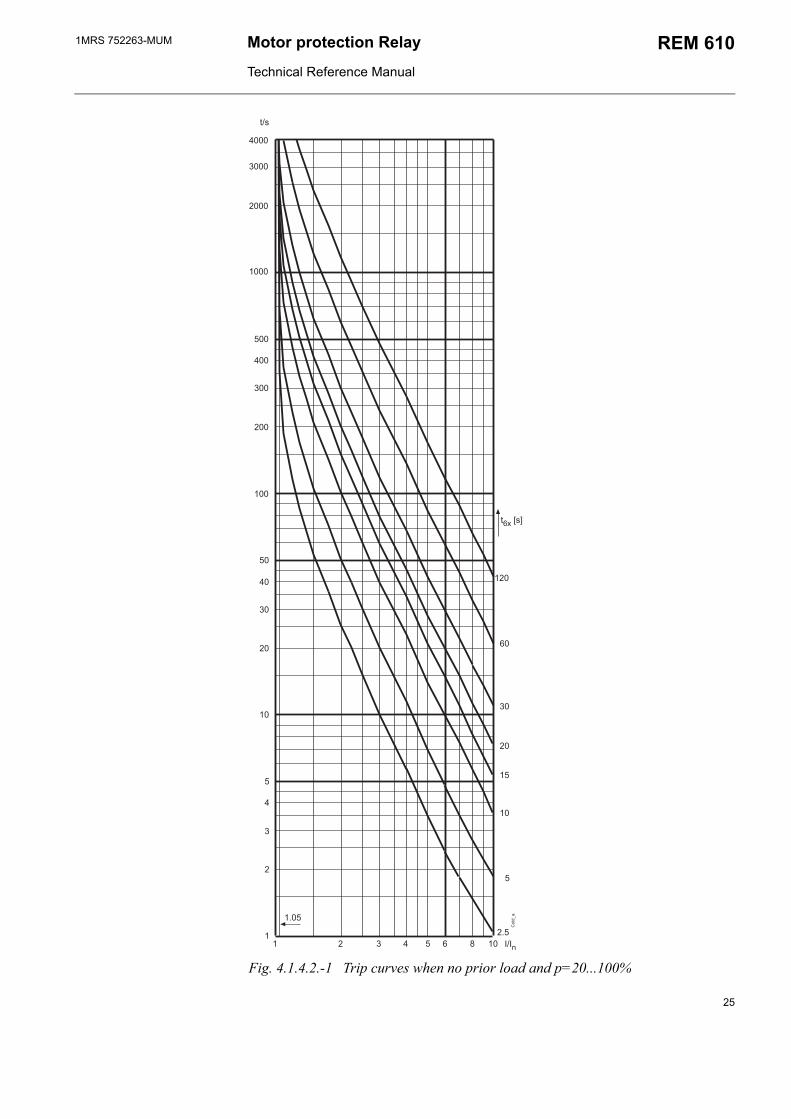
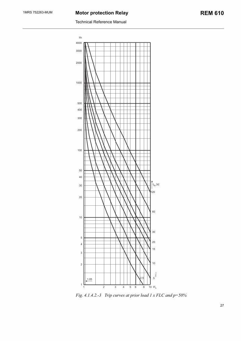
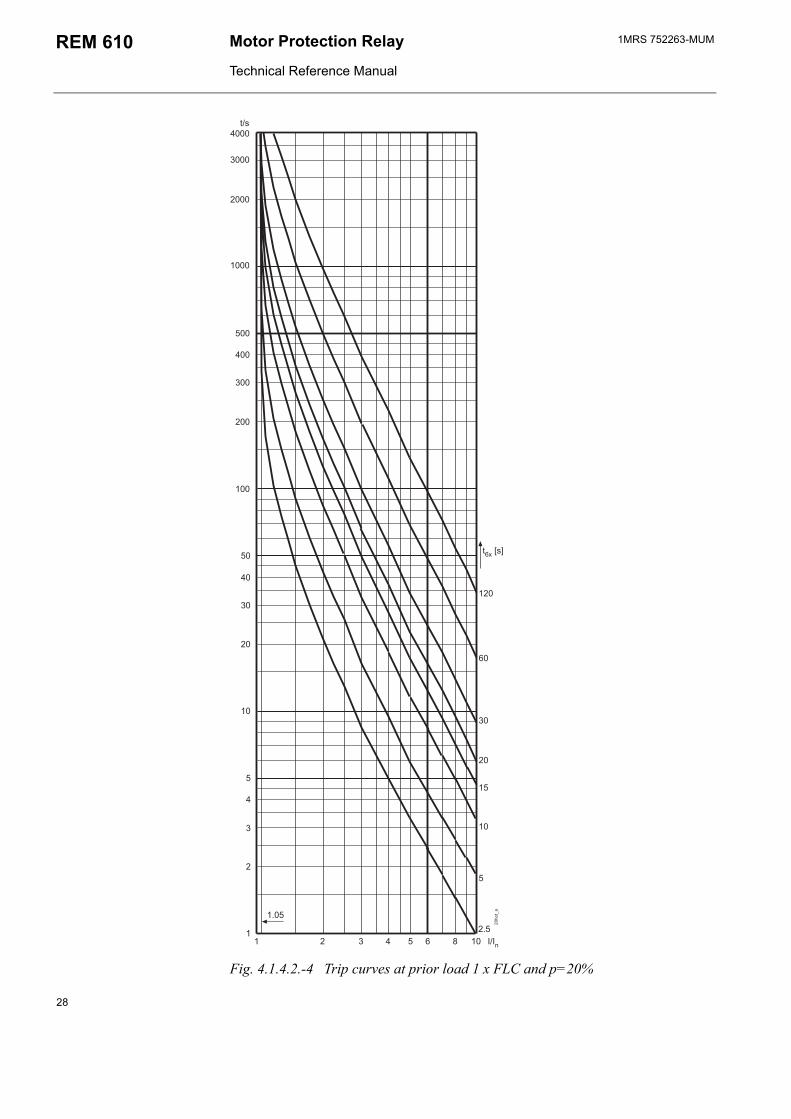
When one or several phase currents exceed the internal FLC by more than five per cent, the whole thermal capacity of the motor will be used after a time determined by the internal FLC, the set safe stall time and the prior load of the motor. When the thermal level (influenced by the thermal history of the motor) exceeds the set prior alarm level, θa>, the stage will generate an alarm signal, and when the thermal level exceeds the set thermal restart inhibit level, θi>, the stage will generate a restart inhibit signal. The time to the next possible motor start up can be read with SPA parameter V52 or via the HMI. When the thermal level exceeds the trip level, θt>, the stage will generate a trip signal. For operate times, see Fig. 4.1.4.2.-1...Fig. 4.1.4.2.-4.
The thermal protection operates differently depending on the value of weighting factor p. For instance, if p is set to 50 per cent, the thermal protection will consider the hot spot tendencies of the motor and distinguish between short-time thermal stress and long-time thermal history. After a short period of thermal stress, e.g. a motor start up, the thermal level will start to decrease quite sharply, simulating the levelling out of the hot spots. As a consequence, the probability that successive start ups will be allowed increases.
If p is set to 100 per cent, the thermal level will decrease slowly after a heavy load condition. This makes the protection suitable for applications where no hot spots are expected.
23
1MRS 752263-MUMMotor Protection Relay
Technical Reference Manual
REM 610
The reduced ability of the motor to cool down during standstill is taken into account by setting the cooling time constant to be longer than the heating time constant. The time constant multiplier, Kc, is the ratio of the cooling time and the heating time constant and determines the cooling rate of the motor at standstill.
At power up, the thermal level will be set to approximately 70 per cent of the thermal capacity of the motor. This will ensure that the stage will trip within a safe time span. Under a low-load condition, the calculated thermal level will slowly approach the thermal level of the motor.
Note!
At a low prior alarm level, connecting the auxiliary supply to the relay will cause a thermal alarm due to the initialization of the thermal level to 70 per cent. The thermal level can be reset via the HMI during power up.
Note!
The thermal level can be reset or changed via serial communication, which will generate an event code.
Note!
On the rising edge of the emergency start signal the thermal level will be set below the thermal restart inhibit level. This will allow at least one motor start up even though the thermal level has exceeded the restart inhibit level.
Note!
When stage θ> starts during motor start up, neither a start signal nor an event code will be generated.
24
1MRS 752263-MUM Motor protection Relay
Technical Reference Manual
REM 610
Fig. 4.1.4.2.-1 Trip curves when no prior load and p=20...100%
25
1MRS 752263-MUMMotor Protection Relay
Technical Reference Manual
REM 610
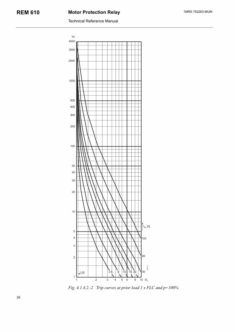
Fig. 4.1.4.2.-2 Trip curves at prior load 1 x FLC and p=100%
26
1MRS 752263-MUM Motor protection Relay
Technical Reference Manual
REM 610
Fig. 4.1.4.2.-3 Trip curves at prior load 1 x FLC and p=50%
27
1MRS 752263-MUMMotor Protection Relay
Technical Reference Manual
REM 610
Fig. 4.1.4.2.-4 Trip curves at prior load 1 x FLC and p=20%
28
1MRS 752263-MUM Motor protection Relay
Technical Reference Manual
REM 610
4.1.4.3. Start-up supervisionStart-up supervision can be based on either definite-time overcurrent protection or thermal stress calculation. The selection is made in SGF3, the default being thermal stress calculation.
Start-up supervision based on definite-time overcurrent protectionThe non-directional low-set stage, Is>, detects overcurrent, caused by an overload or a short circuit, for instance. When one or several phase currents exceed the set start value of stage Is>, the stage will generate a start signal after a ~ 55 ms start time. When the set operate time elapses, the stage will generate a trip signal.
The overcurrent stage will be reset when all three phase currents have fallen below the set start value of the stage. The resetting time depends on how sharp the drop is: if the phase currents fall below 0.5 x Is>, the stage will be reset in 10 ms; if the phase currents fall below Is> but not below 0.5 x Is>, the stage will be reset in 50 ms. It is possible to block the tripping of the low-set overcurrent stage by applying a digital input signal to the relay.
A disadvantage of start-up supervision based on definite-time overcurrent protection is that the operate time is fixed and cannot be extended during low-voltage conditions.
Note!
Stage Is> cannot be used concurrently with stage Is2 x ts.
Note!
When stage Is> starts during motor start up, no start signal will be generated.
Start-up supervision based on thermal stress calculationStage Is
2 x ts detects thermal stress, caused by a locked rotor during motor start up, for instance. The stage can be set to start either when the conditions for motor start up are met or when one or several phase currents exceed the set start value. The selection is made in SGF3.
When stage Is2 x ts has been set to start when the conditions for motor start up are
met, the stage will calculate the thermal stress value, I2 x t, for as long as the conditions for motor start up are met and compare it to a reference value, Is
2 x ts. The reference value is set to equal the amount of thermal stress built up during a normal start up of the motor. The stage will not generate a separate start signal. When the reference value is exceeded, the stage will generate a trip signal. The stage will be reset in 240 ms after the motor start up has ended and the motor is running.
When stage Is2 x ts has been set to start when one or several phase currents exceed
the set start value (IL>Is), the stage will generate a start signal after a ~ 100 ms start time and calculate the thermal stress value, I2 x t, until all three phase currents have fallen below the set start value. When the calculated value exceeds the reference value, Is
2 x ts, the stage will generate a trip signal. The stage will be reset in 240 ms after all three phase currents have fallen below the set start value of the stage.
29
1MRS 752263-MUMMotor Protection Relay
Technical Reference Manual
REM 610
The operate time is calculated as below. However, the shortest possible operate time of stage Is
2 x ts is ~300 ms.
t s[ ]I( s )2> ts× >
I2-------------------------------------------=
where
t = operate timeIs> = set start-up current for motor
ts> = set start-up time for motor
I = phase current value
An advantage of start-up supervision based on thermal stress calculation is that the operate time will be automatically extended during low-voltage conditions as it depends on the start-up current of the motor.
Note!
Stage Is2 x ts cannot be used concurrently with stage Is>.
Start-up supervision with speed switchIn case the safe stall time is shorter than the start-up time of the motor stated by the motor manufacturer, as with motors of ExE-type, for instance, a speed switch on the motor shaft is required to give information on whether the motor is accelerating during motor start up. The speed switch should be open at standstill and closed during acceleration.
Stages Is> and Is2 x ts will be blocked on activation of the speed switch input.
4.1.4.4. Short-circuit protectionThe non-directional short-circuit protection detects overcurrent caused by interwinding, phase-to-phase and phase-to-earth short circuits.
When one or several phase currents exceed the set start value of stage I>>, the stage will generate a start signal after a ~ 50 ms start time. When the set operate time at definite-time characteristic elapses, the stage will generate a trip signal. The high-set overcurrent stage can be given an instantaneous characteristic by setting the operate time to the minimum, i.e. 0.05 s. The stage will be reset in 50 ms after all three phase currents have fallen below the set start value of the stage.
The set start value of stage I>> can be set to be automatically doubled in a motor start-up situation, i.e. when the object to be protected is being connected to a network. Consequently, a set start value below the connection inrush current level can be selected for the stage. In this case, the short-circuit protection will still detect overcurrent caused by a locked rotor when the motor is running, which in turn may be caused by bearing failure, for instance. The selection is made in SGF3.
Note!
When automatic doubling is in use and the PU scale has been set to be very low, it must be assured that the doubled set start value of stage I>> does not exceed the maximum measured current.
30
1MRS 752263-MUM Motor protection Relay
Technical Reference Manual
REM 610
Note!
If the PU scale has been set to 0.5, the maximum measured rated current (FLC) is 25 x In.
It is possible to block the tripping of the high-set overcurrent stage by applying a digital input signal to the relay.
The high-set overcurrent stage can be set out of operation in SGF3 to prevent the contactor in a contactor controlled drive from operating at too high phase currents. This state will be indicated by dashes on the LCD and by 999 when the set start value is read via serial communication.
Note!When stage I>> starts during motor start up, no start signal will be generated.
4.1.4.5. Undercurrent protectionThe non-directional undercurrent protection detects loss of load, caused by a damaged pump or a broken conveyor, for instance, and can be used in applications where undercurrent is considered a fault condition.
When all three phase currents fall below the set start value of stage I<, the stage will generate a start signal after a ~ 300 ms start time. When the set operate time elapses, the stage will generate a trip signal. To avoid tripping a de-energized motor, stage I< will be set out of operation when all phase currents fall below twelve per cent of the FLC of the motor.
The undercurrent stage will be reset in 350 ms after one or several phase currents have exceeded the set start value of the stage.
It is possible to block the tripping of the undercurrent stage by applying a digital input signal to the relay.
Stage I< can be set out of operation in SGF3. This state will be indicated by dashes on the LCD and by 999 when the set start value is read via serial communication.
Note!
When stage I< starts during motor start up, no start signal will be generated.
4.1.4.6. Earth-fault protectionThe non-directional earth-fault current protection detects phase-to-earth currents, caused by ageing and thermal cycling, for instance.
When the earth-fault current exceeds the set start value of stage I0>, the stage will generate a start signal after a ~ 50 ms start time. When the set operate time at definite-time characteristic elapses, the stage will generate a trip signal. The stage can be given an instantaneous characteristic by setting the operate time to the minimum, i.e. 0.05 s. The earth-fault stage will be reset in 50 ms after the earth-fault current has fallen below the set start value of the stage.
It is possible to block the tripping of the earth-fault stage by applying a digital input signal to the relay.
Stage I0> can be set out of operation in SGF3. This state will be indicated by dashes on the LCD and by 999 when the set start value is read via serial communication.
31
1MRS 752263-MUMMotor Protection Relay
Technical Reference Manual
REM 610
To prevent the contactor in a contactor controlled drive from operating at too high phase currents, the earth-fault stage can be set to be inhibited when one or several phase currents exceed the FLC of the motor four, six or eightfold. The selection is made in SGF4.
Note!
When stage I0> starts during motor start up, no start signal will be generated.
Note!
The PU scale does not affect the earth fault current, I0.
4.1.4.7. Unbalance protectionThe inverse-definite-minimum-time (IDMT) unbalance protection is based on the calculated negative-phase-sequence (NPS) current and detects phase unbalance between phases IL1, IL2 and IL3, caused by a broken conductor, for instance. Phase unbalance in a network feeding the motor will cause overheating of the rotor.
When the calculated NPS current value exceeds the set start value of stage I2>, the stage will generate a start signal after a ~ 100 ms start time. When the calculated operate time elapses, the stage will generate a trip signal. The operate time depends on the current value: the higher the current value, the shorter the operate time. The unbalance stage will be reset in 200 ms after the NPS current has fallen below the set start value of the stage.
The unbalance protection will be inhibited when all phase currents fall below twelve per cent of the FLC of the motor or one or several phase currents exceed the FLC of the motor fourfold.
It is possible to block the tripping of the unbalance stage by applying a digital input signal to the relay.
Stage I2> can be set out of operation in SGF3. This state will be indicated by dashes on the LCD and by 999 when the set start value is read via serial communication.
The operate time is calculated as below:
t s[ ]K2
I2( )2 I( 2 )2>------------------------------------------=
where
t = operate time
I2 = NPS current
I2> = set start value
K2 = set time constant equals the motor constant, I22 x t (provided by the motor
manufacturer)
Note!
When stage I2> starts during motor start up, no start signal will be generated.
Note!
Stage I2> will be blocked during the tripping of the phase reversal stage.
32
1MRS 752263-MUM Motor protection Relay
Technical Reference Manual
REM 610
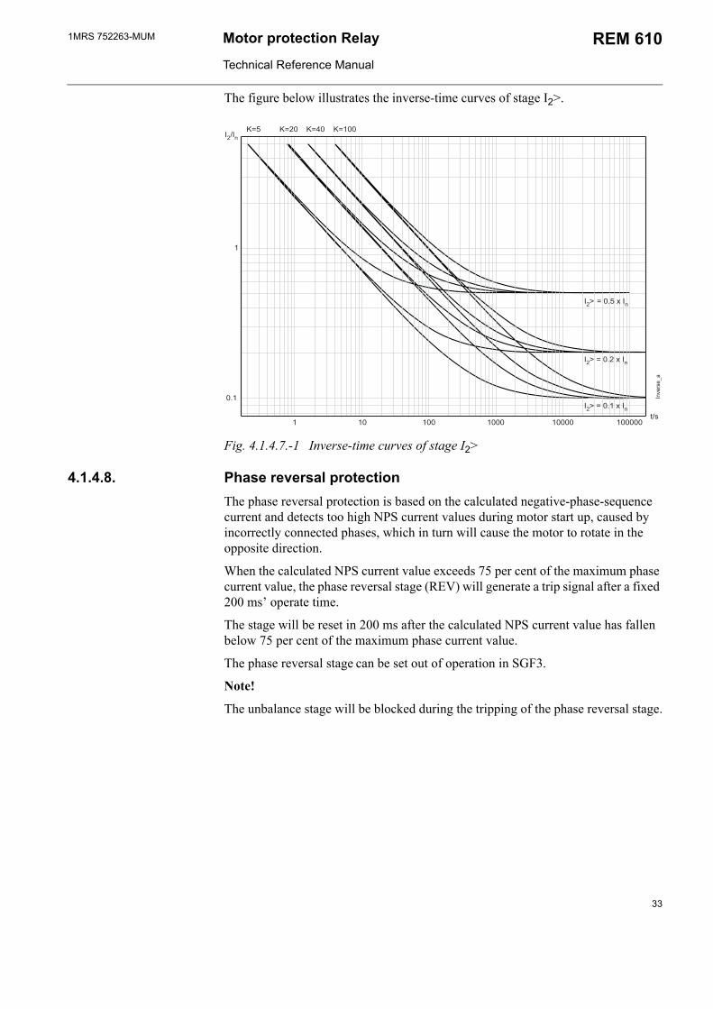
The figure below illustrates the inverse-time curves of stage I2>.
Fig. 4.1.4.7.-1 Inverse-time curves of stage I2>
4.1.4.8. Phase reversal protectionThe phase reversal protection is based on the calculated negative-phase-sequence current and detects too high NPS current values during motor start up, caused by incorrectly connected phases, which in turn will cause the motor to rotate in the opposite direction.
When the calculated NPS current value exceeds 75 per cent of the maximum phase current value, the phase reversal stage (REV) will generate a trip signal after a fixed 200 ms operate time.
The stage will be reset in 200 ms after the calculated NPS current value has fallen below 75 per cent of the maximum phase current value.
The phase reversal stage can be set out of operation in SGF3.
Note!
The unbalance stage will be blocked during the tripping of the phase reversal stage.
33
1MRS 752263-MUMMotor Protection Relay
Technical Reference Manual
REM 610
4.1.4.9. Cumulative start-up time counterThe cumulative start-up time counter detects too frequent start-up attempts, which cause overheating of the motor.
The start-up time of every motor start up is added to a register, Σts. When the registers value exceeds the set restart inhibit value, Σtsi, any attempt to restart the motor will be inhibited.
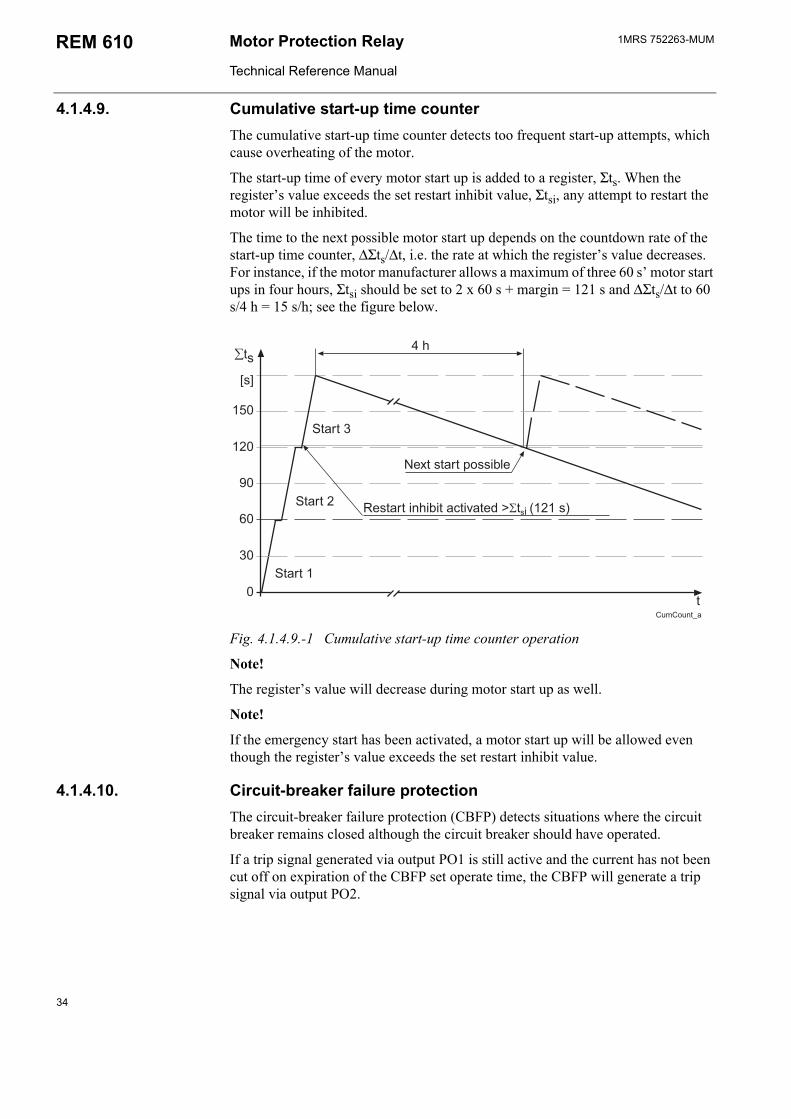
The time to the next possible motor start up depends on the countdown rate of the start-up time counter, ∆Σts/∆t, i.e. the rate at which the registers value decreases. For instance, if the motor manufacturer allows a maximum of three 60 s motor start ups in four hours, Σtsi should be set to 2 x 60 s + margin = 121 s and ∆Σts/∆t to 60 s/4 h = 15 s/h; see the figure below.
!"!
#
#
#
$%&'
(&&'&)&&* +
Fig. 4.1.4.9.-1 Cumulative start-up time counter operation
Note!
The registers value will decrease during motor start up as well.
Note!
If the emergency start has been activated, a motor start up will be allowed even though the registers value exceeds the set restart inhibit value.
4.1.4.10. Circuit-breaker failure protectionThe circuit-breaker failure protection (CBFP) detects situations where the circuit breaker remains closed although the circuit breaker should have operated.
If a trip signal generated via output PO1 is still active and the current has not been cut off on expiration of the CBFP set operate time, the CBFP will generate a trip signal via output PO2.
34
1MRS 752263-MUM Motor protection Relay
Technical Reference Manual
REM 610
The CBFP will not be triggered in case of:
an alarm or a trip of the thermal protection stage an alarm or a trip a temperature stage a trip of the phase reveral stage an external trip
The CBFP can also be selected to be triggered by applying a digital input signal to the relay. In this case, the CBFP will generate a trip signal via output PO2 if the current has not been cut off on expiration of the set operate time. External triggering will be inhibited when all phase currents fall below 12 per cent of the FLC of the motor, i.e. at standstill.
Internal triggering is selected by activating the CBFP in SGF and external triggering by activating the CBFP in SGB. Both triggering options can be selected at the same time.
Normally, the CBFP controls the upstream circuit breaker. However, it can also be used for tripping via redundant trip circuits of the same circuit breaker, provided that the circuit breaker has two trip coils.
4.1.4.11. Temperature protection (optional)The temperature protection detects too high temperatures in motor bearings and windings, for instance, measured either using RTD sensors or thermistors.
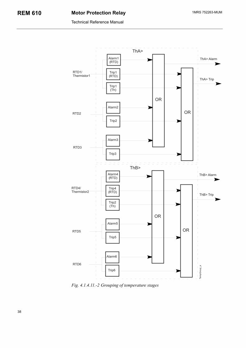
The optional RTD module includes six inputs divided into two groups: RTD1...3 form ThA and RTD4...6 ThB. Inputs RTD1 and RTD4 can also be used with thermistors.
The inputs of ThA can be used for measuring the stator temperature and those of ThB for measuring bearing temperatures and the ambient temperature, for instance.
Each RTD input can be set out of operation. This state will be indicated by dashes on the LCD and by -999 when parameters are read via the SPA bus. When RTD sensors/thermistors are not in use, dashes will be shown on the LCD and -999/999 when parameters are read via serial communication.
Note!
All RTD inputs will automatically be set out of operation when the self-supervision of the RTD module has detected a fault.
Temperature protection using RTD sensorsAn alarm value, Ta1...6>, and a trip value, Tp1...6>, are set for each input separately. When one or several measured temperatures exceed their set alarm values, Ta1...3>/Ta4...6>, stage ThA/ThB will generate an alarm signal on expiration of the set operate time. When one or several measured temperatures exceed their set trip values, Tp1...3>/Tp4...6>, stage ThA>/ThB> will generate a trip signal on expiration of the set operate time.
The alarm signal from ThA>/ThB> will be reset in 800 ms after the temperatures have fallen below their respective set alarm values (Ta1...3>/Ta4...6>) and the trip signal in 800 ms after the temperatures have fallen below their respective set trip values (Tp1...3>/Tp4...6>).
35
1MRS 752263-MUMMotor Protection Relay
Technical Reference Manual
REM 610
Note!
RTD6 can be used to measure the ambient temperature for the thermal protection stage. In this case, Ta6> and Tp6> will not be in use. This state will be indicated by dashes on the LCD and by -999 when the set alarm/trip value is read via the SPA bus.
Note!
For as long as the emergency start is activated, Tp1...6> will be increased by 10 per cent.
Temperature protection using thermistorsREM610 supports PTC thermistors.
When input RTD1/RTD4 is used with thermistors, a trip value, Thp1>/Thp2>, is set for the respective input.
When the resistance of the thermistor exceeds the set trip value, Thp1>/Thp2>, stage ThA>/ThB> will generate a trip signal on expiration of the 2 s fixed operate time.
The trip signal from ThA>/ThB> will be reset in 800 ms after the resistance has fallen below set trip value Thp1>/Thp2>.
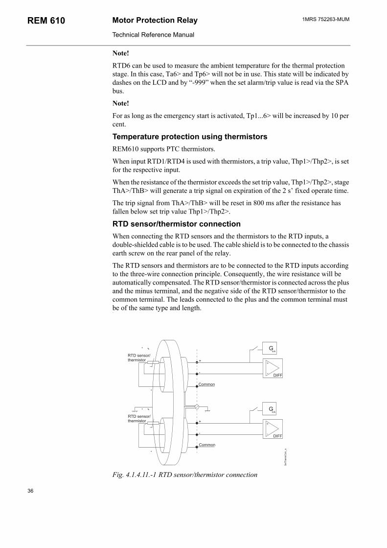
RTD sensor/thermistor connectionWhen connecting the RTD sensors and the thermistors to the RTD inputs, a double-shielded cable is to be used. The cable shield is to be connected to the chassis earth screw on the rear panel of the relay.
The RTD sensors and thermistors are to be connected to the RTD inputs according to the three-wire connection principle. Consequently, the wire resistance will be automatically compensated. The RTD sensor/thermistor is connected across the plus and the minus terminal, and the negative side of the RTD sensor/thermistor to the common terminal. The leads connected to the plus and the common terminal must be of the same type and length.
)*<<*+
<&
+
-
<&
+
-
)*<<*+
99-<)*+/
#9+#*-$9-<'#$*-
#9+#*-$9-<'#$*-
Fig. 4.1.4.11.-1 RTD sensor/thermistor connection
36
1MRS 752263-MUM Motor protection Relay
Technical Reference Manual
REM 610
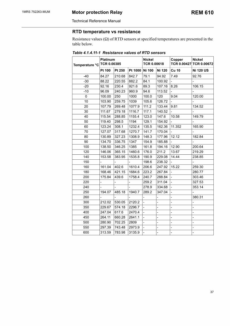
RTD temperature vs resistanceResistance values (Ω) of RTD sensors at specified temperatures are presented in the table below.
Table 4.1.4.11-1 Resistance values of RTD sensors
Temperature °CPlatinum TCR 0.00385
Nickel TCR 0.00618
Copper TCR 0.00427
Nickel TCR 0.00672
Pt 100 Pt 250 Pt 1000 Ni 100 Ni 120 Cu 10 Ni 120 US-40 84.27 210.68 842.7 79.1 94.92 7.49 92.76-30 88.22 220.55 882.2 84.1 100.92 - --20 92.16 230.4 921.6 89.3 107.16 8.26 106.15-10 96.09 240.23 960.9 94.6 113.52 - -0 100.00 250 1000 100.0 120 9.04 120.00
10 103.90 259.75 1039 105.6 126.72 - -20 107.79 269.48 1077.9 111.2 133.44 9.81 134.5230 111.67 279.18 1116.7 117.1 140.52 - -40 115.54 288.85 1155.4 123.0 147.6 10.58 149.7950 119.40 298.5 1194 129.1 154.92 - -60 123.24 308.1 1232.4 135.5 162.36 11.352 165.9070 127.07 317.68 1270.7 141.7 170.04 - -80 130.89 327.23 1308.9 148.3 177.96 12.12 182.8490 134.70 336.75 1347 154.9 185.88 - -
100 138.50 346.25 1385 161.8 194.16 12.90 200.64120 146.06 365.15 1460.6 176.0 211.2 13.67 219.29140 153.58 383.95 1535.8 190.9 229.08 14.44 238.85150 - - - 198.6 238.32 - -160 161.04 402.6 1610.4 206.6 247.92 15.22 259.30180 168.46 421.15 1684.6 223.2 267.84 - 280.77200 175.84 439.6 1758.4 240.7 288.84 - 303.46220 - - - 259.2 311.04 - 327.53240 - - - 278.9 334.68 - 353.14250 194.07 485.18 1940.7 289.2 347.04 - -260 - - - - - - 380.31300 212.02 530.05 2120.2 - - - -350 229.67 574.18 2296.7 - - - -400 247.04 617.6 2470.4 - - - -450 264.11 660.28 2641.1 - - - -500 280.90 702.25 2809 - - - -550 297.39 743.48 2973.9 - - - -600 313.59 783.98 3135.9 - - - -
37
1MRS 752263-MUMMotor Protection Relay
Technical Reference Manual
REM 610
&"
"
9<3-*3/
&
&4-<CD
-'3CD
&4-<
-'3
&4-<
-'3
-'3CD
&"&4-<
&"-'3
&4-<CD
-'3CD
&4-<
-'3
&4-<
-'3
-'3CD
"&4-<
"-'3
9-<'#$*-
9-<'#$*-
Fig. 4.1.4.11.-2 Grouping of temperature stages
38
1MRS 752263-MUM Motor protection Relay
Technical Reference Manual
REM 610
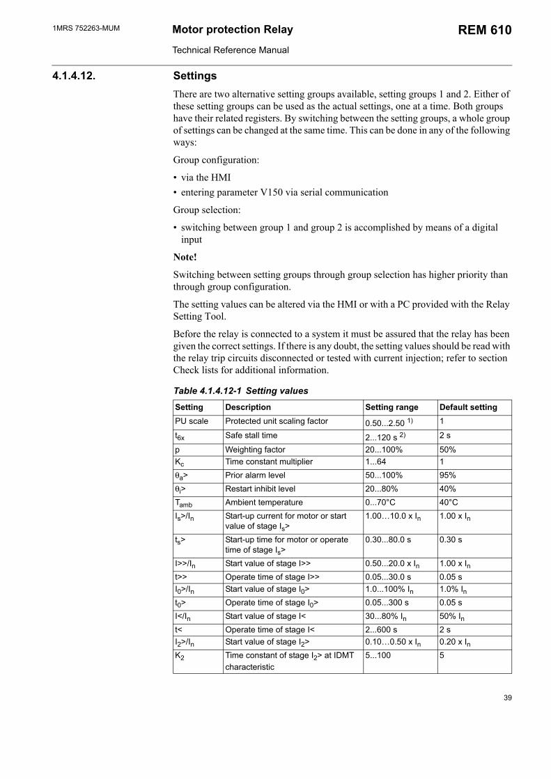
4.1.4.12. SettingsThere are two alternative setting groups available, setting groups 1 and 2. Either of these setting groups can be used as the actual settings, one at a time. Both groups have their related registers. By switching between the setting groups, a whole group of settings can be changed at the same time. This can be done in any of the following ways:
Group configuration:
via the HMI entering parameter V150 via serial communication
Group selection:
switching between group 1 and group 2 is accomplished by means of a digital input
Note!
Switching between setting groups through group selection has higher priority than through group configuration.
The setting values can be altered via the HMI or with a PC provided with the Relay Setting Tool.
Before the relay is connected to a system it must be assured that the relay has been given the correct settings. If there is any doubt, the setting values should be read with the relay trip circuits disconnected or tested with current injection; refer to section Check lists for additional information.
Table 4.1.4.12-1 Setting values
Setting Description Setting range Default settingPU scale Protected unit scaling factor 0.50...2.50 1) 1
t6x Safe stall time 2...120 s 2) 2 s
p Weighting factor 20...100% 50%Kc Time constant multiplier 1...64 1θa> Prior alarm level 50...100% 95%θi> Restart inhibit level 20...80% 40%Tamb Ambient temperature 0...70°C 40°CIs>/In Start-up current for motor or start
value of stage Is>1.0010.0 x In 1.00 x In
ts> Start-up time for motor or operate time of stage Is>
0.30...80.0 s 0.30 s
I>>/In Start value of stage I>> 0.50...20.0 x In 1.00 x Int>> Operate time of stage I>> 0.05...30.0 s 0.05 sI0>/In Start value of stage I0> 1.0...100% In 1.0% Int0> Operate time of stage I0> 0.05...300 s 0.05 sI</In Start value of stage I< 30...80% In 50% Int< Operate time of stage I< 2...600 s 2 sI2>/In Start value of stage I2> 0.100.50 x In 0.20 x InK2 Time constant of stage I2> at IDMT
characteristic5...100 5
39
1MRS 752263-MUMMotor Protection Relay
Technical Reference Manual
REM 610
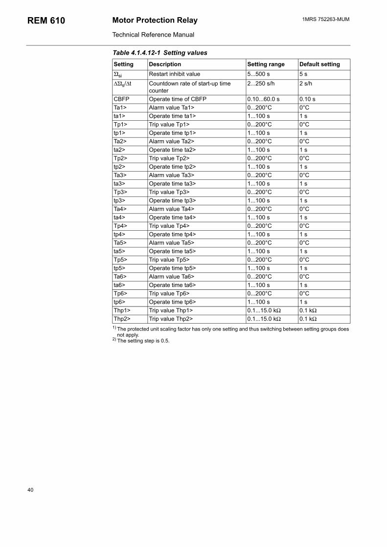
1) The protected unit scaling factor has only one setting and thus switching between setting groups does not apply.
2) The setting step is 0.5.
Σtsi Restart inhibit value 5...500 s 5 s∆Σts/∆t Countdown rate of start-up time
counter2...250 s/h 2 s/h
CBFP Operate time of CBFP 0.10...60.0 s 0.10 sTa1> Alarm value Ta1> 0...200°C 0°Cta1> Operate time ta1> 1...100 s 1 sTp1> Trip value Tp1> 0...200°C 0°Ctp1> Operate time tp1> 1...100 s 1 sTa2> Alarm value Ta2> 0...200°C 0°Cta2> Operate time ta2> 1...100 s 1 sTp2> Trip value Tp2> 0...200°C 0°Ctp2> Operate time tp2> 1...100 s 1 sTa3> Alarm value Ta3> 0...200°C 0°Cta3> Operate time ta3> 1...100 s 1 sTp3> Trip value Tp3> 0...200°C 0°Ctp3> Operate time tp3> 1...100 s 1 sTa4> Alarm value Ta4> 0...200°C 0°Cta4> Operate time ta4> 1...100 s 1 sTp4> Trip value Tp4> 0...200°C 0°Ctp4> Operate time tp4> 1...100 s 1 sTa5> Alarm value Ta5> 0...200°C 0°Cta5> Operate time ta5> 1...100 s 1 sTp5> Trip value Tp5> 0...200°C 0°Ctp5> Operate time tp5> 1...100 s 1 sTa6> Alarm value Ta6> 0...200°C 0°Cta6> Operate time ta6> 1...100 s 1 sTp6> Trip value Tp6> 0...200°C 0°Ctp6> Operate time tp6> 1...100 s 1 sThp1> Trip value Thp1> 0.1...15.0 kΩ 0.1 kΩThp2> Trip value Thp2> 0.1...15.0 kΩ 0.1 kΩ
Table 4.1.4.12-1 Setting values
Setting Description Setting range Default setting
40
1MRS 752263-MUM Motor protection Relay
Technical Reference Manual
REM 610
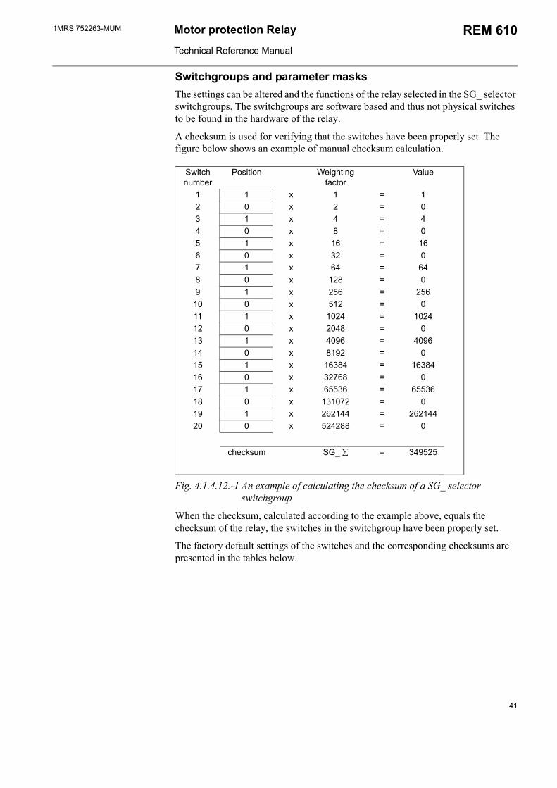
Switchgroups and parameter masksThe settings can be altered and the functions of the relay selected in the SG_ selector switchgroups. The switchgroups are software based and thus not physical switches to be found in the hardware of the relay.
A checksum is used for verifying that the switches have been properly set. The figure below shows an example of manual checksum calculation.
Switch number
Position Weighting factor
Value
1 1 x 1 = 12 0 x 2 = 03 1 x 4 = 44 0 x 8 = 05 1 x 16 = 166 0 x 32 = 07 1 x 64 = 648 0 x 128 = 09 1 x 256 = 25610 0 x 512 = 011 1 x 1024 = 102412 0 x 2048 = 013 1 x 4096 = 409614 0 x 8192 = 015 1 x 16384 = 1638416 0 x 32768 = 017 1 x 65536 = 6553618 0 x 131072 = 019 1 x 262144 = 26214420 0 x 524288 = 0
checksum SG_ ∑ = 349525
Fig. 4.1.4.12.-1 An example of calculating the checksum of a SG_ selector switchgroup
When the checksum, calculated according to the example above, equals the checksum of the relay, the switches in the switchgroup have been properly set.
The factory default settings of the switches and the corresponding checksums are presented in the tables below.
41
1MRS 752263-MUMMotor Protection Relay
Technical Reference Manual
REM 610
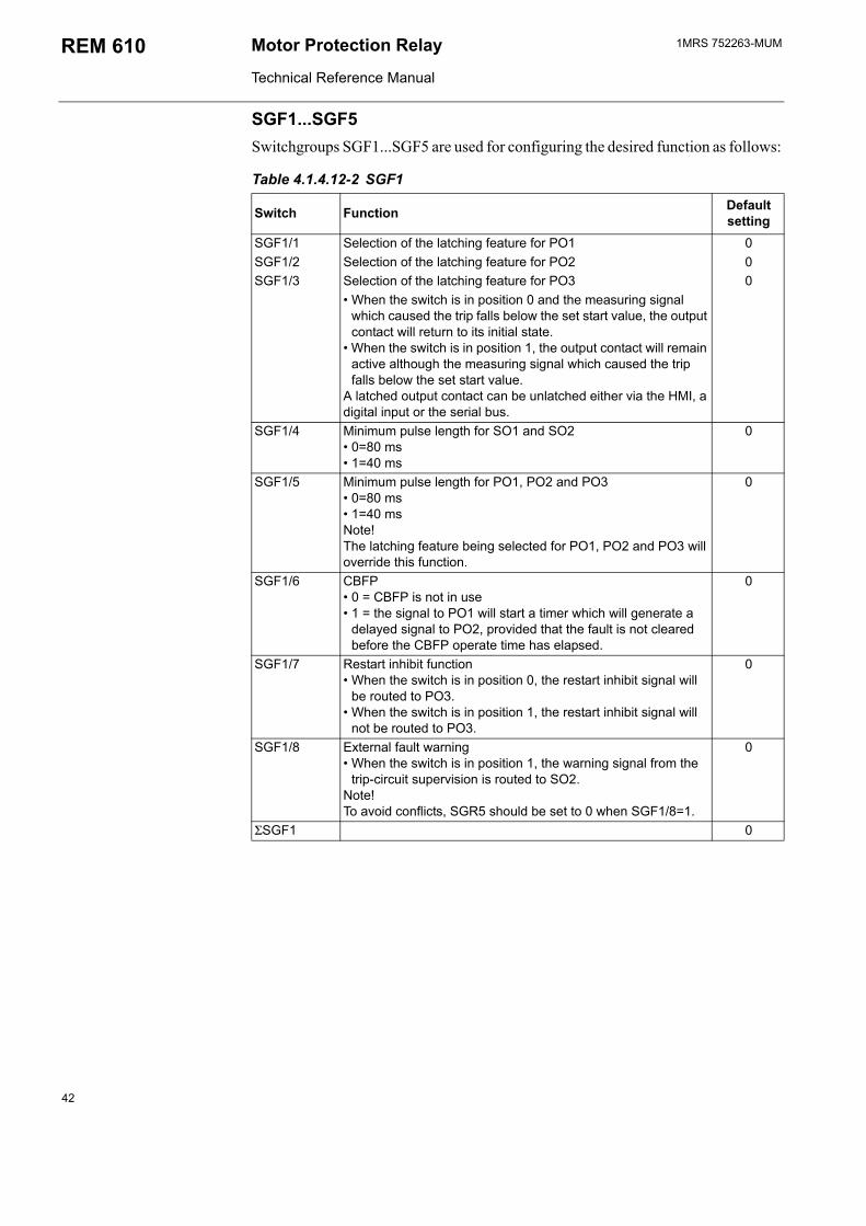
SGF1...SGF5Switchgroups SGF1...SGF5 are used for configuring the desired function as follows:
Table 4.1.4.12-2 SGF1
Switch Function Default setting
SGF1/1 Selection of the latching feature for PO1 0SGF1/2 Selection of the latching feature for PO2 0SGF1/3 Selection of the latching feature for PO3 0
When the switch is in position 0 and the measuring signal which caused the trip falls below the set start value, the output contact will return to its initial state.
When the switch is in position 1, the output contact will remain active although the measuring signal which caused the trip falls below the set start value.
A latched output contact can be unlatched either via the HMI, a digital input or the serial bus.
SGF1/4 Minimum pulse length for SO1 and SO2 0=80 ms 1=40 ms
0
SGF1/5 Minimum pulse length for PO1, PO2 and PO3 0=80 ms 1=40 msNote! The latching feature being selected for PO1, PO2 and PO3 will override this function.
0
SGF1/6 CBFP 0 = CBFP is not in use 1 = the signal to PO1 will start a timer which will generate a
delayed signal to PO2, provided that the fault is not cleared before the CBFP operate time has elapsed.
0
SGF1/7 Restart inhibit function When the switch is in position 0, the restart inhibit signal will
be routed to PO3. When the switch is in position 1, the restart inhibit signal will
not be routed to PO3.
0
SGF1/8 External fault warning When the switch is in position 1, the warning signal from the
trip-circuit supervision is routed to SO2.Note!To avoid conflicts, SGR5 should be set to 0 when SGF1/8=1.
0
ΣSGF1 0
42
1MRS 752263-MUM Motor protection Relay
Technical Reference Manual
REM 610
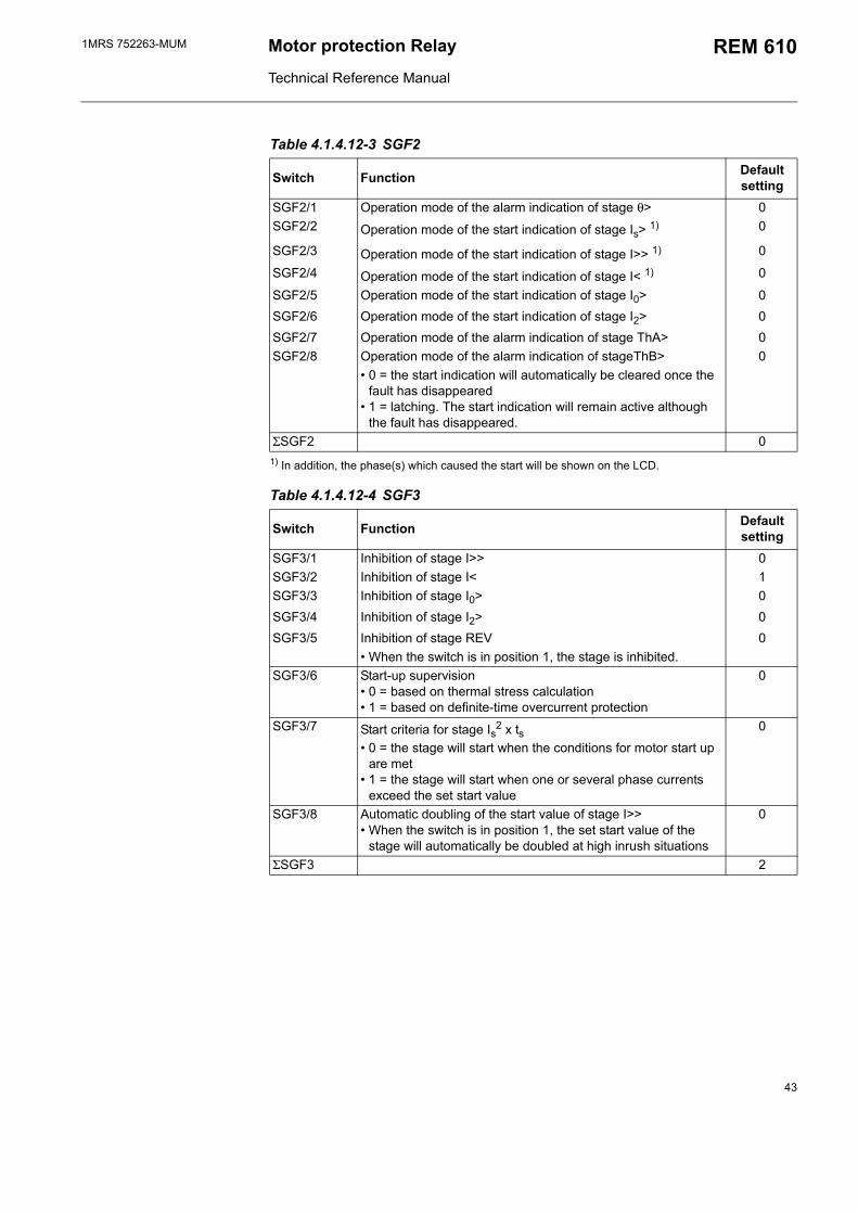
Table 4.1.4.12-3 SGF2
Switch Function Default setting
SGF2/1 Operation mode of the alarm indication of stage θ> 0SGF2/2 Operation mode of the start indication of stage Is> 1) 0
SGF2/3 Operation mode of the start indication of stage I>> 1) 0
SGF2/4 Operation mode of the start indication of stage I< 1) 0
SGF2/5 Operation mode of the start indication of stage I0> 0SGF2/6 Operation mode of the start indication of stage I2> 0SGF2/7 Operation mode of the alarm indication of stage ThA> 0SGF2/8 Operation mode of the alarm indication of stageThB> 0
0 = the start indication will automatically be cleared once the fault has disappeared
1 = latching. The start indication will remain active although the fault has disappeared.
ΣSGF2 01) In addition, the phase(s) which caused the start will be shown on the LCD.
Table 4.1.4.12-4 SGF3
Switch Function Default setting
SGF3/1 Inhibition of stage I>> 0SGF3/2 Inhibition of stage I< 1SGF3/3 Inhibition of stage I0> 0SGF3/4 Inhibition of stage I2> 0SGF3/5 Inhibition of stage REV 0
When the switch is in position 1, the stage is inhibited.SGF3/6 Start-up supervision
0 = based on thermal stress calculation 1 = based on definite-time overcurrent protection
0
SGF3/7 Start criteria for stage Is2 x ts 0 = the stage will start when the conditions for motor start up
are met 1 = the stage will start when one or several phase currents
exceed the set start value
0
SGF3/8 Automatic doubling of the start value of stage I>> When the switch is in position 1, the set start value of the
stage will automatically be doubled at high inrush situations
0
ΣSGF3 2
43
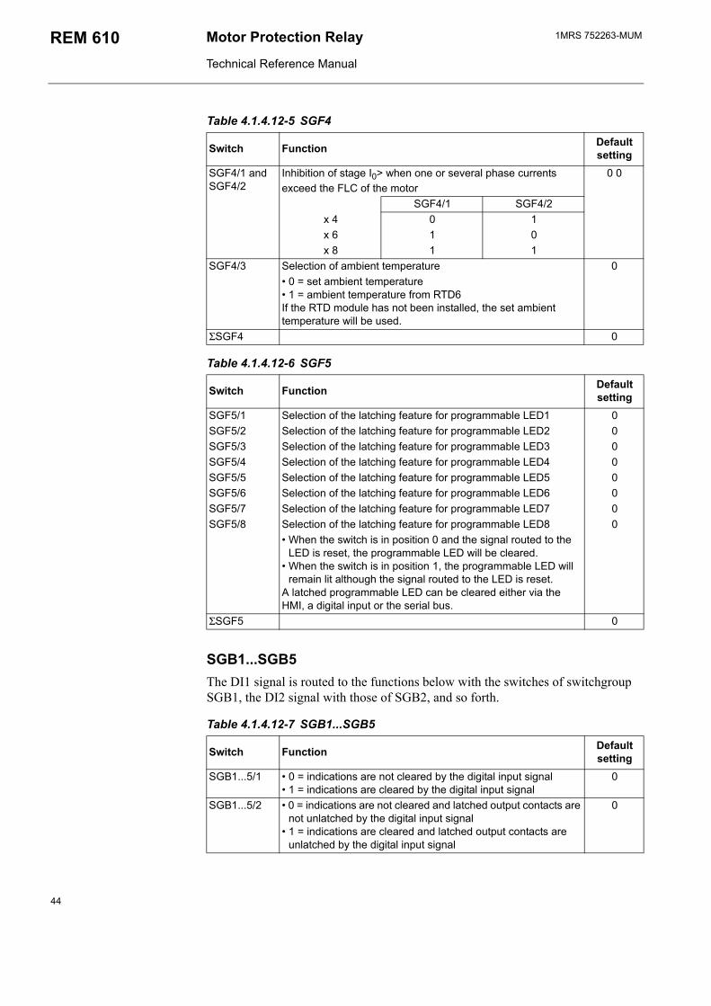
1MRS 752263-MUMMotor Protection Relay
Technical Reference Manual
REM 610
Table 4.1.4.12-5 SGF4
Switch Function Default setting
SGF4/1 and SGF4/2
Inhibition of stage I0> when one or several phase currents exceed the FLC of the motor
0 0
SGF4/1 SGF4/2x 4 0 1x 6 1 0x 8 1 1
SGF4/3 Selection of ambient temperature 0 0 = set ambient temperature 1 = ambient temperature from RTD6 If the RTD module has not been installed, the set ambient temperature will be used.
ΣSGF4 0
Table 4.1.4.12-6 SGF5
Switch Function Default setting
SGF5/1 Selection of the latching feature for programmable LED1 0SGF5/2 Selection of the latching feature for programmable LED2 0SGF5/3 Selection of the latching feature for programmable LED3 0SGF5/4 Selection of the latching feature for programmable LED4 0SGF5/5 Selection of the latching feature for programmable LED5 0SGF5/6 Selection of the latching feature for programmable LED6 0SGF5/7 Selection of the latching feature for programmable LED7 0SGF5/8 Selection of the latching feature for programmable LED8 0
When the switch is in position 0 and the signal routed to the LED is reset, the programmable LED will be cleared.
When the switch is in position 1, the programmable LED will remain lit although the signal routed to the LED is reset.
A latched programmable LED can be cleared either via the HMI, a digital input or the serial bus.
ΣSGF5 0
SGB1...SGB5The DI1 signal is routed to the functions below with the switches of switchgroup SGB1, the DI2 signal with those of SGB2, and so forth.
Table 4.1.4.12-7 SGB1...SGB5
Switch Function Default setting
SGB1...5/1 0 = indications are not cleared by the digital input signal 1 = indications are cleared by the digital input signal
0
SGB1...5/2 0 = indications are not cleared and latched output contacts are not unlatched by the digital input signal
1 = indications are cleared and latched output contacts are unlatched by the digital input signal
0
44
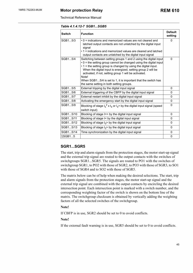
1MRS 752263-MUM Motor protection Relay
Technical Reference Manual
REM 610
SGR1...SGR5The start, trip and alarm signals from the protection stages, the motor start-up signal and the external trip signal are routed to the output contacts with the switches of switchgroups SGR1...SGR5. The signals are routed to PO1 with the switches of switchgroup SGR1, to PO2 with those of SGR2, to PO3 with those of SGR3, to SO1 with those of SGR4 and to SO2 with those of SGR5.
The matrix below can be of help when making the desired selections. The start, trip and alarm signals from the protection stages, the motor start-up signal and the external trip signal are combined with the output contacts by encircling the desired intersection point. Each intersection point is marked with a switch number, and the corresponding weighting factor of the switch is shown on the bottom line of the matrix. The switchgroup checksum is obtained by vertically adding the weighting factors of all the selected switches of the switchgroup.
Note!
If CBFP is in use, SGR2 should be set to 0 to avoid conflicts.
Note!
If the external fault warning is in use, SGR5 should be set to 0 to avoid conflicts.
SGB1...5/3 0 = indications and memorized values are not cleared and latched output contacts are not unlatched by the digital input signal
1 = indications and memorized values are cleared and latched output contacts are unlatched by the digital input signal
0
SGB1...5/4 Switching between setting groups 1 and 2 using the digital input 0 = the setting group cannot be changed using the digital input 1 = the setting group is changed by using the digital input.
When the digital input is energized, setting group 2 will be activated, if not, setting group 1 will be activated.
Note!When SGB1...5/4 is set to 1, it is important that the switch has the same setting in both setting groups.
0
SGB1...5/5 External tripping by the digital input signal 0SGB1...5/6 External triggering of the CBFP by the digital input signal 0SGB1...5/7 External restart inhibit by the digital input signal 0SGB1...5/8 Activating the emergency start by the digital input signal 0SGB1...5/9 Blocking of stage Is2 x ts or Is> by the digital input signal (speed
switch input)
0
SGB1...5/10 Blocking of stage I>> by the digital input signal 0SGB1...5/11 Blocking of stage I< by the digital input signal 0SGB1...5/12 Blocking of stage I0> by the digital input signal 0SGB1...5/13 Blocking of stage I2> by the digital input signal 0SGB1...5/14 Time synchronization by the digital input signal 0ΣSGB1...5 0
Table 4.1.4.12-7 SGB1...SGB5
Switch Function Default setting
45
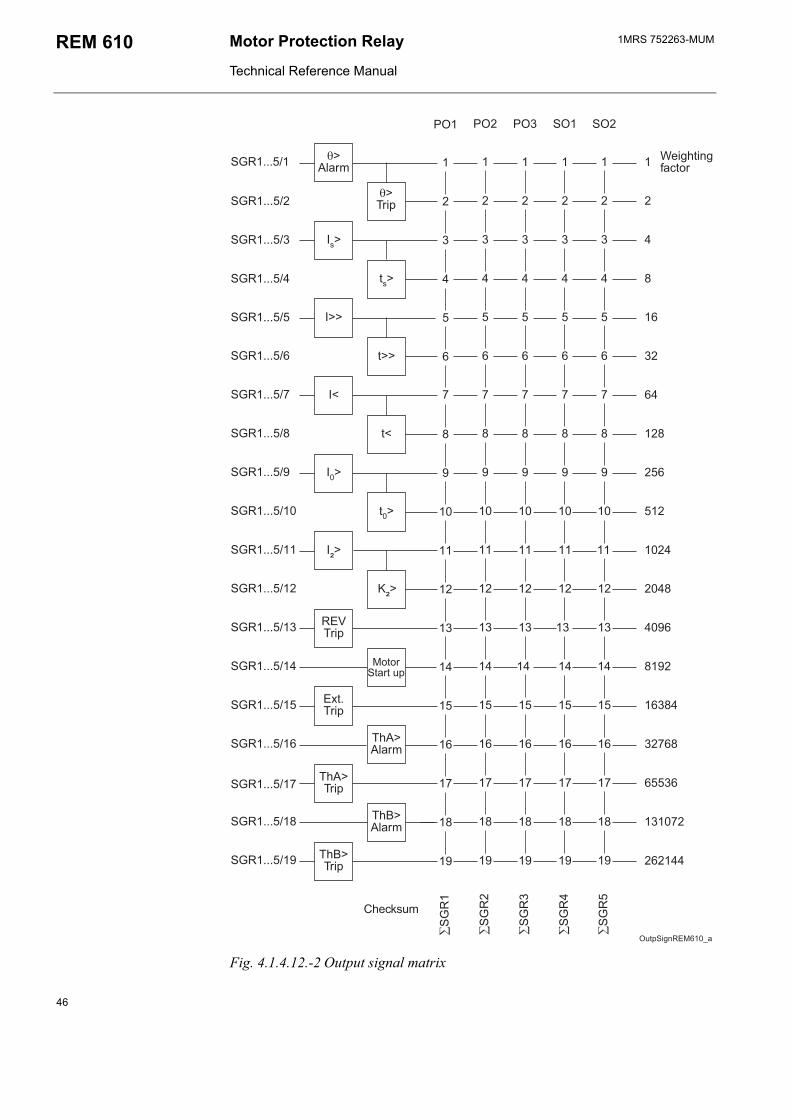
1MRS 752263-MUMMotor Protection Relay
Technical Reference Manual
REM 610
,- #- ,- ,- #-
#.(
/ ////
#.(
#.(
#.(
/ ////
#.(
#.(
#.(
#.(
#.(/
#.(
#.(/
#.(
#.(
#.(
#.(
#.(
#.(
#.(
#.(
/
/
#.(
#.(
#.(
#.(
#.(
-!%#&0(12
3
3
4
4
5&0&06)
)7!"
8"
(19:&%
1:&%
:88"
2#!%
:&%
:8:&%
:;8"
:;:&%
Fig. 4.1.4.12.-2 Output signal matrix
46
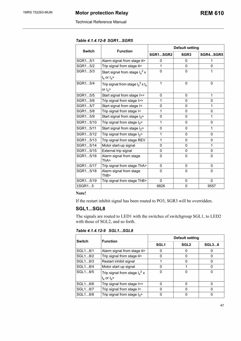
1MRS 752263-MUM Motor protection Relay
Technical Reference Manual
REM 610
Table 4.1.4.12-8 SGR1...SGR5
Switch FunctionDefault setting
SGR1...SGR2 SGR3 SGR4...SGR5SGR1...5/1 Alarm signal from stage θ> 0 0 1SGR1...5/2 Trip signal from stage θ> 1 0 0SGR1...5/3 Start signal from stage Is2 x
ts or Is>
0 0 1
SGR1...5/4 Trip signal from stage Is2 x ts or Is>
1 0 0
SGR1...5/5 Start signal from stage I>> 0 0 1SGR1...5/6 Trip signal from stage I>> 1 0 0SGR1...5/7 Start signal from stage I< 0 0 1SGR1...5/8 Trip signal from stage I< 1 0 0SGR1...5/9 Start signal from stage I0> 0 0 1SGR1...5/10 Trip signal from stage I0> 1 0 0SGR1...5/11 Start signal from stage I2> 0 0 1SGR1...5/12 Trip signal from stage I2> 1 0 0SGR1...5/13 Trip signal from stage REV 1 0 0SGR1...5/14 Motor start-up signal 0 0 1SGR1...5/15 External trip signal 0 0 0SGR1...5/16 Alarm signal from stage
ThA>0 0 0
SGR1...5/17 Trip signal from stage ThA> 0 0 0SGR1...5/18 Alarm signal from stage
ThB>0 0 0
SGR1...5/19 Trip signal from stage ThB> 0 0 0ΣSGR1...5 6826 0 9557
Note!
If the restart inhibit signal has been routed to PO3, SGR3 will be overridden.
SGL1...SGL8 The signals are routed to LED1 with the switches of switchgroup SGL1, to LED2 with those of SGL2, and so forth.
Table 4.1.4.12-9 SGL1...SGL8
Switch FunctionDefault setting
SGL1 SGL2 SGL3...8SGL1...8/1 Alarm signal from stage θ> 0 0 0SGL1...8/2 Trip signal from stage θ> 0 0 0SGL1...8/3 Restart inhibit signal 1 0 0SGL1...8/4 Motor start up signal 0 1 0SGL1...8/5 Trip signal from stage Is2 x
ts or Is>
0 0 0
SGL1...8/6 Trip signal from stage I>> 0 0 0SGL1...8/7 Trip signal from stage I< 0 0 0SGL1...8/8 Trip signal from stage I0> 0 0 0
47
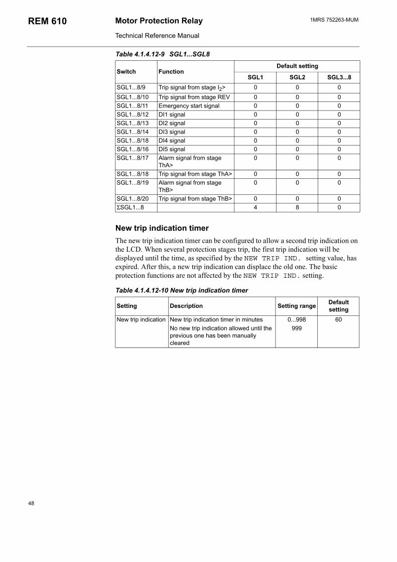
1MRS 752263-MUMMotor Protection Relay
Technical Reference Manual
REM 610
New trip indication timerThe new trip indication timer can be configured to allow a second trip indication on the LCD. When several protection stages trip, the first trip indication will be displayed until the time, as specified by the NEW TRIP IND. setting value, has expired. After this, a new trip indication can displace the old one. The basic protection functions are not affected by the NEW TRIP IND. setting.
Table 4.1.4.12-10 New trip indication timer
Setting Description Setting range Default setting
New trip indication New trip indication timer in minutes 0...998 60No new trip indication allowed until the previous one has been manually cleared
999
SGL1...8/9 Trip signal from stage I2> 0 0 0SGL1...8/10 Trip signal from stage REV 0 0 0SGL1...8/11 Emergency start signal 0 0 0SGL1...8/12 DI1 signal 0 0 0SGL1...8/13 DI2 signal 0 0 0SGL1...8/14 DI3 signal 0 0 0SGL1...8/18 DI4 signal 0 0 0SGL1...8/16 DI5 signal 0 0 0SGL1...8/17 Alarm signal from stage
ThA>0 0 0
SGL1...8/18 Trip signal from stage ThA> 0 0 0SGL1...8/19 Alarm signal from stage
ThB>0 0 0
SGL1...8/20 Trip signal from stage ThB> 0 0 0ΣSGL1...8 4 8 0
Table 4.1.4.12-9 SGL1...SGL8
Switch FunctionDefault setting
SGL1 SGL2 SGL3...8
48
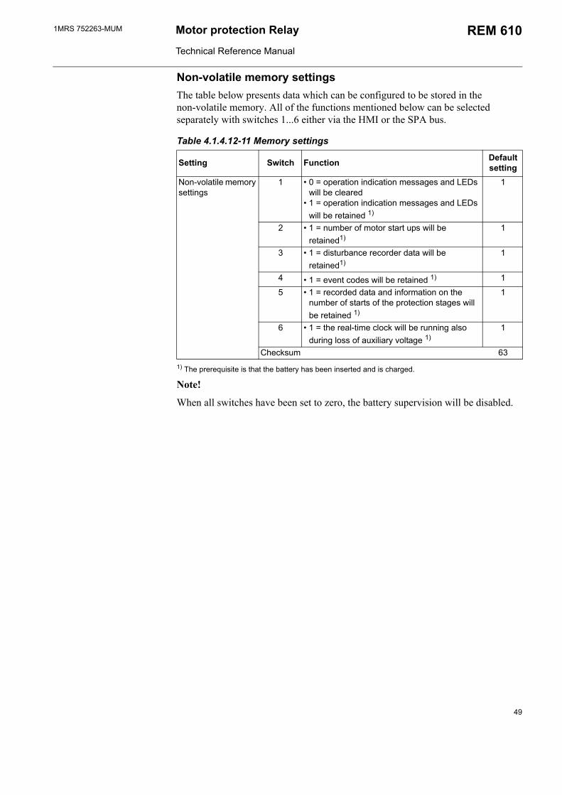
1MRS 752263-MUM Motor protection Relay
Technical Reference Manual
REM 610
Non-volatile memory settingsThe table below presents data which can be configured to be stored in the non-volatile memory. All of the functions mentioned below can be selected separately with switches 1...6 either via the HMI or the SPA bus.
Table 4.1.4.12-11 Memory settings
Setting Switch Function Default setting
Non-volatile memory settings
1 0 = operation indication messages and LEDs will be cleared
1 = operation indication messages and LEDs will be retained 1)
1
2 1 = number of motor start ups will be retained1)
1
3 1 = disturbance recorder data will be retained1)
1
4 1 = event codes will be retained 1) 1
5 1 = recorded data and information on the number of starts of the protection stages will be retained 1)
1
6 1 = the real-time clock will be running also during loss of auxiliary voltage 1)
1
Checksum 631) The prerequisite is that the battery has been inserted and is charged.
Note!
When all switches have been set to zero, the battery supervision will be disabled.
49
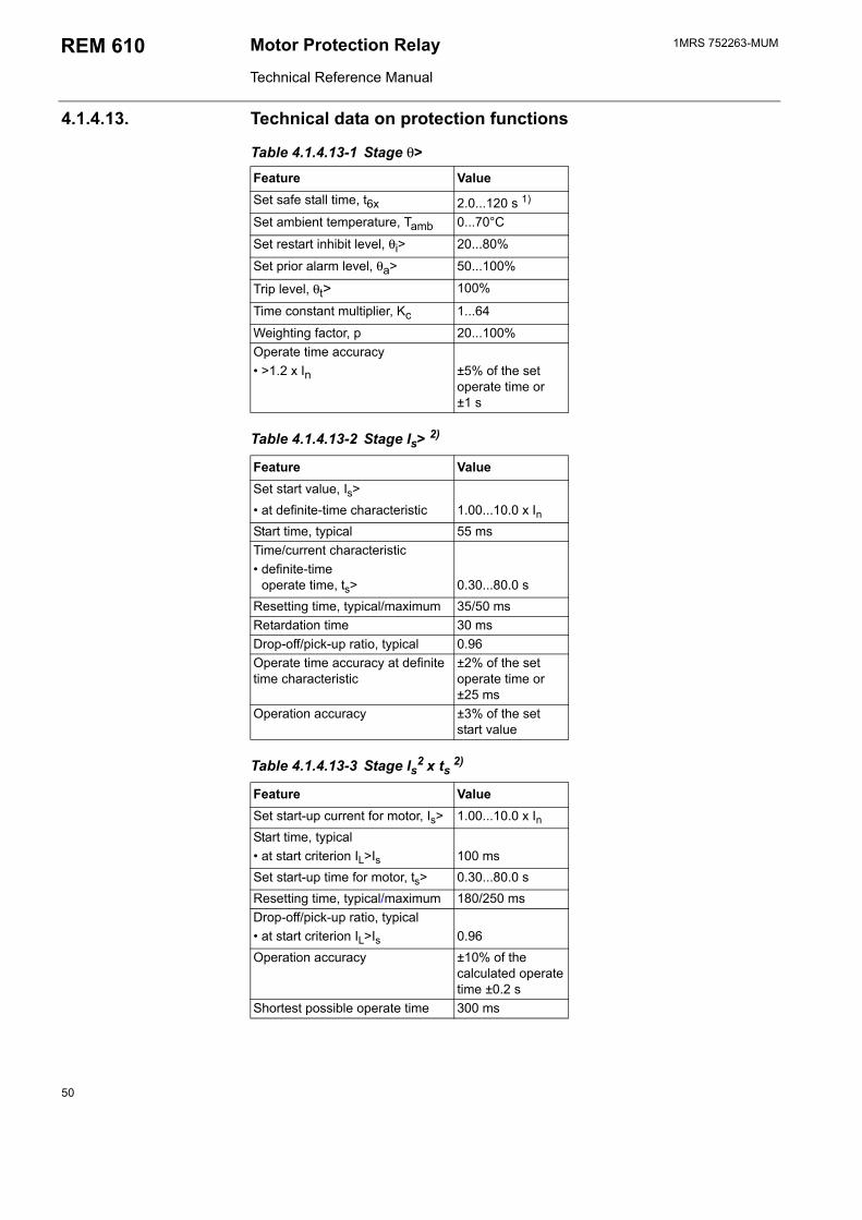
1MRS 752263-MUMMotor Protection Relay
Technical Reference Manual
REM 610
4.1.4.13. Technical data on protection functions
Table 4.1.4.13-1 Stage θ>
Feature ValueSet safe stall time, t6x 2.0...120 s 1)
Set ambient temperature, Tamb 0...70°C
Set restart inhibit level, θi> 20...80%
Set prior alarm level, θa> 50...100%
Trip level, θt> 100%
Time constant multiplier, Kc 1...64
Weighting factor, p 20...100%Operate time accuracy >1.2 x In ±5% of the set
operate time or ±1 s
Table 4.1.4.13-2 Stage Is> 2)
Feature ValueSet start value, Is> at definite-time characteristic 1.00...10.0 x InStart time, typical 55 msTime/current characteristic definite-time
operate time, ts> 0.30...80.0 s
Resetting time, typical/maximum 35/50 msRetardation time 30 msDrop-off/pick-up ratio, typical 0.96Operate time accuracy at definite time characteristic
±2% of the set operate time or ±25 ms
Operation accuracy ±3% of the set start value
Table 4.1.4.13-3 Stage Is2 x ts 2)
Feature ValueSet start-up current for motor, Is> 1.00...10.0 x InStart time, typical at start criterion IL>Is 100 msSet start-up time for motor, ts> 0.30...80.0 sResetting time, typical/maximum 180/250 msDrop-off/pick-up ratio, typical at start criterion IL>Is 0.96Operation accuracy ±10% of the
calculated operate time ±0.2 s
Shortest possible operate time 300 ms
50
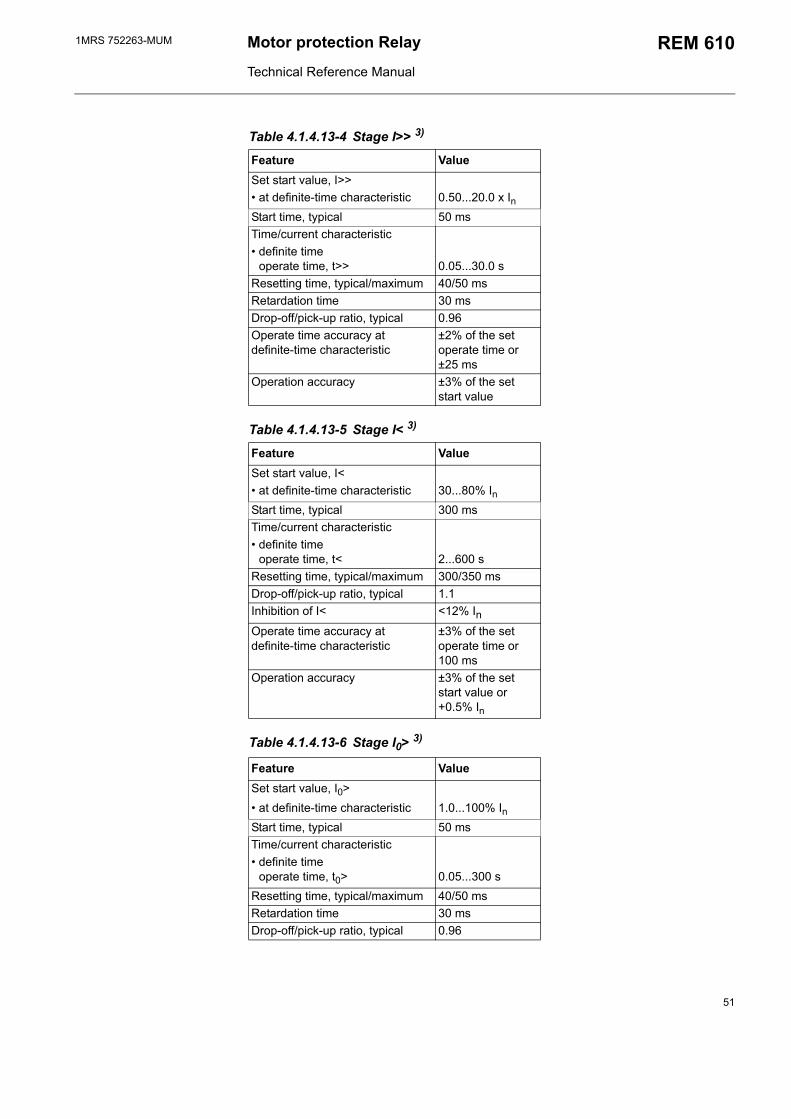
1MRS 752263-MUM Motor protection Relay
Technical Reference Manual
REM 610
Table 4.1.4.13-4 Stage I>> 3)
Feature ValueSet start value, I>> at definite-time characteristic 0.50...20.0 x InStart time, typical 50 msTime/current characteristic definite time
operate time, t>> 0.05...30.0 s
Resetting time, typical/maximum 40/50 msRetardation time 30 msDrop-off/pick-up ratio, typical 0.96Operate time accuracy at definite-time characteristic
±2% of the set operate time or ±25 ms
Operation accuracy ±3% of the set start value
Table 4.1.4.13-5 Stage I< 3)
Feature ValueSet start value, I< at definite-time characteristic 30...80% InStart time, typical 300 msTime/current characteristic definite time
operate time, t< 2...600 s
Resetting time, typical/maximum 300/350 msDrop-off/pick-up ratio, typical 1.1Inhibition of I< <12% InOperate time accuracy at definite-time characteristic
±3% of the set operate time or 100 ms
Operation accuracy ±3% of the set start value or+0.5% In
Table 4.1.4.13-6 Stage I0> 3)
Feature ValueSet start value, I0> at definite-time characteristic 1.0...100% InStart time, typical 50 msTime/current characteristic definite time
operate time, t0> 0.05...300 s
Resetting time, typical/maximum 40/50 msRetardation time 30 msDrop-off/pick-up ratio, typical 0.96
51
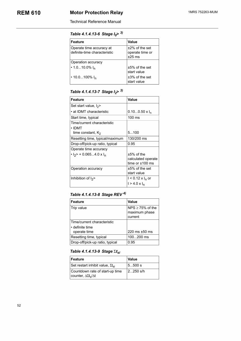
1MRS 752263-MUMMotor Protection Relay
Technical Reference Manual
REM 610
Operate time accuracy at definite-time characteristic
±2% of the set operate time or ±25 ms
Operation accuracy 1.0...10.0% In ±5% of the set
start value 10.0...100% In ±3% of the set
start value
Table 4.1.4.13-7 Stage I2> 3)
Feature ValueSet start value, I2> at IDMT characteristic 0.10...0.50 x InStart time, typical 100 msTime/current characteristic IDMT
time constant, K2
5...100
Resetting time, typical/maximum 130/200 msDrop-off/pick-up ratio, typical 0.95Operate time accuracy I2> + 0.065...4.0 x In ±5% of the
calculated operate time or ±100 ms
Operation accuracy ±5% of the set start value
Inhibition of I2> I < 0.12 x In or I > 4.0 x In
Table 4.1.4.13-8 Stage REV 4)
Feature ValueTrip value NPS ≥ 75% of the
maximum phase current
Time/current characteristic definite time
operate time 220 ms ±50 ms
Resetting time, typical 100...200 msDrop-off/pick-up ratio, typical 0.95
Table 4.1.4.13-9 Stage Σtsi
Feature ValueSet restart inhibit value, Σtsi 5...500 sCountdown rate of start-up time counter, ∆Σts/∆t
2...250 s/h
Table 4.1.4.13-6 Stage I0> 3)
Feature Value
52
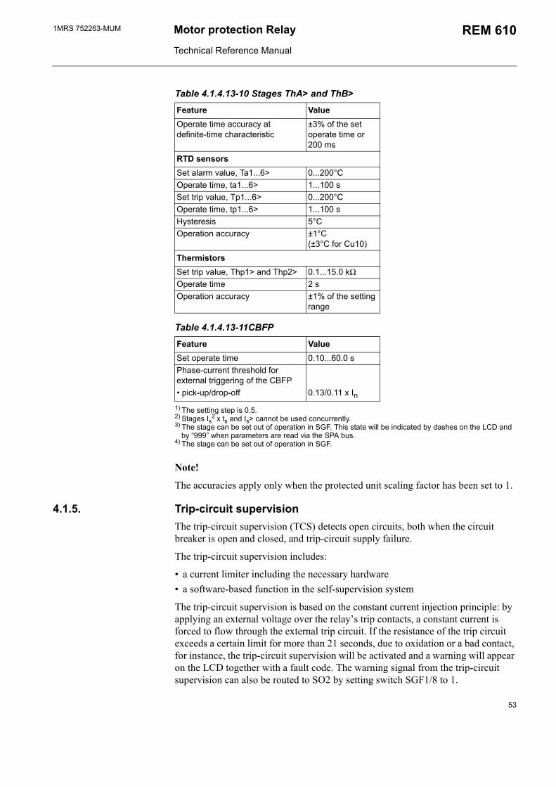
1MRS 752263-MUM Motor protection Relay
Technical Reference Manual
REM 610
Table 4.1.4.13-10 Stages ThA> and ThB>
Feature ValueOperate time accuracy at definite-time characteristic
±3% of the set operate time or 200 ms
RTD sensorsSet alarm value, Ta1...6> 0...200°COperate time, ta1...6> 1...100 sSet trip value, Tp1...6> 0...200°COperate time, tp1...6> 1...100 sHysteresis 5°COperation accuracy ±1°C
(±3°C for Cu10)
ThermistorsSet trip value, Thp1> and Thp2> 0.1...15.0 kΩOperate time 2 sOperation accuracy ±1% of the setting
range
Table 4.1.4.13-11CBFP
Feature ValueSet operate time 0.10...60.0 sPhase-current threshold for external triggering of the CBFP pick-up/drop-off 0.13/0.11 x In
1) The setting step is 0.5.2) Stages Is2 x ts and Is> cannot be used concurrently.3) The stage can be set out of operation in SGF. This state will be indicated by dashes on the LCD and
by 999 when parameters are read via the SPA bus.4) The stage can be set out of operation in SGF.
Note!
The accuracies apply only when the protected unit scaling factor has been set to 1.
4.1.5. Trip-circuit supervisionThe trip-circuit supervision (TCS) detects open circuits, both when the circuit breaker is open and closed, and trip-circuit supply failure.
The trip-circuit supervision includes:
a current limiter including the necessary hardware a software-based function in the self-supervision system
The trip-circuit supervision is based on the constant current injection principle: by applying an external voltage over the relays trip contacts, a constant current is forced to flow through the external trip circuit. If the resistance of the trip circuit exceeds a certain limit for more than 21 seconds, due to oxidation or a bad contact, for instance, the trip-circuit supervision will be activated and a warning will appear on the LCD together with a fault code. The warning signal from the trip-circuit supervision can also be routed to SO2 by setting switch SGF1/8 to 1.
53
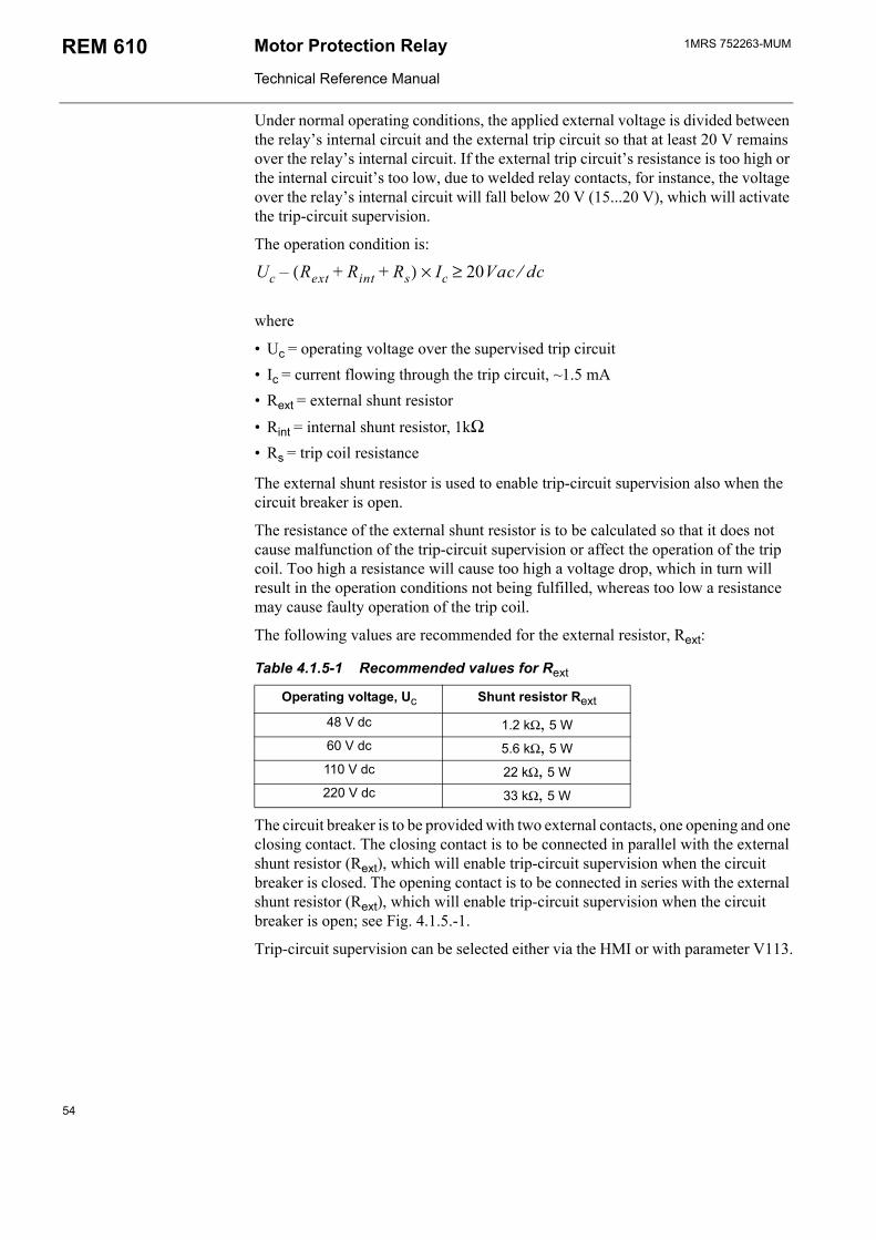
1MRS 752263-MUMMotor Protection Relay
Technical Reference Manual
REM 610
Under normal operating conditions, the applied external voltage is divided between the relays internal circuit and the external trip circuit so that at least 20 V remains over the relays internal circuit. If the external trip circuits resistance is too high or the internal circuits too low, due to welded relay contacts, for instance, the voltage over the relays internal circuit will fall below 20 V (15...20 V), which will activate the trip-circuit supervision.
The operation condition is:
Uc Rext Rint Rs+ +( ) Ic 20Vac dc⁄≥×
where
Uc = operating voltage over the supervised trip circuit Ic = current flowing through the trip circuit, ~1.5 mA Rext = external shunt resistor
Rint = internal shunt resistor, 1kΩ Rs = trip coil resistance
The external shunt resistor is used to enable trip-circuit supervision also when the circuit breaker is open.
The resistance of the external shunt resistor is to be calculated so that it does not cause malfunction of the trip-circuit supervision or affect the operation of the trip coil. Too high a resistance will cause too high a voltage drop, which in turn will result in the operation conditions not being fulfilled, whereas too low a resistance may cause faulty operation of the trip coil.
The following values are recommended for the external resistor, Rext:
Table 4.1.5-1 Recommended values for Rext
Operating voltage, Uc Shunt resistor Rext
48 V dc 1.2 kΩ, 5 W60 V dc 5.6 kΩ, 5 W110 V dc 22 kΩ, 5 W220 V dc 33 kΩ, 5 W
The circuit breaker is to be provided with two external contacts, one opening and one closing contact. The closing contact is to be connected in parallel with the external shunt resistor (Rext), which will enable trip-circuit supervision when the circuit breaker is closed. The opening contact is to be connected in series with the external shunt resistor (Rext), which will enable trip-circuit supervision when the circuit breaker is open; see Fig. 4.1.5.-1.
Trip-circuit supervision can be selected either via the HMI or with parameter V113.
54
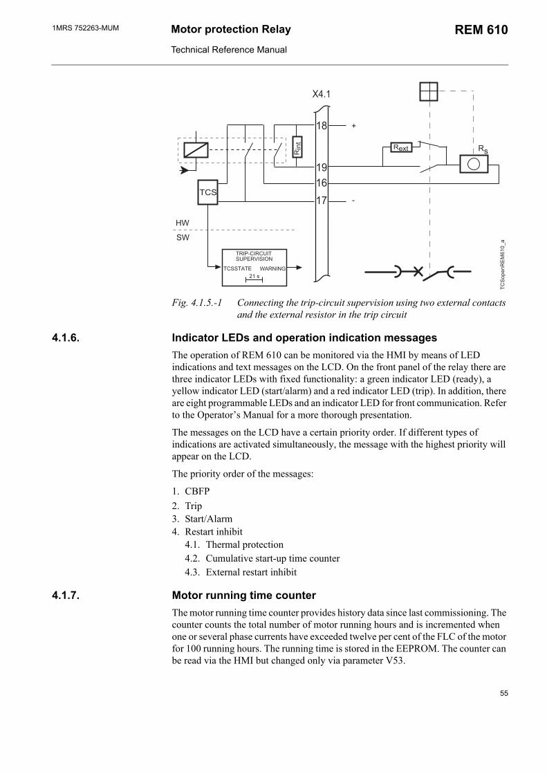
1MRS 752263-MUM Motor protection Relay
Technical Reference Manual
REM 610
"
#
$
%
&'(
) *+,
,-
,!,+
,.
/ 0,
)1
,$
&
&&
&
2# &2 3&
Fig. 4.1.5.-1 Connecting the trip-circuit supervision using two external contacts and the external resistor in the trip circuit
4.1.6. Indicator LEDs and operation indication messagesThe operation of REM 610 can be monitored via the HMI by means of LED indications and text messages on the LCD. On the front panel of the relay there are three indicator LEDs with fixed functionality: a green indicator LED (ready), a yellow indicator LED (start/alarm) and a red indicator LED (trip). In addition, there are eight programmable LEDs and an indicator LED for front communication. Refer to the Operators Manual for a more thorough presentation.
The messages on the LCD have a certain priority order. If different types of indications are activated simultaneously, the message with the highest priority will appear on the LCD.
The priority order of the messages:
1. CBFP2. Trip3. Start/Alarm4. Restart inhibit
4.1. Thermal protection4.2. Cumulative start-up time counter4.3. External restart inhibit
4.1.7. Motor running time counterThe motor running time counter provides history data since last commissioning. The counter counts the total number of motor running hours and is incremented when one or several phase currents have exceeded twelve per cent of the FLC of the motor for 100 running hours. The running time is stored in the EEPROM. The counter can be read via the HMI but changed only via parameter V53.
55

1MRS 752263-MUMMotor Protection Relay
Technical Reference Manual
REM 610
Note!
Writing to parameter V53 will reset the number of motor start ups.
4.1.8. Monitoring of demand valuesREM 610 provides three different kinds of demand values. The first value shows the average current of all three phases measured during one minute. The value is updated once a minute. The second value shows the average current during an adjustable time range, ranging from 0 to 999 minutes, with an accuracy of one minute. This value is updated at the expiration of each time range. The third value shows the highest one-minute average current value measured during the previous time range. However, if the time range is set to zero, only the one-minute and the maximum demand value will be shown. The maximum value is the highest one-minute mean value since the last reset.
The demand values can be set to zero by resetting the relay or through communication using a V parameter. The demand values will also be reset if V105 is changed.
4.1.9. Commissioning testsThe following two product functions can be used during the commissioning of the relay: function test and digital input test.
The function test is used for testing the configuration as well as the connections from the relay. By selecting this test, the internal signals from the protection stages, the motor start-up signal, the external trip signal and the IRF function can be activated one by one. Provided that the signals have been set to be routed to the output contacts (PO1, PO2, PO3, SO1 and SO2) with the switches of SGR1...5, the output contacts will be activated and their corresponding event codes generated when the test is run. However, activation of the internal signals from the protection stages, the motor start-up signal, the external trip signal and the IRF function will not generate an event code.
The digital input test is used for testing the connections to the relay. The state of the digital inputs can be monitored via the HMI.
Refer to the Operators Manual for more detailed instructions on how to perform the tests.
4.1.10. Disturbance recorder
4.1.10.1. FunctionREM 610 features an integrated disturbance recorder for recording monitored quantities. The recorder continuously captures the curve forms of the currents as well as the status of both internal and digital input signals and stores these in the memory.
Triggering of the recorder will generate an event code. After the recorder has been triggered, it will continue to record data for a pre-defined post-triggering time. An asterisk will be shown on the LCD on completion of the recording. The status of the recording can also be viewed using SPA parameter V246.
56
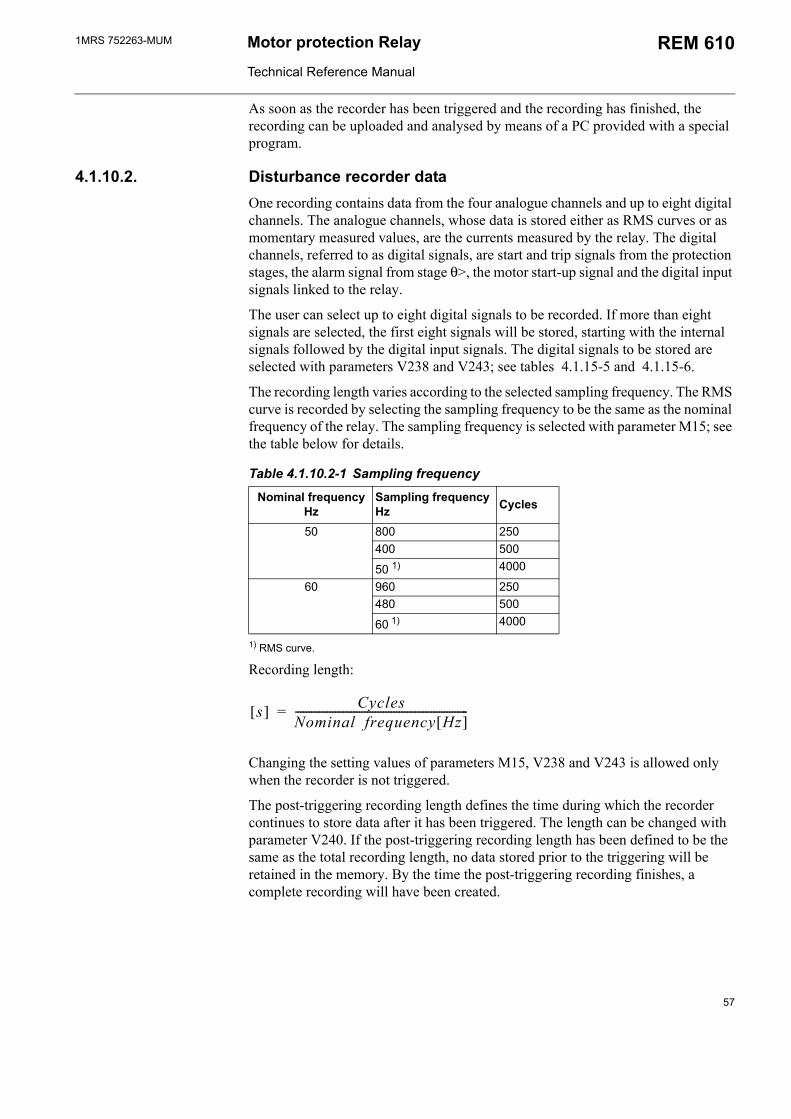
1MRS 752263-MUM Motor protection Relay
Technical Reference Manual
REM 610
As soon as the recorder has been triggered and the recording has finished, the recording can be uploaded and analysed by means of a PC provided with a special program.
4.1.10.2. Disturbance recorder dataOne recording contains data from the four analogue channels and up to eight digital channels. The analogue channels, whose data is stored either as RMS curves or as momentary measured values, are the currents measured by the relay. The digital channels, referred to as digital signals, are start and trip signals from the protection stages, the alarm signal from stage θ>, the motor start-up signal and the digital input signals linked to the relay.
The user can select up to eight digital signals to be recorded. If more than eight signals are selected, the first eight signals will be stored, starting with the internal signals followed by the digital input signals. The digital signals to be stored are selected with parameters V238 and V243; see tables 4.1.15-5 and 4.1.15-6.
The recording length varies according to the selected sampling frequency. The RMS curve is recorded by selecting the sampling frequency to be the same as the nominal frequency of the relay. The sampling frequency is selected with parameter M15; see the table below for details.
Table 4.1.10.2-1 Sampling frequency
Nominal frequencyHz
Sampling frequency Hz Cycles
50 800 250400 500
50 1) 4000
60 960 250480 500
60 1) 4000
1) RMS curve.
Recording length:
s[ ] Cycles
Nominal frequency Hz[ ]-----------------------------------------------------------------=
Changing the setting values of parameters M15, V238 and V243 is allowed only when the recorder is not triggered.
The post-triggering recording length defines the time during which the recorder continues to store data after it has been triggered. The length can be changed with parameter V240. If the post-triggering recording length has been defined to be the same as the total recording length, no data stored prior to the triggering will be retained in the memory. By the time the post-triggering recording finishes, a complete recording will have been created.
57
1MRS 752263-MUMMotor Protection Relay
Technical Reference Manual
REM 610
Triggering of the recorder immediately after it has been cleared or the auxiliary voltage connected may result in a shortened total recording length. Disconnection of the auxiliary voltage after the recorder has been triggered but before the recording has finished, on the other hand, may result in a shortened post-triggering recording length. This, however, will not affect the total recording length.
At a power reset, triggered recorder data will be retained in the memory provided that it has been defined non-volatile.
4.1.10.3. Control and indication of disturbance recorder statusIt is possible to control and monitor the recording status of the disturbance recorder by writing to and reading parameters M1, M2 and V246. Reading parameter V246 will return either the value 0 or 1, indicating whether the recorder has not been triggered or triggered and ready to be uploaded. Event code E31 will be generated the moment the disturbance recorder is triggered. If the recorder is ready to be uploaded, this will also be indicated by an asterisk shown in the lower right-hand corner of the LCD when it is in the idle mode.
Writing the value 1 to parameter M2 will clear the recorder memory, restart the storing of new data and enable the triggering of the recorder. Recorder data can be cleared by performing a master reset, i.e. clearing indications and memorized values and unlatching output contacts. Writing the value 2 to parameter V246 will restart the unloading process by setting the time stamp and the first data ready to be read.
4.1.10.4. TriggeringThe user can select one or several internal or digital input signals to trigger the disturbance recorder, either on the rising or falling edge of the signal(s). Triggering on the rising edge means that the post-triggering recording sequence will start when the signal is activated. Correspondingly, triggering on the falling edge means that the post-triggering recording sequence will start when the active signal is reset. The trigger signal(s) and the edge are selected with parameters V236...V237 and V241...V242; see tables 4.1.15-5 and 4.1.15-6. The recorder can also be triggered manually using parameter M1.
Triggering of the disturbance recorder is only possible if the recorder has not already been triggered.
4.1.10.5. Settings and unloadingThe setting parameters for the disturbance recorder are V parameters V236...V238, V240...V243 and V246, and M parameters M15, M18, M20 and M80...M83.
Unloading correct information from the recorder requires that M80 and M83 have been set. Unloading is done using a PC application. The uploaded recorder data is stored in separate files defined by the comtrade format.
4.1.10.6. Event code of the disturbance recorderThe disturbance recorder generates an event code on triggering (E31) and clearing (E32) the recorder. The event mask is determined using SPA parameter V155.
58
1MRS 752263-MUM Motor protection Relay
Technical Reference Manual
REM 610
4.1.11. Recorded data of the last eventsREM 610 records up to five events. This enables the user to analyse the last five fault conditions in the motor drive controller. Each event includes the measured currents, start durations and time stamp, for instance. Additionally, information on the number of starts is provided.
Recorded data is non-volatile by default, provided that the battery has been inserted and is charged. A master reset, i.e. clearing of indications and memorized values and unlatching of output contacts, will erase the contents of the stored events and the number of starts.
REM 610 collects data during fault conditions and motor start ups. When all start or alarm signals have been reset, a stage trips or the motor start up has ended, the collected data and time stamp will be stored as EVENT1 and the previously stored events will move one step forward. When a sixth event is stored, the oldest event will be cleared.
59
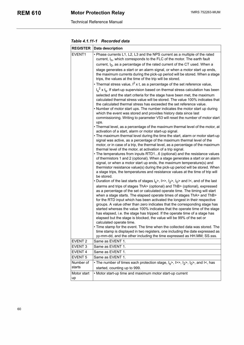
1MRS 752263-MUMMotor Protection Relay
Technical Reference Manual
REM 610
Table 4.1.11-1 Recorded data
REGISTER Data descriptionEVENT1 Phase currents L1, L2, L3 and the NPS current as a multiple of the rated
current, In, which corresponds to the FLC of the motor. The earth fault current, I0, as a percentage of the rated current of the CT used. When a stage generates a start or an alarm signal, or when a motor start up ends, the maximum currents during the pick-up period will be stored. When a stage trips, the values at the time of the trip will be stored.
Thermal stress value, I2 x t, as a percentage of the set reference value, Is
2 x ts. If start-up supervision based on thermal stress calculation has been selected and the start criteria for the stage have been met, the maximum calculated thermal stress value will be stored. The value 100% indicates that the calculated thermal stress has exceeded the set reference value.
Number of motor start ups. The number indicates the motor start up during which the event was stored and provides history data since last commissioning. Writing to parameter V53 will reset the number of motor start ups.
Thermal level, as a percentage of the maximum thermal level of the motor, at activation of a start, alarm or motor start-up signal.
The maximum thermal level during the time the start, alarm or motor start-up signal was active, as a percentage of the maximum thermal level of the motor, or in case of a trip, the thermal level, as a percentage of the maximum thermal level of the motor, at activation of a trip signal.
The temperatures from inputs RTD1...6 (optional) and the resistance values of thermistors 1 and 2 (optional). When a stage generates a start or an alarm signal, or when a motor start up ends, the maximum temperature(s) and thermistor resistance value(s) during the pick-up period will be stored. When a stage trips, the temperatures and resistance values at the time of trip will be stored.
Duration of the last starts of stages Is>, I>>, I2>, I0> and I<, and of the last alarms and trips of stages ThA> (optional) and ThB> (optional), expressed as a percentage of the set or calculated operate time. The timing will start when a stage starts. The elapsed operate times of stages ThA> and ThB> for the RTD input which has been activated the longest in their respective groups. A value other than zero indicates that the corresponding stage has started whereas the value 100% indicates that the operate time of the stage has elapsed, i.e. the stage has tripped. If the operate time of a stage has elapsed but the stage is blocked, the value will be 99% of the set or calculated operate time.
Time stamp for the event. The time when the collected data was stored. The time stamp is displayed in two registers, one including the date expressed as yy-mm-dd, and the other including the time expressed as HH.MM; SS.sss.
EVENT 2 Same as EVENT 1.EVENT 3 Same as EVENT 1.EVENT 4 Same as EVENT 1.EVENT 5 Same as EVENT 1.Number of starts
The number of times each protection stage, Is>, I>>, I2>, I0>, and I<, has started, counting up to 999.
Motor start up
Motor start-up time and maximum motor start-up current
60
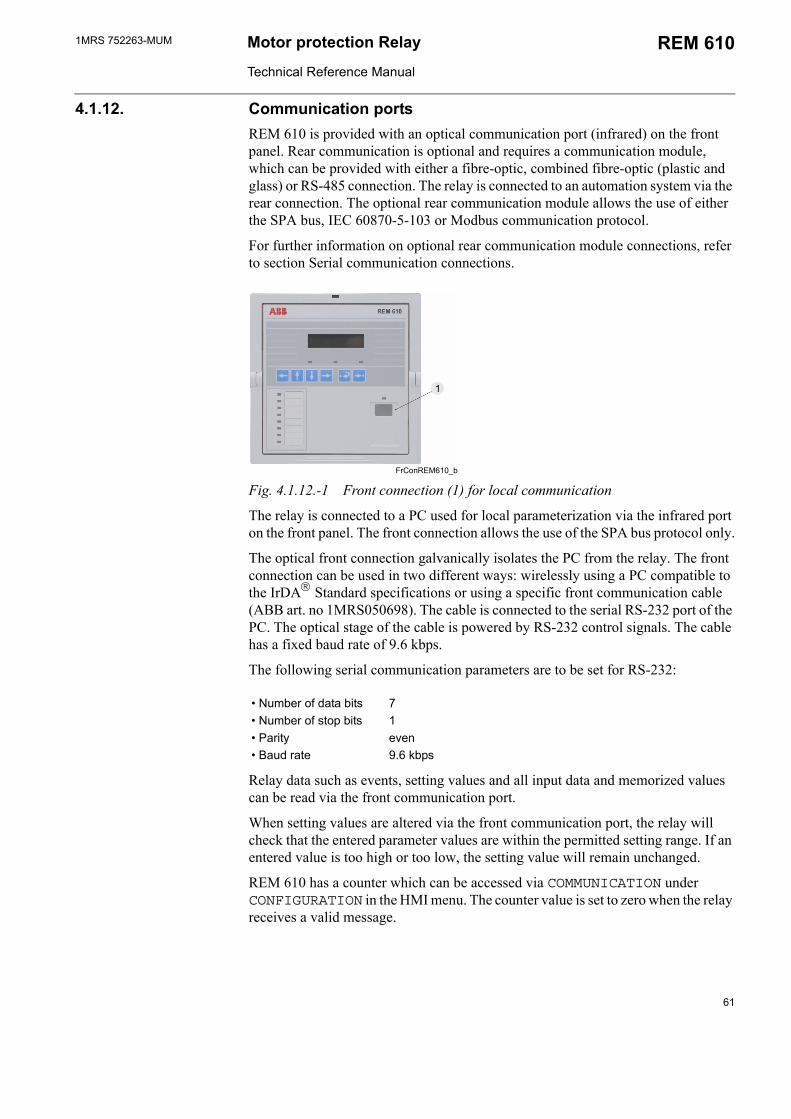
1MRS 752263-MUM Motor protection Relay
Technical Reference Manual
REM 610
4.1.12. Communication portsREM 610 is provided with an optical communication port (infrared) on the front panel. Rear communication is optional and requires a communication module, which can be provided with either a fibre-optic, combined fibre-optic (plastic and glass) or RS-485 connection. The relay is connected to an automation system via the rear connection. The optional rear communication module allows the use of either the SPA bus, IEC 60870-5-103 or Modbus communication protocol.
For further information on optional rear communication module connections, refer to section Serial communication connections.
FrConREM610_b
Fig. 4.1.12.-1 Front connection (1) for local communication
The relay is connected to a PC used for local parameterization via the infrared port on the front panel. The front connection allows the use of the SPA bus protocol only.
The optical front connection galvanically isolates the PC from the relay. The front connection can be used in two different ways: wirelessly using a PC compatible to the IrDA Standard specifications or using a specific front communication cable (ABB art. no 1MRS050698). The cable is connected to the serial RS-232 port of the PC. The optical stage of the cable is powered by RS-232 control signals. The cable has a fixed baud rate of 9.6 kbps.
The following serial communication parameters are to be set for RS-232:
Number of data bits 7 Number of stop bits 1 Parity even Baud rate 9.6 kbps
Relay data such as events, setting values and all input data and memorized values can be read via the front communication port.
When setting values are altered via the front communication port, the relay will check that the entered parameter values are within the permitted setting range. If an entered value is too high or too low, the setting value will remain unchanged.
REM 610 has a counter which can be accessed via COMMUNICATION under CONFIGURATION in the HMI menu. The counter value is set to zero when the relay receives a valid message.
61
1MRS 752263-MUMMotor Protection Relay
Technical Reference Manual
REM 610
4.1.13. IEC 60870-5-103 remote communication protocolREM 610 supports the IEC 60870-5-103 remote communication protocol (henceforward referred to as the IEC_103) in the unbalanced transmission mode. The IEC_103 protocol is used to transfer measurand and status data from the slave to the master. However, the IEC_103 protocol cannot be used to transfer disturbance recorder data.
The IEC_103 protocol can be used only through the rear connection of the relay on the optional communication module. Connecting REM 610 to a fibre-optic communication bus requires a fibre-optic communication module. The line-idle state of the fibre-optic communication module can be selected either via the HMI or the SPA bus. According to the IEC_103 standard, however, the line-idle state is light on. To ensure communication, the line-idle state should be the same for both the master and the slave device. The connection topology can be selected to be either loop or star, the default being loop, and either via the HMI or the SPA bus. The selected line-idle state and connection topology apply irrespective of which rear communication protocol is active.
REM 610 will use the SPA bus protocol as default when the optional communication module is in use. The protocol selection is memorized and will therefore always be activated when the rear connection is in use. The baud rate can be selected either via the HMI or the SPA bus. According to the IEC_103 standard, however, the baud rate is 9.6 kbps. When the IEC_103 protocol is active, event masks are not in use. Consequently, all events in the selected configuration set will be included in the event reporting.
REM 610 is provided with two different selectable configuration sets, of which configuration set 1 is used by default. Configuration set 1 is intended to be used when the optional RTD module has not been installed. Configuration set 2 includes additional information, e.g. temperature protection events and digital input events 3...5, provided that the optional RTD module has been installed. Function type and information number have been mapped into configuration sets according to the IEC_103 standard to the extent that these have been defined by the standard. If not defined by the standard, the type of function and/or the information number have/has been mapped into a private range.
The tables below indicate the information mapping of the corresponding configuration sets. The column GI indicates whether the status of the specified information object is transmitted within the general interrogation cycle. The relative time in messages with the type identification 2 is calculated as a time difference between the occurred event and the event specified in the column Relative time. The measurand multiplied by the normalize factor is proportional to the rated value. Therefore, the maximum value of each measurand is the normalize factor multiplied by the rated value.
62

1MRS 752263-MUM Motor protection Relay
Technical Reference Manual
REM 610
Table 4.1.13-1 Information mapping of configuration set 1 and 2
Event reason
Even
t cod
e
Con
figur
atio
n se
t 1
Con
figur
atio
n se
t 2
Func
tion
ty
pe
Info
rmat
ion
nu
mbe
r
GI
Rel
ativ
e
time
Type
id
entif
icat
ion
Emergency start Activated/Reset
E5/E6 X X 11 31 X - 1
Disturbance recorder Triggered/Cleared
E31/E32
X X 178 100 - - 1
HMI Password Opened/Closed
E33/E34
X X 178 101 - - 1
Motor start up Begins/Ends
1E1/1E2
X X 178 84 X 1E1 2
θ> Start/Reset 1E3/1E4
X X 184 84 X 1E3 2
θ> Alarm/Reset 1E5/1E6
X X 184 11 X 1E3 2
θ> Trip/Reset 1E7/1E8
X X 184 90 - 1E3 2
θ> Restart Inhibit/Reset
1E9/1E10
X X 184 30 X 1E3 2
Σtsi Restart Inhibit/Reset
1E11/1E12
X X 178 30 X - 1
Restart Inhibit/Reset 1E13/1E14
X X 11 30 X - 1
Is2 x ts/Is> Start/Reset 1E15/1E16
X X 160 84 X 1E15 2
Is2 x ts/Is>Trip/Reset 1E17/1E18
X X 160 1)
(178)90 - 1E15 2
I>> Start/Reset 1E19/1E20
X X 162 94 X 1E19 2
I>> Trip/Reset 1E21/1E22
X X 160 91 - 1E19 2
I< Start/Reset 1E23/1E24
X X 20 84 X 1E23 2
I< Trip/Reset 1E25/1E26
X X 20 90 - 1E23 2
I0> Start/Reset 1E27/1E28
X X 160 67 X 1E27 2
I0> Trip/Reset 1E29/1E30
X X 160 92 - 1E27 2
I2> Start/Reset 1E31/1E32
X X 21 84 X 1E31 2
63
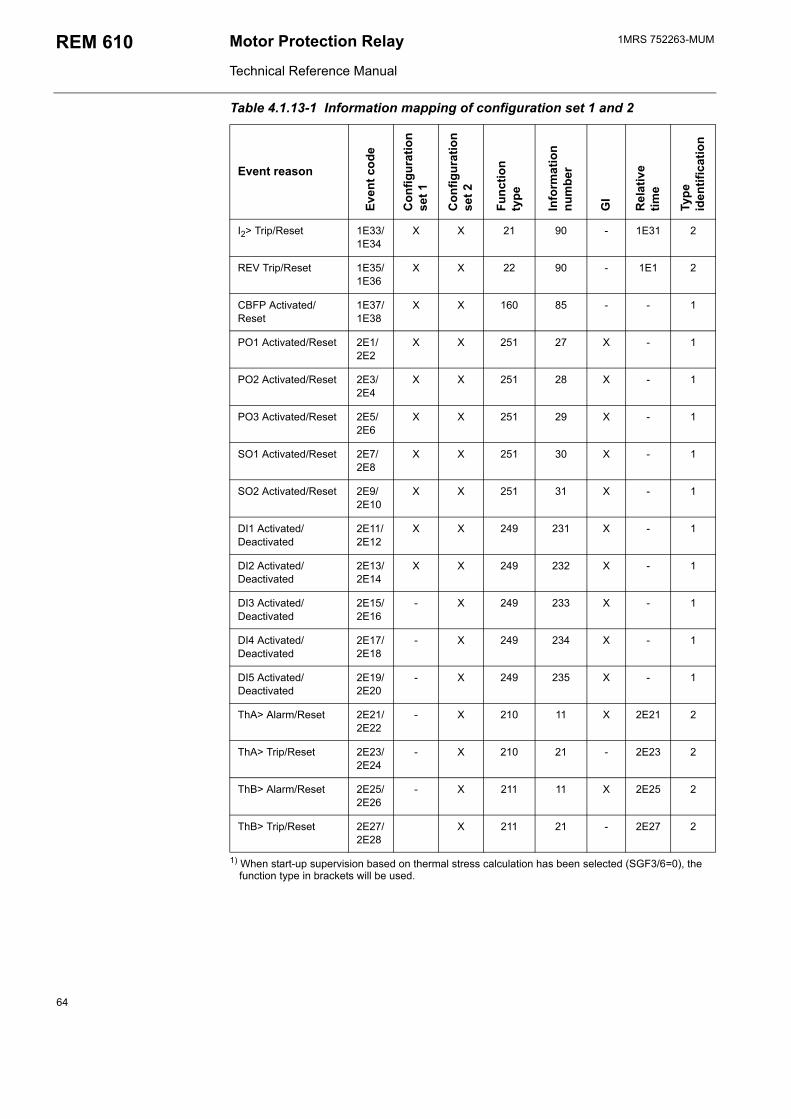
1MRS 752263-MUMMotor Protection Relay
Technical Reference Manual
REM 610
1) When start-up supervision based on thermal stress calculation has been selected (SGF3/6=0), the function type in brackets will be used.
I2> Trip/Reset 1E33/1E34
X X 21 90 - 1E31 2
REV Trip/Reset 1E35/1E36
X X 22 90 - 1E1 2
CBFP Activated/Reset
1E37/1E38
X X 160 85 - - 1
PO1 Activated/Reset 2E1/2E2
X X 251 27 X - 1
PO2 Activated/Reset 2E3/2E4
X X 251 28 X - 1
PO3 Activated/Reset 2E5/2E6
X X 251 29 X - 1
SO1 Activated/Reset 2E7/2E8
X X 251 30 X - 1
SO2 Activated/Reset 2E9/2E10
X X 251 31 X - 1
DI1 Activated/Deactivated
2E11/2E12
X X 249 231 X - 1
DI2 Activated/Deactivated
2E13/2E14
X X 249 232 X - 1
DI3 Activated/Deactivated
2E15/2E16
- X 249 233 X - 1
DI4 Activated/Deactivated
2E17/2E18
- X 249 234 X - 1
DI5 Activated/Deactivated
2E19/2E20
- X 249 235 X - 1
ThA> Alarm/Reset 2E21/2E22
- X 210 11 X 2E21 2
ThA> Trip/Reset 2E23/2E24
- X 210 21 - 2E23 2
ThB> Alarm/Reset 2E25/2E26
- X 211 11 X 2E25 2
ThB> Trip/Reset 2E27/2E28
X 211 21 - 2E27 2
Table 4.1.13-1 Information mapping of configuration set 1 and 2
Event reason
Even
t cod
e
Con
figur
atio
n se
t 1
Con
figur
atio
n se
t 2
Func
tion
ty
pe
Info
rmat
ion
nu
mbe
r
GI
Rel
ativ
e
time
Type
id
entif
icat
ion
64
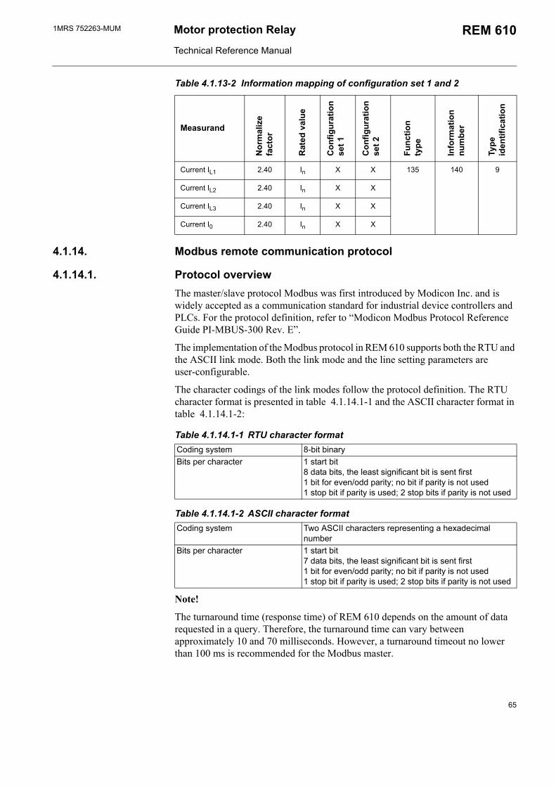
1MRS 752263-MUM Motor protection Relay
Technical Reference Manual
REM 610
Table 4.1.13-2 Information mapping of configuration set 1 and 2
Measurand
Nor
mal
ize
fa
ctor
Rat
ed v
alue
Con
figur
atio
n se
t 1
Con
figur
atio
n se
t 2
Func
tion
ty
pe
Info
rmat
ion
nu
mbe
r
Type
id
entif
icat
ion
Current IL1 2.40 In X X 135 140 9
Current IL2 2.40 In X X
Current IL3 2.40 In X X
Current I0 2.40 In X X
4.1.14. Modbus remote communication protocol
4.1.14.1. Protocol overviewThe master/slave protocol Modbus was first introduced by Modicon Inc. and is widely accepted as a communication standard for industrial device controllers and PLCs. For the protocol definition, refer to Modicon Modbus Protocol Reference Guide PI-MBUS-300 Rev. E.
The implementation of the Modbus protocol in REM 610 supports both the RTU and the ASCII link mode. Both the link mode and the line setting parameters are user-configurable.
The character codings of the link modes follow the protocol definition. The RTU character format is presented in table 4.1.14.1-1 and the ASCII character format in table 4.1.14.1-2:
Table 4.1.14.1-1 RTU character formatCoding system 8-bit binaryBits per character 1 start bit
8 data bits, the least significant bit is sent first1 bit for even/odd parity; no bit if parity is not used1 stop bit if parity is used; 2 stop bits if parity is not used
Table 4.1.14.1-2 ASCII character formatCoding system Two ASCII characters representing a hexadecimal
numberBits per character 1 start bit
7 data bits, the least significant bit is sent first1 bit for even/odd parity; no bit if parity is not used1 stop bit if parity is used; 2 stop bits if parity is not used
Note!
The turnaround time (response time) of REM 610 depends on the amount of data requested in a query. Therefore, the turnaround time can vary between approximately 10 and 70 milliseconds. However, a turnaround timeout no lower than 100 ms is recommended for the Modbus master.
65
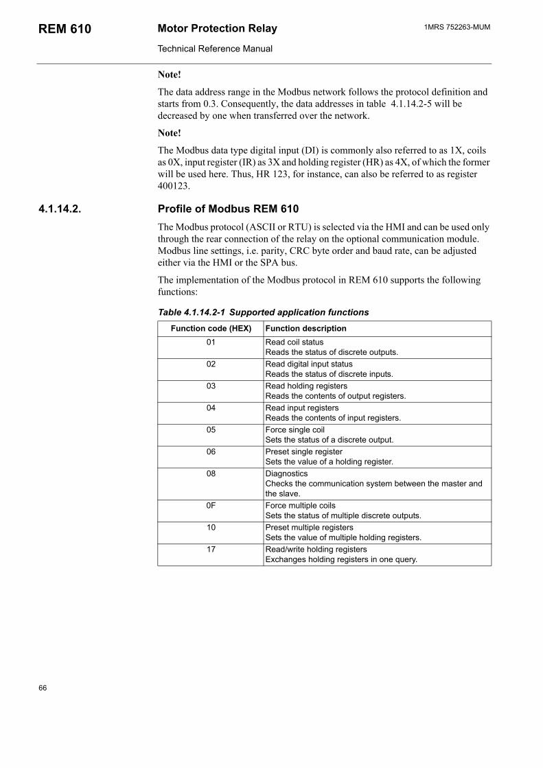
1MRS 752263-MUMMotor Protection Relay
Technical Reference Manual
REM 610
Note!
The data address range in the Modbus network follows the protocol definition and starts from 0.3. Consequently, the data addresses in table 4.1.14.2-5 will be decreased by one when transferred over the network.
Note!
The Modbus data type digital input (DI) is commonly also referred to as 1X, coils as 0X, input register (IR) as 3X and holding register (HR) as 4X, of which the former will be used here. Thus, HR 123, for instance, can also be referred to as register 400123.
4.1.14.2. Profile of Modbus REM 610The Modbus protocol (ASCII or RTU) is selected via the HMI and can be used only through the rear connection of the relay on the optional communication module. Modbus line settings, i.e. parity, CRC byte order and baud rate, can be adjusted either via the HMI or the SPA bus.
The implementation of the Modbus protocol in REM 610 supports the following functions:
Table 4.1.14.2-1 Supported application functions
Function code (HEX) Function description01 Read coil status
Reads the status of discrete outputs.02 Read digital input status
Reads the status of discrete inputs.03 Read holding registers
Reads the contents of output registers.04 Read input registers
Reads the contents of input registers.05 Force single coil
Sets the status of a discrete output.06 Preset single register
Sets the value of a holding register.08 Diagnostics
Checks the communication system between the master and the slave.
0F Force multiple coilsSets the status of multiple discrete outputs.
10 Preset multiple registersSets the value of multiple holding registers.
17 Read/write holding registersExchanges holding registers in one query.
66
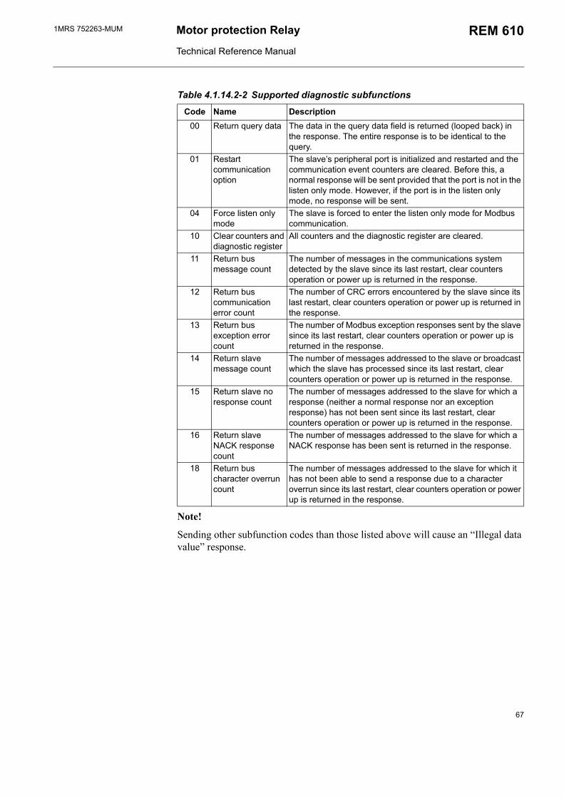
1MRS 752263-MUM Motor protection Relay
Technical Reference Manual
REM 610
Table 4.1.14.2-2 Supported diagnostic subfunctions
Code Name Description00 Return query data The data in the query data field is returned (looped back) in
the response. The entire response is to be identical to the query.
01 Restart communication option
The slaves peripheral port is initialized and restarted and the communication event counters are cleared. Before this, a normal response will be sent provided that the port is not in the listen only mode. However, if the port is in the listen only mode, no response will be sent.
04 Force listen only mode
The slave is forced to enter the listen only mode for Modbus communication.
10 Clear counters and diagnostic register
All counters and the diagnostic register are cleared.
11 Return bus message count
The number of messages in the communications system detected by the slave since its last restart, clear counters operation or power up is returned in the response.
12 Return bus communication error count
The number of CRC errors encountered by the slave since its last restart, clear counters operation or power up is returned in the response.
13 Return bus exception error count
The number of Modbus exception responses sent by the slave since its last restart, clear counters operation or power up is returned in the response.
14 Return slave message count
The number of messages addressed to the slave or broadcast which the slave has processed since its last restart, clear counters operation or power up is returned in the response.
15 Return slave no response count
The number of messages addressed to the slave for which a response (neither a normal response nor an exception response) has not been sent since its last restart, clear counters operation or power up is returned in the response.
16 Return slave NACK response count
The number of messages addressed to the slave for which a NACK response has been sent is returned in the response.
18 Return bus character overrun count
The number of messages addressed to the slave for which it has not been able to send a response due to a character overrun since its last restart, clear counters operation or power up is returned in the response.
Note!
Sending other subfunction codes than those listed above will cause an Illegal data value response.
67
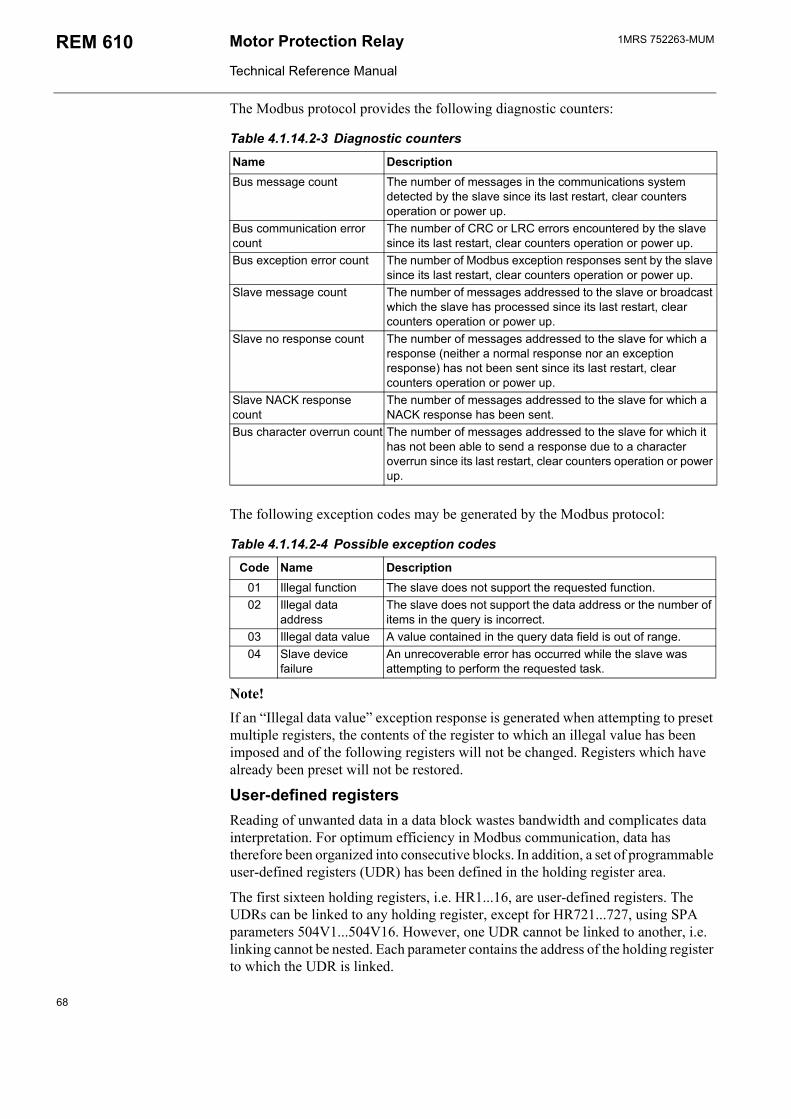
1MRS 752263-MUMMotor Protection Relay
Technical Reference Manual
REM 610
The Modbus protocol provides the following diagnostic counters:
Table 4.1.14.2-3 Diagnostic counters
Name DescriptionBus message count The number of messages in the communications system
detected by the slave since its last restart, clear counters operation or power up.
Bus communication error count
The number of CRC or LRC errors encountered by the slave since its last restart, clear counters operation or power up.
Bus exception error count The number of Modbus exception responses sent by the slave since its last restart, clear counters operation or power up.
Slave message count The number of messages addressed to the slave or broadcast which the slave has processed since its last restart, clear counters operation or power up.
Slave no response count The number of messages addressed to the slave for which a response (neither a normal response nor an exception response) has not been sent since its last restart, clear counters operation or power up.
Slave NACK response count
The number of messages addressed to the slave for which a NACK response has been sent.
Bus character overrun count The number of messages addressed to the slave for which it has not been able to send a response due to a character overrun since its last restart, clear counters operation or power up.
The following exception codes may be generated by the Modbus protocol:
Table 4.1.14.2-4 Possible exception codes
Code Name Description01 Illegal function The slave does not support the requested function.02 Illegal data
addressThe slave does not support the data address or the number of items in the query is incorrect.
03 Illegal data value A value contained in the query data field is out of range.04 Slave device
failureAn unrecoverable error has occurred while the slave was attempting to perform the requested task.
Note!If an Illegal data value exception response is generated when attempting to preset multiple registers, the contents of the register to which an illegal value has been imposed and of the following registers will not be changed. Registers which have already been preset will not be restored.
User-defined registersReading of unwanted data in a data block wastes bandwidth and complicates data interpretation. For optimum efficiency in Modbus communication, data has therefore been organized into consecutive blocks. In addition, a set of programmable user-defined registers (UDR) has been defined in the holding register area.
The first sixteen holding registers, i.e. HR1...16, are user-defined registers. The UDRs can be linked to any holding register, except for HR721...727, using SPA parameters 504V1...504V16. However, one UDR cannot be linked to another, i.e. linking cannot be nested. Each parameter contains the address of the holding register to which the UDR is linked.
68
1MRS 752263-MUM Motor protection Relay
Technical Reference Manual
REM 610
If a UDR is linked to a non-existent holding register, reading from the register will fail and an Illegal address exception response will be sent. Giving the link address the value 0 will disable the UDR. If the master reads from a disabled UDR, the value 0 will be returned.
The UDRs are mirrored in HR385400.
Fault recordsThe data recorded during a fault sequence is called a fault record (FR). The slave stores the five latest fault records. When a sixth record is stored, the oldest record will be deleted. To read a fault record:
1. Write a preset single register command (function 06) to HR601 using a selection code as data value.
2. Read the selected fault record (function 04) from HR601, register count 33.
Alternatively, a fault record can be read using one command (function 17H) only.
Selection code 1: The master reads the oldest unread recordStatus register 3 (HR403) informs whether there are unread fault records (see Fig. 4.1.14.2.-2). If there is one or several unread fault records, the master can read the contents using selection code 1.
The fault record contains a sequence number which makes it possible for the master to determine whether one or several unread fault records have been deleted due to overflow by comparing it to the sequence number of the previously read fault record.
The slave keeps track of which fault record is currently the oldest unread. The master can continue reading fault records for as long as Status register 3 indicates that there are unread records.
Special case 1: If there are no unread fault records, the contents of the last read record will be returned. If the buffer is empty, however, the registers will contain only zeros. This is the only time when sequence number zero will appear.
Special case 2: If the master tries to read the next unread fault record without entering selection code 1 again, the contents of the last read record will be returned.
Selection code 2: The master reads the oldest stored recordBy resetting the read pointer using selection code 2, the master can read the oldest stored fault record. After this, the master can continue reading the following records using selection code 1, irrespective of whether they have been read before.
Note!
Resetting the read pointer will not affect the sequence number of the fault record.
Note!
A master reset, i.e. clearing of indications and memorized values and unlatching of output contacts, will clear the fault records, after which the sequence number will start from 1 again.
Event recordsModbus events are derived from SPA events. With a few exceptions, SPA events update binary points in the DI and the packed HR area. Simultaneously, a corresponding Modbus event record will be generated. The event record contains the
69
1MRS 752263-MUMMotor Protection Relay
Technical Reference Manual
REM 610
Modbus DI/CO data point address and the value to which the point has changed (0 or 1). SPA events lacking a corresponding DI/CO data point are shown as SPA channel and event code (informative event) in the event record. The maximum capacity of the Modbus event buffer is 99 events. The time stamp of Modbus events is extended to contain complete information, from date to millisecond. To read an event record:
1. Write a preset single register command (function 06) to HR671 using a selection code as data value.
2. Read the selected event record (function 04) from HR672, register count 8.
Alternatively, an event record can be read using one command (function 23) only.
Selection code 1: reading the oldest unread recordStatus register 3 (HR403) informs whether there are unread event records (see Fig. 4.1.14.2.-2). If there is one or several unread event records, the master can read the contents using selection code 1.
The event record contains a sequence number which makes it possible for the master to determine whether one or several unread event records have been deleted due to overflow by comparing it to the sequence number of the previously read event record.
The slave keeps track of which event record is currently the oldest unread. The master can continue reading event records for as long as Status register 3 indicates that there are unread records.
Special case 1: If there are no unread event records, the contents of the last read record will be returned. If the buffer is empty, however, the registers will contain only zeros. This is the only time when sequence number zero will appear.
Special case 2: If the master tries to read the next unread event record without entering selection code 1 again, the contents of the last read record will be returned.
Selection code 2: reading the oldest stored recordBy resetting the read pointer using selection code 2, the master can read the oldest stored event record. After this, the master can continue reading the following records using selection code 1, irrespective of whether they have been read before.
Note!
Resetting the read pointer will not affect the sequence number of the event record.
Selection code -1...-99With selection code -1...-99, the master can move backwards from the newest event as many events as defined by the selection code and read that specific event record. After this, the master can continue reading the following records using selection code 1, irrespective of whether they have been read before.
Special case: If there is not as many events in the buffer as specified by the selection code, the oldest stored event will be read.
Selection code 3The Modbus event buffer is cleared with selection code 3. Clearing the buffer does not require any read operation to follow.
70
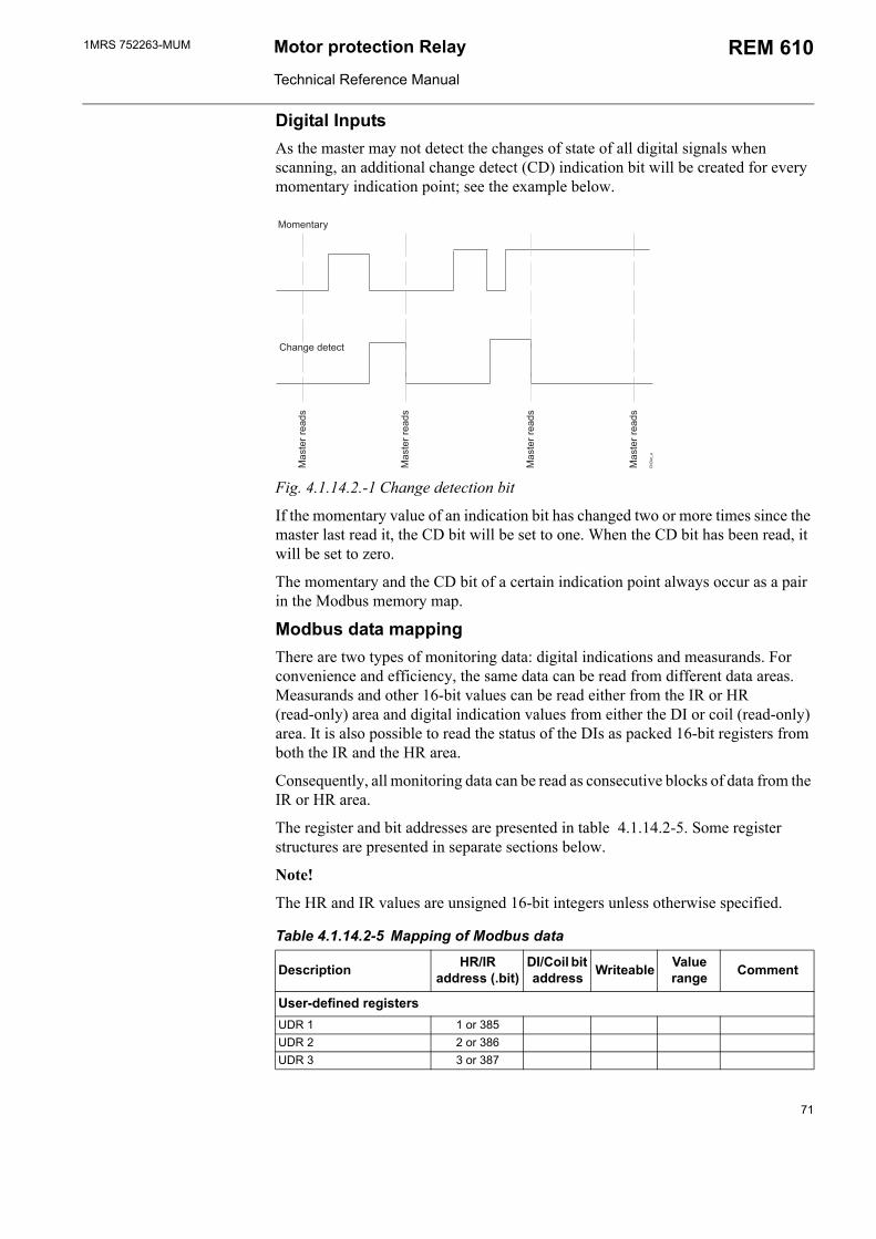
1MRS 752263-MUM Motor protection Relay
Technical Reference Manual
REM 610
Digital InputsAs the master may not detect the changes of state of all digital signals when scanning, an additional change detect (CD) indication bit will be created for every momentary indication point; see the example below.
<
2"=
2
2
2
2
0)
Fig. 4.1.14.2.-1 Change detection bit
If the momentary value of an indication bit has changed two or more times since the master last read it, the CD bit will be set to one. When the CD bit has been read, it will be set to zero.
The momentary and the CD bit of a certain indication point always occur as a pair in the Modbus memory map.
Modbus data mappingThere are two types of monitoring data: digital indications and measurands. For convenience and efficiency, the same data can be read from different data areas. Measurands and other 16-bit values can be read either from the IR or HR (read-only) area and digital indication values from either the DI or coil (read-only) area. It is also possible to read the status of the DIs as packed 16-bit registers from both the IR and the HR area.
Consequently, all monitoring data can be read as consecutive blocks of data from the IR or HR area.
The register and bit addresses are presented in table 4.1.14.2-5. Some register structures are presented in separate sections below.
Note!
The HR and IR values are unsigned 16-bit integers unless otherwise specified.
Table 4.1.14.2-5 Mapping of Modbus data
Description HR/IR address (.bit)
DI/Coil bit address Writeable Value
range Comment
User-defined registersUDR 1 1 or 385UDR 2 2 or 386UDR 3 3 or 387
71
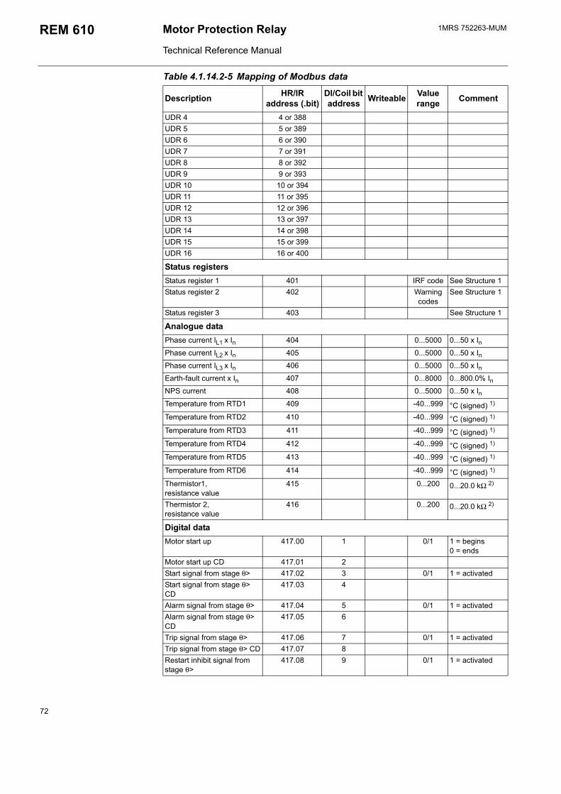
1MRS 752263-MUMMotor Protection Relay
Technical Reference Manual
REM 610
UDR 4 4 or 388UDR 5 5 or 389UDR 6 6 or 390UDR 7 7 or 391UDR 8 8 or 392UDR 9 9 or 393UDR 10 10 or 394UDR 11 11 or 395UDR 12 12 or 396UDR 13 13 or 397UDR 14 14 or 398UDR 15 15 or 399UDR 16 16 or 400
Status registersStatus register 1 401 IRF code See Structure 1Status register 2 402 Warning
codesSee Structure 1
Status register 3 403 See Structure 1
Analogue dataPhase current IL1 x In 404 0...5000 0...50 x InPhase current IL2 x In 405 0...5000 0...50 x InPhase current IL3 x In 406 0...5000 0...50 x InEarth-fault current x In 407 0...8000 0...800.0% InNPS current 408 0...5000 0...50 x InTemperature from RTD1 409 -40...999 °C (signed) 1)
Temperature from RTD2 410 -40...999 °C (signed) 1)
Temperature from RTD3 411 -40...999 °C (signed) 1)
Temperature from RTD4 412 -40...999 °C (signed) 1)
Temperature from RTD5 413 -40...999 °C (signed) 1)
Temperature from RTD6 414 -40...999 °C (signed) 1)
Thermistor1, resistance value
415 0...200 0...20.0 kΩ 2)
Thermistor 2, resistance value
416 0...200 0...20.0 kΩ 2)
Digital dataMotor start up 417.00 1 0/1 1 = begins
0 = endsMotor start up CD 417.01 2Start signal from stage θ> 417.02 3 0/1 1 = activatedStart signal from stage θ> CD
417.03 4
Alarm signal from stage θ> 417.04 5 0/1 1 = activatedAlarm signal from stage θ> CD
417.05 6
Trip signal from stage θ> 417.06 7 0/1 1 = activatedTrip signal from stage θ> CD 417.07 8Restart inhibit signal from stage θ>
417.08 9 0/1 1 = activated
Table 4.1.14.2-5 Mapping of Modbus data
Description HR/IR address (.bit)
DI/Coil bit address Writeable Value
range Comment
72
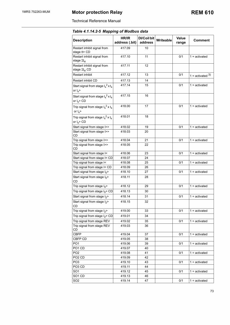
1MRS 752263-MUM Motor protection Relay
Technical Reference Manual
REM 610
Restart inhibit signal from stage θ> CD
417.09 10
Restart inhibit signal from stage Σtsi
417.10 11 0/1 1 = activated
Restart inhibit signal from stage Σtsi CD
417.11 12
Restart inhibit 417.12 13 0/1 1 = activated 3)
Restart inhibit CD 417.13 14
Start signal from stage Is2 x ts or Is>
417.14 15 0/1 1 = activated
Start signal from stage Is2 x ts or Is> CD
417.15 16
Trip signal from stage Is2 x ts or Is>
418.00 17 0/1 1 = activated
Trip signal from stage Is2 x ts or Is> CD
418.01 18
Start signal from stage I>> 418.02 19 0/1 1 = activatedStart signal from stage I>> CD
418.03 20
Trip signal from stage I>> 418.04 21 0/1 1 = activatedTrip signal from stage I>> CD
418.05 22
Start signal from stage I< 418.06 23 0/1 1 = activatedStart signal from stage I< CD 418.07 24Trip signal from stage I< 418.08 25 0/1 1 = activatedTrip signal from stage I< CD 418.09 26Start signal from stage I0> 418.10 27 0/1 1 = activated
Start signal from stage I0> CD
418.11 28
Trip signal from stage I0> 418.12 29 0/1 1 = activated
Trip signal from stage I0> CD 418.13 30
Start signal from stage I2> 418.14 31 0/1 1 = activated
Start signal from stage I2> CD
418.15 32
Trip signal from stage I2> 419.00 33 0/1 1 = activated
Trip signal from stage I2> CD 419.01 34
Trip signal from stage REV 419.02 35 0/1 1 = activatedTrip signal from stage REV CD
419.03 36
CBFP 419.04 37 0/1 1 = activatedCBFP CD 419.05 38PO1 419.06 39 0/1 1 = activatedPO1 CD 419.07 40PO2 419.08 41 0/1 1 = activatedPO2 CD 419.09 42PO3 419.10 43 0/1 1 = activatedPO3 CD 419.11 44SO1 419.12 45 0/1 1 = activatedSO1 CD 419.13 46SO2 419.14 47 0/1 1 = activated
Table 4.1.14.2-5 Mapping of Modbus data
Description HR/IR address (.bit)
DI/Coil bit address Writeable Value
range Comment
73
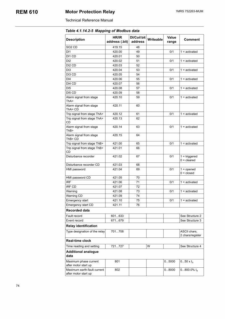
1MRS 752263-MUMMotor Protection Relay
Technical Reference Manual
REM 610
SO2 CD 419.15 48DI1 420.00 49 0/1 1 = activatedDI1 CD 420.01 50DI2 420.02 51 0/1 1 = activatedDI2 CD 420.03 52DI3 420.04 53 0/1 1 = activatedDI3 CD 420.05 54DI4 420.06 55 0/1 1 = activatedDI4 CD 420.07 56DI5 420.08 57 0/1 1 = activatedDI5 CD 420.09 58Alarm signal from stage ThA>
420.10 59 0/1 1 = activated
Alarm signal from stage ThA> CD
420.11 60
Trip signal from stage ThA> 420.12 61 0/1 1 = activatedTrip signal from stage ThA> CD
420.13 62
Alarm signal from stage ThB>
420.14 63 0/1 1 = activated
Alarm signal from stage ThB> CD
420.15 64
Trip signal from stage ThB> 421.00 65 0/1 1 = activatedTrip signal from stage ThB> CD
421.01 66
Disturbance recorder 421.02 67 0/1 1 = triggered 0 = cleared
Disturbance recorder CD 421.03 68HMI password 421.04 69 0/1 1 = opened
0 = closedHMI password CD 421.05 70IRF 421.06 71 0/1 1 = activatedIRF CD 421.07 72Warning 421.08 73 0/1 1 = activatedWarning CD 421.09 74Emergency start 421.10 75 0/1 1 = activatedEmergency start CD 421.11 76
Recorded dataFault record 601...633 See Structure 2Event record 671...679 See Structure 3
Relay identificationType designation of the relay 701...708 ASCII chars,
2 chars/register
Real-time clockTime reading and setting 721...727 W See Structure 4
Additional analogue dataMaximum phase current after motor start up
801 0...5000 0...50 x In
Maximum earth-fault current after motor start up
802 0...8000 0...800.0% In
Table 4.1.14.2-5 Mapping of Modbus data
Description HR/IR address (.bit)
DI/Coil bit address Writeable Value
range Comment
74
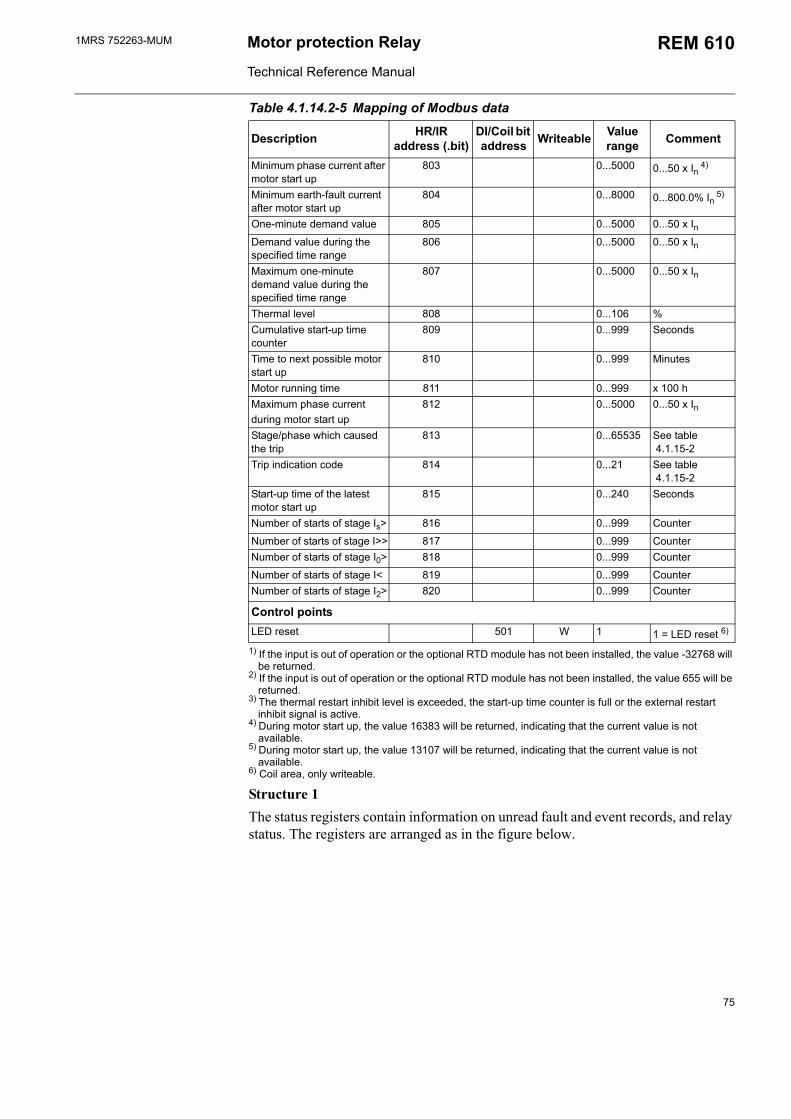
1MRS 752263-MUM Motor protection Relay
Technical Reference Manual
REM 610
1) If the input is out of operation or the optional RTD module has not been installed, the value -32768 will be returned.
2) If the input is out of operation or the optional RTD module has not been installed, the value 655 will be returned.
3) The thermal restart inhibit level is exceeded, the start-up time counter is full or the external restart inhibit signal is active.
4) During motor start up, the value 16383 will be returned, indicating that the current value is not available.
5) During motor start up, the value 13107 will be returned, indicating that the current value is not available.
6) Coil area, only writeable.
Structure 1The status registers contain information on unread fault and event records, and relay status. The registers are arranged as in the figure below.
Minimum phase current after motor start up
803 0...5000 0...50 x In 4)
Minimum earth-fault current after motor start up
804 0...8000 0...800.0% In 5)
One-minute demand value 805 0...5000 0...50 x InDemand value during the specified time range
806 0...5000 0...50 x In
Maximum one-minute demand value during the specified time range
807 0...5000 0...50 x In
Thermal level 808 0...106 %Cumulative start-up time counter
809 0...999 Seconds
Time to next possible motor start up
810 0...999 Minutes
Motor running time 811 0...999 x 100 hMaximum phase current during motor start up
812 0...5000 0...50 x In
Stage/phase which caused the trip
813 0...65535 See table 4.1.15-2
Trip indication code 814 0...21 See table 4.1.15-2
Start-up time of the latest motor start up
815 0...240 Seconds
Number of starts of stage Is> 816 0...999 Counter
Number of starts of stage I>> 817 0...999 CounterNumber of starts of stage I0> 818 0...999 Counter
Number of starts of stage I< 819 0...999 CounterNumber of starts of stage I2> 820 0...999 Counter
Control pointsLED reset 501 W 1 1 = LED reset 6)
Table 4.1.14.2-5 Mapping of Modbus data
Description HR/IR address (.bit)
DI/Coil bit address Writeable Value
range Comment
75
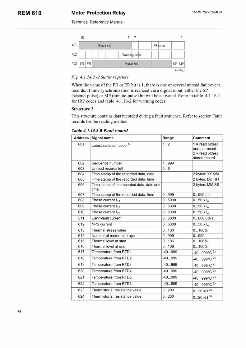
1MRS 752263-MUMMotor Protection Relay
Technical Reference Manual
REM 610
/
#!(0'
(
5&0)
(>)
(>( 1( #, 2,
Fig. 4.1.14.2.-2 Status registers
When the value of the FR or ER bit is 1, there is one or several unread fault/event records. If time synchronization is realized via a digital input, either the SP (second-pulse) or MP (minute-pulse) bit will be activated. Refer to table 4.1.16-1 for IRF codes and table 4.1.16-2 for warning codes.
Structure 2This structure contains data recorded during a fault sequence. Refer to section Fault records for the reading method.
Table 4.1.14.2-6 Fault record
Address Signal name Range Comment601 Latest selection code 1) 1...2 1 = read oldest
unread record2 = read oldest stored record
602 Sequence number 1...999603 Unread records left 0...6604 Time stamp of the recorded data, date 2 bytes: YY.MM605 Time stamp of the recorded data, time 2 bytes: DD.HH606 Time stamp of the recorded data, date and
time2 bytes: MM.SS
607 Time stamp of the recorded data, time 0...999 0...999 ms608 Phase current IL1 0...5000 0...50 x In609 Phase current IL2 0...5000 0...50 x In610 Phase current IL3 0...5000 0...50 x In611 Earth-fault current 0...8000 0...800.0% In612 NPS current 0...5000 0...50 x In613 Thermal stress value 0...100 0...100%614 Number of motor start ups 0...999 0...999615 Thermal level at start 0...106 0...106%616 Thermal level at end 0...106 0...106%617 Temperature from RTD1 -40...999 -40...999°C 2)
618 Temperature from RTD2 -40...999 -40...999°C 2)
619 Temperature from RTD3 -40...999 -40...999°C 2)
620 Temperature from RTD4 -40...999 -40...999°C 2)
621 Temperature from RTD5 -40...999 -40...999°C 2)
622 Temperature from RTD6 -40...999 -40...999°C 2)
623 Thermistor 1, resistance value 0...200 0...20 kΩ 3)
624 Thermistor 2, resistance value 0...200 0...20 kΩ 3)
76
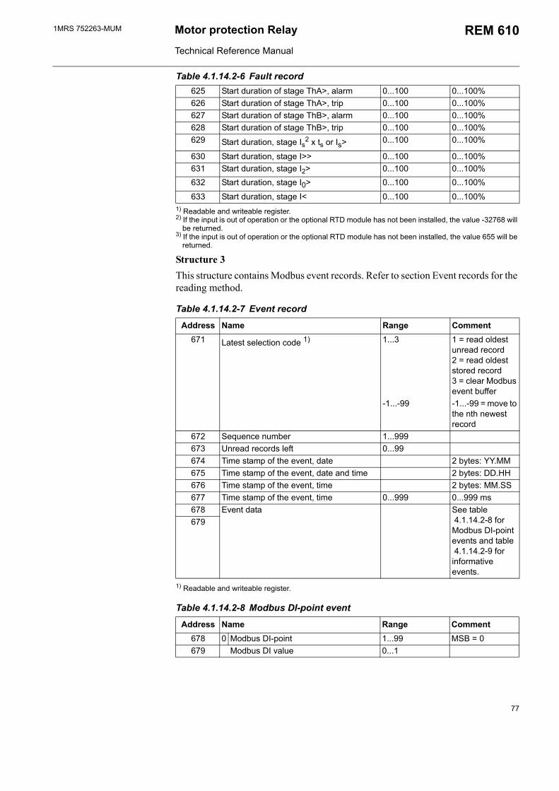
1MRS 752263-MUM Motor protection Relay
Technical Reference Manual
REM 610
1) Readable and writeable register.2) If the input is out of operation or the optional RTD module has not been installed, the value -32768 will
be returned.3) If the input is out of operation or the optional RTD module has not been installed, the value 655 will be
returned.
Structure 3This structure contains Modbus event records. Refer to section Event records for the reading method.
Table 4.1.14.2-7 Event record
Address Name Range Comment671 Latest selection code 1) 1...3 1 = read oldest
unread record2 = read oldest stored record3 = clear Modbus event buffer
-1...-99 -1...-99 = move to the nth newest record
672 Sequence number 1...999673 Unread records left 0...99674 Time stamp of the event, date 2 bytes: YY.MM675 Time stamp of the event, date and time 2 bytes: DD.HH676 Time stamp of the event, time 2 bytes: MM.SS677 Time stamp of the event, time 0...999 0...999 ms678 Event data See table
4.1.14.2-8 for Modbus DI-point events and table 4.1.14.2-9 for informative events.
679
1) Readable and writeable register.
Table 4.1.14.2-8 Modbus DI-point event
Address Name Range Comment678 0 Modbus DI-point 1...99 MSB = 0679 Modbus DI value 0...1
625 Start duration of stage ThA>, alarm 0...100 0...100%626 Start duration of stage ThA>, trip 0...100 0...100%627 Start duration of stage ThB>, alarm 0...100 0...100%628 Start duration of stage ThB>, trip 0...100 0...100%629 Start duration, stage Is2 x ts or Is> 0...100 0...100%
630 Start duration, stage I>> 0...100 0...100%631 Start duration, stage I2> 0...100 0...100%632 Start duration, stage I0> 0...100 0...100%
633 Start duration, stage I< 0...100 0...100%
Table 4.1.14.2-6 Fault record
77
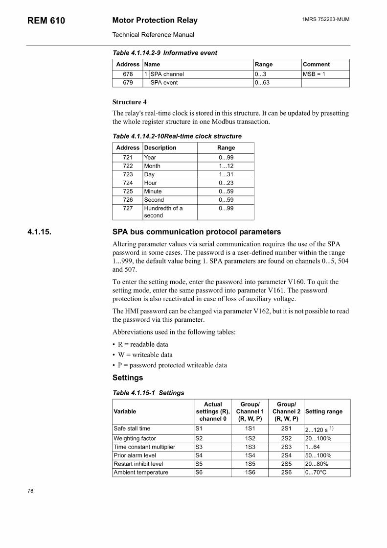
1MRS 752263-MUMMotor Protection Relay
Technical Reference Manual
REM 610
Table 4.1.14.2-9 Informative event
Address Name Range Comment678 1 SPA channel 0...3 MSB = 1679 SPA event 0...63
Structure 4The relay's real-time clock is stored in this structure. It can be updated by presetting the whole register structure in one Modbus transaction.
Table 4.1.14.2-10Real-time clock structure
Address Description Range721 Year 0...99722 Month 1...12723 Day 1...31724 Hour 0...23725 Minute 0...59726 Second 0...59727 Hundredth of a
second0...99
4.1.15. SPA bus communication protocol parametersAltering parameter values via serial communication requires the use of the SPA password in some cases. The password is a user-defined number within the range 1...999, the default value being 1. SPA parameters are found on channels 0...5, 504 and 507.
To enter the setting mode, enter the password into parameter V160. To quit the setting mode, enter the same password into parameter V161. The password protection is also reactivated in case of loss of auxiliary voltage.
The HMI password can be changed via parameter V162, but it is not possible to read the password via this parameter.
Abbreviations used in the following tables:
R = readable data W = writeable data P = password protected writeable data
Settings
Table 4.1.15-1 Settings
VariableActual
settings (R),channel 0
Group/Channel 1 (R, W, P)
Group/Channel 2 (R, W, P)
Setting range
Safe stall time S1 1S1 2S1 2...120 s 1)
Weighting factor S2 1S2 2S2 20...100%Time constant multiplier S3 1S3 2S3 1...64Prior alarm level S4 1S4 2S4 50...100%Restart inhibit level S5 1S5 2S5 20...80%Ambient temperature S6 1S6 2S6 0...70°C
78
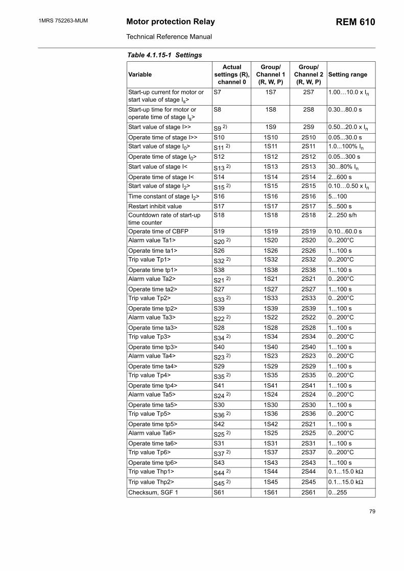
1MRS 752263-MUM Motor protection Relay
Technical Reference Manual
REM 610
Start-up current for motor or start value of stage Is>
S7 1S7 2S7 1.0010.0 x In
Start-up time for motor or operate time of stage Is>
S8 1S8 2S8 0.30...80.0 s
Start value of stage I>> S9 2) 1S9 2S9 0.50...20.0 x InOperate time of stage I>> S10 1S10 2S10 0.05...30.0 sStart value of stage I0> S11 2) 1S11 2S11 1.0...100% InOperate time of stage I0> S12 1S12 2S12 0.05...300 sStart value of stage I< S13 2) 1S13 2S13 30...80% InOperate time of stage I< S14 1S14 2S14 2...600 sStart value of stage I2> S15 2) 1S15 2S15 0.100.50 x InTime constant of stage I2> S16 1S16 2S16 5...100Restart inhibit value S17 1S17 2S17 5...500 sCountdown rate of start-up time counter
S18 1S18 2S18 2...250 s/h
Operate time of CBFP S19 1S19 2S19 0.10...60.0 sAlarm value Ta1> S20 2) 1S20 2S20 0...200°C
Operate time ta1> S26 1S26 2S26 1...100 sTrip value Tp1> S32 2) 1S32 2S32 0...200°C
Operate time tp1> S38 1S38 2S38 1...100 sAlarm value Ta2> S21 2) 1S21 2S21 0...200°C
Operate time ta2> S27 1S27 2S27 1...100 sTrip value Tp2> S33 2) 1S33 2S33 0...200°C
Operate time tp2> S39 1S39 2S39 1...100 sAlarm value Ta3> S22 2) 1S22 2S22 0...200°C
Operate time ta3> S28 1S28 2S28 1...100 sTrip value Tp3> S34 2) 1S34 2S34 0...200°C
Operate time tp3> S40 1S40 2S40 1...100 sAlarm value Ta4> S23 2) 1S23 2S23 0...200°C
Operate time ta4> S29 1S29 2S29 1...100 sTrip value Tp4> S35 2) 1S35 2S35 0...200°C
Operate time tp4> S41 1S41 2S41 1...100 sAlarm value Ta5> S24 2) 1S24 2S24 0...200°C
Operate time ta5> S30 1S30 2S30 1...100 sTrip value Tp5> S36 2) 1S36 2S36 0...200°C
Operate time tp5> S42 1S42 2S21 1...100 sAlarm value Ta6> S25 2) 1S25 2S25 0...200°C
Operate time ta6> S31 1S31 2S31 1...100 sTrip value Tp6> S37 2) 1S37 2S37 0...200°C
Operate time tp6> S43 1S43 2S43 1...100 sTrip value Thp1> S44 2) 1S44 2S44 0.1...15.0 kΩ
Trip value Thp2> S45 2) 1S45 2S45 0.1...15.0 kΩ
Checksum, SGF 1 S61 1S61 2S61 0...255
Table 4.1.15-1 Settings
VariableActual
settings (R),channel 0
Group/Channel 1 (R, W, P)
Group/Channel 2 (R, W, P)
Setting range
79
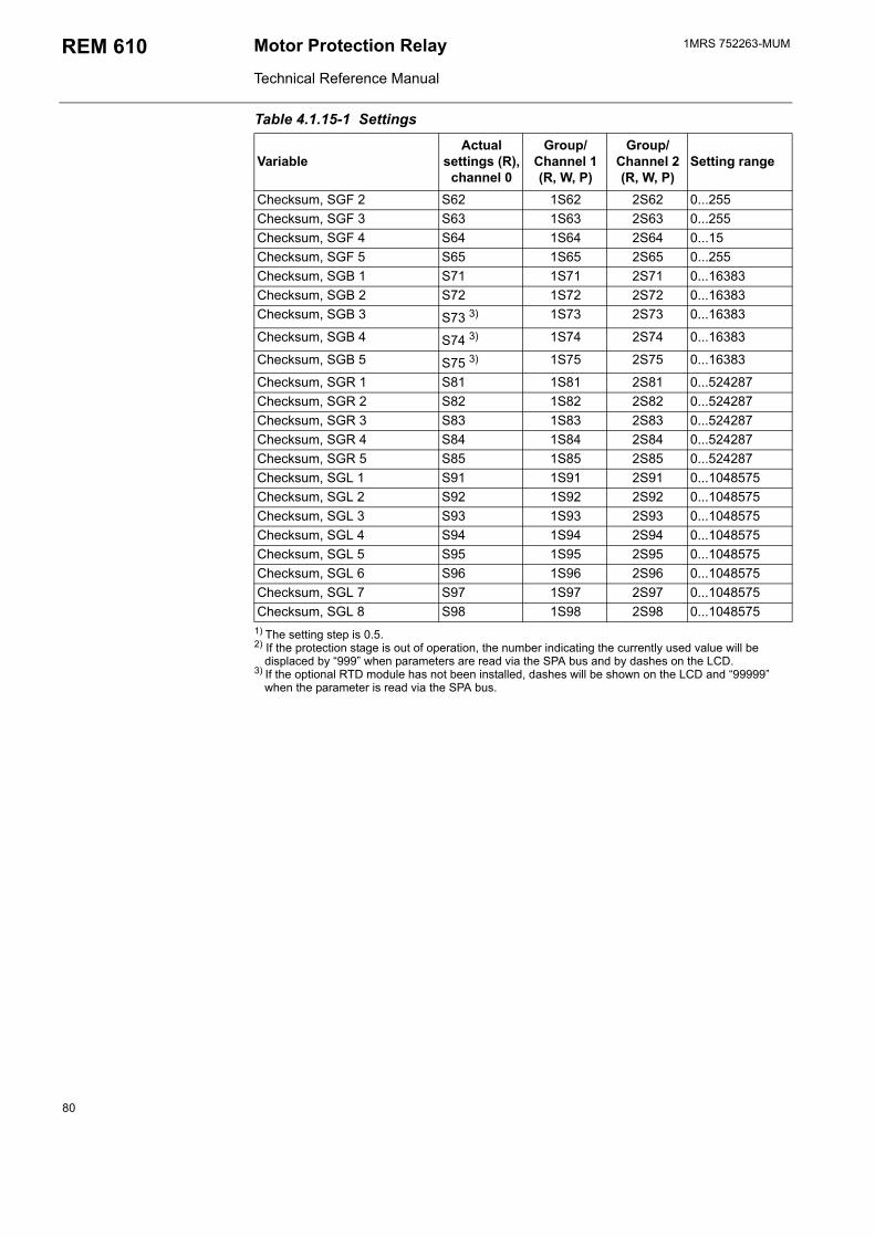
1MRS 752263-MUMMotor Protection Relay
Technical Reference Manual
REM 610
1) The setting step is 0.5.2) If the protection stage is out of operation, the number indicating the currently used value will be
displaced by 999 when parameters are read via the SPA bus and by dashes on the LCD.3) If the optional RTD module has not been installed, dashes will be shown on the LCD and 99999
when the parameter is read via the SPA bus.
Checksum, SGF 2 S62 1S62 2S62 0...255Checksum, SGF 3 S63 1S63 2S63 0...255Checksum, SGF 4 S64 1S64 2S64 0...15Checksum, SGF 5 S65 1S65 2S65 0...255Checksum, SGB 1 S71 1S71 2S71 0...16383Checksum, SGB 2 S72 1S72 2S72 0...16383Checksum, SGB 3 S73 3) 1S73 2S73 0...16383
Checksum, SGB 4 S74 3) 1S74 2S74 0...16383
Checksum, SGB 5 S75 3) 1S75 2S75 0...16383
Checksum, SGR 1 S81 1S81 2S81 0...524287Checksum, SGR 2 S82 1S82 2S82 0...524287Checksum, SGR 3 S83 1S83 2S83 0...524287Checksum, SGR 4 S84 1S84 2S84 0...524287Checksum, SGR 5 S85 1S85 2S85 0...524287Checksum, SGL 1 S91 1S91 2S91 0...1048575Checksum, SGL 2 S92 1S92 2S92 0...1048575Checksum, SGL 3 S93 1S93 2S93 0...1048575Checksum, SGL 4 S94 1S94 2S94 0...1048575Checksum, SGL 5 S95 1S95 2S95 0...1048575Checksum, SGL 6 S96 1S96 2S96 0...1048575Checksum, SGL 7 S97 1S97 2S97 0...1048575Checksum, SGL 8 S98 1S98 2S98 0...1048575
Table 4.1.15-1 Settings
VariableActual
settings (R),channel 0
Group/Channel 1 (R, W, P)
Group/Channel 2 (R, W, P)
Setting range
80
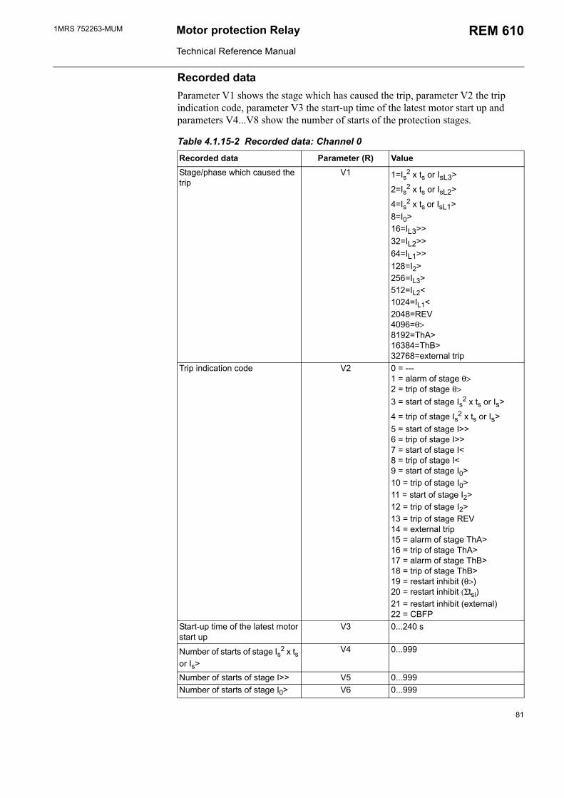
1MRS 752263-MUM Motor protection Relay
Technical Reference Manual
REM 610
Recorded dataParameter V1 shows the stage which has caused the trip, parameter V2 the trip indication code, parameter V3 the start-up time of the latest motor start up and parameters V4...V8 show the number of starts of the protection stages.
Table 4.1.15-2 Recorded data: Channel 0
Recorded data Parameter (R) ValueStage/phase which caused the trip
V1 1=Is2 x ts or IsL3>
2=Is2 x ts or IsL2>
4=Is2 x ts or IsL1>8=I0>16=IL3>> 32=IL2>>64=IL1>>128=I2>256=IL3>512=IL2<1024=IL1<2048=REV4096=θ>8192=ThA>16384=ThB>32768=external trip
Trip indication code V2 0 = ---1 = alarm of stage θ>2 = trip of stage θ>3 = start of stage Is2 x ts or Is>
4 = trip of stage Is2 x ts or Is>5 = start of stage I>>6 = trip of stage I>>7 = start of stage I<8 = trip of stage I<9 = start of stage I0>10 = trip of stage I0>11 = start of stage I2>12 = trip of stage I2>13 = trip of stage REV14 = external trip15 = alarm of stage ThA>16 = trip of stage ThA>17 = alarm of stage ThB>18 = trip of stage ThB>19 = restart inhibit (θ>)20 = restart inhibit (Σtsi)21 = restart inhibit (external)22 = CBFP
Start-up time of the latest motor start up
V3 0...240 s
Number of starts of stage Is2 x ts or Is>
V4 0...999
Number of starts of stage I>> V5 0...999Number of starts of stage I0> V6 0...999
81
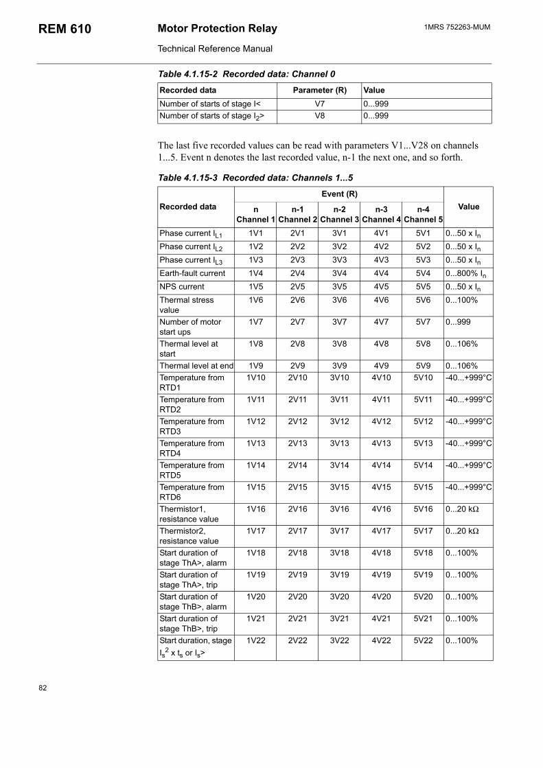
1MRS 752263-MUMMotor Protection Relay
Technical Reference Manual
REM 610
The last five recorded values can be read with parameters V1...V28 on channels 1...5. Event n denotes the last recorded value, n-1 the next one, and so forth.
Number of starts of stage I< V7 0...999Number of starts of stage I2> V8 0...999
Table 4.1.15-3 Recorded data: Channels 1...5
Recorded dataEvent (R)
ValuenChannel 1
n-1Channel 2
n-2Channel 3
n-3Channel 4
n-4Channel 5
Phase current IL1 1V1 2V1 3V1 4V1 5V1 0...50 x InPhase current IL2 1V2 2V2 3V2 4V2 5V2 0...50 x InPhase current IL3 1V3 2V3 3V3 4V3 5V3 0...50 x InEarth-fault current 1V4 2V4 3V4 4V4 5V4 0...800% InNPS current 1V5 2V5 3V5 4V5 5V5 0...50 x InThermal stress value
1V6 2V6 3V6 4V6 5V6 0...100%
Number of motor start ups
1V7 2V7 3V7 4V7 5V7 0...999
Thermal level at start
1V8 2V8 3V8 4V8 5V8 0...106%
Thermal level at end 1V9 2V9 3V9 4V9 5V9 0...106%Temperature from RTD1
1V10 2V10 3V10 4V10 5V10 -40...+999°C
Temperature from RTD2
1V11 2V11 3V11 4V11 5V11 -40...+999°C
Temperature from RTD3
1V12 2V12 3V12 4V12 5V12 -40...+999°C
Temperature from RTD4
1V13 2V13 3V13 4V13 5V13 -40...+999°C
Temperature from RTD5
1V14 2V14 3V14 4V14 5V14 -40...+999°C
Temperature from RTD6
1V15 2V15 3V15 4V15 5V15 -40...+999°C
Thermistor1, resistance value
1V16 2V16 3V16 4V16 5V16 0...20 kΩ
Thermistor2, resistance value
1V17 2V17 3V17 4V17 5V17 0...20 kΩ
Start duration of stage ThA>, alarm
1V18 2V18 3V18 4V18 5V18 0...100%
Start duration of stage ThA>, trip
1V19 2V19 3V19 4V19 5V19 0...100%
Start duration of stage ThB>, alarm
1V20 2V20 3V20 4V20 5V20 0...100%
Start duration of stage ThB>, trip
1V21 2V21 3V21 4V21 5V21 0...100%
Start duration, stage Is2 x ts or Is>
1V22 2V22 3V22 4V22 5V22 0...100%
Table 4.1.15-2 Recorded data: Channel 0
Recorded data Parameter (R) Value
82
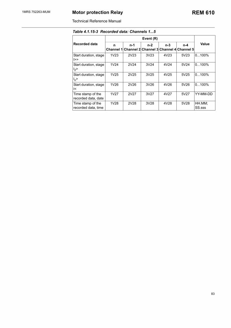
1MRS 752263-MUM Motor protection Relay
Technical Reference Manual
REM 610
Start duration, stage I>>
1V23 2V23 3V23 4V23 5V23 0...100%
Start duration, stage I2>
1V24 2V24 3V24 4V24 5V24 0...100%
Start duration, stage Io>
1V25 2V25 3V25 4V25 5V25 0...100%
Start duration, stage I<
1V26 2V26 3V26 4V26 5V26 0...100%
Time stamp of the recorded data, date
1V27 2V27 3V27 4V27 5V27 YY-MM-DD
Time stamp of the recorded data, time
1V28 2V28 3V28 4V28 5V28 HH.MM; SS.sss
Table 4.1.15-3 Recorded data: Channels 1...5
Recorded dataEvent (R)
ValuenChannel 1
n-1Channel 2
n-2Channel 3
n-3Channel 4
n-4Channel 5
83
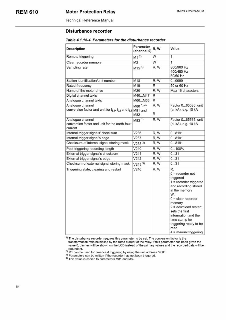
1MRS 752263-MUMMotor Protection Relay
Technical Reference Manual
REM 610
Disturbance recorder
Table 4.1.15-4 Parameters for the disturbance recorder
Description Parameter (channel 0) R, W Value
Remote triggering M1 2) W 1
Clear recorder memory M2 W 1Sampling rate M15 3) R, W 800/960 Hz
400/480 Hz50/60 Hz
Station identification/unit number M18 R, W 0...9999Rated frequency M19 R 50 or 60 HzName of the motor drive M20 R, W Max 16 charactersDigital channel texts M40...M47 RAnalogue channel texts M60...M63 RAnalogue channel conversion factor and unit for IL1, IL2 and IL3
M80 1) 4) M81 and M82
R, W R
Factor 0...65535, unit (a, kA), e.g. 10 kA
Analogue channel conversion factor and unit for the earth-fault current
M83 1) R, W Factor 0...65535, unit (a, kA), e.g. 10 kA
Internal trigger signals' checksum V236 R, W 0...8191Internal trigger signal's edge V237 R, W 0...8191Checksum of internal signal storing mask V238 3) R, W 0...8191
Post-triggering recording length V240 R, W 0...100%External trigger signal's checksum V241 R, W 0...31External trigger signal's edge V242 R, W 0...31Checksum of external signal storing mask V243 3) R, W 0...31
Triggering state, clearing and restart V246 R, W R:0 = recorder not triggered1 = recorder triggered and recording stored in the memoryW:0 = clear recorder memory2 = download restart; sets the first information and the time stamp for triggering ready to be read4 = manual triggering
1) The disturbance recorder requires this parameter to be set. The conversion factor is the transformation ratio multiplied by the rated current of the relay. If this parameter has been given the value 0, dashes will be shown on the LCD instead of the primary values and the recorded data will be redundant.
2) M1 can be used for broadcast triggering by using the unit address 900.3) Parameters can be written if the recorder has not been triggered.4) This value is copied to parameters M81 and M82.
84
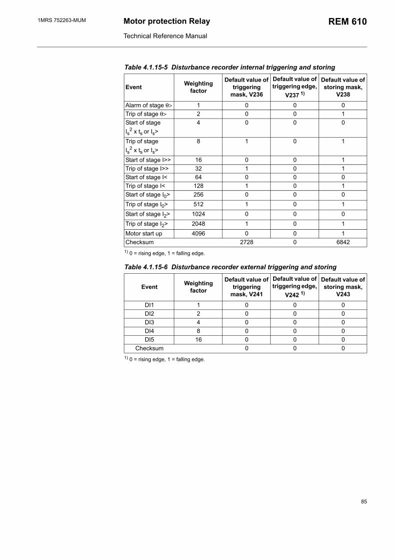
1MRS 752263-MUM Motor protection Relay
Technical Reference Manual
REM 610
Table 4.1.15-5 Disturbance recorder internal triggering and storing
Event Weighting factor
Default value of triggering
mask, V236
Default value of triggering edge,
V237 1)
Default value of storing mask,
V238
Alarm of stage θ> 1 0 0 0Trip of stage θ> 2 0 0 1Start of stage Is2 x ts or Is>
4 0 0 0
Trip of stage Is2 x ts or Is>
8 1 0 1
Start of stage I>> 16 0 0 1Trip of stage I>> 32 1 0 1Start of stage I< 64 0 0 0Trip of stage I< 128 1 0 1Start of stage I0> 256 0 0 0Trip of stage I0> 512 1 0 1Start of stage I2> 1024 0 0 0Trip of stage I2> 2048 1 0 1Motor start up 4096 0 0 1Checksum 2728 0 6842
1) 0 = rising edge, 1 = falling edge.
Table 4.1.15-6 Disturbance recorder external triggering and storing
Event Weighting factor
Default value of triggering
mask, V241
Default value of triggering edge,
V242 1)
Default value of storing mask,
V243
DI1 1 0 0 0DI2 2 0 0 0DI3 4 0 0 0DI4 8 0 0 0DI5 16 0 0 0
Checksum 0 0 0
1) 0 = rising edge, 1 = falling edge.
85
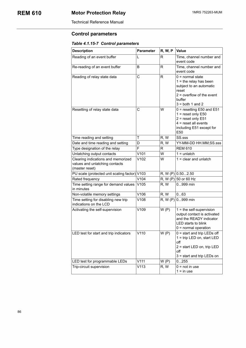
1MRS 752263-MUMMotor Protection Relay
Technical Reference Manual
REM 610
Control parameters
Table 4.1.15-7 Control parameters
Description Parameter R, W, P ValueReading of an event buffer L R Time, channel number and
event codeRe-reading of an event buffer B R Time, channel number and
event codeReading of relay state data C R 0 = normal state
1 = the relay has been subject to an automatic reset2 = overflow of the event buffer3 = both 1 and 2
Resetting of relay state data C W 0 = resetting E50 and E511 = reset only E502 = reset only E514 = reset all events including E51 except for E50
Time reading and setting T R, W SS.sssDate and time reading and setting D R, W YY-MM-DD HH.MM;SS.sssType designation of the relay F R REM 610Unlatching output contacts V101 W 1 = unlatchClearing indications and memorized values and unlatching contacts (master reset)
V102 W 1 = clear and unlatch
PU scale (protected unit scaling factor) V103 R, W (P) 0.50...2.50Rated frequency V104 R, W (P) 50 or 60 HzTime setting range for demand values in minutes
V105 R, W 0...999 min
Non-volatile memory settings V106 R, W 0...63Time setting for disabling new trip indications on the LCD
V108 R, W (P) 0...999 min
Activating the self-supervision V109 W (P) 1 = the self-supervision output contact is activated and the READY indicator LED starts to blink0 = normal operation
LED test for start and trip indicators V110 W (P) 0 = start and trip LEDs off1 = trip LED on, start LED off2 = start LED on, trip LED off3 = start and trip LEDs on
LED test for programmable LEDs V111 W (P) 0...255Trip-circuit supervision V113 R, W 0 = not in use
1 = in use
86
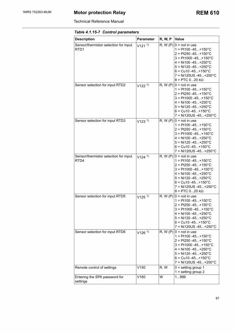
1MRS 752263-MUM Motor protection Relay
Technical Reference Manual
REM 610
Sensor/thermistor selection for input RTD1
V121 1) R, W (P) 0 = not in use1 = Pt100 -45...+150°C2 = Pt250 -45...+150°C3 = Pt1000 -45...+150°C4 = Ni100 -45...+250°C5 = Ni120 -45...+250°C6 = Cu10 -45...+150°C7 = Ni120US -45...+250°C8 = PTC 0...20 kΩ
Sensor selection for input RTD2 V122 1) R, W (P) 0 = not in use1 = Pt100 -45...+150°C2 = Pt250 -45...+150°C3 = Pt1000 -45...+150°C4 = Ni100 -45...+250°C5 = Ni120 -45...+250°C6 = Cu10 -45...+150°C7 = Ni120US -45...+250°C
Sensor selection for input RTD3 V123 1) R, W (P) 0 = not in use1 = Pt100 -45...+150°C2 = Pt250 -45...+150°C3 = Pt1000 -45...+150°C4 = Ni100 -45...+250°C5 = Ni120 -45...+250°C6 = Cu10 -45...+150°C7 = Ni120US -45...+250°C
Sensor/thermistor selection for input RTD4
V124 1) R, W (P) 0 = not in use1 = Pt100 -45...+150°C2 = Pt250 -45...+150°C3 = Pt1000 -45...+150°C4 = Ni100 -45...+250°C5 = Ni120 -45...+250°C6 = Cu10 -45...+150°C7 = Ni120US -45...+250°C8 = PTC 0...20 kΩ
Sensor selection for input RTD5 V125 1) R, W (P) 0 = not in use1 = Pt100 -45...+150°C2 = Pt250 -45...+150°C3 = Pt1000 -45...+150°C4 = Ni100 -45...+250°C5 = Ni120 -45...+250°C6 = Cu10 -45...+150°C7 = Ni120US -45...+250°C
Sensor selection for input RTD6 V126 1) R, W (P) 0 = not in use1 = Pt100 -45...+150°C2 = Pt250 -45...+150°C3 = Pt1000 -45...+150°C4 = Ni100 -45...+250°C5 = Ni120 -45...+250°C6 = Cu10 -45...+150°C7 = Ni120US -45...+250°C
Remote control of settings V150 R, W 0 = setting group 11 = setting group 2
Entering the SPA password for settings
V160 W 1...999
Table 4.1.15-7 Control parameters
Description Parameter R, W, P Value
87
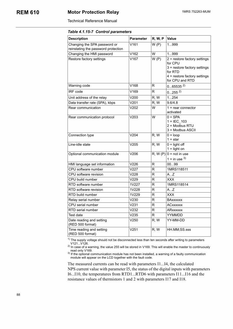
1MRS 752263-MUMMotor Protection Relay
Technical Reference Manual
REM 610
1) The supply voltage should not be disconnected less than ten seconds after writing to parameters V121...V126.
2) In case of a warning, the value 255 will be stored in V169. This will enable the master to continuously read only V169.
3) If the optional communication module has not been installed, a warning of a faulty communication module will appear on the LCD together with the fault code.
The measured currents can be read with parameters I1...I4, the calculated NPS current value with parameter I5, the status of the digital inputs with parameters I6...I10, the temperatures from RTD1...RTD6 with parameters I11...I16 and the resistance values of thermistors 1 and 2 with parameters I17 and I18.
Changing the SPA password or reinstating the password protection
V161 W (P) 1...999
Changing the HMI password V162 W 1...999Restore factory settings V167 W (P) 2 = restore factory settings
for CPU3 = restore factory settings for RTD4 = restore factory settings for CPU and RTD
Warning code V168 R 0...65535 2)
IRF code V169 R 0...255 2)
Unit address of the relay V200 R, W 1...254Data transfer rate (SPA), kbps V201 R, W 9.6/4.8Rear communication V202 W 1 = rear connector
activatedRear communication protocol V203 W 0 = SPA
1 = IEC_103 2 = Modbus RTU3 = Modbus ASCII
Connection type V204 R, W 0 = loop 1 = star
Line-idle state V205 R, W 0 = light off 1 = light on
Optional communication module V206 R, W (P) 0 = not in use1 = in use 3)
HMI language set information V226 R 00...99CPU software number V227 R 1MRS118511CPU software revision V228 R A...ZCPU build number V229 R XXXRTD software number 1V227 R 1MRS118514RTD software revision 1V228 R A...ZRTD build number 1V229 R XXXRelay serial number V230 R BAxxxxxxCPU serial number V231 R ACxxxxxxRTD serial number V232 R ARxxxxxxTest date V235 R YYMMDDDate reading and setting (RED 500 format)
V250 R, W YY-MM-DD
Time reading and setting (RED 500 format)
V251 R, W HH.MM;SS.sss
Table 4.1.15-7 Control parameters
Description Parameter R, W, P Value
88
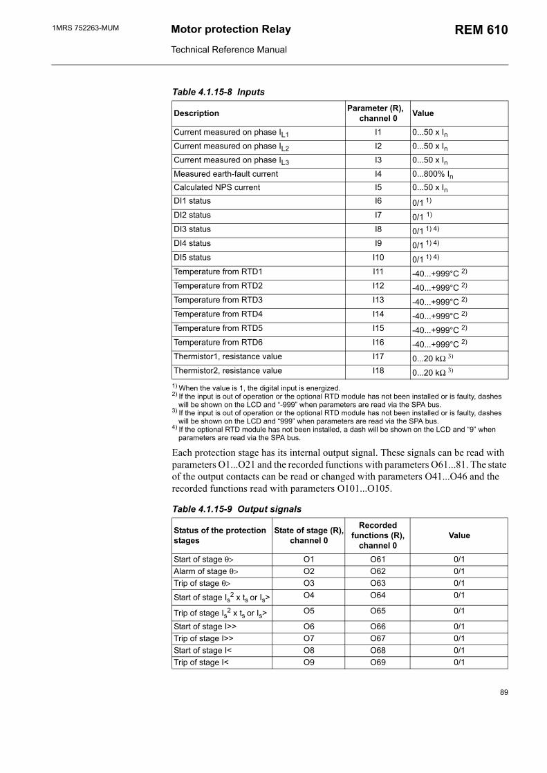
1MRS 752263-MUM Motor protection Relay
Technical Reference Manual
REM 610
Table 4.1.15-8 Inputs
Description Parameter (R),channel 0 Value
Current measured on phase IL1 I1 0...50 x InCurrent measured on phase IL2 I2 0...50 x InCurrent measured on phase IL3 I3 0...50 x InMeasured earth-fault current I4 0...800% InCalculated NPS current I5 0...50 x InDI1 status I6 0/1 1)
DI2 status I7 0/1 1)
DI3 status I8 0/1 1) 4)
DI4 status I9 0/1 1) 4)
DI5 status I10 0/1 1) 4)
Temperature from RTD1 I11 -40...+999°C 2)
Temperature from RTD2 I12 -40...+999°C 2)
Temperature from RTD3 I13 -40...+999°C 2)
Temperature from RTD4 I14 -40...+999°C 2)
Temperature from RTD5 I15 -40...+999°C 2)
Temperature from RTD6 I16 -40...+999°C 2)
Thermistor1, resistance value I17 0...20 kΩ 3)
Thermistor2, resistance value I18 0...20 kΩ 3)
1) When the value is 1, the digital input is energized.2) If the input is out of operation or the optional RTD module has not been installed or is faulty, dashes
will be shown on the LCD and -999 when parameters are read via the SPA bus.3) If the input is out of operation or the optional RTD module has not been installed or is faulty, dashes
will be shown on the LCD and 999 when parameters are read via the SPA bus.4) If the optional RTD module has not been installed, a dash will be shown on the LCD and 9 when
parameters are read via the SPA bus.
Each protection stage has its internal output signal. These signals can be read with parameters O1...O21 and the recorded functions with parameters O61...81. The state of the output contacts can be read or changed with parameters O41...O46 and the recorded functions read with parameters O101...O105.
Table 4.1.15-9 Output signals
Status of the protection stages
State of stage (R),channel 0
Recorded functions (R),
channel 0Value
Start of stage θ> O1 O61 0/1Alarm of stage θ> O2 O62 0/1Trip of stage θ> O3 O63 0/1
Start of stage Is2 x ts or Is> O4 O64 0/1
Trip of stage Is2 x ts or Is> O5 O65 0/1
Start of stage I>> O6 O66 0/1Trip of stage I>> O7 O67 0/1Start of stage I< O8 O68 0/1Trip of stage I< O9 O69 0/1
89
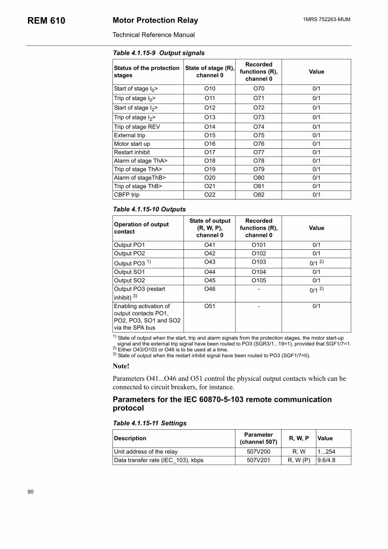
1MRS 752263-MUMMotor Protection Relay
Technical Reference Manual
REM 610
1) State of output when the start, trip and alarm signals from the protection stages, the motor start-up signal and the external trip signal have been routed to PO3 (SGR3/1...19=1), provided that SGF1/7=1.
2) Either O43/O103 or O46 is to be used at a time.3) State of output when the restart inhibit signal have been routed to PO3 (SGF1/7=0).
Note!
Parameters O41...O46 and O51 control the physical output contacts which can be connected to circuit breakers, for instance.
Parameters for the IEC 60870-5-103 remote communication protocol
Table 4.1.15-11 Settings
Description Parameter(channel 507) R, W, P Value
Unit address of the relay 507V200 R, W 1...254Data transfer rate (IEC_103), kbps 507V201 R, W (P) 9.6/4.8
Start of stage I0> O10 O70 0/1Trip of stage I0> O11 O71 0/1Start of stage I2> O12 O72 0/1Trip of stage I2> O13 O73 0/1Trip of stage REV O14 O74 0/1External trip O15 O75 0/1Motor start up O16 O76 0/1Restart inhibit O17 O77 0/1Alarm of stage ThA> O18 O78 0/1Trip of stage ThA> O19 O79 0/1Alarm of stageThB> O20 O80 0/1Trip of stage ThB> O21 O81 0/1CBFP trip O22 O82 0/1
Table 4.1.15-10 Outputs
Operation of output contact
State of output (R, W, P),channel 0
Recorded functions (R),
channel 0Value
Output PO1 O41 O101 0/1Output PO2 O42 O102 0/1
Output PO3 1) O43 O103 0/1 2)
Output SO1 O44 O104 0/1Output SO2 O45 O105 0/1Output PO3 (restart inhibit) 3)
O46 - 0/1 2)
Enabling activation of output contacts PO1, PO2, PO3, SO1 and SO2 via the SPA bus
O51 - 0/1
Table 4.1.15-9 Output signals
Status of the protection stages
State of stage (R),channel 0
Recorded functions (R),
channel 0Value
90
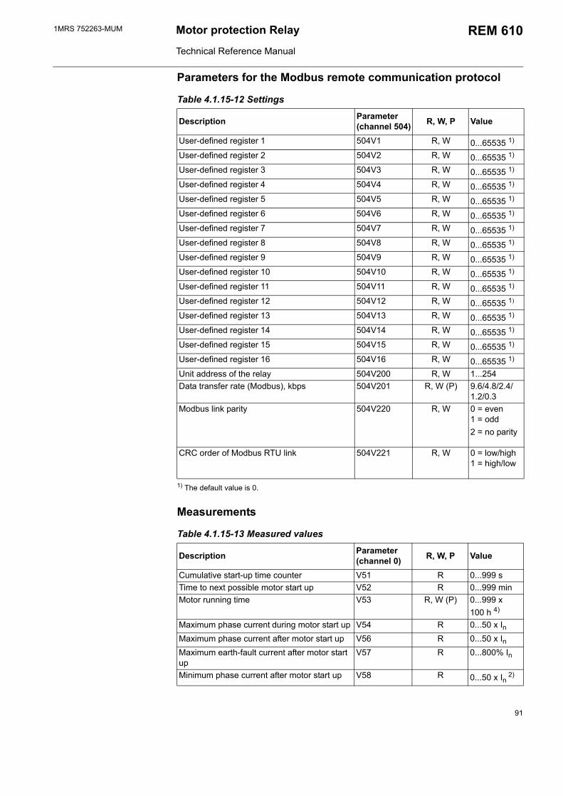
1MRS 752263-MUM Motor protection Relay
Technical Reference Manual
REM 610
Parameters for the Modbus remote communication protocol
Table 4.1.15-12 Settings
Description Parameter (channel 504) R, W, P Value
User-defined register 1 504V1 R, W 0...65535 1)
User-defined register 2 504V2 R, W 0...65535 1)
User-defined register 3 504V3 R, W 0...65535 1)
User-defined register 4 504V4 R, W 0...65535 1)
User-defined register 5 504V5 R, W 0...65535 1)
User-defined register 6 504V6 R, W 0...65535 1)
User-defined register 7 504V7 R, W 0...65535 1)
User-defined register 8 504V8 R, W 0...65535 1)
User-defined register 9 504V9 R, W 0...65535 1)
User-defined register 10 504V10 R, W 0...65535 1)
User-defined register 11 504V11 R, W 0...65535 1)
User-defined register 12 504V12 R, W 0...65535 1)
User-defined register 13 504V13 R, W 0...65535 1)
User-defined register 14 504V14 R, W 0...65535 1)
User-defined register 15 504V15 R, W 0...65535 1)
User-defined register 16 504V16 R, W 0...65535 1)
Unit address of the relay 504V200 R, W 1...254Data transfer rate (Modbus), kbps 504V201 R, W (P) 9.6/4.8/2.4/
1.2/0.3Modbus link parity 504V220 R, W 0 = even
1 = odd 2 = no parity
CRC order of Modbus RTU link 504V221 R, W 0 = low/high 1 = high/low
1) The default value is 0.
Measurements
Table 4.1.15-13 Measured values
Description Parameter(channel 0) R, W, P Value
Cumulative start-up time counter V51 R 0...999 sTime to next possible motor start up V52 R 0...999 minMotor running time V53 R, W (P) 0...999 x
100 h 4)
Maximum phase current during motor start up V54 R 0...50 x InMaximum phase current after motor start up V56 R 0...50 x InMaximum earth-fault current after motor start up
V57 R 0...800% In
Minimum phase current after motor start up V58 R 0...50 x In 2)
91
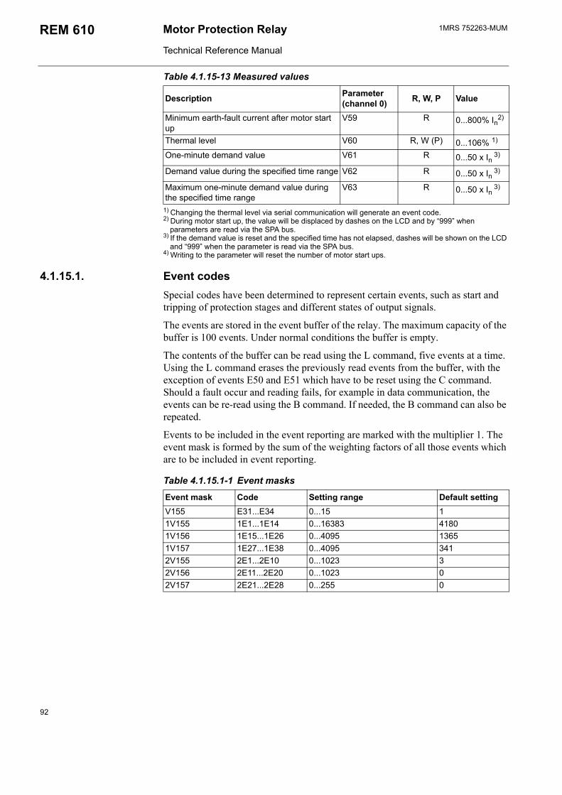
1MRS 752263-MUMMotor Protection Relay
Technical Reference Manual
REM 610
1) Changing the thermal level via serial communication will generate an event code.2) During motor start up, the value will be displaced by dashes on the LCD and by 999 when
parameters are read via the SPA bus.3) If the demand value is reset and the specified time has not elapsed, dashes will be shown on the LCD
and 999 when the parameter is read via the SPA bus.4) Writing to the parameter will reset the number of motor start ups.
4.1.15.1. Event codesSpecial codes have been determined to represent certain events, such as start and tripping of protection stages and different states of output signals.
The events are stored in the event buffer of the relay. The maximum capacity of the buffer is 100 events. Under normal conditions the buffer is empty.
The contents of the buffer can be read using the L command, five events at a time. Using the L command erases the previously read events from the buffer, with the exception of events E50 and E51 which have to be reset using the C command. Should a fault occur and reading fails, for example in data communication, the events can be re-read using the B command. If needed, the B command can also be repeated.
Events to be included in the event reporting are marked with the multiplier 1. The event mask is formed by the sum of the weighting factors of all those events which are to be included in event reporting.
Table 4.1.15.1-1 Event masks
Event mask Code Setting range Default settingV155 E31...E34 0...15 11V155 1E1...1E14 0...16383 41801V156 1E15...1E26 0...4095 13651V157 1E27...1E38 0...4095 3412V155 2E1...2E10 0...1023 32V156 2E11...2E20 0...1023 02V157 2E21...2E28 0...255 0
Minimum earth-fault current after motor start up
V59 R 0...800% In2)
Thermal level V60 R, W (P) 0...106% 1)
One-minute demand value V61 R 0...50 x In 3)
Demand value during the specified time range V62 R 0...50 x In 3)
Maximum one-minute demand value during the specified time range
V63 R 0...50 x In 3)
Table 4.1.15-13 Measured values
Description Parameter(channel 0) R, W, P Value
92
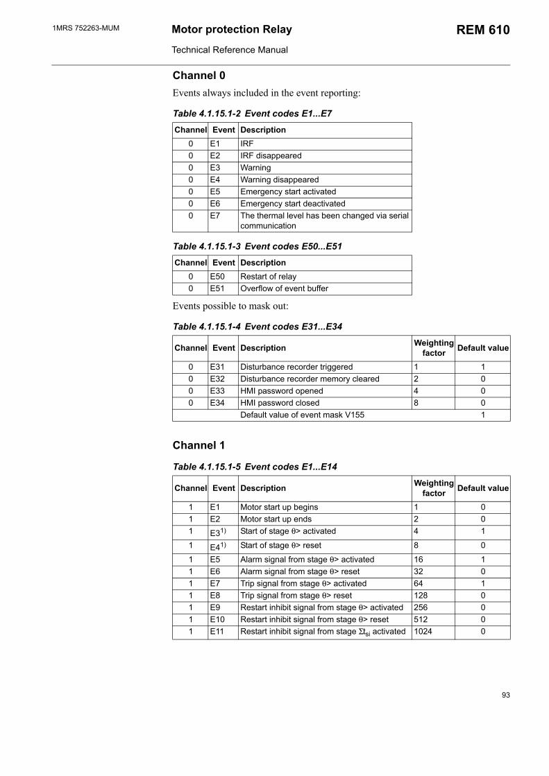
1MRS 752263-MUM Motor protection Relay
Technical Reference Manual
REM 610
Channel 0 Events always included in the event reporting:
Table 4.1.15.1-2 Event codes E1...E7
Channel Event Description0 E1 IRF0 E2 IRF disappeared0 E3 Warning0 E4 Warning disappeared0 E5 Emergency start activated0 E6 Emergency start deactivated0 E7 The thermal level has been changed via serial
communication
Table 4.1.15.1-3 Event codes E50...E51
Channel Event Description0 E50 Restart of relay0 E51 Overflow of event buffer
Events possible to mask out:
Table 4.1.15.1-4 Event codes E31...E34
Channel Event Description Weighting factor Default value
0 E31 Disturbance recorder triggered 1 10 E32 Disturbance recorder memory cleared 2 00 E33 HMI password opened 4 00 E34 HMI password closed 8 0
Default value of event mask V155 1
Channel 1
Table 4.1.15.1-5 Event codes E1...E14
Channel Event Description Weighting factor Default value
1 E1 Motor start up begins 1 01 E2 Motor start up ends 2 01 E31) Start of stage θ> activated 4 1
1 E41) Start of stage θ> reset 8 0
1 E5 Alarm signal from stage θ> activated 16 11 E6 Alarm signal from stage θ> reset 32 01 E7 Trip signal from stage θ> activated 64 11 E8 Trip signal from stage θ> reset 128 01 E9 Restart inhibit signal from stage θ> activated 256 01 E10 Restart inhibit signal from stage θ> reset 512 01 E11 Restart inhibit signal from stage Σtsi activated 1024 0
93
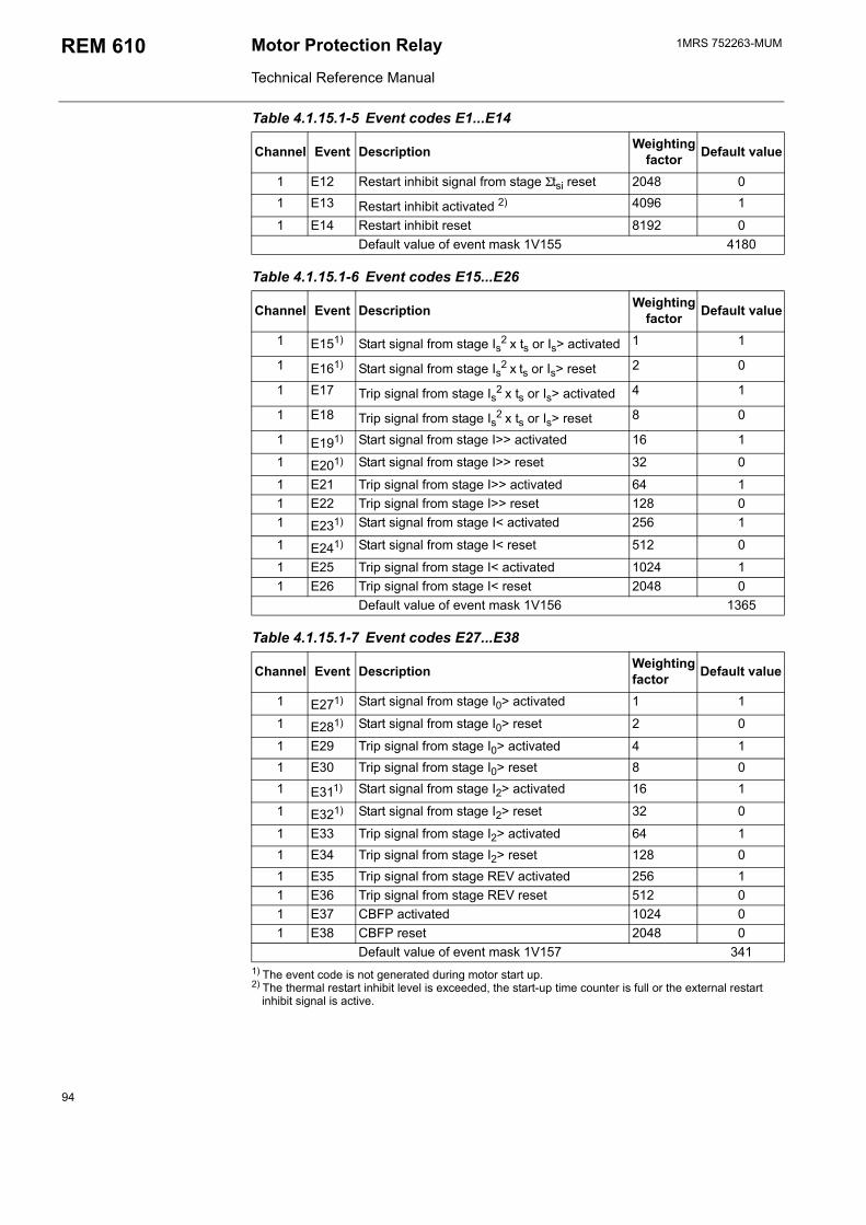
1MRS 752263-MUMMotor Protection Relay
Technical Reference Manual
REM 610
1) The event code is not generated during motor start up.2) The thermal restart inhibit level is exceeded, the start-up time counter is full or the external restart
inhibit signal is active.
1 E12 Restart inhibit signal from stage Σtsi reset 2048 01 E13 Restart inhibit activated 2) 4096 1
1 E14 Restart inhibit reset 8192 0Default value of event mask 1V155 4180
Table 4.1.15.1-6 Event codes E15...E26
Channel Event Description Weighting factor Default value
1 E151) Start signal from stage Is2 x ts or Is> activated 1 1
1 E161) Start signal from stage Is2 x ts or Is> reset 2 0
1 E17 Trip signal from stage Is2 x ts or Is> activated 4 1
1 E18 Trip signal from stage Is2 x ts or Is> reset 8 0
1 E191) Start signal from stage I>> activated 16 1
1 E201) Start signal from stage I>> reset 32 0
1 E21 Trip signal from stage I>> activated 64 11 E22 Trip signal from stage I>> reset 128 01 E231) Start signal from stage I< activated 256 1
1 E241) Start signal from stage I< reset 512 0
1 E25 Trip signal from stage I< activated 1024 11 E26 Trip signal from stage I< reset 2048 0
Default value of event mask 1V156 1365
Table 4.1.15.1-7 Event codes E27...E38
Channel Event Description Weighting factor Default value
1 E271) Start signal from stage I0> activated 1 1
1 E281) Start signal from stage I0> reset 2 0
1 E29 Trip signal from stage I0> activated 4 11 E30 Trip signal from stage I0> reset 8 01 E311) Start signal from stage I2> activated 16 1
1 E321) Start signal from stage I2> reset 32 0
1 E33 Trip signal from stage I2> activated 64 11 E34 Trip signal from stage I2> reset 128 01 E35 Trip signal from stage REV activated 256 11 E36 Trip signal from stage REV reset 512 01 E37 CBFP activated 1024 01 E38 CBFP reset 2048 0
Default value of event mask 1V157 341
Table 4.1.15.1-5 Event codes E1...E14
Channel Event Description Weighting factor Default value
94
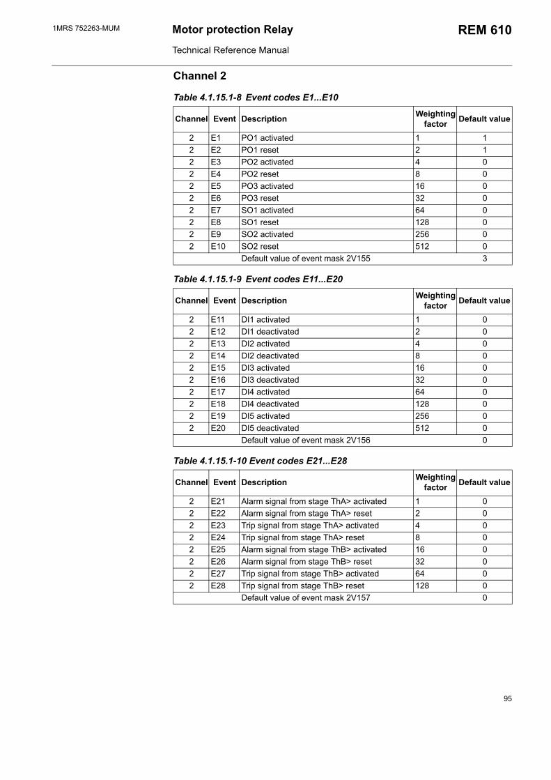
1MRS 752263-MUM Motor protection Relay
Technical Reference Manual
REM 610
Channel 2
Table 4.1.15.1-8 Event codes E1...E10
Channel Event Description Weighting factor Default value
2 E1 PO1 activated 1 12 E2 PO1 reset 2 12 E3 PO2 activated 4 02 E4 PO2 reset 8 02 E5 PO3 activated 16 02 E6 PO3 reset 32 02 E7 SO1 activated 64 02 E8 SO1 reset 128 02 E9 SO2 activated 256 02 E10 SO2 reset 512 0
Default value of event mask 2V155 3
Table 4.1.15.1-9 Event codes E11...E20
Channel Event Description Weighting factor Default value
2 E11 DI1 activated 1 02 E12 DI1 deactivated 2 02 E13 DI2 activated 4 02 E14 DI2 deactivated 8 02 E15 DI3 activated 16 02 E16 DI3 deactivated 32 02 E17 DI4 activated 64 02 E18 DI4 deactivated 128 02 E19 DI5 activated 256 02 E20 DI5 deactivated 512 0
Default value of event mask 2V156 0
Table 4.1.15.1-10 Event codes E21...E28
Channel Event Description Weighting factor Default value
2 E21 Alarm signal from stage ThA> activated 1 02 E22 Alarm signal from stage ThA> reset 2 02 E23 Trip signal from stage ThA> activated 4 02 E24 Trip signal from stage ThA> reset 8 02 E25 Alarm signal from stage ThB> activated 16 02 E26 Alarm signal from stage ThB> reset 32 02 E27 Trip signal from stage ThB> activated 64 02 E28 Trip signal from stage ThB> reset 128 0
Default value of event mask 2V157 0
95
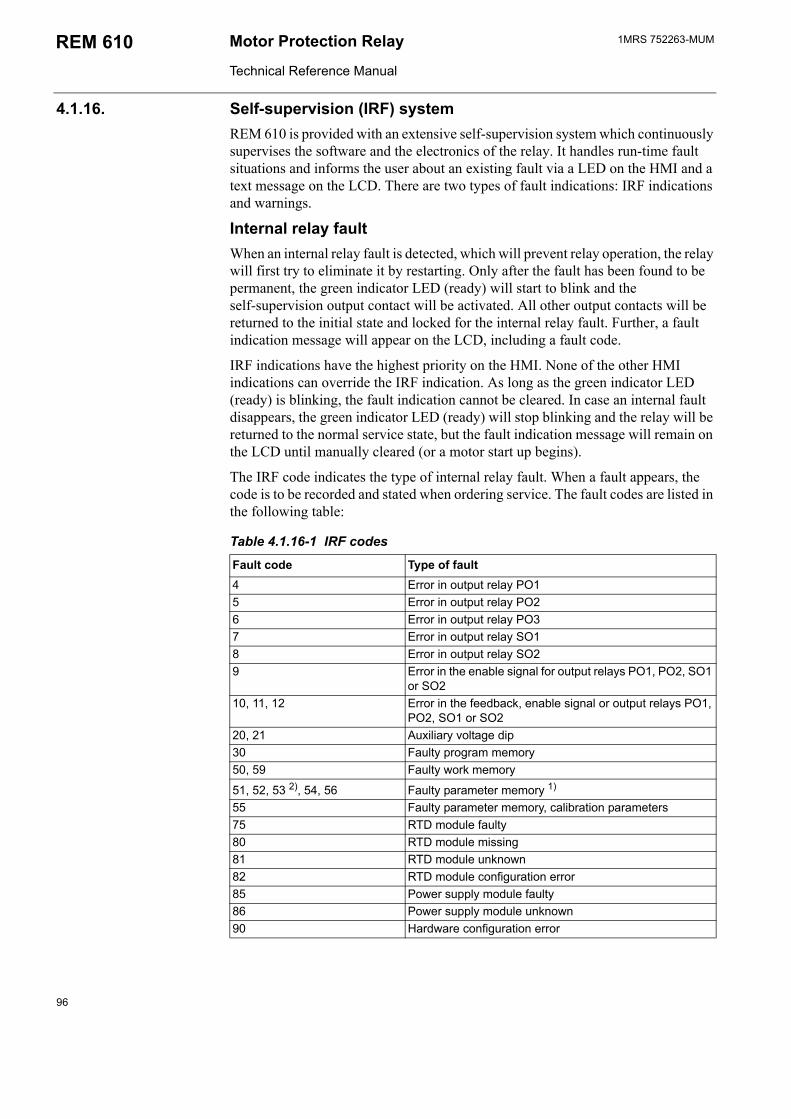
1MRS 752263-MUMMotor Protection Relay
Technical Reference Manual
REM 610
4.1.16. Self-supervision (IRF) system REM 610 is provided with an extensive self-supervision system which continuously supervises the software and the electronics of the relay. It handles run-time fault situations and informs the user about an existing fault via a LED on the HMI and a text message on the LCD. There are two types of fault indications: IRF indications and warnings.
Internal relay faultWhen an internal relay fault is detected, which will prevent relay operation, the relay will first try to eliminate it by restarting. Only after the fault has been found to be permanent, the green indicator LED (ready) will start to blink and the self-supervision output contact will be activated. All other output contacts will be returned to the initial state and locked for the internal relay fault. Further, a fault indication message will appear on the LCD, including a fault code.
IRF indications have the highest priority on the HMI. None of the other HMI indications can override the IRF indication. As long as the green indicator LED (ready) is blinking, the fault indication cannot be cleared. In case an internal fault disappears, the green indicator LED (ready) will stop blinking and the relay will be returned to the normal service state, but the fault indication message will remain on the LCD until manually cleared (or a motor start up begins).
The IRF code indicates the type of internal relay fault. When a fault appears, the code is to be recorded and stated when ordering service. The fault codes are listed in the following table:
Table 4.1.16-1 IRF codes
Fault code Type of fault4 Error in output relay PO15 Error in output relay PO26 Error in output relay PO37 Error in output relay SO18 Error in output relay SO29 Error in the enable signal for output relays PO1, PO2, SO1
or SO210, 11, 12 Error in the feedback, enable signal or output relays PO1,
PO2, SO1 or SO220, 21 Auxiliary voltage dip30 Faulty program memory50, 59 Faulty work memory
51, 52, 53 2), 54, 56 Faulty parameter memory 1)
55 Faulty parameter memory, calibration parameters75 RTD module faulty80 RTD module missing81 RTD module unknown82 RTD module configuration error85 Power supply module faulty86 Power supply module unknown90 Hardware configuration error
96
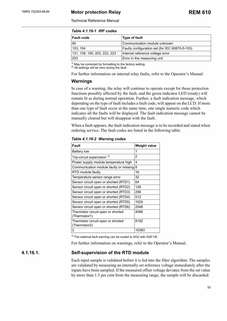
1MRS 752263-MUM Motor protection Relay
Technical Reference Manual
REM 610
1) May be corrected by formatting to the factory setting.2) All settings will be zero during the fault.
For further information on internal relay faults, refer to the Operators Manual.
WarningsIn case of a warning, the relay will continue to operate except for those protection functions possibly affected by the fault, and the green indicator LED (ready) will remain lit as during normal operation. Further, a fault indication message, which depending on the type of fault includes a fault code, will appear on the LCD. If more than one type of fault occur at the same time, one single numeric code which indicates all the faults will be displayed. The fault indication message cannot be manually cleared but will disappear with the fault.
When a fault appears, the fault indication message is to be recorded and stated when ordering service. The fault codes are listed in the following table:
Table 4.1.16-2 Warning codes
Fault Weight valueBattery low 1
Trip-circuit supervision 1) 2
Power supply module temperature high 4Communication module faulty or missing 8RTD module faulty 16Temperature sensor range error 32Sensor circuit open or shorted (RTD1) 64Sensor circuit open or shorted (RTD2) 128Sensor circuit open or shorted (RTD3) 256Sensor circuit open or shorted (RTD4) 512Sensor circuit open or shorted (RTD5) 1024Sensor circuit open or shorted (RTD6) 2048Thermistor circuit open or shorted (Thermistor1)
4096
Thermistor circuit open or shorted (Thermistor2)
8192
Σ 16383
1) The external fault warning can be routed to SO2 with SGF1/8.
For further information on warnings, refer to the Operators Manual.
4.1.16.1. Self-supervision of the RTD moduleEach input sample is validated before it is fed into the filter algorithm. The samples are validated by measuring an internally set reference voltage immediately after the inputs have been sampled. If the measured offset voltage deviates from the set value by more than 1.5 per cent from the measuring range, the sample will be discarded.
95 Communication module unknown103, 104 Faulty configuration set (for IEC 60870-5-103)131, 139, 195, 203, 222, 223 Internal reference voltage error253 Error in the measuring unit
Table 4.1.16-1 IRF codes
Fault code Type of fault
97
1MRS 752263-MUMMotor Protection Relay
Technical Reference Manual
REM 610
If the fault has not disappeared on expiration of the filter time of eight seconds, all inputs will automatically be set out of operation to indicate a hardware fault. Should the fault later disappear, the inputs will be re-enabled. This will prevent most sudden hardware faults from affecting the measured value.
To ensure that the specified measurement accuracy is achieved, a more thorough test of the hardware will be performed as part of the continuous self-calibration procedure to identify errors which degrade the measurement accuracy. If the self-calibration of the RTD module fails, all inputs will automatically be set out of operation to indicate a hardware fault. Should the self-calibration later succeed, the inputs will be re-enabled.
Additionally, a single input will be set out of operation if the measured value is outside the specified limits (-4%...104%) or if an open-loop or a short-circuit condition is detected.
4.1.17. Relay parameterizationLocal parameterizationThe parameters of the relay can be set either locally via the HMI or externally via serial communication with the Relay Setting Tool. When the parameters are set locally, the setting parameters can be chosen via the hierarchical menu structure. The desired language can be selected for parameter descriptions. Refer to the Operators Manual for further information.
External parameterizationThe Relay Setting Tool is used for parameterizing the relay units. Adjusting the parameter values using the Relay Setting Tool is done off-line, after which the parameters can be downloaded to the relay via a communication port.
4.2. Design description
4.2.1. Input/output connectionsAll external circuits are connected to the terminals on the rear panel of the relay. Terminals X2.1-_ are dimensioned for one 0.5...6.0 mm2 wire or for two max 2.5 mm2 wires and terminals X3.1-_ and X4.1-_ for one 0.2...2.5 mm2 wire or for two 0.2...1.0 mm2 wires.
The energizing phase currents of REM 610 are connected to terminals X2.1/1-2, X2.1/3-4 and X2.1/5-6 (see table 4.2.1-1). The relay can also be used in single or two-phase applications by leaving one or two energizing inputs unoccupied.
The energizing earth-fault current of REM 610 is connected to terminals X2.1/7-8 (see table 4.2.1-1).
The input terminals of the optional RTD module are located on connection socket X3.1. The RTD sensors or thermistors are connected to terminals X3.1/7-24 (see table 4.2.1-6). Both the inner and the outer shield of the cable must be connected to the chassis earth screw between connectors X4.1 and X3.1 (lower screw). In addition, the outer shield must be connected to chassis earth at the other end of the cable as well.
98
1MRS 752263-MUM Motor protection Relay
Technical Reference Manual
REM 610
Note!
Unused RTD inputs are to be short-circuited separately.
Note!
REM 610 is provided with connection socket X3.1 only if the optional RTD module has been installed.
Terminals X4.1/21-24 and X3.1/1-6 (optional) are digital input terminals (see table 4.2.1-5). The digital inputs can be used to generate a blocking signal, to unlatch output contacts or for remote control of relay settings, for instance. The requested functions are selected separately for each input in switchgroups SGB1...5. The digital inputs can also be used to trigger the disturbance recorder; this function is selected with SPA parameter V243.
The auxiliary voltage of the relay is connected to terminals X4.1/1-2 (see table 4.2.1-2). At dc supply, the positive lead is connected to terminal X4.1/1. The permitted auxiliary voltage range of the relay is marked on the front panel of the relay under the handle of the plug-in unit.
Output contacts PO1, PO2 and PO3 (restart inhibit) are heavy-duty trip contacts capable of controlling most circuit breakers (see table 4.2.1-4). The trip signals from the different protection stages are routed to the power outputs with the switches of switchgroups SGR1...SGR3. On delivery from the factory, the trip signals from all the protection stages except ThA> and ThB> are routed to both PO1 and PO2 and the restart inhibit signal to PO3.
Output contacts SO1 and SO2 can be used for signalling on start and tripping of the relay (see table 4.2.1-4). The signals to be routed to signal outputs SO1 and SO2 are selected with the switches of switchgroups SGR4 and SGR5. On delivery from the factory, the start and alarm signals from all the protection stages except ThA> and ThB> are routed to both SO1 and SO2.
The IRF contact functions as an output contact for the self-supervision system of the protection relay (see table 4.2.1-3). Under normal operating conditions the relay is energized and the contact closed (X4.1/3-5). When a fault is detected by the self-supervision system or the auxiliary voltage is disconnected, the output contact will drop off and the contact close (X4.1/3-4).
Fig. 4.2.1.-1 and Fig. 4.2.1.-2 present a rear view of REM 610, showing four connecting sockets: one for measuring transformers, one for the optional RTD module, one for power supply and one for optional serial communication.
99
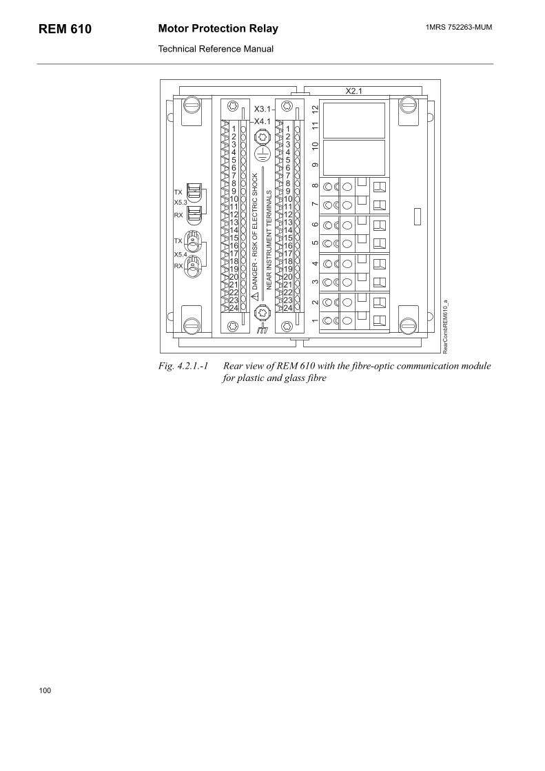
1MRS 752263-MUMMotor Protection Relay
Technical Reference Manual
REM 610
/ /
/ /
/
??
/0,
<8$.1(@(#->1A1
:(
#B-
$18($
#:(
C21$::1(2$8A#
D
)
'4
5 *+,
/
/
/60
/60
/
/
Fig. 4.2.1.-1 Rear view of REM 610 with the fibre-optic communication module for plastic and glass fibre
100
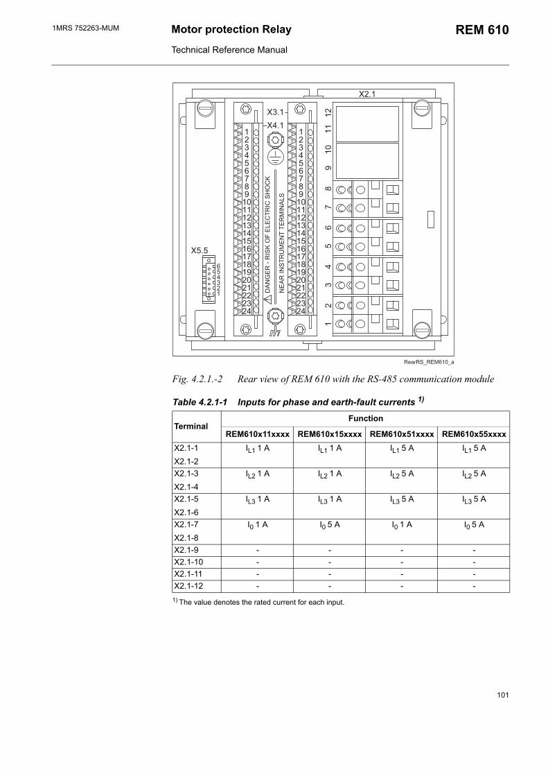
1MRS 752263-MUM Motor protection Relay
Technical Reference Manual
REM 610
<8$.1(@(#->1A1
:(
#B-
$18($
#:(
C21$::1(2$8A#
D
/ /
/ /
/
?
?
?
?
) & *+,
Fig. 4.2.1.-2 Rear view of REM 610 with the RS-485 communication module
Table 4.2.1-1 Inputs for phase and earth-fault currents 1)
TerminalFunction
REM610x11xxxx REM610x15xxxx REM610x51xxxx REM610x55xxxxX2.1-1 IL1 1 A IL1 1 A IL1 5 A IL1 5 AX2.1-2X2.1-3 IL2 1 A IL2 1 A IL2 5 A IL2 5 AX2.1-4X2.1-5 IL3 1 A IL3 1 A IL3 5 A IL3 5 AX2.1-6X2.1-7 I0 1 A I0 5 A I0 1 A I0 5 AX2.1-8X2.1-9 - - - -X2.1-10 - - - -X2.1-11 - - - -X2.1-12 - - - -
1) The value denotes the rated current for each input.
101
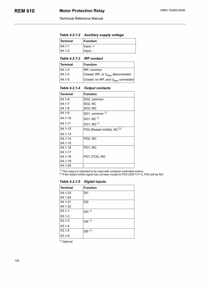
1MRS 752263-MUMMotor Protection Relay
Technical Reference Manual
REM 610
Table 4.2.1-2 Auxiliary supply voltage
Terminal FunctionX4.1-1 Input, +X4.1-2 Input, -
Table 4.2.1-3 IRF contact
Terminal FunctionX4.1-3 IRF, commonX4.1-4 Closed; IRF, or Uaux disconnected
X4.1-5 Closed; no IRF, and Uaux connected
Table 4.2.1-4 Output contacts
Terminal FunctionX4.1-6 SO2, commonX4.1-7 SO2, NCX4.1-8 SO2, NOX4.1-9 SO1, common 1)
X4.1-10 SO1, NC 1)
X4.1-11 SO1, NO 1)
X4.1-12 PO3 (Restart Inhibit), NC 2)
X4.1-13X4.1-14 PO2, NOX4.1-15X4.1-16 PO1, NOX4.1-17X4.1-18 PO1 (TCS), NOX4.1-19X4.1-20 -
1) This output is intended to be used with contactor controlled motors.2) If the restart inhibit signal has not been routed to PO3 (SGF1/7=1), PO3 will be NO.
Table 4.2.1-5 Digital inputs
Terminal FunctionX4.1-23 DI1X4.1-24X4.1-21 DI2X4.1-22X3.1-1 DI3 1)
X3.1-2X3.1-3 DI4 1)
X3.1-4X3.1-5 DI5 1)
X3.1-6
1) Optional
102
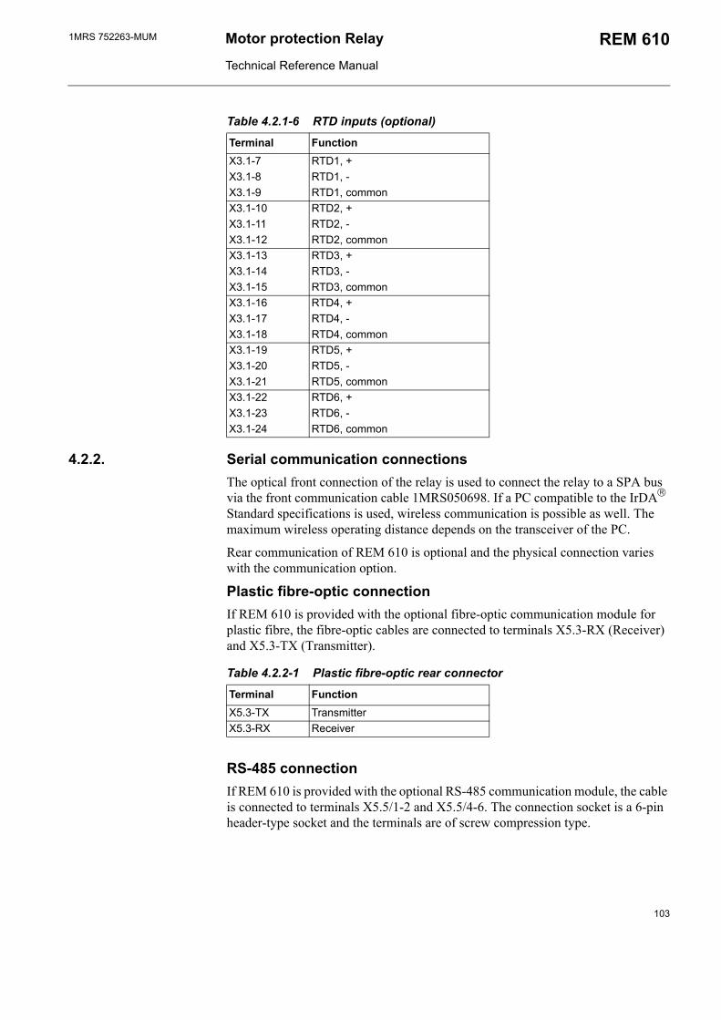
1MRS 752263-MUM Motor protection Relay
Technical Reference Manual
REM 610
Table 4.2.1-6 RTD inputs (optional)
Terminal FunctionX3.1-7 RTD1, +X3.1-8 RTD1, -X3.1-9 RTD1, commonX3.1-10 RTD2, +X3.1-11 RTD2, -X3.1-12 RTD2, commonX3.1-13 RTD3, +X3.1-14 RTD3, -X3.1-15 RTD3, commonX3.1-16 RTD4, +X3.1-17 RTD4, -X3.1-18 RTD4, commonX3.1-19 RTD5, +X3.1-20 RTD5, -X3.1-21 RTD5, commonX3.1-22 RTD6, +X3.1-23 RTD6, -X3.1-24 RTD6, common
4.2.2. Serial communication connectionsThe optical front connection of the relay is used to connect the relay to a SPA bus via the front communication cable 1MRS050698. If a PC compatible to the IrDA Standard specifications is used, wireless communication is possible as well. The maximum wireless operating distance depends on the transceiver of the PC.
Rear communication of REM 610 is optional and the physical connection varies with the communication option.
Plastic fibre-optic connectionIf REM 610 is provided with the optional fibre-optic communication module for plastic fibre, the fibre-optic cables are connected to terminals X5.3-RX (Receiver) and X5.3-TX (Transmitter).
Table 4.2.2-1 Plastic fibre-optic rear connector
Terminal FunctionX5.3-TX TransmitterX5.3-RX Receiver
RS-485 connectionIf REM 610 is provided with the optional RS-485 communication module, the cable is connected to terminals X5.5/1-2 and X5.5/4-6. The connection socket is a 6-pin header-type socket and the terminals are of screw compression type.
103
1MRS 752263-MUMMotor Protection Relay
Technical Reference Manual
REM 610
The RS-485 communication module follows the TIA/EIA-485 standard and is intended to be used in a Daisy-chain bus wiring scheme with 2-wire, half-duplex, multi-point communication. The maximum number of devices (nodes) connected to the bus where REM 610 is being used is 32, and the maximum length of the bus is 1200 meters.
When connecting REM610 to the bus, a quality twisted pair shielded cable is to be used. The conductors of the pair are connected to A and B. If signal ground is being used for balancing potential differences between devices/nodes, a quality dual twisted pair shielded cable is to be used. In this case, one pair is connected to A and B, and one of the conductors of the other pair to signal ground. When connecting one device to another, A is connected to A and B to B.
The cable shield is to be connected directly to earth (shield GND) in one point/device of the bus. Other devices connected to the bus should have the cable shield connected to earth via a capacitor (shield GND via capacitor).
Note!
Signal ground can only be used for balancing potential differences between devices/nodes if all devices connected to the bus have isolated RS-485 interfaces.
The RS-485 communication module is provided with jumpers for setting bus termination and fail-safe biasing. The bus is to be terminated at both ends, which can be done by using the internal termination resistor on the communication module. The termination resistor is selected by setting jumper X5 to the ON position. If the internal termination resistor of 120 Ω is used, the impedance of the cable should be the same.
The bus is to be biased at one end to ensure fail-safe operation, which can be done using the pull-up and pull-down resistors on the communication module. The pull-up and pull-down resistors are selected by setting jumpers X3 and X4 to the ON position.
The jumpers have been set to no termination (X5 in the OFF position) and no biasing (X3 and X4 in the OFF position) as default.
104

1MRS 752263-MUM Motor protection Relay
Technical Reference Manual
REM 610
*::*+
*::*+
*::*+
F<39-#. /
Fig. 4.2.2.-1 Jumper location on the RS-485 communication module
Table 4.2.2-2 RS-485 rear connector
Terminal FunctionX5.5-6 Data A (+)X5.5-5 Data B (-)X5.5-4 Signal GND (for potential balancing)X5.5-3 -X5.5-2 Shield GND (via capacitor)X5.5-1 Shield GND
Combined fibre-optic connection (plastic and glass)If REM 610 is provided with the optional fibre-optic communication module for plastic and glass fibre, the plastic fibre-optic cables are connected to terminals X5.3-RX (Receiver) and X5.3-TX (Transmitter) and the glass fibre-optic cables to terminals X5.4-RX (Receiver) and X5.4-TX (Transmitter).
The fibre-optic interface is selected with jumpers X6 and X2 located on the PCB of the communication module (see Fig. 4.2.2.-2).
Table 4.2.2-3 Transmitter selection
Transmitter Position of jumper X6 Plastic X5.3-TXGlass X5.4-TX
105
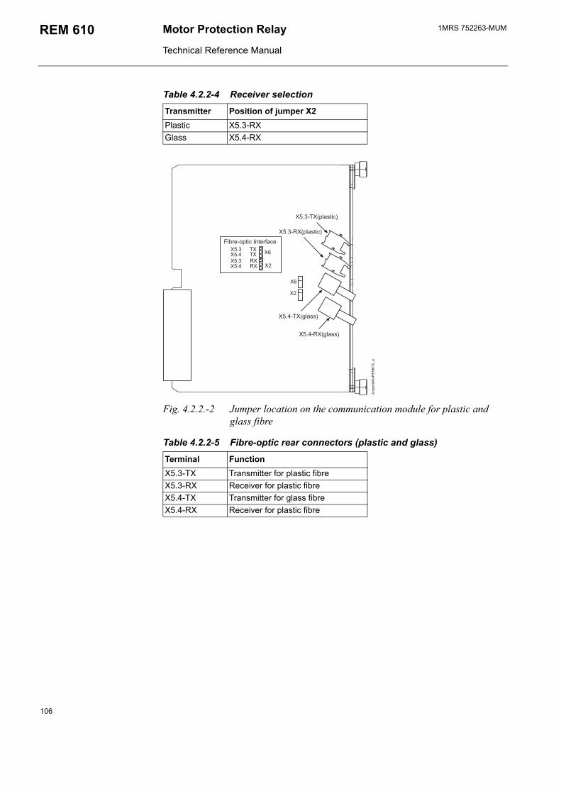
1MRS 752263-MUMMotor Protection Relay
Technical Reference Manual
REM 610
Table 4.2.2-4 Receiver selection
Transmitter Position of jumper X2 Plastic X5.3-RXGlass X5.4-RX
/+
/
/60/60
// /+
//60/60
/ /
7()$*
1 *+,
/60 # /8$$9
/60 #/8$$9
5)#'(:);:)
/60#/8($:9
/60# /8($:9
Fig. 4.2.2.-2 Jumper location on the communication module for plastic and glass fibre
Table 4.2.2-5 Fibre-optic rear connectors (plastic and glass)
Terminal FunctionX5.3-TX Transmitter for plastic fibreX5.3-RX Receiver for plastic fibreX5.4-TX Transmitter for glass fibreX5.4-RX Receiver for plastic fibre
106
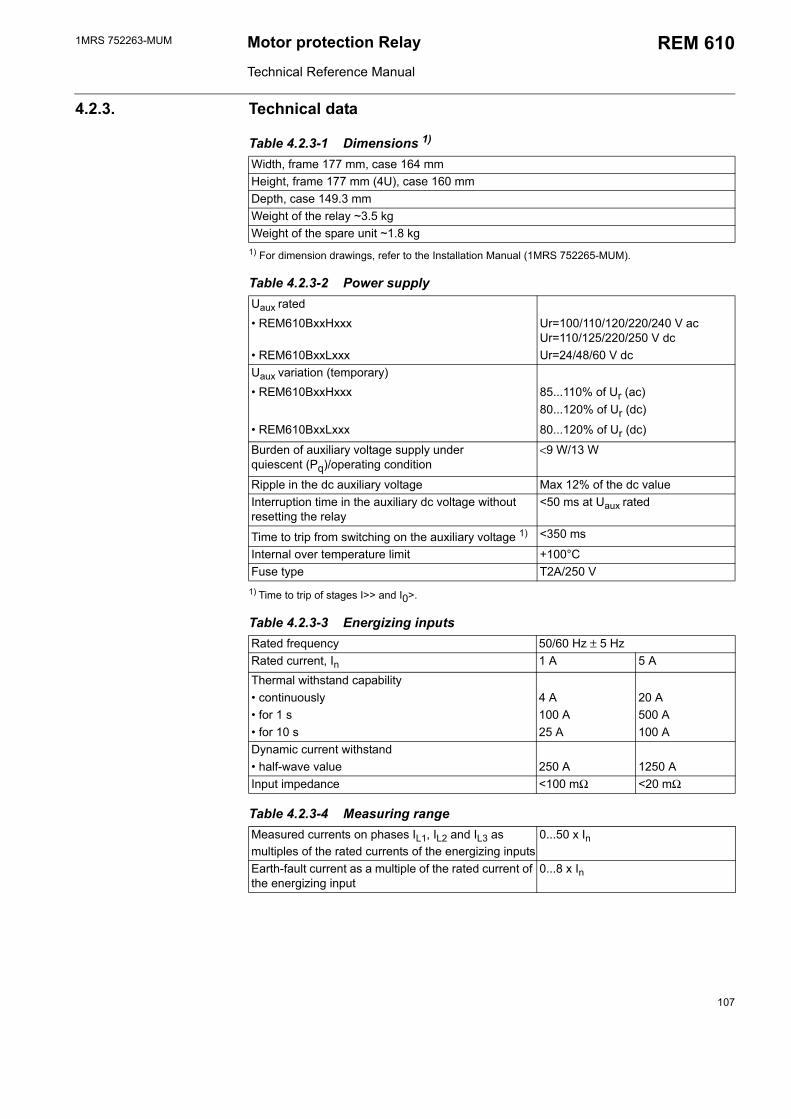
1MRS 752263-MUM Motor protection Relay
Technical Reference Manual
REM 610
4.2.3. Technical data
Table 4.2.3-1 Dimensions 1)
Width, frame 177 mm, case 164 mmHeight, frame 177 mm (4U), case 160 mmDepth, case 149.3 mmWeight of the relay ~3.5 kgWeight of the spare unit ~1.8 kg
1) For dimension drawings, refer to the Installation Manual (1MRS 752265-MUM).
Table 4.2.3-2 Power supplyUaux rated REM610BxxHxxx Ur=100/110/120/220/240 V ac
Ur=110/125/220/250 V dc REM610BxxLxxx Ur=24/48/60 V dcUaux variation (temporary) REM610BxxHxxx 85...110% of Ur (ac)
80...120% of Ur (dc)
REM610BxxLxxx 80...120% of Ur (dc)
Burden of auxiliary voltage supply under quiescent (Pq)/operating condition
<9 W/13 W
Ripple in the dc auxiliary voltage Max 12% of the dc valueInterruption time in the auxiliary dc voltage without resetting the relay
<50 ms at Uaux rated
Time to trip from switching on the auxiliary voltage 1) <350 ms
Internal over temperature limit +100°CFuse type T2A/250 V
1) Time to trip of stages I>> and I0>.
Table 4.2.3-3 Energizing inputsRated frequency 50/60 Hz ± 5 HzRated current, In 1 A 5 AThermal withstand capability continuously 4 A 20 A for 1 s 100 A 500 A for 10 s 25 A 100 ADynamic current withstand half-wave value 250 A 1250 AInput impedance <100 mΩ <20 mΩ
Table 4.2.3-4 Measuring rangeMeasured currents on phases IL1, IL2 and IL3 as multiples of the rated currents of the energizing inputs
0...50 x In
Earth-fault current as a multiple of the rated current of the energizing input
0...8 x In
107
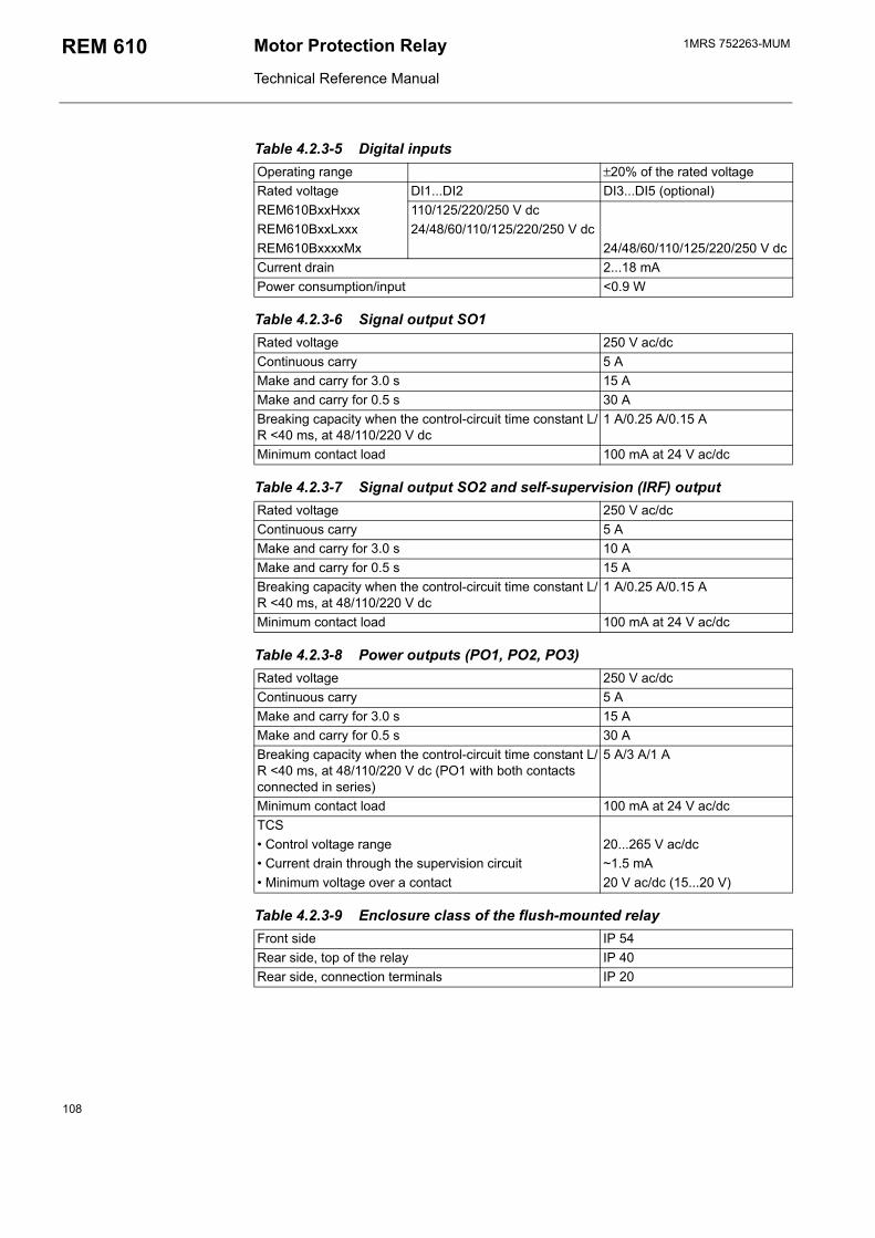
1MRS 752263-MUMMotor Protection Relay
Technical Reference Manual
REM 610
Table 4.2.3-5 Digital inputsOperating range ±20% of the rated voltageRated voltage DI1...DI2 DI3...DI5 (optional)REM610BxxHxxx 110/125/220/250 V dcREM610BxxLxxx 24/48/60/110/125/220/250 V dcREM610BxxxxMx 24/48/60/110/125/220/250 V dcCurrent drain 2...18 mAPower consumption/input <0.9 W
Table 4.2.3-6 Signal output SO1Rated voltage 250 V ac/dcContinuous carry 5 AMake and carry for 3.0 s 15 AMake and carry for 0.5 s 30 ABreaking capacity when the control-circuit time constant L/R <40 ms, at 48/110/220 V dc
1 A/0.25 A/0.15 A
Minimum contact load 100 mA at 24 V ac/dc
Table 4.2.3-7 Signal output SO2 and self-supervision (IRF) outputRated voltage 250 V ac/dcContinuous carry 5 AMake and carry for 3.0 s 10 AMake and carry for 0.5 s 15 ABreaking capacity when the control-circuit time constant L/R <40 ms, at 48/110/220 V dc
1 A/0.25 A/0.15 A
Minimum contact load 100 mA at 24 V ac/dc
Table 4.2.3-8 Power outputs (PO1, PO2, PO3)Rated voltage 250 V ac/dcContinuous carry 5 AMake and carry for 3.0 s 15 AMake and carry for 0.5 s 30 ABreaking capacity when the control-circuit time constant L/R <40 ms, at 48/110/220 V dc (PO1 with both contacts connected in series)
5 A/3 A/1 A
Minimum contact load 100 mA at 24 V ac/dcTCS Control voltage range 20...265 V ac/dc Current drain through the supervision circuit ~1.5 mA Minimum voltage over a contact 20 V ac/dc (15...20 V)
Table 4.2.3-9 Enclosure class of the flush-mounted relayFront side IP 54Rear side, top of the relay IP 40Rear side, connection terminals IP 20
108
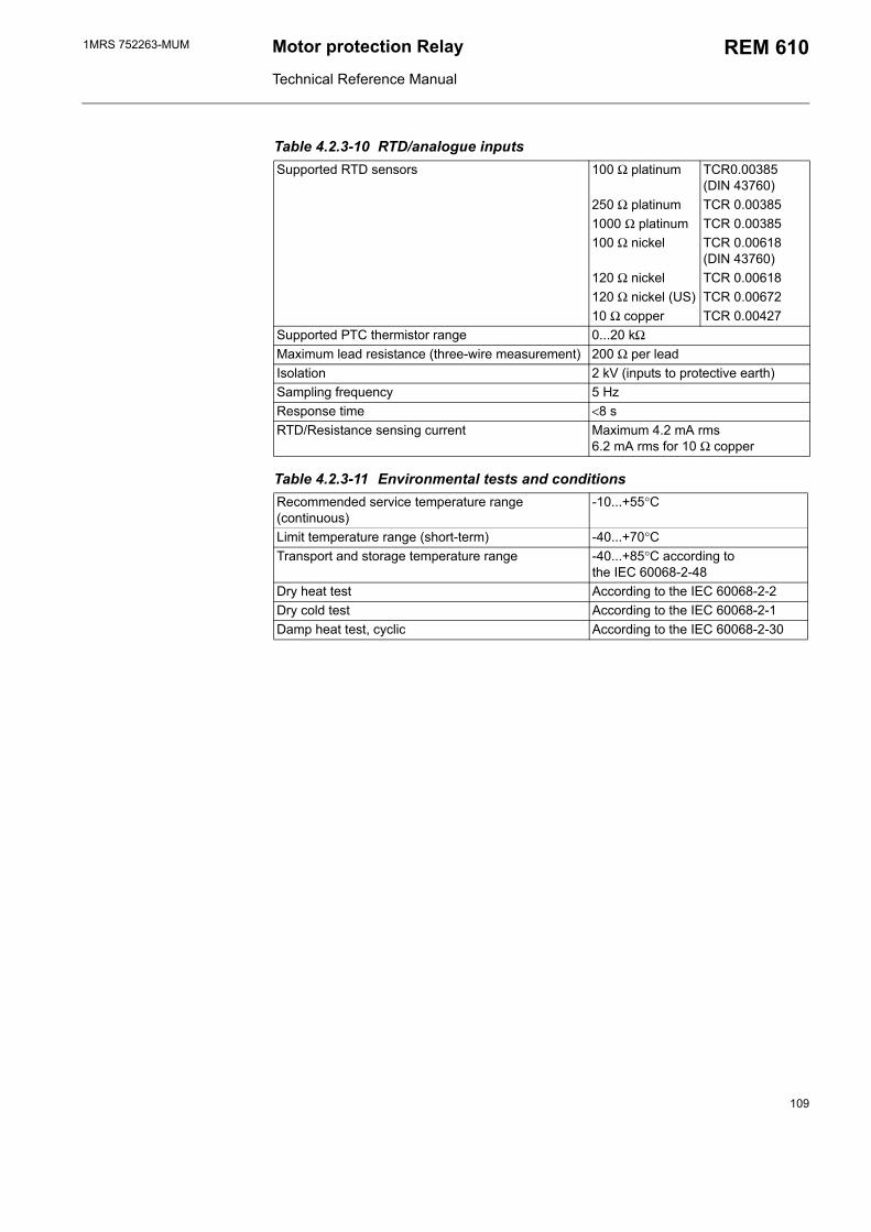
1MRS 752263-MUM Motor protection Relay
Technical Reference Manual
REM 610
Table 4.2.3-10 RTD/analogue inputsSupported RTD sensors 100 Ω platinum TCR0.00385
(DIN 43760)250 Ω platinum TCR 0.003851000 Ω platinum TCR 0.00385100 Ω nickel TCR 0.00618
(DIN 43760)120 Ω nickel TCR 0.00618120 Ω nickel (US) TCR 0.0067210 Ω copper TCR 0.00427
Supported PTC thermistor range 0...20 kΩMaximum lead resistance (three-wire measurement) 200 Ω per leadIsolation 2 kV (inputs to protective earth)Sampling frequency 5 HzResponse time <8 sRTD/Resistance sensing current Maximum 4.2 mA rms
6.2 mA rms for 10 Ω copper
Table 4.2.3-11 Environmental tests and conditionsRecommended service temperature range (continuous)
-10...+55°C
Limit temperature range (short-term) -40...+70°CTransport and storage temperature range -40...+85°C according to
the IEC 60068-2-48Dry heat test According to the IEC 60068-2-2Dry cold test According to the IEC 60068-2-1Damp heat test, cyclic According to the IEC 60068-2-30
109
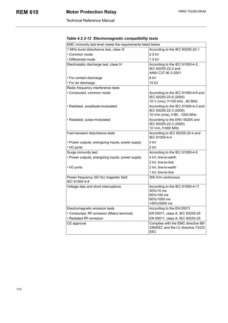
1MRS 752263-MUMMotor Protection Relay
Technical Reference Manual
REM 610
Table 4.2.3-12 Electromagnetic compatibility testsEMC immunity test level meets the requirements listed below1 MHz burst disturbance test, class III According to the IEC 60255-22-1 Common mode 2.5 kV Differential mode 1.0 kVElectrostatic discharge test, class IV According to the IEC 61000-4-2,
IEC 60255-22-2 and ANSI C37.90.3-2001
For contact discharge 8 kV For air discharge 15 kVRadio frequency interference tests Conducted, common mode According to the IEC 61000-4-6 and
IEC 60255-22-6 (2000)10 V (rms), f=150 kHz...80 MHz
Radiated, amplitude-modulated According to the IEC 61000-4-3 and IEC 60255-22-3 (2000)10 V/m (rms), f=80...1000 MHz
Radiated, pulse-modulated According to the ENV 50204 and IEC 60255-22-3 (2000)10 V/m, f=900 MHz
Fast transient disturbance tests According to IEC 60255-22-4 and IEC 61000-4-4
Power outputs, energizing inputs, power supply 4 kV I/O ports 2 kVSurge immunity test According to the IEC 61000-4-5 Power outputs, energizing inputs, power supply 4 kV, line-to-earth
2 kV, line-to-line I/O ports 2 kV, line-to-earth
1 kV, line-to-linePower frequency (50 Hz) magnetic field IEC 61000-4-8
300 A/m continuous
Voltage dips and short interruptions According to the IEC 61000-4-1130%/10 ms60%/100 ms60%/1000 ms>95%/5000 ms
Electromagnetic emission tests According to the EN 55011 Conducted, RF-emission (Mains terminal) EN 55011, class A, IEC 60255-25 Radiated RF-emission EN 55011, class A, IEC 60255-25CE approval Complies with the EMC directive 89/
336/EEC and the LV directive 73/23/EEC
110
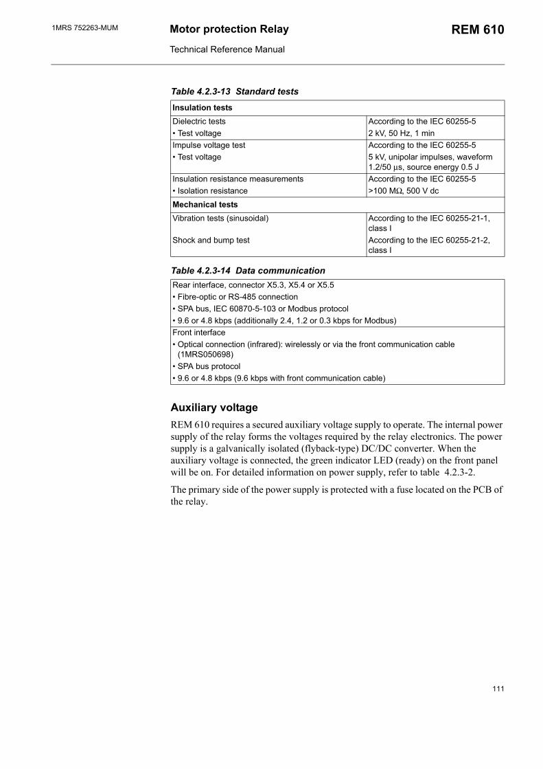
1MRS 752263-MUM Motor protection Relay
Technical Reference Manual
REM 610
Table 4.2.3-13 Standard tests
Insulation testsDielectric tests According to the IEC 60255-5 Test voltage 2 kV, 50 Hz, 1 minImpulse voltage test According to the IEC 60255-5 Test voltage 5 kV, unipolar impulses, waveform
1.2/50 µs, source energy 0.5 JInsulation resistance measurements According to the IEC 60255-5 Isolation resistance >100 MΩ, 500 V dc
Mechanical testsVibration tests (sinusoidal) According to the IEC 60255-21-1,
class IShock and bump test According to the IEC 60255-21-2,
class I
Table 4.2.3-14 Data communicationRear interface, connector X5.3, X5.4 or X5.5 Fibre-optic or RS-485 connection SPA bus, IEC 60870-5-103 or Modbus protocol 9.6 or 4.8 kbps (additionally 2.4, 1.2 or 0.3 kbps for Modbus)Front interface Optical connection (infrared): wirelessly or via the front communication cable
(1MRS050698) SPA bus protocol 9.6 or 4.8 kbps (9.6 kbps with front communication cable)
Auxiliary voltageREM 610 requires a secured auxiliary voltage supply to operate. The internal power supply of the relay forms the voltages required by the relay electronics. The power supply is a galvanically isolated (flyback-type) DC/DC converter. When the auxiliary voltage is connected, the green indicator LED (ready) on the front panel will be on. For detailed information on power supply, refer to table 4.2.3-2.
The primary side of the power supply is protected with a fuse located on the PCB of the relay.
111
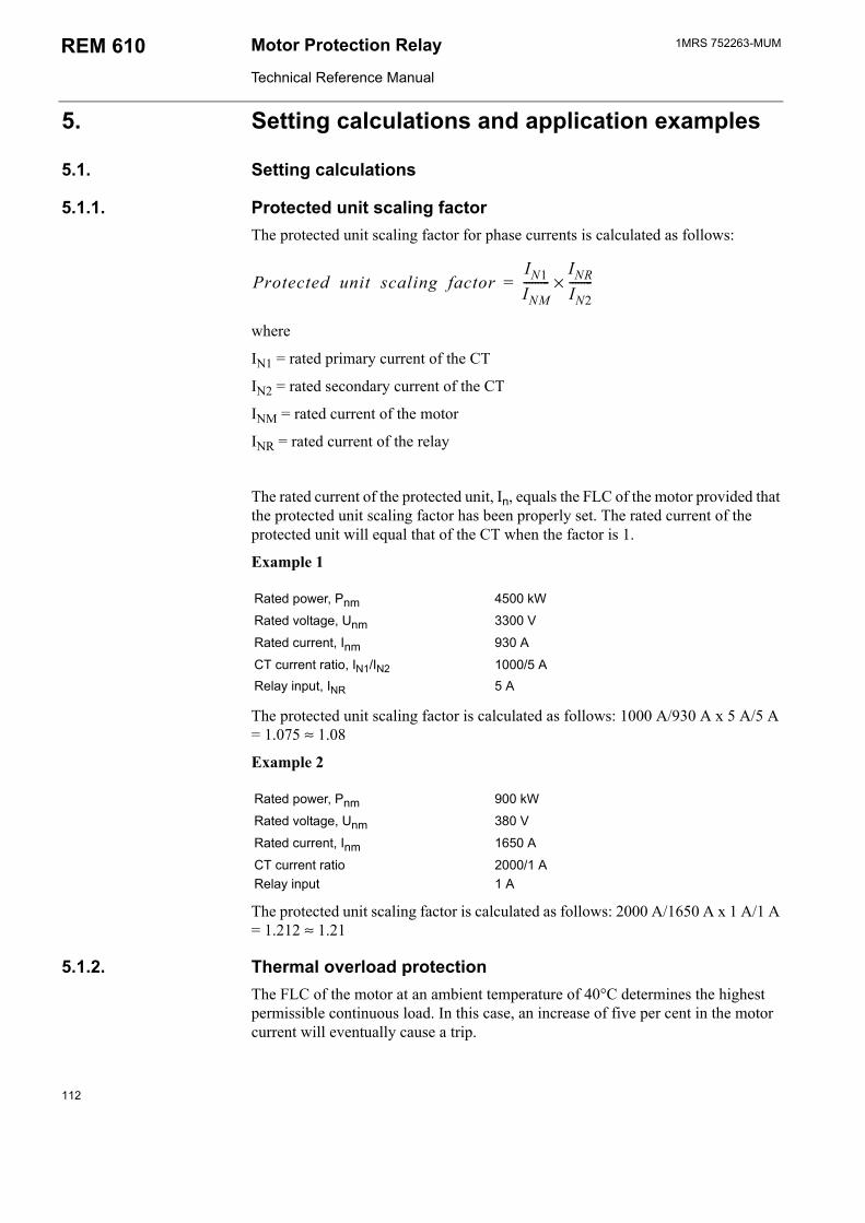
1MRS 752263-MUMMotor Protection Relay
Technical Reference Manual
REM 610
5. Setting calculations and application examples
5.1. Setting calculations
5.1.1. Protected unit scaling factorThe protected unit scaling factor for phase currents is calculated as follows:
Protected unit scaling factorIN1INM---------
INRIN2--------×=
where
IN1 = rated primary current of the CT
IN2 = rated secondary current of the CT
INM = rated current of the motor
INR = rated current of the relay
The rated current of the protected unit, In, equals the FLC of the motor provided that the protected unit scaling factor has been properly set. The rated current of the protected unit will equal that of the CT when the factor is 1.
Example 1
Rated power, Pnm 4500 kW
Rated voltage, Unm 3300 V
Rated current, Inm 930 A
CT current ratio, IN1/IN2 1000/5 ARelay input, INR 5 A
The protected unit scaling factor is calculated as follows: 1000 A/930 A x 5 A/5 A = 1.075 ≈ 1.08
Example 2
Rated power, Pnm 900 kW
Rated voltage, Unm 380 V
Rated current, Inm 1650 A
CT current ratio 2000/1 ARelay input 1 A
The protected unit scaling factor is calculated as follows: 2000 A/1650 A x 1 A/1 A = 1.212 ≈ 1.21
5.1.2. Thermal overload protectionThe FLC of the motor at an ambient temperature of 40°C determines the highest permissible continuous load. In this case, an increase of five per cent in the motor current will eventually cause a trip.
112
1MRS 752263-MUM Motor protection Relay
Technical Reference Manual
REM 610
Note!
If the settings of the thermal overload protection have been defined by means of the FLC of the motor instead of the internal FLC, they will be valid at an ambient temperature of 40°C.
For how the ambient temperature is used to determine the internal FLC, refer to section Thermal overload protection.
5.1.2.1. Selecting weighting factor pSetting p to 100 per cent creates a pure single time constant thermal protection for protecting cables, for instance. In this case, the allowed stall time will be only approximately ten per cent of the safe stall time, t6x, when no prior load; see Fig. 5.1.2.1.-1. At a set safe stall time of twenty seconds, the operate time when the prior load is 1 x FLC will be only two seconds, even though the motor can withstand a stall time of five seconds, for instance. To allow the use of the motors full capacity, a lower weighting factor should be used.
Normally, approximately half of the thermal capacity is used when a motor is running at full load. By setting p to 50 per cent, the thermal overload protection will take this into account.
In special cases where the thermal overload protection is required to follow the characteristics of the object to be protected more closely and the thermal capacity of the object is very well known, a value between 50 and 100 per cent may be required.
In applications where, for instance, three cold starts vs two hot starts are allowed, setting the weighting factor to 40 per cent has at times proved useful.
Note!
Setting the weighting factor to significantly below 50 per cent may overload the object to be protected as the thermal overload protection may allow too many hot starts or the thermal history of the motor has not sufficiently been taken into account.
113
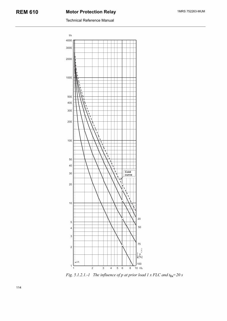
1MRS 752263-MUMMotor Protection Relay
Technical Reference Manual
REM 610
%E
/
,6
Fig. 5.1.2.1.-1 The influence of p at prior load 1 x FLC and t6x=20 s
114
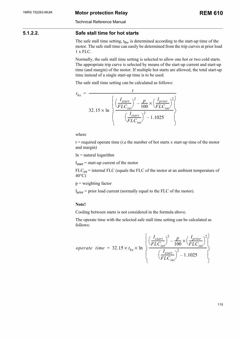
1MRS 752263-MUM Motor protection Relay
Technical Reference Manual
REM 610
5.1.2.2. Safe stall time for hot startsThe safe stall time setting, t6x, is determined according to the start-up time of the motor. The safe stall time can easily be determined from the trip curves at prior load 1 x FLC.
Normally, the safe stall time setting is selected to allow one hot or two cold starts. The appropriate trip curve is selected by means of the start-up current and start-up time (and margin) of the motor. If multiple hot starts are allowed, the total start-up time instead of a single start-up time is to be used.
The safe stall time setting can be calculated as follows:
t6xt
32.15
IstartFLCint-----------------
2 p100---------
IpriorFLCint-----------------
2×
IstartFLCint-----------------
21.1025
------------------------------------------------------------------------
ln×
------------------------------------------------------------------------------------------------------------=
where
t = required operate time (i.e the number of hot starts x start-up time of the motor and margin)
ln = natural logarithm
Istart = start-up current of the motor
FLCint = internal FLC (equals the FLC of the motor at an ambient temperature of 40°C)
p = weighting factor
Iprior = prior load current (normally equal to the FLC of the motor).
Note!
Cooling between starts is not considered in the formula above.
The operate time with the selected safe stall time setting can be calculated as follows:
operate time 32.15 t6x× ln×
IstartFLCint-----------------
2 p100---------
IpriorFLCint-----------------
2×
IstartFLCint-----------------
21.1025
------------------------------------------------------------------------
=
115
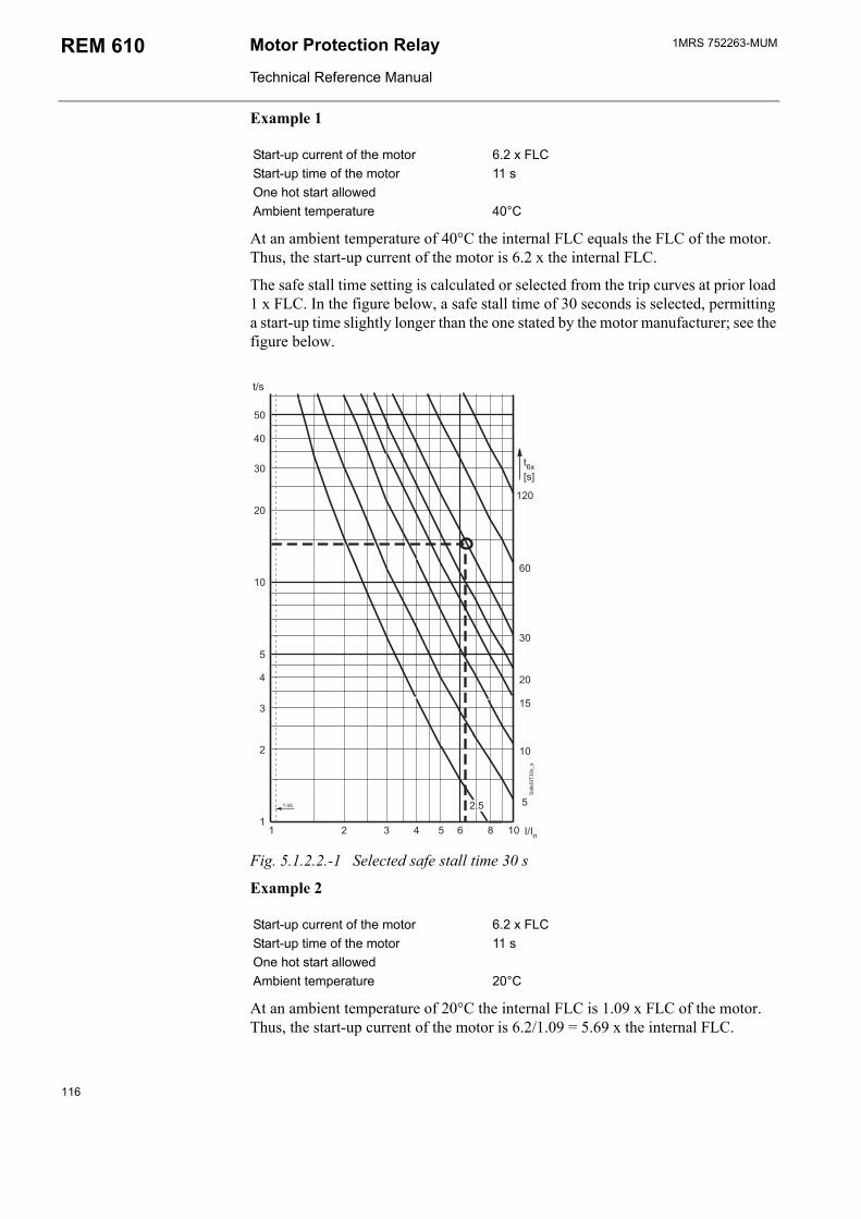
1MRS 752263-MUMMotor Protection Relay
Technical Reference Manual
REM 610
Example 1
Start-up current of the motor 6.2 x FLCStart-up time of the motor 11 sOne hot start allowedAmbient temperature 40°C
At an ambient temperature of 40°C the internal FLC equals the FLC of the motor. Thus, the start-up current of the motor is 6.2 x the internal FLC.
The safe stall time setting is calculated or selected from the trip curves at prior load 1 x FLC. In the figure below, a safe stall time of 30 seconds is selected, permitting a start-up time slightly longer than the one stated by the motor manufacturer; see the figure below.
#6#
:
Fig. 5.1.2.2.-1 Selected safe stall time 30 s
Example 2
Start-up current of the motor 6.2 x FLCStart-up time of the motor 11 sOne hot start allowedAmbient temperature 20°C
At an ambient temperature of 20°C the internal FLC is 1.09 x FLC of the motor. Thus, the start-up current of the motor is 6.2/1.09 = 5.69 x the internal FLC.
116
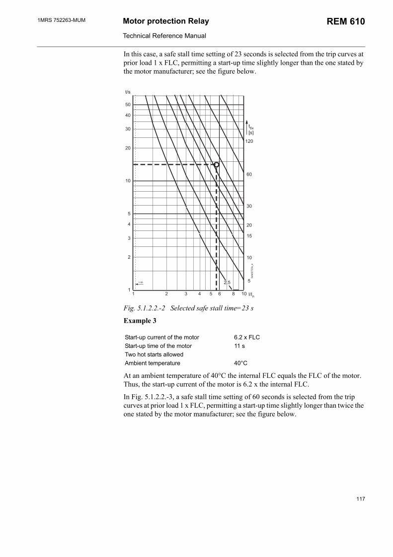
1MRS 752263-MUM Motor protection Relay
Technical Reference Manual
REM 610
In this case, a safe stall time setting of 23 seconds is selected from the trip curves at prior load 1 x FLC, permitting a start-up time slightly longer than the one stated by the motor manufacturer; see the figure below.
#6#
:
Fig. 5.1.2.2.-2 Selected safe stall time=23 s
Example 3
Start-up current of the motor 6.2 x FLCStart-up time of the motor 11 sTwo hot starts allowedAmbient temperature 40°C
At an ambient temperature of 40°C the internal FLC equals the FLC of the motor. Thus, the start-up current of the motor is 6.2 x the internal FLC.
In Fig. 5.1.2.2.-3, a safe stall time setting of 60 seconds is selected from the trip curves at prior load 1 x FLC, permitting a start-up time slightly longer than twice the one stated by the motor manufacturer; see the figure below.
117
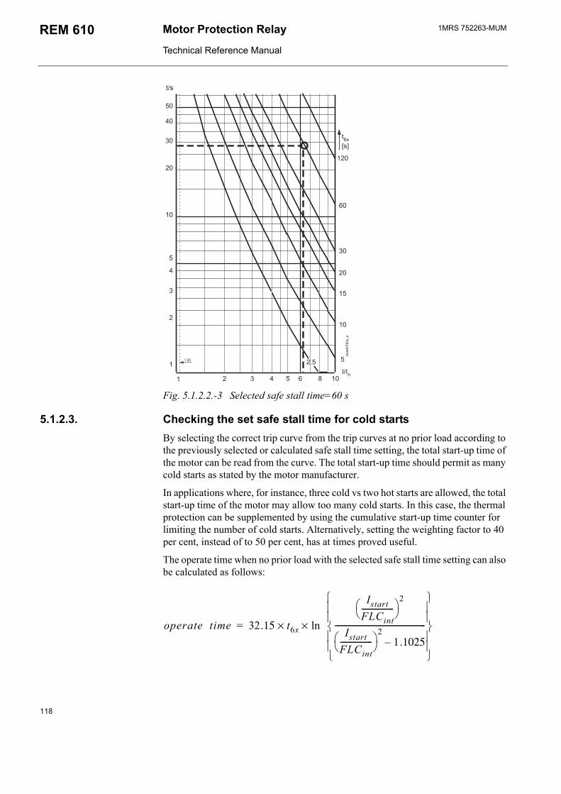
1MRS 752263-MUMMotor Protection Relay
Technical Reference Manual
REM 610
#6#
:
Fig. 5.1.2.2.-3 Selected safe stall time=60 s
5.1.2.3. Checking the set safe stall time for cold startsBy selecting the correct trip curve from the trip curves at no prior load according to the previously selected or calculated safe stall time setting, the total start-up time of the motor can be read from the curve. The total start-up time should permit as many cold starts as stated by the motor manufacturer.
In applications where, for instance, three cold vs two hot starts are allowed, the total start-up time of the motor may allow too many cold starts. In this case, the thermal protection can be supplemented by using the cumulative start-up time counter for limiting the number of cold starts. Alternatively, setting the weighting factor to 40 per cent, instead of to 50 per cent, has at times proved useful.
The operate time when no prior load with the selected safe stall time setting can also be calculated as follows:
operate time 32.15 t6x ln××
IstartFLCint-----------------
2
IstartFLCint-----------------
21.1025
------------------------------------------------
=
118
1MRS 752263-MUM Motor protection Relay
Technical Reference Manual
REM 610
5.1.2.4. Checking the set safe stall time for a single startIf the safe stall time of the motor is shorter than the operate time when no prior load, a single motor start up should instead be protected by the start-up supervision.
5.1.2.5. Restart inhibit level, θi
The restart inhibit level can be calculated as follows:
θi 100% start up time of the motoroperate time when no prior load------------------------------------------------------------------------------------------------ 100% margin+× =
For instance, if the start-up time of the motor is 11 seconds and the calculated operate time of the thermal protection stage when no prior load 25 seconds, one motor start up will use 11 s/25 s = 45% of the thermal capacity of the motor. Therefore, the restart inhibit level must be set to below 100% - 45% = 55%, e.g. to 50%.
5.1.2.6. Prior alarm level, θa
Tripping due to a beginning overload can be avoided by reducing the load of the motor at a prior alarm.
The prior alarm level can be set to a level, which will allow the use of the motors full thermal capacity without causing a trip due to long-time overload.
Generally, the prior alarm level is set to 8090 per cent of the trip level.
5.1.2.7. Time constant multiplier, Kc
The time constant multiplier, Kc, is the ratio of the cooling time (at motor standstill) and the heating time constant:
Kcτcoolingτheating-----------------=
Generally, the time constant multiplier of the motor is set to 4...6. However, when protecting non-rotating objects, e.g. feeder cables or transformers, for instance, the time constant multiplier is generally set to one.
5.1.3. Start-up supervisionStart-up supervision is based on thermal stress calculation by default but can also be set to be based on definite-time overcurrent protection, especially in other than motor applications.
5.1.3.1. Start-up supervision based on thermal stress calculationThe start-up current, Is>, is set to equal the start-up current of the motor and the start-up time, ts>, to approximately ten per cent above the start-up time of the motor in order to leave a safety margin for operation.
119
1MRS 752263-MUMMotor Protection Relay
Technical Reference Manual
REM 610
For instance, if the start-up current of the motor is 6.2 x FLC and the start-up time 11 seconds, Is> = 6.2 and ts> = 11 s x 1.1 = 12 s.
5.1.3.2. Checking the need for speed switchWhen protecting motors of ExE-type, for instance, the safe stall time may be shorter than the start-up time of the motor, which is why a speed switch on the motor shaft is required to give information on whether the motor is accelerating during motor start up. In this case, the start-up time is set to slightly below the safe stall time.
The speed switch should be open at standstill and closed during acceleration. When the input is activated, stage Is
2 x ts/Is> will be blocked. If the motor does not start to accelerate, stage Is
2 x ts will trip when the reference value, Is2 x ts, is exceeded. If
start-up supervision is based on overcurrent protection, stage Is> will trip on expiration of the set operate time
However, if the safe stall time is longer than the start-up time of the motor when no prior load, a speed switch will not be required.
5.1.4. Cumulative start-up time counterThe cumulative start-up time counter functions as backup to the thermal overload protection and prevents too frequent motor start ups, i.e. ensures that the recommendations from the manufacturer are followed.
There are two values to set: the restart inhibit value in seconds, Σtsi, and the countdown rate of the start-up time counter, ∆Σts/∆t.
The restart inhibit value is calculated as follows:
Σtsi n 1( ) t margin+×=
where
n = allowed number of motor start ups
t = start-up time of the motor (in seconds)
margin = safety margin (~10... 20%)
The countdown rate is calculated as follows:
∆Σtst
treset-----------=
where
t = start-up time of the motor (in seconds)
treset = time during which the maximum number of motor start ups stated by the manufacturer can be made (in hours)
If the motor manufacturer has recommended a maximum of three start ups in four hours and a start-up time of 60 seconds/start up, the restart inhibit will be activated when the third motor start up has been initiated, thus preventing a fourth motor start up. Consequently, the restart inhibit value is to be set to 130 seconds.
120
1MRS 752263-MUM Motor protection Relay
Technical Reference Manual
REM 610
A maximum of three motor start ups in four hours means that the registers value should reach the set restart inhibit value four hours later to allow a new motor start up. Consequently, the registers value should decrease by 60 seconds in four hours, i.e. ∆Σts/∆t = 60 s/4 h = 15 s/h.
5.1.5. Short-circuit protectionIt is recommended that the set start value of stage I>> is set to be automatically doubled during motor start up. Consequently, a start value lower than the start-up current of the motor can be selected.
A start value of 70%...90% x the start-up current of the motor is normally selected. This low a set start value together with a suitable set operate time will enable tripping of the high-set overcurrent stage if overcurrent due to a locked rotor, for instance, is detected while the motor is running.
Generally, a set start value as low as 75% of the start-up current of the motor has proved useful, but if the inrush current causes tripping during motor start up, a higher set start value will be required.
5.1.6. Unbalance and phase reversal protectionThe start value of the unbalance stage, I2>, is the NPS current which the motor can continuously withstand without being damaged. The time constant, K2, equals the motor constant, I2
2 x t, i.e. it determines the rotors ability to withstand heating caused by the NPS current.
The unbalance and the phase reversal protection stage can be separately selected or set out of operation. The phase reversal protection should be set out of operation in applications where the motor rotates in the opposite direction.
5.1.6.1. Selecting the start value for stage I2>The start value of stage I2> is selected as stated by the motor manufacturer. If the maximum allowed NPS voltage and not the current is stated, the NPS current will be approximately the same as the product of the NPS voltage and the ratio of the start-up current and the FLC of the motor.
For instance, if the start-up current of the motor is 6 x FLC and the maximum allowed NPS voltage four per cent, the estimated NPS current will be 6 x 4% = 24%. Thus, I2> will be 0.24 x In.
5.1.6.2. Selecting the time constant, K2
The time constant can be estimated as follows:
K2175
Istart( )2------------------=
where
Istart = start-up current of the motor x FLC
For instance, if the start-up current of the motor is 5 x FLC, the estimated time constant will be 175/52 = 7.
121
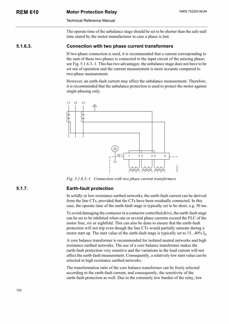
1MRS 752263-MUMMotor Protection Relay
Technical Reference Manual
REM 610
The operate time of the unbalance stage should be set to be shorter than the safe stall time stated by the motor manufacturer in case a phase is lost.
5.1.6.3. Connection with two phase current transformersIf two-phase connection is used, it is recommended that a current corresponding to the sum of these two phases is connected to the input circuit of the missing phase; see Fig. 5.1.6.3.-1. This has two advantages: the unbalance stage does not have to be set out of operation and the current measurement is more accurate compared to two-phase measurement.
However, an earth-fault current may affect the unbalance measurement. Therefore, it is recommended that the unbalance protection is used to protect the motor against single-phasing only.
( ( (
-+#:/0
Fig. 5.1.6.3.-1 Connection with two phase current transformers
5.1.7. Earth-fault protectionIn solidly or low-resistance earthed networks, the earth-fault current can be derived from the line CTs, provided that the CTs have been residually connected. In this case, the operate time of the earth-fault stage is typically set to be short, e.g. 50 ms.
To avoid damaging the contactor in a contactor controlled drive, the earth-fault stage can be set to be inhibited when one or several phase currents exceed the FLC of the motor four, six or eightfold. This can also be done to ensure that the earth-fault protection will not trip even though the line CTs would partially saturate during a motor start up. The start value of the earth-fault stage is typically set to 15...40% In.
A core balance transformer is recommended for isolated neutral networks and high resistance earthed networks. The use of a core balance transformer makes the earth-fault protection very sensitive and the variations in the load current will not affect the earth-fault measurement. Consequently, a relatively low start value can be selected in high resistance earthed networks.
The transformation ratio of the core balance transformer can be freely selected according to the earth-fault current, and consequently, the sensitivity of the earth-fault protection as well. Due to the extremely low burden of the relay, low
122
1MRS 752263-MUM Motor protection Relay
Technical Reference Manual
REM 610
transformation ratios may be used in cable current transformers, in KOLMA type transformers even as low as 10/1 A. However, a transformation ratio of at least 50/1 A or 100/1 A is recommended.
The start value of the earth-fault stage is typically selected to be 5...30% In of the fully developed earth-fault current and the operate time to be 0.5...2 seconds.
If a residual connection is preferred, the start value and operate time must be set slightly higher in order to avoid possible stability problems due to unbalance in the main transformers, as the unbalance will cause virtual earth-fault currents during high phase current conditions. Also, an external stabilizing resistor can be used to compensate too weak main transformers, thus preventing them from causing earth-fault currents.
5.1.7.1. Stabilizing virtual earth-fault currentsAn apparent earth-fault current caused by the difference between the phase current transformers connected in parallel may cause nuisance trippings of the earth-fault stage, especially during an overload. This can be avoided by using a stabilizing resistor in the earth-fault current circuit. The continuous power withstand of the resistor can be 30 W, for instance. The resistance value can be, for instance, 100 Ω when the 1 A input is used and 10 Ω when the 5 A input is used. The value of the knee-point voltage must be checked and should be >2 x Ustab. The stabilizing resistor will also slightly reduce the earth-fault sensitivity.
5.1.7.2. Increasing the sensitivity of the earth-fault protectionThe sensitivity of the earth-fault protection can be increased by using a relay provided with a 1 A input instead of one with a 5 A input. This is possible in a solidly earthed network as well, because the thermal withstand capability of the current input is normally high enough.
5.1.8. Circuit-breaker failure protectionThe operate time of the CBFP should be set to be longer than the circuit-breaker opening time + the resetting time of the protection stage with the longest resetting time, with the exception of the thermal, temperature and phase reversal protection stages and the external trip.
5.1.9. Temperature protection (optional)Tripping due to a beginning thermal overload can be avoided by reducing the load of the motor at an alarm of stage ThA>/ThB>.
123
1MRS 752263-MUMMotor Protection Relay
Technical Reference Manual
REM 610
5.2. Application examples
5.2.1. Protecting a circuit-breaker controlled motorData of the squirrel cage motor stated by the manufacturer:
Rated power, Pnm 4500 kW
Rated voltage, Unm 3300 V
Rated current, Inm 930 A
Start-up current of the motor 6.2 x FLCStart-up time of the motor 11 sSafe stall time 19 sAmbient temperature 40°CCT current ratio 1000/5 A (relay input = 5 A)
Setting calculationsThe protected unit scaling factor is calculated as follows:
1000A930A---------------- 5A
5A-------× 1.075 1.08≈=
For a direct-on-line started motor, p = 50%.
At an ambient temperature of 40°C the internal FLC equals the FLC of the motor. Thus the start-up current of the motor is 6.2 x the internal FLC.
The safe stall time setting, t6x, is calculated or selected from the trip curves at prior load 1 x FLC. A safe stall time setting of 30 seconds is selected, permitting a start-up time slightly longer than the one stated by the motor manufacturer.
By selecting the correct trip curve from the trip curves at no prior load according to the previously selected or calculated safe stall time setting, the total start-up time of the motor can be read from the curve. In this case, the thermal protection stage will trip in approximately 28 seconds, which will allow two cold starts.
However, as the operate time when no prior load is longer than the safe stall time of nineteen seconds, single motor start ups should instead be protected by the start-up supervision. The start-up current, Is>, is set to equal the start-up current of the motor and the start-up time, ts>, to approximately ten per cent above the start-up time of the motor in order to leave a safety margin for operation. Thus ts> is set to 1 s x 1.1 ≈ 12 s.
As the safe stall time is longer than the start-up time of the motor, no speed switch will be required.
As one motor start up uses 11 s/28 s ≈ 39% of the thermal capacity of the motor, the restart inhibit level, θi>, should be set to below 61 per cent, e.g. to 55 per cent.
The prior alarm level, θa>, is set to 80...90 per cent of the trip level.
The time constant multiplier, Kc, is set to 4.
124
1MRS 752263-MUM Motor protection Relay
Technical Reference Manual
REM 610
If the start value of stage I>> is set to be doubled during motor start up (SGF3/8=1), the start value should be set below the start-up current of the motor, i.e to 75...90% x the start-up current of the motor: I>> = 0.75 x 6.2 ≈ 4.65.
5.2.2. Protecting a motor at an ambient temperature other than 40°CData of the squirrel cage motor stated by the manufacturer:
Rated power, Pnm 4500 kW
Rated voltage, Unm 3300 V
Rated current, Inm 930 A
Start-up current of the motor 6.2 x FLCStart-up time of the motor 11 sSafe stall time 19 sAmbient temperature 20...70°CCT current ratio 1000/5 A (relay input = 5 A)
Setting calculationsThe protected unit scaling factor is calculated as follows:
1000A930A---------------- 5A
5A-------× 1.075 1.08≈=
For a direct-on-line started motor, p = 50%.
At an ambient temperature of 40°C the internal FLC is 1.0 x FLC of the motor. Thus, the start-up current of the motor is 6.2 x the internal FLC. A safe stall time of 30 seconds is selected as in the previous application example.
If the ambient temperature is lower than 40°C, the motor can be run at a slight overload in relation to the specified maximum load at 40°C. If the ambient temperature is higher than 40°C, the continuous load must be lower than the specified maximum load at 40°C.
At an ambient temperature of 20°C the internal FLC is 1.09 x FLC of the motor. Thus, the start-up current of the motor is 6.2/1.09 = 5.69 x the internal FLC. If a safe stall time setting of 30 seconds is selected, the relay will allow two hot starts instead of one. If this is unacceptable, however, and only one hot start is to be allowed, a safe stall time setting of 23 seconds is to be selected instead.
At an ambient temperature of 65°C the internal FLC is 0.75 x the FLC of the motor. Thus, the start-up current of the motor is 6.2/0.75 = 8.27 x the internal FLC. If a safe stall time setting of 30 seconds and a prior load of 0.75 x the FLC of the motor are selected, the relay will not allow a hot start until the motor has been at standstill for several minutes. However, if a hot start is to be allowed, a safe stall time setting of approximately 50 seconds is to be selected instead.
All other settings are as in the previous application example.
125
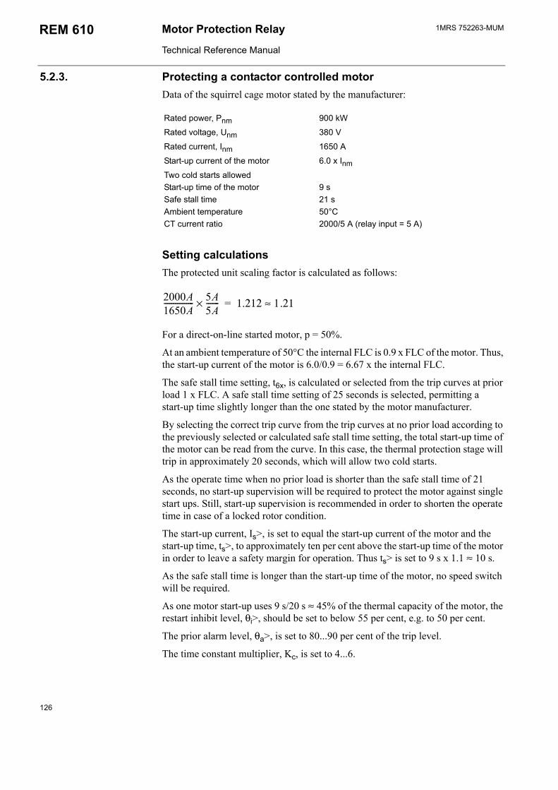
1MRS 752263-MUMMotor Protection Relay
Technical Reference Manual
REM 610
5.2.3. Protecting a contactor controlled motorData of the squirrel cage motor stated by the manufacturer:
Rated power, Pnm 900 kW
Rated voltage, Unm 380 V
Rated current, Inm 1650 A
Start-up current of the motor 6.0 x InmTwo cold starts allowedStart-up time of the motor 9 sSafe stall time 21 sAmbient temperature 50°CCT current ratio 2000/5 A (relay input = 5 A)
Setting calculationsThe protected unit scaling factor is calculated as follows:
2000A1650A---------------- 5A
5A-------× 1.212 1.21≈=
For a direct-on-line started motor, p = 50%.
At an ambient temperature of 50°C the internal FLC is 0.9 x FLC of the motor. Thus, the start-up current of the motor is 6.0/0.9 = 6.67 x the internal FLC.
The safe stall time setting, t6x, is calculated or selected from the trip curves at prior load 1 x FLC. A safe stall time setting of 25 seconds is selected, permitting a start-up time slightly longer than the one stated by the motor manufacturer.
By selecting the correct trip curve from the trip curves at no prior load according to the previously selected or calculated safe stall time setting, the total start-up time of the motor can be read from the curve. In this case, the thermal protection stage will trip in approximately 20 seconds, which will allow two cold starts.
As the operate time when no prior load is shorter than the safe stall time of 21 seconds, no start-up supervision will be required to protect the motor against single start ups. Still, start-up supervision is recommended in order to shorten the operate time in case of a locked rotor condition.
The start-up current, Is>, is set to equal the start-up current of the motor and the start-up time, ts>, to approximately ten per cent above the start-up time of the motor in order to leave a safety margin for operation. Thus ts> is set to 9 s x 1.1 ≈ 10 s.
As the safe stall time is longer than the start-up time of the motor, no speed switch will be required.
As one motor start-up uses 9 s/20 s ≈ 45% of the thermal capacity of the motor, the restart inhibit level, θi>, should be set to below 55 per cent, e.g. to 50 per cent.
The prior alarm level, θa>, is set to 80...90 per cent of the trip level.
The time constant multiplier, Kc, is set to 4...6.
126
1MRS 752263-MUM Motor protection Relay
Technical Reference Manual
REM 610
The high-set overcurrent stage should be set out of operation to prevent the contactor in a contactor controlled drive from operating at too high phase currents. In addition, to avoid damaging the contactor, the earth-fault stage should be set to be inhibited when one or several phase currents exceed the FLC of the motor sixfold (SGF4/1 = 1, SGF4/2 = 0). During high phase current conditions the protection will be based on the backup fuses.
5.2.4. Protecting non-rotating objectsIn other than motor applications, start-up supervision is usually set to be based on definite-time overcurrent protection (SGF3/6=1) or on thermal stress calculation (start criterion IL>Is). If start-up supervision is set to be based on thermal stress calculation (SGF3/6=0) and stage Is
2 x ts is set to start when one or several phase currents exceed the set start value (SGF3/7=1), the tripping of stage Is
2 x ts will be similar to that at the IDMT characteristic extremely inverse.
If a core balance transformer is used for measuring the earth-fault current, refer to section 5.1.7. Earth-fault protection.
When protecting objects without hot spot tendencies, weighting factor p is set to 100 per cent. When setting t6x, the expression τ = 32.15 x t6x can be used.
Usually, the time constant multiplier, Kc, is set to 1.
5.2.5. Earth-fault protection in an isolated or a compensated networkData of the motor stated by the manufacturer:
Network earth-fault current at fullydeveloped earth-fault
10 A isolated network
Required earth-fault sensitivity 20% (=2A)
Due to the high sensitivity required, a residual connection cannot be used, but instead, a core balance transformer with a CT ratio of 100/1.
The start value of stage I0> is calculated as follows:
20% 10A 1A100A-------------×× 2% 1A×=
Thus, I0> = 2% and the 1A input is used.
5.2.6. Earth-fault protection in a solidly earthed networkData of the motor stated by the manufacturer:
Rated current, Inm 1650 A
CT current ratio 2000/5 A (relay input = 5 A)Required earth-fault sensitivity 20% Inm
127

1MRS 752263-MUMMotor Protection Relay
Technical Reference Manual
REM 610
The start value of stage I0> is calculated as follows:
20% 1650A 5A2000A----------------×× 16% 5A×=
Thus, I0> = 16% and the 5A input is used.
The operate time of the earth-fault stage is set to 50 ms when the network is solidly earthed.
If the drive is contactor controlled, refer to section Protecting a contactor controlled motor.
128
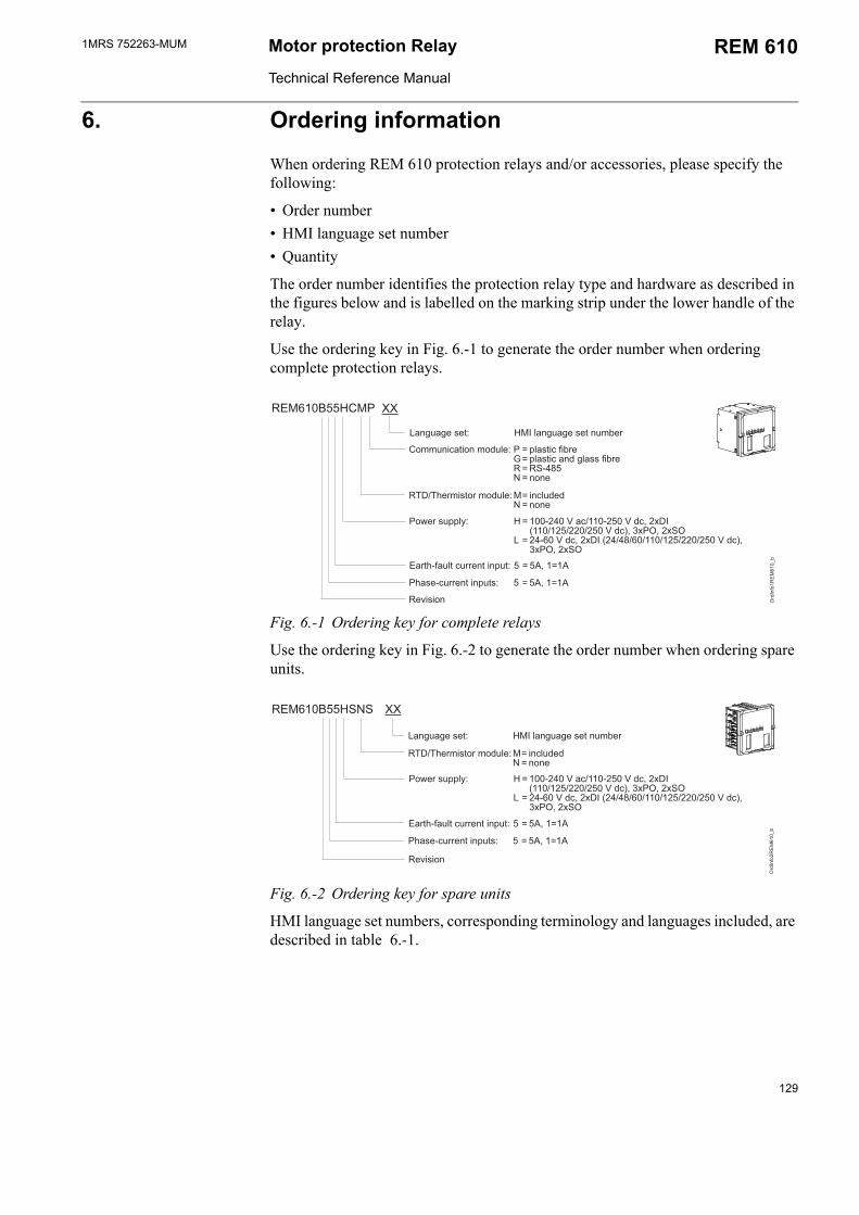
1MRS 752263-MUM Motor protection Relay
Technical Reference Manual
REM 610
6. Ordering information
When ordering REM 610 protection relays and/or accessories, please specify the following:
Order number HMI language set number Quantity
The order number identifies the protection relay type and hardware as described in the figures below and is labelled on the marking strip under the lower handle of the relay.
Use the ordering key in Fig. 6.-1 to generate the order number when ordering complete protection relays.
*+,66%*2
<;',
*+,
5
//
'44:'4'<) 2 = ($:;5)= ($:<$$;5) = &# -6= ')
>?)4$'4'<)*= :<)<= ')
2'@)$((A % = ,# 3:>,,#63<:B18,,>,6>>63<:9B12B1&
= #+3<:B18 > ->+>,,>,6>>63<:9B 12B1&
?#;:)( 6 = 6B,=,
2?$)#:)($ 6 = 6B,=,
)C$'
)$) %*)$)45)
Fig. 6.-1 Ordering key for complete relays
Use the ordering key in Fig. 6.-2 to generate the order number when ordering spare units.
*+,66%&&
<;'
*+,5
//
>?)4$'4'<)*= :<)<= ')
2'@)$((A % = ,# 3:>,,#63<:B18,,>,6>>63<:9B12B1&
= #+3<:B18 > ->+>,,>,6>>63<:9B 12B1&
?#;:)( 6 = 6B,=,
2?$)#:)($ 6 = 6B,=,
)C$'
)$) %*)$)45)
Fig. 6.-2 Ordering key for spare units
HMI language set numbers, corresponding terminology and languages included, are described in table 6.-1.
129
1MRS 752263-MUMMotor Protection Relay
Technical Reference Manual
REM 610
Table 6.-1 HMI language set numbers
Language set number Terminology Languages01 IEC English, Svenska, Suomi02 IEC English, Deutsch, Francais, Italiano,
Español11 ANSI English (US), Español, Portuguese
The following accessories are available:
Item Order numberSemi-flush mounting kit 1MRS050696
Inclined (/ 25o) semi-flush mounting kit 1MRS050831
Wall mounting kit 1MRS05069719 Rack mounting kit, side-by-side 1MRS05069519" Rack mounting kit, single relay 1MRS05069419" Rack mounting kit for single relay and RTXP18 1MRS050783Front communication cable 1MRS050698
130
1MRS 752263-MUM Motor protection Relay
Technical Reference Manual
REM 610
7. Revision history of REM 610
7.1. Revision identificationThe different revisions of REM 610 may include functional additions and changes to the product.
Product Revision ReleaseREM 610 A Q4/2003
B Q1/2005
7.2. Changes and additions to the earlier released revision AGeneral The product can be ordered with different language sets using IEC or ANSI
terminology Current condition added for external triggering of CBFP Time synchronization via a digital input added Warning signal from TCS can be routed to SO2 Reading of event records via ModbusHardware Low voltage power supply option added Combined glass and plastic communication option added
131
1MRS 752263-MUMMotor Protection Relay
Technical Reference Manual
REM 610
8. References
Other available manuals:
Operators Manual, 1MRS 752264-MUM Installation Manual, 1MRS 752265-MUM
132

1MRS 752263-MUM Motor protection Relay
Technical Reference Manual
REM 610
9. AbbreviationsANSI American National Standards Institute
ASCII American Standard Code for Information Interchange
CBFP Circuit-breaker failure protection
CD Change detect
CPU Central Processing Unit
CRC Cyclical Redundancy Check
CT Current transformer
DI Digital input
EMC Electromagnetic compatibility
FLC Full load current
FR Fault record
GI General interrogation
HMI Human-Machine Interface
HR Holding register
IDMT Inverse definite minimum time
IEC International Electrotechnical Commission
IEC_103 Standard IEC 60870-5-103
IR Input registers
IRF Internal relay fault
LCD Liquid Crystal Display
LED Light-emitting diode
LRC Longitudinal Redundancy Check
LSB Least significant bit
MSB Most significant bit
MV Medium Voltage
NC Normally closed
NO Normally open
NPS Negative-phase-sequence
PC Personal Computer
PCB Printed Circuit Board
PLC Programmable Logical Controller
PO1, PO2, PO3 Power outputs
REV Phase reversal
RMS Root Mean Square
RTD Resistive Temperature Detector
RTU Remote Terminal Unit
SGB Switchgroups for digital inputs
SGF Switchgroups for functions
SGL Switchgroups for programmable LEDs
SGR Switchgroups for output contacts
SO1, SO2 Signal outputs
133

1MRS 752263-MUMMotor Protection Relay
Technical Reference Manual
REM 610
TCR Temperature coefficient of resistance
TCS Trip-circuit supervision
UDR User-defined register
134
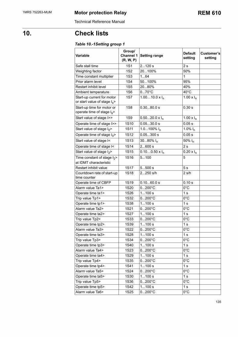
1MRS 752263-MUM Motor protection Relay
Technical Reference Manual
REM 610
10. Check lists Table 10.-1Setting group 1
VariableGroup/
Channel 1(R, W, P)
Setting range Default setting
Customers setting
Safe stall time 1S1 2...120 s 2 sWeighting factor 1S2 20...100% 50%Time constant multiplier 1S3 1...64 1Prior alarm level 1S4 50...100% 95%Restart inhibit level 1S5 20...80% 40%Ambient temperature 1S6 0...70°C 40°CStart-up current for motor or start value of stage Is>
1S7 1.0010.0 x In 1.00 x In
Start-up time for motor or operate time of stage Is>
1S8 0.30...80.0 s 0.30 s
Start value of stage I>> 1S9 0.50...20.0 x In 1.00 x InOperate time of stage I>> 1S10 0.05...30.0 s 0.05 sStart value of stage I0> 1S11 1.0...100% In 1.0% InOperate time of stage I0> 1S12 0.05...300 s 0.05 sStart value of stage I< 1S13 30...80% In 50% InOperate time of stage I< 1S14 2...600 s 2 sStart value of stage I2> 1S15 0.100.50 x In 0.20 x InTime constant of stage I2> at IDMT characteristic
1S16 5...100 5
Restart inhibit value 1S17 5...500 s 5 sCountdown rate of start-up time counter
1S18 2...250 s/h 2 s/h
Operate time of CBFP 1S19 0.10...60.0 s 0.10 sAlarm value Ta1> 1S20 0...200°C 0°COperate time ta1> 1S26 1...100 s 1 sTrip value Tp1> 1S32 0...200°C 0°COperate time tp1> 1S38 1...100 s 1 sAlarm value Ta2> 1S21 0...200°C 0°COperate time ta2> 1S27 1...100 s 1 sTrip value Tp2> 1S33 0...200°C 0°COperate time tp2> 1S39 1...100 s 1 sAlarm value Ta3> 1S22 0...200°C 0°COperate time ta3> 1S28 1...100 s 1 sTrip value Tp3> 1S34 0...200°C 0°COperate time tp3> 1S40 1...100 s 1 sAlarm value Ta4> 1S23 0...200°C 0°COperate time ta4> 1S29 1...100 s 1 sTrip value Tp4> 1S35 0...200°C 0°COperate time tp4> 1S41 1...100 s 1 sAlarm value Ta5> 1S24 0...200°C 0°COperate time ta5> 1S30 1...100 s 1 sTrip value Tp5> 1S36 0...200°C 0°COperate time tp5> 1S42 1...100 s 1 sAlarm value Ta6> 1S25 0...200°C 0°C
135
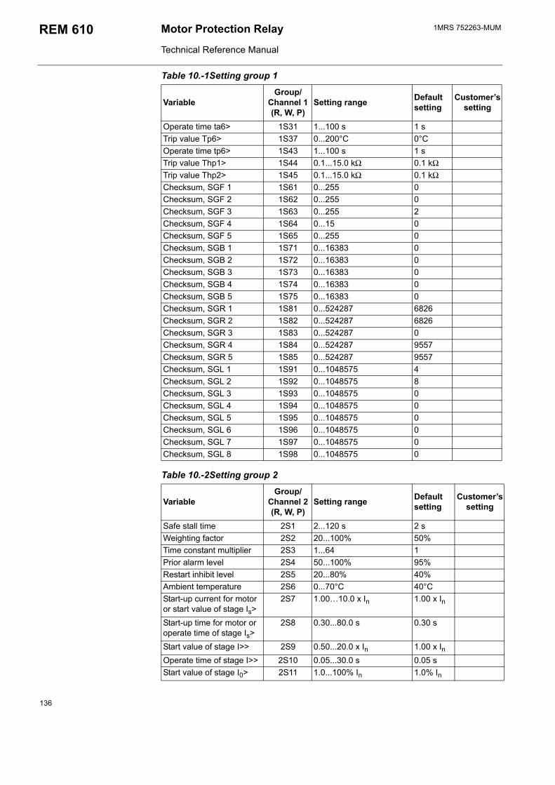
1MRS 752263-MUMMotor Protection Relay
Technical Reference Manual
REM 610
Operate time ta6> 1S31 1...100 s 1 sTrip value Tp6> 1S37 0...200°C 0°COperate time tp6> 1S43 1...100 s 1 sTrip value Thp1> 1S44 0.1...15.0 kΩ 0.1 kΩTrip value Thp2> 1S45 0.1...15.0 kΩ 0.1 kΩChecksum, SGF 1 1S61 0...255 0Checksum, SGF 2 1S62 0...255 0Checksum, SGF 3 1S63 0...255 2Checksum, SGF 4 1S64 0...15 0Checksum, SGF 5 1S65 0...255 0Checksum, SGB 1 1S71 0...16383 0Checksum, SGB 2 1S72 0...16383 0Checksum, SGB 3 1S73 0...16383 0Checksum, SGB 4 1S74 0...16383 0Checksum, SGB 5 1S75 0...16383 0Checksum, SGR 1 1S81 0...524287 6826Checksum, SGR 2 1S82 0...524287 6826Checksum, SGR 3 1S83 0...524287 0Checksum, SGR 4 1S84 0...524287 9557Checksum, SGR 5 1S85 0...524287 9557Checksum, SGL 1 1S91 0...1048575 4Checksum, SGL 2 1S92 0...1048575 8Checksum, SGL 3 1S93 0...1048575 0Checksum, SGL 4 1S94 0...1048575 0Checksum, SGL 5 1S95 0...1048575 0Checksum, SGL 6 1S96 0...1048575 0Checksum, SGL 7 1S97 0...1048575 0Checksum, SGL 8 1S98 0...1048575 0
Table 10.-2Setting group 2
VariableGroup/
Channel 2(R, W, P)
Setting range Default setting
Customers setting
Safe stall time 2S1 2...120 s 2 sWeighting factor 2S2 20...100% 50%Time constant multiplier 2S3 1...64 1Prior alarm level 2S4 50...100% 95%Restart inhibit level 2S5 20...80% 40%Ambient temperature 2S6 0...70°C 40°CStart-up current for motor or start value of stage Is>
2S7 1.0010.0 x In 1.00 x In
Start-up time for motor or operate time of stage Is>
2S8 0.30...80.0 s 0.30 s
Start value of stage I>> 2S9 0.50...20.0 x In 1.00 x InOperate time of stage I>> 2S10 0.05...30.0 s 0.05 sStart value of stage I0> 2S11 1.0...100% In 1.0% In
Table 10.-1Setting group 1
VariableGroup/
Channel 1(R, W, P)
Setting range Default setting
Customers setting
136
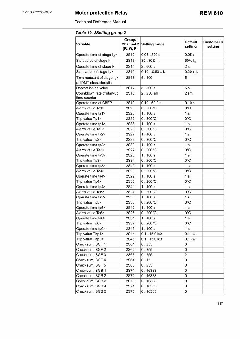
1MRS 752263-MUM Motor protection Relay
Technical Reference Manual
REM 610
Operate time of stage I0> 2S12 0.05...300 s 0.05 sStart value of stage I< 2S13 30...80% In 50% InOperate time of stage I< 2S14 2...600 s 2 sStart value of stage I2> 2S15 0.100.50 x In 0.20 x InTime constant of stage I2> at IDMT characteristic
2S16 5...100 5
Restart inhibit value 2S17 5...500 s 5 sCountdown rate of start-up time counter
2S18 2...250 s/h 2 s/h
Operate time of CBFP 2S19 0.10...60.0 s 0.10 sAlarm value Ta1> 2S20 0...200°C 0°COperate time ta1> 2S26 1...100 s 1 sTrip value Tp1> 2S32 0...200°C 0°COperate time tp1> 2S38 1...100 s 1 sAlarm value Ta2> 2S21 0...200°C 0°COperate time ta2> 2S27 1...100 s 1 sTrip value Tp2> 2S33 0...200°C 0°COperate time tp2> 2S39 1...100 s 1 sAlarm value Ta3> 2S22 0...200°C 0°COperate time ta3> 2S28 1...100 s 1 sTrip value Tp3> 2S34 0...200°C 0°COperate time tp3> 2S40 1...100 s 1 sAlarm value Ta4> 2S23 0...200°C 0°COperate time ta4> 2S29 1...100 s 1 sTrip value Tp4> 2S35 0...200°C 0°COperate time tp4> 2S41 1...100 s 1 sAlarm value Ta5> 2S24 0...200°C 0°COperate time ta5> 2S30 1...100 s 1 sTrip value Tp5> 2S36 0...200°C 0°COperate time tp5> 2S42 1...100 s 1 sAlarm value Ta6> 2S25 0...200°C 0°COperate time ta6> 2S31 1...100 s 1 sTrip value Tp6> 2S37 0...200°C 0°COperate time tp6> 2S43 1...100 s 1 sTrip value Thp1> 2S44 0.1...15.0 kΩ 0.1 kΩTrip value Thp2> 2S45 0.1...15.0 kΩ 0.1 kΩChecksum, SGF 1 2S61 0...255 0Checksum, SGF 2 2S62 0...255 0Checksum, SGF 3 2S63 0...255 2Checksum, SGF 4 2S64 0...15 0Checksum, SGF 5 2S65 0...255 0Checksum, SGB 1 2S71 0...16383 0Checksum, SGB 2 2S72 0...16383 0Checksum, SGB 3 2S73 0...16383 0Checksum, SGB 4 2S74 0...16383 0Checksum, SGB 5 2S75 0...16383 0
Table 10.-2Setting group 2
VariableGroup/
Channel 2(R, W, P)
Setting range Default setting
Customers setting
137
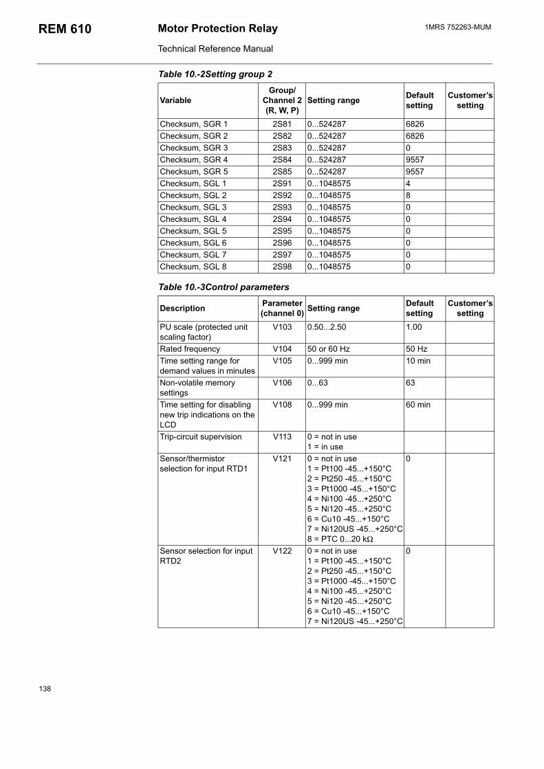
1MRS 752263-MUMMotor Protection Relay
Technical Reference Manual
REM 610
Checksum, SGR 1 2S81 0...524287 6826Checksum, SGR 2 2S82 0...524287 6826Checksum, SGR 3 2S83 0...524287 0Checksum, SGR 4 2S84 0...524287 9557Checksum, SGR 5 2S85 0...524287 9557Checksum, SGL 1 2S91 0...1048575 4Checksum, SGL 2 2S92 0...1048575 8Checksum, SGL 3 2S93 0...1048575 0Checksum, SGL 4 2S94 0...1048575 0Checksum, SGL 5 2S95 0...1048575 0Checksum, SGL 6 2S96 0...1048575 0Checksum, SGL 7 2S97 0...1048575 0Checksum, SGL 8 2S98 0...1048575 0
Table 10.-3Control parameters
Description Parameter(channel 0) Setting range Default
settingCustomers
settingPU scale (protected unit scaling factor)
V103 0.50...2.50 1.00
Rated frequency V104 50 or 60 Hz 50 HzTime setting range for demand values in minutes
V105 0...999 min 10 min
Non-volatile memory settings
V106 0...63 63
Time setting for disabling new trip indications on the LCD
V108 0...999 min 60 min
Trip-circuit supervision V113 0 = not in use1 = in use
Sensor/thermistor selection for input RTD1
V121 0 = not in use1 = Pt100 -45...+150°C2 = Pt250 -45...+150°C3 = Pt1000 -45...+150°C4 = Ni100 -45...+250°C5 = Ni120 -45...+250°C6 = Cu10 -45...+150°C7 = Ni120US -45...+250°C8 = PTC 0...20 kΩ
0
Sensor selection for input RTD2
V122 0 = not in use1 = Pt100 -45...+150°C2 = Pt250 -45...+150°C3 = Pt1000 -45...+150°C4 = Ni100 -45...+250°C5 = Ni120 -45...+250°C6 = Cu10 -45...+150°C7 = Ni120US -45...+250°C
0
Table 10.-2Setting group 2
VariableGroup/
Channel 2(R, W, P)
Setting range Default setting
Customers setting
138
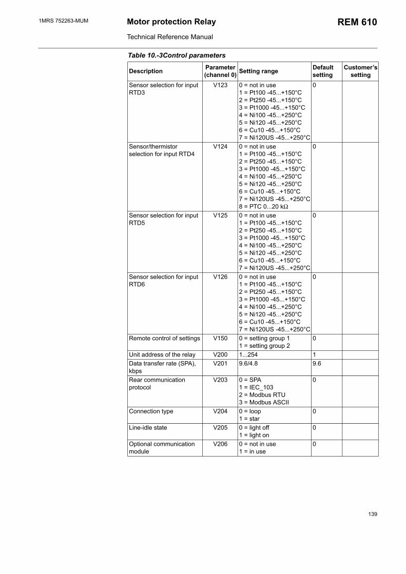
1MRS 752263-MUM Motor protection Relay
Technical Reference Manual
REM 610
Sensor selection for input RTD3
V123 0 = not in use1 = Pt100 -45...+150°C2 = Pt250 -45...+150°C3 = Pt1000 -45...+150°C4 = Ni100 -45...+250°C5 = Ni120 -45...+250°C6 = Cu10 -45...+150°C7 = Ni120US -45...+250°C
0
Sensor/thermistor selection for input RTD4
V124 0 = not in use1 = Pt100 -45...+150°C2 = Pt250 -45...+150°C3 = Pt1000 -45...+150°C4 = Ni100 -45...+250°C5 = Ni120 -45...+250°C6 = Cu10 -45...+150°C7 = Ni120US -45...+250°C8 = PTC 0...20 kΩ
0
Sensor selection for input RTD5
V125 0 = not in use1 = Pt100 -45...+150°C2 = Pt250 -45...+150°C3 = Pt1000 -45...+150°C4 = Ni100 -45...+250°C5 = Ni120 -45...+250°C6 = Cu10 -45...+150°C7 = Ni120US -45...+250°C
0
Sensor selection for input RTD6
V126 0 = not in use1 = Pt100 -45...+150°C2 = Pt250 -45...+150°C3 = Pt1000 -45...+150°C4 = Ni100 -45...+250°C5 = Ni120 -45...+250°C6 = Cu10 -45...+150°C7 = Ni120US -45...+250°C
0
Remote control of settings V150 0 = setting group 11 = setting group 2
0
Unit address of the relay V200 1...254 1Data transfer rate (SPA), kbps
V201 9.6/4.8 9.6
Rear communication protocol
V203 0 = SPA1 = IEC_103 2 = Modbus RTU3 = Modbus ASCII
0
Connection type V204 0 = loop 1 = star
0
Line-idle state V205 0 = light off 1 = light on
0
Optional communication module
V206 0 = not in use1 = in use
0
Table 10.-3Control parameters
Description Parameter(channel 0) Setting range Default
settingCustomers
setting
139
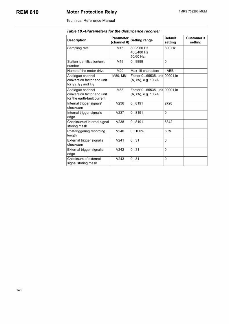
1MRS 752263-MUMMotor Protection Relay
Technical Reference Manual
REM 610
Table 10.-4Parameters for the disturbance recorder
Description Parameter(channel 0) Setting range Default
settingCustomers
settingSampling rate M15 800/960 Hz
400/480 Hz50/60 Hz
800 Hz
Station identification/unit number
M18 0...9999 0
Name of the motor drive M20 Max 16 characters - ABB -Analogue channel conversion factor and unit for IL1, IL2 and IL3
M80, M81 Factor 0...65535, unit (A, kA), e.g. 10,kA
00001,In
Analogue channel conversion factor and unit for the earth-fault current
M83 Factor 0...65535, unit (A, kA), e.g. 10,kA
00001,In
Internal trigger signals' checksum
V236 0...8191 2728
Internal trigger signal's edge
V237 0...8191 0
Checksum of internal signal storing mask
V238 0...8191 6842
Post-triggering recording length
V240 0...100% 50%
External trigger signal's checksum
V241 0...31 0
External trigger signal's edge
V242 0...31 0
Checksum of external signal storing mask
V243 0...31 0
140


ADP.FFTeFw
1MR
S 75
2263
-MU
M E
N 0
9.20
05
BB Oyistribution Automation O. Box 699 I-65101 Vaasa INLANDl. +358 10 22 11
ax. +358 10 224 1094ww.abb.com/substationautomation