ansi, rem 610 motor protection relay, operator's manual ... · motor protection relay...
TRANSCRIPT

Motor Protection RelayREM 610REM 610
Operator's Manual - ANSI version

3
Contents
Copyrights ................................................................................. 5
1. Introduction..............................................................71.1. This manual .............................................................. 71.2. Use of symbols ......................................................... 71.3. Intended audience ..................................................... 71.4. Product documentation ............................................... 81.5. Document conventions ............................................... 81.6. Document revisions.................................................... 9
2. Safety information................................................... 11
3. Product overview....................................................133.1. Use of the relay....................................................... 133.2. Features................................................................. 13
4. Operation ...............................................................154.1. HMI features ........................................................... 15
4.1.1. Front panel ................................................. 154.1.2. How to use the push buttons ......................... 154.1.3. Display....................................................... 16
4.1.3.1. Display test at power up ................. 164.1.3.2. Display modes .............................. 174.1.3.3. Display backlight ........................... 184.1.3.4. How to adjust the display contrast .... 18
4.1.4. Main menu ................................................. 184.1.5. Submenu.................................................... 194.1.6. HMI passwords ........................................... 194.1.7. SPA password............................................. 214.1.8. How to select language ................................ 214.1.9. How to set the real-time clock........................ 224.1.10. How to switch between front and rear
connection.................................................. 234.1.10.1. Target LED for front communication... 24
4.1.11. How to select the protocol for rearcommunication ............................................ 24
4.2. HMI operation levels ................................................ 254.2.1. User level ................................................... 25
4.2.1.1. Menu groups of the user level ......... 254.2.1.2. How to monitor measured values ..... 264.2.1.3. How to monitor recorded data ......... 284.2.1.4. INFO menu group.......................... 29
4.2.2. Technical level............................................. 304.2.2.1. Menu system of parameters ............ 304.2.2.2. How to change settings .................. 30
Motor Protection Relay
Operator's Manual - ANSI version
REM 610REM 6101MRS755538
Issued: 01.04.2005Version: B/31.01.2007

4.2.2.3. Configuration ................................ 344.2.2.4. How to acknowledge and reset
targets, output contacts andmemorized values ......................... 38
4.3. Protection relay targets ............................................. 384.3.1. Target LEDs................................................ 38
4.3.1.1. Green target LED .......................... 384.3.1.2. Yellow target LED.......................... 394.3.1.3. Red target LED............................. 394.3.1.4. Programmable target LEDs ............. 40
4.3.2. Target messages ......................................... 404.3.2.1. Operation target messages ............. 404.3.2.2. Disturbance recorder target ............. 424.3.2.3. Self-supervision............................. 43
4.4. Detachable plug-in unit ............................................. 464.4.1. Identifying the product .................................. 464.4.2. Detaching and installing the plug-in unit........... 474.4.3. Inserting and changing the battery .................. 49
5. Commissioning and maintenance.............................515.1. Commissioning instructions ....................................... 515.2. Maintenance instructions........................................... 52
5.2.1. Relay verification ......................................... 535.2.2. Preventive parts replacement......................... 53
5.3. Measurements verification ......................................... 535.4. Function test ........................................................... 545.5. Digital input test....................................................... 555.6. Testing protection functions ....................................... 55
5.6.1. Testing of the short-circuit protection ............... 565.6.2. Testing of the ground-fault protection............... 56
6. Spare parts ............................................................576.1. Plug-in unit ............................................................. 576.2. Battery ................................................................... 57
7. Repair ....................................................................59
8. Ordering information ...............................................61
9. Abbreviations .........................................................63
4
REM 610REM 610 Motor Protection Relay
Operator's Manual - ANSI version
1MRS755538
5
CopyrightsThe information in this document is subject to change without notice and should notbe construed as a commitment by ABB Oy. ABB Oy assumes no responsibility forany errors that may appear in this document.
In no event shall ABB Oy be liable for direct, indirect, special, incidental orconsequential damages of any nature or kind arising from the use of this document,nor shall ABB Oy be liable for incidental or consequential damages arising fromuse of any software or hardware described in this document.
This document and parts thereof must not be reproduced or copied without writtenpermission from ABB Oy, and the contents thereof must not be imparted to a thirdparty nor used for any unauthorized purpose.
The software or hardware described in this document is furnished under a licenseand may be used, copied, or disclosed only in accordance with the terms of suchlicense.
© Copyright 2005 ABB. All rights reserved.
Trademarks
ABB is a registered trademark of ABB Group. All other brand or product namesmentioned in this document may be trademarks or registered trademarks of theirrespective holders.
Warranty
Please inquire about the terms of warranty from your nearest ABB representative.
Motor Protection Relay
Operator's Manual - ANSI version
REM 610REM 6101MRS755538

6

7
1. Introduction
1.1. This manual
This manual provides basic information on the protection relay REM 610 andpresents detailed instructions on how to use the human-machine interface (HMI) ofthe relay. In addition to the instructive part, a short chapter on commissioning andmaintenance of the relay is included.
1.2. Use of symbols
This publication includes the following icons that point out safety-related conditionsor other important information:
The electrical warning icon indicates the presence of a hazard whichcould result in electrical shock.
The warning icon indicates the presence of a hazard which could resultin personal injury.
The caution icon indicates important information or warning related tothe concept discussed in the text. It might indicate the presence of ahazard which could result in corruption of software or damage toequipment or property.
The information icon alerts the reader to relevant facts and conditions.
The tip icon indicates advice on, for example, how to design yourproject or how to use a certain function.
Although warning hazards are related to personal injury, it should be understoodthat operation of damaged equipment could, under certain operational conditions,result in degraded process performance leading to personal injury or death.Therefore, comply fully with all warning and caution notices.
1.3. Intended audience
This manual is intended for operators, supervisors and administrators to supportnormal use of the product.
Motor Protection Relay
Operator's Manual - ANSI version
REM 610REM 6101MRS755538

1.4. Product documentation
In addition to the relay and this manual, the delivery contains the following relay-specific documentation:
Table 1.4.-1 REM 610 product documentation
Name Document ID
Installation Manual 1MRS752265-MUM
Technical Reference Manual 1MRS752263-MUM
Operator’s Manual 1MRS752264-MUM
1.5. Document conventions
The following conventions are used for the presentation of material:
* Push button navigation in the human-machine interface (HMI) menu structure ispresented by using the push button icons, for example:
To navigate between the options, use and .
* HMI menu paths are presented as follows:
Use the arrow buttons to select CONFIGURATION\COMMUNICATION\SPASETTINGS\PASSWORD SPA.
* Parameter names, menu names, relay target messages and relay's HMI views areshown in a Courier font, for example:
Use the arrow buttons to monitor other measured values in the menus DEMANDVALUES and HISTORY DATA.
* HMI messages are shown inside quotation marks when it is good to point outthem for the user, for example:
When you store a new password, the relay confirms the storage by flashing “- --” once on the display.
8
REM 610REM 610 Motor Protection Relay
Operator's Manual - ANSI version
1MRS755538

9
1.6. Document revisions
Version IEDRevision
Date History
A B 25.11.2003 Document created. Modified for ANSIcompliance from the IEC version B.
B C 31.01.2007 Content updated
Motor Protection Relay
Operator's Manual - ANSI version
REM 610REM 6101MRS755538

10

11
2. Safety information
Dangerous voltages can occur on the connectors, even though theauxiliary voltage has been disconnected.
Non-observance can result in death, personal injury or substantialproperty damage.
Only a competent electrician is allowed to carry out the electricalinstallation.
National and local electrical safety regulations must always befollowed.
The frame of the device has to be carefully grounded.
When the plug-in unit has been detached from the case, do not touchthe inside of the case. The relay case internals may contain highvoltage potential and touching these may cause personal injury.
The device contains components which are sensitive to electrostaticdischarge. Unnecessary touching of electronic components musttherefore be avoided.
Breaking the sealing tape on the upper handle of the device will resultin loss of guarantee and proper operation will no longer be insured.
Motor Protection Relay
Operator's Manual - ANSI version
REM 610REM 6101MRS755538

12
13
3. Product overview
3.1. Use of the relay
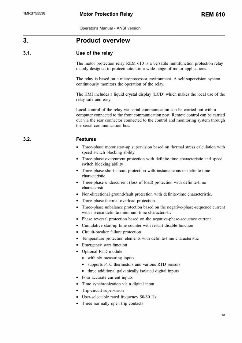
The motor protection relay REM 610 is a versatile multifunction protection relaymainly designed to protectmotors in a wide range of motor applications.
The relay is based on a microprocessor environment. A self-supervision systemcontinuously monitors the operation of the relay.
The HMI includes a liquid crystal display (LCD) which makes the local use of therelay safe and easy.
Local control of the relay via serial communication can be carried out with acomputer connected to the front communication port. Remote control can be carriedout via the rear connector connected to the control and monitoring system throughthe serial communication bus.
3.2. Features
* Three-phase motor start-up supervision based on thermal stress calculation withspeed switch blocking ability
* Three-phase overcurrent protection with definite-time characteristic and speedswitch blocking ability
* Three-phase short-circuit protection with instantaneous or definite-timecharacteristic
* Three-phase undercurrent (loss of load) protection with definite-timecharacteristi
* Non-directional ground-fault protection with definite-time characteristic.* Three-phase thermal overload protection* Three-phase unbalance protection based on the negative-phase-sequence current
with inverse definite minimum time characteristic* Phase reversal protection based on the negative-phase-sequence current* Cumulative start-up time counter with restart disable function* Circuit-breaker failure protection* Temperature protection elements with definite-time characteristic* Emergency start function* Optional RTD module
* with six measuring inputs* supports PTC thermistors and various RTD sensors* three additional galvanically isolated digital inputs
* Four accurate current inputs* Time synchronization via a digital input* Trip-circuit supervision* User-selectable rated frequency 50/60 Hz* Three normally open trip contacts
Motor Protection Relay
Operator's Manual - ANSI version
REM 610REM 6101MRS755538
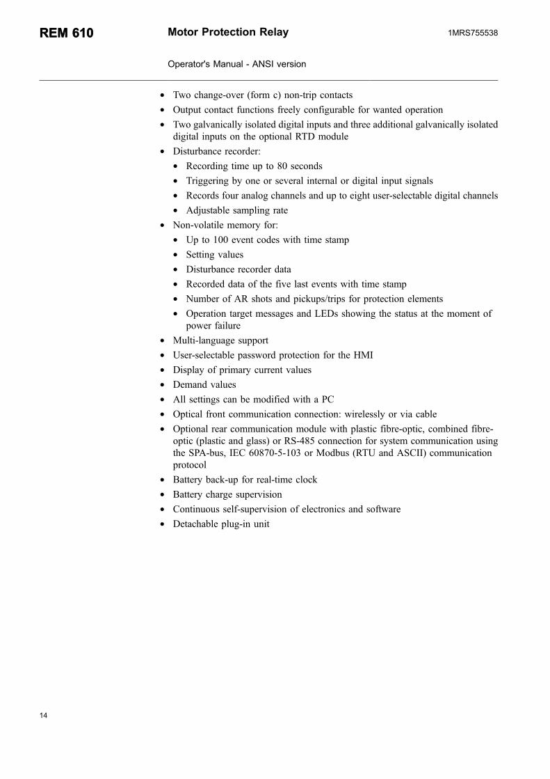
* Two change-over (form c) non-trip contacts* Output contact functions freely configurable for wanted operation* Two galvanically isolated digital inputs and three additional galvanically isolated
digital inputs on the optional RTD module* Disturbance recorder:
* Recording time up to 80 seconds* Triggering by one or several internal or digital input signals* Records four analog channels and up to eight user-selectable digital channels* Adjustable sampling rate
* Non-volatile memory for:* Up to 100 event codes with time stamp* Setting values* Disturbance recorder data* Recorded data of the five last events with time stamp* Number of AR shots and pickups/trips for protection elements* Operation target messages and LEDs showing the status at the moment of
power failure* Multi-language support* User-selectable password protection for the HMI* Display of primary current values* Demand values* All settings can be modified with a PC* Optical front communication connection: wirelessly or via cable* Optional rear communication module with plastic fibre-optic, combined fibre-
optic (plastic and glass) or RS-485 connection for system communication usingthe SPA-bus, IEC 60870-5-103 or Modbus (RTU and ASCII) communicationprotocol
* Battery back-up for real-time clock* Battery charge supervision* Continuous self-supervision of electronics and software* Detachable plug-in unit
14
REM 610REM 610 Motor Protection Relay
Operator's Manual - ANSI version
1MRS755538

15
4. Operation
4.1. HMI features
4.1.1. Front panel
The front panel of the relay contains:
* Alphanumeric 2 × 16 characters’ LCD with backlight and automatic contrastcontrol
* Threetarget LEDs (green, yellow, red) with fixed functionality* Eight programmable target LEDs (red)* HMI push-button section with four arrow buttons and buttons for clear/cancel
and enter, used in navigating in the menu structure and in adjusting setting values* Optically isolated serial communication port with a target LED.
�
�
�
�
�
�
A040215_2
Fig. 4.1.1.-1 Front view of the relay
1) LCD2) HMI push-button section3) Programmable target LEDs (red)4) Target LEDs:
* Left: Ready (green)* Center: Pickup/Alarm (yellow)* Right: Trip (red)
5) Target LED for front communication6) Front communication port (infrared)
4.1.2. How to use the push buttons
The HMI contains push buttons for navigating in the menu.
Motor Protection Relay
Operator's Manual - ANSI version
REM 610REM 6101MRS755538

�� �� ��� ���� ���� ������������������������
A040225
Fig. 4.1.2.-1 Navigation push buttons
Use the navigation buttons to view, select and edit the wanted menu items.
* Activate the main menu by pressing an arrow button.* Move between the menu levels and menu items by using the arrow buttons.* Select the item to be edited or store a new value by pressing .* Increase or decrease the activated digit, shift the activated decimal point, or
navigate between options by using and .* Cancel and return the display to the previous mode (view mode or idle mode), by
pressing
Table 4.1.2.-1 Button navigation and editing
Wanted step or operation Push button
Step downward in the main menu or a submenu
Step upward in the main menu or a submenu
Entering a submenu from the main menu or a higher submenu
Leaving a submenu for the main menu or a higher submenu
Increasing a value in the setting mode
Decreasing a value in the setting mode
Moving the cursor in the setting mode or
Selecting the front connection at power up and
Entering or leaving the setting mode, storing a new value
Entering the monitoring state and
Adjusting the display contrast and or
Resetting or canceling, leaving the setting mode without storing anew value
Resetting latched output contacts in the idle mode for 5 s
Acknowledging and resetting targets, latched output contacts andmemorized values
and
Resetting thermal level to 0 at power up and
4.1.3. Display
4.1.3.1. Display test at power up
When connecting the auxiliary voltage to the relay:
16
REM 610REM 610 Motor Protection Relay
Operator's Manual - ANSI version
1MRS755538

17
1. The backlight is turned on after the relay has performed the internal power-uptests and entered into the protection mode.
2. The display is tested by inverting it for approximately three seconds, seeFig. 4.1.3.1.-1. In case a restart disable target is displayed, the display test willnot be run at power up.
3. The display is returned to the idle mode and the backlight is turned off if nooperation target message is displayed. However, if the non-volatile function isactive, a message shown on the display before the auxiliary voltage wasdisconnected reappears on the display.
A040216
Fig. 4.1.3.1.-1 Display test at power up, display inverted
4.1.3.2. Display modes
When the display is in the idle mode, the name of the motor drive is displayed,which by default is - ABB -. To change the name of the motor drive, use SPAparameter M20.
���������������������������������
A040217
Fig. 4.1.3.2.-1 Display in the idle mode
When the display is in the view mode, you can only view the settings.
�!!"#$ %$�&������������������'��(�)
A040218
Fig. 4.1.3.2.-2 Display in the view mode
When the display is in the setting mode, you can also edit the settings.
�!!"#$ %$�&����������������'��(���
A040219
Fig. 4.1.3.2.-3 Display in the setting mode
Motor Protection Relay
Operator's Manual - ANSI version
REM 610REM 6101MRS755538

4.1.3.3. Display backlight
Normally the backlight of the display is off.
* Turn the backlight on by pressing an arrow button on the HMI. If the HMI panelis not used for approximately five minutes, the backlight is turned offautomatically.
* Activating the power-saving built-in feature by pressing turns the backlightoff within 20 seconds.
4.1.3.4. How to adjust the display contrast
The display contrast is dependent on the temperature. The relay automaticallyadjusts the contrast for optimum readability. When the display is in the idle mode,you can also adjust the contrast manually.
* To increase the contrast, hold down and adjust the contrast using .* To decrease the contrast, hold down and adjust the contrast using .
After power start up of the relay, the factory default value of the display contrast isautomatically restored.
4.1.4. Main menu
The main menu contains six main groups:
* OPERATION* MEASUREMENTS* RECORDED DATA* SETTINGS* CONFIGURATION* INFO
�*�� ���*�#! �*�� ���*�#!
A040228
Fig. 4.1.4.-1 Display showing the first main menu group
* Navigate between the main menu groups by using and .* Return the display to the idle mode by pressing .
The display is returned to the idle mode on expiration of the time out.
18
REM 610REM 610 Motor Protection Relay
Operator's Manual - ANSI version
1MRS755538
19
4.1.5. Submenu
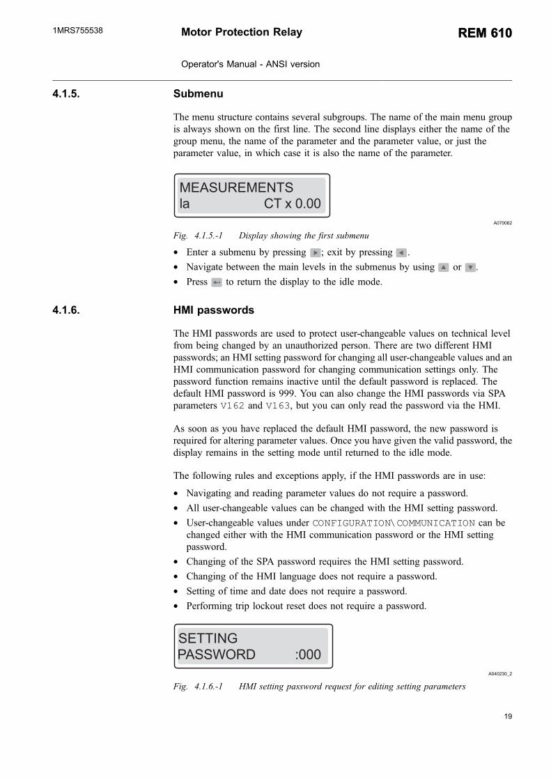
The menu structure contains several subgroups. The name of the main menu groupis always shown on the first line. The second line displays either the name of thegroup menu, the name of the parameter and the parameter value, or just theparameter value, in which case it is also the name of the parameter.
*�� ���*�#! ������������������������!�+�)())
A070062
Fig. 4.1.5.-1 Display showing the first submenu
* Enter a submenu by pressing ; exit by pressing .* Navigate between the main levels in the submenus by using or .* Press to return the display to the idle mode.
4.1.6. HMI passwords
The HMI passwords are used to protect user-changeable values on technical levelfrom being changed by an unauthorized person. There are two different HMIpasswords; an HMI setting password for changing all user-changeable values and anHMI communication password for changing communication settings only. Thepassword function remains inactive until the default password is replaced. Thedefault HMI password is 999. You can also change the HMI passwords via SPAparameters V162 and V163, but you can only read the password via the HMI.
As soon as you have replaced the default HMI password, the new password isrequired for altering parameter values. Once you have given the valid password, thedisplay remains in the setting mode until returned to the idle mode.
The following rules and exceptions apply, if the HMI passwords are in use:
* Navigating and reading parameter values do not require a password.* All user-changeable values can be changed with the HMI setting password.* User-changeable values under CONFIGURATION\COMMUNICATION can be
changed either with the HMI communication password or the HMI settingpassword.
* Changing of the SPA password requires the HMI setting password.* Changing of the HMI language does not require a password.* Setting of time and date does not require a password.* Performing trip lockout reset does not require a password.
&� ,-� �����������'))) �!!"#$
A040230_2
Fig. 4.1.6.-1 HMI setting password request for editing setting parameters
Motor Protection Relay
Operator's Manual - ANSI version
REM 610REM 6101MRS755538

&� ,-� �����������')))�-**�#"��!"-#
A060567
Fig. 4.1.6.-2 HMI communication password request for editing setting parameters
Change the HMI setting password as follows:
1. Press an arrow button to access the main menu.
2. Use the arrow buttons to select CONFIGURATION\HMI PASSWORDS\SETTING PASSWORD and press .
3. Press to enter the setting mode and give the current HMI password ifrequired. If the default password 999 is still valid, no password is required.
4. The first digit of the password to be edited starts to flash. Set the digit usingand .
5. Activate the next digit to be set by pressing or .
6. To store the new password and return the display to the view mode, press .The display confirms the storage by flashing “- - -” once on the display.
Alternatively, to exit the setting mode without storing the password change, pressonce before confirming and the display returns to the view mode.
7. Press to return the display to the idle mode.
The same procedure applies also when changing the HMIcommunication password.
*����*��. $��.��*��. &���/����*��.
�!!"#$
�-#0"$���!"-#
*�� ���*�#!
���-� � � �!�
1*"�&� ,-� !"*�!�"&��"���"!� �&
0��2��#�3
�-#0"$���!"-#0�#�!"-#�!� !� "
�-**�#"��!"-#
��#$��$�*�*-�3� �!!"#$
�!!"#$�&� ,-� �-#0"$���!"-# ������������4���
�����4���
�����/
�������! �"#&�!
"#0-
�-**(�&� ,-�
�-#0"$���!"-#&� ,-� ���������������'+++
!-����-�#!��
A040231_2
Fig. 4.1.6.-3 Changing HMI setting password and HMI communication password.
20
REM 610REM 610 Motor Protection Relay
Operator's Manual - ANSI version
1MRS755538
21
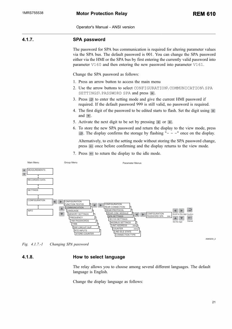
4.1.7. SPA password
The password for SPA bus communication is required for altering parameter valuesvia the SPA bus. The default password is 001. You can change the SPA passwordeither via the HMI or the SPA bus by first entering the currently valid password intoparameter V160 and then entering the new password into parameter V161.
Change the SPA password as follows:
1. Press an arrow button to access the main menu
2. Use the arrow buttons to select CONFIGURATION\COMMUNICATION\SPASETTINGS\PASSWORD SPA and press .
3. Press to enter the setting mode and give the current HMI password ifrequired. If the default password 999 is still valid, no password is required.
4. The first digit of the password to be edited starts to flash. Set the digit usingand .
5. Activate the next digit to be set by pressing or .
6. To store the new SPA password and return the display to the view mode, press. The display confirms the storage by flashing "- - -" once on the display.
Alternatively, to exit the setting mode without storing the SPA password change,press once before confirming and the display returns to the view mode.
7. Press to return the display to the idle mode.
1*"�&� ,-� !"*�
�"#��" ��� !�!�
�-##��!"-#�!3&�
!�"&��"���"!� �&
*����*��. $��.��*��. &���/����*��.5
�!!"#$
�-#0"$���!"-#
*�� ���*�#!
���-� � � �!�
�-�#!��������������������'+++
�#"!�� �� ���������'+++�*- �� � �!!"#$
&�� �!!"#$
�����&�-!-�-�
0��2��#�3
�-#0"$���!"-#0�#�!"-#�!� !� "
�-**�#"��!"-#
��#$��$�
������-##��!"-#�-#0"$���!"-#
*�*-�3� �!!"#$
"���)�� �!!"#$ &� ,-� � &�������'+++�-#0"$���!"-#
�! �"#&�!
������-*(�*- ��� �����/
������
������������4���
�����4���
"#0-
!-����-�#!��
A040233_2
Fig. 4.1.7.-1 Changing SPA password
4.1.8. How to select language
The relay allows you to choose among several different languages. The defaultlanguage is English.
Change the display language as follows:
Motor Protection Relay
Operator's Manual - ANSI version
REM 610REM 6101MRS755538

1. Press an arrow button to access the main menu.
2. Use the arrow buttons to select CONFIGURATION\LANGUAGE and press toenter the currently valid language.
3. Press to enter the setting mode and give the password if required. The secondline starts to flash indicating that you are allowed to set the language.
4. Use or to move the cursor to the wanted language.
5. Press to confirm the selection. The selected language is shown on the display.
6. Press to return the display to the idle mode.
By pressing before confirming the selection, the former language remains activeand the display is returned to the view mode. Pressing again returns the displayto the idle mode.
!�"&��"���"!� �&
*����*��. $��.��*��. &���/����*��.
�����/
������
�!!"#$
�-#0"$���!"-#
*�� ���*�#!
���-� � � �!�
0�#�!"-#�!� !� "
�-**�#"��!"-#
��#$��$�
0��2��#�3
�-#0"$���!"-#
�-#0"$���!"-#
*�*-�3� �!!"#$
1*"�&� ,-�
!"*�
�! �"#&�!
"#0- �#$�" 1
!-����-�#!��
� &�6-�
&-�!�$�7
A070064
Fig. 4.1.8.-1 Selecting language
The list of languages in the language selection menu differs dependingon the HMI language set number in the order number.
4.1.9. How to set the real-time clock
The real-time clock used for time-stamped events is set via two different settings,one for Year-Month-Day and another for Hours-Minutes-Seconds.
To change one setting or both settings:
1. Press an arrow button to access the main menu.
2. Use the arrow buttons to select CONFIGURATION\TIME and press .
3. Use or to select the parameter to be edited.
22
REM 610REM 610 Motor Protection Relay
Operator's Manual - ANSI version
1MRS755538

23
4. Press to enter the setting mode and give the password, if required. If thedefault password 999 is still valid, no password is required.
5. The first digit of the setting value of the parameter to be edited starts to flash.Use and to move the cursor and and to increase or decrease thevalue. The setting range (for example Year or Minutes) is shown on the right-hand side of the second line of the display.
6. To store a new value and return the display to the view mode, press .
7. To exit the setting mode without storing the changes, press once beforeconfirming and the display is returned to the view mode.
8. Press to return the display to the idle mode.
!�"&��"���"!� �&
*����*��. $��.��*��. &���/����*��.
�����/
������
�!!"#$
�-#0"$���!"-#
*�� ���*�#!
���-� � � �!�
0�#�!"-#�!� !� "
�-**�#"��!"-#
��#$��$�
0��2��#�3
�-#0"$���!"-#
�-#0"$���!"-#
*�*-�3� �!!"#$
1*"�&� ,-�
!"*�
�! �"#&�!
"#0-
33�**� �����������8))���9
��(//:55��������������8))��;9
!-����-�#!��
A040237_2
Fig. 4.1.9.-1 Setting the real-time clock
4.1.10. How to switch between front and rear connection
There are two means of serial communication available for the relay: the frontconnection for SPA bus communication and optional rear communication modulesfor communication via the SPA bus, IEC 60870-5-103, MODBUS (RTU or ASCII)protocol.
If the relay is not provided with an optional rear communicationmodule, or if the module has been disabled, the front connection isalways active and switching between front and rear connection is notallowed.
If the optional rear communication module is installed and enabled, the defaultsetting is the rear connection. Switch between front and rear connection as follows:
Motor Protection Relay
Operator's Manual - ANSI version
REM 610REM 6101MRS755538
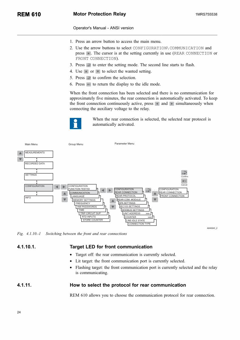
1. Press an arrow button to access the main menu.
2. Use the arrow buttons to select CONFIGURATION\COMMUNICATION andpress . The cursor is at the setting currently in use (REAR CONNECTION orFRONT CONNECTION).
3. Press to enter the setting mode. The second line starts to flash.
4. Use or to select the wanted setting.
5. Press to confirm the selection.
6. Press to return the display to the idle mode.
When the front connection has been selected and there is no communication forapproximately five minutes, the rear connection is automatically activated. To keepthe front connection continuously active, press and simultaneously whenconnecting the auxiliary voltage to the relay.
When the rear connection is selected, the selected rear protocol isautomatically activated.
*����*��. $��.��*��. &���/����*��.
�!!"#$
�-#0"$���!"-#
*�� ���*�#!
���-� � � �!�
"#0-
0�#�!"-#�!� !� "
�-**�#"��!"-#
��#$��$�
0��2��#�3
�-#0"$���!"-#
*�*-�3� �!!"#$
1*"�&� ,-� !"*�
�"#��" ��� !�!��-##��!"-#�!3&�
�-�#!��������������������'+++
�#"!�� �� ��������'+++�*- �� � �!!"#$
&�� �!!"#$
�����&�-!-�-�
������-##��!"-#�-#0"$���!"-#
"���)�� �!!"#$
0�-#!��-##��!"-#
������-##��!"-#�-#0"$���!"-#
�����/
������
�! �"#&�! !�"&��"���"!� �&
������-*(�*- ���
!-����-�#!��
A040243_2
Fig. 4.1.10.-1 Switching between the front and rear connections
4.1.10.1. Target LED for front communication
* Target off: the rear communication is currently selected.* Lit target: the front communication port is currently selected.* Flashing target: the front communication port is currently selected and the relay
is communicating.
4.1.11. How to select the protocol for rear communication
REM 610 allows you to choose the communication protocol for rear connection.
24
REM 610REM 610 Motor Protection Relay
Operator's Manual - ANSI version
1MRS755538

25
The selected protocol is stored in the non-volatile memory and is therefore activatedautomatically after an interruption in the auxiliary voltage.
Select the rear communication protocol as follows:
1. Press an arrow button to access the main menu.
2. Use the arrow buttons to select CONFIGURATION\COMMUNICATION\REARPROTOCOL and press . The cursor is at the setting currently in use (forexample SPA).
3. Press to enter the setting mode. The second line starts to flash.
4. Use or to select the wanted setting.
5. Press to confirm the selection.
6. Press to return the display to the idle mode.
*- �� �� �""
*- �� ��!�
*����*��. $��.��*��. &���/����*��.
�!!"#$
�-#0"$���!"-#
*�� ���*�#!
���-� � � �!�
"����)<=)����)�
&��-#0"$���!"-#
0�#�!"-#�!� !� "
�-**�#"��!"-#
��#$��$�
0��2��#�3
�-#0"$���!"-#
*�*-�3� �!!"#$
1*"�&� ,-� !"*�
�"#��" ��� !�!��-##��!"-#�!3&�
�-�#!���������������������'+++
�#"!�� �� ����������'+++�*- �� � �!!"#$
&�� �!!"#$
�����&�-!-�-�������-##��!"-#�-#0"$���!"-#
"���)�� �!!"#$
�����/
������
�! �"#&�! !�"&��"���"!� �&
������-*(�*- ���"#0-
!-����-�#!��
A040245_2
Fig. 4.1.11.-1 Selecting the communication protocol for the rear connection
4.2. HMI operation levels
The HMI menu consists of a user level and a technical level. The user level is usedfor measuring and monitoring. The technical level is used for advanced protectionrelay setting and can be configured to require a password. The password is requiredafter the default value 999 is replaced.
4.2.1. User level
4.2.1.1. Menu groups of the user level
The user level contains the following menu groups. You can monitor the datawithout a password.
Motor Protection Relay
Operator's Manual - ANSI version
REM 610REM 6101MRS755538
* MEASUREMENTS* Monitored measured values
* RECORDED DATA* Stored event values from the protection functions* Registered number of pickups of protection functions* Continuously updated registers of actual values from protection functions
* INFO* Information on the relay, such as device type and relay serial number
4.2.1.2. How to monitor measured values
You can monitor all measured values via MEASUREMENTS in the HMI menu. Inaddition, the measured current values on phases Ia, Ib and Ic and the measured valueof In can also be monitored by activating the monitoring state.
To access the measured values on phases Ia, Ib and Ic and the measured value of In,TH LEVEL via the HMI menu:
1. Press an arrow button to access the main menu.
2. The cursor is at the first menu item, MEASUREMENTS. Press to see themeasured value on phase Ia.
3. Use and to monitor the measured values on phases Ia, Ib and Ic and themeasured value of In, I2 and TH LEVEL. The phase currents and the value of I2are shown as multiples of the rated current, which correspond to the full loadcurrent (FLC) of the motor. In is shown as a percentage of the rated current of thecurrent transformer (CT) while TH LEVEL is shown as a percentage of thethermal trip level. Press once more to see the corresponding primary currentvalue for Ia, Ib, Ic and In. If the conversion factors are set to zero, dashes "- - -"are displayed instead.
4. Use the arrow buttons to monitor other measured values in the menu DEMANDVALUES; see Fig. 4.2.1.2.-1.
5. Press to return the display to the idle mode.
26
REM 610REM 610 Motor Protection Relay
Operator's Manual - ANSI version
1MRS755538

27
*����*��. $��.��*��. &���/����*��.
�!!"#$
�-#0"$���!"-#
*�� ���*�#!
���-� � � �!�
*�� ���*�#! *�� ���*�#!
*�� ���*�#!
*�� ���*�#!
*�� ���*�#! *�+�"&���������������0��+�+(++
*���"&����������������0��+�+(++*�+�"������������������!>�+(++
*���"�������������������!>�+(++�.�������/���������������'+++
*�� ���*�#!
"�����������������������������"�'+(++
���?��.����������������������5'+++
���/��( ��������0��+�+(++
��/��.� �������������!'+(++
��/��.� �������������!'+(++
*�� ���*�#!
*�� ���*�#! *�+�"&���������������������!'+(++*���"&�����������������������!'+(++*�+�"����������������������!'+(++*���"����������������������!'+(++
1" !-�3� �!� �*�# �?����
�������!� � �!�
!�*&���!���� �!�
"#0-
"� ����������!>�+(++
�� ���������0��+�+(++
�������������������������0��+�+(++
�@���� ��������0��+�+(++
"� �������������!'+(++
�� �������������!'+(++�@ �������������!'+(++
������������������������������!'+(++
�! � ������������A�'B+++�! � ����������A�'B+++
��! �������������������A�'B+++
�! ��� ��A�'B+++�! � ������������A�'B+++�! � ����������A�'B+++
��5(� �5���������������/��'+++
������
���/��( ��������0��+�+(++
�*�+� ��������0��+�+(++ *�+�������������������������!'+(++
!1���?���������������������>'+++
&!�������������������������C��+(+&!�������������������������C��+(+
A070066
Fig. 4.2.1.2.-1 Monitoring measurements
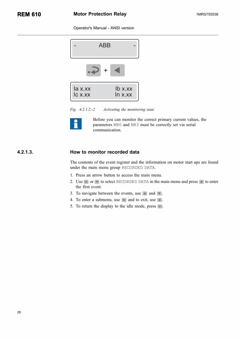
To access the primary current values by activating the monitoring state:
1. Press and simultaneously to view the primary line currents on phases Ia, Iband Ic and the ground-fault current, In.
2. Press to return the display to the idle mode.
The display has to be in the idle mode to be able to activate the monitoring state.The display is not returned to the idle mode automatically as the monitoring statedoes not have a time out. In case a fault is detected, however, the fault targetdisplaces the monitoring state.
Motor Protection Relay
Operator's Manual - ANSI version
REM 610REM 6101MRS755538
B
���������������������������������
"��+(++���������������"@�+(++"��+(++���������������"��+(++
Fig. 4.2.1.2.-2 Activating the monitoring state
Before you can monitor the correct primary current values, theparameters M80 and M83 must be correctly set via serialcommunication.
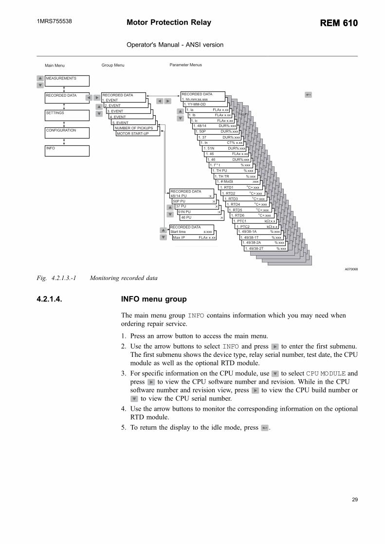
4.2.1.3. How to monitor recorded data
The contents of the event register and the information on motor start ups are foundunder the main menu group RECORDED DATA.
1. Press an arrow button to access the main menu.
2. Use or to select RECORDED DATA in the main menu and press to enterthe first event.
3. To navigate between the events, use and .
4. To enter a submenu, use and to exit, use .
5. To return the display to the idle mode, press .
28
REM 610REM 610 Motor Protection Relay
Operator's Manual - ANSI version
1MRS755538
29
*-!-�� !��!��&
*����*��. $��.��*��. &���/����*��.5
�!!"#$
�-#0"$���!"-#
*�� ���*�#!
���-� � � �!�
#�*����-0�&"�D�& �(��?�#!
�(��?�#!
�(��?�#!
���-� � � �!��(��?�#!
�(��?�#!
���-� � � �!�
���-� � � �!�
���-� � � �!�
�(��;��<�����������������>'+++
�(��;��<��!�������������>'+++
�(��;��<�����������������>'+++
�(��;��<��!�������������>'+++
"#0-
�(�&!�� �������������C�'+(+�(�&!���� ������������C�'+(+
�(��! ���������������A�B'+++
�(��� ��������0��+�+(++�(��@ ��������0��+�+(++
�(��� ��������0��+�+(++
�(��)& ������� ��>'+++
�(��<��� ������� ��>'+++
�(��= ������ ��>'+++�(�"� ���������!>�+(++
�(��� ��������0��+�+(++
�(��� �������� ��>'+++
�(�"��%����������������������>'+++
�(���# ������ ��>'+++
�(�E�*� �����������������'+++
�(��! � ��������A�B'+++
�(��! � ���������A�B'+++�(��! � ���������A�B'+++�(��! ���������������A�B'+++
�(��! � ���������A�B'+++
�(���(//:55(555�(�33�**�
*�+�"& �����0��+�+(++
����/�������������������5'+++
�<����&����������������������'+
�=�&������������������������������'+
��#�&����������������������������'+
���&������������������������������'+
�)&�&����������������������������'+
�(�!1�&��� �������������>'+++
�(�!1�!��� �������������>'+++
������
A070068
Fig. 4.2.1.3.-1 Monitoring recorded data
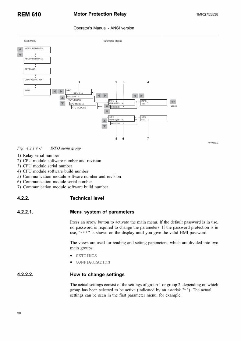
4.2.1.4. INFO menu group
The main menu group INFO contains information which you may need whenordering repair service.
1. Press an arrow button to access the main menu.
2. Use the arrow buttons to select INFO and press to enter the first submenu.The first submenu shows the device type, relay serial number, test date, the CPUmodule as well as the optional RTD module.
3. For specific information on the CPU module, use to select CPU MODULE andpress to view the CPU software number and revision. While in the CPUsoftware number and revision view, press to view the CPU build number or
to view the CPU serial number.
4. Use the arrow buttons to monitor the corresponding information on the optionalRTD module.
5. To return the display to the idle mode, press .
Motor Protection Relay
Operator's Manual - ANSI version
REM 610REM 6101MRS755538
� � � �
� � �
*����*��. &���/����*��.5
�!!"#$
�-#0"$���!"-#
*�� ���*�#!
���-� � � �!�
��*���)
�! �*- ���
"#0-
++++++++
3333**
�&��*- ���
"#0-
�*� ��<������"#0-
�*� ��<�����
++++++++
+++
++++++++
�"#0-�+++
�"#0- "#0-
�������
A040252_2
Fig. 4.2.1.4.-1 INFO menu group
1) Relay serial number2) CPU module software number and revision3) CPU module serial number4) CPU module software build number5) Communication module software number and revision6) Communication module serial number7) Communication module software build number
4.2.2. Technical level
4.2.2.1. Menu system of parameters
Press an arrow button to activate the main menu. If the default password is in use,no password is required to change the parameters. If the password protection is inuse, "***" is shown on the display until you give the valid HMI password.
The views are used for reading and setting parameters, which are divided into twomain groups:
* SETTINGS* CONFIGURATION
4.2.2.2. How to change settings
The actual settings consist of the settings of group 1 or group 2, depending on whichgroup has been selected to be active (indicated by an asterisk "*"). The actualsettings can be seen in the first parameter menu, for example:
30
REM 610REM 610 Motor Protection Relay
Operator's Manual - ANSI version
1MRS755538

31
SETTINGS\PROTECT. ELEMENTS\48/14 FLAx x.xx
.@/��. &���/����*��.
�!!"#$
��$�&��������������������������'+(++
%�$�&�����������������������'+(++ �!!"#$
�����/
������
�<��� ��������0��+�+(++
A070076
Fig. 4.2.2.2.-1 Setting parameters in setting group 1 and setting group 2
By switching between setting groups 1 and 2, you can activate a whole group ofsettings at the same time. Switch between the setting groups as follows:
* With the parameter GROUP 1/GROUP 2 under the main menu groupSETTINGS.
* With a digital input signal, provided that SGB1...5/4 has been set to 1 in bothsetting groups (GRP1 and GRP2).
* With parameter V150 via the SPA bus.
When a large number of settings is to be altered, for example duringthe commissioning of the relay systems, use a PC equipped with thenecessary software.
If no PC is available, or when only a few settings are to be altered:
1. Press an arrow button to access the main menu.
2. Use the arrow buttons to select the main menu group SETTINGS and the wantedgroup menu (for example PROTEC. ELEMENTS), and press .
3. Use or to select the parameter to be changed and press .
4. Use or to select setting group 1 or 2 (GRP1 or GRP2). The active settinggroup is indicated by an asterisk "*".
5. Enter the setting mode by pressing and give the password if required. If thedefault password 999 is still valid, no password is required.
6. The first digit of the setting value of the parameter to be edited starts to flash.Use and to move the cursor and and to increase or decrease thenumber.
7. To store a new value and return the display to the view mode, press . If theparameter is of a numerical kind, the display confirms the storage by flashing "-- -" once on the display.
8. To exit the setting mode without storing the changes, press once beforeconfirming and the display returns to the view mode.
9. Press to return the display to the idle mode.
Motor Protection Relay
Operator's Manual - ANSI version
REM 610REM 6101MRS755538

��;�����*��������������>'+++
��;��� ! " ������������>'+++
��$�&��������������������������'+(++%�$�&������������������������'+(++ �!!"#$
�!!"#$ $�-�&���$�-�&��
#�,�!�"&�!��$�! �*�# � �!!"#$
*����*��. $��.��*��. &���/����*��.5
�!!"#$
�-#0"$���!"-#
*�� ���*�#!
���-� � � �!�
�!!"#$
&�-!��!(����*�#! �!!"#$
��$�&��������������������������'+(++
%�$�&������������������������'+(++ �!!"#$
�!!"#$
�!!"#$
��$�&����������������������������'+++
%�$�&�������������������������'+++ �!!"#$
���$�&���������������������������'+(+%�$�&�������������������������'+(+
��$�&����������������������������'+(+
%�$�&�������������������������'+(+
��$�&���������������������������'+++%�$�&�������������������������'+++
�!!"#$
�!!"#$
�!!"#$
�!!"#$ �!!"#$�$�-�&��
�!!"#$
�*�# �?������������'+++ �!!"#$
�� �!!"#$�$�-�&��
�!!"#$ �!!"#$�$�-�&��
" ���� �*"#�����������'+++
�<��<������*�#!
�<��<������*�#!
$�
$0
$�
$�
�4�������/
������
0��� ��-# ��3
�!!"#$ 0��� ��(�������������������'+(++
�! �! ����������������A�'+++�! �!�! �3�������������5'+++
��! �! ��������������A�'+++
�! �� �������������A�'+++��! ���! �3������������5'+++
���! �!�! �3�������������5'+++
&!�� ������������C�'+(+
��! �! ��������������A�'+++
�! �� �������������A�'+++��! ���! �3
���! �!�! �3�������������5'+++
�! �� �������������A�'+++�! ���! �3�������������5'+++
�&!�� ������������C�'+(+
!� �� ����������������A�'+++�! ���! �3�������������5'+++
�! �� ��������������A�'+++
��! �! ��������������A�'+++
�! �! ��������������A�'+++�! �!�! �3�������������5'+++
�! ���! �3���������������5'+++
��! �!�! �3���������������5'+++
�! �� �������������A�'+++�! ���! �3�������������5'+++�! �! ����������������A�'+++�! �!�! �3�������������5'+++
D� ������������������'�++
��� ���������������5'+++
�+ ���������������5'+(++
� ���������������>'+++
!�/@ ���������������A�'�++
�����--�������������������5��'+++
!����0��� ���������������5'+(++
�)& ���������0��+�+(++
�)&�! �3 ����������������'+(++�= ���������������>'�++
��# ����������!>�+(++
�<��� ��������0��+�+(++
�<����! �3����������������'+(++
�=�! �3 �����������������5'+++
��#�! �3 �����������������5'+(++
�� ��������0��+�+(++
���! "�� �����������������'+++
"#0-
A070071
Fig. 4.2.2.2.-2 SETTINGS menu
32
REM 610REM 610 Motor Protection Relay
Operator's Manual - ANSI version
1MRS755538

33
Switchgroups
The relay contains the following switchgroups:
SGF1 Output contacts
SGF2 Display settings
SGF3, SGF4 Protection functions
SGF5 Latching feature for programmable LEDs
SGB1...SGB5 Digital inputs (DI1...DI5)
SGR1...SGR5 Output contacts (PO1, PO2, PO3, SO1, SO2)
SGL1...SGL8 Programmable LEDs
To set functions via switchgroups:
1. Press an arrow button to access the main menu.
2. Use the arrow buttons to select the main menu group SETTINGS and the wantedswitchgroup menu (for example SGF), and press .
3. Use or to select the wanted switchgroup (for example SGF2 for displaysettings) and press .
4. Use or to select setting group 1 or 2 (GRP1 or GRP2). The active settinggroup is indicated by an asterisk “*”.
5. Press to enter the setting mode and give the password if required.
6. Use or to select the bit to be set, and or to select the wanted bitstate, see Fig. 4.2.2.2.-4.
7. Press to confirm the selection. After confirmation, the display returns to theview mode and shows the checksum of the switchgroup.
8. Press to return the display to the idle mode.
Motor Protection Relay
Operator's Manual - ANSI version
REM 610REM 6101MRS755538

*����*��. $��.��*��. &���/����*��.5
�!!"#$
�-#0"$���!"-#
*�� ���*�#!
���-� � � �!�
$�-�&���$�-�&��
#�,�!�"&�"# (
�*�# � �!!"#$
�!!"#$
&�-!��!(����*�#! �!!"#$ �!!"#$
%�$�&�������������������������'+++
�$�&���������������������������'+++
��$�&�������������������'++++++++
�!!"#$ %�$�&����������������'++++++++
��$�&�������������������������'++++
�!!"#$ %�$�&�����������������������'++++
�!!"#$
�!!"#$
�!!"#$
��$�&�����������������'++++++++
�!!"#$ %�$�&����������������'++++++++
$�
$0
$�
$�
�;��<������*�#!
�;��<������*�#!
$�����������������������'++++++
$����� ������������'++++++
$�����������������������'++++++ $�����������������������'++++++
$�����������������������'++++++
$���������������������'+++++++
$�� ����������'+++++++
$����� ����������'+++++++
$����� ����������'+++++++
$��� ����������'+++++++
$�=��� ����������'+++++++
$��� ����������'+++++++
$�<��� ����������'+++++++
$0���� �����������������'+++
$0���� ����������������'+++
$0���� �����������������'+++
$0���� ����������� �'+
$0���� ����������������'+++
$����� ���������������'+++++
$�������������������������'+++++
$����� ���������������'+++++ $����� ���������������'+++++
$����� ��������������'+++++
�4�������/
������
0��� ��-# ��3
"#0-
A070079
Fig. 4.2.2.2.-3 Settings for switchgroups
&���/����*��.
%�$�&�������������������������'+++ �!!"#$
$�&���������������������������'+++%�$�&�������������������������'+�+ �!!"#$
������������4�5���4�@� �����@��5���8)�����9
�����/
������
A040259
Fig. 4.2.2.2.-4 Setting bits
4.2.2.3. Configuration
In general, the parameters found under CONFIGURATION are set only once by thecustomer, that is, prior to commissioning of the relay.
34
REM 610REM 610 Motor Protection Relay
Operator's Manual - ANSI version
1MRS755538

35
To change a parameter:
1. Press an arrow button to access the main menu.
2. Use the arrow buttons to select the main menu group CONFIGURATION and thewanted group menu, and press .
3. Use or to select the wanted parameter (for example UNIT ADDRESS :xxx) or a set of parameters (for example SPA SETTINGS). In case of a set ofparameters, use arrow buttons until you reach the wanted parameter.
4. Press to enter the setting mode and give the password if required.
5. The parameter text (enumerator) or the first digit of the parameter setting valuestarts to flash. Set the enumerator or the digit/character by using and .Activate the next digit/character to be set by pressing or . When setting anenumerator, however, the left and right arrows have no function.
6. To store a new value and return the display to the view mode, press . If theparameter is of numerical kind, the display confirms the storage by flashing "- --" once on the display.
7. To exit the setting mode without storing the changes, press once beforeconfirming and the display returns to the view mode.
8. Press once more to return the display to the idle mode.
If a setting value outside the allowed limits is confirmed in the settingmode, the former value is restored.
Motor Protection Relay
Operator's Manual - ANSI version
REM 610REM 6101MRS755538

��� ���!����������������';(�
1*"�&� ,-� !"*�
�"#��" ��� !�!�
�-##��!"-#�!3&�
!�"&��"���"!� �&
*����*��. $��.��*��. &���/����*��.5
�!!"#$
�-#0"$���!"-#
*�� ���*�#!
���-� � � �!�
�-#0"$���!"-#
�-�#!��������������������'+++
�#"!�� �� ���������'+++�*- �� � �!!"#$
&�� �!!"#$
�����&�-!-�-�
�-#0"$���!"-# "�� !�!� �������������������'+
"�� !�!� �������������������'+ "�� !�!� ��������������������'+ "�� !�!� ��������������������'+
"�� !�!� ��������������������'+0��2��#�3
�-#0"$���!"-#0�#�!"-#�!� !� "
�-**�#"��!"-#
��#$��$�
0�-#!��-##��!"-#������-##��!"-#�-#0"$���!"-#
�� �!� ! "� !�!� 0�#�(!� !������������������'+�-#0"$���!"-#
������-##��!"-#�-#0"$���!"-#
*- �� �� �""
�*- �� ��!�
�-#0"$���!"-#
"����)<=)����)�
&�
����-� ���-,�1"$1
�?�#�&��"!3
- �&��"!3�#-�&��"!3
�-#0"$���!"-#
*�*-�3� �!!"#$
"���)�� �!!"#$
��� ���!�����������������';(�
&� ,-� � &��������'+++�-#0"$���!"-#
" ���� �#���� �-#0"$���!"-#
!���--&�-#0"$���!"-#
�"$1!�-00�-#0"$���!"-#
*�*(� �!!"#$ �������'+++
�! �"#&�!
������-*(�*- ���
�-#0"$���!"-#
��� ���!�����������������'�(<
��� ���!����������������';(�
"���)�� �!���������������'�
�-#0"$���!"-#
"���)�� �!���������������'�
��� ���!����������������'�(<
�-#0"$���!"-#
��� ���!����������������'�(<
��� ���!����������������'�(���� ���!����������������'�(���� ���!����������������')(�
1"$1��-,
�"$1!�-#
�-#0"$���!"-#
�-#0"$���!"-#
�-#0"$���!"-#
"#0-
� &�6-�
&-�!�$�7
�#$�" 1
!-����-�#!��
A070073
Fig. 4.2.2.3.-1 CONFIGURATION menu, part 1
36
REM 610REM 610 Motor Protection Relay
Operator's Manual - ANSI version
1MRS755538
37
�#-!�"#�� ��&��))�������������������((��)
1*"�&� ,-� !"*�
!�"&��"���"!� �&
*����*��. $��.��*��. &���/����*��.5
�!!"#$
�-#0"$���!"-#
*�� ���*�#!
���-� � � �!�
�-#0"$���!"-#
0��2��#�3��������������'�)
�-#0"$���!"-#0��2��#�3��������������'�)0��2��#�3
�-#0"$���!"-#0�#�!"-#�!� !� "
�-**�#"��!"-#
��#$��$�
*�*-�3� �!!"#$
�!!"#$�&� ,-� �-#0"$���!"-#
��(//:55
�-#0"$���!"-#33�**�
�-#0"$���!"-#�#-!�"#�� ��&�))��������������������((��)
�&��)���������������������((��)
�&�)))�������������������((��)
�#��))��������������������((��)
�#���)���������������������((��)
�! �"#&�!
!� ��#����
�-#0"$���!"-#�1����! �!1
�1����! �1����! �1����! �!1�1����! �1����!
!� � " ����
�.�)����������������������((��)#���)� �����������������((��)�&!����������������������)((�)C�
�-#0"$���!"-#
�&��)���������������������((��)�&�)))�������������������((��)�#��))���������������������((��)�#���)����������������������((��)�.�)�����������������������((��)#���)� ��������������������((��)
�-#0"$���!"-#�#-!�"#�� ��&��))��������������������((��)�&��)���������������������((��)�&�)))��������������������((��)�#��))������������������������((��)�#���)�����������������������((��)�.�)�������������������������((��)#���)� ��������������������((��)�&!������������������������)((�)C�
�-#0"$���!"-#�#-!�"#�� ��&��))���������������������((��)�&��)����������������������((��)�&�)))����������������������((��)�#��))�������������������������((��)�#���)�����������������������((��)�.�)������������������������((��)#���)� ������������������((��)
"#0-
�-**(�&� ,-� !-����-�#!��
�-#0"$���!"-# !-����#!�����������������')
A040263_2
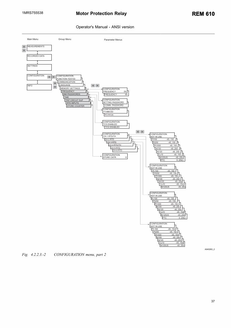
Fig. 4.2.2.3.-2 CONFIGURATION menu, part 2
Motor Protection Relay
Operator's Manual - ANSI version
REM 610REM 6101MRS755538

4.2.2.4. How to acknowledge and reset targets, output contacts andmemorized values
* To clear the LEDs and the display, press . The LEDs and the display arecleared only if the fault has disappeared.
* To unlatch the output contacts, press for at least five seconds. Note that theLEDs and the display have to be cleared before this.
* Press and simultaneously for at least half a second to perform a masterreset, that is, to clear targets and memorized values and to unlatch the outputcontacts. The display being inverted confirms this action. Memorized valuesinclude recorded data, disturbance recorder data and average values (demandvalues and history data values, except for the running time).
4.3. Protection relay targets
The operation of the relay can be monitored by means of three different HMItargets:
* Three target LEDs with fixed functionality:* Ready* Pickup/Alarm* Trip
* Eight programmable target LEDs* Text message on the display
The protection functions are not affected by fault targets.
4.3.1. Target LEDs
When a protection element picks up or generates an alarm, the yellow target LED islit.
When a protection element trips, the yellow target LED remains lit and the red targetLED is lit.
When a picked up protection element is blocked, the yellow target LED starts toflash. The yellow target LED is also lit to indicate an alarm from a protectionelement.
4.3.1.1. Green target LED
A040264
Fig. 4.3.1.1.-1 Green target LED
Two different functions are embedded in the green target LED: power on andinternal relay fault (IRF).
38
REM 610REM 610 Motor Protection Relay
Operator's Manual - ANSI version
1MRS755538

39
* Target off:
The auxiliary voltage is not connected.
* Lit target:
The relay is in operation. However, a less severe fault (warning) may haveoccurred. Refer to Section 4.3.2.3. Self-supervision.
* Flashing target:
An internal relay fault requiring repair by an authorized service supplier hasoccurred. Refer to Section 4.3.2.3. Self-supervision.
4.3.1.2. Yellow target LED
A040266
Fig. 4.3.1.2.-1 Yellow target LED
* Target off:
No protection element has picked up and there are no thermal alarms.
* Lit target:
A protection element has picked up or generated an alarm. The pickup and alarmtarget can be selected to be either latching or non-latching with the SGFswitches. A non-latching target is automatically cleared when the fault hasdisappeared and the protection element has been reset, whereas a latching targetremains lit until manually cleared.
* Flashing target:
Pickup protection elements have been blocked by an external digital input signal.The blocking target is non-latching, that is, it disappears with the digital inputsignal.
The yellow target LED continues flashing for as long as a protection elementremains blocked. The blocking target disappears with the digital input signal orwhen the protection element is no longer picked up.
If a protection element is blocked when other protection elements are picked up, thetarget continues flashing. This is because a blocking target has a higher priority thana pickup target.
4.3.1.3. Red target LED
A040265
Fig. 4.3.1.3.-1 Red target LED
Motor Protection Relay
Operator's Manual - ANSI version
REM 610REM 6101MRS755538
* Target off:
No protection element has tripped.
* Lit target:
A protection element has tripped. The trip target is latching, that is, it remains lituntil manually cleared.
* Flashing target:
CB Fail element has tripped. The target is latching, that is, it remains flashinguntil manually cleared.
4.3.1.4. Programmable target LEDs
In addition to the three fixed LEDs, the relay contains eight LEDs which you canprogram to target the status of different type of relay signals. The programmableLEDs can target the following information:
* Trip signals from protection elements* Alarm signals from protection elements* Motor status and restart disable status* Status of the digital input signals
Route the signals to the LEDs via switchgroups SGL1...SGL8; to LED1 with theswitches of switchgroup SGL1, to LED2 with those of SGL2, and so forth.
For detailed information on the signals, refer to the Technical Reference Manual.
The LEDs are non-latching by default but you can also set them to operate aslatching via switchgroup SGF5.
For instructions on setting the switchgroups, refer to Section 4.2.2.2. How to changesettings.
4.3.2. Target messages
The messages give an overview of protection operations and internal relay faults.
4.3.2.1. Operation target messages
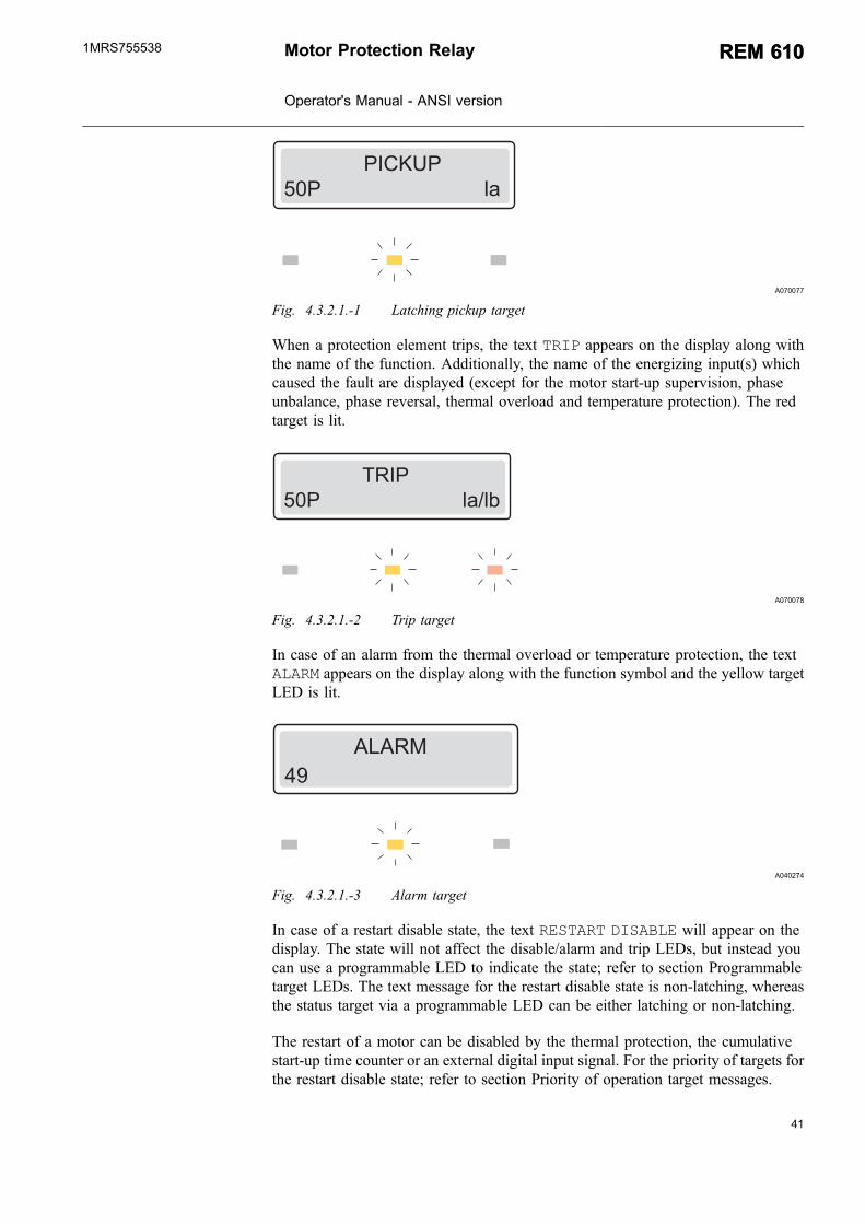
When a protection element picks up, the text PICKUP appears on the display alongwith the name of the function. Additionally, in case of a latching pick up target, thename of the energizing input(s) which caused the fault are displayed (except for themotor start-up supervision based on thermal stress calculation and the unbalanceprotection). The yellow target LED is lit.
40
REM 610REM 610 Motor Protection Relay
Operator's Manual - ANSI version
1MRS755538
41
&"�D�&�)&������������������������� ��
A070077
Fig. 4.3.2.1.-1 Latching pickup target
When a protection element trips, the text TRIP appears on the display along withthe name of the function. Additionally, the name of the energizing input(s) whichcaused the fault are displayed (except for the motor start-up supervision, phaseunbalance, phase reversal, thermal overload and temperature protection). The redtarget is lit.
!�"&�)&�����������������������������@
A070078
Fig. 4.3.2.1.-2 Trip target
In case of an alarm from the thermal overload or temperature protection, the textALARM appears on the display along with the function symbol and the yellow targetLED is lit.
����*�;
A040274
Fig. 4.3.2.1.-3 Alarm target
In case of a restart disable state, the text RESTART DISABLE will appear on thedisplay. The state will not affect the disable/alarm and trip LEDs, but instead youcan use a programmable LED to indicate the state; refer to section Programmabletarget LEDs. The text message for the restart disable state is non-latching, whereasthe status target via a programmable LED can be either latching or non-latching.
The restart of a motor can be disabled by the thermal protection, the cumulativestart-up time counter or an external digital input signal. For the priority of targets forthe restart disable state; refer to section Priority of operation target messages.
Motor Protection Relay
Operator's Manual - ANSI version
REM 610REM 6101MRS755538

�� !��!� " ������
A040273_2
Fig. 4.3.2.1.-4 Restart disable target
Latching and non-latching targets
A latching operation target message remains on the display until manually cleared oruntil replaced by a message of higher priority. However, if the fault is stable and hasnot disappeared, the operation target message and the LED(s) are not cleared. Anoperation target generated by a non-latching pickup is automatically cleared whenthe element is reset.
Priority of operation target messages
The messages on the display have a certain priority order. If different types of targetsare activated simultaneously, the message with the highest priority appears on thedisplay.
The priority order of the messages:
1. CBFAIL
2. Trip
3. Pickup/Alarm
4. Restart disable
4.1. Thermal protection
4.2. Cumulative start-up time counter
4.3. External restart disable
When several protection elements generate pickups or alarms, the last pickup/alarmtarget message is displayed. When several protection elements trip, the first triptarget message is displayed until the time, as specified by the NEW TRIP IND.setting value, has expired. After this, a new trip target message can replace the oldone. A hidden trip target message can be brought forward by pressing .
4.3.2.2. Disturbance recorder target
When the display is in the idle mode, an asterisk “*” indicating that the disturbancerecorder has been triggered and is ready to be unloaded, is shown in the lower right-hand corner of the display. Disturbance recorder status target can also be routed tothe programmable LEDs.
42
REM 610REM 610 Motor Protection Relay
Operator's Manual - ANSI version
1MRS755538

43
4.3.2.3. Self-supervision
There are two types of fault targets; internal relay fault (IRF) targets and warnings.Internal relay faults prevent relay operation. Warnings are less severe faults andcontinued relay operation with full or reduced functionality is allowed.
Internal relay fault (IRF)
At permanent internal relay faults, the relay is no longer protecting and has to besent for repair at an authorized service supplier. When the self-supervision systemdetects a permanent internal relay fault, the green target LED starts to flash. The textINTERNAL FAULT and a fault code appear on the display.
State the fault code when sending the relay for service.
As long as the green target LED (ready) is flashing, the fault target cannot becleared. In case an internal fault disappears, the green target LED stops flashing andthe relay is returned to the normal service state, but the fault target message remainson the display until manually cleared, or until a motor start up begins.
"#!��#���0���!0���!��- ���'�)
A040278
Fig. 4.3.2.3.-1 Permanent IRF
The fault code is a number which identifies the fault type. The fault codes are listedin the table below:
Table 4.3.2.3.-1 IRF codes
Fault code Type of fault
4 Error in output relay PO1
5 Error in output relay PO2
6 Error in output relay PO3
7 Error in output relay SO1
8 Error in output relay SO2
9 Error in the enable signal for output relays PO1,PO2,SO1,SO2
10, 11, 12 Error in the feedback, enable signal or output relays PO1,PO2,SO1,SO2
20, 21 Auxiliary voltage dip
30 Faulty program memory
50, 59 Faulty work memory
Motor Protection Relay
Operator's Manual - ANSI version
REM 610REM 6101MRS755538

Table 4.3.2.3.-1 IRF codes (Continued)
Fault code Type of fault
51, 52, 53a), 54, 56 Faulty parameter memoryb)
55 Faulty parameter memory, calibration parameters
75 RTD module faulty
80 RTD module missing
81 RTD module unknown
82 RTD module configuration error
85 Power supply module faulty
86 Power supply module unknown
90 Hardware configuration error
95 Communication module unknown
104 Faulty configuration set for IEC 60870-5-103
131, 139, 195, 203, 222, 223 Internal reference voltage error
253 Error in the measuring unita) All setting values will be zero during the faultb) May be corrected by formatting to the factory setting.
Warning
In case of a less severe fault (warning), the relay continues to operate except forthose protection functions possibly affected by the fault. At this type of fault, thegreen target LED remains lit as during normal operation, but the text WARNINGwith a fault code or a text message indicating the fault type replaces the name of thefeeder on the display in the idle mode. Some of these faults can be corrected by arelay operator at site. After the fault has disappeared or been corrected, the messageis automatically cleared.
,��#"#$��!!��3��-,
A040279
Fig. 4.3.2.3.-2 Warning with text message
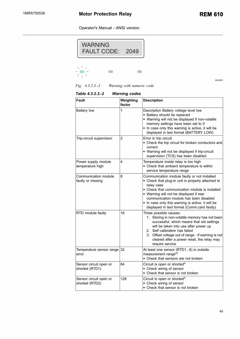
If more than one type of fault occur at the same time, one single numeric code whichindicates all the faults is displayed. For instance, 2049 implies two faults: thebattery is low and the temperature sensor RTD6 is faulty. The code is composed ofthe weighting factors assigned to each fault type as follows: 1 + 2048; seeTable 4.3.2.3.-2
44
REM 610REM 610 Motor Protection Relay
Operator's Manual - ANSI version
1MRS755538
45
,��#"#$0���!��- �'�����)�;
A040281
Fig. 4.3.2.3.-3 Warning with numeric code
Table 4.3.2.3.-2 Warning codes
Fault Weightingfactor
Description
Battery low 1 Description Battery voltage level low* Battery should be replaced* Warning will not be displayed if non-volatilememory settings have been set to 0
* In case only this warning is active, it will bedisplayed in text format (BATTERY LOW)
Trip-circuit supervision 2 Error in trip circuit* Check the trip circuit for broken conductors andcorrect.
* Warning will not be displayed if trip-circuitsupervision (TCS) has been disabled
Power supply moduletemperature high
4 Temperature inside relay is too high* Check that ambient temperature is withinservice temperature range
Communication modulefaulty or missing
8 Communication module faulty or not installed* Check that plug-in unit is properly attached torelay case
* Check that communication module is installed* Warning will not be displayed if rearcommunication module has been disabled
* In case only this warning is active, it will bedisplayed in text format (Comm.card faulty)
RTD module faulty 16 Three possible causes:1. Storing in non-volatile memory has not been
successful, which means that old settingswill be taken into use after power up
2. Self calibration has failed3. Offset voltage out of range - If warning is not
cleared after a power reset, the relay mayrequire service
Temperature sensor rangeerror
32 At least one sensor (RTD1...6) is outsidemeasurement rangea)
* Check that sensors are not broken
Sensor circuit open orshorted (RTD1)
64 Circuit is open or shorteda
* Check wiring of sensor* Check that sensor is not broken
Sensor circuit open orshorted (RTD2)
128 Circuit is open or shorteda
* Check wiring of sensor* Check that sensor is not broken
Motor Protection Relay
Operator's Manual - ANSI version
REM 610REM 6101MRS755538

Table 4.3.2.3.-2 Warning codes (Continued)
Fault Weightingfactor
Description
Sensor circuit open orshorted (RTD3)
256 Circuit is open or shorteda
* Check wiring of sensor* Check that sensor is not broken
Sensor circuit open orshorted (RTD4)
512 Circuit is open or shorteda
* Check wiring of sensor* Check that sensor is not broken
Sensor circuit open orshorted (RTD5)
1024 Circuit is open or shorteda
* Check wiring of sensor* Check that sensor is not broken
Sensor circuit open orshorted (RTD6)
2048 Circuit is open or shorteda
* Check wiring of sensor* Check that sensor is not broken
Thermistor circuit open orshorted (Thermistor1)
4096 Circuit is open or shorteda
* Check wiring of sensor* Check that sensor is not broken
Thermistor circuit open orshorted (Thermistor2)
8192 Circuit is open or shorteda
* Check wiring of sensor* Check that sensor is not broken
Σ: 16383a) Temperature protection elements are out of operation
4.4. Detachable plug-in unit
4.4.1. Identifying the product
You can find the order number on a label under the lower handle of the relay.
When checking the order number of the relay plug-in unit, be carefulnot to lift the handle more than 25º (approx. 40 mm). Lifting the handleany further detaches the plug-in unit from the case.
46
REM 610REM 610 Motor Protection Relay
Operator's Manual - ANSI version
1MRS755538

47
� FA040165
Fig. 4.4.1.-1 Checking the order number of the relay
α = 25ºy = 40 mm
4.4.2. Detaching and installing the plug-in unit
Before detaching the plug-in unit from the case, the auxiliary voltagemust be disconnected.
To detach the plug-in unit:
1. Lift the lower handle until the spring-loaded locks on both sides of the handle arereleased and the unit is pushed about 6 mm out of the case. This separates theconnectors.
2. Pull the unit out of the case.
The relay features an automatic short-circuit mechanism in the current transformer(CT) connector. Therefore, detaching the plug-in unit will not open the secondarycircuit of the CT which otherwise could cause dangerously high voltages.
Signal connectors are left open when the plug-in unit is detached.
Motor Protection Relay
Operator's Manual - ANSI version
REM 610REM 6101MRS755538

A040166
Fig. 4.4.2.-1 Detaching a plug-in unit from the case
Before fitting a relay plug-in unit into a relay case, check that the unitand the case have the same order number.
The order number of the case is printed on the bottom plate inside the case.However, if a substitute plug-in unit has to be used instead of the original unit,ensure that at least the first 10 characters in the order numbers of the case and theplug-in unit are identical, as in the following example:
Order number of the relay case REM610C55HCMP XX
Order number of the plug-in unit REM610C55HCNR XX
However, it is highly recommended that all characters in the order number of thesubstitute plug-in unit, except for those indicating a spare part, should match theones of the case. Otherwise, it may result in loss of significant functionality in theapplication.
The relay features a built-in mechanical coding system which helps to preventdangerous situations from arising in case a non-suitable plug-in unit is fitted into arelay case.
Forcing a non-suitable plug-in unit into a case breaks the relay and maycause dangerous situations.
When installing a plug-in unit into a case:
1. Check that the handle is down in its initial position.
2. Push the unit into the case until the locks click; see Fig. 4.4.2.-2.
48
REM 610REM 610 Motor Protection Relay
Operator's Manual - ANSI version
1MRS755538

49
A040167
Fig. 4.4.2.-2 Installing a plug-in unit into the case
4.4.3. Inserting and changing the battery
The battery may only be inserted and changed by trained servicepersonnel.
To insert or change the battery, first detach the plug-in unit; refer to Section 4.4.2.Detaching and installing the plug-in unit.
The battery compartment is accessible from underneath the plug-in unit as shown inFig. 4.4.3.-1.
1. Gently remove the battery with, for example, a flat-ended screwdriver. Be carefulnot to drop the battery inside the plug-in unit.
2. Insert a new battery under the battery holder and ensure that you install thebattery with the correct polarity to avoid damage to the equipment.
3. Dispose the removed battery according to local environmental regulations on thedisposal of lithium batteries.
The battery is not being charged during normal operation.
When the relay is taken out of service, the battery should be removed to avoiddischarge. Typical battery discharge time is 14 days.
Motor Protection Relay
Operator's Manual - ANSI version
REM 610REM 6101MRS755538

�
�
�
A040282_2
Fig. 4.4.3.-1 Inserting and changing the battery
A) Battery holderB) Note! PolarityC) Battery
50
REM 610REM 610 Motor Protection Relay
Operator's Manual - ANSI version
1MRS755538
51
5. Commissioning and maintenance
The relay should be subject to regular tests and maintenance inaccordance with national regulations and instructions.
Prior to commissioning, the functionality of the application-specific relayconfiguration and settings have to be tested.
During relay commissioning, the operation of short-circuit and ground-faultprotection is to be tested by using secondary injection testing to secure personalsafety. Additionally, correct operation of input and output signals to and from therelay should be verified.
The relay is a numerical protection relay with functionality implemented in the relaysoftware configuration. Software functionality does not change over time and therelay performs extensive self-supervision during operation. Therefore, it is notnecessary to perform extensive relay testing during periodic maintenance.
When the protection relay is operating under the specified conditions (refer to theTechnical Reference Manual), the manufacturer recommends preventivemaintenance to be performed every five years. This periodically performedpreventive maintenance is to be carried out to secure correct and safe operation ofthe relay. When performing preventive maintenance, the correct functionality of therelay is to be verified as well as the wiring circuitry to and from the relay.
If the environmental conditions at the relay operating site differ fromthose specified, for instance temperature and humidity, or if theatmosphere around the relay contains chemically active gases or dust,the relay ought to be visually inspected.
At the visual inspection, the following should be observed:
* Signs of mechanical damage on the relay, contacts and relay case.* Rust spots or signs of corrosion on the terminals or case.
Do not open the secondary circuit of a current transformer during anyphase of the testing when the primary circuit is live. The high voltagegenerated by an open CT secondary circuit may be lethal and damageinstruments and insulation.
5.1. Commissioning instructions
Relay commissioning is carried out to confirm correct operation of the relay when itis taken into use.
Motor Protection Relay
Operator's Manual - ANSI version
REM 610REM 6101MRS755538

Polarity checking of phase current transformers (CTs) should beperformed to confirm that the wiring circuitry between the CTs and therelay is correct, which is a prerequisite for the protection functions inthe relay to operate correctly. The circuit breaker tripping circuit,interlocking and signaling wiring should also be tested.
When commissioning the relay, secondary injection testing is performed to securepersonal safety in case of short circuits or ground faults in the system. If wanted,secondary injection testing can also be used for more elaborate testing of the relay’sfunctionality.
Relay commissioning contains:
1. Verifying that the correct application-specific settings have been entered into therelay. This is done by reading the relay settings either via the HMI or serialcommunication and comparing these to the calculated application-specificsettings. If read via serial communication, the settings can be stored as acommissioning setting record file.
2. Verifying the current measurements – refer to Section 5.3. Measurementsverification
3. Testing of signal routing to output contacts – refer to Section 5.4. Function test
4. Testing of digital input signals availability – refer to Section 5.5. Digital inputtest
5. Testing of short-circuit protection – refer to Section 5.6.1. Testing of the short-circuit protection
6. Testing of ground-fault protection – refer to Section 5.6.2. Testing of the ground-fault protection
5.2. Maintenance instructions
Relay preventive maintenance includes verification of the relay operation andchanging the possibly worn parts. The verification is carried out to ensure that therelay hardware operates correctly, that is, as it did when first commissioned.
When performing periodic preventive maintenance, the whole circuit breakertripping circuit should also be tested, if possible. This can easily be done with theplug-in unit removed from the relay case, as the terminals for output contacts in therelay case are left open in such a situation.
When the plug-in unit is removed from the case, internals of the casemust not be touched. Relay case internals may have high voltagepotential and touching these may cause personal injury.
52
REM 610REM 610 Motor Protection Relay
Operator's Manual - ANSI version
1MRS755538
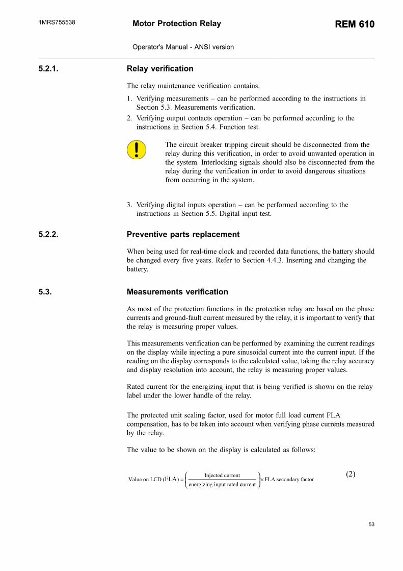
53
5.2.1. Relay verification
The relay maintenance verification contains:
1. Verifying measurements – can be performed according to the instructions inSection 5.3. Measurements verification.
2. Verifying output contacts operation – can be performed according to theinstructions in Section 5.4. Function test.
The circuit breaker tripping circuit should be disconnected from therelay during this verification, in order to avoid unwanted operation inthe system. Interlocking signals should also be disconnected from therelay during the verification in order to avoid dangerous situationsfrom occurring in the system.
3. Verifying digital inputs operation – can be performed according to theinstructions in Section 5.5. Digital input test.
5.2.2. Preventive parts replacement
When being used for real-time clock and recorded data functions, the battery shouldbe changed every five years. Refer to Section 4.4.3. Inserting and changing thebattery.
5.3. Measurements verification
As most of the protection functions in the protection relay are based on the phasecurrents and ground-fault current measured by the relay, it is important to verify thatthe relay is measuring proper values.
This measurements verification can be performed by examining the current readingson the display while injecting a pure sinusoidal current into the current input. If thereading on the display corresponds to the calculated value, taking the relay accuracyand display resolution into account, the relay is measuring proper values.
Rated current for the energizing input that is being verified is shown on the relaylabel under the lower handle of the relay.
The protected unit scaling factor, used for motor full load current FLAcompensation, has to be taken into account when verifying phase currents measuredby the relay.
The value to be shown on the display is calculated as follows:
Value on LCD (Injected current
energizing input rated FLA) =
ccurrentFLA secondary factor
×(2)
Motor Protection Relay
Operator's Manual - ANSI version
REM 610REM 6101MRS755538

When verifying the ground-fault current measured by the relay, the value to beshown on the display is calculated as follows:
Value on LCD Injected currentenergizing input rated c
CT%( ) =uurrent
×100%
(3)
5.4. Function test
This section describes how the signal routing from protection functions to, andoperation of, the output contacts in the relay can be tested.
The internal signals are routed to the output contacts according to the SGR switchgroups.
The test mode is accessible via FUNCTION TEST/DI under CONFIGURATION inthe HMI menu. In the test mode, all internal signals from the different protectionelements can be activated one by one, the self-supervision included.
1. Press an arrow button to access the main menu.
2. Use or to select CONFIGURATION in the main menu and press . Thecursor is at the first menu item, FUNCTION TEST/DI. Press again to enterthe test menu.
3. The cursor is at the first parameter, FUNC.TEST. Press to enter the test modeand give the password if required.
4. Select the wanted signal with or and press to activate the signal. Thesignal remains active for as long as you press .
5. Repeat the previous step to test other signals.
6. To exit the test mode, press .
7. Press again to return the display to the idle mode.
The table below shows the activation order and the corresponding flashing digitwhen a signal is being tested.
Table 5.4.-1 Function test
Number Function
1 Alarm of element 49
2 Trip of element 49
3 Pickup of element 48/14
4 Trip of element 48/14
5 Pickup of element 50P
6 Trip of element 50P
7 Pickup of element 37
8 Trip of element 37
9 Pickup of element 51N
10 Trip of element 51N
11 Pickup of element 46
54
REM 610REM 610 Motor Protection Relay
Operator's Manual - ANSI version
1MRS755538

55
Table 5.4.-1 Function test (Continued)
Number Function
12 Trip of element 46
13 Trip of element 46R
14 Motor start up
15 External trip
16 Alarm of element 49/38-1
17 Trip of element 49/38-1
18 Alarm of element 49/38-2
19 Trip of element 49/38-2
0 IRF
It is also possible to test the output contacts via serial communicationby using the O parameters.
5.5. Digital input test
This section describes how the availability of signals connected to the digital inputscan be tested.
To monitor the status of the digital inputs, navigate in the HMI menu as follows:
1. Press an arrow button to access the main menu.
2. Use or to select CONFIGURATION in the main menu and press . Thecursor is at the first menu item, FUNCTION TEST/DI. Press again to enterthe test menu.
3. Use or to select DI STATUS and press to see the status of DI1.
4. Use and to monitor the state of the other four digital inputs.
5. Press to return the display to the idle mode.
It is also possible to read the state of the digital inputs via serialcommunication.
5.6. Testing protection functions
The short-circuit and ground-fault protection functions in the relay can be testedwith the setting values used during normal operation. If other settings are usedduring testing, make sure that the original settings are re-entered after the test iscompleted.
The test is performed as a secondary test, by injecting current to the currentenergizing inputs. To enable secondary testing without accidentally blocking otherrelays or tripping circuit breakers in the system, the relay has to be disconnected.
Motor Protection Relay
Operator's Manual - ANSI version
REM 610REM 6101MRS755538

For the limited current carrying capacity of the wiring, terminals andmeasuring transformers of the relay, refer to the Technical ReferenceManual.
5.6.1. Testing of the short-circuit protection
If proper 3-phase secondary testing equipment is not available for currentgeneration, the phase unbalance and phase reversal protection functions have to beout of operation during the test.
When calculating the current to be injected into the phase current energizing inputs,the calculation should be done on the basis of the following:
* The rated current, 1 A or 5 A, of the relay energizing input to be tested* The protected unit scaling factor (used for motor full load current compensation)
This gives the current to be injected during the test as follows:
* Injected current (A) = 2.5 x 50P x Rated current of the energizing input xProtected unit scaling factor
To perform the test, inject the current in all three phase current energizing inputs.The output contacts, to which the trip signal is routed from the short-circuitprotection function, should be activated on the expiration of the set operate time ofelement 50P.
5.6.2. Testing of the ground-fault protection
When calculating the current to be injected into the ground-fault current energizinginput, the calculation should be done on the basis of the following:
* The rated current, 1 A or 5 A, of the relay energizing input to be tested
This gives the current to be injected during the test as follows:
* Injected current (A) = 2.5 x 51N x Rated current of energizing input
To perform the test, inject the current in the ground-fault current energizing input.The output contacts, to which the trip signal has been routed from the ground-faultprotection element, should be activated on the expiration of the set operate time ofelement 51N.
56
REM 610REM 610 Motor Protection Relay
Operator's Manual - ANSI version
1MRS755538
57
6. Spare parts
6.1. Plug-in unit
The relay’s construction allows a spare part in form of a plug-in unit. The outagetime can therefore be reduced to a minimum in case the relay should fail.
In case of malfunction, please consult your relay supplier.
The spare plug-in unit to be used for a certain relay is suitable if at least the first 10characters in the order number are identical with those in the order number of thecase.
To obtain identical functionality to those of the original product, allcharacters in the order number, except for those indicating a spare part,should match the ones in the order number of the case.
The relay features a built-in mechanical coding system.. This helps to preventdangerous situations from arising in case a non-suitable plug-in unit is fitted into arelay case.
Forcing a non-suitable plug-in unit into a case breaks the relay and maycause dangerous situations.
The plug-in unit is calibrated as a whole to achieve the best possible operationaccuracy and individual pieces of it should not be removed.
If the faulty plug-in unit is subject to guarantee and the fault is caused undercircumstances covered by the warranty conditions, it should be returned for repair.
Ordering of spare parts is done by using the same ordering system as for ordering anew relay.
6.2. Battery
The battery for real-time clock and non-volatile memory can be purchased in storesspecialized in electronic components.
Recommended battery manufacturers and types are:
* Panasonic of type BR20321)
* Rayovac of type BR20321)
Motor Protection Relay
Operator's Manual - ANSI version
REM 610REM 6101MRS755538
1) Batteries of the recommended lithium BR-types cannot be recharged.

58

59
7. RepairIf the relay fails in operation or if the operating values differ remarkably from thespecified values, the relay is to be given a proper service.
All major measures involving overhaul of electronics are to be takenby the manufacturer.
Contact the manufacturer or the nearest representative for further information onchecking, service and re-calibration of the relay.
When contacting ABB for ordering repair services, give a descriptionof the fault and state the fault code, if applicable.
Motor Protection Relay
Operator's Manual - ANSI version
REM 610REM 6101MRS755538

60

61
8. Ordering informationFor ordering information, refer to the Technical Reference Manual.
Motor Protection Relay
Operator's Manual - ANSI version
REM 610REM 6101MRS755538

62
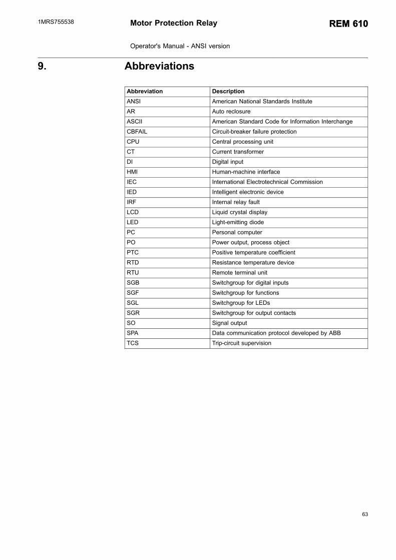
63
9. Abbreviations
Abbreviation Description
ANSI American National Standards Institute
AR Auto reclosure
ASCII American Standard Code for Information Interchange
CBFAIL Circuit-breaker failure protection
CPU Central processing unit
CT Current transformer
DI Digital input
HMI Human-machine interface
IEC International Electrotechnical Commission
IED Intelligent electronic device
IRF Internal relay fault
LCD Liquid crystal display
LED Light-emitting diode
PC Personal computer
PO Power output, process object
PTC Positive temperature coefficient
RTD Resistance temperature device
RTU Remote terminal unit
SGB Switchgroup for digital inputs
SGF Switchgroup for functions
SGL Switchgroup for LEDs
SGR Switchgroup for output contacts
SO Signal output
SPA Data communication protocol developed by ABB
TCS Trip-circuit supervision
Motor Protection Relay
Operator's Manual - ANSI version
REM 610REM 6101MRS755538


ABB OyDistribution AutomationP.O. Box 699FI-65101 VaasaFINLAND+358 10 2211+358 10 224 1080www.abb.com/substationautomation
1MRS755538
EN
1/2007