reliable and secure surveillance, communications and ...jain/papers/ftp/aerosp18.pdf · phone: +34...
TRANSCRIPT

1
Reliable and Secure Surveillance, Communications and
Navigation (RSCAN) for Unmanned Air Systems (UAS) in
Controlled Airspace Denise S. Ponchak
NASA Glenn Research Center 21000 Brookpark Rd. MS 54-1
Cleveland, OH 44135 [email protected]
Fred L. Templin The Boeing Company
P.O. Box 3707 MC 42-59 Seattle, WA 98124
Phone: 425-373-2829 [email protected]
Greg Sheffield The Boeing Company
P.O. Box 516 MC S064-2374 St Louis, MO 63166-0516
Phone: 314-302-7543 [email protected]
Pedro Taboso The Boeing Company
Avenida Sur del Aeropuerto de Barajas, 38
28042 - Madrid; Spain Phone: +34 91 768 8451
Raj Jain Washington University in St. Louis
Saint Louis, MO 63130 Phone: +1 314-322-8092
Abstract—The aviation industry faces a rapidly-emerging need
for integrating Unmanned Air Systems (UAS) into the national
airspace (NAS). This trend will present challenging questions
for the safe operation of UAS in controlled and uncontrolled
airspaces based on new Communications, Navigation and
Surveillance (CNS) technologies. For example, can wireless
communications data links provide the necessary capacity for
accommodating ever increasing numbers of UAS worldwide?
Does the communications network provide ample Internet
Protocol (IP) address space to allow Air Traffic Control (ATC)
to securely address each UAS? Can navigation and
surveillance approaches assure safe route planning and safe
separation of vehicles even in crowded skies?
Under NASA contract NNA16BD84C, Boeing is developing an
integrated CNS architecture to enable UAS operations in the
NAS. Revolutionary and advanced CNS alternatives are
needed to support UAS operations at all altitudes and in all
airspaces, including both controlled and uncontrolled. These
CNS alternatives must be reliable, redundant, always
available, cyber-secure, and affordable for all types of vehicles
including small UAS to large transport category aircraft. Our
approach considers CNS requirements that address the range
of UAS missions where they will be most beneficial and cost-
effective.
A cybersecure future UAS CNS architecture is needed to
support the NASA vision for an Unmanned Air Traffic
Management (UTM) system in uncontrolled airspace and a
cooperative operation of manned and unmanned aircraft in the
controlled global Air Traffic Management (ATM) system. The
architecture must, therefore, support always-available and
cyber secure operations. This paper presents UAS CNS
architecture concepts for large UAS operating in the ATM
system in controlled airspace. Future companion works will
consider small UAS operating in the UTM system in
uncontrolled airspace.
TABLE OF CONTENTS
1. INTRODUCTION ....................................................... 1
2. COMMUNICATIONS - NETWORKS .......................... 2
3. COMMUNICATIONS – DATA LINKS ........................ 5
4. NAVIGATION............................................................ 6
5. SURVEILLANCE ....................................................... 8
6. SUMMARY .............................................................. 11
ACKNOWLEDGEMENTS ............................................ 11 REFERENCES ............................................................. 11
1. INTRODUCTION
This study considers new architectural concepts for the safe
operation of Unmanned Air Systems (UAS) in controlled
airspace (i.e., airspace categories A/B/C/D/E). The
significant implication of this prospect is that UAS will
need to share the same airspace as for manned aviation. This
will require revolutionary new architectural approaches to
Communications, Navigation and Surveillance (CNS) to
ensure that UAS can be integrated safely into worldwide Air
Traffic Management (ATM) system.
The tremendous growth of UAS in air traffic is anticipated
to put a strain on airspace capacity and airport resources. To
mitigate the growth, a new architecture will be required to
take advantage of emerging CNS technologies. To
implement the improvements, the air traffic system requires
significant upgrades to increase system capacity and flight
efficiency while continuing to meet flight safety standards.
The air traffic CNS architecture supporting the growing
number of UAS platforms in the NAS will require new
integrated solutions onboard and additional enterprise CNS
systems functionality.
eprint2018 IEEE Aerospace Conference, Big Sky, MT
`

2
Figure 1 shows a notional CNS architecture to support the
integration of new technologies onboard each UAS platform
and the integration of advancements in existing enterprise
systems.
Navigation augmentations and surveillance information will
be integrated with the communications network and data
link services so that UAS can operate safely in controlled
airspace in cooperation with manned aviation in the ATM
system. Data communications will further provide the
critical infrastructure for command and control (C2),
situation awareness (SA), navigation and surveillance.
Therefore, each element is an interdependent component of
the integrated CNS architecture much in the same way that
the engine, transmission, chassis, body and wheels are all
interdependent components of an automobile. In the
following sections, we discuss the constituent elements of
the proposed integrated UAS CNS architecture in further
detail.
2. COMMUNICATIONS - NETWORKS
Introduction
Unmanned Aircraft (UAs) operating in controlled airspace
will come under the same ATM jurisdiction as for manned
aviation. These UAs will occupy Class A/B/C/D/E airspace
such that their operations will be in non-segregated airspace
where manned aircraft also operate. This means that the
UAS will require a robust and highly-available networked
communications system for Air Traffic Controllers (ATC)
and Airline Operations Controllers (AOC) to issue ATM
directives at any time and with high reliability.
Where manned aviation differs from UAS operations is that
the pilot is on the ground and not on board the aircraft. This
means that there will be a communications profile triad in
which the ATC/AOC issues directives to the ground pilot,
while the ground pilot issues Control and Non-Payload
Communication (CNPC) directives to the UA. For current
ATM systems in manned aviation, primary communications
are through analog voice with data link short text messaging
as a secondary facility. Therefore, ATC/AOC must be able
to communicate with the ground pilot the same as for
manned aviation, and the ground pilot must act on the
ATC/AOC directives by appropriately directing the UA.
Figure 2 - UA/Pilot/ATC Communications Triad
This UAS communications paradigm (Figure 2) has
parallels to the way current-day Department of Defense
(DoD) operations of UAS are coordinated. Ground pilots in
the continental United States control UAs operating in
overseas theaters of operation. The ground pilot’s CNPC
workstation has a direct uplink connection to the satellite
system which then has a direct downlink connection to the
UA, with perhaps one or more relay satellites in the path.
Furthermore, there must be a separate secured voice and/or
data coordination channel for mission commanders to direct
the pilot.
The ground pilot could be located at any physically-secured
location worldwide from which secured UA data link
connections and secured ATM coordination channels are
available. It is also possible to conceive of scenarios where a
Figure 1 - Combined UAS CNS Architectural Framework
3
single UA is handed off between multiple ground pilots
during the course of the flight.
While current-day ATM communications still rely on voice
as a primary for both manned and unmanned aviation, the
International Civil Aviation Organization (ICAO) is actively
working toward a data communications system known as
the Aeronautical Telecommunications Network (ATN) with
Internet Protocol Services (ATN/IPS) [1]. This system is
planned to support data communications as the primary
service, with voice as a backup service beginning in the
2025 and beyond timeframe. In the ICAO vision, a
worldwide ATM internetworking service based on Internet
Protocol, version 6 (IPv6) messaging will be made
available. This system is one and the same as that
anticipated for future operations of UAS in controlled
airspace and is the subject for the rest of this section.
ATN/IPS Overview
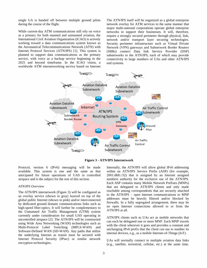
The ATN/IPS internetwork (Figure 3) will be configured as
an overlay service (shown in gray) layered on top of the
global public Internet (shown in pink) and/or interconnected
by dedicated ground domain communications links such as
high-speed fiber-optics. It will further be complementary to
the Unmanned Air Traffic Management (UTM) system
currently under consideration for small UAS operating in
uncontrolled airspace [2]. The ATN/IPS will be constructed
using Wide Area Networking (WAN) technologies such as
Multi-Protocol Label Switching (MPLS-WAN) and
Software-Defined WAN (SD-WAN). Any paths that utilize
the underlying Internet as transit must be secured with
Internet Protocol Security (IPsec) or similar network
encryption technologies.
The ATN/IPS itself will be organized as a global enterprise
network overlay for ATM services in the same manner that
major multi-national corporations operate global enterprise
networks to support their businesses. It will, therefore,
require a strongly secured perimeter through physical, link,
network and/or transport layer securing technologies.
Security perimeter infrastructure such as Virtual Private
Network (VPN) gateways and Subnetwork Border Routers
(SBRs) connect Data link Service Provider (DSP)
subnetworks to the ATN/IPS; each of which may provide
connectivity to large numbers of UAs and other ATN/IPS
end systems.
Internally, the ATN/IPS will allow global IPv6 addressing
within an ATN/IPS Service Prefix (ASP) (for example,
2001:db8::/32) that is assigned by an Internet assigned
numbers authority for the exclusive use of the ATN/IPS.
Each ASP contains many Mobile Network Prefixes (MNPs)
that are delegated to ATN/IPS clients and only made
reachable among correspondents that are securely attached
to the ATN/IPS – open Internet communications to MNP
addresses must be heavily filtered and/or blocked by
firewalls. In a fully segregated arrangement, there may be
no open Internet connections allowed to or from the
ATN/IPS at all.
ATN/IPS clients such as UAs act as mobile networks that
can each be delegated one or more MNP. Each MNP travels
with the client wherever it goes and provides a constant and
unchanging IPv6 prefix that the client can use to number its
internal devices, e.g., as a mobile Internet-of-Things (IoT).
UAs will normally connect to multiple aviation data links
(e.g., satellite, terrestrial, cellular, etc.) at the same time.
Figure 3 - ATN/IPS Internetwork

4
This multilink arrangement affords the best reliability, cost,
performance and quality of service parameters throughout
the UA’s various phases of flight. In the ATN/IPS design,
the multilink capability is also fundamentally tied to the
concept of multihoming where the UA can be registered
with multiple service provider networks at the same time.
This arrangement provides greater reliability since the UA
will have multiple data links to choose from
ATN/IPS Internetworking Architecture
Figure 4 shows the ATN/IPS multilink internetworking
architecture. The service consists of the ATN/IPS physically
connected underlay and with the Asymmetric Extended
Route Optimization (AERO) [3] service as an overlay. The
AERO overlay is responsible for mobility, multihoming,
security, traffic engineering and quality-of-service based
routing.
Figure 4 – ATN/IPS Internetworking Architecture
In this architecture, AERO Servers form the boundary of the
ATN/IPS global enterprise network and all communications
within the ATN/IPS are carried through encapsulation-based
tunneling across the underlying internetwork. AERO
Servers connect AERO Clients to the ATN/IPS (shown here
as manned and unmanned aircraft) and can forward packets
to destinations via AERO Relays (shown here in the
ATN/IPS core).
Aircraft connect to the ATN/IPS via data links that may be
terminated in a secured data link service provider network
or open to the global public Internet. In the former case, data
link service provider SBRs provide a proxy connectivity
service to the Clients, while in the latter case the Clients
maintain their own mobile VPNs.
From the interior viewpoint of the ATN/IPS global
enterprise network, all AERO Servers present identical
Client services, and Clients can associate with one or more
Servers that are nearby. Each AERO Server provides Client-
directed Quality of Service (QoS) mappings and also
provides priority and/or weight metrics so that AERO
Relays can make forwarding decisions.
From an exterior viewpoint, each subnetwork model has its
own manner of offering secured services to mobile clients,
with each model having application for various ATN/IPS
use cases. For example, large UAs operating over tightly-
managed DSP link types will likely use the closed
subnetwork model. ATN/IPS correspondents on the open
Internet will use the non-subnetwork model and connect
directly to AERO Servers via a mobile VPN.
In the AERO model, AERO Servers and Relays participate
in a private Border Gateway Protocol (BGP) instance that
tracks all of the MNPs currently active in the ATN/IPS
routing system. AERO Relays maintain a core Autonomous
System (AS), while AERO Servers form stub ASes. When a
source AERO Server has a packet to send, it sends the
packet immediately via a default route to an AERO Relay
which then forwards it toward the highest-priority target
AERO Server. The source AERO Server can then initiate a
route optimization procedure to discover one or more targets
that it can send subsequent packets to without having to
continue sending them through the dogleg path via the
AERO Relays. This route optimization can be deferred until
the direct path between the source and target AERO Servers
can be tested so that the risk of black-holing along the path
is eliminated.
In the AERO model, route optimization is through control
message signaling after initial packets are successfully sent
via the default route. An extremely important consideration,
however, is whether a route optimized path can be
considered usable before being tested. Instead of making a
leap of faith, the source AERO Server tests the route
optimized path first while data packets are allowed to
continue to flow through a longer path that is known to
work. The longer path can be considered more reliable since
it travels over the same paths where BGP Transmission
Control Protocol (TCP) session keepalives maintain
reachability.
The route-optimized path between the source and target
AERO Servers can fail at some time after the path was first
tested. This means that some form of unreachability
detection is required that can quickly detect the path failure
with a minimum amount of packet loss. Furthermore, if an
ATN/IPS end system moves from a first AERO Server to a
second Server, any peers with a route optimization pointing
to the first AERO Server will have to be informed that the
route is no longer valid. If each AERO Server remembers
the peers to which it previously sent route optimization
messages, it can proactively send updates to invalidate the
previous route optimizations. If the source AERO Server
has not received an update and continues to send packets to
the target, however, the target can reactively send
“Destination Unreachable” messages while dropping the
packets. From a reliability standpoint, therefore, it is very
important that AERO Servers send proactive updates before
any data packets arrive that would trigger a reactive
Destination Unreachable.

5
3. COMMUNICATIONS – DATA LINKS
Current Data links for Controlled Airspace
Currently, the aeronautical standard bodies are discussing
two new data links for unmanned aircraft systems. These are
Aeronautical Mobile Airport Communication System
(AeroMACS) and L-band digital aeronautical
communications system, type 1 (LDACS1). These are
briefly described below along with a next-generation
satellite system before discussing the ideas for the next
generation.
AeroMACS - AeroMACS is the data link technology
developed by RTCA SC-223 for airport surface
communications. AeroMACS operates in the Aeronautical
Mobile (R) Service (AM(R)S) allocation in the C band.
Specifically, a 55 MHz band (5.095-5.150 GHz) is used and
divided into eleven 5-MHz channels. Each channel uses
orthogonal frequency division modulation (OFDM) using
512 subcarriers with an inter-carrier spacing of
approximately 10 kHz.
LDACS1 - LDACS1 is leading proposed alternatives for
communications during in-flight phase (Mission category
D2). It uses OFDM in the L band. Since L Band is lower in
frequency than C band used in AeroMACS, it can reach
farther distances. It uses 50 subcarriers in a 498 kHz
frequency band. The sub-carrier spacing of 9.76 kHz in L-
DACS1 is similar to that of WiMAX. For an in-depth
analysis of L-DACS1, please see our papers [4][5][6].
Satellite Systems - Currently Inmarsat and Iridium-Next are
cornerstones of the long-term plan for data communications
for manned aircraft and we should expect the same links for
UAS data comms in controlled airspace.
Another promising next-generation system is the SpaceX,
which promises the lowest latency and highest data rate of
all systems till to date. SpaceX is a collaboration of SpaceX
corporation and Google. It plans to put 4000 Low-Earth
Orbit (LEO) satellites by 2020. Using a 650 km orbit and
inter-satellite links, it plans to offer a latency of 20 ms. With
50 Gbps per satellite, the total throughput could over 200
Tbps. Assuming 50 million customers, the throughput per
customer will be 4 Mbps. This should be ideal for UAS
communication.
Enhancements to ATM Data links
The key metrics for UAS data links are peak data rate, per
user data rates, and energy efficiency. Figure 5 shows the
desired enhancements in these metrics.
Most forecasts of UAs in the controlled airspaces are based
on those of the current manned aircraft and the increase in
the number of total aircrafts even after ten years is
forecasted to be less than 5x [7]. This may be an under-
forecast since most of the applications of UAs are not in the
same area as the manned aircrafts but in applications that
currently use cars and trucks.
Given this uncertainty, we believe ideas that improve the
data link performance by an order magnitude would be
reasonable. Some of this increase will come from an
increased spectrum that is being discussed in various
international standards bodies. The remaining increase will
have to come from increased spectral efficiency.
Similarly, assuming a 5-fold increase in UA density, per UA
data rate will go up by a factor of 2. This is in line with
RTCA forecasts of data rate requirements for UA data links
[8].
The next generation of ATM data links can benefit from
some of the new Radio Multiplexing techniques that are
being developed for the next generation of data
communications.
Figure 5 - Goals for Next Generation ATM Data Links
New Radio Multiplexing Technologies
Both LDACS-1 and AeroMACS use OFDM. Almost all
wireless technologies developed in 2000-2010 use OFDM.
OFDM is now known to have several problems [9] that
newer proposals are aiming to solve. The problems with
OFDM are:
1. Spectrum Overflow: In order to guarantee
orthogonality, each subcarrier should have a zero
power at the neighboring subcarriers. This results
in a power ripple and there is a significant
spectrum overflow beyond the spectrum used by
the subcarriers. This is overcome in OFDM by
having a guard band.
2. Same Subcarrier Spacing: OFDM requires that
all subcarriers be equally spaced. To avoid a noisy
frequency, an integral number of subcarriers need
to be either not used or used at a low rate
modulation.
3. Same Symbol Size: All subcarriers need to use the
same symbol size and cyclic prefix.
Peak data rate
Per UAS
data rate
UAS Density/km2
Spectral Efficiency
Spectrum
Energy Efficiency
Current
ATM
Next Gen
ATM10X
2X
5X 2X
5X
2X
6
4. Time Synchronization: In OFDMA, all users
should time synchronize in the uplink otherwise
they will interfere with each other.
Newer technologies that overcome these problems are now
being proposed. Two of these techniques are discussed in
this section.
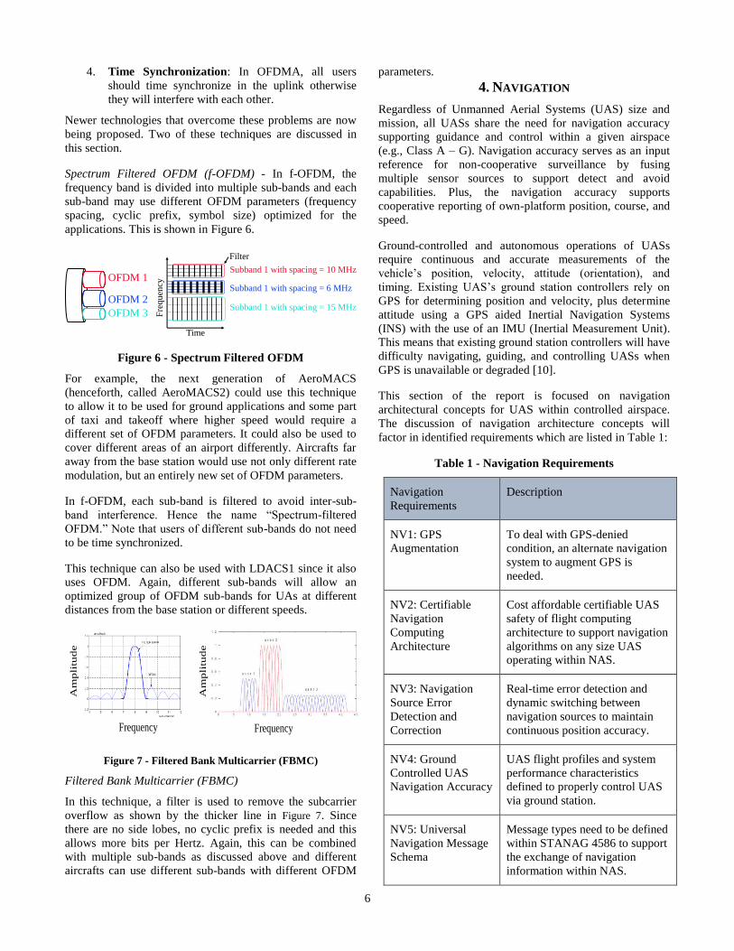
Spectrum Filtered OFDM (f-OFDM) - In f-OFDM, the
frequency band is divided into multiple sub-bands and each
sub-band may use different OFDM parameters (frequency
spacing, cyclic prefix, symbol size) optimized for the
applications. This is shown in Figure 6.
Figure 6 - Spectrum Filtered OFDM
For example, the next generation of AeroMACS
(henceforth, called AeroMACS2) could use this technique
to allow it to be used for ground applications and some part
of taxi and takeoff where higher speed would require a
different set of OFDM parameters. It could also be used to
cover different areas of an airport differently. Aircrafts far
away from the base station would use not only different rate
modulation, but an entirely new set of OFDM parameters.
In f-OFDM, each sub-band is filtered to avoid inter-sub-
band interference. Hence the name “Spectrum-filtered
OFDM.” Note that users of different sub-bands do not need
to be time synchronized.
This technique can also be used with LDACS1 since it also
uses OFDM. Again, different sub-bands will allow an
optimized group of OFDM sub-bands for UAs at different
distances from the base station or different speeds.
Figure 7 - Filtered Bank Multicarrier (FBMC)
Filtered Bank Multicarrier (FBMC)
In this technique, a filter is used to remove the subcarrier
overflow as shown by the thicker line in Figure 7. Since
there are no side lobes, no cyclic prefix is needed and this
allows more bits per Hertz. Again, this can be combined
with multiple sub-bands as discussed above and different
aircrafts can use different sub-bands with different OFDM
parameters.
4. NAVIGATION
Regardless of Unmanned Aerial Systems (UAS) size and
mission, all UASs share the need for navigation accuracy
supporting guidance and control within a given airspace
(e.g., Class A – G). Navigation accuracy serves as an input
reference for non-cooperative surveillance by fusing
multiple sensor sources to support detect and avoid
capabilities. Plus, the navigation accuracy supports
cooperative reporting of own-platform position, course, and
speed.
Ground-controlled and autonomous operations of UASs
require continuous and accurate measurements of the
vehicle’s position, velocity, attitude (orientation), and
timing. Existing UAS’s ground station controllers rely on
GPS for determining position and velocity, plus determine
attitude using a GPS aided Inertial Navigation Systems
(INS) with the use of an IMU (Inertial Measurement Unit).
This means that existing ground station controllers will have
difficulty navigating, guiding, and controlling UASs when
GPS is unavailable or degraded [10].
This section of the report is focused on navigation
architectural concepts for UAS within controlled airspace.
The discussion of navigation architecture concepts will
factor in identified requirements which are listed in Table 1:
Table 1 - Navigation Requirements
Navigation
Requirements
Description
NV1: GPS
Augmentation
To deal with GPS-denied
condition, an alternate navigation
system to augment GPS is
needed.
NV2: Certifiable
Navigation
Computing
Architecture
Cost affordable certifiable UAS
safety of flight computing
architecture to support navigation
algorithms on any size UAS
operating within NAS.
NV3: Navigation
Source Error
Detection and
Correction
Real-time error detection and
dynamic switching between
navigation sources to maintain
continuous position accuracy.
NV4: Ground
Controlled UAS
Navigation Accuracy
UAS flight profiles and system
performance characteristics
defined to properly control UAS
via ground station.
NV5: Universal
Navigation Message
Schema
Message types need to be defined
within STANAG 4586 to support
the exchange of navigation
information within NAS.
Time
Fre
qu
ency
Subband 1 with spacing = 10 MHz
Subband 1 with spacing = 6 MHz
Subband 1 with spacing = 15 MHz
OFDM 1
OFDM 2
OFDM 3
Filter
Frequency
Am
pli
tud
e
Am
pli
tud
e
Frequency

7
NV6: BLOS
Navigation Accuracy
To compensate for increase
latency in command and control
of UAS in BLOS operations,
assured navigation accuracy is
required to allow for increased
autonomous functions.
NV7: Autonomous
Landing Navigation
Accuracy
Autonomous UAS landing on a
stationary landing pads or
runways will require UAS sensor
capabilities to augment the
human similar to manned aircraft
during required visual phases of
landing.
Onboard UAS Architectural Framework
The onboard UAS architecture concept is approached with
the consideration that “no one stand-alone technology” is
envisioned to augment GPS for all customers and all
operational conditions. Therefore, the Boeing team is
recommending an architectural framework which can
evolve and support a wide range of alternative navigation
sources to address the requirement “NV1: GPS
Augmentation”. Figure 8 shows a recommended navigation
architecture framework to exploit navigation technologies
and techniques for augmenting GPS:
IMA Partitioning
Boeing recommends utilizing Integrated Modular Avionics
(IMA) techniques supporting onboard navigation integration
to reduce cost, weight, space, and power consumption. This
architectural concept would be useful for all airborne
platforms to move away from the traditional integration
with line replaceable units (LRU) to software partitions
within a consolidated hardware package, such as System on
Chip (SoC).
This architectural consideration is supportive of modular
open architecture for ease of integration of a vast number of
sensors either dedicated to navigation or leveraged from
surveillance and/or communications sources. ARINC 653
can support mix criticality of applications from non-
essential to flight safety critical within the same computing
hardware which addresses the requirement NV2: Certifiable
Navigation Computing Architecture.”
Integration Perspectives
GPS signals alone are extremely weak due to high
frequency and useless in certain environments, such as low
urban and deep canyon operations. To address requirement
“NV3: Navigation Source Error Detection and Correction”
during GPS-denied or degraded conditions, the use of both
recommended architectural framework and the IMA
computing based on ARINC 653 can provide a means of
real-time navigation error detection and correction. Within
ARINC 653 there are a set of Health Monitoring features
which can be utilized to detect an error with either the GPS
hardware or quality of the measurement. The correction
would then be handled by the ARINC 653 configuration
table which would be defined dependent on the type of
errors expected and types of navigation source alternatives
available.
The recommended architectural framework and the IMA
computing based on ARINC 653 is supportive of all flight
phases of an UAS. For example, navigation algorithms can
be developed within separate partitions supporting “NV4:
Ground Controlled UAS Navigation Accuracy” and “NV6:
BLOS Navigation Accuracy” requirements for different
flight phases accommodating the vast number of UAS
Inertial Nav System
Propagate
Update
IMU,Clock
Feedback
Measurements
GNSS GBAS ILSCOM
RangingSOP
RF Based NavAids
Image Based Nav Aids
GBAS = Ground Based Augmentation System
GNSS = Global Navigational Satellite Systems
SOP = Signals of Opportunity
P, V, A, & T
Reference Database
LIDAR/ LADAR
EO/IR Radar
Figure 8- UAS Navigation Architectural Framework
8
maneuverability (e.g., speed, rate of turns, climb, descent,
etc.) profiles and the varying closed loop command and
control time for Line of Sight (LOS) and Beyond Line of
Sight (BLOS) communications.
For autonomous landing, “NV7: Autonomous Landing
Navigation Accuracy” requirement, the recommended
architectural framework and the IMA computing based on
ARINC 653 are supportive of tightly coupled navigation
algorithms with flight control algorithms. This technical
approach would be very similar to fielded auto-pilot systems
on manned platforms.
As a means to integrate within ATM, the UAS onboard
architectural framework is envisioned to communicate using
an industry approach message schema supporting “NV5:
Universal Navigation Message Schema.” The recommended
schema is based on STANAG 4586 to exchange navigation
information between the UAS and respective ground station.
UAS Navigation Architecture Summary
In summary, the onboard UAS navigation architecture
concept is approached leveraging multiple sources with a
minimalistic addition of equipage with the consideration
that “no one stand-alone technology” will augment GPS in
all flight phases in Class A – E airspace. The proposed
architecture is envisioned to host functions beyond
navigation, such as surveillance, communications, vehicle
management, flight controls, maintenance, etc., with the use
of the IMA computing architecture based on ARINC 653.
The UAS navigation architecture concept is also envisioned
supporting navigation functions by leveraging sensors for
non-cooperative detect and avoid capabilities and signal
characteristics from onboard communications systems.
5. SURVEILLANCE
Introduction
Controlled airspace is defined by a set of requirements in
terms of altitude, proximity to airports, ATC clearances,
avionics, instrumental flight rules, and visual flight rules
[11]. An efficient UAS ATM system requires cooperative
surveillance systems. In particular, dependent cooperative
surveillance systems provide significant benefits including
high precision independent of target distance, transmission
of additional data such as velocity [12]. UAs must
implement methods to autonomously determine their own
positions.
This section of the presents ADS-IP system, a proposal of
cooperative surveillance system able to cope with the
upcoming paradigm of UAS air traffic and to overcome the
limitations of current surveillance systems for controlled
airspace.
The need of UAs of being connected
Although it is possible to carry on completely autonomous
UAs missions, from a safety perspective, it is imperative to
implement such communication means. There shall always
be a pilot responsible for the flight who, in case of
emergency or under any other circumstances, can remotely
take control of the vehicle. An RF-based communication
channel is usually used for this purpose.
Apart from that, it is considered necessary a more accessible
media to enable the monitoring of the UA and to enable
potential interventions over it. The kind of data links
required for these kind of services can be established
through Internet connections.
Why ADS-IP
Traditional surveillance systems are already close to
saturation. Current surveillance systems based on RF
transmissions will not be able to cope with the upcoming
UAS paradigm.
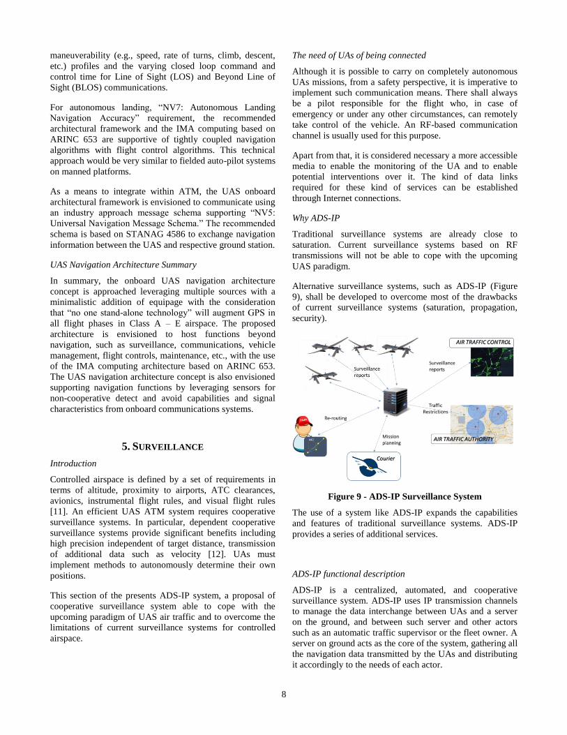
Alternative surveillance systems, such as ADS-IP (Figure
9), shall be developed to overcome most of the drawbacks
of current surveillance systems (saturation, propagation,
security).
Figure 9 - ADS-IP Surveillance System
The use of a system like ADS-IP expands the capabilities
and features of traditional surveillance systems. ADS-IP
provides a series of additional services.
ADS-IP functional description
ADS-IP is a centralized, automated, and cooperative
surveillance system. ADS-IP uses IP transmission channels
to manage the data interchange between UAs and a server
on the ground, and between such server and other actors
such as an automatic traffic supervisor or the fleet owner. A
server on ground acts as the core of the system, gathering all
the navigation data transmitted by the UAs and distributing
it accordingly to the needs of each actor.
9
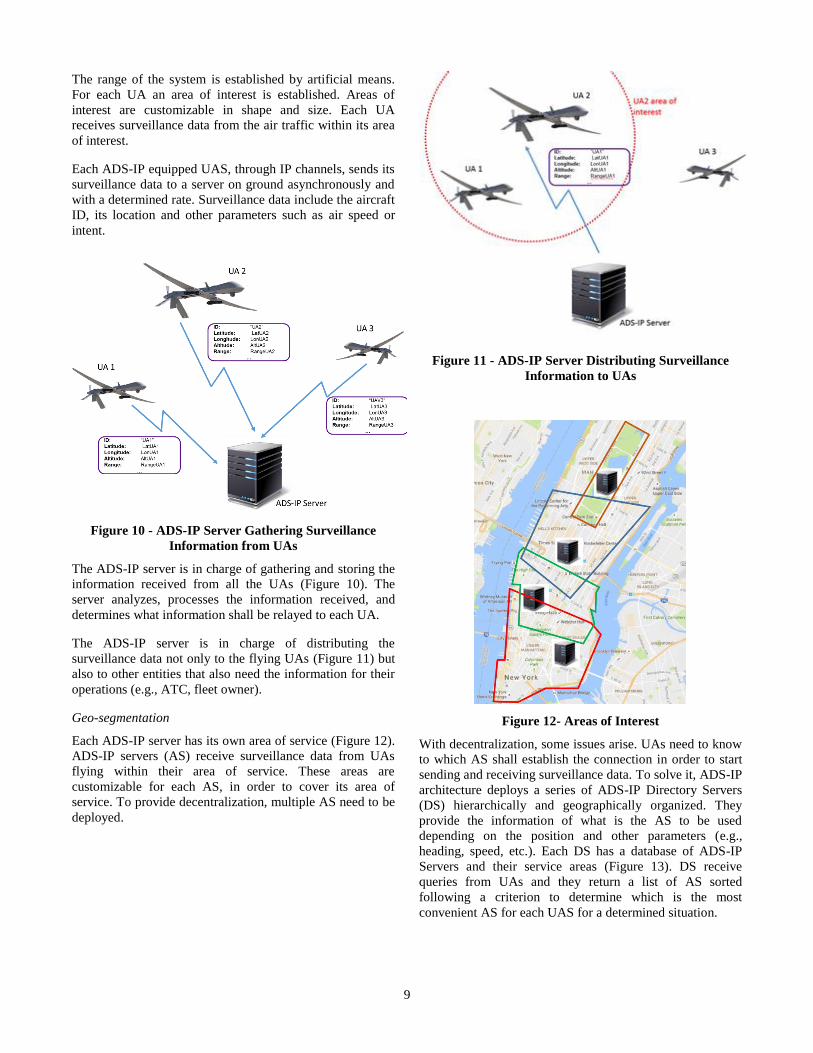
The range of the system is established by artificial means.
For each UA an area of interest is established. Areas of
interest are customizable in shape and size. Each UA
receives surveillance data from the air traffic within its area
of interest.
Each ADS-IP equipped UAS, through IP channels, sends its
surveillance data to a server on ground asynchronously and
with a determined rate. Surveillance data include the aircraft
ID, its location and other parameters such as air speed or
intent.
Figure 10 - ADS-IP Server Gathering Surveillance
Information from UAs
The ADS-IP server is in charge of gathering and storing the
information received from all the UAs (Figure 10). The
server analyzes, processes the information received, and
determines what information shall be relayed to each UA.
The ADS-IP server is in charge of distributing the
surveillance data not only to the flying UAs (Figure 11) but
also to other entities that also need the information for their
operations (e.g., ATC, fleet owner).
Geo-segmentation
Each ADS-IP server has its own area of service (Figure 12).
ADS-IP servers (AS) receive surveillance data from UAs
flying within their area of service. These areas are
customizable for each AS, in order to cover its area of
service. To provide decentralization, multiple AS need to be
deployed.
Figure 11 - ADS-IP Server Distributing Surveillance
Information to UAs
Figure 12- Areas of Interest
With decentralization, some issues arise. UAs need to know
to which AS shall establish the connection in order to start
sending and receiving surveillance data. To solve it, ADS-IP
architecture deploys a series of ADS-IP Directory Servers
(DS) hierarchically and geographically organized. They
provide the information of what is the AS to be used
depending on the position and other parameters (e.g.,
heading, speed, etc.). Each DS has a database of ADS-IP
Servers and their service areas (Figure 13). DS receive
queries from UAs and they return a list of AS sorted
following a criterion to determine which is the most
convenient AS for each UAS for a determined situation.

10
Figure 13 - ADS-IP Directory Service
ADS-IP servers are registered into a specific DS (primary).
Each primary DS replicates the information within its
database over one (or more) secondary DS in order to
enhance the reliability of the ADS-IP system.
UAs are able to query any DS. Queries over DS are
forwarded to the correspondent DS if the location of the UA
belongs to a different DS service area.
The descriptive process of the overall performance of ADS-
IP is as follows:
1. An UA autonomously determines its location.
2. It queries to a DS for a list of ADS-IP servers
within its area.
3. The DS determines a list of usable ADS-IP servers
and provides the UA with it.
4. The UA then establishes a connection with one of
the ADS-IP servers of the list.
Other issues related with the geo-segmentation of ADS-IP
are:
Handovers: To deal with handovers, AS sends an
alert to the UAS when it is close to the boundary of
its area of service. The UAS queries a DS again.
Overlapping areas: It is necessary to establish
coordination mechanisms between overlapping AS.
Services that can be delivered by ADS-IP
This section presents a series of services that can be
provided by ADS-IP:
Surveillance data gathering and broadcast: This
is the main function of the ADS-IP system.
Tracking services: ADS-IP servers deploy data
persistence capabilities which enables ADS-IP to
provide non-real time data tracking services and
analytics to operators, authorities…
Dynamic exclusive/inclusive fly zones: Through
ADS-IP it is possible to create exclusive and
inclusive fly zones.
Cooperative anti-collision systems: ADS-IP
analyzes the tracking of the UAs in real time and
predicts the future location of UAs, so by this mean
it is also possible to predict safety issues.
ADS-IP Security
This section presents how ADS-IP overcomes the main
vulnerabilities of ADS-B [13] and as shown in Table 2.
Table 2 - Threats Addressed by ADS-IP
ADS-IP relies on secure transmission channels. The
communications infrastructure establishes a series of
encrypted VPNs. Thus, eavesdropping will not be feasible.
ADS-IP does not use the 1090MHz frequency band. As the
integral architecture proposed relies on the establishment of
communication channels through different data links, the
risk of a denial of service based on jamming is decreased.
ADS-IP implements authentication mechanisms to avoid
fraudulent injection of messages.
ADS-IP uses acknowledge mechanisms and encryption
techniques to sign the messages; these measures reduce the
risk of successful message injection and message deletion
attacks.
Modes of operation of ADS-IP
ADS-IP implements two different modes of operation,
authenticated and non-authenticated.
An authenticated mode is implemented in order to verify the
identity of the UAs. To operate in this mode, each UA shall
be registered following the procedures established by
regulations. In order to facilitate the registration procedure,
an auto-provisioning system may be implemented. This
mode of operation reinforces the confidentiality, integrity,
authenticity, and non-repudiation dimensions of the ADS-IP
system. On the other hand, an authenticated system presents
some issues. The process of registration might be seen as an
entry barrier by the users of the system. It will be necessary
to define new roles and responsibilities to maintain the
authentication system. Therefore, there shall be developed
and implemented systems to solve the problem of
authenticating UAs over different ADS-IP systems of
different service areas or jurisdictions.
11
An open mode of operation is also possible. In this mode of
operation, both ADS-IP servers and Directory servers are
publicly available and provide surveillance services without
requesting any credentials to the UAs. At first glance, this
mode of operation can be seen as an insecure system. The
system might be vulnerable to spoofing and DoS attacks.
However, there are several countermeasures that can be
applied to minimize these risks. On the other hand, a
surveillance system working in an open mode presents some
interesting benefits. The main one is that a higher number of
UAs might be monitored, raising the safety level of the air
traffic. With this mode of operation, the problems related to
the management of the credentials disappear, reducing the
costs of maintenance and increasing the compatibility
between ADS-IP servers of different owners.
ADS-IP pros and drawbacks
ADS-IP Pros - This section of the document highlights a
series of features of ADS-IP which improve the current
capabilities of current existing surveillance systems in
controlled airspaces.
Global Tracking. One of the main problems of
current surveillance systems is the lack of coverage
outside the operational areas of radar, ADS-B or
multilateration.
Security. ADS-B vulnerabilities are well known as
they have been proved and presented in various
papers available on the public media [14].
Integration of UAS in the airspace. The UAS
industry is growing and it is expected that UAs will
be sharing airspace with commercial air traffic.
Surveillance technologies are needed for a safe
integration of UAs in the airspace without reducing
existing capacity.
ADS-IP Drawbacks - This section presents the identified
limitations of ADS-IP.
Integration with current surveillance systems: When deploying ADS-IP within controlled
airspace, it will be necessary to invest an important
amount of effort in the integration of ADS-IP with
current surveillance systems used by the ATCs to
manage the air traffic.
Cooperative surveillance systems limitations
ADS-IP share some limitations with the rest of cooperative
surveillance systems. There is still a need to develop
surveillance systems to detect, identify, and cope with non-
compliant systems (non-intentional and intentional).
6. SUMMARY
In this document, we propose revolutionary new
architectural concepts for Communications, Navigation and
Surveillance (CNS) of UAS in controlled airspace. The
ideas have implications for standards organization activities
such as in the IEEE, IETF, ICAO and RTCA, and further
build on designs that have been under development in
internal R&D efforts in the authors’ organizations. We
believe that these concepts can help open new opportunities
for the safe operation of UAS in controlled airspace in
cooperation with the Air Traffic Management systems both
within the United States and world-wide.
We see the emergence of a worldwide ATN/IPS service
with networks and data links that can support data
communications for UAS ATM as a key enabler to allow
safe integration of UAS in non-segregated airspace. We
further believe the new concepts in navigation and
surveillance presented here will be instrumental in
maintaining safe operations in cooperation with manned
aviation.
The next phase of our investigation will explore new UAS
CNS architectural concepts for the operation of small UAS
(sUAS) in uncontrolled airspace. These concepts will be in
keeping with the UTM Concept of Operations articulated by
NASA [2] and that is being embraced by the worldwide
UAS community. One of the first questions to be answered
is whether the UTM system will be separate from the
system proposed here for controlled airspace, or will it all be
a single system for both.
Clearly, ATC/AOC workload must be a primary
consideration given that there will be millions of UAS
operating in uncontrolled airspace in the coming years. The
key, therefore, is to again allow the requirements to shape
the architectural solutions we will propose. We believe that
the same concepts developed here for UAS operation in
controlled airspace can be adapted for operation of sUAS in
uncontrolled airspace with the key differences in scale (i.e.,
the numbers of sUAS in operation) as well as vehicle size
weight and power.
ACKNOWLEDGEMENTS
This work is aligned with the NASA Safe Autonomous
Systems Operation (SASO) program under NASA contract
number NNA16BD84C.
REFERENCES
[1] “ICAO 9896 Manual on the Aeronautical
Telecommunication Network (ATN) Using Internet
Protocol Suite (IPS) Standards and Protocols”, Second
Edition 2015.
[2] Kopardekar, P., et al., “Unmanned Aircraft System Traffic
Management (UTM) Concept of Operations”, AIAA
Aviation Technology, Integration, and Operations
Conference, June 2016.

12
[3] Templin, F. “Asymmetric Extended Route Optimization
(AERO)”, draft-templin-aerolink, (work-in-progress),
May 2017.
[4] Raj Jain, Fred L. Templin, "Datalink for Unmanned
Aircraft Systems: Requirements, Challenges and Design
Ideas," AIAA Infotec@Aerospace Conference, Saint
Louis, MO, March 2011,
http://www.cse.wustl.edu/~jain/papers/uas_dl.htm
[5] Raj Jain, Fred L. Templin, Kwong-Sang Yin, "Analysis of
L-Band Digital Aeronautical Communication Systems: L-
DACS1 and L-DACS2," 2011 IEEE Aerospace
Conference, Big Sky, Montana, March 5-12, 2011, pp. 1-
10, http://www.cse.wustl.edu/~jain/papers/ldacs.htm
[6] Raj Jain and F. Templin, "Requirements, Challenges and
Analysis of Alternatives for Wireless Datalinks for
Unmanned Aircraft Systems," IEEE Journal on Selected
Areas in Communications (JSAC) Special Issue on
Communications Challenges and Dynamics for
Unmanned Autonomous Vehicles, Vol. 30, No. 5, June
2012, pp. 852-860,
http://www.cse.wustl.edu/~jain/papers/uas_jsac.htm
[7] RTCA, Operational Services and Environmental
Definition (OSED) for Unmanned Aircraft Systems
(UAS), DO-320, 2010, 236 pp.
[8] RTCA, UAS Command and Control (C2) Data Link
White Paper, WP-2_C2, 2014, 88 pp.
[9] P. Zhu, "5G Enabling Technologies," PIMRC, Sep 2014,
20 slides, http://www.ieee-pimrc.org/2014/2014-09-
03%205G%20Enabling%20Technologies%20PMIRC%2
0Huawei_Final.pdf
[10] Impact and Mitigation of GPS-Unavailability on Small
UAV Navigation, Guidance and Control,
https://core.ac.uk/download/pdf/11432788.pdf
[11] FAA NY/NJ/PHL Airspace Redesign Final
Environmental Impact Statement (FEIS), “Appendix A:
National Airspace System Overview.” July 2007. 5pp.
[12] RTCA, "Minimum Aviation system Performance
Standards for Automatic Dependent Surveillance-
Broadcast (ADS-B)," DO-242A, June 25, 2002, 475 pp.
[13] Martin Strohmeier, et al., “On the Security of the
Automatic Dependent Surveillance-Broadcast Protocol,”
April 15, 2014.
[14] Andrei Costin, Aurelien Francillon. “Ghost in the
Air(Traffic): On insecurity of ADS-B protocol and
practical attacks on ADS-B devices.” Network and
Security Department EURECOM Sophia-Antipolis,
France. Black Hat USA, 2012. 16, 2012.
Biographies
Denise S. Ponchak is Branch Chief
of the Communications
Architectures, Networks and
Systems Branch at the National
Aeronautics and Space
Administration’s (NASA) Glenn
Research Center at Lewis Field in
Cleveland, Ohio. The Branch is
responsible for designing advanced
networking concepts, architectures,
and technologies for aeronautics and space applications.
Prior to becoming Branch Chief, Ms. Ponchak was an
Aeronautical Communications Project Manager focusing on
increasing the National Airspace System’s
telecommunications capability, and a Communications
Research Engineer supporting future satellite-based
communications. She holds a Bachelor’s of Electrical
Engineering and a Master’s of Science in Electrical
Engineering from Cleveland State University in 1983 and
1988 respectively.
Fred Templin is a computer
networking R&D professional with
a focus on Internet protocol and
data link specifications, operating
system networking internals,
networked applications, and
networked platforms. He has in-
depth experience in Internet
networking and security
architectures for unmanned air
systems, civil aviation, tactical
military, space-based systems and enterprise network
applications. Mr. Templin has been an active contributor to
the Internet Engineering Task Force (IETF) since 1999. He
is currently a senior research engineer in Boeing Research
& Technology (BR&T) since May 2005, where he is an
Associate Technical Fellow of The Boeing Company.
Greg L. Sheffield is a Senior
Research Engineer in the Boeing
Research & technology (BR&T)
Avionics Systems Technology group.
Greg's experience includes over 26
years working with commercial and
defense communications,
navigation, and surveillance
technologies and products. He has
contributed to a number of IEEE,
RTCA, ARINC, and SAE standards.
Most noted is his contributions related to digital
communications using ACARS, second-generation TCAS
combined with ADS-B, Navigation solutions in denied or
degraded environments, and affordable open avionics
architectures solutions. Greg is a retired Navy Flight
Officer and holds BSEE, BSCS, SysEngMS, and MBA
degrees. He lives and works in the St Louis, MO area.
13
Pedro Taboso is a
Telecommunication Engineer (5
year-degree, Polytechnic University
of Madrid) with a background in IT
systems and a proven professional
and hands-on experience within
Cyber Defence and Information
Assurance fields. Pedro holds
relevant security trainings and
certifications such as CISA
(Certified Information Security Auditor), ITILv3 and SANS
508 (Computer Forensics). He has a strong background on
Information Security projects (penetration testing, ethical
hacking, security architecture design, risk analysis…).
During the last four years, he has been working on
applications development for “Security- Over- CNS
systems” projects, defining and developing new
Surveillance systems for both manned and unmanned
aircraft.
Raj Jain is a Fellow of IEEE, ACM,
and AAAS. He is a winner of 2017
ACM SIGCOMM Life-Time
Achievement Award, 2015 A.A.
Michelson Award. Dr. Jain is
currently the Barbara J. and
Jerome R. Cox, Jr., Professor of
Computer Science and Engineering
at Washington University in St.
Louis. Previously, he was one of the
Co-founders of Nayna Networks,
Inc – a next-generation
telecommunications systems company in San Jose, CA. He
was a Senior Consulting Engineer at Digital Equipment
Corporation in Littleton, Mass and then a professor of
Computer and Information Sciences at Ohio State
University in Columbus, Ohio.