reiiabilitation of steel bridges in sri lanka · pdf filereiiabilitation of steel bridges in...
TRANSCRIPT
REIIABILITATION OF STEEL BRIDGES IN SRI LANKA Eng.B.Y.D.N.Chandrasiri* And Eng. Dr. M.T.R.Jayasinghc**
• Deputy Director, Maintenance Management & Construction Division. Road Development
Authority. •• Senior lecturer, Department ofC1v1l Engineering. University of Moratuwa
ABSTRACT
Nearly one half of the approximately 3700 highway bridges on A and B class roads of Sri
Lanka arc more than 50 years o ld . About 60% of the total bridges have a width of less than 8.0
m; out of these 689 arc s teel bridges. Most of these steel bridges would need upgrading 111
future to cater for present day traffic needs. The upgrading option can be either replacement or
rehabilitation. Rehabilitation can be quite altraclive if it can have cost savings and fewer
disturbances to traffic. In this paper, various options available for rehabilitation of steel
bridges arc reviewed. The methods better suited for Sri Lanka arc Identified. The criteriato
determine the economic feasibility arc highlighted. The anticipated cost of replacement is
determined to indicate the importance of adopting rehabilitation whenever cost effective.
INTRODUCTION
The majority of steel bridges in Sri Lanka were built in the last 50 to 60 years.
Out of a total of 3700 highway bridges (Bridge Database, RDA) on A and 8
class roads (Figure l), approximately 60 % of the bridges have a width less
than 8.0m. For the present day traffic conditions, a deck width of about 8.0m
can be considered as the minimum satisfactory. This can accommodate two
Janes of3.0m each and a walkway of l.Om on either side. Thuc;, many bridges
can be considered as functionally obsolete when called to cater to the present
day traffic requirements. A functionally obsolete bridge is one ·whose vertical
clearance distance from bottom of stringer/ cross beam/ soffit of truss, to
roadway or water level below), approach roadway alignment or deck
geometry, (available roadway width) no longer safely or comfortably serves
the network of which it is an integral part.
Out of the bridges of width less than 8.0m, 689 arc steel bridges (figure I).
Majority of old bridges constructed using Steel, Cast Iron and Wrought Iron,
have been exposed to the degrading effects of the environment and are in need
of structural and geometrical improvements to withstand the higher axle loads
of the heavier present day traffic.
The generally adopted practice in Sri Lanka in the case of steel bridges with
geometrical or structural deficiencies is to replace them altogether by wider
concrete bridges. However no objective assessment criteria has been
developed to identify the cost effectiveness of these replacements against the
option of rehabilitation, like the much-preferred EUAC m11nhcr in the
AASHTO practice (NCIIRP 293, 1987).
This paper highlights the available methods for the strcn~.th1."1ing of these
bridges as practiced world-over. It also discusses the possibility of adopting
them for local bridges, instead of replacing in relation to constrnctibility and
economy. The paper deals only with the superstructure and docs not
concentrate on the rehabilitation/strengthening of the foundation and
substructure. lf found necessary those also should be assessed and improved in
parallel to complete a project.
F - 1

08JECTlVES
The main objectives arc the following.
(I) Identification of bridge strengthening methods suitable for Sri
Lanka. (2) Determination of the usefulness of developing bridge
strengthening methods for Sri Lanka. (3) Developing a suitable method for rational dcl·ision making in
adopting rehabilitation or replacement options.
METHODOLOGY
The following methodology was adopted
(I) A detailed literature review was undertaken to detcm1inc the
various methods adopted in o ther countries for strengthening of
existing bridges. (2) The data available with the Road Development Authority of Sri
Lanka were analyzcd to determine the use fulness of strengthening
of existing bridges. (3) The various criteria available to detem1inc the economic feasibility
of strengthening of existing bridges were evaluated.
LOCAL SCENARIO FOR STEEL BRIDGES
The widely adopted structural configurations, in case of motorable steel
bridges arc the following:
(I) Trussed bndgc (2) Steel beam and concrete composite bridge
(3) Steel beam and steel plate non compositl' bridge
Most of the steel bridges in Sri Lanka arc simply supported spans. A truss
bridge usually comprises two parallel trusses or girders supporting the
roadway; this may rest either directly upon the upper chords (Deck bridge) or
on the lower chords (Through bridge). Short span highway bridges of the
through type with trusses not deep enough to permit overhead bracing arc
known as Pony truss bridges.
The steel beam bridges arc constructed by either using rolled steel joists (RSJ)
spanning between supports or using plate girders, to support a steel and
concrete floor system acting compositely. In the non-composite construction,
the usually adopted practice is to span a steel curved or com1gated plate
between the steel beams which ,;upports a lean concrete or a bit11minous fill to
form the road surface.
It is very important to distinguish the exact type and matcri,: I uf the existing
structure as originally designed and constructed in dt' l·icling on any
rehabilitation for such a project to be successful. This is bccm1<,e these factors
could have a direct bearing on the particular method to he adopted for the
rehabilitation.
F - 2

STRENGTHENING METHODS FOR ST~EL IlRIDGES
The required increase in load carrying capacity of various types ()fbridgcs can
be due to increase in the number of notional lanes or due to increase in the
design loads. The different methods used arc as follows (NCI !RP 293, 1987):
(I) Increasing member cross section, (2) Adding/Replacing members, (3) Adding supports or moving the supports, (4) Providing continuity, (5) Providing lateral supports or stiffeners, (6) Applying external post tensioning, (7) Modifying load paths.
Increasing member cross section
This is generally the most common method of strengthening adopted by
various organizations though not clocumentcd very ofien. One possible reason
for this could be the belief of the engineers concerned that the 1m·thod docs not
warrant documentation due to its frequent application. Increasing the member
cross section by the addition of steel plates or rolled sections to either steel
beams or to members of steel tmsscs could be used in a variety of situations. It
can be used to increase the section modulus of the member thus reducing the
imposed stresses, or to reduce direct stress of a truss member, and to increase
the capacity ofa compression member, by reducing the slenderness ratio.
Adding/Replacing members
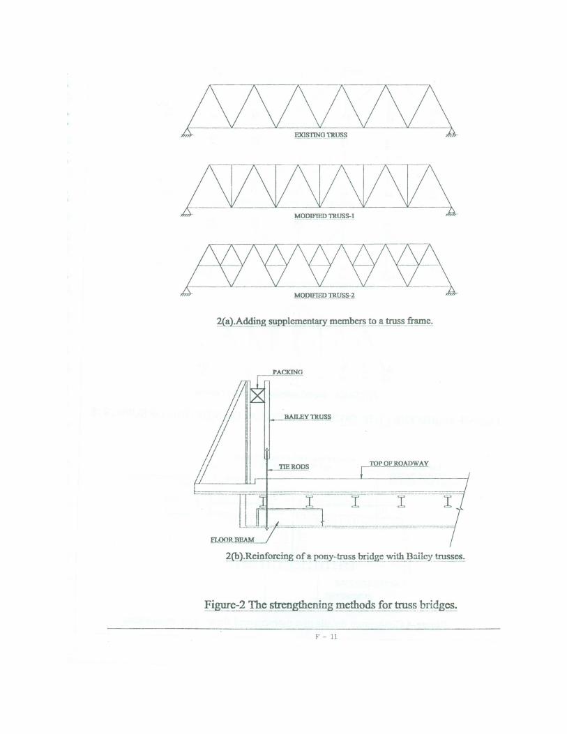
In truss bridges, additional members could be in the form of diagonals to
create double diagonal panels or reduce the effective length of compression
members (Figure 2a). The addition of an entire truss in deck tmsses or using
bailey bridges to be inside existing through trusses connected to existing floor
system through hangers (Figure 2b) could be another form of the same
method. Generally, an addition of a member or a strengthening of a member
cross section will only provide relief against the loads added afterwards.
However, if dead loads too should be distributed to the new a<lde<l members,
the dead load needs to be relieved of the member initially before the
strengthening (Pritchard, 1992). This could be a method that can he adapted to
many truss bridges in Sri Lanka.
Adding supports or moving supports
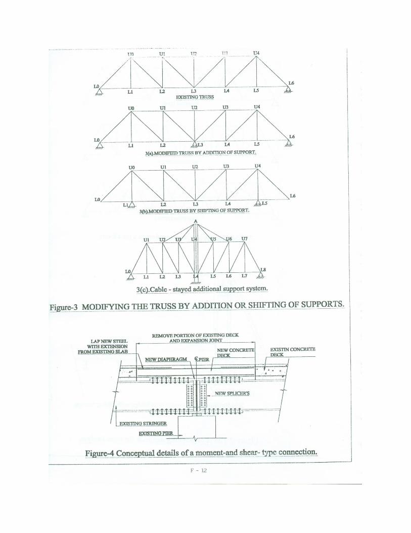
In certain instances, it may become possible to provide an additional support
system to enhance the carrying capacity of a bridge. For example, a single span truss bridge could be changed to a 2 span continuous bri<lg.:- hy providing
a single pier at the ccntcr of the span (Figure 3a). Sometimes, instead of
providing an additional support, it may be possible to shift or change the
support of a length of a panel in tmss bridges (Figure 3b) or it could be
converted to a cable stayed bridge by providing a cable system from an
additionally constructed ccnter pier (Figure 3c). However, the slrncturc should
be fully analyzcd for the new stnictural behavior and strengthened at required
locations. This method is only suitable if the addition of support i~ physically,
structurally and economically feasible.
F - 3
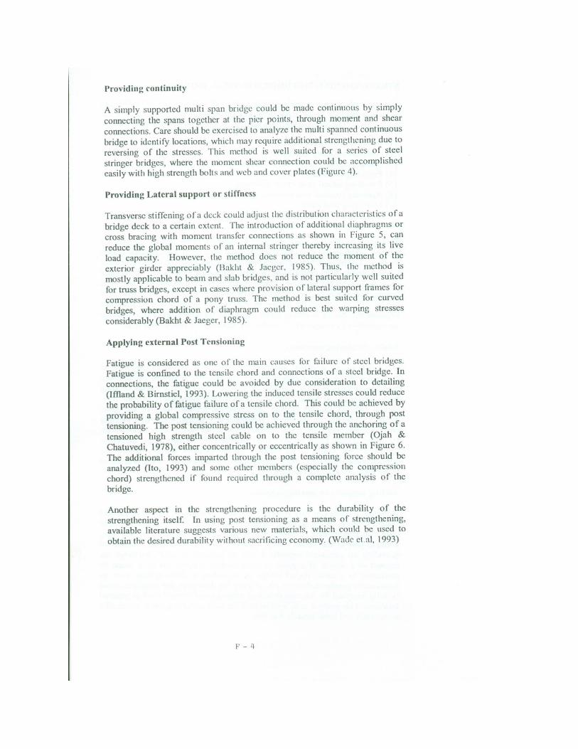
Providing continuity
A simply supported multi span bridge could be made continuous by simply connecting the spans together at the pier points, through moment and shear connections. Care should be exercised to analyze the multi spanned continuous bridge to identify locations, which may require additional strengthening due to reversing of the stresses. This method is well suited for a series of steel stringer bridges, where the moment shear connection could be accomplished easily with high strength bolts and web and cover plates (Figure 4).
Providing Lateral support or stiffness
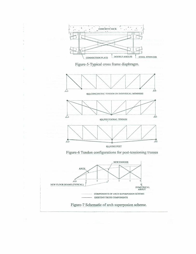
Transverse stiffening of a deck could adjust the distribution characteristics of a bridge deck to a certain extent. The introduction of additional diaphragms or cross bracing with moment transfer connections as shown in Figure 5, can reduce the global moments of an internal stringer thereby increasing its live load capacity. However, the method docs not reduce the moment of the exterior girder appreciably (Bakht & Jaeger, 1985). Thus. the method is mostly applicable to beam and slab bridges, and is not particularly well suited for truss bridges, except in cases where provision of lateral support frames for compression chord of a pony trnss. The method is best suited for curved bridges, where addition of diaphragm could reduce the warping stresses considerably (Bakht & Jaeger, 1985).
Applying external Post Tensioning
Fatigue is considered as one of the main causes for failure of steel bridges. Fatigue is confined to the tensile chord and connections of a steel bridge. In connections, the fatigue could be avoided by due consideration to detailing (Iffland & Birnsticl, 1993). Lowering the induced tensile stresses could reduce the probability of fatigue failure of a tensile chord. This could be achieved by providing a global compressive stress on to the tensile chord, through post tensioning. The post tensioning could be achieved through the anchoring of a tensioned high strength steel cable on to the tensile member (Ojah & Chatuvedi, 1978), either concentrically or eccentrically as shown in Figure 6. The additional forces imparted through the post tensioning force should be analyzcd (Ito, 1993) and some other members (especially the compression chord) strengthened if found required through a complete an:ilysis of the bridge.
Another aspect in the strengthening procedure is the durability of the strengthening itself. In using post tensioning as a means of strengthening, available literature suggests various new materials, which could be used to obtain the desired durability without sacrificing economy. (Wade et.al, 1993)
F - 4
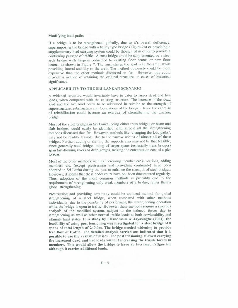
Modifying load paths
If a bridge is to be strengthened globally, due to it's overall deficiency,
superimposing the bridge with a bailey type bridge (Figure 2b) or providing a supplementary load carrying system could be thought of in order to provide a
continuing passage of traffic. A truss bridge could be supplemented by a steel arch bridge with hangers connected to existing floor beams or new floor beams, as shown in Figure 7. The truss shares the load with the arch, while providing lateral stability lo the arch. The method obviously could be more expensive than the other methods discussed so far. I lowcvcr, this could provide a method of retaining the original structure, 111 cases of historical
signi ficancc.
APPLICABILITY TO THE SRI LANKAN SCENARIO
A widened structure would invariably have to cater to larger dead and live loads, when compared with the existing structure. The increase in the dead load and the live load needs to be addressed in relation to the strength of
superstructure, substructure and foundations of the bridge. 1 lcmx the exercise of rehabilitation could become an exercise of strengthening the existing bridge.
Most of the steel bridges in Sri Lanka, being either truss bridges or beam and slab bridges, could easily be identified with almost all the strengthening methods discussed thus far. However, methods like 'changing the load paths', may not be readily feasible, due to the narrow widths of almost all of these
bridges. Further, adding or shilling the supports also may not be that feasible, s ince generally steel bridges being of larger spans (especially tmss bridges) span fast-flowing rivers or deep gorges, making the construction cost of a pier to soar.
Most of the other methods such as increasing member cross sections, adding members etc. (except prestressing and providing continuity) have been adopted in Sri Lanka during the past to enhance the strength o f steel bridges. However, it seems that these endeavours have not been documented regularly. Thus, adoption of the most common methods is probably due to the requirement of strengthening only weak members of a bridge, rather than a global strengthening.
Prcstrcssing and providing continuity could be an ideal 1m:thod for global strengthening of a steel bridge, when compared with other methods individually, due to the possibility of performing the strengthening operation while the bridge is open to traffic. However, these methods require a rigorous analysis of the modified system, subject to the induced forces due to strengthening as well as other normal traffic loads at both serviceability and ultimate limit states. In a study by Chandrasiri & Jayasin~he (2001), the feasibility of using post tensioning was investigated for a steel hridge of 8 spans of total length of 240.0m. The bridge needed widening to provide free flow of traffic. The detailed analysis carried out indicated that it is possible to use the available trusses. The post tensioning allowed carrying the increased dead and live loads without increasing the tensile forces in members. This would allow the bridge to have an increased fatigue life although it carries additional loads.
F' - 5
Irrespective of the applicability of various methods, for strengthening a particular bridge, the cost aspects ofthc chosen method with the improvement of the level of service provided should be the deciding criteria, in selecting a strengthening procedure. This could be achieved through estimating various costs involved in each method and by introducing what is known as an 'improvement factor' to the cost analysis (NCHRP, 293).
Improvement factor could be defined as the enhanced load effect (e.g. increase in flexural capacity of a beam at mid span) divided by the cost of the strengthening method. Hence higher the improvement factor, better the chosen strengthening method would be, thus giving us a decision making device to compare between the strengthening methods available.
DETERMINATION OF ECONOMIC FEASIBILITY
Out of the total of 3700 steel bridges in Sri Lanka 2372 bridges arc with a width below 8.0 m as indicated in Figure I . Of the 854 steel bridges 782 bridges fall on to the same category. Assuming that these stcrl bridges would have to be replaced or widened within the next twenty-five years, the budget requirement for superstructure replacement alone is about Rs. l.9 billion with the prices prevailing in 2001. To arrive at this cost, the data given in Table I was used. Based on this data, it is reasonable to consider a cost of Rs. 20000/= per m2
. The completed bridge was considered to have a width of JO.Orn. The average length of these bridges is estimated as 12.0m on the basis of the data available on lengths.
In analyzing a bridge having deficiencies, the Engineer is faced with making a decision as to either replace or strengthen/rehabilitate. This decision should be based not only on the initial expenditure but also on the life cycle cost of the structure. The main problem faced in doing so is the estimation of the life of a structure, either new or strengthened. In a new structure, if designed in accordance with BS 5400, a life span of 120 years could be assumed. However, in an existing bridge, the estimation of remaining life basically depends on engineering judgement. Primarily, in steel bridges the remaining life is dictated by fatigue limits. Though there have been attempts at estimating fatigue life through field data (Mohammadi, Guralnick, et.al., 1998), these methods arc based on extensive collection of data on traffic volumes, structural condition and growth rates, axle loads, etc .. making them subjective too.
Hence experience in dealing with bridges is of paramount importance when estimating the remaining life of an existing or strengthened bridge. With the decision being based on economical analysis, various types of economic feasibility techniques could be utilized in arriving at a decision.
F - 6
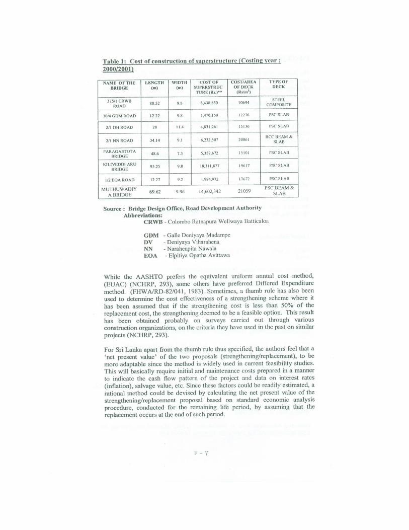
Table 1: Cost of construction of superstructure (Costing y<'ar:
2000/2001)
NAMF. OFTIIE U:NGTII WIDTII COST Of COSf/AREA
BRIDGE (m) (m) SUPERSTRUC OFDF.CK TURE(Rs.)•• (Rs/m1
)
375/1 CRWl3 80.52 9 .8 8.43~.850 10694
ROAD
J 0/4 GDM ROAD 12.22 98 1.470.150 12276
2/1 OH ROAD 28 11.4 4.811,2<>1 15136
2/ 1 NN ROAD 34 14 9 .1 6,212,507 20061
PARAGASTOTA 48.6 7.3 5,357,672 15101 BRIDGE
KILIVEDOI ARU 95.25 9.8 18,311,877 1%17 BRIDGE
1/2 EOA ROAD 12 27 9.2 1,994,972 17672
MUTHUWADIY 69.62 9.96 14,602,342 21059
ABRIDGE
Source: Dridge Design Office, Road Development Authorily Abbreviations:
TYPE Of DECK
sn,EL COMPOSITE
rsc SLAB
r sc SLAB
RCCllEAM & SLAB
PSCSLAll
r sc SLAll
PSC SLAB
l'SC' UEAM & SLAB
CRWB - Colombo Ratnapura Wcllwaya Batticaloa
GDM DV NN EOA
- Ga11c Dcniyaya Madampc - Dcniyaya Viharahcna - Narahenpita Nawala - Elpitiya Opatha Avittawa
While the AASHTO prefers the equivalent uniform annual cost method,
(EUAC) (NCHRP, 293), some others have preferred DifTcred Expenditure
method. (FHWNRD-82/041, 1983). Sometimes, a thumb rule has also been
used to determine the cost effectiveness of a strengthening scheme where it
has been assumed that if the strengthening cost is less than 50% of the replacement cost, the strengthening deemed to be a feasible option. This result
has been obtained probably on surveys carried out through various construction organizations, on the criteria they have used in the past on similar
projects (NCHRP, 293).
For Sri Lanka apart from the thumb rule thus specified, the authors feel that a
'net present value' of the two proposals (strcngthening/rcplaccment), to be
more adaptable since the method is widely used in current feasibility studies.
This will basically require initial and maintenance costs prepared in a manner
to indicate the cash flow pattern of the project and data on interest rates
(inflation), salvage value, etc. Since these factors could be readily estimated, a
rational method could be devised by calculating the net present value of the
strengthening/replacement proposal based on standard economic analysis procedure, conducted for the remaining life period, by assuming that the
replacement occurs at the end of such period.
r - 7
CONCLUSION
The decision whether lo replace or rehabilitate an existing bridge is :1 question faced by engineers when dealing with bridge construction. There are number of bridge strengthening methods that can be used for rehabilitation of bridges. Out of these providing continuity and addition of external prestressing are identified as the most suitable methods for Sri Lanka.
Since the replacement of the superstructure of the 689 bridges of width less than 8.0m alone would cost about Rs. 1.9 billion, it can be suggested !ha! rehabilitation of steel bridges should be seriously pursued in future. It is suggested that the economic feasibility of replacement and rehabilitation could be based on net present value of two alternatives. The rehabilitation would be attractive if it costs less than 50% of replacement. T:.;s indicates that there could be considerable cost savings if rehabilitation is adopted for a considerable number of steel bridges.
ACKNOWLEDGEMENT
The Authors wish to thank the entire management of the Road Development Authority and the Civil Engineering Department of the University of Moratuwa, for allowing the publishing of this paper and the support rendered.
List of References
Bakht, B., Jaeger L.G. ( 1985), Bridge Analysis simplified, McGraw hill Inc., USA, 294 p.
British Standards Institution, BS5400 Parts I and2 ( 1978).
British Standards· Institution, BS5400 Parts 3, 4and 5 (I~ .
Chandrasiri B.V.D.N., Jayasinghe M.T.R. (2001), "Rehabilitation of steel bridges using prestressing", Engineer, journal of Institution of Engineers, Sri Lanka, Vol. 35 No. 2 .
Dawe, P.H., (1993), "The Assessment of Bridges-- DOT rcquiremen!s", Bridge Management 2, edited by I larding et.al. , Thomas Telford, London, pp l -7
lfiLand, J.S.B., Birnstiel, C ., (1993), "Causes of Bridge Deterioration", Bridge Management 2, edited by Harding et.al., Thomas Telford, London , pp 8-18.
Ito, N. (1993), "Research of the External Prcstressing Method for the Three Span Continuous Road Bridge", FIP Symposium, Japan, Vol. 2 pp 967-974
Johnson,R.P.,Buckby,R.J.( 1986). Compos ite Structures of st.££1_and concrete Volume 2 : Bridges, William Collins & co. Ltd., London, 420p
Lin,T.Y., Bums,NJI., Design of prcstrcsscd Concrete Structures. Third Edition, John Wiley & Sons Inc., USA, 646p
Federation Intemationale de la precontraintc, (1996), Materials and Systems for External Prestressing, FIP State of the art report, London, 15p
[,' - 8
Mohamadi, J., Guralnick, S.A., Polcpeddi, R.(1998) "Bridge Fatif,'l!C life estimation from Field Data", Practice Periodical on Structural Design & Construction. Vol.3, pp 128-133
NCHRP report 293, (1987), Methods of Strengthening Existing Highway Bridges, Transportation Research Board, Washington, l 14p
Ojha, S.K., Johorcy, M.C., Chatuvedi, D.C., (1978) "Prestressing of the steel truss bridge at Dharasu for increasing its Load carrying Capacity"- Institution of Engineers (India) Journal - Cl Vol.58, pp303-308
Pritchard I3. (1992), Bridge Design for Economy & Durability • Thomas Telford. London, 172p U.S. Dept. of Transportation -Federal Highway Administration, Washington (1983), Upgrading deficient through truss Bridges - Report No. FHW A/RD-82/041, l 22p
Virlogeux, M., (1993)" External Prestressing in I3ridges"-FIP Symposium • Kyoto. Japan. Vol. 2, pp843-852
Wade, C.J., Abdelrahman, A.A., Rizkalla, S.IL, Tadros, G., ( 1993), "First Concrete Highway Bridge in Canada - Prestressed by Carbon Fiber Cables", FIP Symposium Kyoto, Japan, Vol. 2, pp 775-782
p - 9

JOOO
2500
2000
No. 1500
1000
500
0
NO
1400
1200
1000
IIOO
600
400
200
0
KSJ
W<4.0m 4<w<S 8<w
RSI
Abbreviation RSJ ST.TRU CONC
TYPES OF BRIDGF.S Local Scenario
RSJ
756
RSJ
159 530 67
ST.THU ('ONC
TYPE
ST.TRU
98
OTIIEK
CONC
2647
O'fl!ER
243
WIDTH OF BRIOGES (Local Srennrio)
ST.TRU CONC OTIIF.R
l!l\\<4.0M
C4<w<ll
1!18<w
ST.TRU CONC OTIIER
6 89 7 87 1315 179 5 1243 57
Rollcxl Steel Joist System Steel through/deck truss Concrete Bridge
Figure t : ·n,e Details of the Bridgrs Based on Type a11d Width
~- - 10
/\J\/\i\1\1\ A EXISTING TRUSS A-
~ A MODIFIED~A-
2(a).Adding 5-!!Pplementary members to a truss frame.
PACKING
2(b ).Rei.Qfo~ing of a pony-truss btjdge with_ l;l~lcy trus~es.
F' - 11
HO Ul l T.' IP U4 ,. ~v· ~l~~ U--~LS
.IDCJSTlNO TRUSS
3(a).MODIFIED TRUSS BY ADDmON OF SUPPORT.
UO UI U2 U3 U4
"' L6
3(b}.MODIFIBD TRUSS BY SHIFI'ING OF SUPP<!~T.
A
3{c1Cable - stayed additional supp2rt system.
FJEUrf?-3 ~DIFYING THE TRUSS BY ADDIDON OR SIITFTING Of SUPPORTS.
LAP NEW STl!BL wrm EX'raNSION M
RBMOVB PORTION OF EXJSTING DECK
,__ ___ AND~~HXP= ANSl=ON~ JO=INT~----
NEW CONCRETE
~NEW!U!.J,!!!!,!~~O~M~ iPIER. ,-=Dl!ClC.===----1
j ltl~---·-· ·'"--=-.. .. : ~ _ N~_t,PLTCER'S
F' - 12
Hgurc-5-Typical cross frame diaphragm.
6(a).CONCI!NTRIC TENDON ON JNDTVIDUAL MEMRERS
6(1,}.POLYGONAL TENDON
' 6{c).KINO POST
Figure-6 Tendon configurations for post-tensioning trusses
I __J
I I I
~~ f!,OORBP.AMS ffYPICALLL------- 'f. SYMETRICAL
ABOUf
----- COMPONENTS OF ARCH SUPERPOSION SCHEME
EXISTING TRUSS COMPONENTS
fi~c-'[_Schematic of_arch sup~_Qsion scheme.