region regional university transportation center final report
TRANSCRIPT
USDOT Region V Regional University Transportation Center Final Report
IL IN
WI
MN
MI
OH
NEXTRANS Project No. 139TUY2.1
Develop Preliminary Engineering Design and Study the Benefits of Providing an
Access to the Indiana Toll Road at State Road 327 near Orland, IN
By
Dr. Ryan Overton, P.E. Associate Professor Trine University
DISCLAIMER
Funding for this research was provided by the NEXTRANS Center, Purdue University under
Grant No. DTRT12‐G‐UTC05 of the U.S. Department of Transportation, Office of the Assistant
Secretary for Research and Technology (OST‐R), University Transportation Centers Program.
The contents of this report reflect the views of the authors, who are responsible for the facts
and the accuracy of the information presented herein. This document is disseminated under
the sponsorship of the Department of Transportation, University Transportation Centers
Program, in the interest of information exchange. The U.S. Government assumes no liability for
the contents or use thereof.

USDOT Region V Regional University Transportation Center Final Report
TECHNICAL SUMMARY
NEXTRANS Project No 019PY01Technical Summary - Page 1
IL IN
WI
MN
MI
OH
NEXTRANS Project No. 139TUY2.1 Final Report, 10/05/2016
Develop Preliminary Engineering Design and Study the Benefits of Providing an
Access to the Indiana Toll Road at State Road 327 near Orland
IntroductionThis report includes the preliminary design aspects for the proposed new toll exit at the
intersection of I-80/90 and State Road 327 in Orland, Indiana as seen in Figure 1. This report
also gives our understanding of the project, what services were provided, and an estimated
construction cost for the project.
Figure 1: Aerial Photograph of Site
Proposed 500‐Acre
Manufacturing Site

NEXTRANS Project No 019PY01Technical Summary - Page 2
FindingsA new toll road exit is proposed at the intersection of I-80/90 and SR 327 in Orland,
Indiana. The new exit is needed to facilitate travel for a proposed manufacturing plant to be
established on a 500-acre site east of SR 327 and south of I-80/90 (see Figure 1).
The construction will consist of on and off ramps that connect to both the east and
westbound lanes of the toll road and a single toll plaza. There will be a small parking lot and a
utility building next to the toll plaza. A bridge will be needed over the toll road so vehicles can
access the toll road from the east and west. Finally, the new access road will connect to SR 327
that is already in place.
Existing Conditions
The site was visited to evaluate the existing conditions. The area south of the toll road is
mainly a crop field. There is a deep valley on this side of the toll road. On the north side of the
toll road the land is a grassy field with several rolling hills. These hills cause the elevation to
vary by about 30 feet across the entire site. In addition, there is a drainage ditch constructed
parallel to both sides of the toll road. City utilities are not present at the site, and the nearby
residence on the south side of the toll road appears to be on a well and septic system.
RecommendationsI. Roadway Alignment
Horizontal Alignment
The horizontal alignment was designed according to the Indiana Design Manual (IDM)
requirements. The design was restricted by an existing overpass on the east and existing
wetlands on the west. All driving lanes were designed as 16-ft lanes to accommodate the
anticipated truck traffic. The horizontal curve radii were determined assuming an 8% maximum

NEXTRANS Project No 019PY01Technical Summary - Page 3
superelevation per IDM 43-3.01. The design consists of a 444-ft, a 314-ft and three 214-ft radius
curves for 40, 35 and 30 mph design speeds, respectively. These radii are the minimum radii as
stated in Fig 43-3A(3) of the IDM for an 8% superelevation. The design meets the minimum
deceleration lengths of 500 ft for a 30 mph curve and 460 ft for a 40 mph curve according to Fig
54-3A of the IDM. The alignment also meets the minimum acceleration length of 1,200 feet
stated in IDM chapter 48-4.02(3).
Vertical Alignment
The vertical alignment was designed within the specifications of Figure 54-2A of the
IDM. The maximum upgrade allowed for a rural interchange is five (5) percent. The maximum
allowable downgrade is five (5) percent. The acceleration and deceleration lanes running
parallel to the existing toll road were designed at the same grade and elevation of the existing toll
road. The overpass elevation was designed to provide a minimum clearance of 16 feet as stated
in 54-3.02(3) of the IDM. An additional seven (7) feet was added to the elevation of the
overpass abutments in order to compensate for the anticipated depth of the bridge deck structure.
The seven (7) feet was determined from previous INDOT overpass designs from previous
projects.
Intersection at SR 327
The preliminary design also included intersection improvements at SR 327 and the toll
plaza on/off ramp. The toll plaza ramp is designed to have a left turn lane onto SR 327 and a
second lane for the combination of through traffic and right turn traffic onto SR 327. A right
turn lane will be needed on the southbound lane of SR 327. An additional lane is also needed for
the northbound lane of SR 327 in order to convert the existing lane into a left turn lane. The
added lane on SR 327 is designed to be a combination lane for through traffic and right turn
NEXTRANS Project No 019PY01Technical Summary - Page 4
traffic. A corner radius of 20 feet was used in the design located on SR 327. This is the
minimum corner radius allowed according to Figure 46-2D of the IDM for a 90 degree angle
with passenger cars. This minimum radius was used to limit the truck traffic traveling on SR
327. This also assumes that the entrance to the 500-acre site will be directly across SR 327 from
the toll plaza ramp. A traffic signal will be needed for this intersection, but is beyond the scope
of our services.
II. Earthwork
Borrow Pits
From the AutoCAD renderings and calculations, it has been projected that there is a need
for 152,036 cubic yards of fill. To minimize costs, the fill will be gathered from onsite borrow
pits. Because most of the fill for the roadway will be needed on the north end of the project, there
will be two borrow pits on the north side of the toll road. These two pits are depicted as the red
boxes on Figure 2. The larger onsite pit will be to the northeast of the entrance/exit ramp loop.
The dimensions of the borrow pit will be approximately 600 feet long 600 feet wide and 10 feet
deep. The second pit will be located to the northwest of the entrance/exit ramp loop. This pit will
be approximately 200 long 200 wide and 10 deep. On the south side of the toll road there will be
a natural retention pond between the toll road and the SR 327 access route. The pond is
represented by the blue box in Figure 2. Minimal fill needs on the south end of the project can be
extracted from this area.

NEXTRANS Project No 019PY01Technical Summary - Page 5
Figure 2: Proposed Borrow Pits and Retention Pond
III. Geotechnical Considerations
Subsurface Conditions
Soil borings could not be performed for this project due to the limited time and no
funding. In order to have some understanding of the subsurface conditions the United States
Department of Agriculture (USDA) web soil survey was used. Figure 3 shows an aerial
photograph of the site with the soil classifications indicated for the top six (6) feet of soil present
at the project site. Directly to the north of the project the soil is Udorthent loamy sand (Ud) that
is adjacent to the wetland further north. Just south of that is where the loop will be located for the
exit and entrance ramps of the westbound lanes. This area is predominantly Casco gravelly sandy
loam (CaC). South of the toll road at the west end of the area is Boyer-Ormas loamy sand (BoD).
This is where the bridge will be located over the toll road, also the exit ramp of the east bound
lanes. East of that is Chelsea fine sand (ChB), here is where the entrance ramp to the east bound

NEXTRANS Project No 019PY01Technical Summary - Page 6
lanes will be. The soil south of the toll road at the east is Casco gravelly sandy loam (CaD2).
There is a deep valley here that will be used as a retention pond. The last soil that is within the
project area is Kosciusko sandy loam (KoB). The land in the project area is good subsurface
grade soil that is generally class A-2. The groundwater table was not found within the top six feet
of soil.
Figure 3: Subsurface Soil Types at the Site
Recommended Future Investigation
Site soil borings should be drilled to know the exact soil type that is deeper than the
topsoil. The soil borings can also provide information on the quality of the soil. The projected
soil borings are as follows. Roadway borings should be 10 feet deep and located every 200 feet
staggering side to side of the purposed roadway. There will need to be 39 roadway borings for
our roadway. The utility building will need two borings, each at diagonal corners drilling to 15
NEXTRANS Project No 019PY01Technical Summary - Page 7
feet. Finally the bridge will need three borings, one at the center support between the east and
west bound toll road lanes, one to the south of the toll road where the bridge will start, and
finally one at the north of the toll road where the bridge will end.
IV. Toll Plaza Design
Site Layout
We developed a preliminary site layout for the toll plaza using the Toll Plaza Design. We
referenced lane widths, awning height, and booth widths for the toll booths and lanes to
determine accurate distances so cars and semis have safe access to the toll booths. The height of
the awning (16-ft 4-in) was determined by using the Toll Plaza Design book and the height
requirement for bridge overpasses. We used the Trip Generation Manual to determine that the
number of toll booths needed was three (3). Also, referencing similar toll plazas on Google
Maps we developed the size of the building and parking lot.
Utilities
The Administration building requires electric, water, and sewer services. The proposed
city utilities provided for the manufacturing plant on the 500-acre site will also service the
Administration building. There is already an overhead power line, which we will connect to for
the electrical supply.
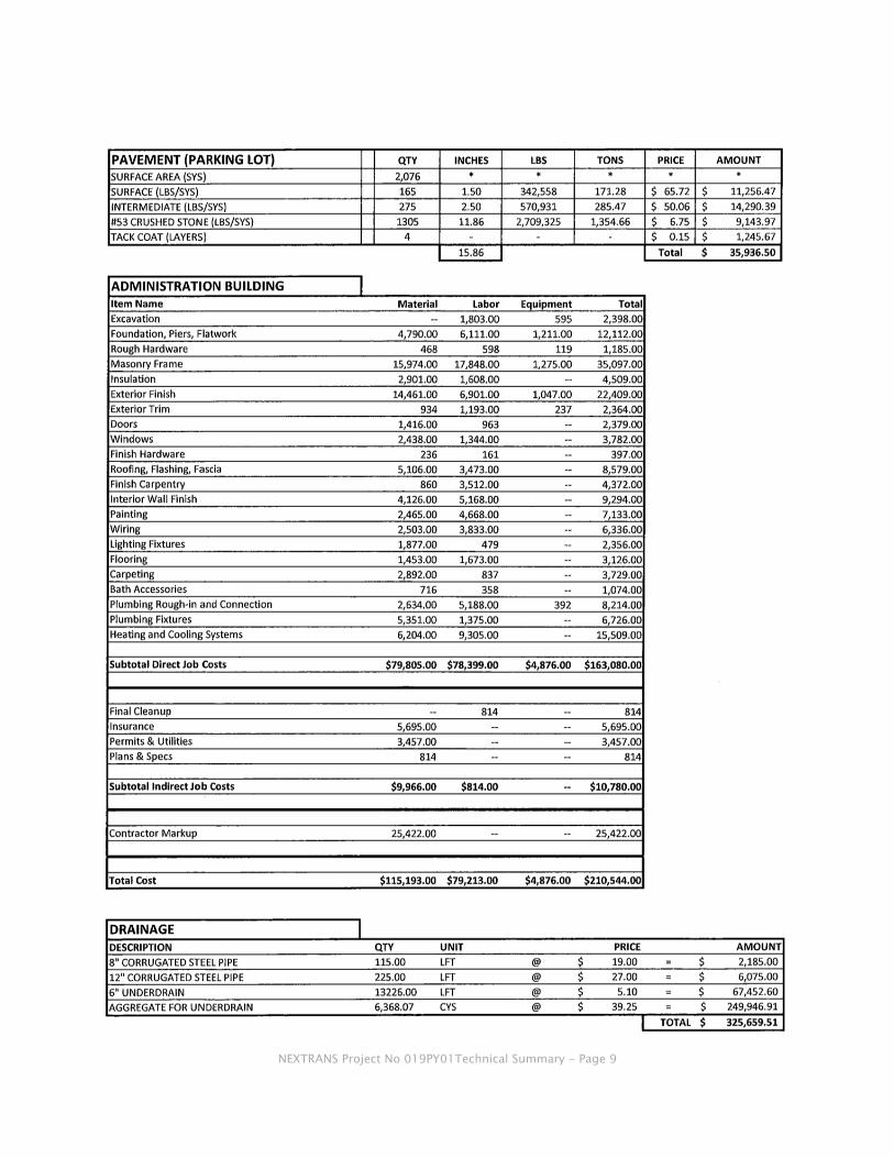
V. Construction Cost Estimate
The estimated construction cost of the project is $6,782,945. This cost includes the
estimated construction cost of the bridge, soil borings, toll booths and awning,
administration building, pavement, drainage and excavation costs and the cost of the land. A
summary of these costs is as follows:

NEXTRANS Project No 019PY01Technical Summary - Page 8
NEXTRANS Project No 019PY01Technical Summary - Page 9

NEXTRANS Project No 019PY01Technical Summary - Page 10

NEXTRANS Project No 019PY01Technical Summary - Page 11
ContactsFormoreinformation:
Dr. Ryan Overton, P.E. Trine University One University Avenue 260.665.4892 260.665.4814 [email protected] www.trine.edu
NEXTRANS Center Purdue University ‐ Discovery Park 3000 Kent Ave. West Lafayette, IN 47906 [email protected] (765) 496‐9724 www.purdue.edu/dp/nextrans