refrigeration plans for dry-cleaning … · refrigeration plants for dry-cleaning — key 2 artic...
TRANSCRIPT

1
REFRIGERATION PLANS FOR
DRY-CLEANING MACHINES

Refrigeration plants for dry-cleaning — key
2
Artic Line coil
1) Maneurop compressor 2) Rotalock compression cock 3) Cooling solenoid valve 4) Drying solenoid valve 5) Check valve 6) Heat regeneration battery 7) Check valve 8) Rotalock corner 9) Condenser tank 10) Liquid Rotalock cock 11) Dehydration unit filter 12) Liquid indicator 13) Liquid solenoid valve 14) "batt. EV" expansion valve 15) Evaporator battery 16) Rotalock intake cock 17) "artic line" expansion valve 18) artic line" solenoid valve 19) water pressure switch valve 20) 1/4 cock for pressure switch valve 21) Low pressure switch 22) High pressure switch 23) Low pressure gauge 24V ) 24V 50Hz coils
( 1 ) The Compressor
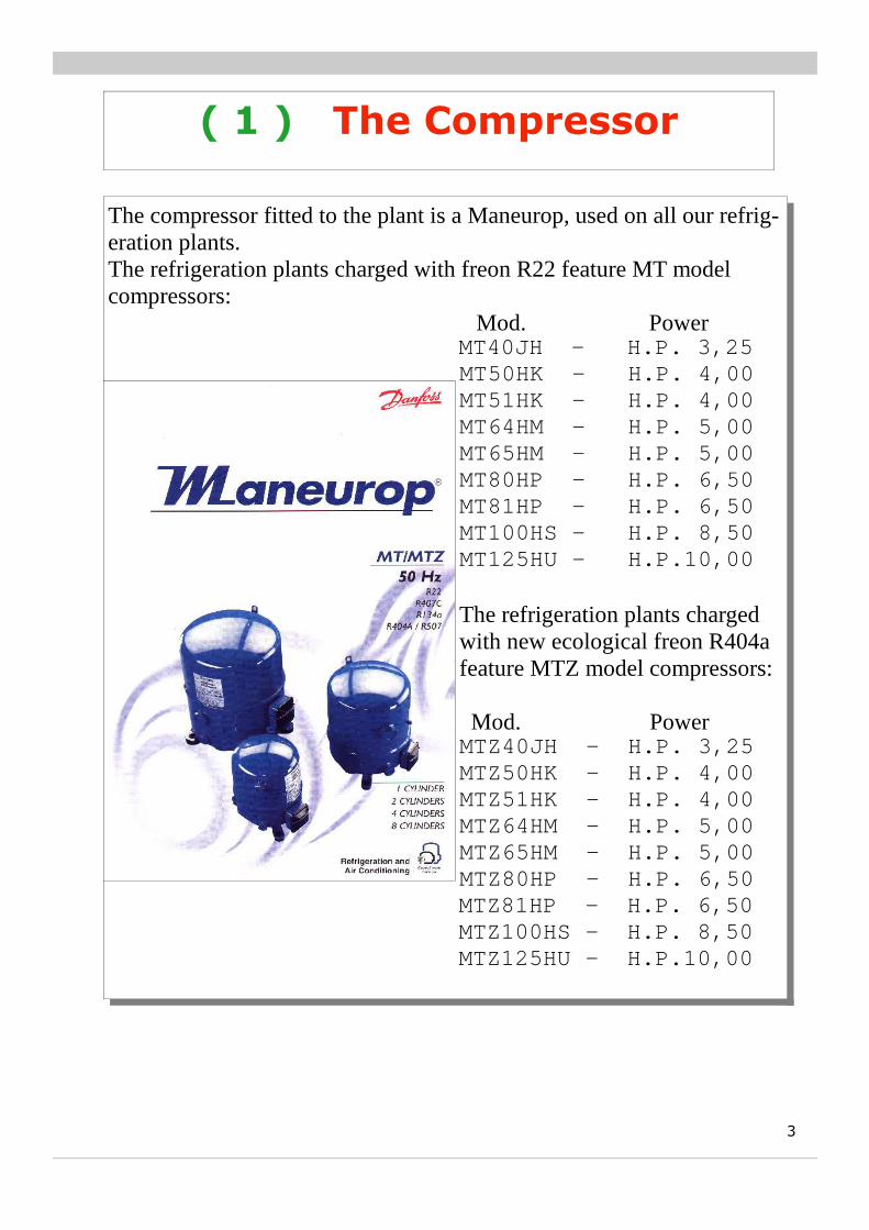
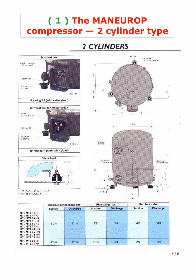
The compressor fitted to the plant is a Maneurop, used on all our refrig-eration plants. The refrigeration plants charged with freon R22 feature MT model compressors: Mod. Power MT40JH - H.P. 3,25
MT50HK - H.P. 4,00 MT51HK - H.P. 4,00 MT64HM - H.P. 5,00 MT65HM - H.P. 5,00 MT80HP - H.P. 6,50 MT81HP - H.P. 6,50 MT100HS - H.P. 8,50 MT125HU - H.P.10,00 The refrigeration plants charged with new ecological freon R404a feature MTZ model compressors: Mod. Power MTZ40JH - H.P. 3,25 MTZ50HK - H.P. 4,00 MTZ51HK - H.P. 4,00 MTZ64HM - H.P. 5,00 MTZ65HM - H.P. 5,00 MTZ80HP - H.P. 6,50
MTZ81HP - H.P. 6,50 MTZ100HS - H.P. 8,50 MTZ125HU - H.P.10,00
3

4
( 1.b ) The Compressor troubleshooting
Problem Possible cause Check
Pos. 1) The compressor fails to start
• Power break. • Thermal cutout has
tripped (see pos. 3)
1. Check fuses. 2. Check pressure switch contacts
(21 - 22)
Pos. 2) The compressor works intermittently
• Low pressure switch trips (21)
• Intake pressure too low
1. Check the freon charge. There could be a leak.
2. Check the expansion valve (14). The filter could be blocked.
3. Check the evaporator battery (15). It could be dirty.
Pos. 3 The compressor is too hot
• The compressor is only cooled by intake (green circuit)
• Insufficient freon, prob-able leak
• Expansion valve (14) • Pressure switch valve (19) • Thermal switch tripped
(located inside compres-sor)
1. If the compressor has stopped due to overheating, wait at least three hours before starting again.
2. Check the freon charge in the refrigeration plant. There could be a leak.
3. Check the expansion valve (14). The filter could be blocked.
4. Check the dehydration unit filter (11): This could be blocked.
5. Check the pressure switch valve (19). Not enough water may be circulating.

5
( 2 ) The Compression Cock
Pos. 4) The purpose of the compression cock (2) or rotalock valve is mainly to interrupt the compression circuit (RED circuit) in case of servicing. Example: if the compressor has to be changed, the pin on the rear of the cock, see figure*, must be turned clockwise.
INSIDE THE
BLACK CAP IS
THE PIN
( 16 ) The Intake Cock
Pos.5) The purpose of the intake cock (16) or rotalock valve is to interrupt the intake circuit (GREEN circuit) in case of servicing.
( 10 ) The Liquid Cock
Pos.5b) The purpose of the liquid cock (10) or rotalock valve is to interrupt the liquid circuit (YELLOW circuit) in case of servicing
( 20 ) The 1/4 Cock for Pressure Switch Valve
Pos.5c) The purpose of the 1/4 cock (20) is to supply, through a capillary pipe, the water pressure switch valve (19), the pressure switch KP5 (25) and the high pressure gauge (25). It is mainly used when jobs are carried out on the component parts: pressure switch valve (19), high pressure switch (22), high pressure gauge (25), see page 21.
6
( 4 ) EVR10 Solenoid valve drying stage
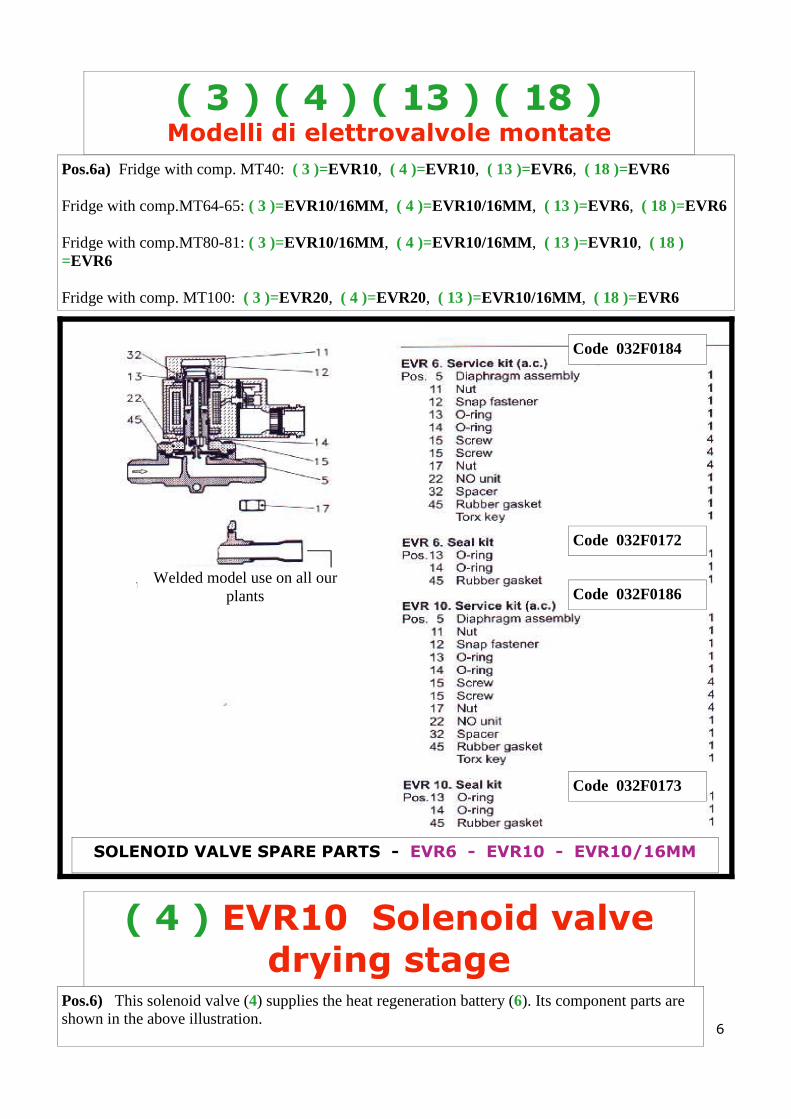
Pos.6) This solenoid valve (4) supplies the heat regeneration battery (6). Its component parts are shown in the above illustration.
( 3 ) ( 4 ) ( 13 ) ( 18 ) Modelli di elettrovalvole montate
Code 032F0184
Code 032F0172
Code 032F0186
Code 032F0173
Pos.6a) Fridge with comp. MT40: ( 3 )=EVR10, ( 4 )=EVR10, ( 13 )=EVR6, ( 18 )=EVR6 Fridge with comp.MT64-65: ( 3 )=EVR10/16MM, ( 4 )=EVR10/16MM, ( 13 )=EVR6, ( 18 )=EVR6 Fridge with comp.MT80-81: ( 3 )=EVR10/16MM, ( 4 )=EVR10/16MM, ( 13 )=EVR10, ( 18 )=EVR6 Fridge with comp. MT100: ( 3 )=EVR20, ( 4 )=EVR20, ( 13 )=EVR10/16MM, ( 18 )=EVR6
SOLENOID VALVE SPARE PARTS - EVR6 - EVR10 - EVR10/16MM
Welded model use on all our plants
7
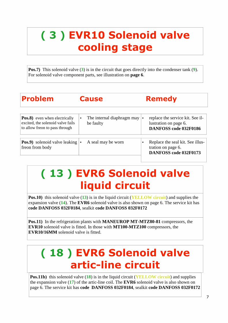
Pos.7) This solenoid valve (3) is in the circuit that goes directly into the condenser tank (9). For solenoid valve component parts, see illustration on page 6.
Problem Cause Remedy
Pos.8) even when electrically excited, the solenoid valve fails to allow freon to pass through
• The internal diaphragm may be faulty
• replace the service kit. See il-lustration on page 6.
DANFOSS code 032F0186
Pos.9) solenoid valve leaking freon from body
• A seal may be worn • Replace the seal kit. See illus-tration on page 6.
DANFOSS code 032F0173
( 13 ) EVR6 Solenoid valve liquid circuit
Pos.10) this solenoid valve (13) is in the liquid circuit (YELLOW circuit) and supplies the expansion valve (14). The EVR6 solenoid valve is also shown on page 6. The service kit has code DANFOSS 032F0184, sealkit code DANFOSS 032F0172
Pos.11) In the refrigeration plants with MANEUROP MT-MTZ80-81 compressors, the EVR10 solenoid valve is fitted. In those with MT100-MTZ100 compressors, the EVR10/16MM solenoid valve is fitted.
( 18 ) EVR6 Solenoid valve artic-line circuit
Pos.11b) this solenoid valve (18) is in the liquid circuit (YELLOW circuit) and supplies the expansion valve (17) of the artic-line coil. The EVR6 solenoid valve is also shown on page 6. The service kit has code DANFOSS 032F0184, sealkit code DANFOSS 032F0172
( 3 ) EVR10 Solenoid valve cooling stage

( 24 V ) The coil
Pos.12) the coils are all 24 V. For installations and after-sales service, see the illustrations be-low
8
The coil Check the voltage indicated on the coil. The O-rings must be correctly fitted.
Fitting must be done correctly. First of all tighten with the fingers and then make another half turn using a spanner. Remember that the plastic thread will not withstand over-tightening.
When changing the coil, manual tools may be required, e.g., two screwdrivers.

( 11 ) The dehydration unit filter
Pos.13) The dehydration unit filter ( 11 ) is one of the major component parts requiring inspec-tion: every time the plant is serviced, this should be changed, see pos. 16 (thanks to its molecular sieve, it is able to trap and hold humidity
9
Operation
To operate smoothly, a refrigeration plant must be clean and dry inside. Before switch-ing the plant on, all humidity must be elimi-nated by creating a vacuum at a pressure of 0.05 mbar abs. During operation, impurities and humidity must be constantly trapped and eliminated by means of a dehydration filter containing a solid cartridge consisting of: Molecular sieve (MS), Silica gel (SiO2), active alumina (AL2O3) and a polyester filter fabric (A), fitted at the filter outlet.
The cartridge can be compared to a sponge that absorbs and withholds water. The mo-lecular sieve and the silicagel absorb the water, while the active alumina absorbs acids. Together with the polyester layer A, the solid core B also acts as an impurity filter. The solid core withholds the larger particles of impurities, while the smaller ones are trapped by the polyester. The de-hydration unit filter is therefore able to trap all the particles of impurities larger than 15-20 µm.
In refrigeration plants when expansion oc-curs by means of a capillary pipe, types DN 032s, DN032,5s or DN 033s can be used. These are purposely made for use in plants with capillary pipe.

10
( 11b ) The dehydration unit filter
Pos.13a) The dehydration unit filters (11) used are: Refrigeration plants with MANEUROP ( 1 ) MT40-MT50-MT65 compressor feature the DAN-FOSS DN163 filter. Refrigeration plants with MANEUROP ( 1 ) MT80-MT81 compressor feature the DANFOSS DN164 filter. Refrigeration plants with MANEUROP ( 1 ) MT100-MT125 compressor feature the DANFOSS DN305 filter.
Operation
Humidity penetrates into the refrigeration plant: 1) during plant installation; 2) when the refrigeration plant is opened for
servicing; 3) in case of leaks on the intake side, if this is
subject to high vacuum; 4) when pouring in oil or coolant containing
humidity; 5) in the case of leaks in a water-cooled con-
denser. The presence of humidity in the refrigeration plant can cause: a) blockage of the expansion part due to for-
mation of ice; b) corrosion of metal parts; c) chemical damage to insulation in the case
of sealed or semi-sealed compressors; d) oil decomposition (formation of acids). The dehydration unit filter eliminates the hu-midity remaining after evacuation or which subsequently penetrates into the refrigeration plant. Important! Never use "antifreeze", such as methyl alcohol together with dehydration unit filters. The anti-freeze could damage the filter.
Always change the filter when: - the liquid indicator shows there is too much humidity (yellow colour) - pressure drop through the filter is too high (bubbles in the liquid indicator during normal operation) - every time the refrigeration plant is opened, e.g., in case of changing the compressor or orifice of the expansion valve. Never use the old dehydration unit filter as this could release humidity into the plant.

11
( 11c ) The dehydration unit filter
( 12 ) Liquid indicator
Pos.14) The liquid indicator ( 12 ) is also a very important component part. It indicates whether there is any humidity in the coolant (the indicator must always show green). In the event of its being yellow, this means acidity, which could burn the compressor winding ( 1 ) and stop the expansion valve ( 14-17 )thus strongly jeopardising operation of the refrig-eration plant. Pos.15) If bubbles appear in the liquid indicator. A) This could point to a pressure drop with "filter blocked" (to change the dehydration unit
filter, see pos. 16) B) Insufficient freon in the refrigeration plant, see the illustration below
Position in the refrigeration plant The dehydration unit filter is fitted in front of the refrigeration plant component part to be protected. The dehydration unit filter is normally fitted on the liquid pipe, where above all it protects the expansion valve. The velocity of the coolant in the liquid pipe is low. This permits good contact between the coolant and the dehydration unit filter cartridge and also produces a slight drop in pressure during transit.
Do not pour coolant into the plant only because of bubbles in the liquid indica-tor. First of all ascertain the cause.

12
( 11d – 12c ) Changing the de-hydration unit filter and liquid
indicator
Pos.16) To change the dehydration unit filter ( 11 ) and the liquid indicator ( 12 ) proceed as follows: a Close the liquid cock ( 10 ) rotalock valve, see page 5 b Switch on the refrigeration plant until an intake pressure of 0.2 bar is achieved [seen on
the low pressure gauge ( 23 ) ] c The compressor stops [the low pressure switch trips ( 21 )] d Close the intake cock ( 16 ) rotalock valve, see page 5 e At this point the filter and indicator can be changed. This job should be done as quickly as
possible to prevent penetration of humidity. f Open the liquid cock ( 10 ) and intake cock ( 16 ) again. g After making the replacement, operate the refrigeration plant.
A dehydration unit filter can also be fitted on the intake pipe to protect the compressor against impurities and dehydrate the coolant. The intake filters ("burn out") are used to eliminate the acid after a motor fault. To achieve a small pressure drop, an intake filter must be larger than a liquid pipe filter and should be changed before the pressure drop exceeds the following values: A/C plant 0.5 bar refrigeration plant 0.25 bar freezing plant 0.15 bar
A liquid indicator with humidity indicator is fitted after the dehydration unit filter. When the liquid indicator is fitted after the dehydration unit filter, it indicates: Green: there is no dangerous humidity in the coolant Yellow: the humidity in the coolant is too high upstream of the expansion valve. Bubbles: 1) Pressure drop in dehydration unit filter too
quick 2) There is no sub-cooling 3) Not enough coolant in refrigeration plant
If the liquid indicator is fitted before the dehy-dration unit filter, it indicates: Green: there is no dangerous humidity in the coolant Yellow: the humidity in the entire refrigeration plant is too high. Bubbles:
1) There is no sub-cooling 2) Not enough coolant in refrigeration
plant
13
( 14 ) The thermostatic expansion valve
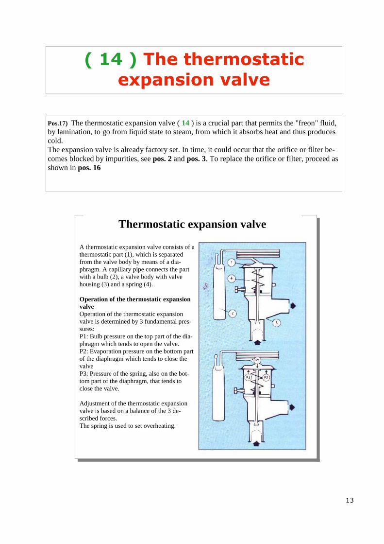
Pos.17) The thermostatic expansion valve ( 14 ) is a crucial part that permits the "freon" fluid, by lamination, to go from liquid state to steam, from which it absorbs heat and thus produces cold. The expansion valve is already factory set. In time, it could occur that the orifice or filter be-comes blocked by impurities, see pos. 2 and pos. 3. To replace the orifice or filter, proceed as shown in pos. 16
Thermostatic expansion valve
A thermostatic expansion valve consists of a thermostatic part (1), which is separated from the valve body by means of a dia-phragm. A capillary pipe connects the part with a bulb (2), a valve body with valve housing (3) and a spring (4). Operation of the thermostatic expansion valve Operation of the thermostatic expansion valve is determined by 3 fundamental pres-sures: P1: Bulb pressure on the top part of the dia-phragm which tends to open the valve. P2: Evaporation pressure on the bottom part of the diaphragm which tends to close the valve P3: Pressure of the spring, also on the bot-tom part of the diaphragm, that tends to close the valve. Adjustment of the thermostatic expansion valve is based on a balance of the 3 de-scribed forces. The spring is used to set overheating.

14
( 14b ) The thermostatic expansion valve
Model T2 “spares”
The T2 - TE2 expansion valves are fitted in refrigeration plants featuring the following MANEUROP (1) compressor models:
15
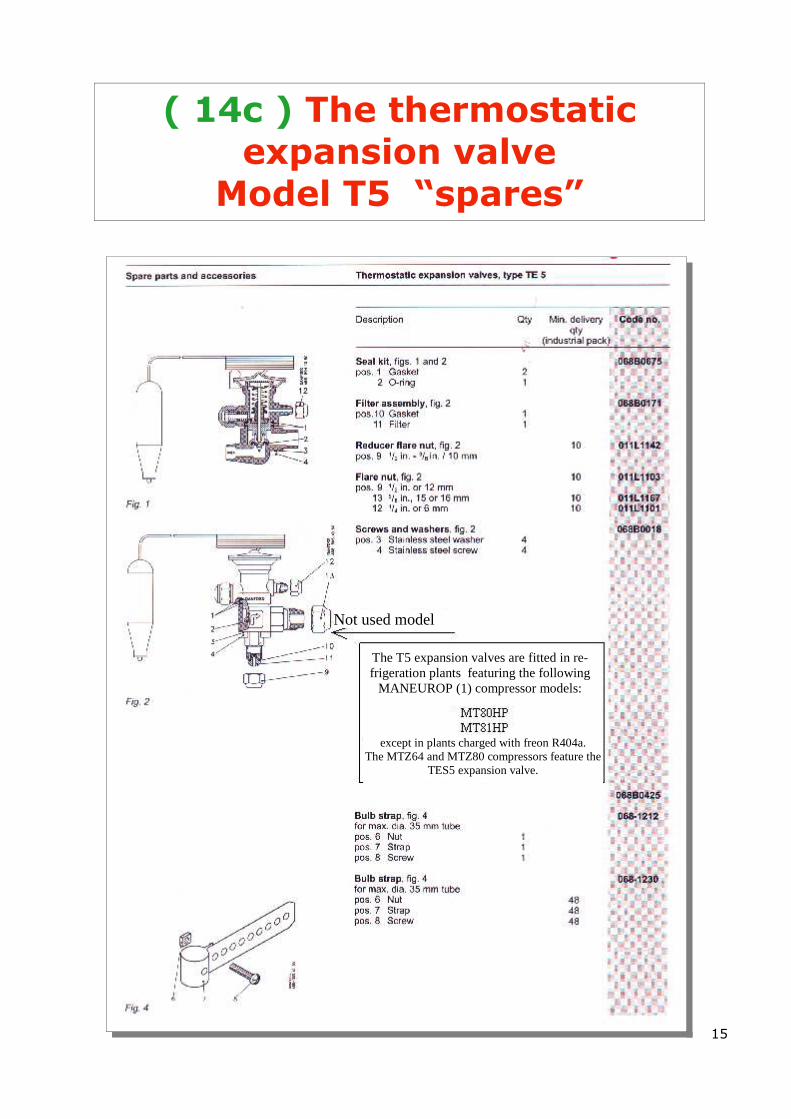
( 14c ) The thermostatic expansion valve
Model T5 “spares”
Not used model
The T5 expansion valves are fitted in re-frigeration plants featuring the following
MANEUROP (1) compressor models:
except in plants charged with freon R404a. The MTZ64 and MTZ80 compressors feature the
TES5 expansion valve.

16
( 14d ) The thermostatic Expansion valve
Model T12 “spares”
The T12 expansion valves are fitted in refrigeration plants featuring the follow-ing MANEUROP (1) compressor models:

17
( 14e ) The thermostatic expansion valve identification
Identification
On the thermostatic part, a coloured label indi-cates the type of coolant to be used by the valve: yellow green yellow with blue stripe lilac silver The letters refer to the type indications used by Danfoss The label shows the type of valve, the evapora-tion temperature range, any MOP point, the cool-ant and the allowed operating pressure (maximum) PB/MWP.
The orifice assembly for the T2 and TE2 is indicated for instance by 02 to indicate the orifice 02. A stamp on the top part of the spring stop plate identifies the orifice assemblies for the TE5, TE12, TE 20. This stamp consists of two parts. That at the top of the plate, eg., TE 12, indicates the type of valve for which the orifice assembly must be used. That at the bottom, eg., 03, indicates the orifice 03 number.

18
( 14f ) The thermostatic expansion valve
setting
Setting
The expansion valve is factory set, which is suitable for most cases. If further setting is required, this can be done by means of the expansion valve adjustment rod. By turning this clockwise, expansion valve overheating can be increased, while by turning anti-clockwise, this overheating is reduced. In the case of the T2/TE2, one turn of the rod changes overheating by about 4 K (°C) at an evaporation temperature of 0°C (field no.)
In the case of the TE5 and larger quantities, one turn of the rod changes overheating by about 0.5 K at an evaporation temperature of 0°C (Field N). In the case of the TE3 and subsequent quan-tities, a turn of the rod changes overheating by about 3 K° at an evaporation temperature of 0°C (R12).
To eliminate evaporator hunting, increase the overheating by turning the rod several times clockwise until it stops. Turn the rod step by step anti-clockwise until hunting starts again. From this position, turn the rod once clockwise (only 1/4 turn for valves T2/TE2 and TKE) At this setting, the refrigera-tor plant does not hunt and evaporation is fully used. A variation of overheating of + 0.5°C is not considered hunting.
19
( 14g ) The thermostatic expansion valve
setting
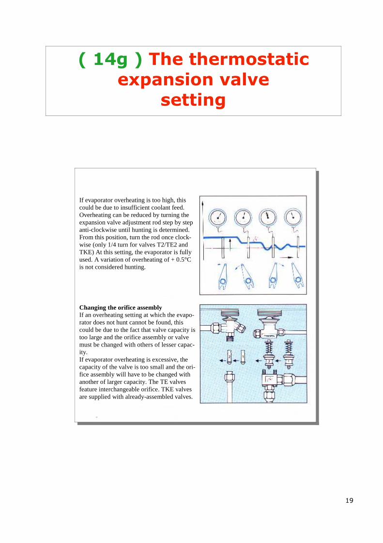
If evaporator overheating is too high, this could be due to insufficient coolant feed. Overheating can be reduced by turning the expansion valve adjustment rod step by step anti-clockwise until hunting is determined. From this position, turn the rod once clock-wise (only 1/4 turn for valves T2/TE2 and TKE) At this setting, the evaporator is fully used. A variation of overheating of + 0.5°C is not considered hunting.
Changing the orifice assembly If an overheating setting at which the evapo-rator does not hunt cannot be found, this could be due to the fact that valve capacity is too large and the orifice assembly or valve must be changed with others of lesser capac-ity. If evaporator overheating is excessive, the capacity of the valve is too small and the ori-fice assembly will have to be changed with another of larger capacity. The TE valves feature interchangeable orifice. TKE valves are supplied with already-assembled valves.
20
( 19 ) The pressure switch valve
Pos.18) The pressure switch valve ( 19 ) WVFX is used in refrigeration plants with water-cooled condensers ( 9 ) to keep a constant condensation pressure with varying loads. The flow of water inside the condenser cools the compressed freon ( RED circuit), which thus returns to its liquid state. This valve can be used with all coolants except R717 (ammonia). The pressure switch valve also regulates the high pressure circuit, see high pressure gauge ( 25 ). Correct pressure during operation should be between 19 and 20 bar.
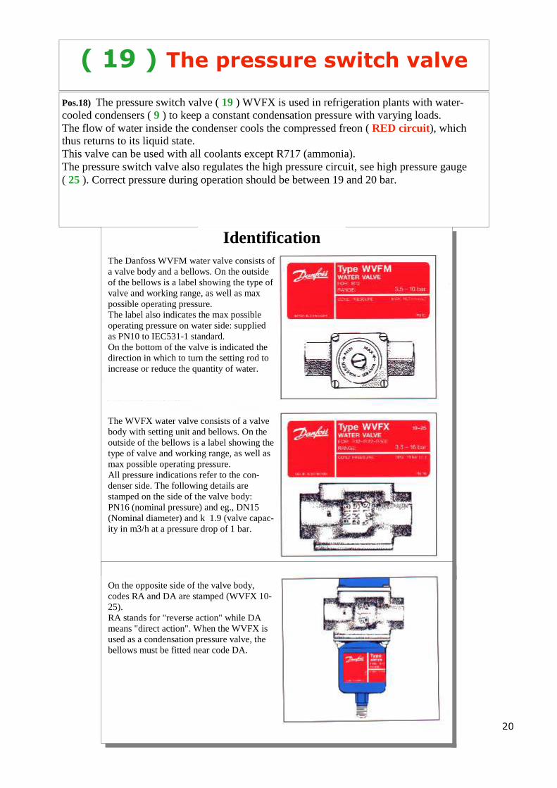
Identification The Danfoss WVFM water valve consists of a valve body and a bellows. On the outside of the bellows is a label showing the type of valve and working range, as well as max possible operating pressure. The label also indicates the max possible operating pressure on water side: supplied as PN10 to IEC531-1 standard. On the bottom of the valve is indicated the direction in which to turn the setting rod to increase or reduce the quantity of water.
The WVFX water valve consists of a valve body with setting unit and bellows. On the outside of the bellows is a label showing the type of valve and working range, as well as max possible operating pressure. All pressure indications refer to the con-denser side. The following details are stamped on the side of the valve body: PN16 (nominal pressure) and eg., DN15 (Nominal diameter) and k 1.9 (valve capac-ity in m3/h at a pressure drop of 1 bar.
On the opposite side of the valve body, codes RA and DA are stamped (WVFX 10-25). RA stands for "reverse action" while DA means "direct action". When the WVFX is used as a condensation pressure valve, the bellows must be fitted near code DA.

21
( 19b ) The pressure switch valve changing
Pos.19) Before changing the pressure switch valve, always make sure that the supply capillary is not blocked. This capillary is connected to a 1/4 stopcock ( 20 ) which detects compression pressure (RED circuit) Once the valve has been found to be faulty, the change can be made: a close the 1/4 stopcock ( 20 ), screw up the pin inside the black cap clockwise, see the il-
lustration on page 5. b make sure the water is shut off c unscrew the union below the pressure switch valve. A small amount of freon will escape d make the change e once the new valve has been fitted, make sure there are no leaks in the water circuit. f before fastening the union back on, bleed by allowing a small amount of freon vapour to
come out g screw the union back on using a counter-spanner so as not to force the body of the pres-
sure switch valve h after making the change, run the refrigeration plant i at this point, the high pressure must be regulated at 20 bar and the pressure switch valve
must be reset, see illustration
Setting
The WVFM and WVFX valves are set to obtain the desired condensation pressure. By turning the rod to the right, a lower pres-sure is achieved, while turning it to the left, a higher pressure is achieved. For the ap-proximate setting of WVFM and WVFX the value of graduated scale 1-5 can be used. Value 1 corresponds to about 2 bar and value 5 to about 17 bar. Note: the setting range values indicate the moment of open-ing. To have a fully open valve, condenser pressure must be above 3 bar.

22
( 7 ) The check valve At the heat regeneration battery exit
Pos.20) The purpose of this check valve ( 7 ) is, during the cooling stage, to close the circuit of the heat regeneration battery exit ( 6 ) so the freon is forced to enter the condenser tank ( 9 ). Pos.21) Without this check valve during the cooling stage, a large quantity of freon would end up in the heat regeneration battery ( 6 ) and affect proper operation during cooling.
( 5 ) The check valve Downstream of the cooling solenoid valve ( 3 )
Pos.22) When the refrigeration plant is stopped, this check valve ( 5 ) prevents the freon from overflowing from the condenser tank ( 9 ) into the compressor ( 1 ). Pos.23) Without this check valve, when the refrigeration plant is stopped, all the freon would overflow into the compressor. On starting the plant again, there would be a lot of freon inside the compressor with risk of damaging the compressor valves.
NRV = CHECK VALVE

23
( 23 ) Low pressure gauge
Symptom Proper adjustment Check
• Pressure too low • The plant stops and the
minimum pressure switch ( 21 ) engages
Proper operating pressure dur-ing drying is between 4 and 5 bar, while during cooling, it starts at 3 bar and ends at about 2 bar.
1. Make sure the freon charge is correct.
2. Make sure the dehydration fil-ter ( 11 ) is not blocked
3. Make sure the expansion valve ( 14 ) is not blocked or run-down
4. Check the evaporation battery ( 15 ). It could be dirty and pre-vent heat exchange
Pos.24) While the refrigeration plant is operating, the low pressure gauge displays the intake pressure (GREEN circuit)
( 25 ) The high pressure gauge
Pos.25) When the refrigeration plant is operating, the high pressure gauge display the com-pression pressure (RED circuit)
Symptom Proper adjustment Check
• Pressure too high • The plant stops and the
high pressure switch ( 22 ) engages
• The proper operating pres-sure during all operating stages is between 19 and 20 bar.
1. Make sure the water inside the condenser tank ( 9 ) is circu-lating properly
2. Make sure the pressure switch valve ( 19 ) is not faulty.
3. Make sure the condenser tank coil ( 9 ) is not affected by scale.
24
( 21 ) The low pressure switch
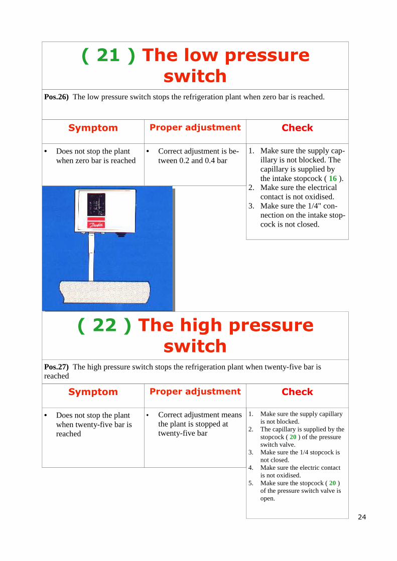
Pos.26) The low pressure switch stops the refrigeration plant when zero bar is reached.
Symptom Proper adjustment Check
• Does not stop the plant when zero bar is reached
• Correct adjustment is be-tween 0.2 and 0.4 bar
1. Make sure the supply cap-illary is not blocked. The capillary is supplied by the intake stopcock ( 16 ).
2. Make sure the electrical contact is not oxidised.
3. Make sure the 1/4" con-nection on the intake stop-cock is not closed.
( 22 ) The high pressure switch
Symptom Proper adjustment Check
• Does not stop the plant when twenty-five bar is reached
• Correct adjustment means the plant is stopped at twenty-five bar
1. Make sure the supply capillary is not blocked.
2. The capillary is supplied by the stopcock ( 20 ) of the pressure switch valve.
3. Make sure the 1/4 stopcock is not closed.
4. Make sure the electric contact is not oxidised.
5. Make sure the stopcock ( 20 ) of the pressure switch valve is open.
Pos.27) The high pressure switch stops the refrigeration plant when twenty-five bar is reached

25
Settings
Low pressure switch: Set the starting pressure (CUT IN) on the pressure range scale (A). Regulate the differential (DIFF) on the differential val-ues scale (B). Stop pressure = CUT IN less DIFF. High pressure switch Set the stop pressure (CUT OUT) on the pressure range scale (A). Regulate the differential (DIFF) on the differential val-ues scale (B). Start pressure = CUT OFF less DIFF: Always remember that the scales are only approximate.
Checking contact operation
After making connections and with the plant at normal operating pressure, manu-ally check contact operation. Depending on the pressure and setting of the bellows, the rocker must be either pressed down or pushed up. During the test, all reset mechanisms are inoperative. On the single pressure switches: left, up. On double pressure switches: left to check low pressure, or right down to check high pressure. Important: Operation of the contacts of a KP pressure switch must never be checked by operating the rocker to the right and up. Failure to follow this rule could result in pressure switch misadjustment and, at worst, damage the appliance.

26
( 21-22 ) The pressure switch “spares”

27
( 9 ) The condenser tank
Pos.28) The condenser tank performs two basic functions: the first is to condense the coolant from compressed vapour to liquid state (it yields heat to a coolant, which in our case is the water and thus returns to liquid state). The second is to accumulate the liquid coolant in the bottom part of the tank so as to always have a sufficient quantity of coolant. Pos.29) The possibility exists of the coil inside the tank, after years of operation, being af-fected by scale. For the refrigeration plant, this problem results in a rise in compression pres-sure (RED circuit) until a pressure of twenty-five bars is reached and the water alarm trips. Pos.30) Light acids exist on the market for removing scale. If however the scale has badly affected the coil, the condenser tank ( 9 ) will have to be replaced.

28
( 9 ) The condenser tank changing
Pos.30) To replace the condenser tank, proceed as follows: a Remove the coolant from the refrigeration plant b Remove the hydraulic section c Unscrew the rotablock corner ( 8 ) d Loosen the liquid rotablock stopcock ( 10 ) e At this point, the tank can be changed f Fit the hydraulic section back on, avoiding any water leaks g Screw the rotablock corner ( 8 ) and the rotablock stopcock ( 10 ) back on h Replace the dehydration unit filter ( 11 ) and the liquid indicator ( 12 ) i Create vacuum in the refrigeration plant j Recharge with freon R22 from intake ( 16 ) of the compressor ( 1 ) k When charging the refrigeration plant, it is best to operate this in drying phase. Inject the
freon R22 until the liquid indicator ( 12 ) stops displaying bubbles. l Check adjustment of the pressure switch valve ( 19 ), see pos. 18 m At this point replacement has been made n We recommend the technician make a number of washes for final testing of the replace-
ment made.
( 8 ) Rotalock corner
Pos.30bis) the rotalock corner ( 8 ) is a component fitted in the condenser tank ( 9 ) in the compression circuit (RED circuit) with freon entry still in vapour state.

29
( 9a ) The condenser tank Fitted to plants with compressors:
MANEUROP-MT40JH
MODEL

30
( 9b ) The condenser tank Fitted to plants with compressors:
MANEUROP-MT50HK, MT65HM, MT81HP
65 65
MODEL

31
( 9c ) The condenser tank Fitted to plants with compressors:
MANEUROP-MT100HS
MODEL

32
( 15 ) The evaporator battery
Pos.31) The production of cold with mechanical plant is based on physical laws that regulate the evaporation and condensation of a fluid. In the transition from liquid state to vapour state, a fluid absorbs heat and therefore produces cold. This transformation occurs in a heat exchanger called an evaporator ( 15 ) Pos.32) In the refrigeration plant for dry cleaning, the evaporator battery ( 15) re-condenses the solvent vapours inside the air circuit. To ensure smooth operation, the evaporator must always be kept clean, so periodical cleaning is advisable.
( 6 ) The heat regeneration battery
Pos.33) In its compression circuit (RED circuit), the refrigeration plant contains a very hot compressed fluid in vapour state. These "kcal" calories can be used to help the heating ele-ments or steam circuits on the dry cleaning machine. Pos.33) For smooth operation, this battery must also be kept clean

33
The artic-line coil
Pos.34) The ARTIC-LINE COIL is a circuit for solvent cooling fitted on request on the tradi-tional refrigeration plant which consists of:
1. ARTIC-LINE COIL is a finned coil in tin or nickel-plated copper. This coil is an evaporator, see pos. 31.
2. Expansion valve ( 17 ) mod. DANFOSS T2 without balance. This valve has the same features as the TEX2 ( 14 ), see page 13, with the only difference that it is without balance. The balance is a 1/4" sae connection located on the side of the valve that regulates correct freon distribution in the evaporator battery ( 15 ). In this case, the evaporator is not a battery but a coil and for this reason, the balance serves no pur-pose.
3. Solenoid valve ( 18 ) mod. DANFOSS EVR6 4. This circuit is normally connected to the refrigeration plant by means of the AEREO-
QUIP quick couplings, see illustration below. These couplings make it possible to disconnect the entire coil block without losing coolant.
Pos.35) The refrigeration plant is available in two versions: monobloc and condensing unit. The Aereo-quip coupling is fitted in the condensing unit plant. This isolates components requiring periodical servicing without losing coolant. These components are: evaporator battery ( 15 ), heat regeneration battery ( 6 ), artic-line coil. To find the coupling model, check the diameter of the pipe to which it is fitted and make reference to the above illustration.
AEREOQUIP COUPLING
MALE COUPLING FEMALE COUPLING

SERVICING PLANS WITH R404a PAGE 40
CHARGING WITH R404a PAGE 42
R404a SUGGESTION PAGE 41
USEFUL ADVICE FOR SERVICING REFRIGERATOR PLANTS CHA RGED WITH FREON R404a PAGE 45
REFRIGERATION PLANT FOR DRY-CLEANING—KEY PAGE 2
REFRIGERATION PLANT FOR DRY-CLEANING CHARGED WITH FREON R404a—KEY PAGE 35
AEREOQUIP QUICK COUPLING PAGE 33
THE ARTIC-LINE COIL S6 - S10 - S25 PAGE 33
THE R404a COOLANT AND TYPES OF ESTER AND MINERAL OILS PAGE 39
( 1 ) THE MANEUROP COMOPRESSOR PAGE 3
( 1 ) THE MANEUROP COMPRESSOR—OIL TYPE PAGE 39
( 1 ) THE MANEUROP COMPRESSOR—1 CYLINDER TYPE PAGE 3 / A
( 1 ) THE MANEUROP COMPRESSOR—2 CYLINDER TYPE PAGE 3 / B
( 1 ) THE MANEUROP COMPRESSOR—3 CYLINDER TYPE PAGE 3 / C
( 1b ) THE MANEUROP COMPRESSOR—TROUBLESHOOTING PAGE 4
( 1 ) THE MANEUROP COMPRESSOR—CHANGING PAGE 4 / A
( 1 ) THE MTZ FREON R404a MANEUROP COMPRESSOR PAGE 36
( 1 ) THE MTZ MANEUROP COMPRESSOR—CHANGING PAGE 37
( 2 ) THE COMPRESSION COCK PAGE 5
( 3 ) ( 4 ) ( 13 ) ( 18 ) MODELS OF SOLENOID VALVES FITTED PAGE 6
( 3 ) EVR10 SOLENOID VALVE—COOLING PAGE 7
( 4 ) EVR10 SOLENOID VALVE—DRYING PAGE 6
( 5 ) THE NRV-12-S NRV-16-S NRV-22-S CHECK VALVE PAGE 22
( 6 ) THE HEAT REGENERATION BATTERY PAGE 32
( 7 ) THE NRV-12-S NRV-16-S NRV-22-S CHECK VALVE PAGE 22
( 8 ) ROTALOCK CORNER PAGE 28
( 9 ) THE CONDENSER TANK PAGE 27
( 9 ) THE CONDENSER TANK—CHANGING PAGE 28
( 9a ) THE CONDENSER TANK - MODEL FOR MT40 PAGE 29
( 9b ) THE CONDENSER TANK - MODEL FOR MT65 - MT81 PAGE 30
( 9c ) THE CONDENSER TANK - MODEL FOR MT100 PAGE 31
( 10 ) THE LIQUID ROTALOCK COCK PAGE 5
( 11 ) THE DEHYDRATION UNIT FILTER DN163—DN164—DN305 MODELS FITTED PAGE 9 — 10
( 11d—12 ) CHANGING THE DEHYDRAION FILTER UNIT AND LIQUID INDI CATOR PAGE 12
( 11d—12 ) CHANGING THE DEHYDRAION FILTER UNIT AND LIQUID INDI CATOR IN FREON R404a PLANTS PAGE 38
( 12 ) LIQUID INDICATOR SGN10—SGN12—SGN16 PAGE 11
( 13 ) LIQUID SOLENOID VALVE EVR6—EVR10 PAGE 7
( 14 ) THE THERMOSTATIC EXPANSION VALVE TX2—TeX2—TeX5—TeX12 PAGE 13
( 14b ) THE THERMOSTATIC EXPANSION VALVE T2 SPARES PAGE 14
( 14c ) THE THERMOSTATIC EXPANSION VALVE T5 SPARES PAGE 15
( 14d ) THE THERMOSTATIC EXPANSION VALVE T12 SPARES PAGE 16
( 14e ) THE THERMOSTATCI EXPANSION VALVE—IDENTIFICATION PAGE 17
( 15 ) EVAPORATOR BATTERY PAGE 32
( 16 ) ROTALOCK INTAKE COCK PAGE 5
( 17 ) ARTIC-LINE EXPANSION VALVE TE2 PAGE 33
( 18 ) ARTIC-LINE SOLENOID VALVE EVR6 PAGE 7
( 19 ) THE PRESSURE SWITCH VALVE WVFX PAGE 20
( 19b ) THE PRESSURE SWITCH VALVE—CHANGING PAGE 21
( 20 ) 1/4 COCK FOR SUPPLYING THE PRESSURE SWITCH VALVE PAGE 5
( 21 ) THE LOW-PRESSURE PRESSURE SWITCH KP 1 PAGE 24
( 22 ) THE HIGH-PRESSURE PRESSURE SWITCH KP 5 - KP 7W PAGE 24
( 21-22 ) THE SPARES PRESSURE SWITCH PAGE 26
( 23 ) THE LOW-PRESSURE PRESSURE GAUGE -1 +15 Bar PAGE 23
( 24 V ) THE COIL IP-67 PAGE 8
( 25 ) THE HIGH-PRESSURE PRESSURE GAUGE -1 +32 Bar PAGE 23
( 26 ) CONDENSER PLATE EXCHANGER PAGE 43
( 26 ) CONDENSER PLATE EXCHANGER—CLEANING PAGE 43
( 26 ) CONDENSER PLATE EXCHANGER—MODELS PAGE 44
CONTENTS

3 / A
( 1 ) The MANEUROP
Compressor — 1 cylinder type
( 1 ) The MANEUROP
compressor — 2 cylinder type
3 / B

( 1 ) The MANEUROP
compressor — 3 cylinder type
3 / C

4 / A
( 1 ) The Compressor
Changing
Pos. 3b) To replace the compressor (1) proceed as follows: a Make sure the power supply is disconnected b Remove the power contacts inside the compressor terminal board c Close the compression cock (2) and the intake cock (16) by turning clockwise, see page 5 d Loosen the intake cock (16) by turning anticlockwise until the freon inside the compressor
can be heard escaping. Wait for all the freon to escape and then finish loosening the cock. e Loosen the compression cock (2) by turning anticlockwise until the freon inside the com-
pressor can be heard escaping. Wait for all the freon to escape and then finish loosening the cock.
f Remove the three retention bolts at the base of the compressor. g At this point, the faulty compressor can be removed. h Prepare the new compressor. Fit the three vibration rubbers provided to the base. i Fit the new compressor and fasten with the bolts "see point f" j Remove the caps at intake and compression k Tighten the aspiration cock (16) l Tighten the compression cock (2) m At this point, connect a vacuum pump to the connector at the side of the compressor to re-
move any humidity n Inject freon under pressure and disconnect the vacuum pump o Turn the intake cock (16) and compression cock (2) anticlockwise p Reconnect the power contacts q At this point we recommend changing the dehydration unit filter (11) see page 12 r After terminating the operation, make sure the refrigeration plant does not require freon by
looking at the liquid indicator (12) see page 11 s If there is not enough freon, add by connecting the canister to the connector on the side of
the compressor, or to the intake cock. t When charging the refrigeration plant, always run this in drying phase and inject the freon
R22 until the liquid indicator (12) stops showing bubbles. u The technician should perform a number of washes to test the plant after changing the
compressor.

34
REFRIGERATION PLANTS FOR
DRY-CLEANING MACHINES
CHARGED WITH R404a
COOLANT

Key to refrigeration plant for
dry-cleaning machines charged with
R404a
35
ARTIC LINE COIL
1) Maneurop compressor 2) Rotalock compression cock 3) Cooling solenoid valve 4) Drying solenoid valve 5) Check valve 6) Heat regeneration battery 7) Check valve 8) Rotalock corner 9) freon receiver tank 10) Liquid Rotalock cock 11) Dehydration unit filter 12) Liquid indicator 13) Liquid solenoid valve 14) "batt. EV" expansion valve 15) Evaporator battery 16) Rotalock intake cock 17) "artic line" expansion valve 18) artic line" solenoid valve 19) water pressure switch valve 20) 1/4 cock for pressure switch valve 21) Low pressure switch 22) High pressure switch 23) Low pressure gauge 24 V) 24 V 50 Hz coils 25) High pressure gauge 26) Plate exchanger

( 1 ) The compressor
The refrigeration plants charged with new ecological freon R404a feature MTZ model com-pressors:
Mod. Power MTZ40JH - H.P. 3,25 MTZ50HK - H.P. 4,00 MTZ51HK - H.P. 4,00 MTZ64HM - H.P. 5,00 MTZ65HM - H.P. 5,00 MTZ80HP - H.P. 6,50 MTZ81HP - H.P. 6,50 MTZ100HS - H.P. 8,50 MTZ125HU - H.P.10,00
36

( 11d – 12c ) Replacing the dehydration unit filter and the liquid indicator of plants char-
ged with freon R404a
Pos.37) To replace the dehydration unit filter ( 11) and the liquid indicator ( 12) in plants with freon R404a, proceed as follows: a Close the liquid cock ( 10 ) rotalock valve, see page 5 b Switch on the refrigeration plant until an intake pressure of 0.2 bar is achieved [seen on
the low pressure gauge ( 23 ) ] c The compressor stops [the low pressure switch trips ( 21 )] d Close the intake cock ( 16 ) rotalock valve, see page 5 e At this point the filter and indicator can be changed. This job should be done as quickly as
possible to prevent penetration of humidity. IMPORTANT: the conical copper seals of the filter and indicator retention unions must be changed every time replacement is made.
f Tighten the unions well (Dutch unions) g Open the liquid cock ( 10 ) and intake cock ( 16 ) again. h Using a leak detector make sure there are no leaks. After making the replacement, operate the refrigeration plant.
38

37
( 1 ) The MTZ compressor changing
Pos.36) To replace the compressor (1) proceed as follows: a Make sure the power supply is disconnected b Remove the power contacts inside the compressor terminal board c Close the compression cock (2) and the intake cock (16) by turning clockwise, see page 5 d Loosen the intake cock (16) by turning anticlockwise until the freon inside the compressor
can be heard escaping. Wait for all the freon to escape and then finish loosening the cock. e Loosen the compression cock (2) by turning anticlockwise until the freon inside the com-
pressor can be heard escaping. Wait for all the freon to escape and then finish loosening the cock.
f Remove the three retention bolts at the base of the compressor. g At this point, the faulty compressor can be removed. h Prepare the new compressor. Fit the three vibration rubbers provided to the base. i Fit the new compressor and fasten with the bolts "see point f" j Remove the caps at intake and compression (caution: the MTZ compressor is lubri-
cated with ester oil and should therefore be left without caps for as short a time as possible to prevent absorption of humidity)
k Tighten the intake cock (16) l Tighten the compression cock (2) m At this point, connect a vacuum pump to the connector at the side of the compressor to re-
move any humidity n Inject liquid freon R404a (to maintain characteristics, make sure liquid R404a is in-
jected) and disconnect the vacuum pump o Turn the intake cock (16) and compression cock (2) anticlockwise p Reconnect the power contacts q At this point we recommend changing the dehydration unit filter (11), see page 37 r After terminating the operation, make sure the refrigeration plant does not require freon
by looking at the liquid indicator (12), see page 11 s If there is not enough freon, add by connecting the canister to the connector on the side of
the compressor, or to the intake cock. t When charging the refrigeration plant, always run this in drying phase and inject the liq-
uid R404a freon (be careful when injecting liquid that the compressor does not frost up by regulating the freon canister stopcock) until the liquid indicator (12) stops show-ing bubbles.
u The technician should perform a number of washes to test the plant after changing the compressor.

39
The R404a coolant
R404a is a coolant that does not damage the environment and complies with the stringent regulations intended to protect the ozone layer. Together with appropriate compo-nents such as, for example, the compressor, the thermostatic expansion valve and the dehydration unit filter, R404a is the ideal coolant recommended by legislators instead of R22, R505 coolant.
R404a requires very few special compo-nents. Among these, special mention must be made of refrigeration compressors lubri-cated with ester oil. These have been chosen because they can be mixed with the R404a, thereby ensuring good lubrication and long compressor life. The combination of R404a and ester oil is more water absorbing than the combination of R22 and mineral oil. A special dehydration unit filter is therefore required featuring a molecular sieve suitable for the molecular structure of R404a.
The type of oil for MANEUROP MT/MTZ compressors

40
After-sales service on R404a plants
Basically speaking, all R404a refrigeration plant installation precautions must be taken. The mains rules in this case too are: Absolute cleanliness Pipe brazing must be performed in nitrogen atmosphere For the different groups of coolants, tools must be used with special markings.
To check for R134a circuit leaks, several methods exist: many manufacturers offer electronic leak detection equipment. In this case the leak is indicated acoustically. An-other option is the search with a UV (ultra-violet) lamp that highlights the leak of a mix consisting of ester oil and an additive previ-ously placed in the coolant. The old method of using an open-flame lamp cannot be used with R404a because this coolant does not contain chlorine.
Even though R404a is not toxic nor harmful for the ozone layer, it is best retrieved for economic and environmental reasons. As for R22, manufacturers have designed and built mobile equipment featuring vacuum pumps, able to retrieve, recycle, empty and recharge plants with R404a. These appliances, built for R404a can only be used with this type of gas. If polluted by chlorine-based coolants or by detergent agents, the R404a must be de-stroyed.
41
Suggestions
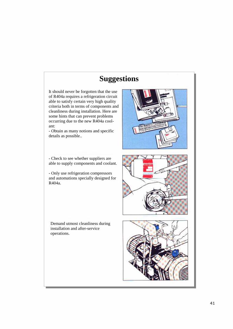
It should never be forgotten that the use of R404a requires a refrigeration circuit able to satisfy certain very high quality criteria both in terms of components and cleanliness during installation. Here are some hints that can prevent problems occurring due to the new R404a cool-ant: - Obtain as many notions and specific details as possible..
- Check to see whether suppliers are able to supply components and coolant. - Only use refrigeration compressors and automations specially designed for R404a.
Demand utmost cleanliness during installation and after-service operations.
42
Charging with R404a
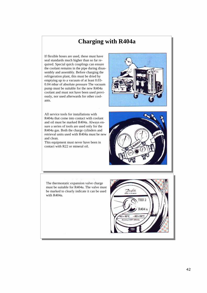
If flexible hoses are used, these must have seal standards much higher than so far re-quired. Special quick couplings can ensure the coolant remains in the pipe during disas-sembly and assembly. Before charging the refrigeration plant, this must be dried by emptying up to a vacuum of at least 0.03-0.04 mbar of absolute pressure The vacuum pump must be suitable for the new R404a coolant and must not have been used previ-ously, nor used afterwards for other cool-ants.
All service tools for installations with R404a that come into contact with coolant and oil must be marked R404a. Always en-sure a series of tools are used only for the R404a gas. Both the charge cylinders and retrieval units used with R404a must be new and clean. This equipment must never have been in contact with R22 or mineral oil.
The thermostatic expansion valve charge must be suitable for R404a. The valve must be marked to clearly indicate it can be used with R404a.

43
( 26 ) Plate exchanger “condenser”
Pos.38) Plants charged with freon R404a at high pressure are adjusted at 22-23 bar and to en-sure the same water consumption and same characteristics as freon R22 a plate exchanger is fitted ( 26 ). Because the ducts inside this exchanger are very narrow, the water has to be filtered very well. In plants where hard water is used, such ducts are liable to blockage. These must there-fore be periodically cleaned as indicated below.
NOTE: On our refrigeration plants charged with freon R404a, on request, condenser tanks "with internal finned coil" can be fitted, like those fitted to plants charged with freon R22. The difference is: In the case of plants with freon 404a, the finned coil inside the tank has a larger surface than the coil of the tank with freon R22. To consume the same amount of water as a freon R22 refrigeration plant, during condensation, freon R404a requires greater heat exchange.
Cleaning the plate exchanger In some applications, there is a strong tendency to blockage. For example, when very hard water is used. The exchanger can always be cleaned by circulating a detergent liquid (CIP). Use a tank containing a light acid, 5% phosphoric acid or, if the exchanger is cleaned regularly, 5% oxalic acid. Allow the deter-gent to circulate inside the exchanger. For successful cleaning, the flow rate of the detergent must be at least 1.5 times normal working rate. Rinse well with water to remove all traces of acid before starting up the plant again. Perform these cleaning operations at regular intervals.
CIP Chemical cleaning device Heat exchanger Weak acid

44
( 26 ) Plate exchanger models
WATER INLET
fitted exchanger models:
refrigeration plants with MANEUROP MTZ40-51 compressor: model fitted SWEP - B08-10
refrigeration plants with MANEUROP MTZ 64-81 compressor: model fitted SWEP - B15-30

Useful suggestions for jobs done on
refrigerators charged with R404a
a) The refrigeration plants charged with freon R404a feature compressors lubricated with ester oils. Ester-base oil is much more water-absorbing than mineral oil. "used with freon R22" Always be very careful not to leave the new compressor without caps. "in intake and com-pression" When coming into contact with atmospheric pressure, ester-base oil manages to absorb plenty of humidity in just a few minutes.
b) freon R404a is a mixture made up of: 44% R125 52% R143A 4% R134A These three types of freon have different molecular structures and when any freon R404a escapes from the refrigeration plant "due to leaks or maintenance jobs", especially of the gaseous vapour type, the freon R404a coolant no longer has the same percentages of the above-listed elements. The remaining freon still inside the refrigeration plant is always a coolant gas, but no longer has the characteristics of freon R404a. Example of maintenance job: replacement of the fridge compressor, or repair of a freon leak. In both cases, a fairly large quantity of R404a escapes from the plant. Once the compressor has been changed or the leak has been repaired, the possibility exists that the freon R404a still inside the re-frigeration plant no longer has the same characteristics. "the three types of freon making it up have structures of different molecular size and the type of freon with the smallest molecules will have escaped most". After changing the compressor or repairing the leak, on starting up the refrigeration plant again, the technician must necessarily offset the freon that has escaped by injecting R404a. Once the techni-cian has finished the job and, for safety's sake, checks to see that everything is working properly, he will notice the refrigerator no longer has its original features, e.g., longer drying times, different re-frigeration yields, reading of pressure gauges no longer compatible in degrees°, possible intake overheating and greater water consumption and may have to adjust the thermostatic and pressure switch valves to make it operate in some way. It is therefore advisable, both when replacing a compressor or repairing a freon R404a leak to:
1. Remove the freon still in the refrigeration plant 2. Change the dehydration unit filter and liquid indicator 3. Create a vacuum in the refrigeration plant 4. Re-charge with new freon R404a being very careful to inject only liquid
"NO VAPOUR GAS".
45