reflex level gauge - igema.com · the reflex level gauge lg40-cs is a direct water level gauge...
TRANSCRIPT

Reflex Level Gauge LG40-CS
D-02-B-31946-EN-0.doc
Ausgabe 07/2017

-Table of contents-
1. Health and safety instructions 4-5 1.1 General health and safety instructions ........................................ 4 1.2 Unit-specific safety instructions .................................................. 5 1.3 Exclusion of liability .................................................................. 5 2. Important information 6
2.1 Intended use ........................................................................... 6
3. Explanations 6
3.1 Scope of supply ........................................................................ 6 3.2 System description ................................................................... 6 3.3 Function .................................................................................. 6 4. Technical data 7-8
4.1 Versions .................................................................................. 7 4.2 Type of connection ................................................................... 8 4.3 Materials ................................................................................. 8 4.4 Application limits ...................................................................... 8 4.5 Corrosion resistance ................................................................. 8 4.6 Identification plate / Marking ..................................................... 8 5. Construction 9
6. Assembly 9-10
6.1 Version with flange ................................................................... 9 6.2 Version with butt welding end .................................................. 10 6.3 Heat treatment of weld seams ................................................. 10 6.4 Drain piping ........................................................................... 10 7. Commissioning 10-11
7.1 Commissioning of unit together with the boiler ........................... 10 7.2 Commissioning of unit if boiler is already in operating condition ... 10 7.3 Re-tightening of screws ........................................................... 11
2

8. Maintenance 11-12
8.1 Leakage ................................................................................ 11 8.2 Cleaning of glasses.. ............................................................... 11 8.3 Cleaning and purging of level gauge ......................................... 12 8.4 Exchange of glass ................................................................... 12 8.5 Assembly .............................................................................. 12 8.6 Tightening torques.................................................................. 12 9. Shutoff valves 13-16
9.1 General information and operating instructions .......................... 13 9.2 Construction ..................................................................... 14-15 9.3 Commissioning ....................................................................... 15 9.4 Maintenance .......................................................................... 16 9.5 Assembly .............................................................................. 16 10. Drain valve 17-18
10.1 Construction .......................................................................... 17 10.2 Assembly .............................................................................. 17 10.3 Commissioning ....................................................................... 17 10.4 Maintenance .......................................................................... 18 11. Case of Damage 18 12. Spare parts 18-19
12.1 Reflex level gauge .................................................................. 18 12.2 Shutoff valve ......................................................................... 19 12.3 Drain valve ............................................................................ 19 13. Decommissioning 20
13.1 Disposal ................................................................................ 20 14. Supplement 20-22 14.1 Warranty ............................................................................... 20
3
General health and safety instructions
1. Avoidance of danger for persons and property • Only use unit for intended purpose. • No additional mountings and modifications on the unit without our approval. • Adhere to the standards for prevention of accidents and to the plant specific safety regulations. • Read and observe installation and operating instructions. 2. Application limits Only use this unit according to these operating instructions and to the parameters agreed upon in the delivery contract (see identification plate) including the agreed operating conditions. 3. Avoidance of danger and damages • Distribute these mounting and operating instructions to appropriate department “arrival
of goods, works transport, mounting, commissioning and maintenance”. • When passing the unit to a third party, these mounting and operating instructions must
be enclosed in the national language of this third party. • Only skilled and qualified personnel with special work order may work on the unit,
which must be free of pipeline stress! • Carefully read, observe and preserve these mounting and operating instructions. • Observe and adhere to the precautions marked in bold characters in the
sections of these mounting and operating instructions! • Avoid shocks and impacts during transport, which could damage the unit. • In case of intermediate storage take care for a dry and appropriate place where the
unit cannot be damaged. 4. Marking In these mounting and operating instructions, the safety instructions are specially marked with the following symbols:
means danger to life and/or serious property damage in case of non-observance. Never ignore!
Danger means that you must pay special attention to the technical relationships.
Attention
4

Unit-specific safety instructions
The fitting is under pressure during operation! If flange connections, screw plugs or stuffing boxes are unfixed, hot water and steam will escape. Carry out assembly and maintenance works only if plant is completely pressureless! The fitting is hot during operation! Severe burns on hands and arms are possible. Wait until the unit has cooled before carrying out assembly and maintenance works! Severe burns and scaldings on the whole body are possible! Wait until the unit has cooled. In case of opening and disassembling the unit, residual
medium can escape. Further evaporation is also possible on pressureless plant. Sharp-edged interior parts can cause cutting damages on the hands! Always wear work gloves when exchanging packing, valve seat and valve cone!
Exclusion of liability The IGEMA GmbH Mess- und Regelsysteme does not accept liability when a/m regulations, instructions and warning indications are not observed and adhered to. The operator is responsible for modifications on a unit of IGEMA (if they are not explicitly specified in the mounting and operating instructions).
5
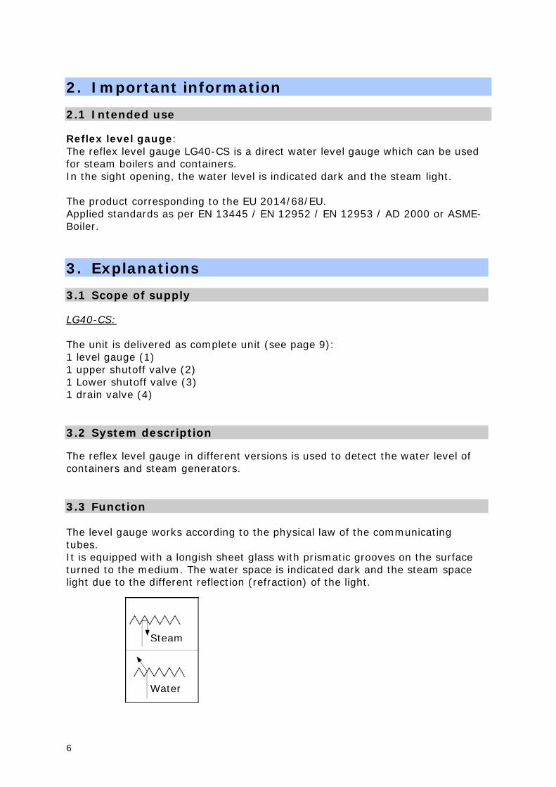
2. Important information 2.1 Intended use Reflex level gauge: The reflex level gauge LG40-CS is a direct water level gauge which can be used for steam boilers and containers. In the sight opening, the water level is indicated dark and the steam light. The product corresponding to the EU 2014/68/EU. Applied standards as per EN 13445 / EN 12952 / EN 12953 / AD 2000 or ASME-Boiler.
3. Explanations 3.1 Scope of supply LG40-CS: The unit is delivered as complete unit (see page 9): 1 level gauge (1) 1 upper shutoff valve (2) 1 Lower shutoff valve (3) 1 drain valve (4) 3.2 System description The reflex level gauge in different versions is used to detect the water level of containers and steam generators. 3.3 Function The level gauge works according to the physical law of the communicating tubes. It is equipped with a longish sheet glass with prismatic grooves on the surface turned to the medium. The water space is indicated dark and the steam space light due to the different reflection (refraction) of the light.
Steam
Water
6
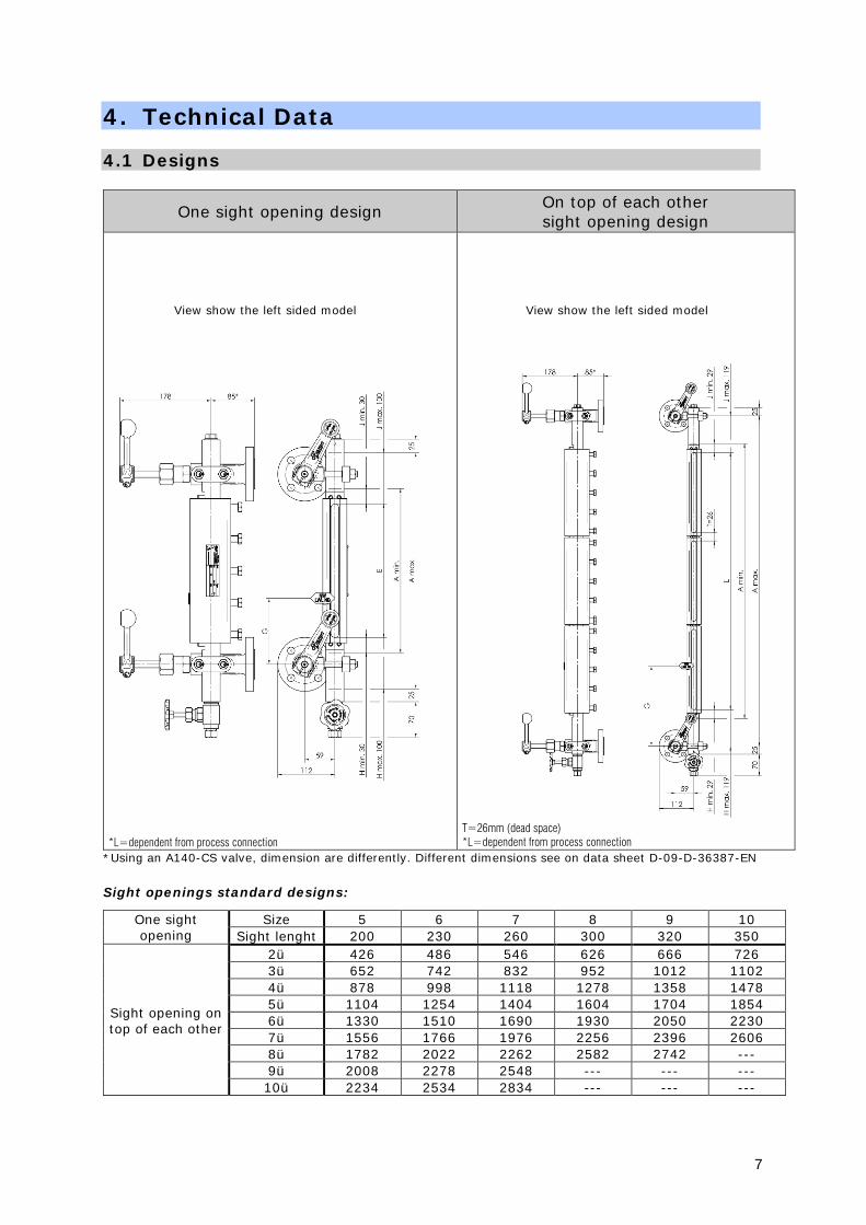
4. Technical Data 4.1 Designs
One sight opening design On top of each other sight opening design
*L=dependent from process connection
T=26mm (dead space) *L=dependent from process connection
*Using an A140-CS valve, dimension are differently. Different dimensions see on data sheet D-09-D-36387-EN Sight openings standard designs:
One sight opening
Size 5 6 7 8 9 10 Sight lenght 200 230 260 300 320 350
Sight opening on top of each other
2ü 426 486 546 626 666 726 3ü 652 742 832 952 1012 1102 4ü 878 998 1118 1278 1358 1478 5ü 1104 1254 1404 1604 1704 1854 6ü 1330 1510 1690 1930 2050 2230 7ü 1556 1766 1976 2256 2396 2606 8ü 1782 2022 2262 2582 2742 --- 9ü 2008 2278 2548 --- --- --- 10ü 2234 2534 2834 --- --- ---
View show the left sided model View show the left sided model
7
Valves:
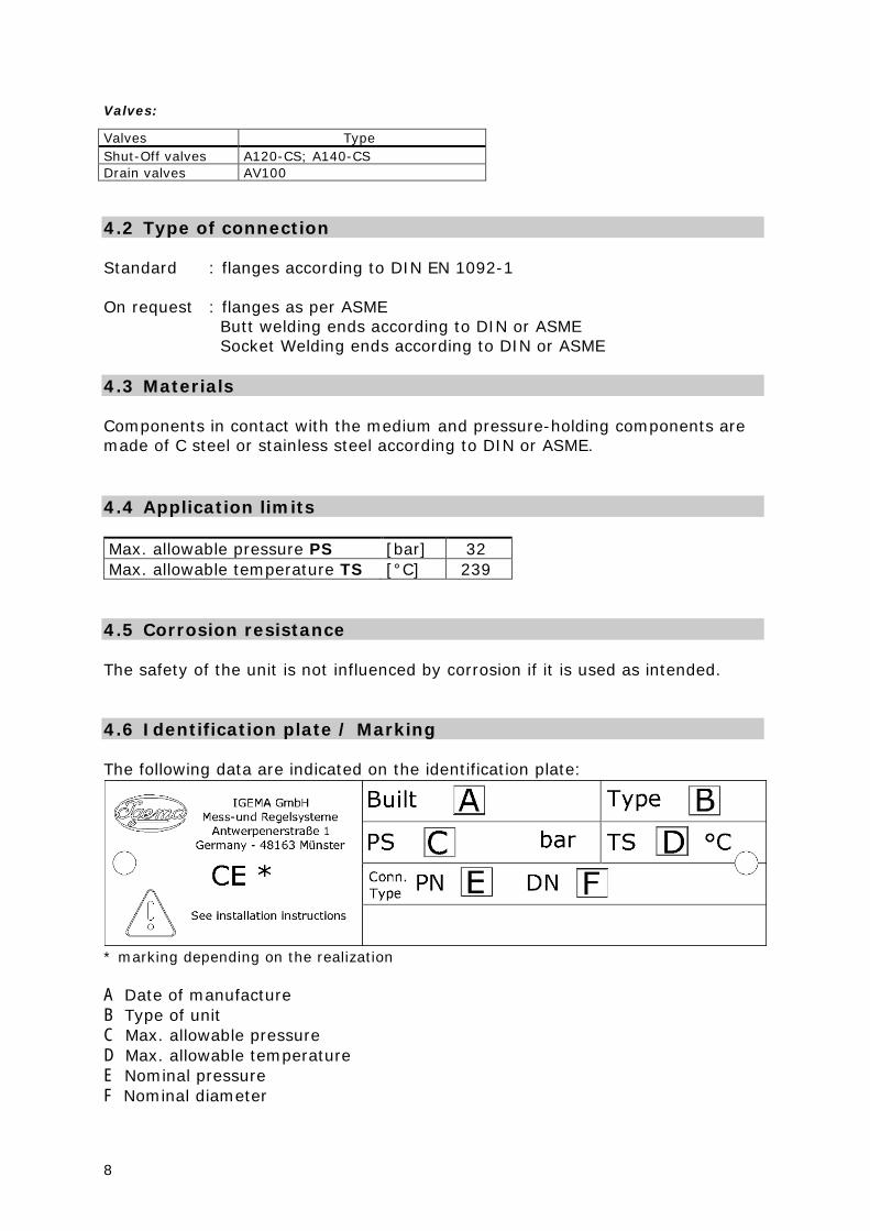
Valves Type Shut-Off valves A120-CS; A140-CS Drain valves AV100 4.2 Type of connection Standard : flanges according to DIN EN 1092-1 On request : flanges as per ASME Butt welding ends according to DIN or ASME Socket Welding ends according to DIN or ASME 4.3 Materials Components in contact with the medium and pressure-holding components are made of C steel or stainless steel according to DIN or ASME. 4.4 Application limits Max. allowable pressure PS [bar] 32 Max. allowable temperature TS [°C] 239 4.5 Corrosion resistance The safety of the unit is not influenced by corrosion if it is used as intended. 4.6 Identification plate / Marking The following data are indicated on the identification plate:
* marking depending on the realization A Date of manufacture B Type of unit C Max. allowable pressure D Max. allowable temperature E Nominal pressure F Nominal diameter
8

5. Construction for example: one sight design
(1) Glass holder (7) Screw holder (2) Upper shutoff valve (8) Locking (3) Lower shutoff valve (9) Sealing (4) Drain valve (10) Glass (5) Plug (11) Sealing (6) Pressure screw (12) Pressure plate
6. Assembly 6.1 Version with flange • Respect installation position! • Remove protecting caps from connection flanges. Caps only serve as
transport protection. • Ensure that sealing surfaces are clean and undamaged. • Mount reflex level gauge. 6.2 Version with butt welding end • Respect installation position!
9
• Remove protecting caps from connection flanges. Caps only serve as transport protection.
• Assembly only by using welding process 111 and 141.
6.3 Heat treatment of weld seams Supplementary temper tests of weld seams are not required! 6.4 Drain piping • Close valves (D1, D2, W1, W2) after mounting. • Mount drain piping on drain valve (4) (to be provided by the customer).
Ensure that drain piping has free outlet to atmosphere and is protected from pressure peaks!
7. Commissioning 7.1 Commissioning of unit together with the boiler Check specifications of material, pressure and temperature! • Close drain valve / plug. • Fully open shutoff devices (D1, D2, W1, W2). 7.2 Commissioning of unit if boiler is already in operating
condition
• Close shutoff device (D2, W2). • Fully open shutoff device (D1,W1) (if exists)and drain valve (4). • Slightly open upper shutoff device (D2), carefully heat up glass holder with
steam until operating temperature is reached. • Closed drain valve. • Slowly open upper shutoff device (D2) and lower shutoff device (W2) as far
as it will go. Wait for alignment of water level. (If water level is not visible, see special operating instructions shutoff valves / drain valve)
(If water level is not visible, see 9.1 General information and operating instructions “self-closing ball”)
7.3 Re-tightening of screws All screw connections except pressure screws
• Before commissioning of level gauge, check all screw connections: plugs, valve and flange connections and screw caps of shutoff valves / drain valve (see special operating instructions shutoff valves / drain valve.
• We suggest to observe the level gauge especially during first days after commissioning.
• Re-tighten firmly screw connection where leakage appears. Pressure screws
10
• Pressure screws have been tightened and tested in our factory with the corresponding tightening torques (see table chapter 8.6). Never re-tighten pressure screws during mounting / commissioning.
• Check if level gauge shows any leakages especially during first days after commissioning.
Leakage
• In case of leakage, close upper and lower shutoff valve (2, 3) and slowly open drain valve (4) a little.
• Fully open drain valve if pressure has escaped. • Re-tighten pressure screws from top to bottom in several steps (see table
chapter 8.6) starting in the centre and using successively opposite diagonal tightening up to a tightening torque of Md max = 60 Nm .
8. Maintenance 8.1 Leakage Re-tighten corresponding screw connection in case of leakage See point 7.3 (Re-tightening of screws). If necessary, replace gasket and check sealing surface.
Severe burns and scaldings on the whole body are possible! Replace gaskets only if level gauge is empty and pressureless!
8.2 Cleaning of glasses During first commissioning or re-commissioning, oil or grease residues can deposit on the inside of the glass. In this case: • Close shutoff valves (2,3). After removing plug (6), the glasses and channel of the gauge body can be cleaned with a circular brush. 8.3 Cleaning / purging of level gauge • Close upper and bottom shutoff devices (D1,D2,W1,W2). • Open drain valve (4), hence unit is drained. Normally, the cleaning is finished
now. • For commissioning see point 7. If cleaning was not sufficient:
• Close upper and bottom shutoff device (D2,W2).
11

• Open upper and bottom shutoff device (D1,W1) (if exists) and drain valve (4). Following that, slowly open upper shutoff device (D2) and steam flowing through the unit cleans the glasses.
• Close upper shutoff device (D2) and drain valve (4) again. • For commissioning see point 7. If this cleaning was not sufficient, replace glass. 8.4 Exchange of glass Always place new glass, new gasket and new cushion! • Close shutoff devices (D1,D2,W1,W2). • Open drain valve (4), hence unit is drained. • Unfasten pressure screws (7) and remove. • Remove upper clamping (9). • Remove right clamping ring (10), pressure plate (14), cushion (13), glass
(12), gasket (11) and screw holder (8). • Remove completely remaining gasket and cushion parts. • Clean sealing surface of gauge body as well as contact surface of pressure
plate. 8.5 Assembly: • Insert sealing (11), glass (12), cushion (13) and pressure plate (14).
Install glass with grooves turned to the medium! • Grease pressure screws (7) with suitable lubricant, screw into screw holder
(8) and insert. • Insert clamping ring (10). • Install clamping (9). • Tighten pressure screws loosely and then in several steps according to the
table (see point 8.6) starting in the centre using successively opposite diagonal tightening up to a tightening torque Md max = 60 Nm.
• For re-commissioning see point 7. 8.6 Tightening torques
Max. Pressure
PS
Tightening torque Md → Md max [Nm]
steps 1 2 3
32 30 45 60
12

9. Shutoff valves Characteristics:
A 1 20 Drain valve Quantity of shutoff possibilities Serial no.
9.1 General information and operating instructions IGEMA valves are mostly maintenance-free and allow an easy handling. All IGEMA valves seal metallically and are hand-operated. Sealing of valve spindle is made with a gland packing. Turn handlever/handwheel clockwisely to close the valve. Turn handlever/handwheel counterclockwisely to open the valve. Tools to increase the hand torque are not allowed. The shutoff valve is equipped with self-closing ball (standard). The self-closing ball is a safety device which automatically closes the valve passage of the shutoff valves on the process side if level gauge is damaged accidentally (glass break). Residuals in piping or fitting (dirt, welding beads etc.) inevitably lead to leakages (seat/cone).
Fig.1 Fig.2 Fig. 3
Ball position during commissioning or flushing/purging
Ball position during normal operation
Ball position during glass/mica break or incorrect commissioning
Functioning of self-closing ball is only guaranteed if valve is fully opened. Residuals (dirt, welding beads etc.) can set self-closing ball out of service.
13

9.2 Construction A120-CS and A140-CS
• Lateral connection M12x48 • Always equipped with handlever • On request: with quick closing spindle
(1) Valve Housing (9) Sealing ring (2) Seat (10,10a) Upper part valve (3) Cone set with stud (12) Ball (4, 4a) Valve spindle, quick closing (15) Hand lever (5) Base ring (16) Sealing ring (6) Gland packing (17) Retaining spring (7) Stuffing box (8) Screw cap
9.3 Commissioning
Before every commissioning, re-commissioning, repair or conversion, ensure proper completion of all installation/assembly works and that valve has correct functioning position. Check specifications of material, pressure and temperature!
• Slightly open shutoff valves with self-closing ball on boiler nozzles containing steam and water counterclockwisely for approximately 5 minutes to prevent that ball closes valve passage (see fig. 1). Fully open spindle after accomplished pressure balance (backseat).
• Compare function of level gauge and water level height with the other safety fittings.
14
9.4 Maintenance
Carry out maintenance works and disassembly only if boiler and level gauge are empty and pressureless.
Observe that lubricant is suitable for medium and operating temperature. Keep spindle thread always greased.
Leakages on spindle (4,4a,14)/gland packing (6)
• Re-tighten screw cap (8). Life of valve can be increased by regular control on tightness.
Replacement of seat (2), cone set (3,13) and ball (12)
• Screw out upper part of valve (10,10a) with valve spindle (4,4a,14) and remove valve housing (1).
• Unfasten screw cap (8) and remove valve spindle (4,4a,14) from valve housing (1) / upper part of valve (10,10a).
• Remove and replace cone set (3,13). • Screw out seat (2) with socket wrench . • Remove ball (12), check and replace if necessary. • Grease thread of new seat (2) and screw in. A120,A210 70 Nm • For assembly see chapter 9.5. Replacement of packing set [Base ring (5), gland packing (6), stuffing box (7)]
• Screw out upper part of valve (10, 10a) with valve spindle (4, 4a, 14) and remove from valve housing (1).
• Unfasten handwheel (11) / handlever (15). • Unfasten screw cap (8) and screw out valve spindle (4, 4a, 14) from valve
housing (1, 1a) / upper part of valve (10, 10a). • Remove packing set (5, 6, 7). • Carefully remove deposits on valve spindle (4, 4a, 14). • For assembly see chapter 9.5. 9.5 Assembly 1. Grease thread of valve spindle (4,4a,14) and screw in valve spindle in valve
housing (1) / upper part of valve (10,10a). 2. Insert base ring (5), gland packing (6) and stuffing box (7). 3. Screw on screw cap (8) and tighten gradually. - spindle has to stay movable - 4. Screw in complete upper part of valve (10, 10a) with new sealing ring (9)
into valve housing (1) with tightening torque Md max = 280 Nm (This step is not applicable for the valve A110) 5. Fix handwheel (11) / handlever (15). 6. Close shutoff device.
15

10. Drain valve 10.1 Construction AV100
• Male thread G½ on input side • Output side with cutting ring connection ø12 as per DIN 2353 – DS12
(1) Valve housing (7) Screw cap (2) Sealing ring (8) Sealing ring (3) Seat (9) Upper part of valve (4) Valve spindle with cone (10) Handwheel (5) Stuffing box (11) Cap nut (6) Gland packing (12) Cutting ring connection 10.2 Assembly
Ensure that drain piping has free outlet to atmosphere and is protected from pressure peaks.
• Firmly screw on drain valve with sealing ring (2) on existing unit. • Assemble drain piping (tube ø 12x1, material St 35.8) on provided pipe union
(14) as per DIN 2353 (on the part of the builder). 10.3 Commissioning
Rust, sand or similar impurities inside of the medium or during first flushing can cause leakage if they remain in the area of the seat. Purging of valve: • Fully open valve for purging. The pre-pressed gland packing can lose its
denseness due to a longer storage (see chapter 10.4). • close valve
16
10.4 Maintenance
Before carrying out maintenance works on drain valve, unit has to be pressureless and empty! Severe burns and scaldings on the whole body are possible!
Re-tightening of gland packing:
• If a valve is leaky, tighten screw cap (8) with open-end wrench (SW27) clockwisely until valve is tight. Spindle (4) has to stay movable.
• Replace gland packing if re-tightening of packing was not successful. Replacement of packing:
• Screw off cap nut (13) and remove handwheel (11). • Unscrew upper part of valve (10). • Remove screw cap (8) and stuffing box (7). • Remove spindle with cone (4) upwards. • Push out gland packing (6) with scraper rings (5) from top and clean packing
space. Assembly:
• Grease spindle thread, insert from top and firmly tighten screws. • Place new greased packing with scraper rings (5). • Insert stuffing box (7). • Tighten screw cap (8). • Insert new sealing ring (9). • Grease thread of upper part of valve (10), screw in and tighten with
tightening torque Md = 220 Nm. • Place handwheel (11) and tighten cap nut (13). Replacement of complete upper part:
• For dismounting of component parts see “Replacement of packing”. • Unscrew seat (3) with hexagon socket wrench SW11. • Grease seat thread, screw in and tighten with tightening torque Md = 55 Nm. • Replace complete upper part. • Insert new spindle. • For assembly of component parts see above.
17

11. Case of damage
Provide security in the danger zone! Severe burns and scaldings on the whole body are possible!
• Check if no further steam escapes at the damaged place. • Set boiler pressureless ! Close valves as follows:
• Close valves on steam and water holding stud. Close shutoff device of main unit at the A210.
• Slowly open drain valve. Level gauge becomes pressureless and water is drained.
• For commissioning with new spare parts see chapter 9.3. 12. Spare parts Always indicate article no. and serial no. (Indicated on the identification plate) in case of spare parts order! 12.1 Reflex level gauge
Pos-N. Designation Size Article-N. Qua.
1 Plug G 1/2" - 40-00329 1
2 Sealing ring ø21 x ø26 x
1,5 mm - 40-00099 1
3 Pressure plate 2 40-00422 nx1
3 Pressure plate 3 40-00423 nx1
3 Pressure plate 4 40-00424 nx1
3 Pressure plate 5 40-00425 nx1
3 Pressure plate 6 40-00426 nx1
3 Pressure plate 7 40-00427 nx1
3 Pressure plate 8 40-00428 nx1
3 Pressure plate 9 40-00429 nx1
3 Pressure plate 10 40-00430 nx1
4-5 Spare part package 2 15-13051 nx1
4-5 Spare part package 3 15-13058 nx1
4-5 Spare part package 4 15-13059 nx1
4-5 Spare part package 5 15-13060 nx1
4-5 Spare part package 6 15-13061 nx1
4-5 Spare part package 7 15-13062 nx1
4-5 Spare part package 8 15-13063 nx1
4-5 Spare part package 9 15-13064 nx1
4-5 Spare part package 10 15-13065 nx1
Spare part package consist of 2x seals and 1x glas
n = number of sight openings
18

12.2 Shut off Valve
12.3 Drain valve
Pos-N. Designation Article-N. Qua. 1 Cone set, seat, ball 15-00116 1 2 Packaging unit 15-00113 1 3 Sealing ring ø9 x ø17,5 x 1,5 mm 40-00109 1 4 Sealing ring ø22 x ø27,5 x 1,5mm 40-00117 1 5 Spindle 25-00126 1 6 Hand lever set 25-00102 1
Pos-N. Designation Article-N. Qua.
1 Spindle with conus 40-11308 1 2 Packaging unit 40-11309 1 3 Sealing ring ø20 x ø24 x 1,5 mm 40-01873 1 4 Sealing ring ø21 x ø26 x 1,5 mm 40-00099 1 5 Hand lever made of sheet steel - 1
19
13. Decommissioning
Severe burns and scaldings on the whole body are possible!
Before detaching flange connections, screws of stuffing box, pressure screws or screw plugs, all connected lines must be pressureless (0 bar) and cooled off to ambient temperature (20°C)!
13.1 Disposal Dismount unit and separate waste products. When disposing the unit, observe legal regulations for waste disposal. 14. Supplement Warranty We accord a warranty period of 24 months on our products. A condition for that is the appropriate treatment according to these mounting and operating instructions. The warranty for wear and spare parts is restricted to material defects and construction faults. The reflex glasses and sealings installed in the reflex level gauge are wear parts and are not included in the warranty. The sealings / gland packing installed in the valves are not included in the warranty.
20

IGEMA GmbH Antwerpener Str. 1
D-48163 Germany
Fon.: +49 25 01 9 24 24 0 Fax.: +49 25 01 9 24 24 99
[email protected] www.igema.com
This high-quality IGEMA product was designed, manufactured and tested with the application of the QM System guidelines in accordance with DIN EN ISO 9001:2000. If the device supplied indicates transport damage or gives cause for complaint in spite of our final quality control please contact our SERVICE department on telephone 0241- 5687-0 by return.
21