reflection and shading - unt computer sciencerenka/4230/reflectionandshading.pdf · shadows;...
TRANSCRIPT

Reflection and Shading
R. J. Renka
Department of Computer Science & EngineeringUniversity of North Texas
10/19/2015
R. J. Renka Reflection and Shading

Light Sources
Realistic rendering requires that we model the interaction betweenlight and objects — reflection from one surface to another;shadows; texture, color, and highlights (bright spots); andrefraction through nonopaque objects. Light hitting a surface isreflected, absorbed, or transmitted through the surface. Thesurface is visible only if it reflects light. Incoming light iscategorized into two types.
Point light comes from a light emitting source (either a pointsource or a distributed source).
Ambient light or background light comes from lightreflecting sources in the scene and outside the scene.
The key distinction is that a point light source has a directionassociated with it, while ambient light comes from all directions.
R. J. Renka Reflection and Shading
Types of Reflection
The physics of reflection is complex, but simple models aresufficient for computer graphics. There are two types of reflection.
diffuse reflection is reflection from a rough surface in alldirections.
specular reflection is reflection from a smooth surface in adirection that depends on the direction to the source.
Phong’s model of reflection includes terms for diffuse reflection ofboth ambient light and point light, and specular reflection of pointlight.
R. J. Renka Reflection and Shading

Diffuse Reflection of Ambient Light
Light hitting a rough surface is scattered in all directions,producing uniform illumination at any viewing position. Theamount of light reflected (not absorbed) depends on the light colorand the surface. Let (Ir , Ig , Ib) denote RGB intensities (normalizedto [0,1]) of reflected light, and let (Iar , Iag , Iab) be the intensities ofan ambient light source. Then the contribution from ambient lightto the total illumination at a surface point is
Ij = kdj · Iaj for j ∈ {r , g , b},
where kdj ∈ [0, 1] is the diffuse reflectivity for the j th primary —the fraction of incoming light that is reflected. The reflectivitiesdefine the color of the surface. A red surface, for example, haskdg = kdb = 0 because green and blue wavelengths are absorbed.Other terms for kdj include diffuse reflectance, diffuse reflectioncoefficient, and diffuse reflection constant.
R. J. Renka Reflection and Shading

Diffuse Reflection of Point Light
Point light hits a surface point with an angle of incidenceφ ∈ [0, π/2]: the angle between the surface normal N and a vectorL that points to the light source. The direction of diffuse reflectionis independent of φ, but the density (and hence intensity) of thepoint light hitting the surface is proportional to cos(φ) = LT N,assuming L and N are unit vectors. This is Lambert’s Cosine Law.Also, intensity of light from a point source decreases with squareddistance d2, but Phong found that replacing d2 with d worksbetter. For point light intensities (Ipr , Ipg , Ipb), the model for thecontribution to overall illumination is
Ij = Ipj · cos(φ) · kdj/d for j ∈ {r , g , b}.
The distance d to the light source is usually taken to be 1 if it islarge relative to the illuminated surface area, implying a negligibledifference at different surface points. Note, however, that if twosurfaces of the same color are parallel and overlap in the projectionplane, they will be indistinguishable unless d varies.
R. J. Renka Reflection and Shading

Specular Reflection of Point Light
Specular reflectivity of a surface is its capacity to reflect incominglight in a nearly fixed direction without changing its color.Specular reflection produces highlights on shiny surfaces such asmirrors. The direction R of reflection is in the plane of L and N,and the angle of reflection is equal to the angle of incidence.
The shininess of the surface determines the concentration of thereflected light around the reflection direction R, and hence the sizeof highlights. The intensity of the incoming light is scaled bycosn(θ), where θ ∈ [0, π/2] is the deviation from R. For any fixedθ ∈ (0, π/2), cosn(θ) decreases, and the reflected light becomesmore concentrated around R, as shininess n increases. Valuesrange from n = 1 for dull surfaces like cardboard to n = 150 ormore for very shiny surfaces like polished silver, with n =∞ for aperfect mirror.
For viewing direction V, θ is the angle between R and V. The lightsource is visible if and only if θ is small or n is small. Note that Vis generally not in the plane of L and N.
R. J. Renka Reflection and Shading

Specular Reflection of Point Light continued
Phong’s model for specular reflection of point light is
Ij = Ipj · ksj · cosn(θ) for j ∈ {r , g , b},
where ksj is a constant that approximates specular reflectance — afunction that depends on the wavelength and angle of incidence φ.The ratio of specularly reflected light to incident light increaseswith φ because the amount of light absorbed, reflected diffusively,or transmitted decreases with φ (is larger at smaller angles ofincidence). A sheet of glass, for example, transmits light hitting itat low incidence angle (face-on), but reflects light at highincidence angle. For materials like glass whose reflectance changessignificantly with φ, ksj should be replaced by a function of φ. Thethree ksj values should be nearly identical so that the reflectedlight has the color of the point light source.
R. J. Renka Reflection and Shading

Phong’s Illumination Model
Combining the above expressions, we have the following reflectionmodel.
Ir = Iar · kdr + Ipr (kdr · cos(φ)/d + ksr · cosn(θ))
Ig = Iag · kdg + Ipg (kdg · cos(φ)/d + ksg · cosn(θ))
Ib = Iab · kdb + Ipb(kdb · cos(φ)/d + ksb · cosn(θ))
Note the following.
All intensity values, as well as reflectances, are in [0,1].
There is only one set of ambient light intensities Iaj , but eachpoint light source contributes terms associated with Ipj .
Parameter values must be determined experimentally.
Specular reflection of ambient light is not included in themodel. The effect of reflecting ambient light in all directionswithout changing its color would be to give the object some ofthe color of the ambient light.
R. J. Renka Reflection and Shading

Surface Normals
Angles φ and θ depend on the surface normal direction N. Theunit normal to a triangle with vertices v1, v2, and v3 is computedby normalizing a cross product:
N = (v2 − v1)× (v3 − v1)/‖(v2 − v1)× (v3 − v1)‖.Smooth shading of a triangle mesh surface requires surfacenormals at vertices. We define the vertex surface normal as anormalized weighted average of the unit normals to the trianglesthat share the vertex. There are various weighting schemes thatdepend on the triangle sizes and shapes. The simple method ofweighting all triangles equally is usually good enough.
In the case of a smooth (regular) parametric surfaceS(u, v) = (x(u, v), y(u, v), z(u, v)), the first partial derivativesSu(u, v) = (xu(u, v), yu(u, v), zu(u, v)) andSv (u, v) = (xv (u, v), yv (u, v), zv (u, v)) are tangent to the surface,and their cross product Su × Sv (nonzero by assumption) is normalto the surface.
R. J. Renka Reflection and Shading

Transparency and Refraction
Refraction is the deflection from a straight path undergone by alight ray in passing obliquely from one transparent medium intoanother in which its velocity is different.
Snell’s Law of Refraction:
n sinφ = n′ sinφ′,
where n and n′ are indices of refraction, and φ, φ′ are angles ofincidence. If 0 < φ < π/2 and n′ > n then sinφ′ = (n/n′) sinφ< sinφ and hence φ′ < φ; i.e., the light ray is bent toward thenormal in passing from one medium, say air, into a medium with alarger index of refraction — a denser material, such as glass orwater.
To render a scene involving refraction, the shift in direction of lightrays must be accounted for. In addition to bending light, atransparent object weakens its intensity and changes its color; e.g.,tinted sunglasses.
R. J. Renka Reflection and Shading

Shading Methods
A polygonal surface can be made to appear smooth by means ofsmooth shading. There are three shading methods.
Lambert Shading (or faceted shading or flat shading)consists of rendering each polygonal face with a single set ofRGB intensities. This makes sense when both the viewer andlight source are far from the surface, and the polygonalsurface is not an approximation to a curved surface.
Gouraud Shading consists of applying an illumination modelonly at the vertices, and computing colors for pixels notassociated with vertices by linear interpolation of the vertexvalues.
Phong Shading consists of applying the illumination modelat every surface point associated with a pixel, but usingnormals obtained by linear interpolation (and renormalization)of the vertex unit normals.
R. J. Renka Reflection and Shading
Shading Methods continued
By using interpolated intensities or normals, the intensities at apoint on an edge depends only on the edge endpoint values. Itfollows that intensities vary continuously across the edge, despitethe discontinuity in the surface normal, thus smoothing out theedge (unless it lies on a boundary not shared by two polygons).Note that polygonal silhouettes are unavoidable.
When lighting is enabled, the OpenGL fixed pipeline uses Gouraudshading by default. Flat shading is more efficient, and should beused if it is acceptable. Note also, that the current drawing color isnot used when lighting is enabled. Providing the option of usingPhong shading is one of the reasons that shading languages havebeen developed as an alternative to the fixed pipeline.
R. J. Renka Reflection and Shading

Shading Methods continued
The tradeoffs between the two smooth shading methods are asfollows.
Gouraud shading is cheaper because there are far fewervertices than pixels, and linear interpolation is much cheaperthan applying the illumination model.
Gouraud shading suffers from poor highlights. Since theillumination model is applied only to vertices, specularreflections only show up for a small range of viewpoints. Also,moving the eye position, object, or light source causes thehighlight to appear and disappear from the vicinity of verticesrather than move smoothly across the surface. Furthermore,interpolation smears out highlights, making them larger thanthey should be. These effects are especially bad for shinysurfaces and with animation. They are mitigated by using alarger number of smaller polygons.
R. J. Renka Reflection and Shading
OpenGL Illumination Model
The illumination model used by OpenGL differs from Phong’smodel as follows.
A light source may be either positional (w 6= 0) or directional(w = 0).
Instead of a single set of ambient light intensities Iaj and pointlight intensities Ipj for each point source, each light source hasambient, diffuse, and specular components. There are alsoglobal ambient light intensities not associated with any of thepoint sources. Realism requires identical diffuse and specularcomponents — the light color. OpenGL also allows alight-emitting material, adding terms to the reflected lightintensities.
A positional point light source can be a spotlight with adirection and an angle defining a cone.
R. J. Renka Reflection and Shading

OpenGL Illumination Model continued
Instead of diffuse reflectivities kdj for both ambient and pointlight, different values may be used. Since they define thematerial color, they should be similar if not identical.
Instead of the attenuation factor 1/d for diffuse reflection ofpoint light, all three components (ambient, diffuse, andspecular) are attenuated by 1/(kc + kl d + kqd2) unless thepoint source is directional.
Note that a light position is transformed to eye coordinates by themodelview matrix only at the time it is specified (by a call toglLightfv). If the light position is to be part of the scene, withposition independent of the viewing perspective, the call toglLightfv must follow any change to the viewing transformations.If, on the other hand, a point light source is positioned at theorigin with the modelview matrix set to the identity, it willeffectively move with the eye position like a miner’s helmet light.
R. J. Renka Reflection and Shading

Vertex Normal Vectors
Lighting calculations require unit normal vectors at the vertices,and they must be transformed from object coordinates to eyecoordinates in a manner that is consistent with vertextransformations by the modelview matrix. Suppose p and q arearbitrary vertices, n is a normal vector, and the modelviewtransformation is defined by Mp = Ap + t. In order to preserve theangle between p− q and n it is necessary to preserve nT (p− q).The solution is to transform n to A−T n. Then
(A−T n)T (Mp−Mq) = nT A−1A(p− q) = nT (p− q).
If A is a rotation, then the norm of n is preserved, but if A involvesscaling, then n must be renormalized, either byglEnable(GL NORMALIZE) or by glEnable(GL RESCALE NORMAL)for uniform scaling by a constant derived from M, which is cheaper.
R. J. Renka Reflection and Shading
Global Illumination
Global illumination models compute reflected light intensities at asurface point by taking into account all light sources, both directand indirect, thus allowing for shadows, reflection of one object inanother, and transparency/refraction. These methods arecomputationally intensive, and are not supported by the fixedOpenGL pipeline. There are two basic approaches.
Ray Tracing treats only specular reflection and isview-dependent, hence too expensive for animation in realtime.
Radiosity treats only diffuse reflection and isview-independent. It is better for softly lit scenes with nosharp shadow boundaries and no shiny surfaces.
R. J. Renka Reflection and Shading

Ray Tracing
Ray tracing in its simplest form works as follows. For each pixel inthe viewport, cast a ray from the eye position through the point(in eye coordinates) that maps to the pixel center. Intersect theray with all objects in the scene to find the point closest to the eyeposition, and apply the illumination model at that point. Thisreplaces the z-buffer algorithm.
Shadow feelersCast a ray from a surface point to a point light source to determineif the light source is visible or occluded by intervening objects.
Reflection RaysWhen a ray hits a surface point, reflect it in the direction ofperfect specular reflection, and then treat it the same way as a rayfrom the eye position — find the first surface intersection point,and calculate that point’s illumination from all light sources.Continue this process recursively.
R. J. Renka Reflection and Shading
Ray Tracing continued
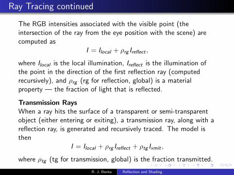
The RGB intensities associated with the visible point (theintersection of the ray from the eye position with the scene) arecomputed as
I = Ilocal + ρrg Ireflect ,
where Ilocal is the local illumination, Ireflect is the illumination ofthe point in the direction of the first reflection ray (computedrecursively), and ρrg (rg for reflection, global) is a materialproperty — the fraction of light that is reflected.
Transmission RaysWhen a ray hits the surface of a transparent or semi-transparentobject (either entering or exiting), a transmission ray, along with areflection ray, is generated and recursively traced. The model isthen
I = Ilocal + ρrg Ireflect + ρtg Ixmit ,
where ρtg (tg for transmission, global) is the fraction transmitted.
R. J. Renka Reflection and Shading

Radiosity
Radiosity consists of four steps.1 Mesh the scene with flat polygonal patches, each with its own
intensities. Some patches are emissive (light sources). Sincepatches are assumed to be uniformly illuminated, they shouldbe smaller in corners where diffuse reflection intensitieschange discontinuously with the normal direction. Time andmemory requirements are O(n2) for n patches.
2 Compute form factors Fij : the fraction of light from patch Pi
that hits patch Pj directly. Fii = 0 and (assuming visibility)
Fij =1
Ai
∫Ai
∫Aj
cosφi cosφj
πr 2
for i 6= j , where Ai is the area of patch Pi , and φi is the anglebetween the normal to Pi and the line segment of length rconnecting a point of Pi to a point of Pj . This is the O(n2)algorithm. The cost can be halved by reciprocity: Fij Ai =Fji Aj . A simple quadrature rule is often sufficient.
R. J. Renka Reflection and Shading
Radiosity continued
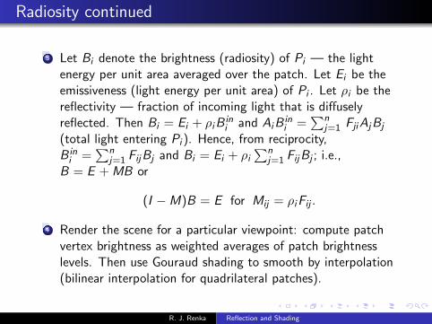
3 Let Bi denote the brightness (radiosity) of Pi — the lightenergy per unit area averaged over the patch. Let Ei be theemissiveness (light energy per unit area) of Pi . Let ρi be thereflectivity — fraction of incoming light that is diffuselyreflected. Then Bi = Ei + ρi B
ini and Ai B
ini =
∑nj=1 Fji Aj Bj
(total light entering Pi ). Hence, from reciprocity,B in
i =∑n
j=1 Fij Bj and Bi = Ei + ρi∑n
j=1 Fij Bj ; i.e.,B = E + MB or
(I −M)B = E for Mij = ρi Fij .
4 Render the scene for a particular viewpoint: compute patchvertex brightness as weighted averages of patch brightnesslevels. Then use Gouraud shading to smooth by interpolation(bilinear interpolation for quadrilateral patches).
R. J. Renka Reflection and Shading