recycled waste foundry sand as a sustainable subgrade fill
TRANSCRIPT
Recycled waste foundry sand as a sustainable subgrade fill and pipe-bedding construction material: engineering and environmental evaluation
This is the Accepted version of the following publication
Arulrajah, A, Yaghoubi, Ehsan, Imteaz, M and Horpibulsuk, S (2017) Recycled waste foundry sand as a sustainable subgrade fill and pipe-bedding construction material: engineering and environmental evaluation. Sustainable Cities and Society, 28. pp. 343-349. ISSN 2210-6707
The publisher’s official version can be found at https://www.sciencedirect.com/science/article/pii/S2210670716305121Note that access to this version may require subscription.
Downloaded from VU Research Repository https://vuir.vu.edu.au/38217/

1
Recycled waste foundry sand as a sustainable subgrade fill and pipe-1
bedding construction material: engineering and environmental evaluation 2
3
1, a Arul Arulrajah 4 Professor, Department of Civil and Construction Engineering, Swinburne University of 5 Technology, Hawthorn, VIC3122, Australia. 6 7 8 2 Ehsan Yaghoubi 9 PhD candidate, Department of Civil and Construction Engineering, Swinburne University of 10
Technology, Hawthorn, VIC3122, Australia. 11 12 13 3 Monzur Imteaz 14
Associate Professor, Department of Civil and Construction Engineering Swinburne University 15 of Technology, Hawthorn, VIC3122, Australia. 16
17 18 4, b Suksun Horpibulsuk 19
Professor and Chair, School of Civil Engineering, and Director, Center of Innovation in 20 Sustainable Infrastructure Development, Suranaree University of Technology, Nakhon 21
Ratchasima 30000, Thailand & 22 Adjunct Professor, Department of Civil and Construction Engineering Swinburne University 23
of Technology, Hawthorn, VIC3122, Australia 24 25
26 27 28
Corresponding Authors: 29 30 a Prof. Arul Arulrajah 31
Department of Civil and Construction Engineering, 32 Swinburne University of Technology, 33 PO Box 218, Hawthorn, VIC 3122, Australia. 34 Tel.: +61 3 92145741; 35 Fax: +61 3 92148264. 36
Email: [email protected] 37
38
39 b Prof. Suksun Horpibulsuk, 40
Address: School of Civil Engineering, Suranaree University of Technology, 111 University 41 Avenue, Muang District, Nakhon Ratchasima 30000, Thailand. 42 Tel.: +66 44 22 4322; fax: +66 44 22 4607. 43 Email: addresses: [email protected] 44 45

2
ABSTRACT 46
Waste foundry sand (WFS) is the primary by-product of foundries. Due to metals present in 47
WFS and negative public perception, this material is commonly discarded to landfill as a waste 48
material. WFS can however be potentially reused as a construction material in civil engineering 49
infrastructure projects. In order to use WFS in a sustainable manner, the engineering properties 50
of this material needs to be properly evaluated and assessed against local requirements. In this 51
research, geotechnical and environmental tests were undertaken to evaluate the properties and 52
viability of WFS for usage in civil engineering construction projects. In addition, control tests 53
were undertaken on recycled glass (RG), a well-accepted waste material that has been 54
successfully implemented in civil engineering applications, for benchmarking purposes. 55
Geotechnical test results, including determination of maximum dry density (MDD) and 56
optimum moisture content (OMC), California bearing ratio (CBR) and permeability, indicate 57
that WFS can satisfactorily be used as fill material in embankments and in pipe-bedding 58
applications. Comparisons of the environmental test results such as chemical composition and 59
leachate analysis, with the requirements of local authorities indicated no particular hazards in 60
the implementation of this material in applications such as road embankment fills and pipe-61
bedding. The carbon footprint savings through any potential reuse of WFS/RG was furthermore 62
quantified. 63
64
65
Keywords: Foundry sand; Environmental; Embankment; Subgrade; Pipe-bedding. 66
67

3
Abbreviations 68
ASLP Australian standard leaching procedure 69
CBR California bearing ratio 70
Cc Coefficient of curvature 71
Cu Coefficient of uniformity 72
Dmax maximum particle size 73
Gs Specific gravity 74
MDD Maximum dry density 75
OMC Optimum moisture content 76
RG Recycled glass 77
WFS Waste foundry sand 78
79
1 Introduction 80
Casting and molding of ferrous and non-ferrous materials is undertaken at foundries 81
(Salokhe and Desai, 2011). This requires specific sized high quality silica sand in order to 82
manufacture molds used for pouring and casting molten metal. Combined application of 83
binders and the silica sand provides a precise shape to molds (Lin et al., 2012). Typical 84
binders used for this action include natural binders (such as bentonite clay) and chemical 85
binders which are used for high temperature operations (Siddique and Singh, 2011). Once 86
the desired shape is precisely generated in the mold, the molten metal is poured in. Repeated 87
utilization of high quality silica sand for casting and molding in foundries results in the 88
production of waste foundry sand (WFS) (Lin et al., 2012). In fact, the sand used to create 89
the required shape in the mold is repeatedly used for the casting process until it is 90

4
thoroughly contaminated, at which point the WFS is discarded, o f t e n t o l a n d f i l l s 91
(FHWA, 2004 and Saloke and Desai, 2011). 92
Waste sands are widely used in geotechnical applications and are divided into several major 93
categories: foundry sands, raw slags, heavy ashes and metal fractions. Among these, WFS is 94
commonly used due to its availability, mineral-rich properties and overall similarities in 95
properties to natural and recycled sands (Saloke and Desai, 2011). Typically, WFS can be 96
categorized into green sand and chemically bonded sand, depending on the type of 97
binder used in casting (Siddique and Singh, 2011). Depending on the color, WFS can be 98
distinguished on the basis of binders. Green sand colors black or grey whereas 99
chemically bonded sand colors medium tan or off white (Siddique and Singh, 2011). As 100
dumping this by-product is often costly, it has recently been used in applications such as hot 101
mix asphalt fillers, cement manufacture (FHWA, 2004), embankments (Mast and Fox, 1998; 102
Partridge et al., 1998) and road subbases (Guney et al., 2006; Goodhue et al., 2001). 103
Countries such as the USA, India, China, Australia and Taiwan generate millions of tons of 104
waste WFS, which poses an enormous environmental challenge (Lin et al., 2012). The 105
sustainable usage of WFS provides an economical and environmentally friendly solution as 106
compared to the high costs of disposing to landfills and for quarrying virgin materials (Siddique 107
and Singh, 2011). Partridge et al. (1999) and Guney et al. (2006) have reported that WFS 108
material is safe to be used in some engineering applications. WFS is hydrophilic by nature and 109
absorbs high amounts of water. Also, due to existence of phenols, this material may be 110
corrosive (Siddique and Singh, 2011). Suitability of application of WFS in regards to 111
environmental issues can be evaluated through leachate analysis. In the landfills for instance, 112
precipitation and percolation of the water through deposited material generates leachate 113
(Siddique et al., 2010). In the majority of past research, WFS was either stabilized using 114
cementitious material (cement, lime, etc.), or used as a substitute to the sand portion of a blend, 115
such as concrete mixture or hot mix asphalt. 116

5
Table 1 presents a summary of results of a few research works, as well as, typical properties 117
presented in FHWA (2004). In this table, values of optimum moisture content (OMC), 118
maximum dry density (MDD), and California bearing ratio (CBR) corresponding to specimens 119
compacted using standard compaction effort are presented. In two of the selected research 120
works, WFS was used solely without being mixed with other materials. In the others, however, 121
it was blended with bentonite (Abichou et al., 2000), mixed with cement (Naik et al., 2001), or 122
used together with geosynthetics (Guney et al., 2006). Generally, just a few research works 123
were encountered in the literature review in which WFS was used as an individual material, 124
instead of being mixed with other materials in a blend. In recent years, recycled materials have 125
been evaluated and deemed acceptable in various civil engineering infrastructure applications 126
(Arulrajah et al., 2014a). Recycled glass (RG) in particular, has made significant inroads in 127
recent years and has been deemed suitable for applications such as embankment fills (Wartman 128
et al. 2004), pavement subbases (Arulrajah et al., 2014b), cement treated pavement base 129
(Arulrajah et al., 2015a), footpath bases (Arulrajah et al., 2013), as well as light-weight fill 130
applications (Arulrajah et al., 2015b). The environmental properties of RG have also been 131
established as being compliant with required regulatory requirements (Imteaz et al., 2012). RG 132
is furthermore sold commercially in Australia and is marketed as a recycled sand product. RG 133
is therefore considered an ideal material for benchmarking the performance of WFS as an 134
engineering fill and pipe-bedding material. Conducting a series of studies on WFS, as with RG, 135
provides the engineers and designers with adequate knowledge on properties of this material 136
and paves the way to extensive reuse of this waste material in civil engineering projects. In this 137
regards, comparing the properties of WFS with an approved recycled material (RG) gives a 138
clearer appreciation of its suitability in similar applications. 139
Even though the majority of the WFS evaluated in the literature meet the environmental 140
requirements, applying a leachate analysis protocol is recommended for each new source of 141

6
WFS that is intended to be used (FHWA, 2004). Furthermore, the majority of the recent 142
research works only focus on the properties of the blends in which WFS is used as a component, 143
rather than properties of WFS by itself. Application of WFS without mixing with other 144
materials, if the requirements are met, can save costs and effort needed for the mix design and 145
blending and mixture preparation. At the same time, it meets the aim of reusing WFS rather 146
than dumping it in landfills. 147
In this research, the environmental and engineering properties of WFS, obtained from a 148
recycling facility in Melbourne, Australia, were evaluated and the suitability of this material as 149
a subgrade fill and pipe-bedding material was reported. Key gaps in recent research on WFS, 150
such as comparisons of its properties with another widely accepted alternative recycled sand 151
product, being RG as an engineering fill and pipe-bedding material were a primary focus of 152
this research. The properties of WFS as benchmarked with RG will answer key remaining 153
questions on the engineering and environmental performance of WFS as compared to other 154
accepted recycled materials in applications such as engineering fill and pipe-bedding, and 155
positive outcomes will lead to wider acceptance of WFS as a construction material. The carbon 156
footprint savings through any potential reuse of WFS/RG was furthermore quantified. 157
158
2 Materials and Methods 159
The WFS and RG used in this research were provided from a recycling construction and 160
demolition facility in Melbourne, Australia. The WFS was black in color, due to the presence 161
of contaminants, during operational works. The RG was a mixed colored glass, which is too 162
fine a material to be color sorted back into bottle-making, and thus enters the waste stream 163

7
(Arulrajah et al., 2014b). Figure 1(a) shows a photo of WFS while Figure 1(b) shows a photo 164
of RG. 165
The particle size distribution of WFS was obtained using ASTM D6913-04 (2009). In addition 166
to the sieves recommended in the standard, 2.36 mm, 1.7 mm and 1.18 mm sieves were used 167
so that a more precise PSD was achieved. Also, 250 g samples were used so that overloading 168
limits for each sieve according to ASTM D6913-04 (2009) was met. Specific gravity (Gs) of 169
the material was obtained using ASTM D854-14 (2014). In this regard, 100 g of dry material 170
was used and method B (Procedure for oven-dry samples) was applied using a 500 mL 171
pycnometer. Deairing was done using a vacuum pump and a shaking table for agitating the 172
slurry while it was under vacuum for two hours. 173
Standard compaction procedure, according to ASTM D698-15 (2015), was carried out to 174
determine the moisture content-dry density relationship of the materials. A 101.6 mm diameter 175
by 116.43 mm high mold was used and the specimens with 5 different moisture contents, 176
ranging between 7 to 14%, were prepared. Each specimen was compacted in 3 layers, under 177
standard compaction effort of 25 blows. 178
California bearing ratio (CBR) tests were conducted in accordance with ASTM D1883-14 179
(2014). A 152 mm diameter by 177.1 mm high mold was used, and WFS and RG were wetted 180
to their corresponding optimum moisture content (OMC) and were compacted in 3 layers using 181
standard compaction effort. In order to investigate the swelling potential of the material 182
(existence of clay), a dial gauge was used while the CBR specimens were submerged in water 183
for 96 hr. The CBR values at 2.54 mm and 5.08 mm penetration were then obtained using 184
stress-penetration curves, with the higher CBR value being reported. In this regard, correction 185

8
for concavity of the stress-penetration curves done following ASTM D1883-14 (2014) 186
procedure. 187
Hydraulic conductivity of the materials was obtained using constant head permeability test 188
according to (ASTM-D2434, 2006) which is applicable for granular materials. Samples were 189
compacted in a 152 mm diameter mold in 3 layers using standard compaction effort. The head 190
difference was 1.14 meter of water column. Permeability of a recycled/reused material is a 191
useful measure for evaluation of its potentials for leaching. 192
An X-ray fluorescence test was conducted to determine the chemical composition of the WFS 193
and RG. The hazard category of WFS was determined based on the Environmental Protection 194
Authority (EPA, 1999 and 2010) Victoria and Australian standard leaching procedure (ASLP) 195
(AS, 1997), which is a bottle leaching procedure. The allowable maximum particle size for this 196
procedure is 2.4 mm, which is greater than Dmax of materials used in this research, hence, no 197
sieving was required. The environmental properties of the WFS were tested for different types 198
of heavy metals by following the Australian standards protocol (AS, 1997) for the preparation 199
of leachate, using neutral water (pH = 7) as leaching fluid. Leachate was produced by 200
contacting the WFS and RG with the leaching fluid. This was done by placing the material in 201
the bottle of the apparatus and adding the leaching fluid. The bottle was then sealed and 202
mounted into an agitator to be shaken for 18 hours. The mix was then filtered using a glass 203
fiber filter and the filtered liquid was used for leachate analysis. If the ASLP leachate 204
concentrations are less than the specified limits, or if it can be demonstrated to be of natural 205
origin, the WFS can be categorized as suitable for fill materials. 206

9
3 Results and Discussion 207
The geotechnical and environmental properties of WFS were compared with those of RG, a 208
well-accepted recycled waste material for benchmarking purposes. Figure 2 presents the 209
particle size distribution of WFS and RG and also reports on other properties including 210
maximum particle size (Dmax), mean particle size (D50), coefficient of uniformity (Cu) and 211
coefficient of curvature (Cc). The particle size distribution curves indicate that the WFS 212
contains about 2% fines, has a Dmax of 2.36 mm, and has a Cc lower than 6. Therefore, it is 213
classified as poorly graded sand while RG is well graded sand. Atterberg limit tests are not 214
applicable for these materials, due to very low percentage of fine particles. In the majority of 215
the research works mentioned in the introduction section, WFS was poorly graded. 216
Figure 3 presents the compaction curve of WFS, as well as the OMC and MDD of WFS and 217
RG. The compaction curve shows that compared to RG, WFS has lower MDD, even though 218
WFS has greater specific gravity value. This is attributed to the fact that the RG blend was 219
well-graded, whereas WFS blend is poorly-graded. Also, greater OMC of WFS suggests that 220
water absorption of this material is higher than that of RG. The MDD of WFS falls in the range 221
of typical foundry sand (without fine particles) available in the literature (Table 1). However, 222
the optimum moisture content of WFS in this research is greater than the upper range of typical 223
WFS with no clay/silt presented in FHWA (2004). This might be due to presence of about 2% 224
clay in the WFS used in this research. Also, OMC as high as 15.5 was reported in Partridge et 225
al. (1999) which is well above that of WFS of this research. 226
No significant reading was observed on the dial gauges after 96 hours of submerging the CBR 227
specimens in water, suggesting that these materials were non-swelling and contained negligible 228
or low percentage of clay. CBR was then conducted on the specimens. Figure 4 presents the 229
stress-penetration curves for WFS and RG. CBR values for WFS were greater than the typically 230

10
specified within the range of 2% to 5%. This is the local road authority specification 231
requirements for a structural fill material in road embankments. Therefore, WFS meets the 232
requirements to be used in road applications, to RG. Evidently, RG achieves greater CBR 233
values than WFS, which can be attributed to its larger particle size, as well as a well-graded 234
particle size distribution. The CBR value of the WFS is close to the lower limit of the typical 235
WFS presented in (FHWA, 2004). However, the minimum CBR value reported in the literature 236
was 4.3 and belongs to Kleven et al. (2000). 237
Hydraulic conductivity of the WFS was 5.20 x 10⁻⁸ m/s, which is highly lower than that of RG 238
(9.79 x 10⁻⁶). Permeability of the WFS used in this research is a bit greater than the lower limit 239
presented in Table 1 for typical WFS without fine particles, but falls between the range 240
presented by Abichou et al. (2000). Generally, permeability of WFS tends to be lower than 241
typical sand and is not therefore considered as a freely draining material (Partridge et al., 1999). 242
This makes it suitable for construction materials where low permeability is required, such as 243
landfill covers, liners, and even earth dam cores (Deng and Tikalsky, 2008). 244
A summary of the geotechnical properties of WFS is presented in Table 2 and compared with 245
those of RG. Generally, RG presents better properties, including higher MDD and CBR value; 246
however, WFS also presents acceptable properties for embankment fill applications. From an 247
engineering material perspective, the properties of the WFS coupled with its satisfactory 248
engineering and environmental results indicate that the material is ideal for usage as a fill 249
material in embankments or retaining, walls as well as a pipe-bedding material. The properties 250
of the WFS used in this research are to a great extent similar to those used in previous research 251
with satisfactory results (Table 1). 252
Table 3 presents the chemical composition of the WFS used in this research obtained from X-253
ray fluorescence (XRF). Total amount of major components in WFS (SiO2, Al2O3, and Fe2O3) 254

11
is 97.50%. Major components of RG include SiO2, CaO, and Al2O3 which constitute 97.69% 255
of the blend. Evidently, both the materials contain large SiO2 content due to their origins from 256
sands. Generally, high amounts of SiO2 in aggregates result in greater hardness (Siriphun et al., 257
2016). 258
A disadvantage in applications with WFS could be the potential of leaching toxic substances 259
Leachate analysis, especially for WFS, is important since it has been exposed to melt metals in 260
high temperatures during the casting process. This could introduce toxic metals into WFS 261
(Guney et al., 2006). The majority of the studies carried out on evaluation of the leachate from 262
WFS show that concentration of hazardous material was lower than the limits provided by the 263
authorities. However, a few research works, such as (Coz et al., 2004), among others, have 264
reported concentration of contaminants in WFS that exceeded the safety limits. This suggests 265
necessity of conducting leachate analysis on any new source of WFS that is intended to be used 266
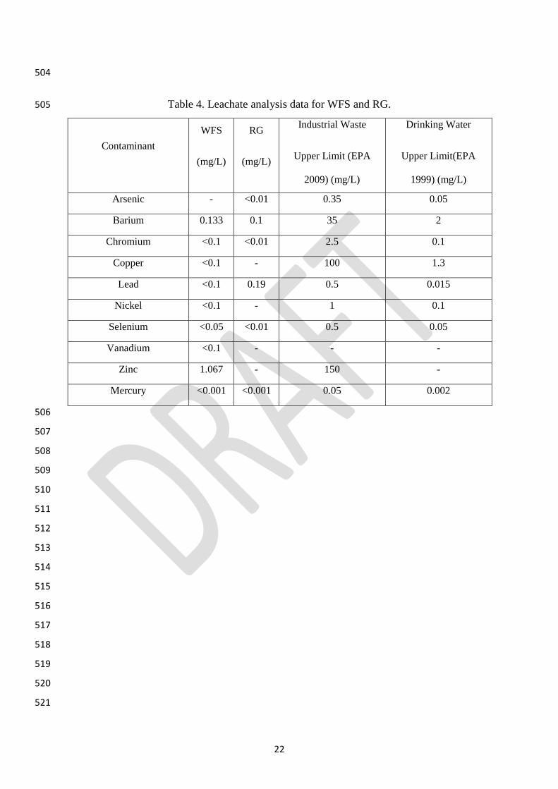
for construction and have potential of leaching. Table 4 presents the leachate analysis data of 267
the WFS and RG and compares it to the requirements for fill material, drinking water and 268
hazardous waste. Based on the U.S. Environmental Protection Agency, a material is considered 269
as hazardous if any metal is present in concentrations greater than 100 times that of the drinking 270
water standards (Wartman et al., 2004). A comparison of the leaching results indicates that all 271
metal contaminants are well within allowable limits for the usage of WFS as a fill material. In 272
RG, however, only for lead, the leachate concentration gets close to threshold defined by EPA 273
Victoria for solid inert waste. But considering that the leachate values, reported in Table 4 for 274
WFS, are extracted using more aggressive acidic and borate solutions compared to neutral pH 275
water, it can be expected that in case of using this material in the field and event of storm water 276
passing through the material, the concentration of heavy metals will be less than what reported 277
in Table 4. This means that the material will not pose any risk to the ground water tables or 278
water streams beyond what is commonly accepted for fill material and solid inert waste. 279

12
Figure 5 presents a schematic and a water flow balance diagram for the usage of WFS fill 280
material in a typical application as a road embankment fill material. Precipitation due to rainfall 281
will hit the pavement surface layer, with some of it subsequently evaporating and the balance 282
becoming run-off that will discharge down the slopes and into the drains provided at the bottom 283
of the road embankment. Some infiltration will occur into the WFS fill material layer. Leachate 284
will seep into the ground water table below; hence, the necessity for the environmental testing 285
analysis undertaken in this research. Based on the above-mentioned leaching and engineering 286
analyses, the WFS is found to be suitable as a non-structural fill material for road 287
embankments. As a structural fill material in road embankments, the particle size distribution 288
of the aggregates meets the requirements of local road authority specifications. 289
Evidently recycled materials will contribute to total energy savings considering the effects of 290
embodied energy. Embodied energy is the total energy that is associated in bringing a material 291
to its existing virgin state (Soga et al., 2011). Embodied energy is closely related to the resource 292
depletion and greenhouse gas emission, as more embodied energy means more greenhouse gas 293
emissions. Moreover, dumping the high embodied energy material contributes high energy 294
depletion/waste. Hence, this parameter reflects the energy-efficiency and environmental effect 295
of a material. 296
Earlier studies revealed that the use of RG as engineering material is able to save total energy 297
related to the material up to 2 orders of magnitude, as compared to virgin aggregate-cement 298
(EPA, 2012; Nassar and Soroushian, 2013; Tsai, 2005). WFS is a recycled waste material and 299
is not intentionally produced for construction. Hence, the embodied energy of WFS is regarded 300
as zero. In contrast, the embodied energy of conventional Portland cement additive is as high 301
as 4.6 MJ/kg (Hammond and Jones, 2008). Ignoring the transportation cost (which will be 302
close/similar to other virgin material), the total energy consumption related to the use of WFS 303
as construction material in practice (e.g., non-structural fill material) is therefore zero, whereas 304

13
that of a conventional aggregate-cement material depends on the cement dosage and weight 305
employed in any construction project. If WFS is used to replace quarry sand resource, then 306
based on the unit data reported by Racusin and McArleton (2012) per ton the use of WFS will 307
save embodied energy of 81 MJ; and will reduce carbon emissions of 4.8 kg CO2 and 5.1 kg 308
CO2 e. 309
4 Recommendations for future research 310
In the present research, WFS was evaluated in terms of environmental and basic geotechnical 311
properties. It met the local authority requirements for environmental safety. However, more 312
advanced geotechnical testing is required to investigate its suitability in a range of other civil 313
engineering applications. Since it is a type of recycled sand, investigating the shear strength 314
properties and compressibility of the WFS is recommended. In addition to that, blending this 315
material with other recycled materials, such as recycled construction and demolition materials 316
with the aim of using a 100% recycled blend is recommended. A field trial on WFS will 317
furthermore provide conclusive evidence of actual performance of this material under actual 318
loading conditions. In regards to environmental assessment, as some contaminants (although 319
below specified limit) are present in the WFS sample, it is recommended to investigate whether 320
concentrations of contaminants can be reduced through some soil treatment, i.e. soil washing. 321
5 Conclusions 322
A series of geotechnical and environmental tests were conducted on WFS and benchmarked 323
against RG to evaluate the engineering properties of WFS and to investigate the viability of 324
using this by-product of foundry industries in road construction. WFS were found to meet the 325
local road authority requirements as a non-structural fill and pipe bedding material. The particle 326
size distribution curves indicate that the WFS was poorly graded and comprised essentially of 327

14
sand sized particles. CBR values for WFS are greater than the typically specified within the 328
range of 2% to 5%, which is the local road authority specification requirements for a structural 329
fill material in road embankments. The WFS contained a large SiO2 content due to its origins 330
from natural sands. Comparing geotechnical testing results of WFS with RG indicates that the 331
properties of WFS are lower than that of RG. However, engineering properties of WFS, such 332
as compaction and CBR values make it acceptable for fill embankment applications. 333
Leachate analysis results were obtained and compared with the requirements of regulatory 334
authorities. Results indicated no environmental risks for using WFS in road applications, such 335
as embankment fill and pipe bedding. Evidently the leachate through this material is not 336
suitable for drinking. Pollutants in the leachate will go through diffusion and dispersion 337
processes before it reaches the ground water source, as such concentrations of any pollutants 338
will be significantly reduced. Such transport of pollutants can be precisely calculated using 339
groundwater flow models, which is out of scope for this research. Moreover, the use of WFS 340
instead of quarry sand will save embodied energy, as well as reducing carbon footprint. 341
Acknowledgements 342
The authors wish to thank Alex Fraser Group (Victoria, Australia) for providing the foundry 343
sand and recycled glass material for this research project. The last author is grateful to the 344
Suranaree University of Technology, the Office of Higher Education Commission under NRU 345
project of Thailand and the Thailand Research Fund under the TRF Senior Research Scholar 346
program Grant No. RTA5980005. 347
Compliance with Ethical Standards: 348
Funding: This study was unfunded. 349
Conflict of Interest: The authors declare that they have no conflict of interest. 350

15
References 351
Abichou, T., Benson, C.H., Edil, T.B., (2000). Foundry green sands as hydraulic barriers: 352 laboratory study. Journal of Geotechnical and Geoenvironmental Engineering 126, 1174-1183. 353
Arulrajah, A., Ali, M.M.Y., Disfani, M.M., Piratheepan, J. and Bo, M.W. (2013). Geotechnical 354
performance of recycled glass-waste rock blends in footpath bases. Journal of Materials in 355 Civil Engineering, ASCE, 25(5), 653–661. 356
Arulrajah, A., Disfani, M., Horpibulsuk, S., Suksiripattanapong, C. and Prongmanee, N. 357 (2014a). Physical properties and shear strength responses of recycled construction and 358 demolition materials in unbound pavement base/subbase applications, Construction & 359
Building Materials, Vol. 58, pp. 245–257. 360
Arulrajah, A., Ali, M.M.Y., Disfani, M.M. and Horpibulsuk, S. (2014b). Recycled glass blends 361
in pavement base/subbase applications: laboratory and field evaluation. Journal of Materials 362 in Civil Engineering, ASCE, 26(7), 04014025(1-12) 363
Arulrajah, A., Disfani, M.M., Haghighi, H., Mohammadinia, A. and Horpibulsuk, S. (2015a). 364 Modulus of rupture evaluation of cement stabilized recycled glass/recycled concrete aggregate 365
blends. Construction & Building Materials, 84, 146-155. 366
Arulrajah, A., Disfani, M.M, Maghoolpilehrood, F., Horpibulsuk, S., Udonchai, A. Imteaz, M. 367
and Du, Y-J. (2015b). Engineering and environmental properties of foamed recycled glass as 368 a lightweight fill material. Journal of Cleaner Production, 94, 369-375. 369
AS, (1997). Wastes, Sediments and Contaminated Soils, Part 3: Preparation of Leachates-370 bottle Leaching Procedure. Australian Standards 4439.3. Standards Australia, Homebush, 371
NSW, Australia. 372
ASTM-D698-15 (2015). Standard Test Methods for Laboratory Compaction Characteristics 373 of Soil Using Standard Effort (12 400 ft-lbf/ft3 (600 kN-m/m3)). West Conshohocken, PA: 374
ASTM International. 375
ASTM-D854-14 (2014). Standard Test Methods for Specific Gravity of Soil Solids by Water 376 Pycnometer. West Conshohocken, PA: ASTM International. 377
ASTM-D1883-14 (2014). Standard Test Method for CBR (California Bearing Ratio) of 378
Laboratory-Compacted Soils. West Conshohocken, PA: ASTM International. 379
ASTM-D2434 (2006). Standard Test Method for Permeability of Granular Soils (Constant 380 Head). ASTM International, West Conshohocken, PA: ASTM International. 381
ASTM-D6913-04 (2009). Standard Test Methods for Particle-Size Distribution (Gradation) of 382 Soils Using Sieve Analysis. West Conshohocken, PA: ASTM International. 383

16
Coz, A., Andrés, A., Soriano, S., Irabien, Á., (2004). Environmental behaviour of stabilised 384
foundry sludge. Journal of Hazardous Materials 109, 95-104. 385
EPA, (1999). National primary drinking water standards, EPA-F-94-001. Environment 386 Protection Agency, Washington, USA. 387
EPA, (2010). Waste Categorization Industrial waste resource guidelines. Environmental 388
Protection Agency of Victoria, Australia, Victoria, Australia. 389
EPA, (2012). Methodology for estimating MSW recycling benefits., Washington DC., USA 390
Deng, A., Tikalsky, P.J., 2008. Geotechnical and leaching properties of flowable fill 391 incorporating waste foundry sand. Waste Management 28, 2161-2170. 392
FHWA (2004). Foundry sand facts for civil engineers. Report No.: FHWA-IF-04-004 prepared 393 by American Foundrymen’s Society Inc. for Federal Highway Administration Environmental 394 Protection Agency Washington, DC, USA, 80 p 395
Goodhue, M.J., Edil, T.B., Benson, C.H., (2001). Interaction of foundry sands with 396
geosynthetics. Journal of Geotechnical and Geoenvironmental Engineering 127, 353-362. 397
Guney, Y., Aydilek, A.H., Demirkan, M.M., (2006). Geoenvironmental behavior of foundry 398 sand amended mixtures for highway subbases. Waste Management, 26, 932-945. 399
Hammond, G.P., Jones, C.I., (2008). Inventory of (embodied) carbon and energy. Department 400 of Mechanical Engineering, 1.6a ed. University of Bath, Bath, United Kingdom. 401
Imteaz, M., Ali, M.M,Y. and Arulrajah, A. (2012). Possible Environmental Impacts of 402 Recycled Glass Used as a Pavement Base Material. Waste Management and Research, 30(9), 403
917-921. 404
Kleven, J., Edil, T., Benson, C., (2000). Evaluation of excess foundry system sands for use as 405 subbase material. Transportation Research Record: Journal of the Transportation Research 406
Board, 40-48. 407
Lin, K.L., Cheng, C.J., Cheng, A., Chao, S.-J., (2012). Study on recycled waste foundry sand 408 as raw materials of cement additives. Sustainable Environment Research 22, 91-97. 409
Mast, D.G., Fox, P.J., (1998). Geotechnical performance of a highway embankment 410
constructed using waste foundry sand. Recycled materials in geotechnical applications. ASCE, 411 pp. 66-85. 412
Naik, T.R., Singh, S.S., Ramme, B.W., (2001). Performance and leaching assessment of 413 flowable slurry. Journal of Environmental Engineering 127, 359-368. 414

17
Nassar, R.U.D., Soroushian, P., (2013). Use of milled waste glass in recycled aggregate 415
concrete. Proceedings of Institution of Civil Engineers: Construction Materials 166, 304-315. 416
Partridge, B., Fox, P., Alleman, J., Mast, D., (1999). Field demonstration of highway 417 embankment construction using waste foundry sand. Transportation Research Record: Journal 418 of the Transportation Research Board, 98-105. 419
Racusin, J.D. and McArleton, A., (2012). The Natural Building Companion, Chelsea Green 420 Publishing, USA, ISBN: 9781603583398. 421
Salokhe, EP & Desai, DB 2011, Application of Foundry Sand In Manufacture of Concrete. 422 Journal of Mechanical and Civil Engineering, ISSN 2278-1684, pp. 43-48. 423
Siddique, R., Kaur, G., Rajor, A., (2010). Waste foundry sand and its leachate characteristics. 424 Resources, Conservation and Recycling 54, 1027-1036. 425
Siddique, R., Singh, G., (2011). Utilization of waste foundry sand (WFS) in concrete 426
manufacturing. Resources, Conservation and Recycling, 55, 885-892. 427
Siriphun, S., Chotisakul, S., Horpibulsuk, S., (2016). Skid Resistance of Asphalt Concrete at 428 the Construction Stage Based on Thai Aggregates. Journal of Materials in Civil Engineering 429 0, 04016145. 430
Soga, K., Chau, C., Nicholson, D., Pantelidou, H., (2011). Embodied energy: Soil retaining 431 geosystems. KSCE Journal of Civil Engineering, 15, 739-749. 432
Tsai, C., Krogmann, U. and Strom, P., (2005). Expanding markets for and preventing 433 stormwater pollution from mixed glass cullet in New Jersey. Rutgers University, New 434
Brunswick, NJ, USA. 435
Wartman, J., Grubb, D.G., Nasim, A.S.M., (2004). Select engineering characteristics of 436 crushed glass. Journal of Materials in Civil Engineering, 16, 526-539. 437
438
439
440

18
LIST OF TABLES 441
Table 1. Summary of the WFS properties presented in the literature 442
Table 2. Engineering properties of WFS and RG. 443
Table 3. Chemical composition of WFS and RG. 444
Table 4. Leachate analysis data for WFS and RG. 445
446
447
448
449
450
451
452
453
454
455
456
457
458
459
460
461
462
463
464
465
466
467
468
469

19
Table 1. Summary of the WFS properties presented in the literature 470
Research
work Gs
Dmax
(mm)
OMC
(%)
MDD
(Mg/m3)
CBR
(%) USCS
Permeability
(m/s)
Safe
Environmentally
Can be used
solely
Partridge et al.
(1999) 2.53 - 15.5 1.43 16.8 - 1.2*10-8 Yes Yes
Kleven et al.
(2000)
2.52-
2.73 4.75
9.6-
13.8
1.69-
1.88 4.3-40
SP/SM
(majority) -
Not
reported Yes
Abichou et al.
(2000)
2.51-
2.62
10.8-
12.3
1.65-
1.86
SM/SC
(majority)
9*10-11-
5.3*10-7
Not
reported No
Naik et al.
(2001) 2.79 2.36 - - - SP - Yes No
Goodhue et al.
(2001)
2.52-
2.68 4.75 9.6-15
1.72-
1.88 -
SP-SM/
SW-SM/
SC
- Yes No
Typical WFS
(with clay/silt)
(FHWA,
2004)
2.5-
2.7
1.18-
4.75 8-12
1.76-
1.84 11-30
SP-SM/
SP-SC 10-9-10-5 Inconclusive Inconclusive
Typical WFS
(without
clay/silt)
(FHWA,
2004)
2.6-
2.8
1.18-
4.75 8-10
1.60-
1.76 11-30 SP 10-8-10-4 Inconclusive Inconclusive
471
472
473
474
475

20
476
477
Table 2. Engineering properties of WFS and RG 478
Engineering Parameter WFS RG
Specific Gravity (Gs) 2.59 2.48
Coefficient of Uniformity (Cu) 2.06 7.5
Coefficient of Curvature (Cc) 0.92 1.5
Standard Proctor OMC (%) 12.5 12.05
Standard Proctor MDD (Mg/m3) 1.748 1.777
CBR (%) 10.9 39
Permeability (m/s) 5.20 x10⁻⁸ 9.79 x 10⁻⁶
479
480
481
482
483
484
485
486
487
488
489
490
491

21
492
Table 3. Chemical composition of WFS and RG 493
Chemical
Composition (%)
WFS RG
Silica (SiO2) 84.145 80.124
Aluminium oxide (Al2O3) 11.817 3.980
Ferric oxide (Fe2O3) 1.533 0.688
Calcium oxide (CaO) 1.507 13.583
Sulfur trioxide (SO3) 0.453 0.436
Potassium oxide (K2O) 0.287 0.561
Titanium dioxide (TiO2) 0.257 0.399
Manganese dioxide (MnO2) - 0.027
Chromia (Cr2O3) - 0.071
Zinc oxide (ZnO) - 0.027
494
495
496
497
498
499
500
501
502
503
22
504
Table 4. Leachate analysis data for WFS and RG. 505
Contaminant
WFS
(mg/L)
RG
(mg/L)
Industrial Waste
Upper Limit (EPA
2009) (mg/L)
Drinking Water
Upper Limit(EPA
1999) (mg/L)
Arsenic - <0.01 0.35 0.05
Barium 0.133 0.1 35 2
Chromium <0.1 <0.01 2.5 0.1
Copper <0.1 - 100 1.3
Lead <0.1 0.19 0.5 0.015
Nickel <0.1 - 1 0.1
Selenium <0.05 <0.01 0.5 0.05
Vanadium <0.1 - - -
Zinc 1.067 - 150 -
Mercury <0.001 <0.001 0.05 0.002
506
507
508
509
510
511
512
513
514
515
516
517
518
519
520
521

23
522
523

24
524
525
LIST OF FIGURES 526
Figure 1. Close up photos of (a) WFS and (b) RG. 527
Figure 2. Gradation curves for WFS and RG. 528
Figure 3. Compaction curves for WFS and RG. 529
Figure 4. CBR results for WFS and RG. 530
Figure 5. Water flow balance chart for WFS as a fill material in road embankments. 531
532
533
534

a b

Material WFS RG
Dmax (mm) 2.36 2.36
D50 (mm) 0.31 0.68
Cu 2.19 6.07
Cc 1.03 1.21

1.65
1.67
1.69
1.71
1.73
1.75
1.77
1.79
7 9 11 13 15
Dry
Den
sity
(Mg/
m3 )
Moisture Content (%)
WFS
RG

0
2
4
6
8
10
0 2 4 6 8 10 12 14 16 18
Stre
ss o
n Pi
ston
(MPa
)
Penetration (mm)
WFS
RG

1
3
WFS as non-structural fill material
Height
Structural fill 1
1.5
Pavement layer
Evaporation
Run-off
Leachate moving into ground water
Infiltration
Moisture movement to sides Run-off movement
to drains
WFS as non-structural fill material
Run-off movement to drains
Precipitation
Ground water table
Run-off