foundry products catalogue - molten...
TRANSCRIPT

FOUNDRY PRODUCTS CATALOGUE
Innovating tomorrow’s solutions . . . today


Table of Contents
Cements................................................................ 1 – 4
Coating................................................................ 5 – 6
Crucible Lifter....................................................... 7
Degassing............................................................. 8 – 9
Metal Sampling and Casting................................ 10 – 12
Metal Transfer....................................................... 13 – 20
Pyrometry............................................................. 21 – 24
Skimming and Additions....................................... 25 – 28
Morgan Molten Metal Systems’ foundry consumables are manufactured from premium quality mate-rials. They are used in all areas of the modern foundry industry for temperature measurement, clean-ing molten metal, control of chemical composition, degassing, and molten metal management.
Modern manufacturing technology, allied to the rigorous application of Quality Assurance proce-dures approved to ISO 9001, results in a wide range of foundry products suitable for all foundry ap-plications.

Noltinastrasse 29, D-37297 Berkatal, Germany • Tel: +49 (0) 56 57 701 0 • www.morganmms.com 1
MORCEM 2 is a two part, thermally conductive, high performance cement, specially developed by Morgan Molten Metal Systems (MorganMMS) for use in applications that have contact with liquid metals and slags. When mixed, a chemical hardening takes place, which does not need any additional drying or heating. There is a slight expansion and the hardened cement reaches a very high mechanical strength. It is suitable for use in applications where the temperature does not exceed 1650oC .
MORCEM 2 cement is supplied in two parts, MCM2 a dry powder and MCM3 a liquid component.
ADVANTAGES: • Quick preparation of only a few minutes. • Cold setting without drying and heating. • Slight expansion of 1 %. • Very strong crushing strength. • Very high refractory. • Very high thermal conductivity. • Is not wetted by molten metals. • Is not wetted by liquid slags. • Very high resistance to erosion by molten metals. • Very high resistance to erosion by liquid slags. • Very high resistance to corrosive atmospheres. • Is compatible with all standard refractory coatings.
Preparation of MORCEM 2 cement:1. Ensure that the surfaces where MORCEM 2 cement will be applied are dry and free from any dust or solid particles.2. Place the MORCEM MCM3 in a suitable plastic container.3. Brush a coating of MCM3 onto the surfaces to be joined. This will accelerate the chemical setting of MORCEM 2 cement.4. Mix the MCM2 powder with the liquid MCM3 left. The use of an electric mixer fitted with a centrifugal turbine wheel is recommended. (Rotation speed of 1000 rev/minute, to obtain a good mixture of MCM2 and MCM3).5. The MORCEM 2 cement is now ready to use. Use the cement immediately.6. Cold setting of the MORCEM 2 cement begins as soon as the mixture is ready. Use within 10 minutes of mixing for best results.7. Keep the cement dry and vibration free for 24 hours to ensure maximum strength and properties.
8. MORCEM 2 cement can be used without drying or preheating.
Use of MORCEM 2 cement:MORCEM 2 cement can be used in many applications, especially in the iron and steel industry, non-ferrous and ceramic. MORCEM 2 cement can be used in specific applications such as:Jointing refractory / refractory Refractory / metal Metal / metal in some situationsCoating for old refractories. To protect refractory pieces against molten metals and fluxes attack To protect refractory pieces against oxidation (graphite pieces)Sticking of refractories to metal. (Sealing of thermocouple sheaths to steel tubes) Refractories to refractories Refractories to ceramics Fibres to metalCoating by brushing or spraying on refractories, iron and steel MCM3 can be used alone, for this application; (gas firing is necessary to obtain a superficial hardening)
Composition of MORCEM 2 cement before cold setting
Composition Before Cold SettingDry Powder Wet Mix
SiC 43-45% 30%
Si 19-20% 13%
Al2O
214-15% 10-15%
SiO2
11-12% 8%
Alkali 2% 1.5%
P2O
5- 20-30%
+ferrous and titanium oxides
+ferrous and titanium oxides
PackingPacking No 1 Packing No 2
Morcem MCM2 Cement 15 KGs 5 KGs
Morcem MCM3 Liquid 4.5 Litre 1.5 Litre
Morcem 2
PackingMORCEM MCM2 cement is supplied in watertight plastic bags and the MORCEM MCM3 liquid hardener in plastic drums.
Typical conductivity values: 0.020 – 0.023 cal/cm/co/sec
Cements

Noltinastrasse 29, D-37297 Berkatal, Germany • Tel: +49 (0) 56 57 701 0 • www.morganmms.com 2
Morcem 900
Morcem 900 is a high quality carbonaceous refractory cement which is supplied dry and merely requires mixing with water to be ready for use. It is extensively used in foundries and steelworks for many applications associated with jointing carbon or graphite based materials, and can also be used for providing a protective coating for refractories in contact with molten metal.
WORKING INSTRUCTIONS FOR MORCEM 900MixingThe material readily lends itself to mixing manually in any convenient container. Water should always be added to the powder, the amount being dependent upon the intended application. As a general guide when the material is to be used as cement, water should be added to the material in the ratio of 1:4 by volume. Where it is essential to obtain a strong air set joint prior to firing, the material must be mixed with boiling water but where green strength is not important cold water may be used.
JointingThe surfaces to be joined should be brushed or blown free of dust and then ‘wetted’ but not soaked. This is particularly impor-tant where porous and unglazed surfaces are to be cemented. A thin layer of cement is then applied to both surfaces and the pieces squeezed together. Excess material which has exuded from the joint should be removed and the cement allowed to set. Care should be exercised in preventing the jointed parts from moving during the air setting period. This will vary from 1/2 hour, for material mixed with hot water, to several hours for material mixed with cold water.
DryingIt is dangerous to permit molten metal to come into contact with any refractory material which has not been thoroughly dried, therefore cemented articles must be subject to a drying procedure. Ideally, where time and facilities are available, the cemented assemblies should be left to air dry overnight and then moderate heat applied in an oven or with a gas torch until quite dry. Less effective alternatives are to dry the joint with a gas torch immediately or stand the pieces in a warm place for a prolonged period. Whichever method is adopted, the first heating of the joint to ‘red heat’ should be done as slowly as pos-sible.
FiringThe joint only attains its maximum strength after firing to temperatures of approximately 1200oC. Therefore, care should be taken not to stress the joint until this temperature has been reached.
PropertiesMorcem 900 is a plumbago based material with added silicon carbide, providing a high strength refractory cement with excel-lent resistance to oxidation, metal penetration and slag attack. To achieve optimum results the material must be mixed and applied according to the ‘Working Instructions’.
The following figures are based on average data obtained from current production
quality control tests on the material.
StorageIt is recommended that the material is stored in a cool, dry place and that part used sacks are resealed to prevent moisture pick up.
Morcem 900 is a stock item and is supplied in 25kg paper sacks (Morcem 900D) and 7kg plastic buckets (Morcem 900E).
Cold Crushing Strength Measured on 25mm CubeDried to 100°C 600°C 1000°C 1200°C
kg/cm2 123 125 179 506
P.S.I 1750 1820 2540 7251
Nominal Chemical Analysis% %
SiO2
15 FE2O
36
SiC 30 B2O
31.5
C 29 Na2O 0.4
Si 13 K2O 0.3
Al2O
34 MgO 0.2
CaO 0.6
Cements

Noltinastrasse 29, D-37297 Berkatal, Germany • Tel: +49 (0) 56 57 701 0 • www.morganmms.com 3
Morram 8301 Cements
HigH THermal ConduCTiviTy ramming for eleCTriC arC furnaCe appliCaTions
INTRODUCTIONMorram 8301 (MRM8301A) is a high conductivity ramming material manufactured from carefully controlled blends of natural flake graphite (for thermal conductivity), and clays (for rammability and refractoriness). It has an excellent shelf life (18 months recommended) provided the bags remain sealed and protected from extremes of temperature. Morram 8301 must not be allowed to freeze and should be stored above 5o C.
INSTALLATIONMorram 8301is supplied ready for use with a moisture content of 12-14%, requires no mixing or heating prior to use and can be installed easily using hand or pneumatic rammers. As a guide, Morram 8301 should be rammed until thumb pressure produces no more than slight indentation. To ensure even compaction throughout, it is recommended that the depth of loose material to be rammed at any one time should not exceed 150mm.As far as possible, the ramming tool should move in a direction at right angles to the required direc-tion of heat flow thus ensuring maximum cooling effect.
APPLICATIONSThe wear of refractory linings, in electric arc furnaces, increases as operating temperatures rise. In recognition of this, many furnaces are fitted with a cooling system, the efficiency of which is in-hibited by the use of conventional low thermal conductivity refractories. Morram 8301 has been designed to improve the heat exchange between brickwork and the furnace cooling system and thereby extend the lining life and furnace campaign. Morram 8301 is recommended for use in the furnace bottom and the furnace side walls.
ADVANTAGES• The thermal conductivity of Morram 8301 is at least twice that of conventional high conductivity ramming material.• The thermal conductivity is maintained even at low rammed densities.• High thermal conductivity is maintained at working temperatures.• Easy to install – Morram 8301 is poured straight from the bag and is easily consolidated by hand ramming.• No heating or other preparation is needed prior to installation.• Ramming produces marked directional heat flow properties.• Heat flow may be directed to the cooling system.• Morram 8301 may be used as a compressible ramming to take up brickwork expansion. • Good shelf life – (18 months providing the bags remain sealed and undamaged and protected from extremes of temperature). Morram 8301 must not be allowed to freeze and should be stored above 5oC.
Noltinastrasse 29, D-37297 Berkatal, Germany • Tel: +49 (0) 56 57 701 0 • www.morganmms.com 4
Morram 8301 (cont’d) Cements
HigH THermal ConduCTiviTy ramming for eleCTriC arC furnaCe appliCaTions
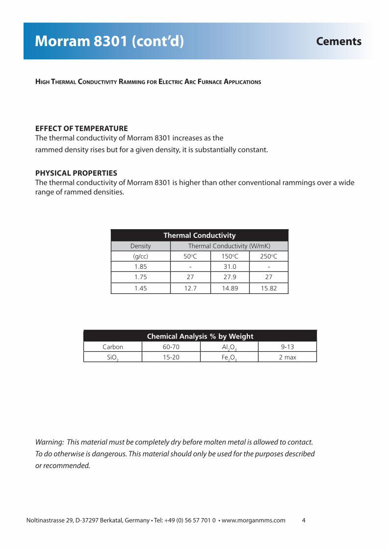
EFFECT OF TEMPERATUREThe thermal conductivity of Morram 8301 increases as therammed density rises but for a given density, it is substantially constant.
PHYSICAL PROPERTIESThe thermal conductivity of Morram 8301 is higher than other conventional rammings over a wide range of rammed densities.
Thermal ConductivityDensity Thermal Conductivity (W/mK)
(g/cc) 50oC 150oC 250oC
1.85 - 31.0 -
1.75 27 27.9 27
1.45 12.7 14.89 15.82
Chemical Analysis % by WeightCarbon 60-70 Al
2O
39-13
SiO2
15-20 Fe2O
32 max
Warning: This material must be completely dry before molten metal is allowed to contact. To do otherwise is dangerous. This material should only be used for the purposes described or recommended.
Thermal ConductivityDensity Thermal Conductivity (W/mK)
(g/cc) 50oC 150oC 250oC
1.85 - 31.0 -
1.75 27 27.9 27
1.45 12.7 14.89 15.82
Chemical Analysis % by WeightCarbon 60-70 Al
2O
39-13
SiO2
15-20 Fe2O
32 max

Noltinastrasse 29, D-37297 Berkatal, Germany • Tel: +49 (0) 56 57 701 0 • www.morganmms.com 5
PD Coating
PD Coating is a high purity, high alumina coating which is sintered onto the internal surface of the crucible during the manufacturing process. As a result of this process a dense physical barrier is formed which can enhance performance and extend crucible life when used in a range of applica-tions.
FEATURES• Flux Absorption• Prevention of dross adhesion• Prevention of contamination of the melt by crucible body material• Wear resistance
TYPICAL APPLICATIONS• Aluminium alloys (particularly effective at preventing attack on crucible body by aggressive modifying agents such as sodium, sodium salts, strontium).• Zinc distillation and zinc oxide production• Precious metals
Note:PD Coating can be supplied on any of the carbon bonded silicon carbide or clay graphite crucibles manu-factured by Morgan Molten Metal Systems.
Coating

Noltinastrasse 29, D-37297 Berkatal, Germany • Tel: +49 (0) 56 57 701 0 • www.morganmms.com 6
PRO Coating
PRO Coating is a thin covering that can be used on crucibles to significantly reduce impurities when melting and holding pure alloys. It also stops dross build up and makes clean up easy.
PREHEATING/FIRST USEPRO Coating does not impact or change in any way the installation or startup / heating procedures for the crucible in which it has been applied.
APPLICATIONPRO Coating can be mixed with water and applied to the crucible with a brush.It can also be used as a mortar to repair areas that may have been damaged or chipped.
TECHNICAL DATAPrimary material: Sintered Alumina The coating is chemically bonded.Shelf life: 6 monthsMaximum temperature: 1600o C
HOW TO USE To ensure the highest purity of the metal to be melted and to prohibit the build up of dross, a thin layer of PRO Coating should be applied after every charge.
Coating

Noltinastrasse 29, D-37297 Berkatal, Germany • Tel: +49 (0) 56 57 701 0 • www.morganmms.com 7
ADVANTAGES• Easy handling - Allows for quick and easy movement of crucibles without removing the furnace top cover.• Economical• Crucible can be lifted through top opening without removing the furnace top cover, reducing down-time and saving valuable man hours• Prevents damage to heater panels and eliminates costly repairs, as furnace top can be left in place.• Carries CE mark for safety
Minimum In-side Diameter
(mm)
Maximum In-side Diameter
(mm)
Maximum Lift-ing Capacity
(kg)Size 1 350 600 175Size 2 580 740 300Size 3 720 840 500Size 4 820 1000 700Size 5 940 1070 1000
1. Assemble the lifter to the crucible in such a way, that all 3 clamps have the same distance from the crucible top. 2. Move the sliding sleeve pos. 4 until the next free drilling and secure it there with the locking screw pos. 2. 3. Turn the sliding sleeve pos. 4 manually until all 3 clamps suit at the crucible. 4. The sliding sleeve can be manually tighten close over the clamping arm. 5. Avoid for safety reasons any jerky lifting movements. 6. Turn the sliding sleeve pos. 4 to the top after use, in order to protect the thread from getting dirty. 7. The thread should be controlled regularly to be easy movable and should the situation arise dope it with graphite powder.
ATTENTION STRICTLY FORBIDDEN: DO NOT STAND UNDER OR NEAR A SUSPENDED LOAD! WHEN LIFTING USED CRUCIBLES OUT OF THE FURNACE, GREAT CARE MUST BE TAKEN TO AVOID ANY BURST OUT OF THE CRUCIBLE. USE THE CRUCIBLE LIFTER FOR TRANSPORTING THE CRUCIBLE ONLY IN THE IMMEDIATE FRONT AREA OF THE FURNACE TO ELIMINATE ANY SAFETY HAZARDS (INSTALLATION AND DEMOUNTING).
Internal Crucible Lifter Crucible Lifter

Noltinastrasse 29, D-37297 Berkatal, Germany • Tel: +49 (0) 56 57 701 0 • www.morganmms.com 8
One of the major concerns in the modern aluminum casting industry is aluminum alloy cleanliness. With the ever increasing demands for improved casting properties, the requirements for molten metal cleanliness has become extremely stringent. The removal of dissolved hydrogen and unwant-ed particles from the melt using rotary degassing has become a widely used foundry practice. MorganMMS has developed a one piece silicon carbide rotor and shaft for use in this process. The MorganMMS rotary degassing rotor has a high resistance to wear in service and has excellent anti oxidation properties providing a cost effective consumable for use in foundries’ degassing processes. MorganMMS’ degassing rotor can be supplied in a range of sizes to suit customer’s applications.FEATURES• One piece shaft and rotor• Wear resistant silicon carbide material• Excellent oxidation resistance• Rotor designed for good gas dispersal• Six vane rotor to reduce bubble size for better hydrogen removalADVANTAGES• Efficient removal of hydrogen and unwanted particles• Quick changeover of rotor• One piece construction• Long life
SiC Degassing Rotors
00 0.5 1.0 1.5 2.0 2.5 3.0 3.5 4.0 4.5 5.0 5.5
200
400
600
800
1000
1200
1400
Time (h)
Temperature (mC)
After first use
First heat up, and after longer cool off phase
Degassing
• Cost effectiveTests show significantly lower oxidation levels at operating temperatures for the MorganMMS silicon carbide rotor than for leading competitive products in other materials.
The MorganMMS degassing rotor is currently available with a rotor diameter of 150mm in lengths up to 1200mm to suit customer require-ments.
ANTI VORTEX PLATETo complement our degassing rotor, MorganMMS also produces a clay graphite anti vortex plate. This plate is manufactured in a proven wear and oxidation resistant material. It will help stop the reintroduction of hydrogen and aluminium oxide particles into the treated molten aluminium by reducing the circular metal flow caused by the rotation of the degassing rotor.
Reference Number Length
1580388 4201580395 4501580400 5001580510 650
Noltinastrasse 29, D-37297 Berkatal, Germany • Tel: +49 (0) 56 57 701 0 • www.morganmms.com 9
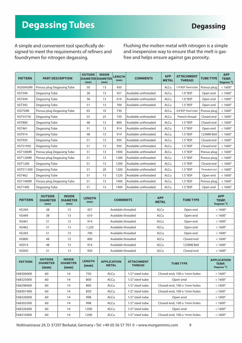
Degassing Tubes
A simple and convenient tool specifically de-signed to meet the requirements of refiners and foundrymen for nitrogen degassing.
PATTERN PART DESCRIPTIONOUTSIDE
DIAMETER(mm)
INSIDE DIAMETER
(mm)
LENGTH(mm) COMMENTS APP
METALATTACHMENT
THREAD TUBE TYPEAPP
TEMP.Degrees °C
VGI50450RI Porous plug Degassing Tube 50 13 450 Al,Cu 1/4 BSP Steel tube Porous plug < 1600°
VGT394 Degassing Tube 38 13 457 Available unthreaded Al,Cu 1.0” BSP Open end < 1600°
VGT449 Degassing Tube 38 13 610 Available unthreaded Al,Cu 1.0” BSP Open end < 1600°
VGT392 Degassing Tube 51 13 700 Available unthreaded Al,Cu 1.5” BSP Open end < 1600°
VGI750RI Porous plug Degassing Tube 65 10 730 Al,Cu 3/8 BSP Steel tube Porous plug < 1600°
VGT55750 Degassing Tube 55 23 750 Available unthreaded Al,Cu French thread Closed end < 1600°
VGT800 Degassing Tube 48 13 800 Available unthreaded Al,Cu 1.5” BSP Closed end < 1600°
VGT461 Degassing Tube 51 13 914 Available unthreaded Al,Cu 1.5” BSP Open end < 1600°
VGT914 Degassing Tube 48 13 914 Available unthreaded Al,Cu 1.5” BSP 125MM Bell < 1600°
VGT950 Degassing Tube 51 13 950 Available unthreaded Al,Cu 1.5” BSP Closed end < 1600°
VGT51950 Degassing Tube 51 13 950 Available unthreaded Al,Cu 1.5” BSP Closed end < 1600°
VGT1000RI Porous plug Degassing Tube 51 13 1000 Available unthreaded Al,Cu 1.5” BSP Porous plug < 1600°
VGT1200RI Porous plug Degassing Tube 51 13 1200 Available unthreaded Al,Cu 1.5” BSP Porous plug < 1600°
VGT1200 Degassing Tube 51 13 1200 Available unthreaded Al,Cu 1.5” BSP Closed end < 1600°
VGT511200 Degassing Tube 51 20 1200 Available unthreaded Al,Cu 1.5” BSP Threaded end < 1600°
VGT462 Degassing Tube 51 13 1220 Available unthreaded Al,Cu 1.5” BSP Open end < 1600°
VGT1400RI Porous plug Degassing Tube 51 13 1400 Available unthreaded Al,Cu 1.5” BSP Porous plug < 1600°
VGT1400 Degassing Tube 51 13 1400 Available unthreaded Al,Cu 1.5” BSP Open end < 1600°
Degassing
PATTERNOUTSIDE
DIAMETER(mm)
INSIDE DIAMETER
(mm)
LENGTH(mm) COMMENTS APP
METAL TUBE TYPEAPP
TEMP.Degrees °C
VG394 38 13 457 Available threaded Al,Cu Open end < 1600°
VG449 38 13 610 Available threaded Al,Cu Open end < 1600°
VG461 51 13 914 Available threaded Al,Cu Open end < 1600°
VG462 51 13 1,220 Available threaded Al,Cu Open end < 1600°
VG392 51 13 700 Available threaded Al,Cu Open end < 1600°
VG800 48 13 800 Available threaded Al,Cu Closed end < 1600°
VG914 48 13 914 Available threaded Al,Cu 125MM Bell < 1600°
VG950 51 13 950 Available threaded Al,Cu Closed end < 1600°
PATTERNOUTSIDE
DIAMETER(mm)
INSIDE DIAMETER
(mm)
LENGTH(mm)
APPLICATIONMETAL
ATTACHMENTTHREAD TUBE TYPE
APPLICATION TEMP.
Degrees °C
168300400 60 14 750 Al,Cu 1/2” steel tube Closed end, 100 x 1mm holes < 1600°
168325000 60 14 800 Al,Cu 1/2” steel tube Open end < 1600°
168298400 60 14 800 Al,Cu 1/2” steel tube Closed end, 100 x 1mm holes < 1600°
168301400 60 14 850 Al,Cu 1/2” steel tube Closed end, 100 x 1mm holes < 1600°
168326000 60 14 998 Al,Cu 1/2” steel tube Open end < 1600°
168302500 60 14 998 Al,Cu 1/2” steel tube Closed end, 100 x 1mm holes < 1600°
168326400 60 14 1200 Al,Cu 1/2” steel tube Open end < 1600°
168310400 60 14 1200 Al,Cu 1/2” steel tube Closed end, 100 x 1mm holes < 1600°
Flushing the molten metal with nitrogen is a simple and inexpensive way to ensure that the melt is gas-free and helps ensure against gas porosity.

Noltinastrasse 29, D-37297 Berkatal, Germany • Tel: +49 (0) 56 57 701 0 • www.morganmms.com 10
Dipping Samplers / Dipping Spoons
Sample spoons with an integral handle for taking small samples of molten metal for analysis or for removing dirt and dross from small crucibles.
Metal Sampling and Casting
PATTERN DIAMETER(mm)
LENGTH(mm)
CAPACITY(cc) COMMENTS APPLICATION
METALCAPACITY
(kg) Al
APPLICATION TEMP.
Degrees °C
VB56 44 241 10 Al,Au,Ag sampling Al,Cu,Ag,Au 0.023 < 1600°
VB35 60 335 10 Al,Au,Ag sampling Al,Cu,Ag,Au 0.023 < 1600°
VB66 51 356 30 Al,Au,Ag sampling Al,Cu,Ag,Au 0.075 < 1600°
VB394 30 394 5 Al,Au,Ag sampling Al,Cu,Ag,Au 0.012 < 1600°
VB316 44 457 10 Al,Au,Ag sampling Al,Cu,Ag,Au 0.023 < 1600°
VB590 30 590 5 Al,Au,Ag sampling Al,Cu,Ag,Au 0.012 < 1600°

Noltinastrasse 29, D-37297 Berkatal, Germany • Tel: +49 (0) 56 57 701 0 • www.morganmms.com 11
Ladle Bowls
The best method of taking molten metal samples and for skimming slag from induction furnaces and ladles. The products are supplied in a range of sizes from 275 cm3 to 2000 cm3 capacity. De-signed for obtaining samples for spectrographic analysis, test bars and thermal analysis samples. Molten metal samples can be retrieved in a cost efficient way, free from contamination of dirt, which is close to temperature of the bulk metal being sampled (important for thermal analysis).
Metal Sampling and Casting
TYPE DRAIN HOLES CAPACITY USESNB10 * 0 275cc 1.8kg iron Taking molten metal samples for analysis
NB20 * 0 1100cc 7.5kg iron Casting test bars and small castings
NB30 * 0 2000cc 14.0kg iron Molten metal transfer and small castings
NB31 * 1 2000cc N/A Removing slag from ladles and Induction Furnaces
VB6A < 0 90cc 0.6kg iron Taking molten metal samples for analysis
VB18A < 0 260cc 1.8kg iron Taking molten metal samples for analysis
VB18/3A < 3 260cc N/A Removing dross and slag from small casting ladles
VB4A < 0 295cc 2.0kg iron Taking molten metal samples for analysis
VB5A < 0 510cc 3.6kg iron Casting test bars and small castings
VB8/2A < 6 1800cc N/A Removing slag from ladles and Induction Furnaces
VB8A < 0 1800cc 13.75kg iron Metal transfer and small castings
VB8/4A * 1 1800cc N/A Removing slag from ladles and Induction Furnaces
VB8/5A < 1 1800cc N/A Removing slag from ladles and Induction Furnaces
VB25 < 0 3170cc 22.0kg iron Molten metal transfer
VB271 < 0 4000cc 28.0kg iron Molten metal transfer
NB28/5 * 5 N/A N/A Removing slag and dross from ladles and autopours
NB32/1 * 1 N/A N/A Removing slag from ladles and Induction Furnaces
NB32/4 < 4 N/A N/A Removing slag from ladles and Induction Furnaces

Noltinastrasse 29, D-37297 Berkatal, Germany • Tel: +49 (0) 56 57 701 0 • www.morganmms.com 12
Metal Sampling and Casting+GF+ Converter Segments
MorganMMS’ +GF+ converter segments offer an economic alternative consumable for found-ries converting cast iron to ductile iron using the George Fischer process. Produced in clay graphite under quality controlled conditions, MorganMMS’ converter segments can be manu-factured in a range of sizes to suit customers’ requirements.
APPLICATIONThe segments are placed in the bottom of the George Fischer converter vessel to form a cham-ber into which the magnesium is introduced from outside the vessel. When the vessel is rotated, the molten iron is introduced into the chamber in a controlled manner through the holes in the clay graphite segment. The magne-sium is then vaporised by the iron and desulphu-rises and nodularises the cast iron, producing ductile cast iron.
Clay Graphite segment in position in converter
+GF+ CONVERTER SEGMENT SIZES
DRGNO
LENGTHmm
HEIGHTmm
WALL THICKNESSmm
APPROXIMATE METAL CAPACITY
SEGMENT 393 658 840 65 3T
SEGMENT 366 599 760 70 2T
SEGMENT 328 587 640 50 2T
SEGMENT 327 564 560 50 1.1T
SEGMENT 420 850 760 70 3T
SEGMENT 421 658 840 65 3T
SEGMENT 422 720 830 50 2.2T
SEGMENT 428 841 760 70 2T
SEGMENT 432 901 1020 70 4T
All dimensions are subject to normal manufacturing tolerances
MorganMMS reserve the right to change specifications at any time.

Noltinastrasse 29, D-37297 Berkatal, Germany • Tel: +49 (0) 56 57 701 0 • www.morganmms.com 13
Downspouts
PATTERNOUTSIDE
DIAMETER(mm)
INSIDE DIAMETER
(mm)
LENGTH(mm)
FLANGE DIAMETER
(mm)COMMENTS APPLICATION
METALOUTLET HOLES
APPLICATION TEMP.
Degrees °C
WX90 65 36 90 75 Cu 1 < 1600°
WX3 62 38 102 70 Cu 1 < 1600°WX122A 95 55 103 122 Cu 1 < 1600°WX120 44 25 120 51 Cu 1 < 1600°WX48 48 35 120 60 Cu 1 < 1600°WX128 70 30 128 85 Cu 1 < 1600°WX130 35 15 130 52 Cu 1 < 1600°WX115 90 70 140 115 Cu 8 < 1600°WX145 60 30 145 90 Cu 8 < 1600°WX122 95 55 147 122 Cu 1 < 1600°WX140 79 25 156 140 Cu 1 < 1600°
WX654 43 18 181 88 Od Tapers to 37mm Cu 1 < 1600°
WX38186 38 22 186 46 Cu 1 < 1600°WX187 76 35 187 108 Cu 2 < 1600°WX278 50 22 190 75 Cu 2 < 1600°WX68200 68 45 200 68 Cu 4 < 1600°WX77200 77 44 200 87 Cu 1 < 1600°WX210 45 25 210 80 Cu 2 < 1600°WX684 44 19 216 83 Cu 1 < 1600°WX6841 44 19 216 83 Cu 1 < 1600°
WX6842 44 15 216 83 Od Tapers to 26mm Cu 1 < 1600°
WX685 44 13 216 83 Cu 1 < 1600°WX220 45 25 220 80 Cu 2 < 1600°
WX655 43 25 254 88 Od Tapers to 37mm Cu 1 < 1600°
WX687 44 17 260 88 Cu 1 < 1600°WX300 70 20 300 100 Cu 2 < 1600°WX310 63 23 310 75 Cu 2 < 1600°
Metal Transfer

Noltinastrasse 29, D-37297 Berkatal, Germany • Tel: +49 (0) 56 57 701 0 • www.morganmms.com 14
PATTERNOUTSIDE
DIAMETER(mm)
INSIDE DIAMETER
(mm)
LENGTH(mm)
FLANGE DIAMETER
(mm)COMMENTS APPLICATION
METALOUTLET HOLES
APPLICATION TEMP.
Degrees °C
WX90 65 36 90 75 Cu 1 < 1600°
WX3 62 38 102 70 Cu 1 < 1600°WX122A 95 55 103 122 Cu 1 < 1600°WX120 44 25 120 51 Cu 1 < 1600°WX48 48 35 120 60 Cu 1 < 1600°WX128 70 30 128 85 Cu 1 < 1600°WX130 35 15 130 52 Cu 1 < 1600°WX115 90 70 140 115 Cu 8 < 1600°WX145 60 30 145 90 Cu 8 < 1600°WX122 95 55 147 122 Cu 1 < 1600°WX140 79 25 156 140 Cu 1 < 1600°
WX654 43 18 181 88 Od Tapers to 37mm Cu 1 < 1600°
WX38186 38 22 186 46 Cu 1 < 1600°WX187 76 35 187 108 Cu 2 < 1600°WX278 50 22 190 75 Cu 2 < 1600°WX68200 68 45 200 68 Cu 4 < 1600°WX77200 77 44 200 87 Cu 1 < 1600°WX210 45 25 210 80 Cu 2 < 1600°WX684 44 19 216 83 Cu 1 < 1600°WX6841 44 19 216 83 Cu 1 < 1600°
WX6842 44 15 216 83 Od Tapers to 26mm Cu 1 < 1600°
WX685 44 13 216 83 Cu 1 < 1600°WX220 45 25 220 80 Cu 2 < 1600°
WX655 43 25 254 88 Od Tapers to 37mm Cu 1 < 1600°
WX687 44 17 260 88 Cu 1 < 1600°WX300 70 20 300 100 Cu 2 < 1600°WX310 63 23 310 75 Cu 2 < 1600°
Filling Funnels Metal Transfer
PATTERN PART DESCRIPTION
TOP DIAMETER
(mm)
BTM. DIAMETER
(mm)
HEIGHT(mm)
HOLE DIA.(mm)
COMMENTS APPLICATIONMETAL
APPLICATION TEMP.
Degrees °C
NR1 Filling Funnel 265 90 510 0.98 available with 40mm hole Al < 1000°
NR2 Filling Funnel 300 90 605 0.98 available with 40mm hole Al < 1000°
NR3 Filling Funnel 300 90 620 0.98 available with 40mm hole Al < 1000°
NR4 Filling Funnel 300 87 725 0.98 available with 40mm hole Al < 1000°
NR5 Filling Funnel 300 87 838 0.98 available with 40mm hole Al < 1000°

Launders
Pre-fired shapes for the transfer of ferrous and non-ferrous metals from furnace to furnace or from furnace to ladle. Launders provide a metal transfer system that has a high resistance to erosion and is virtually maintenance-free when installed properly. Available in many sizes to suit most runner systems. Also suitable for use as spouts in “teapot” spout casting ladles.
Metal Transfer
PATTERN WIDTH DEPTH LENGTH COMMENTS APPLICATIONMETAL
CHANNEL APP. TEMP
(mm) (mm) (mm) (mm) Degrees °C
N3/580 160 80 1040 Al,Cu,Fe 98 X 45 < 1600N3/350 162 102 350 Al,Cu,Fe 102 X 67 < 1600N3/375 162 102 405 Al,Cu,Fe 102 X 67 < 1600N3/50A 162 102 540 Al,Cu,Fe 102 X 67 < 1600N3/377 162 102 560 Al,Cu,Fe 102 X 67 < 1600N3/376 162 102 570 Al,Cu,Fe 102 X 67 < 1600N3/379 162 102 700 Al,Cu,Fe 102 X 67 < 1600N3/372 162 102 840 Al,Cu,Fe 102 X 67 < 1600N3/50 162 102 1000 Al,Cu,Fe 102 X 67 < 1600N3/371 162 102 1100 Al,Cu,Fe 102 X 67 < 1600N3/374 162 102 1220 Al,Cu,Fe 102 X 67 < 1600N3/667 162 152 610 Al,Cu,Fe 108 X 117 < 1600N3/665 162 152 840 Al,Cu,Fe 108 X 117 < 1600N3/666 162 152 1145 Al,Cu,Fe 108 X 117 < 1600N3/6 274 255 1219 Al,Cu,Fe 178 X 178 < 1600N3/6H 274 255 1219 Al,Cu,Fe 178 X 111 < 1600
SRG 170/200 150 85 200 170mm flange Al,Cu,Fe 90 X 50 < 1600SRG 170/215 150 85 215 170mm flange Al,Cu,Fe 90 X 50 < 1600SRG 170/275 150 85 275 170mm flange Al,Cu,Fe 90 X 50 < 1600SRG 170/325 150 85 325 170mm flange Al,Cu,Fe 90 X 50 < 1600SRG 170/360 150 85 360 170mm flange Al,Cu,Fe 90 X 50 < 1600SRG 170/500 150 85 500 170mm flange Al,Cu,Fe 90 X 50 < 1600SRG 140/280 120 115 280 140mm flange Al,Cu,Fe 70 X 70 < 1600SRG 220/275 200 120 275 220mm flange Al,Cu,Fe 130 X 70 < 1600
SRG 220/375 200 120 375 220mm flange Al,Cu,Fe 130 X 70 < 1600

Noltinastrasse 29, D-37297 Berkatal, Germany • Tel: +49 (0) 56 57 701 0 • www.morganmms.com 16
Needle Valves
PATTERN OUTSIDE DIAMETER
(mm)
LENGTH(mm)
NOSE(mm)
APPLICATIONMETAL
APPLICATION TEMP.
Degrees °C
VJ1001 45 80 Round Al,Cu,Fe < 1600°
RV682 51 203 60 Al,Cu,Fe < 1600°
RV220 42 220 45 Al,Cu,Fe < 1600°
RV676 51 241 60 Al,Cu,Fe < 1600°
RV6762 49 241 20 Al,Cu,Fe < 1600°
RV250 42 250 45 Al,Cu,Fe < 1600°
RV265 50 265 45 Al,Cu,Fe < 1600°
RV267 51 267 60 Al,Cu,Fe < 1600°
RV340 50 340 60 Al,Cu,Fe < 1600°
RV394 32 394 15 Al,Cu,Fe < 1600°
RV50480 50 480 60 Al,Cu,Fe < 1600°
RV584 50 584 60 Al,Cu,Fe < 1600°
RV584G 50 584 60 Al,Cu,Fe < 1600°
RV20600 20 600 Round Al,Cu,Fe < 1600°
RV815 60 615 60 Al,Cu,Fe < 1600°
RV686 46 686 75 Al,Cu,Fe < 1600°
RV686G 46 686 75 Al,Cu,Fe < 1600°
RV380 70 800 60 Al,Cu,Fe < 1600°
RV80845 80 845 60 Al,Cu,Fe < 1600°
RV80900G 80 900 60 Al,Cu,Fe < 1600°
Clay graphite needle valves provide accurate control over the flow of molten metal in continuous casting applications.
Metal Transfer

Noltinastrasse 29, D-37297 Berkatal, Germany • Tel: +49 (0) 56 57 701 0 • www.morganmms.com 17
Stoppers
A complete range of Salamander PlumbagoTM stoppers for bottom pour ladles is available in a range of sizes and designs. MorganMMS stop-per rod ends are used by attaching to a steel rod, which is sheathed with refractory tubes for protection from the molten metal.Our stoppers do not stick to the ladle nozzle when lifted and consistently reseal without leaks when closed off.
Metal Transfer
PATTERN PART DESCRIPTION
TOP DIAMETER
(mm)
BTM. DIAMETER
(mm)
LENGTH(mm)
APPLICATIONMETAL
THREAD DIA.(mm)
NOSE RADIUS
(mm)
MAXIMUM TEMP.
Degrees °C
RS.2 Standard Stopper 92 88 87 Steel N/A 35 1600°RS.52 Morlok Stopper 92 88 87 Steel M20 35 1600°RS.53 Morlok Stopper 102 96 88 Steel M20 29 1600°
RS.21 Internal thread stopper 59 58 108 Steel 25 29 1600°
RS.22 Internal thread stopper 89 86 114 Steel 28 43 1600°
RS.23 Internal thread stopper 100 88 130 Steel 38 44 1600°
RS.26 Internal thread stopper 130 110 130 Steel 37 55 1600°
RS.24 Internal thread stopper 113 102 142 Steel 37 51 1600°

Noltinastrasse 29, D-37297 Berkatal, Germany • Tel: +49 (0) 56 57 701 0 • www.morganmms.com 18
Stoppers Metal Transfer
A complete range of Salamander stoppers for bottom pour ladles is available in a range of sizes and designs.
AD
F
C
B
G E
R
A
C
B
GD
F
RE
NOMINAL DIA
PATTERN NO. A B C D E F G R P
90 S.0 90 80 120 68 62 33.5 23.5 13 12 40 6
105 S.1 105 90 130 78 72 38.5 28.5 13 12 45 6
120 S.2 120 110 125 86 72 38.5 28.5 13 12 55 6
140 S.3 140 120 145 86 72 38.5 28.5 13 12 60 6
155 S.4/2 155 130 155 97 82 38.5 28.5 13 12 65 6
170 S.5 170 130 170 115 97 38.5 28.5 13 12 65 6
NOMINAL DIA
PATTERN NO. A B C D E F G R P
90 RS.22 89 86 114 57 56 28 21 13 10 43 6
100 RS.23 100 88 130 64 62 38 28 13 10 44 6
115 RS.24 115 102 142 70 68 38 28 12 10 51 6
130 RS.26 130 110 130 72 70 37 28 12 10 55 6
NOMINAL DIA
PATTERN NO. A B C D E F G R P BORE
DIA90 RS 395 90 84 100 64/63 58/50 12 10 44 4 28
100 RS 431 102 102 103 76/68 57/47.5 12 12 51 4 32
100 RS 439 102 102 103 76/68 57/47.5 12 12 51 4 34
100 RS 442 102 102 102 64/63 57/47.5 12 9.5 51 4 28
115 RS 415 114.5 111 108 79.5/76 57/47.5 12 24 55.5 5 32
115 RS 441 114.5 111 108 79.5/76 57/47.5 12 12 55.5 4 32
120 RS 438 120 104 125 82/69 69/59.5 12 9.5 52 4 43
120 RS 414 152.5 150 149 89/90 101.5/92 12 17 101.5 5 54
Due to the properties of Salamander these stoppers provide an efficient, cost effective seal on the ladle nozzle.
Ee
18
G
CR51R
2
1
ADd Split Insert
(XA00225)
F
H
I
RED DIAMOND STOPPER HEAD PHYSICAL PROPERTIESAPPARENT POROSITY: 20 - 28%BULK DENSITY: 2.1 - 2.3 gm/cc.C.C.S.: 200 - 300 KG/CM2P.C.E.: 35 - 37 Orton Cone
RED DIAMOND STOPPER HEAD CHEMICAL COMPOSITIONCARBON: 12 - 14%AL203: 52 - 54%SIO2.: 25 - 27%OTHER: 5 - 10%

Noltinastrasse 29, D-37297 Berkatal, Germany • Tel: +49 (0) 56 57 701 0 • www.morganmms.com 19
Tiles Metal Transfer
PATTERN PART DESCRIPTION THICKNESS(mm)
LENGTH(mm)
WIDTH(mm) COMMENTS APPLICATION
METAL
APPLICATION TEMP.
Degrees °C
N27/1 TAP HOLE BLOCK 76 114 114 Al,Cu,Fe < 1600°
N27/1ATAP HOLE BLOCK 25mm 76 114 114 Al,Cu,Fe < 1600°
N27/30TAP HOLE BLOCK 30mm 76 114 114 Al,Cu,Fe < 1600°
N25/178A TILE 25 130 95 Al,Cu,Fe < 1600°N25/152 SKIMMER BLOCK 35 152 102 Al,Cu,Fe < 1600°N25/73 TILE 25 152 152 Al,Cu,Fe < 1600°N25/178 SKIMMER BLOCK 25 178 95 Al,Cu,Fe < 1600°N27/2 TAP HOLE BLOCK 76 228 114 Al,Cu,Fe < 1600°N25/305 SKIMMER BLOCK 51 254 127 Taper to 38mm Al,Cu,Fe < 1600°N25/290 TILE 25 290 260 Al,Cu,Fe < 1600°N25/94 TILE 25 685 228 Al,Cu,Fe < 1600°

Tubes
For “teapot” pour ladles, cupola receiver entries and spouts, cupola slagging box syphons, or for any metal transfer operation. Clay graphite tubes are available in a range of sizes from 25 to 250mm diameter and lengths up to 1400mm (large diameter tubes, over 200mm od, can be manufactured up to 1900mm long).
Metal Transfer
PATTERN PART DESCRIPTION
OUTSIDE DIA
INSIDE DIA LENGTH WALL APPLICATION
APPLICATION TEMP.
(mm) (mm) (mm) (mm) METAL Degrees °C
N12/56 TUBE 143 108 200 17.5 Al,Cu,Fe < 1600VG255 TUBE 34 19 255 7.5 Al,Cu,Fe < 1600VG267 TUBE 178 127 267 25.5 Al,Cu,Fe < 1600VG269 TUBE 180 122 267 29 Al,Cu,Fe < 1600N12/79 TUBE 100 38 300 31 Al,Cu,Fe < 1600VG350 TUBE 68 45 350 11.5 Al,Cu,Fe < 1600VG1547 TUBE 170 133 368 18.5 Al,Cu,Fe < 1600N12/68 TUBE 100 51 400 24.5 Al,Cu,Fe < 1600VG1590 TUBE 125 85 406 20 Al,Cu,Fe < 1600N12/64 TAPHOLE TUBE 89 60 425 14.5 Al,Cu,Fe < 1600N12/38 TUBE 100 51 457 24.5 Al,Cu,Fe < 1600N12/34 TUBE 200 150 500 25 Al,Cu,Fe < 1600N12/70 TUBE 58 38 500 10 Al,Cu,Fe < 1600N12/31 TUBE 143 108 508 17.5 Al,Cu,Fe < 1600N12/51 TUBE 89 60 508 14.5 Al,Cu,Fe < 1600N12/75 TUBE + 45 END 146 89 508 28.5 Al,Cu,Fe < 1600N12/71 TUBE 77 45 600 16 Al,Cu,Fe < 1600N12/66 TUBE 114 89 610 12.5 Al,Cu,Fe < 1600N12/30 TUBE 100 51 632 24.5 Al,Cu,Fe < 1600N12/63 TAPHOLE TUBE 175 110 650 32.5 Al,Cu,Fe < 1600N12/29 TUBE 89 60 762 14.5 Al,Cu,Fe < 1600N12/32C TUBE 143 108 762 17.5 Al,Cu,Fe < 1600N12/90 TUBE + CURVE 123 80 900 21.5 Al,Cu,Fe < 1600N12/950 TUBE 100 12 950 44 Al,Cu,Fe < 1600VG950 Tube 51 13 950 19 Al,Cu,Fe < 1600N12/67 TUBE 143 108 1000 17.5 Al,Cu,Fe < 1600N12/69 TUBE 100 51 1020 24.5 Al,Cu,Fe < 1600N12/32E TUBE 143 108 1070 17.5 Al,Cu,Fe < 1600N12/32 TUBE 143 108 1219 17.5 Al,Cu,Fe < 1600N12/65 TUBE 241 190 1219 25.5 Al,Cu,Fe < 1600N12/72 TUBE + 45 ENDS 125 83 1397 21 Al,Cu,Fe < 1600VG1830 TUBE 241 190 1830 25.5 Al,Cu,Fe < 1600N12/33 TUBE 146 86 1930 30 Al,Cu,Fe < 1600
Noltinastrasse 29, D-37297 Berkatal, Germany • Tel: +49 (0) 56 57 701 0 • www.morganmms.com 21
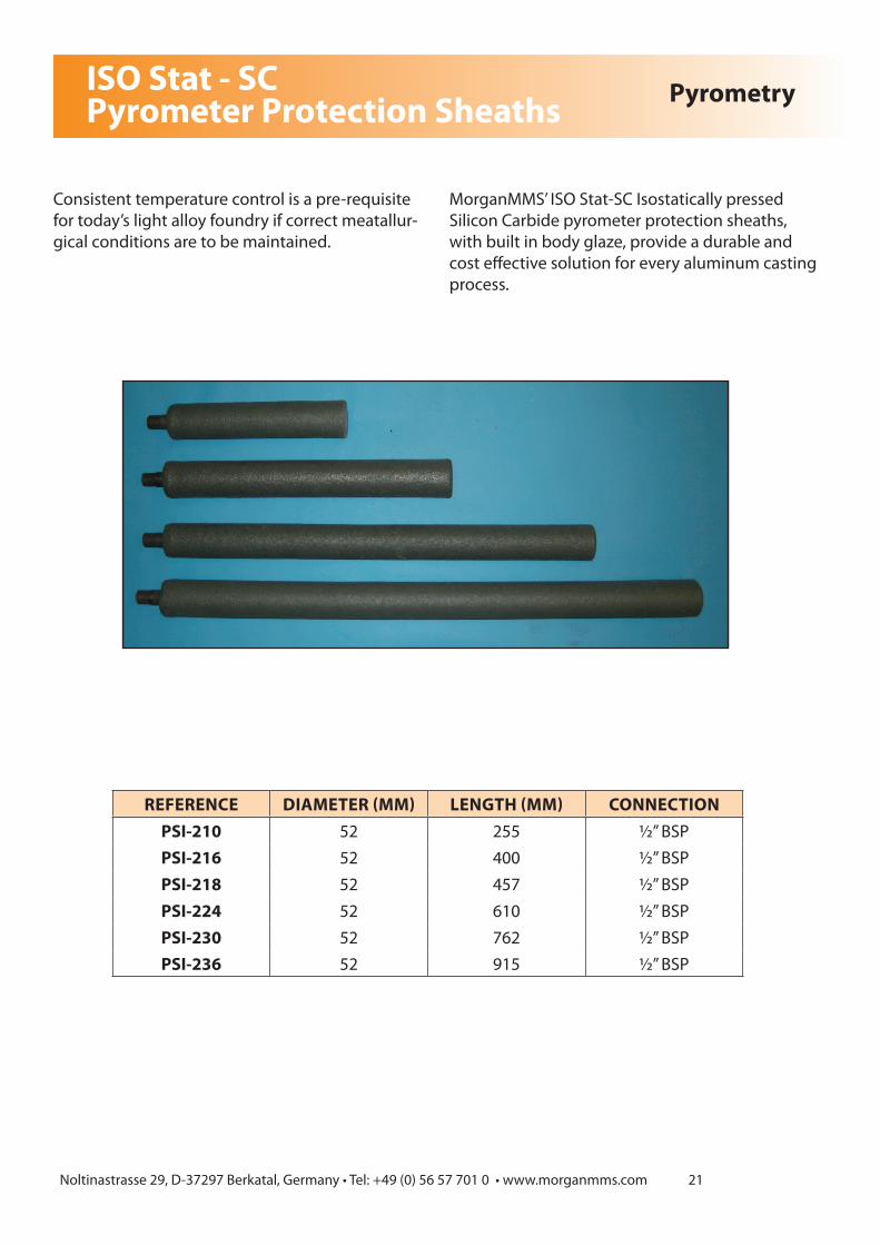
ISO Stat - SC Pyrometer Protection Sheaths Pyrometry
Consistent temperature control is a pre-requisite for today’s light alloy foundry if correct meatallur-gical conditions are to be maintained.
MorganMMS’ ISO Stat-SC Isostatically pressed Silicon Carbide pyrometer protection sheaths, with built in body glaze, provide a durable and cost effective solution for every aluminum casting process.
REFERENCE DIAMETER (MM) LENGTH (MM) CONNECTIONPSI-210 52 255 ½” BSPPSI-216 52 400 ½” BSPPSI-218 52 457 ½” BSPPSI-224 52 610 ½” BSPPSI-230 52 762 ½” BSPPSI-236 52 915 ½” BSP

Noltinastrasse 29, D-37297 Berkatal, Germany • Tel: +49 (0) 56 57 701 0 • www.morganmms.com 22
Pyrometer Sheaths
MorganMMS pyrometer sheaths offer an economic system for the measurement of liquid metal temperature. They provide accuracy and good response and are available for both floating and fixed installations in a range of sizes to suit most applications.
Pyrometry
PATTERNSTEEL
INSERT LENGTHOUTSIDE
DIA INSIDE DIA COMMENTS APP.METAL
FIXINGGROOVE
APPLICATION TEMP.
YES / NO (mm) (mm) (mm) Degrees °C
PR760/25/10A No 760 25 10lengths up to 760
max Al N < 1600
PR760/25/10B No 760 25 10lengths up to 760
max Al Y < 1600
PR760/25/10C No 760 25 10lengths up to 760
max Al N < 1600
PR850/60/25A No 850 60 25lengths up to 850
max Al N < 1600
PR850/60/25B No 850 60 25lengths up to 850
max Al Y < 1600
PR850/60/25C No 850 60 25lengths up to 850
max Al N < 1600
PR1320/40/18A No 1320 40 18lengths up to
1320 max Al N < 1600
PR1320/40/18B No 1320 40 18lengths up to
1320 max Al Y < 1600
PR1320/40/18C No 1320 40 18lengths up to
1320 max Al N < 1600
PR1525/50/25A No 1525 50 25lengths up to
1525 max Al N < 1600
PR1525/50/25B No 1525 50 25lengths up to
1525 max Al Y < 1600
PR1525/50/25C No 1525 50 25lengths up to
1525 max Al N < 1600

Noltinastrasse 29, D-37297 Berkatal, Germany • Tel: +49 (0) 56 57 701 0 • www.morganmms.com 23
Pyrometer Sheaths Pyrometry
PATTERNSTEEL
INSERT LENGTHOUTSIDE
DIAINSIDE
DIA COMMENTS APPLICATIONMETAL
FIXINGGROOVE
APPLICATION TEMP.
YES / NO (mm) (mm) (mm) Degrees °C
TCS106 Yes 150 52 9.5 3/8” Steel tube Al N < 1000TCS206 Yes 150 52 13 1/2” Steel tube Al N < 1000TCS306 Yes 150 60 19 3/4” Steel tube Al N < 1000TCS110 Yes 255 52 9.5 3/8” Steel tube Al N < 1000TCS210 Yes 255 52 13 1/2” Steel tube Al N < 1000TCS310 Yes 255 60 19 3/4” Steel tube Al N < 1000TCS112 Yes 305 52 9.5 3/8” Steel tube Al N < 1000TCS212 Yes 305 52 13 1/2” Steel tube Al N < 1000TCS312 Yes 305 60 19 3/4” Steel tube Al N < 1000TCS116 Yes 405 52 9.5 3/8” Steel tube Al N < 1000TCS216 Yes 405 52 13 1/2” Steel tube Al N < 1000TCS316 Yes 405 60 19 3/4” Steel tube Al N < 1000TCS118 Yes 460 52 9.5 3/8” Steel tube Al N < 1000TCS218 Yes 460 52 13 1/2” Steel tube Al N < 1000TCS318 Yes 460 60 19 3/4” Steel tube Al N < 1000TCS120 Yes 510 52 9.5 3/8” Steel tube Al N < 1000TCS220 Yes 510 52 13 1/2” Steel tube Al N < 1000TCS320 Yes 510 60 19 3/4” Steel tube Al N < 1000TCS122 Yes 560 52 9.5 3/8” Steel tube Al N < 1000TCS222 Yes 560 52 13 1/2” Steel tube Al N < 1000TCS322 Yes 560 60 19 3/4” Steel tube Al N < 1000TCS124 Yes 610 52 9.5 3/8” Steel tube Al N < 1000TCS224 Yes 610 52 13 1/2” Steel tube Al N < 1000TCS324 Yes 610 60 19 3/4” Steel tube Al N < 1000TCS128 Yes 710 52 9.5 3/8” Steel tube Al N < 1000TCS228 Yes 710 52 13 1/2” Steel tube Al N < 1000TCS328 Yes 710 60 19 3/4” Steel tube Al N < 1000TCS130 Yes 760 52 9.5 3/8” Steel tube Al N < 1000TCS230 Yes 760 52 13 1/2” Steel tube Al N < 1000TCS330 Yes 760 60 19 3/4” Steel tube Al N < 1000TCS136 Yes 915 52 9.5 3/8” Steel tube Al N < 1000TCS236 Yes 915 52 13 1/2” Steel tube Al N < 1000TCS336 Yes 915 60 19 3/4” Steel tube Al N < 1000TCS142 Yes 1065 52 9.5 3/8” Steel tube Al N < 1000TCS242 Yes 1065 52 13 1/2” Steel tube Al N < 1000TCS342 Yes 1065 60 19 3/4” Steel tube Al N < 1000TCS148 Yes 1220 52 9.5 3/8” Steel tube Al N < 1000TCS248 Yes 1220 52 13 1/2” Steel tube Al N < 1000TCS348 Yes 1220 60 19 3/4” Steel tube Al N < 1000

Pyrometer Sheaths Pyrometry
PATTERN PART DESCRIPTIONSTEEL
INSERTYES / NO
LENGTH(mm)
OUTSIDE DIA(mm)
INSIDE DIA(mm)
COMMENTS APPLICATIONMETAL
FIXINGGROOVE
APPLICATION TEMP.
Degrees °C
VGI50155 HotRod Yes 155 44 16 R1/2 steel tube Al N < 1000
VGI50203 HotRod Yes 203 44 16 R1/2 steel tube Al N < 1000
VGI50255 HotRod Yes 255 44 16 R1/2 steel tube Al N < 1000
VGI50300 HotRod Yes 300 44 16 R1/2 steel tube Al N < 1000
VGI50400 HotRod Yes 400 44 16 R1/2 steel tube Al N < 1000
VGI50457 HotRod Yes 457 44 16 R1/2 steel tube Al N < 1000
VGI50610 HotRod Yes 610 44 16 R1/2 steel tube Al N < 1000
VGI50650 HotRod Yes 650 44 16 R1/2 steel tube Al N < 1000
VGI50762 HotRod Yes 762 44 16 R1/2 steel tube Al N < 1000
VGI50850 HotRod Yes 850 44 16 R1/2 steel tube Al N < 1000
VGI50914 HotRod Yes 914 44 16 R1/2 steel tube Al N < 1000
VGI501000 HotRod Yes 1000 44 16 R1/2 steel tube Al N < 1000
VGI501067 HotRod Yes 1067 44 16 R1/2 steel tube Al N < 1000
VG664 Pyrometer Sheaths with groove No 152 55 13 Al,Cu Y < 1600
VG618 Pyrometer Sheaths with groove No 267 55 13 Al,Cu Y < 1600
VG277 Pyrometer Sheath No 305 44 25 Al,Cu N < 1600
VG570 Pyrometer Sheath No 320 25 10 Al,Cu N < 1600
VG450 Pyrometer Sheath No 450 51 13 Al,Cu N < 1600
VG572 Pyrometer Sheath No 450 25 10 Al,Cu N < 1600
VG278 Pyrometer Sheath No 457 44 25 Al,Cu N < 1600
VG639 Pyrometer Sheaths with groove No 478 55 13 Al,Cu Y < 1600
VG575 Pyrometer Sheath No 550 25 10 Al,Cu N < 1600
VG290 Pyrometer Sheath No 585 44 25 Al,Cu N < 1600
VG622 Pyrometer Sheath No 622 51 13 Al,Cu N < 1600
VG44700 Pyrometer Sheath No 700 44 25 Al,Cu N < 1600
VG755 Pyrometer Sheath No 750 51 25 Al,Cu N < 1600
VG750 Pyrometer Sheath No 750 51 13 Al,Cu N < 1600
VG1593 Pyrometer Sheaths with groove No 762 55 13 Al,Cu Y < 1600
VG565 Pyrometer Sheath No 762 25 13 Al,Cu N < 1600
VG571 Pyrometer Sheath No 762 25 10 Al,Cu N < 1600
VG800 Pyrometer Sheath No 800 51 13 Al,Cu N < 1600
VG44800 Pyrometer Sheath No 800 44 25 Al,Cu N < 1600
VG50850 Pyrometer Sheath No 850 51 25 Al,Cu N < 1600
VG44850 Pyrometer Sheath No 850 44 25 Al,Cu N < 1600
VG864 Pyrometer Sheath No 864 25 10 Al,Cu N < 1600
VG901 Pyrometer Sheath No 900 70 30 Al,Cu N < 1600
VG279 Pyrometer Sheath No 914 44 25 Al,Cu N < 1600
VG718 Pyrometer Sheaths with groove No 950 55 13 Al,Cu Y < 1600
VG950 Pyrometer Sheath No 950 51 13 Al,Cu N < 1600
VG291 Pyrometer Sheath No 1000 44 25 Al,Cu N < 1600
VG501060 Pyrometer Sheath No 1060 44 25 Al,Cu N < 1600
VG551100 Pyrometer Sheath No 1100 55 20 Al,Cu N < 1600
VG1100 Pyrometer Sheath No 1100 51 13 Al,Cu N < 1600
VG1200 Pyrometer Sheath No 1220 51 13 Al,Cu N < 1600
VG551270 Pyrometer Sheath No 1270 55 20 Al,Cu N < 1600
Noltinastrasse 29, D-37297 Berkatal, Germany • Tel: +49 (0) 56 57 701 0 • www.morganmms.com 25
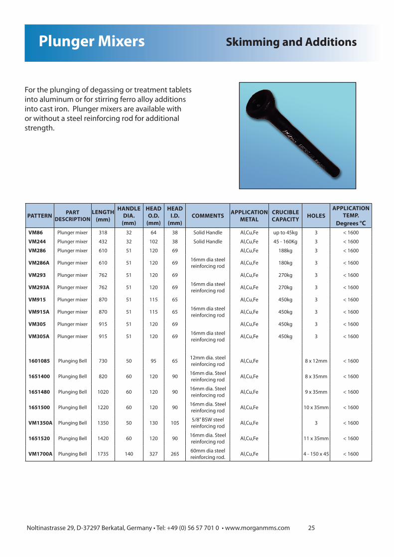
Plunger Mixers
For the plunging of degassing or treatment tablets into aluminum or for stirring ferro alloy additions into cast iron. Plunger mixers are available with or without a steel reinforcing rod for additional strength.
Skimming and Additions
PATTERN PART DESCRIPTION
LENGTH(mm)
HANDLE DIA.
(mm)
HEAD O.D.
(mm)
HEAD I.D.
(mm)COMMENTS APPLICATION
METALCRUCIBLE CAPACITY HOLES
APPLICATION TEMP.
Degrees °CVM86 Plunger mixer 318 32 64 38 Solid Handle Al,Cu,Fe up to 45kg 3 < 1600
VM244 Plunger mixer 432 32 102 38 Solid Handle Al,Cu,Fe 45 - 160Kg 3 < 1600
VM286 Plunger mixer 610 51 120 69 Al,Cu,Fe 188kg 3 < 1600
VM286A Plunger mixer 610 51 120 69 16mm dia steel reinforcing rod Al,Cu,Fe 180kg 3 < 1600
VM293 Plunger mixer 762 51 120 69 Al,Cu,Fe 270kg 3 < 1600
VM293A Plunger mixer 762 51 120 69 16mm dia steel reinforcing rod Al,Cu,Fe 270kg 3 < 1600
VM915 Plunger mixer 870 51 115 65 Al,Cu,Fe 450kg 3 < 1600
VM915A Plunger mixer 870 51 115 65 16mm dia steel reinforcing rod Al,Cu,Fe 450kg 3 < 1600
VM305 Plunger mixer 915 51 120 69 Al,Cu,Fe 450kg 3 < 1600
VM305A Plunger mixer 915 51 120 69 16mm dia steel reinforcing rod Al,Cu,Fe 450kg 3 < 1600
1601085 Plunging Bell 730 50 95 65 12mm dia. steel reinforcing rod Al,Cu,Fe 8 x 12mm < 1600
1651400 Plunging Bell 820 60 120 90 16mm dia. Steel reinforcing rod Al,Cu,Fe 8 x 35mm < 1600
1651480 Plunging Bell 1020 60 120 90 16mm dia. Steel reinforcing rod Al,Cu,Fe 9 x 35mm < 1600
1651500 Plunging Bell 1220 60 120 90 16mm dia. Steel reinforcing rod Al,Cu,Fe 10 x 35mm < 1600
VM1350A Plunging Bell 1350 50 130 105 5/8” BSW steel reinforcing rod Al,Cu,Fe 3 < 1600
1651520 Plunging Bell 1420 60 120 90 16mm dia. Steel reinforcing rod Al,Cu,Fe 11 x 35mm < 1600
VM1700A Plunging Bell 1735 140 327 265 60mm dia steel reinforcing rod. Al,Cu,Fe 4 - 150 x 45 < 1600

Noltinastrasse 29, D-37297 Berkatal, Germany • Tel: +49 (0) 56 57 701 0 • www.morganmms.com 26
Rods
Clay Graphite rods can be used for stirring additions into all types of molten metal ensuring good distribution of the additions in the melt.
Skimming and Additions
PATTERNOUTSIDE
DIAMETER(mm)
LENGTH(mm)
APPLICATIONMETAL
APPLICATION TEMP.
Degrees °C
VR80175 80 175 Al,Cu,Au,Ag,Fe < 1600RS505 50 305 Al,Cu,Au,Ag,Fe < 1600VR83 51 305 Al,Cu,Au,Ag,Fe < 1600VR42 38 355 Al,Cu,Au,Ag,Fe < 1600VR50375G 50 375 Al,Cu,Au,Ag,Fe < 1600VR400 38 400 Al,Cu,Au,Ag,Fe < 1600VR38460 38 460 Al,Cu,Au,Ag,Fe < 1600VR84 25 508 Al,Cu,Au,Ag,Fe < 1600VR50533G 50 533 Al,Cu,Au,Ag,Fe < 1600VR20610 20 610 Al,Cu,Au,Ag,Fe < 1600VR32 32 610 Al,Cu,Au,Ag,Fe < 1600VR610 50 610 Al,Cu,Au,Ag,Fe < 1600VR610G 50 610 Al,Cu,Au,Ag,Fe < 1600VR700G 70 700 Al,Cu,Au,Ag,Fe < 1600VR920 70 920 Al,Cu,Au,Ag,Fe < 1600VR920G 70 920 Al,Cu,Au,Ag,Fe < 1600VR950 51 950 Al,Cu,Au,Ag,Fe < 1600VR451100 45 1100 Al,Cu,Au,Ag,Fe < 1600VR451200 45 1200 Al,Cu,Au,Ag,Fe < 1600VR511200 51 1200 Al,Cu,Au,Ag,Fe < 1600VR1270G 64 1270 Al,Cu,Au,Ag,Fe < 1600VR451400 45 1400 Al,Cu,Au,Ag,Fe < 1600

Noltinastrasse 29, D-37297 Berkatal, Germany • Tel: +49 (0) 56 57 701 0 • www.morganmms.com 27
Skimmers
Clay Graphite skimmers are designed for the easy and efficient removal of dross and dirt from all types of molten metal. They are supplied with a threaded bolt for easy attachment to a handle and have holes for the draining of molten metal back into the furnace, reducing waste.
Skimming and Additions
PATTERN PART DESCRIPTION
DIAMETER(mm)
LENGTH(mm)
CAPACITY(cc) COMMENTS APP
METALBOLT
THREAD DRAIN HOLESAPPLICATION
TEMP.Degrees °C
VK85 Flat Skimmer 64 305 0 Skimming Aluminium dross Al,Cu N/A 19 x 64 mm flat
Skimmer < 1600
VK18 Flat Skimmer 75 460 0 Skimming Aluminium dross Al,Cu N/A 75 x 25 mm Flat
Skimmer < 1600
N25/305 Flat Skimmer 127 254 0 Slagging Lge Induction Fnces Fe 10mm 127 x 51 mm Flat
Skimmer < 1600
VB18/1A Skimmer Bowl 130 160 260 Slagging small ladles Cu,Fe 10mm 1 x 40mm Hole < 1600
VB18/2A Skimmer Bowl 130 160 260 Slagging small ladles Cu,Fe 10mm 1 x 20mm Hole < 1600
VB18/3A Skimmer Bowl 130 160 260 Slagging small ladles Cu,Fe 10mm 3 x 12mm Hole < 1600
NB28/5 Skimmer Spoon 150 209 0 Removing dross and slag Al,Cu,Fe 10mm 5 Holes < 1600
NB28/5A Skimmer Spoon 150 209 0 As NB28/5 with scraper Al,Cu,Fe 10mm 5 holes + Scraper < 1600
NB31 Skimmer Bowl 207 279 2000 Removing dross and slag Al,Cu,Fe 16mm 1 Hole < 1600
VB8/2A Skimmer Bowl 220 260 1800 Slagging large ladles Cu,Fe 16mm 6 Holes < 1600
VB8/4A Skimmer Bowl 220 260 1800 Slagging Induction Fnces. Fe 16mm 1 Hole < 1600
VB8/6A Skimmer Bowl 220 260 1800 Slagging Induction Fnces. Fe 16mm 1 Hole < 1600
VB8/8A Skimmer Bowl 220 260 1800 Slagging Induction Fnces. Fe 16mm 1 Hole < 1600
VB8/5A Skimmer Bowl 230 260 1800 Slagging Induction Fnces. Fe 16mm 1 Hole < 1600
NB32/1 Skimmer Spoon 250 320 0 Slagging Induction Fnces. Cu,Fe 16mm 1 Hole < 1600
NB32/4 Skimmer Spoon 250 320 0 Slagging Induction Fnces. Cu,Fe 16mm 4 Holes < 1600

Noltinastrasse 29, D-37297 Berkatal, Germany • Tel: +49 (0) 56 57 701 0 • www.morganmms.com 28
Stirrers
Clay Graphite stirrers can be used for mix-ing additions into all types of molten metal, ensuring good distribution of the additions in the melt. They can also be used to remove any dirt or oxides from the surface of the molten metal.
Skimming and Additions
PATTERN OUTSIDE DIAMETER
(mm)
LENGTH(mm)
NOSE(mm)
APPLICATIONMETAL
APPLICATION TEMP.
Degrees °C
VS6 22 152 44 Al,Cu,Au,Ag,Fe < 1600VS8 22 203 44 Al,Cu,Au,Ag,Fe < 1600VS12 29 305 57 Al,Cu,Au,Ag,Fe < 1600VS18 38 457 83 Al,Cu,Au,Ag,Fe < 1600VS24 51 610 102 Al,Cu,Au,Ag,Fe < 1600VS26 51 750 150 Al,Cu,Au,Ag,Fe < 1600VS30 51 750 102 Al,Cu,Au,Ag,Fe < 1600

All dimensions are subject to normal manufacturing tolerances. Morgan Molten Metal Systems reserves the right to change specifications at any time. Not responsible for any typographic errors..
Noltinastrasse 29D-37297 Berkatal Germany
Tel: +49 (0) 56 57 701 0Fax: +49 (0) 56 57 701 56
Email: [email protected]: www.morganmms.com