reconfigurable computing - vhdl - types john morris chung-ang university the university of auckland
TRANSCRIPT

Reconfigurable Computing -VHDL - Types
John MorrisChung-Ang University
The University of Auckland

You can give a variablean initial value when youdeclare it!
Types
VHDL is a fully-fledged programming language with a rich type system*
Types includeThose normally found in high level programming
languages integer, character, real, … Example declarations
*Computer scientist’s jargon for “You can make all the data types you need”
VARIABLE a, b : integer := 0; x, y : real := 1.2e-06; p : character;

Types - Defining precision and range Sub-types
Ada (and therefore VHDL) has a very flexible means of specifying exactly the requirements for representations (physical realizations) of numbers
This capability is important for efficient physical realizations If you write VARIABLE x : integer; in your model,
the synthesizer has to `guess’ how many bits of precision that you need for x!
However, if you write VARIABLE x : integer RANGE 0 .. 255; then the compiler knows that an 8-bit representation will be adequate!
Specifying the range of a data type is essential for efficient implementation
• You don’t want the synthesizer to generate a 32-bit adder/subtracter/multiplier/… when an 8-bit one would do!

Literals – or constants
Most literals are similar to other languages Integers – 0, 1, +1, -5, … Reals – 0.0, 3.24, 1.0e+6, -6.5e-20, … Characters – ‘A’, ‘a’, ‘(’, … Strings (formally arrays of characters) –
“clockA”, “data”, …
Numbers in non-decimal bases For efficient digital circuit modeling, we need to specify
numbers in binary, octal, hexadecimal Ada and VHDL use a form:
base#number# Examples:
2#001110#, 8#76771#, 16#a5a5#
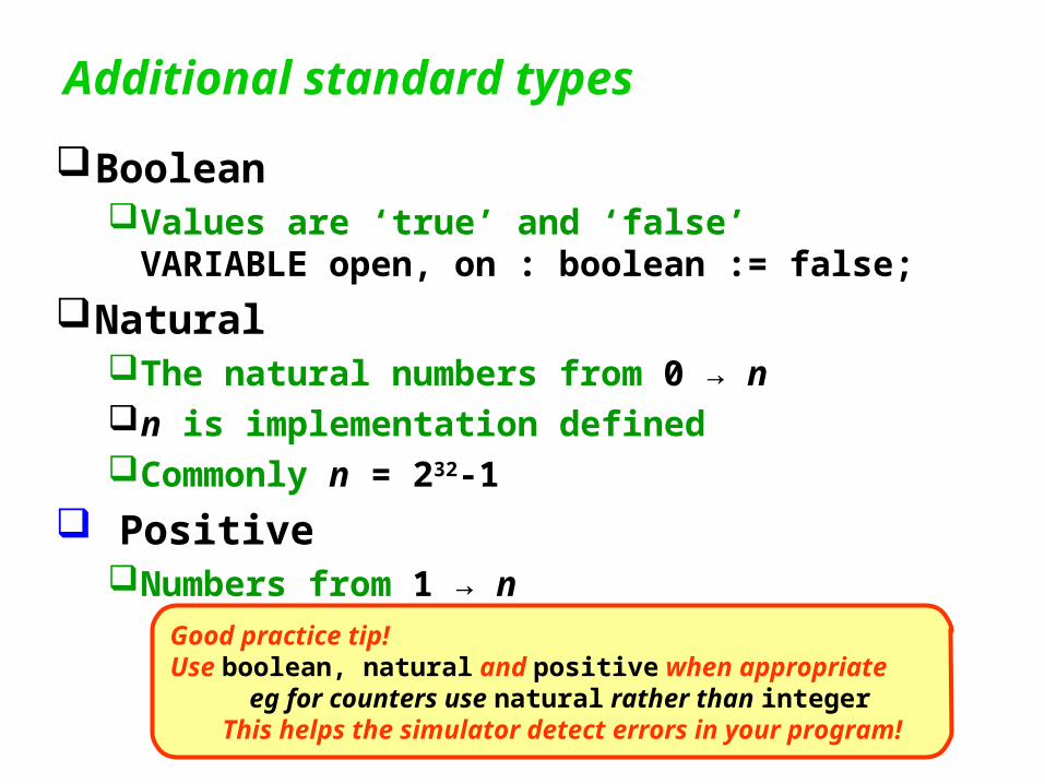
Additional standard types
BooleanValues are ‘true’ and ‘false’VARIABLE open, on : boolean := false;
NaturalThe natural numbers from 0 → nn is implementation definedCommonly n = 232-1
PositiveNumbers from 1 → n
Good practice tip!Use boolean, natural and positive when appropriate
eg for counters use natural rather than integerThis helps the simulator detect errors in your program!

Libraries
VHDL’s standard defines a number of libraries or ‘package’s (using the Ada term)
The most useful is the IEEE 1164 standard logic packageTo use it, add to the start of your program:
This library is just a VHDL package You can usually find the source of it on your system It is worthwhile looking through it …
it provides many useful examples of VHDL capabilities!
You probably should just add
this to every file–
You will need it most of the time!
LIBRARY ieee;USE ieee.std_logic_1164.all;

IEEE 1164 standard logic package std_logic is the most important type in this package
It’s an enumerated type:
TYPE std_logic IS (‘U’, ‘X’, ‘0’, ‘1’, ‘Z’, ‘W’, ‘H’, ‘L’, ‘-’ );
‘U’ Unknown
‘X’ Forcing unknown
‘0’ Forcing 0
‘1’ Forcing 1
‘Z’ High impedance
‘W’ Weak unknown
‘L’ Weak 0
‘H’ Weak 1
‘-’ Don’t care

IEEE 1164 standard logic package You should always use std_logic in place of the
(apparently) simpler bit type! bit has values (‘0’, ‘1’) only
Always use the simplest possible type? Not in this case!!
‘Digital’ circuits are really analogue circuits in which we hope we can consider 0 and 1 values only!
Use of std_logic allows the simulator to pinpoint sources of error for you!
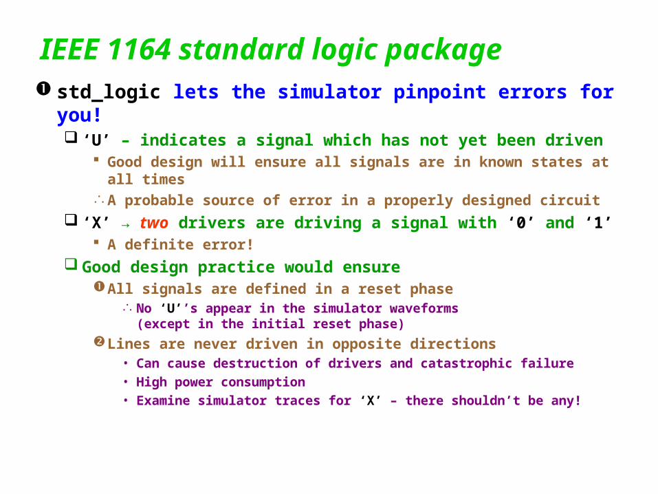
IEEE 1164 standard logic package std_logic lets the simulator pinpoint errors for you!
‘U’ – indicates a signal which has not yet been driven Good design will ensure all signals are in known states at all
timesA probable source of error in a properly designed circuit
‘X’ → two drivers are driving a signal with ‘0’ and ‘1’ A definite error!
Good design practice would ensureAll signals are defined in a reset phase
No ‘U’’s appear in the simulator waveforms (except in the initial reset phase)
Lines are never driven in opposite directions• Can cause destruction of drivers and catastrophic failure• High power consumption• Examine simulator traces for ‘X’ – there shouldn’t be any!

IEEE 1164 standard logic package Bus pull-up and pull-down resistors can be ‘inserted’
Initialise a bus signal to ‘H’ or ‘L’:
‘0’ or ‘1’ from any driver will override the weak ‘H’ or ‘L’:
SIGNAL not_ready : std_logic := ‘H’;
IF seek_finished = ‘1’ THEN not_ready <= ‘0’;END IF;
/ready
10k
VDD
DeviceA DeviceB DeviceC

IEEE 1164 standard logic package Bus drivers can be disconnected
After a bus signal has been driven, it’s necessary to ‘release’ it:
eg once this device has driven not_ready, it should release it so that another device on the bus can assert (drive) it
SIGNAL not_ready : std_logic := ‘H’;
IF seek_finished = ‘1’ THEN not_ready <= ‘0’;END IF;
… -- Perform device actions
-- Now release not_readynot_ready <= ‘Z’;

Standard logic buses
VHDL supports arrays Define an array with
In digital logic design, arrays of std_logic are very common, so a standard type is defined:
std_logic_vector is defined as an unconstrained array:
This means that you can supply the array bounds when youdeclare the array:
TYPE bus8 IS ARRAY(0 TO 7) OF std_logic;data: bus8 := “ZZZZZZZZ”;
data: std_logic_vector(0 TO 7) := “ZZZZZZZZ”;
TYPE std_logic_vector IS ARRAY(integer RANGE <>) OF std_logic;
cmd: std_logic_vector(0 TO 2) := “010”;address: std_logic_vector(0 TO 31);
We will learn more about unconstrained arrays later.Using them allows you to make complex models which youcan use in many situations!

Standard logic buses
VHDL supports arrays Note that arrays can be defined with
ascending or descending indices:
This could be considered convenientorit can lead to confusion!
Careful use of type attributes can make production and maintenance of VHDL models relatively painless!
TYPE bus8 IS ARRAY(0 TO 7) OF std_logic;TYPE rev_bus8 is ARRAY(7 DOWNTO 0) OF std_logic;

Attributes
Attributes of variables and types are the values of properties of types and variables For example, if you have defined an array:
then x’LOW and x’HIGH refer to the bounds of the array: x’LOW is 0 x’HIGH is 31
x : std_logic_vector(0 to 31);

Attributes
Useful attributes are: For all type of variables
LEFT, RIGHT – First or leftmost (last or rightmost) value of a variable
• eg for a : NATURAL RANGE 0 TO 255;a’LEFT is 0 and a’RIGHT is 255
RANGE – eg x’RANGE is 0 to 31• It can be used anywhere a range is needed eg declaring another array of the same size:
followed by
means that if you change the width of x, eg to change to a 64-bit bus, y will automatically follow
There are more attributes which apply only to signals – we will consider them later
x : std_logic_vector(0 TO 31);
y : std_logic_vector(x’RANGE);

This is the first exampleof an algorithmic model.
Note that the ‘code’
is embedded
In a PROCESS block.
Now you can make a module which counts the bits in vectors of any size:
Input can be anystd_logic
vector
Attributes
ENTITY bitcounter IS PORT ( x: IN std_logic_vector; cnt : OUT natural );END bitcounter;
ARCHITECTURE a OF bitcounter IS BEGIN PROCESS VARIABLE count : natural := 0; BEGIN FOR j IN x’RANGE LOOP IF x(j) = ‘1’ THEN count := count + 1; END LOOP; cnt <= count; END PROCESS;END a;
The entity is
The architecture is
RANGE attribute produces the correct loop
indices

VHDL ‘Program’ statements
Process blocks Placed inside architectures Wrappers for program statements Activated by changes in signals in sensitivity lists
--Template for a state machineARCHITECTURE fsm OF x IS BEGIN PROCESS( clk, reset )
IF reset = ‘0’ THEN -- Initialization statements
ELSE
WHEN clk’EVENT AND clk = ‘1’ LOOP
-- Main state machine
END LOOP; END IF; END PROCESS; END fsm;
This template contains many
features of PROCESS blocks,
so we’ll examine it in more detail

VHDL ‘Program’ statements
This example assumes we have a clocked state machine with clk and reset inputs and several other inputs and outputs
The ENTITY is
--Template for a state machineARCHITECTURE fsm OF x IS BEGIN PROCESS( clk, reset )
… END PROCESS;
END fsm;
--State machine entityENTITY x IS PORT)
-- … inputs and outputs
-- needed by this SM clk, reset : IN std_logic );END ENTITY;
clk
reset
inp
uts
ou
tpu
ts

VHDL ‘Program’ statements
Process blocks
--Template for a state machineARCHITECTURE fsm OF x IS BEGIN PROCESS( clk, reset )
IF reset = ‘0’ THEN -- Initialization statements
ELSE
WHEN clk’EVENT AND clk = ‘1’ LOOP
-- Main state machine
END LOOP; END IF; END PROCESS; END fsm;
PROCESS blocks start with PROCESS( sensitivity list ) and end with
END PROCESS;
The PROCESS blocks is entered (activated)on a change in any signal in the sensitivitylist.
In this case, every change of reset or clkwill cause the PROCESS block to be enteredand evaluated.

VHDL ‘Program’ statements
Process blocks
--Template for a state machineARCHITECTURE fsm OF x IS BEGIN PROCESS( clk, reset )
IF reset = ‘0’ THEN -- Initialization statements
ELSE
WHEN clk’EVENT AND clk = ‘1’ LOOP
-- Main state machine
END LOOP; END IF; END PROCESS; END fsm;
Note the END IF pattern –
Most VHDL blocks are like this.
Here is an IF … THEN … ELSE…
END IF;block .

Architectures – Architectural style
ExerciseComplete the structural model for a full adder
by adding the `circuitry’ for the carry out signalWrite a (very short) paragraph describing how
your additions to the full adder model work.If you do this, I will also try to help you improve your technical English by carefully correcting your paragraph. (Hopefully, if we start with some short, simple exercises, you will become much more fluent before the end of semester!)
Bring your exercise to the lecture on Tuesday morning.