am 41 borg – reconfigurable robots - national university of singapore
TRANSCRIPT
AM 41 BORG – RECONFIGURABLE ROBOTS
Submitted by
Tan Han Yong
U006222B11
Department of
Mechanical Engineering
In partial fulfilment of the
requirements for the Degree of
Bachelor of Engineering
National University of Singapore
Session 2003/04
Summary
I
SUMMARY The project objective of Borg – Reconfigurable Robots was to design, build and
test a system of multiple robotic units (Borgs). These Borgs will first be put into
an original configuration, which they must recognize and move together as an
entire unit. The entire unit must also react to a light source and move in that
direction. Then on encountering a narrow channel, the whole unit then has to
reconfigure to form up behind the robot in the through path. They must then
recognize this new formation and move together as one unit through this path.
These required robot behaviors are described in detail in the report.
From the research papers studied during the literature survey, it could be gathered
that the reconfigurable robotic research placed emphasis on the mechanical
attachment between the modular units, some even having Infrared Red sensors to
guide the module-to-module attachments. However, there were no sensors to
detect environmental obstacles, hence the robotic structures lacked the ability to
react to the environmental obstacles and reconfigure. Thus, the challenge of this
project was to develop an algorithm that could allow the entire robotic structure to
reconfigure autonomously when triggered by environmental obstacles. The
approach to the project was segmented into 3 different phases namely design,
build and test phases.
In the design phase, an algorithm was developed for the reconfiguration process.
The approach was novel as it utilized a combination of Light Emitting Diodes
(LEDs) and Light sensors on the Borgs to differentiate their positions in the
structure. This was not attempted in the reconfigurable researches studied for this
Summary
II
project. This was achieved through a unique square design of the Borg, with
identical sides for ease of reconfiguration. Despite the identical faces of the
robots, when 2 Borgs face each other, the LEDs of one would be pointing at the
light sensors of the other. This unique design allows a form of information
transfer through lighting of the LEDs and sensing of light through light sensors.
The building phase saw the fabrication of the Borg from designs drafted using
Solidworks CAD program. The Borg has 3 different layers. The special sensory
layer that houses the LEDs and light and sonar sensors, the Brainstem layer and
the servo layer with a unique wheelbase design developed specifically for this
project. The wheelbase enabled the Borg to move straighter than previous robot
designs by turning 2 wheels with 1 servo. Experiments were then carried out to
calibrate the sensors so as to achieve the desired results in actual hardware testing.
The wireless LAN capabilities of the iPAQ palm pilot provided a platform to
establish a User Datagram Protocol for wireless communication between robotic
units. Much work was also done on Winsock programming specifications.
The reconfiguration algorithm was then tested in phases, from 2 units to an
eventual 4 units. The testing phase started from the second week of December
2003 to the end of March 2004. During this time, the Borgs were given different
initial configurations to test the robustness of the reconfiguration algorithm. The
algorithm held up successfully for different initial configurations of up to 4 Borg
units. The testing phase was concluded with the successful reconfiguration of 4
Borg units through a narrow channel with an example of the reconfiguration
process shown in chapter 4 of this report.
Acknowledgement
III
ACKNOWLEDGEMENT The author wishes to express sincere appreciation for the assistances given by the
following persons in carrying out the work successfully:
Associate Professor Gerard Leng (National University of Singapore), supervisor
of the project, for his patience, advice and guidance in the project.
Mr Cheng Chee Kong (Postgraduate in CoSy Lab) for his assistance and patience
and guidance in the project.
Mr Ng Wee Kiat (Postgraduate in Cosy Lab) for his guidance in this project.
Mr Low Yee Leong (Postgraduate in CoSy Lab) for his guidance in this project.
Toh Kwang Chern and Vincent Tan (fellow undergraduates in CoSy Lab) for their
help and support during the entire course of this project.
The technical staff of the Dynamics Laboratory namely: Ms Amy, Ms Priscilla,
Mr Ahmad and Mr Cheng. For their equipment and technical support in the
project.
Table of Content
IV
TABLE OF CONTENT
SUMMARY ...............................................................................………… I
ACKNOWLEDGEMENTS ..........................................................……... III
TABLE OF CONTENT ..............................................................……... IV
LIST OF FIGURES …………………………………………………... VII
LIST OF TABLES …………………………………………………….. IX
INTRODUCTION ………………………………………………………. 1
LITERATURE SURVEY ……………………………………………... 3
CHAPTER 1: RECONFIGURATION ALGORITHM DESIGN …… 6
1.1 First Configuration Phase …………………………………………. 8
1.1.1 Strength Accounting Phase …………………………………. 8
1.1.2 Borg First Configuration Phase ……………………………... 9
1.2 Navigation Phase …………………………………………………… 10
1.2.1 Target Acquisition Process …………………………………. 11
1.2.2 Formation Control Process …………………………………. 12
1.2.3 Obstruction to Unit Process …………………………………. 14
1.3 Reconfiguration Phase ……………………………………………... 15
1.3.1 Center, Left and Right Accounting Process …………………. 15
1.3.2 The Actual Reconfiguration Process …………………………. 19
1.3.3 New Formation Recognition Process ……………………….. 20
CHAPTER 2: TESTING GROUND SET UP, EXPERIMENTS AND WIRELESS NETWORKING …… 21
2.1 Layout of the Testing Ground ……………………………... 21
2.2 Experiments conducted on Devantech SRF08 Range Finder ……... 21
2.2.1 Sonar Ranging Experiment …………………………………. 21
2.2.2 Light Intensity Experiment …………………………………. 23
Table of Content
V
2.3 Wireless Local Area Network ……………………………………... 24
2.3.1 User Datagram Protocol ……………………………………... 25
2.3.2 Addressing and Internet Protocol …………………………… 25
CHAPTER 3: BORG DESIGN AND ARCHITECTURE …………… 27
3.1 What is a Borg? …………………………………………………... 27
3.2 Borg Architecture and Design ……………………………………. 28
3.2.1 Sensory layer ………………………………………………… 29
3.2.2 Brainstem layer ……………………………………………. 30
3.2.3 Servo layer ………………………………………………… 31
3.2.3.1 Lifting Servo Part ……………………………………... 31
3.2.3.2 Rotation Servo Part …………………………………… 32
3.2.3.3 Wheel Base …………………………………………… 34
3.2.4 Motion of the Servo layer ………………………………….. 35
3.3 Final product: The Borg …………………………………………… 36
CHAPTER 4: ALGORITHM IMPLEMENTATION ……………….. 37
4.1 Reconfiguration Algorithm 1st Phase: 1st Configuration …………… 38
4.2 Reconfiguration Algorithm 2nd Phase: Navigation ……………….. 38
4.3 Reconfiguration Algorithm 2nd Phase: Reconfiguration …………. 39
4.3.1 Center, Left and Right Accounting Process …………………. 40
4.3.2 Actual Reconfiguration Process ……………………………... 40
4.3.3 New Formation Recognition Process ……………………….. 42
CONCLUSION …………………………………………………………. 43
RECOMMENDATION ………………………………………………… 45
REFERENCES …………………………………………………………. 45
APPENDIX A: SONAR SENSOR EXPERIMENT SETUP ……… 47

Table of Content
VI
Appendix B: Experiment Setup for Borg-to-Borg Proximity Range …. 48
Appendix C: Light Intensity Experiment Setup ……... 49
Appendix D: Specifications ………………………………… 50
Appendix E: Component Price List / Expenditure List .… 51
List of Figures
VII
LIST OF FIGURES Figure 1.1: Overview of Problem …………………………………………. 6
Figure 1.2: Flowchart for overall Reconfiguration Algorithm ……………. 7
Figure 1.3: Strength Count Process ………………………………………… 8
Figure 1.4: First Configuration Recognition ………………………………. 9
Figure 1.5: Flowchart Showing Logic Line of Navigation Process ………... 11
Figure 1.6: Formation Control for Borg following ………………………… 13
Figure 1.7: Formation Control for Borg at the sides ……………………….. 14
Figure 1.8: Flowchart showing Logic Line of Center Borg Classification … 15
Figure 1.9: Center Borg identification in Accounting Phase ……………… 16
Figure 1.10: Flowchart Showing Logic Line of Right Borg Classification .. 17
Figure 1.11: Right Borg identification in Accounting Phase ……………... 17
Figure 1.12: Center, Left, Right accounting Process for different configurations …………. 18
Figure 1.13: Right Borgs in Actual Reconfiguration ……………………... 19
Figure 1.14: Left Borgs in place and New Formation is formed ………….. 20
Figure 2.1: Setup of the Testing Ground …………………………………. 21
Figure 3.1: The Acroname PPRK …………………………………………. 27
Figure 3.2: Brainstem GP 1.0 Module ……………………………………... 27
Figure 3.3: Devantech SRF08 Range Finder ………………………………. 28
Figure 3.4: HS-322 HD Servo ……………………………………………… 28
Figure 3.5: CAD Drawing of Sonar Layer …………………………………. 29
Figure 3.6: The Sonar Layer ……………………………………………….. 30
Figure 3.7: Sonar Sensor and LEDs ……………………………………..… 30
Figure 3.8: Light Sensor and LED placement ……………………………... 30
Figure 3.9: Brainstem Layer ……………………………………………….. 31
Figure 3.10: CAD Drawing of Lifting Servo Layer ……………………….. 31
List of Figures
VIII
Figure 3.11: Lifting Servo Part …………………………………………… 32
Figure 3.12: Ball Caster …………………………………………………… 32
Figure 3.13: CAD Drawing of Rotation Servo Layer ……………………... 33
Figure 3.14: Rotation Servo Part …………………………………………... 33
Figure 3.15: Linkage Mechanism …………………………………………. 33
Figure 3.16: CAD Drawing of Wheelbase …………………………………. 34
Figure 3.17: Wheelbase …………………………………………………….. 34
Figure 3.18: Actuation Sequence of Change of Direction ………………... 35
Figure 3.19: Final Borg Design …………………………………………….. 36
Figure 3.20: Final Borg Design in CAD Drawing …………………………. 36
Figure 4.1: First Configuration Recognition ………………………………. 37
Figure 4.2: Target Acquisition, Formation Control and Obstruction to Unit . 38
Figure 4.3: Center, Left, Right Accounting Process ……………………….. 40
Figure 4.4: Actual Reconfiguration Process ……………………………... 41
Figure 4.5: Moving Together in New Formation …………………………... 42
List of Tables
IX
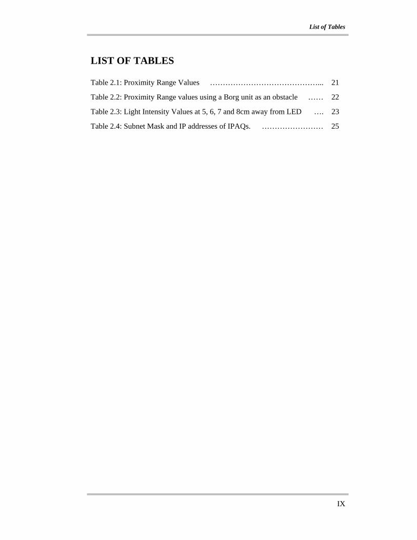
LIST OF TABLES Table 2.1: Proximity Range Values ……………………………………... 21
Table 2.2: Proximity Range values using a Borg unit as an obstacle …… 22
Table 2.3: Light Intensity Values at 5, 6, 7 and 8cm away from LED …. 23
Table 2.4: Subnet Mask and IP addresses of IPAQs. …………………… 25
Introduction
1
INTRODUCTION
Objective
The aim of this project is to have multiple simple robotic units to move together in
a given formation. On acquiring a target, which is a light source, the entire unit
will move towards the target. They will then be required to reconfigure to a new
formation that will enable them to move across a channel that is the width of one
robotic unit.
The Problem
Firstly, the multiple robotic units (Borgs) have to move together as a group. In
doing so, the Borgs must have a formation control algorithm that will keep each
other close in formation. This cannot be achieved unless the Borgs are aware of
whether there are Borgs beside itself. Hence, there has to be a process that will
determine the initial formation that the Borgs are in before they can proceed to
move off as an entire unit. Once moving in formation as a unit, they are required
to acquire the target, which is a light source. Once the target has been acquired,
the entire unit will change the direction of travel and move towards the target.
This change in direction of travel has to be communicated to all the Borgs, by the
Borg(s) that detected the light source and hence, a form of wireless
communication between them has to be established.
The unit will then encounter a narrow channel that is the width of 1 Borg. At this
point, the entire unit will have to stop despite the fact that some of the individual
Borg units are not obstructed (the Borg in the through path). Hence, a message has

Introduction
2
to be sent to the entire unit again to make all the Borgs stop together, further
emphasizing the need for wireless communication. The entire unit must then
reconfigure themselves and form up behind the Borg that is in the through path. In
doing so, the entire unit must be able to differentiate between the Borg in the
through path, and which Borgs are to the right and left of the path. Once that is
accomplished, the Borgs on the left and right will have to move behind the center
Borg to form up the line. On forming the line, the entire Borg unit will have to
undergo another process similar to the initial configuration recognition. The Borgs
will have to once again be aware of the new formation that they are in before they
can move off as an entire unit across the narrow channel.
Scope
This report documents the work that is performed on the project. . The first
chapter describes in detail the thought process of the reconfiguration algorithm.
Chapter 2 will describe the setup of the testing ground, the wireless
communication protocol employed and the experiments conducted to determine
the characteristics of the various sensors followed by chapter which looks into the
Borg design and architecture, the sensors used and components from the
Acroname Palm Pilot Robot Kit that are used in the Borg design. Chapter 4 will
then show the actual implementation of the reconfiguration algorithm on
hardware. Finally, the report is concluded and recommendations made for future
work on the project. A list of references and appendixes will be included at the
end. Next, the work on reconfigurable robots done by other researchers will be
discussed.

Literature Survey
3
LITERATURE SURVEY
The concept of reconfigurable robots has gained popularity over the last few years
and much research has gone into the investigation of the physical aspect of
reconfiguring robots. Most research on reconfigurable robots places emphasis on
the individual robotic modules that can be manually put together to form a larger
unit of a different structure. Mark Yim et al. [1] developed his Modular
reconfigurable robots called the Polybot, which is made from multiple robotic
modules. The multiple modules can be put together to form structures like a snake
like structure or a hexapod structure. Andres Castano et al. [2] built a similar
robotic module called the Conro (CONfigurable RObot), which attempts similar
functions as the polybot from Yim et al. [1]. Andres Castano et al. [2] however
explored the possibility of having a CMOS digital camera to be incorporated onto
each individual robotic module as another sensor or as an alternate means of
control. Kasper Stoy et al. [3] worked more on the formulation of the locomotion
control of the different structures that the Conro robots could form.
Most of the research done is mainly on the hardware of the individual robotic
modules, which differs from the main aim of this project. The robotic units
presented in [2] have 2 servos, one for yaw and the other for pitch and IR sensors
mounted on the connector plates on the 2 extreme ends. One end has connecting
pins and the other end has sockets that fit the pins. This is to enable the docking of
2 robotic modules. However, the robots have to be manually reconfigured to
another shape and have no interaction with the environment to actuate the change
in configuration. This is similar to the robot that is being developed in [1]. The

Literature Survey
4
robotic modules in [1] have a similar design when compared to the Conro robots.
However, the polybots do have a distinct difference as they do have the ability to
self reconfigure and form different structures automatically. This seems to be
similar to what this project sets out to achieve, but the polybots in [1] cannot
initiate the change of structure autonomously from environmental factors, which
is the main objective of this project.
The need for an environmental trigger factor for reconfiguration and autonomous
reconfiguration requires that the robots communicate with one another and pass
on the information that there is obstruction to the entire unit. There is not much
literature on this aspect considering that reconfigurable robot research focuses on
the individual modules and their physical movement as a unit. However, there is
much to learn from research on cooperative systems between multiple robotic
units. One such literature is “Robot Teams”, Tucker Balch and Lynne E. Paker
[4]. The concept of a unit of multiple robotic modules reacting to environmental
factors is similar to that mentioned in [4] on multiagent and multirobot systems. In
[4], there are 4 classifications of multiagent systems, Homogenous
Communicating, Homogenous non-Communicating, Heterogeneous
Communicating and Heterogeneous non-Communicating, of which the
Heterogeneous communicating systems was particular applicable. In that concept,
the communicating agents are different from one another, in terms of different
goals and actions. Thus, a same message sent to all of them could trigger off
different process at different times. This is very similar to that required by a
reconfigurable system where by the positions of the individual units differentiate

Literature Survey
5
them from each other despite the otherwise identical physical aspects. In [6],
studies were done into coordination and collaboration between wasps, which help
them to build and configure structures and make them a coherent lattice for
movement. This gave insight into how collaboration could be applied on the
reconfigurable system.
Since most of the research on reconfigurable systems is concentrated on the
hardware aspect of the individual module, there is room for development of a
reconfigurable system that can make use of environmental factors to act as a
trigger for the autonomous reconfiguration process.
Chapter 1: Reconfiguration Algorithm Design
6
CHAPTER 1: RECONFIGURATION ALGORITHM DESIGN
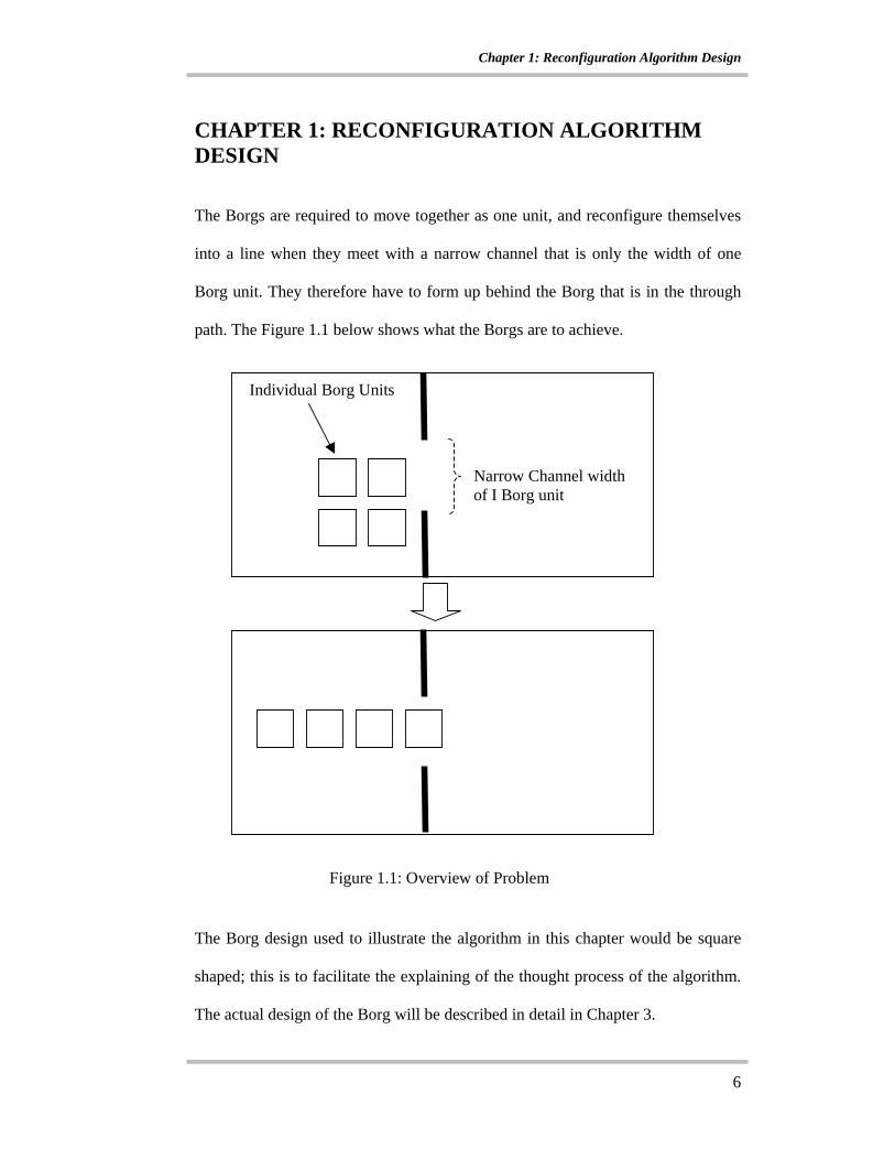
The Borgs are required to move together as one unit, and reconfigure themselves
into a line when they meet with a narrow channel that is only the width of one
Borg unit. They therefore have to form up behind the Borg that is in the through
path. The Figure 1.1 below shows what the Borgs are to achieve.
The Borg design used to illustrate the algorithm in this chapter would be square
shaped; this is to facilitate the explaining of the thought process of the algorithm.
The actual design of the Borg will be described in detail in Chapter 3.
Figure 1.1: Overview of Problem
Individual Borg Units
Narrow Channel width of I Borg unit
Chapter 1: Reconfiguration Algorithm Design
7
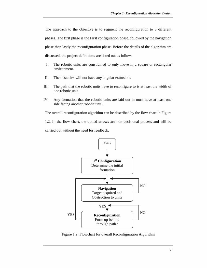
The approach to the objective is to segment the reconfiguration to 3 different
phases. The first phase is the First configuration phase, followed by the navigation
phase then lastly the reconfiguration phase. Before the details of the algorithm are
discussed, the project definitions are listed out as follows:
I. The robotic units are constrained to only move in a square or rectangular environment.
II. The obstacles will not have any angular extrusions
III. The path that the robotic units have to reconfigure to is at least the width of one robotic unit.
IV. Any formation that the robotic units are laid out in must have at least one
side facing another robotic unit.
The overall reconfiguration algorithm can be described by the flow chart in Figure
1.2. In the flow chart, the dotted arrows are non-decisional process and will be
carried out without the need for feedback.
Figure 1.2: Flowchart for overall Reconfiguration Algorithm
NO
YES
NOYES
1st Configuration Determine the initial
formation
Navigation Target acquired and Obstruction to unit?
Reconfiguration Form up behind through path?
Start

Chapter 1: Reconfiguration Algorithm Design
8
1.1 First Configuration Phase
In this phase, the program will first account for the total strength of the Borgs in
action. It will then establish the initial Borg formation.
1.1.1 Strength Accounting Phase
The first process here is the Strength Count. This process will establish the total
number of Borgs in action. As shown in Figure 1.3, the controller will broadcast
an initiating message to all the Borgs that are in action. This message initiates the
strength count process for the Borgs.
On receiving the Strength Count message, the Borgs will each broadcast a
strength message; all the Borgs in action will receive this message.
By counting the total number of messages that each Borg receives, the total
strength of the Borgs will be 1 more of that number. Employing this method, the
program does not require manual input of total strength of Borgs in action.
Strength Message
2
1
Initiating Strength Count
Borg 2
Borg 1
Controller
2
1
Figure 1.3: Strength Count Process

Chapter 1: Reconfiguration Algorithm Design
9
1.1.2 Borg First Configuration Phase
The next process of the First configuration is to establish the first Borg formation,
which is the shape that the Borgs are initially put into and supposed to maintain. If
each Borg were to be square shaped, then by mounting light sensors and Light
Emitting Diodes (LEDs) on all its corners, the first configuration that they are put
in could be determined by firstly having all the Borgs switch on all the LEDs on
all its sides, and then by making use of the light sensors to sense for any light
source on any of it’s sides. Hence, any light detected by the Borgs on any of it’s
side would mean that that side has another Borg beside it. See Figure 1.4.
In the case shown in Figure 1.4, Borg 2 in the green circle senses light coming
from 2 of it’s sides due to the LEDs of Borg 1 and Borg 4 thus it will be aware
that it has 2 Borgs beside it.This information will be stored and used later in the
navigation phase and the reconfiguration process. Once this information is
obtained for all the Borgs, the process will switch off all the LEDs and then
proceed to the navigation phase of the reconfiguration.
- Switched on LEDS - Sonar/Photo sensors - Photo sensors that detected light source
Borg 1
Borg 3
Borg 4
Borg 2
Figure 1.4: First Configuration Recognition

Chapter 1: Reconfiguration Algorithm Design
10
1.2 Navigation Phase
In this phase, the Borgs will then move together as a unit. The navigation phase of
the process has 3 key process working in the background as the unit moves. They
are as follows.
I. Target Acquisition Process:
The Borgs must activate the photo sensors in all directions and sense for
any light source at this point. The light source is the target and the Borgs
will then move towards the target as a unit.
II. Formation Control Process:
In moving as a unit, the borgs must stay together, not necessarily keeping
the original configuration, but at least not allow any one Borg to be left
way out of the formation.
III. Obstruction to Unit Process:
The Borgs will have to stop the moment any one of the Borgs encounter an
obstacle to it’s path. If at this stage, the target is acquired, this will then
trigger the reconfiguration phase.
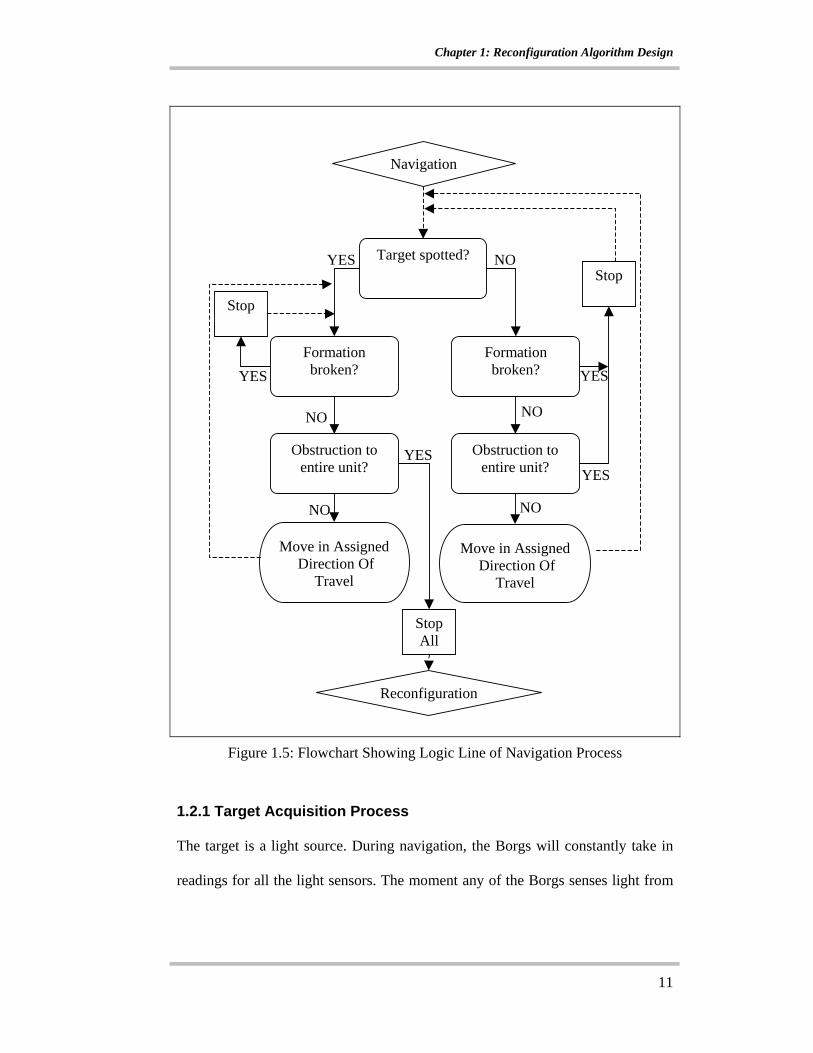
The following Figure 1.5 shows a flowchart that describes the logic line of the
navigation phase of the program.
Chapter 1: Reconfiguration Algorithm Design
11
Figure 1.5: Flowchart Showing Logic Line of Navigation Process
1.2.1 Target Acquisition Process
The target is a light source. During navigation, the Borgs will constantly take in
readings for all the light sensors. The moment any of the Borgs senses light from
Formation broken?
Target spotted?
Obstruction to entire unit?
Stop NO
Obstruction to entire unit?
Reconfiguration
Navigation
NO
NO NO
NO
YESFormation broken?
Move in Assigned Direction Of
Travel
YES
YES
YES
StopAll
Stop
YES
Move in Assigned Direction Of
Travel
Chapter 1: Reconfiguration Algorithm Design
12
any direction, the entire unit will then change the direction of travel to that
direction. Hence, the target is acquired once light is sensed in any direction.
The Borgs will only reconfigure if target is acquired. If no target is acquired, and
the Borg unit meets with an obstacle, it will not reconfigure itself, it will only stop
and wait to acquire the target.
1.2.2 Formation Control Process
To move as a unit, the borgs must try to stay close to one another during
navigation. The information as to which Borgs is beside another has been
determined during the first configuration phase. The information is different for
each Borg and is stored locally in each Borg.
With reference to Figure 1.6, the Borgs are traveling in the direction as assigned.
Borg 1 has the information that Borg 2 is behind it relative to the direction of
travel. It would then move together as seen in part 1 of the diagram. The rear
sonar sensors of Borg 1 would be activated to take readings of the distance
between itself and Borg 2. Once the distance exceeds the assigned proximity
range value, Borg 1 would stop moving as shown in the transition from part 2 to
part 3 of the diagram. This is so that Borg 2 would be able to catch up with Borg 1
before it falls out of formation; hence Borg 1 is required to stop. Once the distance
Borg 1 and Borg 2 is within range, Borg 1 would start moving again.

Chapter 1: Reconfiguration Algorithm Design
13
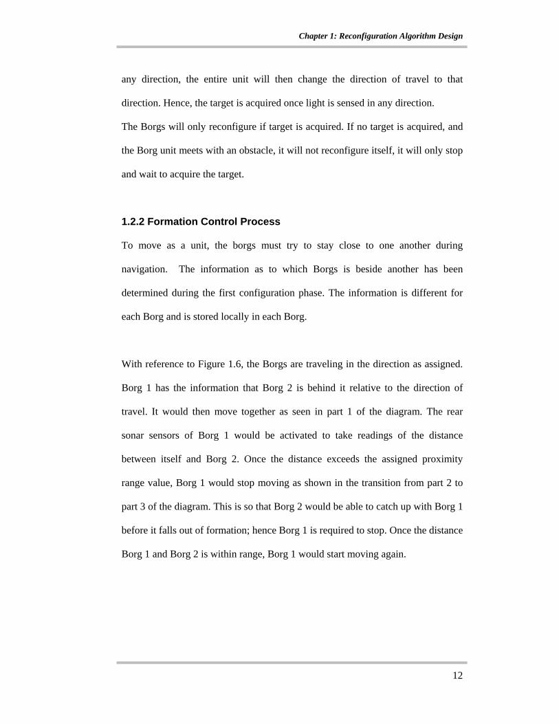
This formation control algorithm is also applied to formations that have Borgs
beside one another. With reference to Figure 1.7, Borg 1 and 2 are to travel in the
direction as shown. Borg 1 and 2 both have information that they are beside one
another. As seen in part 2 of the diagram, the moment Borg 2 moves ahead of
Borg 1 and hence falls out of formation, the corner sonar sensor of Borg 2 will
give a reading that exceeds the proximity range. This would cause Borg 2 to stop
and wait for Borg 1 to catch up. Once Borg 1 catches up, Borg 2 will resume its
movement in the original direction.
- Sonar readings in Proximity range
Borg 2
Borg 1
Direction of Travel
Borg 2
Borg 1
Borg 2
Borg 1
Borg 2
Borg 1
1.
2.
3.
4.
- Sonar readings exceeding Proximity range
Figure 1.6: Formation Control for Borg following
Chapter 1: Reconfiguration Algorithm Design
14
1.2.3 Obstruction to Unit Process
The obstruction to unit process will trigger the start of the reconfiguration process
and stop the navigation process. This will only occur when the entire Borg unit
meets with any obstacles in the direction of travel and target has been acquired.
Generally, the setup of the testing area will have a channel the width of one Borg
unit. Hence, the other Borg units when moving together as one, and after
acquiring the target, will encounter a wall and hence an obstacle and only one
Borg unit will sense the channel. All other Borgs will thus have to form up behind
the Borg that senses the channel.
Direction of Travel
Borg 2
Borg 1
Borg 2
Borg 1 Borg 2
Borg 1
1. 2. 3.
Direction of Travel
Direction of Travel
- Sonar readings in Proximity range
- Sonar readings exceeding Proximity range
Figure 1.7: Formation Control for Borg at the sides
Chapter 1: Reconfiguration Algorithm Design
15
1.3 Reconfiguration Phase
At this point, the Borg unit as a whole would have acquired a target and met with
an obstacle to the target, this would trigger the reconfiguration phase of the
program. The reconfiguration phase is broken down to a 3 different process:
I. The Center, Left and Right Accounting Process
II. The Actual Reconfiguration Process
III. The New Formation Recognition Process
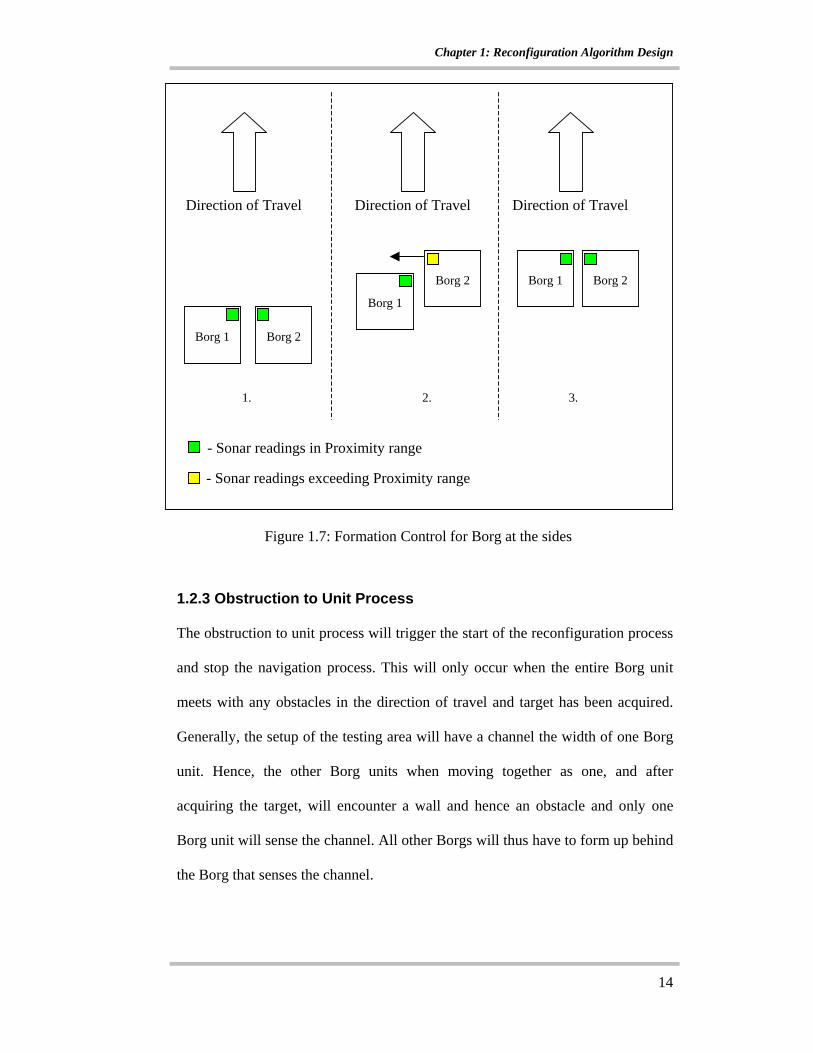
1.3.1 Center, Left and Right Accounting Process
In this process, the entire unit first starts to differentiate which Borgs are the
center Borgs that represent the through path that all the other Borgs have to form
up behind. The following flowchart will show the logic process.
Reconfig
NO Obstruction in Direction of travel
OR light detected in front?
Center Borg (Borg in Through path)
On rear LEDS CENTER Phase
Time out?
NO NO
YES
YES
Accounting Phase
Proceed to the right phase
Figure 1.8: Flowchart showing Logic Line of Center Borg Classification
Chapter 1: Reconfiguration Algorithm Design
16
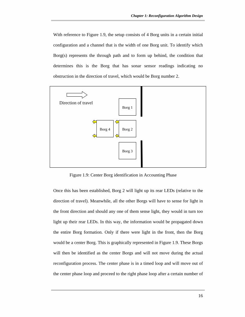
With reference to Figure 1.9, the setup consists of 4 Borg units in a certain initial
configuration and a channel that is the width of one Borg unit. To identify which
Borg(s) represents the through path and to form up behind, the condition that
determines this is the Borg that has sonar sensor readings indicating no
obstruction in the direction of travel, which would be Borg number 2.
Once this has been established, Borg 2 will light up its rear LEDs (relative to the
direction of travel). Meanwhile, all the other Borgs will have to sense for light in
the front direction and should any one of them sense light, they would in turn too
light up their rear LEDs. In this way, the information would be propagated down
the entire Borg formation. Only if there were light in the front, then the Borg
would be a center Borg. This is graphically represented in Figure 1.9. These Borgs
will then be identified as the center Borgs and will not move during the actual
reconfiguration process. The center phase is in a timed loop and will move out of
the center phase loop and proceed to the right phase loop after a certain number of
Direction of travel Borg 1
Borg 2
Borg 4
Borg 3
Figure 1.9: Center Borg identification in Accounting Phase
Chapter 1: Reconfiguration Algorithm Design
17
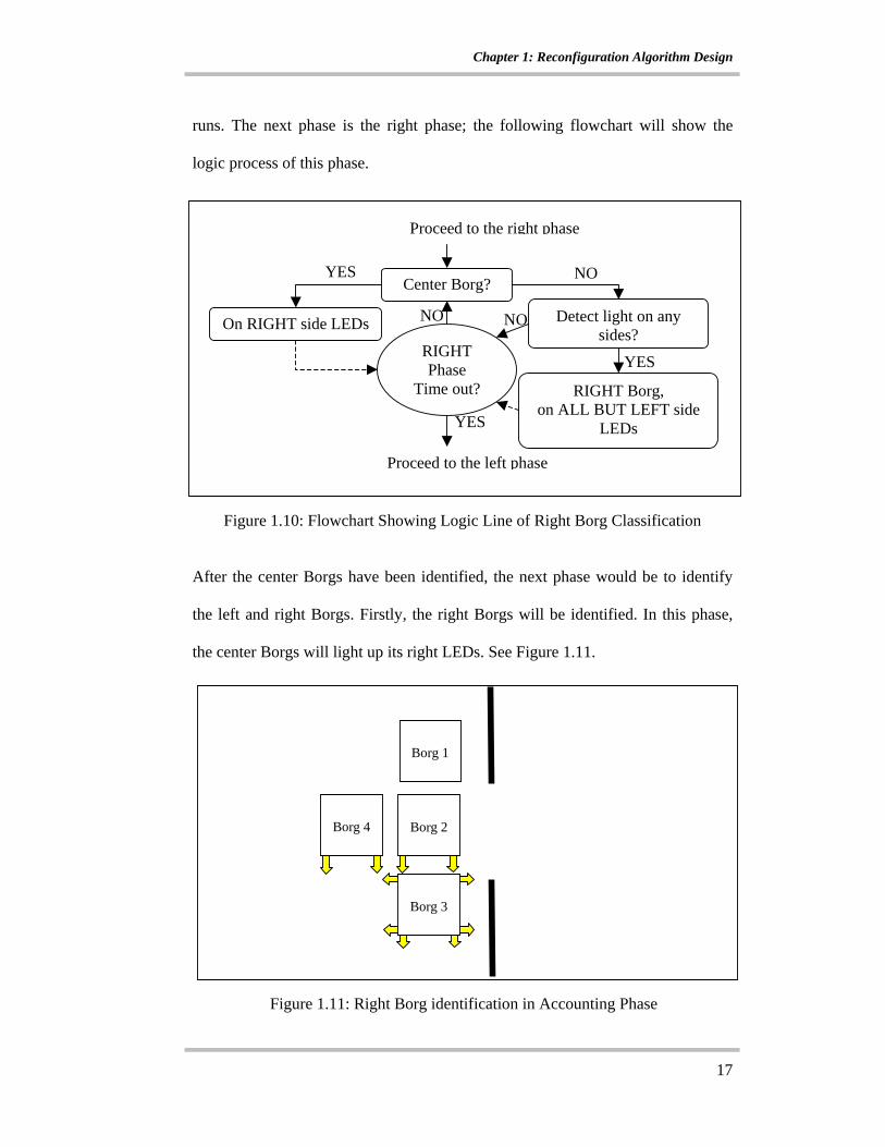
runs. The next phase is the right phase; the following flowchart will show the
logic process of this phase.
After the center Borgs have been identified, the next phase would be to identify
the left and right Borgs. Firstly, the right Borgs will be identified. In this phase,
the center Borgs will light up its right LEDs. See Figure 1.11.
Borg 1
Borg 2
Borg 4
Borg 3
Figure 1.11: Right Borg identification in Accounting Phase
Figure 1.10: Flowchart Showing Logic Line of Right Borg Classification
Center Borg?
RIGHT Phase
Time out?
On RIGHT side LEDs Detect light on any sides?
RIGHT Borg, on ALL BUT LEFT side
LEDs
NO
NONO
YES
YES
YES
Proceed to the right phase
Proceed to the left phase
Chapter 1: Reconfiguration Algorithm Design
18
The rest of the Borgs that are not center Borgs will be programmed to sense for
light on all its sides. And so since the center Borgs lighted up the right LEDs, any
Borgs that sense light in this phase will be the right Borgs. With reference to
Figure 1.11 above, Borg 3 is the right Borg and lights up all but its left LEDs.
Once this phase is done and both the right and center Borgs have been
determined, the center Borgs will then switch on their left LEDs while the right
Borgs will switch off all theirs. The left Borgs will then be determined the same
way as the right Borgs.
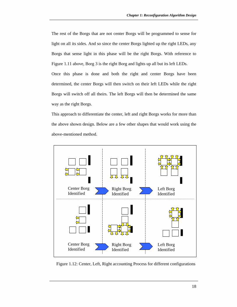
This approach to differentiate the center, left and right Borgs works for more than
the above shown design. Below are a few other shapes that would work using the
above-mentioned method.
Right Borg Identified
Center Borg Identified
Left Borg Identified
Right Borg Identified
Center Borg Identified
Left Borg Identified
Figure 1.12: Center, Left, Right accounting Process for different configurations
Chapter 1: Reconfiguration Algorithm Design
19
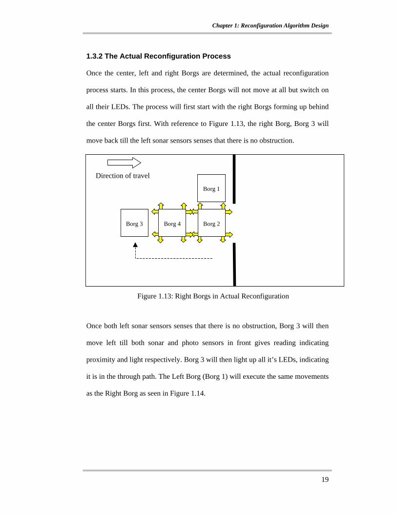
1.3.2 The Actual Reconfiguration Process
Once the center, left and right Borgs are determined, the actual reconfiguration
process starts. In this process, the center Borgs will not move at all but switch on
all their LEDs. The process will first start with the right Borgs forming up behind
the center Borgs first. With reference to Figure 1.13, the right Borg, Borg 3 will
move back till the left sonar sensors senses that there is no obstruction.
Once both left sonar sensors senses that there is no obstruction, Borg 3 will then
move left till both sonar and photo sensors in front gives reading indicating
proximity and light respectively. Borg 3 will then light up all it’s LEDs, indicating
it is in the through path. The Left Borg (Borg 1) will execute the same movements
as the Right Borg as seen in Figure 1.14.
Borg 1
Borg 2
Borg 4
Borg 3
Direction of travel
Figure 1.13: Right Borgs in Actual Reconfiguration

Chapter 1: Reconfiguration Algorithm Design
20
1.3.3 New Formation Recognition Process
Once Borg 1 is in position, a new formation is formed and a process similar to the
first configuration phase is performed at this point. See Figure 1.14.
The new formation is recognized and the Borgs will then switch off all its LEDs.
At this point, the Reconfiguration Process is complete, the program will then
switch back into the Navigation Phase and proceed to move through the channel
in a line and still keeping the New Formation.
Borg 2
Borg 4
Direction of travel
Borg 3
Borg 1
Figure 1.14: Left Borgs in place and New Formation is formed
Chapter 2:Testing Ground Set Up, Experiments and Wireless Networking
21
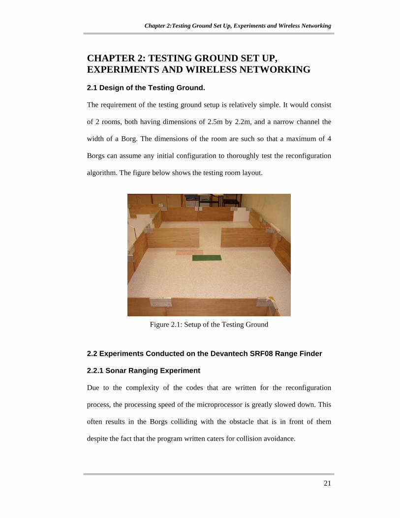
CHAPTER 2: TESTING GROUND SET UP, EXPERIMENTS AND WIRELESS NETWORKING 2.1 Design of the Testing Ground.
The requirement of the testing ground setup is relatively simple. It would consist
of 2 rooms, both having dimensions of 2.5m by 2.2m, and a narrow channel the
width of a Borg. The dimensions of the room are such so that a maximum of 4
Borgs can assume any initial configuration to thoroughly test the reconfiguration
algorithm. The figure below shows the testing room layout.
Figure 2.1: Setup of the Testing Ground
2.2 Experiments Conducted on the Devantech SRF08 Range Finder 2.2.1 Sonar Ranging Experiment
Due to the complexity of the codes that are written for the reconfiguration
process, the processing speed of the microprocessor is greatly slowed down. This
often results in the Borgs colliding with the obstacle that is in front of them
despite the fact that the program written caters for collision avoidance.
Chapter 2:Testing Ground Set Up, Experiments and Wireless Networking
22
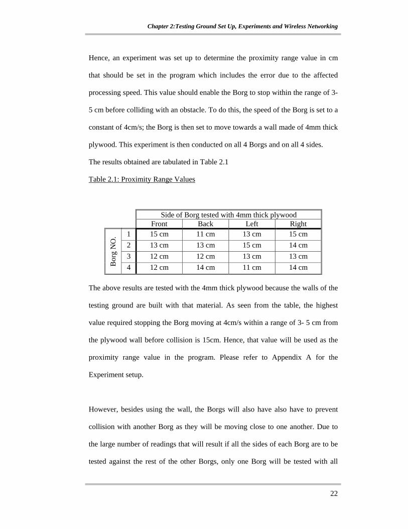
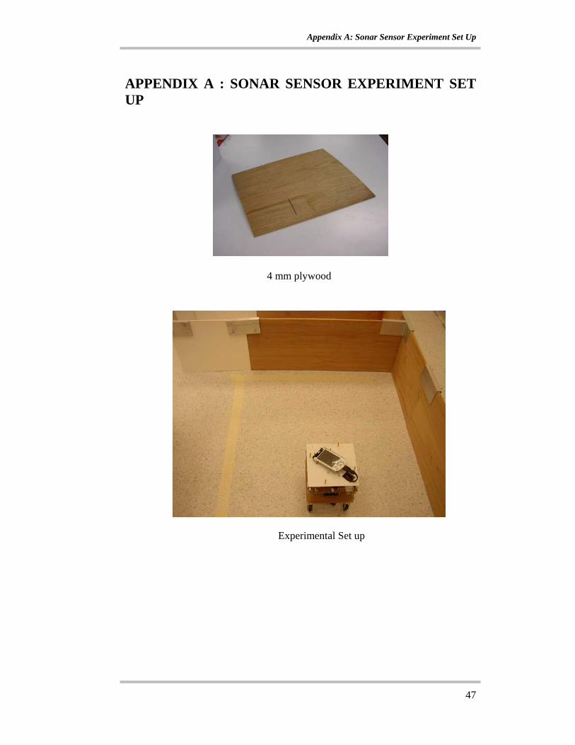
Hence, an experiment was set up to determine the proximity range value in cm
that should be set in the program which includes the error due to the affected
processing speed. This value should enable the Borg to stop within the range of 3-
5 cm before colliding with an obstacle. To do this, the speed of the Borg is set to a
constant of 4cm/s; the Borg is then set to move towards a wall made of 4mm thick
plywood. This experiment is then conducted on all 4 Borgs and on all 4 sides.
The results obtained are tabulated in Table 2.1
Table 2.1: Proximity Range Values
Side of Borg tested with 4mm thick plywood Front Back Left Right
1 15 cm 11 cm 13 cm 15 cm 2 13 cm 13 cm 15 cm 14 cm 3 12 cm 12 cm 13 cm 13 cm
Bor
g N
O.
4 12 cm 14 cm 11 cm 14 cm The above results are tested with the 4mm thick plywood because the walls of the
testing ground are built with that material. As seen from the table, the highest
value required stopping the Borg moving at 4cm/s within a range of 3- 5 cm from
the plywood wall before collision is 15cm. Hence, that value will be used as the
proximity range value in the program. Please refer to Appendix A for the
Experiment setup.
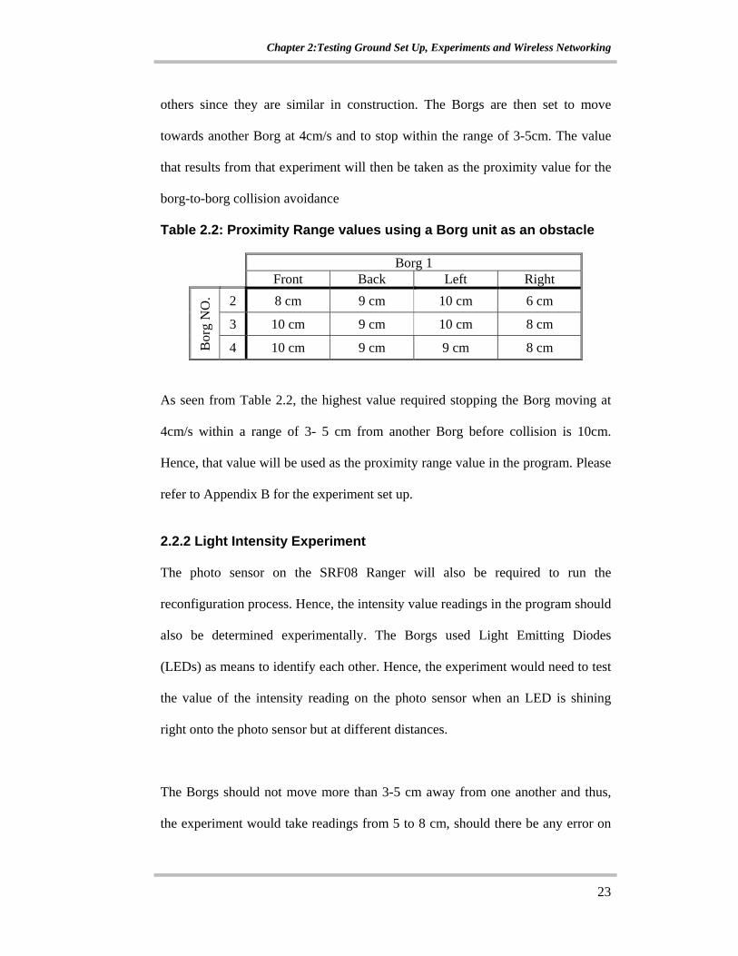
However, besides using the wall, the Borgs will also have also have to prevent
collision with another Borg as they will be moving close to one another. Due to
the large number of readings that will result if all the sides of each Borg are to be
tested against the rest of the other Borgs, only one Borg will be tested with all
Chapter 2:Testing Ground Set Up, Experiments and Wireless Networking
23
others since they are similar in construction. The Borgs are then set to move
towards another Borg at 4cm/s and to stop within the range of 3-5cm. The value
that results from that experiment will then be taken as the proximity value for the
borg-to-borg collision avoidance
Table 2.2: Proximity Range values using a Borg unit as an obstacle
Borg 1 Front Back Left Right
2 8 cm 9 cm 10 cm 6 cm
3 10 cm 9 cm 10 cm 8 cm
Bor
g N
O.
4 10 cm 9 cm 9 cm 8 cm
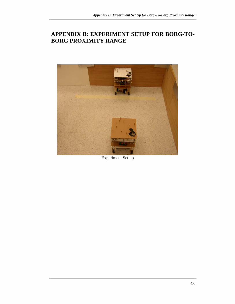
As seen from Table 2.2, the highest value required stopping the Borg moving at
4cm/s within a range of 3- 5 cm from another Borg before collision is 10cm.
Hence, that value will be used as the proximity range value in the program. Please
refer to Appendix B for the experiment set up.
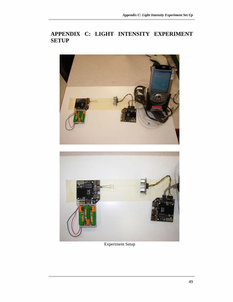
2.2.2 Light Intensity Experiment
The photo sensor on the SRF08 Ranger will also be required to run the
reconfiguration process. Hence, the intensity value readings in the program should
also be determined experimentally. The Borgs used Light Emitting Diodes
(LEDs) as means to identify each other. Hence, the experiment would need to test
the value of the intensity reading on the photo sensor when an LED is shining
right onto the photo sensor but at different distances.
The Borgs should not move more than 3-5 cm away from one another and thus,
the experiment would take readings from 5 to 8 cm, should there be any error on

Chapter 2:Testing Ground Set Up, Experiments and Wireless Networking
24
the keeping close algorithm and the Borgs end up more than 5 cm from one
another. The results are shown in Table 2.3
Table 2.3: Light Intensity Values at 5, 6, 7 and 8cm away from LED
Distance LEDs are away from the sensor / cm 5 6 7 8
1 80 68 46 32 2 81 66 50 38 3 79 65 48 38 4 79 65 48 36 5 83 66 50 34 6 80 63 52 31 7 80 68 50 33 8 85 66 51 34 9 80 71 49 39 10 81 72 43 31 11 81 69 43 33 12 84 71 52 32 13 80 69 50 34 14 80 68 51 32 15 83 63 50 38
Phot
o Se
nsor
NO
.
16 79 63 49 39 16 Photo sensors are tested and there is some consistency in the values, hence,
only 16 sensors are tested in the experiment. As can be seen from the table, at
8cm, the lowest reading value is 31. Hence, the light reading minimum is 31 and
hence, this value would be used in the reconfiguration process. Please refer to
Appendix C for the experiment setup.
2.3 Wireless Local Area Network
The Borgs need to communicate between each other, hence there has to be a form
of networking between them. The IPAQ that is used to link up with the Brainstem
GP 1.0 has an internal Wireless Local Area Network (LAN) card and could be
utilized to send messages between the Borgs. Winsock specification is used for
Chapter 2:Testing Ground Set Up, Experiments and Wireless Networking
25
the networking programming codes. Winsock is chosen mainly because it is
WinCE compatible, which is essential as the IPAQ Operating System runs on the
WinCE platform. Also, the necessary libraries and headers can be compiled in
C++ Language and could be compiled together with the main program code in
Embedded Microsoft Visual C++.
2.3.1 User Datagram Protocol (UDP)
The protocol used in the wireless LAN network setup is the User Datagram
Protocol (UDP). This protocol uses similar information transport methods as the
Transmission Control Protocol (TCP); however, the difference here is that UDP
does not require a server client relationship in the network. Hence, any message
sent out by any one user goes out to all the other users including itself. This
protocol is particularly simple to implement, as there is no need to have an
external router to act as a server.
2.3.2 Addressing and Internet Protocol
Most computers can be assigned an Internet Protocol address (IP address). This
address is represented by a 32-bit quantity. Hence, when a user wants to
communicate with another user on a network, the most important information is
the IP address of the other user. The IPAQ palm pilot that is being used in this
project could also be assigned an IP address, enabling them to send messages
across to one another. As the IPAQs user UDP protocol, there is no need to setup
a server/client relationship. There is however a need to identify the network that
all the users are on, this requires another quantity called the subnet mask. This is a
similar 32-bit quantity as the IP; just that it is solely for network identification.
Chapter 2:Testing Ground Set Up, Experiments and Wireless Networking
26
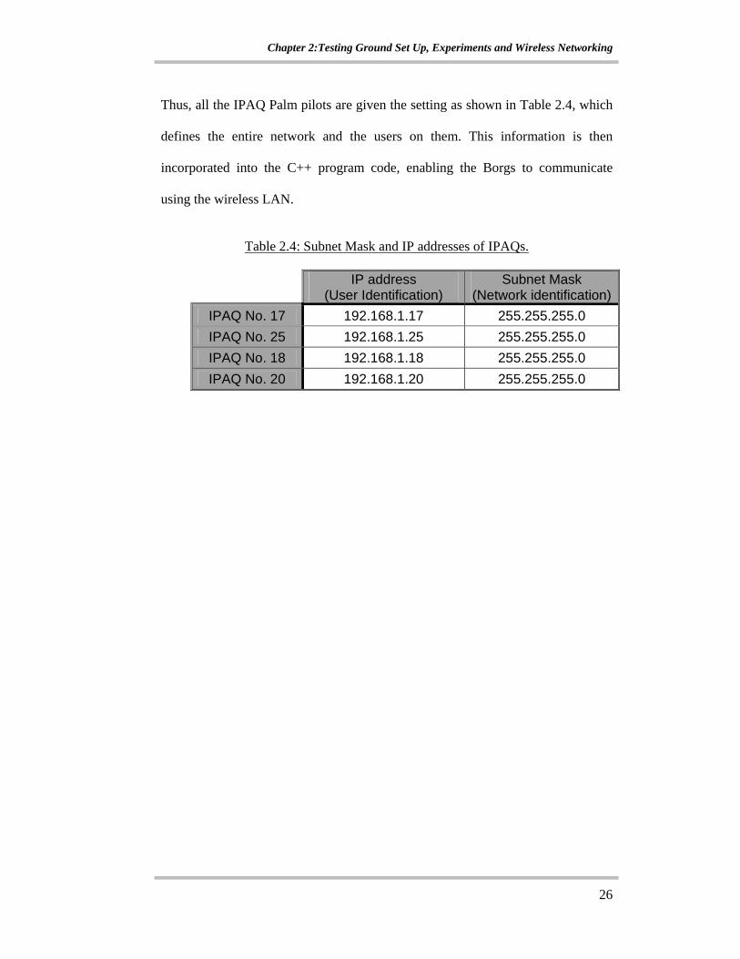
Thus, all the IPAQ Palm pilots are given the setting as shown in Table 2.4, which
defines the entire network and the users on them. This information is then
incorporated into the C++ program code, enabling the Borgs to communicate
using the wireless LAN.
Table 2.4: Subnet Mask and IP addresses of IPAQs.
IP address (User Identification)
Subnet Mask (Network identification)
IPAQ No. 17 192.168.1.17 255.255.255.0 IPAQ No. 25 192.168.1.25 255.255.255.0 IPAQ No. 18 192.168.1.18 255.255.255.0 IPAQ No. 20 192.168.1.20 255.255.255.0
Chapter 3:Borg Design and Architecture
27
CHAPTER 3: BORG DESIGN AND ARCHITECTURE 3.1 What is a Borg?
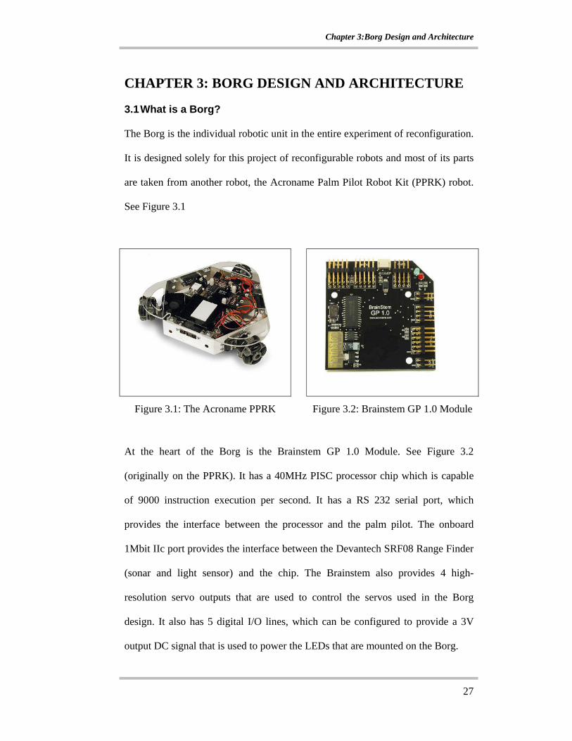
The Borg is the individual robotic unit in the entire experiment of reconfiguration.
It is designed solely for this project of reconfigurable robots and most of its parts
are taken from another robot, the Acroname Palm Pilot Robot Kit (PPRK) robot.
See Figure 3.1
Figure 3.1: The Acroname PPRK Figure 3.2: Brainstem GP 1.0 Module
At the heart of the Borg is the Brainstem GP 1.0 Module. See Figure 3.2
(originally on the PPRK). It has a 40MHz PISC processor chip which is capable
of 9000 instruction execution per second. It has a RS 232 serial port, which
provides the interface between the processor and the palm pilot. The onboard
1Mbit IIc port provides the interface between the Devantech SRF08 Range Finder
(sonar and light sensor) and the chip. The Brainstem also provides 4 high-
resolution servo outputs that are used to control the servos used in the Borg
design. It also has 5 digital I/O lines, which can be configured to provide a 3V
output DC signal that is used to power the LEDs that are mounted on the Borg.
Chapter 3:Borg Design and Architecture
28
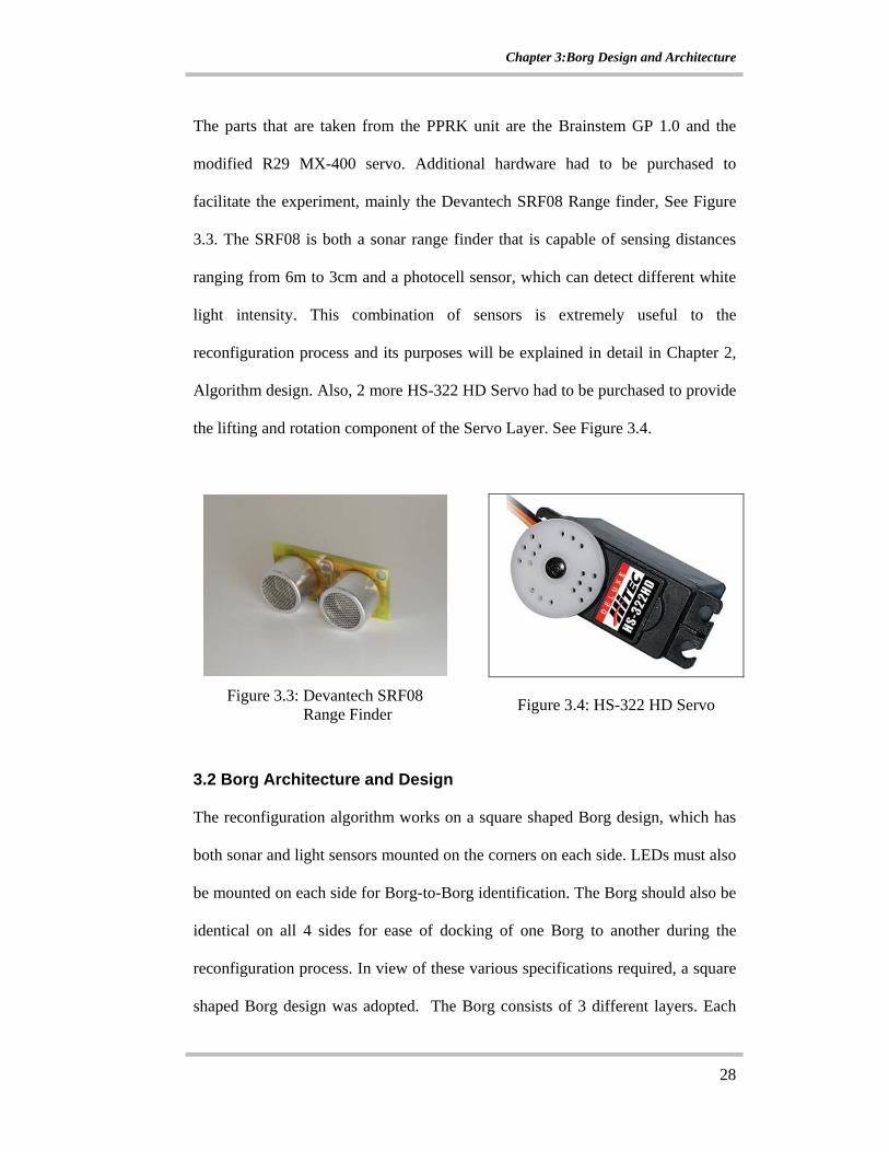
The parts that are taken from the PPRK unit are the Brainstem GP 1.0 and the
modified R29 MX-400 servo. Additional hardware had to be purchased to
facilitate the experiment, mainly the Devantech SRF08 Range finder, See Figure
3.3. The SRF08 is both a sonar range finder that is capable of sensing distances
ranging from 6m to 3cm and a photocell sensor, which can detect different white
light intensity. This combination of sensors is extremely useful to the
reconfiguration process and its purposes will be explained in detail in Chapter 2,
Algorithm design. Also, 2 more HS-322 HD Servo had to be purchased to provide
the lifting and rotation component of the Servo Layer. See Figure 3.4.
Figure 3.3: Devantech SRF08
Range Finder
Figure 3.4: HS-322 HD Servo
3.2 Borg Architecture and Design
The reconfiguration algorithm works on a square shaped Borg design, which has
both sonar and light sensors mounted on the corners on each side. LEDs must also
be mounted on each side for Borg-to-Borg identification. The Borg should also be
identical on all 4 sides for ease of docking of one Borg to another during the
reconfiguration process. In view of these various specifications required, a square
shaped Borg design was adopted. The Borg consists of 3 different layers. Each

Chapter 3:Borg Design and Architecture
29
layer is square in shape hence the entire Borg unit is shaped like a cube. The first
layer is the sensory layer of the Borg, where the sonar and light sensors are
mounted on. Also, there are rows of 7 Light Emitting Diodes (LEDs) mounted
beside each sonar and light sensor. The second layer is the Brainstem layer. This
is the layer where Brainstem GP 1.0 chip is mounted on. The switch and the
batteries can all be found on this layer. The last layer of the Borg unit is the servo
layer. This is the layer that provides the locomotion of the Borg unit. The Borg
designs were drafted out in Solidworks CAD Software before any fabrication took
place.
3.2.1 Sensory Layer
The design of the sensory layer is such that there is symmetry on all sides of the
Borg. By having such a design, the Borgs do not have to rotate its orientation in
order to form up behind another Borg. The Figure 3.5 shows the layout of the
sensory layer in CAD Drawing and Figure 3.6 shows the actual sonar sensor
layer.
Figure 3.5: CAD Drawing of Sonar Layer
Chapter 3:Borg Design and Architecture
30
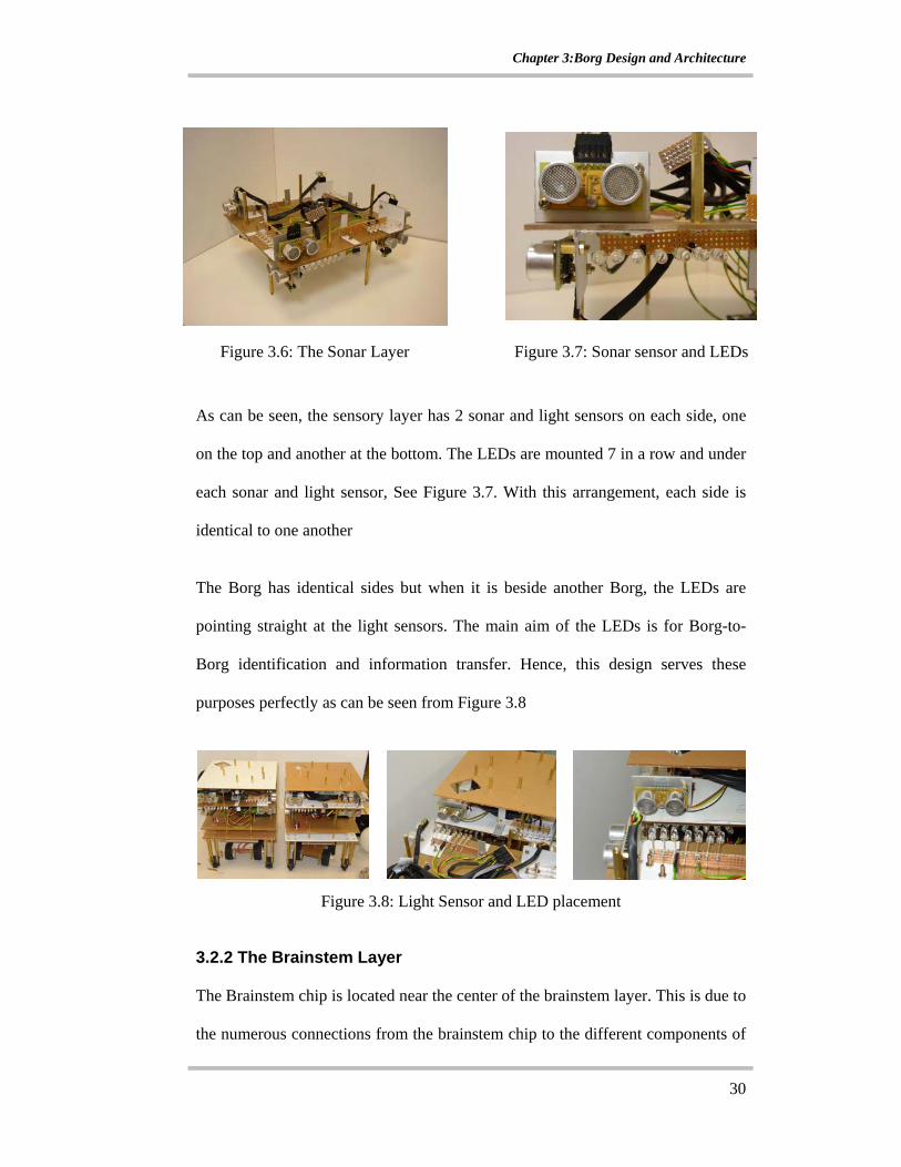
Figure 3.6: The Sonar Layer Figure 3.7: Sonar sensor and LEDs
As can be seen, the sensory layer has 2 sonar and light sensors on each side, one
on the top and another at the bottom. The LEDs are mounted 7 in a row and under
each sonar and light sensor, See Figure 3.7. With this arrangement, each side is
identical to one another
The Borg has identical sides but when it is beside another Borg, the LEDs are
pointing straight at the light sensors. The main aim of the LEDs is for Borg-to-
Borg identification and information transfer. Hence, this design serves these
purposes perfectly as can be seen from Figure 3.8
Figure 3.8: Light Sensor and LED placement
3.2.2 The Brainstem Layer
The Brainstem chip is located near the center of the brainstem layer. This is due to
the numerous connections from the brainstem chip to the different components of
Chapter 3:Borg Design and Architecture
31
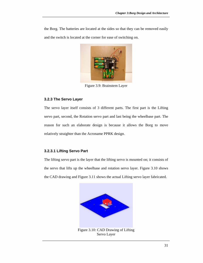
the Borg. The batteries are located at the sides so that they can be removed easily
and the switch is located at the corner for ease of switching on.
Figure 3.9: Brainstem Layer
3.2.3 The Servo Layer
The servo layer itself consists of 3 different parts. The first part is the Lifting
servo part, second, the Rotation servo part and last being the wheelbase part. The
reason for such an elaborate design is because it allows the Borg to move
relatively straighter than the Acroname PPRK design.
3.2.3.1 Lifting Servo Part
The lifting servo part is the layer that the lifting servo is mounted on; it consists of
the servo that lifts up the wheelbase and rotation servo layer. Figure 3.10 shows
the CAD drawing and Figure 3.11 shows the actual Lifting servo layer fabricated.
Figure 3.10: CAD Drawing of Lifting
Servo Layer

Chapter 3:Borg Design and Architecture
32
Figure 3.11: Lifting Servo Part Figure 3.12: Ball Caster
This is also the layer that the ball casters are mounted on. The ball caster consists
of a ball bearing cast at the bottom of the casing, which gives vertical support and
minimal horizontal resistance to dragging See Figure 3.12. When the lifting servo
is activated, the entire locomotion base of the Borg is lifted up and the ball casters
provide the necessary support.
3.2.3.2 Rotation Servo Part
This rotation servo rotates the wheelbase of the Borg to achieve the change of
direction in locomotion of the Borg by turning the entire wheelbase to different
pre-assigned direction. To ensure vertical lifting with minimal side deviation,
there are 4 vertical support pillars on the 4 corners of the rotation servo layer,
which guides the lifting action. See Figure 3.13 for the CAD Drawing and Figure
3.14 for the actual fabricated component.
Chapter 3:Borg Design and Architecture
33
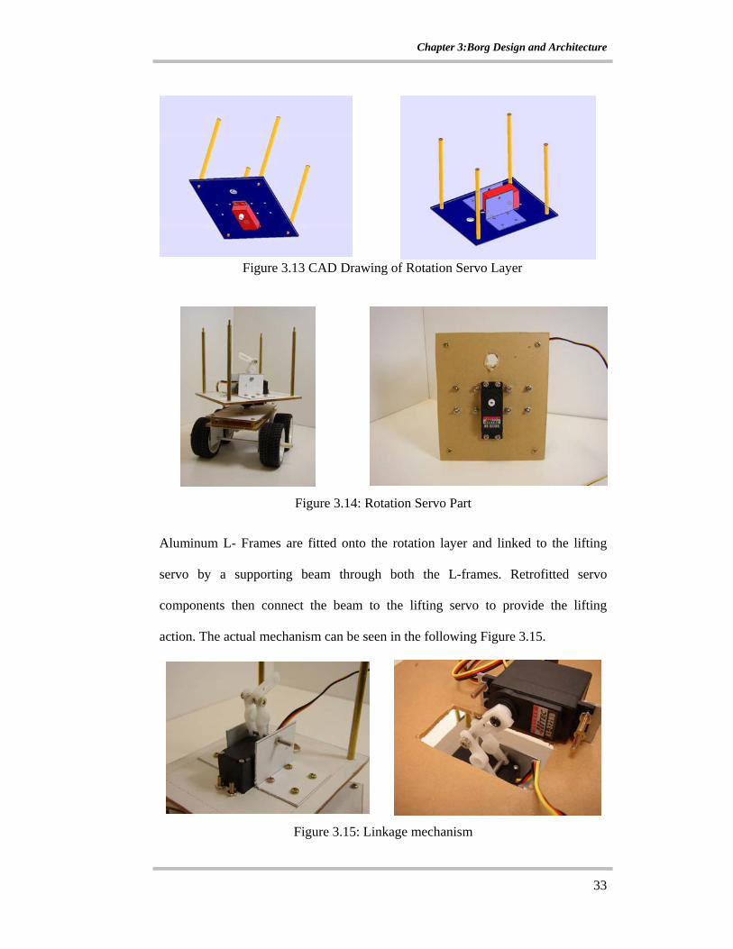
Figure 3.13 CAD Drawing of Rotation Servo Layer
Figure 3.14: Rotation Servo Part
Aluminum L- Frames are fitted onto the rotation layer and linked to the lifting
servo by a supporting beam through both the L-frames. Retrofitted servo
components then connect the beam to the lifting servo to provide the lifting
action. The actual mechanism can be seen in the following Figure 3.15.
Figure 3.15: Linkage mechanism
Chapter 3:Borg Design and Architecture
34
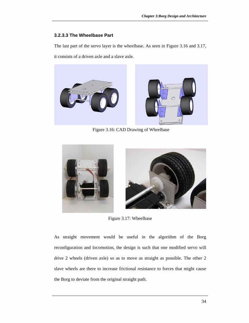
3.2.3.3 The Wheelbase Part
The last part of the servo layer is the wheelbase. As seen in Figure 3.16 and 3.17,
it consists of a driven axle and a slave axle.
Figure 3.16: CAD Drawing of Wheelbase
Figure 3.17: Wheelbase
As straight movement would be useful in the algorithm of the Borg
reconfiguration and locomotion, the design is such that one modified servo will
drive 2 wheels (driven axle) so as to move as straight as possible. The other 2
slave wheels are there to increase frictional resistance to forces that might cause
the Borg to deviate from the original straight path.
Chapter 3:Borg Design and Architecture
35
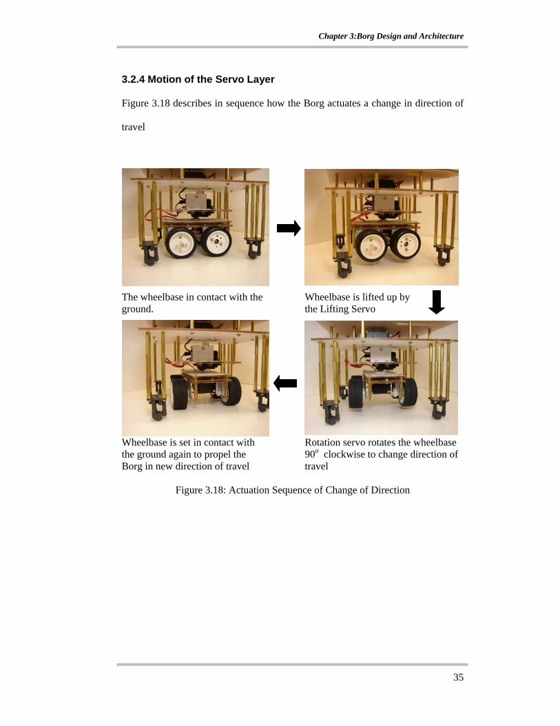
3.2.4 Motion of the Servo Layer
Figure 3.18 describes in sequence how the Borg actuates a change in direction of
travel
The wheelbase in contact with the ground.
Wheelbase is lifted up by the Lifting Servo
Wheelbase is set in contact with the ground again to propel the Borg in new direction of travel
Rotation servo rotates the wheelbase 90o clockwise to change direction of travel
Figure 3.18: Actuation Sequence of Change of Direction
Chapter 3:Borg Design and Architecture
36
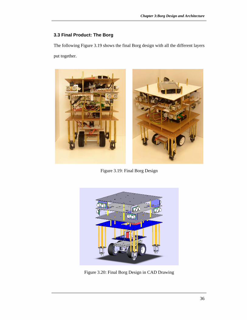
3.3 Final Product: The Borg
The following Figure 3.19 shows the final Borg design with all the different layers
put together.
Figure 3.19: Final Borg Design
Figure 3.20: Final Borg Design in CAD Drawing
Chapter 4: Algorithm Implementation
37
CHAPTER 4: ALGORITHM IMPLEMENTATION In this chapter, the implementation of the algorithm on actual hardware would be
presented with an example of a 4 Borg initial configuration. The design definition
is stated again here:
I. The robotic units are constrained to only move in a square or rectangular
environment.
II. The obstacles will not have any angular extrusions
III. The path that the robotic units have to reconfigure to is at least the width of one robotic unit.
IV. Any formation that the robotic units are laid out in must have at least one
side facing another robotic unit.
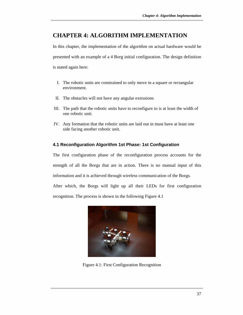
4.1 Reconfiguration Algorithm 1st Phase: 1st Configuration
The first configuration phase of the reconfiguration process accounts for the
strength of all the Borgs that are in action. There is no manual input of this
information and it is achieved through wireless communication of the Borgs.
After which, the Borgs will light up all their LEDs for first configuration
recognition. The process is shown in the following Figure 4.1
Figure 4.1: First Configuration Recognition
Chapter 4: Algorithm Implementation
38
There are 2 problems that this method faces. Firstly, some of the LED mounts are
not precisely facing the light sensor of the other Borg. Hence, this sometimes
causes the Borg to fail to recognize that there is another Borg beside it and this
would cause the formation to fail when the Borgs move off as a unit. Also, there
were a few occasions that a Borg reports more than the correct number of Borgs
beside it. This could be due to the light reflecting from the Borg surface to another
sensor that is not supposed to sense any light, thus causing the incorrect
assumption that there is another Borg on that side.
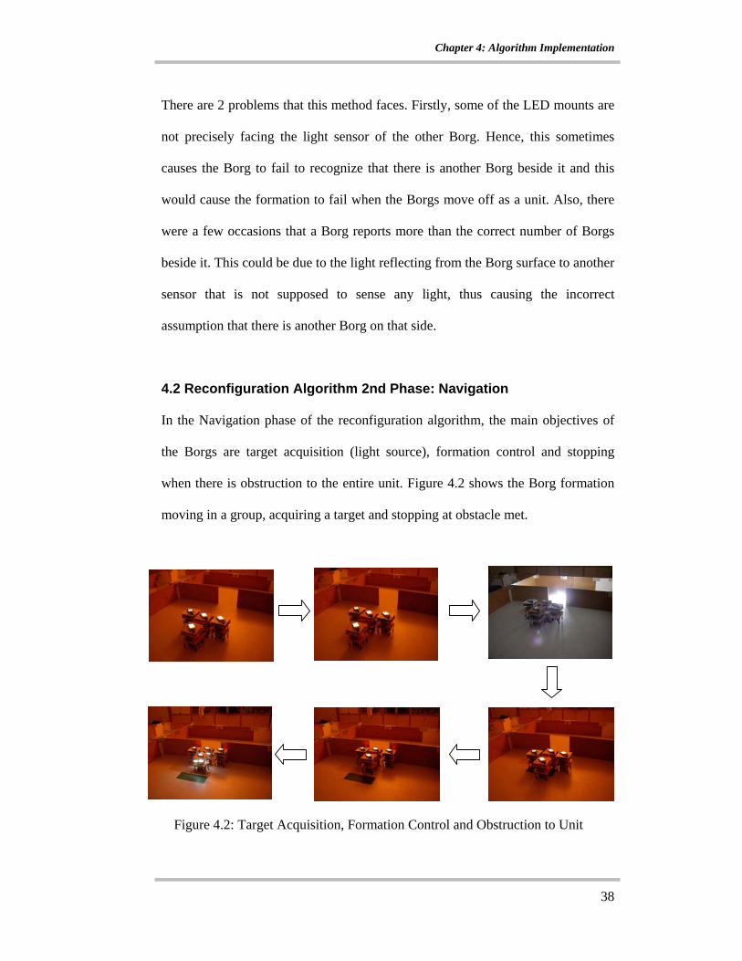
4.2 Reconfiguration Algorithm 2nd Phase: Navigation In the Navigation phase of the reconfiguration algorithm, the main objectives of
the Borgs are target acquisition (light source), formation control and stopping
when there is obstruction to the entire unit. Figure 4.2 shows the Borg formation
moving in a group, acquiring a target and stopping at obstacle met.
Figure 4.2: Target Acquisition, Formation Control and Obstruction to Unit
Chapter 4: Algorithm Implementation
39
The problem faced in this part of the algorithm is that sometimes, more than 1
Borg would detect the target. This then results in more than 1 stop all message
sent to all the other Borgs, which would cause the entire unit to stop for a little
while longer than it should have. The solution to this problem is to have more than
1 wireless message-receiving loop in 1 run of the navigation part of the algorithm.
This makes message receiving more efficient and reduce the stopping time of the
entire unit when light is detected.
Another slight problem is that the entire unit cannot move together smoothly,
there will always be one Borg moving out of formation and leading to a whole
chain of jagged movements by the entire unit. Setting all the Borgs to move at the
same speed has minimized this problem.
4.3 Algorithm 3rd Phase: Reconfiguration The reconfiguration phase of the algorithm has 1 main objective, getting all the
Borgs to form a line behind the Borg that is in the through path. This is achieved
in 3 processes.
Chapter 4: Algorithm Implementation
40
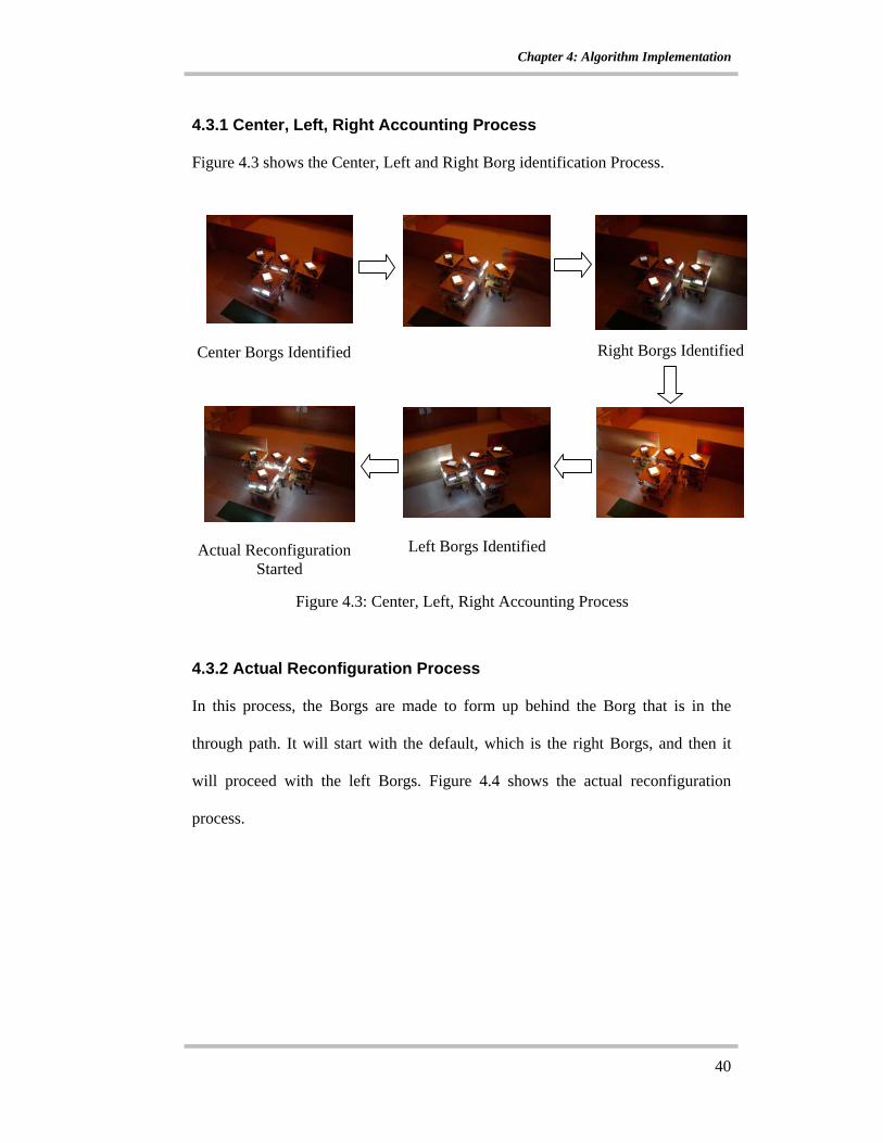
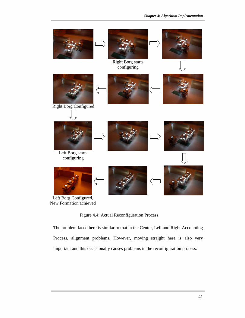
4.3.1 Center, Left, Right Accounting Process Figure 4.3 shows the Center, Left and Right Borg identification Process. 4.3.2 Actual Reconfiguration Process In this process, the Borgs are made to form up behind the Borg that is in the
through path. It will start with the default, which is the right Borgs, and then it
will proceed with the left Borgs. Figure 4.4 shows the actual reconfiguration
process.
Center Borgs Identified
Right Borgs Identified
Left Borgs Identified Actual Reconfiguration
Started
Figure 4.3: Center, Left, Right Accounting Process
Chapter 4: Algorithm Implementation
41
The problem faced here is similar to that in the Center, Left and Right Accounting
Process, alignment problems. However, moving straight here is also very
important and this occasionally causes problems in the reconfiguration process.
Right Borg starts
configuring
Right Borg Configured
Left Borg starts
configuring
Left Borg Configured,
New Formation achieved
Figure 4.4: Actual Reconfiguration Process

Chapter 4: Algorithm Implementation
42
4.3.3 New Formation Recognition Process
This process is very similar to the 1st configuration phase. It requires the Borgs to
recognize the new formation that they are now in and move off together as a unit
in that formation. Figure 4.5 shows them with all the LEDs off and then moving
off as a unit across the narrow channel.
The difficulty in this process is that after the actual reconfiguration process, the
Borgs are sometimes poorly aligned. This occasionally causes the Borgs to not
recognize that there is another Borg behind or in front of it because it cannot sense
the light coming from the other Borg’s LEDs. However, by slowing down the
speed of the Borg movements, this problem has been minimized.
Figure 4.5: Moving Together in New Formation

Conclusion
43
CONCLUSION From the studies that were conducted during the literature survey, it could be
observed that the focus of the reconfigurable system, at least among the research
that were studied in the literature survey, was more on the mechanical attachment
between the modular units. Hence, given the project objective, research on
autonomous and cooperative systems gave more insight into the basic
requirements of the required autonomous reconfigurable system. However, the
challenging aspect of this project is that a formation needs to be held and then
changed to suit the environmental constrain imposed on it. This project objective
required an original approach to the problem and the algorithm presented in this
report has successfully accomplished this.
The use of LEDs and light sensors for positional recognition is a novel and
effective approach to differentiate the robotic units that were in the through path
and those that were beside the through path during the reconfiguration process.
However, the use of light sensors meant that calibration was required as most of
the time, sensors readings varies from sensor to sensor. Hence the appropriate
values to be used in the program that would translate to sensible actions in
hardware had to be obtained through experimentation. Experiments were also
carried out on the sonar sensors, which eventually enabled the sonar sensors to
help keep the formation of the entire unit. As moving straight played an important
role in the reconfiguration algorithm, a unique wheelbase had to be specially
designed and fabricated just to achieve moving straight.
Conclusion
44
In the reconfiguration algorithm that was implemented on this system,
communication was very important and hence the amount of work put into
establishing a wireless network among the robotic units that are in action.
However, the implementation of wireless communication into the program codes
proved to be most difficult. Thus, much effort had to be put into the study of
Winsock programming to incorporate the wireless messaging codes in C++ into
the program codes using Embedded Visual Basic C++ software.
Testing of the reconfiguration system started out with only 2 units and then
proceeded to 3 and eventually to 4 units. The progressive testing of the system is
very time consuming as testing was carried out from mid December 2003 to end
of March 2004. However, this way of testing the system helped to expose the
areas that were overlooked when developing the reconfiguration algorithm. With
the repeated testing of the system especially when it came to 4 robotic units, the
reconfiguration algorithm was time and time again fine tuned by learning from the
many failed attempts to reconfigure. Eventually, the process of repeated testing
greatly strengthened the reconfiguration algorithm, making it more robust. Hence,
the project objective of autonomous reconfiguration triggered by environmental
constrains was finally achieved by taking advantage of the novel robotic unit
design, the wireless communication that was implemented into the program, the
calibration of the sensors and the repeated testing of the unique reconfiguration
algorithm on the actual hardware.

Recommendation
45
RECOMMENDATION
There are 2 areas that the author recommends for improvement.
Most of the research done on the reconfigurable robots focuses on the connection
between the modules, but as can be seen from this report; the Borgs are not
connected to one another. The sensors that are mounted on the corners of each
side hold their formation but not physically. This makes the design easy to work
with but the disadvantage is that the formation is not held tight. This occasionally
causes problems in the reconfiguration process. More work could be done in the
future in this aspect of hardware, a simple connection between the robotic units
could hold the formation tighter.
The Devantech SRF08 Range Finders has an incorporated light sensor. This light
sensor often gave inconsistent results even between sensors despite being in the
same conditions. Perhaps a more accurate photocell sensor could be used here to
avoid the many problems that were faced during the 1st configuration and
reconfiguration phase due to the insensitivity of the light sensors.

References
46
REFERENCES [1] Mark Yim, Kimon Roufas, David Duff, Ying Zhang, Craig Eldershaw and
Sam Homans, “Modular Reconfigurable Robots in Space Applications”, Autonomous Robots, 14, 225 – 237, 2003
[2] Andres Castano, Alberto Behar and Peter M. Will, “ The Conro modules for Reconfigurable Robots”, IEEE/ASME Transactions on Mechatronics, vol 7, no. 4, Dec 2002
[3] Kasper Stoy, Wei-Min Shen and Peter M. Will, “Using Role-Based control to produce locomotion in chain-type Self-Reconfigurable Robots”, IEEE/ASME Transactions on Mechatronics, vol 7, no. 4, Dec 2002
[4] Tucker Balch and Lynne E.Parker, “Robot Teams”, A K Peters, Ltd, 2002 pp 37 – 82, pp 293 - 313
[5] T. Fukuda and S Nakagawa, “A Dynamically Reconfigurable Robotic Systems” Proceedings of IECON, pp 588 – 595, 1987
[6] Guy Theraulaz and Eric Bonabeau, “Coordination in Distributed Building”, Science, vol 259, Aug 1995
[7] Ronald C. Arkin, “Cooperation without Communication: Multiagent Schema-Based Robot Navigation”, Journal of Robotic Systems 9(3), 351-364, 1992 by John Willey & Sons, Inc
[8] H. M. Deitel, P. J. Deitel, “C How To Program”, Prentice-Hall Inc., 1994.
[9] Anthony Jones, Jim Ohlund, “Network Programming For Microsoft Windows”, Microsoft Press, 1999.
[10] Bob Quinn, Dave Shute, “Windows Sockets Network Programming”, Addison Wesley Pub. Co., 1996.
[11] Douglas Boling, “Programming Microsoft Windows CE”, Microsoft Press, Second Edition, 2001
[12] Richard C. Leinecker, Tom Archer “Visual C++ 6 Bible”, IDG Books Worldwide
Appendix A: Sonar Sensor Experiment Set Up
47
APPENDIX A : SONAR SENSOR EXPERIMENT SET UP
4 mm plywood
Experimental Set up
Appendix B: Experiment Set Up for Borg-To-Borg Proximity Range
48
APPENDIX B: EXPERIMENT SETUP FOR BORG-TO-BORG PROXIMITY RANGE
Experiment Set up
Appendix C: Light Intensity Experiment Set Up
49
APPENDIX C: LIGHT INTENSITY EXPERIMENT SETUP
Experiment Setup
Appendix D: Specifications
50
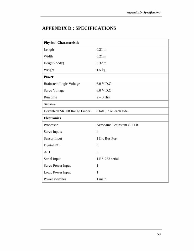
APPENDIX D : SPECIFICATIONS Physical Characteristic
Length 0.21 m
Width 0.21m
Height (body) 0.32 m
Weight 1.5 kg
Power
Brainstem Logic Voltage 6.0 V D.C
Servo Voltage 6.0 V D.C
Run time 2 – 3 Hrs
Sensors
Devantech SRF08 Range Finder 8 total, 2 on each side.
Electronics
Processor Acroname Brainstem GP 1.0
Servo inputs 4
Sensor Input 1 II c Bus Port
Digital I/O 5
A/D 5
Serial Input 1 RS-232 serial
Servo Power Input 1
Logic Power Input 1
Power switches 1 main.

Appendix E: Component Price List / Expenditure List
51
APPENDIX E: COMPONENT PRICE LIST / EXPENDITURE LIST
Components Provided by CoSy Lab (per robot)
Part no Component Description Quantity Cost/part Total Amount
1 Brainstem GP 1.0 1 $133 $133
2 Modified Servo R29 MX 400 1 $20 $20
3 Devantech SRF08 Range Finder 8 $85.00 $680
Components Purchased for Fabrication of Borg (per robot)
Part No. Component Description Quantity Cost/part Total Amount
1 Acrylic Sheet 2 $8.50 $17.00
2 Ball Caster 4 $4.00 $16.00
3 Servo to Wheel Horn attachments 4 $2.80 $11.20
4 Gears for wheelbase 2 $4.50 $9.00
5 Rubber Tyres (pair) 2 $8.00 $16.00
6 HI Tec Hs 322 HD Servo 2 $18.00 $36.00
7 Rechargeable Battries 8 $5.00 $40.00
8 Spacers 82 $0.25 $20.50
9 Miscellaneous parts - $10.00 $10.00
TOTAL COST OF COMPONENTS PURCHASED FOR FABRICATION : $175.70 TOTAL COST OF EACH ROBOT(inclusive of parts provided by lab) : $1,008.70 Total Number of Borgs Fabricated : 4