recommendations on harmonized europe-wide technical
TRANSCRIPT

Resolution No. 61, Revision 2
Recommendations on Harmonized Europe-wide Technical Requirements
for Inland Navigation Vessels
Recomm
endations on Harm
onized Europe-wide Technical Requirem
ents for Inland Navigation Vessels
Resolution No. 61, Revision 2
UN
ECEU
NITED
NATIO
NS

ECE/TRANS/SC.3/172/Rev.2
ECONOMIC COMMISSION FOR EUROPE
Recommendations on Harmonized Europe-wide
Technical Requirements for Inland Navigation Vessels
Resolution No. 61 Revision 2
Geneva, 2020

Resolution No. 61 Revision 2
UNITED NATIONS PUBLICATION
eISBN: 978-92-1-047489-4
NOTE
The designations employed and the presentation of the material in this publication do not imply the expression of any opinion whatsoever on the part of the Secretariat of the United Nations concerning the legal status of any country, territory, city or area, or of its authorities, or concerning the delimitation of its frontiers or boundaries.
ECE/TRANS/SC.3/172/Rev.2
Copyright © United Nations, 2019
All rights reserved.No part of this publication may, for sales purposes, be reproduced, stored in
a retrieval system or transmitted in any form or by any means, electronic, electrostatic, magnetic tape, mechanical, photocopying or otherwise,
without prior permission in writing from the United Nations.

iiiiii
United Nations Economic Commission for Europe
The United Nations Economic Commission for Europe (UNECE) is one of the five United Nations regional commissions, administered by the Economic and Social Council (ECOSOC). It was established in 1947 with the mandate to help rebuild post-war Europe, develop economic activity and strengthen economic relations among European countries, and between Europe and the rest of the world. During the Cold War, UNECE served as a unique forum for economic dialogue and cooperation between East and West. Despite the complexity of this period, significant achievements were made, with consensus reached on numerous harmonization and standardization agreements.
In the post-Cold War era, UNECE acquired not only many new member States, but also new functions. Since the early 1990s the organization has focused on analyses of the transition process, using its harmonization experience to facilitate the integration of Central and Eastern European countries into the global markets.
UNECE is the forum where the countries of western, central and eastern Europe, central Asia and North America – 56 countries in all – come together to forge the tools of their economic cooperation. That cooperation concerns economics, statistics, environment, transport, trade, sustainable energy, timber and habitat. The Commission offers a regional framework for the elaboration and harmonization of conventions, norms and standards. The Commission’s experts provide technical assistance to the countries of South-East Europe and the Commonwealth of Independent States. This assistance takes the form of advisory services, training seminars and workshops where countries can share their experiences and best practices.
Transport in UNECE
The UNECE Sustainable Transport Division is the secretariat of the Inland Transport Committee (ITC) and the ECOSOC Committee of Experts on the Transport of Dangerous Goods and on the Globally Harmonized System of Classification and Labelling of Chemicals. The ITC and its 17 working parties, as well as the ECOSOC Committee and its sub-committees are intergovernmental decision-making bodies that work to improve the daily lives of people and businesses around the world, in measurable ways and with concrete actions, to enhance traffic safety, environmental performance, energy efficiency and the competitiveness of the transport sector.
The ECOSOC Committee was set up in 1953 by the Secretary-General of the United Nations at the request of the Economic and Social Council to elaborate recommendations on the transport of dangerous goods. Its mandate was extended to the global (multi-sectoral) harmonization of systems of classification and labelling of chemicals in 1999. It is composed of experts from countries which possess the relevant expertise and experience in the international trade and transport of dangerous goods and chemicals. Its membership is restricted in order to reflect a proper geographical balance between all regions of the world and to ensure adequate participation of developing countries. Although the Committee is a subsidiary body of ECOSOC, the Secretary-General decided in 1963 that the secretariat services would be provided by the UNECE Sustainable Transport Division.
ITC is a unique intergovernmental forum that was set up in 1947 to support the reconstruction of transport connections in post-war Europe. Over the years, it has specialized in facilitating the harmonized and sustainable development of inland modes of transport. The main results of this persevering and ongoing work are reflected, among other things, (i) in 58 United Nations conventions and many more technical regulations, which are updated on a regular basis and provide an international legal framework for the sustainable development of national and international road, rail, inland water and intermodal transport, including the

iv
Resolution No. 61 Revision 2
transport of dangerous goods, as well as the construction and inspection of road motor vehicles; (ii) in the Trans-European North-south Motorway, Trans-European Railway and the Euro-Asia Transport Links projects, that facilitate multi-country coordination of transport infrastructure investment programmes; (iii) in the TIR system, which is a global customs transit facilitation solution; (iv) in the tool called For Future Inland Transport Systems (ForFITS), which can assist national and local governments to monitor carbon dioxide (CO2) emissions coming from inland transport modes and to select and design climate change mitigation policies, based on their impact and adapted to local conditions; (v) in transport statistics – methods and data – that are internationally agreed on; (vi) in studies and reports that help transport policy development by addressing timely issues, based on cutting-edge research and analysis. ITC also devotes special attention to Intelligent Transport Services (ITS), sustainable urban mobility and city logistics, as well as to increasing the resilience of transport networks and services in response to climate change adaptation and security challenges.
In addition, the UNECE Sustainable Transport and Environment Divisions, together with the World Health Organization (WHO) – Europe, co-service the Transport Health and Environment Pan-European Programme (THE PEP).
Finally, as of 2015, the UNECE Sustainable Transport Division is providing the secretariat services for the Secretary General’s Special Envoy for Road Safety Mr. Jean Todt.

vv
Foreword
The pan-European requirements for the construction of inland navigation vessels were first harmonized in 1975 with the adoption of the Recommendations on Technical Requirements for Inland Navigation Vessels (resolution No. 17) by the Working Party on Inland Water Transport (SC.3) of the United Nations Economic Commission for Europe (UNECE). Since that time, the recommendations have been continuously updated, following the recent changes in the regulatory documents of member States, legislation of the European Union, regulations of River Commissions and international standards.
In 2006, SC.3 undertook a fundamental revision of its 1975 recommendations and adopted the Recommendations on Harmonized Europe-Wide Technical Requirements for Inland Navigation Vessels (annex to resolution No. 61). These recommendations establish a pan-European regime of technical requirements for inland navigation vessels that transport goods and passengers internationally. They are the result of Government efforts to unify divergent regulations in force in different intergovernmental organizations and ECE member countries.
The recommendations are intended to facilitate the recognition of ship’s certificates, thus eliminating the need for more than one inspection of vessels engaged in international transport by inland waterways. They also contain strict regulations on limitation of air and water pollution and on the abatement of noise, the internationally agreed standards for minimum manning requirements and the working and rest hours of crews.
The annex to resolution No. 61 was revised and adopted by SC.3 in 2010 by its resolution No. 68. In 2011-2016, next amendments were prepared by the Group of Volunteer Experts on resolution No. 61 based on the latest amendments to Directive 2006/87/EC of the European Union laying down technical requirements for inland waterway vessels. They were adopted by SC.3 as resolutions Nos. 72, 76 and 86 (ECE/TRANS/SC.3/172/Rev.1/Amend.1 to 4).
With a view to further develop resolution No. 61, SC.3 adopted the second revision of the annex to resolution No. 61 as its resolution No. 91 on 5 October 2018 at its sixty-second session. The present second revision includes the four amendments and newly adopted texts of section 8B-4, Requirements concerning equipment for the treatment of domestic waste water, chapter 19B, Subjects for possible reductions of the technical requirements applicable to craft on inland waterways of zones 3 and 4, appendix 8, On-board sewage treatment plants. Supplementary provisions and certificate models, and appendix 9, On-board sewage treatment plant. Test procedure.

vi
Resolution No. 61 Revision 2

viivii
Contents
Contents
Resolution No. 61 - Recommendations on Harmonized Europe-Wide Technical Requirements for Inland Navigation Vessels ............................................................ xv
ANNEX Recommendations on Harmonized Europe-Wide Technical Requirements for Inland Navigation Vessels ............................................................ 1
CHAPTER 1 - General Provisions .................................................................................. 11-1 Purpose and scope ....................................................................................................................................................... 11-2 Definitions .......................................................................................................................................................................... 2
CHAPTER 2 - Procedure and Rules for the Inspection of Inland Navigation Vessels .............................................................................................................................. 11
2-1 Operating ability ............................................................................................................................................................. 112-2 Purpose of the inspection ........................................................................................................................................ 112-3 Kinds of inspection ....................................................................................................................................................... 112-4 Periodic inspection ....................................................................................................................................................... 112-5 Competent authority on the inspection of vessels .................................................................................. 122-6 Additional requirements in the course of the inspection .................................................................... 122-7 Unique European Vessel Identification Number ........................................................................................ 12
CHAPTER 3 - Shipbuilding Requirements .................................................................. 153-1 Strength ............................................................................................................................................................................... 153-2 Structural requirements ............................................................................................................................................. 153-3 Stability ................................................................................................................................................................................. 153-4 Subdivision ........................................................................................................................................................................ 163-5 Criteria for checking the stability of vessels .................................................................................................. 173-6 Other provisions ............................................................................................................................................................. 23
CHAPTER 3A - Fire Protection....................................................................................... 253A-1 Structural requirements ............................................................................................................................................. 253A-2 Means of escape ............................................................................................................................................................. 253A-3 Storage of flammable liquids ................................................................................................................................. 26
CHAPTER 4 - Safety Clearance, Freeboard and Draught Marks ............................. 274-1 General ................................................................................................................................................................................. 274-2 Types of vessels ............................................................................................................................................................... 274-3 Draught marks and freeboard mark ................................................................................................................... 274-4 Freeboard ............................................................................................................................................................................ 294-5 Safety clearance .............................................................................................................................................................. 324-6 Arrangement of openings and coamings ...................................................................................................... 324-7 Special requirements for safety clearance and freeboard in zone 4 .............................................. 324-8 Maximum loaded draught of vessels whose holds are not always closed so as to be
spray-proof and weathertight ............................................................................................................................... 33
CHAPTER 5 - Manoeuvrability ...................................................................................... 355-1 General ................................................................................................................................................................................. 355-2 Navigation tests .............................................................................................................................................................. 355-3 Test area ............................................................................................................................................................................... 35

viii
Resolution No. 61 Revision 2
5-4 Loading of vessels and convoys during navigation tests ..................................................................... 355-5 Use of on-board facilities for navigation test ................................................................................................ 355-6 Speed (forward) .............................................................................................................................................................. 365-7 Stopping capacity ......................................................................................................................................................... 365-8 Capacity for going astern .......................................................................................................................................... 365-9 Capacity for changing course ................................................................................................................................ 365-10 Turning capacity ............................................................................................................................................................. 36
CHAPTER 6 - Steering System....................................................................................... 376-1 General requirements ................................................................................................................................................. 376-2 Steering apparatus drive unit ................................................................................................................................. 376-3 Hydraulic drive unit ...................................................................................................................................................... 376-4 Power source .................................................................................................................................................................... 386-5 Manual drive ..................................................................................................................................................................... 386-6 Rudder-propeller, water-jet, cycloidal-propeller and bow thruster systems ............................ 386-7 Indicators and monitoring devices ..................................................................................................................... 386-8 Rate-of-turn regulators ............................................................................................................................................... 386-9 Acceptance and periodical inspections .......................................................................................................... 39
CHAPTER 7 - Wheelhouse.............................................................................................. 417-1 General requirements ................................................................................................................................................. 417-2 Unobstructed view ....................................................................................................................................................... 417-3 Requirements concerning control, display and monitoring equipment ................................... 417-3A Requirements concerning onboard computers ........................................................................................ 427-4 Radar equipment and rate-of-turn control ................................................................................................... 437-5 Alarm system .................................................................................................................................................................... 447-6 Special wheelhouse arrangements for radar steering by one person ......................................... 447-7 Movable wheelhouses ............................................................................................................................................... 45
CHAPTER 8 - Engine Design .......................................................................................... 478-1 Machinery ........................................................................................................................................................................... 478-2 Automation ....................................................................................................................................................................... 50
CHAPTER 8A - Exhaust and Pollutant Particulate Emissions from Diesel Engines ............................................................................................................................. 53
8A-1 Definitions .......................................................................................................................................................................... 538A-2 Fundamental principles ............................................................................................................................................. 54
CHAPTER 8B - Prevention of Water Pollution and Abatement of Noise Produced by Vessels ............................................................................................................................... 57
8B-1 Requirements for collection facilities for used oil and oil-containing water ............................ 578B-2 Requirements concerning equipment for processing oil-containing water ........................... 588B-3 Requirements concerning facilities for collecting and storing domestic waste water ...... 588B-4 Requirements concerning equipment for the treatment of domestic waste water ........... 598B-5 Facilities for the collection and storage of vessel operation refuse ................................................ 658B-6 Facilities for the collection, storage and treatment of household refuse ................................... 658B-7 Requirements concerning facilities for the elimination of household and vessel
operation refuse ............................................................................................................................................................. 668B-8 Noise emitted by vessels ........................................................................................................................................... 66

ixix
Contents
CHAPTER 9 - Electrical Installations ............................................................................ 679-1 General ................................................................................................................................................................................. 679-2 Technical requirements .............................................................................................................................................. 68
CHAPTER 10 - Equipment.............................................................................................. 7910-1 Anchor and mooring equipment ........................................................................................................................ 7910-2 Miscellaneous equipment ........................................................................................................................................ 8110-3 Fire-fighting appliances ............................................................................................................................................. 8210-4 Hoisting gear, rigging and equipment ............................................................................................................. 8310-5 Life-saving appliances ................................................................................................................................................. 84
CHAPTER 11 - Working Spaces ..................................................................................... 8911-1 General ................................................................................................................................................................................. 8911-2 Protection against falling .......................................................................................................................................... 8911-3 Dimensions of working spaces ............................................................................................................................. 8911-4 Side deck ............................................................................................................................................................................. 8911-5 Access to working spaces ......................................................................................................................................... 8911-6 Exits and emergency exits ........................................................................................................................................ 9011-7 Stairs, ladders and steps ............................................................................................................................................. 9011-8 Inside spaces ..................................................................................................................................................................... 9011-9 Protection against noise and vibration ............................................................................................................ 9111-10 Hatch covers ..................................................................................................................................................................... 9111-11 Winches ............................................................................................................................................................................... 91
CHAPTER 12 - Crew Accommodation ......................................................................... 9312-1 General ................................................................................................................................................................................. 9312-2 Special design requirements .................................................................................................................................. 9312-3 Approaches, doors and stairways ........................................................................................................................ 9412-4 Daylight and lighting ................................................................................................................................................... 9412-5 Fittings .................................................................................................................................................................................. 9412-6 Galleys and day-rooms (messrooms) ................................................................................................................ 9412-7 Sanitary installations .................................................................................................................................................... 9512-8 Potable-water installations ...................................................................................................................................... 95
CHAPTER 13 - Fuel-Fired Heating, Cooking and Refrigerating Equipment (Left void) ......................................................................................................................... 96
CHAPTER 14 - Liquefied Gas Installations for Domestic Purposes ........................ 9714-1 General ................................................................................................................................................................................. 9714-2 Installation .......................................................................................................................................................................... 9714-3 Receptacles ........................................................................................................................................................................ 9714-4 Location and arrangement of the supply unit ............................................................................................ 9714-5 Spare and empty receptacles ................................................................................................................................ 9814-6 Pressure reducers ........................................................................................................................................................... 9814-7 Pressure ................................................................................................................................................................................ 9814-8 Piping and flexible tubes .......................................................................................................................................... 9814-9 Distribution system....................................................................................................................................................... 9914-10 Gas-consuming appliances and their installation ..................................................................................... 99

x
Resolution No. 61 Revision 2
14-11 Ventilation and evacuation of the combustion gases ............................................................................ 9914-12 Instructions for use and safety ............................................................................................................................... 9914-13 Inspection ........................................................................................................................................................................... 10014-14 Tests and trials .................................................................................................................................................................. 10014-15 Entry in the appropriate vessel’s paper ............................................................................................................ 101
CHAPTER 15 - Special Provisions for Passenger Vessels ......................................... 10315-1 General provisions ......................................................................................................................................................... 10315-2 Vessel's hull ........................................................................................................................................................................ 10315-3 Stability ................................................................................................................................................................................. 10515-4 Safety clearance and freeboard ............................................................................................................................ 11015-5 Maximum permitted number of passengers ............................................................................................... 11015-6 Passenger rooms and areas ..................................................................................................................................... 11015-7 Propulsion system ......................................................................................................................................................... 11415-8 Safety devices and equipment .............................................................................................................................. 11415-9 Life saving appliances ................................................................................................................................................. 11515-10 Electrical equipment .................................................................................................................................................... 11615-11 Fire protection ................................................................................................................................................................. 11815-12 Fire-fighting ....................................................................................................................................................................... 12115-12A Waste water collection and disposal facilities .............................................................................................. 12215-13 Safety organisation ....................................................................................................................................................... 12215-14 Exemptions for certain passenger vessels ...................................................................................................... 124
CHAPTER 15A - Specific Requirements for Sailing Passenger Vessels .................. 12715A-1 Application of chapter 3 to chapter 23 ............................................................................................................ 12715A-2 Exceptions for certain passenger sailing vessels ........................................................................................ 12715A-3 Stability requirements for vessels under sail ................................................................................................. 12715A-4 Shipbuilding and mechanical requirements ................................................................................................ 12815A-5 Rigging in general ......................................................................................................................................................... 12815A-6 Masts and spars in general ....................................................................................................................................... 12815A-7 Special provisions for masts .................................................................................................................................... 12915A-8 Special provisions for topmasts ............................................................................................................................ 13015A-9 Special provisions for bowsprits ........................................................................................................................... 13015A-10 Special provisions for jib-booms .......................................................................................................................... 13115A-11 Special provisions for main booms..................................................................................................................... 13115A-12 Special provisions for gaffs ....................................................................................................................................... 13115A-13 General provisions for standing and running rigging ............................................................................ 13215A-14 Special provisions for standing rigging ............................................................................................................ 13215A-15 Special provisions for running rigging ............................................................................................................. 13315A-16 Fittings and parts of the rigging ........................................................................................................................... 13315A-17 Sails ......................................................................................................................................................................................... 13415A-18 Equipment ......................................................................................................................................................................... 13415A-19 Testing ................................................................................................................................................................................... 134
CHAPTER 16 - Specific Requirements Applicable to Vessels Intended to Form Part of a Pushed or Towed Convoy or of a Side-By-Side Formation ..................... 135
16-1 Vessels suitable for pushing .................................................................................................................................... 13516-2 Pushed lighters ................................................................................................................................................................ 13516-3 Towing vessels ................................................................................................................................................................. 136

xixi
Contents
16-4 Tests on convoys of vessels ..................................................................................................................................... 13616-5 Entries on the certificate ........................................................................................................................................... 136
CHAPTER 17 - Specific Requirements Applicable to Floating Equipment ........... 13717-1 General ................................................................................................................................................................................. 13717-2 Derogations ....................................................................................................................................................................... 13717-3 Additional requirements ........................................................................................................................................... 13717-4 Residual safety clearance .......................................................................................................................................... 13817-5 Residual freeboard ........................................................................................................................................................ 13817-6 Heeling test ....................................................................................................................................................................... 13817-7 Confirmation of stability ............................................................................................................................................ 13817-8 Confirmation of stability in the case of reduced residual freeboard ............................................. 14017-9 Draught marks and draught scales..................................................................................................................... 14117-10 Floating equipment without confirmation of stability .......................................................................... 14117-11 Attestation of a recognized classification society ...................................................................................... 141
CHAPTER 18 - Specific Requirements Applicable to Worksite Craft ..................... 14318-1 General ................................................................................................................................................................................. 14318-2 Derogations ....................................................................................................................................................................... 14318-3 Safety clearance and freeboard ............................................................................................................................ 14318-4 Attestation of a recognized classification society ...................................................................................... 14318-5 Ship’s boats ........................................................................................................................................................................ 143
CHAPTER 19 - Specific Requirements Applicable to Historic Vessels (Left void) ... 144
CHAPTER 19A - Specific Requirements Applicable to Canal Barges (Left void) .... 145
CHAPTER 19B - Subjects for Possible Reductions of the Technical Requirements Applicable to Craft on Inland Waterways of Zones 3 and 4 ......... 146
CHAPTER 20 - Specific Requirements Applicable to Sea-Going Ships ................. 14720-1 General ................................................................................................................................................................................. 14720-2 Minimum crew ................................................................................................................................................................ 148
CHAPTER 20B - Special Provisions Applicable to River-Sea Navigation Vessels.... 14920В-1 General provisions ......................................................................................................................................................... 14920В-2 Documents ........................................................................................................................................................................ 15020В-3 Hull .......................................................................................................................................................................................... 15120В-4 Fire protection ................................................................................................................................................................. 15320B-5 Freeboard and load line ............................................................................................................................................. 15320B-6 Ship machinery and arrangements .................................................................................................................... 15420B-7 Power plant and systems .......................................................................................................................................... 15820В-8 Specific requirements applicable to the vessels forming the pushed river-sea
navigation convoys....................................................................................................................................................... 158
CHAPTER 21 - Specific Requirements Applicable to Recreational Craft .............. 16121-1 General ................................................................................................................................................................................. 16121-2 Requirements to recreational vessels ................................................................................................................ 16121-3 Applicability of chapter 23 ....................................................................................................................................... 162

xii
Resolution No. 61 Revision 2
CHAPTER 22 - Stability of Vessels Carrying Containers ........................................... 16322-1 General ................................................................................................................................................................................. 16322-2 Method A ............................................................................................................................................................................ 16322-3 Method B ............................................................................................................................................................................ 165
CHAPTER 22A - Specific Requirements Applicable to Craft Longer Than 110 m .... 16722A-1 Application of chapter 2 ............................................................................................................................................ 16722A-2 Application of chapter 3 to chapter 23 ............................................................................................................ 16722A-3 Strength ............................................................................................................................................................................... 16722A-4 Buoyancy and stability................................................................................................................................................ 16722A-5 Additional requirements ........................................................................................................................................... 169
CHAPTER 22B - Specific Requirements Applicable to High-Speed Vessels ......... 17122B-1 General ................................................................................................................................................................................. 17122B-2 Seats and seat belts ...................................................................................................................................................... 17122B-3 Freeboard ............................................................................................................................................................................ 17122B-4 Buoyancy, stability and subdivision.................................................................................................................... 17122B-5 Wheelhouse ...................................................................................................................................................................... 17122B-6 Safety information ......................................................................................................................................................... 17222B-7 Exits and evacuation routes .................................................................................................................................... 17222B-8 Fire protection ................................................................................................................................................................. 17222B-9 Additional requirements ........................................................................................................................................... 172
CHAPTER 23 - Crews ....................................................................................................... 17323-1 General ................................................................................................................................................................................. 17323-2 Crew members ................................................................................................................................................................ 17323-3 Crew members physical fitness ............................................................................................................................ 17523-4 Proof of qualifications service record ................................................................................................................ 17523-5 Operating modes ........................................................................................................................................................... 17623-6 Mandatory rest period ................................................................................................................................................ 17623-7 Change or repetition of operating mode ....................................................................................................... 17623-8 Ship’s log, tachograph ................................................................................................................................................. 17723-9 Equipment of vessels ................................................................................................................................................... 17823-10 Minimum crew for self-propelled cargo vessels and pushers ........................................................... 17923-11 Minimum crew for pushed convoys, side-by-side formations and other rigid
formations .......................................................................................................................................................................... 17923-12 Minimum crew for passenger vessels ............................................................................................................... 18023-13 Manning of vessels whose minimum equipment referred to in section 23-9 is
incomplete ......................................................................................................................................................................... 18123-14 Minimum crews for other vessels ........................................................................................................................ 181
CHAPTER 24 - Transitional and Final Provisions (Left void) .................................... 182
APPENDIX 1 - List of European Inland Waterways Divided Geographically into Zones 1, 2 and 3 (Paragraph 1-1.5 of the Recommendations) ............................... 183
APPENDIX 2 - Model Ship’s Certificate (Paragraph 2-1.2 of the Recommendations) ........................................................................................................ 206
xiiixiii
Contents
APPENDIX 3 - Safety Signs and Signals To Be Used On Board Inland Navigation Vessels.......................................................................................................... 219
APPENDIX 4 - Alternative Manoeuvrability Test Procedures and Criteria in Accordance with 5-2.1 ................................................................................................... 221
APPENDIX 5 - Model of a Service Record ................................................................... 253
APPENDIX 6 - Criteria for the Approval of Classification Societies ....................... 266
APPENDIX 7 - Requirements Concerning Lights and the Colour of Signal Lights on Vessels, Intensity and Range of Signal Lights on Vessels and General Technical Specifications Applicable to Radar Equipment ............... 268
APPENDIX 8 - On-board Sewage Treatment Plants. Supplementary Provisions and Certificate Models .................................................................................................. 275
APPENDIX 9 - On-board Sewage Treatment Plant. Test Procedure ....................... 294


xv
Recommendations on Harmonized Europe-Wide Technical Requirements for Inland Navigation Vessels
Resolution No. 61(adopted by the Working Party on Inland Water Transport on 16 March 2006)
The Working Party on Inland Water Transport,
Considering resolution No. 17, revised (TRANS/SC.3/103, annex 1), containing in its annex the recommendations on Technical Requirements for Inland Navigation Vessels as amended (TRANS/SC.3/104 and Adds.1-6),
Considering also resolution No. 33 (TRANS/SC.3/131) on Ship’s Certificate,
Recalling the recommendation of the Inland Transport Committee that the Working Party should continue its efforts towards a full reciprocal recognition of ship’s certificates and should, to this end, undertake updating the recommendations on Technical Requirements for Inland Navigation Vessels (ECE/TRANS/97, paragraph 104),
Recalling further the Declaration adopted by the Pan-European Conference on Inland Waterway Transport (Rotterdam, 5-6 September 2001) inviting the European Commission, UNECE and the two river commissions to intensify their cooperation on pan-European harmonization of technical, safety and manning requirements (TRANS/SC.3/2001/10, point 12),
Believing that the harmonization of national and international (within subregional groupings) technical requirements for vessels applied on European inland waterways would be of great benefit to international transport by inland waterway, the safety of navigation, the protection of human health and life, as well as the protection of the environment,
Bearing in mind the report of the Working Party on the Standardization of Technical and Safety Requirements in Inland Navigation, on its twenty-ninth session in so far as the item on the amendment of the recommendations on Technical Requirements for Inland Navigation Vessels is concerned (TRANS/SC.3/WP.3/58, paragraphs 4-22),
1. Adopts the text of recommendations on Harmonized Europe-Wide Technical Requirements for Inland Navigation Vessels annexed to this resolution,
2. Decides to cancel resolution No. 17, revised, as well as resolutions Nos. 10, 11, 23, 28, 32, 33, 34, 36, 38, 42, 50, 53, 55 and 56 which are replaced by this resolution,
3. Requests Governments to accept the ship’s certificate issued in accordance with the annexed recommendations as documentary evidence that the vessel complies with the recommendations on Harmonized Europe-Wide Technical Requirements for Inland Navigation Vessels (as set out in document ECE/TRANS/SC.3/172 as amended) and to take it duly into account when issuing other certificates, if required, for given waterways. In this connection, technical inspection of the vessel may be wholly or partly dispensed with, in so far as regulations in force so permit;
4. Invites Governments to inform the Executive Secretary of the United Nations Economic Commission for Europe whether they accept this resolution,
5. Requests the Executive Secretary of the United Nations Economic Commission for Europe to place the question of the application of this resolution periodically on the agenda of the Working Party on Inland Water Transport.


1
CHAPTER 1 - General Provisions
ANNEX
RECOMMENDATIONS ON HARMONIZED EUROPE-WIDE TECHNICAL REQUIREMENTS FOR INLAND NAVIGATION VESSELS
CHAPTER 1 - General Provisions
1-1 Purpose and scope
1-1.1 The purpose of this text is to provide recommendations on the design and equipment of inland navigation vessels with a view, in particular, to promoting the safety of vessels and crews; this text is not a substitute for national laws and regulations.
1–1.2 In general, these recommendations shall, with due regard to definitions in 1–2, apply to the following craft:
(i) Vessels having a length L of 20 m or more;
(ii) Vessels for which the product of L × B × T is a volume of 100 m3 or more.
1-1.3 These recommendations shall also apply, with due regard to definitions in 1–2, to all of the following craft:
(i) Tugs and pushers, designated to tow or to push or to move alongside vessels as referred to in 1-1.2;
(ii) Vessels intended for passenger transport which carry more than 12 people in addition to the crew.
1-1.4 In general, these recommendations shall not apply to:
(i) Ferries;
(ii) Naval vessels.
1-1.5 For the purpose of these recommendations, European inland waterways shall be classified as follows:
Zone 1 (wave height of up to 2.0 m): the waterways listed in chapter I of appendix 1 to these recommendations;
Zone 2 (wave height of up to 1.2 m): the waterways listed in chapter II of appendix 1 to these recommendations;
Zone 3 (wave height of up to 0.6 m): the waterways listed in chapter III of appendix 1 to these recommendations.
On inland waterways not listed in appendix 1 as belonging to navigational zones 1, 2 or 3, Administrations may establish technical requirements which differ from the provisions of these recommendations. Such technical requirements should be adapted to the geographical, hydrological and navigational conditions prevailing on the respective inland waterway and should be equally applied to all vessels navigating on this waterway. It is understood, however, that vessels allowed to navigate on inland waterways belonging to zones 1, 2 and 3, satisfy the safety requirements applied on those unclassified inland waterways with the exception of the lakes Ladoga and Onega in the Russian Federation.
1-1.6 Unless otherwise stated, the provisions of the present recommendations shall apply to new vessels that are intended to navigate in the navigational zones mentioned in 1-1.5, differentiated by the maximum significant wave height1 corresponding to a 5 % probability of over-topping.
1-1.7 These provisions shall apply to existing inland navigation vessels so long as the Administration considers them reasonable and practicable.
1 In this provision, “significant wave height” means the average of heights of 10 % of the total number of waves having the greater heights measured between wave trough and wave crest, observed over a short period.
2
Resolution No. 61 Revision 2
1-1.8 The Administration may permit derogations from these provisions for limited journeys of local interest or in harbour areas. The derogations in question and the journeys or area for which they are valid shall be specified in the ship’s certificate.
1-1.9 Vessels intended for the carriage of dangerous goods shall also satisfy the European Agreement concerning the International Carriage of Dangerous Goods by Inland Waterways (ADN).
1-2 Definitions
Types of craft
1. “Craft”: a vessel or item of floating equipment;
2. “Vessel”: an inland waterway vessel or sea-going ship;
3. “Inland waterway vessel”: a vessel intended solely or mainly for navigation on inland waterways;
4. “Sea-going ship”: a vessel intended mainly for navigation at sea;
5. “Motor vessel”: a motor cargo vessel or a motor tanker;
6. “Motor tanker”: a vessel intended for the carriage of goods in fixed tanks and built to navigate independently under its own motive power;
7. “Motor cargo vessel”: a vessel, other than a motor tanker, intended for the carriage of goods and built to navigate independently under its own motive power;
8. “Canal barge”: an inland waterway vessel not exceeding 38.5 m in length and 5.05 m in breadth and usually operating on the Rhine-Rhône Canal;
9. “Tug”: a vessel specially built to perform towing operations;
10. “Pusher”: a vessel specially built to propel a pushed convoy;
11. “Barge”: a dumb barge or tank barge;
12. “Tank barge”: a vessel intended for the carriage of goods in fixed tanks and built to be towed, either having no motive power of its own or having only sufficient motive power to perform restricted manoeuvres;
13. “Dumb barge”: a vessel, other than a tank barge, intended for the carriage of goods and built to be towed, either having no motive power of its own or having only sufficient motive power to perform restricted manoeuvres;
14. “Lighter”: a tank lighter, cargo lighter or ship-borne lighter;
15. “Tank lighter”: a vessel intended for the carriage of goods in fixed tanks, built or specially modified to be pushed, either having no motive power of its own or having only sufficient motive power to perform restricted manoeuvres when not part of a pushed convoy;
16. “Cargo lighter”: a vessel, other than a tank lighter, intended for the carriage of goods and built or specially modified to be pushed, either having no motive power of its own or having only sufficient motive power to perform restricted manoeuvres when not part of a pushed convoy;
17. “Ship-borne lighter”: a lighter built to be carried aboard sea-going ships and to navigate on inland waterways;
18. “Passenger vessel”: a vessel constructed and equipped to carry more than 12 passengers;
19. “Passenger sailing vessel”: a passenger vessel built and fitted out also with a view to propulsion under sail;
20. “Day-trip vessel”: a passenger vessel without overnight passenger cabins;
3
CHAPTER 1 - General Provisions
21. “Cabin vessel”: a passenger vessel with overnight passenger cabins;
22. “High-speed vessel”: a motorized vessel, with the exception of small craft, capable of sailing at a speed greater than 40 km/h in relation to the surface of still water, when this is stated in its ship’s certificate;
23. “Floating equipment”: a floating installation carrying working gear such as cranes, dredging equipment, pile drivers or elevators;
24. “Worksite craft”: a vessel, appropriately built and equipped for use at worksites, such as a reclamation barge, hopper or pontoon barge, pontoon or stone-dumping vessel;
25. “Recreational craft”: a vessel other than a passenger vessel, intended for sport or pleasure;
26. “Ship’s boat”: a boat for use in transport, rescue, salvage and work duties;
27. “Floating establishment”: any floating installation not normally intended to be moved, such as a swimming bath, dock, jetty or boathouse;
28. “Floating object”: a raft or other structure, object or assembly capable of navigation, not being a vessel or floating equipment or establishment;
29. “Flush-deck vessel”: a vessel which has no superstructure on its freeboard deck;
Assemblies of craft30. “Convoy”: a rigid or towed convoy of craft;
31. “Formation”: the manner in which a convoy is assembled;
32. “Rigid convoy”: a pushed convoy or side-by-side formation;
33. “Pushed convoy”: a rigid assembly of craft of which at least one is positioned in front of the one or two vessels providing the power for propelling the convoy, known as the “pusher(s)”; a convoy composed of a pusher and a pushed craft coupled so as to permit guided articulation is also considered as rigid;
34. “Side-by-side formation”: an assembly of craft coupled rigidly side by side, none of which are positioned in front of the vessel propelling the assembly;
35. “Towed convoy”: an assembly of one or more craft, floating establishments or floating objects towed by one or more vessels forming part of the convoy;
Particular areas on board36. “Machinery space”: is the part of the vessel housing the main and auxiliary machinery.
37. “Main engine room”: space where the propulsion engines are installed;
38. “Engine room”: space where combustion engines are installed;
39. “Boiler room”: a space housing a fuel-operated installation designed to produce steam or heat a thermal fluid;
40. “Enclosed superstructure”: a watertight, rigid, continuous structure with rigid walls jointed to the deck in a permanent and watertight manner;
41. “Wheelhouse”: the area which houses all the control and monitoring instruments necessary for manoeuvring the vessel;
42. “Accommodation”: a space intended for the use of persons normally living on board, including galleys, storage space for provisions, toilets and washing facilities, laundry facilities, anterooms and passageways, but not the wheelhouse;
43. “Passenger area”: areas on board intended for passengers and enclosed areas such as lounges, offices, shops, hairdressing salons, drying rooms, laundries, saunas, toilets, washrooms, passageways, connecting passages and stairs not encapsulated by walls;

4
Resolution No. 61 Revision 2
44. “Control centre”: a wheelhouse, an area which contains an emergency electrical power plant or parts thereof or an area with a centre permanently occupied by on-board personnel or crew members, such as for fire alarm equipment, remote controls of doors or fire dampers;
45. “Stairwell”: the well of an internal staircase or of a lift;
46. “Lounge”: a room of an accommodation or a passenger area. On board passenger vessels, galleys are not regarded as lounges;
47. “Galley”: a room with a stove or a similar cooking appliance;
48. “Store room”: a room for the storage of flammable liquids or a room with an area of over 4 m2 for storing supplies;
49. “Hold”: part of the vessel, bounded fore and aft by bulkheads, opened or closed by means of hatch covers, intended for the carriage of goods, whether packaged or in bulk, or for housing tanks not forming part of the hull;
50. “Fixed tank”: a tank joined to the vessel, the walls of the tank consisting either of the hull itself or of a casing separate from the hull;
51. “Working station”: an area where members of the crew carry out their duties, including gangway, derrick and ship’s boat;
52. “Passageway”: an area intended for the normal movement of persons and goods;
53. “Safe area”: the area which is externally bounded by a vertical surface running at a distance of 1/5 BWL parallel to the course of the hull in the line of maximum draught;
54. “Muster areas”: areas of the vessel which are specially protected and in which passengers muster in the event of danger;
55. “Evacuation areas”: part of muster areas of the vessel from which evacuation of persons can be carried out;
Marine engineering terms
56. “Main machinery”: is that designed to drive the propelling mechanisms and/or serving the main purpose of the craft;
57. “Auxiliary machinery”: is that which contributes to the operation of the main machinery and that which supplies the vessel with all forms of power necessary for the operation of the vessel’s various systems and installations;
58. “Plane of maximum draught”: the water plane corresponding to the maximum draught at which the craft is authorized to navigate;
59. “Safety clearance”: the distance between the plane of maximum draught and the parallel plane passing through the lowest point above which the craft is no longer deemed to be watertight;
60. “Residual safety clearance”: the vertical clearance available, in the event of the craft heeling over, between the water level and the lowest point of the immersed side, beyond which the craft is no longer regarded as watertight;
61. “Freeboard (F)”: the distance between the plane of maximum draught and a parallel plane passing through the lowest point of the gunwale or, in the absence of a gunwale, the lowest point of the upper edge of the craft’s side;
62. “Residual freeboard”: the vertical clearance available, in the event of the craft heeling over, between the water level and the upper surface of the deck at the lowest point of the immersed side or, if there is no deck, the lowest point of the upper surface of the fixed craft’s side;

5
CHAPTER 1 - General Provisions
63. “Freeboard deck”: the deck from which the freeboard is measured shall normally be the uppermost complete deck exposed to the weather, up to which the watertight bulkheads of the hull extend and below which all openings in the craft’s sides are fitted with permanent watertight closures;
In vessels having a discontinuous freeboard deck, the lowest part of the exposed deck and the continuation of that deck parallel to the upper part of the deck shall be taken as the freeboard deck;
64. “Margin line”: an imaginary line drawn on the side plating not less than 10 cm below the bulkhead deck and not less than 10 cm below the lowest non-watertight point of the side plating. If there is no bulkhead deck, a line drawn not less than 10 cm below the lowest line up to which the outer plating is watertight shall be used;
65. “Water displacement ( )”: the immersed volume of the vessel, in m3;
66. “Displacement (Δ)”: the total weight of the vessel, inclusive of cargo, in t;
67. “Block coefficient (CB)”: the ratio between the water displacement and the product of length LWL, breadth BWL and draught T;
68. “Lateral plane above water (AW)”: lateral plane of the vessel above the waterline in m2;
69. “Bulkhead deck”: the deck to which the required watertight bulkheads are taken and from which the freeboard is measured;
70. “Bulkhead”: a wall of a given height, usually vertical, partitioning the vessel and bounded by the bottom of the vessel, the plating or other bulkheads;
71. “Transverse bulkhead”: a bulkhead extending from one side of the vessel to the other;
72. “Wall”: a dividing surface, usually vertical;
73. “Partition wall”: a non-watertight wall;
74. “Length (L)”: the maximum length of the hull in m, excluding rudder and bowsprit;
75. “Length overall (LOA)”: the maximum length of the craft in m, including all fixed installations such as parts of the steering system or power plant, mechanical or similar devices;
76. “Length of waterline (LWL)”: the length of the hull in m, measured at the maximum draught;
77. “Breadth (B)”: the maximum breadth of the hull in m, measured to the outer edge of the shell plating (excluding paddle wheels, rub rails and similar);
78. “Breadth overall (BOA)”: the maximum breadth of the craft in m, including all fixed equipment such as paddle wheels, rub rails, mechanical devices and the like;
79. “Breadth of waterline (BWL)”: breadth of the hull in m, measured from the outside of the side plating at the maximum draught line;
80. “Height (H)”: the shortest vertical distance in m between the lowest point of the hull or the keel and the lowest point of the deck on the side of the craft;
81. “Draught (T)”: the vertical distance in m between the lowest point of the hull or the keel and the maximum draught line;
82. “Forward perpendicular”: the vertical line at the forward point of the intersection of the hull with the maximum draught line;
83. “Clear width of side deck”: the distance between the vertical line passing through the most prominent part of the hatch coaming on the side deck side and the vertical line passing through the inside edge of the slip guard (guardrail, foot rail) on the outer side of the side deck;
84. “Liquid cargo”: all liquids carried on the vessel, including: cargo, stores, ballast, etc.;

6
Resolution No. 61 Revision 2
85. “Stores”: cargo consumed in the operation of the vessel (fuel, lubricating oil, fresh water, provisions, etc.);
86. “Empty vessel”: a vessel that is fully prepared and equipped with machinery and systems, but with no cargo, passengers, liquid ballast or stores;
87. “Critical angle (φfl)”: angle of heel at which water begins to fill the vessel through unsecured openings, but not exceeding the angle at which the edge of the freeboard deck is submerged, or at which the middle of the bilge leaves the water;
88. “Capsizing angle (φc)”: angle of heel at which the vessel begins to capsize under the effect of the heeling moment;
89. “Permissible angle (φperm)”: angle of heel which should not be exceeded and which should be prescribed by the competent authority for the type of vessel under consideration. In general, it corresponds to the critical angle φfl, but should not be greater than the capsizing angle φc;
90. “Amidships”: is at the middle of the length L;
Steering system
91. “Steering system”: all the equipment necessary for steering the vessel, such as to ensure the manoeuvrability laid down in chapter 5;
92. “Rudder”: the rudder or rudders, with shaft, including the rudder quadrant and the components connecting with the steering apparatus;
93. “Steering apparatus”: the part of the steering system which produces the movement of the rudder;
94. “Drive unit”: the steering-apparatus drive, between the power source and the steering apparatus;
95. “Power source”: the power supply to the steering drive unit and the steering apparatus produced by an on-board network, batteries or an internal combustion engine;
96. “Steering control”: the component parts of and circuitry for the operation of a power-drive unit of the steering apparatus;
97. “Steering apparatus control unit”: the control for the steering apparatus, its drive unit and its power source;2
98. “Manual drive”: a system whereby manual operation of the hand wheel moves the rudder by means of a mechanical transmission, without any additional power source;
99. “Manually-operated hydraulic drive”: a manual control actuating a hydraulic transmission;
100. “Rate-of-turn regulator”: equipment which automatically produces and maintains a given rate of turn of the vessel in accordance with pre-selected values;
101. “Wheelhouse designed for radar navigation by one person”: a wheelhouse arranged in such a way that, during radar navigation, the vessel can be manoeuvred by one person;
Electrical equipment and automation
102. “Earthing”: means electrical connection to the mass of the hull;
103. “Hull return”: the distribution of direct or alternating current is said to be of the “hull return” type when the insulated conductors are connected to one of the feed poles and the hull or superstructure is connected to the other pole;
2 Applied to the Russian text only.

7
CHAPTER 1 - General Provisions
104. “Safe voltage”: means a voltage presenting no danger to persons. This condition shall be deemed to be satisfied if the windings of transformers, converters and other voltage-reducing devices are electrically separate and the reduced voltage of such devices or the voltage of sources of electric power does not exceed 50 V between the poles in the case of direct current, or between phases in the case of alternating current;
105. “Automated power installation”: is an installation equipped with automatic control, monitoring and protection of the main and auxiliary machinery and related systems interconnected by remote signalling devices;
106. “Automation system”: is the complex of automation elements, appliances and connections intended for performing prescribed functions in the field of control and monitoring;
107. “Automated remote control system”: is an automation system that provides control and monitoring of the operation of the vessel’s machinery from a remote control station by means of single manipulating of the control element (e.g. handle) by the operator and performs automatically all intermediate operations on preparation for putting into operation, switching on, changing operation modes, reversal, blocking and switching off the main and auxiliary machinery and its systems;
108. “Remote control system”: is an automation system that provides control and monitoring of the operation of an individual vessel’s machinery from a remote control station by means of manipulating the control element by the operator for performing all operations including intermediate ones;
109. “Alarm system”: is an automation system that provides actuating visual and acoustic signals when the controlled parameters reach the limit values or deviations from normal working ranges of the power installation occur;
110. “Safety system”: is an automation system that provides a certain automatic influence on the controlled installation in order to prevent its failure;
111. “Element of an automation system”: is electric, electronic or other device being the part of the automation system (sensor, relay, amplifier, chip, logic element, etc.);
112. “Indicator system”: is one that provides the operator with current information on the monitored physical parameters of the installation (mechanism, system) and changes in these parameters, and is capable of being incorporated into the overall system of automation;
Properties of structural components and materials
113. “Watertight”: a structural component or device so fitted as to prevent any ingress of water;
114. “Spray-proof and weather-tight”: a structural component or device so fitted that in normal conditions it allows only a negligible quantity of water to penetrate;
115. “Gastight”: a structural component or device so fitted as to prevent the ingress of gas and vapours;
116. “Non-combustible”: a substance which neither burns nor produces flammable vapours in such quantities that they ignite spontaneously when heated to approximately 750°C;
117. “Flame-retardant”: material which does not readily catch fire, or whose surface at least restricts the spread of flames pursuant to the test procedure referred to in section 15-11.1;
118. “Fire-resistance”: the property of structural components or devices as certified by the test procedure referred to in section 15-11.1;
119. “Code for Fire Test Procedures”: the International Code for the Application of Fire Test Procedures adopted under resolution MSC.61(67) by the Maritime Safety Committee of IMO;
8
Resolution No. 61 Revision 2
Other definitions
120. “Recognized classification society”: a classification society which has been recognized in accordance with the criteria and the procedures of appendix 6;
121. “Navigation lights”: appearances of navigation lights for the identification of craft;
122. “Light signals”: signal lights are the light signals emitted by signal lanterns;
123. “Radar installation”: an electronic navigational aid for detecting and displaying the surroundings and traffic;
124. “Inland ECDIS”: a standardized system for displaying electronic navigational charts for inland waters and associated information, that displays selected information from proprietary electronic navigational charts for inland waters and optionally information from other sensors of the craft;
125. “Inland ECDIS installation”: an installation for displaying electronic navigational charts for inland waters that can be operated in two different modes: information mode and navigation mode;
126. “Information mode”: use of Inland ECDIS for information purposes only without radar overlay;
127. “Navigation mode”: use of Inland ECDIS with radar overlay for navigating a craft;
128. “Oil-containing water”: mixture of water and any quantity of oil formed in the course of operation of a vessel, except for cargo waste;
129. “Domestic waste water”: waste water from galleys, messes, bathrooms (showers and wash basins) or laundries, and human waste water;
130. “Vessel operation refuse”: waste formed in the course of operation of the vessel except for cargo waste.
131. “Household refuse”: organic and inorganic household waste (e.g. remains of food, paper, glass and similar kitchen waste) which does not contain vessel operation refuse;
132. “Collective life-saving appliances”: lifeboats, liferafts, ship’s boats and life-saving buoyancy aids intended for rescue of passengers and the ship’s crew;
133. “Lifeboat”: a boat intended for rescue of people in distress complying with the requirements of the Basin Administration, a recognized Classification Society or the International Life-Saving Appliance Code (LSA) of IMO;
134. “Liferaft”: a raft intended for rescue of people in distress, keeping them out of the water complying with the requirements of the Basin Administration, a recognized Classification Society or the International Life-Saving Appliance Code (LSA) of IMO;
135. “Life-saving buoyancy aids”: means intended for supporting several persons overboard on the water surface;
136. “Individual life-saving appliances”: means intended for supporting a person overboard on the water surface, including lifejackets and lifebuoys;
137. “Ship´s certificate”: a certificate issued to a vessel by the competent authority, signifying compliance with the technical requirements of this resolution;
138. “Administration”: the Administration of the country in which the vessel is registered, or which issues the ship’s certificate;
139. “Basin Administration”: the national or international organization that is competent to decide regulations on waterways within a geographical area;
140. “New vessel”: a vessel the keel of which is laid, or which is at a comparable stage of construction, on or after the date of entry into force of these recommendations decided by the Administration;

9
CHAPTER 1 - General Provisions
141. “Existing vessel”: a vessel in the possession of a valid ship’s certificate or another permission to navigate on the day before the entry into force of these recommendations decided by the Administration;
142. “Shipboard personnel”: all employees on board a passenger vessel who are not members of the crew;
143. “Persons with reduced mobility”: persons facing particular problems when using public transport, such as the elderly and the handicapped and persons with sensory disabilities, persons in wheelchairs, pregnant women and persons accompanying young children.


11
CHAPTER 2 - Procedure and Rules for the Inspection of Inland Navigation Vessels
CHAPTER 2 - Procedure and Rules for the Inspection of Inland Navigation Vessels
2-1 Operating ability
2-1.1 Vessels shall be suitable for operation.
2-1.2 Vessels shall be deemed as suitable for operation if they carry a valid ship’s certificate certifying compliance with the provisions of these recommendations concerning construction, installations and equipment of vessels with due regard of 1-1.7.
2-1.3 The ship’s certificate shall be issued by the Administration or by a competent authority duly authorized to this purpose by the Administration.
2-2 Purpose of the inspection
2-2.1 The inspection shall:
2-2.1.1 Ensure that the vessel is in all respects satisfactory and suitable for operation in the zone(s) specified in the ship’s certificate with due regard to the intended service and possible restrictions relating to the operation of the vessel;
2-2.1.2 Ensure the maintenance of conditions mentioned in paragraph 2-2.1.1 above for vessels already holding a ship’s certificate;
2-2.1.3 Ensure that the markings required for the identification of the vessel are in place such as draught marks and registration number.
2-3 Kinds of inspection
2-3.1 Vessels shall be subjected to the inspections specified below:
2-3.1.1 An inspection before the issuance of a ship’s certificate to a vessel for the first time (initial inspection);
2-3.1.2 A periodical inspection carried out at regular intervals after the certification;
2-3.1.3 A special inspection carried out after major repairs or refitting of the structure which have the effect of altering the main technical characteristics of the vessel, and also in case of change of the mode or area of operation of the vessel or designation of new restrictions relating to the operation of the vessel;
2-3.1.4 On the order of the competent authority, if it is suspected that the vessel is no longer suitable for operation (inspection ex officio).
2-4 Periodic inspection
2-4.1 For the renewal of the ship’s certificate a periodic inspection shall be carried out on a request by the owner of the vessel in good time before the expiry of its period of validity.
2-4.2 The ship’s certificate shall be renewed only if the periodic inspection has ensured that the vessel is suitable for operation as stipulated in paragraph 2-1.2 above.

12
Resolution No. 61 Revision 2
2-5 Competent authority on the inspection of vessels
2-5.1 The inspection of vessels intended for use on inland waterways is carried out by the competent authority on the inspection of vessels or qualified bodies, duly authorized by the Administration.
2-6 Additional requirements in the course of the inspection
2-6.1 The competent authority may demand:
2-6.1.1 An inspection out of the water;
2-6.1.2 Trial-trips;
2-6.1.3 A mathematical proof of the strength of the hull;
2-6.1.4 A proof of stability and of other vessel’s characteristics, for example an inclining experiment, if it is necessary for the inspection of the suitability for operation.
2-6.2 The competent authority may refrain from an inspection in respect of the matters regulated by these recommendations concerning the construction, installations and equipment of vessels in so far as an attestation of a recognized Classification Society or of an appointed inland vessels surveyor is available. The attestation shall not be older than six months.
2-7 Unique European Vessel Identification Number
2-7.1 General
2-7.1.1 The competent authority issuing a certificate shall enter on that certificate the European Identification Number. Unless the vessel possesses a European Identification Number at the time of issue of the certificate it shall be assigned to that vessel by the competent authority of the State in which the vessel has been registered or has its home port.
2-7.1.2 As far as the vessels from countries where an assignation of a European Identification Number is not possible are concerned the European Identification Number to be entered on the certificate shall be assigned by the competent authority issuing that certificate.
2-7.1.3 Only one single European Vessel Identification Number can be assigned to one vessel. The European Identification Number is issued only once and remains unchanged throughout the whole lifetime of the vessel.
2-7.1.4 The owner of a vessel, or their representative, shall be responsible for having the European Identification Number which is entered in the certificate affixed to the vessel.
2-7.1.5 Each member State shall notify the secretariat of UNECE of the competent authorities responsible for assigning European Identification Numbers. The secretariat shall keep a register of those competent authorities and of competent authorities notified by third countries, and shall make the register available to the member States. On request this register shall also be made available to competent authorities of third countries.
2-7.1.6 Each competent authority shall make all necessary arrangements in order to inform all other competent authorities listed in the register of each European Identification Number it assigns as well as of data for the identification of the vessel set out in 2-7.3. These data may be made available to competent authorities of other States, as far as an equivalent level of privacy is guaranteed, on the basis of administrative agreements in order to perform administrative measures for maintaining safety and ease of navigation.

13
CHAPTER 2 - Procedure and Rules for the Inspection of Inland Navigation Vessels
001–019 France020–039 Netherlands040–059 Germany060–069 Belgium070–079 Switzerland080–099 Reserved for vessels from
countries that are not party to the Mannheim Convention and for which a Rhine Vessel certificate has been issued before 01 April 2007
100–119 Norway120–139 Denmark140–159 United Kingdom of Great
Britain and Northern Ireland
160–169 Iceland170–179 Ireland180–189 Portugal190–199 Reserved200–219 Luxembourg220–239 Finland240–259 Poland260–269 Estonia270–279 Lithuania280–289 Latvia290–299 Reserved300–309 Austria310–319 Liechtenstein320–329 Czech Republic330–339 Slovakia340–349 Reserved350–359 Croatia360–369 Serbia370–379 Bosnia and Herzegovina380–399 Hungary
400–419 Russian Federation420–439 Ukraine440–449 Belarus450–459 Republic of Moldova460–469 Romania470–479 Bulgaria480–489 Georgia490–499 Reserved500–519 Turkey520–539 Greece540–549 Cyprus550–559 Albania560–569 North Macedonia570–579 Slovenia580–589 Montenegro590–599 Reserved600–619 Italy620–639 Spain640–649 Andorra650–659 Malta660–669 Monaco670–679 San Marino680–699 Reserved700–719 Sweden720–739 Canada740–759 United States of America760–769 Israel770–799 Reserved800–809 Azerbaijan810–819 Kazakhstan820–829 Kyrgyzstan830–839 Tajikistan840–849 Turkmenistan850–859 Uzbekistan860–869 Iran870–999 Reserved
2-7.2.2 The next five digits of the identification number shall indicate the serial number in the register kept by the competent authority.
2-7.2 European Vessel Identification Number
2-7.2.1 The identification number shall consist of eight Arabic numerals, as follows:
The first three digits shall indicate the competent authority of the State which assigned the number. For this purpose the following key shall apply:

14
Resolution No. 61 Revision 2
2-7.3 Data for the identification of a vessel
2-7.3.1 All vessels1. Unique European Identification Number2. Name of the vessel3. Type of vessel as defined in section 1-24. Length overall5. Breadth overall6. Draught as defined in section 1-27. Source of data (ship’s certificate)8. Deadweight for cargo vessels9. Displacement for vessels other than cargo vessels10. Operator (owner or their representative), if possible with regard to privacy11. Issuing Authority12. Number of ship’s certificate13. Expiration date of ship’s certificate14. Creator of dataset (in case of electronic databases)15. MMSI (Maritime Mobile Service Identifier) number.
2-7.3.2 Where available1. National number2. Type of vessel in accordance with the International Standard for Notices to Skippers and for
Electronic Ship Reporting in Inland Navigation (resolution No. 60)3. Single or double hull in accordance with ADN4. Height as defined in section 1-25. Gross tonnage (for sea-going ships)6. IMO number (for sea-going ships)7. Call sign (for sea-going ships)8. ATIS (Automatic Transmitter Identification System) code9. Type, number, issuing authority and expiration date of other certificates.

15
CHAPTER 3 - Shipbuilding Requirements
CHAPTER 3 - Shipbuilding Requirements
3-1 Strength
3-1.1 The general structural strength of the hull shall be sufficient to withstand all stresses under normal conditions of operations.
3-1.2 The structure of the hull, superstructures, deckhouses, machinery casings, companionways, hatchways and their closures, etc., and the equipment shall be designed to withstand the normal conditions of operation to the satisfaction of the Administration. The Administration may consider this requirement met by a vessel built and maintained in conformity with the rules of a recognized Classification Society.
However, the minimum thickness for bottom and side plating shall never be less then 3 mm.
3-2 Structural requirements
3-2.1 Openings in decks
All removable covers shall be protected against accidental shifting. Access openings shall be such as not to interfere with safe movement without prejudice to the requirements of other safety regulations and, in particular, those of chapter 4, the coamings shall be as low as possible. There shall be no possibility of covers and doors closing accidentally.
3-2.2 Hatchways
3-2.2.1 Construction of hatchways
Cargo hatchways shall be surrounded on all sides by coamings. It shall be made impossible for loading tackle to catch on the lower edges of hold coamings.
3-3 Stability
3-3.1 General requirements
3-3.1.1 A vessel shall be designed and constructed to provide sufficient intact stability for all anticipated service conditions.
3-3.1.2 A sufficient margin of stability shall be allowed for every stage of the voyage, taking into account any increase in weight such as might result from the absorption of water by the cargo or from icing, if the vessel is to operate under conditions where increases of this kind may occur.
3-3.1.3 The Administration may exempt a vessel from all stability checks provided that basic stability data are available for a sister vessel and it is shown to the Administration’s satisfaction that all the stability information for that vessel can be validly used.
3-3.1.4 The Administration may consider the stability of the vessel as sufficient, if a stability information has been approved by a recognized Classification Society.
3-3.2 Special requirements for vessels navigating in zone 1
3-3.2.1 Proof of sufficient stability shall be provided by calculation. In cases where the Administration does not apply requirements of its own, a vessel may be considered as having sufficient stability when it satisfies the criteria given in this chapter. Every vessel referred to in paragraph 3-3.2.3 shall, on completion, undergo an inclining test in the presence of an expert of the Administration to determine the displacement of the light vessel and the coordinates of its centre of gravity.
3-3.2.2 In the calculations mentioned in paragraph 3-3.2.1, the adverse effects which the carriage of certain bulk cargoes may have on stability shall be taken into account.

16
Resolution No. 61 Revision 2
3-3.2.3 All new vessels and all vessels which have undergone conversions that may affect their stability shall be furnished with approved information on their stability.
3-3.2.4 In the case of certain cargo vessels known to be stable, the stability information may be based on calculations only, and an inclining test may be dispensed with.
3-3.2.5 The stability information referred to in paragraph 3-3.2.3 shall comprise:
• The stability characteristics for typical loading conditions;
• Information in the form of tables or diagrams which will enable the boatmaster to assess the stability of the vessel and verify whether it is sufficient in other loading conditions.
3-3.3 Special requirements for vessels navigating in zones 2 and 3
Vessels shall have sufficient stability. In cases where the Administration does not apply stricter requirements of its own, a vessel may be considered as having sufficient stability when it satisfies the criteria given in this chapter.
3-4 Subdivision
3-4.1 Watertight bulkheads
3-4.1.1 Watertight bulkheads carried up to the uppermost continuous deck shall be fitted in the places mentioned below.
3-4.1.2 A collision bulkhead shall be fitted at an appropriate distance from the forward perpendicular. If the vessel has a long forecastle, the Administration may require the collision bulkhead to be carried up to the forecastle deck.
3-4.1.3 In vessels navigating in zones 2 and 3 the collision bulkhead shall be between 0.04 L and 0.04 L + 2 m. In vessels navigating in zone 1, the collision bulkhead shall be between 0.04 L and 0.08 L aft of the forward perpendicular, where L is the length defined in section 1-2.
3-4.1.4 In vessels more than 25 m long, a bulkhead shall be fitted in the after part of the vessel at an appropriate distance from the after perpendicular having regard to the configuration of the vessels after extremity.
3-4.1.5 The accommodation, engine rooms and boilers, and the working spaces forming part of these, shall be separated from the holds by watertight transverse bulkheads that extend up to the deck.
3-4.1.6 The Administration may require watertight bulkheads other than those mentioned above in regard to the vessel’s design.
3-4.1.7 The Administration may permit derogations from these provisions, provided that equal safety is assured.
3-4.1.8 The bulkheads, the doors and closures in the bulkheads and the methods used for testing them shall comply with the requirements of the Administration or of a recognized Classification Society.
3–4.1.9 No accommodation or installations needed for vessel safety or operation may be located ahead of the plane of the collision bulkhead. This requirement shall not apply to anchor gear.
3-4.2 Openings in watertight bulkheads
3-4.2.1 General requirements applicable to all zones
3-4.2.1.1 No door or manhole shall be permitted in the collision bulkhead.
3-4.2.1.2 The number and dimensions of the openings in other watertight bulkheads shall be reduced to the minimum compatible with the design and operation of the vessel; satisfactory devices shall be provided for the watertight closing of these openings, with indicators showing whether the devices are open or closed. It shall be possible to open and close doors on the spot from either side of the bulkhead.

17
CHAPTER 3 - Shipbuilding Requirements
3-4.2.1.3 Where shafts, pipes, scuppers, electric cables, etc., are carried through watertight subdivisions, arrangements shall be made to avoid impairing the watertight integrity of the bulkheads or decks.
3-4.2.1.4 In the collision bulkhead, no valves or cocks shall be fitted which open directly into the compartments lying abaft that bulkhead.
Such devices shall be avoided so far as possible in the other watertight bulkheads; if, however, such devices are fitted, they shall at all times be capable of being opened and closed from an accessible point situated above the uppermost continuous deck. Indicators shall be fitted to show whether the devices are open or closed.
3-4.2.1.5 If the drainage pipes of the forepeak tank pass through the collision bulkhead, each pipe shall be fitted with a valve which is controlled from a point situated above the freeboard deck and which is fitted to the collision bulkhead inside the forepeak.
3-4.2.2 Special requirements for vessels navigating in zone 1
Doors in watertight bulkheads shall be provided with a system for watertight closing, workable from either side of the bulkhead in proximity to the door and from a point above the maximum draught level. Each door shall be fitted with indicators which show, at all operating stations, whether it is open or closed.
In the accommodation and working spaces, however, and in the tweendeck immediately below the freeboard deck, remote control shall not be required. The doors shall be capable of being opened or closed on the spot from either side of the bulkhead. Hinged doors may be allowed.
3-5 Criteria for checking the stability of vessels
3-5.1 General principles
3-5.1.1 The stability criteria do not take into account any shifting of cargo.
3-5.1.2 A vessel shall be deemed sufficiently stable if, for the loading conditions considered in 3-5.1.6, it satisfies:
(i) The requirement that the initial metacentric height, corrected for the free-surface effects of liquid cargo, should have a positive value;
(ii) Weather criteria, as determined in accordance with the requirements of section 3-5.2 below;
(iii) The requirements for stability, as determined in accordance with the requirements of section 3-5.3 below with respect to the type and purpose of the vessel.
3-5.1.3 The values for the moments of the external forces exerted on the vessel shall be taken as constant for the whole range of inclination of the vessel.
3-5.1.4 The permissible heeling moment for all required loading conditions shall be determined by means of a static or a dynamic stability curve in accordance with the values of permissible angle of heel given for the various stability criteria in sections 3-5.2 and 3-5.3 below.
For vertical-sided vessels, the maximum permissible heeling moments may be determined without constructing a curve, on the basis of the following formulae:
(i) For the dynamic effect of the external forces:
Mperm = 0.0856 × ∆ × (GM0 ) × φperm [kN × m]
(ii) For the static effect of the external forces:
Mperm = 0.1712 × ∆ × (GM0 ) × φperm [kN × m]
where: (GM0 ) – initial metacentric height corrected for the free-surface effects of liquid cargo, in metres;
Mperm – permissible heeling moment.
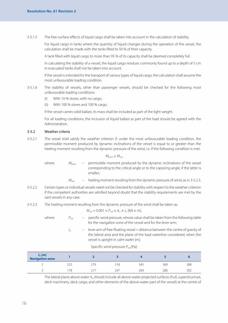
18
Resolution No. 61 Revision 2
3-5.1.5 The free-surface effects of liquid cargo shall be taken into account in the calculation of stability.
For liquid cargo in tanks where the quantity of liquid changes during the operation of the vessel, the calculation shall be made with the tanks filled to 50 % of their capacity.
A tank filled with liquid cargo to more than 95 % of its capacity shall be deemed completely full.
In calculating the stability of a vessel, the liquid cargo residues commonly found up to a depth of 5 cm in evacuated tanks shall not be taken into account.
If the vessel is intended for the transport of various types of liquid cargo, the calculation shall assume the most unfavourable loading condition.
3-5.1.6 The stability of vessels, other than passenger vessels, should be checked for the following most unfavourable loading conditions:
(i) With 10 % stores, with no cargo;
(ii) With 100 % stores and 100 % cargo.
If the vessel carries solid ballast, its mass shall be included as part of the light weight.
For all loading conditions, the inclusion of liquid ballast as part of the load should be agreed with the Administration.
3-5.2 Weather criteria
3-5.2.1 The vessel shall satisfy the weather criterion if, under the most unfavourable loading condition, the permissible moment produced by dynamic inclinations of the vessel is equal to or greater than the heeling moment resulting from the dynamic pressure of the wind, i.e. if the following condition is met:
Mperm ≥ Mwd
where: Mperm – permissible moment produced by the dynamic inclinations of the vessel corresponding to the critical angle or to the capsizing angle, if the latter is smaller;
Mwd – heeling moment resulting from the dynamic pressure of wind, as in 3-5.2.3.
3-5.2.2 Certain types or individual vessels need not be checked for stability with respect to the weather criterion if the competent authorities are satisfied beyond doubt that the stability requirements are met by the said vessels in any case.
3-5.2.3 The heeling moment resulting from the dynamic pressure of the wind shall be taken as:
Mwd = 0.001 × Pwd × Aw × lw [kN × m],
where: Pwd – specific wind pressure, whose value shall be taken from the following table for the navigation zone of the vessel and for the lever arm;
lw – lever arm of free-floating vessel = distance between the centre of gravity of the lateral area and the plane of the load waterline considered, when the vessel is upright in calm water [m].
Specific wind pressure Pwd [Pa]:
lw [m] Navigation zone 1 2 3 4 5 6
2 232 279 318 345 369 388
3 178 217 247 269 286 302
The lateral plane above water Aw should include all above-water projected surfaces (hull, superstructure, deck machinery, deck cargo, and other elements of the above-water part of the vessel) at the centre of
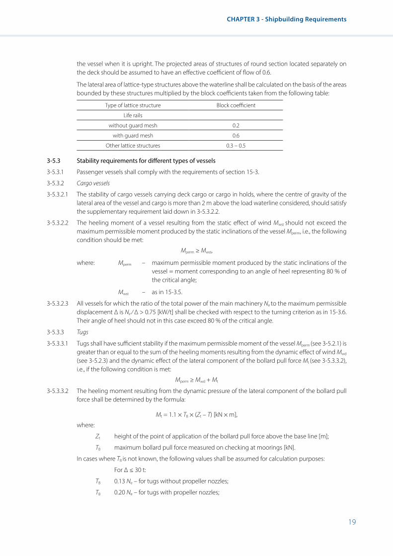
19
CHAPTER 3 - Shipbuilding Requirements
the vessel when it is upright. The projected areas of structures of round section located separately on the deck should be assumed to have an effective coefficient of flow of 0.6.
The lateral area of lattice-type structures above the waterline shall be calculated on the basis of the areas bounded by these structures multiplied by the block coefficients taken from the following table:
Type of lattice structure Block coefficient
Life rails
without guard mesh 0.2
with guard mesh 0.6
Other lattice structures 0.3 – 0.5
3-5.3 Stability requirements for different types of vessels
3-5.3.1 Passenger vessels shall comply with the requirements of section 15-3.
3-5.3.2 Cargo vessels
3-5.3.2.1 The stability of cargo vessels carrying deck cargo or cargo in holds, where the centre of gravity of the lateral area of the vessel and cargo is more than 2 m above the load waterline considered, should satisfy the supplementary requirement laid down in 3-5.3.2.2.
3-5.3.2.2 The heeling moment of a vessel resulting from the static effect of wind Mwst should not exceed the maximum permissible moment produced by the static inclinations of the vessel Mperm, i.e., the following condition should be met:
Mperm ≥ Mwst,
where: Mperm – maximum permissible moment produced by the static inclinations of the vessel = moment corresponding to an angle of heel representing 80 % of the critical angle;
Mwst – as in 15-3.5.
3-5.3.2.3 All vessels for which the ratio of the total power of the main machinery Ne to the maximum permissible displacement Δ is Ne ⁄ ∆ > 0.75 [kW/t] shall be checked with respect to the turning criterion as in 15-3.6. Their angle of heel should not in this case exceed 80 % of the critical angle.
3-5.3.3 Tugs
3-5.3.3.1 Tugs shall have sufficient stability if the maximum permissible moment of the vessel Mperm (see 3-5.2.1) is greater than or equal to the sum of the heeling moments resulting from the dynamic effect of wind Mwd
(see 3-5.2.3) and the dynamic effect of the lateral component of the bollard pull force Mt (see 3-5.3.3.2), i.e., if the following condition is met:
Mperm ≥ Mwd + Mt
3-5.3.3.2 The heeling moment resulting from the dynamic pressure of the lateral component of the bollard pull force shall be determined by the formula:
Mt = 1.1 × TB × (Zt – T) [kN × m],
where:
Zt height of the point of application of the bollard pull force above the base line [m];
TB maximum bollard pull force measured on checking at moorings [kN].
In cases where TB is not known, the following values shall be assumed for calculation purposes:
For Δ ≤ 30 t:
TB 0.13 Ne – for tugs without propeller nozzles;
TB 0.20 Ne – for tugs with propeller nozzles;

20
Resolution No. 61 Revision 2
For Δ ≥ 30 t:
TB 0.16 Ne– for tugs without propeller nozzles;
TB 0.20 Ne – for tugs with propeller nozzles:
Ne the total power of the main machinery [kW].
3-5.3.3.3 In addition to the conditions laid down in 3-5.3.3.1, the stability of each tug should satisfy the following supplementary requirement:
the angle of heel resulting from the combined effect of the heeling moments produced by the dynamic pressure of wind Pwd and the effect of the centrifugal force on turning Mcf (see 15-3.6) should not exceed the critical angle and should in no case exceed 15°.
3-5.4 Supplementary requirements for vessels in navigation zone 1
3-5.4.1 General provisions
3-5.4.1.1 The stability of vessels intended for navigation in zone 1 should satisfy the requirements of sections 3-5.1, 3-5.2 and 3-5.3 for vessels of zone 2, and also the supplementary requirements of this section. Furthermore, the conditions for satisfactory stability laid down in paragraph 3-5.1.2, subparagraphs (i) and (ii) should also be met for the simultaneous rolling of the vessel.
3-5.4.1.2 Compliance with the applicable requirements of the IMO recommendations for sea-going ships may be considered as equivalent to compliance with these recommendations.
3-5.4.1.3 When checking stability with respect to the weather criterion, the heeling moment resulting from the dynamic pressure of wind Mwd shall be calculated taking the specific wind pressure Pwd for navigation zone 2, as in the table at paragraph 3-5.2.3.
3-5.4.1.4 The permissible heeling moment Mperm shall be determined by means of the stability curve, taking into account the value for the amplitude of roll calculated as in 3-5.4.2.
3-5.4.1.5 The critical angle shall be taken to be the angle of heel at which water begins to fill the vessel through unsecured openings in the side plating or on the deck. The maximum angle may not extend further than the upper edge of the side coaming of the cargo hatch or the upper edge of the expansion trunks of tankers.
3-5.4.2 Calculation of the value for the amplitude of roll of a vessel
3-5.4.2.1 The value for the amplitude of roll φm of a flat-bottomed vessel with a bilge radius of 0.05 B or more not fitted with bilge keels shall be determined from the following table in terms of a value m calculated by the formula:
m = 0.66∙m1 × m2 [s-1],
where m1 and m2 - factors determined in accordance with paragraphs 3-5.4.2.2 and 3-5.4.2.3.
m [s-1] 0.40 0.60 0.80 1.00 1.20 1.40 1.60 or more
φm [º] 9 10 13 17 20 23 24
3-5.4.2.2 The factor m1 shall be calculated by the formula: 𝑚𝑚𝑚𝑚1 =
𝑚𝑚𝑚𝑚0
√𝐺𝐺𝐺𝐺𝑀𝑀𝑀𝑀 [s−1]
where: 𝐺𝐺𝐺𝐺𝑀𝑀𝑀𝑀����� – initial metacentric height for the loading condition considered, without correction for the free-surface effects of liquid cargo;
m0 – a value from the following table in relation to the parameter 1n determined by the formula:
𝑛𝑛𝑛𝑛1 =𝐵𝐵𝐵𝐵 ∙ 𝐺𝐺𝐺𝐺𝑀𝑀𝑀𝑀�����
𝐾𝐾𝐾𝐾𝐺𝐺𝐺𝐺 ∙ √∆3
where: KG – see paragraph 15-3.6.
n1 0.1 or less
0.15 0.25 0.50 0.75 1.00 1.50 2.00 2.50 3.0 or more
m0 0.42 0.52 0.78 1.38 1.94 2.40 3.00 3.00 3.50 3.60
3-5.4.2.3 The non-dimensional factor m2 shall be taken from the following table as a function of the ratio B/T.
TB / 2.5 or less
3.0 3.5 4.0 5.0 6.0 7.0 8.0 9.0 10 or more
2m 1.0 0.9 0.81 0.78 0.81 0.87 0.92 0.96 0.99 1.0
3-5.4.2.4 In cases where the bilge radius is less than 0.05 B , the value for the amplitude of roll determined in accordance with paragraph 3-5.4.2.1 may be reduced to a value of φ determined by the formula:
φ = φm× �0.75 + 5𝑝𝑝𝑝𝑝𝐵𝐵𝐵𝐵� [degrees],
where: r – bilge radius [m].
3-5.4.2.5 The amplitude of roll φm determined in accordance with paragraph 3-5.4.2.1 shall be taken into account in the stability curve (see sketches 3-5.4.2.5.1 (a) and (b) and 3-5.4.2.5.2 (a) and (b)).
where: GM – initial metacentric height for the loading condition considered, without correction for the free-surface effects of liquid cargo;
m0 – a value from the following table in relation to the parameter n1 determined by the formula:
𝑚𝑚𝑚𝑚1 =
𝑚𝑚𝑚𝑚0
√𝐺𝐺𝐺𝐺𝑀𝑀𝑀𝑀 [s−1]
where: 𝐺𝐺𝐺𝐺𝑀𝑀𝑀𝑀����� – initial metacentric height for the loading condition considered, without correction for the free-surface effects of liquid cargo;
m0 – a value from the following table in relation to the parameter 1n determined by the formula:
𝑛𝑛𝑛𝑛1 =𝐵𝐵𝐵𝐵 ∙ 𝐺𝐺𝐺𝐺𝑀𝑀𝑀𝑀�����
𝐾𝐾𝐾𝐾𝐺𝐺𝐺𝐺 ∙ √∆3
where: KG – see paragraph 15-3.6.
n1 0.1 or less
0.15 0.25 0.50 0.75 1.00 1.50 2.00 2.50 3.0 or more
m0 0.42 0.52 0.78 1.38 1.94 2.40 3.00 3.00 3.50 3.60
3-5.4.2.3 The non-dimensional factor m2 shall be taken from the following table as a function of the ratio B/T.
TB / 2.5 or less
3.0 3.5 4.0 5.0 6.0 7.0 8.0 9.0 10 or more
2m 1.0 0.9 0.81 0.78 0.81 0.87 0.92 0.96 0.99 1.0
3-5.4.2.4 In cases where the bilge radius is less than 0.05 B , the value for the amplitude of roll determined in accordance with paragraph 3-5.4.2.1 may be reduced to a value of φ determined by the formula:
φ = φm× �0.75 + 5𝑝𝑝𝑝𝑝𝐵𝐵𝐵𝐵� [degrees],
where: r – bilge radius [m].
3-5.4.2.5 The amplitude of roll φm determined in accordance with paragraph 3-5.4.2.1 shall be taken into account in the stability curve (see sketches 3-5.4.2.5.1 (a) and (b) and 3-5.4.2.5.2 (a) and (b)).
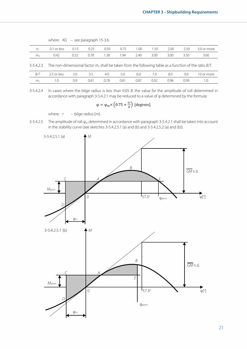
21
CHAPTER 3 - Shipbuilding Requirements
where: KG – see paragraph 15-3.6.
n1 0.1 or less 0.15 0.25 0.50 0.75 1.00 1.50 2.00 2.50 3.0 or more
m0 0.42 0.52 0.78 1.38 1.94 2.40 3.00 3.00 3.50 3.60
3-5.4.2.3 The non-dimensional factor m2 shall be taken from the following table as a function of the ratio B/T.
B/T 2.5 or less 3.0 3.5 4.0 5.0 6.0 7.0 8.0 9.0 10 or more
m2 1.0 0.9 0.81 0.78 0.81 0.87 0.92 0.96 0.99 1.0
3-5.4.2.4 In cases where the bilge radius is less than 0.05 B, the value for the amplitude of roll determined in accordance with paragraph 3-5.4.2.1 may be reduced to a value of φ determined by the formula:
𝑚𝑚𝑚𝑚1 =
𝑚𝑚𝑚𝑚0
√𝐺𝐺𝐺𝐺𝑀𝑀𝑀𝑀 [s−1]
where: 𝐺𝐺𝐺𝐺𝑀𝑀𝑀𝑀����� – initial metacentric height for the loading condition considered, without correction for the free-surface effects of liquid cargo;
m0 – a value from the following table in relation to the parameter 1n determined by the formula:
𝑛𝑛𝑛𝑛1 =𝐵𝐵𝐵𝐵 ∙ 𝐺𝐺𝐺𝐺𝑀𝑀𝑀𝑀�����
𝐾𝐾𝐾𝐾𝐺𝐺𝐺𝐺 ∙ √∆3
where: KG – see paragraph 15-3.6.
n1 0.1 or less
0.15 0.25 0.50 0.75 1.00 1.50 2.00 2.50 3.0 or more
m0 0.42 0.52 0.78 1.38 1.94 2.40 3.00 3.00 3.50 3.60
3-5.4.2.3 The non-dimensional factor m2 shall be taken from the following table as a function of the ratio B/T.
TB / 2.5 or less
3.0 3.5 4.0 5.0 6.0 7.0 8.0 9.0 10 or more
2m 1.0 0.9 0.81 0.78 0.81 0.87 0.92 0.96 0.99 1.0
3-5.4.2.4 In cases where the bilge radius is less than 0.05 B , the value for the amplitude of roll determined in accordance with paragraph 3-5.4.2.1 may be reduced to a value of φ determined by the formula:
φ = φm× �0.75 + 5𝑝𝑝𝑝𝑝𝐵𝐵𝐵𝐵� [degrees],
where: r – bilge radius [m].
3-5.4.2.5 The amplitude of roll φm determined in accordance with paragraph 3-5.4.2.1 shall be taken into account in the stability curve (see sketches 3-5.4.2.5.1 (a) and (b) and 3-5.4.2.5.2 (a) and (b)).
where: r – bilge radius [m].
3-5.4.2.5 The amplitude of roll φm determined in accordance with paragraph 3-5.4.2.1 shall be taken into account in the stability curve (see sketches 3-5.4.2.5.1 (a) and (b) and 3-5.4.2.5.2 (a) and (b)).
M
A
B
EC
Mperm
D
0 57.3oφperm
GM x ∆
φ[o]
3-5.4.2.5.1 (a)
φm
M
A
B
EC
Mperm
D
0 57.3o
φperm
GM x ∆
φ[o]
3-5.4.2.5.1 (b)
φm
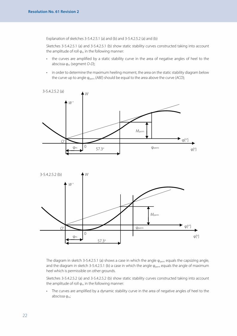
22
Resolution No. 61 Revision 2
Explanation of sketches 3-5.4.2.5.1 (a) and (b) and 3-5.4.2.5.2 (a) and (b)
Sketches 3-5.4.2.5.1 (a) and 3-5.4.2.5.1 (b) show static stability curves constructed taking into account the amplitude of roll φm in the following manner:
• the curves are amplified by a static stability curve in the area of negative angles of heel to the abscissa φm (segment O-D);
• in order to determine the maximum heeling moment, the area on the static stability diagram below the curve up to angle φperm (ABE) should be equal to the area above the curve (ACD);
W
Mperm
57.3o φperm φ[o]
W ‘
φ[o’]O‘φm 0
3-5.4.2.5.2 (a)
W
Mperm
57.3o
φperm
φ[o]
W ‘
φ[o’]O‘
φm0
3-5.4.2.5.2 (b)
The diagram in sketch 3-5.4.2.5.1 (a) shows a case in which the angle φperm equals the capsizing angle, and the diagram in sketch 3-5.4.2.5.1 (b) a case in which the angle φperm equals the angle of maximum heel which is permissible on other grounds.
Sketches 3-5.4.2.5.2 (a) and 3-5.4.2.5.2 (b) show static stability curves constructed taking into account the amplitude of roll φm in the following manner:
• The curves are amplified by a dynamic stability curve in the area of negative angles of heel to the abscissa φm;

23
CHAPTER 3 - Shipbuilding Requirements
• A tangent to the dynamic stability curve is produced through new origin O’ in order to determine the maximum capsizing moment φperm (see sketch 3-5.4.2.5.2 (a)), or a straight line is produced through the point of intersection of the dynamic stability curve with a vertical straight line drawn from the point of the angle of heel φperm which is permissible on other grounds;
• The segment at an angle of 1 radian gives the value of the maximum permissible heeling moment.
3-6 Other provisions
3-6.1 The fore sections of vessels shall be built in such a way that the anchors neither wholly nor partly protrude beyond the hull plating. The Basin Administration may accept other arrangemens as regards to stowage of the raised anchors as an equivalent safety level has been proved.


25
CHAPTER 3A - Fire Protection
CHAPTER 3A - Fire Protection
3A-1 Structural requirements
3A-1.1 The hull, superstructures, structural bulkheads, decks and deckhouses shall be made of steel. The Administration or a recognized Classification Society may allow the use of other materials with due regard to the risk of fire.
On vessels with a length of 85 m or more and intended for navigation in zone 1, in accommodation spaces, the corridor bulkheads shall be made of steel or other materials approved by the Administration or recognized Classification Society with due regard to the risk of fire.
3A-1.2 Crew elevator trunks within accommodation and interior stairways below the open deck shall be made of steel or equivalent material.
3A-1.3 The bulkheads of galleys, paint stores, lamprooms, boatswain’s stores (when adjacent to accommodation spaces) and emergency generator rooms, if any, shall be made of steel or equivalent material.
3A-1.4 Deck, bulkhead and ceiling coverings within accommodation spaces shall be made of flame-retardant materials. They shall be made of fire resistant materials when they form part of an escape route or a partition between the accommodation space and machinery spaces or store rooms. The furniture in the above-mentioned accommodation spaces shall be made of a material which will not easily catch fire. In the case of fire or heating the materials shall not release toxic or explosive gases in dangerous concentrations.
3A-1.5 Bulkheads, ceilings and doors of machinery spaces and boiler rooms shall be made of steel or other equally fire-resistant material.
Stairways and ladders leading to machinery spaces and boiler rooms shall be fixed permanently and made of steel or equivalent material.
3A-1.6 Paints, varnishes and similar products having a nitro-cellulose or other highly inflammable base shall not be used for the interior furnishings in a vessel’s spaces.
3A-1.7 Tanks and their pipelines as well as other accessories shall be laid out and arranged with due regard to the risk of fire and in such a way that no fuel or gas can escape accidentally into the vessel. Tank valves intended for fuel sampling or water drainage shall close automatically. Materials with a low resistance to heat shall not be used for overboard scuppers, sanitary discharges or other outlets which are close to the water line, or in places where failure of the material in the event of fire might cause flooding.
3A-1.8 At tank outlets the pipelines for the distribution of liquid fuels shall be fitted with a shutoff device that can be operated from the deck.
3A-1.9 Electric radiators shall be so designed and fixed in position as to reduce fire risks to a minimum.
3A-1.10 Forced ventilation of machinery spaces shall be capable of being stopped from an easily accessible position outside the machinery spaces.
3A-1.11 Automatic devices for detecting and signalling about smoke or heat, which indicate fire on board, shall satisfy the requirements of the Administration or recognized Classification Society.
3A-2 Means of escape
3A-2.1 In all crew spaces and spaces in which crew members are normally employed, stairways and ladders shall be so installed as to provide a ready means of escape to an open deck.
3A-2.2 Living and sleeping quarters shall have at least two exits as far apart from each other as possible which serve as escape routes. One of them may be designed as an emergency exit. This does not apply to areas with an exit giving directly onto the deck or into a corridor which serves as an escape route, provided
26
Resolution No. 61 Revision 2
the corridor has two exits at a distance from each other and giving onto port and starboard. Emergency exits, which may include skylights and windows, shall have a clear opening of at least 0.36 m² with a smallest side of at least 0.50 m and permit rapid evacuation in an emergency.
3A-2.3 Engine and boiler rooms shall have two exits of which one may be an emergency exit.
The second exit may be dispensed with if:
(i) The total floor area (average length × average width) of the engine or boiler room does not exceed 35 m2; and
(ii) The distance between each point where service or maintenance operations are to be carried out and the exit, or foot of the stairway near the exit providing access to the outside, is not longer than 5 m; and
(iii) A fire extinguisher is placed at the maintenance station that is furthest removed from the exit door.
3A-3 Storage of flammable liquids
To store flammable liquids with a flash point of less than 55ºC there shall be a ventilated cupboard made of non-combustible material on deck. On its outside there shall be a symbol “No naked lights or fires and no smoking” in accordance with sketch 2 of appendix 3 and with a diameter of at least 10 cm.
27
CHAPTER 4 - Safety Clearance, Freeboard and Draught Marks
CHAPTER 4 - Safety Clearance, Freeboard and Draught Marks
4-1 General4-1.1 This chapter specifies the minimum freeboard for inland waterway vessels. It also contains requirements
concerning the indication of the freeboard mark and draught marks.
4-1.2 This chapter assumes that the nature and stowage of the cargo, ballast, etc., are such as to ensure adequate stability and as to obviate any excessive structural fatigue.
4-1.3 Freeboards as prescribed in this chapter shall be assigned on the assumption, first, that navigation will cease when weather conditions are such that the maximum wave height defining the zone or zones in which a vessel is to navigate may be exceeded, and second that in such conditions vessels already under way will seek shelter as quickly as possible.
4-1.4 The Administration may consider it sufficient if the vessel has been built and maintained in conformity with the rules of a recognized Classification Society.
4-2 Types of vessels
For the purpose of this chapter, vessels shall be divided into three types:
(i) Decked vessels;
(ii) Tankers;
(iii) Open vessels.
Decked vessels: Decked vessels are vessels whose hatch covers are satisfactorily strong, rigid, watertight for zone 1 and spray proof for zones 2 and 3.
Tankers and similar vessels: These vessels have only small openings giving access to the tanks, the openings being closed by steel or equivalent covers with watertight fittings. Such vessels have the following characteristics:
(i) Very high watertight integrity of the exposed deck;
(ii) Very high resistance to flooding, through low permeability of the loaded compartments and through the degree of subdivision applied in general.
Open vessels: Open vessels are either vessels whose hatch covers are not satisfactorily strong, rigid, spray-proof or vessels whose cargo hatchways are open.
4-3 Draught marks and freeboard mark4-3.1 The plane of maximum draught shall be determined in such a way that the specifications concerning
minimum freeboard and minimum safety clearance are both met. However, for safety reasons, the competent authority may lay down a greater value for the safety clearance o freeboard. The plane of maximum draught shall be determined at least for zone 3.
4-3.2 The plane of maximum draught shall be indicated by means of highly visible, indelible draught marks.
4-3.3 Vessels shall have at least three pairs of draught marks, of which one pair shall be centrally located and the two others located, respectively, at a distance from the bow and stern that is equal to roughly one-sixth of the length.
However,
(i) Where a vessel is less than 40 m in length it will suffice to affix two pairs of marks at a distance from the bow and stern, respectively, that is equal to a quarter of the length;
(ii) Where vessels are not intended for the carriage of goods, a pair of marks located roughly halfway along the vessel will suffice.

28
Resolution No. 61 Revision 2
4-3.4 The draught marks for zone 3 shall consist of a rectangle 300 mm long and 40 mm deep, the base of which is horizontal and coincides with the plane of the maximum authorized draught. Any differing draught marks shall include such a rectangle.
4-3.5 Marks or indications which cease to be valid following a further inspection shall be deleted or marked as being no longer valid under the supervision of the Administration. Draught marks may only be replaced under the supervision of the Administration.
4-3.6 Where a vessel has been measured in implementation of the 1966 Convention on the Measurement of Inland Navigation Vessels and the plane of the measurement marks meets the requirements of this resolution, those measurement marks shall take the place of the draught marks; this shall be mentioned in the ship’s certificate.
4-3.7 For vessels operating on zones of inland waterways other than zone 3 (zones 1, 2 or 4) the bow and stern pairs of draught marks provided for in 4.3.3 shall be supplemented by adding a vertical line to which one or, in the case of several zones, several additional draught lines 150 mm long shall be affixed towards the bow, in relation to the draught mark for zone 3.
This vertical line and the horizontal line shall be 30 mm thick. In addition to the draught mark towards the bow of the vessel, the relevant zone numbers shall be indicated in lettering 60 mm high × 40 mm deep (see figure 4-3.7).
The lower edge of each draught line shall correspond to the plane of maximum authorised draught for the navigation zone concerned.
Figure 4-3.7 Measurement/draught scale
4-3.8 The centrally located measurement/draught scale for zones 1 and 2 may be replaced by a freeboard mark.
The freeboard mark consists of a ring intersected through its centre by a horizontal line which shall be supplemented if necessary by additional freeboard lines.
30
300 150
2
2
1
4
4
2
100
3030
40
Measurement mark
Freeboard deck
Plane of maximum draught for zone 3
Draught mark
Measurement scale 1
2
4
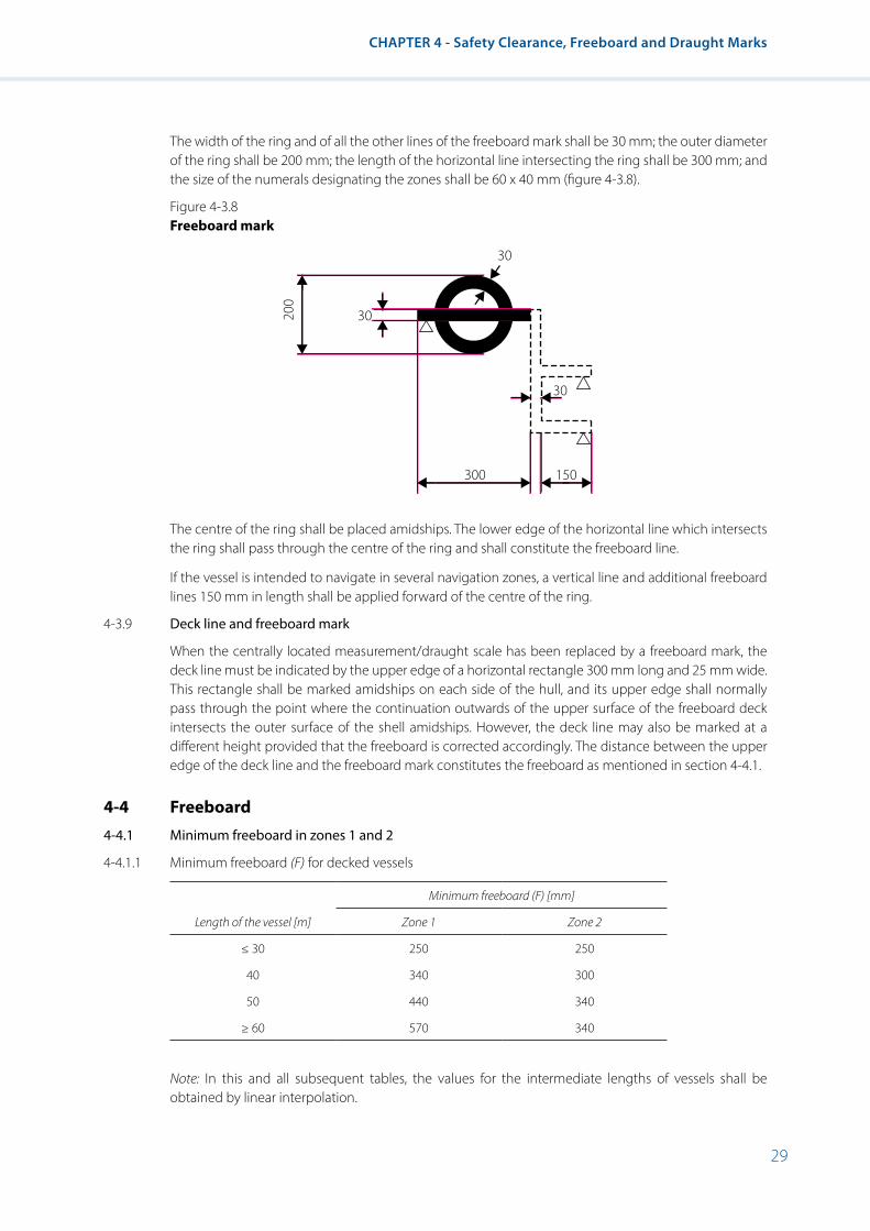
29
CHAPTER 4 - Safety Clearance, Freeboard and Draught Marks
The width of the ring and of all the other lines of the freeboard mark shall be 30 mm; the outer diameter of the ring shall be 200 mm; the length of the horizontal line intersecting the ring shall be 300 mm; and the size of the numerals designating the zones shall be 60 x 40 mm (figure 4-3.8).
Figure 4-3.8 Freeboard mark
The centre of the ring shall be placed amidships. The lower edge of the horizontal line which intersects the ring shall pass through the centre of the ring and shall constitute the freeboard line.
If the vessel is intended to navigate in several navigation zones, a vertical line and additional freeboard lines 150 mm in length shall be applied forward of the centre of the ring.
4-3.9 Deck line and freeboard mark
When the centrally located measurement/draught scale has been replaced by a freeboard mark, the deck line must be indicated by the upper edge of a horizontal rectangle 300 mm long and 25 mm wide. This rectangle shall be marked amidships on each side of the hull, and its upper edge shall normally pass through the point where the continuation outwards of the upper surface of the freeboard deck intersects the outer surface of the shell amidships. However, the deck line may also be marked at a different height provided that the freeboard is corrected accordingly. The distance between the upper edge of the deck line and the freeboard mark constitutes the freeboard as mentioned in section 4-4.1.
4-4 Freeboard
4-4.1 Minimum freeboard in zones 1 and 2
4-4.1.1 Minimum freeboard (F) for decked vessels
Length of the vessel [m]
Minimum freeboard (F) [mm]
Zone 1 Zone 2
≤ 30 250 250
40 340 300
50 440 340
≥ 60 570 340
Note: In this and all subsequent tables, the values for the intermediate lengths of vessels shall be obtained by linear interpolation.
30200
30
300 150
30
30
Resolution No. 61 Revision 2
4-4.1.2 Minimum freeboard (F) for tankers and flush deck vessels
Length of the vessel [m]
Minimum freeboard (F) [mm]
Zone 1 Zone 2
≤ 30 180 160
40 250 220
50 330 220
≥ 60 420 220
4-4.1.3 The minimum freeboard for open vessels should be not less than: For zone 1 – 1,000 mm, zone 2 – 600 mm.
Furthermore, the sum of the freeboard and the height of coamings for these vessels must be not less than:
For zone 1 – 1,200 mm, zone 2 – 1,000 mm.
4-4.1.4 The Administration may authorize corrections for the freeboard for vessels with poop, sheer and forecastle, providing that such corrections are calculated in conformity with the rules of the Administration or of a recognized Classification Society.
4-4.2 Minimum freeboard in zone 3
4-4.2.1 The basic freeboard of vessels with a continuous deck without superstructures and sheer shall be 150 mm.
4-4.2.2 The freeboard of vessels with sheer and superstructures shall be calculated using the following formula:
𝐹𝐹𝐹𝐹 = 150 (1 − α) − βv×𝑆𝑆𝑆𝑆ev+ βa×𝑆𝑆𝑆𝑆ea15
[mm],
where: α – correction coefficient that takes account of all of the superstructures involved; βv – coefficient for correcting the effect of the forward sheer resulting from the presence of superstructures in the forward quarter of length L of the vessel; βa – coefficient correcting the effect of the aft sheer resulting from the presence of superstructures in the aft quarter of length L of the vessel; 𝑆𝑆𝑆𝑆ev – effective forward sheer, [mm];
𝑆𝑆𝑆𝑆ea – effective aft sheer, [mm].
4-4.2.3 The coefficient α is calculated using the following formula:
α = ∑ 𝑙𝑙𝑙𝑙ea+∑ 𝑙𝑙𝑙𝑙em+∑ 𝑙𝑙𝑙𝑙ev
𝐿𝐿𝐿𝐿 ,
where: 𝑙𝑙𝑙𝑙ea – effective length, of a superstructure in the aft quarter of the vessel length L, [m]; 𝑙𝑙𝑙𝑙em – effective length of a superstructure located in the median part corresponding to one half of length L of the vessel, [m]; 𝑙𝑙𝑙𝑙ev – effective length of a superstructure in the forward quarter of the vessel length L, [m]. The effective length of a superstructure is calculated using the following formulae:
𝑙𝑙𝑙𝑙em = 1 �2.5×𝑏𝑏𝑏𝑏𝐵𝐵𝐵𝐵− 1.5�×
ℎ0.36
[m]
𝑙𝑙𝑙𝑙ev , 𝑙𝑙𝑙𝑙ea = 1× �2.5×𝑏𝑏𝑏𝑏𝐵𝐵𝐵𝐵1
− 1.5�×ℎ
0.36 [m],
where: l – effective length of the superstructure involved, , [m]; b – width of the superstructure involved, [m]; В1 – width of the vessel, measured on the outside of the vertical sideplates at deck level halfway along the superstructure involved, [m]; h – height of the superstructure involved, [m]. However, in the case of hatches, h is obtained by reducing the height of the coamings by half of the safety distance according to 4-5.2 and 4-5.3. In no case will a value exceeding 0.36 m be taken for h.
where: α – correction coefficient that takes account of all of the superstructures involved; βv – coefficient for correcting the effect of the forward sheer resulting from the presence
of superstructures in the forward quarter of length L of the vessel; βa – coefficient correcting the effect of the aft sheer resulting from the presence of
superstructures in the aft quarter of length L of the vessel; Sev – effective forward sheer, [mm]; Sea – effective aft sheer, [mm].
4-4.2.3 The coefficient α is calculated using the following formula:
For zone 1 – 1,200 mm, zone 2 – 1,000 mm.
4-4.1.4 The Administration may authorize corrections for the freeboard for vessels with poop, sheer and forecastle, providing that such corrections are calculated in conformity with the rules of the Administration or of a recognized Classification Society.
4-4.2 Minimum freeboard in zone 3
4-4.2.1 The basic freeboard of vessels with a continuous deck without superstructures and sheer shall be 150 mm.
4-4.2.2 The freeboard of vessels with sheer and superstructures shall be calculated using the following formula:
𝐹𝐹𝐹𝐹 = 150 (1 − α) − βv×𝑆𝑆𝑆𝑆ev+ βa×𝑆𝑆𝑆𝑆ea15
[mm],
where: α – correction coefficient that takes account of all of the superstructures involved; βv – coefficient for correcting the effect of the forward sheer resulting from the presence of superstructures in the forward quarter of length L of the vessel; βa – coefficient correcting the effect of the aft sheer resulting from the presence of superstructures in the aft quarter of length L of the vessel; 𝑆𝑆𝑆𝑆ev – effective forward sheer, [mm];
𝑆𝑆𝑆𝑆ea – effective aft sheer, [mm].
4-4.2.3 The coefficient α is calculated using the following formula:
α = ∑ 𝑙𝑙𝑙𝑙ea+∑ 𝑙𝑙𝑙𝑙em+∑ 𝑙𝑙𝑙𝑙ev
𝐿𝐿𝐿𝐿 ,
where: 𝑙𝑙𝑙𝑙ea – effective length, of a superstructure in the aft quarter of the vessel length L, [m]; 𝑙𝑙𝑙𝑙em – effective length of a superstructure located in the median part corresponding to one half of length L of the vessel, [m]; 𝑙𝑙𝑙𝑙ev – effective length of a superstructure in the forward quarter of the vessel length L, [m]. The effective length of a superstructure is calculated using the following formulae:
𝑙𝑙𝑙𝑙em = 1 �2.5×𝑏𝑏𝑏𝑏𝐵𝐵𝐵𝐵− 1.5�×
ℎ0.36
[m]
𝑙𝑙𝑙𝑙ev , 𝑙𝑙𝑙𝑙ea = 1× �2.5×𝑏𝑏𝑏𝑏𝐵𝐵𝐵𝐵1
− 1.5�×ℎ
0.36 [m],
where: l – effective length of the superstructure involved, , [m]; b – width of the superstructure involved, [m]; В1 – width of the vessel, measured on the outside of the vertical sideplates at deck level halfway along the superstructure involved, [m]; h – height of the superstructure involved, [m]. However, in the case of hatches, h is obtained by reducing the height of the coamings by half of the safety distance according to 4-5.2 and 4-5.3. In no case will a value exceeding 0.36 m be taken for h.
where: lea – effective length, of a superstructure in the aft quarter of the vessel length L, [m] lem – effective length of a superstructure located in the median part corresponding to
one half of length L of the vessel, [m]; lev – effective length of a superstructure in the forward quarter of the vessel length L, [m].
The effective length of a superstructure is calculated using the following formulae:
For zone 1 – 1,200 mm, zone 2 – 1,000 mm.
4-4.1.4 The Administration may authorize corrections for the freeboard for vessels with poop, sheer and forecastle, providing that such corrections are calculated in conformity with the rules of the Administration or of a recognized Classification Society.
4-4.2 Minimum freeboard in zone 3
4-4.2.1 The basic freeboard of vessels with a continuous deck without superstructures and sheer shall be 150 mm.
4-4.2.2 The freeboard of vessels with sheer and superstructures shall be calculated using the following formula:
𝐹𝐹𝐹𝐹 = 150 (1 − α) − βv×𝑆𝑆𝑆𝑆ev+ βa×𝑆𝑆𝑆𝑆ea15
[mm],
where: α – correction coefficient that takes account of all of the superstructures involved; βv – coefficient for correcting the effect of the forward sheer resulting from the presence of superstructures in the forward quarter of length L of the vessel; βa – coefficient correcting the effect of the aft sheer resulting from the presence of superstructures in the aft quarter of length L of the vessel; 𝑆𝑆𝑆𝑆ev – effective forward sheer, [mm];
𝑆𝑆𝑆𝑆ea – effective aft sheer, [mm].
4-4.2.3 The coefficient α is calculated using the following formula:
α = ∑ 𝑙𝑙𝑙𝑙ea+∑ 𝑙𝑙𝑙𝑙em+∑ 𝑙𝑙𝑙𝑙ev
𝐿𝐿𝐿𝐿 ,
where: 𝑙𝑙𝑙𝑙ea – effective length, of a superstructure in the aft quarter of the vessel length L, [m]; 𝑙𝑙𝑙𝑙em – effective length of a superstructure located in the median part corresponding to one half of length L of the vessel, [m]; 𝑙𝑙𝑙𝑙ev – effective length of a superstructure in the forward quarter of the vessel length L, [m]. The effective length of a superstructure is calculated using the following formulae:
𝑙𝑙𝑙𝑙em = 1 �2.5×𝑏𝑏𝑏𝑏𝐵𝐵𝐵𝐵− 1.5�×
ℎ0.36
[m]
𝑙𝑙𝑙𝑙ev , 𝑙𝑙𝑙𝑙ea = 1× �2.5×𝑏𝑏𝑏𝑏𝐵𝐵𝐵𝐵1
− 1.5�×ℎ
0.36 [m],
where: l – effective length of the superstructure involved, , [m]; b – width of the superstructure involved, [m]; В1 – width of the vessel, measured on the outside of the vertical sideplates at deck level halfway along the superstructure involved, [m]; h – height of the superstructure involved, [m]. However, in the case of hatches, h is obtained by reducing the height of the coamings by half of the safety distance according to 4-5.2 and 4-5.3. In no case will a value exceeding 0.36 m be taken for h.

31
CHAPTER 4 - Safety Clearance, Freeboard and Draught Marks
where: l – effective length of the superstructure involved, [m]; b – width of the superstructure involved, [m]; В1 – width of the vessel, measured on the outside of the vertical sideplates at deck level halfway along the superstructure involved, [m]; h – height of the superstructure involved, [m]. However, in the case of hatches, h is
obtained by reducing the height of the coamings by half of the safety distance according to 4-5.2 and 4-5.3. In no case will a value exceeding 0.36 m be taken for h.
If 𝑏𝑏𝑏𝑏
𝐵𝐵𝐵𝐵 or 𝑏𝑏𝑏𝑏
𝐵𝐵𝐵𝐵1 is less than 0.6, the effective length le of the superstructure will be zero.
4-4.2.4 Coefficients βv and βa are calculated using the following formulae:
βv = 1 − 3×𝑙𝑙𝑙𝑙ev𝐿𝐿𝐿𝐿
,
βa = 1 − 3×𝑙𝑙𝑙𝑙ea𝐿𝐿𝐿𝐿
.
4-4.2.5 The effective aft/forward sheers 𝑆𝑆𝑆𝑆ev/𝑆𝑆𝑆𝑆ea are calculated using the following formulae:
𝑆𝑆𝑆𝑆ev = 𝑆𝑆𝑆𝑆v ∙ 𝑝𝑝𝑝𝑝, 𝑆𝑆𝑆𝑆ea = 𝑆𝑆𝑆𝑆a ∙ 𝑝𝑝𝑝𝑝
where: Sv – the actual forward sheer, in mm; however Sv shall not be taken to be more than 1,000 mm; Sa – the actual aft sheer, in mm; however Sa may not be taken to be more than 500 mm; p – a coefficient calculated using the following formula:
𝑝𝑝𝑝𝑝 = 4×𝑥𝑥𝑥𝑥𝐿𝐿𝐿𝐿
x – the abscissa, measured from the extremity of the point where the sheer is 0.25 Sv or 0.25 Sa (see figure 4-3.9).
Figure 4-3.9
However, coefficient p will not be taken to be more than 1.
4-4.2.6 If βa×𝑆𝑆𝑆𝑆ea is greater than βv×𝑆𝑆𝑆𝑆ev , the value of βa×𝑆𝑆𝑆𝑆ea will be taken as being the value for βv×𝑆𝑆𝑆𝑆ev .
4-4.2.7 In view of the reductions referred to in 4-4.2.2 – 4-4.2.6 the minimum freeboard shall not be less than 0 mm.
4-5 SAFETY CLEARANCE
is less than 0.6, the effective length le of the superstructure will be zero.
4-4.2.4 Coefficients βv and βa are calculated using the following formulae:
If 𝑏𝑏𝑏𝑏
𝐵𝐵𝐵𝐵 or 𝑏𝑏𝑏𝑏
𝐵𝐵𝐵𝐵1 is less than 0.6, the effective length le of the superstructure will be zero.
4-4.2.4 Coefficients βv and βa are calculated using the following formulae:
βv = 1 − 3×𝑙𝑙𝑙𝑙ev𝐿𝐿𝐿𝐿
,
βa = 1 − 3×𝑙𝑙𝑙𝑙ea𝐿𝐿𝐿𝐿
.
4-4.2.5 The effective aft/forward sheers 𝑆𝑆𝑆𝑆ev/𝑆𝑆𝑆𝑆ea are calculated using the following formulae:
𝑆𝑆𝑆𝑆ev = 𝑆𝑆𝑆𝑆v ∙ 𝑝𝑝𝑝𝑝, 𝑆𝑆𝑆𝑆ea = 𝑆𝑆𝑆𝑆a ∙ 𝑝𝑝𝑝𝑝
where: Sv – the actual forward sheer, in mm; however Sv shall not be taken to be more than 1,000 mm; Sa – the actual aft sheer, in mm; however Sa may not be taken to be more than 500 mm; p – a coefficient calculated using the following formula:
𝑝𝑝𝑝𝑝 = 4×𝑥𝑥𝑥𝑥𝐿𝐿𝐿𝐿
x – the abscissa, measured from the extremity of the point where the sheer is 0.25 Sv or 0.25 Sa (see figure 4-3.9).
Figure 4-3.9
However, coefficient p will not be taken to be more than 1.
4-4.2.6 If βa×𝑆𝑆𝑆𝑆ea is greater than βv×𝑆𝑆𝑆𝑆ev , the value of βa×𝑆𝑆𝑆𝑆ea will be taken as being the value for βv×𝑆𝑆𝑆𝑆ev .
4-4.2.7 In view of the reductions referred to in 4-4.2.2 – 4-4.2.6 the minimum freeboard shall not be less than 0 mm.
4-5 SAFETY CLEARANCE
4-4.2.5 The effective aft/forward sheers Sev / Sea are calculated using the following formulae:
If 𝑏𝑏𝑏𝑏
𝐵𝐵𝐵𝐵 or 𝑏𝑏𝑏𝑏
𝐵𝐵𝐵𝐵1 is less than 0.6, the effective length le of the superstructure will be zero.
4-4.2.4 Coefficients βv and βa are calculated using the following formulae:
βv = 1 − 3×𝑙𝑙𝑙𝑙ev𝐿𝐿𝐿𝐿
,
βa = 1 − 3×𝑙𝑙𝑙𝑙ea𝐿𝐿𝐿𝐿
.
4-4.2.5 The effective aft/forward sheers 𝑆𝑆𝑆𝑆ev/𝑆𝑆𝑆𝑆ea are calculated using the following formulae:
𝑆𝑆𝑆𝑆ev = 𝑆𝑆𝑆𝑆v ∙ 𝑝𝑝𝑝𝑝, 𝑆𝑆𝑆𝑆ea = 𝑆𝑆𝑆𝑆a ∙ 𝑝𝑝𝑝𝑝
where: Sv – the actual forward sheer, in mm; however Sv shall not be taken to be more than 1,000 mm; Sa – the actual aft sheer, in mm; however Sa may not be taken to be more than 500 mm; p – a coefficient calculated using the following formula:
𝑝𝑝𝑝𝑝 = 4×𝑥𝑥𝑥𝑥𝐿𝐿𝐿𝐿
x – the abscissa, measured from the extremity of the point where the sheer is 0.25 Sv or 0.25 Sa (see figure 4-3.9).
Figure 4-3.9
However, coefficient p will not be taken to be more than 1.
4-4.2.6 If βa×𝑆𝑆𝑆𝑆ea is greater than βv×𝑆𝑆𝑆𝑆ev , the value of βa×𝑆𝑆𝑆𝑆ea will be taken as being the value for βv×𝑆𝑆𝑆𝑆ev .
4-4.2.7 In view of the reductions referred to in 4-4.2.2 – 4-4.2.6 the minimum freeboard shall not be less than 0 mm.
4-5 SAFETY CLEARANCE
where: Sv – the actual forward sheer, in mm; however Sv shall not be taken to be more than 1,000 mm;
Sa – the actual aft sheer, in mm; however Sa may not be taken to be more than 500 mm; p – a coefficient calculated using the following formula:
If 𝑏𝑏𝑏𝑏
𝐵𝐵𝐵𝐵 or 𝑏𝑏𝑏𝑏
𝐵𝐵𝐵𝐵1 is less than 0.6, the effective length le of the superstructure will be zero.
4-4.2.4 Coefficients βv and βa are calculated using the following formulae:
βv = 1 − 3×𝑙𝑙𝑙𝑙ev𝐿𝐿𝐿𝐿
,
βa = 1 − 3×𝑙𝑙𝑙𝑙ea𝐿𝐿𝐿𝐿
.
4-4.2.5 The effective aft/forward sheers 𝑆𝑆𝑆𝑆ev/𝑆𝑆𝑆𝑆ea are calculated using the following formulae:
𝑆𝑆𝑆𝑆ev = 𝑆𝑆𝑆𝑆v ∙ 𝑝𝑝𝑝𝑝, 𝑆𝑆𝑆𝑆ea = 𝑆𝑆𝑆𝑆a ∙ 𝑝𝑝𝑝𝑝
where: Sv – the actual forward sheer, in mm; however Sv shall not be taken to be more than 1,000 mm; Sa – the actual aft sheer, in mm; however Sa may not be taken to be more than 500 mm; p – a coefficient calculated using the following formula:
𝑝𝑝𝑝𝑝 = 4×𝑥𝑥𝑥𝑥𝐿𝐿𝐿𝐿
x – the abscissa, measured from the extremity of the point where the sheer is 0.25 Sv or 0.25 Sa (see figure 4-3.9).
Figure 4-3.9
However, coefficient p will not be taken to be more than 1.
4-4.2.6 If βa×𝑆𝑆𝑆𝑆ea is greater than βv×𝑆𝑆𝑆𝑆ev , the value of βa×𝑆𝑆𝑆𝑆ea will be taken as being the value for βv×𝑆𝑆𝑆𝑆ev .
4-4.2.7 In view of the reductions referred to in 4-4.2.2 – 4-4.2.6 the minimum freeboard shall not be less than 0 mm.
4-5 SAFETY CLEARANCE
x – the abscissa, measured from the extremity of the point where the sheer is 0.25 Sv or 0.25 Sa (see figure 4-3.9).
Figure 4-3.9
However, coefficient p will not be taken to be more than 1.
4-4.2.6 If βa × Sea is greater than βv × Sev, the value of βa × Sea will be taken as being the value for βv × Sev.
4-4.2.7 In view of the reductions referred to in 4-4.2.2 – 4-4.2.6 the minimum freeboard shall not be less than 0 mm.
S v or S
a
x
0.25 Sv or 0.25 Sa
32
Resolution No. 61 Revision 2
4-5 Safety clearance4-5.1 For decked vessels and tankers, the safety clearance as defined in 1-2 must not be less than 600 mm for
zone 2.
For open vessels, as well as other vessels navigating with open holds, this distance shall be increased by 400 mm in zone 2. However, this increase applies only to the coamings of open holds.
4-5.2 For decked vessels and tankers navigating in zone 3, the safety clearance must not be less than 300 mm.
4-5.3 For open vessels navigating in zone 3, the safety clearance shall be increased in such a way that openings that cannot be closed by spray-proof and weathertight devices shall be at least 500 mm from the plane of maximum draught.
4-6 Arrangement of openings and coamings4-6.1 All outside doors of superstructure, deckhouses and companionways, situated on the freeboard deck
shall be watertight on vessels in zone 1 and spray-proof on vessels in zones 2 and 3.
4-6.2 The coamings of hatchways, companionways and access openings to superstructures shall be not less than 300 mm high on vessels in zone 1 and 150 mm on vessels in zone 2.
4-6.3 If the height of the coamings is less than that required by this chapter, the minimum freeboard height shall be increased by the difference between the height required in 4-6.2 and the actual height of the coamings.
4-6.4 The freeboard height may not be reduced owing to an increase in the height of coamings below the figure indicated in 4-6.2.
4-6.5 Ventilator heads on the exposed parts of the freeboard deck shall be fitted with a strong steel coaming of a height not less than that required for hatchway coamings. Ventilator heads for vessels in zone 1 must have watertight closures.
4-6.6 Pipe outlets in the vessel’s sides below the freeboard deck shall be fitted with efficient and accessible devices to prevent water from entering the vessel.
4-6.7 On vessels in zone 1, side scuttles in spaces below the freeboard deck, windows in superstructures, deckhouses and companionways and windows in skylights on the freeboard deck must be watertight. In addition, side scuttles in spaces below the freeboard deck must be provided with permanently attached deadlights. The distance between side scuttles in the shell and the maximum draught level must not be less than 300 mm.
4-6.8 Skylights and windows must be of sturdy construction.
4-6.9 On vessels in zone 2, skylights and windows must be fitted with spray-proof covers which shall be permanently attached if the lowest part of the openings falls within the safety clearance (see 4-5.1).
4-6.10 The covers of Kingston valves and ice boxes must be watertight.
4-6.11 The scuppers and freeing ports in bulwarks shall be of sufficient size to drain the decks of shipped water.
4-7 Special requirements for safety clearance and freeboard in zone 44-7.1 By way of derogation from 4-5.2 and 4-5.3, the safety clearance of doors and openings other than hold
hatches for vessels navigating on zone 4 waterways is reduced as follows:
(i) For openings which can be closed spray-proof and weathertight, to 150 mm;
(ii) For openings which cannot be closed spray-proof and weathertight, to 200 mm.
4-7.2 By way of derogation from 4-4.2.1, the minimum freeboard of vessels navigating on zone 4 waterways is 0 mm, if the safety clearance according to 4-7.1 is respected.

33
CHAPTER 4 - Safety Clearance, Freeboard and Draught Marks
4-8 Maximum loaded draught of vessels whose holds are not always closed so as to be spray-proof and weathertight
If the plane of maximum draught for zone 3 of a vessel is determined by assuming that the holds may be closed in such a way as to make them spray-proof and weathertight, and if the distance between the plane of maximum draught and the upper edge of the coamings is less than 500 mm, the maximum draught for sailing with uncovered holds shall be determined.
The following statement shall be entered on the ship’s certificate:
“Where the hold hatches are totally or partly uncovered the vessel may only be loaded up to ... mm below the draught marks for zone 3.“


35
CHAPTER 5 - Manoeuvrability
CHAPTER 5 - Manoeuvrability
5-1 General
5-1.1 Vessels and convoys shall display adequate navigability and manoeuvrability.
5-1.2 Powered vessels and convoys shall meet the requirements set out in appendix 4.
5-2 Navigation tests
5-2.1 Navigability and manoeuvrability shall be checked by means of navigation tests. The following, in particular, shall be examined in accordance with the requirements of one of the alternatives as set out in appendix 4:
• Speed (forward);
• Stopping capacity;
• Capacity for going astern;
• Capacity for changing course;
• Turning capacity.
5-2.2 The competent authority on the inspection of vessels; shall enter into the ship’s certificate under item 52, which of the alternatives as set out in appendix 4 has been applied for the navigation tests.
5-2.3 The Basin Administration may dispense with all or part of the tests where compliance with the navigability and manoeuvrability requirements is proven in another manner.
5-3 Test area
5-3.1 The navigation tests referred to in paragraph 5-2 shall be carried out on areas of inland waterways that have been designated by a competent authority.
5-3.2 Those test areas shall be situated on a stretch of running or still water that is if possible straight, at least 2 km long and sufficiently wide and is equipped with highly-distinctive marks for determining the position of the vessel.
5-3.3 It shall be possible for the competent authority on the inspection of vessels to plot the hydrological data such as depth of water, width of navigable channel and average speed of the current in the test area as a function of the water level.
5-4 Loading of vessels and convoys during navigation tests
During navigation tests, vessels and convoys intended to carry goods shall be loaded in accordance with the requirements of the Basin Administration.
5-5 Use of on-board facilities for navigation test
5-5.1 During the navigation test, all of the equipment providing the manoeuvrability of the vessel which may be actuated from the wheelhouse may be used, apart from any anchor.

36
Resolution No. 61 Revision 2
5-5.2 However, during the test involving turning into the current referred to in paragraph 5-10, the anchors may be used.
5-6 Speed (forward)
5-6.1 Vessels and convoys shall achieve at least the required speed in relation to the water according to the requirements of one of the alternatives as set out in appendix 4. In any case, such speed should not be less than 12 km/h3.
5-6.2 The competent authority on the inspection of vessels may grant exemptions to vessels and convoys operating solely in estuaries and ports.
5-6.3 The competent authority on the inspection of vessels shall check whether the vessel sailing light has the capacity to exceed a speed of 40 km/h relative to the water. If so, the following particular shall be entered in the ship’s certificate:
“The vessel has the capacity to exceed a speed of 40 km/h relative to the water.”
5-7 Stopping capacity
5-7.1 Vessels and convoys shall be able to stop in good time and within the limits of the minimum required distance while remaining adequately manoeuvrable.
5-7.2 Where vessels and convoys are not longer than 86 m and not wider than 22.9 m, the Basin Administration may replace the stopping capacity mentioned above by turning capacity against the current.
5-8 Capacity for going astern
5-8.1 Vessels and convoys are to have sufficient capacity for going astern, which has to be checked during the tests.
5-8.2 Where the stopping manoeuvre required by paragraph 5-7 is carried out in still water it shall be followed by a test while going astern.
5-9 Capacity for changing course
Vessels and convoys shall be able to change course in good time. That capacity shall be proven by means of manoeuvres carried out within a test area as referred to in paragraph 5-3.
5-10 Turning capacity
The turning capacity shall be examined in accordance with the requirements of one of the alternatives as set out in appendix 4.
3 Administration may assign to vessels and convoys operating exclusively within a particular river basin, a minimum speed that differs from the value prescribed in this paragraph, taking into account local conditions and manoeuvrability of the vessels/convoys.
37
CHAPTER 6 - Steering System
CHAPTER 6 - Steering System
6-1 General requirements
6-1.1 Vessels shall be fitted with a reliable steering system which provides at least the manoeuvrability required by in chapter 5.
6-1.2 Steering systems shall be so constituted that the rudder position cannot change unintentionally.
6-1.3 The entire steering gear system shall be designed for a permanent list up to 15°, an angle of trim up to 5° and ambient temperatures from –20°C to +50°C.
6-1.4 The component parts of the steering system shall be rugged enough to always to be able to withstand the stresses to which they may be subjected during normal operation. No external forces applied to the rudder shall impair the operating capacity of the steering system.
6-1.5 The steering system shall comprise a powered-drive unit if the forces required to actuate the rudder require so.
6-1.6 The power-driven unit of the steering apparatus shall be protected against overload by means of an arrangement that restricts the torque applied by the drive unit.
6-1.7 The penetrations for the rudder stocks shall be so designed as to prevent the spread of water-polluting lubricants.
6-2 Steering apparatus drive unit
6-2.1 If the steering apparatus has a powered drive unit, a second independent drive unit or an additional manual drive shall be present. In case of failure or malfunctioning of the drive unit, it shall be possible to bring the second independent drive unit or a the manual drive into operation within five seconds.
6-2.2 If the second steering apparatus control drive unit or manual drive is not automatically brought into service, it shall be possible for the helmsman to bring it into service simply and rapidly by means of a single manipulation.
6-2.3 The second drive unit or manual drive shall ensure the manoeuvrability prescribed in chapter 5 as well.
6-3 Hydraulic drive unit
6-3.1 No other power consumers may be connected to the hydraulic steering apparatus drive unit.
6-3.2 Hydraulic tanks shall be equipped with a warning system that monitors a dropping of the oil level below the lowest content level needed for safe operation.
6-3.3 The dimensions, design and arrangement of the pipework shall, as far as possible, exclude mechanical damage or damage resulting from fire.
6-3.4 Hydraulic hoses are:
(i) Only permissible, if vibration absorption or freedom of movement of components makes their use inevitable;
(ii) To be designed for at least the maximum service pressure;
(iii) To be renewed at the latest every eight years.

38
Resolution No. 61 Revision 2
6-4 Power source
6-4.1 Steering systems equipped with two powered drive units shall have at least two power sources.
6-4.2 If the second power source for the power-driven unit is not permanently available while the vessel is under way, a buffer device is required. Its capacity shall be sufficient to provide power during the period needed for bringing the second power source into operation.
6-4.3 In the case of electrical power sources, no other consumers may be powered by the network supplying the steering system.
6-5 Manual drive
6-5.1 The hand wheel shall not be driven by a powered drive unit.
6-5.2 Regardless of rudder position, a kickback of the wheel must be prevented when the manual drive is engaged automatically.
6-6 Rudder-propeller, water-jet, cycloidal-propeller and bow thruster systems
6-6.1 Where the thrust vectoring of rudder-propeller, water-jet, cycloidal-propeller or bow-thruster installations is remotely actuated from the wheelhouse, there shall be two steering apparatus control units each independent of the other, which, mutatis mutandis, meet the requirements of paragraphs 6-1 to 6-5. Such systems are not subject to this section, if they are not necessary in order to achieve the manoeuvrability requirements of chapter 5 or if they are only needed for the stopping test.
6-6.2 Where there are several rudder-propeller, water-jet, cycloidal-propeller or bow-thruster systems that are independent of each other, the second steering apparatus control unit is not necessary if the vessel retains the manoeuvrability required by chapter 5 if one of the units fails.
6-7 Indicators and monitoring devices
6-7.1 The rudder position shall be clearly displayed at the steering position. If the rudder position indicator is electrical, it shall have its own power supply.
6-7.2 There shall be at least the following optical and acoustic alarm devices at the steering position:
(i) Oil level in the hydraulic tanks in accordance with paragraph 6-3.2, and working pressure of the hydraulic system;
(ii) Failure of the electrical supply for the steering control;
(iii) Failure of the electrical supply for the drive units;
(iv) Failure of the rate-of-turn regulator;
(v) Failure of the required buffer devices.
6-8 Rate-of-turn regulators
6-8.1 The rate-of-turn regulators and their components shall meet the requirements laid down in paragraph 9-2.18.
6-8.2 The proper functioning of the rate-of-turn regulator shall be displayed at the steering position by means of a green warning light. Any lack of or unacceptable variations in the supply voltage and an unacceptable fall in the speed of rotation of the gyroscope shall be monitored.

39
CHAPTER 6 - Steering System
6-8.3 Where, in addition to the rate-of-turn regulator, there are other steering control systems, it shall be possible to distinguish clearly at the steering position which of these systems has been activated. It shall be possible to shift from one system to another immediately. The rate-of-turn regulator shall not have any influence on these other steering control systems.
6-8.4 The electrical supply to the rate-of-turn regulator shall be independent of that for the other power consumers.
6-8.5 The gyroscopes, detectors and rate-of-turn indicators used in the rate-of-turn regulators shall meet the minimum requirements and test conditions concerning rate-of-turn indicators for inland waterways as set by the competent authority.
6-9 Acceptance and periodical inspections
6-9.1 The correct installation of the steering system shall be checked by a competent authority. It may, for this purpose, request the following documents:
(i) Description of the steering system;
(ii) Drawings and information on the steering apparatus drive units;
(iii) Information concerning the steering apparatus;
(iv) Electrical wiring diagram;
(v) Description of the rate-of-turn regulator;
(vi) Operating and maintenance instructions for the steering system.
6-9.2 Operation of the entire steering system shall be checked by means of a navigation test. If a rate-of-turn regulator is installed, it shall be checked that a predetermined course can be reliably maintained and that bends can be negotiated safely.
6-9.3 Power-driven steering systems shall be inspected by an expert:
(i) Before going into service;
(ii) After a failure;
(iii) After any modification or repair;
(iv) Regularly at least every three years.
6-9.4 The inspection has to cover at least:
(i) A check of conformity with the approved drawings and at periodical inspections whether alterations in the steering system were made;
(ii) A functional test of the steering system for all operational possibilities;
(iii) A visual check and a tightness check of the hydraulic components, in particular valves, pipelines, hydraulic hoses, hydraulic cylinders, hydraulic pumps and hydraulic strainers;
(iv) A visual check of the electrical components, in particular relays, electric motors and safety devices;
(v) A check of the optical and acoustic control devices.
6-9.5 An inspection certificate, signed by the inspector, shall be issued, showing the date of inspection.


41
CHAPTER 7 - Wheelhouse
CHAPTER 7 - Wheelhouse
7-1 General requirements
7-1.1 It shall be possible to control and monitor propelling machinery and steering gear from the steering station. Propelling machinery fitted with a clutch which can be operated from the steering station or actuating a rudder propeller which can be operated from the steering station may be started and stopped only from the engine room.
7-1.2 Every engine shall be controlled by a single lever moving through the arc of a circle in a vertical plane more or less parallel to the longitudinal axis of the vessel. Forward movement of the lever shall cause the vessel to move forward and movement of the lever towards the stern shall cause the vessel to move astern. Engaging and reversing the engine shall be carried out by the lever. The neutral position of the lever shall be indicated by a perceptibly distinguishable click or by a perceptibly distinguishable marking. The sweep of the lever from the neutral position to the “full speed ahead” position and from the neutral position to the “full speed astern” position shall not exceed 90°.
7-1.3 The wheelhouse shall be equipped with adjustable heating and ventilation systems. The wheelhouse darkening device shall not interfere with ventilation.
7-1.4 The glazing used in wheelhouses shall display a light transmission of at least 75 %.
7-1.5 Under normal operating conditions, the sound-pressure level of the noise produced by the vessel shall not exceed 70 dB(A) at the helmsman’s head position. However, the Administration may authorize a sound-pressure level of 75 dB(A) at the helmsman’s head position for vessels not more than 30 m in length, with the exception of pushers.
7-1.6 Tell-tale lamps or any other equivalent device for monitoring the signal lights shall be installed in the wheelhouse unless that monitoring can be performed direct from the wheelhouse.
7-2 Unobstructed view
7-2.1 The view from the steering station shall be sufficiently unobstructed in all directions.
7-2.2 A sufficiently unobstructed view in all directions from the steering station shall be deemed to be provided if the following conditions are met:
(i) The unobstructed field of view from the helmsman’s position shall cover at least 240° of the horizon, including at least 140° in the forward half-circle;
(ii) No window frames, posts, etc. shall be placed in the helmsman’s normal line of vision;
(iii) The view through the windows in the helmsman’s normal line of vision shall be kept clear under all weather conditions (rain, snow, frost) by suitable devices;
(iv) If, in spite of the field of view of 240º or more, the sufficiently unobstructed view cannot be ensured astern, the competent authority may require other measures to be taken, such as the installation of auxiliary optical devices.
7-2.3 The dead area of vision forward of the bow of the unloaded vessel shall not extend beyond 250 m. The use of optical devices to reduce the dead area shall not be considered for the purposes of this requirement.
7-3 Requirements concerning control, display and monitoring equipment
7-3.1 The controls shall move easily into the operating position, which shall be unmistakably clear.

42
Resolution No. 61 Revision 2
7-3.2 Monitoring instruments shall be easily readable whatever the lighting conditions inside the wheelhouse. Their illumination shall be capable of continuous adjustment to the point of extinction, so that the illumination is not dazzling and at the same time there is no impairment of visibility.
7-3.3 There shall be a system for testing the warning lights.
7-3.4 It shall be possible to establish clearly whether a system is in operation. If its functioning is indicated by means of a warning light, the latter shall be green.
7-3.5 Any malfunctioning or failure of systems that require monitoring shall be indicated by means of red warning lights.
7-3.6 An audible warning shall sound at the same time that the red warning lights light up. The audible warnings may consist of a single, common signal. The sound pressure level of that signal shall exceed the maximum sound pressure level of the ambient noise at the steering station by at least 3 dB(A).
7-3.7 The audible warning system may be switched off after the malfunction or failure has been confirmed. This shutdown shall not prevent the alarm signal from being triggered by other malfunctions. The red warning lights shall only go out when the malfunction has been corrected.
7-3.8 The monitoring and display devices shall be automatically connected to an alternative power supply if the main power supply fails.
7-3.9 Devices for the remote control of the steering gear as a whole shall be installed permanently and so that the heading selected is clearly visible. If the remote control devices can be disengaged, they shall be fitted with an indicator showing whether the device is “in use” or “not in use”. The arrangement and the manipulation of the controls shall be functional. Impermanent remote-control equipment for systems that are subsidiary to the steering system, such as active bow rudders, shall be acceptable provided that such a subsidiary installation can be activated by means of an override at any time within the wheelhouse.
7-3A Requirements concerning onboard computers
7-3A.1 General
7-3A.1.1 For the purpose of this chapter “onboard computer” means a computer supporting the vessel’s services and systems without active interfering in these systems.
7-3A.1.2 Taking due account of sections 9-1.1 and 9-2.18 and the specific requirements for radar, Inland AIS and Inland ECDIS, onboard computers shall be designed for use in an atmosphere with air temperature 0-40°C,4 with 75 % relative humidity at a temperature of 35°C, and at 95 ±1 % relative humidity at a temperature of 20°C, and also with an extended listing of the vessel of up to 15° and a pitch of up to 5° and a roll of up to 22.5°.
7-3A.2 Displays
7-3A.2.1 Displays designed for navigation information shall be colour displays, except in cases where the Basin Administration allows the use of monochrome displays.
7-3A.2.2 Colour displays, including multifunctional displays, shall support at least sixty-four colours. Exceptions may be made for displays of individual devices such as speed indicators or echo sounders.
7-3A.2.3 Displays in the wheelhouse shall support a minimum resolution of 1,280 x 1,024 pixels. Displays of individual devices such as speed indicators, echo sounders and radio navigation receivers, may use lesser resolution.
7-3A.2.4 The display shall ensure that information is easily readable for at least the helmsman and a second member of the crew, simultaneously from a standing and a sitting position, whatever the lighting conditions in the wheelhouse.
4 In the Russian Federation – from -10°С to 40°С.

43
CHAPTER 7 - Wheelhouse
7-3A.2.5 Information and control functions shall be logically grouped. Information shall be arranged in accordance with its importance and purpose. Provision shall be made to prioritize the posting of information, which shall constantly be displayed and arranged in relation with other information. The display shall make use of the size and colour of the image and its placement on the screen to post high-priority information.
7-3A.2.6 Information provided on navigation shall be displayed together with the parameters, units of measurement, its purposes and sources.
7-3A.2.7 Information shall be clearly presented on the workspace of the screen (for example, map images and radar information) and one (or more) dialogue field(s) (for example for menus, information or control functions).
7-3A.2.8 Alphanumeric data, text, signs and graphic information (such as radar information) shall be clearly visible from the steering position. The colour and brightness of the image shall be appropriate for the lighting in the wheelhouse in daytime, at night and at twilight.
7-3A.2.9 For the display of alphanumeric data and text, clear, non-italic fonts shall be used.
7-4 Radar equipment and rate-of-turn control
7-4.1 The radar equipment and rate-of-turn indicators must be of types that have been approved by the competent authorities. The requirements of the competent authority concerning installation and operational monitoring shall be met. Inland ECDIS equipment which may be used in Navigation Mode shall be considered to be radar equipment. The Inland ECDIS equipment shall also meet the requirements of the Inland ECDIS Standard prescribed by resolution No. 48 (TRANS/SC.3/156), revised.
7-4.2 The radar indicator must be located in such a way as to permit the boatmaster to monitor the situation around the vessel on the indicator and to control the vessel from his/her post. The distance from the vessel’s steering station to the radar indicator shall not exceed 800 mm.
7-4.3 Wireless remote control panels for radar equipment are not permitted.
7-4.4 The radar equipment must have a built-in operational monitoring feature permitting the boatmaster to check variations in operating parameters and to set the instrument correctly when radar targets are unavailable.
7-4.5 The image on the radar indicator must be clearly visible irrespective of the lighting conditions in the wheelhouse. The illumination of the controls and the indicator should not be so intense as to dazzle the boatmaster when he/she is operating the vessel.
7-4.6 The radar antenna must be installed so as to ensure that there is the best possible coverage on the indicator screen along the vessel’s course, with no dead sectors within 5° to port or starboard, and that the coverage of the horizon is, if possible, unobstructed by superstructure, piping or other structures.
7-4.7 The antenna must be installed sufficiently high up to ensure that the high-frequency radiation flux density on open decks where there may be people does not exceed the permitted level.
7-4.8 Onboard radar equipment must be electrically operated from the main and emergency power supplies.
7-4.9 The rate-of-turn indicator must be located ahead of the helmsman and within his/her field of vision, and as close as possible to the screen of the radar equipment.
7-4.10 Where rate-of-turn regulators are used, it shall be possible to release the rate-of-turn control in any position without any change occurring in the selected rate. The sector through which the control rotates shall be large enough to ensure that it can be positioned with sufficient accuracy. The neutral position shall be perceptibly distinguishable from the other positions. Illumination of the scale shall be continuously adjustable.
44
Resolution No. 61 Revision 2
7-4.11 Departures from or additions to the requirements listed above shall be permitted on condition that all departures and additions are validated by the establishment of better working conditions for boatmasters or the improvement of the operating and technical specifications of radar equipment.
7-5 Alarm system
7-5.1 The helmsman must have within reach an on/off switch controlling the alarm signal; switches which automatically return to the off position when released are not acceptable.
7-5.2 There shall be a general alarm system, as well as an independent alarm system which reaches open decks; accommodation spaces; engine rooms; pump rooms, where appropriate, and other service premises.
7-5.3 The sound pressure level for the alarm signal shall be at least 75 dB(A) within the accommodation area. In the engine rooms and pump rooms the alarm signal shall take the form of a flashing light that is visible on all sides and clearly perceptible at all points.
7-6 Special wheelhouse arrangements for radar steering by one person
7-6.1 General provision
A wheelhouse shall be deemed to be specially arranged for radar steering, by one person, if it meets the requirements of this section.
7-6.2 General requirements relating to design
7-6.2.1 The wheelhouse shall be designed in such a way that the helmsman shall be able to accomplish his/her task while seated.
7-6.2.2 All appliances, instruments and controls shall be so arranged that the helmsman can use them conveniently during the voyage without leaving his/her seat and without losing sight of the radar screen.
7-6.2.3 The radar display shall be placed in the wheelhouse forward of the helmsman’s position in such a way that the helmsman can observe the image on the screen with no significant change in his/her line of vision. The radar image shall continue to be perfectly visible, without a mask or screen, whatever the lighting conditions applying outside the wheelhouse. The rate-of-turn indicator shall be installed directly above or below the radar screen or be incorporated within.
7-6.3 Signalling equipment
7-6.3.1 Signal lights shall be controlled from a light-control switchboard on which the tell-tale lamps shall be arranged in position corresponding to the actual positions of the signal lights. Failure of a signal light shall cause the corresponding tell-tale lamp to go out or to be signalled in another manner by the corresponding warning light.
7-6.3.2 It shall be easy to operate the acoustic warning signals while performing steering operations.
7-6.4 Installations for manoeuvring the vessel and controlling the propelling machinery
7-6.4.1 The vessel’s steering gear shall be controlled by one lever, which can be easily manipulated manually. Every movement of the steering device shall be accompanied by an exact indication of the position of the rudders. The neutral position shall be perceptibly indicated. The rudders shall remain in position in the absence of further actuations of the steering device.

45
CHAPTER 7 - Wheelhouse
7-6.4.2 If the vessel is also fitted with reversing rudders or bow rudders, they shall be controlled by separate devices meeting the above requirements. This requirement shall also apply to convoys where the steering gear of vessels other than the vessels propelling the convoy is used.
7-6.4.3 The direction of the propulsion thrust imparted to the vessel and the rotational speed of propellers or main machinery shall be displayed.
7-6.4.4 An emergency stopping device for the main machinery shall be provided and shall function independently of the remote control system.
7-6.5 Installations for anchor manoeuvres
The helmsman shall be able, without leaving his/her seat, to drop anchors which are necessary for an emergency stop of the vessel.
7-6.6 Communication equipment
7-6.6.1 Vessels shall be fitted with a radiotelephone installation for vessel-to-vessel and vessel-to-shore communication. Reception shall be by loudspeaker and transmission by fixed microphone. Reception/transmission shall be selected by a push-button.
7-6.6.2 The connection to the public communication system, if available, shall be independent of the installation referred to in paragraph 7-6.6.1.
7-6.6.3 There shall be a voice intercommunication network on board. It shall enable the helmsman to communicate at least with the bow of the vessel or the head of the convoy, the boatmaster’s cabin, the crew accommodation and the stern of the vessel or convoy if no other means of direct communication from the wheelhouse is possible. The voice intercommunication network shall be so installed that the helmsman can easily use it while carrying out the steering operations. At all sound-link locations, reception shall be by loudspeaker and transmission by fixed microphone. The link with the bow and stern of the vessel or head and stern of the convoy may be by radio-telephone.
7-6.7 Entry in the ship’s certificate
Where a vessel complies with the requirements of this chapter in respect of wheelhouses that have been designed for radar navigation by one person, the following statement shall be entered in the ship’s certificate:
“The vessel has special wheelhouse arrangements for steering on radar by one person”.
7-7 Movable wheelhouses
7-7.1 General requirements
7-7.1.1 Movable wheelhouses should be fitted with an emergency lowering system. All lowering operations should automatically trigger an audible warning signal. This requirement shall not apply, if the risk of corporal injury which may result from lowering, is prevented by appropriate design features.
It must be possible to leave the wheelhouse safely, whatever its position.
7-7.1.2 A vertically movable wheelhouse and its gear shall be designed in such a way as not to adversely affect the safety of persons on board.
7-7.1.3 Hoisting and lowering shall not interfere with operations performed from the wheelhouse.
7-7.2 Requirements relating to construction
7-7.2.1 The hoisting mechanism shall be designed to hoist at least 1.5 times the weight of the wheelhouse fully equipped and fully manned.

46
Resolution No. 61 Revision 2
7-7.2.2 The mechanism for hoisting the wheelhouse shall function reliably and without jamming under all possible conditions of asymmetrical load, as well as at all angles of vessel’s list and trim, which could occur during its normal operation.
7-7.2.3 The wheelhouse shall be earthed.
7-7.2.4 The feed cables for systems inside the wheelhouse shall be laid and fastened, in such a way, as to exclude the possibility of mechanical damage to them.
7-7.2.5 The device for fastening the cables may also be used for laying hoses or pipes leading into the wheelhouse. The distance between such hoses or pipes and the cables shall be not less than 100 mm.
7-7.2.6 Optical signalling of the following positions shall be provided:
(i) Electric drive switchboard live;
(ii) Wheelhouse in lower terminal position;
(iii) Wheelhouse in upper terminal position.
7-7.3 Requirements relating to the hoisting gear drive
7-7.3.1 The gear for hoisting and lowering the wheelhouse shall have a power drive capable of functioning under all conditions of the vessel’s operation.
7-7.3.2 Emergency lowering of the wheelhouse shall be effected under its own weight and shall be smooth and controllable.
7-7.3.3 The hoisting mechanism shall enable the wheelhouse to stop and remain in any position.
On board vessels intended for zones 1 and 2, the Basin administrations may require that it shall be possible to fix the wheelhouse in different positions. A possibility for immediate release of the fixing arrangements should be ensured under all operational conditions, inclusive of a total power failure.
7-7.3.4 Automatic cutting out of the hoisting mechanism in the terminal positions shall be provided.
7-7.3.5 Lowering of the wheelhouse shall be effected by one person under all conditions. Emergency lowering control shall be possible from both inside the wheelhouse and a control station outside. The speed of emergency lowering of the wheelhouse shall be not less than the speed of lowering effected by means of the main drive.
7-7.3.6 The use of a self-braking hoisting mechanism shall not be permitted.

47
CHAPTER 8 - Engine Design
CHAPTER 8 - Engine Design
8-1 Machinery
8-1.1 General
8-1.1.1 Machinery and their attachments shall be designed, built and installed in accordance with the state of the art, the rules of the Administration and/or of a recognized Classification Society. It shall be possible to start and stop the machinery, and if necessary to reverse the main machinery, reliably, quickly and safely.
The main machinery and auxiliary machinery, boilers and pressure vessels, together with their accessories shall be fitted with safety devices.
8-1.1.2 The liquid fuel for the main or auxiliary machinery shall have a flashpoint above 55°C. In certain cases, such as for lifeboat engines, the Administration may allow a fuel with a flashpoint below 55°C.
8-1.1.3 Installations requiring special inspections, such as boilers and pressure vessels, shall comply with the rules of the Administration or with the rules of a recognized Classification Society.
8-1.1.4 The fuel system, the lubricating and cooling-water systems and the starting devices shall conform to the requirements of the Administration or to the rules of a recognized Classification Society.
8-1.1.5 The following parameters of the main machinery shall be monitored by means of suitable devices, which trigger an alarm once a critical level has been reached:
(i) The temperature of the cooling water;
(ii) The lubricating oil pressure for the engines and transmissions;
(iii) The oil and air pressure of the reversing units, reversible transmissions or propellers.
8-1.1.6 Where vessels have only one main propulsion engine, that engine shall not be shut down automatically except in order to protect against over-speed of the engine.
8-1.2 Main machinery/shafting
8-1.2.1 The main machinery power shall make the vessel sufficiently manoeuvrable under normal operating conditions.
8-1.2.2 The control devices shall be so constructed that they cannot be accidentally moved from their appointed position.
8-1.2.3 A reliable and effective system of two-way communication shall be provided between the main machinery space and the wheelhouse.
8-1.2.4 Where the main machinery is remote-controlled, a local control station shall be provided.
8-1.2.5 It shall be possible to turn the main machinery over in complete safety.
8-1.2.6 If the propeller shafts cannot be disconnected, they shall be equipped with suitable blocking devices.
8-1.2.7 Shafting shall be designed in such a way as to prevent the spread of water-polluting lubricants.
8-1.3 Machinery space
8-1.3.1 In the machinery space the machinery, accessories and equipment shall be so placed as to be readily accessible and safe for operation, dismantling and maintenance.
8-1.3.2 All moving parts of the machinery and transmissions dangerous to members of the crew shall be fitted with appropriate protective devices.
8-1.3.3 The machinery and equipment shall be installed on sturdy and rigid seatings firmly fixed to the vessel’s hull.

48
Resolution No. 61 Revision 2
8-1.3.4 The machinery space shall be provided with efficient ventilation.
8-1.3.5 The floor plates of the machinery space shall be fixed and made of sufficiently firm non-slip sheet metal. They have to be removable.
8-1.3.6 All doors and hatch covers usable as exits from the machinery space shall open and close from both inside and outside. The covers of skylights not intended for use as exits shall be closable from outside.
8-1.4 Gas exhaust system
8-1.4.1 All exhaust gases shall be evacuated outside the vessel. All necessary steps shall be taken to prevent dangerous gases from penetrating the various compartments.
8-1.4.2 Exhaust pipes shall be suitably shielded, insulated or cooled. Protection against physical contact may suffice outside the engine rooms.
8-1.4.3 Gas exhaust pipes, which pass through accommodation or the wheelhouse shall, in those compartments, be enclosed within a gastight protective sleeve. The space between the exhaust pipe and the sleeve shall communicate with the open air.
8-1.4.4 The exhaust pipes shall be arranged and protected in such a way that they cannot cause a fire. If the exhaust pipes run alongside or pass through inflammable materials, those materials shall be effectively protected.
8-1.5 Fuel system
8-1.5.1 Liquid fuels shall be stored in steel tanks or, if so required by the design of the vessel, in an equivalent material in terms of fireproofing, this forming part of the hull or being firmly attached to this. That requirement shall not apply to tanks having a capacity of no more than 12 litres that have been incorporated in ancillaries at the factory. No tank for any liquid fuel shall be installed forward of the collision bulkhead.
8-1.5.2 Fuel tanks shall not be situated near sources of heat. Daily-service tanks, their fittings and connections shall not be located above engines or gas exhaust pipes. Drip-trays shall be placed under daily-service tanks.
8-1.5.3 Fuel transfer pumps, fuel separators and oil burners, shall be fitted with a local control device and a stopping device situated in an easily accessible position outside the spaces where they are installed.
8-1.5.4 Fuel pipes shall be independent of other piping systems.
8-1.5.5 Fuel may be heated only by devices allowed by the Administration.
8-1.5.6 Fuel tanks, their piping and other accessories shall be so designed and installed that no fuel or gas can escape into the vessel. Tank valves intended for fuel sampling or water drainage shall be of a self-closing type.
8-1.5.7 Fuel shall be supplied by means of a leak-proof connection.
8-1.5.8 If machinery can run on either light or heavy fuel, measures shall be taken to avoid mixing different kinds of fuel by accident.
8-1.5.9 At tank outlets the pipeline for the distribution of liquid fuels shall be fitted with a shutoff device that can be operated from the deck. That requirement shall not apply to tanks mounted directly on the engine. Fuel pipes, their connections, seals and fittings shall be made of materials that are able to withstand the mechanical, chemical and thermal stresses to which they are likely to be subjected. The fuel pipes shall not be subjected to any damaging effects of heat and it must be possible to monitor them throughout their length.
8-1.5.10 Pipes for filling liquid-fuel tanks, other than daily supply tanks, shall have their opening above the deck and shall be fitted with a cap. Every such tank shall be fitted with a vent pipe leading to the open air above the deck and so placed that no water can enter it. Its cross-section shall be at least 1.25 times the cross section of the filler neck. The filler openings for fuel tanks shall be marked distinctly.

49
CHAPTER 8 - Engine Design
8-1.5.11 Fuel- and lubricating oil tanks shall be provided with a capacity-gauging device that is legible right up to the maximum filling level. External gauge columns shall be effectively protected against impacts shall be fitted with self closing valves at their base and shall be attached at their upper part to the tanks above their maximum filling level. The material used for the gauge columns shall not deform under normal ambient temperatures.
8-1.5.12 Tanks which directly supply essential machinery shall be equipped with a device that gives a visual and acoustic signal in the wheelhouse when their degree of filling is no longer sufficient for reliable operation.
8-1.5.13 Tanks for liquid fuel or lubricating oil shall not have vertical common walls with accommodation spaces. Fuel tanks shall not have common surfaces with drinking water tanks.
8-1.5.14 Liquid fuel tanks shall be provided with openings having leak-proof closures that are intended to permit cleaning and inspection.
8-1.5.15 Fire hazards which might result from the splashing of liquid fuel or other inflammable liquids on to hot surfaces shall sufficiently be prevented by:
(i) Suitable construction, arrangement or shielding of the high pressure pipes carrying such liquids;
(ii) Heat-resistant insulation of hot surfaces by oil proof or sheet-metal shielding.
8-1.6 Bilge pumping systems
8-1.6.1 It shall be possible to pump each watertight compartment dry separately. However, that requirement shall not apply to compartments that are normally sealed hermetically during operation.
8-1.6.2 Vessels requiring a crew shall be equipped with two separate bilge pumps which shall not be installed within the same space. At least one of these shall be motor driven. However, if the power units for such vessels develop less than 225 kW or with deadweight of less than 350 t, respectively, or where vessels not intended for the carriage of goods have a water displacement of less than 250 m³, one manually operated or motor-driven pump will suffice. Each of the required pumps shall be capable of use on each watertight compartment.
8-1.6.3 The pumping capacity of the first bilge pump shall be calculated by the formula:
𝑄𝑄𝑄𝑄1 = 0.1×𝑑𝑑𝑑𝑑12 [l/min]
1d is calculated by the formula:
𝑑𝑑𝑑𝑑1 = 1.5×�𝑙𝑙𝑙𝑙(𝐵𝐵𝐵𝐵 + 𝐻𝐻𝐻𝐻) + 25 [mm].
The pumping capacity of the second bilge pump shall be calculated, by the following formula:
𝑄𝑄𝑄𝑄2 = 0.1×𝑑𝑑𝑑𝑑22 [l/min]
2d is calculated by the formula:
𝑑𝑑𝑑𝑑2 = 2�𝑙𝑙𝑙𝑙×(𝐵𝐵𝐵𝐵 + 𝐻𝐻𝐻𝐻) + 25 [mm].
However, the value 2d may be taken not to exceed value d1.
The length of the longest sealed compartment shall be taken to be l in order to determine 𝑄𝑄𝑄𝑄2ю In these formulae: l –- the length of the corresponding sealed compartment, [m]; d1 –- the calculated internal diameter of the drainage pipe, [mm]; d2 –- the calculated internal diameter of the drainage spur, [mm].
8-1.6.4 Where the drainage pumps are connected to a drainage system, the drainage pipes shall have an internal diameter of at least d1, in mm, and the drainage spurs an internal diameter of at least d2, in mm. Where vessels are less than 25 m in length, these values may be reduced to 35 mm.
8-1.6.5 Only self-priming drainage pumps are acceptable.
8-1.6.6 There must be at least one strainer on both the starboard and port sides of all flat-bottomed, drainable compartments that are wider than 5 m.
8-1.6.7 It may be possible to drain the after-peak to the main engine room by means of an easily accessible self-closing valve attached to the after-peak bulkhead.
8-1.6.8 The drainage spurs for the various compartments shall be linked to the bilge main by means of closing and non-return valves or equivalent devices.
The compartments or other spaces fitted out for ballast may only be linked to the drainage system by means of a single closing device. That requirement shall not apply to holds
d1 is calculated by the formula:
8-1.6 Bilge pumping systems
8-1.6.1 It shall be possible to pump each watertight compartment dry separately. However, that requirement shall not apply to compartments that are normally sealed hermetically during operation.
8-1.6.2 Vessels requiring a crew shall be equipped with two separate bilge pumps which shall not be installed within the same space. At least one of these shall be motor driven. However, if the power units for such vessels develop less than 225 kW or with deadweight of less than 350 t, respectively, or where vessels not intended for the carriage of goods have a water displacement of less than 250 m³, one manually operated or motor-driven pump will suffice. Each of the required pumps shall be capable of use on each watertight compartment.
8-1.6.3 The pumping capacity of the first bilge pump shall be calculated by the formula:
𝑄𝑄𝑄𝑄1 = 0.1×𝑑𝑑𝑑𝑑12 [l/min]
1d is calculated by the formula:
𝑑𝑑𝑑𝑑1 = 1.5×�𝑙𝑙𝑙𝑙(𝐵𝐵𝐵𝐵 + 𝐻𝐻𝐻𝐻) + 25 [mm].
The pumping capacity of the second bilge pump shall be calculated, by the following formula:
𝑄𝑄𝑄𝑄2 = 0.1×𝑑𝑑𝑑𝑑22 [l/min]
2d is calculated by the formula:
𝑑𝑑𝑑𝑑2 = 2�𝑙𝑙𝑙𝑙×(𝐵𝐵𝐵𝐵 + 𝐻𝐻𝐻𝐻) + 25 [mm].
However, the value 2d may be taken not to exceed value d1.
The length of the longest sealed compartment shall be taken to be l in order to determine 𝑄𝑄𝑄𝑄2ю In these formulae: l –- the length of the corresponding sealed compartment, [m]; d1 –- the calculated internal diameter of the drainage pipe, [mm]; d2 –- the calculated internal diameter of the drainage spur, [mm].
8-1.6.4 Where the drainage pumps are connected to a drainage system, the drainage pipes shall have an internal diameter of at least d1, in mm, and the drainage spurs an internal diameter of at least d2, in mm. Where vessels are less than 25 m in length, these values may be reduced to 35 mm.
8-1.6.5 Only self-priming drainage pumps are acceptable.
8-1.6.6 There must be at least one strainer on both the starboard and port sides of all flat-bottomed, drainable compartments that are wider than 5 m.
8-1.6.7 It may be possible to drain the after-peak to the main engine room by means of an easily accessible self-closing valve attached to the after-peak bulkhead.
8-1.6.8 The drainage spurs for the various compartments shall be linked to the bilge main by means of closing and non-return valves or equivalent devices.
The compartments or other spaces fitted out for ballast may only be linked to the drainage system by means of a single closing device. That requirement shall not apply to holds
The pumping capacity of the second bilge pump shall be calculated by the following formula:
8-1.6 Bilge pumping systems
8-1.6.1 It shall be possible to pump each watertight compartment dry separately. However, that requirement shall not apply to compartments that are normally sealed hermetically during operation.
8-1.6.2 Vessels requiring a crew shall be equipped with two separate bilge pumps which shall not be installed within the same space. At least one of these shall be motor driven. However, if the power units for such vessels develop less than 225 kW or with deadweight of less than 350 t, respectively, or where vessels not intended for the carriage of goods have a water displacement of less than 250 m³, one manually operated or motor-driven pump will suffice. Each of the required pumps shall be capable of use on each watertight compartment.
8-1.6.3 The pumping capacity of the first bilge pump shall be calculated by the formula:
𝑄𝑄𝑄𝑄1 = 0.1×𝑑𝑑𝑑𝑑12 [l/min]
1d is calculated by the formula:
𝑑𝑑𝑑𝑑1 = 1.5×�𝑙𝑙𝑙𝑙(𝐵𝐵𝐵𝐵 + 𝐻𝐻𝐻𝐻) + 25 [mm].
The pumping capacity of the second bilge pump shall be calculated, by the following formula:
𝑄𝑄𝑄𝑄2 = 0.1×𝑑𝑑𝑑𝑑22 [l/min]
2d is calculated by the formula:
𝑑𝑑𝑑𝑑2 = 2�𝑙𝑙𝑙𝑙×(𝐵𝐵𝐵𝐵 + 𝐻𝐻𝐻𝐻) + 25 [mm].
However, the value 2d may be taken not to exceed value d1.
The length of the longest sealed compartment shall be taken to be l in order to determine 𝑄𝑄𝑄𝑄2ю In these formulae: l –- the length of the corresponding sealed compartment, [m]; d1 –- the calculated internal diameter of the drainage pipe, [mm]; d2 –- the calculated internal diameter of the drainage spur, [mm].
8-1.6.4 Where the drainage pumps are connected to a drainage system, the drainage pipes shall have an internal diameter of at least d1, in mm, and the drainage spurs an internal diameter of at least d2, in mm. Where vessels are less than 25 m in length, these values may be reduced to 35 mm.
8-1.6.5 Only self-priming drainage pumps are acceptable.
8-1.6.6 There must be at least one strainer on both the starboard and port sides of all flat-bottomed, drainable compartments that are wider than 5 m.
8-1.6.7 It may be possible to drain the after-peak to the main engine room by means of an easily accessible self-closing valve attached to the after-peak bulkhead.
8-1.6.8 The drainage spurs for the various compartments shall be linked to the bilge main by means of closing and non-return valves or equivalent devices.
The compartments or other spaces fitted out for ballast may only be linked to the drainage system by means of a single closing device. That requirement shall not apply to holds
d2 is calculated by the formula:
8-1.6 Bilge pumping systems
8-1.6.1 It shall be possible to pump each watertight compartment dry separately. However, that requirement shall not apply to compartments that are normally sealed hermetically during operation.
8-1.6.2 Vessels requiring a crew shall be equipped with two separate bilge pumps which shall not be installed within the same space. At least one of these shall be motor driven. However, if the power units for such vessels develop less than 225 kW or with deadweight of less than 350 t, respectively, or where vessels not intended for the carriage of goods have a water displacement of less than 250 m³, one manually operated or motor-driven pump will suffice. Each of the required pumps shall be capable of use on each watertight compartment.
8-1.6.3 The pumping capacity of the first bilge pump shall be calculated by the formula:
𝑄𝑄𝑄𝑄1 = 0.1×𝑑𝑑𝑑𝑑12 [l/min]
1d is calculated by the formula:
𝑑𝑑𝑑𝑑1 = 1.5×�𝑙𝑙𝑙𝑙(𝐵𝐵𝐵𝐵 + 𝐻𝐻𝐻𝐻) + 25 [mm].
The pumping capacity of the second bilge pump shall be calculated, by the following formula:
𝑄𝑄𝑄𝑄2 = 0.1×𝑑𝑑𝑑𝑑22 [l/min]
2d is calculated by the formula:
𝑑𝑑𝑑𝑑2 = 2�𝑙𝑙𝑙𝑙×(𝐵𝐵𝐵𝐵 + 𝐻𝐻𝐻𝐻) + 25 [mm].
However, the value 2d may be taken not to exceed value d1.
The length of the longest sealed compartment shall be taken to be l in order to determine 𝑄𝑄𝑄𝑄2ю In these formulae: l –- the length of the corresponding sealed compartment, [m]; d1 –- the calculated internal diameter of the drainage pipe, [mm]; d2 –- the calculated internal diameter of the drainage spur, [mm].
8-1.6.4 Where the drainage pumps are connected to a drainage system, the drainage pipes shall have an internal diameter of at least d1, in mm, and the drainage spurs an internal diameter of at least d2, in mm. Where vessels are less than 25 m in length, these values may be reduced to 35 mm.
8-1.6.5 Only self-priming drainage pumps are acceptable.
8-1.6.6 There must be at least one strainer on both the starboard and port sides of all flat-bottomed, drainable compartments that are wider than 5 m.
8-1.6.7 It may be possible to drain the after-peak to the main engine room by means of an easily accessible self-closing valve attached to the after-peak bulkhead.
8-1.6.8 The drainage spurs for the various compartments shall be linked to the bilge main by means of closing and non-return valves or equivalent devices.
The compartments or other spaces fitted out for ballast may only be linked to the drainage system by means of a single closing device. That requirement shall not apply to holds
However, the value d2 may be taken not to exceed value d1.
The length of the longest sealed compartment shall be taken to be l in order to determine Q2.
In these formulae:
l – the length of the corresponding sealed compartment, [m];
d1 – the calculated internal diameter of the drainage pipe, [mm];
d2 – the calculated internal diameter of the drainage spur, [mm].
50
Resolution No. 61 Revision 2
8-1.6.4 Where the drainage pumps are connected to a drainage system, the drainage pipes shall have an internal diameter of at least d1, in mm, and the drainage spurs an internal diameter of at least d2, in mm. Where vessels are less than 25 m in length, these values may be reduced to 35 mm.
8-1.6.5 Only self-priming drainage pumps are acceptable.
8-1.6.6 There must be at least one strainer on both the starboard and port sides of all flat-bottomed, drainable compartments that are wider than 5 m.
8-1.6.7 It may be possible to drain the after-peak to the main engine room by means of an easily accessible self-closing valve attached to the after-peak bulkhead.
8-1.6.8 The drainage spurs for the various compartments shall be linked to the bilge main by means of closing and non-return valves or equivalent devices.
The compartments or other spaces fitted out for ballast may only be linked to the drainage system by means of a single closing device. That requirement shall not apply to holds fitted out for ballast. Such holds shall be filled with ballast water by means of ballast piping that is permanently installed and independent of the drainage pipes, or by means of spurs consisting of flexible pipes or intermediate pipes that can be connected to the main drain. Water intake valves located in the base of the hold shall not be permitted for this purpose.
8-1.6.9 The hold bottoms shall be fitted with depth gauges.
8-2 Automation
8-2.1 Scope
The provisions of this section are to be complied with, if no continuous watch is kept in the engine room.
8-2.2 General provisions
8-2.2.1 Automation systems and their elements should comply with the requirements of 9-1.1, 9-2.18 and 9-2.19.
8-2.2.2 The main machinery and its essential auxiliaries shall be equipped for unattended operation in the machinery space. Remote control, alarm and safety systems shall be such as to ensure smooth functioning of the plant and effective monitoring of all its important parts.
8-2.2.3 Care shall be taken to ensure that, in the event of a malfunction of the automation systems or breakdown of the electrical, pneumatic or hydraulic supply system for it, the controlled components remain in the condition in which they were before the failure. The failure shall be signalled.
8-2.2.4 Automated or remote-controlled machinery shall also be equipped with local manual controls. The manual controls shall be such that they cannot be put out of action by any breakdown of the automated or remote-controlled system.
8-2.2.5 It shall be possible to keep the remote control or automated control system supplied with energy from the second source, which shall come into operation automatically upon failure of the main supply source. If the second power source is not permanently available while the vessel is under way, a buffer device is required.
8-2.2.6 Automation system devices are to be so constructed that their function can be checked during the operation of the plant.
8-2.2.7 On the remote control station, it shall be indicated that the given commands have been executed.

51
CHAPTER 8 - Engine Design
8-2.3 Remote control and automated remote control of propulsion installation
8-2.3.1 Automated remote control or remote control of the propulsion installation shall be possible only from one station at a time. Secondary control stations interconnected with the control mechanisms in the wheelhouse are allowed. If there is more than one control station, an indicator shall be fitted at each station showing from which station the installation is controlled. The changeover of control between the wheelhouse and the engine room shall be possible only from the wheelhouse.
8-2.3.2 The main machinery shall be equipped with an emergency stopping device in the wheelhouse, independent of the automated remote control system or remote control system.
8-2.3.3 The design of the automated remote control system or remote control system shall be such, that in the event of its failure, an alarm will be given and the present speed and direction of propulsion will be maintained until another control is in operation.
8-2.3.4 Indicators shall be fitted in the wheelhouse for the direction of the propulsion thrust imparted to the vessel and the rotational speed of the propellers.
8-2.3.5 Where the remote control system of the propulsion installation is automated, the number of successive automatic attempts to produce a start shall be limited in order to keep enough air pressure for starting. A signal lamp shall light up at the lowest air pressure still sufficient for starting the main machinery.
8-2.4 Alarm system
8-2.4.1 The alarm system shall sound an acoustic signal in the wheelhouse and engine room and actuate visual signals for each separate alarm function.
8-2.4.2 The alarm system has to comply with the requirements of 9-2.17.1.
8-2.5 Safety system
8-2.5.1 A safety system shall be provided, such that a breakdown in the machinery or boilers presenting an immediate danger, will initiate the automatic shutdown of the affected part of the plant and activate an alarm.
8-2.5.2 The wheelhouse shall be equipped with devices overriding the safety system of the main machinery with the exception of protection against over speeding, as well as an alarm indicating that the safety system has been switched off.
8-2.6 Fire detection system for the machinery space
8-2.6.1 A fire detection system, self-monitoring and with facilities for periodic testing, shall be installed in the machinery space.
8-2.6.2 The fire-detection system shall be capable of detecting rapidly an outbreak of fire in any part of the machinery space under any normal conditions of operation of the machinery. The detection system shall actuate acoustic and visual alarms, different from the signals emitted by any other system, in the wheelhouse and places where they can be heard or seen by the crew member on duty.
8-2.6.3 It shall be possible to keep the fire detection system supplied with energy from the second source, which shall come into operation automatically upon failure of the main supply source. If the second power source is not permanently available, a buffer device is required.
8-2.7 Bilge-level alarm
A bilge-level alarm system shall be fitted in all machinery spaces. The level sensor or sensors shall be suitably placed to ensure an early warning.
8-2.8 Standby installations
Where the equipment of importance for the safety of navigation is backed up by standby units, an automatic changeover device shall be provided that actuates a signal when operated.


53
CHAPTER 8A - Exhaust and Pollutant Particulate Emissions from Diesel Engines
CHAPTER 8A - Exhaust and Pollutant Particulate Emissions from Diesel Engines
8A-1 Definitions
8A-1.1 For the purposes of this chapter:
8A-1.1.1 “Engine”: an engine operating according to the compression-ignition principle (diesel engine), including main and auxiliary machinery engines;
8A-1.1.2 “Remanufactured engine”: a reconditioned second-hand engine, similar to the engine replaced in terms of power, rating and conditions of installation;
8A-1.1.3 “Type approval”: the decision whereby the competent authority certifies that an engine type, family or group meets the technical requirements of this chapter in respect of emissions of engine exhaust and air-pollutant particulates;
8A-1.1.4 “Installation check”: the procedure whereby the competent authority ascertains that an engine installed in a vessel meets the technical requirements of this chapter as regards exhaust and air-pollutant emissions, including those occurring after any modifications and adjustments which may have taken place after type approval;
8A-1.1.5 “Interim check”: the procedure whereby the competent authority ascertains that an engine installed in a vessel meets the technical requirements of this chapter as regards exhaust and air-pollutant emissions, including those occurring after any modifications and/or adjustments which may have taken place after the mounting check;
8A-1.1.6 “Special check”: the procedure whereby the competent authority ascertains that an engine used on board a vessel still meets the technical requirements of this chapter as regards exhaust and air-pollutant emissions after each major modification;
8A-1.1.7 “Engine type”: a batch of engines which are identical in terms of the essential features of the engine; at least one unit of the engine type must be constructed;
8A-1.1.8 “Engine family”: a grouping of engines by the manufacturer, approved by the competent authority, which as a result of their design must all have similar features as regards the level of exhaust and air-pollutant particulate emissions and meet the requirements of this chapter;
8A-1.1.9 “Engine group”: a group of engines selected by the manufacturer, approved by the competent authority, which as a result of their design must all have similar features as regards the level of exhaust and air-pollutant particulate emissions and meet the requirements of this chapter, the adjustment or modification of individual engines being permissible after the type approval within fixed limits;
8A-1.1.10 “Rated power”: the net power of the engine at rated speed and at full load;
8A-1.1.11 “Type approval certificate”: the document by which the competent authority certifies the type approval;
8A-1.1.12 “Collection of engine parameters”: the document containing all the parameters, including the parts (components) and adjustments of the engine, which have an impact on exhaust and air-pollutant particulate emissions and their modifications.

54
Resolution No. 61 Revision 2
8A-2 Fundamental principles
8A-2.1 This chapter shall apply to all engines of a net power equal to or greater than 37 kW installed on board vessels.
8A-2.2 Carbon monoxide (CO), hydrocarbon (HC), oxide of nitrogen (NOx) and particulate (PT) emissions from these engines shall not exceed the following values, in terms of the swept volume per cylinder in litres (SV):
Category Swept volume SV [l] Net power P [kW]
Carbon monoxide (CO) [g/kWh]
Sum of hydrocarbons and oxides of nitrogen (HC+NOX) [g/kWh]
Particulates (PM) [g/kWh]
1 2 3 4 5
V1:1 SV ≤ 0.9 and P ≥ 37 5.0 7.5 0.4
V1:2 0.9 ≤ SV < 1.2 5.0 7.2 0.3
V1:3 1.2 ≤ SV < 2.5 5.0 7.2 0.20
V1:4 2.5 ≤ SV < 5 5.0 7.2 0.20
V2:1 5 ≤ SV < 15 5.0 7.8 0.27
V2:2 15 ≤ SV ≤ 20 and P < 3 300 5.0 8.7 0.50
V2:3 15 ≤ SV < 20 and P ≥ 3 300 5.0 9.8 0.50
V2:4 20 ≤ SV < 25 5.0 9.8 0.50
V2:5 25 ≤ SV < 30 5.0 11.0 0.50
Or, alternatively, in terms of rated power PN:
Rated power PN [kW]
Carbon monoxide (CO)
[g/kWh]
Hydro-carbons (HC) [g/kWh]
Oxides of nitrogen (NOX) [g/kWh]
Particulates (PM) [g/kWh]
1 2 3 4 5
37 ≤ PN < 75 5.0 1.3 7.0 0.4
75 ≤ PN <130 5.0 1.0 6.0 0.3
130 ≤ PN < 560 3.5 1.0 6.0 0.2
PN ≥ 560 3.5 1.0n ≥ 3 150 min-1 = 6.0
343 ≤ n < 3 150 min-1 = 45 ⋅ n (-0.2) - 3n < 343 min-1 = 11.0
0.2
8A-2.3 The requirements in paragraph 8A-2.2 shall not apply to engines installed on board prior to 1 July 2009, nor to remanufactured engines installed prior to 31 December 2011 inclusive, on board vessels in service at 31 December 2006.

55
CHAPTER 8A - Exhaust and Pollutant Particulate Emissions from Diesel Engines
8A-2.4 Compliance with the requirements of paragraph 8A-2.2 shall be checked by using the ISO test procedure as specified in ISO 8178-4:2007 and IMO MARPOL 73/78, annex VI (NOx Code).
8A-2.5 Compliance with the requirements of paragraph 8A-2.2 by an engine type, group or family shall be observed by means of a type inspection. The type inspections shall be certified by a type approval certificate. Type approvals for all engines shall be granted according to UNECE regulation No. 96 annexed to the 1958 Agreement concerning the Adoption of Uniform Technical Prescriptions for Wheeled Vehicles, Equipment and Parts which can be Fitted and/or be Used on Wheeled Vehicles and the Conditions for Reciprocal Recognition of Approvals Granted on the basis of these Prescriptions. The owner or their representative shall be required to present a copy of the type approval certificate to the competent authority on the inspection of vessels with a view to obtaining a ship’s certificate in accordance with the provisions of chapter 2. A copy of the type approval certificate and the collection of engine parameters shall also be on board.
8A-2.6 After the installation of the engine on board, but before it is brought into service, an installation check shall be made. This check, which is part of the initial inspection of the vessel or of a special inspection justified by the installation of the engine in question, leads either to the registration of the engine in the first ship’s certificate drawn up or to an amendment to the existing ship’s certificate.
8A-2.7 Interim engine checks shall be effected as part of a periodical inspection in accordance with paragraph 8A-2.4.
8A-2.8 A special check shall be made after each major modification to the engine with an impact on exhaust and air-pollutant particulate emission.
8A-2.9 The type approval and identification numbers (designated and arranged according to UNECE regulation No. 96) of all the engines referred to in this chapter installed on board a vessel shall be registered in the ship’s certificate by the competent authority on the inspection of vessels.


57
CHAPTER 8B - Prevention of Water Pollution and Abatement of Noise Produced by Vessels
CHAPTER 8B - Prevention of Water Pollution and Abatement of Noise Produced by Vessels
8B-1 Requirements for collection facilities for used oil and oil-containing water
8B-1.1 All necessary steps should be taken to reduce the leakage of oil on board vessels. Drip-trays to collect any leaking fuel or other oils shall be placed under fittings of fuel and other oil tank connections. The contents of drip trays shall be conveyed to collecting tanks.
8B-1.2 Vessels having installations which use liquid fuel on board shall be equipped with:
(i) Collecting reservoirs for oil containing water;
(ii) Systems for draining oil-containing water to the collecting reservoirs;
(iii) Standard connections for the discharge of oil-containing water to reception facilities outside the vessel.
The Administration may consider the engine-room bilges as a collecting reservoir for oil-containing water.
8B-1.3 Tanks used as reservoirs must be fitted with:
(i) An orifice for access and cleaning;
(ii) A breather pipe with a flame-arrester leading to the open air;
(iii) A device which activates optical and acoustic signals in the wheelhouse or the central control post when the level of the liquid reaches 80 % of the tank capacity;
(iv) A device for measuring the level of the liquid;
(v) If heavy fuel is used on the vessel or the tank is installed in a place where negative temperatures are possible during operation, the tank shall be fitted with a heating facility.
8B-1.4 Standard discharge connections shall conform to the requirements of Basin administrations and shall be of either flange or quick-release type. Flange-type connections are fitted with a flange with an outer diameter of 215 mm and six slotted holes of 22 mm on a pitch circle diameter of 183 mm. The flange is intended for pipes with an internal diameter of up to 125 mm, has a thickness of 20 mm and is to be manufactured from steel or an equivalent material with a flat machined surface. The flange, together with a gasket of oil-resistant material, must be designed for a working pressure of 0.6 MPa. Coupling is effected by means of six 20 mm-diameter bolts of the requisite length. Standard discharge connections are to be fitted with blank flanges.
Quick-release type connections shall conform to a recognized European standard.
A stop button for the transfer pump, if any, must be installed in the vicinity of the discharge connections.
8B-1.5 The installations for draining the machinery space shall be so arranged that any oil or oil-containing water shall remain aboard. Where a drainage system incorporates permanently fixed pipes, the bilge drainage pipes shall be fitted with closing devices sealed in the closed position by the Administration. The number and position of those closing devices shall be mentioned in the ship’s certificate.
8B-1.6 In order to store spent oils there shall be one or several specific receptacles in the engine room with total capacity corresponding to at least 1.5 times the quantity of the spent oils from the sumps of all of the internal combustion engines and all of the equipment installed, together with the hydraulic-fluid installations.

58
Resolution No. 61 Revision 2
Should operating conditions so require, the Administration may prescribe other standards for the dimensions of these receptacles. If the total quantity of oil contained in the sumps of all of the internal combustion engines and all of the equipment installed, together with the hydraulic fluid systems is 300 litres or more, the receptacles shall be fixed and be fitted with a device which activates optical and acoustic signals in the wheelhouse or the central control post when the level of the liquid reaches 80 % of the receptacle capacity.
8B-1.7 For vessels operated over short distances only or for ferries, the Administration may no longer require the receptacles mentioned in 8B-1.6.
8B-2 Requirements concerning equipment for processing oil-containing water
8B-2.1 The Administration may allow the use of separation and filtration equipment. In this case such equipment and its components shall meet the conditions required by the Administration.
8B-2.2 In cases where discharges of any oil/water mixtures are generally prohibited on waterways, the Administration may put oil separation and filtration devices out of action by sealing.
8B-3 Requirements concerning facilities for collecting and storing domestic waste water
8B-3.1 Vessels having or intended to have on board more than the maximum number of people that the relevant Basin Administration will allow before domestic waste water retention or treatment facilities are required on board, shall be equipped with:
(i) A collecting tank for domestic waste-water;
(ii) Systems for transferring domestic waste water to the collecting tank and discharging it from the tank to reception facilities outside the vessel or overboard in areas and under conditions which are allowed;
(iii) Standard assemblies for the discharge of domestic waste water to reception facilities,
or, alternatively, with a domestic waste water treatment plant according to paragraph 8B-4 below.
Administrations may apply requirements different from those in 8B-3.1 with regard to equipment of vessels navigating within its inland waterways.
8B-3.2 The volume of domestic waste-water collection tanks Vww shall be calculated by the following formula:
Vww = Gww x N x T
where Gww – domestic waste-water discharge per person per day according to operating conditions;
N – maximum admissible number of people on board;
T – period between emptyings of the on-board tanks, in days.
8B-3.3 Tanks must be fitted with a device which activates optical and acoustic signals in the wheelhouse or the central control post when the level of the liquid reaches 80 % of the tank capacity.
8B-3.4 Tanks shall have a smooth inner surface (i.e., framework and fittings on the outside) and a bottom sloping towards the drain.
8B-3.5 Tanks shall be fitted with installations for breaking up sediment and cleaning.
8B-3.6 For purposes of discharge of the tanks, vessels shall be equipped with pumps. Pumps need not be fitted on small vessels.
59
CHAPTER 8B - Prevention of Water Pollution and Abatement of Noise Produced by Vessels
8B-3.7 Standard discharge connections shall conform to the requirements of Basin administrations and shall be of either flange or quick-release type. Flange-type connections are fitted with a flange with an outer diameter of 210 mm and four slotted holes of 18 mm on a pitch circle diameter of 170 mm. The flange is intended for pipes with an internal diameter of up to 100 mm, has a thickness of 16 mm and is to be manufactured from steel or an equivalent material with a flat machined surface. The flange, together with a gasket, must be designed for a working pressure of 0.6 MPa. Coupling is effected by means of four 16 mm-diameter bolts of the requisite length. Standard discharge connections are to be fitted with blank flanges.
Quick-release type connections shall conform to a recognized European standard.
8B-4 Requirements concerning equipment for the treatment of domestic waste water
This section applies to all on-board sewage treatment plants which are installed on passenger vessels.
8B-4.1 Definitions
For the purposes of this section:
1. “On-board sewage treatment plant” means a sewage treatment plant of compact design for treating the quantities of domestic waste water accruing on board;
2. “Type approval” means the decision whereby the competent authority confirms that an on-board sewage treatment plant satisfies the technical requirements of this section;
3. “Special test” means the procedure carried in accordance with 8B-4.11 whereby the competent authority ensures that the on-board sewage treatment plant operated in a vessel satisfies the requirements of this section;
4. “Manufacturer” means the person or body who is responsible to the competent authority for all aspects of the type approval procedure and for ensuring conformity of production. This person or body does not have to be involved in all stages of the construction of the on-board sewage treatment plant. If the on-board sewage treatment plant is converted by modifications or retrofitting after its original manufacture for use on a vessel for the purposes of this section, the person or body having carried out the modifications or retrofitting is considered as the manufacturer;
5. “Information document” means the document set out in appendix 8, part II that lists the information to be supplied by an applicant;
6. “Information folder” means the complete set of data, drawings, photographs or other documents supplied by the applicant to the technical service or the competent authority as prescribed in the information document;
7. “Information package” means the information folder plus any test reports or other documents that the technical service or the competent authority have added to the information folder in the course of their duties;
8. “Type approval certificate” means the document drawn up in accordance with appendix 8, part III with which the competent authority certifies the type approval;
9. “On-board sewage treatment plant parameters record” means the document drawn up in accordance with appendix 8, part VIII which records all parameters, including components of and adjustments to the on-board sewage treatment plant having an effect on the level of sewage treatment, including modifications thereto;
10. “Manufacturer’s guide to checking the components and parameters relevant to sewage treatment” means the document compiled in accordance with paragraph 8B-4.11.4 for the purpose of implementing the special test;
11. “Domestic waste water” means waste water from galleys, dining rooms, washrooms and laundries and faecal water;
12. “Sewage sludge” means residues accruing from operation of a sewage treatment plant on board a vessel.
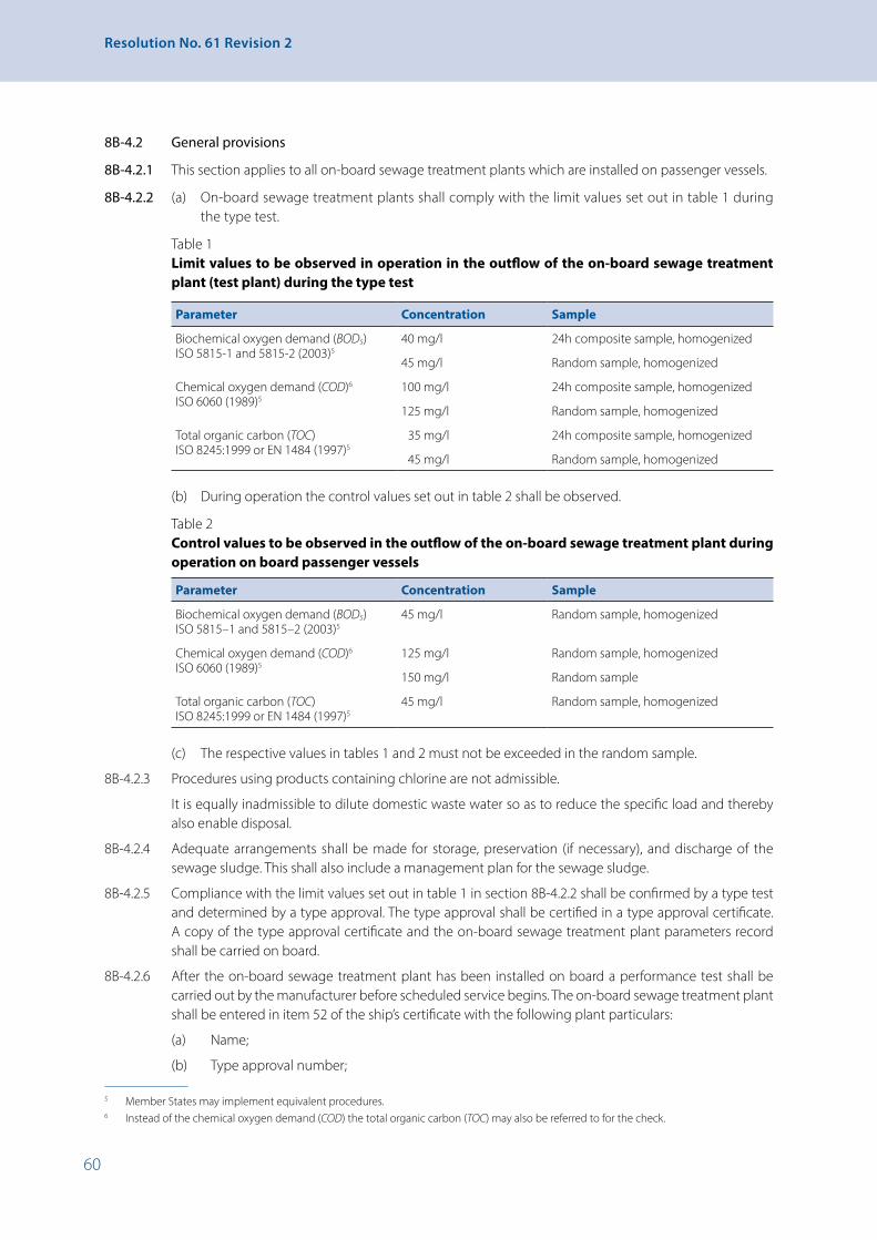
60
Resolution No. 61 Revision 2
8B-4.2 General provisions
8B-4.2.1 This section applies to all on-board sewage treatment plants which are installed on passenger vessels.
8B-4.2.2 (a) On-board sewage treatment plants shall comply with the limit values set out in table 1 during the type test.
Table 1 Limit values to be observed in operation in the outflow of the on-board sewage treatment
plant (test plant) during the type test
Parameter Concentration Sample
Biochemical oxygen demand (BOD5) ISO 5815-1 and 5815-2 (2003)5
40 mg/l 24h composite sample, homogenized
45 mg/l Random sample, homogenized
Chemical oxygen demand (COD)6 ISO 6060 (1989)5
100 mg/l 24h composite sample, homogenized
125 mg/l Random sample, homogenized
Total organic carbon (TOC) ISO 8245:1999 or EN 1484 (1997)5
35 mg/l 24h composite sample, homogenized
45 mg/l Random sample, homogenized
(b) During operation the control values set out in table 2 shall be observed.
Table 2 Control values to be observed in the outflow of the on-board sewage treatment plant during
operation on board passenger vessels
Parameter Concentration Sample
Biochemical oxygen demand (BOD5) ISO 5815–1 and 5815–2 (2003)5
45 mg/l Random sample, homogenized
Chemical oxygen demand (COD)6
ISO 6060 (1989)5125 mg/l Random sample, homogenized
150 mg/l Random sample
Total organic carbon (TOC) ISO 8245:1999 or EN 1484 (1997)5
45 mg/l Random sample, homogenized
(c) The respective values in tables 1 and 2 must not be exceeded in the random sample.56
8B-4.2.3 Procedures using products containing chlorine are not admissible.
It is equally inadmissible to dilute domestic waste water so as to reduce the specific load and thereby also enable disposal.
8B-4.2.4 Adequate arrangements shall be made for storage, preservation (if necessary), and discharge of the sewage sludge. This shall also include a management plan for the sewage sludge.
8B-4.2.5 Compliance with the limit values set out in table 1 in section 8B-4.2.2 shall be confirmed by a type test and determined by a type approval. The type approval shall be certified in a type approval certificate. A copy of the type approval certificate and the on-board sewage treatment plant parameters record shall be carried on board.
8B-4.2.6 After the on-board sewage treatment plant has been installed on board a performance test shall be carried out by the manufacturer before scheduled service begins. The on-board sewage treatment plant shall be entered in item 52 of the ship’s certificate with the following plant particulars:
(a) Name;
(b) Type approval number;
5 Member States may implement equivalent procedures.6 Instead of the chemical oxygen demand (COD) the total organic carbon (TOC) may also be referred to for the check.
61
CHAPTER 8B - Prevention of Water Pollution and Abatement of Noise Produced by Vessels
(c) Serial number;
(d) Year of construction.
8B-4.2.7 Any significant modification to an on-board sewage treatment plant that has an effect on the sewage treatment shall always be followed by a special test in accordance with paragraph 8B-4.11.3.
8B-4.2.8 The competent authority may make use of a technical service in order to fulfil the tasks as described in this section.
8B-4.2.9 The on-board sewage treatment plant shall be regularly maintained in accordance with the manufacturer’s instructions in order to ensure that it is in perfect working order. A maintenance log corroborating such maintenance shall be carried on board.
8B-4.3 Application for type approval
8B-4.3.1 An application for type approval for an on-board sewage treatment plant type shall be submitted by the manufacturer to the competent authority. An information folder in accordance with paragraph 8B-4.1.6 and the draft of an on-board sewage treatment plant parameters record in accordance with paragraph 8B-4.1.9, as well as the draft of a manufacturer’s guide to checking the components and parameters relevant to sewage treatment for that on-board sewage treatment plant type in accordance with paragraph 8B-4.10.1 shall be enclosed with the application. For the type test the manufacturer shall demonstrate a prototype of the on-board sewage treatment plant.
8B-4.3.2 If, in a particular application for type approval for an on-board sewage treatment plant type, the competent authority finds that the application submitted with regard to the presented plant prototype is not representative of the characteristics of this type of on-board sewage treatment plant as described in appendix 8, part II, addendum I another, if necessary additional, prototype, to be designated by the competent authority, shall be supplied for approval in accordance with paragraph 1.
8B-4.3.3 No application for type approval for an on-board sewage treatment plant type may be submitted to more than one competent authority. A separate application shall be submitted for each on-board sewage treatment plant type to be approved.
8B-4.4 Type approval procedure
8B-4.4.1 The competent authority to which the application is submitted shall issue the type approval for the on-board sewage treatment plant type which corresponds to the descriptions in the information folder and satisfies the requirements of this section. The fulfilling of these requirements will be examined in accordance with appendix 9.
8B-4.4.2 For each on-board sewage treatment plant type that it type-approves, the competent authority shall complete all relevant parts of the type approval certificate, the model for which is to be found in appendix 8, part III, and shall compile or verify the contents of the index to the information package. Type approval certificates shall be numbered in accordance with the method described in appendix 8, part IV. The completed type approval certificate and its appendices shall be delivered to the applicant.
8B-4.4.3 If the on-board sewage treatment plant to be approved can only fulfil its function or only has specific properties in conjunction with other components of the vessel in which it is to be installed and if for this reason compliance with one or more requirements can only be checked if the on-board sewage treatment plant to be approved is operated together with other real or simulated components of the vessel, the scope of the type approval for this on-board sewage treatment plant shall be limited accordingly. In such cases, all restrictions on use and all installation requirements shall be detailed in the type approval certificate for that plant type.
8B-4.4.4 Each competent authority shall send the following documents:
(a) the list of on-board sewage treatment plant types including the details as set out in appendix 8, part V, for which it has issued, denied or withdrawn approval in the period in question to the other competent authorities each time this list is amended;

62
Resolution No. 61 Revision 2
(b) if requested to do so by another competent authority:
• a copy of the type approval certificate for the on-board sewage treatment plant type, with or without information package, for each type of on-board sewage treatment plant for which it has issued, denied or withdrawn an approval, and, if applicable,
• the list of the on-board sewage treatment plants which have been manufactured in accordance with the type approvals issued, as laid down in paragraph 8B-4.6.3, which contains the details in accordance with appendix 8, part VI.
8B-4.4.5 Each competent authority shall once a year, or additionally when requested to do so, send to the UNECE secretariat a copy of the data sheet as shown in appendix 8, part VII on the on-board sewage treatment plant types for which an approval has been issued since the last notification.
8B-4.5 Amendment of type approvals
8B-4.5.1 The competent authority which issued the type-approval shall make the necessary arrangements to ensure that it is informed of any change in the particulars appearing in the information package.
8B-4.5.2 The application for amendment or extension of a type approval shall be made exclusively to the competent authority which issued the original type approval.
8B-4.5.3 Should characteristics of the on-board sewage treatment plant as described in the information package have been modified, the competent authority shall:
(a) issue revised pages of the information package as necessary, marking each revised page to show clearly the nature of the change and the date of re-issue. Whenever revised pages are issued, the index to the information package which is attached to the type approval certificate shall also be updated accordingly;
(b) issue a revised type approval certificate (with an extension number) if any information on it (excluding its annexes) has changed or if the minimum requirements of this section have changed since the original approval date. The revised approval certificate shall clearly show the reason for its modification and the date of the re-issue.
Should the competent authority which issued the type approval find that new trials or tests are justified owing to a modification made to the information package, it shall notify the manufacturer of this fact and issue the documents specified above only after new trials or tests have been successfully completed.
8B-4.6 Conformity
8B-4.6.1 The manufacturer shall affix to each on-board sewage treatment plant manufactured in conformity with the type approval the markings as defined in appendix 8, part I, including the type approval number.
8B-4.6.2 Should the type approval contain limitations of usage in accordance with paragraph 8B-4.4.3 the manufacturer shall enclose detailed information on these limitations and all installation requirements with each unit manufactured.
8B-4.6.3 If requested by the competent authority which issued the type approval, the manufacturer shall provide a list of the serial numbers of all on-board sewage treatment plants which have been manufactured in accordance with the requirements set out in this section since the last report, or since the point at which these provisions first came into force, within 45 days after the end of each calendar year, and immediately after each additional date specified by the competent authority. The list shall set out the correlations between the serial numbers, the corresponding on-board sewage treatment plant types and the type approval numbers. Furthermore, the list shall also include particular information for those cases where the manufacturer discontinues production of a typeapproved on-board sewage treatment plant type. Should the competent authority not demand the regular provision of such a list from the manufacturer, the manufacturer shall retain the data recorded for a period of at least 40 years.

63
CHAPTER 8B - Prevention of Water Pollution and Abatement of Noise Produced by Vessels
8B-4.7 Acceptance of equivalent approvals
Member States can recognize type approvals for on-board sewage treatment systems based on different standards for the use on their national waterways. These type approvals should be notified to the UNECE secretariat.
8B-4.8 Checking of serial numbers
8B-4.8.1 The competent authority issuing a type approval shall ensure – if necessary working in conjunction with the other competent authorities – that the serial numbers of the on-board sewage treatment plants manufactured in conformity with the requirements of this section are registered and checked.
8B-4.8.2 An additional check of the serial numbers may take place in conjunction with the check on conformity of production as laid down in paragraph 8B-4.9.
8B-4.8.3 In relation to the checking of the serial numbers, the manufacturer or their authorised representatives located in the member States shall, if requested, promptly supply the competent authority with all necessary information relating to their direct purchasers as well as the serial numbers of those on-board sewage treatment plants which have been reported as manufactured in accordance with paragraph 8B-4.6.3.
8B-4.8.4 Should a manufacturer be unable to comply with the requirements set out in section 8B-4.6 when requested to do so by the competent authority, the approval for the on-board sewage treatment plant type concerned may be withdrawn. In such a case the notification procedure specified in paragraph 8B-4.10.4 shall be used.
8B-4.9 Conformity of production
8B-4.9.1 The competent authority issuing a type approval shall ascertain in advance – if necessary working in conjunction with the other competent authorities – that suitable arrangements have been made to ensure effective checking of conformity of production in respect of the requirements of appendix 8, part I.
8B-4.9.2 The competent authority which has issued a type approval shall ascertain – if necessary working in conjunction with the other competent authorities – that the arrangements specified in paragraph 8B-4.9.1 in respect of the provisions of appendix 8, part I continue to be sufficient and that every on-board sewage treatment plant provided with a type approval number in accordance with the requirements of this section continues to correspond to the description in the type approval certificate and its annexes for the type-approved on-board sewage treatment plant type.
8B-4.9.3. The competent authority may recognise comparable tests by other competent authorities as equivalent to the provisions of paragraphs 8B-4.9.1 and 8B-4.9.2.
8B-4.10 Non-conformity with the type-approved on-board sewage treatment plant type
8B-4.10.1 Non-conformity with the type-approved on-board sewage treatment plant type shall be deemed to exist when there are deviations from the characteristics in the type approval certificate or, as the case may be, from the information package which have not been approved in accordance with paragraph 8B-4.5.3 by the competent authority which issued the type approval.
8B-4.10.2 Should the competent authority which has issued a type approval find that on-board sewage treatment plants do not conform with the on-board sewage treatment plant type for which it issued the approval, it shall take the necessary measures to ensure that on-board sewage treatment plants in production again conform with the type-approved on-board sewage treatment plant type. The competent authority which found the nonconformity shall notify the other competent authorities and the UNECE secretariat of of the measures taken, which may extend to withdrawal of the type approval.
8B-4.10.3 If a competent authority is able to demonstrate that on-board sewage treatment plants provided with a type approval number do not conform with the typeapproved on-board sewage treatment plant type, it may require the competent authority which issued the type approval to have the on-board sewage treatment plant type that is in production checked for conformity with the typeapproved on-board sewage treatment plant type. Such action shall be taken within six months of the date of the request.

64
Resolution No. 61 Revision 2
8B-4.10.4 The competent authorities shall notify each other and the UNECE secretariat within one month of any withdrawal of a type approval and of the reasons for such withdrawal.
8B-4.11 Random sample measurement/Special test
8B-4.11.1 No later than three months after the commissioning of the passenger vessel or, in the case of retrofitting of the on-board sewage treatment plant, after it has been installed and the appropriate performance test has been carried out, the competent authority shall take a random sample during operation of the passenger vessel in order to check the values set out in paragraph 8B-4.2.2, table 2.
At irregular intervals the competent authority shall carry out functionality checks on the on-board sewage treatment plant by means of random sample measurements to check the values set out in paragraph 8B-4.2.2, table 2.
Should the competent authority find that the values of the random sample measurements do not conform with the values set out in paragraph 8B-4.2.2, table 2, it may demand:
(a) that the defects in the on-board sewage treatment plant be remedied so as to ensure that it runs properly;
(b) that the on-board sewage treatment plant be made to conform with the type approval again; or
(c) that a special test be carried out in accordance with paragraph 8B-4.11.3.
Once the non-conformities have been remedied and the on-board sewage treatment plant has been made to conform with the type approval again, the competent authority may carry out new random sample measurements.
If the defects are not remedied or the conformity of the on-board sewage treatment plant with the specifications of the type approval is not restored, the competent authority shall seal the on-board sewage treatment plant and inform the inspection body to make an entry to that effect in item 52 of the ship’s certificate.
8B-4.11.2 The random samples shall be measured in accordance with the specifications of paragraph 8B-4.2.2, table 2.
8B-4.11.3 Should the competent authority find any discrepancies in the on-board sewage treatment plant indicating a deviation from the type approval, the competent authority shall carry out a special test to determine the present state of the on-board sewage treatment plant in relation to the components specified in the on-board sewage treatment plant parameters record, the calibration and the setting of the parameters of the on-board sewage treatment plant.
Should the competent authority come to the conclusion that the on-board sewage treatment plant is not in conformity with the typeapproved on-board sewage treatment plant type, it may take the following actions:
(a) Demand that:
(i) The conformity of the on-board sewage treatment plant be restored, or
(ii) The type approval in accordance with paragraph 8B-4.5 be amended accordingly, or
(b) Order measurement in accordance with the test specification as set out in appendix 9.
If conformity is not restored or the type approval is not amended accordingly, or if it becomes apparent from the measurements made in accordance with point (b) that the limit values laid down in paragraph 8B-4.2.2, table 1 are not complied with, the competent authority shall seal the on-board sewage treatment plant and inform the inspection body to make an entry to that effect in item 52 of the ship’s certificate.

65
CHAPTER 8B - Prevention of Water Pollution and Abatement of Noise Produced by Vessels
8B-4.11.4 The tests in accordance with paragraph 8B-4.11.3 shall be carried out on the basis of the manufacturer’s guide to checking the components and parameters of the on-board sewage treatment plant relevant to sewage treatment. This guide, which shall be compiled by the manufacturer and approved by a competent authority, shall specify the treatmentrelevant components as well as settings, dimensioning criteria and parameters to be applied in order to ensure that the values set out in paragraph 8B-4.2.2, tables 1 and 2 are continuously maintained. It shall include at least the following information:
(a) A specification of the on-board sewage treatment plant type with a process description and an indication of whether wastewater storage tanks are to be installed upstream of the on-board sewage treatment plant;
(b) A list of the components specific to sewage treatment;
(c) The design and dimensioning criteria, dimensioning specifications and regulations applied;
(d) A schematic representation of the on-board sewage treatment plant with identifying features of the approved treatment-relevant components (e.g. part numbers on the components).
8B-4.11.5 An on-board sewage treatment plant that has been shut down may be brought back into service only after a special test in accordance with paragraph 8B-4.11.3, first subparagraph.
8B-4.12 Competent authorities and technical services
8B-4.12.1 Member States shall notify the UNECE secretariat of the names and addresses of the competent authorities and technical services responsible for carrying out the functions outlined in this section. The technical services shall satisfy the standard on general requirements for the competence of testing and calibration laboratories (ISO/IEC 17025: 2005-8), taking the following conditions into account:
(a) Manufacturers of on-board sewage treatment plants cannot be recognised as technical services;
(b) For the purposes of this section a technical service may, with the agreement of the competent authority, make use of facilities external to its own laboratory.
8B-5 Facilities for the collection and storage of vessel operation refuse
A separate container must be provided for vessel operation refuse.
8B-6 Facilities for the collection, storage and treatment of household refuse
8B-6.1 Manned vessels and passenger vessels must be equipped with facilities for the collection of household refuse.
8B-6.2 The volume of household refuse collection facilities Vhr shall be calculated by the formula:
Vhr = Ghr x N x T,
where Ghr – household refuse discharge per person per day according to operating conditions;
N – maximum admissible number of people on board;
T – period between emptyings of the on-board collection facilities.
8B-6.3 Household refuse-collection devices must have easy-to-clean internal surfaces.
8B-6.4 Household refuse-collection equipment must have tightly-closing lids and be installed in wellventilated areas, preferably on the open deck, and must have fittings allowing them to be securely attached to the deck.
8B-6.5 Removable equipment must be designed in such a way that it can be moved by one or two people. Otherwise, appropriate additional equipment must be provided for transport.
8B-6.6 For small vessels, household refuse may be collected in disposable dense polyethylene bags.
8B-7 Requirements concerning facilities for the elimination of household and vessel operation refuse
8B-7.1 The Administration may allow the use of a household and vessel operation refuse incinerator. In this case, such equipment and its components shall meet the conditions required by the Administration.
8B-7.2 In cases where the operation of household and vessel operation refuse incinerators is prohibited on certain waterways, the Administration may put such devices out of action by sealing.
8B-8 Noise emitted by vessels
8B-8.1 Noise emitted by vessels under way, in particular engine intake and exhaust noise, shall be damped by appropriate means.
8B-8.2 Noise emitted by vessels shall not exceed 75 dB(A) at a lateral distance of 25 m from the shipside.
8B-8.3 With the exception of trans-shipment operations, the noise emitted by stationary vessels shall not exceed 65 dB(A) at a lateral distance of 25 m from the shipside.

67
CHAPTER 9 - Electrical Installations
CHAPTER 9 - Electrical Installations
9-1 General
9-1.1 General requirements
9-1.1.1 Where there are no specific requirements concerning certain parts of an installation, the safety level shall be considered satisfactory where those parts have been produced in accordance with an approved European standard or in accordance with the requirements of a recognized Classification Society. The relevant documents shall be submitted to the competent authority on inspection of vessels.
9-1.1.2 The electrical and electronic equipment shall be designed for permanent lists of up to 15° and ambient inside temperatures of between 0 and +40°C, and on the deck between -20°C and +40°C. It shall function perfectly at those limits. The Administration may extend the outside temperature range in accordance with local climatic conditions.
9-1.1.3 The electrical and electronic equipment and appliances shall be fully accessible and easy to maintain.
9-1.2 Electrical supply systems
9-1.2.1 Where vessels are fitted with an electric system that system shall have at least two power sources in such a way that where one power source fails the remaining source is able to supply the equipment needed for navigational safety for an appropriate period of time to be determined by the Administration of the river basin.
9-1.2.2 Adequate sizing of the power supply shall be demonstrated by means of a power balance. An appropriate simultaneity factor may be taken into account.
9-1.3 Documents required to be available on board
Documents containing the following, and duly stamped by the competent authority on inspection of vessels, shall be kept on board:
(i) A set of instructions for use and a description of the electrical installations;
(ii) Wiring diagrams concerning all of the electrical equipment;
(iii) Switching diagrams for the main control panel, the emergency-installation panel and the distribution panels, together with the most important technical data such as the amperage and rated current of the protection and control devices;
(iv) Power data concerning the electrical service equipment;
(v) Types of cable and statement of conductor cross sections;
(vi) All other particulars essential for an assessment of safety.
It is not necessary to keep such documents on board unmanned vessels, but they must be available at all times from the owner.
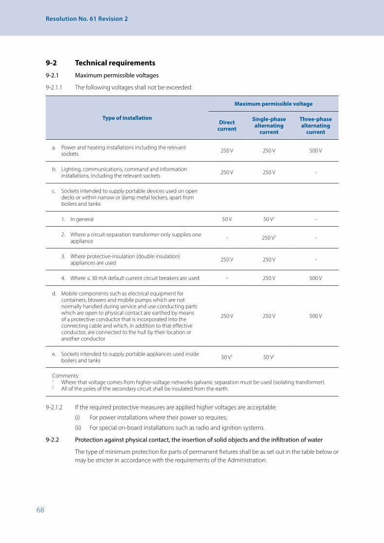
68
Resolution No. 61 Revision 2
9-2 Technical requirements
9-2.1 Maximum permissible voltages
9-2.1.1 The following voltages shall not be exceeded:
Type of installation
Maximum permissible voltage
Direct current
Single-phase alternating
current
Three-phase alternating
current
a. Power and heating installations including the relevant sockets 250 V 250 V 500 V
b. Lighting, communications, command and information installations, including the relevant sockets 250 V 250 V -
c. Sockets intended to supply portable devices used on open decks or within narrow or damp metal lockers, apart from boilers and tanks:
1. In general 50 V 50 V1 -
2. Where a circuit-separation transformer only supplies one appliance - 250 V2 -
3. Where protective-insulation (double insulation) appliances are used 250 V 250 V -
4. Where ≤ 30 mA default current circuit breakers are used - 250 V 500 V
d. Mobile components such as electrical equipment for containers, blowers and mobile pumps which are not normally handled during service and use conducting parts which are open to physical contact are earthed by means of a protective conductor that is incorporated into the connecting cable and which, in addition to that effective conductor, are connected to the hull by their location or another conductor
250 V 250 V 500 V
e. Sockets intended to supply portable appliances used inside boilers and tanks 50 V1 50 V1
Comments:1 Where that voltage comes from higher-voltage networks galvanic separation must be used (isolating transformer).2 All of the poles of the secondary circuit shall be insulated from the earth.
9-2.1.2 If the required protective measures are applied higher voltages are acceptable:
(i) For power installations where their power so requires;
(ii) For special on-board installations such as radio and ignition systems.
9-2.2 Protection against physical contact, the insertion of solid objects and the infiltration of water
The type of minimum protection for parts of permanent fixtures shall be as set out in the table below or may be stricter in accordance with the requirements of the Administration.

69
CHAPTER 9 - Electrical Installations
Location
Type of minimum protection (in accordance with IEC Publication 529)
Generators Motors TransformersPanels
Distributors Switches
Installation equipment
Lighting devices
Service premises, engine rooms, steering-gear compartments
IP 22 IP 222
IP 221, 2
IP 22 IP 44 IP 22
Holds IP 55 IP 55
Battery and paint lockers IP 44 u. (EX)3
Unroofed decks and steering positions IP 55 IP 55 IP 55 IP 55
Enclosed wheelhouse IP 22 IP 22 IP 22 IP 22 IP 22
Accommodation apart from health facilities and washrooms
IP 22 IP 20 IP 20
Health facilities and washrooms IP 44 IP 44 IP 44 IP 55 IP 44
Remarks:1 Where appliances release large amounts of heat: IP 122 Where appliances or panels do not have this type of protection their location shall meet the conditions applying to
that type of protection.3 Electrical equipment of the certified safety type in accordance with IEC Publication 79.
9-2.3 Explosion proofing
Only electrical equipment that has been explosion proofed, (safety-certified) may be installed in premises where potentially explosive gases or mixtures of gases are likely to accumulate, such as compartments set aside for accumulators or the storage of highly inflammable products. No light switches or other electrical appliances shall be installed on those premises. The explosion proofing shall take account of the characteristics of the potentially explosive gases or mixtures of gases that are likely to arise (explosion-potential group, temperature class).
9-2.4 Distribution systems
9-2.4.1 The following distribution systems are allowed for direct and single-phase alternating current:
(i) Two-conductor systems of which one is earthed;
(ii) Single-conductor systems using the hull-return principle, only for local installations (for example, starting gear for combustion engines, cathodic protection);
(iii) Two-conductor systems that are insulated from the hull.
9-2.4.2 The following distribution systems are allowed for three-phase alternating current:
(i) Four-conductor systems with earthing of the neutral point, not using the hull return principle;
(ii) Three-conductor systems insulated from the hull;
(iii) Three-conductor systems with earthing of the neutral point using the hull return principle except for terminal circuits.
9-2.4.3 All such systems shall comply with the rules of the Administration or of a recognized Classification Society.
70
Resolution No. 61 Revision 2
9-2.4.4 The use of other distribution systems shall be subject to the prior consent of the Administration.
9-2.4.5 Connection to the shore or other external networks
9-2.4.5.1 Incoming supply lines from land-based networks or other external networks to the installations of the onboard network shall have a permanent connection on board in the form of fixed terminals or fixed plug sockets. The cable connections shall not be subjected to any pulling load.
9-2.4.5.2 The hull shall be capable of being earthed effectively when the connection voltage exceeds 50 V. The earthing connection shall be specially marked.
9-2.4.5.3 Means shall be provided to prevent the concurrent operation of the onboard network generators and the shore network or another external network. A brief period of concurrent operation shall be permitted when changing from one system to another without a break in voltage.
9-2.4.5.4 The connection shall be protected against short circuits and overloads.
9-2.4.5.5 The main switchboard shall indicate whether the connection is live.
9-2.4.5.6 Indicator devices shall be installed to enable polarity to be compared, in the case of direct current, and phase sequence in the case of alternating current, between the connection and the onboard network.
9-2.4.5.7 A panel on the connection shall indicate:
(i) The measures required to make the connection;
(ii) The types of current and the nominal voltage and, for alternating current, the frequency.
9-2.4.6 Power supply to other vessels
9-2.4.6.1 When power is supplied to other vessels, a separate connection shall be used.
9-2.4.6.2 If power sockets rated at more than 16 A are used to supply current to other vessels, steps shall be taken to ensure (for example, by the use of switches or interlocks) that connection and disconnection can take place only when the line is dead.
9-2.4.6.3 Cables and their connections shall not be subjected to any pulling load.
9-2.4.6.4 Instruction plates shall be affixed to power supply connections and to coupling devices, stipulating that feeders must be disconnected before vessels are uncoupled.
9-2.4.6.5 The supply to the pushed lighters of a convoy shall be controlled by means of switches installed on the pusher.
9-2.4.6.6 Paragraphs 9-2.4.5.3 – 9-2.4.5.7 shall apply by analogy.
9-2.5 Generators and motors
Generators and motors shall be so installed as to be readily accessible for inspection, measurements and repairs and as to prevent water and oil from reaching the windings. Terminal boxes shall be readily accessible, amply dimensioned and sufficiently waterproof. The type of protection should be in accordance with the table in 9-2.2 above.
9-2.6 Accumulators
9-2.6.1 The accumulators shall be of a construction suitable for use on board a vessel. They shall be grouped in boxes or trays fitted with grips to facilitate handling. Cell boxes shall be made of a shock-resistant material that does not easily catch fire and shall be so made as to prevent any spillage of electrolyte at an inclination of 40° from the vertical.
9-2.6.2 Accumulators shall be so arranged as not to shift with the movements of the vessel. They shall not be exposed to excessive heat, extreme cold, spray, steam or vapour. Accumulator batteries shall be installed so as to permit easy access for replacement, topping up and cleaning of the elements, with a space of not less then 15 mm all around them to allow air to circulate, and with no more than 1.5 m separating the deck
71
CHAPTER 9 - Electrical Installations
from the plugs in the uppermost bank. If accumulators are installed on two or more shelves one above the other, at least 50 mm space shall be left at the front and back of each shelf to allow air to circulate.
Accumulator batteries shall not be installed in the wheelhouse, accommodation or holds.
This requirement shall not apply to accumulators for portable appliances, or to accumulators requiring a charging power of less than 0.2 kW.
9-2.6.3 Accumulator batteries requiring a charging power of more than 2 kW (calculated from the maximum charging current and the nominal voltage of the battery) shall be installed in a special battery room. If placed on deck, they shall be enclosed in a cupboard or chest.
Accumulator batteries requiring a charging power not exceeding 2 kW may be installed below decks in a cupboard or chest. They may be installed in the machinery space or any other well-ventilated place provided that they are protected against falling objects and dripping water.
Special battery rooms shall be capable of being heated when the temperature inside them falls below 5°C.
9-2.6.4 The interior surfaces of all battery rooms, including cupboards, lockers, shelving and other built-in fixtures, shall be protected against action of the electrolyte by a coat of paint or a lining made of a material resistant to the electrolyte.
9-2.6.5 Provision shall be made for effective ventilation when batteries are installed in a closed compartment, cupboard or chest. Forced-draught ventilation shall be provided for nickel-cadmium accumulators requiring a charging power of more than 2 kW and for lead-acid accumulators requiring more than 3 kW.
The air shall enter at the bottom and be discharged at the top so that the whole of the battery is swept by the air stream. Ventilation ducts shall not include devices which obstruct the air flow.
The minimum air throughput for ventilation, [m3/h], shall be calculated by the following formula:
Q = 0.11 × I × n
where: l – the maximum charging current (it shall be not less than one quarter of the maximum current admissible by the charging device), [A];
n – the number of cells.
9-2.6.6 Where natural ventilation is used, the cross-section of the ducts shall be sufficient for the required air throughput at an air-flow velocity of 0.5 m/s. It shall be not less than 80 cm2 for lead batteries and not less than 120 cm2 for alkaline batteries.
9-2.6.7 Where the required ventilation cannot be obtained by natural air flow, an exhauster fan shall be provided; its motor shall be clear of the gas stream.
Special devices shall be provided to prevent gases from entering the motor.
Fans shall be of a construction and material precluding the production of sparks through contact between a blade and the fan casing. In addition, the material shall be such as to dissipate any electrostatic charges. Warning symbols “No naked lights or fires and no smoking” corresponding to sketch 2 of appendix 3 with a diameter of at least 10 cm shall be placed on the doors of rooms or cupboards, or the covers of chests, containing batteries.
9-2.7 Electrical switchboards
9-2.7.1 Switchboards shall be situated in accessible and well-ventilated places and be protected against water and mechanical damage.
Switchboards shall not be placed near sounding pipes or near the vent pipes of liquid-fuel tanks.

72
Resolution No. 61 Revision 2
No pressure pipes shall be situated above the main or emergency switchboard or the control panels of propulsion equipment. In vessels where this requirement cannot be met, no pipe joint shall be installed above an electrical switchboard.
9-2.7.2 In general, materials used in the construction of switchboards shall have suitable mechanical strength and be durable, flame-retardant and self-extinguishing. They shall not be hygroscopic.
9-2.7.3 Where the voltage exceeds the safe voltage:
(i) The current-carrying components shall be so arranged or protected as to prevent accidental personal contact;
(ii) An insulating mat or an impregnated wooden grating shall be provided; this shall not apply, however, to subdistribution panels;
(iii) Metal parts of the frames or substructures of control devices and the metal casings of appliances shall be carefully earthed.
9-2.7.4 All parts of switchboards, including the connections, shall be readily accessible for inspection, maintenance or replacement.
9-2.7.5 Marker plates for all circuits shall be affixed to switchboards.
9-2.8 Switches, protective devices
9-2.8.1 Generator circuits and consumer circuits shall be protected against short circuits and overcurrent on all non-earthed conductors. Overload circuit-breakers or-fuses may be used for this purpose. Circuits supplying the steering-gear motors (steering installations) and fire pumps and their control circuits shall only be protected against short circuits. Where circuits include thermal circuit-breakers these shall be neutralized or set at not less than twice the nominal amperage and fitted with an emergency warning light indicating overloading.
9-2.8.2 Outputs from the main switchboard to appliances operating at more than 16 A shall include a load or power switch.
9-2.8.3 Power consumers for the propulsion of the vessel, the steering system, the rudder position indicator, navigation or safety systems, and appliances with a nominal amperage greater than 16 A shall be supplied by separate circuits.
9-2.8.4 The circuits of appliances required for propelling and manoeuvring the vessel shall be supplied directly by the main switchboard.
9-2.8.5 Circuit-breaking equipment shall be selected on the basis of nominal amperage, thermal or dynamic strength, and their breaking capacity. Switches shall simultaneously cut off all live conductors. The switching position shall be identifiable.
9-2.8.6 Fuses shall be of the enclosed-melt type and be made of porcelain or an equivalent material. It shall be possible to change them without any danger of operator contact.
9-2.9 Measuring and monitoring devices
9-2.9.1 Generator, battery and distribution circuits shall be equipped with measuring and monitoring devices where the safe operation of the installation so requires.
9-2.9.2 Non-earthed networks where the voltage is higher than 50 V, must include an earth-insulation checking device equipped with a visual and audible alarm. In secondary installations such as control circuits, this device may be dispensed with.

73
CHAPTER 9 - Electrical Installations
9-2.10 Emergency circuit breakers
Emergency circuit breakers for oil burners, fuel pumps, fuel separators and engine-room ventilators shall be installed outside the premises containing the equipment.
9-2.11 Fixed installations
9-2.11.1 Equipment seals shall be sized as a function of the cables to be connected and be appropriate to the types of cable used.
9-2.11.2 Sockets for distribution circuits at different voltages or frequencies shall be impossible to confuse.
9-2.11.3 Switches shall simultaneously switch off all unearthed conductors within a circuit. However, single-pole switches within unearthed circuitry shall be permitted in accommodation-lighting circuits apart from in laundries, bathrooms and washrooms.
9-2.11.4 Where amperage exceeds 16 A it shall be possible to lock the sockets by means of a switch in such a way that the plug can only be inserted and withdrawn with the power switched off.
9-2.12 Cables
9-2.12.1 Cables shall be flame-retardant, self-extinguishing and resistant to water and oil. In accommodation, other types of cable may be used, provided that they are effectively protected, have flame-retardant characteristics and are self-extinguishing.
9-2.12.2 Cables with conducting wires with a minimum cross-section of 1.5 mm2 shall be used for power circuits and of 1.0 mm2 for lighting circuits.
9-2.12.3 The armouring and metal sheathing of power and lighting circuits shall not, under normal operating conditions, be used as conductor wires or earth wires.
9-2.12.4 The armouring and metal sheathing of power and lighting circuits shall be earthed at least at one end.
9-2.12.5 The cross-section of conductor wires shall take account of the final permissible maximum temperature of conductor wires (maximum permissible amperage) and permissible voltage drop. Such a drop between the main switchboard and the furthermost consumer on the circuit shall not be more than 5 % of nominal voltage for lighting or more then 7 % for power or heating circuits.
9-2.12.6 Cables shall be protected against mechanical damage.
9-2.12.7 The means of fixing the cables shall ensure that any pulling load remains within the permissible limits.
9-2.12.8 When cables pass through partitions or decks, the mechanical strength, watertightness and fire resistance of these partitions and decks shall not be affected by the seals.
9-2.12.9 Cables linking mobile wheelhouses shall be sufficiently flexible and be fitted with insulation with sufficient flexibility down to -20°C and resistance to steam and vapour, ultraviolet rays, ozone, etc.
9-2.13 Lighting
9-2.13.1 In spaces in which accumulators are installed or paint and other highly inflammable substances are stored, limited-explosion-risk lighting appliances shall be used.
9-2.13.2 Lighting appliances shall be so installed that the heat they emit cannot set fire to nearby inflammable objects or components.
9-2.13.3 Lighting appliances on open decks shall be so installed as not to impede the recognition of signal lights.
9-2.13.4 When two or more lighting appliances are installed in the machinery space, as defined in 1-2, they shall be supplied by at least two different circuits.

74
Resolution No. 61 Revision 2
9-2.14 Signal lights
9-2.14.1 The switchboards for the signal lights shall be installed in the wheelhouse. They shall be supplied by a separate feeder from the main switchboard or by two separate secondary networks.
9-2.14.2 Lights shall be individually supplied from the lighting panel and be individually protected and controlled.
9-2.14.3 Tell-tale lamps or other equivalent devices monitoring the signal lights shall be placed on the switchboard in the wheelhouse. No fault in the monitoring installation mentioned in 7-1.6 shall affect the operation of the light which it monitors.
9-2.14.4 Several lights forming a functional unit and installed together at the same point may be jointly supplied, controlled and monitored. The monitoring installation shall be capable of identifying the failure of any of these lights. However, it shall not be possible to use both light sources in a double light (two lights mounted one above the other or in the same housing) simultaneously.
9-2.15 Earthing
9-2.15.1 Electrical equipment operating at a voltage of more than 50 V needs to be earthed.
9-2.15.2 Metal parts of electrical equipment that are not electrically live and can be touched by people, such as machinery frames and casings, appliances and lighting equipment, shall be earthed separately where these are not in electrical contact with the hull as a result of their installation.
9-2.15.3 The housings of mobile electrical consumers and portable appliances shall be earthed by means of an additional conductor that is incorporated into the power cable.
That prescription does not apply where a circuit-separation transformer is used, nor to appliances fitted with protective insulation (double insulation).
9-2.15.4 The cross section of the earthing conductors shall be not less than as set out in the table below:
Cross section of outside conductors [mm2]
Minimum cross section of earthing conductors
in insulated cables [mm2] fitted separately [mm2]
from 0.5 to 4 same cross section as that of the outside conductor 4
more than 4 to 16 same cross section as that of the outside conductor
same cross section as that of the outside conductor
more than 16 to 35 16 16
more than 35 to 120 half of the cross section of the outside conductor
half of the cross section of the outside conductor
more than 120 70 70
9-2.16 Emergency source of electric power
9-2.16.1 (i) Every vessel navigating in zone 1 shall be equipped with an emergency source of electric power.
(ii) Every passenger vessel navigating in zones 2 and 3 shall be equipped with an emergency source of electric power.
The Administration may prescribe more detailed requirements concerning emergency source of electric power, depending on the type and purpose of the vessel.
9-2.16.2 If a vessel navigating in zones 2 and 3, other than a passenger vessel not less than 25 m in length, is equipped with two or more independent sources of power, one of them may be accepted as an emergency source of power.

75
CHAPTER 9 - Electrical Installations
9-2.16.3 The emergency source of power may be:
(i) Either an auxiliary set whose fuel supply system and cooling system are independent of the main machinery, and which is automatically started and connected to the network as soon as the voltage falls on the bus-bars of the main switchboard. The electric power shall be supplied within 30 seconds after the failure of the main electricity supply. The Administration or a recognized Classification Society may permit manual starting if the auxiliary set is installed in the immediate vicinity of a station which is permanently manned and which is outside the machinery space;
(ii) Or an accumulator battery automatically taking up current-supply duty in a network failure and capable of meeting the requirements of paragraph 9-2.16.5 for the prescribed time without having to be recharged and without a voltage drop exceeding that authorized. The Administration or a recognized Classification Society may permit manual switching on from a station which is permanently manned and which is outside the machinery space.
On passenger vessels, power for emergency lighting shall be supplied within seven seconds.
9-2.16.4 The emergency source and its switchboard shall be installed:
(i) On vessels navigating in zone 1, above the freeboard deck and outside the machinery space;
(ii) On passenger vessels not less than 25 m in length, navigating in zones 2 and 3, above the freeboard deck, outside the machinery space, the spaces housing the power sources referred to in 9-1.2.1, and the space where the main switchboard is located. The location shall be separated from these spaces by watertight partitions that are fire-resistant according to 15-11.2. If the vessel is less than 25 m in length, the emergency source may be installed in the machinery space, as high up as possible;
(iii) On all other vessels navigating in zones 2 and 3, as high up as possible.
If the space housing the emergency source is situated below the freeboard deck, that space shall be accessible from the deck.
The emergency source of power shall not be installed forward of the collision bulkhead.
9-2.16.5 The capacity of the emergency source shall be sufficient to supply all consumers necessary to the safety of all persons on board, due account being taken of consumers which may be required to operate simultaneously. At least the following, if their use is prescribed, and if they each have no independent emergency source of power, shall be supplied simultaneously
(i) Navigation and signal lights;
(ii) Emergency lighting;
(iii) Alarm and safety systems;
(iv) Intercommunication systems;
(v) Radio and telephone equipment;
(vi) Emergency floodlight;
(vii) Controls of fixed fire-fighting installations;
(viii) Fire pump and emergency pump (on passenger vessels) where the auxiliary set as mentioned in 9-2.16.3 (i) is used;
(ix) Emergency steering gear;
(x) The rudder position indicator.
The length of time for which the emergency source of power shall be required to supply the prescribed consumers shall be fixed according to the vessel’s purpose, but shall not be less than 30 minutes.
76
Resolution No. 61 Revision 2
9-2.16.6 At least the following places and stations shall be provided with sufficient emergency lighting:
(i) Places where collective life-saving appliances are stored, handled and launched;
(ii) Accommodation exists and passages;
(iii) Machinery space and its exits;
(iv) The emergency switchboard;
(v) The wheelhouse (with provision for disconnection);
(vi) The space housing the emergency source of power;
(vii) Fire-fighting stations;
(viii) Emergency assembly stations for passengers and crew.
The intensity of the emergency lighting shall be prescribed by the Administration.
9-2.17 Alarm and safety systems
The alarm and safety systems for monitoring and protecting mechanical equipment shall meet the following requirements:
9-2.17.1 Alarm systems
The alarm systems shall be so designed that no failure in the alarm system can result in failure of the apparatus or equipment being monitored. Visual alarms shall remain visible until the fault has been remedied; an alarm with acknowledgement shall be distinguishable from an alarm without acknowledgement. Each alarm shall also comprise an audible warning. It shall be possible to switch off acoustic alarms. Switching off one acoustic alarm shall not prevent another signal from being set off by another cause. Exceptions shall be permitted in the case of alarm systems comprising less than 5 measurement points.
9-2.17.2 Safety systems
Safety systems shall be designed to halt or slow down the operation of the affected equipment, or to warn a permanently-manned station to do so before a critical state is reached. Binary transmitters shall be designed according to the load-current principle. If safety systems are not designed to be self-monitoring their operation must be checkable. Safety systems must be independent of other systems.
9-2.18 Electronic equipment
9-2.18.1 General
The test conditions in 9-2.18.2 below shall apply only to electronic devices and their ancillaries on the steering system and the vessel’s power plants.
9-2.18.2 Test conditions
(i) The stresses arising from the test shall not cause electronic devices to be damaged or to malfunction. The tests in accordance with the international standards, such as publication IEC 92-504 concerning these, shall be carried out with the device in operation, apart from the cold-proofing test;

77
CHAPTER 9 - Electrical Installations
(ii) Variations in voltage and frequency
ParameterVariations
continuous short-duration
GeneralFrequency
Voltage±5 %
±10 %±10 % 5 s
±20 % 1.5 s
Battery operation Voltage ±30 % / -25 % -
(iii) Heating test The sample is brought up to a temperature of 55°C within a half-hour period. After that temperature
has been achieved it is maintained for 16 hours. An operating test is then conducted.
(iv) Cold condition test The sample is shut down and cooled to -25°C and held at that temperature for two hours. The
temperature is then raised to 0°C and an operating test is conducted.
(v) Vibration test The vibration test shall be carried out along the three axes at the resonance frequency of the
appliances or parts for the period of 90 minutes in each case. If no clear resonance emerges the vibration test takes place at 30 Hz. The vibration test takes place via sinusoidal oscillation within the following limits:
General:
f = 2.0 ÷ 13.2 Hz; a = ±1 mm (amplitude a = 0.5 of the vibration width)
f = 13.2 ÷ 100 Hz; acceleration ± 0.7 g.
Equipment intended to be fitted to diesel engines or steering system shall be tested as follows:
f = 2.0 ÷ 25 Hz; a = ± 1.6 mm (amplitude a = 0.5 of the vibration width)
f = 25 ÷ 100 Hz; acceleration ± 4 g.
The sensors intended to be installed in diesel-engine exhaust pipes may be exposed to considerably higher stresses. Account shall be taken of this during the tests.
(vi) The electromagnetic compatibility test shall be carried out on the basis of IEC publications 801-2, 801-3, 801-4, 801-5 at test degree number 3.
(vii) Proof that the electronic equipment is adequate for these test conditions shall be provided by their manufacturer. A certificate by a Classification Society is likewise considered to be proof.
9-2.19 Electromagnetic compatibility
The operation of the electric and electromagnetic systems shall not be impaired by electromagnetic interference. General accompanying measures shall concentrate on:
(i) Disconnection of the transmission paths between the source of interference and the user appliances;
(ii) Reducing the causes of disturbance at their source;
(iii) Reducing the sensitivity of the consumer appliances.

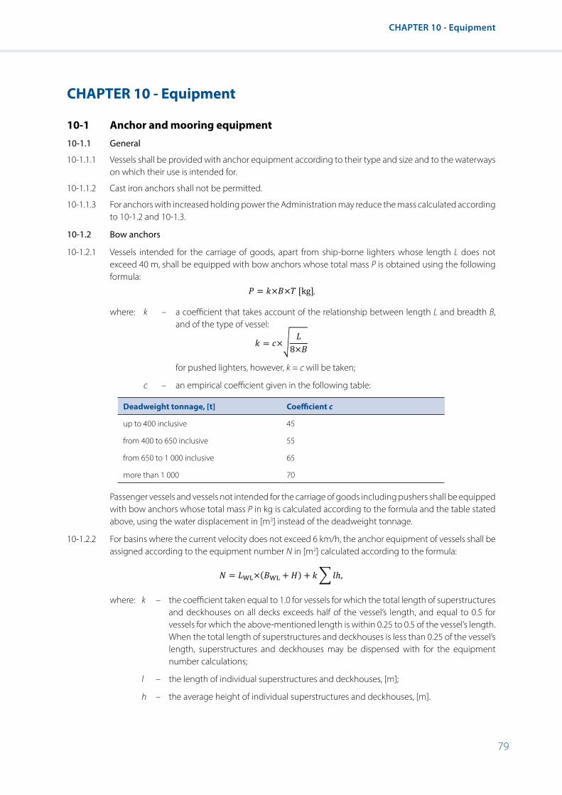
79
CHAPTER 10 - Equipment
CHAPTER 10 - Equipment
10-1 Anchor and mooring equipment
10-1.1 General
10-1.1.1 Vessels shall be provided with anchor equipment according to their type and size and to the waterways on which their use is intended for.
10-1.1.2 Cast iron anchors shall not be permitted.
10-1.1.3 For anchors with increased holding power the Administration may reduce the mass calculated according to 10-1.2 and 10-1.3.
10-1.2 Bow anchors
10-1.2.1 Vessels intended for the carriage of goods, apart from ship-borne lighters whose length L does not exceed 40 m, shall be equipped with bow anchors whose total mass P is obtained using the following formula:
CHAPTER 10
EQUIPMENT
10-1 ANCHOR AND MOORING EQUIPMENT
10-1.1 General
10-1.1.1 Vessels shall be provided with anchor equipment according to their type and size and to the waterways on which their use is intended for.
10-1.1.2 Cast iron anchors shall not be permitted.
10-1.1.3 For anchors with increased holding power the Administration may reduce the mass calculated according to 10-1.2 and 10-1.3.
10-1.2 Bow anchors
10-1.2.1 Vessels intended for the carriage of goods, apart from ship-borne lighters whose length L does not exceed 40 m, shall be equipped with bow anchors whose total mass P is obtained using the following formula:
𝑃𝑃𝑃𝑃 = 𝑘𝑘𝑘𝑘×𝐵𝐵𝐵𝐵×𝑇𝑇𝑇𝑇 [kg],
where k – a coefficient that takes account of the relationship between length L and breadth B, and of the type of vessel:
𝑘𝑘𝑘𝑘 = 𝑐𝑐𝑐𝑐×�𝐿𝐿𝐿𝐿
8×𝐵𝐵𝐵𝐵
for pushed lighters, however, k = c will be taken;
c – an empirical coefficient given in the following table:
Deadweight tonnage, [t] Coefficient c
up to 400 inclusive 45
from 400 to 650 inclusive 55
from 650 to 1 000 inclusive 65
more than 1 000 70
Passenger vessels and vessels not intended for the carriage of goods including pushers shall be equipped with bow anchors whose total mass P in kg is calculated according to the formula and the table stated above, using the water displacement in [m3] instead of the deadweight tonnage.
10-1.2.2 For basins where the current velocity does not exceed 6 km/h, the anchor equipment of vessels shall be assigned according to the equipment number N in [m2] calculated according to the formula:
𝑁𝑁𝑁𝑁 = 𝐿𝐿𝐿𝐿WL×(𝐵𝐵𝐵𝐵WL + 𝐻𝐻𝐻𝐻) + 𝑘𝑘𝑘𝑘�𝑙𝑙𝑙𝑙ℎ,
where: k – the coefficient taken equal to 1.0 for vessels for which the total length of superstructures and deckhouses on all decks exceeds half of the vessel’s length, and equal to 0.5 for vessels for which the above-mentioned length is within 0.25 to 0.5 of the vessel’s length. When the total length of superstructures and
where: k – a coefficient that takes account of the relationship between length L and breadth B, and of the type of vessel:
CHAPTER 10
EQUIPMENT
10-1 ANCHOR AND MOORING EQUIPMENT
10-1.1 General
10-1.1.1 Vessels shall be provided with anchor equipment according to their type and size and to the waterways on which their use is intended for.
10-1.1.2 Cast iron anchors shall not be permitted.
10-1.1.3 For anchors with increased holding power the Administration may reduce the mass calculated according to 10-1.2 and 10-1.3.
10-1.2 Bow anchors
10-1.2.1 Vessels intended for the carriage of goods, apart from ship-borne lighters whose length L does not exceed 40 m, shall be equipped with bow anchors whose total mass P is obtained using the following formula:
𝑃𝑃𝑃𝑃 = 𝑘𝑘𝑘𝑘×𝐵𝐵𝐵𝐵×𝑇𝑇𝑇𝑇 [kg],
where k – a coefficient that takes account of the relationship between length L and breadth B, and of the type of vessel:
𝑘𝑘𝑘𝑘 = 𝑐𝑐𝑐𝑐×�𝐿𝐿𝐿𝐿
8×𝐵𝐵𝐵𝐵
for pushed lighters, however, k = c will be taken;
c – an empirical coefficient given in the following table:
Deadweight tonnage, [t] Coefficient c
up to 400 inclusive 45
from 400 to 650 inclusive 55
from 650 to 1 000 inclusive 65
more than 1 000 70
Passenger vessels and vessels not intended for the carriage of goods including pushers shall be equipped with bow anchors whose total mass P in kg is calculated according to the formula and the table stated above, using the water displacement in [m3] instead of the deadweight tonnage.
10-1.2.2 For basins where the current velocity does not exceed 6 km/h, the anchor equipment of vessels shall be assigned according to the equipment number N in [m2] calculated according to the formula:
𝑁𝑁𝑁𝑁 = 𝐿𝐿𝐿𝐿WL×(𝐵𝐵𝐵𝐵WL + 𝐻𝐻𝐻𝐻) + 𝑘𝑘𝑘𝑘�𝑙𝑙𝑙𝑙ℎ,
where: k – the coefficient taken equal to 1.0 for vessels for which the total length of superstructures and deckhouses on all decks exceeds half of the vessel’s length, and equal to 0.5 for vessels for which the above-mentioned length is within 0.25 to 0.5 of the vessel’s length. When the total length of superstructures and
for pushed lighters, however, k = c will be taken;
c – an empirical coefficient given in the following table:
Deadweight tonnage, [t] Coefficient c
up to 400 inclusive 45
from 400 to 650 inclusive 55
from 650 to 1 000 inclusive 65
more than 1 000 70
Passenger vessels and vessels not intended for the carriage of goods including pushers shall be equipped with bow anchors whose total mass P in kg is calculated according to the formula and the table stated above, using the water displacement in [m3] instead of the deadweight tonnage.
10-1.2.2 For basins where the current velocity does not exceed 6 km/h, the anchor equipment of vessels shall be assigned according to the equipment number N in [m2] calculated according to the formula:
CHAPTER 10
EQUIPMENT
10-1 ANCHOR AND MOORING EQUIPMENT
10-1.1 General
10-1.1.1 Vessels shall be provided with anchor equipment according to their type and size and to the waterways on which their use is intended for.
10-1.1.2 Cast iron anchors shall not be permitted.
10-1.1.3 For anchors with increased holding power the Administration may reduce the mass calculated according to 10-1.2 and 10-1.3.
10-1.2 Bow anchors
10-1.2.1 Vessels intended for the carriage of goods, apart from ship-borne lighters whose length L does not exceed 40 m, shall be equipped with bow anchors whose total mass P is obtained using the following formula:
𝑃𝑃𝑃𝑃 = 𝑘𝑘𝑘𝑘×𝐵𝐵𝐵𝐵×𝑇𝑇𝑇𝑇 [kg],
where k – a coefficient that takes account of the relationship between length L and breadth B, and of the type of vessel:
𝑘𝑘𝑘𝑘 = 𝑐𝑐𝑐𝑐×�𝐿𝐿𝐿𝐿
8×𝐵𝐵𝐵𝐵
for pushed lighters, however, k = c will be taken;
c – an empirical coefficient given in the following table:
Deadweight tonnage, [t] Coefficient c
up to 400 inclusive 45
from 400 to 650 inclusive 55
from 650 to 1 000 inclusive 65
more than 1 000 70
Passenger vessels and vessels not intended for the carriage of goods including pushers shall be equipped with bow anchors whose total mass P in kg is calculated according to the formula and the table stated above, using the water displacement in [m3] instead of the deadweight tonnage.
10-1.2.2 For basins where the current velocity does not exceed 6 km/h, the anchor equipment of vessels shall be assigned according to the equipment number N in [m2] calculated according to the formula:
𝑁𝑁𝑁𝑁 = 𝐿𝐿𝐿𝐿WL×(𝐵𝐵𝐵𝐵WL + 𝐻𝐻𝐻𝐻) + 𝑘𝑘𝑘𝑘�𝑙𝑙𝑙𝑙ℎ,
where: k – the coefficient taken equal to 1.0 for vessels for which the total length of superstructures and deckhouses on all decks exceeds half of the vessel’s length, and equal to 0.5 for vessels for which the above-mentioned length is within 0.25 to 0.5 of the vessel’s length. When the total length of superstructures and
where: k – the coefficient taken equal to 1.0 for vessels for which the total length of superstructures and deckhouses on all decks exceeds half of the vessel’s length, and equal to 0.5 for vessels for which the above-mentioned length is within 0.25 to 0.5 of the vessel’s length. When the total length of superstructures and deckhouses is less than 0.25 of the vessel’s length, superstructures and deckhouses may be dispensed with for the equipment number calculations;
l – the length of individual superstructures and deckhouses, [m];
h – the average height of individual superstructures and deckhouses, [m].

80
Resolution No. 61 Revision 2
For vessels intended to carry cargo on deck, the value of the parameter ∑lh shall be calculated as the product of the lateral projection length of the cargo stowed on the deck together with cargo limiting structures and its average height, and coefficient k shall be taken as 0.5 for vessels intended to carry only loose cargoes in bulk, and 1.0 for vessels intended to carry other deck cargoes.
The mass of bow anchors P in kg shall be not less than:
(i) For vessels having the equipment number N up to 1000 m2:
P = K × N;
(ii) For vessels having the equipment number N = 1000 m2 and over:
P = K × N × (1000 ⁄ N)0.2,
where K – is the coefficient, generally taken equal to 1.0. However, the Basin Administration may assign other value of this coefficient depending on the navigation conditions.
10-1.2.3 Where two bow anchors are provided, their masses shall be equal to each other or differ by not more then 10 %.
10-1.3 Stern anchors
10-1.3.1 Vessels shall be equipped with stern anchors whose total mass is equal to 25 % of mass P calculated in accordance with 10-1.2.1.
Vessels with a maximum length over 86 meters shall be equipped with stern anchors of total mass equal to 50 % of mass P calculated in accordance with 10-1.2.1.
Stern anchors are not required for:
(i) Vessels for which the stern anchor mass will be less than 150 kg;
(ii) Pushed lighters.
10-1.3.2 Vessels intended to push convoys not more than 86 m in length shall be equipped with stern anchors whose total mass is equal to 25 % of mass Р calculated in accordance with 10-1.2.1 for the largest formation (considered to be a nautical unit) permitted and entered in the ship’s certificate.
Vessels intended to push rigid convoys that are longer than 86 m downstream shall be equipped with stern anchors whose total mass is equal to 50 % of mass Р calculated in accordance with 10-1.2.1 for the largest formation (considered to be a nautical unit) permitted and entered in the ship’s certificate.
10-1.3.3 For basins where the current velocity is below 6 km/h, the total mass of stern anchors shall be similarly calculated as in 10-1.3.1 and 10-1.3.2, in accordance with the mass P calculated in 10-1.2.2.
10-1.4 Chains and cables
10-1.4.1 Each bow anchor chain shall have a minimum length of:
• 40 m for vessels not exceeding 30 m in length;
• 10 m greater than the vessel’s length where the vessel’s length is between 30 and 50 m;
• 60 m for vessels more than 50 m in length.
10-1.4.2 Each of the stern anchor chains shall be at least 40 m long. However, where vessels need to stop facing downstream they shall have stern anchor chains that are each at least 60 m in length.
10-1.4.3 Anchor chains shall have a sufficient tensile strength.
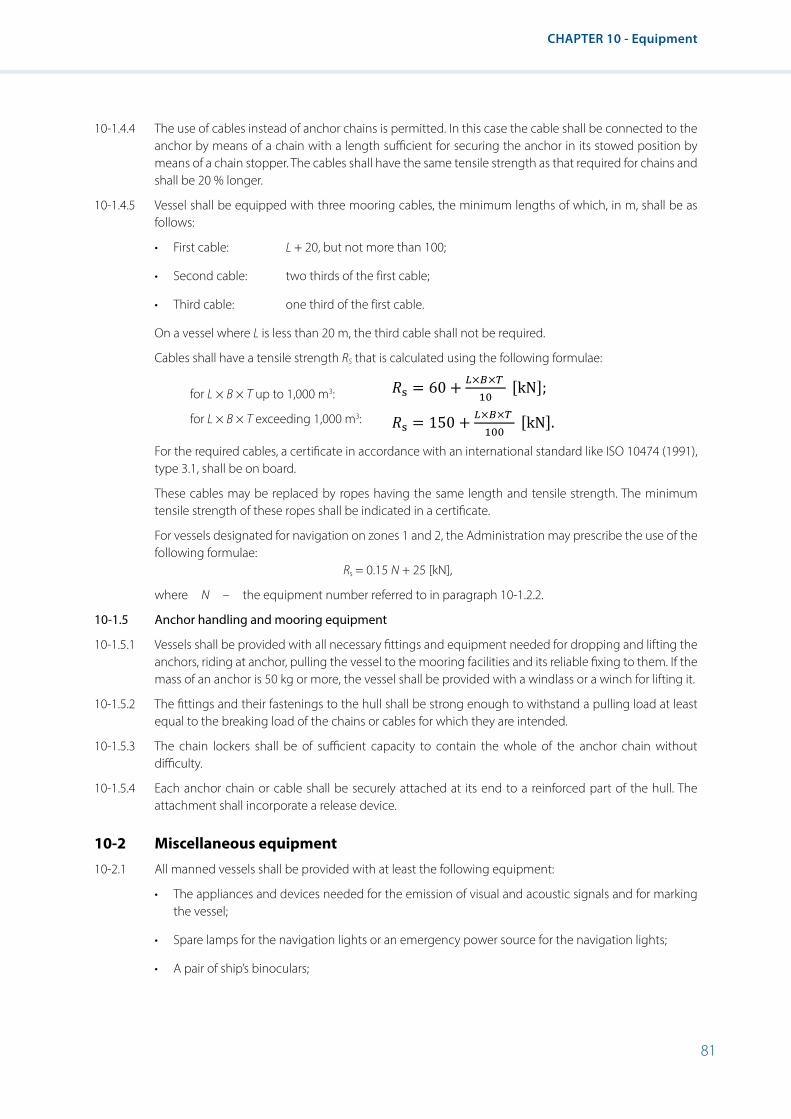
81
CHAPTER 10 - Equipment
10-1.4.4 The use of cables instead of anchor chains is permitted. In this case the cable shall be connected to the anchor by means of a chain with a length sufficient for securing the anchor in its stowed position by means of a chain stopper. The cables shall have the same tensile strength as that required for chains and shall be 20 % longer.
10-1.4.5 Vessel shall be equipped with three mooring cables, the minimum lengths of which, in m, shall be as follows:
• First cable: L + 20, but not more than 100;
• Second cable: two thirds of the first cable;
• Third cable: one third of the first cable.
On a vessel where L is less than 20 m, the third cable shall not be required.
Cables shall have a tensile strength RS that is calculated using the following formulae:
for L × B × T up to 1,000 m3:
for L × B × T exceeding 1,000 m3:
10-1.4 Chains and cables
10-1.4.1 Each bow anchor chain shall have a minimum length of: • 40 m for vessels not exceeding 30 m in length; • 10 m greater than the vessel’s length where the vessel’s length is between 30 and
50 m; • 60 m for vessels more than 50 m in length.
10-1.4.2 Each of the stern anchor chains shall be at least 40 m long. However, where vessels need to stop facing downstream they shall have stern anchor chains that are each at least 60 m in length.
10-1.4.3 Anchor chains shall have a sufficient tensile strength.
10-1.4.4 The use of cables instead of anchor chains is permitted. In this case the cable shall be connected to the anchor by means of a chain with a length sufficient for securing the anchor in its stowed position by means of a chain stopper. The cables shall have the same tensile strength as that required for chains and shall be 20% longer.
10-1.4.5 Vessel shall be equipped with three mooring cables, the minimum lengths of which, in m, shall be as follows:
• First cable: L + 20, but not more than 100;
• Second cable: two thirds of the first cable;
• Third cable: one third of the first cable.
On a vessel where L is less than 20 m, the third cable shall not be required.
Cables shall have a tensile strength Rs that is calculated using the following formulae:
for L × B × T up to 1,000 m3: 𝑅𝑅𝑅𝑅s = 60 + 𝐿𝐿𝐿𝐿×𝐵𝐵𝐵𝐵×𝑇𝑇𝑇𝑇 10
[kN];
for L × B × T exceeding 1,000 m3: 𝑅𝑅𝑅𝑅s = 150 + 𝐿𝐿𝐿𝐿×𝐵𝐵𝐵𝐵×𝑇𝑇𝑇𝑇 100
[kN].
For the required cables, a certificate in accordance with an international standard like ISO 10474 (1991), type 3.1, shall be on board.
These cables may be replaced by ropes having the same length and tensile strength. The minimum tensile strength of these ropes shall be indicated in a certificate.
For vessels designated for navigation on zones 1 and 2, the Administration may prescribe the use of the following formulae:
𝑅𝑅𝑅𝑅s = 0.15 𝑁𝑁𝑁𝑁 + 25 [kN], where N – the equipment number referred to in paragraph 10-1.2.2.
10-1.5 Anchor handling and mooring equipment
10-1.5.1 Vessels shall be provided with all necessary fittings and equipment needed for dropping and lifting the anchors, riding at anchor, pulling the vessel to the mooring facilities and its reliable fixing to them. If the mass of an anchor is 50 kg or more, the vessel shall be provided with a windlass or a winch for lifting it.
For the required cables, a certificate in accordance with an international standard like ISO 10474 (1991), type 3.1, shall be on board.
These cables may be replaced by ropes having the same length and tensile strength. The minimum tensile strength of these ropes shall be indicated in a certificate.
For vessels designated for navigation on zones 1 and 2, the Administration may prescribe the use of the following formulae:
Rs = 0.15 N + 25 [kN],
where N – the equipment number referred to in paragraph 10-1.2.2.
10-1.5 Anchor handling and mooring equipment
10-1.5.1 Vessels shall be provided with all necessary fittings and equipment needed for dropping and lifting the anchors, riding at anchor, pulling the vessel to the mooring facilities and its reliable fixing to them. If the mass of an anchor is 50 kg or more, the vessel shall be provided with a windlass or a winch for lifting it.
10-1.5.2 The fittings and their fastenings to the hull shall be strong enough to withstand a pulling load at least equal to the breaking load of the chains or cables for which they are intended.
10-1.5.3 The chain lockers shall be of sufficient capacity to contain the whole of the anchor chain without difficulty.
10-1.5.4 Each anchor chain or cable shall be securely attached at its end to a reinforced part of the hull. The attachment shall incorporate a release device.
10-2 Miscellaneous equipment
10-2.1 All manned vessels shall be provided with at least the following equipment:
• The appliances and devices needed for the emission of visual and acoustic signals and for marking the vessel;
• Spare lamps for the navigation lights or an emergency power source for the navigation lights;
• A pair of ship’s binoculars;

82
Resolution No. 61 Revision 2
• A loud-hailer;
• A gangway at least 0.4 m wide and 4 m long, fitted with a hand-rail; the competent authority on inspection of vessels may permit shorter gangways for small vessels;
• A sounding device;
• A boathook;
• A suitable equipment for stopping minor leaks;
• A first-aid kit with content in accordance with a relevant standard of the Administration kept in an accommodation room or in the wheelhouse and stored in such a way that it is easily and safely accessible if necessary. If the first-aid kit is stored concealed the cover shall be marked by a symbol for first-aid kit, having a side length of at least 10 cm;
• A notice concerning the rescue of men overboard;
• Two heaving-lines;
• Radio telephone system.
10-2.2 In addition to the requirements of 10-2.1, manned vessels navigating in zone 2 shall be provided with:
• A fixed compass;
• Availability of nautical charts;
• An echo sounder or a sounding lead.
10-2.3 In addition to the requirements of 10-2.1 and 10-2.2 manned vessels navigating in zone 1 shall be provided with:
• Spare lamps for the navigation lights;
• A radio set for receiving weather reports;
• A chronometer at the steering station;
• A pilot-ladder;
• Covers for windows, skylights and other openings which may let in water.
10-3 Fire-fighting appliances
10-3.1 There shall be at least:
(i) In the wheelhouse: 1 portable fire extinguisher;
(ii) Close to each means of access from the deck to the accommodation: 1 portable fire extinguisher;
(iii) Close to each means of access to service premises that are not accessible from the accommodation, and which contain heating, cooking or refrigerating equipment using solid or liquid fuels or liquefied gas: 1 portable fire extinguisher;
(iv) At each entrance to the engine room and boiler rooms: 1 portable fire extinguisher;

83
CHAPTER 10 - Equipment
(v) At suitable points below deck in engine rooms and boiler rooms such that no position in the space is more than 10 metres walking distance away from an extinguisher: 1 portable fire extinguisher.
10-3.2 The extinguishers shall be suitable for their purpose and shall meet the requirements of the Administration or recognized Classification Society. They shall be inspected and checked at least once every two years. A certificate to that effect, signed by the firm or person that carried out the inspection, shall be kept on board.
10-3.3 The extinguishing substance may neither be halon nor contain a product which is likely to release toxic gases, such as carbon tetrachloride during use. Portable fire extinguishers using CO2 may only be used to fight fires at specific locations such as electrical installations, kitchens; the quantity of CO2 shall not constitute a health hazard.
10-3.4 Extinguishers sensitive to frost or heat shall be installed or protected in such a manner that they are always ready for use.
10-3.5 If the fire-fighting appliances are so installed as to be concealed from view, the plates or doors concealing them shall bear a symbol corresponding to relevant sketches of appendix 3 with a side length of at least 10 cm.
10-3.6 Fixed fire-extinguishing installations shall meet the requirements of the Administration or of a recognized Classification Society. The use of halon is not authorized. The equipment shall be checked at least every two years by an approved expert. The dated inspection certificates, signed by the inspector involved, shall be kept on board.
10-3.7 In addition to the above provisions of this chapter, all vessels intended for navigation in zone 1 shall be provided with fire pumps, pressure piping for fire-extinguishing water, and fire hydrants and hoses. The equipment shall meet the requirements of the Administration or recognized Classification Society.
10-3.8 In addition to the above provisions of this chapter, vessels with a length of 110 m or more and intended for navigating in zone 1 shall have a fixed fire-extinguishing installation installed in:
(i) Rooms in which main or auxiliary oil-fired boilers are installed and rooms containing fuel pumps or settling tanks;
(ii) Rooms containing internal combustion engines constituting the main means of propulsion or used as auxiliary machinery with the installed total capacity of not less than 750 kW.
10-4 Hoisting gear, rigging and equipment
10-4.1 Masts fitted with hoisting gear
10-4.1.1 Masts for supporting derricks shall be made of standardized material or materials approved by a recognized Classification Society.
10-4.1.2 The masts shall be suitably fixed to the vessel and shall be built to adequate scantlings, account being taken of the maximum load on the derricks they are intended to support.
10-4.2 Derricks and other hoisting gear
10-4.2.1 Hoisting gear (including masts and derricks) and all fixed or movable fittings used on board for loading or unloading shall comply with the requirements of the Convention concerning Occupational Safety and Health in Dock Work 1979 (Convention No. 152) adopted by the International Labour Office.
10-4.2.2 Hoisting gear other than mentioned in 10-4.2.1 shall meet the requirements of the Administration.

84
Resolution No. 61 Revision 2
10-5 Life-saving appliances
10-5.1 Collective life-saving appliances
10-5.1.1 General requirements
10-5.1.1.1 Collective life-saving appliances shall:
(i) Carry an indication of the use and of the number of persons for which they are approved;
(ii) Have and maintain a stable trim if grabbed by the indicated number of persons;
(iii) Be fitted with a line securely fastened round the outside perimeter enabling them to be grabbed by persons being in water;
(iv) Be made of a suitable material and be resistant to oil and oil products, and to temperatures of up to 50°C;
(v) Have a fluorescent orange colour or have permanently fixed fluorescent surfaces measuring at least 100 cm2;
(vi) Be rapidly and safely launchable from their place of storage by a single person;
(vii) Be checked in accordance with manufacturer’s instructions.
10-5.1.1.2 Inflatable life-saving appliances shall in addition to 10-5.1.1.1:
(i) Comprise at least two separate air compartments;
(ii) Inflate automatically or by manual command when launched;
(iii) Have and maintain a stable trim whatever load it is supporting, even with only half of the air compartments inflated;
(iv) Be checked in accordance with the manufacturer’s instructions.
10-5.1.2 Lifeboats
10-5.1.2.1 All lifeboats shall be well designed and of such shape and proportions that they have ample stability and sufficient freeboard when carrying their full load of persons and equipment.
10-5.1.2.2 All lifeboats shall be strong enough to be lowered into the water with complete safety when carrying their full load of persons and equipment. They shall be of such strength that they will not suffer permanent deformation if subjected to an overload of 25 %.
10-5.1.2.3 Every lifeboat shall meet the following requirements:
(i) It shall be equipped with seats sufficient for at least three persons;
(ii) The number of persons whom the lifeboat is permitted to carry shall be determined according to its cubic capacity as calculated by the recognized methods, on the basis of not less than 0.225 m3 per person. The seating capacity of the lifeboat shall be determined by tests to find out how many adults wearing lifejackets can be accommodated without interfering with the rowing and steering of the lifeboat;
(iii) The lifeboat stability shall be adequate for the maximum number of persons it may carry; its stability shall be deemed to be adequate if, with half the maximum permissible number of persons seated on one side of the lifeboat, there remains a freeboard of not less than 100 mm;
(iv) There shall be a seat width of not less than 0.45 m per person;
(v) The lifeboat shall remain sufficiently buoyant and sufficiently stable when carrying its full load of persons and equipment and filled with water.
10-5.1.2.4 The lifeboat equipment shall meet the requirements of the Basin Administration or a recognized Classification Society.

85
CHAPTER 10 - Equipment
10-5.1.3 Liferafts
10-5.1.3.1 Every liferaft shall be fitted with devices for mooring and towing.
10-5.1.3.2 Every liferaft shall be so constructed as to comprise units containing a volume of air of at least 0.096 m3 (or equivalent buoyancy devices in the case of rigid liferafts), and a deck area of at least 0.372 m2, for every person it is permitted to carry.
10-5.1.3.3 The liferaft shall be so constructed that if it is dropped into the water from a height of 10 metres, neither the liferaft nor its equipment will be damaged.
10-5.1.3.4 Liferaft equipment shall comply with the requirements of the Basin Administration or a recognized Classification Society.
10-5.1.3.5 Inflatable liferafts are in addition to paragraphs 10-5.1.3.1 – 10-5.1.3.4 to meet the following requirements:
(i) Every inflatable liferaft shall be so designed that, when fully inflated and floating, it is stable in the water;
(ii) The liferaft shall be capable of being easily righted by one person in the water if it inflates upside down;
(iii) The liferaft shall be fitted with appropriate means of enabling persons in the water to climb on board;
(iv) The liferaft shall be packed in a valise or container capable of withstanding hard wear and use; the liferaft in its valise or container shall float in such a way as to permit the immediate operation of the inflation system.
10-5.1.3.6 Rigid liferafts shall in addition to paragraphs 10-5.1.3.1 – 10-5.1.3.4 meet the following requirements:
(i) Rigid liferaft shall be so constructed as to retain its shape in all weather conditions, on deck and in the water;
(ii) The deck area of the liferaft shall be situated within that part of the liferaft which affords protection to its occupants. The nature of the deck shall be such as to prevent so far as practicable the ingress of water and it shall effectively hold the occupants out of the water;
(iii) The equipment of the liferaft shall be so stowed as to be readily accessible whichever way up the liferaft is floating.
10-5.1.4 Ship’s boats
10-5.1.4.1 Ship’s boats may be used as a collective life-saving appliance if complying with the requirements of 10-5.1.1.
10-5.1.4.2 The ship’s boats shall meet the following requirements:
(i) They shall be easy to steer and manoeuvre, they shall maintain their course and not drift significantly under the effect of the wind, the current or the waves;
(ii) They shall have seats for at least three persons;
(iii) They shall be sufficiently resistant;
(iv) Their volume shall be at least 1.5 m3, or the product of Lc × Bc × Hc shall represent at least 2.7 m3;
(v) Their freeboard shall be at least 25 cm with three persons of approximately 75 kg each on board;
(vi) They shall be adequately stable. This shall be considered adequate if there is a residual freeboard of at least 10 cm when two persons of roughly 75 kg each are on one side as close as possible to the gunwale;
(vii) Their buoyancy in N with no passengers on board, but completely filled with water, shall be at least equal to 300 × LC × BC × HC;

86
Resolution No. 61 Revision 2
(viii) The following gear shall be on board:
• One set of oars;
• One mooring rope;
• One bailer.
10-5.1.4.3 It shall be possible for one person to launch such ship’s boats safely. If a power-driven unit is used for launching it should be ensured that a failure of the power supply will not jeopardize rapid and safe launching.
10-5.1.4.4 Inflatable ship’s boats shall be permitted provided the conditions set out in paragraphs 10-5.1.4.2 and 10-5.1.4.3 are met, that they are permanently operational and that they have several compartments.
10-5.1.4.5 If a ship’s boat is used on a passenger vessel as a lifeboat it shall at least meet the conditions set out in paragraph 10-5.1.4.2. However,
(i) Seat width shall be at least 0.45 m per person, while the maximum permissible number of persons shall not exceed the product of 3 × LC × BC × HC;
(ii) Their stability shall be considered adequate if there is a freeboard of at least 10 cm when half of the maximum number of passengers permitted are positioned on one side of the ship’s boat.
Note: In paragraphs 10-5.1.4.2 and 10-5.1.4.5:
LС – ship’s boat length, [m];
ВС – ship’s boat width, [m];
HC – the ship’s boat depth, [m].
10-5.1.5 Life-saving buoyancy aids
Life-saving buoyancy aids shall provide a buoyancy of at least 100 N (Newton) per person in fresh water.
10-5.2 Individual life-saving appliances
10-5.2.1 General requirements
Individual life-saving appliances shall meet the following requirements:
(i) To provide a buoyancy of at least 100 N in fresh water;
(ii) To be made of a suitable material and be resistant to oil and oil products, and to temperatures of up to 50°C;
(iii) Have a fluorescent orange colour or have permanently fixed fluorescent surfaces measuring at least 100 cm2;
(iv) To be capable of supporting an iron load of 7.5 kg in fresh water for 24 hours.
10-5.2.2 Lifejackets
10-5.2.2.1 A lifejacket shall satisfy the following requirements:
(i) It shall be capable of keeping the head of an exhausted or unconscious person above water;
(ii) It shall be so designed as to eliminate so far as possible all risk of its being put on incorrectly; however, it shall be capable of being worn inside out;
(iii) It shall be capable of turning the wearer’s body, on entering the water, to a safe floating position slightly inclined backwards from the vertical;
(iv) It shall be easy and quick to put on, and shall fasten securely to the body.
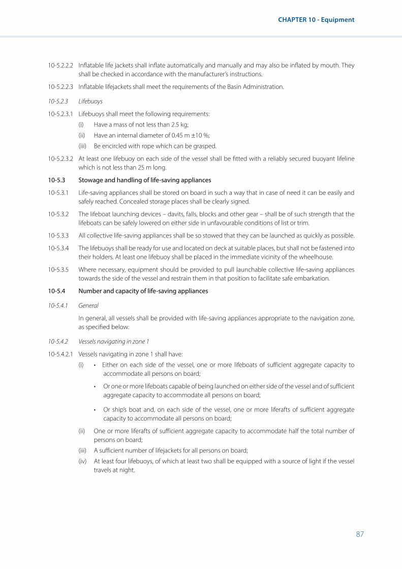
87
CHAPTER 10 - Equipment
10-5.2.2.2 Inflatable life jackets shall inflate automatically and manually and may also be inflated by mouth. They shall be checked in accordance with the manufacturer’s instructions.
10-5.2.2.3 Inflatable lifejackets shall meet the requirements of the Basin Administration.
10-5.2.3 Lifebuoys
10-5.2.3.1 Lifebuoys shall meet the following requirements:
(i) Have a mass of not less than 2.5 kg;
(ii) Have an internal diameter of 0.45 m ±10 %;
(iii) Be encircled with rope which can be grasped.
10-5.2.3.2 At least one lifebuoy on each side of the vessel shall be fitted with a reliably secured buoyant lifeline which is not less than 25 m long.
10-5.3 Stowage and handling of life-saving appliances
10-5.3.1 Life-saving appliances shall be stored on board in such a way that in case of need it can be easily and safely reached. Concealed storage places shall be clearly signed.
10-5.3.2 The lifeboat launching devices – davits, falls, blocks and other gear – shall be of such strength that the lifeboats can be safely lowered on either side in unfavourable conditions of list or trim.
10-5.3.3 All collective life-saving appliances shall be so stowed that they can be launched as quickly as possible.
10-5.3.4 The lifebuoys shall be ready for use and located on deck at suitable places, but shall not be fastened into their holders. At least one lifebuoy shall be placed in the immediate vicinity of the wheelhouse.
10-5.3.5 Where necessary, equipment should be provided to pull launchable collective life-saving appliances towards the side of the vessel and restrain them in that position to facilitate safe embarkation.
10-5.4 Number and capacity of life-saving appliances
10-5.4.1 General
In general, all vessels shall be provided with life-saving appliances appropriate to the navigation zone, as specified below.
10-5.4.2 Vessels navigating in zone 1
10-5.4.2.1 Vessels navigating in zone 1 shall have:
(i) • Either on each side of the vessel, one or more lifeboats of sufficient aggregate capacity to accommodate all persons on board;
• Or one or more lifeboats capable of being launched on either side of the vessel and of sufficient aggregate capacity to accommodate all persons on board;
• Or ship’s boat and, on each side of the vessel, one or more liferafts of sufficient aggregate capacity to accommodate all persons on board;
(ii) One or more liferafts of sufficient aggregate capacity to accommodate half the total number of persons on board;
(iii) A sufficient number of lifejackets for all persons on board;
(iv) At least four lifebuoys, of which at least two shall be equipped with a source of light if the vessel travels at night.

88
Resolution No. 61 Revision 2
10-5.4.2.2 Vessels navigating in zone 1 need not be equipped with liferafts provided that they are equipped with lifeboats in accordance with paragraph 10-5.4.2.1, subparagraph (i), first item above.
10-5.4.3 Vessels navigating in zones 2 and 3
Vessels navigating in zones 2 and 3 shall have:
(i) Collective life-saving appliances conforming in number and capacity to the requirements of the Basin Administration or a recognized Classification Society;
(ii) A sufficient number of lifejackets for all persons on board;
(iii) At least three lifebuoys for smaller vessels, although two lifebuoys may be allowed by the Basin Administration. At least one of these buoys shall be equipped with a source of light if the vessel travels at night.
These provisions shall not apply to unmanned vessels such as pushed lighters.
10-5.5 Carriage of ship’s boats
The following vessels shall carry a ship’s boat:
(i) Self-propelled vessels and manned towed barges of more than 150 tonne dwt;
(ii) Tugs and pushers of more than 150 m3 water displacement;
(iii) Floating equipment;
(iv) Passenger vessels.

89
CHAPTER 11 - Working Spaces
CHAPTER 11 - Working Spaces
11-1 General
11-1.1 Vessels shall be built, arranged and equipped in such a way as to enable the crew to work and move about safely.
11-1.2 The necessary on-board working facilities including permanent fixtures shall be arranged, laid out and protected in such a way as to permit safe, easy movement on board, and maintenance. If necessary, moving parts of machinery and hot parts of installations shall be provided with the means to protect people.
11-2 Protection against falling
11-2.1 Decks including side decks and wherever people walk and work shall be free from obstacles likely to cause tripping and it shall be impossible for puddles to remain.
11-2.2 Decks including side decks, engine-room floors, landings, companionway steps and the tops of bollards shall be designed to prevent slipping.
11-2.3 The tops of side deck bollards and obstacles in passageways, such as the edges of steps, shall be painted in a colour contrasting with the surrounding decks.
11-2.4 The outer edges of decks, as well as working spaces where people might fall more than 1 metre, shall be fitted with bulwarks or coamings or with a guard rail, which shall comprise a handrail at least 0.90 m high, a rail at knee height and a foot-rail. Coamings may be fitted with a hand-rail only. Coaming hand-rails shall not be required where side decks are fitted with non-retractable guard rails.
11-3 Dimensions of working spaces
Working spaces shall be large enough to provide every person working in them with adequate freedom of movement.
11-4 Side deck
11-4.1 The clear width of the side deck shall be at least 0.60 m. That figure may be reduced to 0.5 m at certain positions where necessary installations are located such as deck-swabbing cocks and to 0.4 m at bollard emplacements.
11-4.2 Up to a height of 0.90 m above the side deck, the clear width of the side deck may be reduced to 0.50 m provided that the clear width above, between the outer edge of the hull and the inner edge of the hold, is not less than 0.65 m.
11-4.3 The requirements of 11-4.1 and 11-4.2 shall apply up to a height of 2.00 m above the side deck.
11-5 Access to working spaces
11-5.1 Points of access and passageways for the movement of people and objects shall be of sufficient size and so arranged that:
(i) In front of the access opening, there is sufficient room not to impede movement;
(ii) The clear width of the passageway shall be appropriate for the intended use of the working space and shall be not less than 0.60 m, except in the case of vessels less than 8 m wide, where it may be reduced to 0.50 m;
(iii) The height of the access opening including the coaming, if any, is not less than 1.90 m.
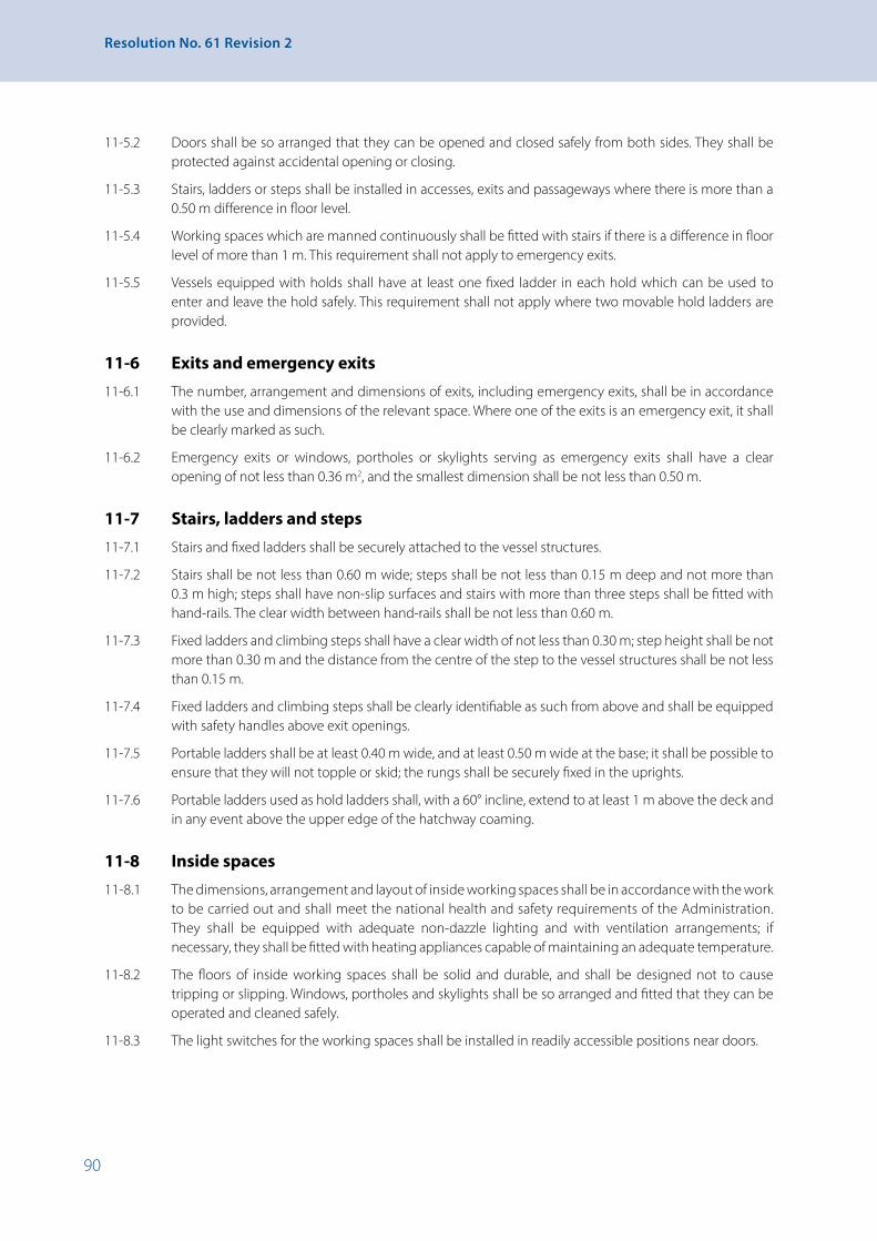
90
Resolution No. 61 Revision 2
11-5.2 Doors shall be so arranged that they can be opened and closed safely from both sides. They shall be protected against accidental opening or closing.
11-5.3 Stairs, ladders or steps shall be installed in accesses, exits and passageways where there is more than a 0.50 m difference in floor level.
11-5.4 Working spaces which are manned continuously shall be fitted with stairs if there is a difference in floor level of more than 1 m. This requirement shall not apply to emergency exits.
11-5.5 Vessels equipped with holds shall have at least one fixed ladder in each hold which can be used to enter and leave the hold safely. This requirement shall not apply where two movable hold ladders are provided.
11-6 Exits and emergency exits
11-6.1 The number, arrangement and dimensions of exits, including emergency exits, shall be in accordance with the use and dimensions of the relevant space. Where one of the exits is an emergency exit, it shall be clearly marked as such.
11-6.2 Emergency exits or windows, portholes or skylights serving as emergency exits shall have a clear opening of not less than 0.36 m2, and the smallest dimension shall be not less than 0.50 m.
11-7 Stairs, ladders and steps
11-7.1 Stairs and fixed ladders shall be securely attached to the vessel structures.
11-7.2 Stairs shall be not less than 0.60 m wide; steps shall be not less than 0.15 m deep and not more than 0.3 m high; steps shall have non-slip surfaces and stairs with more than three steps shall be fitted with hand-rails. The clear width between hand-rails shall be not less than 0.60 m.
11-7.3 Fixed ladders and climbing steps shall have a clear width of not less than 0.30 m; step height shall be not more than 0.30 m and the distance from the centre of the step to the vessel structures shall be not less than 0.15 m.
11-7.4 Fixed ladders and climbing steps shall be clearly identifiable as such from above and shall be equipped with safety handles above exit openings.
11-7.5 Portable ladders shall be at least 0.40 m wide, and at least 0.50 m wide at the base; it shall be possible to ensure that they will not topple or skid; the rungs shall be securely fixed in the uprights.
11-7.6 Portable ladders used as hold ladders shall, with a 60° incline, extend to at least 1 m above the deck and in any event above the upper edge of the hatchway coaming.
11-8 Inside spaces
11-8.1 The dimensions, arrangement and layout of inside working spaces shall be in accordance with the work to be carried out and shall meet the national health and safety requirements of the Administration. They shall be equipped with adequate non-dazzle lighting and with ventilation arrangements; if necessary, they shall be fitted with heating appliances capable of maintaining an adequate temperature.
11-8.2 The floors of inside working spaces shall be solid and durable, and shall be designed not to cause tripping or slipping. Windows, portholes and skylights shall be so arranged and fitted that they can be operated and cleaned safely.
11-8.3 The light switches for the working spaces shall be installed in readily accessible positions near doors.

91
CHAPTER 11 - Working Spaces
11-9 Protection against noise and vibration
11-9.1 Working spaces shall be so situated, equipped and designed that crew members are not exposed to harmful vibrations.
11-9.2 Permanent working spaces shall be so constructed and soundproofed that the health and safety of crew members are not adversely affected by excessive noise.
11-9.3 Spaces and areas in which people are continuously exposed to noise levels that exceed 85 dB(A) should be marked with signs “Use ear protectors” in accordance with sketch 7 of appendix 3 with diameter of at least 10 cm and people who work in them should use individual acoustic protection devices.
11-9.4 The maximum permissible sound pressure level in the engine rooms shall be 110 dB(A). The measuring points shall be selected as a function of the maintenance work needed during normal operation of the plant located therein.
11-10 Hatch covers
11-10.1 Hatch covers shall be easily accessible and safe to handle. Hatch-cover components weighing more than 40 kg shall be designed to slide or pivot or be fitted with mechanical opening devices. Hatch covers operated by lifting gear shall be fitted with easily accessible attachment devices. Non-interchangeable hatch covers and hatch beams shall be clearly marked to show the hatches to which they belong and their correct positions on those hatches.
11-10.2 Hatch covers shall have provision for being firmly secured in their working position. Sliding covers shall be capable of being locked in their final positions; they shall be fitted with catches to prevent accidental horizontal movement of more than 0.40 m in any other position. Appropriate devices shall be fitted to hold stacked hatch covers in position.
11-10.3 The power supply for mechanically operated hatch covers must be cut off automatically when the control switch is released.
11-10.4 Hatch covers must be capable of bearing the loads to which they are likely to be subjected: if less than 12 people, each assumed to weigh 75 kg, can be supported on a load-supporting hatch cover, a notice stating the number of persons that such a hatch cover can support shall be prominently displayed. Hatch covers designed to receive deck cargo shall have the permissible load in t/m2 marked on them. Where braces are needed to support the maximum permissible load this shall be indicated in an appropriate place, in which case the relevant drawings shall be kept on board.
11-11 Winches
11-11.1 Winches shall be designed in such a way as to enable work to be carried out safely. They shall be fitted with devices that prevent unintentional load release. Winches that do not lock automatically shall be fitted with a brake that is adequate to deal with their tractive force.
11-11.2 Hand-operated winches shall be fitted with devices to prevent kick-back of the crank. Winches that are both power driven and hand-operated shall be designed in such a way that the motive-power control cannot actuate the hand-operated control.

93
CHAPTER 12 - Crew Accommodation
CHAPTER 12 - Crew Accommodation
12-1 General
12-1.1 Vessels shall have accommodation for the persons lodging habitually on board, and at least for the minimum crew.
12-1.2 Accommodation shall be so designed, arranged and fitted out as to meet the health, safety and comfort needs of those on board. It shall be of safe and easy access and insulated against heat and cold. Where there is no deck-level access to the accommodation and the difference in level is 0.30 m or more, the accommodation shall be accessible by means of companionways. In the fore section of the vessel no floor shall be more than 1.20 m below the plane of maximum draught.
12-1.3 The competent authority may authorize derogations to the prescriptions of this chapter if the health and safety of those on board are ensured by other means. The competent authority shall indicate on the ship’s certificate any restrictions to the vessel’s operating mode/entry into service resulting from the derogations.
12-2 Special design requirements
12-2.1 Location and condition
12-2.1.1 No accommodation shall be located ahead of the plane of the collision bulkhead.
12-2.1.2 The accommodation shall be separated from engine- and boiler rooms by gastight bulkheads and from the holds by watertight bulkheads that extend up to the deck.
12-2.1.3 The accommodation shall be directly accessible from the deck.
12-2.1.4 The accommodation complex shall have at least one day-room partitioned off from the sleeping quarters.
12-2.1.5 The accommodation shall be so designed and arranged as to prevent as far as possible the penetration of foul air from other areas of the vessel such as engine rooms or holds; where forced-air ventilation is used the intake vents shall be so placed as to satisfy the above requirements. The exhaust air from galleys or spaces equipped with sanitary installations shall be expelled directly from the vessel.
12-2 1.6 It shall be possible to heat accommodation in accordance with its intended use. Heating installations shall be appropriate for the weather conditions which may arise.
12-2.1.7 It shall be possible to ventilate the accommodation adequately.
12-2.1.8 Accommodation shall be protected against noise and vibration. Sound pressure levels shall not exceed:
(i) 70 dB(A) in the living quarters;
(ii) 60 dB(A) in the sleeping quarters. This provision does not apply to vessels operating exclusively no more then 14 hours per day. The operating mode restriction shall be mentioned on the certificate.
12-2.1.9 The accommodation shall be provided with emergency exits permitting rapid evacuation. Exits of living and sleeping quarters shall comply with the requirements of paragraph 12-1.2.
12-2.1.10 Pipes carrying dangerous gases or liquids, or which are subjected to such high internal pressure in which the slightest leak could pose a danger to human beings, shall not be located in the accommodation or in corridors leading to the accommodation. An exception to this rule is made for hydraulic system pipes, provided they are fitted in metal casings, and for the pipes of liquefied gas installations for domestic purposes.
94
Resolution No. 61 Revision 2
12-2.2 Dimensions of the accommodation
12-2.2.1 The clear headroom in the accommodation shall be not less than 2.00 m.
12-2.2.2 The free floor area of the living quarters shall be not less than 2 m2 per person, and in any event not less than 8 m2 in total (not counting furniture, except tables and chairs).
12-2.2.3 The volume of air per person shall be at least 3.5 m3 in living quarters. In the sleeping quarters, it shall be at least 5 m3 for the first occupant and at least 3 m3 for each additional occupant (not counting the volume of furniture). Sleeping cabins shall, as far as possible, be intended for no more than two persons.
12-2.2.4 The cubic capacity of each unit in the living and sleeping quarters shall be not less than 7 m3.
12-3 Approaches, doors and stairways
12-3.1 Doors shall have a total height, coamings included, of at least 1.90 m and a clear width of at least 0.60 m. The prescribed height may be achieved by means of sliding or hinged covers or flaps. It shall be possible to open doors from either side. Coamings shall be not more than 0.40 m high, but shall nonetheless comply with the provisions of other safety regulations.
12-3.2 Companionways shall be permanently fixed and safely negotiable. They shall be deemed to be so when they are constructed according to the requirements of section 11-7.
12-4 Daylight and lighting
12-4.1 The accommodation shall be adequately lighted. The living quarters, galleys and, if possible, the other compartments shall be accessible to daylight.
12-4.2 Standards of natural and artificial illumination shall be fixed by the Administration.
12-5 Fittings
12-5.1 Each crew member living on board shall be provided with an individual berth and an individual clothes locker fitted with a lock. The internal measurements of the berth shall be not less than 2.00 x 0.90 m. The height of the locker shall be not less than 1.70 m and the available horizontal area not be less then 0.25 m2.
12-5.2 Berths shall be not less than 0.30 m above the floor. Where one berth is placed over another, the clear headroom above each berth shall be not less than 0.60 m. Berths shall not be arranged in tiers of more then two.
12-5.3 Suitable places for storing and drying work clothes shall be provided, but not in the sleeping quarters.
12-6 Galleys and day-rooms (messrooms)
12-6.1 Galleys shall comprise:
(i) A cooker;
(ii) A sink with waste connection;
(iii) A supply of potable water;
(iv) Refrigerator;
(v) Sufficient storage and working space.
12-6.2 Galleys may be combined with day-rooms.
12-6.3 Manned vessels shall have a refrigerator and where necessary cold storerooms. The doors of cold storerooms that are large enough to admit a person must be fitted with locks that can be opened from both sides.

95
CHAPTER 12 - Crew Accommodation
12-6-4 The eating area of combined galleys/day-rooms shall be large enough to accommodate the number of crew normally using it at the same time. Seats shall be not less than 0.60 m wide.
12-7 Sanitary installations
12-7.1 The following sanitary installations at least shall be provided in vessels with accommodation:
(i) One toilet per accommodation unit or per six crew members, which it shall be possible to ventilate with fresh air;
(ii) One wash basin with waste pipe and hot and cold taps connected to a source of potable water per accommodation unit or per four crew members;
(iii) One shower or bath connected up to hot and cold potable water per accommodation unit or per six crew members.
12-7.2 The sanitary installations shall be in close proximity to the accommodation. Toilets shall not have direct access to galleys, mess rooms or combined day-rooms/galleys.
12-7.3 Toilet compartments shall have a floor space of at least 1 m², not less than 0.75 m wide and not less than 1.10 m long. Toilet compartments in cabins for no more than two persons may be smaller. Where a toilet contains a wash basin and/or shower, the surface area shall be increased at least by the surface area occupied by the wash basin and/or shower (or bath).
12-8 Potable-water installations
12-8.1 Vessels with accommodation shall have one or more potable water tanks. Potable water tank filling apertures and potable water pipes shall be marked as being intended exclusively for potable water. Potable water filler necks shall be installed above the deck.
12-8.2 Potable water tanks shall:
(i) Be protected against excessive heating;
(ii) Have a capacity as prescribed by the Basin Administration;
(iii) Be made of a material which resists corrosion and poses no physiological danger;
(iv) Have a suitable, lockable opening to enable the inside to be cleaned;
(v) Have a water level indicator;
(vi) Have ventilation caps to the open air or which are fitted with appropriate filters.
12-8.3 Potable water tanks shall not share walls with other tanks. Potable water pipes shall not pass through tanks containing other liquids. Connections are not permitted between the potable water supply system and other pipes. Pipes carrying gas or liquids other than potable water shall not pass through potable water tanks.
12-8.4 Potable water pressure vessels shall operate only on uncontaminated compressed air. Where it is produced by means of compressors, appropriate air filters and oil separators shall be installed directly in front of the pressure vessel unless the water and the air are separated by a diaphragm.

96
Resolution No. 61 Revision 2
CHAPTER 13 - Fuel-Fired Heating, Cooking and Refrigerating Equipment
(Left void)
97
CHAPTER 14 - Liquefied Gas Installations for Domestic Purposes
CHAPTER 14 - Liquefied Gas Installations for Domestic Purposes
14-1 General
14-1.1 Every gas installation shall consist essentially of one or more gas receptacles, one or more pressure reducers, a distribution system and a number of gas-consuming appliances.
14-1.2 Such installations may be operated only with the gas mixture of which the customary name is propane.
14-2 Installation
14-2.1 Gas installations shall, in all their parts, be suitable for the use of propane and shall be built and installed in accordance with the state of the art.
14-2.2 A gas installation may be used only for domestic purposes in spaces that comply with the requirements of the Administration.
14-2.3 There may be several separate gas installations on board. Accommodation areas separated by a cargo hold or a fixed tank shall not be supplied by the same installation.
14-2.4 Installations which are not permanently fixed may be used only if they meet the special requirements laid down by the Administration.
14-3 Receptacles
14-3.1 Only receptacles with a capacity of between 5 and 35 kg shall be allowed. In the case of passenger vessels, the Basin Administration may approve the use of receptacles with a larger content.
14-3.2 The receptacles shall satisfy the requirements in force. They shall bear the official stamp certifying that they have passed the statutory tests.
14-4 Location and arrangement of the supply unit
14-4.1 The supply unit shall be installed on deck in a special cupboard located outside the accommodation area in such a position that it does not interfere with movement on board. It shall not, however, be installed against the forward or after bulwark plating. The cupboard may be a wall cupboard set into the superstructure provided that it is gastight to that superstructure and can only be opened to the outside. It shall be so located that the pipes leading to the gas consumption points are as short as possible.
Each installation may have up to four receptacles in operation simultaneously, with or without the use of an automatic changeover valve. The number of receptacles on board, including spare receptacles, shall not exceed six per installation.
On passenger vessels having galleys or canteens for the passengers, up to six receptacles per installation may be in operation simultaneously, with or without the use of an automatic changeover valve. The number of receptacles on board such vessels, including spare receptacles, shall not exceed nine per installation.
The pressure reducer or, in the case of two-stage reduction, the first pressure reducer shall be fitted to the inside wall of the cupboard for the receptacles.
14-4.2 The supply unit shall be so installed that any leaking gas can escape from the cupboard without any risk that it may penetrate the vessel or come into contact with any possible source of ignition.
14-4.3 The cupboard shall be constructed of fire-resistant materials and shall be adequately ventilated by openings at the top and bottom. The cupboard shall be fitted with a locking device preventing unauthorized persons from gaining access to the receptacles. The receptacles shall be placed upright in the cupboard in such a way that they cannot overturn.

98
Resolution No. 61 Revision 2
14-4.4 The cupboard shall be so constructed and situated that the temperature of the receptacles cannot exceed 50°C.
14-4.5 The words “liquefied gas” and “no naked lights or fires and no smoking” symbol at least 100 mm in diameter in accordance with sketch 2 of appendix 3 shall be affixed to the outer wall of the cupboard.
14-5 Spare and empty receptacles
Spare and empty receptacles which are not stored in the supply unit shall be stored outside the accommodation area, and the wheelhouse in a cupboard, constructed in accordance with the requirements of section 14-4, paragraphs 14-4.2 to 14-4.5.
14-6 Pressure reducers
14-6.1 The gas-consuming appliances may be connected to the receptacles only through a distribution system fitted with one or more pressure reducers to bring the gas pressure down to the working pressure. The pressure may be reduced in one or two stages. All pressure reducers shall be set permanently at a pressure determined in accordance with section 14-7 below.
14-6.2 The final pressure reducer shall be either fitted with or followed by a device to protect the piping automatically against excess pressure in the event of a malfunction of the pressure reducer. Any gas which this protection device allows to escape shall be evacuated into the open air without any risk that it may penetrate the vessel or come into contact with any possible source of ignition; if necessary a special vent shall be fitted for this purpose.
14-6.3 The safety devices and the vents shall be protected against ingress of water.
14-7 Pressure
14-7.1 The pressure at the outlet of the final pressure reducer shall not be more than 5 kPa above atmospheric pressure, with a tolerance of 10 %.
14-7.2 In the case of two-stage reduction, the intermediate pressure shall not be more than 250 kPa above atmospheric pressure.
14-8 Piping and flexible tubes14-8.1 The piping shall consist of fixed steel or copper tubing.
The pipes connected to the receptacles, however, shall consist of high pressure flexible tubing or spiral tubes suitable for the gas used. The gas consuming appliances may, if they are not installed as fixtures, be connected up by means of suitable flexible tubes not more than 1 m long.
14-8.2 The piping shall be able to withstand all influences to which it may be subjected under normal operating conditions on board, in particular corrosion and stresses, and its characteristics and layout shall be such that it ensures a satisfactory flow of gas at the appropriate pressure to the gas consuming appliances.
14-8.3 The piping shall include as few joints as possible. The piping and the joints shall be gastight and shall remain gastight despite any vibration or expansion to which they may be subjected.
14-8.4 The piping shall be readily accessible, properly fixed and protected at every point where it might be subjected to impact or friction, particularly where it passes through metal bulkheads or other metal partitions.
The entire outer surface of steel piping shall be treated against corrosion.
14-8.5 Flexible pipes and their joints shall be able to withstand any stresses which may occur under normal operating conditions on board. They shall be fitted without load and in such a way that they cannot be overheated and can be inspected throughout their length.

99
CHAPTER 14 - Liquefied Gas Installations for Domestic Purposes
14-9 Distribution system
14-9.1 No part of a gas installation shall be situated in the machinery space.
14-9.2 It shall be possible to shut off the entire distribution system by means of a valve which is readily and quickly accessible.
14-9.3 Each gas-consuming appliance shall be supplied by a separate branch of the distribution system, and each such branch shall be controlled by a separate closing device.
14-9.4 The valves shall so far as possible be protected from the weather and against impact.
14-9.5 The ends of pipes intended for connection to gas-consuming appliances shall be closable by a flange or cap even if they are equipped with a shut-off valve.
14-9.6 An inspection joint shall be fitted after each pressure reducer. It shall be ensured, using a closing device, that in pressure tests the pressure reducer is not exposed to the test pressure.
14-10 Gas-consuming appliances and their installation
14-10.1 The only consuming appliances that may be installed shall be those which have been approved by the Administration and which are equipped with devices that effectively prevent the escape of gas in case of extinction either of the burner or of the pilot flame.
14-10.2 Each appliance shall be so placed and connected as to avoid any risk that the connecting piping may be accidentally wrenched loose.
14-10.3 The installation of gas-consuming appliances in the wheelhouse shall be permitted only if the wheelhouse is so constructed that no leaking gas can escape into the lower parts of the vessel.
14-10.4 Gas-consuming appliances may be installed in sleeping rooms only if the combustion process does not depend on the ambient air.
14-10.5 Gas-consuming appliances in which the combustion process depends on the ambient air shall be installed only in rooms of sufficient size.
14-11 Ventilation and evacuation of the combustion gases
14-11.1 Heating and water-heating appliances and refrigerators shall be connected to a duct for evacuating combustion gases into the open air.
14-11.2 In spaces containing gas-consuming appliances in which the combustion process depends on the ambient air, the supply of fresh air and the evacuation of the combustion gases shall be ensured by means of apertures of adequate dimensions determined according to the capacity of the appliances, with a clear section of at least 150 cm2 per aperture.
14-11.3 The ventilation apertures shall not have any closing device and shall not lead into sleeping rooms.
14-11.4 The evacuation devices shall be such as to ensure reliable and effective evacuation of the combustion gases. They shall be non-combustible and their effectiveness shall not be impaired by the room ventilators.
14-12 Instructions for use and safety
A notice containing instructions on the use of the installation shall be affixed on board in a suitable place. The notice shall bear, in particular, the following instructions:
“The valves of receptacles which are not connected to the distribution system shall be closed even if the receptacles are presumed to be empty.”

100
Resolution No. 61 Revision 2
“Flexible pipes shall be renewed as soon as their condition so requires.”
“All receptacles shall be kept connected up unless the corresponding connecting pipes are closed by valves or sealed.”
14-13 Inspection
Before a gas installation is put into service, after any modification or repair and at each renewal of the entry referred to in section 14-15 below, the whole of the installation shall be submitted to an expert recognized by the Administration for inspection. At the time of the inspection, the expert shall check whether the installation complies with the requirements of this chapter.
The expert shall submit a report to the competent authority of the Administration.
14-14 Tests and trials
The completed installation shall be subjected to the following tests and trials:
14-14.1 Medium-pressure piping between the first pressure reducer and the valves upstream of the final pressure reducer:
(i) Strength test, carried out with air, an inert gas or a liquid at a pressure prescribed by the Administration. This pressure shall not be less than 2 MPa above atmospheric pressure;
(ii) Gastightness test, carried out with air or an inert gas at a pressure of 350 kPa above atmospheric pressure.
14-14.2 Piping at the working pressure between the single or final pressure reducer and the valves upstream of the gas-consuming appliances:
Gastightness test, carried out with air or an inert gas at a pressure of 100 kPa above atmospheric pressure.
14-14.3 Piping situated between the single or final pressure reducer and the controls of the gas-consuming appliance:
Gastightness test at a pressure of 20 kPa above atmospheric pressure.
14-14.4 In the tests referred to in paragraph 14-14.1 (ii), 14-14.2 and 14-14.3, the piping shall be considered gastight if, after sufficient time has elapsed for thermal balancing, no drop in the test pressure is noted during the following 10 minutes.
14-14.5 Receptacle connectors, piping and other fittings subjected to the pressure in the receptacles, and joint between the pressure reducer and the piping:
(i) Strength test, carried out with air, an inert gas or liquid at the pressure prescribed by the Administration but in any case not less than 2.5 MPa above atmospheric pressure;
(ii) Gastightness test, carried out with a foam-producing product at the working pressure.
14-14.6 All gas-consuming appliances shall, on being put into service, be tested at the working pressure to ensure that combustion is satisfactory with the controls in the different positions.
The safety devices shall be checked to ensure that they work properly.
14-14.7 After the test referred to in paragraph 14-14.6 above, trials shall be carried out with every gas-consuming appliance connected to a flue to check whether, after five minutes’ operation at full capacity, with windows and doors closed and the ventilation devices in operation, any combustion gases are escaping through the air intake.
If combustion gases are escaping otherwise than sporadically, the cause shall immediately be sought and eliminated. The appliance shall not be approved until all defects have been corrected.

101
CHAPTER 14 - Liquefied Gas Installations for Domestic Purposes
14-15 Entry in the appropriate vessel’s paper
14-15.1 For every gas installation, the appropriate vessel’s paper shall contain an entry stating that the installation complies with the requirements of this chapter.
14-15.2 This entry shall be made by the competent authority of the Administration following the inspection referred to in section 14-13, above.
14-15.3 The entry shall be valid for a period not exceeding three years and may be renewed only after another inspection has been carried out in accordance with section 14-13.
At the request of the owner of the vessel, accompanied by a statement of his reasons for making the request, the Administration may extend the validity of the entry by not more than three months without carrying out the inspection referred to in section 14-13 above. Such extension shall be granted in a written document which shall be kept on board the vessel. Such extension shall not affect the date of the next scheduled inspection.


103
CHAPTER 15 - Special Provisions for Passenger Vessels
CHAPTER 15 - Special Provisions for Passenger Vessels
15-1 General provisions
15-1.1 The following provisions shall not apply:
(i) 4-4 and 4-5.1;
(ii) 8-1.6.2, sentence 2 and 8-1.6.7;
(iii) 9-2.11.3, sentence 2, for rated voltages of over 50 V.
15-1.2 The following items of equipment are prohibited on passenger vessels:
(i) Lamps powered by liquefied gas or liquid fuel;
(ii) Vaporizing oil-burner stoves;
(iii) Solid fuel heaters;
(iv) Devices fitted with wick burners;
(v) Liquefied gas devices according to chapter 14.
15-1.3 Vessels without their own power cannot be licensed for passenger transport.
15-1.4 On passenger vessels, areas shall be provided for use by persons with reduced mobility, according to the provisions of this chapter and with due regard to the Guidelines for passenger vessels also suited for carrying persons with reduced mobility (annex to resolution No. 69). The areas for persons with reduced mobility should not be located lower than the deck used for embarkation on collective life-saving appliances. Passenger cabins for persons with reduced mobility should be located on the same deck as the common areas (day rooms, accommodation rooms, restaurants, dining areas, toilet and washing facilities), near emergency exits.
If the application of the provisions of this chapter which take into account the specific safety needs of people with reduced mobility is difficult in practice or incurs unreasonable costs, the Administration can allow derogations from these provisions. These derogations shall be mentioned in the ship’s certificate.
15-2 Vessel's hull
15-2.1 In the course of periodical inspections referred to in 2-4, the thickness of the outside plating of steel passenger vessels shall be determined as follows:
(i) The minimum thickness tmin of the bottom, bilge and side plating of the outer hull of passenger vessels is determined in accordance with the larger value of the following formulae:
CHAPTER 15
SPECIAL PROVISIONS FOR PASSENGER VESSELS
15-1 GENERAL PROVISIONS
15-1.1 The following provisions shall not apply:
(i) 4-4 and 4-5.1;
(ii) 8-1.6.2, sentence 2 and 8-1.6.7;
(iii) 9-2.11.3, sentence 2, for rated voltages of over 50 V.
15-1.2 The following items of equipment are prohibited on passenger vessels:
(i) Lamps powered by liquefied gas or liquid fuel;
(ii) Vaporizing oil-burner stoves;
(iii) Solid fuel heaters;
(iv) Devices fitted with wick burners;
(v) Liquefied gas devices according to chapter 14.
15-1.3 Vessels without their own power cannot be licensed for passenger transport.
15-1.4 On passenger vessels, areas shall be provided for use by persons with reduced mobility, according to the provisions of this chapter and with due regard to the Guidelines for passenger vessels also suited for carrying persons with reduced mobility (annex to resolution No. 69). The areas for persons with reduced mobility should not be located lower than the deck used for embarkation on collective life-saving appliances. Passenger cabins for persons with reduced mobility should be located on the same deck as the common areas (day rooms, accommodation rooms, restaurants, dining areas, toilet and washing facilities), near emergency exits.
If the application of the provisions of this chapter which take into account the specific safety needs of people with reduced mobility is difficult in practice or incurs unreasonable costs, the Administration can allow derogations from these provisions. These derogations shall be mentioned in the ship’s certificate.
15-2 VESSELS’S HULL
15-2.1 In the course of periodical inspections referred to in 2-4, the thickness of the outside plating of steel passenger vessels shall be determined as follows:
(i) The minimum thickness tmin of the bottom, bilge and side plating of the outer hull of passenger vessels is determined in accordance with the larger value of the following formulae:
𝑡𝑡𝑡𝑡1𝑚𝑚𝑚𝑚𝑚𝑚𝑚𝑚𝑚𝑚𝑚𝑚 = 0.006 ×𝑎𝑎𝑎𝑎 × √𝑇𝑇𝑇𝑇 [mm];
𝑡𝑡𝑡𝑡2𝑚𝑚𝑚𝑚𝑚𝑚𝑚𝑚𝑚𝑚𝑚𝑚 = 𝑓𝑓𝑓𝑓×0.55×�𝐿𝐿𝐿𝐿WL [mm].
In these formulae:
f = 1 + 0.0013 × (a − 500);
a – longitudinal or transverse frame spacing, [mm], and where the frame spacing is less than 400 mm, a = 400 mm should be entered.
(ii) It is permissible to fall short of the minimum value determined in accordance with (i) above for the plate thickness in cases where the permitted value has been determined and certified on the basis of a mathematical proof for the sufficient strength (longitudinal, transverse and local) of the vessel’s hull.

104
Resolution No. 61 Revision 2
(iii) At no point of the outside plating shall the thickness calculated in accordance with (i) or (ii) above be less than 3 mm.
(iv) Plate renewals shall be carried out when bottom, bilge or side plate thicknesses have fallen short of the minimum value determined in accordance with (i) or (ii), in conjunction with (iii) above.
15-2.2 The number and position of bulkheads shall be selected such that, in the event of flooding, the vessel remains buoyant according to 15-3.7 to 15-3.13. Every portion of the internal structure which affects the efficiency of the subdivision of such vessels shall be watertight, and shall be of a design which will maintain the integrity of the subdivision.
15-2.3 The distance between the collision bulkhead and the forward perpendicular shall be at least 0.04 LWL and not more than 0.04 LWL + 2 m.
15-2.4 A transverse bulkhead may be fitted with a bulkhead recess, if all parts of this offset lie within the safe area.
15-2.5 The bulkheads, which are taken into account in the damaged stability calculation according to 15-3.7 to 15-3.13, shall be watertight and be installed up to the bulkhead deck. Where there is no bulkhead deck, these bulkheads shall extend to a height at least 20 cm above the margin line.
15-2.6 The number of openings in these bulkheads shall be kept as low as is consistent with the type of construction and normal operation of the vessel. Openings and penetrations shall not have a detrimental effect on the watertight function of the bulkheads.
15-2.7 Collision bulkheads shall have no openings and no doors.
15-2.8 Bulkheads separating the engine rooms from passenger areas or crew and shipboard personnel accommodation shall have no doors.
15-2.9 Manually operated doors without remote control in bulkheads referred to in 15-2.5, are permitted only in areas not accessible to passengers. They shall:
(i) Remain closed at all times and be opened only temporarily to allow access;
(ii) Be fitted with suitable devices to enable them to be closed quickly and safely;
(iii) Display the following notice on both sides of the doors: “Close door immediately after passing through”.
15-2.10 Doors in bulkheads referred to in 15-2.5, that are open for long periods shall comply with the following requirements:
(i) They shall be capable of being closed from both sides of the bulkhead and from an easily accessible point above the bulkhead decks;
(ii) After being closed by remote control the door shall be such that it can be opened again locally and closed safely. Closure shall not be impeded by carpeting, foot rails or other obstructions;
(iii) The time taken for the remote-controlled closure process shall be at least 30 seconds but not more than 60 seconds;
(iv) During the closure procedure an automatic acoustic alarm shall sound by the door;
(v) The door drive and alarm shall also be capable of operating independently of the main on-board power supply. There shall be a device at the location of the remote control that displays whether the door is open or closed.
15-2.11 Doors in bulkheads referred to in 15-2.5, and their actuators shall be located in the safe area.
15-2.12 There shall be a warning system in the wheelhouse to indicate which of the doors in bulkheads referred to in 15-2.5 is open.
105
CHAPTER 15 - Special Provisions for Passenger Vessels
15-2.13 Open-ended piping and ventilation ducts shall be offset in such a way that, in any conceivable flooding, no additional spaces or tanks are flooded through them:
(i) If several compartments are openly connected by piping or ventilation ducts, such piping and ducts shall, in an appropriate place, be lead above the waterline corresponding to the worst possible flooding;
(ii) Piping need not meet the requirement above, if shut-off devices are fitted in the piping where it passes through the bulkheads and which can be remotely controlled from a point above the bulkhead deck;
(iii) Where a pipe work system has no open outlet in a compartment, the pipe work shall be regarded as intact in the event of this compartment being damaged, if it runs within the safe area and is more than 0.50 m from the bottom of the vessel.
15-2.14 Remote controls of bulkhead doors according to 15-2.10 and shut-off devices according to 15-2.13 (ii) above the bulkhead deck shall be clearly indicated as such.
15-2.15 Where double bottoms are fitted, their height shall be at least 0.60 m, and where wing voids are fitted, their width shall be at least 0.60 m.
15-2.16 Windows may be situated below the margin line, if they are watertight, cannot be opened, possess sufficient strength and conform to 15-6.16.
15-3 Stability
15-3.1 It shall be proved by a calculation based on the results from the application of a standard for intact stability that the intact stability of the vessel is appropriate. All calculations shall be carried out free to heel, trim and sinkage. The light ship data taken into account for the stability calculation shall be determined by means of a heeling test.
15-3.2 The intact stability shall be proven for the following standard load conditions:
(i) At the start of the voyage: 100 % passengers, 98 % fuel and fresh water, 10 % waste water;
(ii) During the voyage: 100 % passengers, 50 % fuel and fresh water, 50 % waste water;
(iii) At the end of the voyage: 100 % passengers, 10 % fuel and fresh water, 98 % waste water;
(iv) Unladen vessel: no passengers, 10 % fuel and fresh water, no waste water.
For all standard load conditions, the ballast tanks shall be considered as either empty or full in accordance with normal operational conditions.
In addition, the requirement of 15-3.3 (iv) shall be proved for the following load condition:
100 % passengers, 50 % fuel and fresh water, 50 % waste water, all other liquid (including ballast) tanks are considered filled to 50 %.
15-3.3 The proof of adequate intact stability by means of a calculation shall be produced using the following definitions for the intact stability and for the standard load conditions mentioned in 15-3.2 (i) to (iv):
(i) The maximum righting lever hmax shall occur at a heeling angle φmax ≥ (φmom + 3°) and shall not be less than 0.20 m. However, in case φf < φmax the righting lever at the downflooding angle φf shall not be less than 0.20 m;
(ii) The downflooding angle φf shall not be less than (φmom + 3°);
(iii) The area A under the curve of the righting levers shall, depending on the position of φf and φmax, reach at least the following values:

106
Resolution No. 61 Revision 2
Case A
1 φmax ≤ 15° or φf ≤ 15° 0.05 m·rad up to the smaller of the angles φmax or φf
2 15° < φmax < 30° φmax ≤ φf 0.035 + 0.001· (30 – φmax) m·rad up to the angle φmax
3 15° < φf < 30° φmax > φf 0.035 + 0.001· (30 – φf) m·rad up to the angle φf
4 φmax ≥ 30° and φf ≥ 30° 0.035 m·rad up to the angle φ = 30°
where: hmax – the maximum lever;
φ – the heeling angle;
φf – the downflooding angle, that is the heeling angle, at which openings in the hull, in the superstructure or deck houses which cannot be closed so as to be watertight, submerge;
φmom – the maximum heeling angle according to (v);
φmax – the heeling angle at which the maximum righting lever occurs;
A – area beneath the curve of the righting levers.
(iv) the initial metacentric height, GM0 , corrected by the effect of the free surfaces of liquid in tanks, shall not be less than 0.15 m;
(v) in each of the following two cases the heeling angle φmom shall not exceed 12°:
• in application of the heeling moment due to persons and wind according to 15-3.4 and 15-3.5;
• in application of the heeling moment due to persons and turning according to 15-3.4 and 15-3.6;
(vi) for a heeling moment resulting from moments due to persons, wind and turning according to 15-3.4, 15-3.5 and 15-3.6, the residual freeboard shall be not less than 0.20 m;
(vii) for vessels with windows or other openings in the hull located below the bulkhead decks and not closed watertight, the residual safety clearance shall be at least 0.10 m on the application of the three heeling moments resulting from subsection (vi).
15-3.4 The heeling moment due to one-sided accumulation of persons shall be calculated according to the following formulae:
ϕf – the downflooding angle, that is the heeling angle, at which openings in the hull, in the superstructure or deck houses which cannot be closed so as to be watertight, submerge;
ϕmom – the maximum heeling angle according to (v);
ϕmax – the heeling angle at which the maximum righting lever occurs;
A – area beneath the curve of the righting levers.
(iv) the initial metacentric height, 𝐺𝐺𝐺𝐺𝑀𝑀𝑀𝑀0 , corrected by the effect of the free surfaces of liquid in tanks, shall not be less than 0.15 m;
(v) in each of the following two cases the heeling angle φmom shall not exceed 12°:
• in application of the heeling moment due to persons and wind according to 15-3.4 and 15-3.5;
• in application of the heeling moment due to persons and turning according to 15-3.4 and 15-3.6;
(vi) for a heeling moment resulting from moments due to persons, wind and turning according to 15-3.4, 15-3.5 and 15-3.6, the residual freeboard shall be not less than 0.20 m;
(vii) for vessels with windows or other openings in the hull located below the bulkhead decks and not closed watertight, the residual safety clearance shall be at least 0.10 m on the application of the three heeling moments resulting from subsection (vi).
15-3.4 The heeling moment due to one-sided accumulation of persons shall be calculated according to the following formulae:
𝑀𝑀𝑀𝑀P = 𝑔𝑔𝑔𝑔 × 𝑃𝑃𝑃𝑃 × 𝑦𝑦𝑦𝑦 = 𝑔𝑔𝑔𝑔 × �𝑃𝑃𝑃𝑃𝑖𝑖𝑖𝑖 × 𝑦𝑦𝑦𝑦𝑖𝑖𝑖𝑖 [kN × m]
where:
P – total mass of persons on board in [t], calculated by adding up the maximum permitted number of passengers and the maximum number of shipboard personnel and crew under normal operating conditions, assuming an average mass per person of 0.075 t;
y –- lateral distance of centre of gravity of total mass of persons P from centre line in [m];
g – acceleration of gravity (g = 9.81 m/s2);
Pi – mass of persons accumulated on area Ai:
𝑃𝑃𝑃𝑃𝑖𝑖𝑖𝑖 = 0.075 × 𝑛𝑛𝑛𝑛𝑖𝑖𝑖𝑖 × 𝐴𝐴𝐴𝐴𝑖𝑖𝑖𝑖 [t],
where: Ai – area occupied by persons, [m²];
ni – number of persons per m2;
where: P – total mass of persons on board in [t], calculated by adding up the maximum permitted number of passengers and the maximum number of shipboard personnel and crew under normal operating conditions, assuming an average mass per person of 0.075 t;
y – lateral distance of centre of gravity of total mass of persons P from centre line in [m];
g – acceleration of gravity (g = 9.81 m/s2);
Pi – mass of persons accumulated on area Ai:
ϕf – the downflooding angle, that is the heeling angle, at which openings in the hull, in the superstructure or deck houses which cannot be closed so as to be watertight, submerge;
ϕmom – the maximum heeling angle according to (v);
ϕmax – the heeling angle at which the maximum righting lever occurs;
A – area beneath the curve of the righting levers.
(iv) the initial metacentric height, 𝐺𝐺𝐺𝐺𝑀𝑀𝑀𝑀0 , corrected by the effect of the free surfaces of liquid in tanks, shall not be less than 0.15 m;
(v) in each of the following two cases the heeling angle φmom shall not exceed 12°:
• in application of the heeling moment due to persons and wind according to 15-3.4 and 15-3.5;
• in application of the heeling moment due to persons and turning according to 15-3.4 and 15-3.6;
(vi) for a heeling moment resulting from moments due to persons, wind and turning according to 15-3.4, 15-3.5 and 15-3.6, the residual freeboard shall be not less than 0.20 m;
(vii) for vessels with windows or other openings in the hull located below the bulkhead decks and not closed watertight, the residual safety clearance shall be at least 0.10 m on the application of the three heeling moments resulting from subsection (vi).
15-3.4 The heeling moment due to one-sided accumulation of persons shall be calculated according to the following formulae:
𝑀𝑀𝑀𝑀P = 𝑔𝑔𝑔𝑔 × 𝑃𝑃𝑃𝑃 × 𝑦𝑦𝑦𝑦 = 𝑔𝑔𝑔𝑔 × �𝑃𝑃𝑃𝑃𝑖𝑖𝑖𝑖 × 𝑦𝑦𝑦𝑦𝑖𝑖𝑖𝑖 [kN × m]
where:
P – total mass of persons on board in [t], calculated by adding up the maximum permitted number of passengers and the maximum number of shipboard personnel and crew under normal operating conditions, assuming an average mass per person of 0.075 t;
y –- lateral distance of centre of gravity of total mass of persons P from centre line in [m];
g – acceleration of gravity (g = 9.81 m/s2);
Pi – mass of persons accumulated on area Ai:
𝑃𝑃𝑃𝑃𝑖𝑖𝑖𝑖 = 0.075 × 𝑛𝑛𝑛𝑛𝑖𝑖𝑖𝑖 × 𝐴𝐴𝐴𝐴𝑖𝑖𝑖𝑖 [t],
where: Ai – area occupied by persons, [m²];
ni – number of persons per m2;
where: Ai – area occupied by persons, [m²];
ni – number of persons per m2;
ni = 3.75 for free deck areas and deck areas with movable furniture; for deck areas with fixed seating furniture such as benches, ni shall be calculated by assuming an area of 0.50 m in width and 0.75 m in seat depth per person;
yi – lateral distance of geometrical centre of area Ai from centre line, [m].

107
CHAPTER 15 - Special Provisions for Passenger Vessels
The calculation shall be carried out for an accumulation of persons both to starboard and to port.
The distribution of persons shall correspond to the most unfavourable one from the point of view of stability. Cabins shall be assumed unoccupied.
For the calculation of the loading cases, the centre of gravity of a person should be taken as 1 m above the lowest point of the deck at 0.5 LWL, ignoring any deck curvature and assuming a mass of 0.075 t per person.
A detailed calculation of deck areas which are occupied by persons may be dispensed with if the following values are used:
P = 1.1 × Fmax × 0.075 for day trip vessels;
1.5 × Fmax × 0.075 for cabin vessels,
where: Fmax – maximum permitted number of passengers on board;
y = B/2 [m].
15-3.5 The heeling moment due to wind pressure (Mwst) shall be calculated as follows:
Mwst = pw × Aw × (lw + T ⁄ 2) [kN × m],
where: pw – specific wind pressure of 0.25 kN/m2 for zone 3. However, on waterways of zones 1 and 2 the Basin Administration may set higher values;
Aw – lateral plane of the vessel above the waterline according to the considered load conditions as given in 15-3.2, [m2];
lw – distance of the centre of gravity of the lateral plane AW from the waterline according to the considered load conditions as given in 15-3.2, [m].
15-3.6 The heeling moment due to centrifugal force Mcf, caused by the turning of the vessel, shall be calculated as follows:
Mcf = ccf × CB × ν2 × D ⁄ (LWL × (KG – T ⁄ 2) [kN × m],
where: ccf – a coefficient equal to 0.45;
CB – block coefficient (if not known, taken as 1.0);
v – maximum speed of the vessel, [m/s];
KG – distance between the centre of gravity and the baseline, [m].
For passenger vessels with propulsion systems according to 6-6, Mcf shall be derived from full-scale or model tests or else from corresponding calculations.
15-3.7 It shall be proved, by means of a calculation based on the method of lost buoyancy, that the damaged stability of the vessel is appropriate. All calculations shall be carried out with free sinkage, heel and trim.
15-3.8 Buoyancy of the vessel in the event of flooding shall be proven for the standard load conditions specified in 15-3.2. Accordingly, mathematical proof of sufficient stability shall be determined for the three intermediate stages of flooding (25 %, 50 % and 75 % of flood build-up) and for the final stage of flooding.
15-3.9 Vessels operating in zones 1, 2 and 3 shall comply with 1-compartment status and 2-compartment status.7
7 The Basin Administration may waive the requirements prescribed in this paragraph with regard to the 2-compartment status.

108
Resolution No. 61 Revision 2
The following assumptions concerning the extent of damage shall be taken into account in the event of flooding:
1-compartment status 2-compartment status
Dimension of the side damage
longitudinal l [m] 0.10 × LWL, however not less than 4.00 m 0.05 × LWL, however not less than 2.25 m
transverse b [m] B/5 0.59
vertical h [m] from vessel bottom to top without delimitation
Dimension of the bottom damage
longitudinal l [m] 0.10 × LWL, however not less than 4.00 m 0.05 × LWL, however not less than 2.25 m
transverse b [m] B/5
vertical h [m] 0.59; pipe work installed according to 15-2.13 (iii), shall be deemed intact
(i) For 1-compartment status the bulkheads can be assumed to be intact if the distance between two adjacent bulkheads is greater than the damage length. Longitudinal bulkheads at a distance of less than B/3 from the outer plating measured perpendicular to centre line from the shell plating at the maximum draught shall not be taken into account for calculation purposes. A bulkhead recess in a transverse bulkhead that is longer than 2.50 m, is considered a longitudinal bulkhead;
(ii) For 2-compartment status, each bulkhead within the extent of damage, will be assumed to be damaged. This means that the position of the bulkheads shall be selected in such a way as to ensure that the passenger vessel remains buoyant after flooding of two or more adjacent compartments in the longitudinal direction;
(iii) The lowest point of every non-watertight opening (e.g. doors, windows, access hatchways) shall lie at least 0.10 m above the damaged waterline. The bulkhead deck shall not be immersed in the final stage of flooding;
(iv) Permeability is assumed to be 95 %. If it is proven by a calculation that the average permeability of any compartment is less than 95 %, the calculated value can be used instead.
The values to be adopted shall not be less than:
• Lounges 95 %
• Engine and boiler rooms 85 %
• Luggage and store rooms 75 %
• Double bottoms, fuel bunkers, ballast tanks and other tanks, depending on whether, according to their intended purpose, they are to be assumed to be full or empty for the vessel floating at the plane of maximum draught 0 or 95 %;
(v) If damage of a smaller dimension than specified above produces more detrimental effects with respect to heeling or loss of metacentric height, such damage shall be taken into account for calculation purposes.
15-3.10 For all intermediate stages of flooding referred to in 15-3.8, the following criteria shall be met:
(i) The heeling angle φ at the equilibrium position of the intermediate stage in question shall not exceed 15°;
(ii) Beyond the heel in the equilibrium position of the intermediate stage in question, the positive part of the righting lever curve shall display a righting lever value of GZ ≥ 0.02 m before the first unprotected opening becomes immersed or a heeling angle φ of 25° is reached;
(iii) Non-watertight openings shall not be immersed before the heel in the equilibrium position of the intermediate stage in question has been reached;

109
CHAPTER 15 - Special Provisions for Passenger Vessels
(iv) The calculation of free surface effect in all intermediate stages of flooding shall be based on the gross surface area of the damaged compartments.
15-3.11 During the final stage of flooding, the following criteria shall be met taking into account the heeling moment in accordance with 15-3.4:
(i) The heeling angle φE shall not exceed 10°;
(ii) Beyond the equilibrium position the positive part of the righting lever curve shall display a righting lever value of GZR ≥ 0.02 m with an area A ≥ 0.0025 m·rad. These minimum values for stability shall be met until the immersion of the first unprotected opening or in any case before reaching a heeling angle φm of 25°;
(iii) Non-watertight openings shall not be immersed before the equilibrium position has been reached; if such openings are immersed before this point, the rooms affording access are deemed to be flooded for damaged stability calculation purposes.
Where: φE – is the heeling angle in the final stage of flooding taking into account the moment in accordance with 15-3.4;
φm – the angle of vanishing stability or the angle at which the first unprotected opening immerses or 25°; whichever is less is to be used;
GZR – the remaining righting lever in the final stage of flooding taking into account the moment in accordance with 15-3.4;
GZK – the heeling lever resulting from the moment in accordance with 15-3.4.
15-3.12 The shut-off devices which shall be able to be closed watertight shall be marked accordingly.
15-3.13 If cross-flood openings to reduce asymmetrical flooding are provided, they shall meet the following conditions:
(i) For the calculation of cross-flooding, IMO resolution A.266 (VIII) shall be applied;
(ii) They shall be self-acting;
heeling angle φ [o]
equilibrium in�ooded condition Equilibrium in �ooded condition due to the
heeling moment in accordance with 15-3.4
First unprotected opening inthe water, but φm ≤ 25o
GZk (lever due to theheeling moment inaccordance with 15-3.4)
A ≥ 0.0025 m·rad
leve
r GZ
[m]
GZ R ≥
0.0
2 m
φE ≤ 10o

110
Resolution No. 61 Revision 2
(iii) They shall not be equipped with shut-off devices;
(iv) The total time allowed for compensation shall not exceed 15 min.
15-4 Safety clearance and freeboard
15-4.1 The safety clearance shall be at least equal to the sum of:
(i) The additional lateral immersion, which, measured on the outside plating, is produced by the permissible heeling angle according to 15-3.3 (v); and
(ii) The residual safety clearance according to 15-3.3 (vii).
For vessels without a bulkhead deck, the safety clearance shall be not less than: 1,900 mm in zone 1, 1,000 mm in zone 2 and 500 mm in zone 3.
15-4.2 The freeboard shall be at least equal to the sum of:
(i) The additional lateral immersion, which, measured on the outside plating, is produced by the heeling angle according to 15-3.3 (v), and
(ii) The residual freeboard according to 15-3.3 (vi).
However, the remaining freeboard shall be not less than: 600 mm in zone 1, 400 mm in zone 2 and 300 mm in zone 3.
15-4.3 The maximum draught level is to be set so as to ensure compliance with the safety clearance according to 15-4.1, and the freeboard according to 15-4.2, 15-2 and 15-3.
15-4.4 For safety reasons, the Administration may stipulate a greater safety clearance or a greater freeboard.
15-5 Maximum permitted number of passengers
15-5.1 The Administration sets the maximum permitted number of passengers and enters this number on the certificate.
15-5.2 The maximum permitted number of passengers shall not exceed any of the following values:
(i) Number of passengers for whom the existence of an evacuation area according to 15-6.8 has been proven;
(ii) Number of passengers that has been taken into account for the stability calculation according to 15-3;
(iii) Number of available berths for passengers on cabin vessels used for voyages including overnight stays.
15-5.3 For cabin vessels which are also used as day trip vessels, the number of passengers shall be calculated for use, both as a day trip vessel and as a cabin vessel, and entered on the certificate.
15-5.4 The maximum permitted number of passengers shall be displayed on clearly legible and prominently positioned notices on board the vessel.
15-6 Passenger rooms and areas
15-6.1 Passenger rooms shall:
(i) On all decks, be located aft of the level of the collision bulkhead and, as long as they are below the bulkhead deck, forward of the level of the aft-peak bulkhead;
(ii) Be separated from the engine and boiler rooms in a gas-tight manner; and
(iii) Be so arranged, that sight lines in accordance with 7-2 do not pass through them.

111
CHAPTER 15 - Special Provisions for Passenger Vessels
15-6.2 Cupboards and rooms referred to in 3A-3 and intended for the storage of flammable liquids shall be outside the passenger area.
15-6.3 The number and width of the exits of passenger rooms shall comply with the following requirements:
(i) Rooms or groups of rooms designed or arranged for 30 or more passengers or including berths for 12 or more passengers shall have at least two exits. On day trip vessels, one of these two exits can be replaced by two emergency exits; rooms, with the exception of cabins, and groups of rooms that have only one exit, shall have at least one emergency exit;
(ii) If rooms are located below the bulkhead deck, one of the exits can be a watertight bulkhead door, according to 15-2.10, leading into an adjacent compartment from which the upper deck can be reached directly. The other exit shall lead directly or, if permitted in accordance with (i), as an emergency exit into the open air, or to the bulkhead deck. This requirement does not apply to individual cabins;
(iii) Exits according to (i) and (ii) shall be suitably arranged and shall have a clear width of at least 0.80 m and also a clear height of at least 2.00 m. For doors of passenger cabins and other small rooms, the clear width can be reduced to 0.70 m;
(iv) In the case of rooms or groups of rooms intended for more than 80 passengers the sum of the widths of all exits intended for passengers and which shall be used by them in an emergency, shall be at least 0.01 m per passenger;
(v) If the total width of the exits is determined by the number of passengers, the width of each exit shall be at least 0.005 m per passenger;
(vi) Emergency exits shall have a shortest side at least 0.60 m long or a minimum diameter of 0.70 m. They shall open in the direction of escape and be marked on both sides;
(vii) Exits of rooms intended for use by persons with reduced mobility shall have a clear width of at least 0.90 m. Exits normally used for embarking and disembarking people with reduced mobility shall have a clear width of at least 1.50 m.
15-6.4 Doors of passenger rooms shall comply with the following requirements:
(i) With the exception of doors leading to connecting corridors, they shall be capable of opening outwards or be constructed as sliding doors. In the case of sliding doors, the lower guiderail should be sunk into the floor. When open, the doors should fold back against a wall and be capable of being held fast.;
(ii) Cabin doors shall be made in such a way that they can also be unlocked from the outside at any time;
(iii) Powered doors shall open easily in the event of failure of the power supply to this mechanism;
(iv) For doors intended for use by persons with reduced mobility, there shall be from the direction from which the door opens, a minimum clearance of 0.60 m between the inner edge of the doorframe on the lock side and an adjacent perpendicular wall.
15-6.5 Connecting corridors shall comply with the following requirements:
(i) They shall have a clear width of at least 0.80 m. If they lead to rooms used by more than 80 passengers, they shall comply with the provisions mentioned in 15-6.3 (iv) and (v) regarding the width of the exits leading to connecting corridors;
(ii) Their clear height shall be not less than 2.00 m;
(iii) Connecting corridors intended for use by persons with reduced mobility shall have a clear width of 1.30 m. Connecting corridors more than 1.50 m wide shall have hand rails on either side;
(iv) Where a part of the vessel or a room intended for passengers is served by a single connecting corridor, the clear width thereof shall be at least 1.00 m;

112
Resolution No. 61 Revision 2
(v) Connecting corridors shall be free of steps;
(vi) They shall lead only to open decks, rooms or staircases;
(vii) Dead ends in connecting corridors shall be not longer than 2.00 m;
(viii) Areas where there are slopes should be fitted with non-slip surfaces that cannot accumulate electrostatic charges, handrails and other means of support.
15-6.6 In addition to the provisions of 15-6.5, escape routes shall also comply with the following requirements:
(i) Stairways, exits and emergency exits shall be so disposed that, in the event of a fire in any given area, the other areas may be evacuated safely;
(ii) The escape routes shall lead by the shortest route to evacuation areas according to 15-6.8;
(iii) Escape routes shall not lead through engine rooms or galleys;
(iv) There shall be no rungs, ladders or the like installed at any point along the escape routes;
(v) Doors to escape routes shall be constructed in such a way as not to reduce the minimum width of the escape route referred to in 15-6.5 (i) or (iv);
(vi) Escape routes and emergency exits shall be clearly signed. The signs shall be lit by the emergency lighting system.
15-6.7 Escape routes and emergency exits shall have a suitable safety guidance system.
15-6.8 For all persons on board, there shall be muster areas available which satisfy the following requirements:
(i) The total area of the muster areas (AS) shall correspond to at least the following value:
• Day trip vessels: AS = 0.35 × Fmax [m²]
• Cabin vessels: AS = 0.45 × Fmax [m²]
In these formulae, the following definition applies:
Fmax – maximum permitted number of passengers on board;
(ii) Each individual muster or evacuation area shall be larger than 10 m2;
(iii) The muster areas shall be clear of furniture, whether movable or fixed;
(iv) If movable furniture is located in a room in which muster areas are defined, it shall be secured appropriately to avoid slipping;
(v) If fixed seats or benches are located in a room in which muster areas are defined the corresponding number of persons need not be taken into account when calculating the total area of muster areas according to (i). However, the number of persons for whom fixed seats or benches in a certain room are taken into account must not exceed the number of persons for whom muster areas are available in this room;
(vi) Life-saving appliances shall be easily accessible from the evacuation areas;
(vii) It shall be possible to evacuate people safely from these evacuation areas, using either side of the vessel;
(viii) The muster areas shall lie above the margin line;
(ix) The muster and evacuation areas are to be shown as such in the safety plan and signposted on board the vessel;
(x) The provisions of (iv) and (v) also apply to free decks on which muster areas are defined;
(xi) If collective life-saving appliances complying with 10-5.1.1.1, are available on board, the number of persons for whom such appliances are available may be disregarded when calculating the total surface area of the muster areas referred to in (i);

113
CHAPTER 15 - Special Provisions for Passenger Vessels
(xii) However, in all cases where reductions to (v), (x) and (xi) are applied the total area according to (i) shall be sufficient for at least 50 % of the maximum permitted number of passengers.
15-6.9 Stairs and their landings in the passenger areas shall comply with the following requirements:
(i) They shall be constructed in accordance with a recognized international standard;
(ii) They shall have a clear width of at least 0.80 m or, if they lead to connecting corridors or areas used by more than 80 passengers, at least 0.01 m per passenger;
(iii) They shall have a clear width of at least 1.00 m if they provide the only means of access to a room intended for passengers;
(iv) Where there is not at least one staircase on each side of the vessel in the same room, they shall lie in the safe area;
(v) In addition, stairs intended for use by persons with reduced mobility shall comply with the following requirements:
• The gradient of the stairs shall not exceed 38°;
• The stairs shall have a clear width of at least 0.90 m;
• Spiral staircases are not allowed;
• The stairs shall not run in a direction transverse to the vessel;
• The handrails of the stairs shall extend approximately 0.30 m beyond the top and bottom of the stairs without restricting traffic routes;
• Handrails, front sides of at least the first and the last step as well as the floor coverings at the ends of the stairs shall be colour highlighted;
(vi) The steps of the stairs shall have non-slip surfaces and shall not have protrusions or recesses.
15-6.10 Lifts intended for persons with reduced mobility, and lifting equipment, like stairlifts or lifting platforms, shall be constructed according to a relevant standard or a regulation of the Administration.
Passenger lifts and lifting equipment provided with electricity from the vessel’s electrical power plant shall be fitted with a reserve drive to be included in the list of emergency consumers supplied from an emergency diesel generator in the event of the failure of the vessel’s electrical power plant. Lifting equipment shall also be equipped with reserve manual drives.
15-6.11 Lifts intended for persons with reduced mobility shall meet the following requirements:
(i) The elevator cab should be at least 1.1 m wide and 1.4 m deep;
(ii) The control buttons should be in an area 0.9-1.2 m from the floor;
(iii) There should be a clear space of at least 1.4×1.4 m in front of the door of the lift.
15-6.12 Parts of the deck intended for passengers, and which are not enclosed, shall comply with the following requirements:
(i) They shall be surrounded by a fixed bulwark or guard rail at least 1.00 m high or a railing according to a recognized international standard. Bulwarks and railings of decks intended for use by persons with reduced mobility shall be at least 1.10 m high;
(ii) Openings and equipment for embarking or disembarking and also openings for loading or unloading shall be such that they can be secured and have a clear width of at least 1.00 m. Openings, used normally for the embarking or disembarking of persons with reduced mobility, shall have a clear width of at least 1.50 m;

114
Resolution No. 61 Revision 2
(iii) If the openings and equipment for embarking or disembarking cannot be observed from the wheelhouse, optical or electronic aids shall be provided;
(iv) Passengers sitting down shall not interrupt sight lines in accordance with 7-2.
15-6.13 The parts of the vessel not intended for passengers, in particular access to the wheelhouse, to the winches and to the engine rooms, shall be such that they can be secured against unauthorized entry. At any such access, a symbol corresponding to sketch 1 in appendix 3 shall be displayed in a prominent position.
15-6.14 Gangways shall be constructed in accordance with a recognized international standard. By way of derogation from 10-2.1 fifth indent, their length can be less than 4 m.
15-6.15 Traffic areas intended for use by persons with reduced mobility shall have a clear width of 1.30 m and be free of doorsteps and sills more than 0.025 m high. Walls in traffic areas, intended for use by persons with reduced mobility shall be equipped with handrails at a height of 0.90 m above the floor.
15-6.16 Glass doors and walls in traffic areas and also window panes shall be manufactured from pre-stressed glass or laminated glass. They may also be made from a synthetic material, provided this is authorized for use in a fire-protection context.
Transparent doors and transparent walls extending as far as the floor on traffic areas shall be prominently marked.
15-6.17 Superstructures or their roofs consisting completely of panoramic panes shall only be manufactured from materials which, in the event of an accident, reduce as much as possible the risks of injury to the persons on board.
15-6.18 Potable water systems shall, at least, comply with the requirements of 12-8.
15-6.19 There shall be toilets available for passengers. At least one toilet shall be fitted for use by persons with reduced mobility according to a relevant standard or a regulation of the Administration and shall be accessible from areas intended for use by persons with reduced mobility.
15-6.20 Cabins without an opening window shall be connected to a ventilation system.
15-6.21 By analogy, rooms in which crew members or shipboard personnel are accommodated shall comply with the provisions of this section.
15-7 Propulsion system8
15-7.1 In addition to the main propulsion system, vessels shall be equipped with a second independent propulsion system so as to ensure that, in the event of a breakdown affecting the main propulsion system, the vessel can continue to make steerageway under its own power.
15-7.2 The second independent propulsion system shall be placed in a separate engine room. If both engine rooms have common partitions, these shall be built according to 15-11.2.
15-8 Safety devices and equipment
15-8.1 All passenger vessels shall have internal communication facilities according to 7-6.6.3. Such facilities shall also be available in the operational rooms and – where there is no direct communication from the wheelhouse – in the muster and evacuation areas for passengers as referred to in 15-6.8.
8 The Basin Administration may waive the requirements prescribed in this section.
115
CHAPTER 15 - Special Provisions for Passenger Vessels
15-8.2 All passenger areas shall be reachable via a loudspeaker system. The system shall be designed in such a way as to ensure that the information transmitted can be clearly distinguished from background noise. Loudspeakers are optional where direct communication between the wheelhouse and the passenger area is possible.
15-8.3 The vessel shall be equipped with an alarm system. The system shall include:
(i) An alarm system enabling passengers, crew members and shipboard personnel to alert the vessel’s command and crew.
This alarm shall be given only in areas assigned to the vessel’s command and to the crew; it shall only be possible for the vessel’s command to stop the alarm. The alarm shall be capable of being triggered from at least the following places:
• In each cabin;
• In the corridors, lifts and stairwells, with the distance to the nearest trigger not exceeding 10 m and with at least one trigger per watertight compartment;
• In lounges, dining rooms and similar recreation rooms;
• In toilets, intended for use by persons with reduced mobility;
• In engine rooms, galleys and similar rooms where there is a fire risk;
• In the cold-storage rooms and other store rooms.
The alarm triggers shall be installed at a height above the floor of 0.85 m to 1.10 m.
(ii) An alarm system enabling the vessel’s command to alert passengers.
This alarm shall be clearly and unmistakably audible in all rooms accessible to passengers. It shall be capable of being triggered from the wheelhouse and from a location that is permanently staffed.
(iii) An alarm system enabling the vessel’s command to alert the crew and shipboard personnel.
The alarm system referred to in 7-5.2, shall also reach the recreation rooms for the shipboard personnel, the cold-storage rooms and other store rooms.
Alarm triggers shall be protected against unintentional use.
15-8.4 Each watertight compartment shall be fitted with a bilge level alarm.
15-8.5 Two motor-driven bilge pumps shall be provided.
15-8.6 A bilge pumping system with permanently installed pipe work shall be available.
15-8.7 Cold storage room doors, even when locked, shall also be capable of being opened from the inside.
15-8.8 Where CO2 bar-systems are situated in rooms below deck these rooms shall be fitted with an automatic ventilation system. The ventilation ducts shall run down to 0.05 m from the floor of this room.
15-8.9 In addition to the first-aid kit specified in 10-2.1, additional first-aid kits shall be provided in sufficient number. The first-aid kits and their storage shall comply with the requirements set out in 10-2.1, ninth indent.
15-9 Life saving appliances
15-9.1 In addition to the life jackets specified in 10-5.4.2.1 (iii) and 10-5.4.3 (ii) passenger vessels shall be supplied with additional lifejackets for children in quantity equal to 10 % of the total number of passengers. In addition to the lifebuoys specified in 10-5.3.4, 10-5.4.2.1 (iv) and 10-5.4.3 (iii) all parts of the deck intended for passengers and not enclosed shall be equipped with lifebuoys on both sides of the vessel, positioned not more than 20 m apart. Lifebuoys shall be considered as suitable if they comply with 10-5.2.3.

116
Resolution No. 61 Revision 2
Half of all the prescribed lifebuoys shall be fitted with a buoyant cord at least 30 m long with a diameter of 8 to 11 mm. The other half of the prescribed lifebuoys shall be fitted with a self-igniting, battery-powered light which will not be extinguished in water.
15-9.2 In addition to the lifebuoys referred to in 15-9.1, individual life-saving equipment according to 10-5.4.2.1 (iii) and 10-5.4.3 (ii) shall be within reach for all shipboard personnel. For shipboard personnel not responsible for undertaking duties according to the safety rota, not inflatable or semi-automatically inflatable lifejackets according to the standards mentioned in 10-5.2.2, are allowed.
15-9.3 Passenger vessels shall have appropriate equipment to enable persons to be transferred safely to shallow water, to the bank or to another craft.
15-9.4 In addition to the life-saving equipment referred to in 15-9.1 and 15-9.2, individual life-saving equipment shall be available for 100 % of the maximum permitted number of passengers. Not inflatable or semi-automatically inflatable lifejackets according to 10-5.2.2 are also allowed.
15-9.5 In addition to 10-5.1, life rafts must:
(i) offer adequate seating space for the permitted number of persons;
(ii) provide a buoyancy of at least 750 N per person in fresh water;
(iii) be provided with appropriate means of evacuation from the evacuation areas referred to in 15-6.8, onto the life rafts if the vertical distance between the deck of the evacuation areas and the plane of maximum draught is greater than 1 m.
15-9.6 The life-saving appliances shall be stowed on board in such a way that they can be reached easily and safely when required. Concealed storage places shall be clearly marked.
To assist in guiding people with reduced mobility having impaired sight or hearing, visual and acoustic signalling devices should be set up in the vicinity of the life-saving appliances.
Visual signs should have lighting, including emergency lighting.
15-9.7 The ship’s boat shall be equipped with an engine and a searchlight.
15-9.8 A suitable stretcher shall be available.
15-9.9 For vessels with 2-compartment status or 1-compartment status and having a double hull the Administration may reduce the aggregate capacity of collective life-saving appliances referred to in 10-5.4.2.1 or 10-5.4.3.
15-10 Electrical equipment
15-10.1 Only electrical equipment is permitted for lighting.
15-10.2 The provision of 9-2.13.4 applies also for passageways and recreation rooms for passengers.
15-10.3 For the following rooms and locations, adequate lighting shall be provided:
(i) locations where life-saving equipment is stored and where such equipment is normally prepared for use;
(ii) escape routes, access for passengers, including gangways, entrances and exits, connecting corridors, lifts and accommodation area companionways, cabin areas and accommodation areas;
(iii) markings on the escape routes and emergency exits;
(iv) in other areas intended for use by persons with reduced mobility;
(v) control centres, engine rooms, steering equipment rooms and their exits;
(vi) wheelhouse;
117
CHAPTER 15 - Special Provisions for Passenger Vessels
(vii) emergency power supply room;
(viii) points at which extinguishers and fire extinguishing equipment controls are located;
(ix) areas in which passengers, shipboard personnel and crew muster in the event of danger.
15-10.4 In addition to 9-2.16.6, adequate emergency lighting shall be provided for the following rooms and locations:
(i) escape routes, access for passengers, including gangways, entrances and exits, connecting corridors, lifts and accommodation area companionways, cabin areas and accommodation areas;
(ii) markings on the escape routes and emergency exits;
(iii) in other areas intended for use by persons with reduced mobility;
(iv) control centres, steering equipment rooms and their exits;
(v) emergency power supply room;
(vi) points at which extinguishers and fire extinguishing equipment controls are located.
15-10.5 There shall be an emergency power plant in accordance with 9-2.16, consisting of an emergency power source and emergency switchboard, which, in the event of a failure of the supply to the following electrical equipment, can immediately take over as their replacement supply, where the equipment does not have its own power source:
(i) signal lights;
(ii) audible warning devices;
(iii) emergency lighting in accordance with 9-2.16.6 and 15-10.4;
(iv) radiotelephone installations;
(v) alarm, loudspeaker and on-board message communications systems;
(vi) searchlights (spot light) according to 23-9.1 (viii);
(vii) fire alarm system;
(viii) other safety equipment such as automatic pressurised sprinkler systems or fire extinguishing pumps;
(ix) lifts and lifting equipment within the meaning of 15-6.10.
15-10.6 The light fittings for the emergency lighting shall be marked as such.
15-10.7 Cables feeding the electrical installations in the event of an emergency shall be installed and routed in such a way as to maintain the continuity of supply of these installations in the event of fire or flooding. These cables shall never be routed through the main engine room, galleys or rooms where the main power source and its connected equipment is installed, except insofar as it is necessary to provide emergency equipment in such areas.
15-10.8 The insulation resistances and the earthing for electrical systems shall be tested on the occasion of inspections according to 2-5.1.
15-10.9 The power sources according to 9-1.2.1 must be independent of each other.
15-10.10 A failure of the main or emergency power equipment shall not mutually affect the operational safety of the installations.

118
Resolution No. 61 Revision 2
15-11 Fire protection
15-11.1 The suitability for fire protection of materials and components shall be established by a competent body recognized by the Administration on the basis of appropriate test methods.
15-11.2 Partitions between rooms shall be designed in accordance with the following tables:
Table for partitions between rooms, in which no pressurized sprinkler systems according to 10-3.6 are installed
Rooms Control centres Stairwells Muster
areas Lounges Engine rooms Galleys Store rooms
Control centres - A0 A0/B159 A30 A60 A60 A30/A6013
Stairwells - A0 A30 A60 A60 A30
Muster areas - A30/B1510 A60 A60 A30/A6013
Lounges A0/B1511 A60 A60 A30
Engine A60/A012 A60 A60
rooms
Galleys A0 A30/B1514
Store rooms -
Table for partitions between rooms, in which pressurized sprinkler systems according to 10-3.6 are installed
Rooms Control centres Stairwells Muster
areas Lounges Engine rooms Galleys Store rooms
Control centres - A0 A0/B159 A0 A60 A30 A0/13
Stairwells - A0 A0 A60 A30 A0
Muster areas - A30/B1510 A60 A30 A0/A3013
Lounges B15/B011 A60 A30 A0
Engine rooms A60/A012 A60 A60
Galleys - A0/B1514
Store rooms -
9 Partitions between control centres and internal muster areas shall correspond to Type A0, but external muster areas only to Type B15.10 Partitions between lounges and internal muster areas shall correspond to Type A30, but external muster areas only to Type B15.11 Partitions between cabins, partitions between cabins and corridors and vertical partitions separating lounges according to 15-11.10 shall
comply with Type B15, for rooms fitted with pressurized sprinkler systems B0. Partitions between cabins and saunas shall comply with Type A0, for rooms fitted with pressurised sprinkler systems – B15.
12 Partitions between engine rooms according to 15-7 and 9-2.16.4 (ii), shall comply with Type A60; in other cases, they shall comply with Type A0.
13 Partitions between store rooms for the storage of flammable liquids and control centres and muster areas shall comply with Type A60, for rooms fitted with pressurised sprinkler systems – A30.
14 B15 is sufficient for the partitions between galleys and cold-storage rooms or food storage rooms.

119
CHAPTER 15 - Special Provisions for Passenger Vessels
(i) Type “A” partitions are bulkheads, walls and decks which satisfy the following requirements:
• They are made of steel or of another equivalent material.
• They are appropriately stiffened.
• They are insulated with an approved non-combustible material such that the average temperature on the side facing away from the fire rises to not more than 140°C above the initial temperature and at no point, including the gaps at the joints, does a temperature increase of more than 180°C above the initial temperature occur within the following specified periods:
Type A60 60 minutes
Type A30 30 minutes
Type A0 0 minutes
• They are constructed in such a way as to prevent the transmission of smoke and flames until the end of the one-hour normal fire test;
(ii) Type-B partitions are bulkheads, walls, decks and ceilings together with facings that meet the following requirements:
• They are made of an approved non-combustible material. Furthermore, all materials used in the manufacture and assembly of partitions shall be non-combustible, except for the facing, which shall be at least flame-retardant.
• They demonstrate an insulation value such that the average temperature on the side facing away from the fire rises to not more than 140°C above the initial temperature and at no point, including the gaps at the joints, does a temperature increase of more than 225°C above the initial temperature occur within the following specified periods:
Type B15 15 minutes
Type B0 0 minutes
• They are constructed in such a way as to prevent the transmission of flames until the end of the first half hour of the normal fire test;
(iii) The Administration can prescribe a test on a sample partition in order to ensure compliance with the above provisions.
15-11.3 Paints, lacquers and other surface-treatment products as deck coverings used in rooms except engine rooms and store rooms shall be flame-retardant. Carpets, fabrics, curtains and other hanging textile materials as well as upholstered furniture and components of bedding shall be flame-retardant if the rooms in which they are located are not equipped with a pressurized sprinkler system according to 10-3.6.
15-11.4 Lounge ceilings and wall claddings, including their substructures, shall, where these lounges do not have a pressurized sprinkler system according to 10-3.6 be manufactured from non-combustible materials with the exception of their surfaces, which shall be at least flame-retardant. The first sentence shall not apply to saunas.
15-11.5 Furniture and fittings in lounges which serve as muster areas shall, where the rooms do not have a pressurized sprinkler system according to 10-3.6, be manufactured from non-combustible materials.
15-11.6 Paints, lacquers and other materials used on exposed internal areas shall not produce excessive amounts of smoke or toxic substances. This shall be proven on the basis of appropriate test methods recognized by the Administration.
15-11.7 Insulation materials in lounges shall be non-combustible. This does not apply to insulations used on coolant-carrying pipes. The surfaces of the insulation materials used on these pipes shall be at least flame-retardant.

120
Resolution No. 61 Revision 2
15-11.8 Awnings and similar mobile installations with which deck areas are fully or partially enclosed and their substructures shall be at least flame-retardant.
15-11.9 Doors in partitions according to 15-11.2 shall satisfy the following requirements:
(i) They shall satisfy the same requirements set out in 15-11.2 as the partitions themselves;
(ii) They shall be self-closing in the case of doors in partition walls according to 15-11.11 or in the case of enclosures around engine rooms, galleys and stairwells;
(iii) Self-closing doors which remain open in normal operation shall be such that they can be closed from a location permanently manned by the shipboard personnel. Once a door has been remotely closed, it shall be possible to reopen and close it safely on the spot;
(iv) Watertight doors according to 15-2 need not be insulated.
15-11.10 Walls according to 15-11.2 shall be continuous from deck to deck or end at continuous ceilings, which satisfy the same requirements as referred to in 15-11.2.
15-11.11 The following passenger areas shall be divided by vertical partitions as referred to in 15-11.2:
(i) Passenger areas with a total surface area of more than 800 m2;
(ii) Passenger areas in which there are cabins, at intervals of not more than 40 m.
The vertical partitions shall be smoke-tight under normal operating conditions and shall be continuous from deck to deck.
15-11.12 Hollows above ceilings, beneath floors and behind wall claddings shall be separated at intervals of not more than 14 m by non-combustible draught stops which, even in the event of fire, provide an effective fireproof seal.
15-11.13 Stairs shall be made of steel or another equivalent non-combustible material.
15-11.14 Internal stairs and lifts shall be encapsulated at all levels by walls according to 15-11.2. The following exceptions are permissible:
(i) A staircase connecting only two decks does not need to be encapsulated, if on one of the decks the staircase is enclosed according to 15-11.2;
(ii) In a lounge, stairs need not be encapsulated if they are located entirely within the interior of this room, and
• If this room extends over only two decks, or
• If there is a pressurized sprinkler system according to 10-3.6 installed in this room on all decks, this room has a smoke extraction system according to 15-11.17 and the room has access on all decks to a stairwell.
15-11.15 Ventilation systems and air supply systems shall satisfy the following requirements:
(i) They shall be designed in such a way as to ensure that they themselves do not cause the spread of fire and smoke;
(ii) Openings for air intake and extraction and air supply systems shall be such that they can be closed off;
(iii) Ventilation ducts shall be made of steel or an equivalent non-combustible material and be securely connected to each other and to the superstructure of the vessel;
(iv) When ventilation ducts with a cross-section of more than 0.02 m2 are passed through partitions according to 15-11.2 of Type A or partitions according to 15-11.11, they shall be fitted with automatic fire dampers which can be operated from a location permanently manned by shipboard personnel or crew members;
(v) Ventilation systems for galleys and engine rooms shall be separated from ventilation systems which supply other areas;

121
CHAPTER 15 - Special Provisions for Passenger Vessels
(vi) Air extraction ducts shall be provided with lockable openings for inspection and cleaning. These openings shall be located close to the fire dampers;
(vii) Built-in ventilators shall be such that they can be switched off from a central location outside the engine room.
15-11.16 Galleys shall be fitted with ventilation systems and stoves with extractors. The air extraction ducts of the extractors shall satisfy the requirements according to 15-11.15 and, additionally, be fitted with manually operated fire dampers at the inlet openings.
15-11.17 Control centres, stairwells and internal evacuation areas shall be fitted with natural or mechanical smoke extraction systems. Smoke extraction systems shall satisfy the following requirements:
(i) They shall offer sufficient capacity and reliability;
(ii) They shall comply with the operating conditions for passenger vessels;
(iii) If smoke extraction systems also serve as general ventilators for the rooms, this shall not hinder their function as smoke extraction systems in the event of a fire;
(iv) Smoke extraction systems shall have a manually operated triggering device;
(v) Mechanical smoke extraction systems shall additionally be such that they can be operated from a location permanently manned by shipboard personnel or crew members;
(vi) Natural smoke extraction systems shall be fitted with an opening mechanism, operated either manually or by a power source inside the extraction system;
(vii) Manually operated triggering devices and opening mechanisms shall be accessible from inside or outside the room being protected.
15-11.18 Lounges not constantly supervised by shipboard personnel or crew members, galleys, engine rooms and other rooms presenting a fire risk shall be connected to an appropriate fire alarm system. The existence of a fire and its exact whereabouts shall be automatically displayed at a location permanently manned by shipboard personnel or crew members.
15-12 Fire-fighting
15-12.1 In addition to the portable extinguishers according to 10-3.1, at least the following portable extinguishers shall be available on board:
(i) One extinguisher for every 120 m2 of gross floor area in passenger areas;
(ii) One portable extinguisher per group of 10 cabins, rounded upwards;
(iii) One portable extinguisher in each galley and in the vicinity of any room in which flammable liquids are stored or used. In galleys the extinguishing agent shall be suitable for fighting fat fires.
These additional fire extinguishers shall meet the requirements laid down in 10-3.2 and be installed and distributed on the vessel so that, in the event of a fire starting at any point and at any time, a fire extinguisher can be reached immediately. In every galley and also in hairdressing salons and perfumeries, there shall be a fire blanket to hand.
15-12.2 Passenger vessels shall be provided with a hydrant system referred to in 10-3.7, consisting of:
(i) Two motor-driven fire extinguishing pumps of sufficient capacity, at least one of which is permanently installed;
(ii) One fire extinguisher line with a sufficient number of hydrants with permanently connected fire hoses at least 20 m in length and fitted with a standard nozzle capable of producing both a mist and a jet of water and incorporating a shut-off facility.
15-12.3 Hydrant systems shall be designed and dimensioned in such a way that:
(i) Any point of the vessel can be reached from at least two hydrants in different places, each with a single hose length of not more than 20 m;
122
Resolution No. 61 Revision 2
(ii) The pressure at the hydrants is at least 300 kPa, and
(iii) On all decks a water jet length of at least 6 m can be attained.
If a hydrant chest is provided, an “extinguisher hose” symbol similar to that shown in sketch 5 in appendix 3, of at least 10 cm side length, shall be affixed to the outside of the chest.
15-12.4 Hydrant valves or cocks shall be such that they can be set so that each of the fire hoses can be separated and removed during operation of the fire extinguishing pumps.
15-12.5 Fire hoses in the internal area shall be rolled up on an axially connected reel.
15-12.6 Materials for fire-fighting equipment shall either be heat-resistant or shall be suitably protected against failure to work when subjected to high temperatures.
15-12.7 Pipes and hydrants shall be arranged in such a way that the possibility of freezing is avoided.
15-12.8 The fire extinguishing pumps shall:
(i) Not be installed or housed in the same room;
(ii) Be such that they can be operated independently of each other;
(iii) Each be capable, on all decks, of maintaining the necessary pressure at the hydrants and achieving the requisite length of water jet;
(iv) Be installed forward of the aft bulkhead.
Fire extinguishing pumps may also be used for general purposes.
15-12.9 Engine rooms shall be fitted with a fixed fire extinguishing system according to 10-3.6.
15-12.10 On cabin vessels there shall be:
(i) Two self-contained breathing apparatus sets with full-face masks corresponding to international regulations and standards;
(ii) Two sets of equipment consisting of at least a protective suit, helmet, boots, gloves, axe, crowbar, torch and safety-line; and
(iii) Four smoke hoods.
15-12A Waste water collection and disposal facilities15-12A.1 Passenger vessels shall be equipped with collection tanks for domestic waste water in accordance with
the section 8B-3 or appropriate equipment for the treatment of domestic water in accordance with the section 8B-4.
15-12A.2 It shall be possible to pass waste water from other vessels through.
15-13 Safety organisation
15-13.1 A safety rota shall be provided on board passenger vessels. The safety rota describes the duties of the crew and the shipboard personnel in the following eventualities:
(i) Breakdown;
(ii) Fire on board;
(iii) Evacuation of passengers;
(iv) Person overboard.
Specific safety measures for persons with reduced mobility shall be taken into consideration.
The crew members and shipboard personnel designated in the safety rota should be assigned their various duties, depending on the posts they occupy. Special instructions to the crew shall ensure that, in the event of danger, all doors and openings in the watertight bulkheads referred to in 15-2 shall be closed immediately.

123
CHAPTER 15 - Special Provisions for Passenger Vessels
15-13.2 The safety rota includes a safety plan, in which at least the following are clearly and precisely designated:
(i) Areas intended for use by persons with reduced mobility;
(ii) Escape routes, emergency exits and muster and evacuation areas as referred to in 15-6.8;
(iii) Life-saving appliances and ship’s boats;
(iv) Fire extinguishers, fire hydrants and hoses and fire extinguishing systems;
(v) Other safety equipment;
(vi) The alarm system referred to in 15-8.3 (i);
(vii) The alarm system referred to in 15-8.3 (ii) and (iii);
(viii) The bulkhead doors referred to in 15-2.5 and the location of their controls, as well as the other openings referred to in 15-2.9, 15-2.10, 15-2.13 and 15-3.12;
(ix) Doors pursuant to 15-11.9;
(x) Fire dampers;
(xi) Fire alarm system;
(xii) Emergency power plant;
(xiii) Ventilation system control units;
(xiv) Shore connections;
(xv) Fuel line shut-offs;
(xvi) Liquefied gas installations;
(xvii) Public address systems;
(xviii) Radiotelephone equipment;
(xix) First-aid kits.
15-13.3 The safety rota according to 15-13.1 and the safety plan according to 15-13.2 shall:
(i) Be duly stamped by the Administration; and
(ii) Be prominently displayed at an appropriate point on each deck.
15-13.4 Code of conduct for passengers shall be posted up in each cabin and also a simplified safety plan containing only the information referred to in 15-13.2 (i) to (vi).
This code of conduct shall include at least:
(i) Designation of emergencies
• Fire
• Flooding
• General hazard
(ii) Description of various alarm signals
(iii) Instructions concerning the following:
• Escape routes
• What to do
• Need to keep calm
(iv) Instructions concerning the following:
• Smoking
• Use of fire and open flames
• Opening windows
• Use of certain items of equipment.
This information shall be prominently displayed in appropriate languages.
124
Resolution No. 61 Revision 2
15-14 Exemptions for certain passenger vessels
15-14.1 Passenger vessels authorized to carry up to a maximum of 50 passengers and with a length LWL of not more than 25 m, authorized to carry up to a maximum of 50 passengers shall prove adequate stability after damage according to paragraphs 15-3.7 to 15-3.13 or, as an alternative, prove that they comply with the following criteria after symmetrical flooding:
(i) The immersion of the vessel shall not exceed the margin line; and
(ii) The metacentric height GMR shall not be less than 0.10 m.
The necessary residual buoyancy shall be assured through the appropriate choice of material used for the construction of the hull or by means of highly cellular foam floats, solidly attached to the hull. In the case of vessels with a length of more than 15 m, residual buoyancy can be ensured by a combination of floats and subdivision complying with the 1-compartment status according to 15-3.9.
15-14.2 If a vessel benefits from the derogations under 15-14.1, the equipment carried on board shall include – in addition to the life-saving equipment mentioned in 15-9.1 to 15-9.3 – collective life-saving equipment according to 10-5.1, in respect of 50 % of the maximum number of permitted passengers.
15-14.3 Where appropriate, the Administration may waive the application of 10-5.1.4 in the case of passenger vessels intended to carry a maximum number of 250 passengers and with a length LWL of not more than 25 m, provided that they are equipped with a suitable installation to enable persons to be recovered safely from the water. Such installations shall be subject to the following conditions:
(i) One person alone shall be able to operate the installation;
(ii) Mobile installations are allowed;
(iii) The installations shall be outside the danger area of the propulsion systems; and
(iv) Effective communication shall be possible between the boatmaster and the person in charge of the installation.
15-14.4 The Administration may waive the application of 10-5.1.4 in the case of passenger vessels certificated to carry a maximum number of 600 passengers and with a length of not more than 45 m, provided that the passenger vessel is equipped with a suitable installation as in 15-14.3 and the vessel has:
(i) A rudder propeller, a cycloidal propeller or a water jet as main propulsion; or
(ii) A main propulsion system with 2 propulsion units; or
(iii) A main propulsion system and a bow-thruster.
15-14.5 By way of derogation from 15-2.9, passenger vessels with a length not exceeding 45 m and permitted to carry at most a number of passengers corresponding to the length of the vessel in metres are allowed to have on board, in the passenger area, a manually controlled bulkhead door without remote control according to 15-2.5, if:
(i) The vessel has only one deck;
(ii) This door is accessible directly from the deck and is not more than 10 m away from the exit to the deck;
(iii) The lower edge of the door opening lies at least 30 cm above the floor of the passenger area; and
(iv) Each of the compartments divided by the door is fitted with a bilge level alarm.
15-14.5A On passenger vessels in accordance with 15-14.5, by way of derogation from 15-6.6 (iii), one escape route may lead through a galley, as long as there is a second escape route available.
15-14.6 The provision of 15-1.2 (v) does not apply to passenger vessels with a length not exceeding 45 m when the liquefied gas installations are fitted with appropriate alarm systems for CO concentrations posing a health risk and for potentially explosive mixtures of gas and air.

125
CHAPTER 15 - Special Provisions for Passenger Vessels
15-14.7 The following provisions do not apply to passenger vessels with a length LWL not exceeding 25 m:
(i) 15-4.1 last sentence;
(ii) 15-6.6 (iii), for the galleys, as long as a second escape route is available;
(iii) 15-7.
15-14.8 For cabin vessels with a length of not more than 45 m 15-12.10 shall not be applied, provided smoke-hoods in a number corresponding to the number of berths are readily accessible in each cabin.
15-14.9 In addition to 1-1.8 the Administration may permit derogations for passenger vessels on it’s own territory without the restrictions in that section for the following:
(i) 15-3.9, two-compartment status;
(ii) 15-7, second independent propulsion system; and
(iii) 15-11.17, smoke extraction systems.
15-14.10 For passenger vessels in accordance with 15-14.1 the competent authority may permit minor derogations from the clear height required in 15-6.3 (iii) and 15-6.5 (ii). The derogation shall not be more than 5 %. In the case of derogations the relevant parts shall be indicated by colour.


127
Chapter 15A - Specific Requirements for Sailing Passenger Vessels
CHAPTER 15A - Specific Requirements for Sailing Passenger Vessels
15A-1 Application of chapter 3 to chapter 23
In addition to the provisions of chapter 3 to chapter 23, the requirements in this chapter shall apply to passenger sailing vessels.
15A-2 Exceptions for certain passenger sailing vessels
15A-2.1 For passenger sailing vessels with a length LWL not exceeding 45 m and a maximum permissible number of passengers not exceeding LWL in whole meters, the following provisions shall not apply:
(i) Paragraph 3-6.1 provided that anchors are not transported in hawse pipes;
(ii) Paragraph 10-2.1, fifth bullet, with regard to length;
(iii) Paragraph 15-8.3 (i);
(iv) Paragraph 15-14.6.
15A-2.2 By way of derogation from paragraph 15A-2.1, the number of passengers may be raised to 1.5 times the LWL in whole meters, if sails, rigging and deck fittings so permit.
15A-3 Stability requirements for vessels under sail
15A-3.1 For the calculation of the heeling moment according to paragraph 15-3.3, the furled sails shall be taken into account when determining the centre of gravity of the vessel.
15A-3.2 Taking into consideration all load conditions according to paragraph 15-3.2, and using a standard arrangement of sails, the heeling moment caused by wind pressure shall not be so high as to exceed a heeling angle of 20°. At the same time
(i) a constant wind pressure of 0.07 kN/m2 shall be applied for the calculation,
(ii) the residual safety clearance shall be at least 100 mm, and
(iii) the residual freeboard shall not be negative.
15A-3.3 The righting lever of static stability shall
(i) reach its maximum value at a heeling angle of 25° or over,
(ii) amount to at least 200 mm at a heeling angle of 30° or over,
(iii) be positive at a heeling angle of up to 60°.
15A-3.4 The area under the righting lever curve shall not be less than
(i) 0.055 m·rad up to 30°;
(ii) 0.09 m·rad up to 40° or at the angle at which an unprotected opening reaches the water surface and which is less than 40°.
Between
(iii) 30° and 40°, or
(iv) 30° and the angle at which an unprotected opening reaches the water surface and which is less than 40°,
this area shall not be less than 0.03 m·rad.

128
Resolution No. 61 Revision 2
15A-4 Shipbuilding and mechanical requirements
15A-4.1 By way of derogation from paragraphs 6-1.3, and 9-1.1.2, the equipment must be designed for permanent lists of up to 20°.
15A-4.2 By way of derogation from paragraphs 15-6.5 (i) and 15-6.9 (ii), the competent authority may, in the case of passenger sailing vessels not more than 25 m long, authorise a clear width of less than 800 mm for connecting corridors and companionways. However, the clear width shall be at least 600 mm.
15A-4.3 By way of derogation from paragraph 15-6.11 (i), the competent authority may, in specific cases, authorise the use of removable guard rails in areas where this is necessary for controlling the sails.
15A-4.4 Within the meaning of section 15-7, sails rank as a main propulsion system.
15A-4.5 By way of derogation from paragraph 15-14.5 (iii), the height of the lower edge of the door opening may be reduced to 20 cm above the floor of the passenger area. Once opened, the door shall close and lock automatically.
15A-4.6 If there is a possibility of the propeller idling while the vessel is under sail, any endangered parts of the propulsion system shall be protected against potential damage.
15A-5 Rigging in general
15A-5.1 The parts of the rigging shall be arranged in such a way as to prevent unacceptable chafing.
15A-5.2 If a material other than wood is used or if special types of rigging are used, such a design shall guarantee equivalent levels of safety with the dimensions and strength values laid down in this chapter. As evidence of the strength
(i) a strength calculation shall be carried out, or
(ii) confirmation of sufficient strength shall have been obtained from an approved classification society, or
(iii) dimensioning shall be based on the procedures set out in a recognised regulatory framework (e.g. Middendorf, Kusk-Jensen).
The evidence shall be presented to the competent authority.
15A-6 Masts and spars in general
15A-6.1 All spars shall be made of high-quality material.
15A-6.2 Wood for masts shall:
(i) be free of knot concentrations;
(ii) be free of sapwood within the required dimensions;
(iii) as far as possible be straight-grained;
(iv) contain as little as possible twisted growth.
15A-6.3 If the chosen timber is either pitch pine or Oregon pine of quality level “clear and better” the diameters in the tables reproduced in sections 15A-7 to 15A-12 can be reduced by 5 %.
15A-6.4 If the timbers used for masts, topmasts, yardarms, booms and bowsprits are not round in cross-section, such timbers must be of equivalent strength.
15A-6.5 Mast pedestals, mast trunks and fastenings on deck, on floor-plates and on stem or stern shall be constructed in such a way that they can either absorb the forces they are subjected to or transfer them to other connected parts of the structure.

129
Chapter 15A - Specific Requirements for Sailing Passenger Vessels
15A-6.6 Depending on the stability of the vessel and the external forces it is subjected to and also the distribution of the available sail area, the competent authority may, on the basis of the dimensions laid down in sections 15A-7 to 15A-12, allow reductions in the cross-sections of the spars and, where appropriate, of the rigging. Evidence shall be submitted in accordance with paragraph 15A-5.2.
15A-6.7 If the vessel’s period of oscillation/period of roll, in seconds, is less than three quarters of its breadth, in metres, the dimensions set out in sections 15A-7 to 15A-12 shall be increased. Evidence shall be submitted in accordance with paragraph 15A-5.2.
15A-6.8 In the tables reproduced in sections 15A-7 to 15A-12 and 15A-14, possible intermediate values shall be interpolated.
15A-7 Special provisions for masts
15A-7.1 Wooden masts shall meet the following minimum requirements:
Length15 [m] Diameter on deck [cm] Diameter on the cross-tree [cm] Diameter on the mast cap [cm]
10 20 17 15
11 22 17 15
12 24 19 17
13 26 21 18
14 28 23 19
15 30 25 21
16 32 26 22
17 34 28 23
18 36 29 24
19 39 31 25
20 41 33 26
21 43 34 28
22 44 35 29
23 46 37 30
24 49 39 32
25 51 41 33
If a mast has two yards, the diameters shall be increased by at least 10 %.
If a mast has more than two yards, the diameters shall be increased by at least 15 %.
In the case of masts fitted through the deck, the diameter at the mast foot shall be at least 75 % of the diameter of the mast at deck level.
15A-7.2 Mast fittings, mast bands, cross-trees and mast caps shall be sufficiently strongly dimensioned and attached.
15 Distance from the cross-tree to the deck.
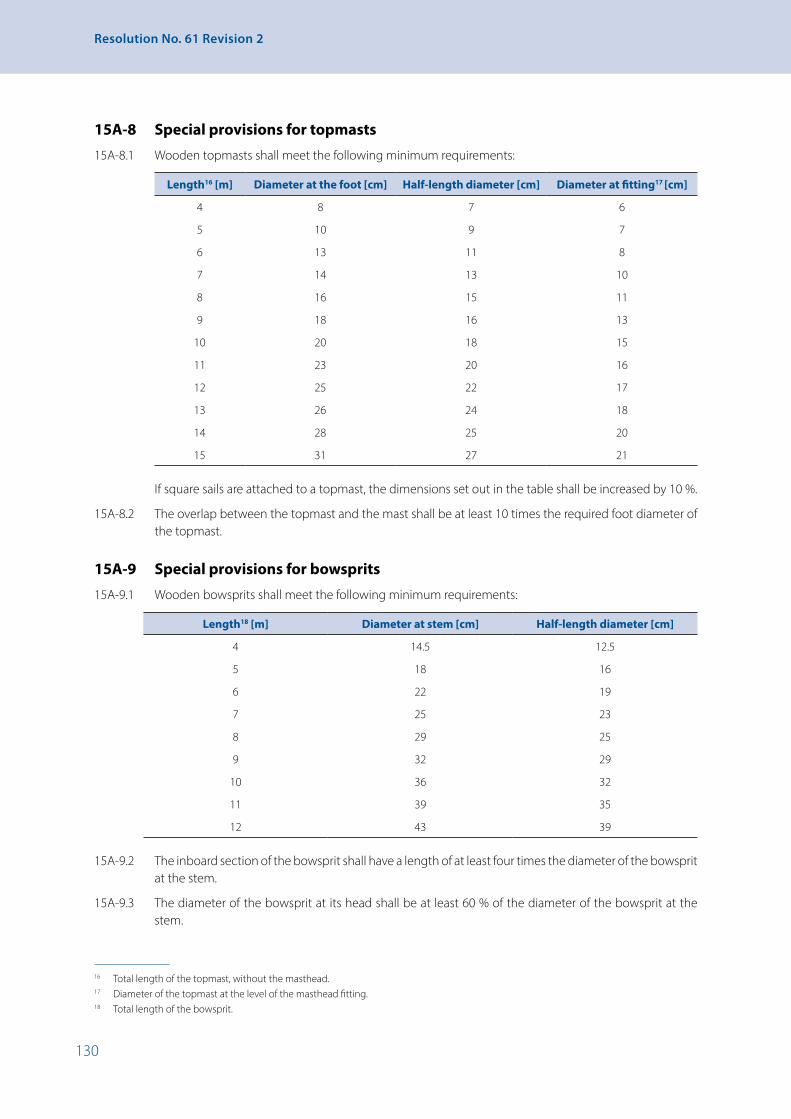
130
Resolution No. 61 Revision 2
15A-8 Special provisions for topmasts
15A-8.1 Wooden topmasts shall meet the following minimum requirements:
Length16 [m] Diameter at the foot [cm] Half-length diameter [cm] Diameter at fitting17 [cm]
4 8 7 6
5 10 9 7
6 13 11 8
7 14 13 10
8 16 15 11
9 18 16 13
10 20 18 15
11 23 20 16
12 25 22 17
13 26 24 18
14 28 25 20
15 31 27 21
If square sails are attached to a topmast, the dimensions set out in the table shall be increased by 10 %.
15A-8.2 The overlap between the topmast and the mast shall be at least 10 times the required foot diameter of the topmast.
15A-9 Special provisions for bowsprits
15A-9.1 Wooden bowsprits shall meet the following minimum requirements:
Length18 [m] Diameter at stem [cm] Half-length diameter [cm]
4 14.5 12.5
5 18 16
6 22 19
7 25 23
8 29 25
9 32 29
10 36 32
11 39 35
12 43 39
15A-9.2 The inboard section of the bowsprit shall have a length of at least four times the diameter of the bowsprit at the stem.
15A-9.3 The diameter of the bowsprit at its head shall be at least 60 % of the diameter of the bowsprit at the stem.
16 Total length of the topmast, without the masthead.17 Diameter of the topmast at the level of the masthead fitting.18 Total length of the bowsprit.

131
Chapter 15A - Specific Requirements for Sailing Passenger Vessels
15A-10 Special provisions for jib-booms
15A-10.1 Wooden jib-booms shall meet the following minimum requirements:
Length19 [m] 2 3 4 5 6 7 8 9 10
Diameter at the stem [cm] 7 10 14 17 21 24 28 31 35
15A-10.2 The diameter of the jib-boom at its head shall be at least 60 % of the diameter at the stem.
15A-11 Special provisions for main booms
15A-11.1 Wooden main booms shall meet the following minimum requirements:
Length20[m] 5 6 7 8 9 10 11 12 13 14 15 16
Diameter [cm] 14 15 16 17 18 20 21 23 24 25 26 27
15A-11.2 The diameter at the swivel pin shall be at least 72 % of the diameter specified in the table.
15A-11.3 The diameter at the clew shall be at least 85 % of the diameter specified in the table.
15A-11.4 Measured from the mast, the greatest diameter shall be at two thirds of the length.
15A-11.5 Where:
(i) there is an angle of less than 65° between the main boom and the after leech and the main sheet is attached to the end of the boom, or
(ii) the attachment point of the sheet is not abreast of the clew,
the competent authority may, according to paragraph 15A-5.2, require a greater diameter.
15A-11.6 For sail areas of less than 50 m2, the competent authority may authorise reductions in the dimensions set out in the table.
15A-12 Special provisions for gaffs
15A-12.1 Wooden gaffs shall meet the following minimum requirements:
Length21 [m] 4 5 6 7 8 9 10
Diameter [cm] 10 12 14 16 17 18 20
15A-12.2 The unsupported length of the gaff shall be not more than 75 %.
15A-12.3 The breaking strength of the crowfoot shall be at least equal to 1.2 times the breaking strength of the peak halyard.
15A-12.4 The top angle of the crowfoot shall be a maximum of 60°.
15A-12.5 If, by way of derogation from paragraph 15A-12.4, the top angle of the crowfoot is greater than 60°, the tensile strength shall be adjusted to accommodate the forces that will then occur.
15A-12.6 For sail areas of less than 50 m2, the competent authority may authorise reductions in the dimensions set out in the table.
19 Total length of the jib-boom.20 Total length of the main boom.21 Total length of the gaff.

132
Resolution No. 61 Revision 2
15A-13 General provisions for standing and running rigging
15A-13.1 Standing and running rigging shall comply with the strength requirements set out in sections 15A-14 and 15A-15.
15A-13.2 Wire cable connections may take the form of:
(i) splicings,
(ii) compression sleeves, or
(iii) sealing sleeves.
Splicings shall be marled and ends shall be whipped.
15A-13.3 Eye splices shall be provided with thimbles.
15A-13.4 Ropes shall be routed in such a way as not to obstruct entrances and companionways.
15A-14 Special provisions for standing rigging
15A-14.1 Forestays and shrouds shall meet the following minimum requirements:
Mast length22 [m] 11 12 13 14 15 16 17 18
Tensile strength of the forestay [kN] 160 172 185 200 220 244 269 294
Tensile strength of the shrouds [kN] 355 415 450 485 525 540 630 720
Number of shroud cables and ropes per side 3 3 3 3 3 3 4 4
15A-14.2 Backstays, topmasts, flying jib-stays, jib-booms and bowsprit shrouds shall meet the following minimum requirements:
Mast length23 [m] <13 13-18 >18
Tensile strength of the backstay [kN] 89 119 159
Tensile strength of the topmast [kN] 89 119 159
Length of topmast [m] < 6 6-8 > 8
Tensile strength of the flying jib-stay [kN] 58 89 119
Length of jib-boom [m] < 5 5-7 > 7
Tensile strength of the bow sprit shrouds [kN] 58 89 119
15A-14.3 The preferred rope design shall be based on Rope Construction Method 6 × 7 FE in the strength class 1550 N/mm2. Alternatively, at the same strength class, Construction Method 6 × 36 SE or 6 × 19 FE may be used. Because of the higher elasticity of Construction Method 6 × 19, the tensile strengths given in the table shall be increased by 10 %. Use of a different rope design shall be permitted provided it has comparable properties.
15A-14.4 If rigid rigging is used, the tensile strengths shown in the table shall be increased by 30 %.
15A-14.5 For rigging, only approved forks, round eyes and bolts may be used.
15A-14.6 Bolts, forks, round eyes and turnbuckles shall be capable of being properly secured.
15A-14.7 The tensile strength of the bobstay shall be at least 1.2 times the tensile strength of the respective jib-stay and flying jib-stay.
22 Distance from the top or cross-tree to the deck.23 Distance from the top or cross-tree to the deck.

133
Chapter 15A - Specific Requirements for Sailing Passenger Vessels
15A-14.8 For vessels with less than 30 m3 water displacement, the competent authority may permit the reductions in tensile strengths shown in the table set out below:
Water displacement divided by the number of masts [m3] Reduction [%]
> 20 to 30 20
10 to 20 35
< 10 60
15A-15 Special provisions for running rigging
15A-15.1 For running rigging, fibre ropes or steel wire ropes shall be used. The minimum tensile strength and the diameter for running rigging shall, in relation to the sail area, meet the following minimum requirements:
Type of running rigging Rope material Sail area [m2] Minimum tensile
strength [kN]Diameter of rope
[mm]
Staysail halyards Steel wire up to 35 20 6
> 35 38 8
Fibre (polypropylene-PP)
Rope diameter of at least 14 mm and one rope sheave for every 25 m2 or part thereof
Gaff sail halyardsTop sail halyards
Steel wire up to 50 20 6
> 50 to 80 30 8
> 80 to 120 60 10
>120 to 160 80 12
Fibre (PP) Rope diameter of at least 18 mm and one rope sheave for every 30 m2 or part thereof
Staysail sheets Fibre (PP) up to 40 14
> 40 18
For sail areas of more than 30 m2, the sheet shall take the form of a tackle or shall be capable of being operated by a winch
Gaff-/Top-sail sheets
Steel wire < 100 60 10
100 to 150 85 12
> 150 116 14
For top sail sheets, elastic connection elements (fore runners) are necessary
Fibre (PP) Rope diameter of at least 18 mm and at least three rope sheaves. Where the sail area is greater than 60 m2, one rope sheave per 20 m2
15A-15.2 Running rigging forming part of the staying shall have a tensile strength which corresponds to that of the respective stay or shrouds.
15A-15.3 If materials other than those stated in paragraph 15A-15.1 are used, the strength values given in the table in paragraph 15A-15.1 shall be complied with.
Fibre ropes of polyethylene shall not be used.
15A-16 Fittings and parts of the rigging
15A-16.1 If steel wire ropes or fibre ropes are used, the diameters of the rope sheaves (measured from centre of rope to centre of rope) shall meet the following minimum requirements:
Steel wire [mm] 6 7 8 9 10 11 12
Fibre [mm] 16 18 20 22 24 26 28
Rope sheave [mm] 100 110 120 130 145 155 165

134
Resolution No. 61 Revision 2
15A-16.2 By way of derogation from paragraph 15A-16.1, the diameter of the rope sheaves may be equal to six times the diameter of the steel wire, provided that the steel wire does not constantly run over sheaves.
15A-16.3 The tensile strength of the fittings (e.g. forks, round eyes, turnbuckles, eye-plates, bolts, rings and shackles) shall be compatible with the tensile strength of the standing or running rigging that is attached to them.
15A-16.4 The fastenings of stay and shroud futtocks shall be designed to take up the forces they are subjected to.
15A-16.5 Only one shackle, along with the relevant stay or shroud, may be attached to each eye.
15A-16.6 Blocks of halyards and topping lifts shall be securely fastened to the mast, and the revolving crowfeet used for this purpose shall be in good condition.
15A-16.7 Attachments of eye-bolts, cleats, belaying pins and fife-rails shall be designed to cope with the forces they are subjected to.
15A-17 Sails
15A-17.1 It shall be ensured that sails can be taken in simply, swiftly and safely.
15A-17.2 The sail area shall be appropriate for the type of vessel and the water displacement.
15A-18 Equipment
15A-18.1 Vessels that are fitted with a jib-boom or a bowsprit shall have a jib-net and an adequate number of appropriate holding and tensioning devices.
15A-18.2 The equipment according to paragraph 15A-18.1 may be dispensed with if the jib-boom or bowsprit is equipped with a hand becket and a foot rope adequately dimensioned to allow for the attachment of a safety harness to be carried on board.
15A-18.3 For work on the rigging, a boatswain’s chair shall be provided.
15A-19 Testing
15A-19.1 The rigging shall be tested by the competent authority every 2.5 years. As a minimum, the test shall cover the following:(i) The sails, including leeches, clews and reef eyes;(ii) The state of the masts and spars;(iii) The state of the standing and running rigging together with cable wire connections;(iv) Facilities for taking in the sail swiftly and safely;(v) The secure fastening of blocks of halyards and topping lifts;(vi) The fastening of mast trunks and other fastening points for standing and running rigging that are
attached to the vessel;(vii) The winches for operating the sails;(viii) Other facilities fitted for the purposes of sailing, such as lee-boards and the fittings for operating
them;(ix) The measures taken to prevent the chafing of the spars, the running and standing rigging and
the sails;(x) The equipment according to section 15A-18.
15A-19.2 That part of the wooden mast passing through the deck and located below the deck shall be re-examined at intervals to be determined by the competent authority, but at the very least on the occasion of each periodical inspection according to section 2-4. The mast shall be extracted for this purpose.
15A-19.3 A certificate of the last inspection carried out in accordance with paragraph 15A-19.1 and issued, dated and signed by the competent authority, shall be carried on board.

135
CHAPTER 16 - Specific Requirements Applicable to Vessels Intended to Form Part of a Pushed or Towed Convoy or of a Side-By-Side Formation
CHAPTER 16 - Specific Requirements Applicable to Vessels Intended to Form Part of a Pushed or Towed Convoy or of a Side-By-Side Formation
16-1 Vessels suitable for pushing
16-1.1 Vessels suitable for pushing shall have at the bow a suitable pushing device so designed and equipped that, from the start of the coupling manoeuvres:
(i) The vessel can take up a fixed position in relation to the pushed lighters;
(ii) The crew can perform easily and safely the manoeuvres required for coupling the vessel to the pushed lighters.
16-1.2 Vessels suitable for pushing shall be equipped with at least two special winches or equivalent coupling devices, which shall satisfy the following requirements:
(i) All components of the coupling device shall be capable of withstanding the maximum operational stresses imposed under the severest conditions to be encountered in the navigation zone for which the vessel is intended;
(ii) The coupling devices shall ensure the rigid coupling with the pushed vessel or vessels;
where convoys consist of a pusher vessel and a single pushed vessel, the coupling devices may permit controlled articulation. The control systems required for this purpose shall easily absorb the forces to be transmitted and shall be capable of being controlled easily and safely. Sections 6-2 to 6-4 shall apply by analogy to such control systems;
(iii) It shall be possible to couple the pusher vessel to both loaded and empty pushed lighters;
(iv) The coupling device shall be so positioned on deck as not to interfere with the operation of other deck mechanisms, and the parts of the coupling device shall not project beyond the vessel’s breadth over-all.
16-1.3 Vessels intended to propel side-by-side formations shall be equipped with bollards or equivalent devices the number and arrangement of which permit the formation to be securely linked.
16-2 Pushed lighters
16-2.1 Chapters 5, 6, 7, sections 8-1.6.2 to 8-1.6.8 of chapter 8, section 10-2 of chapter 10, and chapter 12 shall not apply to pushed lighters with no steering system, accommodation, engine room or boilers.
16-2.2 Ship-born barges having a length L of 40 m or less shall in addition meet the following construction requirements:
(i) The watertight transverse bulkheads referred to in paragraph 3-4.1 shall not be required if the forward side is capable of bearing a load at least 2.5 times that stipulated for the collision bulkhead of an inland waterway vessel with the same draught, built to the requirements of a recognized Classification Society;
(ii) Notwithstanding paragraph 8-1.6.1, double-bottomed compartments to which access is difficult only have to be drainable if their volume exceeds 5 % of the water displacement of the ship-born barge at the maximum authorized loaded draught.
16-2.3 Vessels intended for use in convoys shall be equipped with coupling devices, bollards or equivalent devices, the number and arrangement of which permit a secure link with other vessels or vessels of the convoy.

136
Resolution No. 61 Revision 2
16-3 Towing vessels
16-3.1 Vessels to be used for towing operations shall meet the following requirements:
(i) Towing equipment shall be arranged in such a way that its use does not impair the safety of the vessel, crew or the cargo;
(ii) Vessels to be used for auxiliary or main towing shall be equipped with towing devices: a towing winch or a tow hook which shall be capable of slipping, for the towing winch, or safe release, for the tow hook, from the steering position;
(iii) The towing devices shall be installed forward of the propeller plane. That requirement shall not apply to vessels steered by cycloidal propellers or similar propulsion units;
(iv) Notwithstanding the requirements of (ii) above, in the case of vessels to be used solely for auxiliary towing, other towing devices such as a bollard, to be installed forward of the propeller plane, may be used.
16-3.2 The Basin Administration may limit the length of the vessel to be used for downstream towing.
16-4 Tests on convoys of vessels
16-4.1 In order to issue the certificate of fitness of a pusher or a self-propelled vessel capable of propelling a rigid convoy, and to enter relevant particulars in the certificate, the competent authority shall decide whether and which convoys are to be presented to it for inspection and shall carry out the navigation tests referred to in section 5-2 with the convoy in the requested formation(s), which it considers to be least favourable. The convoy must meet the requirements set out in sections 5-2 to 5-10.
The competent authority shall check that the rigid coupling of all the vessels in the convoy is assured during the manoeuvres prescribed in chapter 5.
16-4.2 If, in the course of the tests referred to in section 16-4.1 above, special equipment installed on vessels that are being pushed or led side-by-side is used, such as propelling or manoeuvring installations or articulated couplings, in order to meet the requirements of sections 5-2 to 5-10, the following shall be mentioned in the certificate of the vessels propelling the convoy: the formation, its position, the name and official number of the vessels making part of the convoy and fitted with the special equipment used.
16-5 Entries on the certificate
16-5.1 If a vessel is intended to push a convoy, or to be pushed in a convoy, the certificate shall mention its compliance with the applicable requirements of sections 16-1 to 16-4 above.
16-5.2 The following particulars shall be entered in the certificate of the vessel intended to ensure propulsion of another vessel or a convoy:
(i) The convoys and formations permitted;
(ii) Types of coupling;
(iii) Maximum coupling forces transmitted; and
(iv) Where appropriate, minimum tensile strength of the coupling cables for the longitudinal connection and the number of turns of the cable on the bollard.
137
CHAPTER 17 - Specific Requirements Applicable to Floating Equipment
CHAPTER 17 - Specific Requirements Applicable to Floating Equipment
17-1 General
For construction and equipment of floating equipment chapters 3, 7 to 14 and 16 shall apply. Floating equipment with its own means of propulsion shall also meet the requirements of chapters 5 and 6. Propulsion units permitting only short-haul operation shall not constitute own means of propulsion.
17-2 Derogations
17-2.1 The Administration may grant derogations from the following requirements:
(i) Paragraphs 3-4.1.1 to 3-4.1.4 and 3-4.1.9 shall apply mutatis mutandis;
(ii) Section 7-2 shall apply mutatis mutandis;
(iii) The maximum sound pressure levels prescribed by paragraph 12-2.1.8, second sentence, may be exceeded while the floating equipment’s working gear is operating, provided that, during service, nobody sleeps on board at night;
(iv) Derogations may be granted from other requirements concerning structure, working gear or equipment provided that equal safety is ensured in each case.
17-2.2 The Administration may dispense with the application of the following requirements:
(i) Section 10-1, if during operation of floating equipment that equipment can be securely anchored by means of a working anchor or piles. However, floating equipment with its own means of propulsion shall have at least one anchor meeting the requirements of paragraph 10-1.2.1, where an empirical coefficient c is taken to be equal to 45, and the smallest height is taken for T, or of paragraph 10-1.2.2;
(ii) Paragraph 12-4.1, second part of sentence, if the accommodation can be adequately lit by means of electricity.
17-2.3 In addition, the following shall apply:
(i) For paragraph 8-1.6.2, second sentence, the bilge pump shall be motor driven;
(ii) For paragraph 8B-8.3, the noise may exceed 65 dB(A) at a lateral distance of 25 m from the vessel’s side of any stationary floating equipment while its working gear is operating;
(iii) For paragraph 10-3.1, at least one further portable extinguisher is required if working gear not permanently attached to the craft is placed on the deck. The extinguisher shall be located in the vicinity of this working gear;
(iv) For paragraph 14-2.2, in addition to the liquefied-gas equipment for domestic use, there may also be other liquefied-gas facilities. Those facilities and their accessories shall meet the requirements of the Administration.
17-3 Additional requirements
17-3.1 Floating equipment on which persons are present during operation shall be fitted with a general alarm system. The alarm signal shall be clearly distinguishable from other signals and, within accommodation and at all control centres, shall produce a sound pressure level that is at least 5 dB(A) higher than the maximum local sound pressure level. It shall be possible to actuate the alarm system from the wheelhouse and the main work stations.
17-3.2 Working equipment shall have sufficient strength to withstand the loads it is subjected to and shall meet the relevant requirements of the Administration.
138
Resolution No. 61 Revision 2
17-3.3 The stability (resistance to overbalancing) and strength of working equipment, and where appropriate its attachments, shall be such that it may withstand the forces resulting from the expected heel, trim and movement of the floating equipment.
17-3.4 If loads are lifted by means of hoists the maximum authorized load deriving from stability and strength shall be prominently displayed on panels on deck and at the control stations. If the lifting capacity can be increased by connecting additional floats the values authorized both with and without these additional floats shall be clearly stated.
17-4 Residual safety clearance
17-4.1 For the purposes of this chapter and by way of derogation from section 1-2, residual safety clearance means the shortest vertical distance between surface of the water and the lowest part of the floating equipment beyond which it is no longer watertight, taking into account trim and heel resulting from the moments referred to in paragraph 17-7.4.1.
17-4.2 The residual safety clearance is sufficient according to paragraph 17-7.1, for any spray-proof and weathertight aperture if it is at least 300 mm.
17-4.3 At an aperture that is not spray-proof and weathertight the residual safety clearance shall be at least 400 mm.
17-5 Residual freeboard
17-5.1 For the purposes of this chapter and by way of derogation from section 1-2, residual freeboard means the smallest vertical distance between the surface of the water and the upper surface of the deck at its edge taking into account trim and heel resulting from the moments referred to in paragraph 17-7.4.1.
17-5.2 The residual freeboard is sufficient according to paragraph 17-7.1, if it is at least 300 mm.
17-5.3 The residual freeboard may be reduced if it is proven that the requirements of section 17-8 have been met.
17-5.4 Where the shape of a float differs perceptibly from that of a pontoon, as in the case of a cylindrical float, or where the cross-section of a float has more than four sides, the Administration may require or authorize a residual freeboard that differs from paragraph 17–5.2. This shall also apply to floating equipment consisting of several floats.
17-6 Heeling test
17-6.1 Confirmation of stability according to sections 17-7 and 17-8 shall be based on a heeling test that has been carried out in a proper manner.
17-6.2 If during a heeling test it is not possible to achieve adequate heeling angles, or if the heeling test causes unreasonable technical difficulties, this may be replaced by a calculation of the craft’s centre of gravity and weight. The result of the weight calculation shall be checked by measuring the draught, and the difference shall not exceed ±5 %.
17-7 Confirmation of stability
17-7.1 It shall be confirmed that, when taking into account the loads applied during operation of the working gear and whilst under way, the residual freeboard and the residual safety clearance are sufficient. For that purpose the sum of the trim and heeling angles shall not exceed 10° and the bottom of the float shall not emerge.

139
CHAPTER 17 - Specific Requirements Applicable to Floating Equipment
17-7.2 Confirmation of stability shall include the following data and documents:
(i) Scale drawings of floats and working gear and the detailed data relating to these that are needed to confirm stability, such as content of the tanks, openings providing access to the inside of the vessel;
(ii) Hydrostatic data or curves;
(iii) Righting lever curves for static-stability to the extent required in accordance with subparagraph (v) below or section 17-8;
(iv) Description of the operating conditions together with the corresponding data concerning weight and centre of gravity, including its unladen state and the position of the working gear when the floating equipment is underway;
(v) Calculation of the heeling, trimming and righting moments, with a specification of the trim and heeling angles and the corresponding residual freeboard and residual safety clearances;
(vi) A compilation of the results of the calculation with a specification of the limits for operation and the maximum loads.
17-7.3 Confirmation of stability shall be based on at least the following load assumptions:
(i) Specific mass of the dredging products for dredgers:
• Sands and gravels: 1.5 t/m3
• Very wet sands: 2.0 t/m3
• Soil, on average: 1.8 t/m3
• Mixture of sand and water in the ducts: 1.3 t/m3;
(ii) For clamshell dredgers, the values given under point (i) shall be increased by 15 %;
(iii) For hydraulic dredgers the maximum lifting power shall be considered.
17-7.4 Confirmation of stability shall take account of the moments resulting from the operational conditions.
17-7.4.1 The above-mentioned moments to be taken into account shall include in any way the moments resulting from:
(i) Load;
(ii) Asymmetric structure;
(iii) Wind pressure;
(iv) Turning whilst under way of self-propelled floating equipment;
(v) Cross current, if necessary;
(vi) Ballast and provisions;
(vii) Deck loads and, where appropriate, cargo;
(viii) Free surfaces of liquids;
(ix) Inertia forces;
(x) Other mechanical equipment.
The moments which may act simultaneously shall be added up.
17-7.4.2 The moment caused by the wind pressure shall be calculated in accordance with the following formula:
𝑀𝑀𝑀𝑀w = 𝑐𝑐𝑐𝑐 × ρw × 𝐴𝐴𝐴𝐴 × �𝑙𝑙𝑙𝑙w +𝑇𝑇𝑇𝑇2� [kN × m],
where: c = shape-dependent coefficient of resistance. For frameworks c = 1.2 and for solid-section beams c = 1.6. Both values take account of gusts of wind. The whole area encompassed by the contour line of the framework shall be taken to be the surface area exposed to the wind. ρw – specific wind pressure, [kN/m2]; this shall uniformly be taken to be 0.25 kN/m2; A – lateral plane above the plane of maximum draught, [m2]; lw – distance from the centre of area of the lateral plane A from the plane of maximum draught, [m].
17-7.4.3 In order to determine the moments due to turning whilst under way according to subparagraph 17-7.4.1 (iv) for self-propelled floating equipment, the formula set out in section 15-3.6 shall be used.
17-7.4.4 The moment resulting from cross current according to subparagraph 17-7.4.1 (v) shall be taken into account only for floating equipment which is anchored or moored across the current while operating.
where: c = shape-dependent coefficient of resistance For frameworks c = 1.2 and for solid-section beams c = 1.6. Both values take account of gusts of wind.

140
Resolution No. 61 Revision 2
The whole area encompassed by the contour line of the framework shall be taken to be the surface area exposed to the wind.
ρw – specific wind pressure, [kN/m2]; this shall uniformly be taken to be 0.25 kN/m2;
A – lateral plane above the plane of maximum draught, [m2];
lw – distance from the centre of area of the lateral plane A from the plane of maximum draught, [m].
17-7.4.3 In order to determine the moments due to turning whilst under way according to subparagraph 17-7.4.1 (iv) for self-propelled floating equipment, the formula set out in section 15-3.6 shall be used.
17-7.4.4 The moment resulting from cross current according to subparagraph 17-7.4.1 (v) shall be taken into account only for floating equipment which is anchored or moored across the current while operating.
17-7.4.5 The least favourable extent of tank filling from the point of view of stability shall be determined and the corresponding moment introduced into the calculation when calculating the moments resulting from liquid ballast and liquid provisions according to subparagraph 17-7.4.1 (vi).
17-7.4.6 The moment resulting from inertia forces according to subparagraph 17-7.4.1 (ix) shall be given due consideration if the movements of the load and the working gear are likely to affect stability.
17-7.5 The righting moments for floats with vertical side walls may be calculated using the following formula:
Ma = 10 × D × MG × sin φ [kN × m],
where: MG – metacentric height, [m];
φ – heeling angle, [degrees].
That formula shall apply up to heeling angles of 10° or up to a heeling angle corresponding to immersion of the edge of the deck or emergence of the edge of the bottom; the smallest angle shall be decisive. The formula may be applied to slanting side walls up to heeling angles of 5°; the limit conditions set out in the sections 17-7.3 and 17-7.4 shall also apply. If the particular shape of the float(s) does not permit such simplification the righting lever curves according to subparagraph 17-7.2 (iii) shall be required.
17-8 Confirmation of stability in the case of reduced residual freeboard
If a reduced residual freeboard according to paragraph 17-5.3 is used, it shall be proven for all operating conditions that:
(i) After correction for the free surfaces of liquids, the metacentric height is not less than 0.15 m;
(ii) For heeling angles between 0 and 30°, there is a righting lever of at least
h = 0.30 - 0.28 × φn [m],
φn being the heeling angle from which the righting lever curve displays negative values (range of stability); it shall not be less than 20° or 0,35 rad and shall not be introduced into the formula for more than 30° or 0.52 rad, taking the radian (rad) (1° = 0.01745 rad) for the unit of φ°;
(iii) The sum of the trim and heeling angles does not exceed 10°;
(iv) A residual safety clearance meeting the requirements in section 17-4 remains;
(v) A residual freeboard of at least 0.05 m remains;

141
CHAPTER 17 - Specific Requirements Applicable to Floating Equipment
(vi) For heeling angles between 0 and 30°, a residual righting lever of at least
h = 0.20 - 0.23 × φn [m],
remains, where φn is the heeling angle from which the righting lever curve displays negative values; it shall not be introduced into the formula for more than 30° or 0.52 rad.
Residual righting lever means the maximum difference existing between 0° and 30° of heel between the righting lever curve and the heeling lever curve. If an opening towards the inside of the vessel is reached by the water at a heeling angle less than that corresponding to the maximum difference between the lever curves, the lever corresponding to that heeling angle shall be taken into account.
17-9 Draught marks and draught scales
Draught marks and draught scales shall be affixed in accordance with article 6 of the annex to the Convention on the Measurement of Inland Navigation Vessels of 15 February 1966.
17-10 Floating equipment without confirmation of stability
17-10.1 The application of sections 17-4 to 17-8 may be dispensed with for floating equipment:
(i) Whose working gear can in no way alter their heeling or trim, and
(ii) Where any displacement of the centre of gravity can be reasonably excluded.
17-10.2 However,
(i) At maximum load the safety clearance shall be at least 300 mm and the freeboard at least 150 mm;
(ii) For apertures which cannot be closed spray-proof and weathertight the safety clearance shall be at least 500 mm.
17-11 Attestation of a recognized classification society
The Administration may consider the requirements of sections 17-4 to 17-8 to be met by craft built in conformity with the rules of a recognized Classification Society, which shall be confirmed by an attestation of that Society.

143
CHAPTER 18 - Specific Requirements Applicable to Worksite Craft
CHAPTER 18 - Specific Requirements Applicable to Worksite Craft
18-1 General
18-1.1 Worksite craft designated as such in the ship’s certificate set out in appendix 2 may navigate outside worksites only when unladen. That restriction shall be entered on the ship’s certificate. For this purpose worksite craft shall have a certificate issued by the Administration indicating the duration of works and the geographical boundaries of the worksite in which the craft may be operated.
18-1.2 Unless otherwise specified in this chapter, the construction and equipment of worksite craft shall be in line with chapters 3 to 14.
18-2 Derogations
18-2.1 The Administration may grant derogations from the following requirements:
(i) Paragraphs 3-4.1.1 to 3-4.1.4 shall apply mutatis mutandis;
(ii) Chapters 5 and 6 shall apply mutatis mutandis where the craft is self-propelled;
(iii) Paragraph 10-1.4.5 shall apply mutatis mutandis;
(iv) the Administration may grant exceptions to the other requirements concerning construction, arrangement and equipment provided that equivalent safety is proven in every case.
18-2.2 The Administration may dispense with the following provisions:
(i) Paragraphs 8-1.6.2 to 8-1.6.8 if no crew is required;
(ii) Paragraphs 10-1.2.1 and 10-1.3.1 if the worksite craft can be securely anchored by means of working anchors or piles. However, self-propelled worksite craft shall be equipped with at least one anchor meeting the requirements set out in paragraph 10-1.2.1, where coefficient c is taken to be 45 and T is taken to be the lowest height, or in paragraph 10-1.2.2.
18-3 Safety clearance and freeboard
18-3.1 If a worksite craft is used as a reclamation barge or a hopper barge, the safety clearance outside the hold area shall be at least 300 mm and the freeboard at least 150 mm. The Administration may permit a smaller freeboard if proof by calculation is provided that stability is sufficient for a cargo having a specific mass of 1.5 t/m3 and that no side of the deck reaches the water. The effect of liquefied cargo shall be taken into account.
18-3.2 The provisions of section 4-4.4 shall apply mutatis mutandis to worksite craft not covered by paragraph 18-3.1. The Administration may determine values departing from the above for safety clearance and freeboard.
18-4 Attestation of a recognized classification society
The Administration may consider the requirements of section 18-3 to be met by craft built in conformity with the rules of a recognized Classification Society, which shall be confirmed by an attestation of that Society.
18-5 Ship’s boats
18-5.1 Worksite craft shall not be required to have a ship’s boat where:
(i) They are not self-propelled; or
(ii) A ship’s boat is available elsewhere on the worksite.
This derogation shall be entered on the ship’s certificate.

144
Resolution No. 61 Revision 2
CHAPTER 19 - Specific Requirements Applicable to Historic Vessels
(Left void)

145
CHAPTER 19A - Specific Requirements Applicable to Canal Barges
CHAPTER 19A - Specific Requirements Applicable to Canal Barges
(Left void)

146
Resolution No. 61 Revision 2
CHAPTER 19B - Subjects for Possible Reductions of the Technical Requirements Applicable to Craft on Inland Waterways of Zones 3 and 419-1 Each Basin Administration may allow a reduction of the technical requirements of these
recommendations for vessels operating exclusively on zone 3 or zone 4 waterways on the territory of that Basin Administration. The reductions are restricted to the following subjects:
(i) Zone 3:
• Anchor equipment, including length of anchor chains;
• (Forward) speed;
• Collective life-saving appliances;
• Two-compartment status;
• Wheelhouse visibility;
(ii) Zone 4:
• Anchor equipment, including length of anchor chains;
• (Forward) speed;
• Life-saving appliances;
• Two-compartment status;
• Wheelhouse visibility;
• Second independent propulsion system.

147
CHAPTER 20 - Specific Requirements Applicable to Sea-Going Ships
CHAPTER 20 - Specific Requirements Applicable to Sea-Going Ships
20-1 General
20-1.1 Sea-going ships covered by the International Convention for the Safety of Life at Sea of 1974 (SOLAS 1974) or the International Convention on Load Lines of 1966 shall carry a valid corresponding international certificate.
20-1.2 Sea-going ships not covered by SOLAS 1974 or the International Convention of Load Lines 1966 must carry the certificates and bear the freeboard marks required by the laws of their States of registry, and shall meet the requirements of the Convention in respect of construction, rigging and gear, or otherwise ensure a comparable safety level.
20-1.3 Sea-going ships covered by the International Convention for the Prevention of Pollution from Ships of 1973 (MARPOL 73) shall carry a valid international oil pollution prevention certificate (IOPP certificate).
20-1.4 Sea-going ships not covered by MARPOL 73 shall carry a valid corresponding certificate required by the laws of their flag State.
20-1.5 In addition, the following shall be applicable:
(i) Chapter 5;
(ii) From chapter 6: Articles 6-1.1, 6-2.1, 6-2.2;
(iii) From chapter 7: Article 7-1.5, article 7-2.1, article 7-2.2, paragraphs 1 and 4, article 7-6.7 for sea-going ships approved for radar-steering by one person;
(iv) From chapters 8 and 8B: Article 8-1.1.6 for sea-going ships, when an automatic shutdown can be deactivated from
the wheelhouse; article 8-1.5.12, article 8B-1.5, articles 8B-1.2 and 8B-1.6 and article 8B-8. A seal for the closing devices required under article 8B-1.5 shall be considered equivalent to a shut-off for the closing devices of the drainage system for pumping oily water overboard. The necessary key or keys shall be kept in a properly marked central location. An oil discharge monitoring and control system in accordance with regulation 16 of MARPOL 73/78 shall be considered to be equivalent to the sealing of closing devices prescribed in article 8B-1.5. An international certificate concerning the prevention of oil pollution in accordance with MARPOL 73/78 shall provide evidence of the presence of the monitoring and control system. If it is indicated in the IOPP certificate mentioned under 20-1.3, above, or the national certificate issued by the State of registry mentioned under 20-1.4 above, that the ship is equipped with waste tanks sufficient to hold on board all oily water and residues, it shall be considered that there is compliance with article 8B-1.6;
(v) From chapter 9: Article 9-2.14;
(vi) From chapter 10: Section 10-1 (except 10-1.2.2 and 10-1.3.3) and article 10-2.1;
(vii) Chapter 16, for sea-going ships approved as part of a convoy;
(viii) Chapter 22: Chapter 22 shall be considered to have been complied with when stability is in conformity with
the resolutions of the International Maritime Organization (IMO) in force, when the relevant documents relating to stability have been stamped by the competent authority and when the containers are secured in the manner usual in maritime shipping.

148
Resolution No. 61 Revision 2
20-2 Minimum crew
20-2.1 Chapter 23 shall apply in determining the minimum crew for sea-going ships.
20-2.2 As an exception to 20-2.1, sea-going ships may continue to sail with the crew arrangements set out in the provisions of IMO resolution A.481 (XII) and the International Convention on Standards of Training, Certification and Watchkeeping for Seafarers of 1978, provided that the number of the crew is not less than the minimum crew detailed in chapter 23 for operating mode B, and particularly articles 23-9 and 23-13.
The relevant documents, which set out the qualifications of crew members and their number, shall be kept on board. A person in possession of the boatmaster’s certificate, valid for the section travelled, shall also be on board. The boatmaster shall be replaced by another boatmaster certificate-holder after a maximum of 14 hours’ navigation in any 24-hour period. The following particulars shall be entered in the ship’s log:
(i) Name of the boatmaster certificate-holders on board, along with the beginning and end of their watch;
(ii) Beginning and interruption, resumption and end of the voyage, with the following particulars: date, time and place and kilometre post.
149
CHAPTER 20B - Special Provisions Applicable to River-Sea Navigation Vessels
CHAPTER 20B - Special Provisions Applicable to River-Sea Navigation Vessels
20В-1 General provisions
20B-1.1 Purpose and scope
20В-1.1.1 For the purpose of this chapter, the following zones and conditions of sea navigation shall be established:
(i) Restricted zone between ports of the same country (domestic voyages) where inland navigation vessels are allowed to navigate with season and wave height restrictions provided that specific requirements of the Administration or a recognized classification society concerning seaworthiness, stability, hull structure, machinery, electrical equipment, navigation equipment and communication facilities are met.
(ii) zone RS 2,0 (wave height up to 2.0 m):24 sea areas within specified geographical borders where river-sea navigation vessels are allowed to navigate with season restrictions;
(iii) zone RS 3,0 (wave height up to 3.0 m): sea areas within specified geographical borders where river-sea navigation vessels are allowed to navigate with season restrictions;
(iv) zone RS 3,5 (wave height up to 3.5 m): sea areas within specified geographical borders where river-sea navigation vessels are allowed to navigate with season restrictions;
(v) zone RS 4,5 (wave height up to 4.5 m): sea areas where river-sea navigation vessels are allowed to navigate in closed seas away from shelter at a distance up to 100 miles (distance between shelters up to 200 miles); in open seas away from shelter at a distance up to 50 miles (distance between shelters up to 100 miles);
(vi) zone RS 6,0 (wave height up to 6.0 m): sea areas where river-sea navigation vessels are allowed to navigate in closed seas away from shelter at a distance up to 100 miles (distance between shelters up to 200 miles); in open seas away from shelter at a distance up to 50 miles (distance between shelters up to 100 miles).
20В-1.1.2 Unless specified otherwise, the provisions of the present chapter apply to new vessels.
20B-1.2 Definitions
1. “River-sea navigation vessel”: a vessel intended for navigation on inland waterways and suitable for restricted navigation at sea.
2. “International voyage”: a voyage from a port of a country to which international conventions apply to a port outside such country or inverse.
3. “Coastal voyage”: any voyage other than an international voyage.
4. “Closed seas”: inland and mediterranean isolated seas communicating with ocean high-seas through straits and different from high seas in salinity and temperature of water, nature of currents, tides, wind and wave conditions.
5. “Main seas (open seas)”: off-lying seas with ample communication to ocean high-seas and water closely resembling that of high-seas in its salinity and temperature of water, nature of currents, tides, wind and wave conditions.
24 In the present chapter wave height means a wave height of 3 % probability.

150
Resolution No. 61 Revision 2
20B-1.3 Classification
River-sea vessels navigation vessels shall be built under the supervision of a recognized Classification Society in accordance with its classification requirements. The class assigned by the Classification Society shall be maintained for the whole operation period of the vessel.
20В-2 Documents
20В-2.1 River-sea navigation vessels involved in international voyages shall be covered by SOLAS 1974 or the International Convention on Load Lines of 1966 and shall carry a valid corresponding international certificate.
20В-2.2 River-sea navigation vessels involved in coastal voyages must carry the certificates required by the laws of their state of registry.
20В-2.3 River-sea navigation vessels involved in international voyages shall be covered by MARPOL 73 and shall carry a valid international sea pollution prevention certificate (IOPP certificate).
20В-2.4 River-sea navigation vessels involved in coastal voyages shall carry a valid sea pollution prevention certificate as required by the laws of their flag state.
20В-2.5 In addition to chapter 8A, river-sea navigation vessels involved in international voyages shall be covered by annex VI of MARPOL 73 and shall carry a valid international air prevention pollution certificate (IAPP Certificate).
20В-2.6 River-sea navigation vessels involved in coastal voyages shall comply with the requirements of the international Conventions and IMO instruments below:
(i) All types of vessels for navigation in all zones, except restricted zones:
• In addition to chapter 3A, the structural fire protection shall comply with chapter II–2 of SOLAS 1974 and International Code for Fire Safety Systems;
• In addition to chapter 4, the load line shall comply with International Convention on Load Lines, 1966;
• In addition to chapter 6, the electrical equipment shall comply with part D chapter II–1 of SOLAS 1974;
(ii) Self-propelled vessels for navigation in all zones, except restricted zone:
• the composition of communication equipment shall comply with chapter IV of SOLAS 1974 to ensure participation in Global Maritime Distress and Safety System (GMDSS);
• the composition of navigation equipment shall comply with chapter V of SOLAS 1974;
(iii) Passenger vessels in zone RS 3,0 and all vessels when navigating in zones RS 4,5, RS 6,0:
• In addition to chapters 3 and 15, the subdivision of the vessel shall comply with SOLAS 1974;
• The minimal summer freeboard for navigation at sea shall comply with International Convention on Load Lines, 1966;
• In addition to the chapters 10 and 15, life-saving appliances shall comply with SOLAS 1974 and the International Life-Saving Appliance Code, 1996;
• In addition to the ADN liquid cargo systems of oil tankers, air- and gas outlet ducts, ventilation, fire extinguishing, fuel and oil systems shall comply with SOLAS 1974 and the International Code for Fire Safety Systems.

151
CHAPTER 20B - Special Provisions Applicable to River-Sea Navigation Vessels
20В-3 Hull
20B-3.1 Strength
20В-3.1.1 In addition to chapter 3 the hull shall be designed in accordance with the rules of a recognized Classification Society and constructed under its supervision. The classification certificate shall specify for which zone(s) the vessel is fit.
20В-3.1.2 The bow draft of cargo vessels for any loading conditions shall not be less than specified in the table:
Zone Length of the vessel [m] Bow draft, not less than [m]
RS 2,0≤ 25 0.5
≥ 60 0.9
RS 3,0≤ 25 0.75
≥ 60 1.4
RS 3,5≤ 25 0.9
≥ 60 1.7
RS 4,5≤ 25 1.2
≥ 60 2.2
RS 6,0≤ 25 1.6
≥ 60 2.9
Note: Minimal permissible bow draft for vessels of transitional lengths shall be determined from linear interpolation.
20B–3.2 Design requirements
20В–3.2.1 Without prejudice to MARPOL 73 and ADN, motor vessels, lighters and barges shall have double sides and a double bottom. The double sides shall extend over the length of the cargo holds. The double bottom shall extend from the collision bulkhead to the aft peak bulkhead.
20В–3.2.2 Tankers for transportation of oil products, liquid dangerous goods and liquefied gases shall be fitted with facilities which enable safe access to the bow area.
20B-3.3 Stability
20В-3.3.1 In addition to 3-3.2.3, a vessel engaged in international voyages shall carry the Stability Booklet in English.
20В-3.3.2 In addition to 3-5.1.6, stability shall be checked under the most adverse loading conditions with due regard to 3-5.1.5, at least for the following cases:
(i) With full cargo and full stores;
(ii) With full cargo and 10 % stores;
(iii) With no cargo yet with ballast and full stores.
20В-3.3.3 In addition to 3-3.2.1, each vessel after restoring repair, major repair or modernization shall undergo a heeling test.
20B–3.4 Subdivision
20В–3.4.1 Vessels shall comply with 20B-2.6.

152
Resolution No. 61 Revision 2
20В-3.4.2 For vessels involved in coastal voyages it shall be ensured that the deck will not be submerged in any of the following situations:
(i) For passenger vessels in zone RS 2,0, when any two compartments are flooded;
(ii) For self-propelled flush-deck vessels, flush-deck barges and lighters in zones RS 3,5, RS 3,0 and RS 2,0, when any single compartment is flooded;
(iii) For motor cargo vessels in zone RS 3,5, when the forepeak, the afterpeak or any single double-bottom or double-side compartment is flooded.
20В-3.4.3 In addition to 3-4.1.3, the collision bulkhead shall be fitted at a distance of at least half of the hull width, aft of the forward perpendicular. For vessels more than 14 m wide this distance may be reduced on approval of the Administration or a recognized Classification Society.
20В-3.4.4 River-sea vessels shall be provided with a Stability Booklet and a damage control plan approved by the Administration or a recognized Classification Society.
20B-3.5 Stability criteria; weather criterion
20В-3.5.1 The vessel’s stability is regarded as sufficient as regards weather criterion if, at combined effects of wind and rolling, the requirements of the “Code on Intact Stability for all types of ships” are met with due regard to 20В-3.5.2.
20В-3.5.2 The initial metacentric height corrected for the free-surface effect of liquid cargo shall be at least 0.15 m for all types of vessels at any options of loading (except “unladen vessel”).
The minimal corrected metacentric height may have another value as in cases specified in 20В-3.6.
20B-3.6 Additional stability requirements for specific vessel types
20В-3.6.1 Motor cargo vessels
(i) The stability of vessels carrying cargo on deck shall be checked with additional loading options:
• With holds filled by homogeneous cargo having a draft according to the summer load line, with cargo on deck, full stores and liquid ballast, if necessary;
• Loaded as in the previous case but with 10 % of stores.
(ii) The metacentric height of vessels carrying cargo in bulk or on deck shall be at least 0.2 m.
(iii) As long as there no data on the stowage rate (μ), the stability of vessels carrying timber in the holds or on deck shall be determined at minimal value μ=2.32 m3/t.
20В-3.6.2 Vessels carrying containers
The stability of vessel carrying containers shall be checked for the following additional loading conditions:
• With the maximum number of containers each having a weight equal to 0.6 of the maximal gross weight for each type of container, and with full stores and liquid ballast, if necessary;
• Loaded as in the previous case but with 10 % of stores;
• With the maximum number of empty containers, with ballast and full stores;
• Loaded as in the previous case but with 10 % of stores.
20В-3.6.3 Tugs
(i) In addition to 3-5.3.3.1, the stability of tugs shall be checked at the following loading conditions:
• With full stores,
• With 10 % of stores.

153
CHAPTER 20B - Special Provisions Applicable to River-Sea Navigation Vessels
(ii) Tug shall be checked for stability under the dynamic effect of a towline jerk with due account for rolling, i.e. the following condition shall be met:
∆ × g × (dperm – dk) ≥ Mp,
where: Мр – heeling moment from dynamic effect of the towline jerk, [kN·m]; Мр is determined as per requirements set by the Administration or a recognized Classification Society;
Δ – displacement, [t];
g – acceleration of gravity (g = 9.81 m/s2);
dperm – lever of permissible moment taken from the dynamic stability curve, at the admissible heeling angle, [m];
dk – lever of permissible moment taken from the dynamic stability curve under estimated roll amplitude.
(iii) Tugs shall be checked for stability of towline jerks with no account taken of the free-surface effects from liquid cargo.
20В-3.6.4 Towed barges
(Left void)
20B-3.6.5 Icing
For vessels operating in subzero weather conditions, icing shall be taken into account in the stability calculations.
20В-4 Fire protection20В-4.1 Vessels shall comply with 20B-2.6.
20В-4.2 Fire-protection diagrams shall be provided on self-propelled vessels in the central control station, wheelhouse and on prominent places in the corridors. A second copy of fire-protection diagram or a booklet with such diagrams shall be kept outside the deckhouse in an assigned place protected against sea impact.
20B-5 Freeboard and load line
20B-5.1 Freeboard
20В-5.1.1 When assigning the minimum summer freeboard, the requirements of 20B-2.6 shall be met.
20B-5.1.2 For vessels engaged in coastal voyages in zones RS 3,5 (other than passenger vessels), RS 3,0, and RS 2,0 the minimum freeboard shall be assigned according to the requirements of the Administration or a recognized classification society.
20B-5.1.3 For vessels also designated for zones 1, 2 and 3, in addition the minimum freeboard shall be assigned in accordance with 4-4.2 and 4-4.4.
20В-5.1.4 Vessels navigating at sea shall carry a load line mark according to the International Convention on Load Lines, 1966.
The following marks shall be placed sternwards, off the draught mark:
(i) Marks for navigation on inland waterways of zones 1, 2 and 3 in accordance with 4-4.1.2;
(ii) A measurement mark in accordance with the requirements of the Convention on the Measurement of Inland Navigation Vessels, if the vessel is measured in accordance with it;
(iii) Marks for navigation in sea areas with seawater, where the vessel is allowed for navigation with a wave height lower than in the given zones, e.g. for a vessel in zone RS 3,5 – zones RS 3,0 and 2,0.
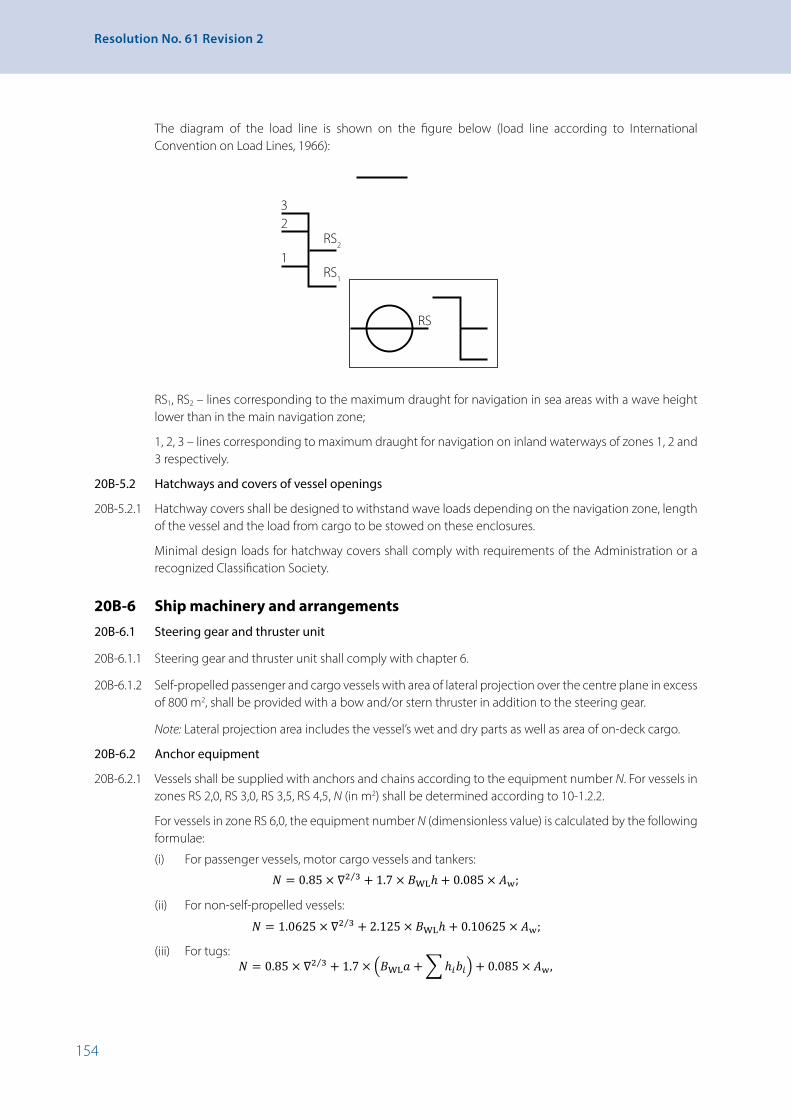
154
Resolution No. 61 Revision 2
RS1, RS2 – lines corresponding to the maximum draught for navigation in sea areas with a wave height lower than in the main navigation zone;
1, 2, 3 – lines corresponding to maximum draught for navigation on inland waterways of zones 1, 2 and 3 respectively.
20B-5.2 Hatchways and covers of vessel openings
20В-5.2.1 Hatchway covers shall be designed to withstand wave loads depending on the navigation zone, length of the vessel and the load from cargo to be stowed on these enclosures.
Minimal design loads for hatchway covers shall comply with requirements of the Administration or a recognized Classification Society.
20B-6 Ship machinery and arrangements
20B-6.1 Steering gear and thruster unit
20B-6.1.1 Steering gear and thruster unit shall comply with chapter 6.
20B-6.1.2 Self-propelled passenger and cargo vessels with area of lateral projection over the centre plane in excess of 800 m2, shall be provided with a bow and/or stern thruster in addition to the steering gear.
Note: Lateral projection area includes the vessel’s wet and dry parts as well as area of on-deck cargo.
20B-6.2 Anchor equipment
20B-6.2.1 Vessels shall be supplied with anchors and chains according to the equipment number N. For vessels in zones RS 2,0, RS 3,0, RS 3,5, RS 4,5, N (in m2) shall be determined according to 10-1.2.2.
For vessels in zone RS 6,0, the equipment number N (dimensionless value) is calculated by the following formulae:
(i) For passenger vessels, motor cargo vessels and tankers:
20B-6.2 Anchor equipment
20B-6.2.1 Vessels shall be supplied with anchors and chains according to the equipment number N. For vessels in zones RS 2,0, RS 3,0, RS 3,5, RS 4,5, N (in m2) shall be determined according to 10-1.2.2. For vessels in zone RS 6,0, the equipment number N (dimensionless value) is calculated by the following formulae: (i) For passenger vessels, motor cargo vessels and tankers:
𝑁𝑁𝑁𝑁 = 0.85 × ∇2 3⁄ + 1.7 × 𝐵𝐵𝐵𝐵WLℎ + 0.085 × 𝐴𝐴𝐴𝐴w; (ii) For non-self-propelled vessels:
𝑁𝑁𝑁𝑁 = 1.0625 × ∇2 3⁄ + 2.125 × 𝐵𝐵𝐵𝐵WLℎ + 0.10625 × 𝐴𝐴𝐴𝐴w; (iii) For tugs:
𝑁𝑁𝑁𝑁 = 0.85 × ∇2 3⁄ + 1.7 × �𝐵𝐵𝐵𝐵WL𝑎𝑎𝑎𝑎 + �ℎ𝑖𝑖𝑖𝑖𝑏𝑏𝑏𝑏𝑖𝑖𝑖𝑖� + 0.085 × 𝐴𝐴𝐴𝐴w,
where ∇ – water displacement corresponding to the summer load line, [m3]; BWL – breadth of waterline of the vessel, [m]; Aw – lateral plane within the vessel’s length LWL as per summer load waterline, [m2]. When calculating Аw, only the lateral plane of the hull as well as superstructures and deckhouses with a width over 0.25 BWL should be considered; h – distance from the summer load waterline to the upper edge of the deck plating of the highest deckhouse calculated by the formula, [m]:
ℎ = 𝑎𝑎𝑎𝑎 + �ℎ𝑖𝑖𝑖𝑖 ,
а – distance from the summer load waterline to the upper edge of the deck plating of the upper deck near the side amidships, [m]; hi – height of each layer of superstructure or deckhouse having a width over 0.25 BWL at the centre line of the vessel. In case of two or more superstructures or deckhouses in the given layer, only the superstructure or deckhouse of the biggest width should be considered. In the lowest layer, hi is measured in the centre line from the upper deck or, if the upper deck is stepped, from a horizontal line being the prolongation of the upper deck; bi – width of each (ith) layer of the superstructure or deckhouse having a width over 0.25 BWL, [m]. Sheer and trim may not be considered in calculations of h. Masts, cargo derricks, rigging, guard rails and similar structures as well as bulwark and hatch coamings less than 1.5 m high may be omitted in the calculations of h and Аw. If the height of bulwark or hatch coamings is over 1.5 m, they shall be considered as a deckhouse or superstructure.
20B-6.2.2 Vessels with N exceeding 75 m2 shall be fitted with two bow anchors. For vessels with N of 75 m2 or less one bow anchor is permitted.
(ii) For non-self-propelled vessels:
20B-6.2 Anchor equipment
20B-6.2.1 Vessels shall be supplied with anchors and chains according to the equipment number N. For vessels in zones RS 2,0, RS 3,0, RS 3,5, RS 4,5, N (in m2) shall be determined according to 10-1.2.2. For vessels in zone RS 6,0, the equipment number N (dimensionless value) is calculated by the following formulae: (i) For passenger vessels, motor cargo vessels and tankers:
𝑁𝑁𝑁𝑁 = 0.85 × ∇2 3⁄ + 1.7 × 𝐵𝐵𝐵𝐵WLℎ + 0.085 × 𝐴𝐴𝐴𝐴w; (ii) For non-self-propelled vessels:
𝑁𝑁𝑁𝑁 = 1.0625 × ∇2 3⁄ + 2.125 × 𝐵𝐵𝐵𝐵WLℎ + 0.10625 × 𝐴𝐴𝐴𝐴w; (iii) For tugs:
𝑁𝑁𝑁𝑁 = 0.85 × ∇2 3⁄ + 1.7 × �𝐵𝐵𝐵𝐵WL𝑎𝑎𝑎𝑎 + �ℎ𝑖𝑖𝑖𝑖𝑏𝑏𝑏𝑏𝑖𝑖𝑖𝑖� + 0.085 × 𝐴𝐴𝐴𝐴w,
where ∇ – water displacement corresponding to the summer load line, [m3]; BWL – breadth of waterline of the vessel, [m]; Aw – lateral plane within the vessel’s length LWL as per summer load waterline, [m2]. When calculating Аw, only the lateral plane of the hull as well as superstructures and deckhouses with a width over 0.25 BWL should be considered; h – distance from the summer load waterline to the upper edge of the deck plating of the highest deckhouse calculated by the formula, [m]:
ℎ = 𝑎𝑎𝑎𝑎 + �ℎ𝑖𝑖𝑖𝑖 ,
а – distance from the summer load waterline to the upper edge of the deck plating of the upper deck near the side amidships, [m]; hi – height of each layer of superstructure or deckhouse having a width over 0.25 BWL at the centre line of the vessel. In case of two or more superstructures or deckhouses in the given layer, only the superstructure or deckhouse of the biggest width should be considered. In the lowest layer, hi is measured in the centre line from the upper deck or, if the upper deck is stepped, from a horizontal line being the prolongation of the upper deck; bi – width of each (ith) layer of the superstructure or deckhouse having a width over 0.25 BWL, [m]. Sheer and trim may not be considered in calculations of h. Masts, cargo derricks, rigging, guard rails and similar structures as well as bulwark and hatch coamings less than 1.5 m high may be omitted in the calculations of h and Аw. If the height of bulwark or hatch coamings is over 1.5 m, they shall be considered as a deckhouse or superstructure.
20B-6.2.2 Vessels with N exceeding 75 m2 shall be fitted with two bow anchors. For vessels with N of 75 m2 or less one bow anchor is permitted.
(iii) For tugs:
20B-6.2 Anchor equipment
20B-6.2.1 Vessels shall be supplied with anchors and chains according to the equipment number N. For vessels in zones RS 2,0, RS 3,0, RS 3,5, RS 4,5, N (in m2) shall be determined according to 10-1.2.2. For vessels in zone RS 6,0, the equipment number N (dimensionless value) is calculated by the following formulae: (i) For passenger vessels, motor cargo vessels and tankers:
𝑁𝑁𝑁𝑁 = 0.85 × ∇2 3⁄ + 1.7 × 𝐵𝐵𝐵𝐵WLℎ + 0.085 × 𝐴𝐴𝐴𝐴w; (ii) For non-self-propelled vessels:
𝑁𝑁𝑁𝑁 = 1.0625 × ∇2 3⁄ + 2.125 × 𝐵𝐵𝐵𝐵WLℎ + 0.10625 × 𝐴𝐴𝐴𝐴w; (iii) For tugs:
𝑁𝑁𝑁𝑁 = 0.85 × ∇2 3⁄ + 1.7 × �𝐵𝐵𝐵𝐵WL𝑎𝑎𝑎𝑎 + �ℎ𝑖𝑖𝑖𝑖𝑏𝑏𝑏𝑏𝑖𝑖𝑖𝑖� + 0.085 × 𝐴𝐴𝐴𝐴w,
where ∇ – water displacement corresponding to the summer load line, [m3]; BWL – breadth of waterline of the vessel, [m]; Aw – lateral plane within the vessel’s length LWL as per summer load waterline, [m2]. When calculating Аw, only the lateral plane of the hull as well as superstructures and deckhouses with a width over 0.25 BWL should be considered; h – distance from the summer load waterline to the upper edge of the deck plating of the highest deckhouse calculated by the formula, [m]:
ℎ = 𝑎𝑎𝑎𝑎 + �ℎ𝑖𝑖𝑖𝑖 ,
а – distance from the summer load waterline to the upper edge of the deck plating of the upper deck near the side amidships, [m]; hi – height of each layer of superstructure or deckhouse having a width over 0.25 BWL at the centre line of the vessel. In case of two or more superstructures or deckhouses in the given layer, only the superstructure or deckhouse of the biggest width should be considered. In the lowest layer, hi is measured in the centre line from the upper deck or, if the upper deck is stepped, from a horizontal line being the prolongation of the upper deck; bi – width of each (ith) layer of the superstructure or deckhouse having a width over 0.25 BWL, [m]. Sheer and trim may not be considered in calculations of h. Masts, cargo derricks, rigging, guard rails and similar structures as well as bulwark and hatch coamings less than 1.5 m high may be omitted in the calculations of h and Аw. If the height of bulwark or hatch coamings is over 1.5 m, they shall be considered as a deckhouse or superstructure.
20B-6.2.2 Vessels with N exceeding 75 m2 shall be fitted with two bow anchors. For vessels with N of 75 m2 or less one bow anchor is permitted.
1
23
RS2
RS1
RS
The diagram of the load line is shown on the figure below (load line according to International Convention on Load Lines, 1966):

155
CHAPTER 20B - Special Provisions Applicable to River-Sea Navigation Vessels
where ∇ – water displacement corresponding to the summer load line, [m3];
BWL – breadth of waterline of the vessel, [m];
Aw – lateral plane within the vessel’s length LWL as per summer load waterline, [m2]. When calculating Аw, only the lateral plane of the hull as well as superstructures and deckhouses with a width over 0.25 BWL should be considered;
h – distance from the summer load waterline to the upper edge of the deck plating of the highest deckhouse calculated by the formula, [m]:
20B-6.2 Anchor equipment
20B-6.2.1 Vessels shall be supplied with anchors and chains according to the equipment number N. For vessels in zones RS 2,0, RS 3,0, RS 3,5, RS 4,5, N (in m2) shall be determined according to 10-1.2.2. For vessels in zone RS 6,0, the equipment number N (dimensionless value) is calculated by the following formulae: (i) For passenger vessels, motor cargo vessels and tankers:
𝑁𝑁𝑁𝑁 = 0.85 × ∇2 3⁄ + 1.7 × 𝐵𝐵𝐵𝐵WLℎ + 0.085 × 𝐴𝐴𝐴𝐴w; (ii) For non-self-propelled vessels:
𝑁𝑁𝑁𝑁 = 1.0625 × ∇2 3⁄ + 2.125 × 𝐵𝐵𝐵𝐵WLℎ + 0.10625 × 𝐴𝐴𝐴𝐴w; (iii) For tugs:
𝑁𝑁𝑁𝑁 = 0.85 × ∇2 3⁄ + 1.7 × �𝐵𝐵𝐵𝐵WL𝑎𝑎𝑎𝑎 + �ℎ𝑖𝑖𝑖𝑖𝑏𝑏𝑏𝑏𝑖𝑖𝑖𝑖� + 0.085 × 𝐴𝐴𝐴𝐴w,
where ∇ – water displacement corresponding to the summer load line, [m3]; BWL – breadth of waterline of the vessel, [m]; Aw – lateral plane within the vessel’s length LWL as per summer load waterline, [m2]. When calculating Аw, only the lateral plane of the hull as well as superstructures and deckhouses with a width over 0.25 BWL should be considered; h – distance from the summer load waterline to the upper edge of the deck plating of the highest deckhouse calculated by the formula, [m]:
ℎ = 𝑎𝑎𝑎𝑎 + �ℎ𝑖𝑖𝑖𝑖 ,
а – distance from the summer load waterline to the upper edge of the deck plating of the upper deck near the side amidships, [m]; hi – height of each layer of superstructure or deckhouse having a width over 0.25 BWL at the centre line of the vessel. In case of two or more superstructures or deckhouses in the given layer, only the superstructure or deckhouse of the biggest width should be considered. In the lowest layer, hi is measured in the centre line from the upper deck or, if the upper deck is stepped, from a horizontal line being the prolongation of the upper deck; bi – width of each (ith) layer of the superstructure or deckhouse having a width over 0.25 BWL, [m]. Sheer and trim may not be considered in calculations of h. Masts, cargo derricks, rigging, guard rails and similar structures as well as bulwark and hatch coamings less than 1.5 m high may be omitted in the calculations of h and Аw. If the height of bulwark or hatch coamings is over 1.5 m, they shall be considered as a deckhouse or superstructure.
20B-6.2.2 Vessels with N exceeding 75 m2 shall be fitted with two bow anchors. For vessels with N of 75 m2 or less one bow anchor is permitted.
а – distance from the summer load waterline to the upper edge of the deck plating of the upper deck near the side amidships, [m];
hi – height of each layer of superstructure or deckhouse having a width over 0.25 BWL at the centre line of the vessel. In case of two or more superstructures or deckhouses in the given layer, only the superstructure or deckhouse of the biggest width should be considered. In the lowest layer, hi is measured in the centre line from the upper deck or, if the upper deck is stepped, from a horizontal line being the prolongation of the upper deck;
bi – width of each (ith) layer of the superstructure or deckhouse having a width over 0.25 BWL, [m].
Sheer and trim may not be considered in calculations of h. Masts, cargo derricks, rigging, guard rails and similar structures as well as bulwark and hatch coamings less than 1.5 m high may be omitted in the calculations of h and Аw. If the height of bulwark or hatch coamings is over 1.5 m, they shall be considered as a deckhouse or superstructure.
20B-6.2.2 Vessels with N exceeding 75 m2 shall be fitted with two bow anchors. For vessels with N of 75 m2 or less one bow anchor is permitted.
20B-6.2.3 Total mass P of bow anchors , [kg], is calculated in accordance with the table, but in any case they shall not be less than N:
Zone Vessel type N [m2] P [kg]
RS 2,0 Motor cargo and passenger vessels
from 50 to 5 200 1.90971 × N 0.912368 – 11.1760
non-self-propelled from 150 to 5 200 1.8253 × N 0.9174657 – 0.5589
tugs from 50 to 1 600 exp(0.78894 + 0.9164 × ln N)
RS 3,0 Motor cargo and passenger vessels
less than 1 000 1/(0.000248 + 0.5997 / N)
1 000 and over 234.5 + 1.097 × N
non-self-propelled from 200 to 1 000 18.72 + 2.9996 × N 0.868
1 000 and over 63.803 + 1.828 × N 0.943
tugs from 50 to 2 000 1/(0.1061 × ln N / N – 7.42 × 10⁻⁵)
RS 3,5 RS 4,5
The same as for zone RS 3,0 The same as for zone RS 3,0
20 % greater than the value calculated as for zone RS 3,0
RS 6,0 All vessels from 10 to 2 500 1/(1.997 × 10–6 + 0.1625 / N)

156
Resolution No. 61 Revision 2
20B-6.2.4 Total length lA, in m, of anchor chains of bow anchors is calculated in accordance with the table:
Zone Vessel type N lA [m]
RS 2,0 Motor cargo and passenger vessels
from 50 to 5 200 1/(0.0036455 + 0.22895 × ln N / N)
non-self-propelled from 150 to 5 200 (928.5287 × (ln N)2 – 16 660.441)0.5
tugs from 50 to 1 600 1/(0.0035 + 1.13/N)
RS 3,0 Motor cargo and passenger vessels
less than 1 000 1/(0.002565 + 0.1826 × ln N / N)
1 000 and over 1/(0.00277 + 1.3056 / N)
non-self-propelled from 200 to 1 000 (15.972 – 959.209 / N)2
1 000 and over 1/(0.00297 + 1.563 / N)
tugs from 50 to 2 000 1/(0.0024 + 0.18 × ln N/N)
RS 3,5 RS 4,5
The same as for zone RS 3,0 The same as for zone RS 3,0
25 % greater than lA calculated as for zone RS 3,0
RS 6,0 All vessels from 10 to 2 500 57.19 + 9.12 × (ln N)2
The calculated value of lA shall be rounded to the nearest multiple of a shackle length. Values of lA shall not be less than those specified in 10-1.4.1. If the total anchor chain length is a multiple of an uneven number of shackles, the length of one of the anchor chains shall be increased by 1 shackle.
20B-6.2.5 Stern anchors for vessels in zones RS 2,0, RS 3,0, RS 3,5, RS 4,5 shall be provided in accordance with 10-1.3 where P is calculated according to 20B-6.2.3.
20B-6.2.6 For vessels in zone RS 6,0 with N from 35 to 205, the mass P of the stern anchor is taken as N. When N > 205, the mass of the stern anchor shall be at least 75 % of the mass of one bow anchor.
The stern anchor chain length for vessels in zone RS 6,0 is determined according to 20В-6.2.6; here for vessels with N from 35 to 205:
lA = 92 - 11 504 × ln N ⁄ N2 [m],
and for vessels with N > 205, the chain length of stern the anchor is equal to half the total length of the chain of the bow anchors.
20B-6.3 Mooring equipment
20B-6.3.1 The number and length of mooring lines for vessels in zone RS 2,0 shall comply with the provisions of 10-1.4.5. Vessels in zones RS 3,0, RS 3,5 and RS 4,5 with a length up to 85 m shall be equipped with at least 3 mooring lines, each at least 100 m long. Vessels in zones RS 3,0, RS 3,5 and RS 4,5 with a length over 85 m shall be provided with at least 4 mooring lines, each of at least 120 m long.

157
CHAPTER 20B - Special Provisions Applicable to River-Sea Navigation Vessels
20B-6.3.2 The number and length of mooring lines for vessels in zone RS 6,0 shall be determined on the basis of N (calculated in accordance with 20В-6.2.1) as follows:
N Number and length of mooring lines
10 < N ≤ 25 at least two mooring lines at least 30 m long
25 < N ≤ 50 at least two mooring lines at least 50 m long
50 < N ≤ 205 at least three mooring lines having a length not less than:80 m at N ≤ 70;
100 m at 70 ≤ N ≤ 90;110 m at 90 ≤ N ≤ 130;120 m at 130 ≤ N ≤ 205
205 < N ≤ 1 480 at least four mooring lines having a length not less than:120 m at 205 ≤ N ≤ 280;140 m at 280 ≤ N ≤ 500;160 m at 500 ≤ N ≤ 720;170 m at 720 ≤ N ≤ 980;
180 m at 980 ≤ N ≤ 1 480
1 480 < N ≤ 2 500 at least five mooring lines having a length not less than:190 m at 1480 ≤ N ≤ 2 080;200 m at 2080 ≤ N ≤ 2 500
20B-6.3.3 For vessels in zone RS 6,0 with Aw / N over 0.9, the number of mooring lines as given in 20В-6.3.2 shall be increased by:
(i) 1 – for vessels with 0.9< Aw / N ≤ 1.1;
(ii) 2 – for vessels with 1.1< Aw / N ≤ 1.2;
(iii) 3 – for vessels with Aw / N > 1.2.
20B-6.4 Life-saving appliances
20B-6.4.1 Vessels shall comply with the requirements of the present section with due regard of 20B-2.6.
20B-6.4.2 Life-saving appliances shall be certified by a competent body authorized by the Administration or a recognized classification society.
20B-6.4.3 A vessel shall be provided with a rescue boat. One of the lifeboats or a ship’s boat can be used as a rescue boat if this boat and its launching and recovery appliances meet the requirements.
20B-6.4.4 Tankers for transportation of oil products, liquid dangerous goods and liquefied gases less than 85 m in length and engaged in coastal voyages may be equipped with one lifeboat with a seating capacity sufficient to accommodate 100 % of the people onboard if the lifeboat can be launched from either side of the vessel.
20B-6.4.5 Marine evacuation systems are recommended for passenger vessels over 30 m in length engaged in coastal voyages in zone RS 2,0, and fitted with free-fall launching life rafts.
20B-6.4.6 If a passenger vessel engaged in coastal voyage in zone RS 2,0 is fitted with free-fall launching life rafts and there are no marine evacuation systems, it shall be equipped with immersion suits for all passengers and crew to be accommodated in these liferafts.
20B-6.4.7 Passenger vessels engaged in coastal voyage in zone RS 2,0 shall be fitted with motorized lifeboats.

158
Resolution No. 61 Revision 2
20B-6.4.8 Tankers in zones RS 3,0 and RS 2,0 intended for transportation of dangerous goods with a flashpoint not over 60 °С, which are not covered by SOLAS 74, shall be fitted with fireproof lifeboats.
20B-6.5 Wheelhouse
20B-6.5.1 In addition to chapter 7, unobstructed searchlight-aided view shall be provided from the windows of the wheelhouse at night time.
20В-6.5.2 Arrangement and the colour of signal lights when navigating on inland waterways shall comply with the European Code for Inland Waterways (CEVNI).
20B-6.6 Fire-fighting equipment
20В-6.6.1 Vessels shall comply with 20B-2.6.
20B-7 Power plant and systems
20B-7.1 General
20B-7.1.1 Power plant components, vessel systems and equipment shall be designed for operation at ambient air temperature in closed spaces from 0 to +50 °С, and on the open deck, from -25 to +50 °С.
The assumption shall be made that outboard water temperature is 20 °С (32 °С for vessels operating in tropic areas).
20B–7.1.2 Power plants shall operate under all normal operating conditions, with a permanent list up to 15° with concurrent permanent trim up to 5°, and rolling up to 22.5° with simultaneous pitching up to 7.5°.
20B-7.2 Internal combustion engines
20B-7.2.1 The duration of main engines reversing shall not exceed the following values depending on the vessel speed:
(i) 25 s at full speed;
(ii) 15 s at low speed.
20B-7.3 Corrosion protection of propeller shafts
20B-7.3.1 Propeller shafts made of corrosion-sensitive materials shall be protected against corrosion either with metal coatings or other coatings approved by Administration or recognized Classification Society.
20B-7.4 Alarm system
20B-7.4.1 Vessels shall be fitted with an alarm to contact an engineer in the machinery space which can be activated:
(i) Manually from the central control station or from a local control station of the main engines;
(ii) Automatically, if the power plant faulty alarm is not confirmed within a given time.
The alarm signal shall be indicated inside the spaces that may be attended by the power plant servicing personnel.
20В-8 Specific requirements applicable to the vessels forming the pushed river-sea navigation convoys
20B-8.1 Definitions
20В-8.1.1 Pushed convoy with built-in thrust coupling device means a convoy where a pusher enters the aft cut-out of a barge for a certain length and is being connected with the barge in this point.

159
CHAPTER 20B - Special Provisions Applicable to River-Sea Navigation Vessels
20В-8.1.2 Pushed convoy with transom thrust coupling device means a convoy where the barge aft end has no cut-outs for the pusher and a pusher has a pushing device being a part of the coupling device.
20В-8.1.3 Fixed coupling means a coupling type where the pusher and the barge form a common structural unit preventing any mutual displacements of both vessels.
20В-8.1.4 A coupling with restricted flexibility means a coupling type allowing mutual displacement of the pusher and the barge with one or two degrees of freedom (pitching or pitching and heaving modes).
20B-8.2 Design requirements
20В-8.2.1 For reasons of seaworthiness and for strength calculations, a convoy is considered as a single floating object.
20В-8.2.2 Common loads occurred between the two structures shall be taken by the system of contact surfaces of their hull structures. In case of a fixed coupling, the coupling shall be fixed by at least one power-driven locking device.
20В-8.2.3 For a coupling with restricted flexibility the coupling devices shall meet the following requirements in addition to paragraph 16-1.2 (excluding subparagraph (ii)):
(i) The coupling device shall ensure coupling and uncoupling of the craft from a local control station or from the wheelhouse;
(ii) The coupling device shall ensure uncoupling of the craft at the wave height corresponding to the navigation zone according to paragraph 20B-1.1.1 in case of flooding on any one compartment of the barge or the pusher and at permanent list up to 15°;
(iii) The coupling device shall ensure uncoupling of the craft exposed to wind and waves at working loads;
(iv) For hydraulically driven systems, the drive shall be mechanically fixed in the closed position with remote indication at the control station.
20B-8.3 Vessels used for pushing
20В-8.3.1 Vessels used for pushing shall meet the requirements for craft according to their navigation zone specified in paragraph 20В-1.1.1 as well as requirements of paragraph 16-1.1.
20В-8.3.2 In case of coupling with restricted flexibility the pusher shall be suitable also for towing.
20В-8.3.3 Anchor equipment of the pusher shall correspond to the equipment number according to section 20В-6.2.
20В-8.3.4 Mooring equipment of the pusher shall correspond to the equipment number according to section 20В-6.3.
20B-8.4 Barges
20В-8.4.1 Barges shall meet the requirements of section 16-2 as well as sections 20В-3, 20В-4, 20В-5, 20В-6.2 and 20В-6.3.
20В-8.4.2 At longitudinal strength calculations of the barge, the length between the fore and the aft perpendiculars shall be taken as the length between the fore perpendicular of the barge and the aft perpendicular of the pusher.

161
CHAPTER 21 - Specific Requirements Applicable to Recreational Craft
CHAPTER 21 - Specific Requirements Applicable to Recreational Craft
21-1 General
21-1 (i) For the purpose of this chapter, the term “recreational craft” means a vessel, other than passenger vessels, intended for sport and pleasure and of a length of 20 m and more;
(ii) Only articles 21-2 and 21-3 apply to the construction, equipment and manning of recreational vessels.
21-2 Requirements to recreational vessels
21-2.1 Recreational vessels shall meet the following requirements:
(i) From chapters 3 and 4:
Article 3-1.1, article 3-1.2, first paragraph, articles 3-4.1.1, 3-4.1.2, 3-4.1.3 and 4-4.3.7;
(ii) Chapter 5;
(iii) From chapter 6:
Article 6-1.1 and article 6-8;
(iv) From chapter 7:
Article 7-1.5, article 7-2, articles 7-3.1 and 7-3.2, article 7-1.1, article 7-1.6, article 7-6.7, if there is a wheelhouse designed for radar navigation by one person;
(v) From chapters 8 and 8B:
Article 8-1.1.1, first paragraph, 8-1.1.3 and 8-1.1.4, articles 8-1.1.6, 8-1.3.1 and 81.3.2, article 8-1.4, article 8-1.5.1, article 8-1.5.2 second sentence, article 81.5.6, article 8-1.5.9, article 8-1.5.10, article 8-1.5.11, article 8-1.5.12, article 81.5.13 second sentence, article 8-1.6.1, article 8-1.6.2, article 8-1.6.5, article 81.6.7, article 8B-1.5, article 8B-1.2 and article 8B-8;
(vi) From chapter 9:
Article 9-1.1.1, mutatis mutandis;
(vii) From chapter 10:
Article 10-1.2.1, the last paragraph or article 10-1.2.2, articles 10-1.3.1 and 101.3.3, article 10-1.2.3, article 10-1.1.3, article 10-1.1.2, article 10-1.5.1, the last sentence, article 10-1.4.1 and 10-1.4.2, article 10-1.4.3, article 10-1.4.4, article 10-2.1, first, second and twelfth bullet points, article 10-1.4.5, article 10-2.1 third, seventh, ninth and tenth bullet points, article 10-3.1, subparagraphs (i), (ii), (iv), however, there shall be at least two fire extinguishers on board; article 10-3.2 and article 10-3.5. 10-3.7 and 10-3.8, articles 10-5.4.2 and 10-5.4.3; a fixed fireextinguishing installation, if fitted, shall comply with article 10-3.6, and an automatic fire detection system – with article 8-2.6.
(viii) Chapter 14;
(ix) Chapter 22B:
Article 22B-5.1.
21-2.2 For recreational vessels (between 20 and 24 m) subject to international regulations and standards for recreational vessels to be placed on the European market, first inspection and periodical inspections only extend to:

162
Resolution No. 61 Revision 2
(i) Article 6-8, if there is a rate-of-turn indicator;
(ii) Article 7-1.5, article 7-2, article 7-3.1, and article 7-6.7 if there is a wheelhouse designed for radar navigation by one person;
(iii) Articles 8-1.1.3 and 8-1.1.4, article 8-1.3.1, article 8-1.1.6, article 8-1.5.10, the last sentence, article 8-1.6.2 and article 8B-8;
(iv) Article 10-1.2.1, the last paragraph, article 10-1.2.2, articles 10-1.3.1 and 10-1.3.3, article 10-1.2.3, article 10-1.4.4, article 10-2.1, first and second subparagraphs 1, 2, article 10-1.4.5, article 10-2.1 subparagraphs third, seventh, ninth, tenth, article 10-3.1, subparagraphs (ii) and (iv); 10-3.2 and article10-3.5, articles 10-5.4.2 and 10-5.4.3;
(v) From chapter 14:
(a) Article 14-12;
(b) Article 14-13; the acceptance test after putting into service of the liquefied gas installation shall be carried out in accordance with the requirements of international regulations and standards for recreational vessels to be placed on the European market, and an acceptance report shall be submitted to the inspection body;
(c) Articles 14-14 and 14-15; the liquefied gas installation shall be in accordance with the requirements of international regulations and standards for recreational vessels to be placed on the European market;
(d) Chapter 14 entirely, if the liquefied gas installation is fitted after placing the recreational vessels on the market.
21-3 Applicability of chapter 23
21-3.1 Chapter 23 is not applicable. The crew shall consist of:
(i) A boatmaster with the appropriate certificate;
(ii) A person who can help with vessel’s manoeuvring.

163
CHAPTER 22 - Stability of Vessels Carrying Containers
CHAPTER 22 - Stability of Vessels Carrying Containers
22-1 General
22-1.1 A cargo of containers is considered to be fixed when each individual container is firmly secured to the vessel hull by guides or tensioners and when its position cannot be altered during navigation.
22-1.2 The container cargo of vessels navigating in zone 1 must be fixed.
22-1.3 The equipment used to secure containers must satisfy the requirements laid down by the Administration.
22-1.4 The following two methods of calculation of stability of vessels carrying containers shall be considered as equally acceptable.
22-2 Method A
22-2.1 Stability calculation for vessels carrying non-fixed containers
22-2.1.1 In the case of the vessels carrying non-fixed containers any calculation method used to determine the vessel’s stability shall conform to the following requirements:
(i) The metacentric height MG shall not be less than 1.00 m;
(ii) Under the combined action of the centrifugal force produced by the turning of the vessel, the thrust of the wind and the flooded free surfaces, the heel shall not be more than 5° and the deck side shall not be submerged.
22-2.1.2 The heeling arm resulting from the centrifugal force due to the turning of the vessel shall be determined by the following formula:
CHAPTER 22
STABILITY OF VESSELS CARRYING CONTAINERS
22-1 GENERAL
22-1.1 A cargo of containers is considered to be fixed when each individual container is firmly secured to the vessel hull by guides or tensioners and when its position cannot be altered during navigation.
22-1.2 The container cargo of vessels navigating in zone 1 must be fixed.
22-1.3 The equipment used to secure containers must satisfy the requirements laid down by the Administration.
22-1.4 The following two methods of calculation of stability of vessels carrying containers shall be considered as equally acceptable.
22-2 METHOD A
22-2.1 Stability calculation for vessels carrying non-fixed containers 22-2.1.1 In the case of the vessels carrying non-fixed containers any calculation method used to determine the vessel’s stability shall conform to the following requirements:
(i) The metacentric height 𝑀𝑀𝑀𝑀𝐺𝐺𝐺𝐺 shall not be less than 1.00 m; (ii) Under the combined action of the centrifugal force produced by the turning of
the vessel, the thrust of the wind and the flooded free surfaces, the heel shall not be more than 5° and the deck side shall not be submerged.
22-2.1.2 The heeling arm resulting from the centrifugal force due to the turning of the vessel shall be determined by the following formula:
ℎcf = 𝐶𝐶𝐶𝐶cf ×𝑣𝑣𝑣𝑣2
𝐿𝐿𝐿𝐿WL× �𝐾𝐾𝐾𝐾𝐺𝐺𝐺𝐺 −
𝑇𝑇𝑇𝑇′2� [m],
Where: Ccf – parameter, [s2/m] (Ccf = 0.04 s2/m); v – maximum speed of vessel in relation to the water, [m/s]; KG – height of centre of gravity of loaded vessel above the baseline, [m]; T' – average draught of loaded vessel, [m].
22-2.1.3 The heeling arm resulting from the static effect of wind shall be determined according to the following formula:
ℎwst = 𝐶𝐶𝐶𝐶w𝐴𝐴𝐴𝐴w2
∆× �𝑙𝑙𝑙𝑙w +
𝑇𝑇𝑇𝑇′2� [m],
Where: Cw – parameter, [t/m2] (Cw = 0.025 t/m2); Δ' – displacement of loaded vessel, [t]; lw – height of centre of gravity of lateral surface Aw above the water in relation to
the waterline, [m]; T' – average draught of loaded vessel, [m].
Where: Ccf – parameter, [s2/m] (Ccf = 0.04 s2/m);
v – maximum speed of vessel in relation to the water, [m/s];
KG – height of centre of gravity of loaded vessel above the baseline, [m];
T’ – average draught of loaded vessel, [m].
22-2.1.3 The heeling arm resulting from the static effect of wind shall be determined according to the following formula:
CHAPTER 22
STABILITY OF VESSELS CARRYING CONTAINERS
22-1 GENERAL
22-1.1 A cargo of containers is considered to be fixed when each individual container is firmly secured to the vessel hull by guides or tensioners and when its position cannot be altered during navigation.
22-1.2 The container cargo of vessels navigating in zone 1 must be fixed.
22-1.3 The equipment used to secure containers must satisfy the requirements laid down by the Administration.
22-1.4 The following two methods of calculation of stability of vessels carrying containers shall be considered as equally acceptable.
22-2 METHOD A
22-2.1 Stability calculation for vessels carrying non-fixed containers 22-2.1.1 In the case of the vessels carrying non-fixed containers any calculation method used to determine the vessel’s stability shall conform to the following requirements:
(i) The metacentric height 𝑀𝑀𝑀𝑀𝐺𝐺𝐺𝐺 shall not be less than 1.00 m; (ii) Under the combined action of the centrifugal force produced by the turning of
the vessel, the thrust of the wind and the flooded free surfaces, the heel shall not be more than 5° and the deck side shall not be submerged.
22-2.1.2 The heeling arm resulting from the centrifugal force due to the turning of the vessel shall be determined by the following formula:
ℎcf = 𝐶𝐶𝐶𝐶cf ×𝑣𝑣𝑣𝑣2
𝐿𝐿𝐿𝐿WL× �𝐾𝐾𝐾𝐾𝐺𝐺𝐺𝐺 −
𝑇𝑇𝑇𝑇′2� [m],
Where: Ccf – parameter, [s2/m] (Ccf = 0.04 s2/m); v – maximum speed of vessel in relation to the water, [m/s]; KG – height of centre of gravity of loaded vessel above the baseline, [m]; T' – average draught of loaded vessel, [m].
22-2.1.3 The heeling arm resulting from the static effect of wind shall be determined according to the following formula:
ℎwst = 𝐶𝐶𝐶𝐶w𝐴𝐴𝐴𝐴w2
∆× �𝑙𝑙𝑙𝑙w +
𝑇𝑇𝑇𝑇′2� [m],
Where: Cw – parameter, [t/m2] (Cw = 0.025 t/m2); Δ' – displacement of loaded vessel, [t]; lw – height of centre of gravity of lateral surface Aw above the water in relation to
the waterline, [m]; T' – average draught of loaded vessel, [m].
Where: Cw – parameter, [t/m2] (Cw = 0.025 t/m2);
Δ’ – displacement of loaded vessel, [t];
lw – height of centre of gravity of lateral surface Aw above the water in relation to the waterline, [m];
T ’ – average draught of loaded vessel, [m].
22-2.1.4 The heeling arm resulting from the free surfaces exposed to rainwater and residual water inside the hold or double bottom shall be determined according to the following formula:
22-2.1.4 The heeling arm resulting from the free surfaces exposed to rainwater and residual water inside the hold or double bottom shall be determined according to the following formula:
ℎfs =𝐶𝐶𝐶𝐶fs∆
× ��𝑏𝑏𝑏𝑏 × 𝑙𝑙𝑙𝑙 × �𝑏𝑏𝑏𝑏 − 0.55 × √𝑏𝑏𝑏𝑏�� [m],
where: Cfs – parameter, [t/m2] (Cfs = 0.015 t/m2); b – breadth of the hold or section of the hold concerned, [m];
l – length of the hold or section of the hold concerned, [m].
22-2.1.5 For each load, half the fuel and freshwater supply must be taken into account.
22-2.1.6 The stability of a vessel loaded with non-fixed containers shall be considered adequate when the actual value of KG is not more than the maxKG produced by the formula. The
maxKG must be calculated for various displacements covering the whole range of possible draughts:
(i) 𝐾𝐾𝐾𝐾𝐺𝐺𝐺𝐺max =𝐾𝐾𝐾𝐾𝐾𝐾𝐾𝐾+𝐵𝐵𝐵𝐵WL
2𝐹𝐹𝐹𝐹 ×�𝐶𝐶𝐶𝐶cf′ ×𝑇𝑇𝑇𝑇a
2 −ℎwst−ℎfs�𝐵𝐵𝐵𝐵WL2𝐹𝐹𝐹𝐹 ×𝐶𝐶𝐶𝐶cf
′ +1 [m].
For 𝐵𝐵𝐵𝐵WL2𝐹𝐹𝐹𝐹
, no value below 11.5 shall be used (11.5 = 1/tan 5˚);
(ii) 𝐾𝐾𝐾𝐾𝐺𝐺𝐺𝐺max = 𝐾𝐾𝐾𝐾𝑀𝑀𝑀𝑀 − 1.00 [m]. The smaller value for 𝐾𝐾𝐾𝐾𝐺𝐺𝐺𝐺max produced by subparagraphs (i) or (ii) shall apply,
where: 𝐾𝐾𝐾𝐾𝐺𝐺𝐺𝐺max – maximum permissible height of the centre of gravity of the loaded vessel above the baseline, [m];
𝐾𝐾𝐾𝐾𝑀𝑀𝑀𝑀 – metacentric height above the baseline, [m], according to the approximation formula in 22-2.1.7;
F – actual freeboard at 1/2 L, [m]; C'cf – parameter for centrifugal force produced by turning:
𝐶𝐶𝐶𝐶cf′ =(0.7 × 𝑣𝑣𝑣𝑣)2
9.81 × 1.25 × 𝐿𝐿𝐿𝐿WL= 0.04 ×
𝑣𝑣𝑣𝑣2
𝐿𝐿𝐿𝐿WL [– ];
v – maximum speed of vessel in relation to the water, [m/s]; Ta – average draught, [m]; hwst – heeling arm resulting from the static effect of wind (see 22-2.1.3), [m]; hfs – sum of heeling arms produced by flooded free surfaces (see 22-2.1.4),
[m].
22-2.1.7 Approximation formula for 𝐾𝐾𝐾𝐾𝑀𝑀𝑀𝑀:
Where there is no curve plan available, the value of 𝐾𝐾𝐾𝐾𝑀𝑀𝑀𝑀 for the calculation, according to 22-2.1.6 and 22-2.2.4 can be determined, for example, by the following approximation formulae:
(i) Pontoon vessels:
𝐾𝐾𝐾𝐾𝑀𝑀𝑀𝑀 =𝐵𝐵𝐵𝐵WL2
�12.5 − 𝑇𝑇𝑇𝑇a𝐻𝐻𝐻𝐻� × 𝑇𝑇𝑇𝑇a
+𝑇𝑇𝑇𝑇a2
[m];
(ii) other vessels:

164
Resolution No. 61 Revision 2
where: Cfs – parameter, [t/m2] (Cfs = 0.015 t/m2);
b – breadth of the hold or section of the hold concerned, [m];
l – length of the hold or section of the hold concerned, [m].
22-2.1.5 For each load, half the fuel and freshwater supply must be taken into account.
22-2.1.6 The stability of a vessel loaded with non-fixed containers shall be considered adequate when the actual value of KG is not more than the KGmax produced by the formula. The KGmax must be calculated for various displacements covering the whole range of possible draughts:
(i)
22-2.1.4 The heeling arm resulting from the free surfaces exposed to rainwater and residual water inside the hold or double bottom shall be determined according to the following formula:
ℎfs =𝐶𝐶𝐶𝐶fs∆
× ��𝑏𝑏𝑏𝑏 × 𝑙𝑙𝑙𝑙 × �𝑏𝑏𝑏𝑏 − 0.55 × √𝑏𝑏𝑏𝑏�� [m],
where: Cfs – parameter, [t/m2] (Cfs = 0.015 t/m2); b – breadth of the hold or section of the hold concerned, [m];
l – length of the hold or section of the hold concerned, [m].
22-2.1.5 For each load, half the fuel and freshwater supply must be taken into account.
22-2.1.6 The stability of a vessel loaded with non-fixed containers shall be considered adequate when the actual value of KG is not more than the maxKG produced by the formula. The
maxKG must be calculated for various displacements covering the whole range of possible draughts:
(i) 𝐾𝐾𝐾𝐾𝐺𝐺𝐺𝐺max =𝐾𝐾𝐾𝐾𝐾𝐾𝐾𝐾+𝐵𝐵𝐵𝐵WL
2𝐹𝐹𝐹𝐹 ×�𝐶𝐶𝐶𝐶cf′ ×𝑇𝑇𝑇𝑇a
2 −ℎwst−ℎfs�𝐵𝐵𝐵𝐵WL2𝐹𝐹𝐹𝐹 ×𝐶𝐶𝐶𝐶cf
′ +1 [m].
For 𝐵𝐵𝐵𝐵WL2𝐹𝐹𝐹𝐹
, no value below 11.5 shall be used (11.5 = 1/tan 5˚);
(ii) 𝐾𝐾𝐾𝐾𝐺𝐺𝐺𝐺max = 𝐾𝐾𝐾𝐾𝑀𝑀𝑀𝑀 − 1.00 [m]. The smaller value for 𝐾𝐾𝐾𝐾𝐺𝐺𝐺𝐺max produced by subparagraphs (i) or (ii) shall apply,
where: 𝐾𝐾𝐾𝐾𝐺𝐺𝐺𝐺max – maximum permissible height of the centre of gravity of the loaded vessel above the baseline, [m];
𝐾𝐾𝐾𝐾𝑀𝑀𝑀𝑀 – metacentric height above the baseline, [m], according to the approximation formula in 22-2.1.7;
F – actual freeboard at 1/2 L, [m]; C'cf – parameter for centrifugal force produced by turning:
𝐶𝐶𝐶𝐶cf′ =(0.7 × 𝑣𝑣𝑣𝑣)2
9.81 × 1.25 × 𝐿𝐿𝐿𝐿WL= 0.04 ×
𝑣𝑣𝑣𝑣2
𝐿𝐿𝐿𝐿WL [– ];
v – maximum speed of vessel in relation to the water, [m/s]; Ta – average draught, [m]; hwst – heeling arm resulting from the static effect of wind (see 22-2.1.3), [m]; hfs – sum of heeling arms produced by flooded free surfaces (see 22-2.1.4),
[m].
22-2.1.7 Approximation formula for 𝐾𝐾𝐾𝐾𝑀𝑀𝑀𝑀:
Where there is no curve plan available, the value of 𝐾𝐾𝐾𝐾𝑀𝑀𝑀𝑀 for the calculation, according to 22-2.1.6 and 22-2.2.4 can be determined, for example, by the following approximation formulae:
(i) Pontoon vessels:
𝐾𝐾𝐾𝐾𝑀𝑀𝑀𝑀 =𝐵𝐵𝐵𝐵WL2
�12.5 − 𝑇𝑇𝑇𝑇a𝐻𝐻𝐻𝐻� × 𝑇𝑇𝑇𝑇a
+𝑇𝑇𝑇𝑇a2
[m];
(ii) other vessels:
For
22-2.1.4 The heeling arm resulting from the free surfaces exposed to rainwater and residual water inside the hold or double bottom shall be determined according to the following formula:
ℎfs =𝐶𝐶𝐶𝐶fs∆
× ��𝑏𝑏𝑏𝑏 × 𝑙𝑙𝑙𝑙 × �𝑏𝑏𝑏𝑏 − 0.55 × √𝑏𝑏𝑏𝑏�� [m],
where: Cfs – parameter, [t/m2] (Cfs = 0.015 t/m2); b – breadth of the hold or section of the hold concerned, [m];
l – length of the hold or section of the hold concerned, [m].
22-2.1.5 For each load, half the fuel and freshwater supply must be taken into account.
22-2.1.6 The stability of a vessel loaded with non-fixed containers shall be considered adequate when the actual value of KG is not more than the maxKG produced by the formula. The
maxKG must be calculated for various displacements covering the whole range of possible draughts:
(i) 𝐾𝐾𝐾𝐾𝐺𝐺𝐺𝐺max =𝐾𝐾𝐾𝐾𝐾𝐾𝐾𝐾+𝐵𝐵𝐵𝐵WL
2𝐹𝐹𝐹𝐹 ×�𝐶𝐶𝐶𝐶cf′ ×𝑇𝑇𝑇𝑇a
2 −ℎwst−ℎfs�𝐵𝐵𝐵𝐵WL2𝐹𝐹𝐹𝐹 ×𝐶𝐶𝐶𝐶cf
′ +1 [m].
For 𝐵𝐵𝐵𝐵WL2𝐹𝐹𝐹𝐹
, no value below 11.5 shall be used (11.5 = 1/tan 5˚);
(ii) 𝐾𝐾𝐾𝐾𝐺𝐺𝐺𝐺max = 𝐾𝐾𝐾𝐾𝑀𝑀𝑀𝑀 − 1.00 [m]. The smaller value for 𝐾𝐾𝐾𝐾𝐺𝐺𝐺𝐺max produced by subparagraphs (i) or (ii) shall apply,
where: 𝐾𝐾𝐾𝐾𝐺𝐺𝐺𝐺max – maximum permissible height of the centre of gravity of the loaded vessel above the baseline, [m];
𝐾𝐾𝐾𝐾𝑀𝑀𝑀𝑀 – metacentric height above the baseline, [m], according to the approximation formula in 22-2.1.7;
F – actual freeboard at 1/2 L, [m]; C'cf – parameter for centrifugal force produced by turning:
𝐶𝐶𝐶𝐶cf′ =(0.7 × 𝑣𝑣𝑣𝑣)2
9.81 × 1.25 × 𝐿𝐿𝐿𝐿WL= 0.04 ×
𝑣𝑣𝑣𝑣2
𝐿𝐿𝐿𝐿WL [– ];
v – maximum speed of vessel in relation to the water, [m/s]; Ta – average draught, [m]; hwst – heeling arm resulting from the static effect of wind (see 22-2.1.3), [m]; hfs – sum of heeling arms produced by flooded free surfaces (see 22-2.1.4),
[m].
22-2.1.7 Approximation formula for 𝐾𝐾𝐾𝐾𝑀𝑀𝑀𝑀:
Where there is no curve plan available, the value of 𝐾𝐾𝐾𝐾𝑀𝑀𝑀𝑀 for the calculation, according to 22-2.1.6 and 22-2.2.4 can be determined, for example, by the following approximation formulae:
(i) Pontoon vessels:
𝐾𝐾𝐾𝐾𝑀𝑀𝑀𝑀 =𝐵𝐵𝐵𝐵WL2
�12.5 − 𝑇𝑇𝑇𝑇a𝐻𝐻𝐻𝐻� × 𝑇𝑇𝑇𝑇a
+𝑇𝑇𝑇𝑇a2
[m];
(ii) other vessels:
no value below 11.5 shall be used (11.5 = 1/tan 5˚);
(ii) KGmax = KM – 1.00 [m];
The smaller value for KGmax produced by subparagraphs (i) or (ii) shall apply,
where: KGmax – maximum permissible height of the centre of gravity of the loaded vessel above the baseline, [m];
KM – metacentric height above the baseline, [m], according to the approximation formula in 22-2.1.7;
F – actual freeboard at 1/2 L, [m];
C’cf – parameter for centrifugal force produced by turning:
22-2.1.4 The heeling arm resulting from the free surfaces exposed to rainwater and residual water inside the hold or double bottom shall be determined according to the following formula:
ℎfs =𝐶𝐶𝐶𝐶fs∆
× ��𝑏𝑏𝑏𝑏 × 𝑙𝑙𝑙𝑙 × �𝑏𝑏𝑏𝑏 − 0.55 × √𝑏𝑏𝑏𝑏�� [m],
where: Cfs – parameter, [t/m2] (Cfs = 0.015 t/m2); b – breadth of the hold or section of the hold concerned, [m];
l – length of the hold or section of the hold concerned, [m].
22-2.1.5 For each load, half the fuel and freshwater supply must be taken into account.
22-2.1.6 The stability of a vessel loaded with non-fixed containers shall be considered adequate when the actual value of KG is not more than the maxKG produced by the formula. The
maxKG must be calculated for various displacements covering the whole range of possible draughts:
(i) 𝐾𝐾𝐾𝐾𝐺𝐺𝐺𝐺max =𝐾𝐾𝐾𝐾𝐾𝐾𝐾𝐾+𝐵𝐵𝐵𝐵WL
2𝐹𝐹𝐹𝐹 ×�𝐶𝐶𝐶𝐶cf′ ×𝑇𝑇𝑇𝑇a
2 −ℎwst−ℎfs�𝐵𝐵𝐵𝐵WL2𝐹𝐹𝐹𝐹 ×𝐶𝐶𝐶𝐶cf
′ +1 [m].
For 𝐵𝐵𝐵𝐵WL2𝐹𝐹𝐹𝐹
, no value below 11.5 shall be used (11.5 = 1/tan 5˚);
(ii) 𝐾𝐾𝐾𝐾𝐺𝐺𝐺𝐺max = 𝐾𝐾𝐾𝐾𝑀𝑀𝑀𝑀 − 1.00 [m]. The smaller value for 𝐾𝐾𝐾𝐾𝐺𝐺𝐺𝐺max produced by subparagraphs (i) or (ii) shall apply,
where: 𝐾𝐾𝐾𝐾𝐺𝐺𝐺𝐺max – maximum permissible height of the centre of gravity of the loaded vessel above the baseline, [m];
𝐾𝐾𝐾𝐾𝑀𝑀𝑀𝑀 – metacentric height above the baseline, [m], according to the approximation formula in 22-2.1.7;
F – actual freeboard at 1/2 L, [m]; C'cf – parameter for centrifugal force produced by turning:
𝐶𝐶𝐶𝐶cf′ =(0.7 × 𝑣𝑣𝑣𝑣)2
9.81 × 1.25 × 𝐿𝐿𝐿𝐿WL= 0.04 ×
𝑣𝑣𝑣𝑣2
𝐿𝐿𝐿𝐿WL [– ];
v – maximum speed of vessel in relation to the water, [m/s]; Ta – average draught, [m]; hwst – heeling arm resulting from the static effect of wind (see 22-2.1.3), [m]; hfs – sum of heeling arms produced by flooded free surfaces (see 22-2.1.4),
[m].
22-2.1.7 Approximation formula for 𝐾𝐾𝐾𝐾𝑀𝑀𝑀𝑀:
Where there is no curve plan available, the value of 𝐾𝐾𝐾𝐾𝑀𝑀𝑀𝑀 for the calculation, according to 22-2.1.6 and 22-2.2.4 can be determined, for example, by the following approximation formulae:
(i) Pontoon vessels:
𝐾𝐾𝐾𝐾𝑀𝑀𝑀𝑀 =𝐵𝐵𝐵𝐵WL2
�12.5 − 𝑇𝑇𝑇𝑇a𝐻𝐻𝐻𝐻� × 𝑇𝑇𝑇𝑇a
+𝑇𝑇𝑇𝑇a2
[m];
(ii) other vessels:
v – maximum speed of vessel in relation to the water, [m/s];
Ta – average draught, [m];
hwst – heeling arm resulting from the static effect of wind (see 22-2.1.3), [m];
hfs – sum of heeling arms produced by flooded free surfaces (see 22-2.1.4), [m].
22-2.1.7 Approximation formula for KM:
Where there is no curve plan available, the value of KM for the calculation, according to 22-2.1.6 and 22-2.2.4 can be determined, for example, by the following approximation formulae:
(i) Pontoon vessels:
22-2.1.4 The heeling arm resulting from the free surfaces exposed to rainwater and residual water inside the hold or double bottom shall be determined according to the following formula:
ℎfs =𝐶𝐶𝐶𝐶fs∆
× ��𝑏𝑏𝑏𝑏 × 𝑙𝑙𝑙𝑙 × �𝑏𝑏𝑏𝑏 − 0.55 × √𝑏𝑏𝑏𝑏�� [m],
where: Cfs – parameter, [t/m2] (Cfs = 0.015 t/m2); b – breadth of the hold or section of the hold concerned, [m];
l – length of the hold or section of the hold concerned, [m].
22-2.1.5 For each load, half the fuel and freshwater supply must be taken into account.
22-2.1.6 The stability of a vessel loaded with non-fixed containers shall be considered adequate when the actual value of KG is not more than the maxKG produced by the formula. The
maxKG must be calculated for various displacements covering the whole range of possible draughts:
(i) 𝐾𝐾𝐾𝐾𝐺𝐺𝐺𝐺max =𝐾𝐾𝐾𝐾𝐾𝐾𝐾𝐾+𝐵𝐵𝐵𝐵WL
2𝐹𝐹𝐹𝐹 ×�𝐶𝐶𝐶𝐶cf′ ×𝑇𝑇𝑇𝑇a
2 −ℎwst−ℎfs�𝐵𝐵𝐵𝐵WL2𝐹𝐹𝐹𝐹 ×𝐶𝐶𝐶𝐶cf
′ +1 [m].
For 𝐵𝐵𝐵𝐵WL2𝐹𝐹𝐹𝐹
, no value below 11.5 shall be used (11.5 = 1/tan 5˚);
(ii) 𝐾𝐾𝐾𝐾𝐺𝐺𝐺𝐺max = 𝐾𝐾𝐾𝐾𝑀𝑀𝑀𝑀 − 1.00 [m]. The smaller value for 𝐾𝐾𝐾𝐾𝐺𝐺𝐺𝐺max produced by subparagraphs (i) or (ii) shall apply,
where: 𝐾𝐾𝐾𝐾𝐺𝐺𝐺𝐺max – maximum permissible height of the centre of gravity of the loaded vessel above the baseline, [m];
𝐾𝐾𝐾𝐾𝑀𝑀𝑀𝑀 – metacentric height above the baseline, [m], according to the approximation formula in 22-2.1.7;
F – actual freeboard at 1/2 L, [m]; C'cf – parameter for centrifugal force produced by turning:
𝐶𝐶𝐶𝐶cf′ =(0.7 × 𝑣𝑣𝑣𝑣)2
9.81 × 1.25 × 𝐿𝐿𝐿𝐿WL= 0.04 ×
𝑣𝑣𝑣𝑣2
𝐿𝐿𝐿𝐿WL [– ];
v – maximum speed of vessel in relation to the water, [m/s]; Ta – average draught, [m]; hwst – heeling arm resulting from the static effect of wind (see 22-2.1.3), [m]; hfs – sum of heeling arms produced by flooded free surfaces (see 22-2.1.4),
[m].
22-2.1.7 Approximation formula for 𝐾𝐾𝐾𝐾𝑀𝑀𝑀𝑀:
Where there is no curve plan available, the value of 𝐾𝐾𝐾𝐾𝑀𝑀𝑀𝑀 for the calculation, according to 22-2.1.6 and 22-2.2.4 can be determined, for example, by the following approximation formulae:
(i) Pontoon vessels:
𝐾𝐾𝐾𝐾𝑀𝑀𝑀𝑀 =𝐵𝐵𝐵𝐵WL2
�12.5 − 𝑇𝑇𝑇𝑇a𝐻𝐻𝐻𝐻� × 𝑇𝑇𝑇𝑇a
+𝑇𝑇𝑇𝑇a2
[m];
(ii) other vessels: (ii) other vessels:
𝐾𝐾𝐾𝐾𝑀𝑀𝑀𝑀 =𝐵𝐵𝐵𝐵WL2
�12.7 − 1.2 × 𝑇𝑇𝑇𝑇a𝐻𝐻𝐻𝐻� × 𝑇𝑇𝑇𝑇a
+𝑇𝑇𝑇𝑇a2
[m].
22-2.2 Stability calculation for vessels carrying fixed containers
22-2.2.1 In the case of vessels carrying fixed containers, any calculation method used to determine the stability of the vessel shall conform to the following requirements:
(i) The metacentric height 𝑀𝑀𝑀𝑀𝐺𝐺𝐺𝐺 shall not be less than 0.50 m; (ii) Under the combined action of the centrifugal force produced by the turning of the
vessel, the thrust of the wind and the flooded free surfaces, no hull opening shall be submerged.
22-2.2.2 The heeling arm resulting from the centrifugal force produced by the turning of the vessel, the thrust of the wind and the flooded free surfaces shall be determined by the formulae referred to under paragraphs 22-2.1.2 – 22-2.1.4.
22-2.2.3 For each load, half the fuel and fresh water supply must be taken into account.
22-2.2.4 The stability of a vessel loaded with fixed containers shall be considered adequate when actual KG is less than or equal to the 𝐾𝐾𝐾𝐾𝐺𝐺𝐺𝐺max calculated for the various displacements resulting from the possible variation in height.
22-3 METHOD B
22-3.1 Stability calculation for vessels carrying non-fixed containers
22-3.1.1 The stability of vessels carrying non-fixed containers must satisfy the following additional requirements:
22-3.1.2 The metacentric height 𝑀𝑀𝑀𝑀𝐺𝐺𝐺𝐺 shall not be less than 1.00 m.
22-3.1.3 The permissible angle of heel φperm is compared with the angle of heel φwst/cf resulting from the combined effect of the heeling moments produced by the static pressure of wind Mwst (see paragraph 15-3.5) and the effect of the centrifugal force on turning Mcf. In calculating Mcf in accordance with paragraph 15-3.6, the speed of the vessel before it begins its turn is taken as 0.8 of the maximum speed. This angle must not be greater than 5° or the critical angle φn at which the upper edge of the freeboard deck is submerged, with a view to determining which of these angles is the smaller; in other words one of the following requirements must be satisfied: φwst/cf ≤ φperm = 5° or φwst/cf ≤ φperm = φn, if φn < 5°.
22-3.1.4 The angle of heel φwst/cf should be determined from the static stability diagram in relation to the value of Mwst and Mcf as a result of constructions given in figure 22-3.1.4 where the origin of the coordinates is transposed to point O' on curve M, corresponding to the static angle of heel ϕwst, arising as a result of the application of the static moment Mwst, determined in accordance with 15-3.5.
The angle of heel φwst/cf is determined by selecting a straight line BD parallel to the ordinates axis, assuming that the hatched areas O'CA above the curve up to the moment Mcf and ABD below the curve are equal.
22-2.2 Stability calculation for vessels carrying fixed containers
22-2.2.1 In the case of vessels carrying fixed containers, any calculation method used to determine the stability of the vessel shall conform to the following requirements:
(i) The metacentric height shall not be less than 0.50 m;
(ii) Under the combined action of the centrifugal force produced by the turning of the vessel, the thrust of the wind and the flooded free surfaces, no hull opening shall be submerged.

165
CHAPTER 22 - Stability of Vessels Carrying Containers
22-2.2.2 The heeling arm resulting from the centrifugal force produced by the turning of the vessel, the thrust of the wind and the flooded free surfaces shall be determined by the formulae referred to under paragraphs 22-2.1.2 – 22-2.1.4.
22-2.2.3 For each load, half the fuel and fresh water supply must be taken into account.
22-2.2.4 The stability of a vessel loaded with fixed containers shall be considered adequate when actual KGmax is less than or equal to the calculated for the various displacements resulting from the possible variation in height.
22-3 Method B
22-3.1 Stability calculation for vessels carrying non-fixed containers
22-3.1.1 The stability of vessels carrying non-fixed containers must satisfy the following additional requirements:
22-3.1.2 The metacentric height KM shall not be less than 1.00 m.
22-3.1.3 The permissible angle of heel φperm is compared with the angle of heel φwst/cf resulting from the combined effect of the heeling moments produced by the static pressure of wind Mwst (see paragraph 15-3.5) and the effect of the centrifugal force on turning Mcf . In calculating Mcf in accordance with paragraph 15-3.6, the speed of the vessel before it begins its turn is taken as 0.8 of the maximum speed. This angle must not be greater than 5° or the critical angle φn at which the upper edge of the freeboard deck is submerged, with a view to determining which of these angles is the smaller; in other words one of the following requirements must be satisfied:
φwst/cf ≤ φperm = 5° or φwst/cf ≤ φperm = φn, if φn < 5°.
22-3.1.4 The angle of heel φwst/cf should be determined from the static stability diagram in relation to the value of Mwst and Mcf as a result of constructions given in figure 22-3.1.4 where the origin of the coordinates is transposed to point O’ on curve M, corresponding to the static angle of heel Mwst, arising as a result of the application of the static moment Mwst, determined in accordance with 15-3.5.
The angle of heel φwst/cf is determined by selecting a straight line BD parallel to the ordinates axis, assuming that the hatched areas O’CA above the curve up to the moment Mcf and ABD below the curve are equal.
Figure 22-3.1.4
MM
B
DCA
50 10 15
Mcf
O’
Mwst
φ [o]
φwst
φwst/cf
φperm

166
Resolution No. 61 Revision 2
22-3.1.5 In determining the permissible moment produced by the dynamic inclinations Mperm, the permissible angle of heel φperm must be no greater than that given in paragraph 22-3.1.3.
22-3.1.6 If the requirements laid down in paragraphs 22-3.1.3 and 22-3.1.5 are not satisfied containers must be secured.
22-3.2 Stability calculation for vessels carrying fixed containers
22-3.2.1 The requirement regarding the stability of vessels carrying fixed containers is considered to be met, if the criteria for the stability of cargo vessels set out in paragraph 3-5.3.2 have been satisfied.

167
CHAPTER 22A - Specific Requirements Applicable to Craft Longer Than 110 m
CHAPTER 22A - Specific Requirements Applicable to Craft Longer Than 110 m
22A-1 Application of chapter 2
22A-1.1 In addition to the requirements set out in section 2-6, the competent authority which is subsequently to issue the ship’s certificate shall be informed by the owner or his representative before building of craft longer than 110 m, except sea-going ships, begins (building of a new vessel or extension of a vessel already in service). That authority shall conduct inspections during the building stage. It may dispense with inspections during the building stage if a certificate is produced before building begins to show that an approved classification society declares that it is to supervise that building.
22A-2 Application of chapter 3 to chapter 23
22A-2.1 In addition to chapter 3 to chapter 23, the sections 22A-3 to 22A-5 shall apply to craft that are longer than 110 m.
22A-3 Strength
22A-3.1 Sufficient hull strength in accordance with paragraph 3-1.1 (longitudinal, lateral and local strength) shall be verified by a certificate issued by an approved classification society.
22A-4 Buoyancy and stability
22A-4.1 Paragraphs 22A-4.2 to 22A-4.10 shall apply to craft that are longer than 110 m, with the exception of passenger vessels.
22A-4.2 The basic values for the stability calculation, the vessel’s lightweight and the location of the centre of gravity shall be determined by means of an inclining experiment carried out in accordance with annex I to IMO resolution MSC 267 (85).
22A-4.3 The applicant shall prove, by means of a calculation based on the method of lost buoyancy, that the buoyancy and stability of the vessel are appropriate in the event of flooding. All calculations shall be carried out with free sinkage, heel and trim.
Sufficient buoyancy and stability of the vessel in the event of flooding shall be proven with a cargo corresponding to its maximum draught and evenly distributed among all the holds and with maximum supplies and fully fuelled.
For diversified cargo, the stability calculation shall be performed for the most unfavourable loading condition. This stability calculation shall be carried on board.
For this purpose, mathematical proof of sufficient stability shall be determined for the intermediate stages of flooding (25 %, 50 % and 75 % of flood build up, and, where appropriate, for the stage immediately prior to transverse equilibrium) and for the final stage of flooding, in the loading conditions specified above.
22A-4.4 The following assumptions shall be taken into consideration for the damaged condition:
(i) Extent of side damage:
• longitudinal extent: at least 0.10 L,
• transverse extent: 0.59 m,
• vertical extent: from the bottom upwards without limit.

168
Resolution No. 61 Revision 2
(ii) Extent of bottom damage:
• Longitudinal extent: at least 0.10 L,
• Transverse extent: 3.00 m,
• Vertical extent: from the base 0.39 m upwards, the sump excepted.
(iii) Any bulkheads within the damaged area shall be assumed damaged, which means that the subdivision shall be chosen so that the vessel remains afloat after the flooding of two or more adjacent compartments25 in the longitudinal direction. For the main engine room only the one compartment standard need be taken into account, i.e. the end bulkheads of the engine room shall be assumed as not damaged.
For bottom damage, adjacent athwart vessel compartments shall also be assumed as flooded.
(iv) Permeability:
Permeability shall be assumed to be 95 %.
If a calculation proves that the average permeability of a compartment is less than 95 %, the calculated value may be used instead.
The values used shall not be less than:
1. Engine and operation rooms: 85 %
2. Cargo holds: 70 %
3. Double bottoms, fuel tanks, ballast tanks, etc. depending on whether, according to their function, they have to be assumed as full or empty for the vessel floating at the maximum permissible draught: 0 or 95 %
(v) The calculation of free surface effect in intermediate stages of flooding shall be based on the gross surface area of the damaged compartments.
22A-4.5 For all intermediate stages of flooding referred to in paragraph 22A-4.3, the following criteria shall be met:
(i) the heeling angle φ at the equilibrium position of the intermediate stage in question shall not exceed 15° (5° where containers are not secured);
(ii) beyond the heel in the equilibrium position of the intermediate stage in question, the positive part of the righting lever curve shall display a righting lever value of GZ ≥ 0.02 m (0.03 m where containers are not secured) before the first unprotected opening becomes immersed or a heeling angle φ of 27° is reached (15° where containers are not secured);
(iii) non-watertight openings shall not be immersed before the heel in the equilibrium position of the intermediate stage in question has been reached.
22A-4.6 During the final stage of flooding, the following criteria shall be met:
(i) The lower edge of non-watertight openings (e.g. doors, windows, access hatches) shall be not less than 0.10 m above the damaged waterline;
(ii) The heeling angle φ at the equilibrium position shall not exceed 12° (5° where containers are not secured);
(iii) Beyond the heel in the equilibrium position of the intermediate stage in question, the positive part of the righting lever curve shall display a righting lever value of GZ ≥ 0.05 m and the area under the curve shall reach at least 0.0065 m·rad before the first unprotected opening becomes immersed or a heeling angle φ of 27° (10° where containers are not secured) is reached;
25 The Basin Administration may waive the requirements prescribed in this paragraph with regard to the 2-compartment status.

169
CHAPTER 22A - Specific Requirements Applicable to Craft Longer Than 110 m
(iv) if non-watertight openings are immersed before the equilibrium position is reached, the rooms affording access shall be deemed flooded for the purposes of the damaged stability calculation.
22A-4.7 If cross-flood openings to reduce asymmetrical flooding are provided, the following conditions shall be met:
(i) For the calculation of cross-flooding, IMO resolution A.266 (VIII) shall be applied;
(ii) They shall be self-acting;
(iii) They shall not be equipped with shut-off devices;
(iv) The total time allowed for equalisation shall not exceed 15 min.
22A-4.8 If openings through which undamaged compartments may additionally become flooded are capable of being closed watertight, the shut-off devices shall bear the following readily legible instruction on both sides:
“Close immediately after passage”.
22A-4.9 The proof by calculation in accordance with paragraphs 22A-4.3 to 22A-4.7 shall be considered to have been provided if damaged stability calculations in accordance with part 9 of ADN are produced with a positive result.
22A-4.10 Where necessary in order to meet the requirements in paragraph 22A-4.3 the plane of maximum draught shall be re-established.
22A-5 Additional requirements
22A-5.1 Craft longer than 110 m shall:
(i) Be fitted with a multi-propeller propulsion system, with at least two independent engines of equal power and a bow thruster that is controlled from the wheelhouse and is also effective when the craft is in an unladen state; or
Heeling angle φ [o]
Equilibrium position in the�nal stage of �ooding
First unprotected opening in the water, howeverφ ≤ 27o / 10o
A ≥ 0.0065 m·rad
Righ
ting
leve
r GZ
[m]
GZ R ≥
0.0
5 m
≤ 12o / 5o

170
Resolution No. 61 Revision 2
have a single-propeller propulsion system and a bow thruster that is controlled from the wheelhouse with its own power supply and which is also effective when the craft is in an unladen state and makes it possible for the craft to proceed under its own power in the event of a breakdown of the main propulsion system;
(ii) Be fitted with a radar navigation system, together with a rate-of-turn indicator in accordance with paragraph 7-4.1;
(iii) Have a permanently-installed bilge pumping system in accordance with section 8-1.6;(iv) Meet the requirements of section 23-9.
22A-5.2 For craft, except passenger vessels, with a length of more than 110 m, which in addition to paragraph 22A-5.1:
(i) Are capable of being separated, in the event of an accident, in the middle third of the vessel without the use of heavy salvage equipment while the separated parts of the vessel shall remain afloat after separation;
(ii) Are provided with a certificate that shall be carried on board and which is issued by an approved classification society regarding the buoyancy, trim position and stability of the separate parts of the vessel, indicating the degree of loading above which buoyancy of the two parts is no longer ensured;
(iii) Are built as double-hull vessels in accordance with ADN, where for dry cargo vessels sections 9.1.0.91 to 9.1.0.95, and for tank vessels paragraph 9.3.2.11.7 and sections 9.3.2.13 to 9.3.2.15 or paragraph 9.3.3.11.7 and sections 9.3.3.13 to 9.3.3.15 of part 9 of ADN shall apply;
(iv) Are fitted with a multi-screw propulsion system in accordance with paragraph 22A-5.1 (i), first half sentence;
it shall be entered in item 52 of the ship’s certificate that they comply with all the requirements of subparagraphs (i) to (iv).
22A-5.3 For passenger vessels with a length of more than 110 m which in addition to paragraph 22A-5.1
(i) Are built or converted for their highest class under the supervision of an approved classification society, in which case compliance shall be confirmed by means of a certificate issued by the classification society while current class is not necessary;
(ii) Either
have a double bottom with a height of at least 600 mm and subdivision to ensure that, in the event of flooding of any two adjacent watertight compartments, the vessel does not immerse lower than the margin line and a residual safety clearance of 100 mm remains,
or
have a double bottom with a height of at least 600 mm and a double hull with a distance of at least 800 mm between the side wall of the vessel and the longitudinal bulkhead;
(iii) Are fitted with a multi-screw propulsion system with at least two independent engines of equal power and a bow thruster system which can be operated from the wheelhouse and which operates longitudinally as well as transversely;
(iv) Allow the stern anchor to be operated directly from the wheelhouse;
it shall be entered in item 52 of the ship’s certificate that they comply with all the requirements of points (i) to (iv).

171
CHAPTER 22B - Specific Requirements Applicable to High-Speed Vessels
CHAPTER 22B - Specific Requirements Applicable to High-Speed Vessels
22B-1 General
22B-1.1 High-speed vessels shall not be built as cabin vessels.
22B-1.2 High-speed vessels shall be built under the supervision of a recognized Classification Society with rules intended for high-speed vessels in accordance with its classification requirements. The class assigned by a recognized Classification Society shall be maintained for the whole operation period of the vessel.
22B-1.3 Chapters 1 to 4, 6 to 12, 15 and 23 of the present recommendations apply to high-speed vessels, unless otherwise specified in the present chapter.
22B-2 Seats and seat belts
22B-2.1 Seats shall be available for the permitted maximum number of persons on board. The construction of the seats and their attachment to the vessel structure shall be sufficiently strong.
22B-2.2 Seats shall be fitted with seat belts. The seat belts and their attachment points shall be sufficiently strong. Seat belts are optional if Basin administrations consider that they are not required.
22B-3 Freeboard
The minimum freeboard shall be 500 mm for open vessels (type C) and 200 mm for decked vessels (type A).
22B-4 Buoyancy, stability and subdivision
22B-4.1 A vessel shall be provided with stability characteristics and stabilization systems adequate for safety when the vessel is operated in the non-displacement mode and during the transitional mode.
22B-4.2 A vessel shall be provided with buoyancy and stability characteristics adequate for safety when the vessel is operated in the displacement mode, both in the intact condition and the damaged condition.
22B-4.3 A vessel shall be provided with stability characteristics in the non-displacement and transitional modes adequate to transfer the vessel safely to displacement mode in case of any system malfunction.
22B-5 Wheelhouse
22B-5.1 The wheelhouse shall be so equipped that the helmsman and a second crew member can at all times perform their tasks while the vessel is under way.
22B-5.2 The wheelhouse shall be equipped in such a way as to provide the helmsman and a second crew member with a work station. The equipment for navigation, manoeuvring, supervision and data transmission and other appliances with an important role in the operation of the vessel shall be placed sufficiently close together to enable a second crew member while seated to have access to the necessary data and to make use as the need arises of control equipment and installations.
22B-5.3 The helmsman and a second crew member shall be able to control the equipment referred to in paragraph 22B-5.2 without hindrance, including when seated wearing correctly fastened seat belts.
22B-5.4 The steering station shall be so designed as to conform to paragraphs 7-6.1 to 7-6.7.

172
Resolution No. 61 Revision 2
22B-5.5 Whatever the laden state, the blind area of vision forward of the bow from a seated position shall not be greater than the length of the vessel. When the blind area of vision exceeds the length of the vessel, a table indicating the length of the blind area and the time of crossing it, depending on the speed of the vessel, shall be located in the wheelhouse at a clearly visible place.
22B-5.6 The total arc of blind sectors from right ahead to 22.5° abaft the beam on either side shall not exceed 20°. Each individual blind sector shall not exceed 5°. The clear sector between two blind sectors shall not be less than 10°.
22B-5.7 Windows shall be designed to minimize unwanted reflections. Installations to prevent dazzling by the sun shall be provided.
22B-5.8 Surface materials used in the wheelhouse shall avoid reflections.
22B-6 Safety information
22B-6.1 All passenger vessels shall be equipped with means of providing acoustic and visual information on safety measures that are audible and visible to all passengers.
22B-6.2 The means referred to in paragraph 22B-6.1 shall enable the master to give instructions to the passengers.
22B-6.3 In the vicinity of each passenger seat there shall be instructions concerning emergency situations, including in particular an overall sketch of the vessel on which are marked all the exits, evacuation routes, emergency and rescue equipment and containing instructions on the use of life-jackets.
22B-7 Exits and evacuation routes
22B-7.1 An easy, safe and rapid access shall be ensured from the wheelhouse to the spaces and accommodation accessible to the public.
22B-7.2 The evacuation routes leading to the safety exits shall be indicated clearly and permanently.
22B-7.3 All concealed exits shall be adequately indicated. The means of operating the opening mechanisms of exit doors shall be clearly visible from the outside and from the inside.
22B-7.4 An adequate space shall be provided beside the exits for a crew member.
22B-8 Fire protection
22B-8.1 Corridors, spaces and accommodation accessible to the public, galleys and engine rooms shall be connected to an efficient fire alarm system. Any outbreak of fire and its location shall be automatically communicated to a point permanently occupied by members of the crew.
22B-8.2 The following installations are prohibited on board high-speed vessels:
(i) Appliances with wick burners;
(ii) Vaporizing oil-burner stoves;
(iii) Solid fuel heating appliances;
(iv) Liquefied gas installations.
22B-9 Additional requirements
Spaces and accommodation accessible to the public and their equipment shall be so designed as to ensure that persons making normal use of them cannot be injured during a normal start or stop, an emergency start or stop or during manoeuvres and under normal sailing conditions, particularly in the event of a breakdown or the erroneous activation of a control.
173
CHAPTER 23 - Crews
CHAPTER 23 - Crews
23-1 General
23-1.1 These recommendations apply to all inland navigation vessels engaged in international shipping, except unmanned pushed lighters and small craft within the meaning of CEVNI.
23-1.2 Minimum crews on board inland navigation vessels shall conform to the requirements of these recommendations for all operating modes. The recommendations do not preclude competent authorities from prescribing any additional personnel which may be needed in special cases such as the transport of dangerous goods.
23-1.3 The minimum crew prescribed for the operating modes shall be on board the vessel at all times when it is under way. No departure shall be permitted without the prescribed minimum crew.
23-2 Crew members
23-2.1 The minimum crew of a vessel, ensuring the safety of its operation, may consist of the following crew members:
(i) Boatmasters;
(ii) Helmsmen;
(iii) Able crewmen;
(iv) Ordinary crewmen;
(v) Engineers;
(vi) Electrician-engineers;
(vii) Engine-minders;
(viii) Radio operators.26
23-2.2 On inland waterways, where national or international legislation so allows, the minimum crew of vessels, ensuring the safety of its operation may also include apprentices and deck-hands.
23-2.3 The qualifications for crew members shall be as follows:
23-2.3.1 Boatmaster:
Shall hold a boatmaster’s certificate issued in accordance with the “Recommendations on Minimum Requirements for the Issuance of Boatmaster’s Certificates in Inland Navigation with a view to their Reciprocal Recognition for International Traffic” (resolution No. 31 of 12 November 1992, revised).
23-2.3.2 Helmsman:
Shall be not less than 17 years of age and
(i) Shall have had not less than one year’s experience in inland navigation as an able crewman or not less than three years’ experience as an ordinary crewman within the meaning of 23-2.3.4 (ii), or
(ii) Shall have successfully completed training provided the training includes experience in inland navigation as a helmsman-apprentice or as an ordinary crewman for a period determined by the competent authority.
23-2.3.3 Able crewman:
(i) Shall have had not less than one year’s experience in inland navigation as an ordinary crewman and
26 In accordance with the national rules of the Russian Federation and Ukraine only.

174
Resolution No. 61 Revision 2
• Have successfully completed the training referred to in 23-2.3.5 below, or
• Have passed the final examination of a professional college of inland navigation, or
• Have passed any other examination for ordinary crewman recognized by the competent authority, or
(ii) Shall have successfully completed training referred to in 23-2.3.5 below of a duration of not less than three years or have passed a final examination following training of not less than three years in a professional college of inland navigation provided the training includes not less than one year’s experience in inland navigation, or
(iii) Shall have had not less than two years’ experience in inland navigation as an ordinary crewman within the meaning of 23-2.3.4 (ii).
23-2.3.4 Ordinary crewman:
(i) Shall be not less than 17 years of age and
• Have passed an examination on completion of the training referred to in 23-2.3.5 below, or
• Have passed an examination on completion of training in a professional college of inland navigation, or
• Have passed any other examination for ordinary crewman recognized by the competent authority, or
(ii) Shall have had not less than three years’ experience as a member of the vessel’s deck department, including not less than one year in inland navigation and two years either in inland navigation or at sea, in coastal navigation or fishing.
23-2.3.5 Apprentice:
Shall be not less than 15 years27 of age and have an apprentice’s contract which provides for attendance at a professional college of inland navigation or for a correspondence course approved by the competent authority to be taken in the preparation of an equivalent diploma.
23-2.3.6 Deck-hand:
Shall be not less than 16 years of age.
23-2.3.7 Engineer:
(i) Shall be at least 18 years of age and have passed an examination on completion of a full training course in the engine and mechanics sectors, or
(ii) Shall have worked for not less than two years as an engine-minder on a motorized inland navigation vessel.
23-2.3.8 Electrician-engineer:
(i) Shall be at least 18 years of age and have passed an examination on completion of a full training course in on-board electrical systems, or
(ii) Shall be at least 18 years of age and have experience of working in a vessel’s crew for a period determined by the competent authority.
23-2.3.9 Engine-minder:
Shall be not less than 17 years of age and either
(i) Be an ordinary crewman and have passed an engine-minder’s examination recognized by the competent authority, or
(ii) Have had not less than one year’s experience on board a motorized inland navigation vessel as an ordinary crewman and have a basic knowledge of engines.
27 The age limitation of an apprentice may be higher depending on national legislation.

175
CHAPTER 23 - Crews
23-2.3.10 Radio operator:
Shall be at least 18 years of age, have passed an examination on completion of a full training course in on-board radio systems and have navigational experience as part of a vessel crew for a period determined by the competent authority, or have completed an appropriate probationary period of at least two months’ duration aboard inland navigation vessels.
23-3 Crew members physical fitness
23-3.1 Physical fitness for the job shall be certified by a medical certificate issued on first enlistment as a crew member by a doctor designated by the competent authority.
23-3.2 Physical fitness involves in particular:
(i) Adequate eyesight and hearing;
(ii) The capacity to lift a weight of 20 kg unaided.28
23-3.3 Certification of fitness in accordance with 23-3.1 and 23-3.2 above shall be renewed periodically in accordance with the requirements of the Administration.
23-3.4 Where a competent authority has doubts as to the physical fitness of a crew member, it may request a medical examination in accordance with the provisions of 23-3.1 and 23-3.2.
23-4 Proof of qualifications service record
23-4.1 Every member of the minimum crew shall have a personal service record conforming to the model reproduced in the appendix 5 to these recommendations. All the essential information required in the service record should be printed as a minimum, in the official language of the country concerned and either in French, German or Russian. On enlistment, the service record shall be presented to the boatmaster and kept up to date and carefully preserved by him/her until discharge. The service record shall be returned to the holder on request at any time and without delay.
The service record contains general information such as diplomas obtained, medical certificates and the holder’s qualifications under section 23-2, as well as specific information concerning voyages made or positions held during service on board vessels.
23-4.2 The holder of the service record shall have the record certified at least once in the course of the 12-month period following the date of issue by a competent local authority.
23-4.3 The authority referred to in 23-4.2 above shall be responsible for entering the general information referred to in 23-4.1 above. The boatmaster shall be responsible for entering the specific information referred to in 23-4.1 above. The particulars concerning the preceding voyage shall be entered before the start of the next voyage. The instructions concerning the keeping of the service record and the definitions (e.g. “voyage”, start and finish) are to be found in the service record.
23-4.4 For crew members holding a boatmaster’s certificate in accordance with the “Recommendations on Minimum Requirements for the Issuance of Boatmaster’s Certificates in Inland Navigation with a view to their Reciprocal Recognition for International Traffic” (resolution No. 31 of 12 November 1992, revised), such certificate shall stand in lieu of the service record.
23-4.5 It shall be possible to provide proof of qualification for employment on board at any time:
23-4.5.1 for the boatmaster, in the form of the boatmaster’s certificate;
23-4.5.2 for the helmsman, able crewman, ordinary crewman, engineer or engine-minder in the form of the service record or the boatmaster’s certificate.
28 The competent authority may waive this requirement or prescribe additional requirements with regard to physical fitness.

176
Resolution No. 61 Revision 2
23-4.6 For crew members who hold a certificate or proof of qualifications and appear on the crew list in accordance with national regulations of the country the waterways of which they navigate, such certificates and proof of qualifications shall stand in lieu of the service record provided that the service record is not prescribed by national or international law concerning the navigation on inland waterways they navigate.
23-5 Operating modes29
A distinction shall be made between the following operating modes:
A1 daytime navigation for a maximum of 14 hours30
him/her until discharge. The service record shall be returned to the holder on request at any time and without delay.
The service record contains general information such as diplomas obtained, medical certificates and the holder’s qualifications under section 23-2, as well as specific information concerning voyages made or positions held during service on board vessels.
23-4.2 The holder of the service record shall have the record certified at least once in the course of the 12-month period following the date of issue by a competent local authority.
23-4.3 The authority referred to in 23-4.2 above shall be responsible for entering the general information referred to in 23-4.1 above. The boatmaster shall be responsible for entering the specific information referred to in 23-4.1 above. The particulars concerning the preceding voyage shall be entered before the start of the next voyage. The instructions concerning the keeping of the service record and the definitions (e.g. “voyage”, start and finish) are to be found in the service record.
23-4.4 For crew members holding a boatmaster’s certificate in accordance with the “Recommendations on Minimum Requirements for the Issuance of Boatmaster’s Certificates in Inland Navigation with a view to their Reciprocal Recognition for International Traffic” (resolution No. 31 of 12 November 1992, revised), such certificate shall stand in lieu of the service record.
23-4.5 It shall be possible to provide proof of qualification for employment on board at any time:
23-4.5.1 for the boatmaster, in the form of the boatmaster’s certificate;
23-4.5.2 for the helmsman, able crewman, ordinary crewman, engineer or engine-minder in the form of the service record or the boatmaster’s certificate.
23-4.6 For crew members who hold a certificate or proof of qualifications and appear on the crew list in accordance with national regulations of the country the waterways of which they navigate, such certificates and proof of qualifications shall stand in lieu of the service record provided that the service record is not prescribed by national or international law concerning the navigation on inland waterways they navigate.
23-5 OPERATING MODES29
A distinction shall be made between the following operating modes:
A1 daytime navigation for a maximum of 14 hours30 per 24-hour period A2 semi-continuous navigation for not more than 18 hours
B continuous navigation for 24 hours and more
A vessel navigating under mode A1 or mode A2 shall cease navigation for 8 hours continuously, in the former case, and 6 hours continuously, in the latter case, if the vessel is equipped with a tachograph of a type approved by the Administration and in proper working 29 On certain river basins competent authorities may prescribe operating modes which differ from those indicated in section 23-5. 30 Daytime navigation may be extended to a maximum of 16 hours, not more than once a week, if the vessel is equipped with a tachograph approved by the Administration and in proper working order, and if the members of the minimum crew include one holder of the boatmaster’s certificate and a helmsman.
per 24-hour period
A2 semi-continuous navigation for not more than 18 hours
B continuous navigation for 24 hours and more
A vessel navigating under mode A1 or mode A2 shall cease navigation for 8 hours continuously, in the former case, and 6 hours continuously, in the latter case, if the vessel is equipped with a tachograph of a type approved by the Administration and in proper working order. In the other cases, a vessel sailing under mode A1 shall cease navigation for the whole of the period between 10 p.m. and 6 a.m., and a vessel under mode A2 between 11 p.m. and 5 a.m.
23-6 Mandatory rest period
23-6.1 In operating mode A1, all members of the crew shall have eight hours of uninterrupted rest outside sailing time for each 24-hour period, calculated from the end of each 8-hour rest period.
In operating mode A2, all crew members shall have eight hours’ rest including six hours uninterrupted rest time outside sailing times31 for each 24-hour period, calculated from the end of each 6-hour rest period.
In operating mode B, all crew members shall have 24 hours’ rest time per 48-hour period including at least two 6-hour periods of uninterrupted rest.
During the mandatory rest time, a crew member may not be called on to perform any duty, including surveillance or standby; the watch and surveillance duties provided for in CEVNI for stationary vessels shall not be considered as an obligation under this paragraph.
23-6.2 The provisions of labour regulations and in collective agreements concerning longer rest periods shall remain valid.
23-7 Change or repetition of operating mode
23-7.1 A change or repetition of operating mode may take place only if the following requirements are complied with:
(i) The change-over from operating mode A1 to mode A2 may take place only if:
• The crew has been entirely replaced, or
• The crew members required for operating mode A2 have completed, immediately prior to the change, an 8-hour rest period, including six hours outside sailing-time, and the extra crew required for operating mode A2 are on board.
29 On certain river basins competent authorities may prescribe operating modes which differ from those indicated in section 23-5.30 Daytime navigation may be extended to a maximum of 16 hours, not more than once a week, if the vessel is equipped with a tachograph
approved by the Administration and in proper working order, and if the members of the minimum crew include one holder of the boatmas-ter’s certificate and a helmsman.
31 For all crew members under 18, eight hours of uninterrupted rest including six hours outside sailing times.

177
CHAPTER 23 - Crews
(ii) The change-over from operating mode A2 to mode A1 may take place only if:
• The crew has been entirely replaced, or
• The crew members required for operating mode A1 have completed, immediately prior to the change, an uninterrupted rest period of eight hours outside sailing-time.
(iii) The change-over from mode B to mode A1 or A2 may take place only if:
• The crew has been entirely replaced, or
• The crew members required for operating modes A1 and A2 have completed, immediately prior to the change, 8-hour and 6-hour uninterrupted rest periods, respectively.
(iv) The change-over from operating mode A1 or A2 to mode B may take place only if:
• The crew has been entirely replaced, or
• The crew members required for operating mode B have completed, immediately prior to the change, 8-hour and 6-hour uninterrupted rest periods, respectively, outside sailing time and the extra crew required for mode B are on board.
23-7.2 A repetition from operating mode A1 or A2 may take place only if:
• The crew has been entirely replaced, and
• The crew members required for the repeated mode A1 or A2, have completed, immediately prior to the change, 8-hour or 6-hour uninterrupted rest periods respectively, outside sailing time.
23-7.3 In all cases of change of operating mode, the shipowner shall amend the crew manning table in line with the minimum requirements governing crew composition and bring the crew up to strength in accordance with the new manning table prior to changing the operating mode.
23-8 Ship’s log, tachograph
23-8.1 A ship’s log conforming to the requirements of the Administration shall be kept on board each vessel to which the provisions of present recommendations apply in accordance with section 23-1 above. The ship’s log shall be kept in accordance with the instructions it contains. The responsibility for keeping the ship’s log and making the necessary entries in it shall devolve on the boatmaster. The first ship’s log, which shall bear the number 1, the name of the vessel and its official number, shall be issued by the authority which issued the ship’s certificate.
The beginning and end of rest periods shall be entered each day during the voyage.
The particulars relating to a change of operating mode shall be entered on a fresh page of the ship’s log.
23-8.2 Subsequent ship’s logs may be issued by a competent local authority which shall affix to them their serial number; however, they may be issued only on production of the preceding log. The preceding log shall be marked indelibly “cancelled” and returned to the boatmaster.
23-8.3 The cancelled log shall be kept on board for six months following the last entry.
23-8.4 On issue of the first ship’s log in accordance with 23-8.1, the authority issuing it shall certify that it has done so by means of a certificate indicating the name of the vessel, its official number, the number of the ship’s log, and the date of issue. This certificate shall be kept on board and be produced on request. The issue of subsequent ship’s logs in accordance with 23-8.2 shall be entered by the competent authority on the certificate.
23-8.5 Tachograph recordings shall be kept on board for six months following the last entry if the vessel is equipped with a tachograph.

178
Resolution No. 61 Revision 2
23-9 Equipment of vessels
23-9.1 Notwithstanding the other provisions of these recommendations, self-propelled vessels, self-propelled pusher vessels, pushers, pushed convoys and passenger vessels operated with a minimum crew shall meet the following requirements:
(i) The propulsion equipment shall be so arranged as to enable the speed to be changed and the direction of propulsion reversed from the vessel’s steering station.
It shall be possible to start and stop the auxiliary machinery required to operate the vessel from the steering station, unless they function automatically or continuously during each voyage.
(ii) The critical levels of:
• The temperature of the water for cooling the main engines,
• The oil pressure of the main engines and transmission gear,
• The oil and air pressure of the devices for reversing the main engines, the reversible transmission gear or the propellers, and
• The filling level of the engine room hold shall be indicated by devices which set off sound and visual alarms in the wheelhouse. The sound alarms may be contained in a single sound apparatus and can be stopped once the breakdown has been noted. The visual alarms shall be extinguished only when the relevant problems they indicate have been eliminated.
(iii) The fuel feed and the cooling of the main engines shall be automatic.
(iv) It shall be possible for one person to man the helm without special effort even at the maximum authorized draught.
(v) It shall be possible to initiate the visual and sound signals prescribed by CEVNI for vessels under way from the steering station.
(vi) If direct communication between the steering station and the bow of the vessel, the stern of the vessel, the crew accommodation and the engine room is not possible, a sound link shall be provided. For the engine room, the sound link may be replaced by visual and sound signals.
(vii) It shall be possible for a single crew member on his/her own to launch the required ship’s boat with due dispatch.
(viii) A spotlight, which can be manipulated from the steering station, shall be installed on board.
(ix) The effort required to manipulate cranks and similar pivoting devices for lifting equipment shall not be more than 16 kg.
(x) The towing winches shall be power-driven.
(xi) The bilge pumps and the deck swabbing pumps shall be power-driven.
(xii) The main control devices and monitoring instruments shall be arranged ergonomically.
(xiii) It shall be possible to control the equipment referred to in paragraph 6-1.1 from the steering station.
(xiv) The vessel shall be equipped with a VHF radiotelephone for the vessel-to-vessel and shipping information networks.
23-9.2 The conformity or non-conformity of the vessel with the requirements of 23-9.1 above, shall be certified by a certificate issued by the Administration.
This certificate shall be kept on board the vessel.
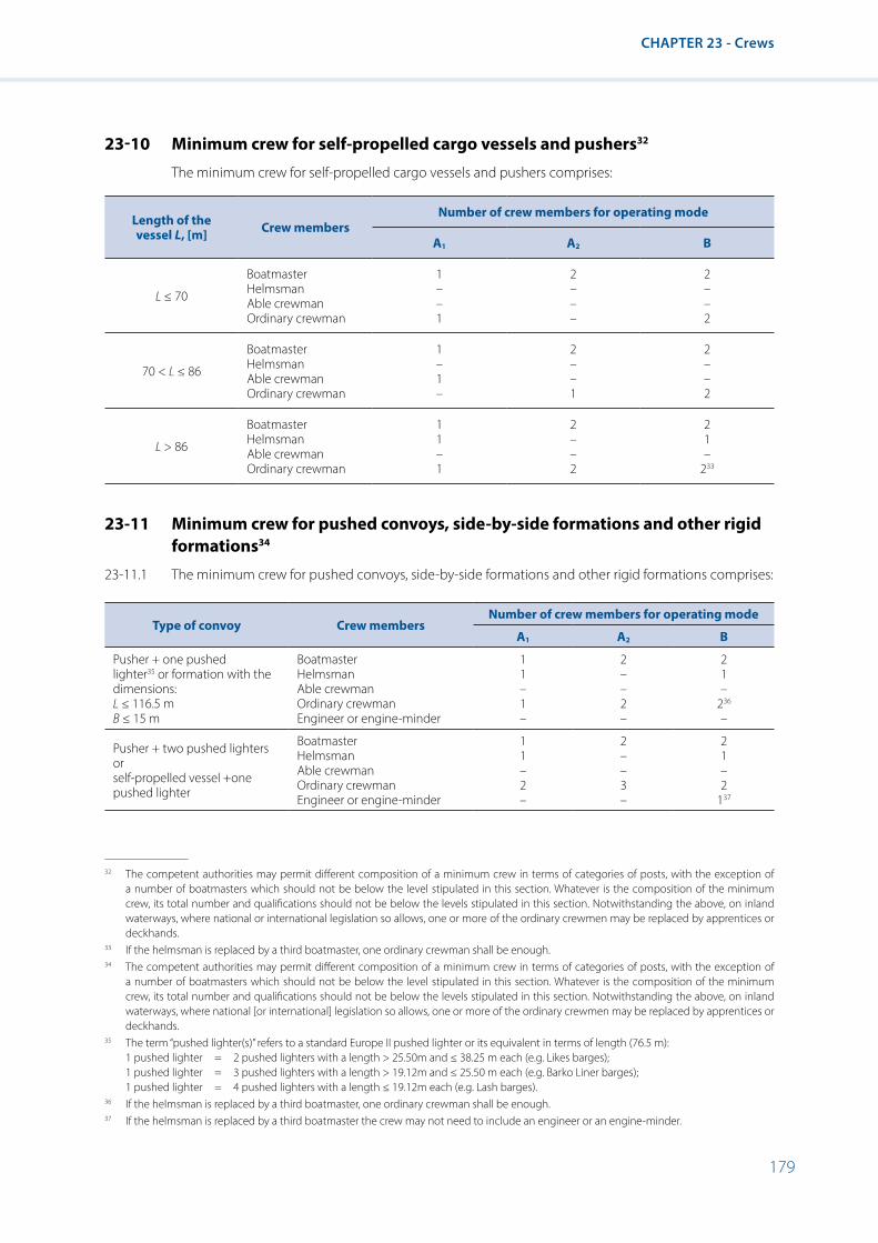
179
CHAPTER 23 - Crews
23-10 Minimum crew for self-propelled cargo vessels and pushers32
The minimum crew for self-propelled cargo vessels and pushers comprises:
Length of the vessel L, [m] Crew members
Number of crew members for operating mode
A1 A2 B
L ≤ 70
BoatmasterHelmsmanAble crewmanOrdinary crewman
1 – – 1
2 – – –
2 – – 2
70 < L ≤ 86
BoatmasterHelmsmanAble crewmanOrdinary crewman
1 – 1 –
2 – – 1
2 – – 2
L > 86
BoatmasterHelmsmanAble crewmanOrdinary crewman
1 1 – 1
2 – – 2
2 1 –
233
23-11 Minimum crew for pushed convoys, side-by-side formations and other rigid formations34
23-11.1 The minimum crew for pushed convoys, side-by-side formations and other rigid formations comprises:
Type of convoy Crew membersNumber of crew members for operating mode
A1 A2 B
Pusher + one pushed lighter35 or formation with the dimensions:L ≤ 116.5 mB ≤ 15 m
Boatmaster HelmsmanAble crewman Ordinary crewman Engineer or engine-minder
1 1 – 1 –
2 – – 2 –
2 1 –
236 –
Pusher + two pushed lighters orself-propelled vessel +one pushed lighter
Boatmaster Helmsman Able crewmanOrdinary crewmanEngineer or engine-minder
1 1 – 2 –
2 – – 3 –
2 1 – 2
137
32 The competent authorities may permit different composition of a minimum crew in terms of categories of posts, with the exception of a number of boatmasters which should not be below the level stipulated in this section. Whatever is the composition of the minimum crew, its total number and qualifications should not be below the levels stipulated in this section. Notwithstanding the above, on inland waterways, where national or international legislation so allows, one or more of the ordinary crewmen may be replaced by apprentices or deckhands.
33 If the helmsman is replaced by a third boatmaster, one ordinary crewman shall be enough.34 The competent authorities may permit different composition of a minimum crew in terms of categories of posts, with the exception of
a number of boatmasters which should not be below the level stipulated in this section. Whatever is the composition of the minimum crew, its total number and qualifications should not be below the levels stipulated in this section. Notwithstanding the above, on inland waterways, where national [or international] legislation so allows, one or more of the ordinary crewmen may be replaced by apprentices or deckhands.
35 The term “pushed lighter(s)” refers to a standard Europe II pushed lighter or its equivalent in terms of length (76.5 m): 1 pushed lighter = 2 pushed lighters with a length > 25.50m and ≤ 38.25 m each (e.g. Likes barges); 1 pushed lighter = 3 pushed lighters with a length > 19.12m and ≤ 25.50 m each (e.g. Barko Liner barges); 1 pushed lighter = 4 pushed lighters with a length ≤ 19.12m each (e.g. Lash barges).
36 If the helmsman is replaced by a third boatmaster, one ordinary crewman shall be enough.37 If the helmsman is replaced by a third boatmaster the crew may not need to include an engineer or an engine-minder.

180
Resolution No. 61 Revision 2
Type of convoy Crew membersNumber of crew members for operating mode
A1 A2 B
Pusher + three or four pushed lighters or self-propelled vessel + two or three pushed lighters
Boatmaster Helmsman Able crewmanOrdinary crewmanEngineer or engine-minder
1 1 – 2 1
2 – – 3 1
2 1 –
338
1
Pusher + more than fourpushed lighters
Boatmaster HelmsmanAble crewmanOrdinary crewman Engineer or engine-minder
1 1 – 3 1
2 – – 4 1
2 1 –
439 1
23-11.2 The competent authority may prescribe different manning requirements for convoys with a length of up to 82 m and a width of 11.45 m.
23-11.3 In the case of pushed lighters or towed barges, one ordinary crewman is included for every two pushed lighters or towed barges.
23-12 Minimum crew for passenger vessels40
23-12.1 The minimum crew for passenger vessels for day excursions comprises:
Maximum permitted number of passengers Crew members
Number of crew members for operating mode
A1 A2 B
Up to 75 persons
Boatmaster Helmsman Able crewman Ordinary crewman Engineer or engine-minder
1 - - 1 -
2 - - 1 -
2 - - 2 -
Between 76 and 250 persons
Boatmaster Helmsman Able crewman Ordinary crewman Engineer or engine-minder
1 - -
241 -
2 - - 1 1
2 - - 2 1
Between 251 and 600 persons
Boatmaster Helmsman Able crewman Ordinary crewman Engineer or engine-minder
1 - 1 - 1
2 - - 1 1
3 - - 1 1
Between 601 and 1 000 persons
Boatmaster Helmsman Able crewman Ordinary crewman Engineer or engine-minder
1 1 - 2 1
2 - - 2 1
3 - - 2 1
More than 1 000 persons
Boatmaster Helmsman Able crewman Ordinary crewman Engineer or engine-minder
2 - - 3 1
2 - - 4 1
3 - - 4 1
38 If the helmsman is replaced by a third boatmaster two ordinary crewmen shall be enough.39 If the helmsman is replaced by a third boatmaster three ordinary crewmen shall be enough.40 The competent authorities may permit different composition of a minimum crew in terms of categories of posts, with the exception of
a number of boatmasters which should not be below the level stipulated in this section. Whatever is the composition of the minimum crew, its total number and qualifications should not be below the levels stipulated in this section. Notwithstanding the above, on inland waterways, where national or international legislation so allows, one or more of the ordinary crewmen may be replaced by apprentices or deckhands.
41 Both ordinary crewmen may be replaced by one engineer or an engine-minder.

181
CHAPTER 23 - Crews
23-12.2 The minimum crew for steamboats for day excursions should be increased by one engineer in all operating modes.
23-12.3 The minimum crew for passenger cabin vessels comprises:42
Group according to the number of berths Crew members
Number of crew members for operating mode
A1 A2 B
Up to 50 berths
Boatmaster Helmsman Able crewman Ordinary crewman Engineer or engine-minder
1 – 1 – 1
2 – – 1 1
3 – – 1 1
Between 51 and 100 berths
Boatmaster Helmsman Able crewman Ordinary crewman Engineer or engine-minder
1 1 – 1 1
2 – – 1 1
3 – – 1 1
More than 100 berths
Boatmaster Helmsman Able crewman Ordinary crewman Engineer or engine-minder
1 1 - 2 1
2 - - 3 1
3 - - 3 1
23-13 Manning of vessels whose minimum equipment referred to in section 23-9 is incomplete
23-13.1 When the equipment of a self-propelled vessel, pusher, rigid convoy, or other rigid assembly or passenger vessel does not correspond to the standard of equipment required in paragraph 23-9.1, the minimum crew prescribed in sections 23-10, 23-11 or 23-12 shall be increased by:
(i) One ordinary crewman in operating modes A1 and A2 and
(ii) Two ordinary crewmen in operating mode B. When, however, the requirements of paragraph 23-9.1, letters (ix) and (x) only, or of one of these letters are not met, the crew shall be increased in operating mode B by one ordinary crewman instead of two.
23-13.2 In addition, when one or more of the requirements of paragraph 23-9.1, letters (i) to (iii), are not met,
(i) The ordinary crewman prescribed in 23-13.1 (i) above shall be replaced by an engine-minder in operating modes A1 and A2 and
(ii) The two ordinary crewmen prescribed in 23-13.1 (ii) above shall be replaced by two engine-minders in operating mode B.
23-14 Minimum crews for other vessels
The Administration shall determine for vessels not mentioned in sections 23-10 to 23-12 but covered by the present recommendations in accordance with section 23-1 above (e.g. tugs, towed barges, floating equipment, high-speed vessels), according to their dimensions, form of construction, equipment and intended use, what crews shall be on board during navigation.
42 The competent authorities may permit different composition of a minimum crew in terms of categories of posts, with the exception of a number of boatmasters which should not be below the level stipulated in this section. Whatever is the composition of the minimum crew, its total number and qualifications should not be below the levels stipulated in this section. Notwithstanding the above, on inland waterways, where national or international legislation so allows, one or more of the ordinary crewmen may be replaced by apprentices or deckhands.

182
Resolution No. 61 Revision 2
CHAPTER 24 - Transitional and Final Provisions
(Left void)

183
APPENDIX 1 - List of European Inland Waterways Divided Geographically into Zones 1, 2 and 3 (Paragraph 1-1.5 of the Recommendations)
APPENDIX 1 - List of European Inland Waterways Divided Geographically into Zones 1, 2 and 3 (Paragraph 1-1.5 of the Recommendations)
CHAPTER I - Zone 1
Germany
Ems, from a line linking the former Greetsiel lighthouse and the western pier of the port entrance at Eemshaven as far as latitude 53°30’N and longitude 6°45’E, i.e. slightly seawards of the lightering area for dry-cargo carriers in the Alte Ems. In the case of vessels whose home port is elsewhere, account is to be taken of article 32 of the Ems-Dollart Treaty of 8 April 1960 (BGBl. 1963 II, p. 602).
Poland
Pomorska Bay, to the south of the line linking the headland of Nord Perd on the Rügen Island and the Niechorze lighthouse.
Gdansk Bay, to the south of the line running from the Hel lighthouse to the entrance buoy to the port of Baltijsk.
Russian FederationVygozero.
Volgogradskoe Reservoir, from Uvek bridge to the dam at the Volgograd hydroelectric power station.
Votkinskoe Reservoir, from the Chastye wharf to the dam at the Votkinsk hydroelectric power station.
Kamskoe Reservoir, from Berezniki to the dam at the Kama hydroelectric power station.
Kuybyshevskoe Reservoir, along the Volga river, from the town of Kamskoe Ustye to the dam at the Kuybyshev hydroelectric power station; along the Kama river from Chistopol to Kamskoe Ustye.
Rybinskoe Reservoir, with the exception of the northern section from Cherepovets to Vichelovo.
Tsimlyanskoe Reservoir, from Pyatiizbyan roadsteads to the dam at Tsimlyansk hydroelectric power station.
Volgokaspijskiy Kanal, from buoy 217 (146.0 km) to the Astrakhan lighthouse.
Don, from Azov to the port of Taganrog.
Nizhne-Kamskoe Reservoir, from the town of Ust-Belsk (1,766 km) to the dam at the Lower Kama hydroelectric power station;
Mezen, from the mouth of the Bolshaya Chetsa River to the Mezen entrance buoy.
Pechora, from the Alekseevsky Island to the line between the Cape of Bolvansky Nos – northern extremity of the Lovetsky Island.
Northern Dvina – along the Maymaksan branch from the village of Lapominka to the southern extremity of the Mudiug Island, along the Murmansk branch to the Kumbysh Island.
Ukraine
Dniprobuzkiy Lyman, up to the Port of Ochakiv.
Pivdenny Buh, downstream of Mykolaiv sea port.
Kakhovske reservoir, from the dam of Kakhovska Hydro-electric Plant to Bilenka wharf (180 km).
Kremenchutske Reservoir, from the dam of Kremenchutska Hydro-electric Plant to the Topylivka village (70 km).
184
Resolution No. 61 Revision 2
United Kingdom of Great Britain and Northern Ireland
1. Inland waterways of Scotland
Blue Mull Sound, between Gutcher and Belmont.
Yell Sound, between Tofts Voe and Ulsta.
Sullom Voe, within a line from the north-east point of Gluss Island to the northern point of Calback Ness.
Dales Voe, in winter: within a line from the north point of Kebister Ness to the Coast of Breiwick at longitude 1°10.8’W; in summer: as for Lerwick.
Lerwick, in winter: within the area bounded to the northward by a line from Scottle Holm to Scarfi Taing on Bressay and to the southward by a line from Twageos Point Lighthouse to Whalpa Taing on Bressay. In summer: within the area bounded to the northward by a line from Brim Ness to the north east corner of Inner Score and to the southward by a line from the south end of Ness of Sound to Kirkabisterness.
Kirkwall, between Kirkwall and Rousay not east of a line between Point of Graand (Egilsay) and Galt Ness (Shapinsay) or between Head of Work (Mainland) through Helliar Holm light to the shore of Shapinsay; not north west of the south east tip of Eynhallow Island, not to seaward and a line between the shore on Rousay at 59°10.5N 002°57.1W and the shore on Egilsay at 59°10.0N 002°56.4W.
Stromness, to Scapa but not outside Scapa Flow.
Scapa Flow, within an area bounded by lines drawn from Point of Cletts on the island of Hoy to Thomson’s Hill triangulation point on the island of Fara and thence to Gibraltar Pier on the island of Flotta; from St Vincent Pier on the island of Flotta to the westernmost point of Calf of Flotta; from the easternmost point of the Calf of Flotta to Needle Point on the island of South Ronaldsay and from the Ness on Mainland to Point of Oxan lighthouse on the island of Graemsay and thence to Bu Point on the island of Hoy; and seaward of zone 2 waters.
Balnakiel Bay, between Eilean Dubh and A’Chleit.
Cromarty Firth, within a line from North Sutor to Nairn Breakwater and seaward of zone 2 waters.
Inverness, within a line from North Sutor to Nairn Breakwater and seaward of zone 2 waters.
River Tay – Dundee, within a line from Broughty Castle to Tayport and seaward of zone 2 waters.
Firth of Forth and River Forth, within a line from Kirkcaldy to River Portobello and seaward of zone 2 waters.
Solway Firth, within a line from Southerness Point to Silloth.
Loch Ryan, within a line from Finnart’s Point to Milleur Point and seaward of zone 2 waters.
The Clyde, Outer limit: a line from Skipness to a position one mile south of Garroch Head thence to Farland Head; Inner limit in winter: a line from Cloch Lighthouse to Dunoon Pier; Inner limit in summer: a line from Bogany Point, Isle of Bute to Skelmorlie Castle and a line from Ardlamont Point to the southern extremity of Ettrick Bay inside the Kyles of Bute. Note: The above inner summer limit is extended between 5 June and 5 September (both dates inclusive) by a line from a point two miles off the Ayrshire coast at Skelmorlie Castle to Tomont End, Cumbrae, and a line from Portachur Point, Cumbrae to Inner Brigurd Point, Ayrshire.
Oban, within an area bounded on the north by a line from Dunollie Point Light to Ard na Chruidh and to the south by a line from Rudha Seanach to Ard na Cuile.
Kyle of Lochalsh, through Loch Alsh to the head of Loch Duich.
Loch Gairloch, in winter: none. In summer: South of a line running east from Rubha na Moine to Eilan Horrisdale and thence to Rubha nan Eanntag.

185
APPENDIX 1 - List of European Inland Waterways Divided Geographically into Zones 1, 2 and 3 (Paragraph 1-1.5 of the Recommendations)
2. Inland waterways of Northern Ireland
Belfast Lough, in winter: none. In summer: within a line from Carrickfergus to Bangor and seaward of zone 2 waters.
Loch Neagh, at a greater distance than 2 miles from the shore.
3. Inland waterways of East coast of England
River Humber, in winter: within a line from New Holland to Paull. In summer: within a line from Cleethorpes Pier to Patrington Church and seaward of zone 2 waters.
4. Inland waterways of Wales and West coast of England
River Severn, in winter: within a line from Blacknore Point to Caldicot Pill, Porstkewett. In summer: within a line from Barry Dock Pier to Steepholm and thence to Brean Down and seaward of zone 2 waters.
River Wye, in winter: within a line from Blacknore Point to Caldicot Pill, Portskewett. In summer: within a line from Barry Dock Pier to Steepholm and thence to Brean Down and seaward of zone 2 waters.
Newport, in winter: none. In summer: within a line from Barry Dock Pier to Steepholm and thence to Brean Down and seaward of zone 2 waters.
Cardiff, in winter: none. In summer: within a line from Barry Dock Pier to Steepholm and thence to Brean Down and seaward of zone 2 waters.
Barry, in winter: None. In summer within a line from Barry Dock Pier to Steepholm and thence to Brean Down and seaward of zone 2 waters.
Swansea, within a line joining the seaward ends of the breakwaters.
Menai Straits, within the Menai Straits from a line joining Llanddwyn Island Light to Dinas Dinlleu and lines joining the south end of Puffin Island to Trwyn DuPoint and Llanfairfechan Railway Station, and seaward of zone 2 waters.
River Dee, in winter: within a line from Hilbre Point to Point of Air. In summer: within a line from Formby Point to Point of Air and seaward of zone 2 waters.
River Mersey, in winter: None. In summer: within a line from Formby Point to Point of Air and seaward of zone 2 waters.
Preston and Southport, within a line from Southport to Blackpool inside the banks and seaward of zone 2 waters.
Fleetwood, in winter: None. In summer: within a line from Rossal Point to Humphrey Head and seaward of zone 2 waters.
River Lune, in winter: None. In summer: within a line from Rossal Point to Humphrey Head and seaward of zone 2 waters.
Heysham, in winter: None. In summer: within a line from Rossal Point to Humphrey Head.
Morecambe, in winter: None. In the summer: from within a line from Rossal Point to Humphrey Head.
Workington, within a line from Southerness Point to Silloth and seaward of zone 2 waters.
5. Inland waterways of South of England
River Colne, Colchester, in winter: within a line from Colne Point to Whitstable. In summer: within a line from Clacton Pier to Reculvers.
River Blackwater, in winter: within a line from Colne Point to Whitstable. In summer: within a line from Clacton Pier to Reculvers and seaward of zone 2 waters.
River Crouch and River Roach, in winter: within a line from Colne Point to Whitstable. In summer: within a line from Clacton Pier to Reculvers and seaward of zone 2 waters.

186
Resolution No. 61 Revision 2
River Thames and its tributaries, in winter: within a line from Colne Point to Whitstable. In summer: within a line from Clacton Pier to Reculvers and seaward of zone 2 waters.
River Medway and the Swale, in winter: within a line from Colne Point to Whitstable. In summer: within a line from Clacton Pier to Reculvers and seaward of zone 2 waters.
Chichester, inside the Isle of Wight within an area bounded by lines drawn between the church spire, West Wittering, to Trinity Church, Bembridge, to the eastward, and the Needles and Hurst Point to the westward and seaward of zone 2 waters.
Langstone Harbour, inside the Isle of Wight within an area bounded by lines drawn between the church spire, West Wittering, to Trinity Church, Bembridge, to the eastward, and the Needles and Hurst Point to the westward and seaward of zone 2 waters.
Portsmouth, inside the Isle of Wight within an area bounded by lines drawn between the church spire, West Wittering, to Trinity Church, Bembridge, to the eastward, and the Needles and Hurst Point to the westward and seaward of zone 2 waters.
Bembridge, Isle of Wight, inside the Isle of Wight within an area bounded by lines drawn between the church spire, West Wittering, to Trinity Church, Bembridge, to the eastward, and the Needles and Hurst Point to the westward and seaward of zone 2 waters.
Cowes, Isle of Wight, inside the Isle of Wight within an area bounded by lines drawn between the church spire, West Wittering, to Trinity Church, Bembridge, to the eastward, and the Needles and Hurst Point to the westward and seaward of zone 2 waters.
Southampton, inside the Isle of Wight within an area bounded by lines drawn between the church spire, West Wittering, to Trinity Church, Bembridge, to the eastward, and the Needles and Hurst Point to the westward and seaward of zone 2 waters.
Beaulieu River, inside the Isle of Wight within an area bounded by lines drawn between the church spire, West Wittering, to Trinity Church, Bembridge, to the eastward, and the Needles and Hurst Point to the westward and seaward of zone 2 waters.
Keyhaven Lake, inside the Isle of Wight within an area bounded by lines drawn between the church spire, West Wittering, to Trinity Church, Bembridge, to the eastward, and the Needles and Hurst Point to the westward and seaward of zone 2 waters.
Weymouth, within Portland Harbour and between the River Wey and Portland Harbour.
Plymouth, within a line from Cawsand to Breakwater to Staddon and seaward of zone 2 waters.
Falmouth, in winter: within a line from St. Anthony Head to Rosemullion. In summer: within a line from St. Anthony Head to Nare Point and seaward of zone 2 waters.
River Camel, within a line from Stepper Point to Trebetherick Point and seaward of zone 2 waters.
Bridgewater, within the bar and seaward of zone 2 waters.
River Avon (Avon), in winter: within a line from Blacknore Point to Caldicot Pill, Portskewett. In summer: within a line from Barry Pier to Steepholm and thence to Brean Down and seaward of zone 2 waters.

187
APPENDIX 1 - List of European Inland Waterways Divided Geographically into Zones 1, 2 and 3 (Paragraph 1-1.5 of the Recommendations)
CHAPTER II - Zone 2
Czech Republic
Dam Lake Lipno.
France
Gironde, from kilometre point (KP) 402 to the transversal limit of the sea defined by the line joining the Pointe de Grave to the Pointe de Suzac.
Loire, from Cordemais (KP 25) to the transversal limit of the sea defined by the line joining the Pointe de Mindin to the Pointe de Penhoët.
Rhône, downstream from Trinquetaille bridge at Arles and beyond towards Marseilles.
Seine, from the start of the Tancarville Canal to the transversal limit of the sea defined by the line from Cape Hode, on the right bank, to the point, on the left bank, where the planned dyke meets the coast below Berville.
Vilaine, from the Arzal Dam to the transversal limit of the sea defined by the line joining the Pointe du Scal to the Pointe du Moustoir.
Lake Geneva.
Germany
Ems, from a line across the river Ems near the entrance to Papenburg harbour between Diemen the former pumping station and the opening of the dyke at Halte as far as a line linking the former Greetsiel lighthouse and the western pier of the port entrance at Eemshaven.
Jade, inside a line linking the former Schillighörn cross light and Langwarden church tower.
Weser, from the north-western edge of the Bremen railway bridge as far as a line linking Langwarden and Cappel church towers with the side branches: Westergate, Rekumer Loch, Rechter Nebenarm and Schweiburg.
Elbe, Bütztflether Süderelbe (from km 0.69 till the mouth in the Elbe), Ruthenstrom (from km 3.75 till the mouth in the Elbe), Wischhafener Süderelbe (from km 8.03 till the mouth in the Elbe) from the lower limit of the port of Hamburg to a line linking the Döse beacon and the north-western point of the Friedrichskoog dyke (Dieksand) with the Nebenelben as well as the tributaries: Este, Lühe, Schwinge, Oste, Pinnau, Krückau and Stör (in each case from the barrage to the mouth).
Meldorfer Bucht, inside a line linking the western edge of Friedrichskoog dyke (Dieksand) and Büsum west pier head.
Eider, from the mouth of the Gieselau Canal (km 22.64) to the line between the middle of the fortress (Tränke) and the churchtower of Vollerwiek.
Gieslau Canal, from the mouth in the Eider till the the mouth in the Nord-Ostsee Canal.
Flensburger Förde, inside a line linking Kegnäs lighthouse and Birknack and North from the German-Danish border in the Flensburger Förde.
Schlei, inside a line linking the Schleimünde pier heads.
Eckernförder Bucht, inside a line linking Boknis-Eck to the north-eastern point of the mainland near Dänisch Nienhof.
Kieler Förde, inside a line linking Bülk lighthouse at the Laboe naval memorial.

188
Resolution No. 61 Revision 2
Nord-Ostsee-Kanal (Kiel Canal including Audorfer See and Schirnauer See), from the line linking the Brunsbüttel pier heads to a line linking the entrance lights of Kiel-Holtenau including Obereidersee with Enge, Audorfer See, Bergstedter See, Schirnauer See, Flemhuder See and Achterwehrer Schiffahrtskanal.
Trave, from the north-western edge of the railway lift bridge in Lübeck with the Pötenitzer Wiek, and the Dassower See as far as a line linking the southern inner and northern outer pier heads at Travemünde.
Leda, from the entrance to the outer harbour of the Leer sea lock to the mouth in the Eems.
Hunte, from Oldenburg harbour and from 140 m downstream of the Amalienbrücke in Oldenburg to the mouth in the Weser.
Lesum, from the confluence of the Hamme and Wümme (km 0,00) to the mouth in the Weser.
Este, from the tail water of Buxtehude lock (km 0,25) to the mouth in the Elbe.
Lühe, from the tail water of the Au-Mühle in Horneburg (km 0,00) to the mouth in the Elbe.
Schwinge, from the north edge of the Salztor lock in Stade to the mouth in the Elbe.
Freiburger Hafenpriel, from the eastern edge of the sluice in Freiburg/Elbe as far as the mouth.
Oste, from 210 m above the middleline of the traffic bridge over the Oste barrage (km 69,360) to the mouth in the Elbe.
Pinnau, from the south-western edge of the railway bridge in Pinneberg to the mouth in the Elbe.
Krückau, from the south-western edge of the bridge leading to/from the Wedenkamp in Elmshorn to the mouth in the Elbe.
Stör, from the Rensing tide gauge to the mouth in the Elbe.
Freiburger Hafenpriel, from the eastern edge of the sluice in Freiburg an der Elbe as far as the mouth in the Elbe.
Wismarbucht, Kirchsee, Breitling, Salzhaff and Wismar port area, limited seawards by a line: Hohen Wieschendorf Huk and Timmendorf light as well as Gollwitz light on the Island of Poel and the southern point of Wustrow Peninsula.
Warnow, including Breitling and side branches, downstream of the Mühlendamm from the northern edge of the Geinitzbrücke in Rostock towards the sea as far as a line linking the northern points of the western and eastern piers in Warnemünde.
Waters between the mainland and the Darss and Zingst peninsulas as well as the Hiddensee and Rügen islands (including Stralsund port area), limited seawards between:
• The Zingst peninsula and the island of Bock by the parallel of latitude 54°26’42’’N;
• The islands of Bock and Hiddensee by a line linking the northern point of the island of Bock and the southern point of the island of Hiddensee;
• The island of Hiddensee and the island of Rügen (Bug) by a line linking the south-eastern point of Neubessin to Buger Haken.
Kleine Jasmunder Bodden.
Greifswalder Bodden and Greifswald port area including the river Ryck, Bodden seawards as far as a line from the eastern point Thiessower Haken (Südperd) to the eastern point of the island of Ruden and continuing to the northern point of the island of Usedom (54°10’37’’N, 13°47’51’’E).
Ryck, east from the Steinbecker bridge in Greifswald to the linking line over the heads of the jetties.

189
APPENDIX 1 - List of European Inland Waterways Divided Geographically into Zones 1, 2 and 3 (Paragraph 1-1.5 of the Recommendations)
Waters enclosed by the mainland and the island of Usedom (Peenestrom including Wolgast port area, Achterwasser, and the Oder Haff ), limited in the east by the border between the Federal Republic of Germany and the Republic of Poland in the Stettiner Haff.
Uecker, from the south-west edge of the traffic bridge in the Uekermünde to the linking line over he heads of the jetties.
Hungary
Lake Balaton
Lithuania
Curonian Lagoon, from the mouth of river Atmata to Klaipeda.
Netherlands
Dollard.
Eems.
Waddenzee, including the links with the North Sea.
IJsselmeer, including the Markermeer and the IJmeer but excluding the Gouwzee.
Nieuwe Waterweg and Scheur.
Hollands Diep.
Harringvliet and Vuile Gat, including the waterways between Goeree-Overflakkee on the one hand and Voorne-Putten and Hoekse Waard on the other.
Hellegat.
Volkerak.
Krammer.
Grevelingenmeer and Brouwershavense Gat, including all the waterways between Schouwen-Duiveland and Goeree-Overflakkee.
Keten, Mastgat, Krabbenkreek, Zijpe Eastern Scheldt and Roompot, including the waterways between Walcheren, Noord-Beveland and Zuid-Beveland on the one hand and Schouwen-Duiveland and Tholen on the other hand, excluding the Scheldt-Rhine Canal.
Scheldt and Western Scheldt and its mouth on the sea, including the waterways between Zeeland Flanders on the one hand and Walcheren and Zuid-Beveland on the other, excluding the Scheldt-Rhine Canal.
Breediep, Beerkanaal and its connected harbours.
Kanaal west from the Benelux harbour.
Poland
Lagoon of Szczecin.
Lagoon of Kamień.
Lagoon of Wisła.
Bay of Puck.
Włocławski Reservoir.

190
Resolution No. 61 Revision 2
Lake Śniardwy.
Lake Niegocin.
Lake Mamry.
Republic of Moldova
Dubossarskoe Reservoir.
Koshteshtskoe Reservoir.
Russian Federation
Beloe Lake.
Gorkovskoe Reservoir.
Ivankovskoe Reservoir.
Rybinskoe Reservoir, from Cherepovets to Vichelovo.
Saratovskoe Reservoir, from Syzran bridge to the dam at the Saratov hydroelectric power station.
Uglicheskoe Reservoir.
Sheksninskoe Reservoir.
Don, from Rostov-na-Donu to Azov.
Svir.
Volgo-Donskoj Kanal, from Volgograd to Pyatiizbyanskije roadsteads.
Kanal im. Moskvi, from the Bolshaya Volga wharf to lock No. 7.
Volgo-Kaspijskiy Kanal, from the town of Krasnye Barrikady (0.0 km) to buoy 217 (146.0 km).
Chudskoye Lake.
Ilmen Lake.
Kubenskoye Lake.
Pskovskoye Lake.
Veselovskoe Reservoir.
Krasnodarskoe Reservoir.
Cheboksarskoe Reservoir.
Belaya, from Yamalinsky Yar (1,786 km) to the mouth.
Volga, from the city of Tver to the town of Koprino (including Ivankovskoe and Uglichskoe reservoirs), from the dam at the Rybinsk hydro-electric power station to the Elyat mouth, from the dam at the Gorkovskaya hydro-electric power station to the Sura mouth, from the dam at the Cheboksary hydro-electric power station to the village of Kamskoe Ustye, from the dam at the Kuibyshevskaya hydro-electric power station to Syzran bridge, from the dam at the Saratov hydro-electric power station to Uvek bridge, from the dam at the Volgograd hydro-electric power station to the town of Krasnye Barrikady.
Kama, from the dam at the Kama hydro-electric power station to the Chastye wharf, from the dam at the Votkinsk hydro-electric power station to the town of Ust-Belsk (1,766 km), from the dam at the Lower Kama hydro-electric power station to Tchistopol.
Mezen, from the city of Mezen to the Bolshaya Chetsa mouth.

191
APPENDIX 1 - List of European Inland Waterways Divided Geographically into Zones 1, 2 and 3 (Paragraph 1-1.5 of the Recommendations)
Neva, from the source to the border of the inland waterways: along the Bolshaya Neva, Lieutenant Schmidt bridge; along the Malaya Neva – the alignment of the 1st Line of the Vasilyev island; along the Bolshaya Nevka – the alignment of spit of the Elagin island; along the Srednaya Nevka, the upper cape of the mouth of the Chukhonka river (the entrance to the rowing canal); along the Malaya Nevka, Petrovsky bridge.
Northern Dvina, from the Pinega mouth to the Uyma mouth; along the Maymaksan branch from the Uyma mouth to the village of Lapominka; along the Nikolskiy branch and channels between the isles of Yagra, Uglomin and Nikolsky to south-west extremity of the isle of Yagra.
White Sea access canal to the entrance buoy.
Gulfs of Veslinsk and Kaliningrad including the sea port of Kaliningrad and the canal to the line between the ends of the south and north moles of the port of Baltiysk.
Volga-Baltic Canal, from the Onega Lake to the dam at the Sheksna hydroelectric power station including the Sizmin flooding.
Gulf of Kurshsky to the line between the ends of the south and north moles of the entrance gate to the port of Klaipeda.
Nevskaya Guba, from the border of inland waterways to the dam along the line between Gorskaya, Kronshtadt, Oranienbaum;
Petchora, from the village of Ust-Tzilma to the city of Naryan-Mar.
Ukraine
Dnipro, downstream of the Port of Kyiv (with the exception of areas belonging to zone 1) and the section from the wharf Teremtsy to the dam of Kyiv Hydro-electric Plant.
Prypiat, downstream of Vydoumka wharf.
Pivdenny Buh, from Ternovate village to Mykolaiv sea port.
Dnistrovsky Lyman.
Dnistrovske Reservoir, from the dam to Dnistrovka village (60 km).
Kakhovske Reservoir, upstream of the Bilenka wharf (180 km).
Dniprovske Reservoir.
Kremenchutske Reservoir, upstream of Topylivka village (70 km).
Kamianske Reservoir.
Kanivske Reservoir, from the dam of Kanivska Hydro-electric Plant to Novo-Ukrainka wharf.
Kyivske Reservoir, from the dam of Kyivska Hydro-electric Plant to Teremtsy wharf on the Dnipro and to Vydumka wharf on the Pripyat.
Pechenezke Reservoir.
Krasnooskolske Reservoir.
Burshtynske Reservoir.
Svitiaz Lake.

192
Resolution No. 61 Revision 2
United Kingdom of Great Britain and Northern Ireland
1. Inland waterways of Scotland
Scapa Flow, within an area bounded by lines drawn from Wharth on the island of Flotta to the Martello Tower on South Walls, and from Point Cletts on the island of Hoy to Thomson’s Hill triangulation point on the island of Fara and thence to Gibraltar Pier on the island of Flotta.
Kyle of Durness, south of Eilean Dubh.
Cromarty Firth, within a line between North Sutor and South Sutor.
Inverness, within a line from Fort George to Chanonry Point.
Findhorn Bay, within the spit.
Aberdeen, within a line from South Jetty to Abercromby Jetty.
Montrose Basin, to the west of a line running north-south across the harbour entrance at Scurdie Ness Lighthouse.
River Tay – Dundee, within a line from the tidal basin (fish dock), Dundee to Craig Head, East Newport.
Firth of Forth and River Forth, within the Firth of Forth but not east of the Forth railway bridge.
Dumfries, within a line from Airds Point to Scar Point.
Loch Ryan, within a line from Cairn Point to Kircolm Point.
Ayr Harbour, inside the Bar.
The Clyde, above zone 1 waters.
Kyles of Bute, between Colintraive and Rhubodach.
Campbeltown Harbour, within a line from Macringan’s Point to Ottercharach Point.
Loch Etive, within Loch Etive above the Falls of Lora.
Loch Leven, above the bridge at Ballachulish.
Loch Linnhe, North of Corran Point light.
Loch Eil, the whole loch.
Caledonian Canal, Lochs Lochy, Oich and Ness.
Kyle of Lochalsh, within Kyle Akin not westward of Eilean Ban Light or eastward of Eileanan Dubha.
Loch Carron, between Stromemore and Strome Ferry.
Loch Broom, Ullapool, within a line from Ullapool Point Light to Aultnaharrie.
Kylesku, across Loch Cairnbawn in the area between the easternmost point of Garbh Eilean and the westernmost point of Eilean na Rainich.
Stornoway Harbour, within a line from Arnish Point to Sandwick Bay Lighthouse, north-west side.
The Sound of Scalpay, not east of Berry Cove (Scalpay) and not west of Croc a Loin (Harris).
North Harbour, Scalpay and Tarbert Harbour, within one mile from the shore of the Island of Harris.
Loch Awe, the whole loch.
Loch Katrine, the whole loch
Loch Lomond, the whole loch.
Loch Tay, the whole loch
Loch Loyal, the whole loch.

193
APPENDIX 1 - List of European Inland Waterways Divided Geographically into Zones 1, 2 and 3 (Paragraph 1-1.5 of the Recommendations)
Loch Hope, the whole loch.
Loch Shin, the whole loch.
Loch Assynt, the whole loch.
Loch Glascarnoch, the whole loch.
Loch Fannich, the whole loch.
Loch Maree, the whole loch.
Loch Gairloch, the whole loch.
Loch Monar, the whole loch.
Loch Mullardach, the whole loch.
Loch Cluanie, the whole loch.
Loch Loyne, the whole loch.
Loch Garry, the whole loch.
Loch Quoich, the whole loch.
Loch Arkaig, the whole loch.
Loch Morar, the whole loch.
Loch Shiel, the whole loch.
Loch Earn, the whole loch.
Loch Rannoch, the whole loch.
Loch Tummel, the whole loch.
Loch Ericht, the whole loch.
Loch Fionn, the whole loch.
Loch Glass, the whole loch.
Loch Rimsdale/nan Clar, the whole loch.
2. Inland waterways of Northern Ireland
Strangford Lough, within a line from Cloghy Point to Dogtail Point.
Belfast Lough, within a line from Holywood to Macedon Point.
Larne, within a line from Larne Pier to the ferry pier on Island Magee.
River Bann, from the seaward ends of the breakwaters to Toome Bridge.
Lough Erne, upper and Lower Lough Erne.
Lough Neagh, within two miles of the shore.
3. Inland waterways of East Coast of England
Berwick, within the breakwaters.
Warkworth, within the breakwaters.
Blyth, within the Outer Pier Heads.
River Tyne, Dunston Staithes to Tyne Pier Heads.
River Wear, Fatfield to Sunderland Pier Heads.
194
Resolution No. 61 Revision 2
Seaham, within the breakwaters.
Hartlepool, within a line from Middleton Jetty to Old Pier Head. Within a line joining North Pier Head to South Pier Head.
River Tees, within a line extending due west from Government Jetty to Tees Barrage.
Whitby, within Whitby Pier Heads.
River Humber, within a line from North Ferriby to South Ferriby.
Grimsby Dock, within a line from the West Pier of the Tidal Basin to the East Pier of the Fish Docks, North Quay.
Boston, inside the New Cut.
Dutch River, the whole Canal.
River Hull, Beverley Beck to River Humber.
Kielder Water, the whole Lake.
River Ouse, below Naburn Lock.
River Trent, below Cromwell Lock.
River Wharfe, from the junction with River Ouse to Tadcaster Bridge.
Scarborough, within Scarborough Pier Heads.
4. Inland waterways of Wales and West coast of England
River Severn, north of a line running due west from Sharpness Point (51°43.4’N) to Llanthony and Maisemore Weirs and seaward of zone 3 waters.
River Wye, at Chepstow, north of latitude (51°38.0’N) to Monmouth.
Newport, north of the overhead power cables crossing at Fifoots Points.
Cardiff, within a line from South Jetty to Penarth Head and the enclosed waters to the west of Cardiff Bay Barrage.
Barry, within a line joining the seaward ends of the breakwaters.
Port Talbot, within a line joining the seaward ends of the breakwaters on the River Afran outside enclosed docks.
Neath, within a line running due North from the seaward end of Baglan Bay Tanker Jetty (51°37.2’N, 3°50.5’W).
Llanelli and Burry Port, within an area bounded by a line drawn from Burry Port Western Pier to Whiteford Point.
Milford Haven, within a line from South Hook Point to Thorn Point.
Fishguard, within a line joining the seaward ends of the north and east breakwaters.
Cardigan, within the Narrows at Pen-Yr-Ergyd.
Aberystwyth, within the seaward ends of the breakwaters.
Aberdyfi, within a line from Aberdyfi Railway Station to Twyni Bach Beacon.
Barmouth, within a line from Barmouth Railway Station to Penrhyn Point.
Portmadoc, within a line from Harlech Point to Graig Ddu.
Holyhead, within an area bounded by the main breakwater and a line drawn from the head of the breakwater to Brynglas Point, Towyn Bay.
Menai Straits, within the Menai Straits between a line joining Aber Menai Point to Belan Point and a line joining Beaumaris Pier to Pen-y-Coed Point.

195
APPENDIX 1 - List of European Inland Waterways Divided Geographically into Zones 1, 2 and 3 (Paragraph 1-1.5 of the Recommendations)
Conway, within a line from Mussel Hill to Tremlyd Point.
Llandudno, within the breakwater.
Rhyl, within the breakwater.
River Dee, above Connah’s Quay to Barrelwell Hill water extraction point.
River Mersey, within a line between the Rock Lighthouse and the North West Seaforth Dock but excluding other docks.
Preston and Southport, within a line from Lytham to Southport and within Preston Docks.
Fleetwood, within a line from Low Light to Knott.
River Lune, within a line from Sunderland Point to Chapel Hill up to and including Glasson Dock.
Barrow, within a line joining Haws Point, Isle of Walney to Roa Island Slipway.
Whitehaven, within the breakwater.
Workington, within the breakwater.
Maryport, within the breakwater.
Carlisle, within a line joining Point Carlisle to Torduff.
Coniston Water, the whole Lake.
Derwentwater, the whole Lake.
Ullswater, the whole Lake.
Windermere, the whole Lake.
5. Inland waterways of South of England
Blakeney and Morston Harbour and approaches, to the east of a line running south from Blakeney Point to the entrance of the Stiffkey River.
River Orwell and River Stour, river Orwell within a line from Blackmanshead breakwater to Landguard Point and seaward of zone 3 waters.
River Blackwater, all waterways within a line from the south-western extremity of Mersea Island to Sales Point.
River Crouch and River Roach, river Crouch within a line from Holliwell Point to Foulness Point, including the River Roach.
River Thames and its Tributaries, river Thames above a line drawn north/south through the eastern extremity of Denton Wharf Pier, Gravesend to Teddington Lock.
River Medway and the Swale, river Medway from a line drawn from Garrison Point to the Grain Tower, to Allington Lock; and the Swale from Whitstable to the Medway.
River Stour (Kent), river Stour above the mouth to the landing at Flagstaff Reach.
Dover Harbour, within lines drawn across the east and west entrances to the Harbour.
River Rother, river Rother above the Tidal Signal Station at Camber to Scots Float Sluice and to the entrance lock on the River Brede.
River Adur and Southwick Canal, within a line drawn across Shoreham Harbour entrance to Southwick Canal Lock and to the west end of Tarmac Wharf.

196
Resolution No. 61 Revision 2
River Arun, river Arun above Littlehampton Pier to Littlehampton Marina.
River Ouse (Sussex) Newhaven, river Ouse from a line drawn across Newhaven Harbour entrance piers to the north end of North Quay.
Brighton, Brighton Marina outer harbour within a line from the southern end of West Quay to the north end of South Quay.
Chichester, within a line drawn between Eastoke point and the church spire, West Wittering and seaward of zone 3 waters.
Langstone Harbour, within a line drawn between Eastney Point and Gunner Point.
Portsmouth, within a line drawn across the harbour entrance from Port Blockhouse to the Round Tower.
Bembridge, Isle of Wight, within Brading Harbour.
Cowes, Isle of Wight, the River Medina within a line from the Breakwater Light on the east bank to the House Light on the west bank.
Southampton, within a line from Calshot Castle to Hook Beacon.
Beaulieu River, within Beaulieu River not eastward of a north/south line through Inchmery House.
Keyhaven Lake, within a line drawn due north from Hurst Point Low Light to Keyhaven Marshes.
Christchurch, the Run.
Poole, within the line of the Chain Ferry between Sandbanks and South Haven Point.
Exeter, within an east-west line from Warren Point to the Inshore Lifeboat Station opposite Checkstone Ledge.
Teignmouth, within the harbour.
River Dart, within a line from Kettle Point to Battery Point.
River Salcombe, within a line from Splat Point to Limebury Point.
Plymouth, within a line from Mount Batten Pier to Raveness Point through Drake’s Islands; the River Yealm within a line from Warren Point to Misery Point.
Fowey, inside the Harbour.
Falmouth, within a line from St. Anthony Head to Pendennis Point.
River Camel, within a line from Gun Point to Brea Hill.
Rivers Taw and Torridge, within a line bearing 200° from the lighthouse on Crow Point to the shore at Skern Point.
Bridgewater, south of a line running due East from Stert Point (51°13.0’N).
River Avon (Avon), within a line from Avonmouth Pier to Wharf Point, to Netham Dam.

197
APPENDIX 1 - List of European Inland Waterways Divided Geographically into Zones 1, 2 and 3 (Paragraph 1-1.5 of the Recommendations)
CHAPTER III - Zone 3
Austria
Danube, from the border with Germany to the border with Slovakia.
Inn, from the mouth to the Passau-Ingling Power Station.
Traun, from the mouth to km 1.80.
Enn, from the mouth to km 2.70.
March, to km 6,00.
Belarus
Dnepr, from the mouth of the Leshch river to the Lyubech wharf.
Neman, from Mosta to the frontier with Lithuania.
Pripyat, from the Stakhovo lock to the frontier with the Ukraine.
Zapadnaja Dvina, from the mouth of the Usvyacha river to V. Dvinsk.
Sozh, from Grodno to the mouth.
Berezina, from Borisov to the mouth.
Dneprovsko-Bugskiy Kanal, from Brest to the Stakhovo lock.
Mikashevicheskiy Kanal, from Mikashevichi to the Pripyat river.
Belgium
Maritime Scheldt, downstream of Antwerp open anchorage.
Bulgaria
Danube, from km 845.650 to km 374.100.
Croatia
Danube.
Darva, from km 0,00 to km 70.
Sava, from km 207 to km 586.
Czech Republic
Labe, from the lock Ústí nad Labem-Střekov to the lock Lovosice.
Dam Lakes: Baška, Brněnská (Kníničky), Horka (Stráž pod Ralskem), Hracholusky, Jesenice, Nechranice, Olešná, Orlík, Pastviny, Plumov, Rozkoš, Seč, Skalka, Slapy, Těrlicko, Žermanice.
Lake Máchovo.
Water Area Velké Žernoseky.
Ponds: Oleksovice, Svět, Velké Dářko.
Mining Gravel Lakes: Dolní Benešov, Ostrožná Nová Ves a Tovačov.

198
Resolution No. 61 Revision 2
France
Adour, from the Bec du Gave to the sea.
Aulne, from the lock at Châteaulin to the transversal limit of the sea defined by the Passage de Rosnoën.
Blavet, from Pontivy to the Pont du Bonhomme.
Calais Canal.
Charente, from the bridge at Tonnay-Charente to the transverse limit of the sea defined by the line passing through the centre of the downstream light on the left bank and through the centre of the Fort de la Pointe.
Dordogne, from the confluence with the Lidoire to the Bec d’Ambès.
Garonne, from the bridge at Castet en Dorthe to the Bec d’Ambès.
Gironde, from the Bec d’Ambès to the transversal line at KP 48.50 and passing through the downstream point of the Ile de Patiras.
Hérault, from the port of Bessan to the sea, as far as the upper limit of the tidal foreshore.
Isle, from the confluence with the Dronne to the confluence with the Dordogne.
Loire, from the confluence with the Maine to Cordemais (KP 25).
Marne from the bridge at Bonneuil (KP 169bis900) and the lock at St Maur to the confluence with the Seine.
Rhine.
Nive, from the Haïtze dam at Ustaritz to the confluence with the Adour.
Oise, from Janville lock to the confluence with the Seine.
Orb, from Sérignan to the sea, as far as the upper limit of the tidal foreshore.
Rhône, from the frontier with Switzerland to the sea, with the exception of the Petit Rhône.
Saône, from the Pont de Bourgogne bridge at ChalonsurSaône to the confluence with the Rhône.
Seine, from the lock at NogentsurSeine to the start of the Tancarville Canal.
Sèvre Niortaise, from the lock at Marans at the transverse limit of the sea opposite the guardhouse to the mouth.
Somme, from the downstream side of the Pont de la Portelette bridge at Abbeville to the viaduct of the Noyelles to Saint-Valéry-sur-Somme railway.
Vilaine, from Redon (KP 89.345) to the Arzal Dam.
Lake Amance.
Lake Annecy.
Lake Biscarosse.
Lake Bourget.
Lake Carcans.
Lake Cazaux.
Lake Der-Chantecoq.
Lake Guerlédan.
Lake Hourtin.
Lake Lacanau.
Lake Orient.

199
APPENDIX 1 - List of European Inland Waterways Divided Geographically into Zones 1, 2 and 3 (Paragraph 1-1.5 of the Recommendations)
Lake Pareloup.
Lake Parentis.
Lake Sanguinet.
Lake Serre-Ponçon.
Lake Temple.
Germany
Danube, from Kelheim (2,414.72 km) to the German/Austrian border at Jochenstein.
Rhine with Lampertheimer Altrhein (from km 4.75 to the Rhine), Altrhein Stockstadt-Erfelden (from km 9.80 to the Rhine), from the German/Swiss border to the German/Netherlands border.
Elbe (Norderelbe) including Süderelbe en Köhlbrand, from the mouth of the Elbe-Seitenkanal to the lower limit of the port of Hamburg.
Müritz.
Hungary
Danube, from km 1,812 to km 1,433.
Danube Moson, from km 14 to km 0.
Danube Szentendre, from km 32 to km 0.
Danube Ráckeve, from km 58 to km 0.
River Tisza, from km 685 to km 160.
River Dráva, from km 198 to km 70.
River Bodrog, from km 51 to km 0.
River Kettős-Körös, from km 23 to km 0.
River Hármas-Körös, from km 91 to km 0.
Channel Sió, from km 23 to km 0.
Lake Velence.
Lake Fertő.
Lithuania
River Nemunas (Neman), from Kaunas to the mouth.
Netherlands
Rhine.
Sneekermeer.
Koevordermeer.
Heegermeer.
Fluessen.
Slotermeer.

200
Resolution No. 61 Revision 2
Tjeukemeer.
Beulakkerwijde.
Belterwijde.
Ramsdiep.
Ketelmeer.
Zwartemeer.
Veluwemeer.
Eemmeer.
Alkmaardermeer.
Gouwzee.
Buiten IJ.
Afgesloten IJ.
Noordzeekanaal.
Port of IJmuiden.
Rotterdam port area.
Nieuwe Maas.
Noord.
Oude Maas.
Beneden Merwede.
Nieuwe Merwede.
Dordtsche Kil.
Boven Merwede.
Waal.
Bijlandsch Canal.
Boven Rijn.
Pannersdensch Canal.
Geldersche IJssel.
Neder Rijn.
Lek.
Amsterdam-Rhine Canal.
Veerse Meer.
Scheldt-Rhine Canal as far as the mouth in the Volkerak.
Amer.
Bergsche Maas.
Meuse, downstream from Venlo.
Gooimeer.

201
APPENDIX 1 - List of European Inland Waterways Divided Geographically into Zones 1, 2 and 3 (Paragraph 1-1.5 of the Recommendations)
Europoort.
Caland Canal, east of Benelux Port.
Hartel Canal.
Poland
River Biebrza, from the estuary of the Augustowski Canal to the estuary of the river Narwia.
River Brda, from the link with the Bydgoski Canal in Bydgoszcz to the estuary of the river Wisła.
River Bug, from the estuary of the river Muchawiec to the estuary of the river Narwia.
Lake Dąbie, to the frontier with internal sea waters.
The Augustowski Canal, from the link with the river Biebrza to the State border, together with the lakes located along the route of this Canal.
The Bartnicki Canal, from Lake Ruda Woda to Lake Bartężek, together with Lake Bartężek.
The Bydgoski Canal.
The Elbląski Canal, from Lake Druzno to Lake Jeziorak and Lake Szeląg Wielki, together with these lakes and the lakes on the route of the Canal, and a byway in the direction of Zalewo from Lake Jeziorak to Lake Ewingi, inclusive.
The Gliwicki Canal, together with the Canal Kędzierzyński.
The Jagielloński Canal, from the link with the river Elbląg to the river Nogat.
The Łączański Canal.
The Ślesiński Canal, with the lakes located along the route of this Canal and Lake Gopło.
The Żerański Canal.
River Martwa Wisła, from the river Wisła in Przegalina to the frontier with internal sea waters.
River Narew, from the estuary of the river Biebrza to the estuary of the river Wisła, together with Lake Zegrzyński.
River Nogat, from the river Wisła to the estuary of the Lagoon of Wisła.
River Noteć (upper), from Lake Gopło to the link with the Górnonotecki Canal and the Górnonotecki Canal, and
River Noteć (lower), from the link of the Bydgoski Canal to the estuary to River Warta.
River Nysa Łużycka, from Gubin to the estuary to River Odra.
River Odra, from the town of Racibórz to the link with River Eastern Odra which turns into River Regalica from the Klucz-Ustowo Piercing, together with that river and its side-branches to Lake Dąbie as well as a byway of River Odra from the Opatowice lock to the lock in Wrocław city.
River Western Odra, from a weir in Widuchowa (704.1 km of River Odra) to a border with internal sea waters, together with side-branches as well as the Klucz-Ustowo Piercing linking River Eastern Odra with River Western Odra.
River Parnica and the Parnicki Piercing, from River Western Odra to a border with internal sea waters.
River Pisa, from Lake Roś to the estuary of River Narew.
River Szkarpawa, from River Wisła to the estuary of the Lagoon of Wisła.
River Warta, from the Ślesińskie Lake to the estuary of River Odra.
System of Wielkie Jeziora Mazurskie, encompassing the lakes linked by the rivers and canals constituting a main route from Lake Roś (inclusive) in Pisz to the Węgorzewski Canal (including that Canal) in Węgorzewo, together with

202
Resolution No. 61 Revision 2
Lakes Seksty, Mikołajskie, Tałty, Tałtowisko, Kotek, Szymon, Szymoneckie, Jagodne, Boczne, Tajty, Kisajno, Dargin, Łabap, Kirsajty and Święcajty, together with the Giżycki Canal and the Niegociński Canal and the Piękna Góra Canal, and a byway of Lake Ryńskie (inclusive) in Ryn to Lake Nidzkie (up to 3 km, constituting a border with the “Lake Nidzkie” nature reserve), together with lakes Bełdany, Guzianka Mała and Guzianka Wielka.
River Wisła, from the estuary of River Przemsza to the link with the Łączański Canal as well as from the estuary of that Canal in Skawina to the estuary of River Wisła to the Bay of Gdańsk, excluding the Włocławski Reservoir.
Republic of Moldova
Dnestr.
Prut, from the Koshteshtskaia hydroelectric power station to the mouth.
Romania
Danube: from the Serbian – Romanian border (km 1,075) to the Black Sea via the Sulina branch.
Danube – Black Sea Canal (64.41 km length), from the junction with the Danube river, at km 299.3 of the Danube at Cernavodă (respectively km 64.41 of the Canal), to the Port of Constanta South – Agigea (km “0” of the Canal).
Poarta Albă – Midia Năvodari Canal (27.5 km length), from the junction with the Danube – Black Sea Canal at km 29.41 at Poarta Albă (respectively km 27.5 of the Canal) to the Port of Midia (km “0” of the Canal).
Russian Federation
Belomorsko-Baltijskiy Kanal.
Severnaja Dvina, from its uppermost navigable point to the mouth of the Pinega River.
Pechora, from its uppermost navigable point to Oust-Tsylma.
Volga, from its uppermost navigable point to Tver.
Kama, from the upper reaches to the city of Berezniki.
Manych, from the dam at Veselovsk reservoir to the mouth.
Mezen, from the upper reaches to the city of Mezen.
Oka (tributary of the Volga), from the upper reaches to the mouth.
Belaya, from the upper reaches to Yamalinsky Yar (1,786 km).
Don, from the upper reaches to Piatiizbiansk roadsteads and from the dam at the Tsymliansk hydroelectric power station to Rostov-on-Don.
Voronezhskoe Reservoir.
Lakes, rivers and canals other than those mentioned in this appendix.
Serbia
Danube, from the border with Hungary to the border with Bulgaria (km 1,433 to km 845.5).
Sava, from the border with Croatia to the mouth (km 207 to km 0).
Tisa, from the border with Hungary to the mouth (km 164 to km 0).
Slovakia
Danube, from Devín (km 1,880.26) to the Slovak-Hungarian border.

203
APPENDIX 1 - List of European Inland Waterways Divided Geographically into Zones 1, 2 and 3 (Paragraph 1-1.5 of the Recommendations)
Switzerland
Rhine, from Rheinsfelden to Niffer (Kembs).
Ukraine
Dnipro, upstream of Teremtsy wharf and the section from the Port of Kyiv to the dam of Kyiv Hydro-electric Plant and the Stariy Dnipro Arm (beyond the Khortytsa Lake).
Prypiat, from the mouth to the Belarus/Ukraine state border.
Desna and other tributaries of the Dnipro.
Pivdenny Buh, upstream of Ternovate village.
Dnister, upstream of Dnistrovka village.
Danube.
Ladyzhynske Reservoir.
Dnistrovske Reservoir, from Dnistrovka village (60 km from the dam) to Vylkhovtsy village (190 km from the dam).
Other inland waterways not mentioned as belonging to zones 1 and 2.
United Kingdom of Great Britain and Northern Ireland
1. Inland waterways of Scotland
Leith (Edinburgh), within the breakwaters.
Glasgow, Strathclyde Loch.
Crinan Canal, Crinan to Ardrishaig.
Caledonian Canal, the Canal sections.
2. Inland waterways of Northern Ireland
River Lagan, Lagan Weir to Stranmillis.
3. Inland waterways of East of England
River Wear (non-tidal), Old Railway Bridge, Durham to Prebends Bridge, Durham.
River Tees, upriver from Tees Barrage.
Grimsby Dock, inside of the locks.
Immingham Dock, inside of the locks.
Hull Docks, inside of the locks.
Boston Dock, inside the lock gates.
Aire and Calder Navigation, Goole Docks to Leeds; junction with Leeds and Liverpool Canal; Bank Dole Junction to Selby (River Ouse Lock); Castleford Junction to Wakefield (Falling Lock).
River Ancholme, Ferriby Sluice to Brigg.
Calder and Hebble Canal, Wakefield (Falling Lock) to Broadcut Top Lock.
River Foss, from (Blue Bridge) junction with River Ouse to Monk Bridge.
Fossdyke Canal, junction with River Trent to Brayford Pool.
Goole Dock, inside the lock gates.

204
Resolution No. 61 Revision 2
Hornsea Mere, the whole Canal.
River Hull, from Struncheon Hill Lock to Beverley Beck.
Market Weighton Canal, river Humber Lock to Sod Houses Lock.
New Junction Canal, the whole Canal.
River Ouse, from Naburn Lock to Nun Monkton.
Sheffield and South Yorkshire Canal, Keadby Lock to Tinsley Lock.
River Trent, Cromwell Lock to Shardlow.
River Witham, Boston Sluice to Brayford Poole (Lincoln).
4. Inland waterways of Wales and West of England
River Severn, above Llanthony and Maisemore Weirs.
River Wye, above Monmouth.
Cardiff, Roath Park Lake.
Port Talbot, within the enclosed docks.
Swansea, within the enclosed docks.
River Dee, above Barrelwell Hill water extraction point.
River Mersey, the docks (excluding Seaforth Dock).
River Lune, above Glasson Dock.
River Avon (Midland), Tewkesbury Lock to Evesham.
Gloucester, Gloucester City Docks Gloucester/Sharpness Canal.
Hollingworth Lake, the whole Lake.
Manchester Ship Canal, the whole Canal and Salford Docks including River Irwell.
Pickmere Lake, the whole Lake.
River Tawe, between Sea Barrage/Marina and the Morfa Athletics Stadium.
Rudyard Lake, the whole Lake.
River Weaver, below Northwich.
5. Inland waterways of South of England
River Nene, Wisbech Cut and River Nene to Dog-in-a-Doublet Lock.
River Great Ouse, Kings Lynn Cut and River Great Ouse below West Lynn Road Bridge.
Yarmouth, River Yare Estuary from a line drawn across the ends of the north and south entrance piers, including Breydon Water.
Lowestoft, Lowestoft Harbour below Mutford Lock to a line drawn across the outer harbour entrance piers.
Rivers Alde and Ore, above the entrance to the River Ore to Westrow Point.
River Deben, above the entrance of the River Deben to Felixstowe Ferry.
River Orwell and River Stour, from a line drawn from Fagbury Point to Shotley Point on the River Orwell to Ipswich Dock; and from a line drawn north/south through Erwarton Ness on the River Stour to Manningtree.
Chelmer & Blackwater, Canal Eastward of Beeleigh Lock.

205
APPENDIX 1 - List of European Inland Waterways Divided Geographically into Zones 1, 2 and 3 (Paragraph 1-1.5 of the Recommendations)
River Thames and its tributaries, River Thames above Teddington Lock to Oxford.
River Adur and Southwick Canal, River Adur above the west end of Tarmac Wharf, and within Southwick Canal.
River Arun, river Arun above Littlehampton Marina.
River Ouse (Sussex), Newhaven, River Ouse above the north end of North Quay.
Bewl Water, the whole lake.
Grafham Water, the whole lake.
Rutland Water, the whole lake.
Thorpe Park Lake, the whole lake.
Chichester, east of a line joining Cobnor Point and Chalkdock Point.
Christchurch, within Christchurch Harbour excluding the Run.
Exeter Canal, the whole canal.
River Avon (Avon), Bristol City Docks, Netham Dam to Pulteney Weir.

206
Resolution No. 61 Revision 2
APPENDIX 2 - Model Ship’s Certificate (Paragraph 2-1.2 of the Recommendations)
APPENDIX 2
MODEL SHIP’S CERTIFICATE (paragraph 2-1.2 of the recommendations)
SHIP’S CERTIFICATE
(Reserved for State emblem) NAME OF STATE
CERTIFICATE No. ____________________________________________________________________
Place, date
__________________________________________
Competent authority on inspection of vessels
______________________________________
Seal
______________________________________ (Signature)
Remarks:
The craft may be used for navigation by virtue of this certificate only while in the condition herein described. In the event of major alterations or repairs, the craft must undergo a special inspection before any new voyage. The owner of the craft, or their representative, must inform a competent authority on inspection of crafts of any change in the name or ownership of the craft, any remeasurement and any change in the registration number or home port, and send the ship’s certificate to that authority for amendment.

207
APPENDIX 2 - Model Ship’s Certificate (Paragraph 2-1.2 of the Recommendations)
Certificate No. ___________ of the _______________________ competent authority on inspection of vessels ____________________________________________________________________________________________
1. Name of craft 2. Type of craft 3. Unique European Vessel Identification Number
4. Name and domicile of owner
5. Place of registration and registration number
6. Home port
7. Year of construction 8. Name and location of shipyard
9. This certificate replaces Certificate No. issued on by the
Competent authority on inspection of vessels.
10. The above-mentioned craft, subsequent to the inspection carried out on*
on presentation of the certificate issued on*
by the recognized Classification Society
is acknowledged as fit to operate - on waterways in zone(s) (*)
on the waterways in zone(s) (*)
in … (Names of States (*))
except for:
- on the following waterways in: (Names of the State
at the maximum authorized draught with the rigging specified below.
11. The validity of this certificate expires on
* Amendment to item(s):
New text:
* This page has been replaced.
Place, date Competent authority on inspection of vessels
Seal
Signature
* Delete as appropriate
(*))

208
Resolution No. 61 Revision 2
Certificate No. ___________ of the _______________________ competent authority on inspection of vessels ____________________________________________________________________________________________
12. The certificate number (1), unique European vessel identification number (2), registration number (3) and measurement number (4) are affixed with the corresponding signs at the following locations on the craft.
1
2
3
4
13. The maximum authorized draught is indicated on each side of the craft.
- by two - - draught marks*
- by the upper measurement plates*.
Two draught scales have been applied*.
The rear measurement scales serve as draught scales: they have been supplemented for that purpose by figures indicating the draughts*.
14. Without prejudice to the restrictions* mentioned in items 15 and 52, the craft is fit to
1. push* 4. be propelled in a side-by-side formation*
1.1 in rigid formation* 5. tow*
1.2 with controlled articulation* 5.1 craft having no motive power of its own*
2. be pushed* 5.2 motorized craft*
2.1 in rigid formation* 5.3 upstream only*
2.2 at the head of a rigid formation* 6. be towed*
2.3 with controlled articulation* 6.1 as a motorized craft*
3. propel a side-by-side formation* 6.2 as a craft with no motive power of its own*
* Amendment to item(s):
New text:
* This page has been replaced.
Place, date Competent authority on inspection of vessels
Seal
Signature
* Delete as appropriate

209
APPENDIX 2 - Model Ship’s Certificate (Paragraph 2-1.2 of the Recommendations)
Certificate No. ___________ of the _______________________ competent authority on inspection of vessels ____________________________________________________________________________________________
15. Authorised formations
1. The craft is authorised to propel the following formations:
For-mation figure
Restrictions resulting from chapters 5 and 16
Max dimensions m
Navigation direction and load status Maximum wetted section in m2
Remarks
UPSTREAM DOWNSTREAM
No. length breadth loaded t empty loaded t empty upstream downstream
2. Couplings:
Type of coupling: Number of couplings per side: Number of coupling cables:
Length of each coupling cable: m
Tensile strength per longitudinal coupling:
kN
Tensile strength per coupling cable:
kN
Number of cable windings:
* Amendment to item(s): New text:
* This page has been replaced. Place, date Competent authority on inspection of vessels
Seal
Signature * Delete as appropriate
1 2 3 4 5
6 7 8 9
10 11 12
13
14 15 16 17 Other formations:
or Starboard
Key to symbols: pusher self - propelled vessel lighter

210
Resolution No. 61 Revision 2
Certificate No. ___________ of the _______________________ competent authority on inspection of vessels ____________________________________________________________________________________________
16. Measurement certificate No. of the Measurement Office dated
17a. Length overall m 18a. Breadth overall m 19. Maximum draught m
20. Freeboard cm
17b. Length L m 18b. Breadth B m
21. Deadweight/ Water displacement*
22. Number of passengers: 23. Number of passenger berths:
t/m3*
24. Number of watertight compartments
25. Number of holds 26. Type of hatch cover
27. Number of main propulsion engines
28. Total power rating of main means of propulsion
29. Number of main propellers
kW
30. Number of bow windlasses of which ____ powered 31. Number of stern windlasses of which ____ powered
32. Number of towing hooks 33. Number of towing winches _________ of which __________ powered.
34. Steering gear
Number of rudder blades on main rudder
Main rudder drive - manual* - electric / hydraulic*
- electric* - hydraulic*
Other installations: yes / no* Type:
Flanking rudder: Flanking rudder drive: - manual* - electric / hydraulic*
yes / no* - electric* - hydraulic*
Bow rudder installation - bow rudder* - Remote control - Remote activation
yes / no* - bow thrusters* yes / no* yes / no*
- other installation*
35. Bilge pumping and draining equipment
Total calculated capacity Number of power-driven bilge pumps
Pumping capacity Number of hand pumps
l/min l/min
* Amendment to item(s):
New text:
* This page has been replaced.
Place, date Competent authority on inspection of vessels
Seal
Signature
* Delete as appropriate

211
APPENDIX 2 - Model Ship’s Certificate (Paragraph 2-1.2 of the Recommendations)
Certificate No. ___________ of the _______________________ competent authority on inspection of vessels ____________________________________________________________________________________________
36. Number and position of closing devices referred to in 8B-1.5
37. Anchors
Number of bow anchors Total mass of bow anchors Number of stern anchors Total mass of stern anchors
kg kg
38. Anchor chains
Number of bow anchor chains
Length of each chain Tensile strength of each chain
m kN
Number of stern anchor chains
Length of each chain Tensile strength of each chain
m kN
39. Mooring cables
1st cable m long with a tensile strength kN
2nd cable m long with a tensile strength kN
3rd cable m long with a tensile strength kN
40. Towing cables
with a length of m and a tensile strength of kN
with a length of m and a tensile strength of kN
41. Visual and audible signals The lights, flags, balls, floats and audible warning devices used for signalling and to emit the visual and audible signals prescribed by the European Code for Inland Waterways (CEVNI) are carried on board, as are the stand-alone emergency lights prescribed by CEVNI.
* Amendment to item(s):
New text:
* This page has been replaced.
Place, date Competent authority on inspection of vessels
Seal
Signature
* Delete as appropriate

212
Resolution No. 61 Revision 2
Certificate No. ___________ of the _______________________ competent authority on inspection of vessels ____________________________________________________________________________________________
42. Other equipment heaving line Voice communi- - alternative two-way* gangway with handrail cation system - simultaneous two-way/telephone*
- internal radio-telephone link* gaff hook Radio-telephone - vessel-to-vessel service first-aid kit installation - nautical information service - vessel-port authority service pair of binoculars notice concerning rescue of persons overboard fire-resistant receptacles Cranes - in accordance with 10-4* embarkation stairway/ladder* - cranes with a useful load not exceeding 2 000 kg*
43. Fire-fighting appliances
Number of portable Fixed sprinkler system(s) None/Number*
extinguishers Other fixed fire-fighting system(s) None/Number*
Number of fire pumps Number of hydrants Number of hoses
The powered drainage pump replaces a fire pump Yes/No*
44. Life-saving equipment
Number of lifebuoys
A life-jacket for each person regularly on board
Other individual life-saving equipment on passenger vessels*
A ship’s boat with a set of oars, one mooring line and a baler*
Other collective life-saving equipment on passenger vessels*
45. Special wheelhouse arrangements for steering on radar by one person:
Approved for steering on radar by one person*
* Amendment to item(s):
New text:
* This page has been replaced.
Place, date Competent authority on inspection of vessels
Seal
Signature
* Delete as appropriate

213
APPENDIX 2 - Model Ship’s Certificate (Paragraph 2-1.2 of the Recommendations)
Certificate No. ___________ of the _______________________ competent authority on inspection of vessels ____________________________________________________________________________________________
46. The vessel is authorized for operating modes A1*, A2
*, B*.
47. Vessel equipment in accordance with 23-9 The vessel (complies)*/(doesn’t comply)* with 23-9.1
In accordance with 23-13, the minimum crew should be increased as follows*/should not be increased*:
Operating mode
A1 A2 B
Ordinary crewman
Replacement of the ordinary crewman by an engine-minder
Observations and special conditions:
48. Minimum crew in accordance with article 23-14
Operating mode
A1 A2 B
Boatmaster
Helmsman
Able crewman
Ordinary crewman
Engineer
Engine-minder
Observations and special conditions:
* Amendment to item(s):
New text:
* This page has been replaced.
Place, date Competent authority on inspection of vessels
Seal
Signature
* Delete as appropriate

214
Resolution No. 61 Revision 2
49. Extension/confirmation* of certificate validity* Periodical/special* inspection certificate
The Competent authority on inspection of vessels inspected the vessel on *.
A certificate dated from the Recognized Classification Society
was presented to the Competent authority on inspection of vessels*. Reason for the inspection/certificate*.
In view of the inspection result/certificate*, the period of validity for the certificate is maintained/extended* until . ,
(Place) (Date)
Seal Competent authority on inspection of vessels
Signature * Delete as appropriate 49. Extension/confirmation* of certificate validity* Periodical/special* inspection certificate
The Competent authority on inspection of vessels inspected the vessel on *.
A certificate dated from the Recognized Classification Society
was presented to the Copetent authority on inspection of vessels*. Reason for the inspection/ certificate*.
In view of the inspection result/certificate*, the period of validity for the certificate is maintained/extended* until . ,
(Place) (Date)
Seal Competent authority on inspection of vessels
Signature * Delete as appropriate 49. Extension/confirmation* of certificate validity* Periodical/special* inspection certificate
The Competent authority on inspection of vessels inspected the vessel on *.
A certificate dated from the recognized Classification Society
was presented to the Competent authority on inspection of vessels*. Reason for the inspection/certificate*.
In view of the inspection result/certificate*, the period of validity for the certificate is maintained/extended* until . ,
(Place) (Date)
Seal Competent authority on inspection of vessels
Signature * Delete as appropriate

215
APPENDIX 2 - Model Ship’s Certificate (Paragraph 2-1.2 of the Recommendations)
49. Extension/confirmation* of certificate validity* Periodical/special* inspection certificate
The Competent authority on inspection of vessels inspected the vessel on *.
A certificate dated from the Recognized Classification Society
was presented to the Competent authority on inspection of vessels*. Reason for the inspection/certificate*.
In view of the inspection result/certificate*, the period of validity for the certificate is maintained/extended* until . ,
(Place) (Date)
Seal Competent authority on inspection of vessels
Signature * Delete as appropriate 49. Extension/confirmation* of certificate validity* Periodical/special* inspection certificate
The Competent authority on inspection of vessels inspected the vessel on *.
A certificate dated from the Recognized Classification Society
was presented to the Copetent authority on inspection of vessels*. Reason for the inspection/certificate*.
In view of the inspection result/certificate*, the period of validity for the certificate is maintained/extended* until . ,
(Place) (Date)
Seal Competent authority on inspection of vessels
Signature * Delete as appropriate 49. Extension/confirmation* of certificate validity* Periodical/special* inspection certificate
The Competent authority on inspection of vessels inspected the vessel on *.
A certificate dated from the recognized Classification Society
was presented to the Competent authority on inspection of vessels*. Reason for the inspection/certificate*.
In view of the inspection result/certificate*, the period of validity for the certificate is maintained/extended* until . ,
(Place) (Date)
Seal Competent authority on inspection of vessels
Signature * Delete as appropriate
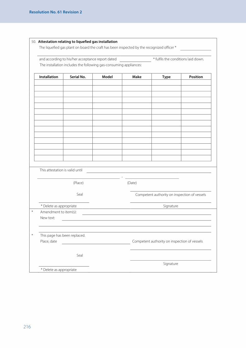
216
Resolution No. 61 Revision 2
50. Attestation relating to liquefied gas installation The liquefied gas plant on board the craft has been inspected by the recognized officer *
and according to his/her acceptance report dated * fulfils the conditions laid down.
The installation includes the following gas-consuming appliances:
Installation Serial No. Model Make Type Position
This attestation is valid until
,
(Place) (Date)
Seal
Competent authority on inspection of vessels
* Delete as appropriate Signature
* Amendment to item(s):
New text:
* This page has been replaced.
Place, date Competent authority on inspection of vessels
Seal
Signature
* Delete as appropriate

217
APPENDIX 2 - Model Ship’s Certificate (Paragraph 2-1.2 of the Recommendations)
51. Extension of the attestation relating to the liquefied gas installation
The period covered by the attestation relating to liquefied gas installation(s)
dated is extended until
- following the supplementary inspection by the recognized officer
- on presentation of the acceptance report dated
,
(Place) (Date)
Seal
Competent authority on inspection of vessels
(Signature)

218
Resolution No. 61 Revision 2
52. Annex to certificate No.
* Amendment to item(s):
New text:
* This page has been replaced.
Place, date Competent authority on inspection of vessels
Seal
Signature
* Delete as appropriate
Continued on page *
End of certificate *
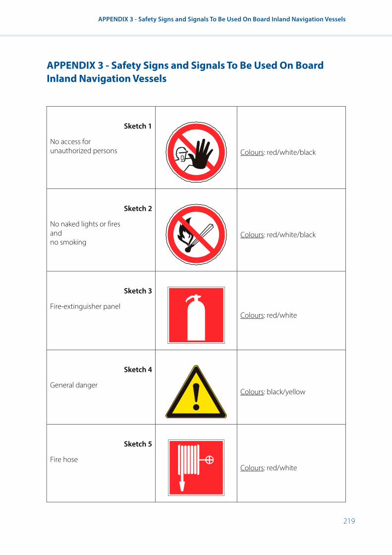
219
APPENDIX 3 - Safety Signs and Signals To Be Used On Board Inland Navigation Vessels
APPENDIX 3 - Safety Signs and Signals To Be Used On Board Inland Navigation Vessels
APPENDIX 3
SAFETY SIGNS AND SIGNALS TO BE USED ON BOARD INLAND NAVIGATION VESSELS
Sketch 1
No access for unauthorized persons
Colours: red/white/black
Sketch 2
No naked lights or fires and no smoking
Colours: red/white/black
Sketch 3
Fire-extinguisher panel
Colours: red/white
Sketch 4
General danger
Colours: black/yellow
Sketch 5
Fire hose
Colours: red/white

220
Resolution No. 61 Revision 2
The pictograms used may differ slightly from or be more detailed than those given in this appendix, provided that their meaning is not modified and that the differences and adaptations do not render them incomprehensible.
Administrations may allow using on board vessels additional graphical safety signs and signals which should as much as possible comply with the symbols recommended in the relevant resolutions of the International Maritime Organization and the standards of the International Organization for Standardization.
Sketch 6
Fire extinguishing equipment
Colours: red/white
Sketch 7
Use ear protectors
Colours: blue/white
Sketch 8
Wear life jacket
Colour: blue/white
The pictograms used may differ slightly from or be more detailed than those given in this appendix, provided that their meaning is not modified and that the differences and adaptations do not render them incomprehensible.
Administrations may allow using on board vessels additional graphical safety signs and signals which should as much as possible comply with the symbols recommended in the relevant resolutions of the International Maritime Organization and the standards of the International Organization for Standardization.

221
APPENDIX 4 - Alternative Manoeuvrability Test Procedures and Criteria in Accordance with 5-2.1
APPENDIX 4 - Alternative Manoeuvrability Test Procedures and Criteria in Accordance with 5-2.1
I. Alternatives
Alternative 1: Administrative Instructions Nos.1 and 2 of annex II of the EU Directive 2006/87/EC laying down technical requirements for inland waterway vessels, as shown below in addendum 4-1.
Status: This alternative is obligatory on waterways subject to the EU Directive 2006/87/EC within the European Union and as far as member States do not apply derogations according to annex IV of the above-mentioned Directive, as well as waterways covered by the Revised Convention for Rhine Navigation of 1868, as amended.
Alternative 2: Requirements set out in section 15, part 1 of the Rules for the Classification and Construction of Inland Navigation Vessels of the Russian River Register, as shown below in addendum 4-2.
Status: This alternative is obligatory on waterways subject to the Code of Inland Water Transport of the Russian Federation.
Alternative 3: Recommendations concerning the Technical and Navigational Characteristics of Pushed Convoys of the Danube Commission as shown below in addendum 4-3.
Status: This alternative is a recommendation.
II. Entries on the ship’s certificate in accordance with 5-2.2
In accordance with 5-2.2 the competent authority on the inspection of vessels shall enter into the ship’s certificate under item 52 which of the above-mentioned alternatives has been applied for the navigation tests.
III. Addenda

222
Resolution No. 61 Revision 2
ADDENDUM 4-1 - Administrative Instructions 1 and 2 of Annex II of the Directive 2006/87/EC
I. Administrative Instruction No. 1 in Accordance with Article 1.07 of Annex II of the Directive - Requirements relating to the capacity for evasive action and turning (Articles 5.09 and 5.10 together with articles 5.02 (1), 5.03 (1), 5.04 and 16.06)
1. General conditions and conditions relating to the evasive action test
1.1 According to article 5.09, vessels and convoys shall be able to take evasive action in good time and the capacity for such action shall be proved by evasive action manoeuvres in the test area referred to in article 5.03. This shall consist of simulated evasive action to port and starboard, under specific conditions in which the limit values of time shall be complied with in order to reach specific turning speeds relative to the evasive action and subsequent correction of course.
The requirements of paragraph 2 shall be satisfied during tests, with a keel clearance equal to at least 20 % of the draught, but not less than 0.50 m.
2. Evasive action test procedure and recording of data
(Diagram in annex 1)
2.1 Evasive action shall be performed as follows:
With the vessel or convoy under way at a constant speed of V0 = 13 km/h relative to the water, at the start of the manoeuvre (time t0 = 0 s, turning speed r = 0°/min, rudder angle δ0 = 0°, selected engine speed kept constant), evasive action to port or starboard is produced by changing the rudder angle. The rudder shall be placed at an angle δ, or the rudder unit at an angle δa in the case of an active rudder, at the start of the manoeuvre, in accordance with the indications given in 2.3. The rudder angle δ (e.g. 20° to starboard) shall be maintained until the value r1 of the turning speed referred to in 2.2 for the corresponding dimensions of the vessel or convoy is reached. When the turning speed r1 is reached, the time t1 should be noted and the rudder set at the same angle on the other side (e.g. 20° to port) so as to complete the evasive action and correct the course, i.e., to reduce the turning speed to r2 = 0 and to raise it again to the value given in 2.2. When the turning speed r2 = 0 is reached, the time t2 shall be noted. When the turning speed r3 given in 2.2 is reached, the helm must be reversed to the same angle δ, so as to complete the turning movement. The time t3 shall be noted. When the turning speed r4 = 0 is reached, the time t4 shall be noted and the vessel or convoy returned to its original course by the requisite rudder movements.

223
APPENDIX 4 - Alternative Manoeuvrability Test Procedures and Criteria in Accordance with 5-2.1
2.2 The following limit values shall be complied with to reach turning speed r according to the dimensions of the vessels or convoys and the depth of water h:
Designation Dimensions of vessels or convoys L × B
Turning speed to be complied with r1 = r3
(°/min)
Limit values for the time t4 (s) in still water and in deep water
δ = 20° δ = 45° 1.2 ≤ h/T ≤ 1,4 1.4 < h/T < 2 h/T > 2
1All self-propelled vessels and single-file convoys ≤ 110 × 11.45 m
20°/min 28°/min 150 s 110 s 110 s
2
Single-file convoys up to 193 × 11.45 m or two-abreast convoys up to 110 × 22.90 m
12°/min 18°/min 180 s 130 s 110 s
3 Two-abreast convoys ≤ 193 × 22.90 m 8°/min 12°/min 180 s 130 s 110 s
4
Two-abreast convoys up to 270 × 22.90 m or three-abreast convoys up to 193 × 34.35 m
6°/min 8°/min * * *
*) As established by the nautical expert
The times t1, t2, t3 and t4 required to reach turning speeds r1, r2, r3 and r4 shall be recorded in the report contained in annex 2. The t4 values shall not exceed the limits established in the table.
2.3 Four evasive manoeuvres at least shall be effected, namely:
• To starboard with a rudder angle δ = 20°
• To port with a rudder angle δ = 20°
• To starboard with a rudder angle δ = 45°
• To port with a rudder angle δ = 45°.
If necessary (e.g. in the case of the non reliability of the values measured or of unsatisfactory manoeuvres), the evasive action shall be repeated. The turning speeds listed in 2.2 and the time limits should be complied with. For active rudders or special types of rudder, a position δ of the rudder unit or rudder angle δ other than δ = 20° and δ = 45° may be selected, according to the expert’s assessment, based on the type of rudder equipment.
2.4 In order to determine the turning speed, a rate-of-turn indicator conforming to the minimum requirements and test conditions for rate-of-turn indicators shall be on board.
2.5 In accordance with article 5.04, the degree of loading during the evasive action test shall be between 70 % and 100 % of the maximum deadweight. If the test is performed with a smaller load, approval for downstream and upstream navigation shall be restricted to that load limit.
The procedure for evasive action and the terms used are represented in a diagram annexed to this document.

224
Resolution No. 61 Revision 2
3. Turning capability
The turning capability of vessels and convoys whose length (L) does not exceed 86 m and width (B) does not exceed 22.90 m shall be considered adequate under article 5.10, in conjunction with article 5.02 (1), when during an upstream turning manoeuvre based on an initial speed relative to the water of 13 km/h and observing the keel clearance conditions of paragraph 1.2, the limit values for stopping facing downstream established in Administrative Instruction No. 2 are complied with.
4. Other requirements
4.1 Notwithstanding paragraphs 1 to 3, the following requirements shall be met:
(a) For manually controlled rudder equipment, a single turn of the wheel shall correspond to a rudder angle of at least 3°;
(b) For mechanically controlled rudder equipment, when the rudder is at maximum depth, it shall be possible to achieve an average angular velocity of 4°/s over the rudder’s entire rotational field.
This requirement shall also be met, with the vessel at full speed, for rudder settings from 35° port to 35° starboard. In addition, it should be ascertained that the rudder holds maximum angle at maximum propelling power. For active rudder equipment or special types of rudder, this provision applies by analogy.
4.2 If any of the additional equipment referred to in article 5.05 has been needed, it shall meet the requirements of chapter 6, and the following particulars shall be entered in item 52 of the ship’s certificate: “Flanking rudders*/forward installation of the rudder*/other equipment* is*/are* necessary to comply with the manoeuvrability requirements of chapter 5”.
* Delete as necessary.
5. Recording of data and reports
The measurements, reports and recording of data shall be carried out according to the procedure set out in annex 2.
Annex 1 Diagram of the evasive action manoeuvre
t 0 = Start of manoeuvre t 1 = Time to reach turning point r 1 t 2 = Time to reach turning speedr 0
(r 2 = 0) t 3 = Time to reach turning speed r 3 t 4 = Time to reach turning speed
r 4 = 0 (end of evasive action) δ = rudder angle [°] r = Angular velocity [°/min]
r3
r1
r
t3 t4t2t0 t1
t
r

225
APPENDIX 4 - Alternative Manoeuvrability Test Procedures and Criteria in Accordance with 5-2.1
Annex 2Report on evasive action and turning capabilities
Inspection commission: ............................................................................................................................................................................................................................................................................................................................................................................................................................
Date: .................................................................................................................................................................................................................................................................................................................................................................................................................................................................................................................
Name: ...........................................................................................................................................................................................................................................................................................................................................................................................................................................................................................................
Name of vessel: ..................................................................................................................................................................................................................................................................................................................................................................................................................................................................
Owner: .......................................................................................................................................................................................................................................................................................................................................................................................................................................................................................................
Type of vessel or convoy: ......................................................................................................................................... Sector: ...........................................................................................................................................................................................................................
L × B [m × m]: ........................................................................................................................................................................................... Scale [m]: ..............................................................................................................................................................................................................
Ttest [m]: ........................................................................................................................................................................................................................ Depth of water h [m]: .........................................................................................................................................................
Load % of maximum(during test) [t]: .................................................................................................................................................................................... deadweight: .................................................................................................................................................................................................
Rate-of-turn indicator
Type: ..............................................................................................................................................................................................................................................................................................................................................................................................................................................................................................................
Type of rudder construction: normal construction/special construction*
Active rudder equipment: yes/no*
Results of evasive action manoeuvres:
Time required t1 to t4 for the evasive
action
Rudder angle δ or δ* at which evasive action commences and turning speed to be complied with r1 = r3
Commentsδ = 20° STAR* δ = ... STAR*
δ = 20° PORT* δ = ... PORT*
δ = 45° STAR* δ = ... STAR*
δ = 45° PORT* δ = ... PORT*
r1 = r3 = ... °/min r1 = r3 = ... °/min
t1(s)
t2(s)
t3(s)
t4(s)
Limit value t4
according to 2.2 Limit value t4 = ... (s)
Turning capability*
Position at start of turning manoeuvre............................................................................................................................................................................................................................................................................................................................................k.p.
Position at end of turning manoeuvre ..............................................................................................................................................................................................................................................................................................................................................k.p.
Steering apparatus
Type of operation: manual/motorized*
Rudder movement for each turn of the wheel*: ........................................................................................................................................................................................................................................................................................................°/s
Angular velocity of the rudder over the whole field*: .................................................................................................................................................................................................................................................................................°/s
Angular velocity of the rudder over the sector* 35° port to 35° starboard: .....................................................................................................................................................................................°/s
* Delete as necessary.

226
Resolution No. 61 Revision 2
II. Administrative instruction No. 2 in accordance with article 1.07 of the Annex II of the Directive - Requirements concerning prescribed maximum speed, stopping capacity and capacity for going astern (Articles 5.06, 5.07 and 5.08 in relation to articles 5.02 (1); 5.03 (1); 5.04 and 16.06)
1. Maximum prescribed speed in accordance with article 5.06
The speed relative to the water is adequate within the meaning of article 5.06, paragraph 1, when it reaches at least 13 km/h. During tests, the following conditions must be met as in the case of the stopping test:
(a) The conditions of keel clearance set out in paragraph 2.1 must be complied with,
(b) The measurements, entries in test reports and registration of test data must be carried out.
2. Stopping capacity and navigability while going astern prescribed in accordance with articles 5.07 and 5.08
2.1 Vessels and convoys are able to stop facing downstream in good time in accordance with article 5.07, paragraph 1, when this is proved in the course of the test of stopping relative to the bank facing downstream at an initial speed through the water of 13 km/h, with a keel clearance equal to at least 20 % of the draught but not less than 0.50 m.
(a) In running water (current velocity of: 1.5 m/s), stopping relative to the water shall be effected over a distance measured relative to the bank of:
550 m for vessels and convoys of:
• length L > 110 m and
• width B > 11.45 m
or
480 m for vessels and convoys of:
• length L ≤ 110 m and
• width B ≤ 11.45 m.
The stopping manoeuvre is completed on coming to a stop relative to the bank.
(b) In still water (current velocity of less than 0.2 m/s), stopping relative to the water must be effected over a distance, measured relative to the bank of:
not more than 350 m for vessels and convoys of:
• length L > 110 m and
• width B > 11.45 m
or
305 m for vessels and convoys of:
• length L ≤ 110 m and
• width B ≤ 11.45 m.
227
APPENDIX 4 - Alternative Manoeuvrability Test Procedures and Criteria in Accordance with 5-2.1
In still water, a test shall also be performed to establish that a speed of not less than 6.5 km/h can be reached when going astern.
The measurements, inclusion in test reports and recording of the test data referred to in (a) or (b) shall be effected in accordance with the procedure set out in annex 1.
Throughout the test, the vessel or the convoy shall have adequate manoeuvrability.
2.2 Under article 5.04, during the test, vessels shall be loaded as far as possible to 70-100 % of their deadweight. The degree of loading shall be evaluated in accordance with annex 2. When the load of the vessel or the convoy is less than 70 % at the time of the test, the permitted displacement in downstream navigation shall be determined on the basis of the actual load, provided that the limit values of paragraph 2.1 are respected.
2.3 If the actual values of the initial speed and current velocity at the time of the test do not meet the condition established in 2.1, the results obtained shall be evaluated according to the procedure described in annex 2.
If the permitted difference in respect of the initial speed of 13 km/h shall be not more than ± 1 km/h, and the current velocity in running water must be between 1.3 and 2.2 m/s, otherwise the tests must be repeated.
2.4. The maximum permitted displacement for vessels and convoys in downstream navigation shall be established on the basis of the tests and entered in the ship’s certificate.

228
Resolution No. 61 Revision 2
ANNEX 1 - Measurement, report and recording of data collected during stopping manoeuvre tests
1. Stopping manoeuvre
The vessels and convoys referred to in chapter 5 shall perform a test in running water or in still water, in a test sector, to prove that they are capable of stopping facing downstream with the help of their propelling installations without the use of anchors. The stopping manoeuvre shall, in principle, be conducted in accordance with figure 1. It begins when the vessel is travelling at a steady speed - 13 km/h relative to the water, as far as possible be reversing the engines from “ahead” to “astern” (point Ⓐ of the order “stop”) and is completed when the vessel is stationary relative to the bank (point Ⓔv = 0 relative to the bank or point Ⓓ = point Ⓔv = 0 relative to the water and relative to the bank if the stopping manoeuvre is carried out in still water.
When stopping manoeuvres are carried out in running water, the position and the moment of stopping relative to the water should also be recorded (the boat moves at the speed of the current; point Ⓓv = 0 relative to the water).
The data measured shall be entered in a report from as illustrated in the graph of table 1. Before the stopping manoeuvre takes place, the fixed data should be entered at the top of the form.
The average speed of the current (vstr) in the navigable channel shall be determined, if known, on the basis of the reading scale, or by measuring the movement of a floating body, and shall be entered in the report.
In principle, the use of current metres is permitted to determine the speed of the vessel relative to the water during the stopping manoeuvre, if this enables the sequence of movements and measurements described above to be recorded.
2. Recording the data measured and entering them in the report (table 1)
For the stopping manoeuvre, the initial speed relative to the water must first of all be determined. This can be done by measuring the time taken to travel between two markers on land. In running water, the average speed of the current must be taken into consideration.
The stopping manoeuvre is initiated by the order “stop” Ⓐ, given on passing a marker on land. Passage of the land marker is recorded at a point perpendicular to the axis of the vessel and must be entered in the report. The passage of all other land markers during the stopping manoeuvre is recorded in the same way and each marker (e.g. kilometre post) and the time it is passed are noted in the report.
The values measured must, if possible, be recorded at intervals of 50 m. In each case, note should be taken of the time when points Ⓑ and Ⓒ – if possible – as well as points Ⓓ and Ⓔ are reached and the position evaluated. The data concerning the number of revolutions need not be recorded in the report, but should be noted to permit more accurate control of the initial speed.
3. Description of the execution of the stopping manoeuvre
The execution of the stopping manoeuvre according to figure 1 shall be presented in the form of a diagram. First of all, the distance-time curve must be plotted using the measurements entered in the rest report and points Ⓐ and Ⓔ marked. It will then be possible to determine the average speed between two measurement points and to plot the speed/time curve.
This is done as follows (see figure 1):
By determining the quotient of the difference of position over the difference in time Δs/Δt, the average speed of the vessel for this period may be calculated.
During the interval between 0 s and 10 s, the distance from 0 m to 50 m is covered.
Δs/Δt = 50 m/10 s – 5.0 m/s = 18.0 km/h

229
APPENDIX 4 - Alternative Manoeuvrability Test Procedures and Criteria in Accordance with 5-2.1
This value is entered as the average speed for a 5 s. abscissa.
During the second interval, from 10 s to 20 s, a distance of 45 m is covered.
Δs/Δt = 45 m/10 s = 4.5 m/s = 16.2 km/h
Perpendicular to marker Ⓓ, the vessel has stopped relative to the water i.e. current speed is approximately 5 km/h.
Figure 1Execution of the stopping manoeuvre
Key to symbols
Ⓐ “stop” order
Ⓑ propeller stopped
Ⓒ propeller in reverse
Ⓓ v = 0 relative to the water
Ⓔ v = 0 relative to the bank
v speed of vessel
vL v relative to the bank
s distance covered relative to the bank
t time elapsed

230
Resolution No. 61 Revision 2
Tabl
e 1:
Rep
ort o
f the
sto
ppin
g m
anoe
uvre
Insp
ectio
n Co
mm
issio
n:
.......
........
........
........
........
........
........
........
. Ca
tego
ry o
f ves
sel o
r con
voy:
...
........
........
........
........
........
.....
Sect
or: .
........
........
........
........
........
........
........
........
........
........
...
........
........
........
........
........
........
........
.....
L ×
B [m
]: ...
........
........
........
........
........
.....
Scal
e
[m]:
.......
........
........
..
Dat
e:
.......
........
........
........
........
........
........
........
. T
test [m
in]:
.......
........
........
........
........
........
. D
epth
of w
ater
[m
]: ...
........
........
......
Nam
e:
.......
........
........
........
........
........
........
........
. Lo
adin
g Te
st [t
]: ...
........
........
........
........
........
.....
Gra
dien
t [m
/km
]: ...
........
........
......
Jour
ney
No.
: ...
........
........
........
........
........
........
........
.....
% o
f max
imum
dea
dwei
ght:
.......
........
........
........
........
........
. V S
TR
[km
/h]:
.......
........
........
..
...
........
........
........
........
........
........
........
.....
Pow
er o
f pro
pulsi
on e
ngin
es P
B [kW
]: ...
........
........
........
........
........
.....
[m
/s]:
.......
........
........
..
...
........
........
........
........
........
........
........
.....
Prop
ulsio
n sy
stem
, ann
ex 2
, tab
le 2
: ...
........
........
........
........
........
.....
Max
. wat
er
[m3 ]:
...
........
........
........
........
........
........
........
.....
...
........
........
........
........
........
.....
disp
lace
men
t
.......
........
........
..
PLA
CE
[km
poi
nt]
TIM
E [s
]∆
s [m
]∆
t [s
]v L
[k
m/h
]n
[min
-1]
OBS
ERVA
TIO
NS
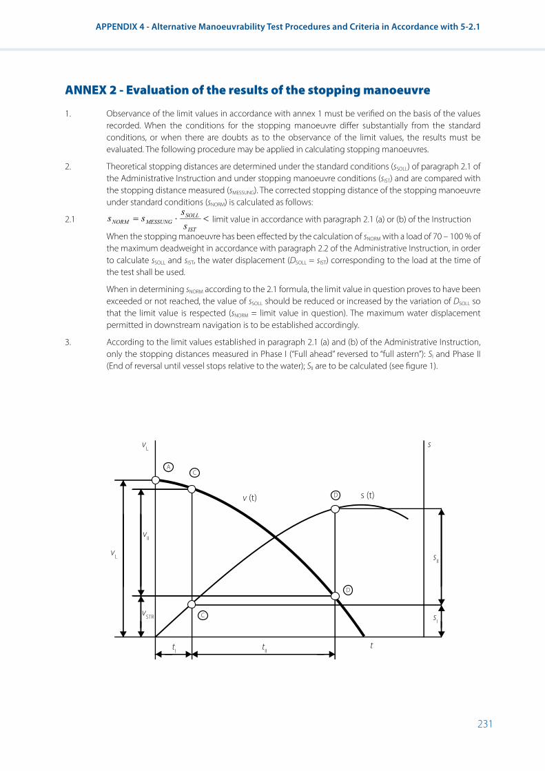
231
APPENDIX 4 - Alternative Manoeuvrability Test Procedures and Criteria in Accordance with 5-2.1
ANNEX 2 - Evaluation of the results of the stopping manoeuvre
1. Observance of the limit values in accordance with annex 1 must be verified on the basis of the values recorded. When the conditions for the stopping manoeuvre differ substantially from the standard conditions, or when there are doubts as to the observance of the limit values, the results must be evaluated. The following procedure may be applied in calculating stopping manoeuvres.
2. Theoretical stopping distances are determined under the standard conditions (sSOLL) of paragraph 2.1 of the Administrative Instruction and under stopping manoeuvre conditions (sIST) and are compared with the stopping distance measured (sMESSUNG). The corrected stopping distance of the stopping manoeuvre under standard conditions (sNORM) is calculated as follows:
2.1
<⋅=IST
SOLLMESSUNGNORM s
sss
Annex 2 EVALUATION OF THE RESULTS OF THE STOPPING MANOEUVRE
1. Observance of the limit values in accordance with annex 1 must be verified on the basis of the values recorded. When the conditions for the stopping manoeuvre differ substantially from the standard conditions, or when there are doubts as to the observance of the limit values, the results must be evaluated. The following procedure may be applied in calculating stopping manoeuvres.
2. Theoretical stopping distances are determined under the standard conditions (sSOLL) of paragraph 2.1 of the Administrative Instruction and under stopping manoeuvre conditions (sIST) and are compared with the stopping distance measured (sMESSUNG). The corrected stopping distance of the stopping manoeuvre under standard conditions (sNORM) is calculated as follows:
2.1 limit value in accordance with paragraph 2.1 (a) or (b) of the Instruction
When the stopping manoeuvre has been effected by the calculation of sNORM with a load of 70 – 100% of the maximum deadweight in accordance with paragraph 2.2 of the Administrative Instruction, in order to calculate sSOLL and sIST, the water displacement (DSOLL = DIST) corresponding to the load at the time of the test shall be used.
When in determining sNORM according to the 2.1 formula, the limit value in question proves to have been exceeded or not reached, the value of sSOLL should be reduced or increased by the variation of DSOLL so that the limit value is respected (sNORM = limit value in question). The maximum water displacement permitted in downstream navigation is to be established accordingly.
3. According to the limit values established in paragraph 2.1 (a) and (b) of the Administrative Instruction, only the stopping distances measured in Phase I (“Full ahead” reversed to “full astern”): SI and Phase II (End of reversal until vessel stops relative to the water); SII are to be calculated (see figure 1).
limit value in accordance with paragraph 2.1 (a) or (b) of the Instruction
When the stopping manoeuvre has been effected by the calculation of sNORM with a load of 70 – 100 % of the maximum deadweight in accordance with paragraph 2.2 of the Administrative Instruction, in order to calculate sSOLL and sIST, the water displacement (DSOLL = sIST) corresponding to the load at the time of the test shall be used.
When in determining sNORM according to the 2.1 formula, the limit value in question proves to have been exceeded or not reached, the value of sSOLL should be reduced or increased by the variation of DSOLL so that the limit value is respected (sNORM = limit value in question). The maximum water displacement permitted in downstream navigation is to be established accordingly.
3. According to the limit values established in paragraph 2.1 (a) and (b) of the Administrative Instruction, only the stopping distances measured in Phase I (“Full ahead” reversed to “full astern”): SI and Phase II (End of reversal until vessel stops relative to the water); SII are to be calculated (see figure 1).
AC
C
D
D
s
s (t)v (t)
vL
t
vL
tI tII
sII
sI
vII
vSTR

232
Resolution No. 61 Revision 2
One total stopping distance is then:
3.1 Sges = SI + SII
4. The stopping distances alone are to be calculated as follows: Calculation formulae: with the following coefficients
4.1 𝑆𝑆𝑆𝑆I = 𝑘𝑘𝑘𝑘1 × 𝑣𝑣𝑣𝑣L × 𝑡𝑡𝑡𝑡l 𝑡𝑡𝑡𝑡l ≤ 20 s - k1 according to table 1
4.2 𝑆𝑆𝑆𝑆II = 𝑘𝑘𝑘𝑘2 × 𝑣𝑣𝑣𝑣II2 × 𝐷𝐷𝐷𝐷 × 𝑔𝑔𝑔𝑔𝑘𝑘𝑘𝑘2 × 𝐹𝐹𝐹𝐹POR+𝑅𝑅𝑅𝑅TmII × 𝑅𝑅𝑅𝑅G
− [𝑘𝑘𝑘𝑘4 + 𝑣𝑣𝑣𝑣STR𝑣𝑣𝑣𝑣II
� - k2, k3, k4 according to table 1
4.3 𝑅𝑅𝑅𝑅TmII = �𝑅𝑅𝑅𝑅T 𝑣𝑣𝑣𝑣2� � × ( 𝑘𝑘𝑘𝑘7 × 𝑘𝑘𝑘𝑘6 × (𝑣𝑣𝑣𝑣L − 𝑣𝑣𝑣𝑣STR) )2 - k5, k7 according to table 1 - RT/v2 according to table 3
4.4 𝑅𝑅𝑅𝑅G = 𝑖𝑖𝑖𝑖 × 𝐷𝐷𝐷𝐷 × ρ × 𝑔𝑔𝑔𝑔 × 10−6 4.5 𝑣𝑣𝑣𝑣II = 𝑘𝑘𝑘𝑘6 × (𝑣𝑣𝑣𝑣L − 𝑣𝑣𝑣𝑣STR) - k6 according to table 1 4.6 𝐹𝐹𝐹𝐹POR = 𝑓𝑓𝑓𝑓 × 𝑃𝑃𝑃𝑃8 - f according to table 2
4.7 𝑡𝑡𝑡𝑡II = 𝑠𝑠𝑠𝑠II𝑣𝑣𝑣𝑣II − �𝑘𝑘𝑘𝑘4+
𝑣𝑣𝑣𝑣STR𝑣𝑣𝑣𝑣II
�
- k4 according to table 1
In formulae 4.1 to 4.7:
vL Speed relative to the bank at the start of reversal (m/s)
tI Reversal time (s)
vII Speed relative to the water at the end of reversal (m/s)
D Water displacement (m3)
FPOR Tractive force at the fixed point, in reverse (kN)
PB Power of propulsion engine (kW)
RTmII Average resistance during phase II, to be determined using the diagram for calculating resistance
(kN)
RG Resistance to gradient (kN)
i Gradient in m/km (in the absence of date = 0.16) (m/km)
vSTR Average speed of current (m/s)
g Acceleration of gravity (9.81) (m/s2)
ρ Density of water, ρ fresh water = 1,000 (kg/m3)
T Maximum deadweight (of vessel or convoy) (m)
h Depth of water (m)
B Width (m)
L Length (m)

233
APPENDIX 4 - Alternative Manoeuvrability Test Procedures and Criteria in Accordance with 5-2.1
The coefficients for the formulae 4.1, 4.2, 4.3, 4.4, 4.5, 4.6 and 4.7 can be found in tables below.
Table 1: k factors for
a. SELF-PROPELLED VESSELS and CONVOYS, single file
b. Two-abreast CONVOYS
c. Three-abreast CONVOYS
(a) (b) (c) Units
k1 0.95 0.95 0.95 -
k2 0.115 0.120 0.125 kg × s2
m⁴
k3 1.20 1.15 1.10 -
k4 0.48 0.48 0.48 -
k6 0.90 0.85 0.80 -
k7 0.58 0.55 0.52 -
Table 2: Coefficient f for ratio between the tractive force at the fixed point in reverse and the power of the propulsion engines
Propulsion system f Units
Modern nozzles with rounded rear edge 0.118 kN/kW
Old nozzles with sharp rear edge 0.112 kN/kW
Propellers with no nozzle 0.096 kN/kW
Steering propellers with nozzles (generally sharp rear edge) 0.157 kN/kW
Steering propellers with no nozzles 0.113 kN/kW

234
Resolution No. 61 Revision 2
Table 3: Diagram concerning the calculation of resistance
To determine the value of RT/v2 in relation to 𝐷𝐷𝐷𝐷1/3 [𝐵𝐵𝐵𝐵 + 2𝑇𝑇𝑇𝑇]:
𝑅𝑅𝑅𝑅T𝑣𝑣𝑣𝑣2�
�kN × s2
m2 �
𝐷𝐷𝐷𝐷1/3 [𝐵𝐵𝐵𝐵 + 2𝑇𝑇𝑇𝑇]

235
APPENDIX 4 - Alternative Manoeuvrability Test Procedures and Criteria in Accordance with 5-2.1
EXAMPLES OF THE APPLICATION OF ANNEX 2 (for the use of the results of the stopping tests)
EXAMPLE I
1. Data relating to the convoy and its components
Formation: ordinary self-propelled vessel with a (Europa IIa) pushed lighter coupled abreast
L [m] B [m] Tmax [m] Tgf*max [t] Dmax [m3] PB [kW]
Self-propelled vessel 110 11.4 3.5 2 900 3 731 1 500
Pushed lighter 76.5 11.4 3.7 2 600 2 743 –
Convoy 110 22.8 3.7 5 500 6 474 1 500
Propulsion system of the self-propelled vessel: modern nozzles with rounded rear edge
* Tgf = deadweight.
2. Values measured during the stopping manoeuvre
Speed of current: VSTRIST = 1.4 m/s ≈5.1 km/h
Speed of vessel: (relative to the water) VSIST = 3.5 m/s ≈12.5 km/h
Speed of vessel: (relative to the bank): VLIST = 4.9 m/s ≈17.6 km/h
Reversal time (measured) (point Ⓐ to Ⓒ) : t1 = 16 s
Stopping distance relative to water: (point Ⓐ to Ⓓ) : sMESSUNG =340 m
Degree of loading (possibly estimated): DIST = 5 179 m3 ≈0.8 × Dmax
Actual draught of convoy: TIST = 2.96 m ≈0.8 × Tmax
3. Limit value according to 2.1 (a) or (b) to be compared with sNORM
Since B > 11.45 m and since the convoy is in running water, the following is applicable for this convoy under 2.1 (a):
sNORM ≤ 550 m
4. Determination of corrected stopping distance compared to standard conditions
– Measurement according to annex 1 (see 2)
sMESSUNG = 340 m – Calculation to be made:
sIST sum of
SIIST (according to formula 4.1 of annex 2 with VLIST)
– SIIST (according to formulae 4.2, 4.3, 4.4, 4.5 and 4.6 of annex 2 with real speeds VIIIST, VSTRIST, DIST)

236
Resolution No. 61 Revision 2
sSOLL sum of
sISOLL (according to formula 4.1 or annex 2 with vLSOLL)
and sIISOLL (according to formulae 4.2 to 4.6 of annex 2 with the standard speeds according to 2.1 of the Administrative Instruction and given that the degree of loading is greater than 70% (= 80%)): DSOLL = DIST and TSOLL = TIST
- to be checked:
𝑠𝑠𝑠𝑠NORM = 𝑠𝑠𝑠𝑠MESSUNG × 𝑠𝑠𝑠𝑠SOLL𝑠𝑠𝑠𝑠IST
≤ 555 m
4.1 Initial data for the calculation
Table 1
for sIIST and sISOLL k1 = 0.95
for sIIIST and sIISOLL k2 = 0.12
k3 = 1.15 k4 = 0.48 k6 = 0.85 k7 = 0.55
Table 2 (for modern nozzles with rounded rear edge)
f = 0.118
4.2 Calculation of sIST
(a) sIIST with the values measured during the stopping manoeuvre (formula 4.1)
𝑠𝑠𝑠𝑠IIST = 𝑘𝑘𝑘𝑘1 × 𝑣𝑣𝑣𝑣LIST × 𝑡𝑡𝑡𝑡IIST
𝑠𝑠𝑠𝑠IIST = 0.95 × 4.9 × 16 = 74.5 m
(b) Formula for sIIIST
𝑠𝑠𝑠𝑠IIIST = 𝑘𝑘𝑘𝑘2 × 𝑣𝑣𝑣𝑣2IIIST ×𝐷𝐷𝐷𝐷IST × g
𝑘𝑘𝑘𝑘3× 𝐹𝐹𝐹𝐹POR + 𝑅𝑅𝑅𝑅TmIIIST 𝑅𝑅𝑅𝑅𝐺𝐺𝐺𝐺× �𝑘𝑘𝑘𝑘4 +
𝑣𝑣𝑣𝑣STRIST𝑣𝑣𝑣𝑣IIIST
�
(c) Calculation of RTmIIIST according to table 3 and formula 4.3 of annex 2
𝐷𝐷𝐷𝐷IST1/3 = 51791/3 = 17.3 [m]
𝐷𝐷𝐷𝐷IST1/3 = (𝐵𝐵𝐵𝐵 + 2 × 𝑇𝑇𝑇𝑇IST) = 17.3 × (22.8 + 5.92) = 495.8 [m2]
according to table 3 𝑅𝑅𝑅𝑅T 𝑣𝑣𝑣𝑣2
= 10.8 � kN × s2
m2 �
𝑣𝑣𝑣𝑣LIST − 𝑣𝑣𝑣𝑣STRIST = 4.9 − 1.4 = 3.5 m/s
𝑅𝑅𝑅𝑅TmIIIST = 𝑅𝑅𝑅𝑅T𝑣𝑣𝑣𝑣2
× �𝑘𝑘𝑘𝑘7 × 𝑘𝑘𝑘𝑘6 × �𝑣𝑣𝑣𝑣LIST − 𝑣𝑣𝑣𝑣STRIST��2
= 10.8 × (0.55 × 0.85 × 3.5)2 = 28.8 [kN]
(d) Calculation of resistance to gradient RG according to formula 4.4

237
APPENDIX 4 - Alternative Manoeuvrability Test Procedures and Criteria in Accordance with 5-2.1
𝑅𝑅𝑅𝑅G = 10−6× (0.16 × 𝐷𝐷𝐷𝐷IST × 𝜌𝜌𝜌𝜌 × g) = 10−6× (0.16 × 5179 × 1000 × 9.81) = 8.13 [kN]
(e) Calculation of vIIIST according to formula 4.5
𝑣𝑣𝑣𝑣IIIST = 𝑘𝑘𝑘𝑘6 × �𝑣𝑣𝑣𝑣LIST − 𝑣𝑣𝑣𝑣STRIST� = (0.85 ×3.5) = 2.97 [m/s]
𝑣𝑣𝑣𝑣2IIIST = 8.85 [m/s]2
(f) Calculation of FPOR according to formula 4.6 and table 2
𝐹𝐹𝐹𝐹POR = 0.118 × 1500 = 177 [kN]
(g) Calculation of sIIIST using formula (b) and the result of (c), (d), (e) and (f)
𝑠𝑠𝑠𝑠IIIST = 0.12 × 8.85 × 9.81 × �0.48+ 1.4
2.97�
1.15 × 177+28.8−8.13 × 5179
𝑠𝑠𝑠𝑠IIIST = 228.9 [m]
(h) Calculation of total distance according to formula 3.1
𝑠𝑠𝑠𝑠IST = 74.51 + 228.9 = 303.4 [m]
Notes: Given that the term (RTmII – RG) as a function of D with 20.67 kN is obviously relatively small compared with 𝑘𝑘𝑘𝑘3×𝐹𝐹𝐹𝐹PDR with 203.55 kN, for simplification purposes, sII can be taken as proportional to D, i.e. sII = Constant x D.
4.3 Calculation of sSOLL
Initial values 𝑣𝑣𝑣𝑣STRSOLL = 1.5 m/s = 5.4 km/h 𝐷𝐷𝐷𝐷SOLL = 𝐷𝐷𝐷𝐷IST = 5179 m3
𝑣𝑣𝑣𝑣SSOLL = 3.6 m/s = 13 km/h 𝑇𝑇𝑇𝑇SOLL = 𝑇𝑇𝑇𝑇IST = 2.96 m
𝑣𝑣𝑣𝑣LSOLL = 5.1 m/s = 18.4 km/h
(a) 𝑠𝑠𝑠𝑠ISOLL = 𝑘𝑘𝑘𝑘1 × 𝑣𝑣𝑣𝑣LSOLL × 𝑡𝑡𝑡𝑡I
𝑆𝑆𝑆𝑆ISOLL = 0.95 × 5.1 × 16 = 77.5 [m]
(b) 𝑆𝑆𝑆𝑆IISOLL = 𝑘𝑘𝑘𝑘2 × 𝑣𝑣𝑣𝑣2IISOLL × 𝐷𝐷𝐷𝐷SOLL × g𝑘𝑘𝑘𝑘3 × 𝐹𝐹𝐹𝐹POR × 𝑅𝑅𝑅𝑅TmIISOLL × 𝑅𝑅𝑅𝑅G
× �𝑘𝑘𝑘𝑘4 + 𝑣𝑣𝑣𝑣STRSOLL𝑣𝑣𝑣𝑣IISOLL
�
(c) calculation of RTmIISOLL
𝑅𝑅𝑅𝑅T𝑣𝑣𝑣𝑣2
= 10.8 �kN × s2
m2 � as under 4.2, since B, D and T are unchanged.
𝑣𝑣𝑣𝑣LSOLL − 𝑣𝑣𝑣𝑣STRSOLL = 3.6 [m/s]
𝑅𝑅𝑅𝑅TmIISOLL =𝑅𝑅𝑅𝑅T𝑣𝑣𝑣𝑣2
× �𝑘𝑘𝑘𝑘7 × 𝑘𝑘𝑘𝑘6 × �𝑣𝑣𝑣𝑣LSOLL − 𝑣𝑣𝑣𝑣STRSOLL��2
= 10.8 × (0.55 × 0.85 × 3.6)2 = 30.99 [kN]
(d) Resistance to the gradient RG as in 4.2
(e) Calculation of vIISOLL
𝑣𝑣𝑣𝑣IISOLL = 𝑘𝑘𝑘𝑘6 × �𝑣𝑣𝑣𝑣LSOLL − 𝑣𝑣𝑣𝑣STRSOLL� = 0.85 × 3.6 = 3.06 [m/s], 𝑣𝑣𝑣𝑣2IISOLL = 9.36 [m/s]2
(f) FPOR as in 4.2.

238
Resolution No. 61 Revision 2
(g) Calculation of sIISOLL using formula (b) and the result from (c) to (f)
𝑠𝑠𝑠𝑠IISOLL = 0.12 × 9.36 × 9.81 × �0.48+ 1.5
3.06�
1.15 × 177 × 30.99−8.13 × 5179
= 0.0472ConstantSOLL
× 5179 = 244.5 [m]
(h) Calculation of total distance
𝑠𝑠𝑠𝑠SOLL = 𝑠𝑠𝑠𝑠ISOLL + 𝑠𝑠𝑠𝑠IISOLL = 77.5 + 244.5 = 322 [m]
4.4 Verification that the permissible stopping distance under standard conditions sNORM is respected
according to formula 2.1 of annex 2
𝑠𝑠𝑠𝑠NORM = 𝑠𝑠𝑠𝑠MESSLUNG × 𝑠𝑠𝑠𝑠SOLL𝑠𝑠𝑠𝑠IST
= 340 × 322303.4
= 360.8 [m] < 550 [m]
Conclusion:
The permissible limit value is far from being reached, i.e.: - admission to downstream navigation is possible without problems given the degree
of loading submitted (0.8 x Dmax), - a higher degree of loading is possible and may be calculated according to 5 below.
5. Possible increase of DIST in downstream navigation
(𝑠𝑠𝑠𝑠NORM)Limit = 𝑠𝑠𝑠𝑠MESSUNG × (𝑠𝑠𝑠𝑠SOLL)Limit𝑠𝑠𝑠𝑠IST
= 550 [m]
(𝑠𝑠𝑠𝑠SOLL)Limit = 550 × 𝑠𝑠𝑠𝑠IST𝑠𝑠𝑠𝑠MESSUNG
= 550 × 303.4340
= 490.8 [m]
Where 𝑠𝑠𝑠𝑠IISOLL = ConstantSOLL × 𝐷𝐷𝐷𝐷 according to the notes under 4.2
(𝑠𝑠𝑠𝑠SOLL)Limit = �𝑠𝑠𝑠𝑠ISOLL + 𝑠𝑠𝑠𝑠IISOLL�Limit = 𝑠𝑠𝑠𝑠ISOLL + 0.0472 × (𝐷𝐷𝐷𝐷SOLL)Limit
is obtained, hence
(𝐷𝐷𝐷𝐷SOLL)Limit = �𝑠𝑠𝑠𝑠ISOLL�Limit
− 𝑠𝑠𝑠𝑠ISOLL0.0472
= 490.8−77.50.0472
= 8756 [m3]
As a result:
Since (𝐷𝐷𝐷𝐷SOLL)Limit > 𝐷𝐷𝐷𝐷max (8756 > 6474) this formation (see 1) may be permitted in downstream navigation with a full load.
EXAMPLE II
1. Data concerning the vessels and the convoy
Formation: self-propelled vessel-pusher with 2 leading pushed lighters and 1 pushed lighter coupled abreast

239
APPENDIX 4 - Alternative Manoeuvrability Test Procedures and Criteria in Accordance with 5-2.1
L [m] B [m] Tmax [m] Tgf*max [t] Dmax [m3] PB [kW]
Self-propelled vessel 110 11.4 3.5 2900 3731 1500
Each pushed lighter 76.5 11.4 3.7 2600 2743 -
Convoy 186.5 22.8 3.7 10700 11960 1500
Propulsion system of the self-propelled vessel: modern nozzles with rounded rear edge.
* Tgf = deadweight
2. Values measured during the stopping manoeuvre
Speed of current 𝑣𝑣𝑣𝑣STRIST = 1.4 m s⁄ ≈ 5.1 km h⁄
Speed of vessel (relative to the water) 𝑣𝑣𝑣𝑣sIST = 3.5 m s⁄ ≈ 12.5 km h⁄
Speed of vessel (relative to the bank) 𝑣𝑣𝑣𝑣LIST = 4.9 m s⁄ ≈ 17.6 km h⁄
Duration of reversal measured (point ○○A to ○○C ) 𝑡𝑡𝑡𝑡I = 16 s
Stopping distance relative to the water (point ○○A to ○○D ) 𝑠𝑠𝑠𝑠MESSUNG = 580 m
Load situation (possibly estimated) 𝐷𝐷𝐷𝐷IST = 9568 m3 ≈ 0.8 𝐷𝐷𝐷𝐷max
Actual draught of convoy 𝑇𝑇𝑇𝑇IST = 2.96 ≈ 0.8 𝑇𝑇𝑇𝑇max
3. Limit value according to paragraph 2.1 (a) or (b) of the Administrative Instruction to be compared with sNORM
Since B > 11.45 and the convoy is in running water, the following applies for this convoy under 2.1 (a):
𝑠𝑠𝑠𝑠NORM ≤ 550 m
4. Determination of the corrected stopping distance compared with standard conditions
- Measurement: 𝑠𝑠𝑠𝑠MESSUNG = 340 m
- calculations to be made:
sIST sum of
sIIST (according to formula 4.1 of annex 2 with vLIST)
and sIIIST (according to formulae 4.2, 4.3, 4.4, 4.5 and 4.6 of annex 2 with real speeds vIST (see under 2 above) and DIST)
𝑠𝑠𝑠𝑠SOLL ∶ 𝑠𝑠𝑠𝑠𝑠𝑠𝑠𝑠𝑚𝑚𝑚𝑚 𝑠𝑠𝑠𝑠ISOLL + 𝑠𝑠𝑠𝑠IISOLL (according to formulae 4.1 to 4.6 of annex 2 with standard speeds and in conformity of annex 2, because the degree of loading > 70%, where 𝐷𝐷𝐷𝐷SOLL = 𝐷𝐷𝐷𝐷IST and 𝑇𝑇𝑇𝑇SOLL = 𝑇𝑇𝑇𝑇IST)
- to be verified:
𝑠𝑠𝑠𝑠NORM = 𝑠𝑠𝑠𝑠MESSUNG × 𝑠𝑠𝑠𝑠SOLL𝑠𝑠𝑠𝑠IST
≤ 550 m, otherwise
- calculate:
L [m] B [m] Tmax [m] Tgf*max [t] Dmax [m3] PB [kW]
Self-propelled vessel 110 11.4 3.5 2 900 3 731 1 500
Each pushed lighter 76.5 11.4 3.7 2 600 2 743 –
Convoy 186.5 22.8 3.7 10 700 11 960 1 500

240
Resolution No. 61 Revision 2
𝑠𝑠𝑠𝑠∗NORM = 550 m by reduction of 𝐷𝐷𝐷𝐷IST 𝑡𝑡𝑡𝑡𝑡𝑡𝑡𝑡 𝐷𝐷𝐷𝐷∗
4.1 Coefficients for the calculation of annex 2 in table 1
for 𝑠𝑠𝑠𝑠IIST and 𝑠𝑠𝑠𝑠ISOLL k1 = 0.95
for 𝑠𝑠𝑠𝑠IIST and 𝑠𝑠𝑠𝑠ISOLL k2 = 0.12
k3 = 1.15 k4 = 0.48 k5 = 0.85 k7 = 0.55
From table 2 (for modern nozzles with rounded rear edge)
f = 0.118
4.2 Calculation of 𝑠𝑠𝑠𝑠IIST
(a) 𝑠𝑠𝑠𝑠IIST with the values measured during the stopping tests (formula 4.1):
𝑠𝑠𝑠𝑠IIST = 𝑘𝑘𝑘𝑘1 × 𝑣𝑣𝑣𝑣LIST × 𝑡𝑡𝑡𝑡IIST
𝑠𝑠𝑠𝑠IIST = 0.95 × 4.8 × 16 = 73 [m]
(b) formula for 𝑠𝑠𝑠𝑠IIIST 𝑠𝑠𝑠𝑠IIIST = 𝑘𝑘𝑘𝑘2 × 𝑣𝑣𝑣𝑣2IIIST × 𝐷𝐷𝐷𝐷IST × 𝑔𝑔𝑔𝑔
𝑘𝑘𝑘𝑘2 × 𝐹𝐹𝐹𝐹POR+𝑅𝑅𝑅𝑅TmIIIST− 𝑅𝑅𝑅𝑅G × �𝑘𝑘𝑘𝑘4 +
𝑣𝑣𝑣𝑣STRIST𝑣𝑣𝑣𝑣IIIST
�
(c) Calculation of 𝑅𝑅𝑅𝑅TmIIIST according to table 3 and formula 4.3 of annex 2
𝐷𝐷𝐷𝐷IST13� = 95681 3� = 21.2 [m]
𝐷𝐷𝐷𝐷IST13� × (𝐵𝐵𝐵𝐵 + 2 × 𝑇𝑇𝑇𝑇IST) = 21.2 × (22.8 − 5.92) = 609 [m2]
of table 3 𝑅𝑅𝑅𝑅T𝑣𝑣𝑣𝑣2
= 14.0 � kN × s2
m2 �
𝑣𝑣𝑣𝑣LIST − 𝑣𝑣𝑣𝑣STRIST = 4.8 − 1.4 = 3.4 [m/s]
𝑅𝑅𝑅𝑅TmIIIST = 𝑅𝑅𝑅𝑅T𝑣𝑣𝑣𝑣2
× �𝑘𝑘𝑘𝑘7 × 𝑘𝑘𝑘𝑘6 ×�𝑣𝑣𝑣𝑣LIST × 𝑣𝑣𝑣𝑣STRIST��2
= 14.0 × (0.55 ×0.85 ×3.4)2 = 35.4 [kN]
(d) Calculation of resistance to the gradient RG according to formula 4.4 of annex 2. 𝑅𝑅𝑅𝑅G = 10−6 × (0.6 × 𝐷𝐷𝐷𝐷IST × ρ ×𝑔𝑔𝑔𝑔) = 10−6 × (0.16 ×9568 ×1000 ×9.81) = 15.02 [kN]
(e) Calculation of 𝑣𝑣𝑣𝑣IIIST according to formula 4.5 of annex 2
𝑣𝑣𝑣𝑣IIIST = 𝑘𝑘𝑘𝑘6 × �𝑣𝑣𝑣𝑣LIST × 𝑣𝑣𝑣𝑣STRIST� = 2.89 [m/s]
𝑣𝑣𝑣𝑣IIIST = 8.35 [m/s]2
(f) Calculation of 𝐹𝐹𝐹𝐹POR according to formula 4.6 and table 2 𝐹𝐹𝐹𝐹POR = 0.118 ×1500 = 177 [kN]
(g) Calculation of 𝑠𝑠𝑠𝑠IIIST using formula (b) and the result of (c), (d), (e) and (f)
𝑠𝑠𝑠𝑠IIIST = 0.12 × 8.35 ×9.81 �0.48+ 1.4
2.89�
1.15 × 177 + 35.4 − 15.02 ×9568

241
APPENDIX 4 - Alternative Manoeuvrability Test Procedures and Criteria in Accordance with 5-2.1
�𝑠𝑠𝑠𝑠IIIST = 402 [m]�
(h) Calculation of the total distance according to formula 3.1
𝑠𝑠𝑠𝑠IST = 73 + 402 = 475 [m]����������������⃗
4.3 Calculation of 𝑠𝑠𝑠𝑠SOLL
Starting values: 𝑣𝑣𝑣𝑣STRSOLL = 1.5 m/s ≈ 5.4 km/h 𝐷𝐷𝐷𝐷SOLL = 𝐷𝐷𝐷𝐷IST = 9568 m3
𝑣𝑣𝑣𝑣sSOLL = 3.6 m/s ≈ 13 km/h 𝑇𝑇𝑇𝑇SOLL = 𝑇𝑇𝑇𝑇IST = 2.96 m
𝑣𝑣𝑣𝑣LSOLL = 5.1 m s⁄ ≈ 18.4 km s⁄
(a) 𝑠𝑠𝑠𝑠ISOLL = 𝑘𝑘𝑘𝑘1 × 𝑣𝑣𝑣𝑣LSOLL × 𝑡𝑡𝑡𝑡1
𝑠𝑠𝑠𝑠ISOLL = 0.95 × 5.1 × 16 = 77.50 [m]
(b) 𝑠𝑠𝑠𝑠IISOLL = 𝑘𝑘𝑘𝑘2 × 𝑣𝑣𝑣𝑣2IISOLL × 𝐷𝐷𝐷𝐷SOLL ×g𝑘𝑘𝑘𝑘2 × 𝐹𝐹𝐹𝐹POR+ 𝑅𝑅𝑅𝑅TmIISOLL × 𝑅𝑅𝑅𝑅G
× �𝑘𝑘𝑘𝑘4 + 𝑣𝑣𝑣𝑣STRSOLL𝑣𝑣𝑣𝑣IISOLL
�
(c) Calculation of 𝑅𝑅𝑅𝑅TmIISOLL
𝑅𝑅𝑅𝑅T𝑣𝑣𝑣𝑣2
= 14.0 �kN × s2
m2 � as under 4.2 since B, D and T and unchanged
𝑣𝑣𝑣𝑣LSOLL × 𝑣𝑣𝑣𝑣STRSOLL = 3.6 [m s⁄ ]
𝑅𝑅𝑅𝑅TmIISOLL = 14.0 × (0.55 × 0.85 ×3.6)2 39.6 [kN]
(d) Resistance to the gradient RG as under 4.2
(e) Calculation of 𝑣𝑣𝑣𝑣IISOLL
𝑣𝑣𝑣𝑣IISOLL = 0.85 × 3.6 = 3.06 [m s⁄ ], 𝑣𝑣𝑣𝑣2IISOLL = 9.36 [m s⁄ ]2
(f) FPOR as under 4.2
(g) Calculation of 𝑠𝑠𝑠𝑠IISOLL using formula (b) and the result of (c) to (f)
𝑠𝑠𝑠𝑠IISOLL = 0.12 × 9.36 × 9.81 ×�0.48+ 1.5
3.06�
1.15 ×177+39.6−15.02 ×9568
𝑠𝑠𝑠𝑠IISOLL = 0.04684Constant × 9568 = 448 [m]
(h) Calculation to the total distance
𝑠𝑠𝑠𝑠SOLL = 𝑠𝑠𝑠𝑠ISOLL + 𝑠𝑠𝑠𝑠IISOLL = 77.5 + 448 = 525.5 [m]
4.4 Verification of observance of the permissible stopping distance under standard conditions sNORM
according to formula 2.1 of annex 2
𝑠𝑠𝑠𝑠NORM = 𝑠𝑠𝑠𝑠MESSUNG × 𝑠𝑠𝑠𝑠SOLL𝑠𝑠𝑠𝑠IST
= 580 × 525.5475
= 641 m > 550 m
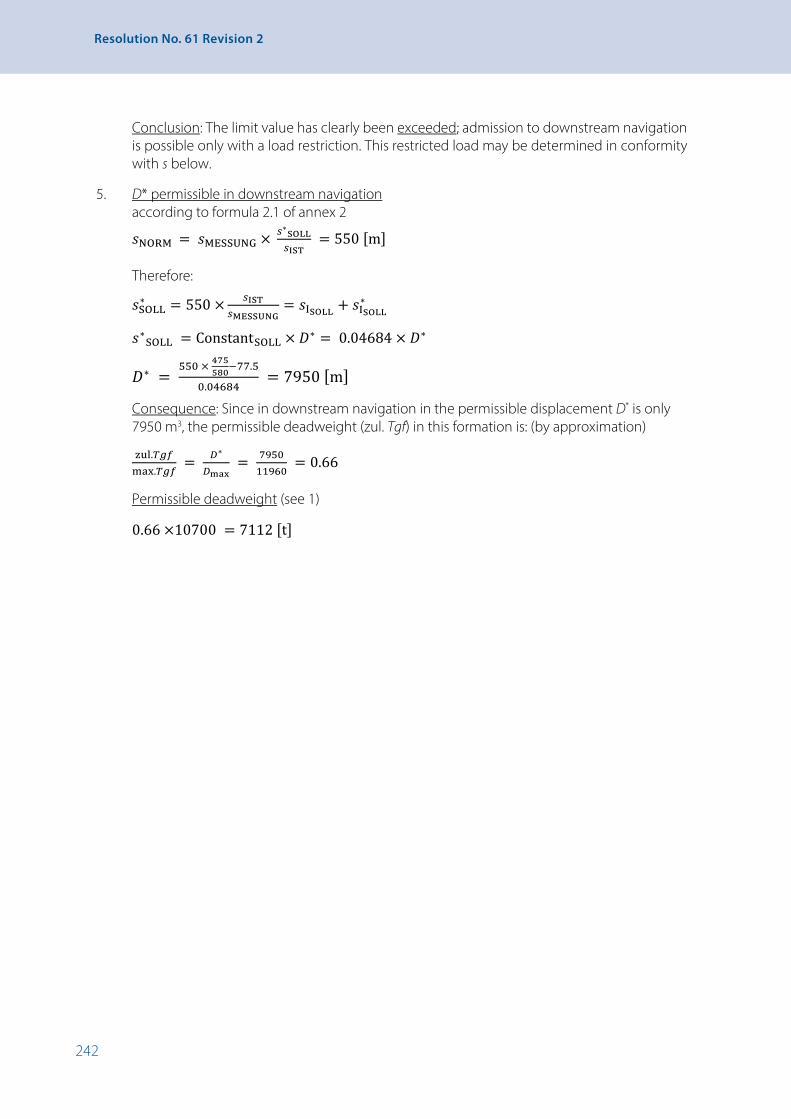
242
Resolution No. 61 Revision 2
Conclusion: The limit value has clearly been exceeded; admission to downstream navigation is possible only with a load restriction. This restricted load may be determined in conformity with s below.
5. D* permissible in downstream navigation according to formula 2.1 of annex 2
𝑠𝑠𝑠𝑠NORM = 𝑠𝑠𝑠𝑠MESSUNG × 𝑠𝑠𝑠𝑠∗SOLL𝑠𝑠𝑠𝑠IST
= 550 [m]
Therefore:
𝑠𝑠𝑠𝑠SOLL∗ = 550 × 𝑠𝑠𝑠𝑠IST𝑠𝑠𝑠𝑠MESSUNG
= 𝑠𝑠𝑠𝑠ISOLL + 𝑠𝑠𝑠𝑠ISOLL∗
𝑠𝑠𝑠𝑠∗SOLL = ConstantSOLL × 𝐷𝐷𝐷𝐷∗ = 0.04684 × 𝐷𝐷𝐷𝐷∗
𝐷𝐷𝐷𝐷∗ = 550 × 475580−77.5
0.04684 = 7950 [m]
Consequence: Since in downstream navigation in the permissible displacement D* is only 7950 m3, the permissible deadweight (zul. Tgf) in this formation is: (by approximation)
zul.𝑇𝑇𝑇𝑇𝑔𝑔𝑔𝑔𝑇𝑇𝑇𝑇max.𝑇𝑇𝑇𝑇𝑔𝑔𝑔𝑔𝑇𝑇𝑇𝑇
= 𝐷𝐷𝐷𝐷∗
𝐷𝐷𝐷𝐷max = 7950
11960 = 0.66
Permissible deadweight (see 1)
0.66 ×10700 = 7112 [t]

243
APPENDIX 4 - Alternative Manoeuvrability Test Procedures and Criteria in Accordance with 5-2.1
ADDENDUM 4-2 - Rules for the Classification and Construction of Inland Navigation Vessels of the Russian River Register
15 Manoeuvrability
15.1 Applicability
15.1.1 This section sets out manoeuvrability requirements for displacement vessels, which apply to:
1. Self-propelled cargo vessels that are 40 metres long or more;
2. Displacement passenger vessels, vessels intended to carry no more than 12 passengers and specialpurpose vessels that are 20 metres long or more.
15.1.2 The requirements in this section do not apply to pushed convoys, vessels in formation, catamarans or vessels with water-jet or cycloidal propellers or paddle wheels.
15.2 Definitions and explanations
15.2.1 The terms used in this section should be understood as follows:
1. Propulsion and steering system – the propeller and its steering devices (rudders and/or nozzles);
2. Vessel propulsion and steering system – all the propulsion and steering systems that are present on the vessel and ensure its longitudinal movement and manoeuvrability;
3. Turning capacity – the vessel’s ability to turn within a fairly small radius of curvature;
4. Directional stability – the vessel’s ability to maintain the chosen straight course in deep still water;
5. Manoeuvrability under wind conditions – the vessel’s ability to:
• Maintain any chosen straight course while all propellers are rotating at rated speed and the wind velocity in the navigational zone does not exceed that indicated in 15.9.2;
• Turn on the spot in the chosen direction under wind conditions by simultaneously operating the main controls and the bow steering device;
6. Manoeuvrability with propellers not in operation – the vessel’s ability to mechanically maintain a straight course under its own momentum, to turn in the chosen direction and to invert the direction of the turn;
7. Emergency stopping – quickly changing the operating mode of all the propellers from full speed ahead to full speed astern in deep still water, when loaded as indicated in 15.3.2.
15.3 General instructions for setting manoeuvrability standards
15.3.1 A vessel is considered to meet the manoeuvrability requirements set out in this section if, when loaded in accordance with 15.3.2, it satisfies the following criteria:
1. Turning capacity (see 15.5);
2. Directional stability (see 15.6);
3. Manoeuvrability with propellers not in operation (see 15.7);
4. Emergency stopping (see 15.8);
5. Manoeuvrability under wind conditions (see 15.9).

244
Resolution No. 61 Revision 2
15.3.2 The manoeuvrability test shall be conducted when the vessel is fully loaded, with an evenkeel trim, and fully stocked and refuelled.
Manoeuvrability tests for cargo vessels under wind conditions in accordance with 15.9.2.1 shall be conducted only for vessels in ballast, without cargo, and with 10 % of stock and fuel.
Manoeuvrability tests for passenger vessels under wind conditions in accordance with 15.9.2.1 shall be conducted only for vessels without cargo or passengers, and with 10 % of stock and fuel.
15.3.3 The vessel manoeuvrability criteria set out in this section apply to vessels with the following types of propulsion and steering systems:
1. Screw propellers in steering nozzles;
2. Screw propellers in steering nozzles with a centre rudder;
3. Rudders behind uncovered screw propellers;
4. Rudders behind nozzle propellers.
Manoeuvrability criteria values for vessels with the propulsion and steering systems listed are calculated in accordance with the instructions set out in the “Manual for calculating manoeuvrability and conducting fullscale manoeuvrability tests on inland and combined navigation vessels” (hereinafter referred to as the Manual).
15.3.4 Other well-founded methods can be used to determine manoeuvrability criteria for vessels with the propulsion and steering system types indicated in 15.3.3; the calculation performed in accordance with the Manual shall be submitted to the River Register at the same time.
15.3.5 Methods of determining manoeuvrability criteria for vessels with propulsion and steering system types not indicated in 15.3.3 shall be the subject of special consideration by the River Register.
15.3.6 Criteria for assessing a vessel’s turning capacity, directional stability and manoeuvrability with propellers not in operation can also be determined by:
1. Testing an autonomous selfpropelled vessel model which is geometrically similar to the vessel;
2. Conducting full-scale tests in accordance with the Manual.
In these cases, criteria values do not have to be calculated.
15.4 Table of manoeuvrability characteristics
15.4.1 To facilitate speedy reference, a table of each vessel’s manoeuvrability characteristics shall be posted in a visible place in the wheelhouse.
15.4.2 The table shall be drawn up by the organization responsible for the design of the vessel, and the results of the calculations shall be supplemented or corrected on the basis of data from fullscale tests and tests with selfpropelled models.
15.4.3 The form of the table is given in the Manual.
15.5 Turning capacity
15.5.1 In these Rules, the criterion for measuring turning capacity is the minimum relative mean steady-turning diameter (Dt /L)min, measured from the centre of gravity, that is, the ratio between the diameter Dt of the smallest possible turn which the vessel can make in deep still water and the length L of the vessel at the design waterline DWL, where the speed of rotation of all the propeller screws is the same prior to the commencement of the manoeuvre and is not subsequently regulated.

245
APPENDIX 4 - Alternative Manoeuvrability Test Procedures and Criteria in Accordance with 5-2.1
15.5.2 The vessel’s turning capacity is considered to satisfy the requirements set out in the Rules if the relative steady-turning diameter satisfies the condition
(Dt /L)min ≤ 2. (15.5.2)
15.6 Directional stability
15.6.1 In these Rules, the criterion for measuring directional stability is the minimum relative mean steady-turning diameter, measured from the centre of gravity, which the vessel makes in deep still water with the rudder angle at zero and all propeller screws rotating at the same speed.
15.6.2 The vessel’s directional stability is considered to satisfy the requirements set out in the Rules if the steady-turning diameter is 10 or more times the vessel’s length, and also if the vessel continues to move on a straight course without turning, with the rudder angle at zero.
15.7 Manoeuvrability with propellers not in operation
15.7.1 The criterion for measuring manoeuvrability with propellers not in operation is the vessel’s capacity to come out of a steady turn, made with the rudder at a 20º angle, after the main propellers have stopped, without using the steering device.
15.7.2 The vessel is considered to satisfy the requirements set out in the Rules if it can be taken out of a steady turn, made with the rudder at a 20º angle, after the main propellers have stopped, by operating the main controls, without using the steering device.
15.8 Emergency stopping capacity
15.8.1 The criterion for measuring emergency stopping capacity is the vessel’s stopping course SAT – the distance, m, which the vessel travels relative to the water from the moment when the order to make an emergency stop is given to the moment when the vessel has come to a complete stop relative to the water.
15.8.2 The vessel is considered to satisfy the requirements set out in this section if the stopping course SAT, m, satisfies the condition
SAT = 30.7 × 3√V + 1.28 × L, (15.8.2)
where V is the water displacement of the vessel, [m3];
L is the length of the vessel, [m].
15.9 Manoeuvrability under wind conditions
15.9.1 The criteria for measuring manoeuvrability under wind conditions are:
1. Wind velocity in navigational zone, m/s, which allows the vessel to move along any chosen straight course with all propellers rotating at the rated speed;
2. The specific thrust of the steering device, kN/m2, required for the vessel to turn on the spot using the main controls and the steering device.
The specific thrust of the steering device of a cargo vessel is the ratio TE /(L × T) between the thrust of the steering device TE , kN, and the product of the length of the vessel L at DWL and the full-load draught T. The specific thrust of the steering device of a passenger vessel is the ratio TE /S between the thrust of the steering device TE , kN, and the sail area S, m2.
15.8.2 The vessel is considered to satisfy the requirements set out in this section if the stopping course SAT, m, satisfies the condition
𝑆𝑆𝑆𝑆AT = 30.7 × √𝑉𝑉𝑉𝑉3 + 1.28 × 𝐿𝐿𝐿𝐿, (15.8.2)
Where V is the water displacement of the vessel, [m3]; L is the length of the vessel, [m].

246
Resolution No. 61 Revision 2
15.9.2 The vessel’s manoeuvrability under wind conditions is considered to satisfy the requirements set out in 15.9.1.1 if the wind velocity in the navigational zone which still allows the vessel to move on any chosen straight course with all the propellers rotating at rated speed is:
For “M” and “O” class vessels – no less than 19 m/s;
For “P” and “Л” class vessels – no less than 14 m/s.43
15.9.3 The requirement set out in 15.9.1.2 shall be met by installing a bow steering device on the vessel with a specific thrust of no less than the following:
For cargo vessels:
TE / (L × T) = 0.03; (15.9.3-1)
For passenger vessels with S × L ≥ 20,000 m3:
TE /S = 0.04 (15.9.3-2)
15.10 Full-scale tests
15.10.1 Full-scale tests designed to determine whether the vessel’s manoeuvrability is in compliance with the requirements set out in the Rules, as well as additions and corrections to the table of the vessel’s manoeuvrability characteristics, must be effected together with acceptance tests:
1. On the prototypes of series-built vessels;
2. On individually built vessels;
3. On vessels that have been repaired, re-equipped or modernized, if this can alter their manoeuvrability.
15.10.2 Full-scale tests must be carried out in accordance with 15.3.2. Deviations with regard to draught must not exceed 10 %.
15.10.3 Full-scale manoeuvrability tests on location shall be conducted in deep still water (the depth of the water in the test area must be no less than three times the draught of the vessel), with waves no greater than force 1-244 and wind velocity no greater than 3-4 m/s.
15.10.4 Full-scale manoeuvrability tests on location shall be conducted using the programme drawn up on the basis of the instructions set out in the Manual and in the Technical Regulations for Supervising over the Construction of Vessel and Manufacturing of Materials and Articles (PTNP).
43 Chapter 1 of these Recommendations provides that in the Russian Federation, navigational zones 1, 2 and 3 correspond to zones O, P and Л, respectively. Zone M covers waters where wave height can reach 3 m.
44 According to the scale of the Central Hydrometeorological Department of the Russian Federation.

247
APPENDIX 4 - Alternative Manoeuvrability Test Procedures and Criteria in Accordance with 5-2.1
ADDENDUM 4-3 - Recommendations of the Danube Commission concerning the Technical and Navigational Characteristics of Pushed Convoys
I. Introduction
The present recommendations, which specify technical and navigational requirements for pushed convoys, contribute to increasing navigational safety and to creating favourable conditions for the development of push-towing. They generalize the experience acquired by the Danube countries in that domain on which the uniform, minimum standards stemming from the need to ensure navigational safety are based.
II. General provisions
2.1 Objectives and scope
The purpose of these recommendations is to define the technical and navigational characteristics of pushed convoys.
These recommendations shall apply on the Danube to all pushed-convoy vessels that will be built after the entry into force of the recommendations.
2.2 Terms and definitions
The terms used in these recommendations are fully in accordance with the terms and definitions contained in the Basic Provisions relating to Navigation on the Danube (DFND) and other documents adopted by the Danube Commission.
2.3 Relations with documents in force and the DFND
The provisions of these recommendations are fully in accordance with the DFND and the local rules established by the Danube States and special river administrations and with other documents in force in the domain of push-towing. The provisions of these recommendations derive from those of the above-mentioned documents and contribute to their uniform application.
III. Technical and navigational standards for pushed convoys The pusher shall always be sufficiently powerful and manoeuvrable to ensure safe upstream and
downstream navigation for the pushed convoy; the technical and navigational characteristics of the pusher shall not be such as to hinder the movement of other vessels, in particular when passing through difficult sections (bends, shoals, bridges), and when overtaking, crossing or stopping.
3.1 Minimum speed
The pusher shall be able to maintain the convoy at a minimum speed of not less than 12 km/h in still water.
This condition is not required for pushers operating only in ports and roads.
3.2 Stopping distance and stopping time
The pusher shall be sufficiently powerful to bring the pushed convoy to a complete stop relative to the shore under the following conditions:
The distance travelled before stopping shall not exceed:
• Upstream: 200 m or one convoy length;
• Downstream: 600 m or three convoy lengths.
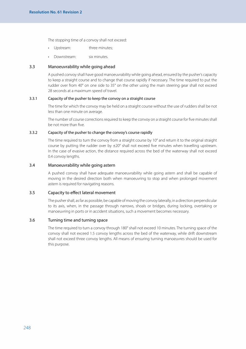
248
Resolution No. 61 Revision 2
The stopping time of a convoy shall not exceed:
• Upstream: three minutes;
• Downstream: six minutes.
3.3 Manoeuvrability while going ahead
A pushed convoy shall have good manoeuvrability while going ahead, ensured by the pusher’s capacity to keep a straight course and to change that course rapidly if necessary. The time required to put the rudder over from 40° on one side to 35° on the other using the main steering gear shall not exceed 28 seconds at a maximum speed of travel.
3.3.1 Capacity of the pusher to keep the convoy on a straight course
The time for which the convoy may be held on a straight course without the use of rudders shall be not less than one minute on average.
The number of course corrections required to keep the convoy on a straight course for five minutes shall be not more than five.
3.3.2 Capacity of the pusher to change the convoy’s course rapidly
The time required to turn the convoy from a straight course by 10° and return it to the original straight course by putting the rudder over by ±20° shall not exceed five minutes when travelling upstream. In the case of evasive action, the distance required across the bed of the waterway shall not exceed 0.4 convoy lengths.
3.4 Manoeuvrability while going astern
A pushed convoy shall have adequate manoeuvrability while going astern and shall be capable of moving in the desired direction both when manoeuvring to stop and when prolonged movement astern is required for navigating reasons.
3.5 Capacity to effect lateral movement
The pusher shall, as far as possible, be capable of moving the convoy laterally, in a direction perpendicular to its axis, when, in the passage through narrows, shoals or bridges, during locking, overtaking or manoeuvring in ports or in accident situations, such a movement becomes necessary.
3.6 Turning time and turning space
The time required to turn a convoy through 180° shall not exceed 10 minutes. The turning space of the convoy shall not exceed 1.5 convoy lengths across the bed of the waterway, while drift downstream shall not exceed three convoy lengths. All means of ensuring turning manoeuvres should be used for this purpose.

249
APPENDIX 4 - Alternative Manoeuvrability Test Procedures and Criteria in Accordance with 5-2.1
Methods for testing pushed convoys
These methods of conducting tests and measurements to determine the technical and navigational characteristics of pushed convoys contained in part III of the outline for the recommendations on the subject, are designed to establish uniform principles for full-scale testing of pushed convoys.
Prior to testing, basic data relating to the pushed convoys and navigating conditions in the test area need to be determined.
During testing, a minimum of two sets of measurements of the parameters in question shall be taken, and the average value for each characteristic calculated. The analysis of the results obtained for each characteristic shall be based on the conclusions of the tests and the final values for the specific pushed convoy or standard convoy can thus be determined.
A. Basic data on navigating conditions in the test area
Full-scale tests shall be carried out on a straight section of the river where the flow is uniform and there is sufficient channel width and depth. Testing shall be conducted as far as possible, in calm weather or with wind speed not exceeding force two on the Beaufort scale.
The bank of the test area shall be equipped with intersection markers and, as far as possible, with range markers or buoys fitted with radar reflectors. The intersection markers shall be placed at specified distances from each other.
The characteristics of the navigating conditions at the test area shall include:
• Location of the section (from km … to km …) and its length;
• Date (day, month, year) and time of the test;
• Weather conditions, visibility, wind speed and direction;
• Water level at the nearest measuring post;
• Average speed of current;
• Average channel width;
• Average channel depth.
B. Basic data on pushed convoys
Full-scale tests shall be carried out, as far as possible, with pushed convoys of maximum size navigating on the sector in question; the maximum dimensions shall be determined on the basis of practical experience, in the light of navigating conditions and the power and manoeuvrability of the pusher, while observing the conditions for navigational safety. On sections where regulations govern the dimensions of pushed convoys, the size of the pushed convoy shall not exceed the prescribed maximum. The formation of the convoy, the number of units and the amount of the cargo to be carried should be chosen according to whether the direction of navigation is upstream or downstream.
Pushed convoy vessels being tested shall as far as possible be of the same type and of identical draught.
The characteristics of a pushed convoy are determined by the following:
• Configuration of the pushed convoy;
• Size of the pushed convoy (Lmax , Bmax);
• Displacement, deadweight of the pushed convoy and amount of cargo carried;
• Data on the pushed vessels (Lmax , Bmax , Tmean.eff , Deff , Q);
• Data on the pusher (Lmax , Bmax , Tmax , N).

250
Resolution No. 61 Revision 2
C. Methods for testing the various technical and navigational characteristics of pushed convoys
The distance and position of a pushed convoy during testing may be measured by means of range markers installed on the bank or by radar photography, whereby the images on the radar screen of the pusher are photographed at specific time intervals, or by any other means ensuring an accuracy of measurement of ±10 m.
1. Speed
The speed of pushed convoys shall be measured moving both upstream and downstream, taking the following into account:
(a) Preparation for testing:
• The length of the section to be navigated shall be, as far as possible, not less than 2 km;
• Before measurements are taken, the pushed convoy shall travel a distance of one kilometre with the pusher’s engines at full power;
• When the pusher’s rudders are put over during testing, the deflection of the rudder blade shall not exceed ±5°.
(b) Values to be measured:
• Distance travelled;
• Time required to travel this distance;
• Revolutions of the main machinery.
(c) Data to be calculated:
• Speed of movement upstream relative to the bank;
• Speed of movement upstream relative to the water;
• Speed of movement downstream relative to the bank;
• Speed of movement downstream relative to the water.
The measurements of speed shall be used to determine the minimum speed of a pushed convoy relative to the bank in km/h which meets the conditions for safety of navigation even when passing through sections of the channel which are difficult to navigate.
2. Stopping distance and stopping time
These values shall be measured for convoys moving both upstream and downstream.
(a) Preparation for testing:
• Before testing begins, the pushed convoy shall travel a distance of one kilometre with the pusher’s engines at full power;
• When the pusher’s rudders are put over during testing, the deflection of the rudder blade shall not exceed ±5°;
(b) Values to be measured:
• Revolutions of the main machinery;

251
APPENDIX 4 - Alternative Manoeuvrability Test Procedures and Criteria in Accordance with 5-2.1
• Speed relative to the bank at the beginning of the tests;
• Time required:
• To stop the engines when going full speed ahead;
• To reverse the engines;
• To put the engines into full speed astern;
• Time required for the engines running at full speed astern to bring the convoy to a stop relative to the bank;
• Distance travelled relative to the bank, measured in periods of time, before the convoy is brought to a stop.
(c) Values to be calculated:
• Total distance travelled before stopping relative to the bank when navigating upstream;
• Total time required to stop the convoy relative to the bank when navigating upstream;
• Total distance travelled before stopping relative to the bank when navigating downstream;
• Total time required to stop the convoy relative to the bank when navigating downstream.
3. Manoeuvrability while going ahead
The evaluation of manoeuvrability while going ahead at full speed (100 % of the rated power of the main machinery), at medium speed (50 % of the rated power) and at low speed (25 % of the rated power), when navigating upstream and downstream shall consist in determining the ability of the pusher to keep the convoy on a straight course with minimum use of rudders, and its ability to change the convoy’s course rapidly.
(a) Ability of the pusher to keep the convoy on a straight course
This ability shall be measured at full, medium and low speed upstream and downstream, and consists in the measurement of the following values:
• Average time that a chosen course can be maintained without the use of rudders;
• Number of turns of the rudder required to keep the convoy on the course specified and the average helm value over a period of five minutes.
(b) Ability of the pusher to change the convoy’s course rapidly
This ability shall be measured at full and medium speed upstream, and consists in the measurement of the following values:
• Time required to turn the convoy from its course by 10° by putting the rudder over 20°;
• Time required to return the convoy to its original course and turn it from that course by 10° in the opposite direction by putting the rudder over 20° on the opposite side;
• Time required to return the convoy to its original course by putting the rudder over up to ±20°;
• Distance covered, by periods of time;
• Lateral movement of the convoy from the original straight course.

252
Resolution No. 61 Revision 2
While navigating downstream, the above measurements shall be taken in the same way, except that the rudder shall be put over in varying positions of up to 20°, 30° and 40°.
The following may be determined from the measurements:
• The time required to turn the convoy by 10°, to turn it back, to turn it by 10° to the opposite side and to return the convoy to its original course;
• The distance travelled and the maximum lateral movement of the convoy while changing course.
4. Manoeuvrability while going astern
Manoeuvrability while going astern, upstream and downstream, shall be ensured by:
• The reverse rudders, or
• The forward and reverse rudders, or
• The rudders and engines.
Measurements of manoeuvrability while going astern are taken in the same way as those of manoeuvrability while going ahead, keeping in mind the maintenance of the chosen course and the ability to return to the original course after a turn; the difference between the tests lies in the fact that for the measurement of the manoeuvrability while going astern, the rudders may be put over to any position and the engines used.
On the basis of the analysis of the test results, the time for which the pushed convoy can maintain manoeuvrability while going astern by putting over the rudders and using the engines shall be determined.
5. Turning time and turning space
Turning ability shall be tested with pushed convoys in formation for upstream and downstream navigation by the following manoeuvres:
• 180° turn downstream;
• 180° turn upstream.
When turning manoeuvres are effected, any position of the pusher’s rudders, any speed and any mode of operation of the main machinery as well as the use of the bow rudder are permitted in order to turn as tightly as possible. The method of effecting this manoeuvre (position of the rudders, direction of the engines) shall be indicated for each kind of turn, and the following measurements shall be taken:
• Speed relative to the bank before the tests;
• Time required to turn through 180°;
• Width of turning space, measured perpendicularly to the direction of the current;
• Length of turning space, measured according to the direction of the current.
On the basis of the analysis of the test results, the following data shall be determined for the different cases:
• Time required to turn through 180°;
• Ratio of the width of the turning space to the length of the pushed convoy B0 / L = …;
• Ratio of the length of the turning space to the length of the pushed convoy B0 / L = … .

253
APPENDIX 5 - Model of a Service Record
APPENDIX 5 - Model of a Service Record
Model of a Service Record
– 1 – A-00735

254
Resolution No. 61 Revision 2
SERVICE RECORD
issued by:
Holder:
............................................................................................................................................................................. Name: ............................................................................................................................................................ First name(s): ............................................................................................................................................. Born on: .................................................................................................................................................................. Photograph of holder Born at: ........................................................................................................................................................................................................... Nationality: .................................................................................................................................................................................................. The holder of this Service Record has given the following proof of identity:
passport
national identity card
the document referred to below, with its official translation:
Description of the document: .....................................................................................................................
No. of the document: ........................................................................................................................................
Document issued by: ........................................................................................................................................
Place, date, stamp and signature of the authority issuing the service record
- 2 -
– 2 – A-00735
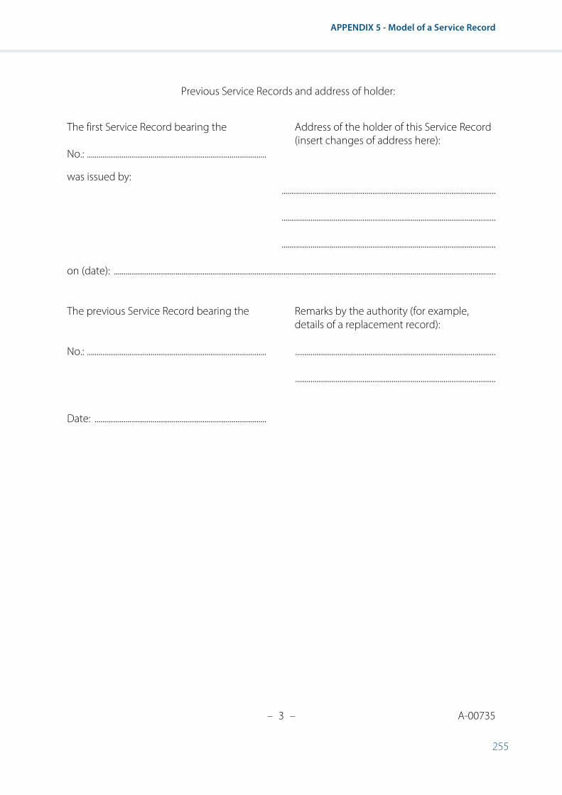
255
APPENDIX 5 - Model of a Service Record
– 3 – A-00735
Previous Service Records and address of holder: The first Service Record bearing the Address of the holder of this Service Record (insert changes of address here): No.: .............................................................................................
was issued by: ............................................................................................................... ............................................................................................................... ...............................................................................................................
on (date): ...................................................................................................................................................................................................... The previous Service Record bearing the Remarks by the authority (for example, details of a replacement record): No.: ............................................................................................. ........................................................................................................ ........................................................................................................ Date: .........................................................................................
- 3 -

256
Resolution No. 61 Revision 2
HOLDER’S QUALIFICATIONS IN ACCORDANCE WITH SECTION 23-2 OF CHAPTER 23 “CREWS”
Qualification: ....................................................................... Qualification: ............................................................................... as from (date) as from (date) Stamp, date and signature of the authority: Stamp, date and signature of the authority: Qualification: ....................................................................... Qualification: ............................................................................... as from (date) as from (date) Stamp, date and signature of the authority: Stamp, date and signature of the authority: Qualification: ....................................................................... Qualification: ............................................................................... as from (date) as from (date) Stamp, date and signature of the authority: Stamp, date and signature of the authority:
- 4 -
– 4 – A-00735

257
APPENDIX 5 - Model of a Service Record
– 5 – A-00735
CERTIFICATE OF FITNESS IN ACCORDANCE WITH SECTION 23-3 OF CHAPTER 23 “CREWS”
The holder of this Service Record qualifies on the basis of the medical certificate referred to in paragraph 19-3.1 of the above-mentioned chapter issued by: ...................................................................................................................................................................................................... issued on: .....................................................................................................................................................................................................
□ fit ............................................................................................................................................................................................
□ limited fitness ................................................................................................................................................................ subject to the following condition(s): ............................................................................................................................................................................................................ ............................................................................................................................................................................................................ ............................................................................................................................................................................................................ Period of validity: .....................................................................................................................................................................................
- 5 -

258
Resolution No. 61 Revision 2
SAILING TIME ON BOARD, NAME OF VESSEL: Official number of vessel: ..................................................................................................................................................................
Type of vessel: ...........................................................................................................................................................................................
Flag: ..................................................................................................................................................................................................................
Length of vessel in m,* number of passengers: .................................................................................................................
Owner (name, address): .....................................................................................................................................................................
Entry on duty of holder with the position of: ......................................................................................................................
Entry on duty on (date): .....................................................................................................................................................................
Until (date): .................................................................................................................................................................................................
Boatmaster (name, address): ...........................................................................................................................................................
.............................................................................................................................................................................................................................................................................
Place, date and signature of boatmaster: ...............................................................................................................................
..............................................................................................................................................................................................................................
..............................................................................................................................................................................................................................
Sailing time on board, name of vessel: ....................................................................................................................................
Official number of vessel: ..................................................................................................................................................................
Type of vessel: ...........................................................................................................................................................................................
Flag: ..................................................................................................................................................................................................................
Length of vessel in m,* number of passengers: .................................................................................................................
Owner (name, address): .....................................................................................................................................................................
.............................................................................................................................................................................................................................................................................
Entry on duty of holder with the position of: ......................................................................................................................
Entry on duty on (date): .....................................................................................................................................................................
Until (date): .................................................................................................................................................................................................
Boatmaster (name, address): ...........................................................................................................................................................
.............................................................................................................................................................................................................................................................................
Place, date and signature of boatmaster: ...............................................................................................................................
___________________
* Delete as appropriate
– 6 – A-00735

259
APPENDIX 5 - Model of a Service Record
– 7 – A-00735
Pages 7–23 are identical to page 6.

260
Resolution No. 61 Revision 2
–
24 –
A-
0073
5
SAIL
ING
TIM
ES A
ND
SEC
TORS
CO
VER
ED D
URI
NG
TH
E YE
AR
Saili
ng ti
mes
mus
t cor
resp
ond
to th
e en
trie
s in
the
log!
Nam
e of
ves
sel
or re
gist
rati
on n
umbe
r of
ves
sel
Voya
ge fr
om ..
......
via
.....
... to
...
......
(k
.p.)
(k
.p.)
Star
t of
voya
ge
(Dat
e)
Day
s in
terr
upte
d
End
of v
oyag
e (D
ate)
Num
ber o
f day
s
of v
oyag
e
Sign
atur
e
of b
oatm
aste
r
AB
CD
EF
G
1 2 3 Entr
y by
the
auth
orit
y: to
tal d
ays
of v
oyag
e ta
ken
into
acc
ount
on
this
pag
e
Co
ntro
l sta
mp
Pr
esen
ted
on (d
ate)
......
........
........
........
........
........
........
........
........
........
........
........
........
........
........
........
Sign
atur
e an
d st
amp
of th
e au
thor
ity
Doc
umen
t com
plet
e ❏
ye
s
❏
no
❏
do
ubts
aris
ing
from
the
pres
enta
tion
of th
e lo
g (e
xtra
cts)
❏
doub
ts in
line
(s) .
........
........
........
........
........
........
........
... ❏
do
ubts
aris
ing
from
the
pres
enta
tion
of a
ny o
ther
app
ropr
iate
doc
umen
tary
evi
denc
e
The
head
ings
of c
olum
ns A
to G
are
not
repe
ated
on
the
next
30
page
s.
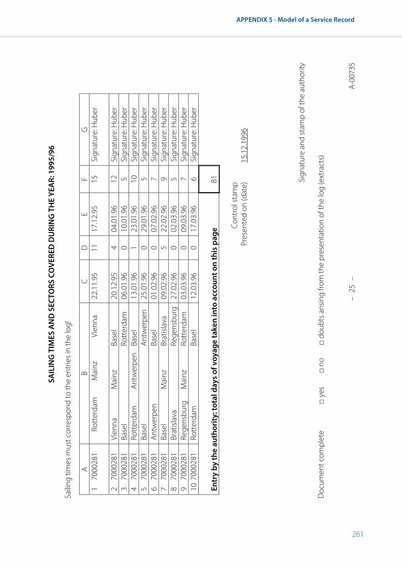
261
APPENDIX 5 - Model of a Service Record
SAIL
ING
TIM
ES A
ND
SEC
TORS
CO
VERE
D D
URI
NG
TH
E YE
AR:
199
5/96
Saili
ng ti
mes
mus
t cor
resp
ond
to th
e en
trie
s in
the
log!
A B
C D
E
F G
1
7000
281
Rott
erda
m
Mai
nz
Vien
na
22.1
1.95
11
17
.12.
95
15
Sign
atur
e: H
uber
2 70
0028
1 Vi
enna
M
ainz
Ba
sel
20.1
2.95
4
04.0
1.96
12
Si
gnat
ure:
Hub
er
3 70
0028
1 Ba
sel
Rott
erda
m
06.0
1.96
0
10.0
1.96
5
Sign
atur
e: H
uber
4
7000
281
Rott
erda
m
Antw
erpe
n Ba
sel
13.0
1.96
1
23.0
1.96
10
Si
gnat
ure:
Hub
er
5 70
0028
1 Ba
sel
Antw
erpe
n 25
.01.
96
0 29
.01.
96
5 Si
gnat
ure:
Hub
er
6 70
0028
1 An
twer
pen
Base
l 01
.02.
96
0 07
.02.
96
7 Si
gnat
ure:
Hub
er
7 70
0028
1 Ba
sel
Mai
nz
Brat
islav
a 09
.02.
96
5 22
.02.
96
9 Si
gnat
ure:
Hub
er
8 70
0028
1 Br
atisl
ava
Rege
nsbu
rg
27.0
2.96
0
02.0
3.96
5
Sign
atur
e: H
uber
9
7000
281
Rege
nsbu
rg
Mai
nz
Rott
erda
m
03.0
3.96
0
09.0
3.96
7
Sign
atur
e: H
uber
10
700
0281
Ro
tter
dam
Ba
sel
12.0
3.96
0
17.0
3.96
6
Sign
atur
e: H
uber
En
try
by th
e au
thor
ity: t
otal
day
s of
voy
age
take
n in
to a
ccou
nt o
n th
is p
age
81
Co
ntro
l sta
mp
Pr
esen
ted
on (d
ate)
15
.12.
1996
Sign
atur
e an
d st
amp
of th
e au
thor
ity
Doc
umen
t com
plet
e □
yes
□ no
□
doub
ts a
risin
g fro
m th
e pr
esen
tatio
n of
the
log
(ext
ract
s)
–
25 –
A-
0073
5

262
Resolution No. 61 Revision 2
SAIL
ING
TIM
ES A
ND
SEC
TORS
CO
VERE
D D
URI
NG
TH
E YE
AR
Saili
ng ti
mes
mus
t cor
resp
ond
to th
e en
trie
s in
the
log!
A B
C D
E
F G
1
2
3
4
5
6
7
8
9
10
Entr
y by
the
auth
ority
: tot
al d
ays
of v
oyag
e ta
ken
into
acc
ount
on
this
pag
e
Co
ntro
l sta
mp
Pr
esen
ted
on (d
ate)
......
........
........
........
........
........
........
........
........
........
........
..
Sign
atur
e an
d st
amp
of th
e au
thor
ity
Doc
umen
t com
plet
e □
yes
□ no
□
doub
ts a
risin
g fro
m th
e pr
esen
tatio
n of
the
log
(ext
ract
s)
□ do
ubts
in li
ne(s
) □
doub
ts in
line
(s) o
f any
oth
er a
ppro
pria
te d
ocum
enta
ry e
vide
nce
–
26 –
A-
0073
5

263
APPENDIX 5 - Model of a Service Record
Pages 27–55 are identical to page 26.
–
27 –
A-
0073
5
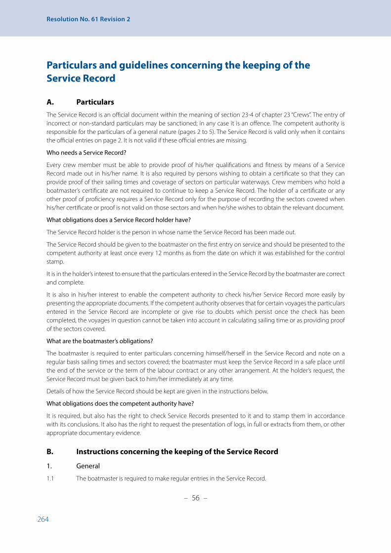
264
Resolution No. 61 Revision 2
Particulars and guidelines concerning the keeping of the Service Record
A. Particulars
The Service Record is an official document within the meaning of section 23-4 of chapter 23 “Crews”. The entry of incorrect or non-standard particulars may be sanctioned; in any case it is an offence. The competent authority is responsible for the particulars of a general nature (pages 2 to 5). The Service Record is valid only when it contains the official entries on page 2. It is not valid if these official entries are missing.
Who needs a Service Record?
Every crew member must be able to provide proof of his/her qualifications and fitness by means of a Service Record made out in his/her name. It is also required by persons wishing to obtain a certificate so that they can provide proof of their sailing times and coverage of sectors on particular waterways. Crew members who hold a boatmaster’s certificate are not required to continue to keep a Service Record. The holder of a certificate or any other proof of proficiency requires a Service Record only for the purpose of recording the sectors covered when his/her certificate or proof is not valid on those sectors and when he/she wishes to obtain the relevant document.
What obligations does a Service Record holder have?
The Service Record holder is the person in whose name the Service Record has been made out.
The Service Record should be given to the boatmaster on the first entry on service and should be presented to the competent authority at least once every 12 months as from the date on which it was established for the control stamp.
It is in the holder’s interest to ensure that the particulars entered in the Service Record by the boatmaster are correct and complete.
It is also in his/her interest to enable the competent authority to check his/her Service Record more easily by presenting the appropriate documents. If the competent authority observes that for certain voyages the particulars entered in the Service Record are incomplete or give rise to doubts which persist once the check has been completed, the voyages in question cannot be taken into account in calculating sailing time or as providing proof of the sectors covered.
What are the boatmaster’s obligations?
The boatmaster is required to enter particulars concerning himself/herself in the Service Record and note on a regular basis sailing times and sectors covered; the boatmaster must keep the Service Record in a safe place until the end of the service or the term of the labour contract or any other arrangement. At the holder’s request, the Service Record must be given back to him/her immediately at any time.
Details of how the Service Record should be kept are given in the instructions below.
What obligations does the competent authority have?
It is required, but also has the right to check Service Records presented to it and to stamp them in accordance with its conclusions. It also has the right to request the presentation of logs, in full or extracts from them, or other appropriate documentary evidence.
B. Instructions concerning the keeping of the Service Record
1. General
1.1 The boatmaster is required to make regular entries in the Service Record.
– 56 –
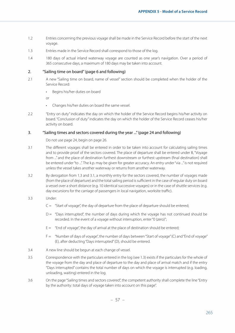
265
APPENDIX 5 - Model of a Service Record
1.2 Entries concerning the previous voyage shall be made in the Service Record before the start of the next voyage.
1.3 Entries made in the Service Record shall correspond to those of the log.
1.4 180 days of actual inland waterway voyage are counted as one year’s navigation. Over a period of 365 consecutive days, a maximum of 180 days may be taken into account.
2. “Sailing time on board” (page 6 and following)
2.1 A new “Sailing time on board, name of vessel” section should be completed when the holder of the Service Record:
• Begins his/her duties on board
or
• Changes his/her duties on board the same vessel.
2.2 “Entry on duty” indicates the day on which the holder of the Service Record begins his/her activity on board. “Conclusion of duty” indicates the day on which the holder of the Service Record ceases his/her activity on board.
3. “Sailing times and sectors covered during the year ...” (page 24 and following)
Do not use page 24, begin on page 26.
3.1 The different voyages shall be entered in order to be taken into account for calculating sailing times and to provide proof of the sectors covered. The place of departure shall be entered under B, “Voyage from ...” and the place of destination furthest downstream or furthest upstream (final destination) shall be entered under “to ...”. The k.p. may be given for greater accuracy. An entry under “via ...” is not required unless the vessel takes another waterway or returns from another waterway.
3.2 By derogation from 1.3 and 3.1, a monthly entry for the sectors covered, the number of voyages made (from the place of departure) and the total sailing period is sufficient in the case of regular duty on board a vessel over a short distance (e.g. 10 identical successive voyages) or in the case of shuttle services (e.g. day excursions for the carriage of passengers in local navigation, worksite traffic).
3.3 Under:
C = “Start of voyage”, the day of departure from the place of departure should be entered;
D = “Days interrupted”, the number of days during which the voyage has not continued should be recorded. In the event of a voyage without interruption, enter “0 (zero)”;
E = “End of voyage”, the day of arrival at the place of destination should be entered;
F = “Number of days of voyage”, the number of days between “Start of voyage” (C) and “End of voyage” (E), after deducting “Days interrupted” (D), should be entered.
3.4 A new line should be begun at each change of vessel.
3.5 Correspondence with the particulars entered in the log (see 1.3) exists if the particulars for the whole of the voyage from the day and place of departure to the day and place of arrival match and if the entry “Days interrupted” contains the total number of days on which the voyage is interrupted (e.g. loading, unloading, waiting) entered in the log.
3.6 On the page “Sailing times and sectors covered”, the competent authority shall complete the line “Entry by the authority: total days of voyage taken into account on this page”.
– 57 –
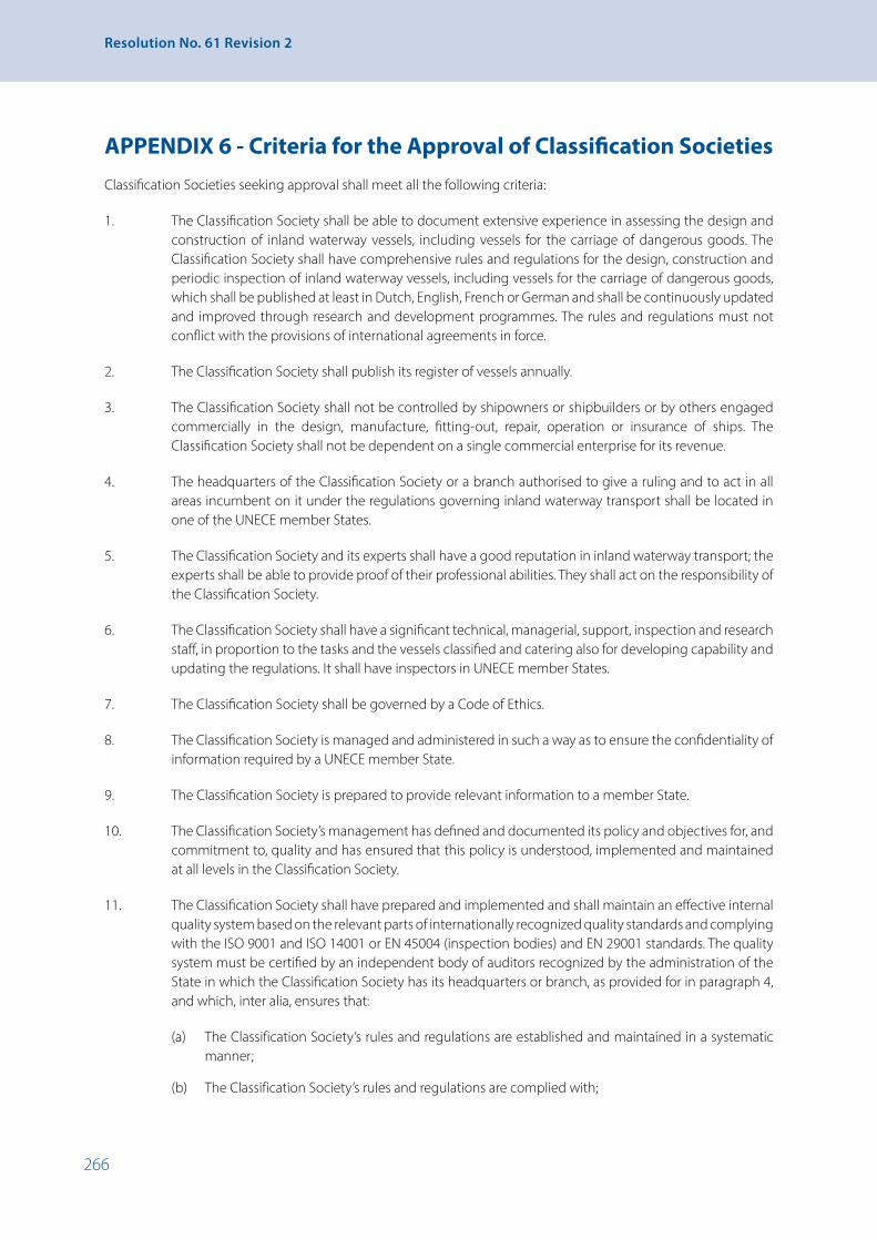
266
Resolution No. 61 Revision 2
APPENDIX 6 - Criteria for the Approval of Classification SocietiesClassification Societies seeking approval shall meet all the following criteria:
1. The Classification Society shall be able to document extensive experience in assessing the design and construction of inland waterway vessels, including vessels for the carriage of dangerous goods. The Classification Society shall have comprehensive rules and regulations for the design, construction and periodic inspection of inland waterway vessels, including vessels for the carriage of dangerous goods, which shall be published at least in Dutch, English, French or German and shall be continuously updated and improved through research and development programmes. The rules and regulations must not conflict with the provisions of international agreements in force.
2. The Classification Society shall publish its register of vessels annually.
3. The Classification Society shall not be controlled by shipowners or shipbuilders or by others engaged commercially in the design, manufacture, fitting-out, repair, operation or insurance of ships. The Classification Society shall not be dependent on a single commercial enterprise for its revenue.
4. The headquarters of the Classification Society or a branch authorised to give a ruling and to act in all areas incumbent on it under the regulations governing inland waterway transport shall be located in one of the UNECE member States.
5. The Classification Society and its experts shall have a good reputation in inland waterway transport; the experts shall be able to provide proof of their professional abilities. They shall act on the responsibility of the Classification Society.
6. The Classification Society shall have a significant technical, managerial, support, inspection and research staff, in proportion to the tasks and the vessels classified and catering also for developing capability and updating the regulations. It shall have inspectors in UNECE member States.
7. The Classification Society shall be governed by a Code of Ethics.
8. The Classification Society is managed and administered in such a way as to ensure the confidentiality of information required by a UNECE member State.
9. The Classification Society is prepared to provide relevant information to a member State.
10. The Classification Society’s management has defined and documented its policy and objectives for, and commitment to, quality and has ensured that this policy is understood, implemented and maintained at all levels in the Classification Society.
11. The Classification Society shall have prepared and implemented and shall maintain an effective internal quality system based on the relevant parts of internationally recognized quality standards and complying with the ISO 9001 and ISO 14001 or EN 45004 (inspection bodies) and EN 29001 standards. The quality system must be certified by an independent body of auditors recognized by the administration of the State in which the Classification Society has its headquarters or branch, as provided for in paragraph 4, and which, inter alia, ensures that:
(a) The Classification Society’s rules and regulations are established and maintained in a systematic manner;
(b) The Classification Society’s rules and regulations are complied with;

267
APPENDIX 6 - Criteria for the Approval of Classification Societies
(c) The requirements of the statutory work for which the Classification Society is authorized are satisfied;
(d) The responsibilities, authorities and interrelation of personnel whose work affects the quality of the Classification Society’s services are defined and documented;
(e) All work is carried out under controlled conditions;
(f ) a supervisory system is in place which monitors the actions and work carried out by surveyors and technical and administrative staff employed directly by the Classification Society;
(g) The requirements of major statutory work for which the Classification Society organization is authorized are only carried out or directly supervised by its exclusive surveyors or through exclusive surveyors of other recognized Classification Societies;
(h) A system for qualification of surveyors and continuous updating of their knowledge is implemented;
(i) Records are maintained, demonstrating achievement of the required standards in the items covered by the services performed, as well as the effective operation of the quality system; and
(j) A comprehensive system of planned and documented internal audits of the quality related activities in all locations.
12. The quality system must be certified by an independent body of auditors recognized by the administration of the State in which the Classification Society has its headquarters or branch, as provided for in section 4.

268
Resolution No. 61 Revision 2
APPENDIX 7 - Requirements Concerning Lights and the Colour of Signal Lights on Vessels, Intensity and Range of Signal Lights on Vessels and General Technical Specifications Applicable to Radar Equipment
I. Lights and the colour of signal lights on vessels45
A. General 1. Technical requirements
The construction of and materials of signal lanterns shall be such as to ensure their safety and durability.
The components of the lantern (for example the cross braces) shall not modify the intensity, colours or dispersion of the light.
It shall be possible to install the lights on board simply and in the correct position.
It shall be easy to replace the light source.
B. Colour of signal lights 1. A five colour signal system is applied to the lights, and comprises the following colours:
“white”
“red”
“green”
“yellow” and
“blue”.
This system conforms to the recommendations of the International Commission on Illumination, “Colours of Signal Lights”, IEC publication No. 2.2 (TC-1.6) 1975.
The colours apply to the light fluxes emitted by the lantern.
2. The colour boundaries of signal lights are demarcated by the coordinates (table 1) of the intersecting points of the chromatic diagram of IEC publication No. 2.2 (TC-1.6) 1975 (figure 1).
Table 1 Colour boundaries of signal lights
Colour of signal light Coordinates of the intersecting points
White x 0.310 0.443 0.500 0.500 0.453 0.310
y 0.283 0.382 0.382 0.440 0.440 0.348
Red x 0.690 0.710 0.680 0.660
y 0.290 0.290 0.320 0.320
Green x 0.009 0.284 0.207 0.013
y 0.720 0.520 0.397 0.494
Yellow x 0.612 0.618 0.575 0.575
y 0.382 0.382 0.425 0.406
Blue x 0.136 0.218 0.185 0.102
y 0.040 0.142 0.175 0.105
45 On the inland waterways of Belarus, Kazakhstan, Lithuania, Republic of Moldova, Russian Federation and Ukraine the colour of signal lights on vessels shall satisfy the requirements of the competent national authorities.

269
APPENDIX 7 - Requirements Concerning Lights and the Colour of Signal Lights on Vessels, Intensity and Range of Signal Lights on Vessels and General Technical Specifications Applicable to Radar Equipment
Figure 1 IEC chromaticity diagram
2360 K corresponds to the light of a vacuum filament lamp.
2848 K corresponds to the light of a gas-filled filament lamp.
0.8
0.7
0.6
0.5
0.4
0.3
0.2
0.1
00 0.1 0.2 0.3 0.4 0.5 0.6 0.7 0.8
X
Y
640650660680
690 - 780
YELLOW
WHITE
GREEN
BLUE
RED
480
460440
450430420
490
500
510
520
530
540
550
580
600
620
1900
2 000 4 000
10 000 E
X0
630
610
560
6 000
470
570
2 360 P2856 590
380 - 410
GREEN
WHITE
YELLOWW
RED

270
Resolution No. 61 Revision 2
II. Intensity and range of signal lights on vessels46
A. General
1. Signal lights
Signal lights are classified according to their luminous intensity as:
“Ordinary lights”
“Bright lights”
“Strong lights”.
2. Relation between IO, IB and t IO is the photometric luminous intensity,in [candela (cd)], measured at normal voltage for electric lights.
IB is the operation luminous intensity, in [candela (cd)].
t is the range, in [km].
Taking into account, for example, the ageing of the light source, the degree of dirtiness of the optic and variations in the voltage of the on-board grid, IB is 20 % less than IO.
Consequently, IB = 0.8 × IO.
The relation between IB and t of signal lights is given by the following equation:
IB = 0.2 × t2 × q-t.
The atmospheric transmission coefficient q has been taken as 0.76, corresponding to a meteorological visibility of 14.3 km.
B. Intensity and range47
1. Luminous intensity and visibility range of signal lights The following table contains the permitted limits for IO, IB and t according to the nature of signal lights.
The values indicated apply to the light flux emitted by the lantern.
IO and IB are given in cd and t – in nautical miles (nm) and kilometres (km).
Table 2 Minimum and maximum values
Nominal value of visibility range of
signal lights
Minimum value of visibility range (tmin)
Maximum value of
visibility range (tmax)
Operational luminous
intensity (IB)
Minimum horizontal
photometric luminous
intensity (IO)*
Maximum horizontal
photometric luminous
intensity (IO)*
Nature of signal lights
nm nm km nm km cd cd cd
1 1 1.85 2 3.70 0.9 1.1 5.4 Ordinary
2 2 3.70 5 9.26 4.3 5.4 65 Bright
3 3 5.56 5 9.26 12 15 65 Bright
5 5 9.26 7.5 13.90 52 65** 257 Strong
6 6 11.11 7.5 13.90 94 118** 257 Strong
* To be measured in the laboratory.** However, for daytime use of the strong yellow scintillating lights a minimum photometric luminous intensity IO of 900 cd shall apply.
46 On the inland waterways of Belarus, Kazakhstan, Lithuania, Republic of Moldova, Russian Federation and Ukraine, the luminous intensity and range of signal lights on vessels shall satisfy the requirements of the competent national authorities.
47 On certain inland waterways the competent authority may allow the carriage by vessels of signal lights in accordance with the requirements of the Convention on the International Regulations for Preventing Collisions at Sea (COLREG).

271
APPENDIX 7 - Requirements Concerning Lights and the Colour of Signal Lights on Vessels, Intensity and Range of Signal Lights on Vessels and General Technical Specifications Applicable to Radar Equipment
C. Signal light dispersion
1. Horizontal dispersion of intensity
(a) The luminous intensities indicated in section II apply to all directions of the horizontal plane passing through the focus of the optic or the luminous centre of gravity of the light source correctly adjusted within the operational sector of a vertically positioned lantern;
(b) For the masthead lights, stern lights and side lights, the luminous intensities prescribed shall be maintained throughout the horizontal arc within the sectors prescribed at least up to within 5° of the limits.
As from 5° within the sectors prescribed up to the limit, the luminous intensity may decrease by 50 %; it shall subsequently decrease gradually in such a way that, as from 5° beyond the limits of the sector, only a negligible amount of light remains;
(c) The side lights shall have the prescribed luminous intensity in the direction parallel to the axis of the vessel forward. The intensities shall decrease practically to zero between 1° and 3° beyond the limits of the prescribed sector;
(d) For bicoloured or tricoloured lanterns, the dispersion of the luminous intensity shall be uniform so that 3° on either side of the prescribed sector limits, the maximum permitted intensity is not exceeded and the minimum prescribed intensity is reached;
(e) The horizontal dispersion of the luminous intensity of the lanterns shall be uniform throughout the sector, so that the minimum and maximum values observed do not differ more than by a factor of 1.5 from the photometric luminous intensity.
2. Vertical dispersion of intensity
In the event of heeling of power driven vessels of up to ± 5° or ± 7.5° from the horizontal, the luminous intensity shall remain at least equal to 100 % in the first case, and 60 % in the second case, of the luminous intensity corresponding to 0° heeling, although it shall not exceed it by more than 1.2 times. In the event of heeling of sailing vessels of up to ± 5° or ± 25° from the horizontal, the luminous intensity shall remain at least equal to 100 % in the first case, and 50 % in the second case, of the luminous intensity corresponding to 0° heeling, although it shall not exceed it by more than 1.2 times.
III. General technical specifications applicable to radar equipment
1. The technical parameters of radar installations must satisfy the following requirements:
Minimum range of detection 15 mMaximum range of detection of shore 60 m high (at height of installation 10 m)
32,000 m48
Distance resolution 15 m at scales 0.5–1.6 km; 1 % of the scale value at other scales
Angular resolution 1.2°Accuracy of measurement: range 10 m for variable range circles; 1 % of fixed range
circles at scales 0.5–2.0 km; 0.8 % of the value of the selected scale.
Accuracy of measurement: bearings line: +1°Heading line:- Width - Deviation
0.5° 0.5°
Effective diameter of screen indicator 270 mm49
48 Maximum range of detection is only required to be ensured for radar equipment installed on vessels operated on large lakes, reservoirs and in coastal waters.
49 In the Russian Federation, effective diameter of screen indicator for vessels with gross tonnage from 300 to 1600 tonnes – not less than 180 mm.

272
Resolution No. 61 Revision 2
Range scales 0.5; 1; 1.6; 2; 3.2; 4; 8; 16; 32 km: not less than 4 fixed range circles within each scale
Off-centring 1/4–1/3 of the effective diameter of the imageBearing facilities: - Timing - Error
Up to 5 seconds +1°
Transmission frequency 9.3–9.5 GHz (3.2 cm)Warm-up time 4 minutesMinimum antenna speed 24 revolutions per minute
2. The requirements contained in IEC publication 945 “Marine Navigational Equipment General Requirements” shall apply to power supply, safety, mutual interference of shipborne equipment, compass safe distance, resistance to climatic influences, mechanical strength, environmental influences, audible noise emission and equipment markings of radar installations. Additionally, the requirements of the ITU Radio Regulations shall apply. The equipment shall satisfy all requirements of these provisions for radar display ambient temperatures between 0 and -55°C in doors and between -30 and +55°C on the open desk.
3. Controls of radar installations
3.1 All controls shall be so arranged that during their operation no information is concealed from view and radar navigation remains unimpaired.
3.2 Controls which can be used to switch off the equipment or, if activated, could lead to a malfunction must be protected against accidental operation.
3.3 The following functions must have their own controls with direct access:
(a) Stand-by/on;
(b) Range;
(c) Tuning;
(d) Gain;
(e) Seaclutter (STC);
(f ) Rainclutter (FTC);
(g) Variable range marker (VRM);
(h) Cursor or electronic bearing line (EBL) (if fitted);
(i) Ship’s heading marker suppression (SHM).
If rotary controls are used for the abovementioned functions, concentric arrangement of the controls one above the other shall be prohibited.
3.4 At least the controls for gain, sea clutter and rain clutter must be adjustable by means of a rotary control with an effect proportional to the angle of rotation.
3.5 Adjustment of controls shall be such that movements to the right or upwards have a positive effect on the variable and movements to the left or downwards a negative effect.
3.6 If push-buttons are used, it shall be possible to locate and operate them by touch. They shall also have clearly perceptible contact release.
3.7 It must be possible to adjust the brightness of the following variables separately from zero to the value required for operational purposes:
(a) Radar picture;
(b) Fixed range circles;

273
APPENDIX 7 - Requirements Concerning Lights and the Colour of Signal Lights on Vessels, Intensity and Range of Signal Lights on Vessels and General Technical Specifications Applicable to Radar Equipment
(c) Variable range circles;
(d) Bearing scale;
(e) Bearing line;
(f ) Rate of turn;
(g) Speed of the vessel;
(h) Rudder position.
(i) Water depth;
(j) Compass course.
3.8 Provided that the difference in brightness of some of the displayed values is only slight and the fixed range circle, the variable range circle and the bearing line can be switched off independently of each other, there may be four brightness controls, one for each of the following groups of values:
(a) Radar picture and lubber line;
(b) Fixed range circles;
(c) Variable range circles;
(d) Bearing line and bearing scale and nautical information;
(e) Rate of turn;
(f ) Speed of the vessel;
(g) Rudder position;
(h) Water depth;
(i) Compass course.
3.9 The brightness of the lubber line shall be adjustable but shall not be reducible to zero.
3.10 To switch off the lubber line, there shall be a control with automatic reset.
3.11 From zero, the anti-clutter devices shall be continuously adjustable.
4. Radar picture characteristics
4.1 The diameter of the outer range circle in the range scales specified in paragraph 1 shall be at least 90 % of the effective radar picture diameter.
4.2 The width of the range circles and the variable range marker shall, at the normal brightness setting, be inferior to 1 % of the effective radar screen but not exceed 1 mm.
4.3 For all range scales, the antenna position shall be visible in the radar picture.
4.4 The display colour shall be chosen on the basis of physiological factors. If various colours can be reproduced on the screen, the actual radar picture shall be monochrome. The reproduction of different colours shall not result in mixed colours, by superimposition, on any part of the screen.
5. Antenna characteristics and emission spectrum
5.1 The antenna drive system and the antenna shall be such as to allow correct operation at wind speeds of up to 100 km per hour.
5.2 The antenna drive system shall have a safety switch by means of which the transmitter and the rotator drive can be switched off.
5.3 The horizontal radiation pattern of the antenna, measured in one direction, shall meet the following requirements:

274
Resolution No. 61 Revision 2
(a) -3 dB, width of the main lobe: maximum 1.2 degrees;
(b) -20 dB, width of the main lobe: maximum 3.0 degrees;
(c) Side-lobe attenuation within ±10 degrees around the main lobe: at least - 25 dB;
(d) Side-lobe attenuation outside ±10 degrees around the main lobe: at least -32 dB.
5.4 The vertical radiation pattern of the antenna, measured in one direction, shall meet the following requirements:
(a) -3 dB, width of the main lobe: maximum 30 degrees;
(b) The maximum of the main lobe shall be in the horizontal axis;
(c) Side-lobe attenuation: at least -25 dB.
5.5 The radiated high-frequency energy shall be horizontally polarized.
5.6 The operating frequency of the equipment shall be in a range above 9 GHz which is allocated under prevailing ITU Radio regulations to navigational radar equipment.
IV. Sound signals
A. Sound intensity of signals
Mechanically-operated sound signalling devices used by inland waterway vessels shall be capable of producing sound signals with the following characteristics:
1. Frequency
(a) For motorized vessels other than the small craft referred to in paragraph (b), the fundamental frequency shall be 200 Hz, with a tolerance of ±20 %;
(b) For non-motorized vessels and small craft the fundamental frequency shall be above 350 Hz;
(c) For the three-tone signals used by vessels navigating by radar under conditions of reduced visibility, the fundamental frequencies of the tones shall be between 165 and 297 Hz, with an interval of at least two full tones between the highest-pitched and the lowest-pitched sound.
2. Sound pressure level
The sound pressure levels given below shall be measured at, or referred to, a point 1 metre in front of the centre of the opening of the horn, the measurement being made, as far as possible, away from any sound reflecting surfaces.
(a) For motorized vessels other than the small craft referred to in paragraph (b), the weighted sound pressure level shall be between 120 and 140 dB(A);
(b) For non-motorized vessels and small craft which are not equipped or used to tow vessels other than small craft, the weighted sound pressure level shall be between 100 and 125 dB(A);
(c) For the three-tone signals used by vessels navigating by radar under conditions of reduced visibility, the weighted sound pressure level of each tone shall be between 120 and 140 dB(A).
B. Monitoring of sound pressure level
The sound pressure level shall be checked by the competent authorities by means of the sonometer standardized by the International Electrotechnical Commission (reference IEC.179) or by means of the ordinary sonometer standardized by IEC (reference IEC.123).

275
APPENDIX 8 - On-board Sewage Treatment Plants. Supplementary Provisions and Certificate Models
APPENDIX 8 - On-board Sewage Treatment Plants. Supplementary Provisions and Certificate Models
Part I - Supplementary provisions
1. Marking of on-board sewage treatment plants
1.1 The type-tested on-board sewage treatment plant must bear the following information (marking):
1.1.1 Manufacturer’s trademark or trade name;
1.1.2 On-board sewage treatment plant type and serial number of the plant;
1.1.3 Number of the type approval in accordance with part IV of this appendix;
1.1.4 Year of construction of the on-board sewage treatment plant.
1.2 The marking in accordance with point 1.1 must be durable, clearly legible and indelible throughout the working life of the on-board sewage treatment plant. If adhesive labels or plates are used, they must be affixed so as to stay on throughout the working life of the on-board sewage treatment plant and in such a way that they cannot be removed without being destroyed or rendered indecipherable.
1.3 The marking must be affixed to a part of the on-board sewage treatment plant necessary for normal operation of the on-board sewage treatment plant and not normally requiring replacement during the working life of the on-board sewage treatment plant.
1.3.1 The marking must be affixed in such a way that it is clearly visible after the on-board sewage treatment plant has been fitted with all the auxiliary equipment necessary for its operation.
1.3.2 If necessary, the on-board sewage treatment plant must bear an additional removable plate made of a durable material which must contain all the information in referred to in point 1.1 and which shall be affixed in such a way that that information is clearly legible and easily accessible after the on-board sewage treatment plant has been installed in a vessel.
1.4 All parts of the on-board sewage treatment plant which may have an effect on the treatment of sewage must be clearly marked and identified.
1.5 The exact location of the marking referred to in paragraph 1.1 shall be indicated in section I of the type approval certificate (see part III).
2. Testing
The procedure for testing an on-board sewage treatment plant is laid down in appendix 9.
3. Evaluation of conformity of production
3.1 With regard to the verification of the existence of satisfactory arrangements and procedures for ensuring effective control of production conformity before granting type approval, the competent authority must accept the manufacturer’s registration to harmonised standard ISO 9001: 2015 (whose scope covers the production of the on-board sewage treatment plants concerned) or an equivalent accreditation standard as satisfying the requirements. The manufacturer must provide details of the registration and undertake to inform the competent authority of any revisions to its validity or scope. Appropriate production inspections shall be carried out in order to ensure that the requirements of paragraph 8B-4.2.2 to 8B-4.2.5 are consistently being fulfilled.

276
Resolution No. 61 Revision 2
3.2 The holder of the type approval must:
3.2.1 Ensure that procedures are in place for the effective control of the quality of the product;
3.2.2 Have access to the testing equipment necessary for checking conformity with each typeapproved type;
3.2.3 Ensure that the results of the tests are recorded and that these records and the relevant documentation remain available for a period to be agreed with the competent authority;
3.2.4 Analyse closely the results of each type of test, in order to verify and ensure the consistency of the on-board sewage treatment plant’s characteristics, making allowance for normal variations in series production;
3.2.5 Ensure that any samples from on-board sewage treatment plants or test pieces revealing apparent non-conformity in the type of test in question give rise to further sampling and testing, all necessary measures being taken to restore conformity of production.
3.3 The competent authority which has granted type approval may at any time verify the conformity control methods applied at each production works.
3.3.1 The test and production documentation shall be made available to the tester at each test.
3.3.2 If the quality of the tests appears unsatisfactory, the following procedure shall be applied:
3.3.2.1 One on-board sewage treatment plant shall be taken from the series and tested by means of random sample measurements in the normal load condition of the appendix 9 after one day operation. The treated sewage must according to the test methods in appendix 9 not exceed the values set out in paragraph 8B-4.2.2, table 2;
3.3.2.2 Should any on-board sewage treatment plant taken from the series fail to satisfy the requirements laid down in point 3.3.2.1 the manufacturer may ask for random sample measurements to be carried out on a number of on-board sewage treatment plants of the same specification taken from the series. This new sample must include the on-board sewage treatment plant originally taken. The manufacturer shall determine the scope n of the series in consultation with the competent authority. The on-board sewage treatment plants shall undergo testing by means of random sample measurement with the exception of the plant originally taken. The arithmetical mean (x) of the results obtained with the random sample of the on-board sewage treatment plant must then be determined. The series production shall be regarded as conforming with requirements if the following condition is fulfilled:
x + k × St ≤ L,
where:
k is a statistical factor which is dependent on n and is given in the following table:
n 2 3 4 5 6 7 8 9 10
k 0.973 0.613 0.489 0.421 0.376 0.342 0.317 0.296 0.279
n 11 12 13 14 15 16 17 18 19
k 0.265 0.253 0.242 0.233 0.224 0.216 0.210 0.203 0.198
k is a statistical factor which is dependent on n and is given in the following table:
n 2 3 4 5 6 7 8 9 10
k 0.973 0.613 0.489 0.421 0.376 0.342 0.317 0.296 0.279
n 11 12 13 14 15 16 17 18 19
k 0.265 0.253 0.242 0.233 0.224 0.216 0.210 0.203 0.198
𝑖𝑖𝑖𝑖𝑓𝑓𝑓𝑓 𝑛𝑛𝑛𝑛 ≥ 20, 𝑘𝑘𝑘𝑘 =0.860√𝑛𝑛𝑛𝑛
𝑆𝑆𝑆𝑆𝑖𝑖𝑖𝑖 = ��(𝑥𝑥𝑥𝑥𝑖𝑖𝑖𝑖 − �̅�𝑥𝑥𝑥)𝑛𝑛𝑛𝑛 − 1
𝑛𝑛𝑛𝑛
𝑖𝑖𝑖𝑖=1
where xi is any individual result obtained from the random sample n;
L is the admissible limit value set out in paragraph 8B-4.2.2, table 2 for each pollutant studied.
3.3.3 If the values as set out in paragraph 8B-4.2.2, table 2 are not complied with, a new test shall be carried out according to point 3.3.2.1 and, in case that tests has no positive results, in accordance with point 3.3.2.2 a full test is carried out, following the test procedure provided in appendix 9. The limit values as set out in paragraph 8B-4.2.2, table 1 may not be exceeded for either the composite sample or the random sample.
3.3.4 The competent authority must carry out the tests on on-board sewage treatment plants which are partially or fully functional according to the information supplied by the manufacturer.
3.3.5 The normal frequency of tests of conformity of production which the competent authority is entitled to conduct shall be one per year. In case of non-compliance with the requirements of point 3.3.2 the competent authority shall ensure that all necessary steps are taken to restore production conformity without delay.
Part II Supplementary provisions
Information Document No. relating to type approval of on-board sewage treatment plants intended for installation in inland waterway vessels (Model)
On-board sewage treatment plant type: ...................................................................................
0. General
0.1 Make (manufacturer’s company name): ......................................................................
0.2 Manufacturer’s designation for the on-board sewage treatment plant type: ................
0.3 Manufacturer’s type code corresponding to the information given on the on-board sewage treatment plant: ................................................................................................
......................................................................................................................................
where xi is any individual result obtained from the random sample n;
L is the admissible limit value set out in paragraph 8B-4.2.2, table 2 for each pollutant studied.

277
APPENDIX 8 - On-board Sewage Treatment Plants. Supplementary Provisions and Certificate Models
3.3.3 If the values as set out in paragraph 8B-4.2.2, table 2 are not complied with, a new test shall be carried out according to point 3.3.2.1 and, in case that tests has no positive results, in accordance with point 3.3.2.2 a full test is carried out, following the test procedure provided in appendix 9. The limit values as set out in paragraph 8B-4.2.2, table 1 may not be exceeded for either the composite sample or the random sample.
3.3.4 The competent authority must carry out the tests on on-board sewage treatment plants which are partially or fully functional according to the information supplied by the manufacturer.
3.3.5 The normal frequency of tests of conformity of production which the competent authority is entitled to conduct shall be one per year. In case of non-compliance with the requirements of point 3.3.2 the competent authority shall ensure that all necessary steps are taken to restore production conformity without delay.

278
Resolution No. 61 Revision 2
Part II - Supplementary provisions
Information Document No. relating to type approval of on-board sewage treatment plants intended for installation in inland waterway vessels (Model)
On-board sewage treatment plant type: ................................................................................................................................................................................................................................................................................................................................................
0. General
0.1 Make (manufacturer’s company name): ..........................................................................................................................................................................................................................................................................................................................
0.2 Manufacturer’s designation for the on-board sewage treatment plant type: ........................................................................................................................................................
0.3 Manufacturer’s type code corresponding to the information given on the on-board sewage treatment plant: ..................................................................................................................................................................................................................................................................................................................................................................................................................................................................................
...............................................................................................................................................................................................................................................................................................................................................................................................................................................................................................................
0.4 Manufacturer’s name and address: ...............................................................................................................................................................................................................................................................................................................................................
...............................................................................................................................................................................................................................................................................................................................................................................................................................................................................................................
Name and address of manufacturer’s authorised representative, if any: ..............................................................................................................................................................................
0.5 Position, coding and method of attachment of the on-board sewage treatment plant’s serial number: ..............................
...............................................................................................................................................................................................................................................................................................................................................................................................................................................................................................................
0.6 Position and method of attachment of the type approval number: ...............................................................................................................................................................................................
0.7 Address(es) of production works: ......................................................................................................................................................................................................................................................................................................................................................
...............................................................................................................................................................................................................................................................................................................................................................................................................................................................................................................
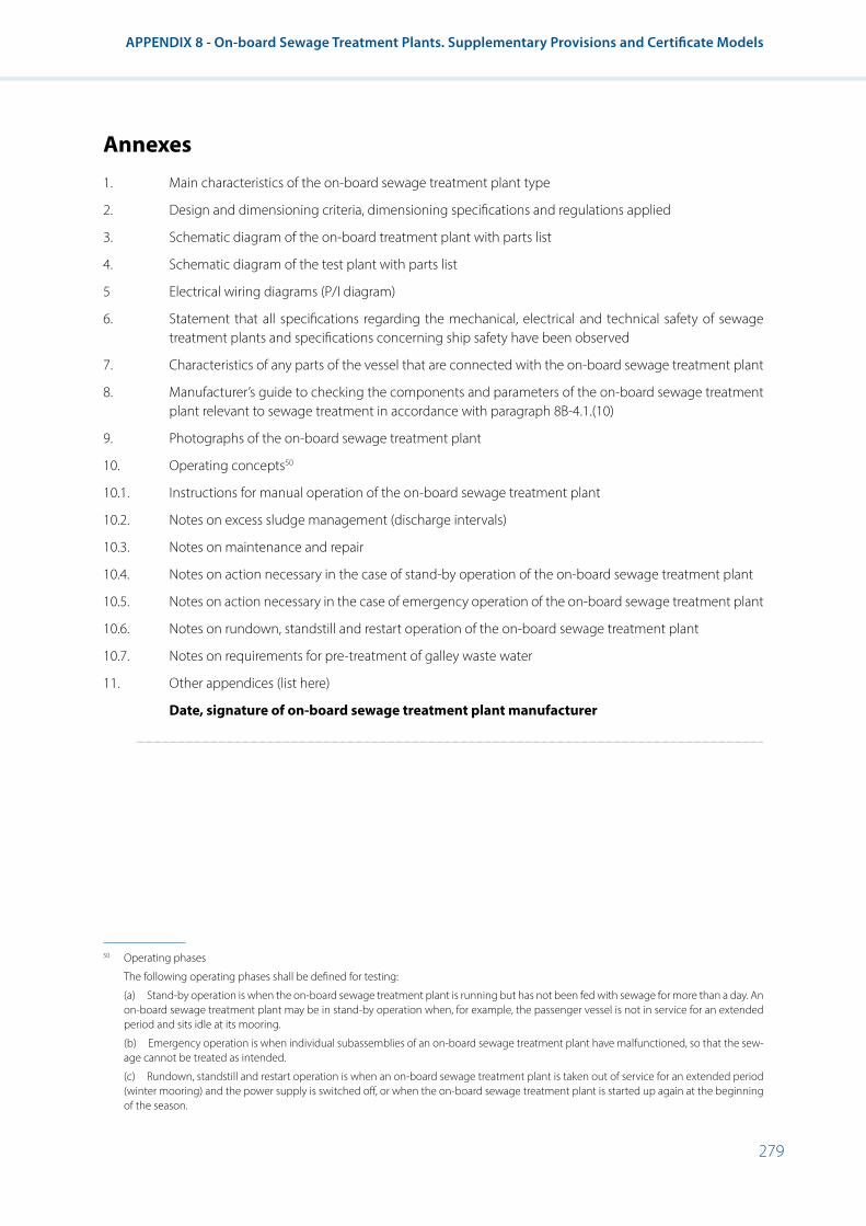
279
APPENDIX 8 - On-board Sewage Treatment Plants. Supplementary Provisions and Certificate Models
Annexes1. Main characteristics of the on-board sewage treatment plant type
2. Design and dimensioning criteria, dimensioning specifications and regulations applied
3. Schematic diagram of the on-board treatment plant with parts list
4. Schematic diagram of the test plant with parts list
5 Electrical wiring diagrams (P/I diagram)
6. Statement that all specifications regarding the mechanical, electrical and technical safety of sewage treatment plants and specifications concerning ship safety have been observed
7. Characteristics of any parts of the vessel that are connected with the on-board sewage treatment plant
8. Manufacturer’s guide to checking the components and parameters of the on-board sewage treatment plant relevant to sewage treatment in accordance with paragraph 8B-4.1.(10)
9. Photographs of the on-board sewage treatment plant
10. Operating concepts50
10.1. Instructions for manual operation of the on-board sewage treatment plant
10.2. Notes on excess sludge management (discharge intervals)
10.3. Notes on maintenance and repair
10.4. Notes on action necessary in the case of stand-by operation of the on-board sewage treatment plant
10.5. Notes on action necessary in the case of emergency operation of the on-board sewage treatment plant
10.6. Notes on rundown, standstill and restart operation of the on-board sewage treatment plant
10.7. Notes on requirements for pre-treatment of galley waste water
11. Other appendices (list here)
Date, signature of on-board sewage treatment plant manufacturer
...............................................................................................................................................................................................................................................................................................................................................................................................................................................................................................................
50 Operating phases
The following operating phases shall be defined for testing:
(a) Stand-by operation is when the on-board sewage treatment plant is running but has not been fed with sewage for more than a day. An on-board sewage treatment plant may be in stand-by operation when, for example, the passenger vessel is not in service for an extended period and sits idle at its mooring.
(b) Emergency operation is when individual subassemblies of an on-board sewage treatment plant have malfunctioned, so that the sew-age cannot be treated as intended.
(c) Rundown, standstill and restart operation is when an on-board sewage treatment plant is taken out of service for an extended period (winter mooring) and the power supply is switched off, or when the on-board sewage treatment plant is started up again at the beginning of the season.

280
Resolution No. 61 Revision 2
Addendum
Main characteristics of the on-board sewage treatment plant type (Model)
1. Description of the on-board sewage treatment plant
1.1 Manufacturer: ............................................................................................................................................................................................................................................................................................................................................................................................................................................
1.2 Serial number of the plant: ..................................................................................................................................................................................................................................................................................................................................................................................
1.3 Mode of treatment: biological or mechanical/chemical *
1.4 Upstream waste water storage tank? Yes, … m³/No *
2. Design and dimensioning criteria (including any special installation instructions or restrictions on use)
2.1 ...............................................................................................................................................................................................................................................................................................................................................................................................................................................................................................................
2.2 ...............................................................................................................................................................................................................................................................................................................................................................................................................................................................................................................
3. Dimensioning of the on-board sewage treatment plant
3.1 Maximum daily volumetric flow rate of sewage Qd [m³/d]: .........................................................................................................................................................................................................................................
3.2 Daily BOD5 pollution load [kg/d]: ...........................................................................................................................................................................................................................................................................................................................................................
* Specify as appropriate.

281
APPENDIX 8 - On-board Sewage Treatment Plants. Supplementary Provisions and Certificate Models
Part III - Type approval certificate (Model)Seal of the competent authority
Type approval No: ................................................................................ Extension No.: ....................................................................................
Notification of issuance/extension/refusal/withdrawal* of type approval for an on-board sewage treatment plant type in accordance with resolution No. 61
Reason for extension, if applicable: .......................................................................................................................................................................
Section I
0. General ...................................................................................................................................................................................................................................
0.1 Make (manufacturer’s company name): ............................................................................................................................................................
0.2 Manufacturer’s designation for the on-board sewage treatment plant type: ...........................................................................
0.3 Manufacturer’s type code corresponding to the information affixed to the on-board treatment plant: ................
.......................................................................................................................................................................................................................................................
Position: ..................................................................................................................................................................................................................................
Method of attachment: ................................................................................................................................................................................................
0.4 Manufacturer’s name and address: .......................................................................................................................................................................
.......................................................................................................................................................................................................................................................
Name and address of manufacturer’s authorised representative, if any: ......................................................................................
.......................................................................................................................................................................................................................................................
0.5 Position, coding and method of attachment of the serial number of the on-board sewage treatment plant: ...
.......................................................................................................................................................................................................................................................
.......................................................................................................................................................................................................................................................
0.6 Position and method of attachment of the type approval number: ...............................................................................................
.......................................................................................................................................................................................................................................................
0.7 Address(es) of production works: ..........................................................................................................................................................................
.......................................................................................................................................................................................................................................................
* Specify as appropriate.

282
Resolution No. 61 Revision 2
Section II
1. Any restrictions on use: ................................................................................................................................................................................................
1.1 Particularities to be observed when installing the on-board sewage treatment plant: ......................................................
.......................................................................................................................................................................................................................................................
1.1.1 .......................................................................................................................................................................................................................................................
1.1.2 .......................................................................................................................................................................................................................................................
2. Technical service responsible for carrying out the tests**
.......................................................................................................................................................................................................................................................
.......................................................................................................................................................................................................................................................
.......................................................................................................................................................................................................................................................
3. Date of test report: ..........................................................................................................................................................................................................
4. Number of test report: ..................................................................................................................................................................................................
5. The undersigned hereby certifies the accuracy of the manufacturer information in the annexed information document for the above mentioned on-board sewage treatment plant in accordance with appendix 9 of resolution No. 61 and the validity of the annexed test results in relation to the on-board sewage treatment plant type. The sample(s) has (have) been selected by the manufacturer with the agreement of the competent authority and submitted by the manufacturer as the design type of the on-board sewage treatment plant:
The type approval is issued/extended/refused/withdrawn: ***
Place: ........................................................................................................................................................................................................................................
Date: .........................................................................................................................................................................................................................................
Signature: ..............................................................................................................................................................................................................................
Appendices:
Information folder
Test results (see annex 1)
** In case tests are made by the competent authority, mark “not relevant”.*** Specify as appropriate.

283
APPENDIX 8 - On-board Sewage Treatment Plants. Supplementary Provisions and Certificate Models
Annex 1
Test results for type approval (Model)
0. General
0.1 Make (manufacturer’s company name): ............................................................................................................................................................
0.2 Manufacturer’s designation for the on-board sewage treatment plant type: ...........................................................................
1. Information on the implementation of the test(s)*.
1.1 Inflow values
1.1.1 Daily volumetric flow rate of sewage Qd [m³/d]: ..........................................................................................................................................
1.1.2 Daily BOD5 pollution load [kg/d]: ............................................................................................................................................................................
1.2 Purification efficiency
1.2.1 Evaluation of outflow values
Evaluation of outflow values BOD5 [mg/l]
Location Sample type
Number of tests that meet the
limit-values
Max
Min Value Phase Mean
Inflow 24h composite samples —**
Outflow 24h composite samples
Inflow Random samples —
Outflow Random samples
Evaluation of outflow values COD [mg/l]
Location Sample type
Number of tests that meet the
limit-values
Max
Min Value Phase Mean
Inflow 24h composite samples —
Outflow 24h composite samples
Inflow Random samples —
Outflow Random samples
* In case of more test cycles indicate for each cycle.** No limit values exist for the inflow.

284
Resolution No. 61 Revision 2
Evaluation of outflow values TOC [mg/l]
Location Sample type
Number of tests that meet the
limit-values
Max
Min Value Phase Mean
Inflow 24h composite samples —
Outflow 24h composite samples
Inflow Random samples —
Outflow Random samples
Evaluation of outflow values SRF [mg/l]
Location Sample type
Number of tests that meet the
limit-values
Max
Min Value Phase Mean
Inflow 24h composite samples —
Outflow 24h composite samples
Inflow Random samples —
Outflow Random samples
1.2.2 Purification efficiency (elimination efficiency) (%)
Parameter Sample type Min Max Mean
BOD5 24h composite samples
BOD5 Random samples
COD 24h composite samples
COD Random samples
TOC 24h composite samples
TOC Random samples
SRF 24h composite samples
SRF Random samples
1.3 Further parameters measured
1.3.1 Additional inflow and outflow parameters:
Parameter Inflow Outflow
pH
Conductivity
Temperature of liquid phases

285
APPENDIX 8 - On-board Sewage Treatment Plants. Supplementary Provisions and Certificate Models
1.3.2 The following operating parameters are – when available – to be recorded during sampling:
Concentration of dissolved oxygen in the bioreactor
Dry matter content in the bioreactor
Temperature in the bioreactor
Ambient temperature
1.3.3 Further operating parameters according to the manufacturer’s operating instructions
1.4 Competent authority or Technical service:
Place, date: ............................................................................................... Signature: ............................................................................................

286
Resolution No. 61 Revision 2
Part IV - Type-approvals numbering system1. System
The number shall consist of four sections separated by the “*” character.
Section 1: The small letter “e” followed by the distinguishing number of the State issuing the type-approval:
1 Germany 18 Denmark
2 France 19 Romania
3 Italy 20 Poland
4 Netherlands 21 Portugal
5 Sweden 23 Greece
6 Belgium 24 Ireland
7 Hungary 26 Slovenia
8 Czech Republic 27 Slovakia
9 Spain 29 Estonia
11 United Kingdom 32 Latvia
12 Austria 34 Bulgaria
13 Luxembourg 36 Lithuania
14 Switzerland 49 Cyprus
17 Finland 50 Malta
Section 2: The indication of the requirement level. The requirements regarding purification efficiency are likely to be stepped up in the future. The different requirement levels are denoted by Roman numerals, starting at level I.
Section 3: A four-digit sequential number (with leading zeroes as applicable) to denote the base type-approval number. The sequence shall start from 0001.
Section 4: A two-digit sequential number (with leading zero if applicable) to denote the extension. The sequence shall start from 01 for each number.
2. Examples
(a) Third type-approval (with as yet no extension) issued by the Netherlands corresponding to level I:
e 4*I*0003*00
(b) Second extension to the fourth type-approval issued by Germany corresponding to level II:
e 1*II* 0004*02

287
APPENDIX 8 - On-board Sewage Treatment Plants. Supplementary Provisions and Certificate Models
Part
V -
Sum
mar
y of
type
app
rova
ls fo
r on-
boar
d se
wag
e tr
eatm
ent p
lant
type
s
(M
odel
)
Seal
of t
he c
ompe
tent
aut
horit
y
List
No.
: .....
........
........
........
........
........
........
........
........
........
........
........
........
........
.......
Perio
d fro
m ..
........
........
........
........
........
........
........
........
........
........
........
........
.. to
...
........
........
........
........
........
........
........
........
........
........
........
........
........
........
.
12
34
56
7
Mak
e*M
anuf
actu
rer’s
de
signa
tion
Type
app
rova
l num
ber
Dat
e of
type
app
rova
lEx
tens
ion/
refu
sal/
with
draw
al**
Reas
on fo
r ext
ensio
n/re
fusa
l/with
draw
al
Dat
e of
ex
tens
ion/
re
fusa
l/
with
draw
alEr
ror!
Book
mar
k not
defi
ned.
* Re
leva
nt ty
pe-a
ppro
val c
ertifi
cate
.**
Sp
ecify
as a
ppro
pria
te.

288
Resolution No. 61 Revision 2
Part VI - Summary of on-board sewage treatment plants manufactured (Model)
Seal of the competent authority
List No.: ....................................................................................................................................................................................................................................
For the period from: ............................................................................ to: ..............................................................................................................
The following information is supplied relating to on-board sewage treatment plant types and type approval numbers of on-board sewage treatment plants manufactured within the above period in accordance with the provisions of resolution No. 61:
Make (manufacturer’s company name): ............................................................................................................................................................
Manufacturer’s designation for the on-board sewage treatment plant type: ...........................................................................
.......................................................................................................................................................................................................................................................
Type approval number: ................................................................................................................................................................................................
Date of issue: .......................................................................................................................................................................................................................
Date of first issue (in the case of extensions): .................................................................................................................................................
Serial number of the on-board sewage treatment plant:
... 001 ... 001 ... 001
... 002 ... 002 ... 002
. . .
. . .
. . .
..... m ..... p ..... q

289
APPENDIX 8 - On-board Sewage Treatment Plants. Supplementary Provisions and Certificate Models
Part
VII
- Dat
a sh
eet f
or o
n-bo
ard
sew
age
trea
tmen
t pla
nts
wit
h ty
pe a
ppro
val
(Mod
el)
Se
al o
f the
com
pete
nt a
utho
rity
On-
boar
d se
wag
e tre
atm
ent
plan
t cha
ract
erist
ics
Purifi
catio
n effi
cien
cy
No.
Dat
e of
type
ap
prov
al
Type
ap
prov
al
num
ber
Mak
eO
n-bo
ard
sew
age
treat
men
t pla
nt ty
peD
aily
vol
. flow
ra
te o
f sew
age
Qd
[m³/d
]
Dai
ly B
OD
5 po
llutio
n lo
ad [k
g/d]
BOD
5CO
DTO
C
24 h
co
mpo
site
sam
ple
Rand
om-
sam
ple
24 h
co
mpo
site
sam
ple
Rand
om-
sam
ple
24 h
co
mpo
site
sam
ple
Rand
om-
sam
ple

290
Resolution No. 61 Revision 2
Part VIII - On-board sewage treatment plant parameters record for special test (Model)
1. General
1.1 Particulars of the on-board sewage treatment plant
1.1.1 Make: ........................................................................................................................................................................................................................................
1.1.2 Manufacturer’s designation: ......................................................................................................................................................................................
.......................................................................................................................................................................................................................................................
1.1.3 Type approval number: ................................................................................................................................................................................................
1.1.4 Serial number of the on-board sewage treatment plant: .......................................................................................................................
.......................................................................................................................................................................................................................................................
1.2 Documentation
The on-board sewage treatment plant shall be tested and the test results recorded on separate sheets which shall be individually numbered, signed by the inspector and attached to this record.
1.3 Testing
Testing shall be carried out on the basis of the manufacturer’s guide to checking the components and parameters of the on-board treatment plant relevant to sewage treatment in accordance with paragraph 8B-4.1.(10). In justified individual cases inspectors may at their own discretion dispense with checking certain plant components or parameters.
During the test at least one random sample shall be taken. The results of the random sample measurement shall be compared with the control values set out in paragraph 8B-4.2.2, table 2.
1.4 This test report, together with the attached records, comprises a total of .................................................................. *pages
* To include by the tester.
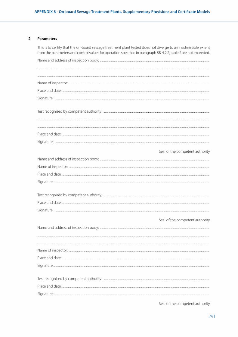
291
APPENDIX 8 - On-board Sewage Treatment Plants. Supplementary Provisions and Certificate Models
2. Parameters
This is to certify that the on-board sewage treatment plant tested does not diverge to an inadmissible extent from the parameters and control values for operation specified in paragraph 8B-4.2.2, table 2 are not exceeded.
Name and address of inspection body: .............................................................................................................................................................
.......................................................................................................................................................................................................................................................
.......................................................................................................................................................................................................................................................
Name of inspector: ..........................................................................................................................................................................................................
Place and date: ...................................................................................................................................................................................................................
Signature: ..............................................................................................................................................................................................................................
Test recognised by competent authority: ........................................................................................................................................................
.......................................................................................................................................................................................................................................................
.......................................................................................................................................................................................................................................................
Place and date: ...................................................................................................................................................................................................................
Signature: ..............................................................................................................................................................................................................................
Seal of the competent authority
Name and address of inspection body: .............................................................................................................................................................
Name of inspector: ..........................................................................................................................................................................................................
Place and date: ...................................................................................................................................................................................................................
Signature: ..............................................................................................................................................................................................................................
Test recognised by competent authority: ........................................................................................................................................................
Place and date: ...................................................................................................................................................................................................................
Signature: ..............................................................................................................................................................................................................................
Seal of the competent authority
Name and address of inspection body: .............................................................................................................................................................
.......................................................................................................................................................................................................................................................
.......................................................................................................................................................................................................................................................
Name of inspector: ..........................................................................................................................................................................................................
Place and date: ...................................................................................................................................................................................................................
Signature: ................................................................................................................................................................................................................................
Test recognised by competent authority: ........................................................................................................................................................
Place and date: ...................................................................................................................................................................................................................
Signature: ................................................................................................................................................................................................................................
Seal of the competent authority
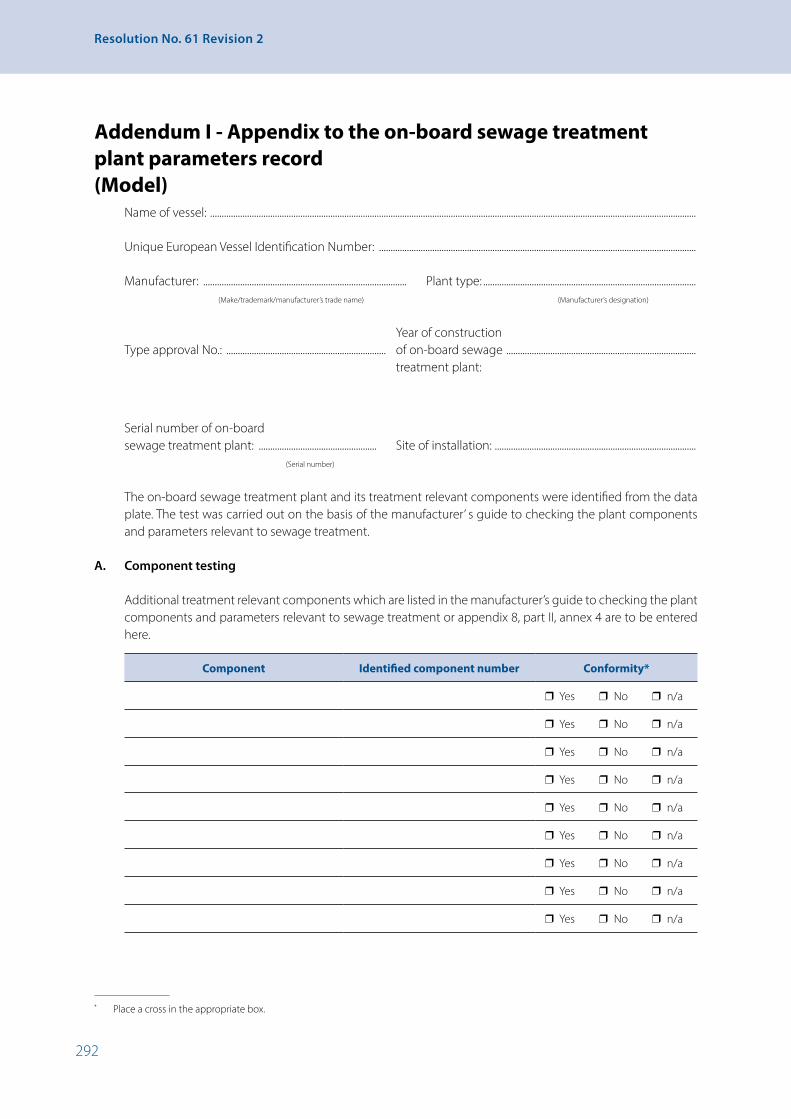
292
Resolution No. 61 Revision 2
Addendum I - Appendix to the on-board sewage treatment plant parameters record (Model)
Name of vessel: ..................................................................................................................................................................................................................
Unique European Vessel Identification Number: .........................................................................................................................................
Manufacturer: ........................................................................................ Plant type: ............................................................................................ (Make/trademark/manufacturer’s trade name) (Manufacturer’s designation)
Year of construction Type approval No.: ..................................................................... of on-board sewage .................................................................................. treatment plant:
Serial number of on-board sewage treatment plant: ................................................... Site of installation: ....................................................................................... (Serial number)
The on-board sewage treatment plant and its treatment relevant components were identified from the data plate. The test was carried out on the basis of the manufacturer’ s guide to checking the plant components and parameters relevant to sewage treatment.
A. Component testing
Additional treatment relevant components which are listed in the manufacturer’s guide to checking the plant components and parameters relevant to sewage treatment or appendix 8, part II, annex 4 are to be entered here.
Component Identified component number Conformity*
❒ Yes ❒ No ❒ n/a
❒ Yes ❒ No ❒ n/a
❒ Yes ❒ No ❒ n/a
❒ Yes ❒ No ❒ n/a
❒ Yes ❒ No ❒ n/a
❒ Yes ❒ No ❒ n/a
❒ Yes ❒ No ❒ n/a
❒ Yes ❒ No ❒ n/a
❒ Yes ❒ No ❒ n/a
* Place a cross in the appropriate box.

293
APPENDIX 8 - On-board Sewage Treatment Plants. Supplementary Provisions and Certificate Models
B. Results of random sample measurement
Parameter Value obtained Conformity*
BOD5 ❒ Yes ❒ No
COD ❒ Yes ❒ No
TOC ❒ Yes ❒ No
C. Comments
(The following deviating settings, modifications or alterations to the installed on-board sewage treatment plant were found.)
Name of inspector: ..................................................................................................................................................................
Place and date: ..................................................................................................................................................................
Signature: ..................................................................................................................................................................

294
Resolution No. 61 Revision 2
APPENDIX 9 - On-board Sewage Treatment Plant. Test Procedure1. General
1.1 Basics
The test specification shall be used to verify the suitability of on-board sewage treatment plants on passenger vessels.
In this procedure, the process and treatment technology used shall be examined and approved by means of a test plant. Conformity of the test plant with the treatment plants in service later is assured by applying identical design and dimensioning criteria.
1.2. Responsibility and test location
The test plant for a range of on-board sewage treatment plant types shall be tested by a technical service. The test conditions at the test site are the responsibility of the technical service and must correspond to the conditions specified here.
1.3 Documents to be submitted
The test shall be carried out on the basis of the information document in accordance with appendix 8, part II.
1.4 Plant dimensioning specifications
The on-board sewage treatment plants shall be dimensioned and designed such that the limit values specified in paragraph 8B-4.2.2, tables 1 and 2 in their outflow are not exceeded in the course of their operation.
2. Measures preparatory to testing
2.1 General
Prior to commencement of the test the manufacturer shall supply the technical service with structural and process specifications of the test plant, to include a complete set of drawings and supporting calculations in accordance with appendix 8, part II, and shall provide full information on the on-board sewage treatment plant’s requirements in terms of installation, operation and maintenance. The manufacturer shall supply the technical service with information on the mechanical, electrical and technical safety of the on-board sewage treatment plant to be tested.
2.2 Installation and putting into service
For the purpose of the test, the manufacturer shall install the test plant in such a way as to correspond to the intended installation conditions on board passenger vessels. Prior to testing the manufacturer must assemble the on-board sewage treatment plant and put it into service. Start-up must be in accordance with the manufacturer’s operating instructions and shall be checked by the technical service.
2.3 Run-in phase
The manufacturer shall notify the technical service of the nominal duration of the run-in phase up to normal operation in weeks. The manufacturer shall specify the point where the run in phase is deemed to be complete and testing may commence.
2.4 Inflow characteristics
Domestic raw sewage shall be used for testing the test plant. The inflow characteristics as regards pollutant concentrations shall be obtained from the on-board sewage treatment plant manufacturer’s dimensioning documentation in accordance with appendix 8, part II by forming the quotient for the

295
APPENDIX 9 - On-board Sewage Treatment Plant. Test Procedure
flow rate of organic substances in the form of a BOD5 load in kg/d and the design flow rate of sewage Qd in m³/d. The inflow characteristics shall be set accordingly by the inspection body in accordance with the following formula.
Calculation of the inflow characteristics
Domestic raw sewage shall be used for testing the test plant. The inflow characteristics as regards pollutant concentrations shall be obtained from the on-board sewage treatment plant manufacturer’s dimensioning documentation in accordance with appendix 8, part II by forming the quotient for the flow rate of organic substances in the form of a BOD5 load in kg/d and the design flow rate of sewage Qd in m³/d. The inflow characteristics shall be set accordingly by the inspection body in accordance with the following formula.
Calculation of the inflow characteristics
𝐶𝐶𝐶𝐶𝐵𝐵𝐵𝐵𝐵𝐵𝐵𝐵𝐷𝐷𝐷𝐷5𝑚𝑚𝑚𝑚𝑚𝑚𝑚𝑚𝑎𝑎𝑎𝑎𝑎𝑎𝑎𝑎
=𝐵𝐵𝐵𝐵𝐵𝐵𝐵𝐵𝐷𝐷𝐷𝐷5𝑄𝑄𝑄𝑄𝑑𝑑𝑑𝑑
�𝑘𝑘𝑘𝑘𝑔𝑔𝑔𝑔𝐵𝐵𝐵𝐵𝐵𝐵𝐵𝐵𝐷𝐷𝐷𝐷5 𝑑𝑑𝑑𝑑⁄𝑚𝑚𝑚𝑚3 𝑑𝑑𝑑𝑑⁄
�
Should calculation of the inflow characteristics result in a lower average BOD5 concentration of less than CBOD5mean = 500 mg/l, at least a mean BOD5 concentration
in the inflow water of CBOD5mean = 500 mg/l shall be set.
The technical service must not break up the inflowing raw sewage in a comminatory. Removal of sand (e.g. by screening out) is permissible.
3. Test procedure
3.1 Loading phases and hydraulic feeding
The test period shall comprise 30 test days. The test plant shall be fed on the test field with domestic waste water in accordance with the loading specified in table 1. Various loading phases shall be covered, with the test sequence taking account of normal loading phases and special loading phases such as overload, underload and stand-by operation. The duration of each loading phase (number of test days) is set out in table 1. The mean daily hydraulic load for each loading phase shall be set in accordance with table 1. The mean pollutant concentration, to be set in accordance with point 2.4, shall be kept constant.
Table 1 Load settings for each loading phase
Phase Number of test days Daily hydraulic load Pollutant concentration
Normal load 20 days Qd CBOD5 in accordance with 2.4
Overload 3 days 1.25 Qd CBOD5 in accordance with 2.4
Underload 3 days 0.5 Qd CBOD5 in accordance with 2.4
Stand-by 4 days Day 1 and day 2: Qd= 0 Day 3 and day 4: Qd
CBOD5 in accordance with 2.4
The special load phases overload, underload and stand-by operation shall be carried out consecutively without interruption; the normal load phase shall be divided into several part phases. The test shall start and end with a normal load phase, of at least five days’ duration in each case.
Daily hydraulic feeding hydrographs shall be set, depending on the specified operation of the on-board sewage treatment plant. The daily hydraulic feeding hydrograph shall be selected in accordance with the plant operation concept for the on-board sewage treatment plant. A distinction shall be made according to whether the on-board treatment plant is to be operated with or without an upstream sewage storage tank. The feeding hydrographs (daily hydrographs) are shown in figure 1 and figure 2.
Throughout the entire test period the hourly inflow must remain constant. The mean hourly volumetric flow rate of sewage Qh,mean is equivalent to 1/24 of the daily hydraulic
Should calculation of the inflow characteristics result in a lower average BOD5 concentration of less than CBOD5mean
= 500 mg/l, at least a mean BOD5 concentration in the inflow water of CBOD5mean = 500 mg/l shall
be set.
The technical service must not break up the inflowing raw sewage in a comminatory. Removal of sand (e.g. by screening out) is permissible.
3. Test procedure
3.1 Loading phases and hydraulic feeding
The test period shall comprise 30 test days. The test plant shall be fed on the test field with domestic waste water in accordance with the loading specified in table 1. Various loading phases shall be covered, with the test sequence taking account of normal loading phases and special loading phases such as overload, underload and stand-by operation. The duration of each loading phase (number of test days) is set out in table 1. The mean daily hydraulic load for each loading phase shall be set in accordance with table 1. The mean pollutant concentration, to be set in accordance with point 2.4, shall be kept constant.
Table 1 Load settings for each loading phase
Phase Number of test days Daily hydraulic load Pollutant concentration
Normal load 20 days Qd CBOD5 in accordance with 2.4
Overload 3 days 1.25 Qd CBOD5 in accordance with 2.4
Underload 3 days 0.5 Qd CBOD5 in accordance with 2.4
Stand-by 4 days Day 1 and day 2: Qd= 0Day 3 and day 4: Qd
CBOD5 in accordance with 2.4
The special load phases overload, underload and stand-by operation shall be carried out consecutively without interruption; the normal load phase shall be divided into several part phases. The test shall start and end with a normal load phase, of at least five days’ duration in each case.
Daily hydraulic feeding hydrographs shall be set, depending on the specified operation of the on-board sewage treatment plant. The daily hydraulic feeding hydrograph shall be selected in accordance with the plant operation concept for the on-board sewage treatment plant. A distinction shall be made according to whether the on-board treatment plant is to be operated with or without an upstream sewage storage tank. The feeding hydrographs (daily hydrographs) are shown in figure 1 and figure 2.
Throughout the entire test period the hourly inflow must remain constant. The mean hourly volumetric flow rate of sewage Qh,mean is equivalent to 1/24 of the daily hydraulic load according to table 1. The inflow shall be measured continuously by the technical service. The daily hydrograph must keep within a ± 5 % tolerance.
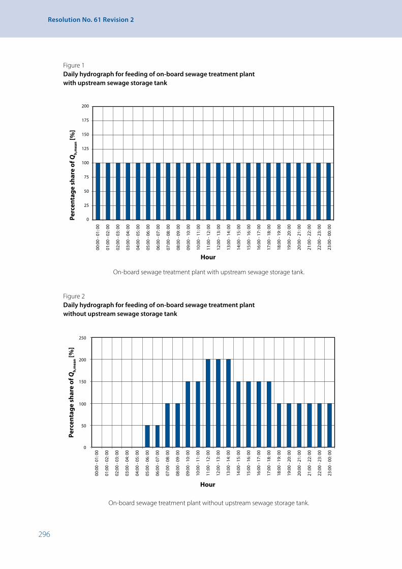
296
Resolution No. 61 Revision 2
Figure 1 Daily hydrograph for feeding of on-board sewage treatment plant
with upstream sewage storage tank
0
25
50
75
100
125
150
175
200
00:0
0 - 0
1: 0
0
01:0
0 - 0
2: 0
0
02:0
0 - 0
3: 0
0
03:0
0 - 0
4: 0
0
04:0
0 - 0
5: 0
0
05:0
0 - 0
6: 0
0
06:0
0 - 0
7: 0
0
07:0
0 - 0
8: 0
0
08:0
0 - 0
9: 0
0
09:0
0 - 1
0: 0
0
10:0
0 - 1
1: 0
0
11:0
0 - 1
2: 0
0
12:0
0 - 1
3: 0
0
13:0
0 - 1
4: 0
0
14:0
0 - 1
5: 0
0
15:0
0 - 1
6: 0
0
16:0
0 - 1
7: 0
0
17:0
0 - 1
8: 0
0
18:0
0 - 1
9: 0
0
19:0
0 - 2
0: 0
0
20:0
0 - 2
1: 0
0
21:0
0 - 2
2: 0
0
22:0
0 - 2
3: 0
0
23:0
0 - 0
0: 0
0
Hour
Perc
enta
ge s
hare
of Q
h,m
ean [%
]
On-board sewage treatment plant with upstream sewage storage tank.
Figure 2 Daily hydrograph for feeding of on-board sewage treatment plant
without upstream sewage storage tank
0
50
100
150
200
250
00:0
0 - 0
1: 0
0
01:0
0 - 0
2: 0
0
02:0
0 - 0
3: 0
0
03:0
0 - 0
4: 0
0
04:0
0 - 0
5: 0
0
05:0
0 - 0
6: 0
0
06:0
0 - 0
7: 0
0
07:0
0 - 0
8: 0
0
08:0
0 - 0
9: 0
0
09:0
0 - 1
0: 0
0
10:0
0 - 1
1: 0
0
11:0
0 - 1
2: 0
0
12:0
0 - 1
3: 0
0
13:0
0 - 1
4: 0
0
14:0
0 - 1
5: 0
0
15:0
0 - 1
6: 0
0
16:0
0 - 1
7: 0
0
17:0
0 - 1
8: 0
0
18:0
0 - 1
9: 0
0
19:0
0 - 2
0: 0
0
20:0
0 - 2
1: 0
0
21:0
0 - 2
2: 0
0
22:0
0 - 2
3: 0
0
23:0
0 - 0
0: 0
0
Hour
Perc
enta
ge s
hare
of Q
h,m
ean [%
]
On-board sewage treatment plant without upstream sewage storage tank.

297
APPENDIX 9 - On-board Sewage Treatment Plant. Test Procedure
3.2 Interruption or cancellation of the test
It may be necessary to interrupt the test if the test plant can no longer be operated properly due to power failure or the malfunction of a subassembly. The test may be interrupted for the duration of the repair. In such cases it is not necessary to repeat the whole of the test, only the loading phase in which the subassembly malfunction took place.
After the test is interrupted for a second time, the technical service shall decide whether the test may be continued or must be cancelled. The grounds for the decision must be stated and documented in the test report. Should the test be cancelled it must be repeated in full.
3.3 Examinations of purification efficiency and compliance with outflow limit values
The technical service shall take samples from the inflow to the test plant and analyse them in order to confirm conformity with the inflow characteristics. Sewage samples shall be taken from the outflow of the test plant and analysed to determine the purification efficiency and compliance with the required outflow limit values. Sampling carried out shall include both simple random samples and 24h composite samples. In the case of the 24h composite samples, either time proportional or flow proportional sampling may be carried out. The type of 24h composite sample shall be specified by the inspection body. Sampling in the inflow and outflow shall be carried out simultaneously and to the same degree.
In addition to the control parameters BOD5, COD and TOC the following parameters for inflow and outflow shall be measured in order to describe and represent the environmental and test conditions:
(a) Solids removable by filtration (SRF);
(b) pH;
(c) Conductivity;
(d) Temperature of liquid phases.
The number of examinations varies according to the relevant loading phase and is set out in table 2. The number of samplings relates to the inflow or outflow of the test plant.
Table 2 Specification of the number and timing of samplings in the inflow and outflow of the test plant
Loading phase Number of test days
Number of samplings Specification of timing of samplings
Normal load 20 days 24h composite samples: 8Random samples: 8
Sampling at regular intervals throughout the period
Overload 3 days 24h composite samples: 2Random samples: 2
Sampling at regular intervals throughout the period
Underload 3 days 24h composite samples: 2Random samples: 2
Sampling at regular intervals throughout the period
Stand-by 4 days 24h composite samples: 2Random samples: 2
24h composite sample: Sampling after inflow switched on and 24h later.Random sample: 1 hour after inflow switched on and 24h later.
Total number of 24h composite samples: 14 Total number of random samples: 14

298
Resolution No. 61 Revision 2
Where applicable, the following operating parameters shall also be measured from the random samples taken:
(a) Concentration of dissolved oxygen in the bioreactor;
(b) Dry matter content in the bioreactor;
(c) Temperature in the bioreactor;
(d) Ambient temperature;
(e) Other operating parameters in accordance with the manufacturer’s operating instructions.
3.4 Evaluation of examinations
In order to document the determined purification efficiency and to check adherence to process limit values, the minimum sample value (Min), the maximum sample value (Max) and the arithmetical mean (Mean) shall be specified as well as the individual measurement results for control parameters BOD5, COD and TOC.
The loading phase shall also be given for the maximum sample value. Evaluations shall be carried out for all loading phases jointly. The results shall be processed as shown in the following table:
Table 3a Specification for the statistical processing of data gathered – evaluation to document compliance
with outflow limit values
Max
Parameter Sampling typeNumber of test that meet the limit values Mean Min Value Phase
Inflow BOD5 24h composite samples –*
Outflow BOD5 24h composite samples
Inflow BOD5 random samples –
Outflow BOD5 random samples
Inflow COD 24h composite samples –
Outflow COD 24h composite samples
Inflow COD random samples –
Outflow COD random samples
Inflow TOC 24h composite samples –
Outflow TOC 24h composite samples
Inflow TOC random samples –
Outflow TOC random samples
Inflow SRF 24h composite samples –
Outflow SRF 24h composite samples
Inflow SRF random samples –
Outflow SRF random samples
* No limit values exist for the inflow.

299
APPENDIX 9 - On-board Sewage Treatment Plant. Test Procedure
Table 3b Specification for the statistical processing of data gathered – evaluation to document purification
efficiency
Parameter Sampling type Mean Min Max
Elimination efficiency BOD5 24h composite samples
Elimination efficiency BOD5 Random samples
Elimination efficiency COD 24h composite samples
Elimination efficiency COD Random samples
Elimination efficiency TOC 24h composite samples
Elimination efficiency TOC Random samples
Elimination efficiency SRF 24h composite samples
Elimination efficiency SRF Random samples
The remaining parameters in accordance with 3.3 (b) to (d) and the operating parameters in accordance with 3.3 shall be summarised in a table specifying the minimum sample result (Min), the maximum sample result (Max) and the arithmetical mean (Mean).
3.5 Compliance with the requirements of section 8B-4.
The limit values in accordance with paragraph 8B-4.2.2. Tables 1 and 2 shall be deemed to be upheld, when each value for the parameters COD, BOD5 and TOC:
(a) the mean values of the total of 14 outflow samples, and
(b) at least 10 of the total of 14 outflow samples do not exceed the specified limit values for 24h composite samples and random samples.
3.6 Operation and maintenance during testing
Throughout the testing the test plant shall be operated in accordance with the manufacturer’s specifications. Routine checks and maintenance work shall be carried out in compliance with the manufacturer’s operation and maintenance instructions. The excess sludge generated by the biological purification process may only be removed from the on-board sewage treatment plant if this is specified by the manufacturer in their operation and maintenance instructions. All maintenance work carried out shall be recorded by the technical service and documented in the test report. During the test no unauthorised persons may have access to the test plant.
3.7 Sample analysis/analysis method
The parameters to be studied shall be analysed using approved standard procedures. The standard procedure applied shall be specified.
4. Test report
4.1 The inspection body is required to compile a report on the type test carried out. The report shall include at least the following information:
• Details on the plant tested, such as its type, information on the nominal daily pollutant load and the dimensioning principles applied by the manufacturer;
• Information on the conformity of the on-board sewage treatment plant tested with the documentation provided before the testing;

300
Resolution No. 61 Revision 2
• Information on individual measurement results, as well as on the evaluation of the plant’s purification efficiency and compliance with the required outflow limit values;
• Details on the removal of excess sludge, such as the size of the volumes removed and the frequency of removal;
• Information on all operation, maintenance and repair work carried out during testing;
• Information on any deterioration in the quality of the on-board sewage treatment plant occurring during testing as well as any interruptions of testing;
• Information on any problems arising during testing;
• A list of responsible persons involved in the type testing of the on-board sewage treatment plant, giving their names and job titles;
• Name and address of the laboratory which carried out the analysis of the waste water samples;
• Analysis methods applied.
Examples of test sequences
Example 1
0
25
50
75
100
125
150
Hyd
raul
ic lo
ad Q
d [%
]
1 2 3 4 5 6 7 8 9 10 11 12 13 14 15 16 17 18 19 20 21 22 23 24 25 26 27 28 29 30
days
Normalload
Normalload
Normalload
Over-load
Under-load
StandBy
Normalload
0
25
50
75
100
125
150
Hyd
raul
ic lo
ad Q
d [%
]
1 2 3 4 5 6 7 8 9 10 11 12 13 14 15 16 17 18 19 20 21 22 23 24 25 26 27 28 29 30
days
Example 2
Normalload
Normalload
Normalload
Over-load
Under-load
StandBy
Normalload
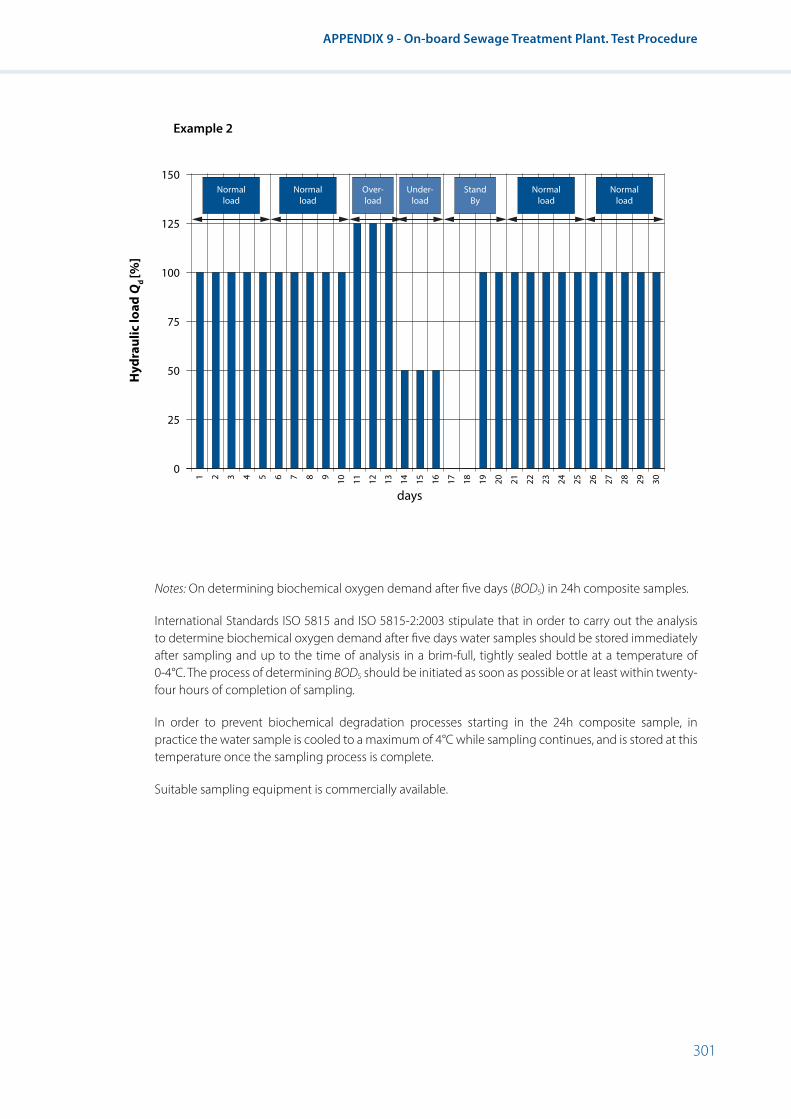
301
APPENDIX 9 - On-board Sewage Treatment Plant. Test Procedure
Example 2
Notes: On determining biochemical oxygen demand after five days (BOD5) in 24h composite samples.
International Standards ISO 5815 and ISO 5815-2:2003 stipulate that in order to carry out the analysis to determine biochemical oxygen demand after five days water samples should be stored immediately after sampling and up to the time of analysis in a brim-full, tightly sealed bottle at a temperature of 0-4°C. The process of determining BOD5 should be initiated as soon as possible or at least within twenty-four hours of completion of sampling.
In order to prevent biochemical degradation processes starting in the 24h composite sample, in practice the water sample is cooled to a maximum of 4°C while sampling continues, and is stored at this temperature once the sampling process is complete.
Suitable sampling equipment is commercially available.
0
25
50
75
100
125
150
Hyd
raul
ic lo
ad Q
d [%
]
1 2 3 4 5 6 7 8 9 10 11 12 13 14 15 16 17 18 19 20 21 22 23 24 25 26 27 28 29 30
days
Normalload
Normalload
Normalload
Over-load
Under-load
StandBy
Normalload
0
25
50
75
100
125
150
Hyd
raul
ic lo
ad Q
d [%
]
1 2 3 4 5 6 7 8 9 10 11 12 13 14 15 16 17 18 19 20 21 22 23 24 25 26 27 28 29 30
days
Example 2
Normalload
Normalload
Normalload
Over-load
Under-load
StandBy
Normalload


Reco
mm
enda
tions
on
Har
mon
ized
Eu
rope
-wid
e Te
chni
cal R
equi
rem
ents
fo
r Inl
and
Nav
igat
ion
Vess
els
Layout and Printing at United Nations, Geneva – 1835547 (E) – August 2020 – 117 – ECE/TRANS/SC.3/172/Rev.2
Recomm
endations on Harm
onized Europe-wide Technical Requirem
ents for Inland Navigation Vessels
Resolution No. 61, Revision 2
The pan-European recommendations for inland navigation vessels aim to establish a harmonized regime of technical requirements for vessels that transport goods and passengers internationally. The recommendations are the result of Government efforts to unify divergent regulations in force in different intergovernmental organizations and ECE member countries.
The recommendations were first adopted by the Working Party on Inland Water Transport (SC.3) in 1975 by resolution No. 17 and, since that time, they have been continuously revised and updated, followed by the adoption of resolution No. 61 in 2006 and its first revision in 2010.
The present second revision of the annex to resolution No. 61, adopted by SC.3 on 5 October 2018 at its sixty-second session as resolution No. 91, includes the amendments introduced by resolutions Nos. 72, 76 and 86 as well as other amendments adopted by SC.3 in 2013-2018.
Palais des NationsCH - 1211 Geneva 10, SwitzerlandTelephone: +41(0)22 917 12 34E-mail: [email protected]: http://www.unece.org
Information ServiceUnited Nations Economic Commission for Europe
UN
ECEU
NITED
NATIO
NS