recommendations for ductile and brittle failure … recommendations for ductile and brittle failure...
TRANSCRIPT

r
Recommendations for Ductile and Brittle Failure Design Criteria for Ductile Cast Iron Spent-Fuel Shipping Containers
This report was prepared as an account of work sponsored by an agency of the United States Government. Neither the United States Government nor any agency thereof, nor any of their employees, makes any warranty, express or implied, or assumes any legal liability or responsi- bility for the accuracy, completeness, or usefulness of any information, apparatus, product, or process disclosed, or represents that its use would not infringe privately owned rights. Refer- ence herein to any specific commercial product, process, or service by trade name, trademark, manufacturer, or otherwise does not necessarily constitute or imply its endorsement, recom- mendation, or favoring by the United States Government or any agency thereof. The views and opinions of authors expressed herein do not necessarily state or reflect those of the United States Government or any agency thereof.
Manuscript Completed: ~ ~ ~ i l 19B4 Date Published:
Prepared by M. W. Schwartz
Lawrence Livermore National Laboratory 7000 East Avenue Livermore, CA 94550
Prepared for Division of Engineering Technology Division of Nuclear Regulatory Research Office of Nuclear Reactor Regulation U.S. Nuclear Regulatory Commission Washington, D.C. 20555 NRC FIN No. A0374

DISCLAIMER
This report was prepared as an account of work sponsored by an agency of the United States Government. Neither the United States Government nor any agency Thereof, nor any of their employees, makes any warranty, express or implied, or assumes any legal liability or responsibility for the accuracy, completeness, or usefulness of any information, apparatus, product, or process disclosed, or represents that its use would not infringe privately owned rights. Reference herein to any specific commercial product, process, or service by trade name, trademark, manufacturer, or otherwise does not necessarily constitute or imply its endorsement, recommendation, or favoring by the United States Government or any agency thereof. The views and opinions of authors expressed herein do not necessarily state or reflect those of the United States Government or any agency thereof.

DISCLAIMER Portions of this document may be illegible in electronic image products. Images are produced from the best available original document.


i
ABSTRACT
This report presents recommendations for establishing design and acceptance criteria for the ductile cast iron to be used for fabricating spent-fuel shipping casks. ductile failure, and acceptance criteria for preventing brittle fracture, based upon drop testing a flawed prototype cask.
These recommendations address design criteria for preventing
iii

c

... - .......... . ....... . . . . . . . . . . . - ........ -. - - .. - . . . . . . . . . . . . .
CONTENTS
Chapter Page
iii LISTOFFIGURES . . vi i LIST OF TABLES . . . . . . . . . . . . . . . . . . Viii ACKNOWLEDGMENTS . . . . . . . . . . . . . . . . . ix EXECUTIVE SUMMARY . . 1 1. INTRODUCTION . . . . . . . . . . . . . . . . . 2 2. DUCTILE CAST IRON 3 3. RECOMMENDATIONS FOR DUCTILE FAILURE DESIGN CRITERIA 5
3.1 Minimum Material Properties . . . . . . . . . . 5 3.2 Design Stress Intensities . . . . . . . . . . . 5
Primary Membrane and Bending Stresses - Normal Conditions . . . . . . . . . . . . . . 5
3.4 Fatigue Analysis for Stresses . . . . . . . . . . 5 3.5 Primary and Secondary Stresses . . . . . . . . . 6 3.6 Primary Membrane and Bending Stresses -
Accident Conditions . . . . . . . . . . . . . 6 3.7 Total Stress-Intensity Range . . . . . . . . . . 6 3.8 Stress Concentration Factors . . . . . . . . . . 6
4. RECOMMENDATIONS FOR BRITTLE FRACTURE ACCEPTANCE CRITERIA . 8 4.1 DropTest . . . . . . . . . . . . . . . . 8 4.2 Test Conditions . . . . . . . . . . . . . . 8 4.3 Location of Test Flaws . . . . . . . . . . . . 8 4.4 Flaw Configuration . . . . . . . . . . . . . 8 4.5 Acceptance Criteria . . . . . . . . . . . . . 8 4.6 Maximum Allowable Flaw Size . . . . . . . . . . 9
5. VALUE IMPACT ASSESSMENT OF DUCTILE FAILURE DESIGN CRITERIA 10 5.1 Ductile Design Criteria . . . . . . . . . . . . 10
5.1.1 Minimum Material Properties . . . . . . . . 11 5.1.2 Design Stress Intensity Limit . . . . . . . 12 5.1.3 Primary Membrane and Bending Stress -
Normal Conditions . . . . . . . . . . . 14 5.1.4 Fatigue Analysis for Stresses . . . . . . . 15 5.1.5 Fatigue Curves . . . . . . . . . . . . 16 5.1.6 Allowable Fatigue Cycles . . . . . . . . . 16 5.1.7 Stress Concentration Factors . . . . . . . . 17 5.1.8 Primary and Secondary Stress . . . . . . . . 17 5.1.9 Fatigue Strength Reduction Factors . . . . . . 18 5.1.10 Primary Membrane and Bending Stresses -
Accident Conditions . . . . . . . . . . . 18
ABSTRACT. . . . 9 .
3.3
3.9 ASTM Specification . . . . . . . . . . . . . 7
V

Chapter Page
5 . 2 B r i t t l e F a i l u r e Acceptance C r i t e r i a . . . . 5 . 2 . 1 Drop T e s t . . . . . . . . . 5 . 2 . 2 S c a l e . . . . . . . . . . . 5 . 2 . 3 T e s t C o n d i t i o n s . . . . . . . 5 . 2 . 4 Locat ion of T e s t Flaws . . . . . 5 . 2 . 5 T e s t Flaw Conf igurat ion . . . . . 5 . 2 . 6 Acceptance C r i t e r i a . . . . . . 5 . 2 . 7 Maximum Allowable Flaw S i z e . . .
6 . REFERENCES. . . . . . . . . . . . . . APPENDIX A. RADIOLOGICAL RISK OF A CRACK I N A DUCTILE
APPENDIX B . FRACTURE TOUGHNESS STRESS INTENSITIES FOR CAST IRON CASK . . . . . . . . . . . . . BLUNT-TIP CRACKS . . . . . . . . . . . . .
. . . . 19 . . . . 19 . . . . 21 . . . . 2 1 . . . . 22 . . . . 23 . . . . 23 . . . . 25 . . . . 27
. . . . 28
. . . . 37
v i

LIST OF FIGURES
Page
c .
1. A-1.
B-1. B-2. B-3.
B-4. B-5. B-6.
The microstructure of ductile cast iron . . Simplified cross section of a ductile cast iron cask with a crack . . . . . . . . . . Coordinates of a blunt crack tip . . . . . Stress at a blunt crack prior to yield . . Comparison of the stress distribution between a
The plastic zone at the tip of a sharp crack . A sharp crack's plastic zone at instability . . The blunt crack's plastic zone when the sharp crack is unstable . . . . . . . . . .
sharp crack and a blunt crack . . . . . .
. . . 2 9 . . . 38 . . . 38
. . . 3 9 . . . 40 . . . 41
vii

LIST OF TABLES
4
4
1. ASTM A-536 grades of ductile cast iron . . . . . . . . 2. DIN-1693 (Federal Republic of Germany) grades
3 . DIN-1693 (Federal Republic of Germany) specifications of ductile cast iron . . . . . . . . . . . . . . for guaranteed properties of cast-on test specimens from ferritic grades of ductile cast iron . . . . . . . 4 Major fission product activities and characteristics at one year post-irradiation: specific power: 35 MW,
30 burnup: 25 000 MWD . . . . . . . . . . . . . . atoneyear. 31
(10.16-cm) thicknesses of iron
A-1.
A-2. Source characteristics for a full cask (16 assemblies)
A-3. Attenuation results for 16-in. (40.64-cm) and 4-in. . . . . . . . . . . . . . . . .
. . . . . . . . . . 34 A-4. Relative effect of a crack . . . . . . . . . . . . 35
36 A-5. Estimated surface dose rate at cracks . . . . . . . .
viii
ACKNOWLEDGMENTS
This report s u m izes the esult of research conducted to develop design criteria and fracture toughness acceptance criteria for spent-fuel shipping containers made from ferritic ductile cast iron. The work was done at Lawrence Livermore National Laboratory, and was funded by the Mechanical/ Structural Engineering Branch within the Division of Engineering Technology of the Nuclear Regulatory Commission.
The author wishes to thank Mr. K. Goldman of the Transnuclear,Corporation for his assistance in developing the value impact assessment with regard to industry, and Mr. M. E. Mount of LLNL's Environmental Science Division for his contribution to the radiological risk assessment of a damaged cask.
ix

EXECUTIVE SUMMARY
The purpose of this study was to develop recommendations for establishing design and acceptance criteria for the ductile cast iron to be used for fabricating spent-fuel shipping casks. Regulatory Guide 7.6 is not entirely applicable, since it presupposes that the material properties are available from Appendix I of the ASME Boiler and Pressure Code, or from an ASTM Standard specification. Since standards for ductile cast iron in the thicknesses used for spent-fuel shipping casks fo not exist, it is recommended that the license applicant supply the necessary data to support adopted stress intensity limits for both static and cycling loading conditions. In establishing stress intensity limits, a factor of four applied to the minimum ultimate tensile strength is recommended to determine h. The factors of 1.5% and 3%, which establish limits for the primary membrane plus bending stresses, and the primary plus secondary stresses, respectively, are based upon a minimum ductility requirement of 12% elongation. The same holds true for the factorsthat apply to accident conditions.
A drop test is recommended to qualify the ductile cast iron for brittle fracture. The test procedure is to be conducted in accordance with Appendix B of Regulatory Guide 7 . 8 . flaws introduced at locations of maximum primary and secondary stresses. If a flaw (other than one generated by fatigue cracking) is introduced, its depth should be at least 6 times that of a sharp-tip flaw, and its aspect ratio should not be greater than 1/6. Acceptance is to be based upon no significant flaw growth in areas of primary membrane or bending stress, and a maximum penetration of three-quarters of the thickness in areas of secondary stresses. Under no circumstances is the maximum allowable flaw size to be less than 10 mm. analyzed, and was found to be inconsequential.
A full-sized prototype cask is to be used, with
The effect of a part-through crack on radiological risk was
- 1 -

RECOMMENDATIONS FOR DUCTILE AND BRITTLE FAILURE DESIGN CRITERIA FOR DUCTILE CAST IRON SPENT-FUEL SHIPPING CONTAINERS
CHAPTER 1. INTRODUCTION
The U.S. Nuclear Regulatory Commission is developing Regulatory Guides for the design of, and the qualification for acceptance of, ductile cast iron shipping containers. A research program was conducted in fiscal year 1982 (FY82) to determine if Regulatory Guide 7.6 was applicable to ductile cast iron, for establishing design limits against ductile failure under both normal and accident conditions. This program also investigated various criteria for preventing brittle fracture in ship ing containers made from ductile cast iron. The results of this research were deliberately published without specific recommendations, since such recommendations are to be accompanied by a value impact assessment. Consequently, the present report recommends ductile design and brittle fracture acceptance criteria, and also considers the impact of these recommendations on the shipping container industry and on safety. Originally, our recommendations were to have been based solely upon the data collected during FY82. additional information received since then has also had an influence on the proposed recommendations. Assistance in evaluating the impact of the design criteria was obtained from the Transnuclear Corporation, which is one of the two existing firms having commercial experience with the design and production of spent fuel shipping containers made from ductile cast iron.
P
However,
- 2 -

CHAPTER 2. DUCTILE CAST IRON
The ductility of cast iron can be significantly improved by adding innoculants (such as magnesium) to produce a uniform dispersion of free graphite in the form of spherical particles, called nodules. This eliminates the sharp, crack-like notches that are characteristic of the more brittle gray cast irons, in which the graphite is dispersed as thin flakes. Maximum ductility is achieved when the matrix in which the graphite nodules are embedded is ferritic, as illustrated in Fig. 1. A fully ferritic microstructure can, however, be obtained only by heat treatment. iron contains some pearlite. This has the effect of increasing the iron's strength and hardness, at the expense of lower ductility. increased hardness and strength are advantageous for some applications, a number of grades of ductile cast iron are produced, covering a range of ferrite/pearlite ratios. In the United States, specifications for ductile cast irons are provided by the American Society for Testing Materials (ASTM) under ASTM A-536, which lists the five grades shown in Table 1. The three numbers in the grade designation refer to the ultimate tensile strength (UTS) , the yield strength (YS), and the percent elongation (e), respectively. Grade 60-40-18 is a fully ferritic ductile cast iron. represent microstructures with increasingly larger percentages of pearlite. Grade 120-90-02 is a martensitic type with a very high hardness and strength, which is obtainable only by using a quench-and-temper heat treatment. specification relevant to this study is the Federal Republic of Germany's (FRG's) D1N-1693. Its five grades, shown in Table 2, roughly parallel those of ASTM A-536. Grade GGG-40 is the German designation for a ferritic ductile cast iron. The properties shown in Table 2 are based upon tests performed on separately cast test specimens. The acceptance of castings weighing over 2000 kg with wall thicknesses of less than 20-cm may be based upon the minimum mechanical properties of cast-on test specimens, as shown in Table 3 for the ferritic grades.
As it is cast, the ductile cast
Because the
The next three grades
Another
Ferrite matrix \ /- Graphite
nodules
Pearlite matrix F e + Fe,C
(a) Ferritic (b) Pearlitic
Figure 1. The microstructure of ductile cast iron. - 3 -

Table 1. ASTM A-536 grades of ductile cast iron.
Ultimate tensile Yield strength Elongation strength (UTS) (YS) (e)
Grade (MPa 1 (MPa ( % I Matrix
60-40-18 414 65-45-12 448 80-55-06 552 100-70-03 689 12 0-9 0-0 2 827
276 310 379 683 621
18 12 Ferritic/pearlitic 6 Pearlitic/ferritic 3 Pear 1 it ic 2 Tempered martensitic
Fe r r i t ic
Table 2. DIN-1693 (Federal Republic of Germany) grades of ductile cast iron.
Ultimate tensile Yield strength Elongation strength (UTS) (YS) (e)
Grade (MPa 1 (MPa ( % I Matrix
GGG-40 400 GGG-40.3 400 GGG-50 500 GGG-6 0 600 GGG-70 700 GGG-8 0 800
250 250 320 380 440 500
15 Fer r it ic 18 Fer r it ic 7 Pearlitic/ferritic 3 Pear 1 it ic 2 Pearlitic 2 Tempered martensitic
Table 3. DIN-1693 (Federal Republic of Germany) specifications for guaranteed properties of cast-on test specimens from ferritic grades of ductile cast iron.
Ultimate tensile Yield strength Elongation strength (UTS) (YS) (e)
Grade (MPa 1 (ma) ( % I
GGG-40. 3 GGG-40
370 3 70
240 240
12 12
- 4 -

CHAPTER 3. RECOMMENDATIONS FOR DUCTILE FAILURE DESIGN CRITERIA
The following design criteria are recommended to the NRC staff for assessing the adequacy of ductile cast iron irradiated-fuel shipping cask designs (i.e. to see if the designs meet the structural requirements in paragraphs 71.35 and 71.36 of 10 CFR Part 71). These criteria are limited to ductile cast iron with a minimum elongation of 12%. All references in the present paper to the ASME Boiler and Pressure Vessel Code are to the 1982 edition.
3.1 Minimum Material Properties
ASTM material properties should be used, if available, to derive design stress-intensity values. Otherwise, material properties should be reported in accordance with Article IV-1000 of Revision I11 of the ASME Boiler and Pressure Vessel Code, and submitted to the NRC in the Safety Analysis Review (SAR). The values of material properties that should be used in the structural analysis are those values that correspond to the appropriate temperatures at loading.
3.2 Design Stress Intensities
The values for design stress intensities (E$,) for ductile cast iron should be less than the lesser of the two values: one-quarter of the minimum ultimate tensile strength, or one-half of the minimum yield strength.
3.3 Primary Membrane and Bending Stresses - Normal Conditions Under normal conditions, the value of the stress intensity resulting from the primary membrane stress should be less than the design stress intensity, S,, and the stress intensity resulting from the sum of the primary membrane stresses and the primary bending stresses should be less than 1.5%.
3.4 Fatigue Analysis for Stresses
The fatigue analysis for stresses under normal conditions should be performed as follows:
(1) Determine the value of Salt. point in the normal operating cycle should be considered, so that a maximum range can be determined.)
(The total stress state at each
(2) Design fatigue curves, similar to those in Appendix 1 of Section I11 of the ASME Boiler and Pressure Vessel Code, should be used for cyclic loading. E 606-80, entitled "Standard Recommended Practice for Constant- Amplitude Low-Cycle Fatigue Testing".
Fatigue testing should conform to ASTM standard
(3) If only one type of operational cycle is considered, the number of cycles corresponding to Salt (taken from the design fatigue curve for ductile cast iron) is the allowable life. If it is considered that two or more types of stress cycles produce significant Stresses, the rules for cumulative damage given in Article NB-3222.4 in Section I11 of the ASME Boiler and Pressure Vessel Code should be applied.
- 5 -

( 4 ) Appropriate stress concentration factors for structural discontinuities should be used. In regions where this factor is unknown, a value of four should be used.
3.5 Primary and Secondary Stresses
The stress intensity, Sn, associated with the range of primary plus secondary stresses, under normal conditions, should be less than 3%. The stress intensity is calculated in a manner similar to the calculation of 2Salt. However, the effects of local stress concentrations, which are considered in the fatigue calculations, are not included in this stress range.
The 3Sm limit just mentioned may be exceeded, if the following conditions are met:
(1) The range of stresses under normal conditions (excluding stresses due to stress concentrations and thermal bending stresses) yields a stress intensity, Sn, which is less than 3Sm.
(2) The value Sa, used for entering the design fatigue curver is multiplied by the factor &, where:
Ke = 1.0 , for Sn < 35, , Ke = 5 , for Sm > 3Sm .
- and
(3) The temperature of the ductile cast iron does not exceed 370OC.
(4) The ratio of the minimum specified yield strength of the ductile cast iron to the minimum specified ultimate strength is less than 0.8.
(These conditions can generally be met only when thermal bending stresses are a substantial portion of the total stress.)
3.6 Primary Membrane and Bending Stresses - Accident Conditions In an accident, the stress intensity resulting from the primary membrane stresses should be less than the lesser value of 2.4Sm or 0.5Su. Also, the stress intensity resulting from the sum of the primary membrane stresses and the primary bending stresses, should be less than the lesser value of 3.6Sm or 0.75Su.
3.7 Total Stress-Intensity Ranqe
The extreme total stress-intensity range of the initial state, the fabrication state, the normal operating conditions, and the conditions in an accident should be less than twice the value of Sa at 10 cycles, as given by the appropriate design fatigue curves.
3.8 Stress Concentration Factors
The appropriate stress concentration factors for structural discontinuities
- 6 -

i
should be used. A value of four should be used in regions where this factor is unknown.
3.9 ASTM Specification
A key condition of this recommendation is the requirement of Section 3 . 8 that a complete characterization of a new material be submitted in ASTM form. While the ASME Code further requires that the applicant simultaneously submit the new material specification to the ASTM for adoption as a standard, it is recognized that such a requirement could seriously delay the review process, OK even discourage a potential applicant from seeking a license. However, it is also recognized that an authoritative American standard for ductile cast iron, applicable to spent-fuel shipping containers, would be desirable. Such a standard would expedite the review process by removing the necessity for a detailed review of material properties for each license application. It would also assure uniformity of practice in setting design criteria, and provide uniform acceptance criteria for the material. Consequently, it is recommended that steps be taken to develop an ASTM standard for ductile cast iron, as applicable to spent fuel shipping containers. It is further recommended that future applicants be constrained to meet the requirements of this standard as a license condition, when it is formally adopted.
- 7 -

CHAPTER 4. RECOMMENDATIONS FOR BRITTLE FRACTURE ACCEPTANCE CRITERIA
4.1 Drop Test
The brittle fracture resistance of a prototype shipping cask made of ductile cast iron should be evaluated on the basis of full-scale drop tests, in accordance with the procedure outlined herein. Test casks of a size smaller than full scale are not acceptable.
4 . 2 Test Conditions
The test conditions should be in acccordance with those for the hypothetical accident conditions 3a and 3b, as specified in Regulatory Guide 7 . 8 . These are repeated here for convenience.
(1) Free Drop: The cask should be evaluated for a free drop through a distance of 30 ft (9 m) onto a flat unyielding horizontal surface. It should strike the surface in a position that is expected to inflict maximum damage, and should contain the maximum weight of contents.
(2) Puncture: The cask should be evaluated for a free drop of 4 0 in. (1 m) onto a stationary and vertical mild steel bar of 6 in. (15 cm) diameter, with its top edge rounded to a radius of not more than 0.25 in. (6.3 mm) . The bar should be of such a length as to cause maximum damage to the cask. The cask should contain the maximum weight of contents, and should hit the bar in a position that is expected to inflict maximum damage.
In addition, the tests shall be performed with the shipping container at a temperature that is not greater than -20°F (-29OC).
4.3 Location of Test Flaws
Flaws should be introduced in the casting at locations where maximum tensile stress levels are expected, and with an orientation that is normal to the direction of the stress. For each of the two test conditions, at least one flaw should be introduced at the location of the maximum primary stress and one at the location of the maximum secondary stress.
4.4 Flaw Configuration
The sizes and shapes of the flaws should be optional, with the applicant bearing in mind that the flaw size adopted will establish the inspection requirements. However, the aspect ratio of the flaw should not be greater than 1/6. knife-edge sharpening. In the case of the blunt crack, the radius of the crack tip should be no greater than 0.005 times the depth of the crack.
The crack tip may be blunt as a result of machining and subsequent
4.5 Acceptance Criteria
,
After the drop tests the flaw should not have propagated more than three-quarters of the way through the wall of the shipping container at
- 8 -

locations of secondary stress gradients. initiated fracturing at primary membrane or bending stress locations. "No initiation" should be interpreted as meaning no evidence of ductile tearing at a distance greater than 1/8 in. (3.2 mm) beyond the crack tip.
The flaw should also not have
4.6. Maximum Allowable Flaw Size
The maximum allowable flaw size for a production ductile cast iron shipping cask should be aJ6 for a blunt tip test flaw, where:
2 a = a ( K~~ (mi* ) ) .
C KID(flaw)
In this equation, a, is the minimum quasi-critical flaw size, aT equals the size of the test flaw, KID(flaw) equals the fracture toughness of the ductile cast iron at the site of the test flaw, and KID(minA equals the minimum fracture toughness of the ductile cast iron (derlve from samples taken from various locations in the prototype casting).
The maximum allowable flaw size should not be less than 10 mm (0.4 in.) deep.
- 9 -

CHAPTER 5. VALUE IMPACT ASSESSMENT OF DUCTILE FAILURE DESIGN CRITERIA
The recommendations outlined in Chapter 3 of this report are subjected to a value impact assessment from the point of view of their influence upon safety and cost. The present chapter recapitulates the specific recommendations and includes an associated value impact assessment. In general, the value of these recommendations to the NRC will be to provide a consistent basis for reviewing license applications for spent-fuel shipping containers manufactured from ductile cast iron. Similarly, these recommendations will be of value to the industry insofar as they form the basis for a guideline that, if adhered to, will facilitate the review process.
5.1 Ductile Design Criteria
During FY82, the applicability of Requlatory Guide 7.6 was assessed, using data on ferritic ductile cast iron available in the open literature. It was recognized that the mechanical properties of very large ductile cast iron shipping containers might be different from these reported data. because they were proprietary, data reflecting the properties of large castings were unavailable at the time. Since then, we have had access to some data about thick sections of ductile cast iron. Much is still proprietary, but the information available to us has influenced our assessment of ductile cast iron for use in shipping containers. Consequently, the recommendations in this report dealing with ductile failure design criteria for ductile cast iron have benefited from the information gathered since FY82.
However,
In assessing design criteria for the structural analyses of spent-fuel shipping containers made from ductile cast iron, we were (at first) guided by the provisions of Regulatory Guide 7.5. During FY82, each of the regulatory positions in this guide was assessed for its applicability to ferritic ductile cast iron, even though the positions were originally intended to apply to steel shipping containers.
Position 1 in Regulatory Guide 7.6 presents guidelines for establishing the design stress intensity limit, (Sm). Since design stress intensities for ductile cast iron are not included in Section I11 of the ASME Boiler and Pressure Vessel Code, the recommendations discussed in Article 111-2000 were used instead. The lesser of one-third of the minimum tensile strength, or two-thirds of the minimum yield strength, is specified for use as the design stress intensity limit. Since no data base had shown a yield strength for ductile cast iron of less than one-half its tensile strength, the tensile strength was considered the appropriate strength parameter for establishing design stress intensity limits. Position 1 further suggests using the ASTM material property values if ASME values are not given. For ferritic ductile cast iron, the minimum tensile strength reported in ASTM-A536 is 60.0 ksi (414 MPa). Thus, 20 ksi (138 MPa) seemed to be a valid stress intensity limit for this material. An analysis of the strength data in the open literature appeared to support this minimum tensile strength level, and the degree of dispersion of the data supports the adequacy of a safety factor of three.
However, since the FY82 research results were documented, other information relating to the material properties of thick-wall ductile iron castings had become available, which has influenced the recommendations outlined in this
- 10 -

report. 60-40-18, a full ferritizing. anneal is normally required. Large spent-fuel shipping containers made of ductile iron may not be heat treated. Therefore, even though they are described as "ferritic" ductile iron castings, their mechanical properties may be significantly less than grade 60-40-18. NO existing specification provides acceptable minima for thick-walled castings thicker than 8 in. (20 cm), except for the provision that such minima will be mutually agreed upon by the vendor and customer. It is not possible, therefore, to recommend stress intensity limits for cast shipping containers before these minimum mechanical properties have been established. Consequently, in the absence of ASME-recommended stress intensity limits and an applicable specification for thick-wall ductile iron castings, much of Regulatory Guide 7.6 is not applicable to ductile cast iron shipping containers.
To achieve the minimum strength and ductility level of grade
5.1.1 Minimum Material Properties
5.1.1.1 Recommendations
ASTM material properties should be used, if available, to derive design stress-intensity values. Otherwise, material properties should be .furnished in accordance with Article IV-1000 of Section I11 of the ASME Boiler and Pressure Vessel Code.
5.1.1.2 Impact on Safety
Safety considerations dictate the exclusive use of those materials that are well characterized with respect to their strength. Consequently, performing mechanical property tests is a fundamental requirement for materials used in safety related components, especially for a new material that lacks a universally accepted specification of its properties. Normally, only a material that has been evaluated and characterized by the ASTM is considered suitable for use. iron applicable to shipping containers, safety is assured if the information provided by the applicant is of such a nature that it would meet the requirements of the ASTM.
In the absence of such a specification for ductile cast ,
Guidance in this regard is provided by Article IV-1000 of Section I11 of the ASME Code, which deals with the procedure for obtaining approval of new materials. Normally the ASME adopts for inclusion in Section I11 only those materials for which there is an applicable ASTM specification. For other materials, the ASME recommends that the ASTM be requested to adopt a specification before presentation to a Code Committee. the ASTM specification, the Code Committee would consider the new material if it is presented in ASTM specification form, and if it includes all the data specified in paragraphs IV-1200 and IV-1300 of Article IV-1000. These data requirements are oriented toward the use of steels in a nuclear radiation environment, and may not be entirely applicable to ductile cast iron shipping containers. The provisions of Article IV-1000 that are applicable and should be addressed by the applicant are:
Pending publication of
(1) Provide a complete specification for the ductile cast iron to be used for the shipping container, including composition and microstructure.
- 11 -

(2) Supply adequate mechanical property data, which serve as a basis'for design stress-intensity limits. These data should include values for the ultimate tensile strength, yield strength, reduction in area, elongation, strain fatigue, creep strength, and creep rupture strength over the range of temperatures to which the ductile cast iron will be subjected.
( 3 ) Any heat treatment needed to realize the mechanical properties or microstructure should be fully described.
( 4 ) The brittle fracture characteristics of the material should be provided. The precise method for qualifying the ductile cast iron shipping container for resistance to brittle fracture is described in Section 5.2 of this report.
The specification of minimum mechanical properties of ductile cast iron is more appropriately treated in fabrication guidelines for this material.
5.1.1.3 Impact on Cost
The qualification of a new material, or of a conventional material for an application beyond its customary limits, mandates the use of a comprehensive test program. The costs involved are, therefore, not an unusual or unreasonable requirement, nor are they unanticipated by the potential applicant.
5.1.2 Design Stress Intensity Limit
5.1.2.1 Recommendation
The values for design stress intensities (S,,,) should be less than the lesser value of either one quarter of the minimum ultimate tensile strength or one half of the yield strength of the ductile cast iron, as revealed by test specimens obtained from a prototype casting.
5.1.2.2 Impact on Safety
The establishment of appropriate safety factors has a long history of controversy. This arises from the large number of uncertainties that influence the reliability of structures. These include uncertainties associated with material properties, mechanical loads and other environmental conditions, structural modeling, methods of analysis, and possible degradation of properties resulting from fabrication processes. The number and complexity of these uncertainties has made a rational approach to the establishment of safety factors difficult. In the absence of a universally acceptable technical basis, safety factor issues have generally been resolved by concensus among the members of code-writing groups. the establishment of design stress-intensity limits in Article 111-1120, as follows :
The ASME Code addresses
"The (design stress-intensity) values are obtained by applying (safety) factors to the mechanical properties of the materials. Consideration is given to the minimum properties specified and the properties at various temperatures as determined by tests on specimens of the material."
- 12 -

The code specifies the factors for ferritic steels, and for non-ferrous metals and alloys, in Article 111-2110. Position 1 of Regulatory Guide 7.6 refers the applicant to this article, when materials other than those appearing in Section I11 are encountered. Since the factors in Article 111-2110 may not apply to thick-section ductile iron castings, some other basis needs to be established for determining safety factors.
Although the ASME Code does not include design stress intensities for ductile cast iron in Section 111, it does deal with this material in Part UCD of Section VIII, Div. I, entitled "Requirements for Pressure Vessels Constructed Of Cast Ductile Iron." Here the maximum allowable stress is specified as 12 ksi. This represents a safety factor of 5 on the minimum ultimate tensile strength of 60 ksi that is characteristic of ASTM 60-40-18. Although not explicitly stated, this safety factor is based upon a design by formula approach. In addition, a casting quality factor is required for application to the design stress-intensity value; Section VIII, Paragraph UG-29(a) (1) specifies a quality factor of 80%, but it assumes that neither impact tests nor non-destructive examinations will be performed. On the other hand, a design-by-analysis approach is required under Section I11 of the ASME Code. Section VIII, Div. 1 of the Code requires a safety factor of 4 for steel components based on a design-by-formula approach, but in Section 111, Class 1 steel components may be designed by analysis, using a safety factor of three. Since shipping containers made of ductile cast iron will be based on a design-by-analysis approach, it is recommended that a safety factor of four be used for ferritic ductile cast iron. that fracture toughness characterization of ductile iron castings for spent- fuel shipping containers will be pursued, and that intensive NDE tests will be performed, a quality factor of unity can be applied.
Furthermore, since it is anticipated
A safety factor of four is considered adequate for ensuring the integrity of the shipping cask when a design-by-analysis approach is adopted. This is larger than the safety factor of three recommended by Section I11 of the ASME Boiler and Pressure Vessel Code, but it reflects the conservative philosophy of the code in assigning larger safety factors for ductile cast iron than for steel. There is as yet insufficient experience with the behavior of thick- wall ductile iron for shipping casks to allow a lesser degree of conservatism. On the other hand, a safety factor of five (as recommended in Section VI11 of the ASME Code for pressure vessels made of ductile cast iron) is too high, since it is based upon a design-by-formula approach rather than upon the design-by-analysis approach, as required by Section I11 of the code. The differences in the ap roach which allow a reduction in safety factor for design by analysis are: 2 3
(1) Section I11 uses the maximum shear (Tresca) theory of failure, instead of the maximum stress theory, resulting in more realistic stress intensity levels for biaxial stress conditions.
(2) Section I11 requires the detailed calculation and classification of all stresses, and the application of different stress limits to different classes of stress, whereas Section VI11 merely gives formulas for the minimum allowable wall thickness.
- 13 -

( 3 ) Section 111 requires the calculation of thermal stresses and provides the allowable values for them.
( 4 ) Section I11 considers the feasibility of fatigue failure and gives rules for its prevention.
(5) Finally, Section I11 requires that protection against non-ductile fracture be provided.
Since a design-by-analysis approach is required for safety related components for shipping casks, a safety factor of four rather than five is adequate.
5.1.2.3 Impact on Cost
While a safety factor of four rather than three would imply a cost penalty by requiring heavier sections under similar loading conditions, the containment thickness of the ductile cast iron shipping cask is based upon shielding requirements, rather than upon strength. Thus, a safety factor of four is not expected to require a more massive containment structure than would result from using a safety factor of three, so that this recommendation is not expec ted to have an impact on costs.
5.1.3 Primary Membrane and Bending Stress - Normal Conditions
5.1.3.1 Recommendation
Under normal conditions, the value of the stress intensity resulting from primary membrane stress should be less than the design stress intensity, Sm, and the stress intensity resulting from the sum of the primary membrane stresses and the primary bending stresses should be less than 1.5 h.
Position 2 of Regulatory Guide 7.6 suggests that under normal conditions the value of the stress intensity resulting from the primary membrane stress should be less than the design stress intensity, Sm. This deviates somewhat from ASME Section I11 NB-3211 (a), which states that the design shall be such that the stress intensities will not exceed the prescribed limits. However, the wording of Regulatory Guide 7.6 is preferred, since it implies that the margin between the computed stress intensity and the design stress intensity should be judiciously considered. It is conceivable that a reduction in design stress intensity may be required, if production castings do not quite meet minimum tensile strength specifications. In this case, a comfortable margin of safety with respect to S, could facilitate a decision involving the acceptance of a production casting.
Position 2 of Regulatory Guide 7.6 also suggests that the stress intensity resulting from the sum of the primary membrane stresses and the primary bending stresses should be less than 1.5 S,,,. "shape factor" of a beam with a rectangular cross section, where collapse occurs as a result of the formation of a plastic hinge. For the large safety factors used, a stress factor of 1.5 would limit the maximum stress to a level below the yield strength of ductile cast iron. Even if the combined primary
This limitation stems from the
- 14 -

stresses were so high that a plastic hinge condition was approached, the strain at the extreme fiber of the beam will be well below the fracture strain. Consequently, the factor of 1.5 for the sum of the primary membrane and bending stresses under normal conditions is applicable for ductile cast iron. This factor of 1.5 only applies to structures in bending, with a rectangular cross section. For other cross sections this factor may be significantly lower. However, for shell structures the factor of 1.5 is applicable to primary bending stresses along the thickness of the shell.
5.1.3.2 Impact on Safety
This recommendation reiterates position 2 of Requlatory Guide 7.6. guideline is designed for steel structures, adherence to it will ensure the
While this
safe use of a ductile cast iron, provided that its ductility allows the formation of a plastic hinge in a deformed beam before a condition of ultimate strain develops at the extreme fiber.
5.1.3.3 Impact on Cost
Providing sufficient ductility in thick-wall ductile iron castings is a major fabrication problem. Ductility, in terms of percent elongation, has tended to be low and to display a wide scatter band. special fabricating processes to consistently achieve acceptable levels of ductility. procedures used to achieve the required ductility levels, and will vary from one manufacturer to the next. Because of the highly proprietary nature of the fabrication processes for shipping containers made of ductile cast iron, it has not been possible to assess the impact of ductility requirements on costs in a more specific manner.
It may be necessary to resort to
The cost involved will depend upon the specific fabrication
5.1.4 Fatigue Analysis for Stresses
5.1.4.1 Recommendation
The fatigue analyses for stresses under normal conditions should be performed by determining the value of salt. the normal operating cycle should be considered, so that a maximum range may be determined .
The total stress state at each point in
5.1.4.2 Impact on Safety
This recommendation reiterates position 3a of Regulatory Guide 7.6. reflects the approach recommended by Section I11 of the ASME code and is, consequently, a prudent and universally recognized procedure for fatigue analyses in the nuclear industry.
It
5.1.4.3 Impact on Cost
Applying this recommendation to shipping containers made of ductile cast iron would have no greater impact on costs than it has on shipping containers made of steel.
- 15 -

1
I
5.1.5 Fatigue Curves
5.1.5.1 Recommendation
Design fatigue curves similar to (and derived in the same manner as) those in Appendix I of Section I11 of the ASME Boiler and Pressure Vessel Code should be used for cyclic loading.
The FY82 investigation of the applicability of ASME design fatigue curves to ductile cast iron indicated that they were valid in the range of high-cycle fatigue above lo5 cycles to failure. However, the data used to suggest this may not have represented the fatigue properties of thick-section ductile cast iron. Consequently, if fatigue is a design condition that needs to be addressed, it is recommended that tests be performed to establish fatigue properties of as-cast ductile iron; just as tests are required to establish design stress-intensity limits. involving both high-cycle and low-cycle fatigue. in the material specifications supplied by the applicant, as outlined in Section 5.1. The fatigue data should be presented in the form of curves similar to those appearing in Appendix I of Section I11 of the ASME Boiler and Pressure Vessel Code, which are based upon uniaxial strain cycling. Since these curves will be specific for ductile cast iron, it will not be necessary to make adjustments for the modulus of elasticity (as described in position 3c of Regulatory Guide 7.6).
This would apply to design conditions Such data would be included
5.1.5.2 Impact on Safety
See Section 5.1.2.2.
5.1.5.3 Impact on Cost
See Section 5.1.2.3.
5.1.6 Allowable Fatigue Cycles
5.1.6.1 Recommendation
If only one type of operational cycle is considered, the number of cycles corresponding to Salt (taken from the design fatigue curve for ductile cast iron) is the allowable fatigue life. If two or more types of stress cycles are considered as being capable of producing sigificant stresses, the rules for cumulative damage (given in Article NB-3222.4 of Section I11 of the ASME Boiler and Pressure Vessel Code) should be applied.
5.1.6.2 Impact on Safety
This recommendation reiterates portions of position 3c of Regulatory Guide - 7.6. applicable to a wide range of materials, including ductile cast iron. Since it cites the ASME Code, it can be considered a prudent and universally recognized procedure for establishing an allowable number of fatigue cycles.
Although this guideline is designed for steel structures, the rule is
- 16 -
*

t
5.1.6.3 Impact on Cost
Applying this recommendation to shipping containers made of ductile cast iron would have no greater impact on costs than it has on shipping containers made of steel.
5.1.7 Stress Concentration Factors
5.1.7.1 Recommendation
Appropriate stress concentration factors for structural discontinuities should be used. A value of four should be used in regions where this factor is unknown.
5.1.7.2 Impact on Safety
This recommendation reiterates position 3d of Regulatory Guide 7.6. Although this guideline is designed for steel structures, the rule is applicable to a wide range of materials, including ductile cast iron.
5.1.7.3 Impact on Cost
See Section 5.1.6.3.
5.1.8 Primary and Secondary Stress
5.1.8.1 Recommendation
The stress intensity, Sn, associated with the range of primary plus secondary stresses under normal conditions should be less than 3%. calculation of this stress intensity is similar to the calculation of 2S,lt,. However, the effects of local stress concentrations, which are considered In the fatigue calculations, are not included in this stress range.
The
5.1.8.2 Impact on Safety
This recommendation reiterates a portion of position 4 in Regulatory Guide 7.6. The secondary stresses referred to here are those which are self limiting. These include general thermal stresses and bending stresses at gross structural discontinuities. Local yielding and minor distortions can satisfy the conditions that cause the stress to occur, and failure from one application of the stress is not to be expected. Safety is ensured by creating a condition of "elastic shakedown" whereby, even if the yield strength is exceeded slightly, the stress range may be as high as 2ay before further plastic deformation can occur. For ductile cast iron, when a design stress intensity based on one-quarter of the ultimate tensile strength and a ratio of yield to ultimate strength of about two-thirds is used, the range of primary plus secondary stresses can be as high as 5% to maintain the 2oY elastic range. Therefore a very conservative design criterion for ductile cast iron is implied by S m L 3Sm.
5.1.8.3 Impact on Costs
Applying this recommendation to shipping containers made of ductile cast iron
- 17 -

would have no greater impact on costs than it has on shipping containers made of s tee1 . 5.1.9 Fatigue Strength Reduction Factors
5.1.9.1 Recommendations
The 3% limit for fatigue analysis may be exceeded, if the conditions are met:
(1) If the range of stresses under normal conditions due to stress concentrations and thermal bending stress intensity, Sn, that is less than 3%.
following
(excluding stresses stresses) yields a
( 2 ) If the value of Sa used in the design fatigue curve is multiplied by a factor Kef where:
Ke = 1.0 , for Sn < 3Sm , - or
K, = 5.0 , for Sn 3Sm . (3) If the temperature of the ductile cast iron does not exceed 37OOC.
( 4 ) If the ratio of the minimum specified yield strength of the ductile cast iron to the minimum specified ultimate strength is less than 0.8.
5.1.9.2 Impact on Safety
The recommendations reiterate positions 4a to 4d of Regulatory Guide 7.6, except for the fatigue-strength reduction factors. Regulatory Guide 7.6 were taken directly from Section I11 of the ASME Code (NB-3228.5), and are to be computed using the values of m and n that are furnished for a variety of materials (but not for ductile cast iron). The ASME Code, however, recommends that (except for the case of crack-like defects) no fatigue reduction factor greater than five need be used. Unless fatigue reduction factors are determined experimentally in accordance with 11-1600 of ASME Code Appendix 11, conservatism dictates that a K, of five be used for fatigue stresses that are greater than 3Sm.
The factors used in
5.1.9.3 Impact on Cost
If thermal stresses are a significant component of the fatigue stress, such that 3Sm is exceeded and increasing Sa by a factor of five results in an intolerable design condition, then appropriate analytical methods should be used (or experimental tests performed) to justify a lower fatigue-strength reduction factor.
5.1.10 Primary Membrane and Bending Stresses - Accident Conditions 5.1.10.1 Recommendation
Under accident conditions, the value of the stress intensity resulting from
t
- 18 -

the primary membrane stresses should be less than the lesser value of 2.4Sm or 0.5Su; and, the stress intensity resulting from the sum of the primary membrane stresses and the primary bending stresses should be less than the lesser value of 3.6Sm or 0.75Su.
5.1.10.2 Impact on Safety
This recommendation is similar to that of position 6 of Regulatory Guide 7.6. However, the coefficients associated with Sm are reduced to reflect a safety factor of four for ductile cast iron, rather than using the safety factor of three for steel. Although Regulatory Guide 7.6 is designed for steel structures, adhering to it will ensure the safe use of ductile cast iron; provided that the ductility specification allows a plastic hinge in a deformed beam to form before the ultimate stress develops at the extreme fiber.
5.1.10.3 Impact on Cost
See Sections 5.1.1.3 and 5.1.3.3.
5.2 Brittle Failure Acceptance Criteria
5.2.1 Drop Test
5.2.1.1 Recommendation
The resistance of shipping casks made from ductile cast iron to brittle fracture should be evaluated on the basis of a full-scale drop test, in accordance with the procedure outlined in Chapter 4.
In the FY82 study, three approaches were described for qualifying ductile cast iron for resistance to brittle fracture. The first was a fracture arrest approach that examined ductile cast iron's ability to (in effect) display upper shelf toughness properties at -20°F (-29OC). The second was a classical linear elastic fracture mechanics approach that attempted to define maximum allowable flaw sizes at yield stress levels based upon the available data for ductile cast iron's dynamic fracture toughness. The third approach was to perform a full-scale drop test at -20°F (-29OC), in an orientation that could cause the maximum amount of damage, with a flaw introduced at the most critically stressed location.
Valid nil ductility transition temperature (NDTT) values for ductile cast iron can not be obtained. In addition, the experimental values of NDTT reported in the literature are too high to prevent unstable fracture of through-thickness cracks for the anticipated casting thickness. Consequently, the fracture- arrest approach was eliminated from further consideration. Furthermore, the available data on thesdynamic fracture toughness of ductile cast iron was such that, at yield stress levels, the ability to resist fracture initiation could not be affirmed by analysis, except by specifying maximum allowable flaw sizes that current practice considers too small to detect.
5.2.1.2 Impact on Safety
Safety considerations dictate that the integrity of the spent-fuel containment
- 19 -

not be compromised as a result of catastrophic crack propagation under dynamic loading conditions. Qualification of the cask by analytical methods would require assuming minimum anticipated fracture mechanics properties, maximum anticipated stress levels, and a limitation on the maximum allowable flaw size. Given the present state of knowledge, a conservative analysis would require assuming a low level of fracture toughness and a yield strength level of stress which restricts the maximum allowable flaw sizes to those that state-of-the-art NDE would not guarantee as being detectable with an acceptable level of reliability. Thus, an analytical approach cannot, as yet, assure the prevention of brittle fracture under dynamic loading conditions.
many uncertainties that an analytical approach is forced to take into account. First, the containment is subjected to dynamic loading conditions that (at present) are considered t o be conservatively representative of severe accident conditions. No assumption, therefore, need be made regarding the maximum stress levels. Secondly, the response of the ductile iron cask to the dynamic loads in simulated accident conditions may be more benign than conservative analytical models of its behavior would allow. be the possibility that the graphite nodules in the iron inhibit a reduction in fracture toughness by limiting the size of flaws to the distance between nodules. Another possibility is that the elastic strain energy (due to tensile forces) that remains after dissipation by the inelastic deformation of other cask components, is not sufficient for catastrophic crack propagation. Finally, introducing flaws creates a condition of vulnerability that provides a basis for establishing limits on flaw size (given a successful test) which, with a high degree of reliability, obviates flaw propagation under the conditions simulated by the drop test.
. On the other hand, a drop test performed in accordance with 10 CFR 71 removes
An example would
The principal ingredients for such a test that assure safety against brittle fracture are:
( 3 )
( 4 )
(5)
Using a full-scale ductile iron cask for the qualifying test, which will most accurately reflect the brittle fracture behavior of subsequent production casks.
Identifying the most critically stressed areas for placement of the test flaws.
Introducing test flaws at these most critically stressed areas.
Comparing the fracture toughness of the material in the vicinity Of the flaw with a lower-bound fracture toughness value, representative of the test cask, to establish the quasi-critical flaw size.
Correlating the lower-bound fracture toughness values of the test cask with the corresponding lower-bound values of cast-on or separately cast test blocks. This correlation will provide the basis for accepting subsequent production casks whose fracture toughness properties cannot be directly assessed by destructive tests.
Establishing a maximum allowable flaw size for subsequent production casks, based upon the safety factor applied to the quasi-critical test flaw.
- 20 -

5.2.1.3 Impact on C o s t
The d r o p - t e s t program requires a c o n s i d e r a b l e commitment o f funds to q u a l i f y t h e d u c t i l e cast i r o n s h i p p i n g cask f o r r e s i s t a n c e t o b r i t t l e f r a c t u r e . However, t h e costs would n o t be i n t o l e r a b l y g r e a t e r t h a n t h o s e f o r per forming a d r o p tes t to q u a l i f y t h e cask's r e s i s t a n c e to g e n e r a l damage mechanisms. The p r o t o t y p e cask used for t h e test shou ld be r e p r e s e n t a t i v e o f subsequen t p r o d u c t i o n casks, so t h a t t h e costs f o r e n g i n e e r i n g , d e s i g n , p r o c e s s development , and q u a l i t y a s s u r a n c e p rocedures are r e c o v e r a b l e . The cost of t h e c a s t i n g would be no g r e a t e r t h a n t h a t for a c o n v e n t i o n a l d r o p test , e x c e p t for t h e a d d i t i o n a l cost o f i n t r o d u c i n g t h e f laws . S i n c e t h e test cask is sacr i f ic ia l , it c a n also f u r n i s h test specimens f o r c h a r a c t e r i z i n g t h e d u c t i l e cast i r o n ' s as-cast material properties, b o t h f o r e s t a b l i s h i n g f a i lu re c r i t e r i a and s t a n d a r d s f o r a c c e p t i n g p r o d u c t i o n casks.
5.2.2 S c a l e
5.2.2.1 Recommendation
The tes t cask used i n t h e d r o p test s h o u l d be a full-scale p r o t o t y p e model t h a t is r e p r e s e n t a t i v e o f subsequen t p r o d u c t i o n casks.
5.2.2.2 Impact on S a f e t y
I t is sometimes advantageous to u s e small-scale models for de te rmin ing mechanica l responses f o r v a l i d a t i n g s t ruc tu ra l a n a l y s e s . However, w e are concerned h e r e w i t h t h e l i k l i h o o d of f r a c t u r e , which i n v o l v e s knowing t h e f a i l u r e c r i t e r i a for d u c t i l e cast i r o n . I n t h e case of l a r g e d u c t i l e i r o n c a s t i n g s , w e c a n n o t r e l y on s e p a r a t e l y cast samples or cas t -on test pieces to a c c u r a t e l y ref lect t h e fracture toughness o f t h e s h i p p i n g c o n t a i n e r , s i n c e t h i s material p r o p e r t y var ies w i t h t h e s i z e o f t h e c a s t i n g and t h e process v a r i a b l e s i n its p roduc t ion . a s s u r a n c e t h a t it is r e p r e s e n t a t i v e o f t h e f u l l - s i z e c a s t i n g . Fur thermore , t h e f l a w s i z e s and l i m i t s on p r o p a g a t i o n can be s p e c i f i e d w i t h fa r less ambigui ty for a f u l l - s c a l e c a s k t h a n can be done for a sub-scale model. Consequent ly , o n l y full-scale production models o f d u c t i l e cast i r o n s h i p p i n g casks shou ld s e r v e a s a b a s i s for q u a l i f y i n g r e s i s t a n c e to b r i t t l e fracture.
Thus, a sub-scale c a s t i n g w i l l n o t g i v e comple te
5.2.2.3 Impact o n C o s t
See S e c t i o n 5.2.1.3.
5.2.3 T e s t C o n d i t i o n s -
5.2.3.1 Recommendations
(1) F r e e Drop: The cask shou ld be e v a l u a t e d for a f r e e d r o p through a d i s t a n c e of 30 f t (9 m ) o n t o a f l a t , u n y i e l d i n g , h o r i z o n t a l s u r f a c e . It shou ld s t r i ke t h i s surface i n a p o s i t i o n t h a t is expec ted to i n f l i c t maximum damage, and it shou ld c o n t a i n t h e maximum weight of c o n t e n t s .
( 2 ) Puncture : The cask shou ld b e e v a l u a t e d f o r a f r e e d r o p o f 40 i n .
- 21 -

(1 m) onto a stationary vertical mild steel bar 6 in. (15 cm) in diameter, with its top edge rounded to a radius of not more than 0.25 in. (6.35 mm). The bar should be of such a length as to cause maximum damage to the cask. The cask should contain the maximum weight of contents, and it should hit the bar in a position that is expected to inflict maximum damage.
In addition, the test shall be performed with the shipping container at a temperature that is not greater than -20°F (-29OC).
5.2.3.2 Impact on Safety
These test conditions are in accordance with the hypothetical accident conditions 3a and 3b specified in Regulatory Guide 7.8, and are currently considered as being representative of conditions not likely to be exceeded under real accident conditions.
5.2.3.3 Impact on Cost
The cost of performing a full-scale drop test should not be much greater than what would be incurred by any conventional drop test performed in accordance with 10 CFR Part 71.
5.2.4 Location of Test Flaws
5.2.4.1 Recommendation
Flaws should be introduced in the casting at locations where maximum stress levels are expected, and in an orientation normal to the direction of the stress. For each of the two test conditions: at least one flaw should be introduced at the maximum primary stress location, and at least one other flaw should be introduced at the maximum secondary stress location.
5.2.4.2 Impact on Safety
This recommendation assures that even if flaws are present in production shipping containers, these locations need be of no concern if the flawed prototype shipping container successfully passes the drop test.
5.2.4.3 Impact on Cost
A detailed stress analysis using a three-dimensional finite-element program may be needed. However, for the purpose of introducing flaws, only the locations of the maximum stress levels need be established to satisfy the reviewer. The magnitude of the computed stress may be of concern to the applicant, since it will influence the size of test flaws that are chosen for use. Since the test flaw's size is optional on the part of the applicant, it is considered quasi-critical after the successful drop test. The maximum allowable flaw for inspection purposes is arrived at by applying the recommended safety factors to this quasi-critical flaw size. It is therefore not necessary to provide specific guidelines for the assurance of precisely computed stress levels. Thus, whatever validations are offered to substantiate the computations need to demonstrate only that the locations are
- 22 -

.. .......... - - - -
correct, but do not necessarily have to demonstate what the magnitudes of the Stresses are at these locations. that need to be resisted by the fracture toughness of the shipping container.
The drop test will provide the stress levels
5.2.5 Test Flaw Configuration
5.2.5.1 Recommendation
The size and shape of the flaws should be optional on the part of the applicants. 1/6. edge sharpening. should be no greater than 0.005 times the depth of the crack.
However, the aspect ratio of the flaw should not be greater than
In the case of the blunt crack, the radius of the crack tip The crack tip may be blunt as a result of machining and subsequent knife
5.2.5.2 Impact on Safety
Safety requires that a lower bound be established for the size of a flaw that can be considered critical under the conditions of the drop test, defined by the loading and fracture toughness properties of the material. and shape of the flaw is an option of the applicant, whatever is chosen establishes this lower-bound critical size. The factors by which the quasi-critical flaw size is reduced, to arrive at the maximum allowable flaw Size, provides a conservative margin of safety against brittle fracture,.
While the size
5.2.5.3 Impact on Cost
The introduction of flaws in the drop-test prototype models represents a unique requirement for demonstrating resistance to brittle fracture. Altllough it would be desirable to introduce sharp-tip flaws, no proven technique exists for generating sharp-tip flaws with a controlled configuration in a large ductile iron casting. This does not rule out the use of sharp-tip flaws, if the applicant can demonstrate an acceptable procedure for assuring that such flaws were produced. to the chosen depth in a manner that would limit the crack tip radius to a Value no greater than 0.005 times the crack depth. enough ratio of crack length to tip radius to assure crack-like behavior and be achievable with state-of-the-art fabrication techniques.
5.2.6 Acceptance Criteria
5.2.6.1 Recommendation
An acceptable alternative would be to machine the flaws
This would provide a larqe
!
After the drop tests, the flaw should not have propagated more than three-quarters of the way through the wall of the shipping container at locations of secondary stress gradients, nor should a flaw initiate fracture at locations of primary membrane or bending stress. interpreted to mean no evidence of ductile tearing at a distance greater than 1/8 in. (3.2 nun) beyond the crack tip.
"No initiation" should be
5.2.6.2 Impact on Safety
The initiation and arrest of flaws befoi:e full penetration can only occur at locations having a decreasing stress gradient along the crack path, and where
i

propagation of the flaw does not significantly alter the state of stress. Areas of primary membrane tension stress and primary bending stresses do not meet these criteria and, consequently, fracture initiation in these areas will most likely lead to catastrophic flaw propagation through the wall. Therefore, limited flaw penetration is only allowable in areas of decreasing stress gradient, while the requirement for no significant flaw penetration applies to areas of primary membrane tension and primary bending.
This recommendation precludes a condition whereby the radioactive contents of the shipping container can be released to the environment. However, the formation of a crack implies a reduction in shielding at the site of the crack, which must be presumed to occur in the event of an accident. acceptance criteria constitute the only recommendation that involves generating a possible radiological hazard, the impact of this recommendation on radiological risk needs to be addressed.
Since the
An analysis was performed to conservatively estimate the dose rate at the crack site, in the event such a crack occurs. The assumptions made in this analysis were:
(1) The shield thickness is 16 in. (40.6 cm). (2) The crack penetrates a distance of 12 in. (30.5 cm) before it is
( 3 ) The crack is semi-elliptical, with a depth to length ratio of 1/6. (4) The crack's sides are smooth and planar, with an unimpeded line of
(5) The crack's width is not expected to exceed 0.10 in. (2.5 m m ) . (6) The source term is based upon 16 BWR assemblies with 3.36 MTU per
arrested.
sight from the crack's tip to the surface.
cask, a specific power of 35 MW, a 25 000 MWD burnup, and 1 year post-irradiation time.
Based on the above assumptions, the longitudinal dose rate at the crack is conputed as being 639 mrem/h, compared with a dose rate of 6.5 mrem/h at the surface of-an intact cask. cDmputations and the assumptions made about the input data.
Appendix A provides more detail on the
Phis estimated dose rate is below the value specified in 10 CFR Part 71, Paragraph 71.36 ( 9 ) , which (in the event of a reduction of shielding) limits the dose rate to 1000 mrem/h at 3 ft (91.4 cm) from the package's external surface.
The estimated dose rate reflects a considerable degree of conservatism. It is based on a crack width of 0.1 in. (2.5 mm), whereas it is more likely that the crack will be much narrower. Furthermore, cracks do not usually propagate along planes but undergo changes in direction, which provide enough baffling to limit the dose rate to that of the undamaged cask. The dose also reflects a conservatively estimated 10-fold buildup factor, which more refined calculations would undoubtedly show to be much less. Taking all these factors into consideration, it can be concluded that the presence of the crack implied by the acceptance criterion would not have an unacceptable impact on safety.
- 24 -
5.2.6.3 Impact on Cost
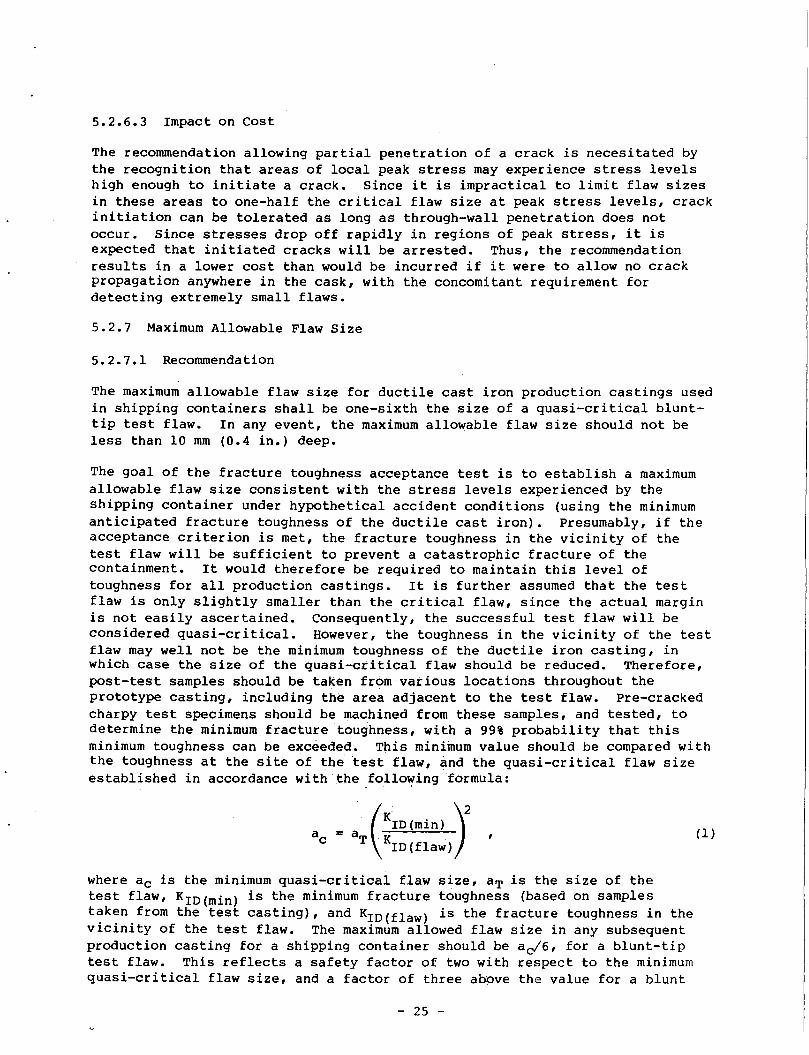
The recommendation allowing partial penetration of a crack is necesitated by the recognition that areas of local peak stress may experience stress levels high enough to initiate a crack. Since it is impractical to limit flaw sizes in these areas to one-half the critical flaw size at peak stress levels, crack initiation can be tolerated as long as through-wall penetration does not occur. Since stresses drop off rapidly in regions of peak stress, it is expected that initiated cracks will be arrested. Thus, the recommendation results in a lower cost than would be incurred if it were to allow no crack Propagation anywhere in the cask, with the concomitant requirement for detecting extremely small flaws.
5 .2 .7 Maximum Allowable Flaw Size
5.2.7.1 Recommendation
The maximum allowable flaw size for ductile cast iron production castings used in shipping containers shall be one-sixth the size of a quasi-critical blunt- tip test flaw. less than 10 mm (0.4 in.) deep.
In any event, the maximum allowable flaw size should not be
The goal of the fracture toughness acceptance test is to establish a maximum allowable flaw size consistent with the stress levels experienced by the shipping container under hypothetical accident conditions (using the minimum anticipated fracture toughness of the ductile cast iron). Presumably, if the acceptance criterion is met, the fracture toughness in the vicinity of the test flaw will be sufficient to prevent a catastrophic fracture of the containment. It would therefore be required to maintain this level of toughness for all production castings. It is further assumed that the test flaw is only slightly smaller than the critical flaw, since the actual margin is not easily ascertained. Consequently, the successful test flaw will be considered quasi-critical. flaw may well not be the minimum toughness of the ductile iron casting, in which case the size of the quasi-critical flaw should be reduced. Therefore, post-test samples should be taken from various locations throughout the prototype casting, including the area adjacent to the test flaw. Pre-cracked charpy test specimens should be machined from these samples, and tested, to determine the minimum fracture toughness, with a 99% probability that this minimum toughness can be exceeded. the toughness at the site of the test flaw, and the quasi-critical flaw size established in accordance with the following formula:
However, the toughness in the vicinity of the test
This minimum value should be compared with
where a, is the minimum quasi-critical flaw size, aT is the size of the test flaw, KID(min) is the minimum fracture toughness (based on samples taken from the test casting), and KID(flaw) is the fracture toughness in the vicinity of the test flaw. The maximum allowed flaw size in any subsequent production casting for a shipping container should be aJ6, for a blunt-tip test flaw. This reflects a safety factor of two with respect to the minimum quasi-critical flaw size, and a factor of three above the value for a blunt
- 25 -

crack developing the same fracture toughness stress intensity as a sharp crack (see Appendix B) . 5.2.7.2 Impact on Safety
The thrust of this recommendation is to provide an acceptable margin of safety against brittle fracture due to the presence of flaws. flaws is the same as that recommended in Section XI of the ASME Boiler and Pressure Vessel Code (Section IWB-3611). For blunt-tip flaws, the fracture toughness stress intensity developed is at most l/d3 that of a sharp-tip flaw, which translates into a critical flaw size three times that of a sharp- tip flaw under similar conditions of geometry and loading. reduction to one-sixth of the blunt-tip quasi-critical test flaw size assures a safety margin equivalent to that for a sharp-tip flaw.
The factor of 1/2 for
Consequently, a
The procedure for establishing the quasi-critical flaw size ensures that it is based upon the minimum fracture toughness of the ductile cast iron likely to be encountered throughout any one production casting. It also takes into account the probability that the fracture toughness at the test flaw location is not necessarily the minimum fracture toughness of the ductile iron casting.
5.2.7.3 Impact on Cost
The impact of this recommendation is ultimately reflected in the establishment of a maximum allowable flaw size, which will have to be detected by inspection. derived for the fracture toughness stress intensity, much larger Lest flaws must be introduced to compensate for this difference. flawqs size is judiciously chosen, there should be no difference in the maximum allowable flaw specified either by this test or by the use of a sharp-tip test flaw. Furthermore, if the variation of fracture toughness throughout the cask is small, then the inspection limit will be close to that anticipated by the test flaw. variation is large, the inspection limit may be too rigorous for conventional NDE procedures. If the latter condition is expected, it would be prudent for the applicant to increase the size of the test flaw to preclude inspection difficulties. (0 .4 in.) assures detection with state-of-the-art methods.
Since a blunt-tip test flaw results in a lower value being
If the blunt-tip test
On the other hand, if the fracture toughness
Specifying a maximum allowable flaw size of not less than 10 mm
The recommended method for measuring the fracture toughness of ductile cast iron in qualifying it for acceptance is the pre-cracked charpy impact
those obtained from standard specimens (as recommended in ASME-399). However, this is not detrimental to the application considered here, since the fracture toughness values are not intended for design use. They are, rather, used in a comparative sense: either the toughness at the location of a flaw is compared to the minimum toughness obtained by the same method, or the toughness of a cast-on (or separately cast) test block is compared to its associated casting or to test blocks representing other castings. Thus, having a standard value for fracture toughness is less important than being able to apply a familiar, consistent, and cost-effective testing method. A further advantage of taking pre-crack charpy test data is that they are translatable into flaw sizes using linear elastic fracture-mechanics formulas, so that relative measures of flaw sizes can be established.
The values indicated by this test are not as authoritative as
- 26 -

REFERENCES
1. M. W. Schwartz, and Boyce, L., "Ductile and Brittle Failure Design Criteria for Nodular Cast Iron Spent Fuel Shipping Containers," Lawrence Livermore National Laboratory, Livermore, Calif., UCRL-53046, March 1983.
2. Boiler and Pressure Vessel Code, Section 111, NB-3200 "Design By Analysis," Am. SOC. of Mech. Engineers, (1980).
3. "Pressure Vessel Codes: Their Application to Nuclear Reactor Systems," Technical Reports Series No. 56, International Atomic Energy Agency, Vienna, 1966.
4 . W. L. Server, "Impact Three-Point Testing for Notched and Pre-Cracked Specimens," Journal of Testinq and Evaluation, 6(1), ASTM, Philadelphia, Penna., 1978.
5 . "Proposed Standard Method of Test for Instrumented Impact Testing of Pre-Cracked Charpy Specimens of Metallic Materials," ASTM E-24.03.03, April 1980.
6. M. Creager, and Paris, P. C., "Elastic Field Equations for Blunt Cracks with Reference to Stress Corrosion Cracking."
- 27 -

APPENDIX A RADIOLOGICAL RISK OF A CRACK IN A DUCTILE CAST IRON CASK
1. INTRODUCTION
This appendix presents a conservative estimate of the effect on the gamma dose that a crack would have, if it penetrated three-quarters of the way through the cask wall. attenuation were assumed. The projected dose will be most intense along the plane of the crack and will drop off rapidly in a direction normal to this plane, as the effect of the full shield comes into play. The crack can therefore be modeled as an isotropic line source emitting into the half space and the intensity should decrease with distance in accordance with 1/2ar.
Uniformly distributed point sources and line-of-sight
2. CRACK CONFIGURATION
A semi-elliptical configuration is assumed for the crack, in a plane normal to the cask's axis, as shown in Fig. A-1. The crack's thickness is assumed to be no greater than 0.1 in. (2.5 mm), but the dose rates are also estimated for smaller widths.
3 . ASSUMPTIONS ABOUT THE SOURCE TERM
(1) 16 BWR assemblies, with 3.36 MTU per cask. (2) 35 MW specific power. (3) 25 000 MWD burnup. ( 4 ) One year post-irradiation time. (5) Spacific activities. (6) Gamma energies and branching ratios from GAMANAL MLIB and Lederer's
Table of the Isotopes.
Table A-1 summarizes the source-term specific activities in Ci/MTU, along with the major gamma energies and their associated branching ratios. (Gammas with branching rrtios of less than 0.05 were not included.) Table A-2 summarizes the source terms for the full cask in terms of photons/second. Also included are the linear attenuation coefficients for iron vs the gamma energy.
- 28 -

- - . . . - ... ... . . - . -
Figure A-1. Simplified cross section of a d u c t i l e cast iron cask, w i t h a c r a c k 12-in. (30.48-cm) d e e p and a 36-in. (91.44-cm) h a l f wid th .
L
Gap Width of F r o n t a l A r e a of D i a m e t e r of a C i r c l e w i t h t h e C r a c k t h e C r a c k a n Area E q u i v a l e n t to t h e i n . ( c m ) i n . 2 (cm2) F r o n t a l Area of t h e Crack
i n . ( c m )
0.02 (0.05) 0.04 (0.10) 0.06 (0.15) 0.08 (0.20) 0.10 (0.25)
1.44 (9.29) 2.88 (18.58) 4.32 (27.87) 5.76 (37.16) 7.20 (46.45)
1.35 (3.43) 1 .91 (4.85) 2.35 (5.97) 2.71 (6.88) 3.03 (7.70)
- 29 -

Table A-1. Major fission product activities and characteristics at one year post-irradiation; specific power: 35 MW, burnup: 25 000 MWD.
P _r_cI - Half-Life Specific Activity Major Gamma Energy (Branching Ratio)
Isotope (Days) (Ci/MTU) ( KeV)
1761 (0.000006)
1761 (0.000006)
1205 (0.0022)
4
4
4
10 526.5 6.24 x 10
2.67 6.24 x 10
58.8 1.64 x 10
65.0 3.51 lo4 724 (0.43), 757 (0.546)
35.1 7.42 x 10
366.5 2.10 x 10
0.00035 2.10 x 10
0.00028 2.05 104 658 (0.945), 678 (0.105), 687 (0.0641, 707 (0.167), 764 (0.223), 818 (0.073),
1384 (0.242), 1505 (0.130)
90s,
91Y
9 5 ~ r
95Nb 766 (0.99) 4
5
5
512 (0.205), 622 (0.098) lO6RU
512 (0.205), 622 (0.098) lo Rh
885 (0.726), 937 (0.343)r
134cs 745.0 1.16 105 563 (0.084), 569 (0.154), 605 (0.9761, 796 (0.160), 802 (0.087)
662 (0.85)
662 (0.85)
134 (0.11)
697 (0.0133)
122 (0.00003)
4
4
5
5
4
10 960.0 8.13 x 10
0.0018 7.69 x 10
284.0 4.80 x 10
0.012 4.80 x 10
147- 958.2 8.73 x 10
137cs
137Ba
l4 ~e
144Pr
- 30 -

Table A-2. Source characteristics €or a full cask (16 assemblies) at one year.
Iron Attenuation Coefficient * , u i Gamma Energy, (Ei) Source Strength (keW (Photons/s ) (cml I
122
134
51 2
563
569
605
622
658
662
678
687
697
707
724
757
764
766
796
802
818
885
937
1205
1384
1505
1761
11
15
16
15
15
16
15
15
16
14
14
14
14
15
15
15
15 15
15
14
15
14
12
14
14
10
3.26 x 10
6.56 x 10 1.07 x 10
1.21 x 10
2.22 x 10 1.41 x 10
5.12 x 10 2.41 x 10
1.67 x 10
2.68 x 10
1.63 x 10
7.94 x 10 4.26 x 10
1.88 x 10
2.38 x 10
2.55 x 10 9.13 x 10
1.23 x 10 1.25 x 10
1.86 x 10
1.85 x 10
8.74 x 10 4.49 x 10
6.17 x 10 3.31 x 10
4.65 x 10
2.052
1.795
0.655
0.625
0.622
0.604
0.596
0.579
0.578
0.571
0.567
0.563
0.559
0.553
0.541
0.539
0.538
0.532
0.526
0.521
0.502
0.487
0.429
0.400
0.383
0.351
16 Total 8.30 x 10
* From Howerton
- 31 -

4. ASSUMPTIONS MADE ABOUT THE SHIELD
(1) ( 2 )
(3 ) ( 4 ) (5 )
P o i n t s o u r c e ( l i n e - o f - s i g h t a t t e n u a t i o n ) . The source s t r e n g t h s are d i s t r i b u t e d uniformly, and are p r o p o r t i o n a l t o area. Buildup is based on t h e s o u r c e - s t r e n g t h weighted energy. The crack d e p t h is uniform to 12 i n . (30.48 Cm)
The a t t e n u a t i o n i n a i r is n e g l e c t e d .
For a f u l l s h i e l d , f s , w i t h t h e s o u r c e term d i s t r i b u t e d uniformly a b o u t t h e s u r f a c e of a r i g h t c i rcu lar c y l i n d e r having a 13-in. h e i g h t o f 179.5 in . (4.56 m ) , we have:
(33-cm) r a d i u s and a
and
where:
$ f s (16) = t h e p o i n t s o u r c e f l u x a t 1 6 in . (40.64 c m ) f o r t h e f u l l s h i e l d , i n photons/cm2s
= t h e t o t a l Source s t r e n g t h f o r t h e i t h gamma-ray ene rgy , i n
= 1 6 i n . (40.64 c m ) o f iron, i n c m = 2prh = 1 4 665 i n . 2 (94 549 cm2) = p o i n t s o u r c e s t r e n g t h per u n i t area f o r t h e ith g a m a r a y
i pho tons / s ST
t16 Acy 1 S i
energy, i n photons/cm2s.
For t h e cracked s h i e l d , cs, a un i fo rmly d i s t r i b u t e d s o u r c e w i t h a n area e q u a l t o t h e crack f r o n t a l area, b, is assumed for t h e reduced a t t e n u a t i o n e f f e c t . Thus, we write t h e f l u x as:
(A-3)
$cs(16) = t h e p o i n t s o u r c e f l u x a t 1 6 i n . (40.64 c m ) f o r t h e
t 4 = 4 i n . (10.16 c m ) of i r o n , i n cm. c r acked s h i e l d , i n photons/cm2s
S u b s t i t u t i n g for si from Eq. ( ~ - 2 ) ~ w e have:
(A-4)
- 32 -

Solving for the relative effect of the crack, we have:
The results of the attenuation calculations of Eq. (A-5) are summarized in Table A-3. The summation results are:
= 2.35 x photons/s , f s e-pit4 1 Ti
and
8 26 t -" l6 = 1.24 x 10 photons/s .
- 33 -
(A-5)
(A-6)
(A-7)

Table A-3. A t t e n u a t i o n resul ts f o r 16-in. (40.64-cm) and 4-in. (10.16-cm) t h i c k n e s s e s o f i r o n .
-'iK16 S e Ti Gamma Energy,
- 'it4 S e Ti
( k e w (Photons/s) (Photons/s)
1 2 2
134
51 2
563
569
605
622
658
678
687
662
697
707
724
757
764
766
796
a02
818
885
937
1205
1384
1505
1761
1.98 x 1.37 x
2.94 x 1 0
1.13 x 1 0
2.33 x 1 0
4
4
4
5
5
5
6
3.08 x i o 1 .55 x 1 0
1.45 x 1 0
1.05 x 1 0 2.24 l o 4
4
4
4
5
5
5
6
1.60 x 1 0
9.18 x 1 0
5.80 x i o 3.26 x 1 0
6.73 x 1 0
7.82 x i o 2.92 x 1 0
5.01 l o 5 5 6.50 x 10 5 1.19 x 1 0 6 2.55 x 1 0
2.22 x 1 0 6
5 1.20 x 1 0 7
7 5.38 x i o
2.97 l o 7 5.75 x 1 0
T o t a l a 1.24 x 1 0
2.88 x ioL 7.88 x lo7
1.38 x i o 1 3
12 2.11 x 10 1 2
1 3 4.00 x 10
3.05 x 1 0 1 3 1.20 x 1 0
6.72 x 1 0 l 2
4.70 8.10 x io11
11 5.13 x 1 0
2.60 x 1 0 l 2 1 2
12
1 2
1 3
1 3
1.45 x 1 0
6.82 x i o 9.76 x 1 0
1.07 x 1 0
3.86 x i o 5.53 x 10l2 5.97 x 10l2 9.35 x l o l l
1 3 1.13 x 1 0
6.20 x 1 0 l 2 1 0 5.75 x 1 0 1 3 1.06 x 10 1 2 6.76 x 10
1 .31 l o 9
1 4 2.35 x 1 0
- - 34 -
I.

To estimate t h e dose bui ldup , t h e Taylor e q u a t i o n w a s used by assuming a s i n g l e i n c i d e n t photon energy , weighted by t h e s o u r c e s t r e n g t h . u s ing t h e data from Table A-2, it can be shown t h a t t h e weighted energy is 625 KeV and t h e l i n e a r a t t e n t u a t i o n c o e f f i c i e n t , p, is e q u a l to 0.595 c m - l . According to Tay lo r , t h e dose bu i ldup is g i v e n by:
I n t h e case of i r o n and an energy , E, o f 625 KeV: A = 9.5, a = 0.0935, and B = 0.019. S u b s t i t u t i n g f o r A, a, and B i n Eq. ( A - 8 ) , w e o b t a i n :
and
S u b s t i t u t i n g Eqs. (A-6) and (A-7) i n t o Eq. (A-5), and a l lowing f o r t h e estimate o f dose bu i ldup , w e have:
1 4
8 4cs (16) Ac (2.35 x 1 0 ) (9.07)
$ f s (16) A c y 1 (1.24 x 1 0 ) (85.9) = -
S u b s t i t u t i n g f o r t h e area of t h e c y l i n d e r and s o l v i n g , we o b t a i n :
(A-9)
(A -10 )
(A-11)
(A-1 2 )
For t h e crack t h i c k n e s s e s under c o n s i d e r a t i o n , w e have c a l c u l a t e d t h e v a l u e s shown i n Table A-4.
Table A-4. R e l a t i v e e f f e c t of a crack.
C r a c k T h i c k n e s s Frontal A r e a
i n . ( c m ) ( c m 2 ) $O(W/c!f,(16)
0.02 (0.05) 9.29
0.04 (0.10) 18.58
0.06 (0.15) 27.87
0.08 (0.20) 37.16
0.10 (0.25) 46.45
19.66
39.32
58.97
78.63
98.29
- 35 -

Consider ing t h e p r o p o r t i o n a l i t y of f l u x t o dose , and t h e c a l c u l a t e d gamma s u r f a c e dose ra te a t t h e cask's s i d e (6.5 mrem/hr), w e have:
(A-13)
and can d e r i v e t h e e s t i m a t e d dose ra te a t t h e s u r f a c e above several cracks of
v a r i o u s wid ths , as shown i n Table A-5.
Table A-5. Es t imated s u r f a c e dose rate a t cracks.
C r ' a c k ' Thickness Dcs(16) i n . ( c m ) (mrem/h)
0.02 (0.05) 128
0.04 (0.10) 255
0.06 (0.15) 383
0.08 (0.20) 511
0.10 (0.25) 639
I f w e assume t h a t t h e dose bu i ldup i n t h e cracked s h i e l d can be n e g l e c t e d -- a r e a s o n a b l e approach , since any u n c o l l i d e d photon t h a t p e n e t r a t e s t h e 4- in . (10.2-cm) t h i c k i r o n s h i e l d and is t h e n s c a t t e r e d o u t of t h e narrow beam w i l l l i k e l y be lost -- t h e r e su l t s of Table A-4 and A-5 w i l l be reduced by a f a c t o r of 9.07. Thus, t h e r e l a t ive e f f e c t o f t h e crack f o r t h e maximum crack t h i c k n e s s w i l l be ~ 1 1 t i m e s g r e a t e r t h a n t h e dose rate a t t h e s u r f a c e of t h e c a s k . I f w? assume a 6.5 mrem/h gamma dose ra te a t t h e s u r f a c e , t h e n t h e dose a t t h e crack would be on t h e o r d e r of 70 mrem/h.
- 36 -

APPENDIX B FRACTURE TOUGHNESS STRESS INTENSITIES FOR BLUNT-TIP CRACKS
Mathematically, a blunt crack is conveniently represented by an elliptical cylinder that is void of material and has a small tip radius, compared to the crack's length. under these circumstances the configuration of the crack tip is nearly parabolic, as shown in Fig. A-1, with the focus at a distance of p/2 from the crack tip, where p is the crack tip's radius. This geometric idealization makes it possible to develop a set of field equations for the vicinity of the blunt-crack's tip, which are similar to those for a sharp crack. For the opening mode I, these are:6
The stress-state relations differ from those of the ideal sharp crack only by the addition of a second term, which is dependent upon the radius of curvature of the tip. For distances from the crack tip where p/r + 0, the field equations revert to those of the ideal sharp crack and they are perturbed for mode-I loading only in the immediate vicinity of the blunt-crack's tip.
The stresses in the plane of the crack are:
and
= o . XY T
Furthermore, at the surface of the crack in the crack plane, uX = 0 and r = p/2, so that:
(B-2a)
(B-2b)
(B-2C)
- 37 -

t
F i g u r e B-1. C o o r d i n a t e s of a b l u n t crack t i p .
A t t h e s u r f a c e of t h e b l u n t crack, i n t h e crack p l a n e , ax = 0, so t h a t :
a ( e = o , r = , ) = = , P 2KI Y
where = 0, r = p/2) is t h e maximum stress a t t h e s u r f a c e of t h e b l u n t crack. The q u a n t i t y , 0 , decreases w i t h a n i n c r e a s e i n r , as shown i n Fig. B-2. Y
F i g u r e B-2. S t r e s s a t a b l u n t crack prior to y i e l d .
- 38 -

.. - . . .. ... . . . .... - - - .. - - -
-
For a n ideal sharp crack, w i t h its t i p a t t h e o r i g i n of t h e b lun t - c rack
coordinate system, t h e d i s t r i b u t i o n for 0 is: * Y
PI2 0-
* * KI Y G ' u ( e = 0) = -
* where symbolizes parameters associated w i t h a n ideal sharp crack. I n
Fig. B-3, t h e stress d i s t r i b u t i o n f o r ay is shown superimposed on t h e b l u n t - c r a c k ' s stress d i s t r i b u t i o n . Note t h a t if:
*
* * K I = K I , aY = oY/2 a t r = p/2 .
7 Stress at the surface
F i g u r e B-3. Comparison of t h e stress d i s t r i b u t i o n between a sharp crack and a b l u n t crack.
* If ideal e l a s t i c i t y is assumed, v e r y l o w v a l u e s of K I c a n c a u s e a s h a r p crack to become u n s t a b l e . However, i n t h e case of real metals, a p las t ic zone forms a t t h e t i p of t h e s h a r p crack, which t e n d s t o i n c r e a s e t h e c r i t i c a l
stress i n t e n s i t y , KIc.
p l a s t i c - z o n e s i z e , R, e q u a l s ,,/2, as shown i n F ig . 8-4: ay a t
t h e n t h e y i e l d stress Q s. stress i n t e n s i t y f o r t h g sharp crack is:
* * Suppose KI i n c r e a s e s to a p o i n t where t h e *
is *
The r e l a t i o n of t h e p l a s t i c - z o n e ' s s i z e to t h e
- 39 - I

* where KIY i s t h e s t ress i n t e n s i t y r e q u i r e d to deve lop a p l a s t i c zone, R = p/2. y i e l d i n g is r e l a t e d to t h e y i e l d stress by Eq.
The s t r e s s i n t e n s i t y r e q u i r e d for t h e b l u n t crack t o s t a r t ( B - 3 ) :
2K I Y 9
=ys = 3T S u b s t i t u t i n g Eq. (B-6) i n t o Eq. (B-5) g i v e s :
* K
K I Y
I Y - = fi.
I Blunt crack 1
9 R = p / 2
F i g u r e B-4. T h e ' p l a s t i c zone a t t h e t i p of a s h a r p crack.
- 40 -

Thus, t h e stress i n t e n s i t y t h a t j u s t i n i t i a t e s y i e l d a t t h e b l u n t crack's s u r f a c e is 1 /&of t h e stress i n t e n s i t y r e q u i r e d t o deve lop a p las t ic zone a t t h e s h a r p crack, such t h a t t h e y i e l d stress p r e v a i l s a t p/2. I f it is assumed t h a t t h e s h a r p crack is n o t y e t c r i t i ca l when R = p/2, t h e n t h e
b l u n t crack is c e r t a i n l y n o t c r i t i ca l when KIy = K I y / n . What w e need t o know, however, is what K~~ would be when t h e plast ic zone of t h e s h a r p crack i s l a r g e enough to c a u s e crack i n s t a b i l i t y , i.e., when R = R f . For t h e s h a r p crack:
*
T h i s r e l a t i o n s h i p is shown i n Fig. B-5.
t
-I Blunt c r a c k 1
F i g u r e B-5. A sharp crack 's p las t ic zone a t i n s t a b i l i t y .
I n becoming cr i t ical , t h e plast ic zone i n c r e a s e s i n s i z e from R = p/2 to R f . A t the same t i m e , it is s t a r t i n g from a y i e l d c o n d i t i o n (as shown i n F ig . B-6).
a plastic zone d e v e l o p s a t t h e t i p of t h e b l u n t crack s i n c e
- 41 -

Figure B-6. The b lunt c r a c k ' s p l a s t i c zone when t h e sharp crack is u n s t a b l e .
If KIB is t h e stress i n t e n s i t y a s s o c i a t e d wi th t h e b lunt Crack when t h e s t r e s s i n t e n s i t y of t h e sharp crack is c r i t i c a l , then for t h e b l u n t Crack, w e can see t h a t :
OK
S i m p l i f y i n g Eq. (B-10) g i v e s :
2
(.*IC) -(.:,)*
(B-10)
- 4 2 -

2 Divid ing both s i d e s by (KIB) g i v e s :
or
then I Y
S i n c e K~~ > K
O r , from Eq. (B-7)
* * K K
K K I B
Iy<- I Y
I Y
* K I y < fi , K I B
so, as a consequence:
and
* < I T . KIc
K I B 1 < -
T h e r e f o r e , t h e s i z e t h a t a b l u n t crack would have to be, i n o r d e r t o deve lop a c r i t i c a l s t ress i n t e n s i t y e q u i v a l e n t t o t h a t o f a n i d e a l s h a r p crack, is i n t h e range:
C a
a 1 < . < 3 .
C
The complex c o n d i t i o n s a t t h e crack 's t i p make it d i f f i c u l t to e s t a b l i s h a p r e c i s e r e l a t i o n s h i p between t h e behavior of s h a r p and b l u n t cracks. N o doubt t h e s h a r p crack takes on b l u n t - l i k e c h a r a c t e r i s t i c s when t h e p l a s t i c zone develops . However, w e c a n c o n f i d e n t l y s t a t e t h a t , under similar load ing c o n d i t i o n s , a s h a r p crack w i l l become u n s t a b l e b e f o r e a b l u n t c r a c k (i.e.,
KIc/KIB > 1); whi l e , on t h e b a s i s of wide ly accep ted r e l a t i o n s h i p s
between s t ress i n t e n s i t y and p las t ic zone s i z e , K ~ ~ / K ~ ~ < 3 . p r e c i s e r a t i o canno t be e a s i l y a s c e r t a i n e d , e x c e p t pe rhaps by t e s t i n g , p rudence d i c t a t e s u s ing t h e upper bound.
* *
S i n c e a
- 43 -