recent progress in electrical generators for oceanic wave
TRANSCRIPT

University of Wollongong University of Wollongong
Research Online Research Online
Faculty of Engineering and Information Sciences - Papers: Part B
Faculty of Engineering and Information Sciences
2020
Recent Progress in Electrical Generators for Oceanic Wave Energy Recent Progress in Electrical Generators for Oceanic Wave Energy
Conversion Conversion
Abidur Rahman
Omar Farrok
Md Rabiul Islam University of Wollongong, [email protected]
Wei Xu [email protected]
Follow this and additional works at: https://ro.uow.edu.au/eispapers1
Part of the Engineering Commons, and the Science and Technology Studies Commons
Recommended Citation Recommended Citation Rahman, Abidur; Farrok, Omar; Islam, Md Rabiul; and Xu, Wei, "Recent Progress in Electrical Generators for Oceanic Wave Energy Conversion" (2020). Faculty of Engineering and Information Sciences - Papers: Part B. 4273. https://ro.uow.edu.au/eispapers1/4273
Research Online is the open access institutional repository for the University of Wollongong. For further information contact the UOW Library: [email protected]
Recent Progress in Electrical Generators for Oceanic Wave Energy Conversion Recent Progress in Electrical Generators for Oceanic Wave Energy Conversion
Abstract Abstract Oceanic wave energy extraction through electrical generator is one of the most interesting topics in the field of power engineering. Almost all the existing relevant review paper focus on electrical generator with the working principle of electromagnetic induction or piezoelectric or triboelectric effect. In this paper, all the existing types (based on principle of operation) of electrical generator used for wave power harvesting are discussed. This paper not only covers recent progress in electrical power generation by electro-magnetic induction, piezoelectric generator, and electrostatic induction, but also presents critical comparative review as well where suitable use and weakness of each type of generators are discussed. Moreover, the application of advanced magnetic core, winding, and permanent magnets are discussed with extensive explanation which are not focused in the existing reviews. Various new constructional features of the electrical generators such as split translator flux switching, two-point absorber, triangular coil, dual port linear generator, piezoelectric, triboelectric nanogenerator, etc. are highlighted with principles of operation. It also includes emerging human intervened optimization method for determining optimum shape of generator and cooling system which is necessary to prevent demagnetization of the permanent magnet. Finally, the way of supply the generated electrical power form the generator to load/grid is thoroughly described in a separate section that would be obvious for successful operation. The comparison among all types of generators in terms of output voltage, current, scale of power production, power-frequency characteristics, power density, cascading, and approaches are tabulated in this paper.
Keywords Keywords progress, electrical, generators, oceanic, wave, energy, recent, conversion
Disciplines Disciplines Engineering | Science and Technology Studies
Publication Details Publication Details A. Rahman, O. Farrok, M. Islam & W. Xu, "Recent Progress in Electrical Generators for Oceanic Wave Energy Conversion," IEEE Access, vol. Online First, p. 1, 2020.
This journal article is available at Research Online: https://ro.uow.edu.au/eispapers1/4273

This work is licensed under a Creative Commons Attribution 4.0 License. For more information, see https://creativecommons.org/licenses/by/4.0/.
This article has been accepted for publication in a future issue of this journal, but has not been fully edited. Content may change prior to final publication. Citation information: DOI10.1109/ACCESS.2020.3012662, IEEE Access
VOLUME XX, 2017
Date of publication xxxx 00, 0000, date of current version xxxx 00, 0000.
Digital Object Identifier 10.1109/ACCESS.2020. Doi Number
Recent Progress in Electrical Generators for Oceanic Wave Energy Conversion
Abidur Rahman1, Omar Farrok1, Md. Rabiul Islam2, and Wei Xu3 1Department of Electrical and Electronic Engineering, Ahsanullah University of Science and Technology, Dhaka-1208, Bangladesh; [email protected]; [email protected], [email protected] 2School of Electrical Computer and Telecommunications Engineering, University of Wollongong, Wollongong, Australia; [email protected] 3State Key Laboratory of Advanced Electromagnetic Engineering and Technology, School of Electrical and Electronic Engineering, Huazhong University of Science and Technology, Wuhan, 430074, China; [email protected]
Corresponding author: Wei Xu (e-mail: [email protected]).
This work was supported in part by the National Natural Science Foundation of China under Grants 51877093.
ABSTRACT Oceanic wave energy extraction through electrical generator is one of the most interesting
topics in the field of power engineering. Almost all the existing relevant review paper focus on electrical
generator with the working principle of electromagnetic induction or piezoelectric or triboelectric effect. In
this paper, all the existing types (based on principle of operation) of electrical generator used for wave power
harvesting are discussed. This paper not only covers recent progress in electrical power generation by electro-
magnetic induction, piezoelectric generator, and electrostatic induction, but also presents critical comparative
review as well where suitable use and weakness of each type of generators are discussed. Moreover, the
application of advanced magnetic core, winding, and permanent magnets are discussed with extensive
explanation which are not focused in the existing reviews. Various new constructional features of the
electrical generators such as split translator flux switching, two-point absorber, triangular coil, dual port linear
generator, piezoelectric, triboelectric nanogenerator, etc. are highlighted with principles of operation. It also
includes emerging human intervened optimization method for determining optimum shape of generator and
cooling system which is necessary to prevent demagnetization of the permanent magnet. Finally, the way of
supply the generated electrical power form the generator to load/grid is thoroughly described in a separate
section that would be obvious for successful operation. The comparison among all types of generators in
terms of output voltage, current, scale of power production, power-frequency characteristics, power density,
cascading, and approaches are tabulated in this paper.
INDEX TERMS electrostatic induction generator; linear electrical generator; magnetic material;
optimization; permanent magnet; piezoelectric generator, superconductor; wave energy converter.
NOMENCLATURE DPLG Dual port linear generator LG Linear generator
EFHAS Elastic floating unit with hanging structure M-27 DI MAX M-27
EMG Electromagnetic generators NdFeB Neodymium iron boron
FPED Flexible piezoelectric device OWE Oceanic wave energy
HF-10 DI MAX HF-10 PMLG Permanent magnet linear generator
HF-10X DI MAX HF-10X RES Renewable energy source
HF-12 DI MAX HF-12 TENG Triboelectric nanogenerator
HIGA Human intervened genetic algorithm WEC Wave energy converters
HTS High temperature superconductors YBCO Yttrium barium copper oxide
I. INTRODUCTION
With technological advancements and increasing human
population, the demand for electrical energy is growing
precipitously. To facilitate the demand of electricity at global
scale, the electrical power generating capacity must be
increased. At present, most electrical generators rely greatly

This work is licensed under a Creative Commons Attribution 4.0 License. For more information, see https://creativecommons.org/licenses/by/4.0/.
This article has been accepted for publication in a future issue of this journal, but has not been fully edited. Content may change prior to final publication. Citation information: DOI10.1109/ACCESS.2020.3012662, IEEE Access
2
on fossil fuels. It is a fact that fossil fuels such as coal,
petroleum, and gasoline are non-renewable energy sources
and are diminishing at a rapid rate. These sources emit carbon
dioxide and other greenhouse gases which are detrimental to
the nature. Forecasted results demonstrate that by the end of
this century the average temperature of the earth surface would
rise by 1.4–5.8°C. Moreover, the warming rate is expected to
be 0.02°C per annum based on recent decades [1]. The
consequences caused by carbon emissions will primarily be
observed near the coastal areas due to the rise of sea water
level. Moreover, small islands may completely be flooded if
this issue is not addressed. Scientists and researchers have
investigated for many years to find a replacement of fossil
fuels to lessen the impact on environment. Renewable energy
source (RES) such as solar, wind, hydropower, biomass, and
geothermal are used as an alternative to conventional fuels
since they are widely available and cause little to no harm to
nature.
The total power generating capacity of different RESs are
presented in Fig. 1 [2]. RESs such as hydro, wind, and solar
have the highest capacity compared to others as vast research
is conducted in these fields since many years. Extensive
research on solar, wind, and hydropower enables us to harness
large amount of energy through these. On the other hand,
oceanic wave energy (OWE) retains considerable amount of
energy yet its installed capacity is infinitesimal as compared to
other RESs.
FIGURE 1. Electrical power generated from various RESs.
Many RESs such as wind and solar has large installed capacity
but are intermittent in nature. Generation through wind energy
relies on the availability and direction of wind speed. As for
solar energy, solar radiation is required which depends on
diurnal period and weather condition. Hence, sophisticated
energy storage device is essential to mitigate the issue of
power discontinuity. There are other RESs such as geothermal
and hydropower plants which can only be implemented in few
areas throughout the world because of their lack of
availability. On the other hand, OWE is readily available in the
ocean and it is not site specific which makes it a desirable
preference over many other RESs. Moreover, the energy
density of OWE is commendable.
Electricity generation through OWE was first proposed in
the late 18th century. OWE has been considering one of the
potential RESs in many countries since 1973, due to the oil
crisis. Around 1–10TW of electrical power can be extracted
from oceanic waves which could serve a significant amount of
the world’s electrical power demand. Wave energy greatly
depends on different factors such as magnitude, frequency,
wavelength, distance from the shorelines etc. Given the
location of oceanic waves such as near shore, offshore or
shorelines, approximately 50–100kW power per meter of
wave front could be generated [3].
UK, US, Japan, India, Australia and many other countries
have adopted the OWE converters to serve their energy
demand [4]. EU aims to fulfill all its energy demand through
RESs out of which approximately 0.02% of energy is currently
delivered by OWE. The leading nation, focusing on OWE, UK
aims to fulfill 20% of their total demand from OWE by 2020.
Ireland has set a goal to produce 0.5GW power through OWE
by 2020 [5]. In Scotland, a wave energy project is installed
which can produce 150kW of power [6]. The expected wave
power in Europe is approximately 20–60kW/m. Around
1170TWh/year of energy can be harvested from OWE [7]. The
nearshore OWE of China is nearly 249.7TWh/year [8].
Approximately 50TWh/year of OWE is acquired by UK [9].
Oceanic wave creates mechanical movement in wave
energy harvesting devices. Waves are random in nature that
affects wave energy devices. These devices are namely Wave
Dragon, Pelamis, Limpet, Archimedes wave swing, etc. The
random mechanical movements are not rotational. However,
with the aid of auxiliary devices, the random motion can be
converted into stable rotational movement. But considering
the monetary cost, energy loss, and complex maintenance, the
auxiliary devices are subjected to further assessment. Hence
traditional devices are not suitable to harvest wave energies.
Special type of device along with generator are required to
convert the mechanical movements into electrical energy.
Majority of these generators are linear generators (LGs)
operated by the principle of electromagnetic induction.
Recently, small scale piezoelectric and triboelectric generators
are tested for this purpose. Energy extraction from OWE is still
at its initial stage and extensive research is required to become
fruitful as wind and solar power plants.
Floating point observes are modeled in [10] through
numerical methods, such as empirical method, Navier-Stokes
equation, and boundary integral equation. However, the
review does not discuss about connecting these generators
with the grid. Moreover, other types of wave energy converter
are not modeled. In [2], different wave energy conversion
techniques are introduced for electromagnetic and
piezoelectric generators. Moreover, the review also discusses
about different wave energy converters such as point absorber,
overtopping device, oscillating water column. Finally, various
control scheme is shown to regulate the output from these
devices. Nevertheless, triboelectric generators are not
considered in the review. Moreover, sustainable operating
environment for different type of generator is not explained.
Recent improvement in the field of piezoelectric material-
based energy harvester is discussed in [11]. Energy harvesting
characteristics of different types of piezoelectric devices are
illustrated. Various electronic circuits required to operate the

This work is licensed under a Creative Commons Attribution 4.0 License. For more information, see https://creativecommons.org/licenses/by/4.0/.
This article has been accepted for publication in a future issue of this journal, but has not been fully edited. Content may change prior to final publication. Citation information: DOI10.1109/ACCESS.2020.3012662, IEEE Access
3
piezoelectric devices are showed in this review. However, no
discussion has been made on other type of wave energy
harvesters such as electromagnetic generators or triboelectric
nanogenerators. Moreover, these reviews do not provide
adequate guidelines for grid connectivity with the generators.
Electrostatic generators can be considered useful for
harnessing energy from ocean, especially for low frequency
waves. Current progress of this technology is reviewed in [12]
where various types of energy harvesting devices with
electrostatic generators are presented. However, detailed
analysis of suitable operating condition is not described.
Application of advanced material for different electrical
generator is not presented. The review mentioned the necessity
of grid connection, but not presented at all and left in the future
scope.
However, to the best of authors’ knowledge, no review is
found that delineates on the recent development of electrical
generators, their critical review, and aggregation or grid
connection for oceanic wave energy extraction together. In this
context, this paper presents recent development of almost all
types of electrical generators incorporating electromagnetic,
piezoelectric, and triboelectric generators. The structure of
different types of wave energy converters are expounded.
Additionally, use of advanced materials in these generators
and their effects are explained. Structural improvement, shape
optimization of LGs, and connection between wave energy
converters with the grid are discussed as well. Organization of
this paper is as follows.
Section two discusses about various linear generator.
Section three focuses on recent progress in power capturing
method from the oceanic wave. The subsequent section
illustrates recent structural progress in LG. The application of
superconducting windings is discussed in section five.
Advanced permanent magnets used in linear generator are
described in section six. Various types of magnetic cores are
illustrated in the subsequent section. Section eight shows
piezoelectric material based electrical generators. Electrostatic
induction based electrical generators are presented in the
following section. The scheme of transferring generated power
from oceanic wave to load/grid is explained in section ten.
Finally, a brief discussion and conclusion are included.
II. LINEAR ELECTRICAL GENERATOR
The linear generator is now the center of attention of oceanic
wave energy conversion as it directly converts mechanical
energy into electrical energy in bulk amount. The mechanical
energy is obtained from translational motion through wave
energy devices. Most of the linear generator consists
permanent magnet, but there are several classifications
depending on construction, working principle, and physical
shape.
A. CONSTRUCTION
LG mainly consists of active materials such as magnetic core,
winding, and permanent magnet as required in rotating
generator. Depending on construction or architecture, LG can
be tubular, flat, or complex structure which are described in
the following.
1) TUBULAR LINEAR GENERATOR
Construction of a tubular linear generator is similar to the flat
linear generator. Both generators contain a stationary stator
and a moving translator. Generally, cross sectional views of
the stator and translator of a tubular generator is circular. A
tubular structured LG having permanent magnet placed on the
primary side is designed in [13]. The moving part i.e. the
primary side is linked with the buoy and the stator part i.e. the
secondary side is fixed. Both windings and permanent
magnets are placed in the primary side. Ferrite core is used in
the stator side although any type of core can be used. Higher
output frequency is observed from the prototype of this
generator. To validate the findings, the proposed generator is
compared with a tubular LG which has its permanent magnet
placed on the secondary side. The comparison results show
that efficiency of the proposed generator is higher [13]. In
addition to that, the electromagnetic resistance ripple is also
lower. Moreover, the detent force is reduced while having a
simple structure. Detent force is the cause of creating
mechanical vibration which is needed to be avoided.
2) FLAT LINEAR GENERATOR
Cross sectional view of flat liner generator is mostly
rectangular. Flat linear generator can be single sided, double
sided or four sided as well. Its construction is simpler
compared to tubular one. Both tubular and flat linear generator
have their own advantages and disadvantages. The magnetic
flux distribution in a tubular linear generator is more even
compared to the flat one. On the other hand, tubular generators
are difficult to disassemble compared to a flat linear generator.
3) OCTAGONAL LINEAR GENERATOR
Octagonal linear generator is complex in architecture and not
a common type linear generator. A 100kW rated linear
generator for oceanic wave energy conversion is proposed in
[14] in which cross sectional shape of the stator is octagonal.
The primary focus of this study is to reduce the voltage
harmonics and power fluctuation which would result in
reduced cogging force. If the cogging force is not maintained,
it disturbs the piston movement and creates uneven airgap. The
quantity of slots for each pole and phase is varied to obtain the
desired results. For the decreased power fluctuation, the
voltage waveform closely resembles pure sinusoidal
waveform. Furthermore, for the smooth pole, the fluctuation
also decreases under the condition of increased load angle.
Though the proposed LG decreases the power fluctuation, its
construction is quite complicated to implement.
B. WORKING PRINCIPLE
According to working principle, linear generators can be
mainly classified as permanent magnet, switched reluctance,
flux switching, and induction. Each type of linear generator,
such as flat or tubular, can be operated by any of these working

This work is licensed under a Creative Commons Attribution 4.0 License. For more information, see https://creativecommons.org/licenses/by/4.0/.
This article has been accepted for publication in a future issue of this journal, but has not been fully edited. Content may change prior to final publication. Citation information: DOI10.1109/ACCESS.2020.3012662, IEEE Access
4
principles. Permanent magnet linear generator (PMLG) can be
synchronous or asynchronous. Switched reluctance machine
does not contain permanent magnet. Generally, linear
induction generator is not found for wave energy extraction.
Almost all the linear induction machines are used as motors
because it is not suitable to be used as generators for this
purpose. Among all these types of LGs, PMLGs are mostly
found because of its high-power density.
1) PERMANENT MAGNET LINEAR GENERATOR
PMLGs are prominent over the other types because of its
ability to generate high amount of electrical power. PMLG
can also be tubular, flat as shown in Fig. 2(a), octagonal or it
can have any other special construction. Most of the flux
switching linear generator are in the category of PMLG.
2) SWITCHED RELUCTANCE LINEAR GENERATOR
Switched reluctance generator does not have a complex
structure, but its control is difficult. A controller is developed
in [15] for a switched reluctance LG to control the voltage
ripple and also to reduce the error associated with the drive
circuit. A current distribution function using the principle of
minimized copper loss is developed to decrease the ripples
associated with phase current. It is demonstrated that the
voltage ripples are limited within approximately ±0.5V with
reduced error.
3) FLUX SWITCHING LINEAR GENERATOR
Flux switching LG works on the principle of magnetic flux
switching in the stator core (in general) for which there is a
rate of change in magnetic flux around the stator winding. A
typical flux switching PMLG has two parts as illustrated in
Fig. 2(a). The translator connected with the buoy moves
vertically as the oceanic waves tend to create vertical
displacement on the buoy.
FIGURE 2. A flux switching permanent magnet LG: (a) isometric view,
(b) time t1 and (c) time t2.
The stator consists permanent magnet and copper coil.
During time t1, if the wave elevates the buoy, the translator
moves and the direction of net flux Фg corresponds to the
direction of Fig. 2(b). The direction of magnetic flux is shown
by arrow. For the period of t2, the buoy moves again for which
the flux line changes its direction that corresponds to Fig. 2(c).
The operation can be even simply understood by following the
stator and translator tooth alignment.
This section briefly summarizes various types of LG with
different shapes. From the observation, most remarkable LGs
are tubular and flat. On the other hand, LGs are also classified
based on their working principle such as, PMLG, switched
reluctance LG, and flux switching LG are noteworthy.
III. RECENT PROGRESS IN POWER CAPTURING METHOD FROM THE OCEANIC WAVE
Electrical power generation from the oceanic wave can be
increased by either improvement of generator or increase the
power capturing capacity as described in the following.
A. TWO-POINT ABSORBER
Traditionally, the absorption process of oceanic wave energy
is conducted by using a single point absorber. In this method,
a single buoy is used which can either be floating or
submerged. The linear generator is connected with the
absorber. To make the absorption of energy more efficient, a
resonant two body system wave energy converter is proposed
in [16] in which a surface buoy and a passive buoy is
integrated. The surface buoy floats while the passive buoy
creates inertia for damping. This combination helps the buoy
to follow the wave frequencies more closely. The
hydrodynamic characteristics of the proposed device is
investigated through time domain and frequency domain
analysis. In irregular waves, the power capture ratio of the
converter is approximately 80%. Moreover, the coupling
between LG, passive buoy, and surface buoy became rigid
when a translator of 14 ton is used. Furthermore, around 80%
of power capture ratio is achieved by placing the passive buoy
at a depth of 40m. However, if the depth is decreased by 30m
then the power capture ratio becomes 50%. Additionally, the
power spectrum for different frequencies of the wave are
showed. At nearly 1.2rad/s, the power spectrum is
concentrated. Thus, a narrow power spectrum would be
efficacious for resonance behavior of two body system linear
generators.
B. NARROW TEETH AT BOTH ENDS
In [17], it is shown that the conventional permanent magnet
linear generator is unable to produce power for 2–3 seconds
due to unavailability of vertical velocity of the translator at the
top and bottom position. To mitigate this effect, the shape of
the translator teeth and stator teeth is made narrow at its two
ends. Hence, the number of teeth increased at the two sides.
As a result, the power discontinuation of the PMLG decreases
noticeably. Moreover, the ripple and output power of the
proposed PMLG is compared with the conventional one. The
results show that the proposed PMLG performs better than the
conventional PMLG. Additionally, if the length of the
translator is increased than the stator, then the performance
increases as well.

This work is licensed under a Creative Commons Attribution 4.0 License. For more information, see https://creativecommons.org/licenses/by/4.0/.
This article has been accepted for publication in a future issue of this journal, but has not been fully edited. Content may change prior to final publication. Citation information: DOI10.1109/ACCESS.2020.3012662, IEEE Access
5
C. IMPLEMENTATION OF DUAL PORT METHODOLOGY
Most of the available LGs use only a single port for
mechanical power transfer and another port for electrical
power transfer. Since the conventional single port LGs provide
a discontinuous supply of power from the oceanic wave
energy, a dual port linear generator (DPLG) is required for
continuous supply.
To address the problem associated with power
discontinuation, a novel DPLG is proposed in [18] which has
two translators. The top positioned translator is called driver
translator whereas the other is referred as driven translator.
These two translators are enclosed by a cage. The buoy is
directly connected with the driver translator and the driven
translator is connected to the driver translator with a spring.
Both the translators are connected to the cage by damping
springs to avoid direct contact. Fig. 3(a) shows the
construction of the proposed DPLG. Furthermore, a prototype
of the proposed generator is constructed in a laboratory as
depicted in Fig. 3(b) for validation of the results.
Fig. 4(a) shows the vertical velocity of the two translators
under fixed angular velocity, ω. When the driver translator
does not have velocity, the driven translator shows maximum
velocity.
FIGURE 3. Dual Port LG: (a) proposed model and (b) downscale prototype [18].
At this time, electrical power can be generated from the
driver translator whereas no significant amount of power can
be delivered by the driver translator. Also, when the driven
translator experiences zero velocity, the driver translator
exhibits its maximum velocity. In this case, the driven
translator shows inadequate power supply and the driver
translator generates power. The speed which is generated
from the two translators are shown in Fig. 4(b).
FIGURE 4. Characteristics of the driver and driven translator: (a) velocity and (b) speed.
The driver and driven generators are clearly identified in the
equivalent circuit of the proposed dual port linear generator
which are connected in series with the winding resistance. The
generators’ output is fed to a rectifier followed by a filter.
Finally, a resistive load is connected to simulate the
performance of the DPLG. The design of stator tooth must be
handled carefully as it effects the performance and efficiency
of the DPLG. Therefore, the stator tooth slope and curvature
are optimized using genetic algorithm.
The experimental and simulated results are shown in Fig. 5
where it is observed that, power is being generated by the
driver generator while the driven generator does not have any
vertical velocity. Quite the opposite, when driver generator has
no velocity, the driven generator produces power. Moreover,
the waveforms are remarkably similar to each other.
FIGURE 5. Experimental and simulation results of generated voltage.
Techniques to capture power from the oceanic wave is
discussed in this section. It is found that, recent advancement
includes adoption of the two-point absorber, using narrow
teeth at two ends of the translator, and utilization of dual port
methodology.
IV. RECENT STRUCTURAL PROGRESS IN LG
Although LG is associated with various construction and
working principle, few common limitations are found
regardless of their classifications. These are problem with
translator weight and optimization in shape of the LG. This
section covers the structural advancement as addressed in the
following.
A. MINIMIZATION OF TRANSLATOR WEIGHT
Study shows that the translators are usually solid and heavy
due to their rugged structure. Thus, the vertical motion of the
translator gets slowed down. Mathematical relationships
between the mass of the translator and its acceleration are
demonstrated in [19] which are
𝑑
𝑑𝑡(𝑧𝑡𝑟) = 𝑣𝑡𝑟 ,
𝑑
𝑑𝑡(𝑣𝑡𝑟) = 𝑎𝑡𝑟 (1)
𝑎𝑡𝑟 =𝜌𝑔𝜋𝑎2[𝑧𝑡𝑟 − 𝑍𝑤(𝑡)] + (𝑅𝑟 + 𝑅𝑣)[𝑣𝑡𝑟 − 𝑣𝑤(𝑡)]
𝑀𝑏 + 𝑀𝑤 + 𝑀𝑡𝑟
(2)
where the relation between vertical displacement ztr, velocity
vtr, and acceleration atr of the translator is described. On the
other hand (2) demonstrates the equation of acceleration
where, ρ denotes the mass density of sea water, Rr is the
This work is licensed under a Creative Commons Attribution 4.0 License. For more information, see https://creativecommons.org/licenses/by/4.0/.
This article has been accepted for publication in a future issue of this journal, but has not been fully edited. Content may change prior to final publication. Citation information: DOI10.1109/ACCESS.2020.3012662, IEEE Access
6
radiation resistance, g is gravitational acceleration, Rv is
viscous resistance of ocean water, Mtr is the mass of floating
buoy, and Mw the added mass due to sea water. From
hydrodynamic analysis, the value of Rr and Rv are acquired.
From these equations, it can be comprehended that, the mass
of the translator is at the denominator of (2). Hence, reducing
the translator mass significantly increases the acceleration.
The induced voltage, vi(t) is found by Faraday’s law of
electromagnetic induction as
𝑣𝑖(𝑡) = −𝑁𝑐
𝑑𝛷
𝑑𝑡 (3)
where Nc is the turn number of winding and Φ is the magnetic
flux. As vertical displacement of the oceanic wave is similar
to sine function, the flux can be expressed as
=
j
tzt )(2
sin )( (4)
where 2𝜋/𝜆 and θj represent total number of magnetic pole
pairs in an oceanic wave cycle and initial phase angle,
respectively. Combining (3) and (4), voltage of the linear
generator can be expressed as follows
𝑣𝑖(𝑡) = 𝑉𝑝 cos (2𝜋
𝑇𝑡) 𝑐𝑜𝑠
𝜋𝑧𝑝−𝑝
𝜆𝑠𝑖𝑛 (
2𝜋
𝑇𝑡) (5)
where Vp is the peak voltage and zp-p is the peak to peak vertical
displacement. Although the sea wave is sinusoidal in nature,
the size of the buoy is infinitesimal compared to the size of the
sea wave. Therefore, it is considered in [19] that the buoy
experiences the wave as plain surface. This approximation is
done to simplify the dynamic mathematical model of oceanic
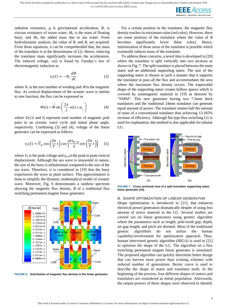
wave. Moreover, Fig. 6 demonstrates a rainbow spectrum
showing the magnetic flux density, B of a traditional flux
switching permanent magnet linear generator.
FIGURE 6. Distribution of magnetic flux density in the linear generator.
For a certain position in the translator, the magnetic flux
density reaches its maximum value (red color). However, there
are some portions of the translator where the value of B
becomes significantly lower (blue color). Hence,
minimization of those areas of the translator is possible which
eventually reduces mass of the translator.
To address these concerns, a novel idea is developed in [20]
where the translator is split vertically into two sections as
shown in Fig. 7. The split translator is placed between the main
stator and an additional supporting stator. The size of the
supporting stator is chosen in such a manner that it supports
the translator to pass all the flux and accommodates the area
where the maximum flux density occurs. The trapezoidal
shape of the supporting stator creates hollow spaces which is
covered by nonmagnetic material in [19] as denoted by
“NMM”. This new generator having two 7.5mm thick
translators and the traditional 24mm translator can generate
equal amount of power. The translator retains half the amount
of mass of a conventional translator thus achieving 13.185%
increase of efficiency. Although flat type flux switching LG is
used for explanation, this method is also applicable for tubular
LG.
(a) (b)
FIGURE 7. Cross sectional view of a split translator supporting stator linear generator [19].
B. SHAPE OPTIMIZATION OF LINEAR GENERATOR
Shape optimization is introduced in [21], that enhances
electrical power generation dramatically despite of using less
amount of active material in the LG. Several studies are
carried out on linear generators using genetic algorithm
where the parameters such as length, pole-tooth gap, depth,
air-gap length, and pitch are deemed. Most of the traditional
genetic algorithms do not utilize the human
capability/involvement for optimization approach. Thus,
human intervened genetic algorithm (HIGA) is used in [21]
to optimize the shape of the LG. The algorithm on a flux
switching permanent magnet linear generator is simulated.
The proposed algorithm can quickly determine better design
that can harvest more power than existing schemes with
reduced number of generations. Bezier curve is used to
describe the shape of stator and translator teeth. In the
beginning of the process, four different shapes of stators and
translators are considered as initial population. Afterwards,
the output powers of these shapes were observed to identify

This work is licensed under a Creative Commons Attribution 4.0 License. For more information, see https://creativecommons.org/licenses/by/4.0/.
This article has been accepted for publication in a future issue of this journal, but has not been fully edited. Content may change prior to final publication. Citation information: DOI10.1109/ACCESS.2020.3012662, IEEE Access
7
the best structure and the stator-translator combination. The
stators having curved edges have performed better than their
sharped edged counterparts. After 4 generations, two
translators with the highest fitness values were selected.
Then the performance of the proposed structure with and
without applying HIGA are compared to the same linear
generator. The shape of the proposed structure significantly
reduces the reluctance as well as leakage flux than the
structure without applying HIGA. Moreover, the flux density
(in both stator and translator) is also appreciably higher in
the proposed structure. Even though there is not much
change in eddy current between the two structures, the
reduction of hysteresis loss is appreciable. Furthermore, the
voltage and flux linkage between the two structures show
that the proposed structure outperforms. It experiences less
applied force under same loading conditions. The importance
of selecting proper Bezier curve is emphasized for
developing the linear generator. Another structure with an
improper and trivial selection of Bezier curve demonstrates
that a considerable amount of flux density is reduced
throughout the structure. By adopting HIGA, the power is
increased by 26.6% while the size of the machine is reduced
by 14.19%.
Moreover, the flux intensity, density, and lines for both
optimized and un-optimized stator tooth are shown where
more flux linkage for optimized stator teeth is observed. The
optimized values of inductance and capacitance of the filter for
which under-, over-, and critically damped voltage is observed
and overshoot is minimized. The electrical parameters and the
final optimized stator tooth are also shown in [18]. The
optimized curvature is approximated by a polynomial.
The force ripples are effectively minimized in the proposed
dual port linear generator while considering without
optimization, slope optimization, and slope-curvature
optimization. Furthermore, the core loss for both with and
without optimization of stator teeth are also shown where the
core loss is reduced in the optimized design. Additionally, the
hysteresis loss and eddy current losses are also decreased
accordingly. It is mentioned that the proposed dual port linear
generator with slope and curve optimization has reduced the
force ripples by approximately 40.98% and the generated
power is increased by approximately 17.98W.
It is found from this discussion that, optimization of the
shape has been introduced very recently to enhance the
performance of LG. Moreover, to obtain better power output
by improved dynamics, weight of the LG is also minimized.
V. SUPERCONDUCTING LINEAR GENERATOR
The electrical power extraction from the traditional generator
is inadequate because of armature resistance. Since there is no
internal resistance in superconductor, copper loss can be
minimized by replacing copper conductor with it. As such, the
overall power loss reduces and hence the power output
increases. Based on the critical temperature, which is
required to maintain superconductivity, superconductors are
classified into two categories. One is low temperature
superconductor which demonstrates zero internal resistance
at extremely low temperature. It requires expensive liquid
helium to maintain this temperature. The other is high
temperature superconductor (HTS) which can be operated at
relatively higher temperature and can easily be maintained
by low cost liquid nitrogen. Most of the HTS are copper
oxides and are often referred as cuprates. The first generation
of superconductor is used in industries due to its
multifilamentary tape-based structure. As for the second
generation of superconductor, it has coated tape-based
structure. Moreover, its main attributes are enhanced current
density, greater tensile strength, and improved consistency.
Furthermore, if superconductors are utilized then it will
reduce the slot size of the winding compared to copper
winding provided that ratings of other parameters are equal.
The reason for this is due to higher current rating and zero
internal resistance of superconductor. Reduction in slot size
will eventually decrease size of the linear generator. Also,
the output power will be enhanced for avoiding copper loss.
Hence, for the same amount of power, the generator size can
be significantly reduced which in turn reduces the cost and
improve its usefulness.
Two models of superconducting linear synchronous
generators are proposed in [22]. The secondary mover has
either tape coil or bulk magnet array both of which is made of
HTS. The HTS bulk magnet is the replacement of
conventional permanent magnets whereas the HTS coils are
the replacement of conventional copper coil. Yttrium barium
copper oxide, a high temperature superconductor, is used for
the bulk magnet and Ansoft/Maxwell is used for simulation.
For the translator velocity (of this generator) 3m/s and the
airgap 2mm, B is increased from 2T to 4T. It results in no
load RMS voltage 28.9V for 2T and 108.9V for 4T. For 8mm
and 2mm air gap length, the no-load RMS voltages are 71.4V
and 108.6V, respectively at B=3T. Similar approaches were
made to HTS coil type generator except that excitation
current is varied as well. For the change in excitation current
from100A to 200A, the no-load RMS voltage increases from
76.4V to 123.9V.
It is commonly found that decrease in air gap or increase
any one of flux density, velocity, and excitation current
enhances the voltage and power in the HTS linear generators.
Another superconducting LG is proposed in [23] where
permanent magnets are placed in the stator. Simulation results
are presented for voltage, current, power, and applied force. It
is considered that the applied force is approximately 150N and
the velocity for the translator is 1m/s. The output power is the
product of applied force and velocity. From simulation results,
it is seen that the output power is close to 150W. It is also
shown that, if the air gap is changed, the current and voltage
also changes. The current is maximum for 1mm of airgap as it
is the minimum air gap length. Furthermore, the output voltage
is roughly a square wave which requires less filter to rectify.

This work is licensed under a Creative Commons Attribution 4.0 License. For more information, see https://creativecommons.org/licenses/by/4.0/.
This article has been accepted for publication in a future issue of this journal, but has not been fully edited. Content may change prior to final publication. Citation information: DOI10.1109/ACCESS.2020.3012662, IEEE Access
8
Effect of load variation is also presented in [23] where the
current and power drops significantly and terminal voltage
increases when load is decreased beyond 3Ω. For this reason,
3Ω is selected as operating point. From force, power and
efficiency plots it is found that the power is maximum at 2Ω,
but the efficiency and force are too low. Efficiency of the
proposed generator is 96% for 10Ω load resistance provided
that the frictional and other mechanical losses are neglected.
The core loss of the generator is only 0.3% which creates
negligible amount of heat. Since the superconducting property
of superconductors are likely to deteriorate beyond cryogenic
liquid temperature, the proposed generator is highly suitable to
incorporate superconductors.
Second generation HTS tape-based superconductor is used
in [24] which has an average thickness of 0.1mm and width
of 4mm. Fig. 8 illustrates the magnetic property of the
proposed superconductor based LG.
FIGURE 8. The superconducting LG: (a) magnetic field intensity and (b) flux density [24].
Moreover, its critical current rating is 400A and critical
temperature is 77K. Furthermore, it has a tensile strength of
500MPa. Fig. 9 shows the voltage and power waveform of a
linear generator having superconducting and ordinary copper
wire.
FIGURE 9. Comparison of (a) voltage and (b) power output.
Generator made of superconductor provides better terminal
voltage and power output than that of using copper. To
maintain the characteristics of the superconductor, it is
essential to minimize the temperature which is produced in the
generator. One of the main sources of heat is core loss which
can be minimize by applying advanced magnetic core. The
combination of DI MAX HF-10 (called HF-10 herein after)
based core and yttrium barium copper oxide (YBCO) based
superconductor performs better than other combinations as
shown in [24]. The power and core loss of steel, DI MAX M-
27 (called M-27 herein after), and HF-10 magnetic cores under
high temperature superconductor based linear generator are
also tabulated. It is observed that, HF-10 core outperforms the
other two by having less core loss and more output power. The
usual iron core demonstrates 6% core loss when it generates
302.1W power. Whereas M-27, a non-oriented iron core,
exhibits 331.3W output power with 2.65% core loss. For HF-
10, core loss is minimized to 2.4% with approximately 23W
additional output power compared to that of conventional one.
A superconductor-based generator is proposed in [25]
where the stator is made of neodymium iron boron (NdFeB)
permanent magnet and the translator has laminated
ferromagnetic core. The generator results more terminal
voltage and produces additional 30% electrical power than that
of the traditional one. YBCO is used for the winding of this
generator. Finite element technique through ANSYS/Maxwell
simulation software is used to demonstrate its performance.
The performances of the proposed and traditional generator
are compared where the proposed one demonstrates excellent
performance. Table I identifies the consequence in the LG for
using ordinary copper conductor and superconductor-based
winding.
TABLE I OUTCOME OF THE LG USING COPPER CONDUCTOR AND
SUPERCONDUCTOR BASED WINDING
Winding TYPE OF GENERATOR Outcome
Copper PMLG (stator or
translator)
High power loss due to internal
resistance
Low winding factor YBCO HTS Flux switching
PMLG
Higher output power
Terminal voltage increased [25]
YBCO HTS Linear synchronous generator
Voltage and power increased [22]
2G tape-based
superconductor
HTS LG Higher terminal voltage than
copper Output power increases [24]
This section shows the important features of HTS based
winding to be used in the superconducting LGs. HTS tapes
are suitable for constructing coils or armature winding in the
PMLG. It is also suitable for designing a superconducting
magnetic LG. With the HTS based PMLG, it is expected that,
much higher output power can be achieved in near future.
VI. SPECIAL PERMANENT MAGNETS IN LG
Most of the existing permanent magnet linear generator
incorporates conventional NdFeB permanent magnets. These

This work is licensed under a Creative Commons Attribution 4.0 License. For more information, see https://creativecommons.org/licenses/by/4.0/.
This article has been accepted for publication in a future issue of this journal, but has not been fully edited. Content may change prior to final publication. Citation information: DOI10.1109/ACCESS.2020.3012662, IEEE Access
9
permanent magnets tend to demagnetize when the temperature
of the generator increases. Thus, the power generation
decreases eventually. The following sub-sections describes the
way of preventing demagnetization, thus producing high
power.
A. APPLICATION OF HIGH-GRADE PM
High graded permanent magnets can retain its remanence
magnetism even at high amount of reverse magnetic field. A
PMLG with high graded N48H NdFeB is proposed in [26] to
maintain adequate amount of remanence in it. Temperature
effect on demagnetization is illustrated in Fig. 10. Fig. 10(a)
shows the comparison of demagnetization curve between
conventional N35 and proposed N48H under 60°C
temperature. N48H outperforms N35 in terms of magnetic
flux density and coercive field strength under the same
temperature. The proposed generator is simulated using
ANSYS/Maxwell. Finite element analysis is used to
demonstrate the results. The voltage, current, and power
comparison show that the N48H performs better in all these
aspects. Additionally, the core loss for using N48H is lower
than that of using N35 for the same power and the generator
with N48H delivers 44W more power than that for using
N35. Around 28% increase in electrical power is achieved by
integrating N48H instead of using conventional N35 for the
same design and other parameters.
Another high graded N28EH material for permanent
magnet is used in [27] and the results are compared with
conventional N35M PM. Fig. 10(b) depicts the magnetizing
curve for both of the materials. It is observed that the
performance of N28EH is better than using N35M at both
60°C and 100°C. Fig. 11 shows that at low temperature, usual
N35M graded permanent magnet can generate enough power
but it degrades at high temperature. This is due to reduced
residual magnetism.
FIGURE 10. Characteristics curves of (a) N48H and N35 at 60°; (b) N35M and N28EH at 60° and 100°.
FIGURE 11. Instantaneous power at 60° and 100°.
But, for selecting N28EH, the LG can generate more power
than that of using the other. Demagnetizing curves of N52,
N38, and NdFeB is plotted in Fig. 12. Outcome of N52 is
better than the other two materials. Therefore, using N52 with
Supermendur generates the highest electrical output power
than any combination formed by other materials.
FIGURE 12. Demagnetizing curves of conventional, NdFeB, N38, and N52.
B. APPLICATION OF HALBACH ARRAY
Halbach array is the special arrangement of permanent
magnets that results increase in magnetic field in a particular
direction. Quasi-Halbach magnetization structure is presented
in [28] where a tubular permanent magnet linear generator
with a bulged stator and auxiliary slots is used to reduce the
detent force. The detent force of a conventional 8 pole 12 slots
PMLG is compared with the proposed 9 pole 10 slots PMLG.
It is demonstrated that the proposed generator has reduced the
detent force by 82.56%. Furthermore, with the help of finite
element analysis and Fourier transformation, it is
demonstrated that changing the length of the bulged stator
significantly reduces detent force. Through parametrization
analysis, size of the bulged stator is optimized. For the size of
3mm, the detent force reduces from 159.72N to 20.47N which
is a reduction of around 87.18%. Additionally, the relation of
voltage and airgap is analyzed where it is demonstrated that
1mm of airgap can results more voltage than that of using
3mm of airgap. However, for manufacturing ease, it is
suggested to use 3mm of airgap.
An external tubular PMLG is demonstrated in [29] where
quasi-Halbach array is used to maximize the airgap flux
density. Moreover, auxiliary frictional slots and assistant teeth
are incorporated to reduce detent force. The cogging forces are
compared with and without auxiliary slots. When the width of
the auxiliary slots is adjusted to 8mm, detent force is reduced
by approximately 68.98%. At 18Ω loading condition, the
power density increases by 7–8 times with an efficiency of
90.03%. Moreover, a prototype is built to compare the
simulation results with the experimental one.
C. PREVENTION OF DEMAGNETIZATION
Demagnetization or degradation of the remanence magnetism
often occurs in the LG while producing electrical power. It can
be minimized by either using high graded permanent magnets,
maintaining low temperature, or avoiding permanent magnets.
High graded permanent magnet which is used in the LG for

This work is licensed under a Creative Commons Attribution 4.0 License. For more information, see https://creativecommons.org/licenses/by/4.0/.
This article has been accepted for publication in a future issue of this journal, but has not been fully edited. Content may change prior to final publication. Citation information: DOI10.1109/ACCESS.2020.3012662, IEEE Access
10
preventing demagnetization is costly. Hence, to prevent
demagnetization, temperature control could be one of the
effective methods for the PMLG.
1) ELECTROMAGNETIC AND SUPERCONDUCTING LG
A novel electromagnetic linear generator is proposed in [30]
which is almost solve the demagnetizing problem. The LG
uses a permanent magnet excitation generator to excite other
electromagnetic LGs. Moreover, m-shaped poles and pole
shifting technique are used to reduce the amount of leakage
flux, force ripples, and cogging forces. ANSYS/Ansoft is used
for performance evaluation. However, the excitation generator
consumes 25% of the total generated power.
2) TEMPERATURE MINIMIZATION IN THE PMLG
A cooling system which can reduce the rising temperature of
the generator is proposed in [31]. The cooling system contains
a control unit, a chiller, a dehumidifier-based air handling unit,
water pipes to circulate the chilled water. Fig. 13 shows the
block diagram of the chiller embedded in PMLG. The model
demonstrates better performance regarding terminal voltage,
current, and generated power. It is demonstrated that the
proposed cooling system based PMLG provides 2.2kW more
power than its traditional counterpart. Moreover, the
dehumidifier controls the humidity in the linear generator
which would increase its lifespan.
FIGURE 13. Water cooling system for linear generator [31].
Other than these permanent magnets, the compound Fe16N2
known as iron nitride is applied in [32] which exhibits the best
performance among all conventional rare earth free permanent
magnets. Table II presents outcomes of the LG for application
of various high graded permanent magnets along with
conventional one.
In some cases, the permanent magnet is used in the stator or
translator as mentioned in the parenthesis (in Table II). A
comparison is also presented for the electrical parameters
considering the existing rare earth free permanent magnet with
the highest magnetic energy product and the proposed one.
It can be summarized from this section that, the research in
developing permanent magnets results tremendous
improvement in designing LGs. For viable operation at higher
temperature, traditional permanent magnets are replaced with
high graded ones. Moreover, reduction of detent force is
obtained with the use of Halbach array. Demagnetization of
permanent magnets due to higher temperature is mitigated
with the help of water-cooling system. It can further be
reduced by using superconductors.
TABLE II OUTCOME OF THE LG FOR USING HIGH GRADED PERMANENT MAGNETS
Permanent magnet
Type of generator Outcome
Conventional
NdFeB N30,
N35
PMLG (stator or
translator) Low remanence magnetism
Low coercive force
Low magnetic energy product
N48H
(NdFeB)
PMLG (stator) Output power increased
Costly [26]
N28EH PMLG (stator) Increased output power than N35M
[27]
Quasi-Halbach array
External tubular PMLG (stator)
Reduced detent force
High efficiency
Appreciably high output power [29]
N52 PMLG (translator)
Remarkably high remanence
magnetism
Low coercive force
High energy product [33]
VII. MAGNETIC CORES IN LINEAR GENERATOR
Copper losses and core losses are dissipated as thermal
energy which eventually diminishes the remanence
magnetism within the permanent magnets. Traditionally, iron
cores are used in the permanent magnet linear generator which
are often detrimental for high amount of core losses during
extraction of wave energy. Moreover, these cores tend to
saturate at lower B resulting in low output power. Thus, there
is great need of materials which are suitable to be used as
magnetic core. Numerous analyses are found where the use
of graded cores results noticeable reduction in core loss.
A. APPLICATION OF HIGH-GRADE STEEL CORE
High grade steel core can significantly increase the power
generating and reduce the core loss. Thus, it can play vital role
of reducing temperature rise in the linear generator because of
core loss. High graded steel cores are often classified into non
grain oriented and grain oriented. Performances of Armco DI-
MAX non-oriented electrical steel M-27 and HF-10 based
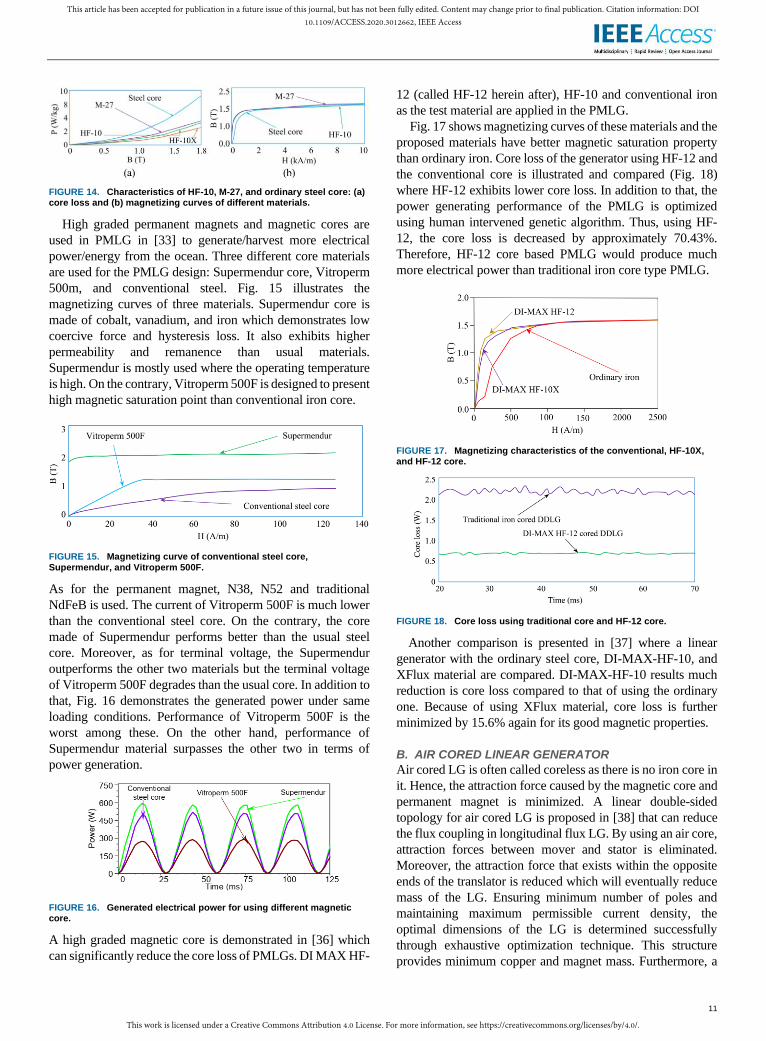
cores are presented in [34]. Fig. 14 shows the core loss profile
and magnetization curves of HF-10, HF-10X, usual steel core,
and M-27 cores under 50Hz frequency. M-27 provides better
saturation than HF-10 as plotted in Fig. 14(b), but its core loss
is noticeably higher than HF-10. Performance of DI MAX HF-
10X (called HF-10X herein after) based core is compared with
the conventional iron core in [35]. HF-10X shows the lowest
core loss and better performance among the others.
This work is licensed under a Creative Commons Attribution 4.0 License. For more information, see https://creativecommons.org/licenses/by/4.0/.
This article has been accepted for publication in a future issue of this journal, but has not been fully edited. Content may change prior to final publication. Citation information: DOI10.1109/ACCESS.2020.3012662, IEEE Access
11
FIGURE 14. Characteristics of HF-10, M-27, and ordinary steel core: (a) core loss and (b) magnetizing curves of different materials.
High graded permanent magnets and magnetic cores are
used in PMLG in [33] to generate/harvest more electrical
power/energy from the ocean. Three different core materials
are used for the PMLG design: Supermendur core, Vitroperm
500m, and conventional steel. Fig. 15 illustrates the
magnetizing curves of three materials. Supermendur core is
made of cobalt, vanadium, and iron which demonstrates low
coercive force and hysteresis loss. It also exhibits higher
permeability and remanence than usual materials.
Supermendur is mostly used where the operating temperature
is high. On the contrary, Vitroperm 500F is designed to present
high magnetic saturation point than conventional iron core.
FIGURE 15. Magnetizing curve of conventional steel core, Supermendur, and Vitroperm 500F.
As for the permanent magnet, N38, N52 and traditional
NdFeB is used. The current of Vitroperm 500F is much lower
than the conventional steel core. On the contrary, the core
made of Supermendur performs better than the usual steel
core. Moreover, as for terminal voltage, the Supermendur
outperforms the other two materials but the terminal voltage
of Vitroperm 500F degrades than the usual core. In addition to
that, Fig. 16 demonstrates the generated power under same
loading conditions. Performance of Vitroperm 500F is the
worst among these. On the other hand, performance of
Supermendur material surpasses the other two in terms of
power generation.
FIGURE 16. Generated electrical power for using different magnetic core.
A high graded magnetic core is demonstrated in [36] which
can significantly reduce the core loss of PMLGs. DI MAX HF-
12 (called HF-12 herein after), HF-10 and conventional iron
as the test material are applied in the PMLG.
Fig. 17 shows magnetizing curves of these materials and the
proposed materials have better magnetic saturation property
than ordinary iron. Core loss of the generator using HF-12 and
the conventional core is illustrated and compared (Fig. 18)
where HF-12 exhibits lower core loss. In addition to that, the
power generating performance of the PMLG is optimized
using human intervened genetic algorithm. Thus, using HF-
12, the core loss is decreased by approximately 70.43%.
Therefore, HF-12 core based PMLG would produce much
more electrical power than traditional iron core type PMLG.
FIGURE 17. Magnetizing characteristics of the conventional, HF-10X, and HF-12 core.
FIGURE 18. Core loss using traditional core and HF-12 core.
Another comparison is presented in [37] where a linear
generator with the ordinary steel core, DI-MAX-HF-10, and
XFlux material are compared. DI-MAX-HF-10 results much
reduction is core loss compared to that of using the ordinary
one. Because of using XFlux material, core loss is further
minimized by 15.6% again for its good magnetic properties.
B. AIR CORED LINEAR GENERATOR
Air cored LG is often called coreless as there is no iron core in
it. Hence, the attraction force caused by the magnetic core and
permanent magnet is minimized. A linear double-sided
topology for air cored LG is proposed in [38] that can reduce
the flux coupling in longitudinal flux LG. By using an air core,
attraction forces between mover and stator is eliminated.
Moreover, the attraction force that exists within the opposite
ends of the translator is reduced which will eventually reduce
mass of the LG. Ensuring minimum number of poles and
maintaining maximum permissible current density, the
optimal dimensions of the LG is determined successfully
through exhaustive optimization technique. This structure
provides minimum copper and magnet mass. Furthermore, a
This work is licensed under a Creative Commons Attribution 4.0 License. For more information, see https://creativecommons.org/licenses/by/4.0/.
This article has been accepted for publication in a future issue of this journal, but has not been fully edited. Content may change prior to final publication. Citation information: DOI10.1109/ACCESS.2020.3012662, IEEE Access
12
1kW rated protype for validation is developed. The
experimental results reveal that around 95% efficiency with
approximately unity power factor can be achieved using the
proposed structure.
An air-cored tube structured permanent magnet linear
generator is proposed in [39] in which cogging force, ratio of
radial Lorentz force, and axial Lorentz force are reduced.
Furthermore, the proposed generator can deliver higher power
than the conventional one. Additionally, a pair of anti-parallel
thyristors are used to bypass the inactive coils. Moreover,
seven times reduction in thermal loss is achieved unlike any
conventional bypass scheme. Also, the thermal loss in the
proposed model is not contingent on number of coils.
Another air core LG is presented in [40] where a prototype
is built and tested in two different cases. Each section of the
stator consists of three windings placed side by side. Total 38
sections are connected in series and are placed in an aluminum
ring. Furthermore, two cases are considered for testing
purpose. In the first case, there is no overlap between stator
and the translator at the stroke end. For the second case, full
overlap occurs between the stator and the translator. Two cases
are implemented with the help of a crank shaft and a drive
motor. The drive motor is used to simulate oceanic waves.
Three phase ac supply is initially rectified and further
converted to ac waveform to control the frequency. As the
frequency varies, the motor speed also changes accordingly.
Since, direct connection of a single LG to the grid is not
feasible, output of the LG is feed to a dc bus where the dc
voltage is regulated. Lastly, it is demonstrated that the zero
overlapping case results 46% increase of power to weight
ratio.
An approach is adopted in [41] that makes an air cored
electric machine retain a concentric arrangement of solenoid-
shaped coils, stator, and rotor. This would support
manufacture and maintenance. 3D finite element analysis is
performed to examine the performance of the machine.
Relation between the airgap length and pole numbers through
geometrical analysis are determined. The most optimum
number of poles for the proposed design is 32. Magnetic and
geometric properties are studied using magnetic circuit
analysis. Considering thermal environment, the number of
turns per phase and rated parameters are examined using
electrical circuit analysis. Finally, the machine demonstrates
at least 90% efficiency at different operational environment.
The proposed machine offers simplicity in terms of
construction. The main demerit of this generator is that its
power density is much lower than other iron cored
conventional machines.
At the end of this section it can be concluded that, reducing
core loss is the way to increase efficiency. In case of any LG
this is achieved by using high graded steel cores. Moreover,
air cored LG can almost reduce core loss that demonstrates an
advantage over the iron cored LG. But it is at the rudimentary
stage and its size is found quite large compared to its generated
power.
VIII. PIEZOELECTRIC GENERATOR
Energy converters or harvesters made of prominent
polyvinylidene fluoride materials are used to harness
substantial amount of electrical power form the ocean. Energy
converters can be used to supply electrical power to
applications that are operated in ocean such as different
electrical sensing elements, floating harbors, robots etc. The
efficiency related to energy conversion of wave energy
converters (WECs) can be enhanced by integrating various
types of piezoelectric materials. Experiments show that using
this methodology, 0.2μW electric power with 2.2V can be
acquired by stressing the material with a pressure of 1.196kPa
at 20Hz frequency. A piezoelectric WEC is designed, semi-
submerged in ocean, and anchored in the seabed [42]. The
semi-submerged structure of energy harvester produces
vibration corresponding to the oceanic wave’s dynamic
oscillation. The external force caused by oceanic wave can
continuously deform the piezoelectric plates because it is
placed on the member of the harvester. Depending on the
material of piezoelectric transducer, different level of voltages
can be generated by transducing the stresses on the device.
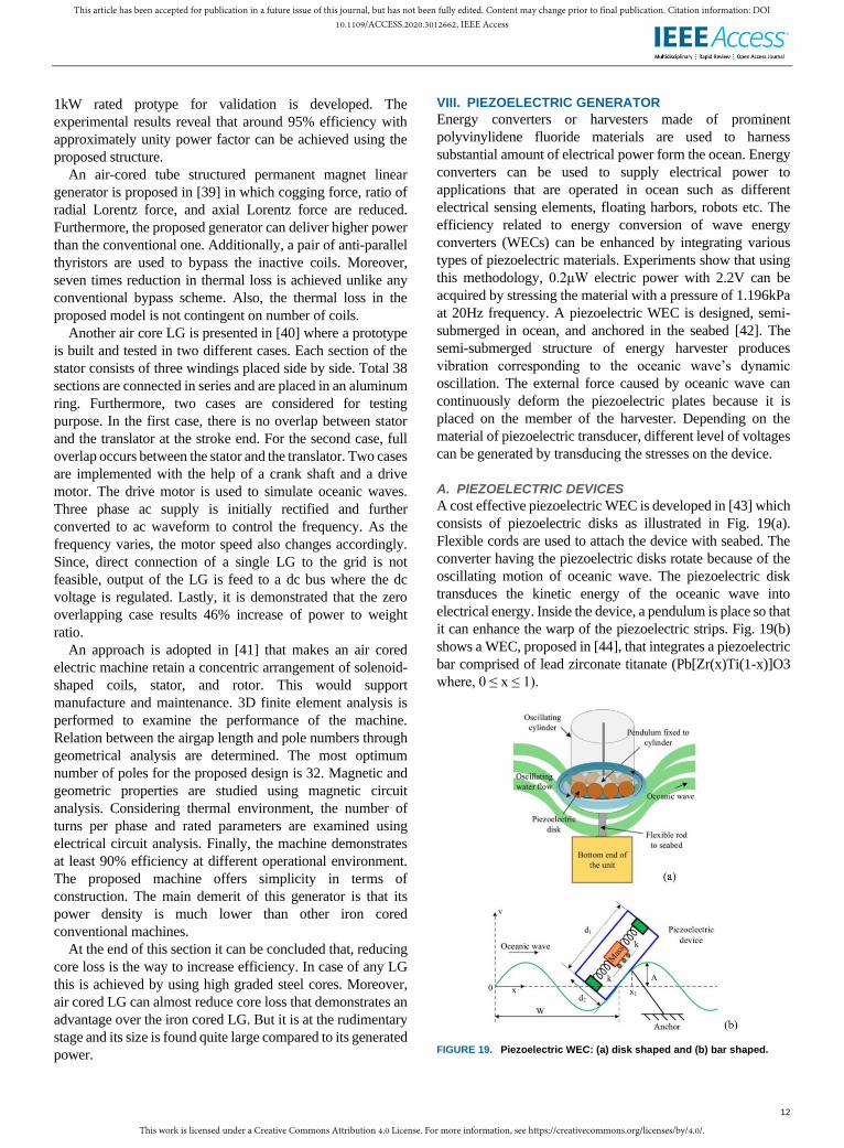
A. PIEZOELECTRIC DEVICES
A cost effective piezoelectric WEC is developed in [43] which
consists of piezoelectric disks as illustrated in Fig. 19(a).
Flexible cords are used to attach the device with seabed. The
converter having the piezoelectric disks rotate because of the
oscillating motion of oceanic wave. The piezoelectric disk
transduces the kinetic energy of the oceanic wave into
electrical energy. Inside the device, a pendulum is place so that
it can enhance the warp of the piezoelectric strips. Fig. 19(b)
shows a WEC, proposed in [44], that integrates a piezoelectric
bar comprised of lead zirconate titanate (Pb[Zr(x)Ti(1-x)]O3
where, 0 ≤ x ≤ 1).
FIGURE 19. Piezoelectric WEC: (a) disk shaped and (b) bar shaped.

This work is licensed under a Creative Commons Attribution 4.0 License. For more information, see https://creativecommons.org/licenses/by/4.0/.
This article has been accepted for publication in a future issue of this journal, but has not been fully edited. Content may change prior to final publication. Citation information: DOI10.1109/ACCESS.2020.3012662, IEEE Access
13
The external force caused by oceanic wave is amplified by
a vertical lever which is attached to the piezoelectric bar. A
mass-spring arrangement is adopted to create vibration from
wave oscillations. Two piezoelectric members are connected
to the mass by springs. The purpose of using the spring is to
avoid direct collision between the mass and the disk. Also, it
gradually increases or decreases the stress on the disk.
When the device experiences an oscillating wave, vibration
is created due to the movement of the mass inside the device.
As a result, the member experiences continuous deformation
caused by vibration. Thus, vibration is transduced into
electrical power through piezoelectric materials. Piezoelectric
materials can generate electrical power if the heave and pitch
motion of oceanic waves are utilized. It employs a floating
buoy which is tied to the seabed by connecting rope as
illustrated in Fig. 20 [45]. The piezoelectric device on the left
is mounted to the connecting shaft of the buoy. Therefore, any
heaving motion of the buoy creates rolling motion in the
device. As it experiences rolling motion, the pendulum tends
to deform the piezoelectric disks which results in generation
of electrical power. Many small sized devices are connected to
the shaft which would appear as a branch of a tree having
leaves on it. Therefore, small portion of electrical energy
coming from each of the devices accumulates into a large
amount of energy. The buoy situated at the right-hand side
(Fig. 20) encapsulates the piezoelectric device. If the buoy
encounters pitching motion, then the pendulum also moves
accordingly and creates stress on the disks. Hence, electrical
energy is obtained from both heaving and pitching motion.
Another type of piezoelectric harvester is proposed in [45]
using four disks made of lead zirconate titanate along with a
balanced type pendulum. These devices are also known as
flexible piezoelectric device (FPED). Each of these elements
are confined in a carrier box made of brass material. In Fig. 20,
the device is located inside the box and labeled as “Energy
harvesting unit”. Water can easily enter the box or can easily
go out from the device which disturbs the balanced position of
the pendulum.
FIGURE 20. WEC using (a) heave and (b) pitch motion of sea waves.
Thus, the pendulum creates stress on FPED and hence it
gets deformed with electrical power generation. A
piezoelectric material based oceanic energy harvester is
designed in [46] which is illustrated in Fig. 21. The harvester
is placed just beside a vertical oceanic cliff. It comprises of
vertically placed piezoelectric thin plates which get stressed
when oceanic waves pass through them. Consequently, wave
motion is transduced into electrical energy and passed to
external circuitry.
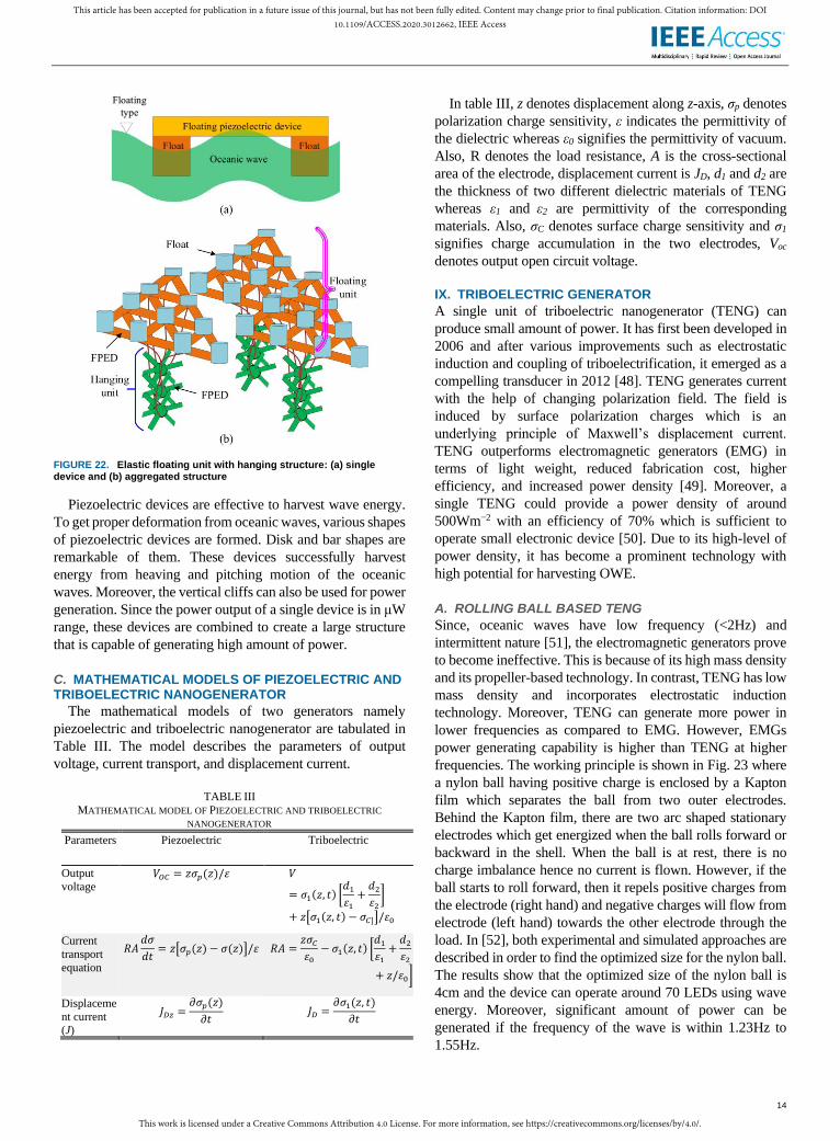
An experimental test on elastic floating unit with hanging
structure is conducted in water tanks in [47]. Both floating type
and submerged type buoys are used in the test which are
depicted in Fig. 22(a). The height and width of the test float is
115mm and 85mm, respectively. An artificial wave is created
in a wave tank having an amplitude of 0.077m and 1m
wavelength. The FPED is mounted on the top of the float for
submerged type devices. In case of floating type device, it is
placed at the bottom of the floats. For both submerged and
floating type devices, connecting ropes/rods are used to attach
the devices with the tank. Since, FPEDs are made of
polyvinylidene fluoride material, efficacious electrical
performance can be obtained by choosing the length of the
polyvinylidene fluoride layer from 0.1mm to 0.5mm, but it is
recommended not to exceed 0.5mm.
FIGURE 21. (a) experimental tests of elastic floating unit with hanging structure placed beside a vertical oceanic cliff.
B. AGGREGATED FORM
A single piezoelectric device produces extremely small
amount of power. To increase power, these devices are needed
to be accumulated. Thus, an aggregated form of elastic floating
unit with hanging structure (EFHAS) is proposed in [47]
which can harvest oceanic energy. It consists of a hanging and
a floating section as illustrated in Fig. 22(b).
The floating branches are connected to each other by
flexible piezoelectric device. There are few vertical and
horizontal branches of flexible piezoelectric device in the
hanging section that can generate electrical power from the
heaving motion of oceanic wave. This device can generate
power even from weak oceanic waves which is highly
beneficial. Wind ocean farm can be established where a series
of EFHAS surrounds the offshore wind turbines. Therefore,
wind turbines extract wind energy and the EFHASs harness
oceanic wave energy from the ocean. This combination is
advantageous since the EFHAS can absorb the vigorous power
of oceanic waves thus protecting the wind turbines.
This work is licensed under a Creative Commons Attribution 4.0 License. For more information, see https://creativecommons.org/licenses/by/4.0/.
This article has been accepted for publication in a future issue of this journal, but has not been fully edited. Content may change prior to final publication. Citation information: DOI10.1109/ACCESS.2020.3012662, IEEE Access
14
FIGURE 22. Elastic floating unit with hanging structure: (a) single device and (b) aggregated structure
Piezoelectric devices are effective to harvest wave energy.
To get proper deformation from oceanic waves, various shapes
of piezoelectric devices are formed. Disk and bar shapes are
remarkable of them. These devices successfully harvest
energy from heaving and pitching motion of the oceanic
waves. Moreover, the vertical cliffs can also be used for power
generation. Since the power output of a single device is in μW
range, these devices are combined to create a large structure
that is capable of generating high amount of power.
C. MATHEMATICAL MODELS OF PIEZOELECTRIC AND TRIBOELECTRIC NANOGENERATOR
The mathematical models of two generators namely
piezoelectric and triboelectric nanogenerator are tabulated in
Table III. The model describes the parameters of output
voltage, current transport, and displacement current.
TABLE III
MATHEMATICAL MODEL OF PIEZOELECTRIC AND TRIBOELECTRIC
NANOGENERATOR
Parameters Piezoelectric Triboelectric
Output
voltage 𝑉𝑂𝐶 = 𝑧𝜎𝑝(𝑧)/𝜀 𝑉
= 𝜎1(𝑧, 𝑡) [𝑑1
𝜀1
+𝑑2
𝜀2
]
+ 𝑧[𝜎1(𝑧, 𝑡) − 𝜎𝐶]]/𝜀0
Current
transport
equation
𝑅𝐴𝑑𝜎
𝑑𝑡= 𝑧[𝜎𝑝(𝑧) − 𝜎(𝑧)]/𝜀 𝑅𝐴 =
𝑧𝜎𝐶
𝜀0
− 𝜎1(𝑧, 𝑡) [𝑑1
𝜀1
+𝑑2
𝜀2
+ 𝑧/𝜀0]
Displaceme
nt current (J)
𝐽𝐷𝑧 =𝜕𝜎𝑝(𝑧)
𝜕𝑡 𝐽𝐷 =
𝜕𝜎1(𝑧, 𝑡)
𝜕𝑡
In table III, z denotes displacement along z-axis, σp denotes
polarization charge sensitivity, ε indicates the permittivity of
the dielectric whereas ε0 signifies the permittivity of vacuum.
Also, R denotes the load resistance, A is the cross-sectional
area of the electrode, displacement current is JD, d1 and d2 are
the thickness of two different dielectric materials of TENG
whereas ε1 and ε2 are permittivity of the corresponding
materials. Also, σC denotes surface charge sensitivity and σ1
signifies charge accumulation in the two electrodes, Voc
denotes output open circuit voltage.
IX. TRIBOELECTRIC GENERATOR
A single unit of triboelectric nanogenerator (TENG) can
produce small amount of power. It has first been developed in
2006 and after various improvements such as electrostatic
induction and coupling of triboelectrification, it emerged as a
compelling transducer in 2012 [48]. TENG generates current
with the help of changing polarization field. The field is
induced by surface polarization charges which is an
underlying principle of Maxwell’s displacement current.
TENG outperforms electromagnetic generators (EMG) in
terms of light weight, reduced fabrication cost, higher
efficiency, and increased power density [49]. Moreover, a
single TENG could provide a power density of around
500Wm−2 with an efficiency of 70% which is sufficient to
operate small electronic device [50]. Due to its high-level of
power density, it has become a prominent technology with
high potential for harvesting OWE.
A. ROLLING BALL BASED TENG
Since, oceanic waves have low frequency (<2Hz) and
intermittent nature [51], the electromagnetic generators prove
to become ineffective. This is because of its high mass density
and its propeller-based technology. In contrast, TENG has low
mass density and incorporates electrostatic induction
technology. Moreover, TENG can generate more power in
lower frequencies as compared to EMG. However, EMGs
power generating capability is higher than TENG at higher
frequencies. The working principle is shown in Fig. 23 where
a nylon ball having positive charge is enclosed by a Kapton
film which separates the ball from two outer electrodes.
Behind the Kapton film, there are two arc shaped stationary
electrodes which get energized when the ball rolls forward or
backward in the shell. When the ball is at rest, there is no
charge imbalance hence no current is flown. However, if the
ball starts to roll forward, then it repels positive charges from
the electrode (right hand) and negative charges will flow from
electrode (left hand) towards the other electrode through the
load. In [52], both experimental and simulated approaches are
described in order to find the optimized size for the nylon ball.
The results show that the optimized size of the nylon ball is
4cm and the device can operate around 70 LEDs using wave
energy. Moreover, significant amount of power can be
generated if the frequency of the wave is within 1.23Hz to
1.55Hz.
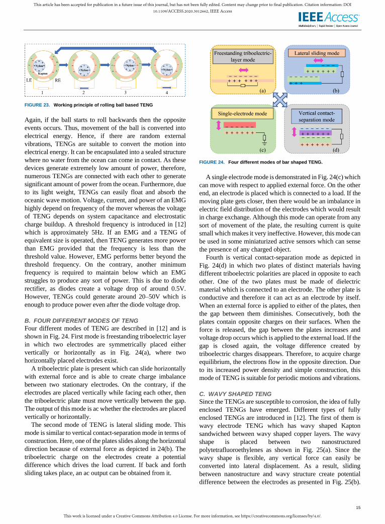
This work is licensed under a Creative Commons Attribution 4.0 License. For more information, see https://creativecommons.org/licenses/by/4.0/.
This article has been accepted for publication in a future issue of this journal, but has not been fully edited. Content may change prior to final publication. Citation information: DOI10.1109/ACCESS.2020.3012662, IEEE Access
15
FIGURE 23. Working principle of rolling ball based TENG
Again, if the ball starts to roll backwards then the opposite
events occurs. Thus, movement of the ball is converted into
electrical energy. Hence, if there are random external
vibrations, TENGs are suitable to convert the motion into
electrical energy. It can be encapsulated into a sealed structure
where no water from the ocean can come in contact. As these
devices generate extremely low amount of power, therefore,
numerous TENGs are connected with each other to generate
significant amount of power from the ocean. Furthermore, due
to its light weight, TENGs can easily float and absorb the
oceanic wave motion. Voltage, current, and power of an EMG
highly depend on frequency of the mover whereas the voltage
of TENG depends on system capacitance and electrostatic
charge buildup. A threshold frequency is introduced in [12]
which is approximately 5Hz. If an EMG and a TENG of
equivalent size is operated, then TENG generates more power
than EMG provided that the frequency is less than the
threshold value. However, EMG performs better beyond the
threshold frequency. On the contrary, another minimum
frequency is required to maintain below which an EMG
struggles to produce any sort of power. This is due to diode
rectifier, as diodes create a voltage drop of around 0.5V.
However, TENGs could generate around 20–50V which is
enough to produce power even after the diode voltage drop.
B. FOUR DIFFERENT MODES OF TENG
Four different modes of TENG are described in [12] and is
shown in Fig. 24. First mode is freestanding triboelectric layer
in which two electrodes are symmetrically placed either
vertically or horizontally as in Fig. 24(a), where two
horizontally placed electrodes exist.
A triboelectric plate is present which can slide horizontally
with external force and is able to create charge imbalance
between two stationary electrodes. On the contrary, if the
electrodes are placed vertically while facing each other, then
the triboelectric plate must move vertically between the gap.
The output of this mode is ac whether the electrodes are placed
vertically or horizontally.
The second mode of TENG is lateral sliding mode. This
mode is similar to vertical contact-separation mode in terms of
construction. Here, one of the plates slides along the horizontal
direction because of external force as depicted in 24(b). The
triboelectric charge on the electrodes create a potential
difference which drives the load current. If back and forth
sliding takes place, an ac output can be obtained from it.
FIGURE 24. Four different modes of bar shaped TENG.
A single electrode mode is demonstrated in Fig. 24(c) which
can move with respect to applied external force. On the other
end, an electrode is placed which is connected to a load. If the
moving plate gets closer, then there would be an imbalance in
electric field distribution of the electrodes which would result
in charge exchange. Although this mode can operate from any
sort of movement of the plate, the resulting current is quite
small which makes it very ineffective. However, this mode can
be used in some miniaturized active sensors which can sense
the presence of any charged object.
Fourth is vertical contact-separation mode as depicted in
Fig. 24(d) in which two plates of distinct materials having
different triboelectric polarities are placed in opposite to each
other. One of the two plates must be made of dielectric
material which is connected to an electrode. The other plate is
conductive and therefore it can act as an electrode by itself.
When an external force is applied to either of the plates, then
the gap between them diminishes. Consecutively, both the
plates contain opposite charges on their surfaces. When the
force is released, the gap between the plates increases and
voltage drop occurs which is applied to the external load. If the
gap is closed again, the voltage difference created by
triboelectric charges disappears. Therefore, to acquire charge
equilibrium, the electrons flow in the opposite direction. Due
to its increased power density and simple construction, this
mode of TENG is suitable for periodic motions and vibrations.
C. WAVY SHAPED TENG
Since the TENGs are susceptible to corrosion, the idea of fully
enclosed TENGs have emerged. Different types of fully
enclosed TENGs are introduced in [12]. The first of them is
wavy electrode TENG which has wavy shaped Kapton
sandwiched between wavy shaped copper layers. The wavy
shape is placed between two nanostructured
polytetrafluoroethylenes as shown in Fig. 25(a). Since the
wavy shape is flexible, any vertical force can easily be
converted into lateral displacement. As a result, sliding
between nanostructure and wavy structure create potential
difference between the electrodes as presented in Fig. 25(b).

This work is licensed under a Creative Commons Attribution 4.0 License. For more information, see https://creativecommons.org/licenses/by/4.0/.
This article has been accepted for publication in a future issue of this journal, but has not been fully edited. Content may change prior to final publication. Citation information: DOI10.1109/ACCESS.2020.3012662, IEEE Access
16
When force is removed and the wavy shape returns to its
original shape, sliding between two structures occurs again,
but in reverse direction. Compression and expansion of the
wavy structure creates ac current. Thus, this device can
convert the water impact energy of oceanic wave into
electrical energy. Experiments show that a wave of 0.2m
amplitude having a speed of 1.2m/s can provide 30V and 6μA
using wavy TENG. Hence, this is a promising device for
oceanic wave energy conversion.
FIGURE 25. Wavy shape TENG: (a) placed between two polytetrafluoroethylene and (b) its illustration [12].
D. DUCK SHAPED TENG
Duck shaped TENG and its multilayer form are illustrated in
[53] where nylon balls are placed on Kapton films and
electrodes are placed beneath the films. The structure of the
TENG mimics the salter’s duck which can convert wave
energy into electrical energy. From Fig. 26, positively charged
nylon balls roll back and forth and ac current passes through
the electrodes accordingly. The sequence of operation is
clockwise.
FIGURE 26. Working principle of duck shaped TENG.
The triboelectric nanogenerators which are discussed can
generate very low amount of power for a single unit. However,
if numerous TENGs are integrated to create a network, then its
network can generate substantial amount of power. Moreover,
network of TENGs can be used to harvest oceanic wave
energy from undercurrents as well as surface waves unlike its
EMG counterpart. Furthermore, most of the oceanic waves are
multidirectional which makes network of TENGs suitable for
harvesting OWE. Network of TENGs can easily be arranged
in both epicontinental sea and in offshore locations. A hybrid
TENG is developed in [54] which is a combination of
rotational disk based TENG and a liquid solid contact TENG.
The disk based TENG shown in Fig. 27 can utilize the
irregular rotational motion and its power density is
approximately 42.6Wm−2 at 1000rpm speed. The liquid solid
contact TENG operates using the vertical contact separation
mode. Water and polydimethylsiloxane create potential
difference between the copper electrodes because of
continuous contact and separation. Its power density is
50mWm−2 at 5Hz. The hybrid TENGs are expected to be able
to extract current motion from the ocean.
FIGURE 27. Operation of the disk based TENG.
A swing structured TENG is simulated and tested in [55]
for wave energy extraction. The device exhibited 0.48mW of
average power. Using wave energy, the device successfully
powered transportable electronic devices through which
temperature and other environmental assessments are carried
out. A spherical ball based multilayer TENG in [56] is used to
extract energy from multidirectional water wave. Assisted
structure with six springs along with power management
module enables it to demonstrate maximum output of 8.5mW
with 250V, and 80μA. Another spherical ball based TENG
network shown in Fig. 28(a) is proposed in [57] where
millions of spherical TENGs are integrated to form a structure
which looks like fishing net. Coupling the TENGs can
enhance the charge output by 10 times as demonstrated in [58].
Also, different types of mechanical connections between the
TENGs such as rigid, string, and elastic coupling are used and
analyzed. Among these connections, elastic type connection
has outperformed the other two. To boost the output current of
the network, the electrical connection among two adjacent
TENGs are in parallel which forms a string of TENGs.
Moreover, to enhance the output voltage of the network, each
string is connected in parallel with other strings which
eventually create an array of TENGs. If 1km2 off area is
covered by this network, then approximately 1.15MW of
power can be generated.
When wave energy converter technology will improve in
the future, then the sea area can be utilized to extract energy
from wave, wind, and solar as shown in Fig. 28(b) [59]. Thus,
two third of the world’s area which is covered by ocean can be
utilized properly to harvest blue energy. A single TENG is
unable to produce high amount of power. Usually it can
generate a power of few nanowatts. This generator also
produces extremely low amount of current while producing a
lot of harmonics.

This work is licensed under a Creative Commons Attribution 4.0 License. For more information, see https://creativecommons.org/licenses/by/4.0/.
This article has been accepted for publication in a future issue of this journal, but has not been fully edited. Content may change prior to final publication. Citation information: DOI10.1109/ACCESS.2020.3012662, IEEE Access
17
FIGURE 28. Aggregated form of TENG: (a) a spherical ball based TENG network. (b) combined arrangement with other RESs [57], [59].
From the discussion on TENG, it is understood that these
small sized devices can easily harness energy from the random
motion of the ocean. The output of these individual devices is
infinitesimal as compared to electromagnetic generators.
Hence, interconnecting these devices must be accomplished to
obtain significant amount of power.
XI. GRID INTEGRATION
Since the oceanic wave varies in nature, the output voltage and
frequency are also change. Hence, the output of the linear
generator cannot be connected to load or grid directly. Thus,
an intermediate converter stage is required which rectifies the
output of the linear generator and also uses an inverter by
which the voltage and frequency can correspond with the load
or grid. Fig. 29 shows a general block diagram of power flow
in wave energy conversion system.
Fuzzy logic controller is used in [60] to control the output
voltage of a linear generator. An inverter is integrated which
controls the modulation index of its pulse width modulation.
The whole system is simulated in MATLAB/Simulink where
the voltage, current, and power waveforms are demonstrated.
At the topmost and bottom-most position of the translator,
there is no relative velocity which results in zero output
voltage. The control of modulation index of the inverter is
shown in Fig. 30(a). The value of modulation index remains
between 0–1. Output voltage across the load with and without
fuzzy logic controller is plotted in Fig. 30(b). The load voltage
remains consistent when the controller is applied. It is
mentioned that the proposed controller can also be used in
other rotating generators for wave energy converter. Even
though ripples are seen in the voltage waveform caused by
discrete solver, a continuous solver can effectively solve this
problem.
An advanced controller is proposed in [61] which reduces
most higher and lower order of harmonics thus safeguarding
the quality of electrical power. One key advantage of this
controller is that, it integrates line filter of very small size. The
total harmonic distortion and the fast Fourier transform of the
output voltage are measured and compared with a preset
tolerance. Moreover, instead of using a feedback control, a
feed forward control is utilized which results in faster
response. From Fig. 31(a) it is observed that for the carrier
frequency of 3kHz, there is ripple of the output voltage which
is pointed out by circles. Fig. 31(b) shows the output voltage
waveforms of both the proposed and conventional converters
for almost the same carrier frequency.
FIGURE 29. Block diagram of power flow [23].
FIGURE 30. Control: (a) Modulation index control and (b) waveforms
FIGURE 31. Voltage waveforms: (a) conventional (3kHz) and (b) proposed controller
The waveform for the proposed controller contains
significantly less ripples than that of the conventional space
vector modulation. MATLAB/Simulink is used to simulate the
results. Furthermore, the proposed modulation is compared
with advanced pulse width modulation and space vector
modulation. The magnitude of voltage harmonics for the
conventional controller is illustrated in Fig. 32(a) and the same
for the proposed controller is shown in Fig. 32(b).
FIGURE 32. Voltage harmonics for (a) the conventional and (b) the proposed controller.

This work is licensed under a Creative Commons Attribution 4.0 License. For more information, see https://creativecommons.org/licenses/by/4.0/.
This article has been accepted for publication in a future issue of this journal, but has not been fully edited. Content may change prior to final publication. Citation information: DOI10.1109/ACCESS.2020.3012662, IEEE Access
18
The proposed fuzzy logic controller outperforms the
conventional one. The proposed scheme effectively eliminates
the harmonic distortion. To represent the performance of the
proposed converter, the conventional converter requires
carrier frequency with approximately double frequency. Since
the proposed converter requires less carrier frequency, the
switch loss is reduced significantly.
Integrating the generated power into electrical grid is as
significant as generating the power. The volatile output from
wave energy converters need to be regulated through some
effective controllers. Furthermore, to eliminate the harmonics
and maintain the frequency, power electronic devices such as
rectifier and inverters are essential.
XI. DISCUSSION
The outcomes of using advanced magnetic cores over the
conventional one in various LGs (which is basically an EMG)
are summarized in Table IV.
TABLE IV
OUTCOME OF THE LG FOR USING HIGH GRADED MAGNETIC CORES
Magnetic core Type of
Generator
Outcome/Feature/Properties
Traditional PMLG (stator
and translator)
High magnetic saturation point
High core loss
Armco DI-
Max M-27
PMLG (stator
and translator)
Core loss lower than conventional core
[34]
Saturation characteristics is better than
HF-10
Core loss higher than HF-10 [24]
Armco DI-
Max HF-10
PMLG (stator
and translator)
Core loss lower than M27 [34]
Higher mechanical strength [24]
Better magnetic saturation property
than conventional core [36]
Armco DI-
Max HF-10X
PMLG (stator
and translator) core loss is reduced to 33.2%
Stronger and more efficient [35]
Armco DI-
Max HF-12
PMLG (stator
and translator) Better magnetic saturation property
than HF-10
Lower core loss (reduced to 29.57%
after optimization) [36]
Supermendur PMLG (stator
and translator)
Low coercive force and hysteresis loss
Higher permeability and remanence
Higher terminal voltage [33]
Vitroperm
500m
PMLG (stator
and translator) High magnetic saturation point than
traditional core
Lower current and terminal voltage
than traditional core [33]
Air core Tubular PMLG
(stator)
Cogging force and attraction force are
reduced
Ratio of radial Lorentz force and axial
Lorentz force is decreased
Higher output power
Thermal loss reduced by seven times
[39]
Air core Longitudinal
flux LG (stator) Attraction forces reduced
Efficiency is remarkably high with 5%
of power loss [38]
Air core PMLG (stator) Zero overlapping region increases
power to weight ratio by 46% [40]
Highly effective with around 10%
power loss [41]
The other two types of generators can produce low amount
of electrical power which is not even comparable to the LG.
Therefore, most of the research is conducted regarding
improvement of the LG in different way, on their structure,
material, way of implementation, etc. Application of high
graded magnetic material significantly enhance the
performance in two ways. One is generating high power, the
other is minimizing core loss.
Electrical power from the electromagnetic, piezoelectric,
and electrostatic generators depend on wave frequency. As the
wave frequency gets increased, the output of generators also
increases. In case of TENG, this increase is linear, but the
output of EMG increases exponentially. For this reason, at
higher frequency, EMG generates enormous amount of power.
A comparison of each type of generator with the properties are
summarized in Table V.
TABLE V COMPARISON AMONG DIFFERENT TYPES OF ELECTRICAL GENERATORS
Properties EMG Piezoelectric
Generator
TENG
Durability High Low Low
Physical strength Strong Weak Weak
Weight
(single unit)
Heavy weight, in order of several
kilograms
Light weight, in
order of grams
Light weight, in
order of
grams
Shape Cylindrical, or
rectangular solid
Cylindrical, flat, or
rectangular solid
Spherical, or rectangular
solid
Geometry
(single unit)
Large, mostly in
order of m
Very small, mostly
in order of mm
Small, in
order of cm
Sustainable
position
Mostly submerged Floating and
submerged
Floating and
submerged
Installation Difficult Easy Easy
Output voltage
(single unit)
High, example:
(660V) [62]
Low, example:
(3.3V) [45]
Low, example:
(30V) [12]
Internal resistance Low, few ohm
(Ω)
High High
Output current High, example:
(875A) [62]
Low Low (around
6μA) [12]
Filter requirement Low High High
Scale of power
production kW to MW range,
example:
(1MW) [62]
μW to mW μW to mW
Power-frequency
characteristics Exponential Linear Linear
Power density 83.33kWm−3 [62] 2–6mWm−2 [63]
0.5Wm−3 [44]
500Wm−2
[50]
4.81Wm−3
[56]
Cascading Optional Essential Essential
Approaches Shape and design
optimization, use
of superconductor
in coil, use of
graded PM and
core material, using cooling
system
Element
optimization [11],
vertical cliff
utilization [46],
disk shape, bar
shape, used as
protective means
Ball shape,
duck shape,
wavy shape,
bar shape,
disk shape,
four different
modes
This work is licensed under a Creative Commons Attribution 4.0 License. For more information, see https://creativecommons.org/licenses/by/4.0/.
This article has been accepted for publication in a future issue of this journal, but has not been fully edited. Content may change prior to final publication. Citation information: DOI10.1109/ACCESS.2020.3012662, IEEE Access
19
From the study it is found that, there are total three
fundamental principles of electrical power generation from the
oceanic wave. They are electromagnetic induction,
piezoelectric, and triboelectric which are discussed elaborately
in this review. In fact, LG is mostly utilized to harvest oceanic
wave in several projects where permanent magnet LG is
widely used. A single unit of this type of generator has the
ability to produce up to megawatt scale of electrical power.
This type of generator operates on the principle of
electromagnetic induction where resistive free electron
conduction is driven by Lorentz force.
From the comparative structure as depicted in Table V, it
can be concluded that the fishnet structure is suitable for
lightweight and small structure such as TENG. On the other
hand, because of having large and heavyweight structure,
electromagnetic generators require separate buoy or floating
structure. Piezoelectric generators require different type of
supporting structure so that it make significant deformation to
produce electricity.
Dielectric elastomer, a group of electroactive polymers, is
investigated in the late 1990s. It is elastic, lightweight, and can
convert electric energy into mechanical energy. This device
can also be used for generating electrical power from the
oceanic wave although this type of WEC is still not found so
far.
XII. CONCLUSIONS
Although electrical power can be generated from the oceanic
wave by various types of generators, careful analysis is
required for proper selection. Each type of generator has side
by side pros and cons. EMG exhibits excessive current due to
its lower internal resistance which would result in overheating
the device. Moreover, its large structure and high mass density
makes it quite heavy.
Piezoelectric generator produces μW to mW power with a
single unit or device compared to traditional electrical
generator. It utilizes the rolling and heaving motion of the
waves. Polarization charges are created with the help of
vertical mechanical deformation. With inadequate efficiency,
the piezoelectric generators provide low leveled pulsating
output. Its structure is small and fragile. To attach the device
with the seabed, piezoelectric devices occasionally use ropes
which may get frayed whereas LGs use anchors that retains
high strength. Filters are required since the output will have
many harmonics. Furthermore, the durability of this generator
is inadequate.
TENG works on the principle of electrostatic induction with
contact electrification. The slight motion of electrostatic
charges and time dependent electrostatic induction produces
capacitive displacement current. It can harvest energy from
low frequency waves. Additionally, the random movements
caused by oceanic waves can also be converted into electrical
energy. Unlike LG, TENGs are easier to manufacture and
install. It demonstrates higher efficiency at low frequencies.
Moreover, various materials can be incorporated with different
working modes. The fishnet like structure of TENG network
requires a lot of space. Large vessels are required to go around
these which creates difficulties. Many marine creatures may
get tangled into this structure. Additionally, identifying a
faulty TENG in the network is quite difficult. To eliminate the
harmonics generated at the output, high quality filters are
needed. Oceanic wave with high frequency degrades its
performance. It can widely be used as sensors.
Piezoelectric generator which is widely used as sensor is
suitable for floating and submerged type devices. It can act as
a barrier to prevent damage to various devices caused by
waves of severe magnitude. TENG is relatively a novice
technology which requires more research to flourish. Finally,
it can be concluded that, EMG specially LGs are dominating
WEC considering the amount of electrical power generation.
REFERENCES [1] H. G. Shakouri, “The share of cooling electricity in global warming:
Estimation of the loop gain for the positive feedback,” Sci. Direct, vol. 79, pp. 747–761, Jul. 2019
[2] O. Farrok, K. Ahmed, A. D. Tahlil, M. M. Farah, M. R. Kiran, and
M. R. Islam, “Electrical power generation from the oceanic wave for sustainable advancement in renewable energy technologies,”
Sustainability, vol. 12, no. 6, Jan. 2020, Art. no. 2178.
[3] M. M. Farah, O. Farrok, and K. Ahmed, “Kool Mµ powder core used in a flux switching linear electrical machine for electricity generation
from the oceanic wave,” in 2019 IEEE Int. Conf. Power, Elect.,
Electron. Ind. Appl. (PEEIACON), Dhaka, Bangladesh, 2019, pp. 127–130.
[4] A. Clément, P. McCullen, A. Falcão, A. Fiorentino, F. Gardner, K. Hammarlund, G. Lemonis, T. Lewis, K. Nielsen, S. Petroncini, M.-T.
Pontes, P. Schild, B.-O. Sjöström, H. C. Sørensen, and T. Thorpe,
“Wave energy in Europe: Current status and perspectives,” Renew. Sustain. Energy Rev., vol. 6, no. 5, pp. 405–431, Oct. 2002.
[5] A. Muetze and J. G. Vining, “Ocean Wave Energy Conversion - A
Survey,” in Conf. Record 2006 IEEE Industry Appl. Conf. Forty-First IAS Annual Meeting, Tampa, FL, 2006, pp. 1410–1417.
[6] U.S. Marine and Hydrokinetic Renewable Energy Roadmap. Ocean
Renewable Energy Coalition, USA, 2011. [7] Mapping and Assessment of the United States Ocean Wave Energy
Resource, Palo Alto, CA, USA: Electric Power Research Institute
(EPRI), 2011. [8] D. Zhang, W. Li, and Y. Lin, “Wave energy in China: current status
and perspectives,” Renew. Energy, vol. 34, no. 10, pp. 2089–2092,
Oct. 2009. [9] L. Ran, M. Mueller, C. Ng, P. Tavner, H. Zhao, N. Baker, S.
McDonald, and P. McKeever, “Power conversion and control for a
linear direct drive permanent magnet generator for wave energy,” IET Renew. Power Gener., vol. 5, no. 1, pp. 1–9, Jan. 2011.
[10] Y. Li and Y.-H. Yu, “A Synthesis of Numerical Methods for
Modeling Wave Energy Converter-Point Absorbers,” Renew. Sustain. Energy Rev., vol. 16, no. 6, pp. 4352–4364, Aug. 2012.
[11] H. Li, C. Tian, and Z. D. Deng, “Energy harvesting from low
frequency applications using piezoelectric materials,” Appl. Phys. Rev., vol. 1, no. 4, Nov. 2014, Art. no. 041301.
[12] R. Li, Y. Li, Y. Zhao, Y. Li, and Y. Li, “Harvest of ocean energy by
triboelectric generator technology,” Appl. Phys. Rev., vol. 5, no. 3, Aug. 2018, Art. no. 031303.
[13] L. Huang, H. Yu, M. Hu, C. Liu, and B. Yuan, “Research on a Tubular
Primary Permanent-Magnet Linear Generator for Wave Energy Conversions,” IEEE Trans. Magn., vol. 49, no. 5, pp. 1917–1920,
May 2013.
[14] I. A. Ivanova, O. Agren, H. Bernhoff, and M. Leijon, “Simulation of wave-energy converter with octagonal linear generator,” IEEE J.
Ocean. Eng., vol. 30, no. 3, pp. 619–629, Jul. 2005.
[15] J. F. Pan, Y. Zou, N. Cheung, and G. Cao, “On the Voltage Ripple Reduction Control of the Linear Switched Reluctance Generator for
This work is licensed under a Creative Commons Attribution 4.0 License. For more information, see https://creativecommons.org/licenses/by/4.0/.
This article has been accepted for publication in a future issue of this journal, but has not been fully edited. Content may change prior to final publication. Citation information: DOI10.1109/ACCESS.2020.3012662, IEEE Access
20
Wave Energy Utilization,” IEEE Trans. Power Electron., vol. 29, no. 10, pp. 5298–5307, Oct. 2014.
[16] J. Engströma, V. Kurupath, J. Isberg, and M. Leijon, “A resonant two
body system for a point absorbing wave energy converter with direct-driven linear generator,” J. Appl. Phys., vol. 110, Dec. 2011, Art. no.
124904.
[17] O. Farrok and M. M. Ali, “A new technique to improve the linear generator designed for oceanic wave energy conversion,” in 8th Int.
Conf. Elect. Comput. Eng., Dhaka, Bangladesh, 2014, pp. 714–717.
[18] O. Farrok, M. R. Islam, K. M. Muttaqi, D. Sutanto, and J. Zhu, “Design and optimization of a novel dual-port linear generator for
oceanic wave energy conversion,” IEEE Trans. Ind. Electron., vol.
67, no. 5, pp. 3409–3418, Jun. 2019. [19] O. Farrok, M. R. Islam, M. R. I. Sheikh, Y. Guo, and J. G. Zhu, “A
split translator secondary stator permanent magnet linear generator
for oceanic wave energy conversion,” IEEE Trans. Ind. Electron.,
vol. 65, no. 9, pp. 7600–7608, Sep. 2018.
[20] O. Farrok, M. R. Islam, M. R. I. Sheikh, Y. G. Guo, and J. G. Zhu,
“Design and analysis of a novel lightweight translator permanent magnet linear generator for oceanic wave energy conversion,” IEEE
Trans. Magn., vol. 53, no. 11, pp. 1–4, Nov. 2017.
[21] O. Farrok, M. R. Islam, Y. Guo, J. Zhu, and W. Xu, “A novel design procedure for designing linear generators,” IEEE Trans. Ind.
Electron., vol. 65, no. 2, pp. 1846–1854, Feb. 2018.
[22] Z. H. Wu and J. X. Jin, “Characteristic analysis of HTS linear synchronous generators designed with HTS bulks and tapes,” IEEE
Trans. Appl. Supercond., vol. 24, no. 5, pp. 1–5, Oct. 2014. [23] O. Farrok, M. R. Islam, M. R. I. Sheikh, Y. Guo, J. Zhu, and W. Xu,
“A novel superconducting magnet excited linear generator for wave
energy conversion system,” IEEE Trans. Appl. Supercond., vol. 26, no. 7, pp. 1–5, Oct. 2016.
[24] S. Molla, O. Farrok, M. R. Islam, and K. M. Muttaqi, “Analysis and
design of a high performance linear generator with high grade magnetic cores and high temperature superconducting coils for
oceanic wave energy conversion,” IEEE Trans. Appl. Supercond.,
vol. 29, no. 2, pp. 1–5, Mar. 2019. [25] M. S. Bashir and O. Farrok, “Yttrium barium copper oxide
superconductor used in a linear generator for high power generation
from the oceanic wave,” in 2019 Int. Conf. Elect., Comput. Commun. Eng. (ECCE), Cox'sBazar, 2019, pp. 1–5.
[26] M. S. Bashir and O. Farrok, “Generation of electrical power by using
high graded permanent magnet linear generator in wave energy conversion,” in 2019 1st Int. Conf. Advances Sci., Eng. Robot.
Technol. (ICASERT), Dhaka, 2019, pp. 1–5.
[27] M. S. Bashir and O. Farrok, “Harvesting oceanic wave energy by a linear generator using high graded N28EH permanent magnets,” in
2018 4th Int. Conf. Elect. Eng. Inf. Commun. Technol. (iCEEiCT),
Dhaka, 2018, pp. 514–518.
[28] C. Liu, H. Yu, M. Hu, Q. Liu, and S. Zhou, “Detent force reduction
in permanent magnet tubular linear generator for direct-driver wave
energy conversion,” IEEE Trans. Magn., vol. 49, no. 5, pp. 1913–1916, May 2013.
[29] C. Liu, H. Yu, M. Hu, Q. Liu, S. Zhou, and L. Huang, “Research on
a permanent magnet tubular linear generator for direct drive wave energy conversion,” IET Renew. Power Gen., vol. 8, no. 3, pp. 281–
288, Apr. 2014.
[30] O. Farrok, M. R. Islam, M. R. I. Sheikh, Y. G. Guo, J. G. Zhu, and W. Xu, “Analysis and design of a novel linear generator for
harvesting oceanic wave energy,” in 2015 IEEE Int. Conf. Appl.
Supercond. Electromag. Devices (ASEMD), Shanghai, China, 2015, pp. 272–273.
[31] S. Molla and O. Farrok, “Water cooled chiller-based HVAC system
used in a linear generator for oceanic wave energy conversion,” in 2019 1st Int. Conf. Advances Sci., Eng. Robot. Technol. (ICASERT),
Dhaka, 2019, pp. 1–6.
[32] S. Molla, O. Farrok, M. R. Islam, and K. M. Muttaqi, “Application of iron nitride compound as alternative permanent magnet for designing
linear generators to harvest oceanic wave energy,” IET Electric
Power Appl., vol. 14, no. 5, pp. 762–770, May 2020. [33] S. Molla and O. Farrok, “Vitroperm 500F and supermendur
ferromagnetic cores used in a linear generator for oceanic wave
energy conversion,” in 2019 Int. Conf. Robot., Elect. Signal Process. Techn. (ICREST), Dhaka, 2019, pp. 602–605.
[34] S. Molla, O. Farrok, K. M. Muttaqi, and M. R. Islam, “Design of a
direct drive linear generator with high flux density magnetic cores for oceanic wave energy conversion,” in 2018 IEEE Int. Conf. Appl.
Supercond. Electromagn. Devices (ASEMD), Tianjin, 2018, pp. 1–2.
[35] S. Molla and O. Farrok, “Use of high flux density ferromagnetic cores in linear generators for oceanic wave energy conversion,” in 2019 Int.
Conf. Elect., Comput. Commun. Eng. (ECCE), Cox'sBazar, 2019, pp.
1–5. [36] O. Farrok, M. R. Kiran, M. R. Islam, W. Xu, and J. Zhu, “Core loss
minimization of the linear generator by using high graded magnetic
materials for harvesting oceanic wave energy,” in 2019 IEEE Int. Electric Machines & Drives Conf. (IEMDC), San Diego, CA, USA,
2019, pp. 1762–1765.
[37] A. D. Tahlil, O. Farrok, and K. Ahmed, “XFlux material based
permanent magnet linear electrical generator connected to a single
piston hydraulic free piston engine,” 2019 IEEE Int. Conf. Power,
Elect., Electron. Ind. Appl. (PEEIACON), Dhaka, Bangladesh, 2019, pp. 118–121.
[38] R. Vermaak and M. J. Kamper, “Design aspects of a novel topology
air-cored permanent magnet linear generator for direct drive wave energy converters,” IEEE Trans. Ind. Electron., vol. 59, no. 5, pp.
2104–2115, May 2012.
[39] N. P. Gargov and A. F. Zobaa, “Multi-phase air-cored tubular permanent magnet linear generator for wave energy converters,” IET
Renew. Power Gen., vol. 6, no. 3, pp. 171–176, May 2012. [40] R. Vermaak and M. J. Kamper, “Experimental evaluation and
predictive control of an air-cored linear generator for direct-drive
wave energy converters,” IEEE Trans. Industry Appl., vol. 48, no. 6, pp. 1817–1826, Nov.–Dec. 2012.
[41] I. Stamenkovic, N. Milivojevic, N. Schofield, M. Krishnamurthy, and
A. Emadi, “Design, analysis, and optimization of ironless stator permanent magnet machines,” IEEE Trans. Power Electron., vol. 28,
no. 5, pp. 2527–2538, May 2013.
[42] J. R. Burns, “Ocean wave energy conversion using piezoelectric material members,” US Patent 4 685 296, Aug. 11, 1987.
[43] M. Daniel, C. Montserrat, P. David, M. Antoni, and M. Jaume, “An
impacting energy harvester through piezoelectric device for oscillating water flow,” in Proc 5th MARTECH Int. Workshop Mar.
Technol., Girona, 2013, pp. 39–42.
[44] N. Viet, X. Xie, K. Liew, N. Banthia, and Q. Wang, “Energy harvesting from ocean waves by a floating energy harvester,” Energy,
vol. 112, pp. 1219–1226, Oct. 2016.
[45] C. Viñolo, D. Toma, A. Mànuel, and J. d. Rio, “An ocean kinetic energy converter for low-power applications using piezoelectric disk
elements,” Eur. Phys. J. Special Topics, vol. 222, no. 7, pp. 1685–
1698, Sep. 2013.
[46] G. Athanassoulis and K. Mamis, “Modeling and analysis of a cliff-
mounted piezoelectric sea-wave energy absorption system,” Coupled
Syst. Mechanics, vol. 2, no. 1, pp. 53–83, Mar. 2013. [47] H. Mutsuda, R. Watanabe, M. Hirata, Y. Doi and Y. Tanaka, “Elastic
floating unit with piezoelectric device for harvesting ocean wave
energy,” in ASME 2012 31st Int. Conf. Ocean, Offshore Arctic Eng., Rio de Janeiro, Brazil, 2012, pp. 233–240.
[48] F.-R. Fan, Z.-Q. Tian, and Z. L. Wang, “Flexible triboelectric
generator,” Nano Energy, vol. 1, no. 2, pp. 328–334, Mar. 2012. [49] Y. Xie, S. Wang, S. Niu, L. Lin, Q. Jing, J. Yang, Z. Wu, and Z. L.
Wang, “Grating‐structured freestanding triboelectric‐layer
nanogenerator for harvesting mechanical energy at 85% total conversion efficiency,” Adv. Mater., vol. 26, no. 38, pp. 6599–6607,
Oct. 2014.
[50] G. Zhu, Y. Zhou, P. Bai, X. Meng, Q. Jing, J. Chen, and Z. Wang, “A shape‐adaptive thin‐film‐based approach for 50% high‐efficiency
energy generation through micro‐grating sliding electrification,” Adv.
Mater., vol. 26, no. 23, pp. 3788–3796, Jun. 2014. [51] A. Riduan, M. Foisal, and G.-S. Chung, “Fabrication and
characterization of a low frequency electromagnetic energy
harvester,” J. Semicond., vol. 33, no. 7, Jul. 2012, Art. no. 074001. [52] X. Wang, S. Niu, Y. Yin, F. Yi, Z. You, and Z. L. Wang,
“Triboelectric nanogenerator based on fully enclosed rolling spherical

This work is licensed under a Creative Commons Attribution 4.0 License. For more information, see https://creativecommons.org/licenses/by/4.0/.
This article has been accepted for publication in a future issue of this journal, but has not been fully edited. Content may change prior to final publication. Citation information: DOI10.1109/ACCESS.2020.3012662, IEEE Access
21
structure for harvesting low‐frequency water wave energy,” Adv. Energy Mater., vol. 5, Nov. 2015, Art. no. 1501467.
[53] A. Ahmed, Z. Saadatnia, I. Hassan, Y. Zi, Y. Xi, X. He, J. Zu, and Z.
L. Wang, “Self‐powered wireless sensor node enabled by a duck‐shaped triboelectric nanogenerator for harvesting water wave
energy,” Adv. Energy Mater., vol. 7, Dec. 2017, Art. no. 1601705.
[54] Z.-H. Lin, G. Cheng, W. Wu, K. C. Pradel, and Z. L. Wang, “Dual-mode triboelectric nanogenerator for harvesting water energy and as
a self-powered ethanol nanosensor,” ACS Nano, vol. 8, no. 6, pp.
6440–6448, May, 2014. [55] T. Jiang, H. Pang, J. An, P. Lu, Y. Feng, X. Liang, W. Zhong, and Z.
L. Wang, “Robust Swing‐Structured Triboelectric Nanogenerator for
Efficient Blue Energy Harvesting,” Adv. Energy Mater., May 2020, Art. no. 2000064.
[56] X. Liang, T. Jiang, G. Liu, Y. Feng, C. Zhang, and Z. L. Wang,
“Spherical triboelectric nanogenerator integrated with power
management module for harvesting multidirectional water wave
energy,” Energy Environ. Sci., vol. 13, no. 1, pp. 277–285, Jan. 2020.
[57] J. Chen, J. Yang, Z. Li, X. Fan, Y. Zi, Q. Jing, H. Guo, Z. Wen, K. C. Pradel, S. Niu, and Z. L. Wang, “Networks of triboelectric
nanogenerators for harvesting water wave energy: A potential
approach toward blue energy,” ACS Nano, vol. 9, no. 3, pp. 3324–3331, Feb. 2015.
[58] L. Xu, T. Jiang, P. Lin, J. J. Shao, C. He, W. Zhong, X. Y. Chen, and
Z. L. Wang, “Coupled triboelectric nanogenerator networks for efficient water wave energy harvesting,” ACS Nano, vol. 12, no. 2,
pp. 1849–1858, Jan. 2018. [59] Z. L. Wang, T. Jiang, and L. Xu, “Toward the blue energy dream by
triboelectric nanogenerator networks,” Nano Energy, vol. 39, pp. 9–
23, Sep. 2017. [60] O. Farrok, M. R. Islam, and M. R. I. Sheikh, “Fuzzy logic based an
improved controller for wave energy conversion systems,” in 2015
Int. Conf. on Elect. Eng. Inf. Commun. Technol. (ICEEICT), Dhaka, 2015, pp. 1–6.
[61] O. Farrok, M. R. I. Sheikh, and M. R. Islam, “An advanced controller
to improve the power quality of microgrid connected converter,” in 2015 Int. Conf. Elect. Electron. Eng. (ICEEE), Rajshahi, 2015, pp.
185–188.
[62] H. Jing, N. Maki, T. Ida, and M. Izumi, “Performance Comparison of MW Class Tubular Linear Generators for Wave Energy Conversion,”
IEEE Trans. Appl. Supercond., vol. 27, no. 6, pp. 1–6, Sep. 2017.
[63] H. Mutsuda, K. Kawakami, M. Hirata, Y. Doi, and Y. Tanaka, “Study on wave power generator using flexible piezoelectric device,”
in Proc. of the ASME 30th Int. Conf. Ocean, Offshore and Arctic Eng.,
OMAE2011, Rotterdam, The Netherlands, 2011, pp. 267–273.
ABIDUR RAHMAN received B.Sc. and
M.Sc. degree in Electrical and Electronic
Engineering (EEE) from Ahsanullah University of Science & technology (AUST),
Dhaka-1208, Bangladesh, in 2016 and 2020,
respectively. He had been awarded with dean’s list of
honor for academic excellence. He is currently
a Lecturer in the Department of EEE in AUST, Dhaka, Bangladesh (Since 2019). He also held the position of Lecturer
in Northern University Bangladesh, Dhaka-1205 (From 2016 to 2018).
His research interests include smart grid, renewable energy sources, and electric machines.
OMAR FARROK (M’17) received Ph.D.
degree from Rajshahi University of Engineering and Technology (RUET),
Rajshahi-6204, Bangladesh, in 2016 with the
Department of Electrical and Electronic Engineering (EEE). He is currently a distinct
Associate Professor (Since 2016) in the Department of EEE, Ahsanullah University of
Science and Technology (AUST), Dhaka-1208, Bangladesh.
He has authored and co-authored more than 60 technical papers (including 10 IEEE Transactions/Journal papers) in international
journals and conference proceedings. He received 4 Best Paper Awards at IEEE ICEMS 2017 (Sydney, Australia), ASEMD 2018
(Tianjin, China), ICEMS 2019 (Harbin, China), PEEIACON 2019
(Dhaka, Bangladesh). His research interests include oceanic wave energy converter, linear electrical generator, magnetic material,
electrical machine and drive, renewable energy system,
electromagnetics, and power electronics. He is a Member of the Institute of Electrical and Electronics
Engineers (IEEE) and Life Fellow of the Institution of Engineers,
Bangladesh (IEB). He is elected as the Chair, Co-chair and nominated as Member of several Technical Committees formed by Bangladesh
Government under the Ministry of Industries and others. He has also
been registered by the board of Bangladesh Professional Engineers Registration Board (BPERB) as a Professional Engineer (P.Eng.) in
2017.
MD. RABIUL ISLAM (M’14–SM’16) received the Ph.D. degree from University of
Technology Sydney (UTS), Sydney, Australia, in 2014 in electrical engineering.
He was appointed a Lecturer at RUET in 2005
and promoted to full Professor in 2017. In early 2018, he joined at the School of Electrical,
Computer, and Telecommunications
Engineering (SECTE), University of Wollongong (UOW), Wollongong, Australia.
He is a Senior Member of IEEE. His research interests are in the
fields of power electronic converters, renewable energy technologies, power quality, electrical machines, electric vehicles, and smart grid.
He has authored or co-authored 150 papers (including 44 IEEE
Transactions/IEEE Journal papers) in international journals and conference proceedings. He has written or edited 4 technical books
published by Springer.
He has served as a Guest Editor for IEEE Transactions on Energy Conversion, IEEE Transactions on Applied superconductivity and IET
Electric Power Applications. He has been serving as an Editor for
IEEE Transactions on Energy Conversion and IEEE Power Engineering Letters, and Associate Editor for IEEE Access. He has
received several funding from Government and Industries including
Australian Government ARC Discovery Project 2020 entitled “A Next Generation Smart Solid-State Transformer for Power Grid
Applications”.
WEI XU (M’09-SM’13) received the double B.E. and M.E. degrees from Tianjin University,
Tianjin, China, in 2002 and 2005, and the Ph.D.
from the Institute of Electrical Engineering, Chinese Academy of Sciences, in 2008,
respectively, all in electrical engineering. His
research topics mainly cover design and control of linear/rotary machines.
From 2008 to 2012, he made Postdoctoral Fellow with University
of Technology Sydney, Vice Chancellor Research Fellow with Royal Melbourne Institute of Technology, Japan Science Promotion Society
Invitation Fellow with Meiji University, respectively. Since 2013, he
has been Full Professor with State Key Laboratory of Advanced Electromagnetic Engineering in Huazhong University of Science and
Technology, China. He has more than 100 papers accepted or
published in IEEE Transactions Journals, two edited books published by Springer Press, one monograph published by China Machine Press,
and 120 Invention Patents granted or pending, all in the related fields
of electrical machines and drives. He is Fellow of the Institute of Engineering and Technology (IET).
He will serve as the General Chair for 2021 International Symposium
on Linear Drives for Industry Applications (LDIA 2021) and 2023
IEEE International Conference on Predictive Control of Electrical
Drives and Power Electronics (PRECEDE 2023), in Wuhan, China, respectively. He has served as Associate Editor for several IEEE
Transactions Journals, such as IEEE Transactions on Industrial
Electronics, and so on.