recent experiences with ultrasonic inspection of baffle ... · pdf filerecent experiences with...
TRANSCRIPT

Other Major Component Inspection I
Recent Experiences with Ultrasonic Inspection of Baffle Former Bolts A. Debnar, L. Alaerts, Westinghouse Electric Germany, Germany
M. Spies, Fraunhofer ITWM, Germany P. Minogue, WesDyne International, USA
C. Epineau, Westinghouse Electric France, France
ABSTRACT
Baffle Former Bolts are vital joint elements of the reactor core internal structure. Since 1989, successive UT inspections in various European plants have revealed a trend of progressive indications. Different bolt and locking designs have been used during the initial design and building phase of the plants.
Lock-bar style bolts are one type of bolts which are used in numerous plants in Europe and the US. Lock-bar style bolts pose a challenge due to limited ultrasonic probe access availability. Furthermore, the inspection approach has to capture indications in the bolt threaded region as well as in the bolt head to shank interface. During recently performed qualifications in Europe the ultrasonic inspection of lock-bar style bolts has been improved by using advanced probe design and an analysis approach. Based on “blind” test qualification testing performed on sample bolts a high degree of confidence could be achieved.
Inner hexagon (hex) bolts with a locking washer represent another design used in several plants in Europe and the US. This bolt design poses another challenge based on varying cone dimensions and limited access through the inner hex. Ultrasonic beam field simulations have been performed to support and verify laboratory and qualification testing.
This paper will describe the qualification process in more detail. Furthermore, field experiences will be presented. These inspections were performed employing a variety of delivery platforms including robotic manipulators and submarines. This will provide a basis for the comparison of the respective benefits of these different approaches.
BACKGROUND
The integrity of the reactor core internals needs to be guaranteed, because the entire structure of the core internals would be jeopardized by external forces which occur according to design and operation load. To assure the reliability during operation and avoid unplanned shut-downs in aging nuclear power plants, it has become mandatory to inspect the components of the core internals periodically.
In a pressurized water reactor the fuel elements are located inside the reactor pressure vessel on the lower support plate, surrounded by the core baffle plates. The purpose of the baffle plates is to provide an outer boundary for the coolant during its flow upward through the core. The baffle plates are made of stainless steel and are secured from the inside of the core barrel by the baffle bolts and edge bolts into the horizontal former plates.

In the 1980’ some broken or cracked bolts have been identified in two US plants. As the loose baffle plates themselves may vibrate and might damage the outer rows of the fuel element rods, it has become necessary to inspect the baffle bolts non-destructively and to replace them in case of failure. Because of the high radiation dose up to 104 Rads of these components all work has to be done remotely controlled. The choice of the material for the inspection equipment and the probes as well as for the inspection device and replacement manipulator needs to be considered correspondingly.
In the late 1980’ Westinghouse designed and manufactured manipulator systems and developed and qualified non destructive techniques for the inspection of the baffle former bolts. In order to improve the reliability of the inspection results and to increase the production rate new generations of manipulators and more sophisticated inspection techniques were continuously developed, qualified and successfully employed. The ultrasonic test (UT) inspection system focused on the inspection of external hexagon and/or round head baffle to former and baffle plate edge bolts with a welded locking bar. With the first bolt inspection and replacement system, which consisted of a mast with an inspection head carriage and a remote control unit Westinghouse successfully performed inspections in various plants in Europe and in the US.
Since 1998 Westinghouse provides the complete package of engineering, bolt replacement and bolt inspection for different kinds of nuclear power plants worldwide. Today Westinghouse holds an extensive experience in the inspection of components of reactor core internals. The UT inspection technique was updated in compliance with technical requirements for the inspection of baffle to former and baffle plate edge bolts with star heads, different inner hexagon heads or slotted heads with lock bar, with 360° welds or 3-point welded lock washer. The inspection process was subjected to a demonstration of technique and qualification.
During the late 1990’ a new manipulator design, the so called SUPREEMTM delivery platform with the ROSA III inspection robotic was introduced and successfully employed for the inspection of the baffle to former and baffle plate edge bolts.
From the end of 2007 until mid 2009 a more sophisticated UT-technique for the inspection of the original baffle former bolts installed in different French plants (hexagon shaped, slotted bolt head including a welded locking bar) and of replacement bolts (square-shaped bolt head in-between the crimped locking cup) was developed for Electricité de France (EDF). The inspection manipulator is the SUPREEM ROSA V delivery platform. The inspection system was ENIQ-qualified in April 2009.
Furthermore, in 2008 until summer of 2009 an upgraded inspection technique with newly configured UT probes was developed for the inspection of the baffle to former and baffle plate edge bolts with varying cone dimensions on the internal hexagon shaped bolt heads, including a 3-point welded lock washer. Additionally, a new remote controlled, mini-submarine based manipulator system with UT endeffector, the so called MIDAS VI, was developed for the inspection of baffle former bolts in NPPs in Switzerland. The inspection system was presented within a practical demonstration and was ENIQ-qualified on blind test specimens in July 2009.

PRINCIPAL INSPECTION PROCESS
The Westinghouse baffle bolt inspection system positions a contact ultrasonic probe on the exposed surface of the baffle bolt head (baffle to former bolt, corner baffle to former bolt and baffle plate edge bolt) with the core internals installed in the reactor vessel or in their storage stand. In this positioning process the delivery system angularly orients the probe to match the random bolt head and locking bar orientation (Fig. 1) or the bottom of the inner hexagon bolt head with the welded locking washer (Fig. 2). A radiation-compliant camera is positioned on the UT endeffector to support this alignment.
Figure 1 - Slotted bolt heads with lock bar Figure 2 - Inner hex bolt head with 3-point welded lock washer
For the UT inspection of the baffle bolts, the analysis and the documentation the following equipment is available and qualified:
• ZAQUS/VISUS - UT Data Acquisition and Analysis System • INTRASPECT - UT Data Acquisition and Analysis System • PARAGON - UT Data Acquisition and Analysis System Each of the UT inspection systems consists of a multichannel data acquisition and computer
platform for the visualization, analysis and documentation. Also the systems are configured for a mechanized UT inspection program. With on-line analysis features the UT inspection systems allow for a first data quality check by data visualization via A-, B- and C-scans. Analyzed data are stored and archived, for documentation purposes the inspection results can be additionally printed out.
INSPECTION TOOLS In order to improve the reliability of the inspection results and to decrease the required inspection time a new generation of manipulators has been developed, qualified and employed. The new tooling has been successfully used in inspection campaigns in several plants in Europe and in the US. Guaranteed requirements for these manipulators are:
• tool operation with remote control, • radiation tolerance of the robotic features, • positive position tracking, • low occupancy time of the travelling bridge in the containment, • preferably easy set-up, check-out and decontamination of the robot, • weight and volume of the tool as low as possible

SUPREEM-ROSA V Manipulator System
The SUPREEM ROSA V is a remotely controlled, programmable robot along with the required support and sub-systems which may be used to inspect reactor vessels and reactor internals. The SUPREEM ROSA V system consists of seven major sub-systems:
• platforms, • endeffectors, • ROSA Robotic Arm, • ROSA controller system • UT data system, • audio-visual system and • support systems.
The system installation is performed in two phases:
• The SUPREEM Platform structure (Fig. 3) is set-up and completely checked. Then the platform will be installed. For this the platform is attached to the polar crane by a long handling pole and emplaced on the Internals.
• In a second step the ROSA V arm with UT endeffector (Fig. 4) is installed on the platform. After verification of correct installation a function check of the complete system is performed.
The ROSA V is a manipulator with two combined arms, where at the upper arm is connected to the SUPREEM platform and the lower arm to the endeffector for the UT probe holder. Data acquisition is performed remotely using the ROSA V arm attached to the center column of the SUPREEM platform. When the signal quality is considered satisfactory (maximum backwall echo and optimisation of general signal shape), data acquisition can be initiated.
Figure 3 - SUPREEM delivery platform located on the mock-up
Figure 4 - ROSA V inspection robot with UT endeffector

MIDAS VI Mini-Sub For the baffle bolt inspection a probe delivery tool/manipulator takes advantage from the Westinghouse robotic technology used for visual testing in-service inspections in reactor vessel and main coolant pipes. The proven delivery tool is a re-developed, remotely controlled mini-submarine based manipulator system with UT endeffector, the so called MIDAS VI (Fig. 5). It was implemented for the first time for the baffle bolt inspection in NPPs in Switzerland in 2009.
Figure 5 - MIDAS-VI mini-sub with UT-Endeffector during calibration
Figure 6 - View of installed Baffle bolts from MIDAS VI mini-sub
The mini-submarine MIDAS VI consists of the following parts:
• the submarine vehicle with remote control, • test device UT endeffector for the provision of the ultrasonic probes and for the positioning
and the coupling of the probe in the bolt head, • radiation-tolerant CRT close-up camera with luminance for monitoring the bolt position
and for positioning of the probe (Fig. 6), • console terminal with control and power units for the control of the submarine vehicle as
well as the close-up camera with luminance, video monitor, video recorder, • control unit for the UT endeffector with PC console for the rotation of the probes in the bolt
head > 370°. The testing concept relies on the proper fixation of the UT endeffector of the MIDAS VI at the
baffle plate by means of suction cups. According to the inspection area these are installed on different detent plates. Due to the geometry of the core baffle plate provision is made for a left and right configuration of MIDAS VI. For example camera and UT endeffector are installed at the left or right side according to the type of the core baffle plate which carries the bolt to be inspected. For bolt inspection a motor is used to rotate the UT probe by more than 370° in order to ensure an overlapping of 10° when being rotated completely.
INSPECTION TECHNIQUES
The custom UT inspection probe is specially configured to adapt the bolt head/locking bar geometry or the bottom of the inner hexagon bolt head geometry with the welded locking washer. Mostly the ultrasonic method based on impulse-echo technique is used once the UT probe is coupled to the accessible surface of the bolt head.

Inspection of Baffle Bolts with Inner Hex Bolt Heads
For the inspection of baffle former bolts and baffle plate edge bolts with inner hex bolt heads the already proven and field-tested concept was modified and optimized. As the bolt head geometry at the bottom of hexagon is not specified by design, impressions of selected baffle and edge bolt sockets were first taken. These impressions showed different cone angles (between 140° and 160°), which were used to manufacture test bolts (Fig. 7). Subsequently UT probes for the impulse echo technique were developed with specific wedges for the insertion into the inner hexagon bolt head (Fig. 8).
Figure 7 - Example of a baffle bolt with inner hexagon bolt
head with different cone angles
Figure 8 - Example for UT probe with wedge for the inspection of bolts with inner hexagon bolt heads, cone angle 157°
The inspection objective was to certify the detection of planar or elliptical, surface connected
cracks across the complete bolt from bolt head to shank area up to the thread end (defect mechanism: irradiation-assisted stress corrosion cracking (IASCC) and fatigue, generated from operation transients). The chosen defect orientation is essentially parallel with the shank radial plane. In the transition area of the bolt head to shank a maximum tilt angle of up to + 30° adverse the bolt head has to be detected. For system qualification the detection of defects with 30% of shank cross-sectional area had to be proven. Defective or dubious bolts shall be replaced without any further action. Therefore it is not necessary to determine the flaw size.
The inspection of the baffle former bolts with inner hexagon bolt heads is performed using impulse echo technique with UT probes; the wedges are adapted to the cone of the hexagon socket of the bolt head. By refraction at the bolt head cone longitudinal waves are generated which propagate in the bolt along the axis. The complete inspection of the bolt is achieved by rotating the probe by at least 360° around the bolt axis. To perform the UT inspection via the cone of the bolt, the probes are fixed to the wedges which fit the appropriate bolt head cone. In order to inspect the various designs of the baffle former bolts and the baffle edge bolts different types of probes are used (Fig. 9), where the wedge angle depends on the respective cone angle. For assembled bolts with a cone angle outside of the qualified range of 140° - 160° a secured detection of flawed bolts cannot be guaranteed.
Concurrently with the research in the lab beam field calculations on the basis of appropriate physical models /5/, /6/ were performed to support and verify laboratory as well as qualification testing. For a large variety of probe and wedge designs the resulting beam fields in various bolts were computed to verify that the selected probe and wedge configuration covers the inspection requirements within the inspection volume from bolt head up to the thread end (Fig. 10). Additionally the beam fields for the case of a misfit between the inner hexagon cone radius and the wedge were calculated.
The modeling results confirmed that the inspection requirements could be accomplished very well.
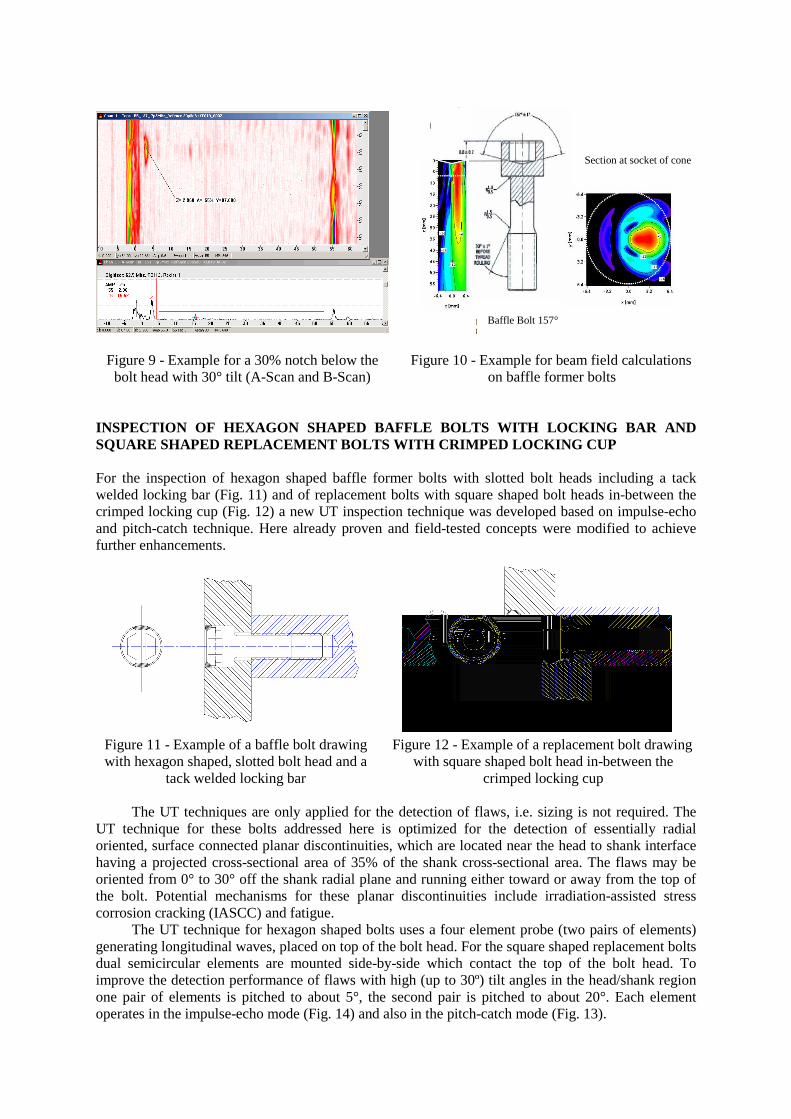
Figure 9 - Example for a 30% notch below the bolt head with 30° tilt (A-Scan and B-Scan)
Figure 10 - Example for beam field calculations on baffle former bolts
INSPECTION OF HEXAGON SHAPED BAFFLE BOLTS WITH LOCKING BAR AND SQUARE SHAPED REPLACEMENT BOLTS WITH CRIMPED LOCKING CUP
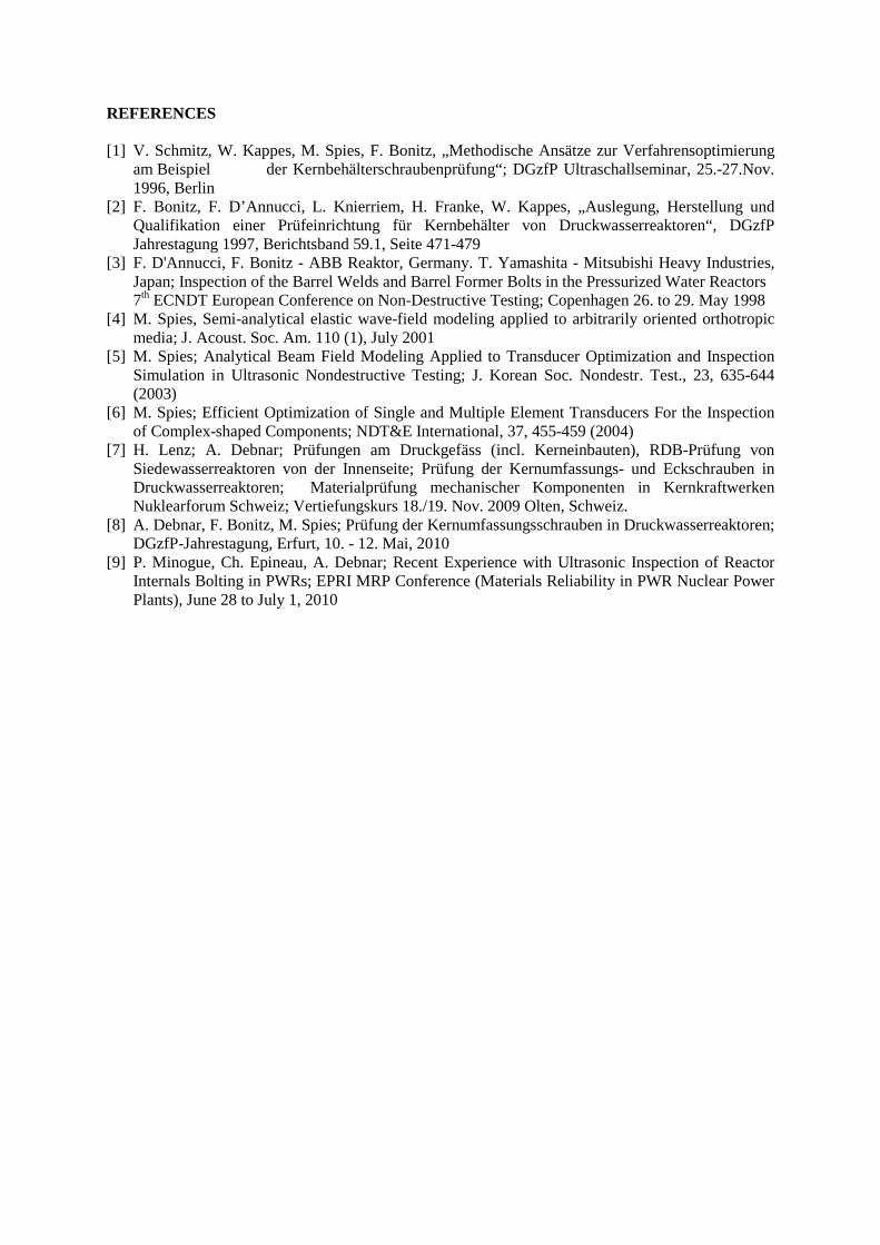
For the inspection of hexagon shaped baffle former bolts with slotted bolt heads including a tack welded locking bar (Fig. 11) and of replacement bolts with square shaped bolt heads in-between the crimped locking cup (Fig. 12) a new UT inspection technique was developed based on impulse-echo and pitch-catch technique. Here already proven and field-tested concepts were modified to achieve further enhancements.
Figure 11 - Example of a baffle bolt drawing with hexagon shaped, slotted bolt head and a
tack welded locking bar
Figure 12 - Example of a replacement bolt drawing with square shaped bolt head in-between the
crimped locking cup The UT techniques are only applied for the detection of flaws, i.e. sizing is not required. The
UT technique for these bolts addressed here is optimized for the detection of essentially radial oriented, surface connected planar discontinuities, which are located near the head to shank interface having a projected cross-sectional area of 35% of the shank cross-sectional area. The flaws may be oriented from 0° to 30° off the shank radial plane and running either toward or away from the top of the bolt. Potential mechanisms for these planar discontinuities include irradiation-assisted stress corrosion cracking (IASCC) and fatigue.
The UT technique for hexagon shaped bolts uses a four element probe (two pairs of elements) generating longitudinal waves, placed on top of the bolt head. For the square shaped replacement bolts dual semicircular elements are mounted side-by-side which contact the top of the bolt head. To improve the detection performance of flaws with high (up to 30º) tilt angles in the head/shank region one pair of elements is pitched to about 5°, the second pair is pitched to about 20°. Each element operates in the impulse-echo mode (Fig. 14) and also in the pitch-catch mode (Fig. 13).
Baffle Bolt 157°
Section at socket of cone

It is also to operate all elements in the receive mode when any transducer is pulsed. Each pair of transducers is configured to oppose each other along a centerline passing through the bolt centerline. A pair of elements acting in this mode has been utilized for baffle bolt inspection by Westinghouse since the late 1990’. The examinations are implemented using the UT endeffector attached to the SUPREEM ROSA V manipulator. Data collection and analysis are accomplished using the PARAGON UT Data Acquisition and Analysis System.
Figure 13 - UT probe design
with pitch-catch mode Figure 14 - UT probe design with impulse-echo mode
INSPECTION EXPERIENCES AND QUALIFICATION
The inspection of the baffle former bolts with inner hexagon bolt heads was developed for the inspection of baffle former bolts in NPPs in Switzerland. The inspection system using the MIDAS VI mini-submarine as manipulator was presented within a Practical Demonstration and was ENIQ-qualified on blind test specimen in July 2009.
The technique for the inspection of hexagon shaped baffle former bolts with slotted bolt heads including a tack welded locking bar and of replacement bolts with square shaped bolt heads in-between the crimped locking cup was ENIQ-qualified for France in April 2009 within a multi-phase qualification program.
The final qualification phase was completed in April, 2009 and involved: • complete system set-up and check-out from a packed condition, • equipment installation into a full scale underwater mockup, • inspection of 200+ bolts of various types which were installed into the mockup, • blind analysis of the data and recording/reporting per site field procedures, • equipment tear-down and packing. Since then four inspection campaigns were performed in France.
REFERENCES
[1] V. Schmitz, W. Kappes, M. Spies, F. Bonitz, „Methodische Ansätze zur Verfahrensoptimierung am Beispiel der Kernbehälterschraubenprüfung“; DGzfP Ultraschallseminar, 25.-27.Nov. 1996, Berlin
[2] F. Bonitz, F. D’Annucci, L. Knierriem, H. Franke, W. Kappes, „Auslegung, Herstellung und Qualifikation einer Prüfeinrichtung für Kernbehälter von Druckwasserreaktoren“, DGzfP Jahrestagung 1997, Berichtsband 59.1, Seite 471-479
[3] F. D'Annucci, F. Bonitz - ABB Reaktor, Germany. T. Yamashita - Mitsubishi Heavy Industries, Japan; Inspection of the Barrel Welds and Barrel Former Bolts in the Pressurized Water Reactors 7th ECNDT European Conference on Non-Destructive Testing; Copenhagen 26. to 29. May 1998
[4] M. Spies, Semi-analytical elastic wave-field modeling applied to arbitrarily oriented orthotropic media; J. Acoust. Soc. Am. 110 (1), July 2001
[5] M. Spies; Analytical Beam Field Modeling Applied to Transducer Optimization and Inspection Simulation in Ultrasonic Nondestructive Testing; J. Korean Soc. Nondestr. Test., 23, 635-644 (2003)
[6] M. Spies; Efficient Optimization of Single and Multiple Element Transducers For the Inspection of Complex-shaped Components; NDT&E International, 37, 455-459 (2004)
[7] H. Lenz; A. Debnar; Prüfungen am Druckgefäss (incl. Kerneinbauten), RDB-Prüfung von Siedewasserreaktoren von der Innenseite; Prüfung der Kernumfassungs- und Eckschrauben in Druckwasserreaktoren; Materialprüfung mechanischer Komponenten in Kernkraftwerken Nuklearforum Schweiz; Vertiefungskurs 18./19. Nov. 2009 Olten, Schweiz.
[8] A. Debnar, F. Bonitz, M. Spies; Prüfung der Kernumfassungsschrauben in Druckwasserreaktoren; DGzfP-Jahrestagung, Erfurt, 10. - 12. Mai, 2010
[9] P. Minogue, Ch. Epineau, A. Debnar; Recent Experience with Ultrasonic Inspection of Reactor Internals Bolting in PWRs; EPRI MRP Conference (Materials Reliability in PWR Nuclear Power Plants), June 28 to July 1, 2010