recent advancements in mechanical characterisation of 3d ...recent advancements in mechanical...
TRANSCRIPT
REVIEW Open Access
Recent advancements in mechanicalcharacterisation of 3D woven compositesMohamed Nasr Saleh1* and Constantinos Soutis2
Abstract
Three dimensional (3D) woven composites have attracted the interest of academia and industry thanks to theirdamage tolerance characteristics and automated fabric manufacturing. Although much research has been conductedto investigate their out-of-plane “through thickness” properties, still their in-plane properties are not fully understoodand rely on extensive experimentation. To date, the literature lacks an inclusive summary of the mechanicalcharacterisation for 3D woven composites. Therefore, the objective of this paper is to provide a comprehensive reviewof the available research studies on 3D woven composites mechanical characterisation, with less emphasis on the out-of-plane response, but an in-depth review of the in-plane response “un-notched vs. notched”. The paper highlights theknowledge gap in the literature of 3D woven composites, suggesting opportunities for future research in this field anda room for improvement in utilising Non-Destructive Techniques (NDT), such as Digital Image Correlation (DIC),Acoustic Emission (AE) and X-ray Computed Tomography (CT), for observing damage initiation and evolution in 3Dwoven composites that could be used to calibrate and evaluate analytical and numerical models.
Keywords: 3D textile composites, Mechanical properties, Damage mechanics
IntroductionTwo-dimensional (2D) laminated composites are charac-terised by their in-plane high specific stiffness andstrength (Ansar et al. 2011). However, many real lifeapplications are exposed to out-of-plane loading condi-tions that make it impossible to resort to the 2D laminatesas the proper solution. Wind turbine blades, stringers andstiffeners in aircraft, pressure vessels and construction ap-plications are some examples of applications in which out-of-plane loading conditions are imposed on the structure.Thus, the need for composite materials with enhancedthrough-thickness “out-of-plane” properties has emerged.This need requires replacing 2D laminated compositeswith three-dimensional (3D) textile structures in whichbinding/stitching yarns are introduced in the z-direction.The “enhanced out-of-plane properties” is not the onlyadvantage of 3D composites. The delamination resistance,due to the use of z-binders, enhances the impact perform-ance and damage tolerance of such material systems(Mcclain et al. 2012). In addition, using textile technology
can be utilised to manufacture near-net-shape preformswhich reduces the manufacturing/machining cost andtime even further. Although various techniques exist formanufacturing 3D textile preforms such as stitching,braiding, weaving and knitting, the most widely used now-adays is weaving due to its high production rate alongwith the ability to produce various 3D woven structures(Ansar et al. 2011).Generally, 3D woven composites can be divided into two
main groups depending on how deep the binder penetratesthrough the fabric. If it penetrates all the way through thethickness it is referred to as through-thickness (TT) inter-lock (see Fig. 1a, c) while it is classified as layer-to-layer(LTL) if the binder only holds adjacent layers (see Fig. 1b).Then this classification is further divided according to theinterlacing angle of the structure. The first category is theangle interlock (AI) in which the interlacing angle betweenthe binder and weft yarns can have any value except 90°(Fig. 1c). The second category is a special case of the firstone. The orthogonal interlock (ORT) (Fig. 1a) occurs whenthe interlacing angle between the binder and weft yarns isequal to 90° (Ansar et al. 2011).The weave pattern used during the weaving process can
also affect the classification of 3D woven composites. For
* Correspondence: [email protected] Manufacturing Research Centre with Boeing, University ofSheffield, S60 5TZ, Rotherham, UKFull list of author information is available at the end of the article
© The Author(s). 2017 Open Access This article is distributed under the terms of the Creative Commons Attribution 4.0International License (http://creativecommons.org/licenses/by/4.0/), which permits unrestricted use, distribution, andreproduction in any medium, provided you give appropriate credit to the original author(s) and the source, provide a link tothe Creative Commons license, and indicate if changes were made.
Saleh and Soutis Mechanics of Advanced Materialsand Modern Processes (2017) 3:12 DOI 10.1186/s40759-017-0027-z

instance in the case of ORT weave, the frequency of the z-binder sweeping the top and bottom surfaces of the weavecan vary from plain (Fig. 2a) to twill (Fig. 2b) or satin (Fig. 2c)pattern. This will directly affect the unit-cell size, degree ofcrimp, elastic response and damage/delamination resistanceas it will be highlighted later in this paper.From an industrial point of view, 3D woven LTL and AI
architectures have been used in applications where load isrequired to be transferred around a bend such as brackets,curved beams and T-shaped profiles (Redman et al. 2014).In such applications, the developed architectures were re-ported to demonstrate more resistance to the interlaminarshear and radial stresses developed in service. In Automotiveindustries, LTL woven composite was used to replace thehigh-strength steel (HSST) beams (Bayraktar et al. 2015). Inaddition, McClain et al. (Mcclain et al. 2012) reported suc-cessful usage of LTL and AI architectures in truss beamswith integral off-axis stiffeners as well as stiffened panels inwhich continuous fibres run from the skin into each stiffen-ing element. In this way, the need for fasteners and bonds atjoints is overcome which is one of the major challengesfacing 2D laminated composites nowadays. ORT architec-ture has been successfully used in the LEAP project tomanufacture fan blades and engine casings for A320neo,Comac C919 and 737-MAX as well as fuselage barrelstringers on long-range aircraft (Jewell et al. 2011). Another
interesting application of ORT carbon fibre architectureswas reported by Hemrick et al. (Hemrick et al. 2011) inultra-light weight heat exchangers for vehicle radiators. Theapplication made use of the high thermal conductivity ofORT architecture as the through-thickness binder creates aconduction path for the heat dissipation, In addition, Sharpet al. (Sharp et al. 2013) and Mohamed et al. (Mohamedand Wetzel 2006) have reported the usage of ORT architec-ture in wind turbine rotor blade applications. The conceptwas to integrate Π-joints with I-beam joints to connect theshear web and the spar cap in order to resist delaminationand improve the damage tolerance of the blade.In spite of the previously mentioned advantages of 3D
composite preforms, still their applications are limited (Tonget al., 2009a; Warren et al. 2015a). One of the main reasonsis the level of knowledge required to control the manufactur-ing process parameters. During the resin infusion process, itis essential and challenging, at the same time, to make surethat the resin has the ability to reach all the intricate locationsin the 3D complex woven architecture in order not to havevoids in the manufactured part. On the other hand, theremay be regions of resin rich pockets in the manufacturedcomposite. Many parameters affect the quality of the pro-duced component such as the resin viscosity, the 3D wovencomposite architecture and the mould design. This requires aproperly designed and controlled environment during the
Fig. 1 Types of 3D woven composites based on the binder path: (a) ORT, (b) LTL, (c) AI
Fig. 2 Examples of possible weave patterns for ORT: (a) Plain, (b) Twill, (c) Satin
Saleh and Soutis Mechanics of Advanced Materials and Modern Processes (2017) 3:12 Page 2 of 17
infusion process. Additional manufacturing defects can be inthe form of fibre breakage, in-plane fibre distortion or z-binder fibre distortion. Tong reports a comprehensive studyabout the manufacturing defects and their possible causes(Tong et al., 2009b). In addition to the manufacturingchallenges, 3D woven composites are characterised by lowerin-plane properties compared to those of 2D laminated com-posites. This is due to the fibres’ undulation or “crimp”caused by the interlacement of the longitudinal “warp” fibres,transverse “weft” fibres and z-binding fibres “binder” (Stig2012). The influence of the crimp on the in-plane propertieswas studied by Stig (Stig and Hallström 2013). So, it is alwaysa trade-off between the enhanced out-of-plane propertiesand the reduced in plane properties. This is an open area foroptimising 3D woven composites according to specific appli-cations. One last concern regarding 3D woven composites isto understand their mechanical behaviour in the elastic re-gion; but more importantly when damage occurs. Althoughquite a reasonable amount of research has been done in thisfield, still more experimental work has to be carried out be-fore expanding in the usage of 3D woven composites in en-gineering applications.To date, the literature lacks a comprehensive summary of
the mechanical characterisation work done for 3D wovencomposites. Therefore, the objective of this paper is to pro-vide as much detailed and comprehensive review of theavailable research studies on 3D woven composites mech-anical characterisation, with less emphasis on the out-of-plane response, but an in-depth review of the in-plane re-sponse “un-notched vs. notched”. This paper is designedpurely to address the advancement in experimental charac-terisation of 3D woven composites, but not the modellingaspect as it has been previously reviewed by Ansar et al.(Ansar et al. 2011). Section 2 will briefly discuss some ofthe previous studies of out-of-plane characterisation of 3Dwoven composites including impact/indentation, flexuraland interlaminar shear strength (ILSS) testing. A compre-hensive review of the un-notched in-plane response is thendetailed in section 3 for both on-axis and off-axis orienta-tions. Then, section 4 is dedicated to the notched responseof 3D woven composites again for, on-axis and off-axis,open-hole tension and bearing strength testing. Finally, sec-tion 5 highlights the concluding remarks of this review andsummarises in a tabulated format the different studies avail-able in the literature for the different weaving architecture“ORT, LTL and AI”.
Out-of-plane properties characterisationImpact/indentation testingAs the main advantage of 3D woven composites is clearlytheir out-of-plane enhanced properties, many researchersfor example (Ji et al. 2007; Luo et al. 2007; Hao et al. 2008;Walter et al. 2009; Gerlach et al. 2012; Seltzer et al. 2013;Umer et al. 2016) studied the effect of the z-binding yarns
on the impact damage behaviour and the energy absorp-tion of those material systems. Impact testing in literaturewas classified based on the impact velocity to low (<10 m/s) as reported in (Umer et al. 2016), high (~20 to50 m/s) as in (Ji et al. 2007; Hao et al. 2008) and ballistic(~900 m/s) as discussed in (Walter et al. 2009). Hao et al.(Hao et al. 2008) studied the behaviour of ORT wovenglass fibre composite plate and T-beams subjected toquasi-static indentation and impact loadings. Globalresponse in the form of load displacement and energyabsorption curves was evaluated, and Finite ElementModelling (FEM) results were validated against them. Theimplemented model correlated well with their experimen-tal findings. In addition, damage mechanisms in the caseof the T-beam and the plate were compared. Theyreported higher energy absorption by the T-beam as op-posed to the composite plate, for the same loading level.Another study by Ji et al. (Ji et al. 2007) investigated thequasi-static indentation and impact behaviour of a circularplate made of ORT woven glass fibre composite. Thequasi-static indentation test was carried out using a MTSmachine while the impact test was done using a modifiedsplit Hopkinson pressure bar apparatus. The damaged sur-faces of the specimens were characterised afterwards andenergy absorption was calculated to verify FEM modelsthey produced. Luo et al. (Luo et al. 2007) carried outquasi-static indentation and transverse impact tests forORT hybrid woven composites with aramid and glass fibreyarns. The focus of this study was the strain rate sensitiv-ity effect on energy absorption. It was reported that thehigher the impact velocity (20, 40, 55 m/s), the higher theenergy absorbed (~ 8, 12, 18 J) by the composite. Regard-ing the damage/failure mechanisms, the quasi-staticloaded specimens suffered from tensile failure on the bot-tom side and compressive failure on the top side. In thecase of impact damage, three damage mechanisms werecaptured: matrix cracking, fibre breakage and fibres pull-out. In contrast to the response of the laminated compos-ites, the effect of the through-thickness binder was signifi-cant as it supressed the delamination. An interesting studyby Seltzer et al. (Seltzer et al. 2013) revealed the damagemechanisms of 3D S2-glass, carbon and hybrid wovencomposites by X-ray Computed Tomography (CT) due tolow-velocity impact. In addition, they compared the en-ergy absorption of the 3D woven composites with that of2D laminated counterparts. They reported that the energyabsorbed by the 3D woven composites was approximatelytwice the energy absorbed by the 2D laminated composite.The X-ray images demonstrated that this higher energyabsorption was due to the binding yarns delaying thedelamination and providing integrity to the structure. Theexistence of binding yarns resulted in dissipating the en-ergy by other damage mechanisms such as tow splitting,out-of-plane shear and extensive fibre breakage.
Saleh and Soutis Mechanics of Advanced Materials and Modern Processes (2017) 3:12 Page 3 of 17
Flexural & interlaminar shear strength testingThe effect of z-binding yarns on the flexural and inter-laminar shear strength of 3D woven composites hasbeen studied by (Chou et al. 1992; Cox et al. 1994; Wang2006; Tong et al., 2009b; Walter et al. 2010; Nasution etal. 2014; Behera and Dash 2015; Dai et al. 2015a; Umeret al. 2016; Labanieh et al. 2017). For ORT and 3D braidedarchitecture, Wang et al. (Wang 2006) reported both theflexural “3-point bending” and ILSS responses. Failuremodes for flexural testing were a combination of tensileand compressive failure modes with the tensile modes be-ing more significant. Authors mentioned clearly that theshort-beam test could not be considered as a valid meas-ure of the ILSS of 3D woven composites as they wouldnot fail in shear. The calculated shear at failure was re-ferred to as “apparent interlaminar shear strength” whichrepresented a lower bound for the interlaminar shearstrength as specimens failed due to bending instead. How-ever, authors claimed that failure due to interlaminar shearmight have occurred prior to the bending failure.Following this study, Tong et al. (Tong et al., 2009b) re-
ported that flexure properties “modulus/strength” of 3Dwoven composites were found to be inferior to 2D lami-nates. With regards to the interlaminar shear short beamtest, they reported, in a single graph, the normalised inter-laminar shear strength versus the z-binder volume fractionreported in previous studies. In some cases, a slight im-provement in the ILSS properties was observed although inmost cases no significant change was reported. On the con-trary, Walter et al. (Walter et al. 2010) concluded in hisstudy that 3D woven composites “ORT & AI” tested in theshort-beam configuration exhibited lower interlaminarshear strength when compared to 2D plain woven lami-nated composite as a baseline. It is useful for the discussionto highlight here that the first drop in the load is normallyused to calculate the ILSS which may be misleading in thecase od 3D woven composites. As the z-binding yarnscause higher crimp and stress concentrations, this acceler-ates the first damage to occur corresponding to the firstload drop. However, the same z-binding yarns help resistingdelamination and crack propagation leading to higher strainto failure of 3D woven composites compared to their 2Dcounterparts. This was supported by optical microscopy inthis study revealing that delamination cracks were arrestedby the z-binding yarns in the case of ORT leading to ahomogenously distributed damage and different non-linearresponse compared to the baseline 2D architecture. Thisdemonstrated the damage tolerance capabilities of 3Dwoven composites.For better understanding of the damage evolution in
quasi-static flexural testing, Umer et al. (Umer et al. 2016)utilised X-ray CT scans of the failed specimens after testing.Three different architectures “ORT, LTL, AI” were testedalong the warp and weft directions. A significant difference
between the weft and warp modulus (~1.7) and strength(~1.4) was attributed to the higher fibre volume fraction inthe weft compared to the warp for LTL architecture. Thiseffect was less in the case of ORT (~1.14) and AI (~1.1) inwhich the difference between the fibre volume fraction inthe weft and warp was not significant. X-ray CT scans re-vealed that damage initiated at resin-rich areas and aroundthe z-binding yarns. Authors reported that cracks propaga-tion followed the z-binder yarns leading to final failure.Labanieh et al. (Labanieh et al. 2017) has recently investi-gated the effect of adding biased layers (+θ°/−θ°) to classicalORT architecture on the interlaminar shear response usingshort-beam testing configuration. The two multiaxial ORTarchitectures were different from the stacking sequencepoint of view. One of them (referred to as IMA) had thebiased layers (+θ°/−θ°) adjacent to each other while theywere separated by a 0° layer in the second architecture (re-ferred to as MA). Digital Image Correlation (DIC) was usedto obtain full strain field across the thickness of the speci-mens during testing. Locations of macroscopic cracks initi-ation were captured and analysed successfully. For all thetested architectures, the z-binding yarns reduced the delam-ination growth. In addition, authors concluded that insertionof the biased layers, especially in the case of the MA archi-tecture, improved the delamination resistance compared toa classical ORT architecture. This was justified by the reduc-tion of the relative angle between successive yarn layers.
Un-notched in-plane properties characterisationIn this section, the un-notched in-plane characterisation of3D woven composites is reviewed in detail. As a conventionfor all the studies to be discussed, the “on-axis” terminologyrepresents the cutting orientation along the warp or theweft directions while the “off-axis” terminology refers to a45° cutting orientation as depicted in Fig. 3.
On-axisFor the in-plane properties’ characterisation, much workhas been done to characterise the failure mechanisms of 3Dwoven composites subjected to quasi-static loading (Cox etal. 1994, 1996; Pochiraju 1999; Leong et al. 2000; Tan et al.2000; Quinn et al. 2008; Lomov et al. 2011; Gerlach et al.2012; Visrolia and Meo 2013; Behera and Dash 2015; War-ren et al. 2015a; Dai et al. 2015a) along the warp- or weft-directions. An early study by Cox et al. (Cox et al. 1994,1996) studied the failure mechanisms of 3D woven com-posites (ORT, LTL) monotonically loaded in tension, com-pression and bending. They found that the dominantfailure modes in 3D interlock woven composites were towrupture and pull-out (tension case), delamination and kink-band formation (compression case), and a combination ofthose failure modes (bending case). Afterwards, Pochirajuand Chou (Pochiraju 1999) reported the behaviour of 3Dwoven composites (LTL, AI, Braided) under tension along
Saleh and Soutis Mechanics of Advanced Materials and Modern Processes (2017) 3:12 Page 4 of 17

the warp and weft directions. Moreover, compression testswere conducted using the IITRI test fixture, shear usingIosipescu fixture and bending using four-point fixture. Thestress-strain response for all the conducted testing and forthe various textile architectures was analysed and thefractured surfaces were investigated. Linear stress-strainresponse was reported when loaded along the warp andweft directions while non-linear response was observed inthe case of shear/off-axis loading. The study concluded thatresin rich regions and tow-matrix debonding at theinterface represented the weak and preferential path forfracture.For ORT woven composites manufactured out of glass
fibre (Ivanov et al. 2009; Lomov et al. 2009) or carbonfibre (Lomov et al. 2011; Bogdanovich et al. 2013), theystudied their mechanical response in tension as well asdamage initiation and progression using acoustic emission(AE) method both in the warp and weft directions. Forthe glass fibre case, a comprehensive comparison betweenORT woven composite and a 2D plain woven counterpartwas conducted. The study suggested that ORT wovencomposite had significantly higher ultimate tensilestrength and strain to failure. This superior response dem-onstrated the capability of the ORT woven composite insupressing delamination and damage tolerance as opposedto the 2D laminated composites manufactured out of thesame fibre type. The study was also supplemented withfull-strain maps using DIC analysis and micrographs tovisualise damage and cracking progression. In addition,light transparent images were used to trace the damageprogression throughout the mechanical test. In the case ofcarbon fibre ORT woven composite, the “as manufac-tured” internal geometry was scanned using X-ray CT toreveal any fabric distortion or voids due to the manufac-turing process. The X-ray CT technique was then used to
reveal the crack propagation and damage progressionduring testing. A clear classification of the different typesof damage mechanisms observed was tabulated in thestudy which was supported by the micrographs or theX-ray CT scans (see Table 1).The AE data suggested that the damage progression in
the case of warp loading is significantly different fromthe case of weft loading. The higher energy events in theweft loading direction was attributed to the higheramount of transverse cracking and local debonding aswell as the presence of undulated weft yarns on the sur-face layers of the composite. For the warp loaded ORTwoven composite in both studies, it was found that dam-age initiates firstly at binder interlacement points. It isthen followed by transverse cracks in yarns transverse tothe loading direction and local delamination betweenyarns. Final failure is characterised by fibre failure thatleads to complete rupture of the specimen.
Fig. 3 Schematic of specimens’ cutting orientation for in-plane testing
Table 1 Nomenclature of damage types in on-axis tension testbased on (Lomov et al. 2011a)
Code Damage type Direction
B Cracks on the boundaryof the yarns
Normal to the loadingdirection
T Transverse cracking within yarns Normal to the loadingdirection
L Debonding on yarns’ surface Parallel to the loadingdirection
Z Cracks on the boundary ofZ-binding yarns
Following the Z-bindingyarns surface
MT Transverse cracking in thematrix pockets
Normal to the loadingdirection
ML Longitudinal cracking in thematrix pockets
Parallel to the loadingdirection
Saleh and Soutis Mechanics of Advanced Materials and Modern Processes (2017) 3:12 Page 5 of 17

In an attempt to highlight the knowledge gap forthrough-thickness reinforced composites, Mouritz and Cox(Mouritz and Cox 2010) surveyed the available literature todetermine the effect of stitching, pinning and 3D weaving(ORT and AI) on the quasi-static (tension, compression,interlaminar shear) and fatigue response of compositematerials. According to their study, through-thicknessreinforcement either by z-binding yarns or stitching couldimprove the in-plane mechanical properties but not pin-ning. For pinning, the reduction of the in-plane propertieswas justified by the fact that fibre breakage/damage is moreprevalent in pinned composites compared to 3D wovenand stitched composites, although the percentage of fibresbroken by pinning has never been measured. For z-bindingand stitching, the enhancement in in-plane mechanicalproperties have been found to be typically less than 20% oftheir equivalent 2D laminate counterparts and independentfrom the fibre volume fraction or the size of the z-bindingyarns/ stitches. On the contrary, some other researchers re-ported a reduction in the in-plane mechanical properties of3D woven/ stitched composites which is usually less than20% as well. Mouritz and Cox tried to explain this contra-diction in the reported data from different researchers.They justified the improvement in the mechanical proper-ties by higher fibre volume fraction due to compaction ofthe 3D woven/stitched composites during the through-thickness reinforcement process. However, such an explan-ation could not be supported without correlating the in-plane mechanical properties to the fibre volume fractionand prove repeatability; which is something many re-searchers failed to report in their studies. On the contrary,the reduction of the in-plane mechanical properties couldbe attributed to the geometrical distortions and induced de-fects because of the through-thickness reinforcing processsuch as fibre waviness, undulation, voids and resin rich re-gions. Comprehensive quantitative analysis of the effect ofdefects on the mechanical properties and damage mecha-nisms of through-thickness reinforced composites is essen-tial to understand the behaviour of such material systems;which according to their study represents a knowledge gapthat limits the possibility of predicting the failure strengthof 3D woven and stitched composites.Gerlach et al. (Gerlach et al. 2012) studied AI woven
composites, with two different z-binder volume fractions3 and 6%, subjected to quasi static (3–4 × 10⁻³ mm.s−1),medium (85 mm.s−1) and high (11,000 mm.s−1) strainrates. The different loading conditions included tension(warp, weft), interlaminar shear, out-of-plane tension andcompression, 3-point bending and plate bending. Thepaper tackled various challenges faced during testing suchas developing appropriate test methods for out-of-planeproperties characterisation of 3D woven composites aswell as the scale effect when comparing the specimen’s di-mensions required for quasi-static and dynamic “medium/
high strain-rate” tests. Damage evolution for the differentconducted tests was characterised with an air-coupledUltrasound system, X-ray CT system and 3D opticalmicroscopy system. A summary of the experimental cam-paign and specimens’ dimensions is detailed in Table 2.The reader is referred to the original paper for detailedexperimentation procedure.The study concluded that the effect of z-binder volume
fraction on the in-plane properties was minor. However, itsignificantly affects the delamination resistance in the caseof plate bending. The paper provided some guidelines formodelling of 3D woven composites, based on a compre-hensive experimental campaign, which included accuratemodelling of the z-binder deformation and damage propa-gation as well as its effect on the delamination resistance ofthe 3D woven composite. Visrolia and Meo (Visrolia andMeo 2013) performed on-axis tension (0° direction), off-axis tension (45° direction) and compression tests to valid-ate their modelling strategy for ORT woven composites. Agood agreement of global stress/strain was demonstratedbetween their proposed model and the experimental re-sults, although for off-axis tension the experimental resultswere reported up to 3% strain only (not until failure) andthe damage mechanisms were not revealed.The influence of fabric architecture of 3D woven com-
posite on tensile, compressive and bending response wasinvestigated by Dai et al. (Dai et al. 2015a) only along thewarp direction. They focused mainly on ORT and AI ar-chitectures while varying the ORT pattern as 1-by-1 and3-by-3 weaves. Burn-off method was carried out to deter-mine the fibre volume fraction for all the six testedarchitectures. In addition, DIC was used during tensileloading to visualise the strain map on the surface whileoptical microscopy was used to reveal the quality of the“as manufactured” panels as well as the damage at failure.They found that the mechanical performance was affectedby resin rich regions and waviness of load-carrying fibres.The warp tow waviness measured for the differentarchitectures was in the range of (0.5 to ~3%). The lesswaviness in a specific architecture, the higher the modulusand strength measured experimentally. The reader isreferred to the original paper for detailed analysis.Moreover, one of their AI architecture outperformed
Table 2 Summary of the experimental testing carried out by(Gerlach et al. 2012)
Test type Specimen geometry Specimen dimensions
In-plane tension Dog-bone 70 × 10
Out-of-plane tension Cross 20 × 20
Shear Notched beam 25 × 20
Out-of-plane compression Cube 10 × 10
3-point bending Prism 60 × 10
Plate bending Plate 100 × 100
Saleh and Soutis Mechanics of Advanced Materials and Modern Processes (2017) 3:12 Page 6 of 17
other architectures for all loading conditions “tension,compression and flexure”, but it experienced the longestcrack delamination. Authors concluded that the delamin-ation length can be reduced by changing the binding se-quence to one with shorter binder spacing/ smaller unitcell size. No results along the weft direction or the off-axisdirection were reported in this study.Warren et al. (Warren et al. 2015a) characterised the
global stress-strain curves and failure modes of 3D twillharness ORT woven composites, two types of LTL wovencomposites and 2D quasi-isotropic woven architecturesubjected to warp and weft tensions. Optical microscopyimages revealed the “as manufactured” internal architec-ture of the various 3D woven composites in this study.Full field strain mapping up to failure was captured usingDIC. Results from DIC clearly showed the higher strainconcentrations in the matrix regions especially whenloaded along the weft direction; however no explanationfor this observation was provided. In case of LTL, a non-linear stress-strain response was observed and it was at-tributed to the higher crimp in the warp direction com-pared to the weft direction. A similar non-linear trend intension was also reported in (Callus et al. 1999; Leong etal. 2000; Rudov-Clark 2007; Labanieh et al. 2017). In-plane shear testing was also carried out using V-notchedrail shear method, where authors found that the shearamong adjacent tows and matrix degradation were thedominant damage mechanisms in shear leading to finalfailure. The effect of crimp on the compressive responsewas determined by defining the compressive warp-loadedstrength/stiffness normalised by the weft-loaded strength/stiffness. The tow waviness ratio was defined as the towwaviness in the weft tows divided by the tow waviness inthe warp tows. Authors suggested that tow waviness has asignificant effect on the mechanical performance of 3DLTL woven composites and adjusting tension during theweaving process can be controlled in the weft direction toadjust this tow waviness ratio and keep it closer to unity.One recent paper by Saleh et al. (Saleh et al. 2016b)
characterised the mechanical properties and the influenceof the z-binder of three different architectures of 3Dwoven composites (ORT, LTL, AI) both in the on-axis andoff-axis directions. In this study, resin film infusion (RFI)process (see Fig. 4) was utilised to wet the 3D woven fab-rics to produce the 3D woven composite plates.The study suggested that the z-binder affects void content
in 3D woven composites since the amount of resin flowingbetween warp and weft tows is partly inhibited by thebinders. As the RFI process does not have a flow medium toguide the resin during the infusion process, the z-bindingyarns in 3D woven composites guide the resin through thethickness of the 3D preform. Thus, ORT architecture in-duced the highest amount of void (~2.63%) followed by AI(~2.42%) and LTL (~1.63%) architectures as shown in Fig. 5.
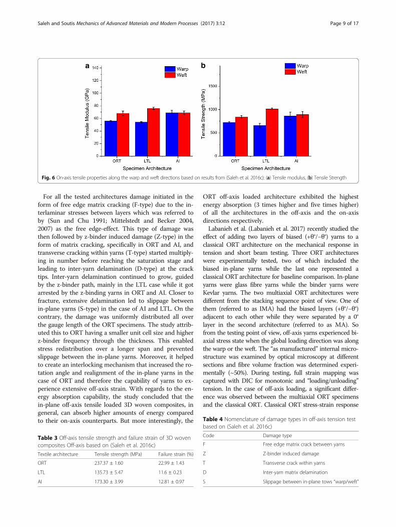
The study also concluded that regardless of the weav-ing architecture, the directional fibre volume fraction ofthe warp and weft directly affects the stiffness (Fig. 6a)and tensile strength (Fig. 6b) of 3D woven compositesunder on-axis loading. For instance, LTL architecturehad the highest fibre volume fraction in the weft direc-tion; so it demonstrated the highest modulus andstrength along the weft direction out of all the testedarchitectures. For the sake of comparison between theweft and warp responses/moduli in the light of thedirectional fibre volume fraction, the maximum
difference was clear in the case of LTL ( Eweft
Ewarp~ 1.42)
while it was less sound in the case of ORT ( Eweft
Ewarp~ 1.23)
and almost vanished for AI (Eweft
Ewarp~ 0.98).
One of the latest studies by (Castaneda et al. 2016)focused on the tensile response of ORT architecture alongthe warp/weft directions with the aim to understand theeffect of the z-binder on the mechanical response anddamage initiation as well as evolution coupled with DIC,AE and X-ray CT techniques. Both monotonic and fatigueuniaxial tension cases were studied. Using the DIC system,extensive strain localisation regions, corresponding tohigher strain, were captured at the “z-crown” regions andthe weft boundaries when loaded along the weft and warpdirections respectively. The “z-crowns” were defined asshort surface segments of z yarns oriented in warp direc-tion and laying over the weft yarns. These in-plane strainlocalisations were successfully correlated with the AEevents. Beside the in-plane strain localisations, out-of-planestrains “jumps” occurred locally at the “z-crown” spotswhich were associated with both local and global damageprogression. Cross sectional X-ray CT scans revealed themost dominant damage mechanisms which were classifiedas surface tow debonding, surface tow transverse crackingand inner tow debonding. The local surface tow debondingand transverse cracking were referred to as the cause of thelocal jump of the “z-crowns”. The study concluded that al-though the z-binders could cause out-of-plane effects/de-formation, they could still provide transverse reinforcementto 3D woven composites.It is worth mentioning at this point that some of the
work (Ivanov et al. 2009; Lomov et al. 2009; Bogdanovichet al. 2013; Visrolia and Meo 2013; Saleh et al. 2016b)discussing the on-axis testing has also investigated the off-axis biased loading of 3D woven composites as it will bedetailed in the following section.
Off-axisLimited work has been performed to characterise 3Dwoven composites under off-axis (45°) loading direction. Asmentioned earlier in the On-axis section, Lomov et al.(Ivanov et al. 2009; Lomov et al. 2009) have reported
Saleh and Soutis Mechanics of Advanced Materials and Modern Processes (2017) 3:12 Page 7 of 17

loading direction sensitivity (warp, weft, bias) of 3D wovencomposites but the materials were limited to ORT architec-ture. The focus on ORT architecture was justified by thefact that this type of architecture could demonstrate higherin-plane stiffness and strength than AI architecture owingto having more straight yarns in the plane of loading. Thestudy also compared the damage evolution of ORT against2D laminated composite. In addition, it was supplementedwith full-strain maps using DIC analysis and micrographsto visualise damage and cracking progression. Clear distinc-tion between the damage evolution in 2D and 3D wovencomposites was reported. In the case of 2D laminate, dam-age started in the form of transverse cracks within both thewarp and weft yarns. These transverse cracks multiply upto a saturation stage at which local delamination at cracktips was observed. Closer to failure, extensive delaminationand “scissoring” effect due to warp and weft realignmentled to large shear stresses/strains. Damage for ORT archi-tecture was first observed at the interlacement points withthe binder which was referred to in the paper as “z-crown”regions. This type of damage was described as repeatedsmall micro-cracks homogenously distributed across thespecimen. They acted as “trellis hinges” around which thewarp and weft yarns try to rotate/realign. Afterwards, thosecracks penetrated to the matrix pockets forming shear
cracks in the neighbouring z yarns. Then, several shearcracks within the warp and weft yarns were observed beforereaching the state of extensive transverse cracking and localdebonding between in-plane yarns close to final failure.Following this work, the study by (Saleh et al. 2016b)
has demonstrated the need to determine the loading dir-ection sensitivity of various architectures of 3D wovencomposites subjected to warp, weft and bias loadings.The relationship between damage mechanisms and en-ergy absorption up to failure was revealed. In addition toinvestigating the on-axis loading direction response ashighlighted in the previous section, the study conducteda detailed examination of the off-axis response of threedifferent 3D woven architectures namely ORT, LTL andAI. X-ray CT technique was used to characterise damageinitiation and evolution during testing. The off-axisstress-strain response demonstrated that out of all thetested architectures, ORT exhibited the best perform-ance in terms of the highest failure strength and failurestrain as opposed to AI and LTL (see Table 3).Capturing the damage evolution in the off-axis direction
using X-ray CT scans helped in understanding the reasonbehind the different response of the ORT, LTL and AI archi-tectures. The study used the nomenclature listed in Table 4to easily describe the various damage mechanisms observed.
Fig. 4 Resin Film Infusion to manufacture 3D woven composite panels by Saleh et al.: (a) Schematic and (b) vacuum bag layup
Fig. 5 Results of the volume fraction analysis measured experimentally by (Saleh et al. 2016c)
Saleh and Soutis Mechanics of Advanced Materials and Modern Processes (2017) 3:12 Page 8 of 17
For all the tested architectures damage initiated in theform of free edge matrix cracking (F-type) due to the in-terlaminar stresses between layers which was referred toby (Sun and Chu 1991; Mittelstedt and Becker 2004,2007) as the free edge-effect. This type of damage wasthen followed by z-binder induced damage (Z-type) in theform of matrix cracking, specifically in ORT and AI, andtransverse cracking within yarns (T-type) started multiply-ing in number before reaching the saturation stage andleading to inter-yarn delamination (D-type) at the cracktips. Inter-yarn delamination continued to grow, guidedby the z-binder path, mainly in the LTL case while it gotarrested by the z-binding yarns in ORT and AI. Closer tofracture, extensive delamination led to slippage betweenin-plane yarns (S-type) in the case of AI and LTL. On thecontrary, the damage was uniformly distributed all overthe gauge length of the ORT specimens. The study attrib-uted this to ORT having a smaller unit cell size and higherz-binder frequency through the thickness. This enabledstress redistribution over a longer span and preventedslippage between the in-plane yarns. Moreover, it helpedto create an interlocking mechanism that increased the ro-tation angle and realignment of the in-plane yarns in thecase of ORT and therefore the capability of yarns to ex-perience extensive off-axis strain. With regards to the en-ergy absorption capability, the study concluded that thein-plane off-axis tensile loaded 3D woven composites, ingeneral, can absorb higher amounts of energy comparedto their on-axis counterparts. But more interestingly, the
ORT off-axis loaded architecture exhibited the highestenergy absorption (3 times higher and five times higher)of all the architectures in the off-axis and the on-axisdirections respectively.Labanieh et al. (Labanieh et al. 2017) recently studied the
effect of adding two layers of biased (+θ°/−θ°) yarns to aclassical ORT architecture on the mechanical response intension and short beam testing. Three ORT architectureswere experimentally tested, two of which included thebiased in-plane yarns while the last one represented aclassical ORT architecture for baseline comparison. In-planeyarns were glass fibre yarns while the binder yarns wereKevlar yarns. The two multiaxial ORT architectures weredifferent from the stacking sequence point of view. One ofthem (referred to as IMA) had the biased layers (+θ°/−θ°)adjacent to each other while they were separated by a 0°layer in the second architecture (referred to as MA). Sofrom the testing point of view, off-axis yarns experienced bi-axial stress state when the global loading direction was alongthe warp or the weft. The “as manufactured” internal micro-structure was examined by optical microscopy at differentsections and fibre volume fraction was determined experi-mentally (~50%). During testing, full strain mapping wascaptured with DIC for monotonic and “loading/unloading”tension. In the case of off-axis loading, a significant differ-ence was observed between the multiaxial ORT specimensand the classical ORT. Classical ORT stress-strain response
Fig. 6 On-axis tensile properties along the warp and weft directions based on results from (Saleh et al. 2016c): (a) Tensile modulus, (b) Tensile Strength
Table 3 Off-axis tensile strength and failure strain of 3D wovencomposites Off-axis based on (Saleh et al. 2016c)
Textile architecture Tensile strength (MPa) Failure strain (%)
ORT 237.37 ± 1.60 22.99 ± 1.43
LTL 135.73 ± 5.47 11.6 ± 0.23
AI 173.30 ± 3.99 12.81 ± 0.97
Table 4 Nomenclature of damage types in off-axis tension testbased on (Saleh et al. 2016c)
Code Damage type
F Free edge matrix crack between yarns
Z Z-binder induced damage
T Transverse crack within yarns
D Inter-yarn matrix delamination
S Slippage between in-plane tows “warp/weft”
Saleh and Soutis Mechanics of Advanced Materials and Modern Processes (2017) 3:12 Page 9 of 17
was significantly non-linear compared to the two multiaxialcounter parts with much higher strain to failure and muchlower strength. This distinguished behaviour of theclassical ORT was attributed to the absence of reinforcingfibres along this off-axis (45°) loading direction. Modulusdegradation due to damage evolution was measuredthrough the “loading/unloading” tensile test in the warp,weft and off-axis direction and recommended by theauthors for incorporation in modelling the effect ofdamage in 3D woven composites. The reader is referredto the original article for extensive discussion of ILSS dataof the specified architectures.
Notched characterisationOpen-hole tensionOn-axisThe scope of previous studies in the literature has beendedicated to evaluating the effect of notches on thestrength, fracture toughness, damage and failure mecha-nisms of both laminated (Awerbuch and Madhukar 1985;Callus 2007) and 2D woven composites (Yudhanto et al.2012a, b). It was observed that the undulating nature ofthe woven fabric improves the delamination and splittingresistance compared to 2D laminates as it helped in pre-venting crack propagation within the matrix and acted ascrack stoppers. Thus, the notched strength of the 2Dwoven laminates was reported to be higher than the lami-nated composites. In other words, 2D woven compositeswere found to be less notch sensitive (Naik et al. 1990;Shembekar and Naik 1992). Replacing 2D with 3D wovencomposites helped in achieving further enhancement ofthe notched strength and fracture toughness, along thefibre direction, of composites as reported in (Cox et al.1996; Tsai et al. 2000). The effect of the through-thicknessbinder in 3D woven composites was clearly observed as adramatic decrease in the notch sensitivity of 3D wovencomposites and significant improvement of the fracture
toughness and damage tolerance compared with those of2D woven laminates.Recently, Dai et al. (Dai et al. 2015b), investigated the
notch sensitivity of carbon fibre reinforced polymers(CFRP) ORT and AI woven composites tested in quasi-static tension and tension-tension fatigue. The scope ofboth tests was the on-axis loading either along the warpor the weft direction. For quasi-static testing, DIC wasused to monitor the damage evolution up to failure whilean infra-red camera was used in the case of fatigue testingto monitor the development of fatigue damage. To ad-dress the effect of the notch size on the notched responseof 3D woven composites, two hole sizes with a diameterto width ratio of 1/6 and 1/2 respectively were tested. Thestudy concluded that regardless of the hole size, the reduc-tion in the strength of the investigated architectures didnot exceed 17% compared to the un-notched strength inthe case of on-axis loading. Although 3D woven compos-ites tested along the warp or weft directions have beenproven to be relatively notch insensitive (Mubeen 2014;Dai et al. 2015b), there is very limited literature reportingthe behaviour/sensitivity of 3D woven composites loadedalong the off-axis direction exists.
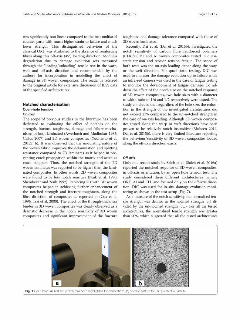
Off-axisOnly one recent study by Saleh et al. (Saleh et al. 2016a)reported the notched response of 3D woven composites,in off-axis orientation, by an open hole tension test. Thestudy considered three different architectures namelyORT, AI and LTL and focused only on the off-axis direc-tion. DIC was used for in-situ damage evolution moni-toring as shown in the test setup (Fig. 7).As a measure of the notch sensitivity, the normalised ten-
sile strength was defined as the notched strength (σn) di-vided by the un-notched strength (σun). For all the testedarchitectures, the normalised tensile strength was greaterthan 90%, which suggested that all the tested architectures
Fig. 7 Open hole: (a) Test setup “hole has been highlighted for clarification”, (b) Speckle pattern for DIC (Saleh et al. 2016b)
Saleh and Soutis Mechanics of Advanced Materials and Modern Processes (2017) 3:12 Page 10 of 17
were relatively notch insensitive (see Table 5) compared tothe ideally ductile “notch insensitive” curve defined in Eq. 1.
σn=σun ¼ 1− d=wð Þ ð1Þ
where:(σn) : The notched tensile strength(σun) : The un-notched tensile strength(d) : The hole diameter(w) : The specimen widthThe final failure of the 3D woven architectures “corre-
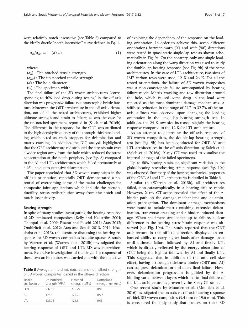
sponding to 40% load drop during testing” in the off-axisdirection was progressive failure not catastrophic brittle frac-ture. Moreover, the ORT architecture in the off-axis orienta-tion, out of all the tested architectures, exhibited higherultimate strength and strain to failure, as was the case forthe un-notched specimens reported in (Saleh et al. 2016b).The difference in the response for the ORT was attributedto the high density/frequency of the through-thickness bind-ing which acted as crack stoppers for delamination andmatrix cracking. In addition, the DIC analysis highlightedthat the ORTarchitecture redistributed the stress/strain overa wider region away from the hole which reduced the stressconcentration at the notch periphery (see Fig. 8) comparedto the AI and LTL architectures which failed prematurely ata 45° line due to extensive delamination.The paper concluded that 3D woven composites in the
off-axis orientation, especially ORT, demonstrated a po-tential of overcoming some of the major challenges forcomposite joint applications which include the pseudo-ductility, stress redistribution away from the notch andnotch insensitivity.
Bearing strengthIn spite of many studies investigating the bearing responseof 2D laminated composites (Kelly and Hallström 2004;Thoppul et al. 2009; Pisano and Fuschi 2011; Atas 2012;Öndürücü et al. 2012; Ataş and Soutis 2013, 2014; Kha-shaba et al. 2013), the literature discussing the bearing re-sponse for 3D woven composites is quite sparse. A studyby Warren et al. (Warren et al. 2015b) investigated thebearing response of ORT and LTL 3D woven architec-tures. Extensive investigation of the single-lap response ofthese two architectures was carried out with the objective
of exploring the dependency of the response on the load-ing orientation. In order to achieve this, seven differentorientations between warp (0°) and weft (90°) directionswere tested in quasi-static single-lap test as shown sche-matically in Fig. 9a. On the contrary, only one single load-ing orientation along the warp direction was used to studythe double-lap bearing response (see Fig. 9b) of the samearchitectures. In the case of LTL architecture, two sizes ofIM7 carbon tows were used; 12 K and 24 K. For all thetested orientations, the failure of 3D woven compositeswas a non-catastrophic failure accompanied by bearingfailure mode. Matrix cracking and tow distortion aroundthe hole, which caused some drop in the load werereported as the most dominant damage mechanisms. Astiffness reduction in the range of 24.7 to 32.7% of the on-axis stiffness was observed upon changing the loadingorientation in the single-lap bearing strength test. Inaddition, the 24 K tow size increased slightly the bearingresponse compared to the 12 K for LTL architecture.As an attempt to determine the off-axis response of
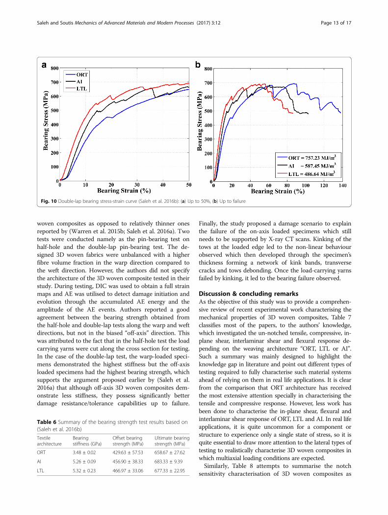
3D woven composites, the double-lap bearing strengthtest (see Fig. 9b) has been conducted for ORT, AI andLTL architectures in the off-axis direction by Saleh et al.(Saleh et al. 2016a). X-ray CT was used to visualise theinternal damage of the failed specimens.Up to 50% bearing strain, no significant variation in the
global bearing stress/bearing strain response (see Fig. 10a)was observed. Summary of the bearing mechanical propertiesof the ORT, AI and LTL architectures is detailed in Table 6.Similar to (Warren et al. 2015b), all architectures
failed, non-catastrophically, in a bearing failure mode.However, X-ray CT scans revealed the effect of the z-binder path on the damage mechanisms and delamin-ation propagation. The dominant damage mechanismswere found to include matrix crushing, extensive delam-ination, transverse cracking and z-binder induced dam-age. When specimens are loaded up to failure, a cleardifference in the bearing stress/strain response was ob-served (see Fig. 10b). The study reported that the ORTarchitecture in the off-axis direction displayed an en-hanced ability to carry higher loads after damage onsetuntil ultimate failure followed by AI and finally LTLwhich is directly reflected by the energy absorption ofORT being the highest followed by AI and finally LTL.This suggested that in addition to the unit cell sizeeffect, having a through-thickness binder (ORT and AI)can suppress delamination and delay final failure. How-ever, delamination progression is guided by the z-binding yarns between layers which led to final failure ofthe LTL architecture as proven by the X-ray CT scans.One recent study by Mounien et al. (Mounien et al.
2016) investigated the on-axis vs. off-axis bearing responseof thick 3D woven composites (9.4 mm or 19.6 mm). Thisis considered the only study that focuses on thick 3D
Table 5 Average un-notched, notched and normalised strengthof 3D woven composites loaded in the off-axis direction
Textilearchitecture
Un-notchedstrength (MPa)
Notchedstrength (MPa)
Normalisedstrength (σn /(σun)
ORT 237.37 215.29 0.91
AI 173.3 172.21 0.99
LTL 135.73 128.31 0.95
Saleh and Soutis Mechanics of Advanced Materials and Modern Processes (2017) 3:12 Page 11 of 17
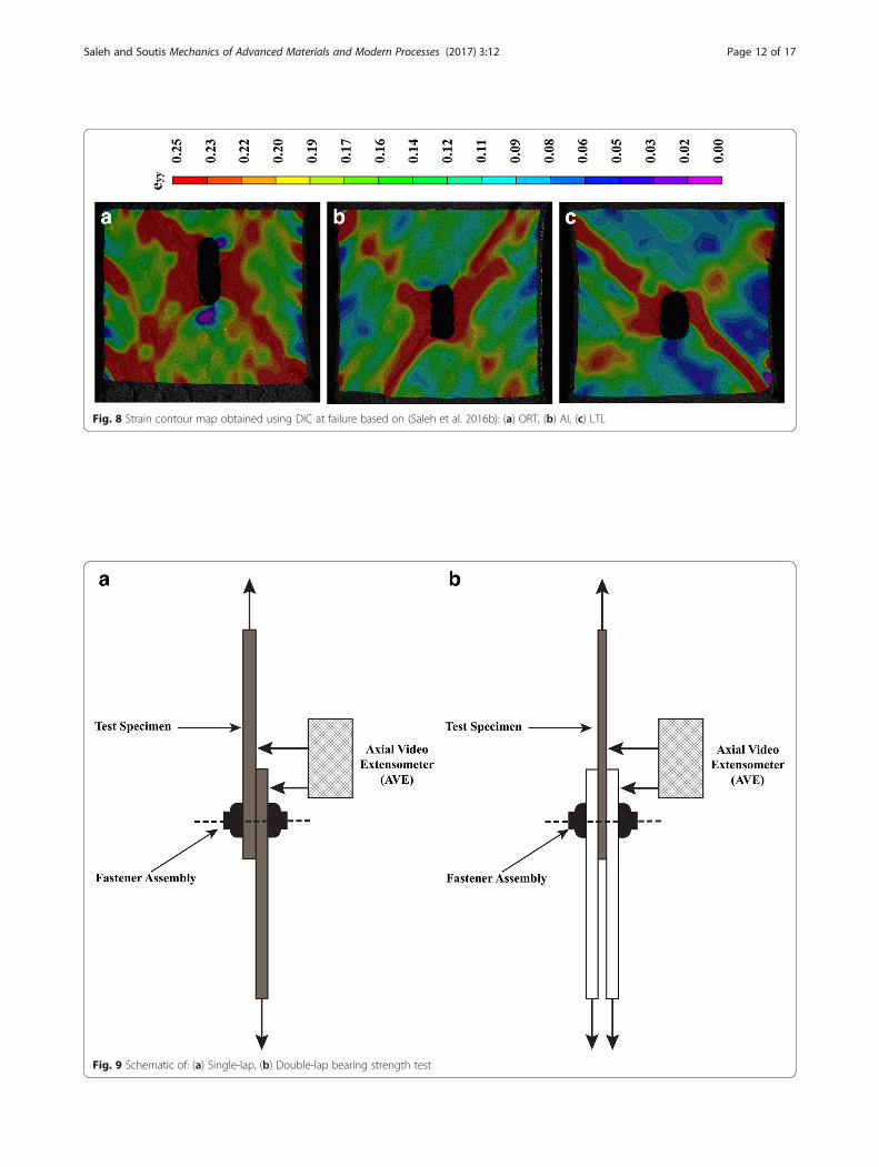
Fig. 8 Strain contour map obtained using DIC at failure based on (Saleh et al. 2016b): (a) ORT, (b) AI, (c) LTL
Fig. 9 Schematic of: (a) Single-lap, (b) Double-lap bearing strength test
Saleh and Soutis Mechanics of Advanced Materials and Modern Processes (2017) 3:12 Page 12 of 17
woven composites as opposed to relatively thinner onesreported by (Warren et al. 2015b; Saleh et al. 2016a). Twotests were conducted namely as the pin-bearing test onhalf-hole and the double-lap pin-bearing test. The de-signed 3D woven fabrics were unbalanced with a higherfibre volume fraction in the warp direction compared tothe weft direction. However, the authors did not specifythe architecture of the 3D woven composite tested in theirstudy. During testing, DIC was used to obtain a full strainmaps and AE was utilised to detect damage initiation andevolution through the accumulated AE energy and theamplitude of the AE events. Authors reported a goodagreement between the bearing strength obtained fromthe half-hole and double-lap tests along the warp and weftdirections, but not in the biased “off-axis” direction. Thiswas attributed to the fact that in the half-hole test the loadcarrying yarns were cut along the cross section for testing.In the case of the double-lap test, the warp-loaded speci-mens demonstrated the highest stiffness but the off-axisloaded specimens had the highest bearing strength, whichsupports the argument proposed earlier by (Saleh et al.2016a) that although off-axis 3D woven composites dem-onstrate less stiffness, they possess significantly betterdamage resistance/tolerance capabilities up to failure.
Finally, the study proposed a damage scenario to explainthe failure of the on-axis loaded specimens which stillneeds to be supported by X-ray CT scans. Kinking of thetows at the loaded edge led to the non-linear behaviourobserved which then developed through the specimen’sthickness forming a network of kink bands, transversecracks and tows debonding. Once the load-carrying yarnsfailed by kinking, it led to the bearing failure observed.
Discussion & concluding remarksAs the objective of this study was to provide a comprehen-sive review of recent experimental work characterising themechanical properties of 3D woven composites, Table 7classifies most of the papers, to the authors’ knowledge,which investigated the un-notched tensile, compressive, in-plane shear, interlaminar shear and flexural response de-pending on the weaving architecture “ORT, LTL or AI”.Such a summary was mainly designed to highlight theknowledge gap in literature and point out different types oftesting required to fully characterise such material systemsahead of relying on them in real life applications. It is clearfrom the comparison that ORT architecture has receivedthe most extensive attention specially in characterising thetensile and compressive response. However, less work hasbeen done to characterise the in-plane shear, flexural andinterlaminar shear response of ORT, LTL and AI. In real lifeapplications, it is quite uncommon for a component orstructure to experience only a single state of stress, so it isquite essential to draw more attention to the lateral types oftesting to realistically characterise 3D woven composites inwhich multiaxial loading conditions are expected.Similarly, Table 8 attempts to summarise the notch
sensitivity characterisation of 3D woven composites as
Fig. 10 Double-lap bearing stress-strain curve (Saleh et al. 2016b): (a) Up to 50%, (b) Up to failure
Table 6 Summary of the bearing strength test results based on(Saleh et al. 2016b)
Textilearchitecture
Bearingstiffness (GPa)
Offset bearingstrength (MPa)
Ultimate bearingstrength (MPa)
ORT 3.48 ± 0.02 429.63 ± 57.53 658.67 ± 27.62
AI 5.26 ± 0.09 456.90 ± 38.33 683.33 ± 9.39
LTL 5.32 ± 0.23 466.97 ± 33.06 677.33 ± 22.95
Saleh and Soutis Mechanics of Advanced Materials and Modern Processes (2017) 3:12 Page 13 of 17

well as the impact response discussed in the literature.One of the major challenges facing the expansion ofusing composite materials in application is the notch ef-fect. However, it is clear from the comparison that thereis very little work focused on understanding the notchedbehaviour of 3D woven composites either loaded alongthe fibre direction “warp/weft” or along a biased “off-axis” direction. On the other hand, a fair amount ofwork has been performed to characterise the impact
behaviour of 3D woven composites that outperforms theimpact performance of unidirectional pre-preg based or2D woven laminates. The potential of using non-destructive testing (NDT) techniques for damage
Table 7 Summary of the available literature for the un-notched mechanical characterisation of 3D woven composites
Tension Compression In-plane Shear/ Off-axisTension
Flexural ILSS
ORT (Cox et al. 1994; Calluset al. 1999; Leong et al.2000; Wang 2006; Quinnet al. 2008; Lomov et al.2009, 2011b; Tong et al.,2009b; Mouritz and Cox2010; Bogdanovich et al.2013; Visrolia and Meo2013; Muñoz et al. 2014;Nasution et al. 2014;Green et al. 2014; Beheraand Dash 2015; Warrenet al. 2015a; Dai et al.2015a; Saleh et al. 2016c;Castaneda et al. 2016;Labanieh et al. 2017)
(Cox et al. 1994; Mouritzet al. 1999a; Wang 2006;Tong and Mouritz MB2009b; Lomov et al.2009; Mouritz and Cox2010; Visrolia and Meo2013; Behera and Dash2015; Warren et al.2015a; Dai et al. 2015a;Turner et al. 2016)
(Lomov et al. 2009;Bogdanovich et al. 2013;Visrolia and Meo 2013;Warren et al. 2015a;Saleh et al. 2016c;Labanieh et al. 2017)
(Chou et al. 1992; Coxet al. 1994; Wang 2006;Tong et al., 2009b;Nasution et al. 2014;Behera and Dash 2015;Dai et al. 2015a)
(Wang 2006; Tong et al.,2009b; Mouritz and Cox2010; Walter et al. 2010;Labanieh et al. 2017)
AI (Cox et al. 1994, 1996;Pochiraju 1999; Tonget al., 2009b; Mouritzand Cox 2010; Gerlachet al. 2012; Mubeen2014; Behera and Dash2015; Yu et al. 2015a;Dai et al. 2015a; Salehet al. 2016c)
(Cox et al., 1994;Pochiraju 1999; Tonget al., 2009b; Mouritzand Cox 2010; Beheraand Dash 2015; Dai et al.2015a)
(Pochiraju 1999;Buchanan et al. 2012;Saleh et al.2016c)
(Cox et al. 1994; Tonget al., 2009b; Mouritzand Cox 2010; Yanget al. 2014; Behera andDash 2015; Dai et al.2015a; Umer et al. 2016)
(Tong et al., 2009b;Mouritz and Cox 2010;Walter et al. 2010)
LTL (Cox et al. 1994, 1996;Callus et al. 1999;Pochiraju 1999; Stig andHallström 2009; Mubeen2014; Warren et al.2015a; Yu et al. 2015a;Saleh et al. 2016c)
(Cox et al., 1994; Mouritzet al. 1999b; Stig andHallström 2009; Mahadikand Hallett 2011; Daiet al. 2015a; Warrenet al. 2015a)
(Pochiraju 1999; Warrenet al. 2015a; Saleh et al.2016c)
(Cox et al. 1994; Umeret al. 2016)
(Stig and Hallström2009)
Table 8 Summary of the available literature for the notched andimpact mechanical characterisation of 3D woven composites
Open-hole BearingStrength
Impact/Indentation
ORT (Dai et al.2015b; Salehet al. 2016b)
(Warren et al.2015b; Salehet al. 2016b)
(Baucom and Zikry 2003; Jiet al. 2007; Luo et al. 2007;Hao et al. 2008; Potluri et al.2012; Seltzer et al. 2013;Umer et al. 2016)
AI (Mubeen 2014;Dai et al.2015b; Salehet al. 2016b)
(Saleh et al.2016b)
(Gerlach et al. 2012; Potluriet al. 2012; Mubeen 2014;Behera and Dash 2015;Umer et al. 2016; Wanget al. 2017)
LTL (Mubeen 2014;Saleh et al.2016b)
(Saleh et al.2016b)
(Potluri et al. 2012; Mubeen2014; Umer et al. 2016;Elias et al. 2017)
Table 9 Summary of the available literature of the NDTtechniques used for 3D woven composites
DIC AE X-ray CT
ORT (Ivanov et al. 2009;Lomov et al. 2009;Bogdanovich et al.2013; Dai et al.2015a, 2015b;Warren et al. 2015a;Castaneda et al.2016; Saleh et al.2016a, c; Labaniehet al. 2017)
(Ivanov et al. 2009;Lomov et al. 2009,2011a;Bogdanovich et al.2013; Li et al. 2014;Castaneda et al.2016)
(Ivanov et al. 2009;Lomov et al. 2009;Bogdanovich et al.2013; Seltzer et al.2013; Muñoz et al.2014; Castanedaet al. 2016; Salehet al. 2016b, c;Umer et al. 2016)
AI (Mubeen 2014; Daiet al. 2015a, 2015b;Saleh et al. 2016c)
(Gresil et al. 2016) (Gerlach et al.2012; Yu et al.2015b, Yu et al.2016b, Saleh et al.2016b, 2016c;Umer et al. 2016)
LTL (Mubeen 2014;Warren et al. 2015a;Saleh et al. 2016c)
Not available (Yu et al. 2015b,Saleh et al. 2016a,Saleh et al. 2016b,c; Umer et al. 2016)
Saleh and Soutis Mechanics of Advanced Materials and Modern Processes (2017) 3:12 Page 14 of 17
detection in 3D woven composites is summarised inTable 9. Several researchers utilised DIC, X-ray CT andAE techniques to characterise damage in ORT architec-ture with less focus on AI and almost minimal attentionto LTL. This suggests a room for improvement in estab-lishing such techniques specially AE as a valuable NDTtechnique for damage initiation and evolution detectionfor 3D woven composites.As a general remark from the reviewed studies, having a
through-thickness z-binder (ORT and AI) can suppressdelamination and delay final failure. However, in the caseof LTL architecture, delamination progression betweenlayers is guided by the z-binding yarns, which leads tofinal failure. The same effect is observed in the cases ofthe un-notched, notched and bearing response of 3Dwoven composites. This suggests that optimisation of 3Dwoven composites design should consider the z-binderarchitecture depending on the application and avoid theLTL binding approach. Then, the second optimisationparameter is the z-binder frequency going from top tobottom “unit-cell size”. For applications in which highstrain to failure and higher energy absorption required,smaller weaving architecture unit-cell with higher z-binder density should be adopted such as the ORT archi-tecture. In conclusion, 3D woven composites have proventhat not only they have enhanced out-of-plane properties,but also better damage resistance/tolerance and enhancedin-plane properties when compared to their counterpartsof unidirectional pre-preg based or 2D woven laminates.
Abbreviations2D: Two-dimensional; 3D: Three-dimensional; AE: Acoustic emission; AI: Angleinterlock; CFRP: Carbon fibre reinforced polymers; CT: Computedtomography; DIC: Digital image correlation; FEM: Finite element modeling;ILSS: Interlaminar shear strength; LTL: Layer-to-layer; NDT: Non-destructivetesting; ORT: Orthogonal; RFI: Resin film infusion; TT: Through-thicknessIntroduction
AcknowledgmentsNot applicable.
FundingNot applicable.
Availability of data and materialsThe data and materials supporting this review are available online as per thecited journal publications and conference proceedings.
Authors’ contributionsMNS: combined the different studies available in the literature and wrote themanuscript. CS: helped in reviewing and editing it. Both authors read andapproved the final manuscript.
Competing interestsThe authors declare that they have no competing interest.
Consent for publicationNot applicable.
Ethics approval and consent to participateNot applicable.
EndnotesNot applicable.
Publisher’s NoteSpringer Nature remains neutral with regard to jurisdictional claims inpublished maps and institutional affiliations.
Author details1Advanced Manufacturing Research Centre with Boeing, University ofSheffield, S60 5TZ, Rotherham, UK. 2Aerospace Research Institute, Universityof Manchester, M1 3NJ, Manchester, UK.
Received: 27 April 2017 Accepted: 8 June 2017
ReferencesAnsar M, Xinwei W, Chouwei Z (2011) Modeling strategies of 3D woven
composites: a review. Compos Struct 93:1947–1963. doi:10.1016/j.compstruct.2011.03.010
Atas A (2012) Strength prediction of mechanical joints in composite laminatesbased on subcritical damage Modelling.
Ataş A, Soutis C (2013) Subcritical damage mechanisms of bolted joints in CFRPcomposite laminates. Compos Part B Eng 54:20–27. doi:10.1016/j.compositesb.2013.04.071
Ataş A, Soutis C (2014) Strength prediction of bolted joints in CFRP compositelaminates using cohesive zone elements. Compos Part B Eng 58:25–34.doi:10.1016/j.compositesb.2013.10.017
Awerbuch J, Madhukar MS (1985) Notched strength of composite Laminates :predictions and experiments & mdash - a review. J Reinf Plast Compos Reinf4:3–159. doi:10.1177/073168448500400102
Baucom JN, Zikry MA (2003) Evolution of failure mechanisms in 2D and 3Dwoven compositesystems under quasi-static perforation. J Compos Mater37:1651–1674. doi:10.1177/002199803035178
Bayraktar H, Ehrlich D, Goering J, et al. (2015) 3D woven composites for energyabsorbing. In: 20th international conference on composite materials.Copenhagen, pp 19–24
Behera BK, Dash BP (2015) Mechanical behavior of 3D woven composites. MaterDes 67:261–271. doi:10.1016/j.matdes.2014.11.020
Bogdanovich AE, Karahan M, Lomov SV, Verpoest I (2013) Quasi-static tensilebehavior and damage of carbon/epoxy composite reinforced with 3D non-crimp orthogonal woven fabric. Mech Mater 62:14–31. doi:10.1016/j.mechmat.2013.03.005
Buchanan S, Archer E, Townsend D et al (2012) Determination of in-plane shearmodulus of 3D woven composites with large repeat unit cells. Plast RubberCompos 41:194–198. doi:10.1179/1743289811y.0000000060
Callus PJ (2007) The effects of hole-size and environment on the mechanicalbehaviour of a quasi-isotropic AS4/3501-6 laminate in tension. CompressionBending Air Veh Div Def Sci Technol Organ:1–82
Callus PJ, Mouritz AP, Bannister MK, Leong KH (1999) Tensile properties andfailure mechanisms of 3D woven GRP composites. Compos Part A Appl SciManuf 30:1277–1287. doi:10.1016/S1359-835X(99)00033-0
Castaneda N, Wisner B, Cuadra J et al (2016) Investigation of the Z-binder role inprogressive damage of 3D woven composites. Compos Part A Appl SciManuf 98:76–89. doi:10.1016/j.compositesa.2016.11.022
Chou S, Chen HC, Chen HE (1992) Effect of weave structure on mechanical fracturebehavior of three-dimensional carbon fiber fabric reinforced epoxy resincomposites. Compos Sci Technol 45:23–35. doi:10.1016/0266-3538(92)90119-N
Cox B, Dadkhah M, Morris W, Flintoff J (1994) Failure mechanisms of 3D wovencomposites in tension, compression, and bending. Acta Metall Mater.doi:10.1016/0956-7151(94)90174-0
Cox BN, Dadkhah MS, Morris WL (1996) On the tensile failure of 3D wovencomposites. Compos Part A Appl Sci Manuf 27:447–458. doi:10.1016/1359-835X(95)00053-5
Dai S, Cunningham PR, Marshall S, Silva C (2015a) Influence of fibre architecture onthe tensile, compressive and flexural behaviour of 3D woven composites.Compos Part A Appl Sci Manuf 69:195–207. doi:10.1016/j.compositesa.2014.11.012
Dai S, Cunningham PR, Marshall S, Silva C (2015b) Open hole quasi-static andfatigue characterisation of 3D woven composites. Compos Struct 131:765–774. doi:10.1016/j.compstruct.2015.06.032
Elias A, Laurin F, Kaminski M, Gornet L (2017) Experimental and numericalinvestigations of low energy/velocity impact damage generated in 3D
Saleh and Soutis Mechanics of Advanced Materials and Modern Processes (2017) 3:12 Page 15 of 17

woven composite with polymer matrix. Compos Struct 159:228–239. doi:10.1016/j.compstruct.2016.09.077
Gerlach R, Siviour CR, Wiegand J, Petrinic N (2012) In-plane and through-thickness properties, failure modes, damage and delamination in 3D wovencarbon fibre composites subjected to impact loading. Compos Sci Technol72:397–411. doi:10.1016/j.compscitech.2011.11.032
Green SD, Matveev MY, Long AC et al (2014) Mechanical modelling of 3D wovencomposites considering realistic unit cell geometry. Compos Struct 118:284–293. doi:10.1016/j.compstruct.2014.07.005
Gresil M, Saleh MN, Soutis C (2016) Transverse Crack Detection in 3D AngleInterlock Glass Fibre Composites Using Acoustic Emission. Materials (Basel).doi:10.3390/ma9080699
Hao A, Sun B, Qiu Y, Gu B (2008) Dynamic properties of 3-D orthogonal wovencomposite T-beam under transverse impact. Compos Part A Appl Sci Manuf39:1073–1082. doi:10.1016/j.compositesa.2008.04.012
Hemrick JG, Lara-Curzio E, Loveland ER et al (2011) Woven graphite fiberstructures for use in ultra-light weight heat exchangers. Carbon N Y 49:4820–4829. doi:10.1016/j.carbon.2011.06.094
Ivanov DS, Lomov SV, Bogdanovich AE et al (2009) A comparative study oftensile properties of non-crimp 3D orthogonal weave and multi-layer plainweave E-glass composites. Part 2: comprehensive experimental results.Compos Part A Appl Sci Manuf 40:1144–1157. doi:10.1016/j.compositesa.2009.04.032
Jewell J, Kennedy R, Menard A (2011) Full-scale LEAP Fan Blade-Out Rig TestYields Outstanding Results; Advanced LEAP Fan Endurance Test Complete.In: CFM Power Flight.
Ji C, Sun B, Qiu Y, Gu B (2007) Impact damage of 3D orthogonal wovencomposite circular plates. Appl Compos Mater 14:343–362. doi:10.1007/s10443-008-9050-x
Kelly G, Hallström S (2004) Bearing strength of carbon fibre/epoxy laminates:effects of bolt-hole clearance. Compos Part B Eng 35:331–343. doi:10.1016/j.compositesb.2003.11.001
Khashaba UA, Sebaey TA, Alnefaie KA (2013) Failure and reliability analysis ofpinned-joints composite laminates: effects of stacking sequences. ComposPart B Eng 45:1694–1703. doi:10.1016/j.compositesb.2012.09.066
Labanieh AR, Liu Y, Vasiukov D et al (2017) Influence of off-axis in-plane yarns onthe mechanical properties of 3D composites. Compos Part A Appl Sci Manuf98:45–57. doi:10.1016/j.compositesa.2017.03.009
Leong KH, Lee B, Herszberg I, Bannister MK (2000) The effect of binder path onthe tensile properties and failure of multilayer woven CFRP composites.Compos Sci Technol 60:149–156. doi:10.1016/S0266-3538(99)00108-6
Li L, Lomov SV, Yan X, Carvelli V (2014) Cluster analysis of acoustic emissionsignals for 2D and 3D woven glass/epoxy composites. Compos Struct116:286–299. doi:10.1016/j.compstruct.2014.05.023
Lomov SV, Bogdanovich AE, Ivanov DS et al (2009) A comparative study oftensile properties of non-crimp 3D orthogonal weave and multi-layer plainweave E-glass composites. Part 1: materials, methods and principal results.Compos Part A Appl Sci Manuf 40:1134–1143. doi:10.1016/j.compositesa.2009.04.032
Lomov SV, Bogdanovich a E, Karahan M et al (2011) Mechanical behaviour ofnon-crimp 3D woven carbon/epoxy composite under in-plane tensileloading. ICCM 18:1–5
Luo Y, Lv L, Sun B et al (2007) Transverse impact behavior and energy absorptionof three-dimensional orthogonal hybrid woven composites. Compos Struct81:202–209. doi:10.1016/j.compstruct.2006.08.011
Mahadik Y, Hallett SR (2011) Effect of fabric compaction and yarn waviness on3D woven composite compressive properties. Compos Part A Appl SciManuf 42:1592–1600. doi:10.1016/j.compositesa.2011.07.006
Mcclain M, Senior R, Organic TE, Composites M (2012) Overview of recentdevelopments in 3D structures. Albany Eng Compos:1–12
Mittelstedt C, Becker W (2004) Interlaminar stress concentrations in layeredstructures: part I - a selective literature survey on the free-edge effect since1967. J Compos Mater 38:1037–1062. doi:10.1177/0021998304040566
Mittelstedt C, Becker W (2007) Free-edge effects in composite laminates. ApplMech Rev 60:217. doi:10.1115/1.2777169
Mohamed MH, Wetzel KK (2006) 3D woven carbon/glass hybrid spar cap forwind turbine rotor blade. J Sol Energy Eng 128:562–573. doi:10.1115/1.2349543
Mounien R, Fagiano C, Paulmier P et al (2016) Experimental characterization ofthe bearing behavior of 3D woven composites. Compos Part B Eng:1–8.doi:10.1016/j.compositesb.2016.10.077
Mouritz AP, Cox BN (2010) A mechanistic interpretation of the comparative in-planemechanical properties of 3D woven, stitched and pinned composites. ComposPart A Appl Sci Manuf 41:709–728. doi:10.1016/j.compositesa.2010.02.001
Mouritz AP, Bannister MK, Falzon PJ, Leong KH (1999a) Review of applications foradvanced threedimensional fibre textile composites. Compos Part A Appl SciManuf 30:1445–1461. doi:10.1016/S1359-835X(99)00034-2
Mubeen A (2014) Damage Tolerance of 3D Woven Composites with WeftBinders. The University of Manchester
Muñoz R, Martínez V, Sket F et al (2014) Mechanical behavior and failuremicromechanisms of hybrid 3D woven composites in tension. Compos PartA Appl Sci Manuf 59:93–104. doi:10.1016/j.compositesa.2014.01.003
Naik NK, Shembekar PS, Verma MK (1990) On the influence of stacking sequenceon notch sensitivity of fabric laminates. J Compos Mater 24:838–852. doi:10.1177/002199839002400804
Nasution MRE, Watanabe N, Kondo A, Yudhanto A (2014) Thermomechanicalproperties and stress analysis of 3-D textile composites by asymptoticexpansion homogenization method. Compos Part B Eng 60:378–391.doi:10.1016/j.compositesb.2013.12.038
Öndürücü A, Esendemir Ü, Tunay RF (2012) Progressive failure analysis of glass-epoxy laminated composite pinned-joints. Mater Des 36:617–625. doi:10.1016/j.matdes.2011.11.031
Pisano AA, Fuschi P (2011) Mechanically fastened joints in composite laminates:evaluation of load bearing capacity. Compos Part B Eng 42:949–961.doi:10.1016/j.compositesb.2010.12.016
Pochiraju K (1999) Three-dimensionally woven and braided composites. II: anexperimental characterization. Polym Compos 20:733–747
Potluri P, Hogg P, Arshad M et al (2012) Influence of fibre architecture on impactdamage tolerance in 3D woven composites. Appl Compos Mater 19:799–812. doi:10.1007/s10443-012-9256-9
Quinn JP, McIlhagger AT, McIlhagger R (2008) Examination of the failure of 3Dwoven composites. Compos Part A Appl Sci Manuf 39:273–283. doi:10.1016/j.compositesa.2007.10.012
Redman C, Bayraktar H, Mcclain M (2014) Curved beam test Behavior of 3Dwoven composites.
Rudov-Clark S (2007) Experimental investigation of the tensile properties andfailure mechanisms of three-dimensional woven composites.
Saleh MN, Wang Y, Yudhanto A et al (2016a) Investigating the potential of usingoff-Axis 3D woven composites in composite joints’ applications. ApplCompos Mater 24:377–396. doi:10.1007/s10443-016-9529-9
Saleh MN, Yudhanto A, Potluri P et al (2016b) Characterising the loading directionsensitivity of 3D woven composites: effect of z-binder architecture. Compos PartA Appl Sci Manuf 90:577–588. doi:10.1016/j.compositesa.2016.08.028
Seltzer R, González C, Muñoz R et al (2013) X-ray microtomography analysis ofthe damage micromechanisms in 3D woven composites under low-velocityimpact. Compos Part A Appl Sci Manuf 45:49–60. doi:10.1016/j.compositesa.2012.09.017
Sharp K, Bogdanovich A, Boyle R et al (2013) Wind blade joints based on non-crimp 3D orthogonal woven pi shaped preforms. Compos Part A Appl SciManuf 49:9–17. doi:10.1016/j.compositesa.2013.01.012
Shembekar PS, Naik NK (1992) Notched strength of fabric laminates. II: effect of stackingsequence. Compos Sci Technol 44:13–20. doi:10.1016/0266-3538(92)90021-T
Stig F (2012) 3D–woven Reinforcement in Composites. KTH SwedenStig F, Hallström S (2009) Assessment of the mechanical properties of a new 3D
woven fibre composite material. Compos Sci Technol 69:1686–1692.doi:10.1016/j.compscitech.2008.04.047
Stig F, Hallström S (2013) Influence of crimp on 3D-woven fibre reinforcedcomposites. Compos Struct 95:114–122. doi:10.1016/j.compstruct.2012.07.022
Sun CT, Chu GD (1991) Reducing free edge effect on laminate strength by edgemodification. J Compos Mater 25:142–161. doi:10.1016/0010-4361(91)90599-C
Tan P, Tong L, Steven GP, Ishikawa T (2000) Behavior of 3D orthogonal wovenCFRP composites. Part I. Experimental investigation. Compos Part A Appl SciManuf 31:259–271. doi:10.1016/S1359-835X(99)00070-6
Thoppul SD, Finegan J, Gibson RF (2009) Mechanics of mechanically fastenedjoints in polymer-matrix composite structures - a review. Compos SciTechnol 69:301–329. doi:10.1016/j.compscitech.2008.09.037
Tong L, Mouritz MB AP (2009b) Chapter 5 3D Woven Composites. In: 3D FibreReinforced Polymer Composites
Tong L, Mouritz AP, Bannister M (2009a) Chapter 2 Manufacture of 3D FibrePreforms. In: 3D Fibre Reinforced Polymer Composites.
Tong L, Mouritz AP, Bannister M (2009b) Chapter 5 3D Woven Composites. In: 3DFibre Reinforced Polymer Composites.
Saleh and Soutis Mechanics of Advanced Materials and Modern Processes (2017) 3:12 Page 16 of 17

Tsai KH, Chiu CH, Wu TH (2000) Fatigue behavior of 3D multi-layer angleinterlock woven composite plates. Compos Sci Technol 60:241–248.doi:10.1016/S0266-3538(99)00120-7
Turner P, Liu T, Zeng X (2016) Collapse of 3D orthogonal woven carbon fibrecomposites under inplane tension/compression and out-of-plane bending.Compos Struct 142:286–297. doi:10.1016/j.compstruct.2016.01.100
Umer R, Alhussein H, Zhou J, Cantwell W (2016) The mechanical properties of 3Dwoven composites. J Compos Mater. doi:10.1177/0021998316681187
Visrolia A, Meo M (2013) Multiscale damage modelling of 3D weave compositeby asymptotic homogenisation. Compos Struct 95:105–113. doi:10.1016/j.compstruct.2012.07.018
Walter TR, Subhash G, Sankar BV, Yen CF (2009) Damage modes in 3D glass fiberepoxy woven composites under high rate of impact loading. Compos Part BEng 40:584–589. doi:10.1016/j.compositesb.2009.04.021
Walter TR, Subhash G, Sankar BV, Yen CF (2010) Monotonic and cyclic shortbeam shear response of 3D woven composites. Compos Sci Technol 70:2190–2197. doi:10.1016/j.compscitech.2010.08.022
Wang Y (2006) Effect of fabric structures on the mechanical properties of 3-Dtextile composites. J Ind Text 35:239–256. doi:10.1177/1528083706057595
Wang M, Cao M, Wang H et al (2017) Drop-weight impact behaviors of 3-Dangle interlock woven composites after thermal oxidative aging. ComposStruct 166:239–255. doi:10.1016/j.compstruct.2017.01.046
Warren KC, Lopez-Anido RA, Goering J (2015a) Experimental investigation ofthree-dimensional woven composites. Compos Part A Appl Sci Manuf73:242–259. doi:10.1016/j.compositesa.2015.03.011
Warren KC, Lopez-Anido RA, Goering J (2015b) Behavior of three-dimensionalwoven carbon composites in single-bolt bearing. Compos Struct 127:175–184.doi:10.1016/j.compstruct.2015.03.022
Yang G, Sun B, Gu B (2014) Large-scale finite element analysis of a 3D angle-interlock woven composite undergoing low-cyclic three-point bendingfatigue. J Text Inst 105:275–293. doi:10.1080/00405000.2013.836785
Yu B, Bradley RS, Soutis C et al (2015a) 2D and 3D imaging of fatigue failuremechanisms of 3D woven composites. Compos Part A Appl Sci Manuf77:37–49. doi:10.1016/j.compositesa.2015.06.013
Yu B, Bradley RS, Soutis C et al (2016b) A comparison of different approaches forimaging cracks in composites by X-ray microtomography. Philos Trans AMath Phys Eng Sci 374:20160037. doi:10.1098/rsta.2016.0037
Yudhanto A, Iwahori Y, Watanabe N, Hoshi H (2012a) Open hole fatiguecharacteristics and damage growth of stitched plain weave carbon/epoxylaminates. Int J Fatigue 43:12–22. doi:10.1016/j.ijfatigue.2012.02.002
Yudhanto A, Watanabe N, Iwahori Y, Hoshi H (2012b) The effects of stitchorientation on the tensile and open hole tension properties of carbon/epoxyplain weave laminates. Mater Des 35:563–571. doi:10.1016/j.matdes.2011.09.013
Saleh and Soutis Mechanics of Advanced Materials and Modern Processes (2017) 3:12 Page 17 of 17