real-time parametric surface modeling for free-form
TRANSCRIPT

RealReal--time Parametric Surface Modeling time Parametric Surface Modeling for Freefor Free--form Conceptual Designform Conceptual Design
Presented by: Lan WuPresented by: Lan Wu
Supervisor: Dr. Ali AkgunduzSupervisor: Dr. Ali AkgunduzDepartment of Mechanical and Industrial Department of Mechanical and Industrial
Concordia UniversityConcordia UniversityAugust 2008August 2008

MotivationMotivationConceptual design is the initial stage of the product Conceptual design is the initial stage of the product design cycledesign cycleThe aesthetic features are added into the design by the The aesthetic features are added into the design by the means of the creative inspiration and imaginationmeans of the creative inspiration and imaginationDesign is a collaborative effort, requires several Design is a collaborative effort, requires several iterationiterationDetailed design is realized in CAD systemsDetailed design is realized in CAD systemsHence, there is a need for systems whereHence, there is a need for systems where–– Designers can freely convey their thoughts and imaginations intoDesigners can freely convey their thoughts and imaginations into
geometric shapesgeometric shapes–– Without any constraint: without dealing with the technical detaiWithout any constraint: without dealing with the technical detailsls–– Directly into 3D space so:Directly into 3D space so:
Sketches are better perceived by the third partiesSketches are better perceived by the third partiesEasier to convert them in to CAD formatsEasier to convert them in to CAD formatsEasier to perform engineering analysisEasier to perform engineering analysis

ObjectivesObjectives
Introduce a freeIntroduce a free--form conceptual design toolkit form conceptual design toolkit Enables designers to display their ideas Enables designers to display their ideas instantaneously and inspirationallyinstantaneously and inspirationallyDirectly in 3D spaceDirectly in 3D spaceUsing immersive or nonUsing immersive or non--immersive VR systemsimmersive VR systems

Contributions of the ThesisFree-form sketching system– Inputs are received from the user’s hand– Data is converted into parametric surfaces– Real-time modification is enabled
Connecting surface patches while the continuity is ensured
Adding a thickness to the arbitraryAdding a thickness to the arbitrarydesigned objectsdesigned objects
Surface trimming is possible

Literature Review
Freeform design methods– Wesche, 2001– Schkolne, 2006– Akgunduz, 2005
Literature on continuity and surface thickness– Hongwei Lin and Hujun Bao, 2007– Jana Pilnikova et al., 1998– Barian A. Barsky, 1990

Methodology
RealReal--time parametric surface modeling time parametric surface modeling (NURB(NURB))
Data sourcesData sourcesIndependent motion controlIndependent motion controlData generation and processData generation and processLeastLeast--square method to obtain the square method to obtain the NURB surface modeling.NURB surface modeling.

Data sourcesData sourcesNumbers 4, 5, 6, 7 are the index of the green color points whichNumbers 4, 5, 6, 7 are the index of the green color points which are are adhered on the joints of the index finger of the right handadhered on the joints of the index finger of the right handWe use these points as the shape generation sourceWe use these points as the shape generation source

Independent motion control Independent motion control
In our sketching system, the user motion (userIn our sketching system, the user motion (user’’s hand) s hand) virtual space and the designed object are subject to virtual space and the designed object are subject to independent motionindependent motion
The relative motion among the virtual objects are The relative motion among the virtual objects are sustained by applying the corresponding reverse matrix sustained by applying the corresponding reverse matrix of objects motion to separate the its motion relation of objects motion to separate the its motion relation between thembetween them

Data generation methods and Data generation methods and processprocess
singlesingle--pointpoint--generation and processgeneration and processmultimulti--pointpoint--generation and processgeneration and process
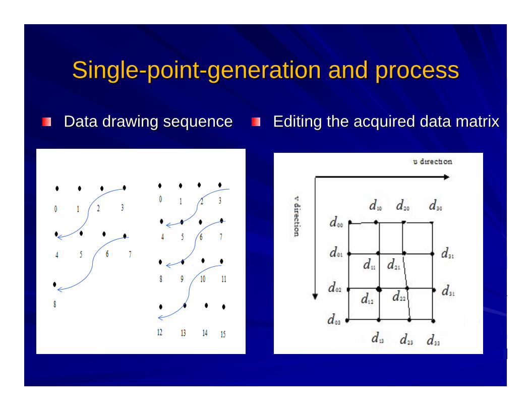
SingleSingle--pointpoint--generation and processgeneration and process
Data drawing sequenceData drawing sequence Editing the acquired data matrixEditing the acquired data matrix
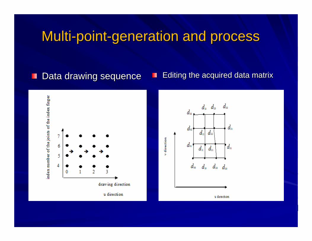
MultiMulti--pointpoint--generation and processgeneration and process
Editing the acquired data matrixEditing the acquired data matrixData drawing sequenceData drawing sequence

From virtual hand to Parametric Surfaces
Input Sources
Single-point-generation
Multi-point generation
Finding Control Points
Generating NURB Surface
Patches
From Surface Patches to Complete Design
Single NURB surface is not suitable to generate all complex geometriesFinal products usually require number of surface patches to be connected to each otherUsing surface patches and stitching them together – Flexible– Surface patches better fit to the desired geometry– Enables generating complex geometries– Local modifications possible– Assembly/disassembly is possible– Local modifications eliminate redundant calculations

C1 smooth connection C1 smooth connection
1.1. Construct fillet surface to achieve C1 Construct fillet surface to achieve C1 smooth connection between two stitched smooth connection between two stitched NURB patches.NURB patches.
2.2. BuildBuild--up NURB patches to fill in the holesup NURB patches to fill in the holesto achieve the C1 smooth transition along to achieve the C1 smooth transition along their common boundaries as more than their common boundaries as more than two patches are stitched together two patches are stitched together surrounding at their common joint point.surrounding at their common joint point.

Construct fillet surfaceConstruct fillet surface
Method used to construct the fillet surfaceMethod used to construct the fillet surface

Using the proposed Stitching techniqueUsing the proposed Stitching techniquewe obtain fillet NURB surfaces which hold we obtain fillet NURB surfaces which hold
the following properties:the following properties:–– If the full multiplicity properties can be held by the end If the full multiplicity properties can be held by the end
knots, the control polygons of the parametric surface knots, the control polygons of the parametric surface boundary curves will be the boundary polygons of the boundary curves will be the boundary polygons of the control polygon meshcontrol polygon mesh
–– When the When the order order k k of the Bof the B--splinespline is equal to is equal to 22, the , the parametric mesh will be its control polygon mesh itselfparametric mesh will be its control polygon mesh itself
–– The boundary polygons of the parametric mesh pass The boundary polygons of the parametric mesh pass through the four corner points of the control polygon mesh through the four corner points of the control polygon mesh and tangent to the boundary polygon of control polygon at and tangent to the boundary polygon of control polygon at these four points if the end knots have full multiplicity.these four points if the end knots have full multiplicity.

These three properties guarantee to maintain These three properties guarantee to maintain the C1 continuity the C1 continuity forfor the filletthe fillet NURB surface NURB surface duedueto:to:–– Boundaries being overlapped along the Boundaries being overlapped along the vv direction;direction;–– At the four end points of the control polygon, the boundary At the four end points of the control polygon, the boundary
conditions for C1 continuity being heldconditions for C1 continuity being held

Fill in the holesFill in the holes

Case 1: Two stitched patchesCase 1: Two stitched patches

Case 2:Four stitched NURB Case 2:Four stitched NURB patches.patches.
Four stitched patches before C1 and after C1connection.Four stitched patches before C1 and after C1connection.

The construction of the NURB patch used to fill in the hole between four stitched patches with C1 continuity smooth transition

Case 3:Three stitched NURB Case 3:Three stitched NURB patches.patches.
Three stitched patches before C1 and after C1connection.Three stitched patches before C1 and after C1connection.


Case 4: Five stitched NURB Case 4: Five stitched NURB patchespatches

Adding the thickness to the Adding the thickness to the arbitrary designed objectsarbitrary designed objects
MethodologyMethodology–– Calculate the geometric center for the designed Calculate the geometric center for the designed
objectsobjects–– Pull the geometric center of the designed objects to Pull the geometric center of the designed objects to
the original point set up in our systemthe original point set up in our system–– Given amplification coefficient for x, y and z directionsGiven amplification coefficient for x, y and z directions–– Connect the corresponding points on two imagesConnect the corresponding points on two images
0
1
n
ii
i
SMG C
n==
+
∑ ,
,
,
0 00 00 0
i x
i y
i z
GCT GC
GC
⎡ ⎤⎢ ⎥⎢ ⎥⎢ ⎥⎣ ⎦
−= −
−
0 00 00 0
x
y
z
tS t
t
⎡ ⎤⎢ ⎥⎢ ⎥⎢ ⎥⎣ ⎦
=

Outstanding Issues
Problem is corrected using a scaling factor S
The issues such as above may not be resolved easily by employing a scaling factor to the geometry.
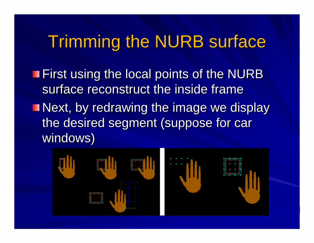
Trimming the NURB surfaceTrimming the NURB surface
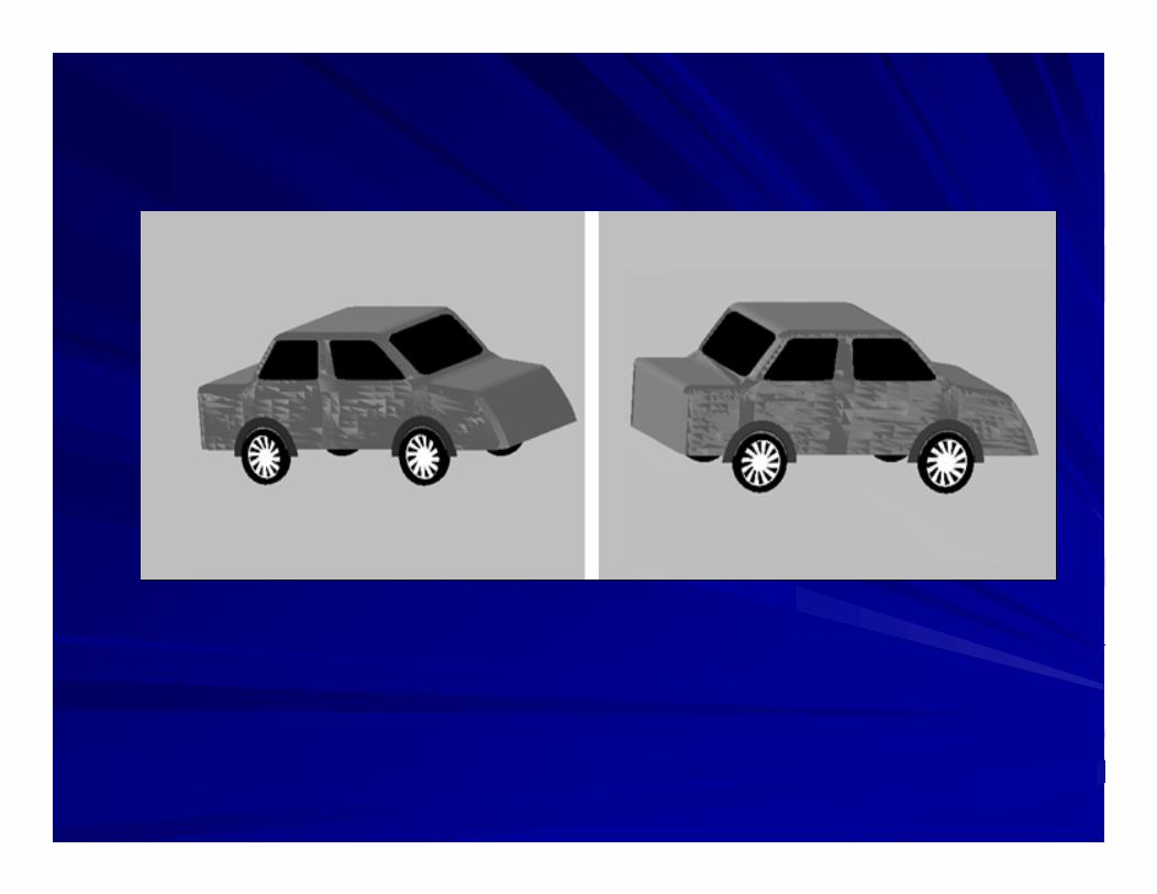
FirstFirst using the local points of the NURB using the local points of the NURB surface reconstruct the inside frame surface reconstruct the inside frame Next, by redrawing the image we display Next, by redrawing the image we display the desired segment (suppose for car the desired segment (suppose for car windows)windows)

The second trimming approach we employed isThe second trimming approach we employed is–– First, take out the NURBS surface local points to First, take out the NURBS surface local points to
reconstruct the outline curves reconstruct the outline curves –– Next, by using the background color (suppose dark Next, by using the background color (suppose dark
color) with a certain thickness to hide the undesired color) with a certain thickness to hide the undesired images around the shape outline curves, we can images around the shape outline curves, we can display the desired images. display the desired images.
This approach enables us to generate highly This approach enables us to generate highly complex geometries using parametric equations.complex geometries using parametric equations.Since the main motivation is Since the main motivation is ““Conceptual Conceptual DesignDesign””, not removing the actual data is not , not removing the actual data is not giving any drawbackgiving any drawback
Trimming the NURB surfaceTrimming the NURB surface

Trimming the NURB surfaceTrimming the NURB surface

Summary of the Proposed MethodSummary of the Proposed Method
By now, we introduce our methods used to By now, we introduce our methods used to perform freeperform free--form conceptual design in form conceptual design in four stepsfour steps–– The generation of the NURB patchThe generation of the NURB patch–– C1 smooth connectionC1 smooth connection–– Adding the thicknessAdding the thickness–– Trimming the NURB surfaceTrimming the NURB surface
Next, we use four examples to show the Next, we use four examples to show the results of our methodsresults of our methods

Example 1. Car modelingExample 1. Car modeling

Example 2: Table lampExample 2: Table lamp

Example 3: MicrowaveExample 3: Microwave

Example 4: A chair and tableExample 4: A chair and table

Example 5: A chair imageExample 5: A chair image
A chair image wire model and drawing A chair image wire model and drawing sequence. sequence.

Example 5: A chair image Example 5: A chair image

Contributions and Future Works

Questions ?Questions ?

Thank You !Thank You !