re-fueled - calvin.edu · the fuel making process is low cost and simple to implement with the...
TRANSCRIPT
2009
Jeff De Jong, Bethany Kortman, Jeena Velzen
Calvin College Engineering
Re-Fueled
i
Executive Summary
The project goal was to design a simple low cost process to create fuel from waste material,
bringing justice to the people of Malawi by increasing the availability of fuel and reducing the
effects of deforestation. The fuel making process is low cost and simple to implement with the
intent of having wide adoption: providing fuel, reducing waste, and creating jobs in developing
nations.
The intended power source for this project was human work which incorporated design elements
such as gears and chains which can be scavenged from bicycles or other available materials in
the area, aiding in the cultural appropriateness of the design. By creating a people powered
process, the design will provide jobs for individuals within the context of the project with the
possibility of selling the fuel product for a profit.
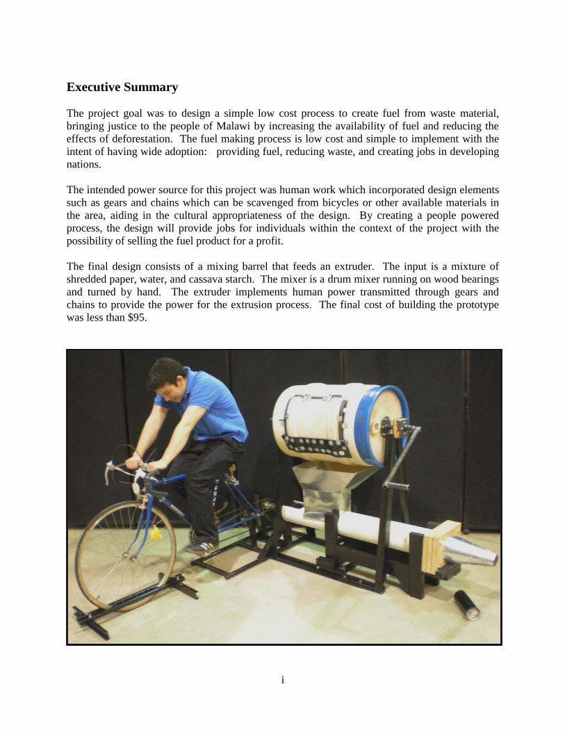
The final design consists of a mixing barrel that feeds an extruder. The input is a mixture of
shredded paper, water, and cassava starch. The mixer is a drum mixer running on wood bearings
and turned by hand. The extruder implements human power transmitted through gears and
chains to provide the power for the extrusion process. The final cost of building the prototype
was less than $95.

ii
Table of Contents
1 Introduction ............................................................................................................................... 1
1.1 Team Description ............................................................................................................... 1
1.2 Problem Statement .............................................................................................................. 2
2 Design Considerations ................................................................................................................ 3
2.1 Project Objectives ............................................................................................................... 3
2.1.1 Purpose of Design ....................................................................................................... 3
2.1.2 Cost ............................................................................................................................ 3
2.1.3 Reliability ................................................................................................................... 3
2.1.4 Scope .......................................................................................................................... 3
2.2 Design Norms ..................................................................................................................... 4
2.2.1 Stewardship ................................................................................................................ 4
2.2.2 Transparency ............................................................................................................... 4
2.2.3 Justice......................................................................................................................... 4
2.2.4 Cultural Appropriateness .............................................................................................. 4
3 Mechanism Design ..................................................................................................................... 5
3.1 Extruder Design .................................................................................................................. 5
3.1.1 Auger ......................................................................................................................... 5
3.1.2 Extruder Body ............................................................................................................. 6
3.1.3 Cone ........................................................................................................................... 7
3.2 Transmission Design ........................................................................................................... 9
3.2.1 Power Source .............................................................................................................. 9
3.2.2 Bicycle and Transmission Support Frame ...................................................................... 9
3.2.3 Transmission Bearings ............................................................................................... 10
3.3 Mixer Design .................................................................................................................... 10
3.3.1 Mixer Frame ............................................................................................................. 10
3.3.2 Mixer Bearings .......................................................................................................... 11
3.3.3 Barrel and Door ......................................................................................................... 11
3.4 Safety Considerations ........................................................................................................ 13
4 Testing and Briquette Production .............................................................................................. 14
4.1 Final Product .................................................................................................................... 14
4.1.1 Product Properties ..................................................................................................... 14
4.1.2 Production Tests ........................................................................................................ 15
4.1.3 Burning Tests ............................................................................................................ 15
4.2 Trouble Shooting .............................................................................................................. 16
4.2.1 Extruder Placement.................................................................................................... 16
5 Project Organization ................................................................................................................. 17
5.1 Schedule .......................................................................................................................... 17
5.1.1 List of Key Milestones ............................................................................................... 17
5.2 Re-Fueled Member Contributions ...................................................................................... 17
6 Budget ..................................................................................................................................... 18
6.1 Senior Design Budget ....................................................................................................... 18
6.2 Malawian Design Budget .................................................................................................. 19
7 Conclusion .............................................................................................................................. 20
7.1 Lessons Learned ............................................................................................................... 20

iii
7.2 The Future of Re-Fueled ................................................................................................... 20
7.2.1 The Project................................................................................................................ 20
7.2.2 The Team .................................................................................................................. 20
8 Acknowledgements .................................................................................................................. 21
8.1 Contact in Malawi ............................................................................................................. 21
8.2 Faculty Advisor ................................................................................................................ 21
8.3 Industrial Consultant ......................................................................................................... 21
8.4 Shop Aid .......................................................................................................................... 21
8.5 Administrations ................................................................................................................ 21
Table of Figures
Figure 1.1: Team Re-Fueled .......................................................................................................... 1 Figure 3.1: Final Mechanism Prototype......................................................................................... 5 Figure 3.2: Farm Auger for Extruder ............................................................................................. 6 Figure 3.3: Extruder Shown in Extruder Body .............................................................................. 7
Figure 3.4: Cone and Flange Assembly ......................................................................................... 8 Figure 3.5: Compression Cone Attached with Wooden Flange .................................................... 8 Figure 3.6: Diagram of Interior Wooden Flange Layer ................................................................. 9
Figure 3.7: Mixer Frame .............................................................................................................. 10 Figure 3.8: Parts of the Wood Bearings ....................................................................................... 11
Figure 3.9: Shaft Connection within the Mixer ........................................................................... 11 Figure 3.10: Plates Connecting the Shaft to the HDPE Barrel .................................................... 12 Figure 3.11: Mixer Door .............................................................................................................. 12
Figure 4.1: Final Briquettes ......................................................................................................... 14
Figure 4.2: Burning Briquette ...................................................................................................... 15
Table of Tables
Table 6.1: Preliminary Senior Design Budget ............................................................................. 18

1
1 Introduction
The country of Malawi is among the top 10 poorest countries in the world. Numerous
organizations invest time and effort into aiding the people of Malawi—meeting their basic needs
such as water, food, shelter, healthcare, and many other essentials. Despite these efforts, the
country of Malawi is still in great need. Currently, deforestation is an increasing problem in
rural areas of Malawi, as the demand for charcoal fuel requires more resources than are
available. This is a very unsustainable, temporary, and environmentally damaging solution.
As a team of aspiring Christian engineers, Re-Fueled (one of fifteen Senior Design groups) has
taken on this design project based on a desire for addressing environmental problems and using
gifts and talents to aid the developing world. In working with Larry McAuley, a Malawi based
member of Christian Reformed World Relief Committee, the team gained a more culturally
specific understanding of Malawi. The need for inexpensive fuel in Malawi requires a solution
which Re-Fueled has defined. On completion of the design project, the plan was sent to Larry as
a proposal in hopes of being adopted by CRWRC in Malawi.
1.1 Team Description
Re-Fueled is composed of three senior Calvin College engineering students in the mechanical
concentration: Jeff De Jong, Bethany Kortman, and Jeena Velzen.
Figure 1.1: Team Re-Fueled (Left-to-Right: Bethany Kortman, Jeff De Jong, Jeena Velzen)
Jeff De Jong grew up in Glendale, California where he has worked as a swim coach at the local
country club. Jeff obtained a degree in both engineering and business information systems. He
enjoys working on his computer as well as riding and repairing his two motorcycles. After
graduation, Jeff intends to return to California to pursue a career in automotive engineering.
Bethany Kortman was raised in Grandville, Michigan where she attended Calvin Christian High
School. She has received an international designation to her degree for her participation in an

2
internship for Solvay Pharmaceuticals in Weesp, Netherlands and an interim abroad. Bethany
plays lacrosse and enjoys cycling. She also enjoys outdoor recreation including hiking,
climbing, and camping. After graduation, Bethany hopes to work abroad for a few years and
then settle down at an architecture and engineering firm in the West Michigan area.
Jeena Velzen was raised in Jenison, Michigan and worked for Gentex Corporation, participated
as a leader for a Wilderness Orientation Trip, and was a resident assistant for the Entrada
Scholar’s Program at Calvin College. Jeena is a member of the Calvin Swim and Dive Team as
a 1 and 3 meter springboard Nationals diver. After graduation, Jeena hopes to pursue further
education and work internationally.
1.2 Problem Statement
Living requires fuel. Even in the most rustic and primitive areas of the world, fire is required to
cook food and to provide heat. In many developing countries where electricity is not widely
available and fossil fuels are too expensive, wood is the primary source of fuel. Malawi is a
country of particular interest which has been ravaged by its people, stripping its landscape of
forests to produce charcoal.
Malawi is a country the size of Pennsylvania in southeastern Africa, with a population slightly
larger—nearly 14 million. A large majority, roughly 85%, of Malawians are poor subsistence
farmers living in rural Malawi1. A very shocking comparison shows the per capita GDP of
Malawi is $800 compared to Pennsylvania’s of greater than $40,000. Malawi is currently
experiencing massive deforestation to provide fuel for its people. Because of this, homemade
charcoal from trees is illegal; however, deforestation continues. These circumstances present a
need for an inexpensive fuel source which does not encourage the environmentally damaging
process of providing fuel which is currently destroying the Malawian landscape.
Re-Fueled designed a process and mechanism which can provide an affordable fuel made from
materials which would otherwise be wasted. Keeping the Malawian people in mind as the end
users, the design is bound by considerations for the culture and circumstances surrounding
Malawi.
With a heat content of approximately 8,000 BTU/lb compared to charcoal’s 9,000 BTU/lb, paper
is an excellent substitute which can be readily found in the streets of Malawian cities.2 Re-
Fueled designed this mechanism to provide an adequate substitution for charcoal production
while also aiding in cleaning the city streets in Malawi.
1 CIA World Factbook (www.cia.gov)
2 Robert L. Brauer, Safety and Health for Engineers

3
2 Design Considerations
When confronting a stated problem, proposed designs must be fashioned from objectives which
are intrinsic to the problem statement. In addition, these designs are defined by norms which are
specific to the designer. The following sections will layout the multiple objectives of this design
project.
2.1 Project Objectives
2.1.1 Purpose of Design
Re-Fueled’s design serves the purpose of using scrap materials found locally to complete
the task of creating fuel from waste paper. The design purpose is specific to the end user
and works to meet culturally specific needs.
2.1.2 Cost
Minimal cost was a primary objective in the design of a functional mechanism for
producing fuel from waste in a developing country. The Senior Design budget was $300
per project; however, the Malawian salary is an average of $160 per year. To meet the
budget restrictions of the Malawians, Re-Fueled gathered scrap materials from bikes and
farm equipment for the construction of the mechanism. Using parts that can be found for
low or no cost in Malawi made the design an appropriate replacement for charcoal
production in developing countries.
2.1.3 Reliability
Reliability is an important aim because of the cultural differences between Malawi and
the United States. A “fix it” mentality cannot be assumed for the individuals who will be
the end users of the mechanism. Over time, if the mechanism breaks, the design must be
simple enough so a large range of people could repair it. The design of this mechanism
will focus on being very simple to understand, but also to be able to withstand frequent
use without breaking down or needing repair. Although the simplicity of design aims to
enable operators to repair the machine, reliability is of primary importance.
2.1.4 Scope
The scope of this design project is a very important intent which must be defined.
Although there are many possibilities for the production capacity of this design, the scope
must be limited to fuel a small community. The finished project could prove to be viable
for a small business, but the intent of the design is to produce enough useable fuel in one
operating period for a week’s worth of fuel for a single family.

4
2.2 Design Norms
In addition to typical project objectives, there are a number of design norms which tie into the
ethical, and more specifically Christian, perspective for the design of this project. Christian
engineers are called by God to adhere to higher standards, which they incorporate, by their faith,
into their design.
2.2.1 Stewardship
The team name, Re-Fueled, is derived from the team’s desire to design a solution from
readily available materials that would otherwise be wasted. The current problems of
deforestation3 within Malawi can be offset by this design which converts waste—using a
machine made of re-used components—to useable fuel. Reusing components and
reducing the damage caused by unsustainable deforesting are all aspects of being
Christian stewards of God’s creation and being responsible caretakers of the earth and its
resources.
2.2.2 Transparency
Transparency becomes an important concept of design for Re-Fueled when considering
the end user of the device and the product. For the fuel-briquette making device to be a
useful resource for the people of Malawi, its intent and purpose must be transparent. Re-
Fueled accomplished this by designing and building with commonly used materials that
have obvious purposes.
2.2.3 Justice
There are many inequities within societies; this design seeks to bring justice to areas like
Malawi where individuals and families struggle to afford fuel to cook food and heat
homes. Everyone should have the right to earn a living. By aiming to supply jobs and
provide safe inexpensive fuel, this design will work toward justice on the very basic level
of fulfilling some needs for God’s people.
2.2.4 Cultural Appropriateness
The design for this project must agree with the culture and environment of Malawi.
Considering materials that can be easily acquired for a low cost in the area will aid in
achieving this goal. Also, for the device to be accepted and easily adopted, the machine
must be very simple to assemble, use, and repair. By keeping the use of materials limited
to locally available scrap and making the device simple, this project will make cultural
appropriateness a priority. Larry McAuley will act as a liaison, communicating the needs
and concerns of the theoretical Malawian end users, to help the team be as immersed as
possible in the Malawian culture.
3 CIA World Factbook (www.cia.gov)
5
3 Mechanism Design
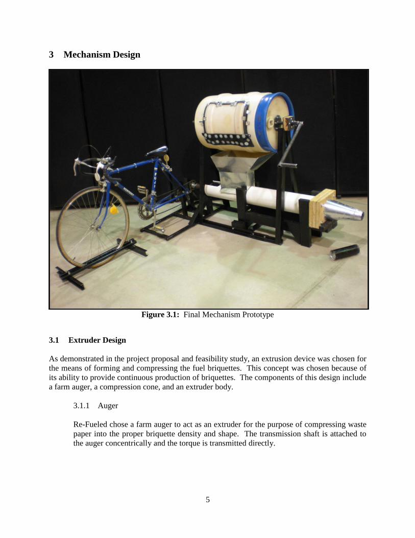
Figure 3.1: Final Mechanism Prototype
3.1 Extruder Design
As demonstrated in the project proposal and feasibility study, an extrusion device was chosen for
the means of forming and compressing the fuel briquettes. This concept was chosen because of
its ability to provide continuous production of briquettes. The components of this design include
a farm auger, a compression cone, and an extruder body.
3.1.1 Auger
Re-Fueled chose a farm auger to act as an extruder for the purpose of compressing waste
paper into the proper briquette density and shape. The transmission shaft is attached to
the auger concentrically and the torque is transmitted directly.

6
Figure 3.2: Farm Auger for Extruder
The auger, shown in Figure 3.2, was obtained from a farm equipment scrap yard in
Wayland, MI and is approximately 5 ft in length with a diameter of 5.5 in. The diameter
of the auger’s inner shaft was 1 in, and the pitch is about 0.18 threads per inch. This farm
auger was probably used as part of a combine to transfer material from one place to
another with a packing density of about 70%. This was not ideal for our extruder as its
purpose is to move material—not compress it—as it has a constant pitch; but it was the
most available option. Ideally a compression auger that had a decreasing pitch would
produce more compression. To make up for this deficiency the tip of the auger was cut
down so that it fit further into the compression cone.
3.1.2 Extruder Body
To house the extrusion mechanism, a 6 in. schedule 40 PVC pipe was acquired. The
purpose of the extruder body was to provide a close fitting frame for the auger to push the
material through. An oval-shaped hole was cut in the top of the extruder body so the
materials could be easily dropped in while the extruder is in motion (Figure 3.3).

7
Figure 3.3: Extruder Shown in Extruder Body
The extruder is cantilevered inside of the extruder body and the extruder body is
supported with a simple wooden frame. The frame arrests the extruder body by the cone
to keep the thrust forces from pushing the extruder body off of the frame. Without this
frame and the stop by the cone of the body the extruder body would be pushed forward
off of the auger.
3.1.3 Cone
To achieve the desired briquette compression and shape, a compression cone was
designed to fit on the end of the extruder body. As the extruder pushes the material
through the cone, it is compressed by a 5:1 compression ratio, meaning the volume of the
input material is decreased by 5 times. The material leaving the cone is cylindrical in
shape with a diameter of 3 inches. The cylindrical product is then cut into sections with 1
inch thicknesses and the pieces are dried as individual briquettes. The cone was created
from sheet metal and attached to the extruder body with a wooden flange and is shown in
Figure 3.4 and Figure 3.5. The wooden flange has an groove cut in the interior layer as
shown in Figure 3.6, which fits a ring of PVC which is glued to the outside of the
extruder body.

8
Figure 3.4: Cone and Flange Assembly
Figure 3.5: Compression Cone Attached with Wooden Flange
Extruder Body Sheet Metal Cone Flange
Front Wood Flange
Sheet Metal Cone
PVC Ring
(fixed)
Connecting Bolts
Back Wood Flange
3” 6.625”

9
Figure 3.6: Diagram of Interior Wooden Flange Layer
3.2 Transmission Design
To run the mechanism and produce fuel briquettes, Re-Fueled designed a transmission setup that
incorporates bike power, spare bike parts, and metal scraps. All of the aspects of the
transmission design work together to make the component fit into Re-Fueled’s goals of
stewardship and cultural appropriateness.
3.2.1 Power Source
Cultural appropriateness is an important design norm for this project and it was
considered in every facet of the design. Reliable electricity is rare in many developing
countries, including Malawi. Daily activity is often governed by the occurrence of
rolling blackouts and many rural areas are not equipped with electricity at all. This fact
inspired Re-Fueled to make the fuel-producing device completely human powered.
Because cycling is a common form of transportation world-wide, bicycle power was
chosen for the power source. The goal of the transmission design was to provide a
method to power the device without altering the operator’s bicycle so that any person can
ride their bike up to the device, attach it easily, produce their necessary fuel supply, and
ride away. Through careful planning, these goals were met by means of a bicycle and
transmission support frame.
3.2.2 Bicycle and Transmission Support Frame
To support the bicycle and transmission system, a frame was built with scrap steel. The
frame was designed around the concept that the actual bicycle would not be permanently
modified for fuel production use. To accomplish this goal, issues with clearance and
proper support were addressed through the use of CAD planning and finite element
analysis, samples of which are shown in the Appendix.
10
3.2.3 Transmission Bearings
Despite Re-Fueled’s efforts to design completely with used and locally available
materials, one exception had to be made. The movement and compression of the material
down the auger and through the cone creates a significant thrust force in addition to the
force supporting the auger. With the extruder body properly anchored the auger
experiences the full brunt of this thrust force and this force must be removed before
entering the transmission. A taper bearing with a inner diameter of 0.75 in and outer
diameter of 2.5 in was used to handle the thrust and the load. This bearing was mounted
in a bearing pocket to provide support for the raceway. This bearing pocket was then
attached to the transmission support frame. The thrust is transmitted from the auger to
the taper bearing using a thrust washer; this removes the thrust force from the shaft
allowing for the proper and consistent operation of the transmission. The bearing was
provided by the Calvin College Metal Shop. All other bearings used in the design can be
found on your typical bicycle and were adapted to fit into our design.
3.3 Mixer Design
3.3.1 Mixer Frame
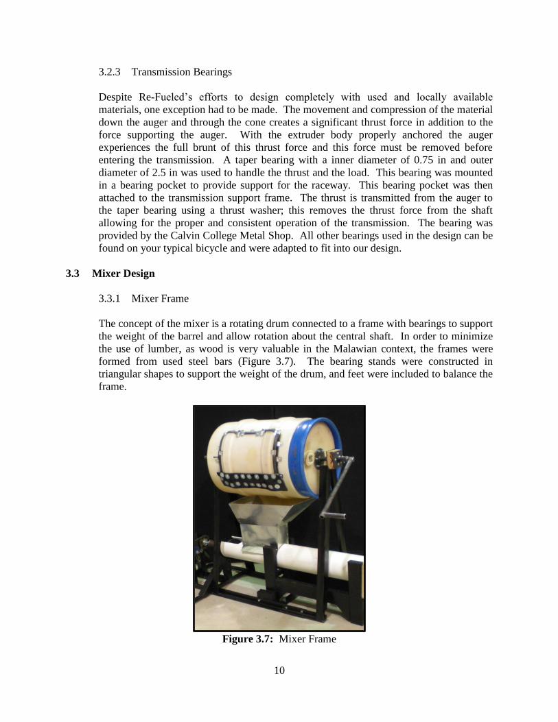
The concept of the mixer is a rotating drum connected to a frame with bearings to support
the weight of the barrel and allow rotation about the central shaft. In order to minimize
the use of lumber, as wood is very valuable in the Malawian context, the frames were
formed from used steel bars (Figure 3.7). The bearing stands were constructed in
triangular shapes to support the weight of the drum, and feet were included to balance the
frame.
Figure 3.7: Mixer Frame

11
3.3.2 Mixer Bearings
The mixer needed to rotate through bearings which were mounted on the mixer frame.
Steel bearings were excluded because they are not easily accessible parts, and the goal
was to be culturally appropriate with the use of materials and their functions. A wood
bearing was selected as it can be constructed from scrap wood and will provide adequate
rotational capabilities with lubrication and a brass lining. Figure 3.8 shows the parts of
the wood bearing.
Figure 3.8: Parts of the Wood Bearings
3.3.3 Barrel and Door
The barrel that was used for the mixer was a 30 gallon, high density polyethylene
(HDPE) drum which was donated to the project. The barrel sits horizontally and rotates
with a shaft that was fixed through the center. The shaft was cut in two and connected in
the center of the barrel with a sleeve and bolts as shown in Figure 3.9.
Figure 3.9: Shaft Connection within the Mixer

12
To avoid tear-out of the plastic barrel, the shaft was fixed to the barrel by welding outside
plates to the shaft and bolting through the plastic to an interior plate on each side of the
barrel, shown in Figure 3.10.
Figure 3.10: Plates Connecting the Shaft to the HDPE Barrel
As material must be input and output from the barrel into the extruder hopper, an opening
needed to be created in the barrel. A door was cut from the barrel to be attached with
piano hinge and closed with latches. As the door is the exact size of the opening, a lining
needed to be created to provide a proper seal in order to avoid leaking. Bicycle tire
rubber was used line the door and the opening. Glue could not be acquired easily which
could act as an adhesive for rubber to HDPE, so small metal bands were bolted through
the plastic to hold the rubber to the plastic. The door needed to be overlapped a
significant amount to seal on the latch side, so scrap rubber was used to close the gap
over the hinged portion of the door as shown in Figure 3.11.
Figure 3.11: Mixer Door

13
3.4 Safety Considerations
Because this device will be in close proximity to its operators and their homes, safety
considerations influenced the design and construction process.
Extruder
o Effort made to limit access to moving parts and pinch points
No access to auger because of mixer placement
o Reinforcements were made to keep parts from coming loose (busting)
o Operates in only one direction
Transmission
o Operates at slow speed to minimize possibility for injury
o Design allows for gear changing
o Guard necessary to prevent injury due to moving parts
Bike Frame
o Supports keep bike from tipping
o Variable height for different bike sizes
Mixer
o Door latched securely
o Barrel mixer operates at slow speeds
o Mixer frame designed to not interfere with operator
o Frame ergonomically friendly height
o Mixer placed directly over extruder to limit transportation of in-process
material
Potential Hazards
o Sharp edges on sheet metal
o Rotating parts create pinching hazard
o Material output at a low height
o Little control over purity of material input

14
4 Testing and Briquette Production
4.1 Final Product
Figure 4.1: Final Briquettes
4.1.1 Product Properties
The final briquettes produced by Re-Fueled’s device are approximately 1 inch thick and
cylindrical in shape with a 3 inch outer diameter. According to New Dawn Engineering’s
tests on similar briquettes, paper briquettes should have an average density of
approximately 0.2 g/cc or 0.007 lb/in3.4 Using information about the heat content of
paper, the briquette dimensions, and average density, the briquettes should have an
estimated heat content of approximately 360 BTUs each. To give an example of what
this means, 1 paper briquette could raise the temperature of 2 quarts of water by 72 °F.
These properties are theoretical based upon design specifications and research and
therefore do not include the heat losses due to actual burning conditions and inconsistent
materials. In order to determine Re-Fueled’s actual briquette properties, production tests
were completed.
4 New Dawn Engineering (www.newdawnengineering.com)

15
4.1.2 Production Tests
Throughout the design and construction of the device, many production tests were
completed. The first test was done to determine the appropriate proportions of water,
starch, and paper for optimum briquette formation. This test was done before the
construction of the machine and was based on the preliminary design specifications.
After construction, many composition tests were completed to determine the optimal
ratios. This was necessary because the effects of the composition on the briquette
production were much greater than first anticipated. Cassava starch, the binding agent in
Re-Fueled’s briquettes, must be added in order for the process to produce briquettes
consistent in shape and composition; however, adding too much starch created too much
friction inside the extruding mechanism and the extruder body clogged. Many tests were
necessary before an acceptable composition was determined.
After the construction of the device and briquette compositions tests were completed,
briquette production began. A large quantity of briquettes was necessary in order to
determine the running consistency of the device, and the average density of the final
product. The briquettes were extruded and placed in a toaster oven for quick drying. The
briquettes were then measured and weighed to determine average density which was
determined to be approximately 0.008 lb/in3 which is very consistent with the value of
0.007 lb/in3 found during research, mentioned above.
4.1.3 Burning Tests
Figure 4.2: Burning Briquette
After a number of consistent briquettes were produced, it was possible to do briquette
burning tests. During these tests, briquettes were burned individually and observed for
total burning time and completeness of burn. During these tests it was determined that
one briquette burns for an average of 15 to 20 minutes, during which the entire briquette
is consumed with only a small amount of ash remaining.

16
4.2 Trouble Shooting
As Re-Fueled completed briquette production and burning tests, problems were encountered and
handled through troubleshooting. This allowed the team to quickly get passed problems and
move on to the next step.
4.2.1 Extruder Placement
One problem encountered by Re-Fueled during the testing process was the sensitivity of
the extruder placement inside the extruder body. It was noticed that because the extruder
did not enter the compression cone on the end of the extruder body, often the material
would jam at the entrance to the cone instead of throughout the length of the cone.
Fixing this problem required the auger extruder to be tapered at the compression cone
end. Doing this would allow the auger to protrude into the compression cone and force
the compressed material out the opening. This was done by using a plasma cutter to
make the auger diameter smaller at the compression end. This troubleshooting solution
had the desired effect and the material was able to pass through the compression cone
completely.

17
5 Project Organization
5.1 Schedule
5.1.1 List of Key Milestones
The following is a list of significant project milestones that have been achieved in the
final design and implementation process. Milestones are marked by their completion
time.
February 13 Preliminary Composition Tests
February 21 Materials & Parts Acquisition
March 2 Cone Construction & Attachment
March 13 Extruder Construction
March 20 Bike Stand Construction
April 10 Transmission Frame Construction
April 17 CEAC Project Review
April 24 Transmission Construction
May 1 Mixer Construction
May 3 Batch Testing
May 4 Final Assembly
May 5 Burn Tests
May 9 Senior Design Banquet
5.2 Re-Fueled Member Contributions
The team worked for nearly three months in the planning and feasibility testing stages of the
project. Four months were available for construction and redesigning. Throughout this time, the
team separated work to be able to work more efficiently. The work was split three ways in order
to delegate tasks to fit each members skills and interests.
Jeff DeJong was a key worker on the construction of the extruder and transmission. Jeff crafted
the cone and wooden flanges as well as machining various pipes and shafts to connect the auger
shaft to the sprocket bearing.
Bethany Kortman focused much of her effort on stress analysis, design, and construction of the
bicycle frame, as well as the extruder frame. As a cyclist in her spare time, she used her
experience with bicycle repair to aid in transmission design and construction. Beth worked on
briquette testing, worked with Jeena on the hopper design and construction and wrote a
significant part of the final report.
Jeena Velzen: designed and constructed the mixing component and support frames. She also
constructed the hopper that joins the mixer with the extruder. Jeena worked with Beth in testing
the fuel as well as writing the final report.

18
6 Budget
Since the context for this project is assembly and implementation in a developing nation, there
are two different budgets to take into consideration. The first is the budget for the prototype
determined by the Senior Design class. This includes expenses for feasibility testing, materials,
research, tools, etc. The Senior Design budget is defined to be an average of $300 per project.
The second budget to consider is the budget for implementation in Malawi. This budget must
cover all start up costs involved with the machine and process including construction materials,
tools, and labor. The budget for implementation in Malawi is based on the average salary of
about $160 per year as expressed by Larry McAuley, while keeping in mind the aid provided by
relief missions like CRWRC.
6.1 Senior Design Budget
The Senior Design budget was analyzed based on the project expenses throughout the year,
including building and production materials. The project budget was kept low because of the
donations and the use of scrap materials (Table 6.1).
Table 6.1: Final Senior Design Budget
Part Cost Qty Where Acquired
Bicycle Sprocket $0.00 1 Donated
Bicycle Chains $0.00 2 Donated
Bicycle Tubes $0.00 2 Donated
Auger $15.00 1 Stamm Equipment Co.
Sheet Metal $0.00 Donated
All Steel $0.00 Donated
All Fasteners $0.00 Donated
HDPE Barrel $0.00 1 Donated
Thrust Bearing $0.00 1 Donated
PVC Pipe (schedule 40) $50.00 10 ft Vander Lind and Sons
Cassava/Tapioca Starch $21.28 1 lb Barry Farms
Latches $0.00 2 Donated
Piano Hinge $0.00 1 Donated
Lumber (2x4 studs) $3.00 2 Lowe's
Contact Cement $4.74 1 Lowe's
Total $94.02
The preliminary total of $225 as determined during the project proposal and feasibility study
stage of the process was a very conservative estimate that Re-Fueled was able to beat
tremendously.

19
6.2 Malawian Design Budget
In order for the design to be culturally appropriate, it is immensely important consider the final
product costs in the context of Malawi. Through communication with Larry McAuley from
CRWRC, the team was able to determine availability of the necessary parts and an effort was
made to make sure that the design consisted of easily available materials. The exact budget is
difficult to determine because the cost of all materials cannot be identified completely.
However, since the testing and designing processes were completed in the U.S. under the Senior
Design Budget, only the final design materials need to be considered in the Malawian Budget.
Because of the lack of cost data for materials in Malawi, the total project cost in the US budget is
still low enough to be a reasonable cost in Malawi. There is also the possibility of finding the
materials for no cost in trash piles and through donations from local aid sources, emphasizing the
goals of stewardship and caring.

20
7 Conclusion
7.1 Lessons Learned
As Senior Design is intended as an educational process for engineers, the lessons learned from
that process were very valuable. Due to the nature of Re-Fueled’s project, incorporating
recycled materials for the prototype construction, iterative design was necessary as well as
flexibility and robustness of design. Many changes needed to be made in order to use parts that
became available. The design was greatly affected by the need presented by the problem
statement. Keeping the end user in mind for the entire process was very important to best
provide a suitable product.
The implementation and actual construction of the design presented a number of challenges
which taught the team numerous lessons. Delegating work is very important when working in a
team. The “divide and conquer” method of work greatly improves efficiency and allows team
members to use their strengths to the best of their ability. The team also learned that
construction can take a significant amount of time. Manufacturing appropriate tolerances is very
important in a design and when that is not done well the first time, further re-work and re-
machining takes even more time than planned. In scheduling a design and implementation
process, time should be taken into account for mistakes, testing, and re-design.
Among the many lessons learned, the one that will continue to follow the team members from
this project is the satisfaction that comes from using engineering for a higher purpose. The roots
of the project came from a desire for incorporating stewardship and justice into engineering. By
constructing a machine from waste materials to provide for a group of people in need, the
Kingdom is brought to earth and there is more Shalom in the world. The desire to work for God
and for the needs of His people will remain in the hearts of the Re-Fueled members as they
continue in their careers.
7.2 The Future of Re-Fueled
7.2.1 The Project
The design has been left in the hands of Larry McAuley for implementation in Malawi.
Re-Fueled hopes their method of briquette production will become a staple in the villages
of developing world countries. The work Re-Fueled has done will be published for
public use on the Senior Design website.
7.2.2 The Team
The team will graduate in May 2009 and move on to the next steps of their lives.
Bethany and Jeena will continue to work in the West Michigan area for Gentex
Corporation in engineering. Jeff will be pursuing work in the automotive industry while
also using his IT knowledge in the Chicago area. The team members will continue to
follow their passions for helping others throughout their engineering careers.

21
8 Acknowledgements
8.1 Contact in Malawi
The design for a fuel briquette making device aimed at developing countries would not fulfill the
goal to be culturally appropriate without the help of Larry McAuley in Malawi. As a member of
CRWRC in Malawi, Larry works side by side with the people this design is aimed to help. His
insights into the culture and needs of the people made him an extremely valuable contact for the
team. Re-Fueled hopes to continue contact with Larry as the design is proposed for
implementation in Malawi.
8.2 Faculty Advisor
Professor Aubrey Sykes was the faculty advisor for Re-Fueled and provided valuable insights
into the process of implementing a design from the concept to the final produced mechanism.
Professor Sykes helped to keep the team in line and on track. His guidance was very important
for the development of the project.
8.3 Industrial Consultant
Each design team is assigned a consultant with professional experience to mentor them in their
journey from project feasibility through design implementation. Re-Fueled’s industrial
consultant was Dr. David Dornbos. His work with energy efficiency and recycling at Steelcase
has made him a very knowledgeable resource for Re-Fueled throughout the year.
8.4 Shop Aid
Throughout the design and construction of this project, Phil Jasperse has leant his knowledge
about materials, machining processes, and design capability. Phil has aided the team through the
metal shop class he offers where Re-Fueled learned the skills of milling, lathing, welding, and
many others. Many thanks are due to Phil for his help throughout the year.
8.5 Administrations
There are a few staff members in administrations that should be recognized for their significant
work in aiding the engineers throughout the Senior Design year. Michelle Krul, the Engineering
Department Administrative Assistant, helped in notifying the teams of deadlines as well as
helping with the team booklets and posters. Bob DeKraker, the Engineering Lab Manager,
helped provide the teams with orders of materials and electronic necessities. Both were patient
and kind in the process, and the teams are very grateful.